medium voltage high-power converter topology for … 1487 medium voltage high-power converter...
TRANSCRIPT

Page 1487
Medium Voltage High-Power Converter Topology for 10MW Wind
Generation with the Large Permanent Magnet Wind Generator
Systems
B. Sri Nandini
M.Tech (Power Systems)
KSRM College of Engineering, Kurnool.
Mr. Bhaskar Reddy
Associate Professor
KSRM College of Engineering, Kurnool.
ABSTRACT
This paper proposes a modular, medium voltage, high-
power converter topology for the large permanent
magnet wind generator system, eliminating the grid-
side step-up transformer, which is desirable for both
onshore and offshore wind turbines. The power
conversion systems for large wind turbines are facing a
great challenge as today’s wind turbine power outputs
approach 5 MW and above. The conventional low
voltage power conversion system will suffer from a
high transmission current, which significantly
increases losses and cost of the cables as well as
voltage drop. The converter modules are cascaded to
achieve medium voltage output. Each converter
module is fed by a pair of generator coils with 90
phase shift to get the stable dc-link power. At the grid-
side, H-bridge inverters are connected in series to
generate multilevel medium voltage output and the
voltage- oriented vector control scheme is adopted to
regulate the converter active and reactive power
transferred to the grid. The power factor correcn (PFC)
circuit enables the generator to achieve unity power
factor operation and the generator armature inductance
is used as ac-side PFC boost inductance. Simulation
results with a 2-MW wind turbine system and
experimental results with a down-scaled 3-kW system
validate the proposed topology and control methods.
The proposed system can successfully deliver power
from the wind generator to the grid.
INTRODUCTION
Today, the most popular large variable-speed wind
turbines are rated around 1.5–3 MW. Nevertheless, 7-
MW wind turbines have recently appeared and even
larger wind turbines, e.g., 10MW, are under
development in order to reduce the unit cost of wind
power generation [1], [2]. Wind turbines equipped
with direct-drive permanent magnet generators
(PMGs) and full power converters are generally
favored due to simplified drive train structure and thus
higher reliability, especially for offshore applications,
compared with the doubly fed induction generator-
based system. Most of the present wind generator and
power converter systems are based on the 690Vand
two-level voltage–source or current–source converters
are normally used [3], [4]. The continuous increase in
wind turbine power ratings will generate larger
current, e.g., from 1673 A for 2-MW system to 8810 A
for 10-MW system. Power converters are therefore
connected in parallel to handle the increasing current
[5], [6]. Meanwhile, large current transfer results in a
parallel connection of multiple power cables going
down through the tower and causes substantial losses (
), voltage drop, as well as high cost of cables,
switchgears, and terminal connections [7]. These
disadvantages can be offset by placing the step-up
transformer (e.g., 690 V/33 kV) into the nacelle.
However, the bulky and heavy transformer occupies
the limited space of the nacelle and increases the
mechanical stress of the tower. Therefore, a medium-
voltage power conversion system (e.g., 10 kV) would
be more desirable for large wind power conversion by
reducing the current level and associated cable cost
and losses, as well as improving the system power
density. The benefits of adopting medium-voltage
power conversion technology have been proved in
motor drive applications, where medium-voltage (3–33
kV) configuration is generally used when the system
power rating is higher than 1 MW [8]. Table I shows
the current rating of an exemplar 5- and 10-MW
systems with 690-V and 10-kV voltage level for
comparison. As seen, transferring from low voltage

Page 1488
(690 V) to medium voltage (10 kV) can significantly
reduce the current level. Further, considering the high
maintenance cost and fault-tolerant requirement
especially for offshore wind applications, a modular
converter and generator structure is even preferable.
Regarding medium-voltage multilevel converter
topologies for wind power applications, papers [9]–
[12] investigate the suitability of three-level neutral-
point-clamped converters. Although a higher voltage
rating and reduced output harmonics are achieved, the
ac-side voltage is limited to 4.0 kV if using 4.5-kV
integrated gate-commutated thyristors (IGCTs) [11].
The voltage rating may be further increased if using 6-
kV IGCT; however, the cost and availability becomes
a major concern. A five-level hybrid converter
topology with increasing number of devices is
presented in [13] to further increase the converter
voltage and power capability. However, the reliability
restricts its application. If one device fails, the whole
converter system operation may be interrupted. A
more applicable way to achieve 6- or 10-kV medium-
voltage power conversion is through the cascaded
modular converter structure [2], [8]. The voltage level
can be easily scaled up by cascading more converter
cells. Papers [14]–[18] have proposed various
converter topologies based on this concept. However,
the fundamental connections between these topologies
are not analyzed. The cascaded converter topology has
intrinsic fault-tolerant operation capability. If one cell
fails, it can be bypassed and the rest healthy cells can
keep operation [17]. One of the main disadvantages of
the cascaded
TABLE I
WIND TURBINE CURRENT RATING FOR
DIFFERENT VOLTAGE LEVELS
Converter topology is the large dc-link capacitor
required to filter the dc-link voltage ripple from the H-
bridge side in each cell [14], [19]. The dc-link
capacitor is unreliable and is not favored in wind
power applications where maintenance cost is very
high. There are no effective solutions to significantly
reduce the dc link capacitor. In motor drive
applications, diode rectifiers are normally used, which
cannot be actively controlled to compensate the ripple
power thus reducing the dc-link capacitor.
In this paper, a fundamental rule to construct
multilevel modular high power converters for large
wind turbine power conversion is proposed. Based on
this, three potential multilevel modular wind power
converter topologies have been derived using a
generalized approach for an exemplar 10-kV, 10-MW
wind turbine. A special focus has been given to the
topology comprising a 10-kV generator, a multilevel
modular converter, and a multi-winding grid-side
transformer. A solution to reduce the dc-link capacitor
is proposed by compensating the ripple power from the
three-phase grid-side inverter. A resonant controller is
presented to achieve this purpose. The current
harmonics induced in the inverter and transformer
secondary windings by the proposed control scheme
and their impact are also investigated analytically. The
converter topology and dc-link capacitor reduction
strategy has been simulated and validated with a 10-
kV, 10-MW wind power conversion system, where the
dc-link voltage ripple is effectively attenuated without
affecting the grid power quality.
10-kV, 10-MW WIND POWER
MODULARCONVERTER TOPOLOGIES
As mentioned, one of the most applicable and
economic way to achieve a 10-kV power conversion
system is through series connection of modular
converter cells. In particular, 3.3-Kv insulated-gate
bipolar transistor (IGBT) device is considered in this
application due to their better availability and lower
cost, compared with 4.5- and 6-kV devices. Fig. 1
shows a generalized phase leg of a cascaded modular
converter structure. The outputs of several converter
cells (ac/dc/ac) are connected in series to achieve high-
voltage output. With 3.3-kV IGBTs, 10-kV line
voltage output can be achieved with five stages, where
each module dc-link voltage is regulated at around
1800 V, thus 3.3-kV devices can be used. It should be
noted that the converter modules in Fig. 1 cannot be
directly connected in series at both ends without

Page 1489
isolation. A galvanic isolation is needed in each
converter module in order to cascade the outputs at
either end. There are three possible locations to place
the isolation, viz., at the generator side (I), in the dc
link (II), or at the grid side (III), as shown in Fig. 1.
The isolation can be achieved through either generator
isolated windings, high-frequency transformer in the
dc-link or multi-winding grid-side transformer. Based
on this,
Fig.1. Generalized cascaded multilevel converter
topology (one phase leg).
Fig.2. High-power, medium-voltage (10 kV) modular
wind converter with generator-side isolation (converter
type I).
three potential high-power, medium-voltage modular
wind converter topologies are given in Figs. 2–4,
respectively.
Fig. 2 shows a high-power, medium-voltage (10 kV)
wind converter topology (type I) by using the
generator-side isolation. The isolated coils in the
generator stator windings are connected out separately
to provide independent power sources for each
converter cell. The input power stage of each cell is a
three-phase active rectifier and the output stage is an
H-bridge inverter. The outputs of each H-bridge are
connected in series to achieve high voltage (e.g., 10
kV) at the grid side. This topology requires the
generator to provide multiple three-phase coils. The
direct-drive PMGs generally have many pole pairs,
where the corresponding three-phase coils of each pole
pair (or several pole pairs connected in series or in
parallel, depending on the required voltage rating) can
be connected out separately to meet this requirement.
Regarding the control, the input three-phase rectifier is
responsible for regulating the dc-link voltage of each
converter cell and the grid-side cascaded H-bridge
converter regulates the active power [e.g., for
maximum power point tracking (MPPT)] and reactive
power fed into the grid [14], [16]. With this topology,
the generator and converter are suggested to put on top
of the wind tower. A step-up transformer from 10 kV
to the voltage level
Fig.3. High-power, medium-voltage (10 kV) modular
wind converter with high frequency transformer
isolation (converter type II).

Page 1490
(e.g., 33 kV) of the collection point of the wind farm
may be required and can be placed at the bottom of the
tower. Alternatively, a transformer-less structure may
be enabled if the number of cascaded stages can be
increased to directly meet the collection point voltage.
It should be noted that the increased number of
generator terminal connections may add extra labor
and maintenance cost. A dedicated generator design
and wire connection arrangement may be required.
Fig. 3 shows a second wind converter topology (type
II) with a high-frequency transformer as the isolation,
which is inserted into the dc link together with a back-
to-back H-bridge converter. This high-frequency
isolation unit is also called dual active bridge (DAB)
converter, where the two H-bridge converters at both
sides of the high-frequency transformer operate at a
higher frequency (e.g., several kHz), thus the size and
weight of the transformer can be significantly reduced
compared with the line frequency (50 or 60 Hz)
transformer [20], [21].
The input and output stages of each converter cell are
H-bridge converters (with the DAB converter in
between). A standard three-phase 10-kV generator is
used and the H-bridge converters are cascaded at both
the generator side and grid side to achieve 10-kV
voltage capability thus regulating the generator and
grid power.
The turns ratio of the high-frequency isolation
transformer can be adjusted (1:1 or 1: n) to achieve the
desired voltage level. The power converter can be put
flexibly either on top of the tower or at the bottom
since 10-kV voltage is achieved at both ends of the
converter. The main concern with this topology is the
extra losses caused by the inserted DAB converter and
high-frequency transformer, which may be mitigated
by using advanced magnetic material, soft-switching
topologies and new wide-bandgap power devices, e.g.,
silicon-carbide (Sic) based device.
Fig.4. High-power, medium-voltage (10 kV) modular
wind converter with grid side transformer isolation
(converter type III): (a) generator and converter
structure and (b) wind turbine electrical configuration.

Page 1491
Fig. 4(a) shows another high-power, medium-voltage
wind converter topology (type III) with a grid-side
isolation transformer, which will be further
investigated in this paper. As can be seen, this
topology adopts a standard 10-kV wind generator and
a grid-side step-up transformer with multiple
secondary windings (1140 V/33 kV), which provides
isolation of each converter cell and also boosts the
converter voltage to the grid voltage of 33 kV. The
power converter and the transformer can be put at the
bottom of the tower as shown in Fig. 4(b), which
reduces the mechanical stress of the tower and saves
the space in the nacelle. The input stage of each
converter cell is an H-bridge rectifier which is then
connected in series to achieve 10-kV voltage capability
to control the generator. The output stage of each
converter cell is a three phase inverter and is connected
to the transformer secondary windings, responsible for
regulating the dc-link voltage. Similar to the previous
two topologies, this modular structure benefits from
fault-tolerant capability, when one cell fails, it can be
bypassed by a switch connected in parallel to the H-
bridge converter output and the remaining health cells
can still maintain operation subject to the reduce of
power output. In view of the successful applications of
the cascaded H-bridge converter in high power motor
drive area, this topology may become a strong
candidate for future large wind turbine power
conversion systems [22].
It should be noted that the low-frequency single-phase
fluctuating power at the input stage of each cell (H-
bridge) in Fig. 4(a) will cause dc-link voltage ripple,
which gets larger with lower generator stator
frequency and higher power level. For variable speed,
direct-drive PMGs, the stator frequency is generally
low (e.g., below 15 Hz). Therefore, large dc-link
capacitance is required to smooth out the voltage
ripple appeared on the dc link, which are bulky and
significantly increase the system cost as well as cause
reliability issues due to the lifetime of electrolytic
capacitors. This issue also happens to the other two
topologies in Figs. 2 and 3. In Section IV, a solution to
reduce the dc-link capacitance will be introduced in a
later session.
10-MW WIND TURBINE SPECIFICATIONS
AND CONVERTER
CONTROL STRATEGY
A. 10-MW Wind Turbine Specifications
A 10-kV, 10-MW wind turbine and its PMG
parameters are designed. The rated speed of the wind
turbine is 10 rpm at wind speed of 12 m/s [23]. The
PMG has 90 pole pairs, corresponding to 15-Hz stator
frequency at rated speed. Fig. 5 shows the captured
wind power variation with the generator speed. The
wind turbine control should aim to capture maximum
wind power by regulating the generator speed/power
following MPPT under normal conditions.
B. Generator and Cascaded H-Bridge Converter
Control Strategy
The wind generator (PMG) shown in Fig. 4(a) can be
modeled in a synchronous rotating ( , ) frame [3], [24].
With rotor flux oriented control, the PMG torque can
be controlled by the –axis current, while the -axis
current is controlled to maximize the generator
efficiency. In order to achieve MPPT, the generator
torque reference is set as the product of the optimal
coefficient and the square of generator speed [25]. The
standard phase shifted pulse width modulation (PWM)
is adopted to modulate the cascaded H-bridge
converters, thus generating the required voltage
according to the voltage reference.
C. Grid-Side Inverter Model and Control Strategy
At the grid side, the three-phase inverter in each
converter cell as shown in Fig. 4(a) is responsible for
regulating the converter cell dc-link voltage,
transferring the active power generated from wind
generator to the grid. Since the inverter current is
actively
Fig.5. Variation of captured wind power with
generator speed under different wind speeds.

Page 1492
controlled to be sinusoidal, the topology in Fig. 4(a)
does not Need multiple phase-shifted transformer
secondary windings (Zigzag winding) for harmonics
reduction as the case in motor drive applications with
diode rectifier, leading to a simplified transformer
design. The transformer leakage inductance can be
further used as the filter inductance. The model of the
grid-side three-phase inverter in each cell on frame is
given as follows [3], [14]:
Where Le and Re are the transformer leakage
inductance and resistance; ud, uq, id, iq are the
voltages and currents on the transformer secondary
side in the d, q frame, respectively; are the output
voltages of the three-phase inverter in the switching
average model; and ωe is the grid line frequency.
If the -axis of the rotating frame is aligned to the
transformer secondary voltage vector, then uq=0 and
ud=E where E is the amplitude of the transformer
secondary voltage. The converter active power P and
Q reactive power can be formulated by
(2)
As seen, the active and reactive power flowing into the
grid can be controlled by -axis and -axis currents
independently. The grid-side three-phase inverter
control diagram is shown in Fig. 6. The outer loop is
the dc-link voltage control loop which is kept to be
1800 V and inner loops are -axis and -axis current
control loops. The -axis current can be used to provide
reactive power to the grid when required subject to the
current capability of the converter.
CONVERTER DC-LINK VOLTAGE RIPPLE
REDUCTION
A. Resonant Controller Added in the Control Loop
One particular issue with the converter topology
shown in Fig. 4(a) is the large dc-link capacitor
required in each cell to smooth the single-phase
pulsating power from the H-bridge (generator) side,
which can be expressed as
Where and are the amplitudes of the
generator voltage (uo, u) and current (Io, U) seen at
each cell, respectively. Is the average power
flowing into the converter cell ωo is the generator
stator frequency and φ is the generator power factor
angle. As seen, the second term in (3) represents the
pulsating power with the frequency of 2ωo, which
causes dc-link voltage ripple. The amplitude of dc-link
voltage ripple V can be expressed as
(4)
Where C is the dc-link capacitor and Vdc is the dc-link
voltage. As seen, the dc-link voltage ripple becomes
larger with lower generator frequency and higher
power rating. To keep the dc-link voltage ripple within
V, the required dc-link capacitance C can be
calculated by
(5)
For a 10-MW wind power converter with 15 cells (5
stages), 1800-V dc-link voltage, and 15-Hz generator
stator frequency, the required capacitor in each cell
will be 44 mF in order to keep the voltage ripple to be
within 5% (90 V) at the rated operating point.

Page 1493
To achieve such large capacitance at this voltage level,
many electrolytic capacitors need to be connected in
both series and in parallel, which are not only
expensive and bulky, but also cause reliability issues
of the system, since the electrolytic capacitor has
almost the highest failure rates in a typical wind power
converter system [26]. For offshore applications, high
reliability is a key to reduce the maintenance cost.
Therefore, an effective method to reduce the required
dc-link capacitor is critical. Due to the use of
controlled three-phase inverter in each cell, the power
transferred to the transformer secondary winding can
be well adjusted to compensate the power ripple from
the H-bridge rectifier. If the power of the three-phase
inverter in (2) is regulated the same as the power from
the H-bridge rectifier as in (3) (including the pulsating
power), in theory, no dc-link capacitor is required to
handle the low-frequency (2ωo) power ripple.
By equating (2) with (3), the inverter -axis current
becomes (6) under vector control
(6)
Where id,U and iq,U are -axis and -axis currents
assuming that the three-phase inverter is connected to
phase U of the generator. As can be seen, the -axis
current has an ac component with the
Fig.6. Vector control diagram of the grid-side inverter
in each cell (The PI controller is replaced with a PIR
controller when the dc-link voltage ripple reduction
function is enabled.).
Frequency 2ωo of, which is different from the
conventional control where only dc component exists.
If the -axis current of the three-phase inverter can be
controlled the same as in (6), then there will be no dc-
link low frequency voltage ripple in steady state.
However, the conventional proportional–integral (PI)
controllers used in standard dc-link voltage and current
loops in Fig. 6 can only guarantee zero steady-state
error for dc component, not at twice of the generator
stator frequency (2ωo ). Therefore, a proportional–
integral–resonant (PIR) controller is introduced here to
replace the PI controller thus regulating the pulsating
power 2ωo at frequency. The resonant frequency of R-
controller is set at 2ωo. The transfer function of the
PIR controller is given as follows [27], [28]:
(7)
Where KP, Ki, and are the proportional, integral, and
resonant coefficients, respectively.
The selection of KP and Ki will follow the standard
current loop design process to achieve a desirable
control bandwidth. Based on the grid-side inverter
model in (1), the -axis current loop plant model can
therefore be expressed as
(8)
Where and are treated as cross-coupling
terms. If is chosen as and is chosen as
where is the designed current-loop
bandwidth, the closed-loop transfer function will
become
(9)

Page 1494
It can be seen that the closed-loop transfer function is a
first order system with a bandwidth of . The -axis
current-loop diagram is shown in Fig. 7.
The selection of Kr is to make sure that there is
sufficient gain at the resonant frequency to reduce the
low-frequency current ripple. In theory, since the
resonant controller has infinite gain at
Fig.7. Current-loop diagram with a PI controller
the resonant frequency, Kr can be any positive value
(e.g., Kr > 1). However, in digital implementation, due
to discretization effect, the gain at the resonant
frequency may be limited. Therefore, a larger Kr value
is preferred. It should also be noted that if the Kr value
is too large, the stability of the system may be affected
especially when the resonant frequency is close to the
current-loop cross-over frequency.
Fig. 8 shows the open-loop and closed-loop frequency
domain response of using PI and PIR controllers for
comparison. The current-loop bandwidth
therefore,
KP= 0.3, Ki = 3 the resonant frequency = 100Hz
and Kr=100.
As seen, the resonant (R) controller creates an infinite
gain at the resonant frequency (100 Hz). In the closed
loop, this converts to unity gain and zero phase delay
at the resonant frequency, which means the real current
can follow the reference accurately. Therefore, the
ripple power can be effectively compensated and the
dc-link voltage ripple is reduced. The design of the
PIR controller for the voltage loop can follow the same
process.
In addition, considering the accuracy of the generator
Frequency /speed measurement, it is desirable to have
a certain tolerance
when setting the resonant frequency. Therefore, a band
pass controller/filter can be used, instead of the pure
resonant controller. This will improve the robustness
of the controller especially when there is small error in
the frequency measurement. The band pass controller
will also avoid the stability issues caused by the
infinite gain of the resonant controller at the resonant
frequency. The transfer function of the band pass filter
is given as follows:
(10)
Where is ωo the center frequency of the band pass
filter and ωb is the bandwidth of the band pass filter.
The band pass filter has a high, but limited gain at the
resonant frequency ωo, which can be further tuned by
the resonant gain Kr.
Note that the resonant frequency varies with the
generator frequency/speed. Therefore, the generator
frequency information needs to be fed to the PIR
controller to set the resonant frequency.
It should also be noted that on using this dc-link
voltage ripple reduction scheme, the power transferred
to the transformer secondary winding in each cell will
contain a power ripple, instead of a constant power. As
a result, the three-phase inverter current (transformer
secondary-winding current) is not sinusoidal and
contains harmonics.
However, these current harmonics are canceled with
each other among the transformer secondary windings
and do not appear at the transformer primary-side/
grid-side (33 kV) and therefore would not affect the
grid power

Page 1495
Fig. 8. Current-loop frequency response with PI and
PIR controllers: (a) open loop frequency response and
(b) closed-loop frequency response.
Quality. Section IV-B will analyze the current
harmonics in both the transformer secondary and
primary windings.
B. Current Harmonics Analysis
In the following analysis, the generator phases are
denoted by A, U, V, W, and the transformer primary
phases are denoted by A, B, C and the transformer
secondary phases are denoted by a, b ,c , respectively,
as indicated in Fig. 4(a).
Connecting to the cells of generator phase U is given.
Similarly, the corresponding -axis current of the three-
phase inverters of the cells connected to generator
phases V and W can be derived as in (11) and (12) by
considering the phase shift of 120
To analyze the current harmonics in the three-phase
inverter, the , currents given in (6), (11), and (12) are
transformed back to , , coordinate by using inverse-
Park transformation. For the cells connecting to phase
U of the generator, the inverter phase a current
(transformer secondary current) can be expressed as
where ia,Ui represents the phase current of the inverter
and the suffix U denotes the inverter cell which is
connected to phase U of the generator. Suffix i denotes
the ith module of the module string.θ0, Ui is the phase
angle of the transformer secondary voltage ωe and is
the grid frequency. As seen from (13), the inverter
phase current (transformer secondary current) contains
not only the fundamental component with the grid
frequency of ωe , but also the frequency components
ωe + 2ωo of and ωe - 2ωo . These current harmonics
are due to the compensation of the power ripple from
the H-bridge side.
Similarly, the inverter phase current of the cells
connected to generator phases V and W can be
expressed as in (14) and (15), respectively,

Page 1496
Where θ0, θ0Wi are the voltage phase angles of the
transformer secondary windings of the cells connected
to the generator phases V, W, respectively. In the
converter and transformer configuration shown in Fig.
4(a), all the transformer secondary voltages have the
same phase angle with respect to the primary side
.Therefore,
If the inverter phase a currents of the cells connected
to generator phases U, V, W, as shown in (13)–(15),
are added together, the total phase current becomes
As seen, the harmonic currents with the frequency of
ωe + 2ωo and ωe - 2ωo in each cell are canceled
among the transformer secondary side. Therefore, they
do not exist in the transformer primary. The
transformer primary side (grid side) only contains the
fundamental sinusoidal component with the frequency
of ωe. The same current harmonics analysis can be
done for phases and b. Therefore, the proposed dc-link
capacitance reduction method does not affect the grid
power quality, although the transformer secondary-
side (inverter) will have current harmonics of ωe +
2ωo and ωe - 2ωo.
Fig.9. Inverter (transformer secondary) current with
and without resonant controller applied: (a) without
resonant controller and (b) with resonant controller.
C. Inverter and Transformer Power Losses
Analysis
While the low-frequency power ripple from H-bridge
side can be effectively compensated from the
transformer-side inverter, the harmonic current may
cause extra thermal stress to the inverter power devices
and the transformer secondary windings. Fig. 9 shows
the simulated inverter current waveform with and
without the dc-link voltage ripple reduction method
applied for a 10-MW system at a rated wind speed. As
seen, with the dc-link ripple reduction method applied,

Page 1497
the peak current (due to the harmonics) of each phase
may double the value of the current without
compensation. The exact expression of the current
waveform is given in (13)–(15) for phase. Therefore,
the power device current rating should be chosen to
meet the peak current requirement.
In order to evaluate the thermal performance and the
impact of the control algorithm on the inverter, the
inverter losses and device junction temperature are
calculated and simulated. For a 10-MW, 10-kV
generator, the rated root mean square (RMS) current is
577 A. With a 1140-V/33-kV grid-side transformer
and
Fig.10. Thermal network to evaluate the device
junction temperature.
15 converter cells, the transformer secondary winding
RMS current is 337 A. Note that if the ripple power
compensation scheme is activated, the peak of
transformer secondary current may increase to 950 A.
With these current values, IGBT modules from
Infineon FZ1000R33HL3 (3300 V, 1000 A) are used
for both H-bridge rectifier and the inverter to evaluate
the system thermal performance [29], [30]. The
switching frequency is selected at 2 kHz.
In the simulation, the heat sink temperature is assumed
to be fixed at 80°C due to its large thermal time
constant. The thermal network is shown in Fig. 10.
The thermal network comprises the junction to case
and case to heat sink thermal impedance.
Fig. 11 shows the inverter device junction temperature
variation. Without ripple power compensation, the
IGBT temperature varies between 96 and 102°C . The
diode junction temperature varies between 94.5 and
104°C . When the ripple power compensation scheme
is applied, the inverter current becomes as in Fig. 9(b)
and the junction temperature variation gets larger as
well as the peak temperature, although the average
temperature stays similar with the non-compensated
case. Larger junction temperature variation may reduce
the lifetime of the power device. The thermal design
should also make sure the peak temperature does not
exceed the maximum allowable junction temperature.
Another impact of the ripple power compensation
scheme is the circulating harmonic current inside the
transformer secondary windings and the corresponding
extra copper losses it has introduced. From (13), the
RMS value of the transformer secondary current with
harmonics can be calculated as
Where I'a_RMS is the RMS value of the current
including harmonics. The RMS value of the
fundamental current can be calculated as
(18)
Therefore, the ratio of the transformer secondary
copper loss with and without the ripple power
compensation scheme can be calculated as
(19)

Page 1498
Fig.11. Inverter device (IGBT/diode) junction
temperature variation: (a) without resonant controller
and (b) with resonant controller.
As seen, the winding copper losses have increased by
50% due to the extra harmonics, which need to be
taken into consideration during the transformer and
cooling system design.
SIMULATION AND RESULTS
A simulation model has been built in
MATLAB/Simulink in order to validate the converter
topology in Fig. 4 and control strategy in Fig. 6. The
power converter consists of 5 stages (15 cells), with
each dc-link voltage of 1800 V. The dc-link
capacitance is 44 mF. The wind turbine characteristics
are the same as in Fig. 5.
Fig. 12 shows the steady-state simulation results at the
wind speed of 12 m/s with 10-MW wind power
generation. Fig. 12(a) shows the generator-side
converter output voltage, which has 11 levels and the
generator current. Fig. 12(b) shows the transformer
secondary winding (inverter) currents (1140-V side) in
one converter cell. The grid (33 kV) phase
Fig. 12. Steady-state simulation results at wind speed
of 12 m/s: (a) generator side converter output voltage
and generator current, (b) transformer secondary
winding current in a converter cell, (c) grid phase
voltage and current, and (d) dc-link voltage and
detailed trace.

Page 1499
Fig.13. System response during wind speed drop from
12 to 10 m/s: (a) wind speed and generator speed and
(b) power transferred to the grid and grid current.
Voltage and current are shown in Fig. 12(c). As seen,
the grid current is kept sinusoidal and the phase
relationship between voltage and current indicates
wind power is fed into the grid. Fig. 12(d) shows the
dc-link voltage regulated at 1800 V. With 44-mF dc-
link capacitor, the voltage ripple is around 90 V, which
agrees with the calculated results by (4). A detailed
waveform is shown at the bottom of this figure and the
ripple frequency is 30 Hz, which is twice of the
generator frequency of 15 Hz.
Fig. 13 shows the system response during a wind
speed drop from 12 to 10 m/s at 5 s. The converter and
generator control aims to achieve MPPT under both
wind speeds. Fig. 13(a) shows the wind speed profile
and the corresponding generator speed. As seen, the
generator speed reduces from 9.5 (MPPT point for 12
m/s) to 7.7 r/min to reach the MPPT point according to
Fig. 5. Fig. 13(b) shows the power transferred to the
grid and the grid current.
Fig. 14 shows the results of dc-link voltage ripple
reduction by using the PIR controller in the dc-link
voltage and current control loops of each converter
cell, as illustrated in the diagram in Fig. 6. To observe
the effect more clearly, the dc-link capacitance has
been reduced from 44 to 22 mF. Therefore, without
using PIR controller, the dc-link voltage ripple of each
cell should be 180 V. Fig. 14(a) shows the dc link
voltage, where the resonant controller is applied at 2 s.
As
Page 1500
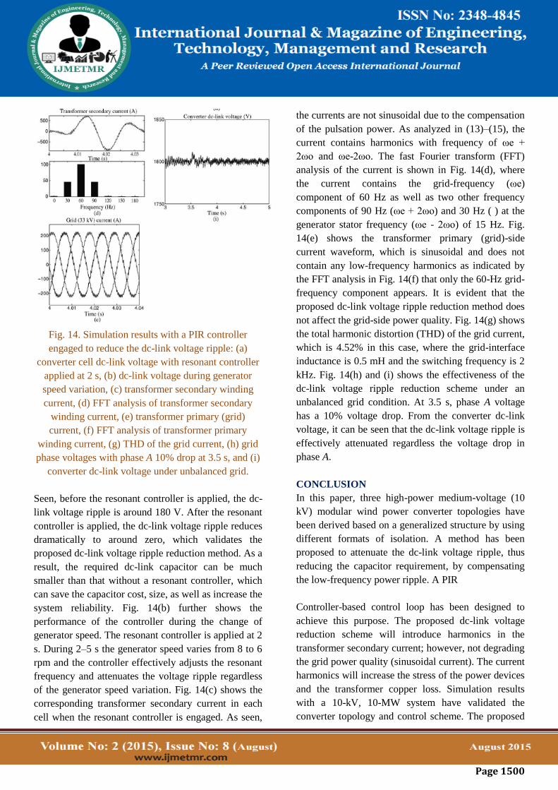
Fig. 14. Simulation results with a PIR controller
engaged to reduce the dc-link voltage ripple: (a)
converter cell dc-link voltage with resonant controller
applied at 2 s, (b) dc-link voltage during generator
speed variation, (c) transformer secondary winding
current, (d) FFT analysis of transformer secondary
winding current, (e) transformer primary (grid)
current, (f) FFT analysis of transformer primary
winding current, (g) THD of the grid current, (h) grid
phase voltages with phase A 10% drop at 3.5 s, and (i)
converter dc-link voltage under unbalanced grid.
Seen, before the resonant controller is applied, the dc-
link voltage ripple is around 180 V. After the resonant
controller is applied, the dc-link voltage ripple reduces
dramatically to around zero, which validates the
proposed dc-link voltage ripple reduction method. As a
result, the required dc-link capacitor can be much
smaller than that without a resonant controller, which
can save the capacitor cost, size, as well as increase the
system reliability. Fig. 14(b) further shows the
performance of the controller during the change of
generator speed. The resonant controller is applied at 2
s. During 2–5 s the generator speed varies from 8 to 6
rpm and the controller effectively adjusts the resonant
frequency and attenuates the voltage ripple regardless
of the generator speed variation. Fig. 14(c) shows the
corresponding transformer secondary current in each
cell when the resonant controller is engaged. As seen,
the currents are not sinusoidal due to the compensation
of the pulsation power. As analyzed in (13)–(15), the
current contains harmonics with frequency of ωe +
2ωo and ωe-2ωo. The fast Fourier transform (FFT)
analysis of the current is shown in Fig. 14(d), where
the current contains the grid-frequency (ωe)
component of 60 Hz as well as two other frequency
components of 90 Hz (ωe + 2ωo) and 30 Hz ( ) at the
generator stator frequency (ωe - 2ωo) of 15 Hz. Fig.
14(e) shows the transformer primary (grid)-side
current waveform, which is sinusoidal and does not
contain any low-frequency harmonics as indicated by
the FFT analysis in Fig. 14(f) that only the 60-Hz grid-
frequency component appears. It is evident that the
proposed dc-link voltage ripple reduction method does
not affect the grid-side power quality. Fig. 14(g) shows
the total harmonic distortion (THD) of the grid current,
which is 4.52% in this case, where the grid-interface
inductance is 0.5 mH and the switching frequency is 2
kHz. Fig. 14(h) and (i) shows the effectiveness of the
dc-link voltage ripple reduction scheme under an
unbalanced grid condition. At 3.5 s, phase A voltage
has a 10% voltage drop. From the converter dc-link
voltage, it can be seen that the dc-link voltage ripple is
effectively attenuated regardless the voltage drop in
phase A.
CONCLUSION
In this paper, three high-power medium-voltage (10
kV) modular wind power converter topologies have
been derived based on a generalized structure by using
different formats of isolation. A method has been
proposed to attenuate the dc-link voltage ripple, thus
reducing the capacitor requirement, by compensating
the low-frequency power ripple. A PIR
Controller-based control loop has been designed to
achieve this purpose. The proposed dc-link voltage
reduction scheme will introduce harmonics in the
transformer secondary current; however, not degrading
the grid power quality (sinusoidal current). The current
harmonics will increase the stress of the power devices
and the transformer copper loss. Simulation results
with a 10-kV, 10-MW system have validated the
converter topology and control scheme. The proposed
Page 1501
dc-link voltage ripple reduction method may also be
used in the other two topologies presented in the paper.
ACKNOWLEDGMENT
The author would like to thank Dr. D. Grant, Visiting
Fellow at the University of Bristol, for his comments
on the paper.
REFERENCES
[1] M. Liserre, R. Cardenas, M. Molinas, and J.
Rodriguez, “Overview of multi- MW wind turbines
and wind parks,” IEEE Trans. Ind. Electron., vol. 58,
no. 4, pp. 1081–1095, Apr. 2011.
[2] F. Blaabjerg, M. Liserre, and K. Ma, “Power
electronics converters for wind turbine systems,” IEEE
Trans. Ind. Appl., vol. 48, no. 2, pp. 708–719,
Mar. 2012.
[3] M. Chinchilla, S. Arnaltes, and J. Burgos, “Control
of permanent-magnet generators applied to variable-
speed wind-energy systems connected to the
grid,” IEEE Trans. Energy Convers., vol. 21, no. 1, pp.
130–135, Mar. 2006.
[4] J. Dai, D. Xu, and B. Wu, “A novel control scheme
for current–source– converter-based PMSG wind
energy conversion systems,” IEEE Trans. Power
Electron., vol. 24, no. 4, pp. 963–972, Apr. 2009.
[5] J. Birk and B. Andresen, “Parallel-connected
converters for optimizing efficiency, reliability and
grid harmonics in a wind turbine,” in Proc. EPE’07
Conf., Aalborg, Denmark, Sep. 2007, pp. 1–7.
[6] Z. Xu, R. Li, H. Zhu, D. Xu, and C. H. Zhang,
“Control of parallel multiple converters for direct-
drive permanent-magnet wind power generation
systems,” IEEE Trans. Power Electron., vol. 27, no. 3,
pp. 1250–1270, Mar. 2012.
[7] W. Erdman and M. Behnke, “Low wind speed
turbine project phase II: The application of medium-
voltage electrical apparatus to the class of variable
speed multi-megawatt low wind speed turbines,” San
Ramon, CA, USA, Natl. Renew. Energy Lab. Rep.,
NREL/SR-500-38686, Nov. 2005.
[8] H. Abu-Rub, J. Holtz, J. Rodriguez, and G.
Baoming, “Medium-voltage multilevel converters-
state of the art, challenges and requirements in
industrial applications,” IEEE Trans. Ind. Electron.,
vol. 57, no. 8, pp. 2581–2596, Aug. 2010.
[9] R. C. Portillo, M. M. Prats, J. I. Leon, J. A.
Sanchez, J. M. Carrasco, E. Galvan et al., “Modelling
strategy for back-to-back three-level converters
applied to high-power wind turbines,” IEEE Trans.
Ind. Electron., vol. 53, no. 5, pp. 1483–1491, Oct.
2006.
[10] E. J. Bueno, S. Cóbreces, F. J. Rodríguez, A.
Hernández, and F. Espinosa, “Design of a back-to-
back NPC converter interface for wind turbines with
Squirrel-cage induction generator,” IEEE Trans.
Energy Convers., vol. 23, no. 3, pp. 932–945, Sep.
2008.
[11] A. Faulstich, J. K. Steinke, and F. Wittwer,
“Medium voltage converter for permanent magnet
wind power generators up to 7 MW,” in Proc. EPE
Conf., Barcelona, Spain, Sep. 2009, pp. 9–17.
[12] C. L. Xia, X. Gu, and Y. Yan, “Neutral-point
potential balancing of three level inverters in direct-
driven wind energy conversion system,” IEEE Trans.
Energy Convers., vol. 26, no. 1, pp. 18–29, Mar. 2011.
[13] M. Winkelnkemper, F. Wildner, and P. K.
Steimer, “6 MVA five-level hybrid converter for wind
power,” in Proc. IEEE PESC’08 Conf., Rhodes,
Greece, Jun. 2008, pp. 4532–4538.
[14] X. Yuan, J. Chai, and Y. Li, “A transformer-less
high-power converter for large permanent magnet
wind generator systems,” IEEE Trans. Sustain.
Energy, vol. 3, no. 3, pp. 318–329, Jul. 2012.

Page 1502
[15] C. Xia, Z. Wang, T. Shi, and Z. Song, “A novel
cascaded boost chopper for the wind energy
conversion system based on the permanent magnet
synchronous generator,” IEEE Trans. Energy
Convers., vol. 28, no. 3, pp. 512–522, Sep. 2013.
[16] C.H. Ng,M. A. Parker, R. Li, P. J. Tavner, J. R.
Bumby, and E. Spooner, “A multilevel modular
converter for a large light weight wind turbine
generator,” IEEE Trans. Power Electron., vol. 23, no.
3, pp. 1062–1074, May 2008.
[17] M. A. Parker, C. H. Ng, and L. Ran, “Fault-
tolerant control for a modular generator converter
scheme for direct drive wind turbines,” IEEE Trans.
Ind. Electron., vol. 58, no. 1, pp. 305–315, Jan. 2011.
[18] J. Kang, N. Takada, E. Yamamoto, and E.
Watanabe, “High power matrix converter for wind
power generation applications,” in Proc. ICPE ECCE
Asia Conf., Jeju, Korea, Jun. 2011, pp. 1331–1336.
[19] M. A. Perez, J. R. Espinoza, J. R. Rodriguez, and
P. Lezana, “Regenerative medium voltage AC drive
based on a multicell arrangement with reduced energy
storage requirements,” IEEE Trans. Ind. Electron., vol.
52, no. 1, pp. 171–180, Feb. 2005.
[20] S. Inoue and H. Akagi, “A bidirectional isolated
dc–dc converter as a core circuit of the next-generation
medium-voltage power conversion system,” IEEE
Trans. Power Electron., vol. 22, no. 2, pp. 535–542,
Mar. 2007.
[21] F. Iov, F. Blaabjerg, J. Clare, O. Wheeler, A.
Rufer, and A. Hyde, “UNIFLEX-PM-A key-enabling
technology for future European electricity networks,”
EPE J., vol. 19, no. 4, pp. 6–16, 2009.
[22] J. Rodriguez, S. Bernet, B. Wu, J. O. Pontt, and S.
Kouro, “Multilevel voltage source converter
topologies for industrial medium-voltage drives,”
IEEE Trans. Ind. Electron., vol. 54, no. 6, pp. 2930–
2945, Dec. 2007.
[23] H. D. Bang, R. P. Roojj, A. S. McDonald, and M.
A. Mueller, “10MWwind turbine direct drive generator
design with pitch or active speed stall control,” in
Proc. IEEE IEMDC Conf., Antalya, Turkey, vol. 2,
May 2007, pp. 1390–1395.
[24] X. Yuan, F. Wang, D. Boroyevich, Y. Li, and R.
Burgos, “Dc-link voltage control of a full power
converter for wind generator operating in weak-grid
systems,” IEEE Trans. Power Electron., vol. 24, no. 9,
pp. 2178–2192, Sep. 2009.
[25] R. Cardenas and R. Pena, “Sensor less vector
control of induction machines for variable-speed wind
energy applications,” IEEE Trans. Energy Convers.,
vol. 19, no. 1, pp. 196–205, Mar. 2004.
[26] P. J. Tavner, G. J. W. Bussel, and F. Spinato,
“Machine and converter reliabilities in wind turbines,”
in Proc. IET PEMD’06 Conf., Dublin, Ireland, Mar.
2006, pp. 127–130.
[27] R. Teodorescu, F. Blaabjerg, M. Liserre, and P. C.
Loh, “Proportional resonant controllers and filters for
grid-connected voltage–source converters,” IEE Proc.
Elect. Power Appl., vol. 153, no. 5, pp. 750–762, Sep.
2006.
[28] R. Teodorescu, M. Liserre, and P. Rodriguez,
Grid Converters for Photovoltaic and Wind Power
Systems, Chap. 4. Hoboken, NJ, USA: Wiley, 2011.
[29] IGBT module datasheet [Online]. Available:
http://www.infineon.com dgdl/
[30] S. Dieckerhoff, S. Bernet, and D. Krug Power,
“Loss-oriented evaluation of high voltage IGBTs and
multilevel converters in transformerless traction
applications,” IEEE Trans. Power Electron., vol. 20,
no. 6, pp. 1328–1336, Nov. 2005.

Page 1503
Author Details
Miss. Sri Nandini Balabommu is pursuing M.Tech
(Power Systems) at Kandula Srinivasa Reddy
Memorial College of Engineering. She Completed her
B.Tech(EEE) from Kottam College of Engineering,
Kurnool, Andhra Pradesh, India.
Mr. Bhaskar Reddy member of IEI and IEEE member
since 2002. He is acting as Secretary IEI Student
Branch. Many IEI student branch activities are being
run successfully under his esteemed Guidance. Areas
of interest: Power systems, Electrical installation &
Estimation(EIE), Power Electronics, Power
Electronics and Drives, High Voltage DC
Transmission and FACTS etc.