medium voltage product keca 80 o135 outdoor current
TRANSCRIPT

— MEDIUM VOLTAGE PRODUC T
KECA 80 O135 Outdoor Current SensorsInstructions for installation, use and maintenance
2 K EC A 8 0 O1 3 5 O UTD O O R CU R R E NT S E N S O R S I NS TR U C TI O NS FO R I NS TA L L ATI O N , USE A N D M A I NTEN A N CE
3 1. Operating conditions3 2. Technical details4 3. Instructions for installation4 Safety instruction4 Installation conditions4 General information4 Checking current sensor upon
arrival4 Preparations before installation5 Activities after the installing5 Safety instructions5 Mounting5 Secondary connections7 Grounding terminal7 4. Instructions for use7 Routine test report 7 5. Instructions for maintenance8 6. Transport and storage8 7. Handling with the sensors8 8. Recommended procedure
for disposal of the sensor9 9. Dimensional Drawing
— Scope of Contents

3
1. Operating conditions
The current sensor can be operated in outdoor conditions where the ambient air may be polluted by dust, smoke, corrosive cases, vapors or salt.
The current sensor is designed for standard am-bient temperature between -50 °C and +80 °C (storage and transportation temperature be-tween -50 °C and +80 °C). The average value of the ambient temperature, measured over a period of 24 hours, should not exceed 40 °C. The altitude for mounting should be lower than 1 000 m above sea level. The current sensor may be used also in higher or lower ambient temperatures and at higher altitudes when agreed upon with the man-ufacturer.
KECA 80 O135 current sensor is suitable for mea-suring phase currents. Where busbar or cable serves as the primary conductor. Can also be used for measuring the phase current at voltages higher than 0.72 kV if the insulation of the primary conductor satisfies the requirements of the re-spective standards for the operating voltage. The Rogowski coil is cast in resin which provides per-fect electrical and mechanical performance. KECA 80 O135 is dedicated to work with the SF6-insu-lated pole mounted switch disconnector type SECTOS. The internal parts are shielded – conduc-tive screening shall be at ground potential. The di-mensions of the KECA 80 O135 are adjusted to the size of the SECTOS bushings.
KECA 80 O135 current sensor complies with the requirements for combined degree of protection provided by enclosures IP 66/IP 68 and degree of protection against external mechanical impacts IK07.
2. Technical details
For sensor dimensions see dimension drawings at the end of these instructions. Rated values for each individual sensor are mentioned on the rat-
ing plate riveted to the sensor. Values mentioned on the rating plate must not be exceeded.
KECA 80 O135 Type code
S/N Serial number Ipr Rated primary current Usr Rated secondary output cl. Accuracy class Kpcr Rated extended primary current factor CFI Correction factors used for current
sensor. Correction factors are measured and calculated separately for each sensor. Amplitude correction factor is a number by which the output signal of the sensor shall be multiplied in order to have minimum amplitude error.
ϕ0 corCorrection factors used for current sensor. Correction factors are measured and calculated separately for each sensor. Phase error correction factor is a number by which the output signal of the sensor shall be increased or decreased (depending on the sign) in order to have minimum phase error.
fr Rated frequency in Hz
Ith/Idyn Rated short-time thermal current in kA / Rated dynamic current in kA
-50/+80 °C Ambient temperature 2.5 kg Weight E Insulation class IEC 61869-10 IEC – standard referred to 18 MAR 2021 Date of production
Tab. 1. Labels abbreviation definitions according to IEC 61869-10
—01 Example of a sensor label according to IEC 61869-10
—Instructions for installation, use and maintenance for the KECA 80 O135 current sensorThese instructions for installation, use and maintenance are valid for KECA 80 O135 current sensor (low-power passive current transformer according to IEC 61869-10 standard) operating in outdoor conditions.
—01
Ipr: 80 A Usr:0.15/0.18 V derivative
IEC 61869-10 Made by ABB 18 MAR 2021 Kpcr: 50 Ith/Idyn: 50(3s)/125 kA 2.5 kg
0.72/3/-//0,82 kV fr: 50/60 Hz -50/80 °C E cl: 0.5/5P630-A2 CFI: 1.0020 o cor: +0.0030°
KECA 80 O135 S/N 1VLT5419001587Current Sensor
SPECIFIKACE:POZADÍ - ČERNÁPÍSMO - BÍLÁ
- LOGO - 24 - Current sensor - ARIAL 14 - OSTATNÍ - ARIAL 8 TUČNĚ
HLINÍKOVÝ ŠTÍTEK
SPECIFICATION:BACKGROUND - BLACKLETTERS - WHITE
- LOGO - 24 - Current sensor - ARIAL 14 - OTHERS - ARIAL 8 BOLT
ALUMINUM PLATE
NAMEPLATE DRAWING 1VL4900517P0001VÝKRES ŠTÍTKU 1VL4900517P0001
Příklad dat uložených v 2D kódu:Example of data stored in 2D Bar Code:
RevisionsZone Rev. Description Date
A
2021-04-15
1 / 1
P. VelesikCZ-BRQ
CZABBA.004 2:1
A4
KECA 80 O135
.
.... . TYPOVÝ HLINÍKOVÝ ŠTÍTEK
SENZORU KECA 80 O135
SENSOR ALUMINUM NAMEPLATE KECA 80 O135
Sheet No.
Format
Language
Scale
Subtitle
Type Derived from
NameDateLocation
Revision
Drawn
Checked
Approved
EC No.
EN
DraftDrawing status
Title
Drawing No.
Responsible
2RKA026349A0001
Not applicableWeightMaterial
fm
cv
HL
KX X..
..
PRO
PRIE
TAR
Y AN
D S
ECR
ET IN
FOR
MAT
ION
The
info
rmat
ion
cont
aine
d in
this
doc
umen
t has
to b
e ke
pt s
trict
ly c
onfid
entia
l.An
y un
auth
oriz
ed u
se, r
epro
duct
ion,
dis
tribu
tion
or d
iscl
osur
e to
third
par
ties
is s
trict
ly fo
rbid
den.
ABB
rese
rves
all
right
s re
gard
ing
Inte
llect
ual P
rope
rty R
ight
s.Th
read
Qua
lity
Tole
ranc
e "6
g-6H
" ISO
965
.
SurfaceSurface code
Coo
rd. p
unch
ing
N.C
.Mac
h.an
d un
fold
JS1
1
IP C
lass
0
4
2 31 4
A
B
C
D
E
F
A
1 2 3
B
© C
opyr
ight
AB
B. A
ll rig
hts
rese
rved
.20
16
Stan
dard
Tol
eran
ces
for M
achi
ning
and
For
min
g IS
O 2
768-
1,2
Leng
hts
and
Angl
e
Geo
met
rical
Tol
eran
ces
Bend
ed c
onst
ruct
ion
dim
ensi
ons:
"c
"An
gles
of b
endi
ng:
"v"
ABB Switzerland LtdGroup Technology Management
C
4 K EC A 8 0 O1 3 5 O UTD O O R CU R R E NT S E N S O R S I NS TR U C TI O NS FO R I NS TA L L ATI O N , USE A N D M A I NTEN A N CE
3. Instructions for installation
Safety instruction Always ground the sensor grounding terminal.
Installation conditions The sensor can be installed in outdoor conditions. The temperature during the assembly must be between 0°C and +40°C. The sensor cable should not be moved or bent if the temperature is be-low 0°C. The minimal bending radius for the cable is 34 mm. If cable or ferrules is damaged please contact the manufacturer for instructions.
General informationA sensor is a piece of electrical equipment and its electrical installation shall be done by skilled per-son only. Observe the provisions of local legisla-tion regarding the minimum age and the compe-tence criteria for personnel working with or in vicinity of electrical installations. If local legisla-tion is not applicable, the guidelines set forth in EN 50110-1 shall be observed.
Checking current sensor upon arrivalInspection shall be made upon arrival of current sensor for any signs of damage or tampering in-curred during shipment. If the product has been damaged, or current sensor ratings do not com-ply with order specification, notify the carrier and contact the current sensor manufacturer. Keep the written record of damages until complaint resolution.
Attention: Make sure that current sensor param-eters indicated on the rating plate comply with the parameters specified on the order!
Preparations before installation of current sen-sorsPerform a visual inspection of the current sensor prior to installation paying particular attention to the following points:• cast resin (enclosure) is in good condition,• current sensor terminals and surfaces of hous-
ing and plate are clean and without visible me-chanical damages,
• there are no signs of moisture on the current sensor; in case of visible signs of moisture, the sensor must be dried,
• current sensor ratings comply with technical specification of connection.
The following measurements can be performed before installation:• electric withstand of insulation test under the
test voltage in accordance with requirements of standard specifications given in the catalogue, but value of supplied voltage can not exceed 90 % of the test voltage (it is 738 V). For tests with a higher withstand voltage (e.g. accord-ing to IEC 62271-1,-103), the KECA 80 O135 cur-rent sensor must be disconnected.
• the measurement of the insulation resistance of a secondary winding (towards the ground) us-ing a varindor ohmmeter of the voltage 1 000 V DC. The resistance value can not be less than 100 MΩ.
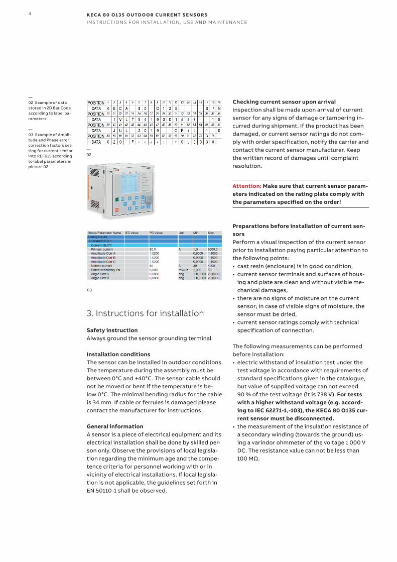
—02 Example of data stored in 2D Bar Code according to label pa-rameters
—03 Example of Ampli-tude and Phase error correction factors set-ting for current sensor into REF615 according to label parameters in picture 02
—02
Ipr: 80 A Usr:0.15/0.18 V derivative
IEC 61869-10 Made by ABB 15 JUL 2019 Ith/Idyn: 50(3s)/125 kA Kpcr: 50 2.5 kg
0.72/3/-//0,82 kV fr: 50/60 Hz -50/80 °C E cl: 0.5/5P630-A3 CFI: 1.0020 o cor: +0.0030°
KECA 80 O135 S/N 1VLT5419001587
Current Sensor
SPECIFIKACE:POZADÍ - ČERNÁPÍSMO - BÍLÁ
- LOGO - 18 - Current sensor - ARIAL 10 - OSTATNÍ - ARIAL 7 TUČNĚ
HLINÍKOVÝ ŠTÍTEK
SPECIFICATION:BACKGROUND - BLACKLETTERS - WHITE
- LOGO - 18 - Current sensor - ARIAL 10 - OTHERS - ARIAL 7 BOLT
ALUMINUM PLATE
NAMEPLATE DRAWING 1VL4900517P0001VÝKRES ŠTÍTKU 1VL4900517P0001
Příklad dat uložených v 2D kódu:Example of data stored in 2D Bar Code:
RevisionsZone Rev. Description Date
A
2021-03-04
1 / 1
P. VelesikCZ-BRQ
CZABBA.002 2:1
A4
KECA 80 O135
.
.... . TYPOVÝ HLINÍKOVÝ ŠTÍTEK
SENZORU KECA 80 O135
SENSOR ALUMINUM NAMEPLATE KECA 80 O135
Sheet No.
Format
Language
Scale
Subtitle
Type Derived from
NameDateLocation
Revision
Drawn
Checked
Approved
EC No.
EN
DraftDrawing status
Title
Drawing No.
Responsible
2RKA026349A0001
Not applicableWeightMaterial
fm
cv
HL
KX X..
..
PR
OP
RIE
TA
RY
AN
D S
EC
RE
T IN
FO
RM
AT
ION
The
info
rmat
ion
cont
aine
d in
this
doc
umen
t has
to b
e ke
pt s
tric
tly c
onfid
entia
l.A
ny u
naut
horiz
ed u
se, r
epro
duct
ion,
dis
trib
utio
n or
dis
clos
ure
to th
ird p
artie
s is
str
ictly
forb
idde
n. A
BB
res
erve
s al
l rig
hts
rega
rdin
g In
telle
ctua
l Pro
pert
y R
ight
s.T
hrea
d Q
ualit
y T
oler
ance
"6
g-6H
" IS
O 9
65.
SurfaceSurface code
Coo
rd. p
unch
ing
N.C
.Mac
h.an
d un
fold
JS
11
IP C
lass
0
4
2 31 4
A
B
C
D
E
F
A
1 2 3
B
© C
opyr
ight
A
BB
. All
right
s re
serv
ed.
2016
Sta
nd
ard
To
lera
nce
s fo
r M
ach
inin
g a
nd
Fo
rmin
g IS
O 2
768-
1,2
Leng
hts
and
Ang
le
Geo
met
rical
Tol
eran
ces
Ben
ded
cons
truc
tion
dim
ensi
ons:
"
c"A
ngle
s of
ben
ding
:
"
v"
ABB Switzerland LtdGroup Technology Management
C
—03
5
Activities after the installing of the sensor and before bringing it into operationAfter the sensor has been installed there have to be made listed inspections:• visual inspection,• checking of proper installing (use of all holes for
fixing, proper holding down of fixing bolts),• checking of proper grounding of terminal.
Safety instructions1. Installed current sensor shall be always consid-
ered as part of interconnected circuit. Never at-tempt to touch the leads, terminals or other parts of the current sensor unless they are known to be properly connected and ground.
2. Always ground the metal plate of sensor.3. A sensor cable not connected in the junction
box can be left open or short-circuited without any harm for the sensor. The same applies to the connecting cable leading to the IED from the junction box. Even during a primary short-circuit the voltage in the secondary cir-cuit of the current sensor will be below 100 V. Nevertheless it is a good safety practice to earth cables of sensors not connected to the junction box or if connecting cables are discon-nected.
Attention: Maintenance of the sensors should be done in accordance with the safety and occupa-tional hygiene requirements for electrical equip-ment.
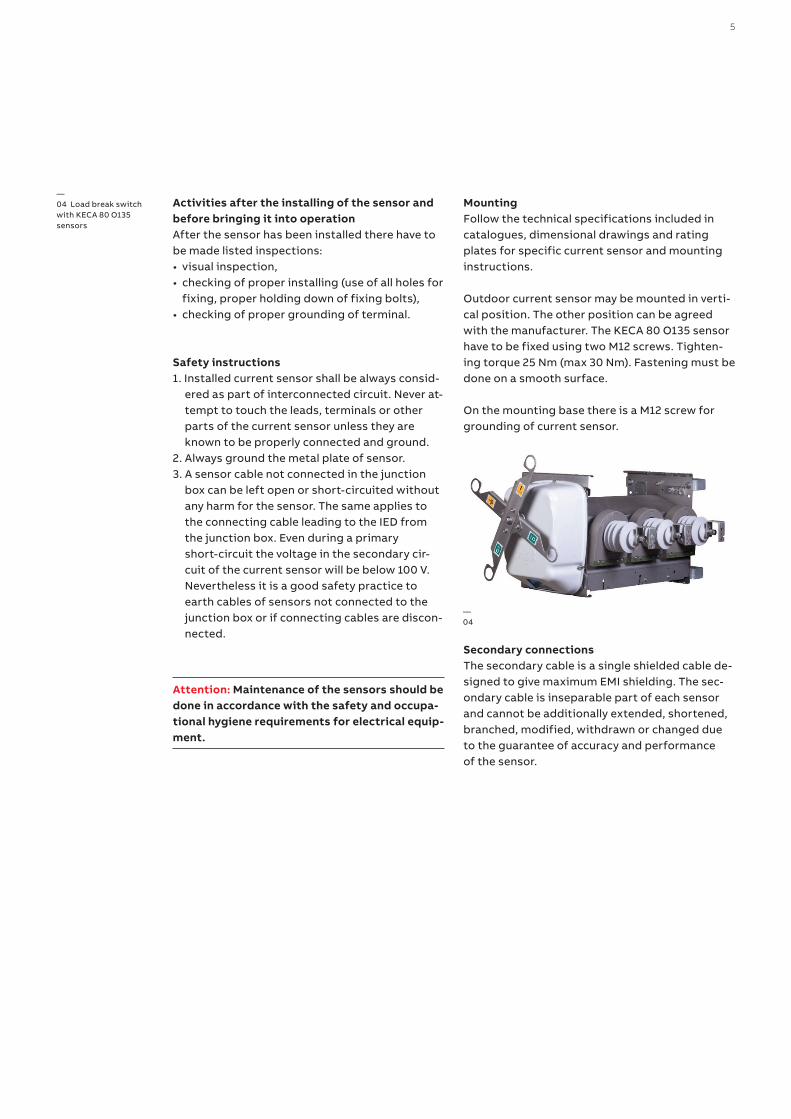
MountingFollow the technical specifications included in catalogues, dimensional drawings and rating plates for specific current sensor and mounting instructions.
Outdoor current sensor may be mounted in verti-cal position. The other position can be agreed with the manufacturer. The KECA 80 O135 sensor have to be fixed using two M12 screws. Tighten-ing torque 25 Nm (max 30 Nm). Fastening must be done on a smooth surface.
On the mounting base there is a M12 screw for grounding of current sensor.
Secondary connectionsThe secondary cable is a single shielded cable de-signed to give maximum EMI shielding. The sec-ondary cable is inseparable part of each sensor and cannot be additionally extended, shortened, branched, modified, withdrawn or changed due to the guarantee of accuracy and performance of the sensor.
—04 Load break switch with KECA 80 O135 sensors
—04
6 K EC A 8 0 O1 3 5 O UTD O O R CU R R E NT S E N S O R S I NS TR U C TI O NS FO R I NS TA L L ATI O N , USE A N D M A I NTEN A N CE
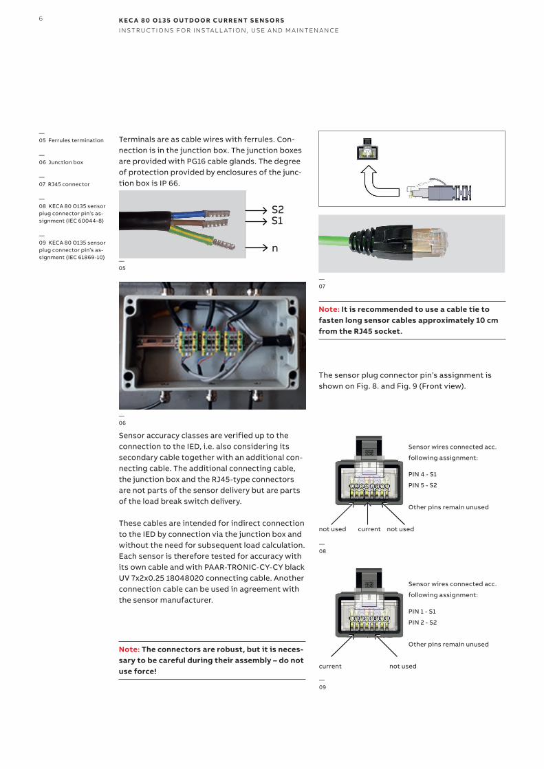
Terminals are as cable wires with ferrules. Con-nection is in the junction box. The junction boxes are provided with PG16 cable glands. The degree of protection provided by enclosures of the junc-tion box is IP 66.
Sensor accuracy classes are verified up to the connection to the IED, i.e. also considering its secondary cable together with an additional con-necting cable. The additional connecting cable, the junction box and the RJ45-type connectors are not parts of the sensor delivery but are parts of the load break switch delivery.
These cables are intended for indirect connection to the IED by connection via the junction box and without the need for subsequent load calculation. Each sensor is therefore tested for accuracy with its own cable and with PAAR-TRONIC-CY-CY black UV 7x2x0.25 18048020 connecting cable. Another connection cable can be used in agreement with the sensor manufacturer.
Note: The connectors are robust, but it is neces-sary to be careful during their assembly – do not use force!
Note: It is recommended to use a cable tie to fasten long sensor cables approximately 10 cm from the RJ45 socket.
The sensor plug connector pin’s assignment is shown on Fig. 8. and Fig. 9 (Front view).
—06
S2
—05
—05 Ferrules termination
—06 Junction box
—07 RJ45 connector
—08 KECA 80 O135 sensor plug connector pin’s as-signment (IEC 60044-8)
—09 KECA 80 O135 sensor plug connector pin’s as-signment (IEC 61869-10)
—07
—08
not used current not used
Sensor wires connected acc.
following assignment:
PIN 4 - S1
PIN 5 - S2
Other pins remain unused
—09
current not used
Sensor wires connected acc.
following assignment:
PIN 1 - S1
PIN 2 - S2
Other pins remain unused
S1
n
7
A cable not connected to the IED can be left open or short-circuited without any harm for the sen-sor. Even during a primary short-circuit the volt-age in the secondary circuit of the current sensor will be below 100 V. Nevertheless it is a good safety practice to earth cables not connected to the IED. RJ45 plug connector has 8 contacts and locking latch coupling. The sensor connector plug shall be inserted properly with the IED matting re-ceptacle before completing the coupling with the bayonet lock. Take care and do not use excessive force to plug-in and plug-out these connectors.
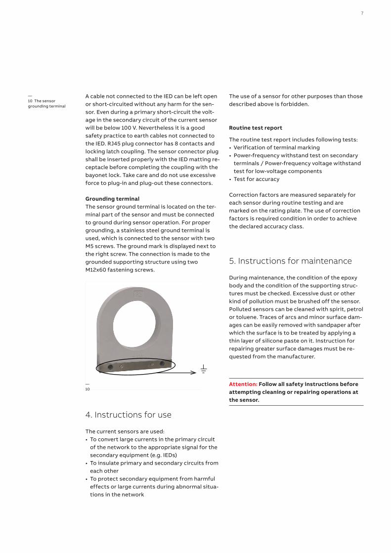
Grounding terminalThe sensor ground terminal is located on the ter-minal part of the sensor and must be connected to ground during sensor operation. For proper grounding, a stainless steel ground terminal is used, which is connected to the sensor with two M5 screws. The ground mark is displayed next to the right screw. The connection is made to the grounded supporting structure using two M12x60 fastening screws.
4. Instructions for use
The current sensors are used:• To convert large currents in the primary circuit
of the network to the appropriate signal for the secondary equipment (e.g. IEDs)
• To insulate primary and secondary circuits from each other
• To protect secondary equipment from harmful effects or large currents during abnormal situa-tions in the network
The use of a sensor for other purposes than those described above is forbidden.
Routine test report
The routine test report includes following tests:• Verification of terminal marking• Power-frequency withstand test on secondary
terminals / Power-frequency voltage withstand test for low-voltage components
• Test for accuracy Correction factors are measured separately for each sensor during routine testing and are marked on the rating plate. The use of correction factors is required condition in order to achieve the declared accuracy class.
5. Instructions for maintenance
During maintenance, the condition of the epoxy body and the condition of the supporting struc-tures must be checked. Excessive dust or other kind of pollution must be brushed off the sensor. Polluted sensors can be cleaned with spirit, petrol or toluene. Traces of arcs and minor surface dam-ages can be easily removed with sandpaper after which the surface is to be treated by applying a thin layer of silicone paste on it. Instruction for repairing greater surface damages must be re-quested from the manufacturer.
Attention: Follow all safety instructions before attempting cleaning or repairing operations at the sensor.
—10 The sensor grounding terminal
—10
8 K EC A 8 0 O1 3 5 O UTD O O R CU R R E NT S E N S O R S I NS TR U C TI O NS FO R I NS TA L L ATI O N , USE A N D M A I NTEN A N CE
6. Transport and storage
The permissible transport and storage tempera-ture for sensors is from -50 to +80 °C. During transport and storage the sensors must be pro-tected against direct sunshine. Sensor assigned for export are delivered packed into wooden boxes or transport pallets.
Sensors should be shipped in the position accord-ing to symbols and marks indicated on its pack-ing case and protected against weather condi-tions. They should be stored in dry and clean places, protected from direct exposure to precipi-tation and solar radiation.
7. Handling with the sensors
Sensors are possible to handle by hands. The sen-sor can be manipulated by grasping the epoxy body. Do not handle the sensor using the cable. Always use the gloves in case of manual handling.
Attention: During the manipulation with sensor is necessary to follow safety work instructions. Never stay under the place where the sensor is handled. Always make sure that the sensor is safely secured against falling.
8. Recommended procedure for disposal of the sensor
The sensor does not contain environmentally haz-ardous materials. For disposal of the product af-ter it has been taken out of use, local regulations, if there are any, should be followed.
9
45
400 + 200 150 ±0,5
14
125
2x14
14,
3
210
20
+ 5 0
20 + 50
25
+ 5 0
10
10 RATING PLATETYPOVÝ ŠTÍTEK
S2 - BLUE WIRE WITH FERRULE / MODRÝ VODIČ S DUTINKOUS1 - BROWN WIRE WITH FERRULE / HNĚDÝ VODIČ S DUTINKOU
GREEN-YELOW SHIELDING WIRE WITH FERRULE / ZELENOŽLUTÝ STÍNÍCÍ VODIČ S DUTINKOU
13
5 ±0,5
230
R105
90
14
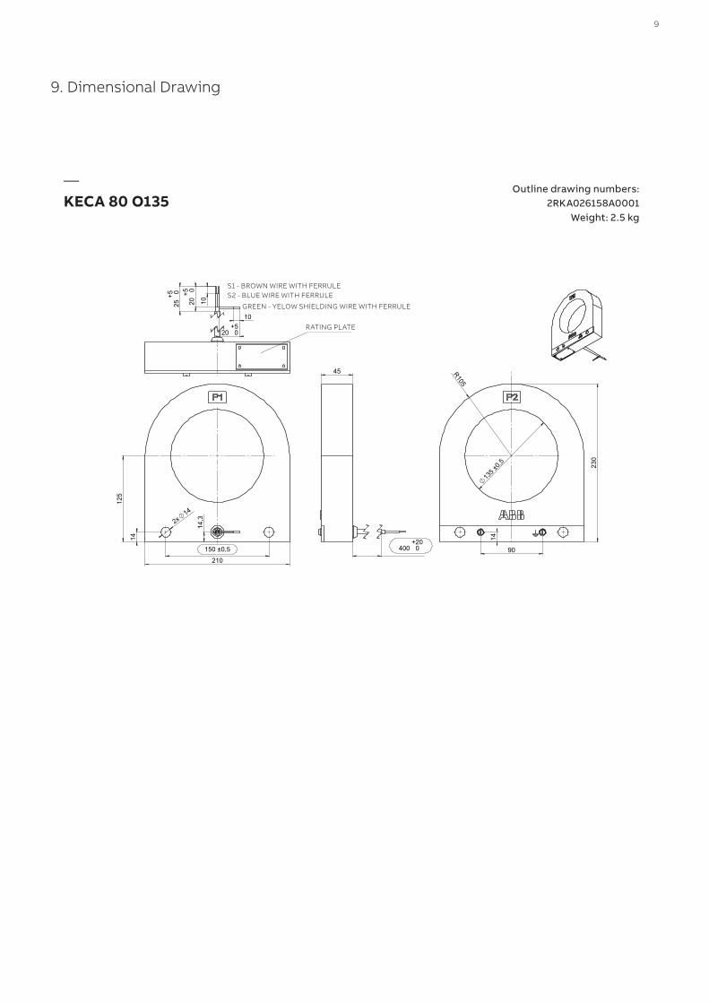
—KECA 80 O135
Outline drawing numbers: 2RKA026158A0001
Weight: 2.5 kg
9. Dimensional Drawing
S1 - BROWN WIRE WITH FERRULES2 - BLUE WIRE WITH FERRULE
GREEN - YELOW SHIELDING WIRE WITH FERRULE
RATING PLATE
1VLM
00
08
16 R
ev.-
, en
20
21.0
5.1
1
—N O T EWe reserve the right to make technical changes or modify the contents of this docu-ment without prior notice. With regard to purchase orders, the agreed particulars shall prevail. ABB does not accept any responsibil-ity whatsoever for potential errors or possi-ble lack of information in this document.
We reserve all rights in this document and in the subject matter and illustrations con-tained therein. Any reproduction, disclosureto third parties or utilization of its contents - in whole or in parts - is forbidden without prior written consent of ABB.
Copyright© 2021 ABBAll rights reserved
—C O N TA C T U SABB s.r.o.ELDS BrnoVidenska 117, 619 00 Brno, Czech Republic Tel.: +420 547 152 021 +420 547 152 854 Fax: +420 547 152 626 E-mail: [email protected]
www.abb.com