medium voltage products v-contact vsc medium voltage ... · v-contact vsc medium voltage vacuum...
TRANSCRIPT
Medium voltage products
V-Contact VSCMedium voltage vacuum contactors
2
V-Contact VSCMedium voltage vacuum contactors
General characteristics Ref. to IEC 62271-106 Standard
VSC 7 - VSC 7/F - VSC 7/G - VSC 7/PVSC 7/PN - VSC 7/PG - VSC 7/PNG
VSC 12 - VSC 12/F - VSC 12/G VSC 12/P - VSC 12/PN - VSC 12/PGVSC S/G - VSC S/F - VSC S/PG VSC S/PNG
Contactor Starter Combined with fuses Contactor Starter Combined with fuses
3.4.105 3.4.110 3.4.110.5 3.4.105 3.4.110 3.4.110.5
Rated voltage [kV] 4.1 7,2 7,2 7,2 12 12 12
Rated insulation voltage [kV] – 7,2 7,2 7,2 12 12 12
Power Frequency Withstand voltage at 50 Hz [kV] 6.2 20 (5) 20 (5) 20 (5) 28 (1) 28 (1) 28 (1)
Impulse withstand voltage [kVbil] 6.2 60 60 60 75 75 75
Rated frequency [Hz] 4.3 50-60 50-60 50-60 50-60 50-60 50-60
Rated service current [A] 4.101 400 400 – (2) 400 (4) 400 (4) – (2)
Short-time withstand current for 1 s [A] 6.6 6,000 6,000 6,000 6,000 6,000 6,000
Rated peak current [kA] 6.6 15 15 15 15 15 15
Breaking capacity up to [kA] 4.107 – – 50 (3) – – 50 (3)
Short-circuit making capacity up to [kA] 4.107 – – 50 (3) – – 50 (3)
Number of operations (rated values)
Contactor DCO [op./hour] 4.102.2 1,200 1,200 1,200 1,200 1,200 1,200
Contactor SCO [op./hour] 4.102.2 1,200 1,200 1,200 1,200 1,200 1,200
Maximum rated admissible overcurrent for ½ period (peak value) [kAp] - 55 – – 55 – –
(Category AC4) 100 closing operations [A] 6.102.4 4,000 4,000 4,000 4,000 4,000 4,000
(Category AC4) 25 opening operations [A] 6.102.5 4,000 4,000 4,000 4,000 4,000 4,000
Rated voltage of the switching devices and auxiliary circuits 4.8,4.9
Feeder type 1: 24÷60 V dc (basic version) – • • • • • •
Feeder type 2: 24÷60 V dc (full option version) – • • • • • •
Feeder type 3: 110÷250 V ac/dc (basic version) – • • • • • •
Feeder type 4: 110÷250 V ac/dc (full option version) – • • • • • •
Normal current [A] 4.4.101 400 400 – (2) 400 400 – (2)
Mechanical life
VSCnumber of cycles
6.101
1,000,000 1,000,000 1,000,000 1,000,000 1,000,000 1,000,000
number of operations 2,000,000 2,000,000 2,000,000 2,000,000 2,000,000 2,000,000
VSC-Snumber of cycles 400,000 400,000 400,000 400,000 400,000 400,000
number of operations 200,000 200,000 200,000 200,000 200,000 200,000
Apparatus wear classification (type) 4.107.3 C C C C C –
Short-circuit breaking capacity (O-3min-CO-3min-CO) [A] 6.104 5,000 5,000 – 5,000 5,000 –
Short-circuit making capacity (O-3min-CO-3min-CO) [A peak] 6.104 13,000 13,000 – 13,000 13,000 –
Switching timesOpening time (lower and upper limit) [ms] – 35...60 35...60 35...60 35...60 35...60 35...60
Closing time (lower and upper limit) [ms] – 60...90 60...90 60...90 60...90 60...90 60...90
Tropicalisation (IEC 721-2-1) – • • • • • •
(1) Version for 42 kV 50 Hz x 1 min. between phases and between phase and earth available on request - (only VSC12/G contactors without fuseholders and withdrawable VSC12/PG for UniGear panels I = 650 mm).
(2) Depending on the capacity of the coordinated fuse.(3) Value linked to the breaking capacity of the fuse: refer to the fuse manufacturer’s documentation.(4) Not applicabile for VSC-S versions.(5) Version with 32 kV -50Hz x 1 min between phases and between phase and earth available on
request - (only VSC7/G contactors without fuseholders, withdrawable VSC7/PG for UniGear panels I = 650 mm and VSC7/PNG for UniGear MCC).
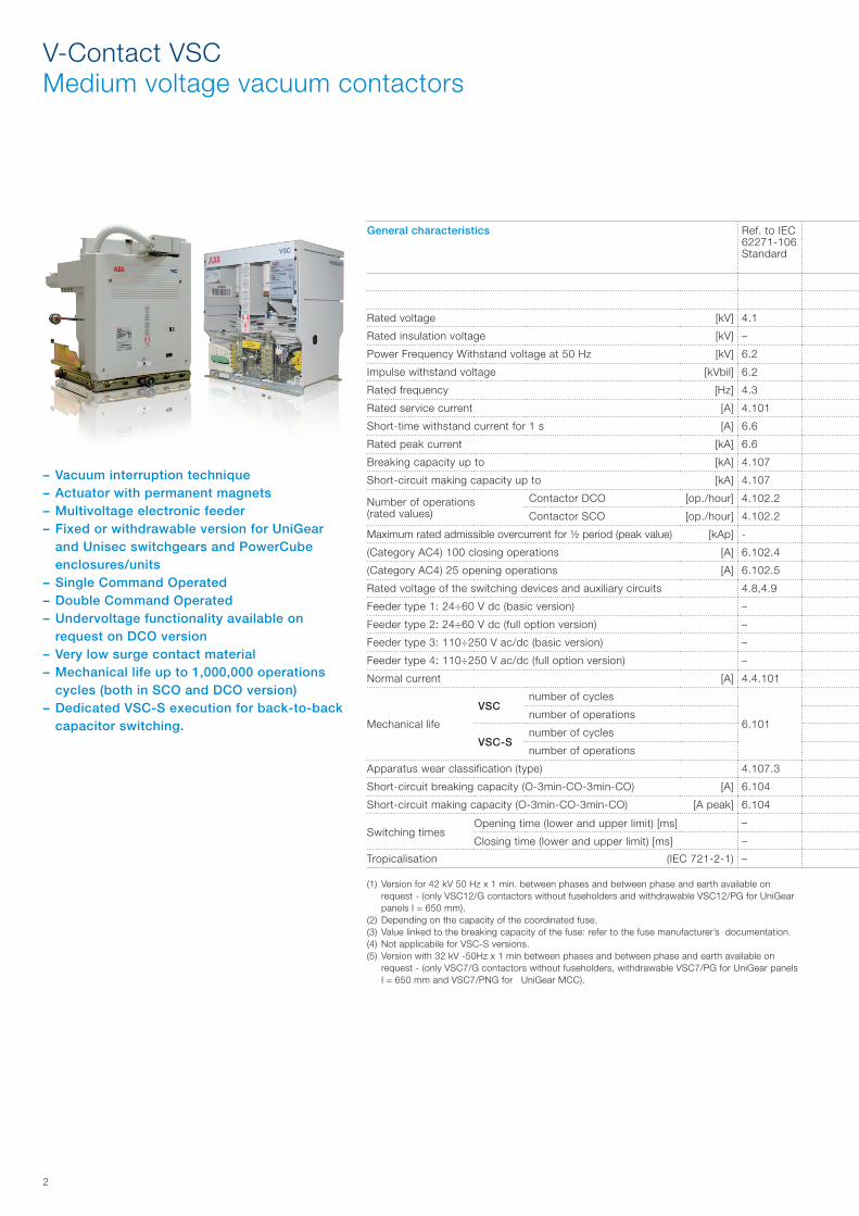
– Vacuum interruption technique– Actuator with permanent magnets– Multivoltage electronic feeder– Fixed or withdrawable version for UniGear
and Unisec switchgears and PowerCube enclosures/units
– Single Command Operated– Double Command Operated – Undervoltage functionality available on
request on DCO version– Very low surge contact material– Mechanical life up to 1,000,000 operations
cycles (both in SCO and DCO version)– Dedicated VSC-S execution for back-to-back
capacitor switching.
3
General characteristics Ref. to IEC 62271-106 Standard
VSC 7 - VSC 7/F - VSC 7/G - VSC 7/PVSC 7/PN - VSC 7/PG - VSC 7/PNG
VSC 12 - VSC 12/F - VSC 12/G VSC 12/P - VSC 12/PN - VSC 12/PGVSC S/G - VSC S/F - VSC S/PG VSC S/PNG
Contactor Starter Combined with fuses Contactor Starter Combined with fuses
3.4.105 3.4.110 3.4.110.5 3.4.105 3.4.110 3.4.110.5
Rated voltage [kV] 4.1 7,2 7,2 7,2 12 12 12
Rated insulation voltage [kV] – 7,2 7,2 7,2 12 12 12
Power Frequency Withstand voltage at 50 Hz [kV] 6.2 20 (5) 20 (5) 20 (5) 28 (1) 28 (1) 28 (1)
Impulse withstand voltage [kVbil] 6.2 60 60 60 75 75 75
Rated frequency [Hz] 4.3 50-60 50-60 50-60 50-60 50-60 50-60
Rated service current [A] 4.101 400 400 – (2) 400 (4) 400 (4) – (2)
Short-time withstand current for 1 s [A] 6.6 6,000 6,000 6,000 6,000 6,000 6,000
Rated peak current [kA] 6.6 15 15 15 15 15 15
Breaking capacity up to [kA] 4.107 – – 50 (3) – – 50 (3)
Short-circuit making capacity up to [kA] 4.107 – – 50 (3) – – 50 (3)
Number of operations (rated values)
Contactor DCO [op./hour] 4.102.2 1,200 1,200 1,200 1,200 1,200 1,200
Contactor SCO [op./hour] 4.102.2 1,200 1,200 1,200 1,200 1,200 1,200
Maximum rated admissible overcurrent for ½ period (peak value) [kAp] - 55 – – 55 – –
(Category AC4) 100 closing operations [A] 6.102.4 4,000 4,000 4,000 4,000 4,000 4,000
(Category AC4) 25 opening operations [A] 6.102.5 4,000 4,000 4,000 4,000 4,000 4,000
Rated voltage of the switching devices and auxiliary circuits 4.8,4.9
Feeder type 1: 24÷60 V dc (basic version) – • • • • • •
Feeder type 2: 24÷60 V dc (full option version) – • • • • • •
Feeder type 3: 110÷250 V ac/dc (basic version) – • • • • • •
Feeder type 4: 110÷250 V ac/dc (full option version) – • • • • • •
Normal current [A] 4.4.101 400 400 – (2) 400 400 – (2)
Mechanical life
VSCnumber of cycles
6.101
1,000,000 1,000,000 1,000,000 1,000,000 1,000,000 1,000,000
number of operations 2,000,000 2,000,000 2,000,000 2,000,000 2,000,000 2,000,000
VSC-Snumber of cycles 400,000 400,000 400,000 400,000 400,000 400,000
number of operations 200,000 200,000 200,000 200,000 200,000 200,000
Apparatus wear classification (type) 4.107.3 C C C C C –
Short-circuit breaking capacity (O-3min-CO-3min-CO) [A] 6.104 5,000 5,000 – 5,000 5,000 –
Short-circuit making capacity (O-3min-CO-3min-CO) [A peak] 6.104 13,000 13,000 – 13,000 13,000 –
Switching timesOpening time (lower and upper limit) [ms] – 35...60 35...60 35...60 35...60 35...60 35...60
Closing time (lower and upper limit) [ms] – 60...90 60...90 60...90 60...90 60...90 60...90
Tropicalisation (IEC 721-2-1) – • • • • • •
4
V-Contact VSCMedium voltage vacuum contactors
D
H
W
D
H
W
General characteristics
Ultimate performances for (value refers to fixed versions without fuseholder)
VSC 7 - 400A (6) VSC 12 - 400 A (6)
Rated voltage [kV] 2,2/2,5 3,3 3,6/5 6,2/7,2 12
Motors [kW] 1,000 1,500 1,500 3,000 5,000
Transformers [kVA] 1,100 1,600 2,000 4,000 5,000
Capacitors (only for VSC-S versions) [kVAr] 1,000 1,500 1,500 3,000 4,800
Ultimate performances for back-to-back capacitor banks
VSC-S/G - VSC-S/F - VSC-S/PG - VSC-S/PNG
Rated voltage [kA] 2,2/2,5 3,3 3,6/5 6,2/7,2 12
Rated current [A] 250 250 250 250 250
Maximum transient current of the capacitor [kA] 8 8 8 8 8
Maximum transient frequency of capacitor connection [kHz] 2,5 2,5 2,5 2,5 2,5
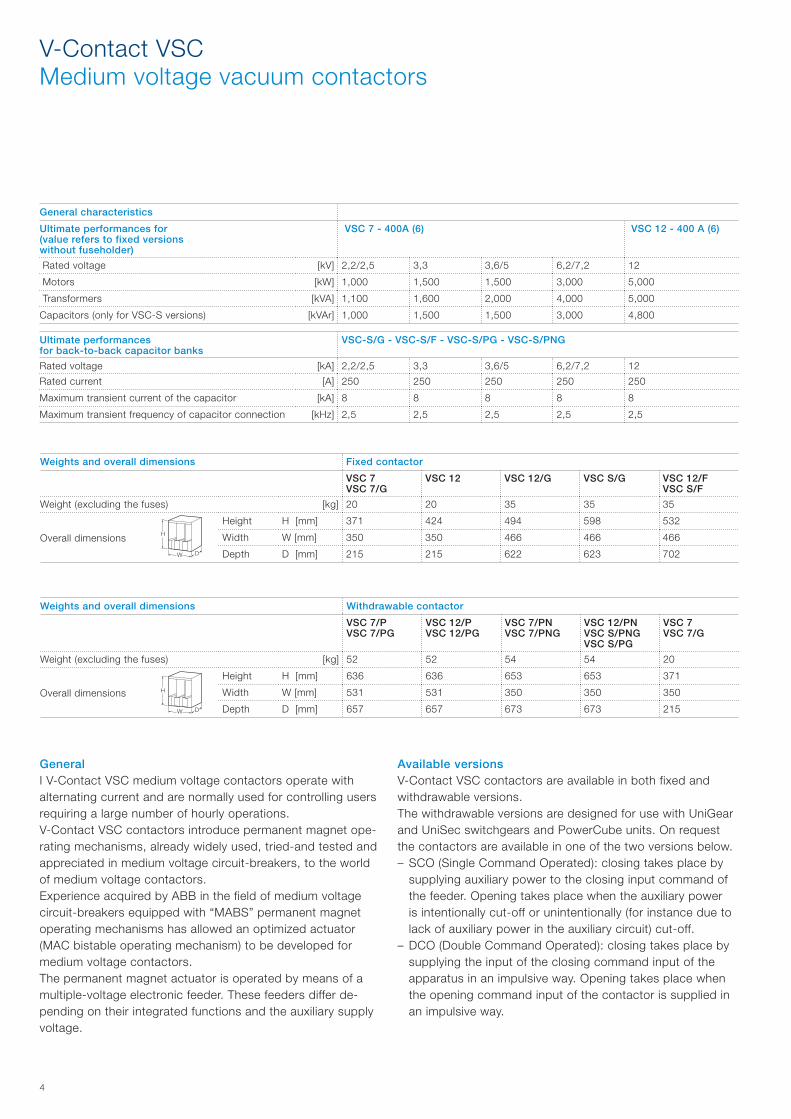
Weights and overall dimensions Fixed contactor
VSC 7VSC 7/G
VSC 12 VSC 12/G VSC S/G VSC 12/FVSC S/F
Weight (excluding the fuses) [kg] 20 20 35 35 35
Overall dimensions
Height H [mm] 371 424 494 598 532
Width W [mm] 350 350 466 466 466
Depth D [mm] 215 215 622 623 702
Weights and overall dimensions Withdrawable contactor
VSC 7/PVSC 7/PG
VSC 12/PVSC 12/PG
VSC 7/PNVSC 7/PNG
VSC 12/PNVSC S/PNGVSC S/PG
VSC 7VSC 7/G
Weight (excluding the fuses) [kg] 52 52 54 54 20
Overall dimensions
Height H [mm] 636 636 653 653 371
Width W [mm] 531 531 350 350 350
Depth D [mm] 657 657 673 673 215
GeneralI V-Contact VSC medium voltage contactors operate with alternating current and are normally used for controlling users requiring a large number of hourly operations.V-Contact VSC contactors introduce permanent magnet ope-rating mechanisms, already widely used, tried-and tested and appreciated in medium voltage circuit-breakers, to the world of medium voltage contactors.Experience acquired by ABB in the field of medium voltage circuit-breakers equipped with “MABS” permanent magnet operating mechanisms has allowed an optimized actuator (MAC bistable operating mechanism) to be developed for medium voltage contactors.The permanent magnet actuator is operated by means of a multiple-voltage electronic feeder. These feeders differ de-pending on their integrated functions and the auxiliary supply voltage.
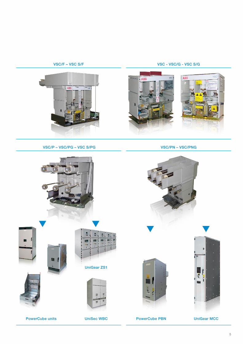
Available versions V-Contact VSC contactors are available in both fixed and withdrawable versions.The withdrawable versions are designed for use with UniGear and UniSec switchgears and PowerCube units. On request the contactors are available in one of the two versions below.– SCO (Single Command Operated): closing takes place by
supplying auxiliary power to the closing input command of the feeder. Opening takes place when the auxiliary power is intentionally cut-off or unintentionally (for instance due to lack of auxiliary power in the auxiliary circuit) cut-off.
– DCO (Double Command Operated): closing takes place by supplying the input of the closing command input of the apparatus in an impulsive way. Opening takes place when the opening command input of the contactor is supplied in an impulsive way.
5
VSC/F – VSC S/F
VSC/P – VSC/PG – VSC S/PG
PowerCube PBNPowerCube units
UniGear ZS1
UniGear MCCUniSec WBC
VSC - VSC/G - VSC S/G
VSC/PN – VSC/PNG
6
C
G
A H
I
BE
F
D
V-Contact VSCMedium voltage vacuum contactors
Feeders The feeder is available in the “Standard” or “Full option” versions. “Basic version” provide internal watchdog, ready to operate condition indication, control of continuity of the internal wiring, check of voltage level of the capacitor.
Auxiliary supply voltageStart up (1) After close operation After open operation Continuous power
consumption 6 sec 1,2 sec 1,2 sec
24…250 V c.c.35 W 25 W 30 W 5 W
110...250 V c.a.
(1) Value applicable to a fully discharged capacitor condition.
Power required from contactor auxiliary circuits
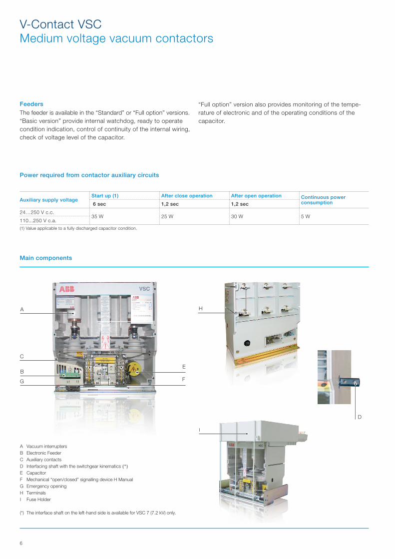
A Vacuum interruptersB Electronic FeederC Auxiliary contactsD Interfacing shaft with the switchgear kinematics (*)
E CapacitorF Mechanical “open/closed” signalling device H ManualG Emergency openingH TerminalsI Fuse Holder
(*) The interface shaft on the left-hand side is available for VSC 7 (7.2 kV) only.
Main components
“Full option” version also provides monitoring of the tempe-rature of electronic and of the operating conditions of the capacitor.

7
Notes
1VC
P00
0616
- R
ev.
– -
en -
Lea
flet
- 20
16.0
2 (V
SC
) (gs
)The data and illustrations are not binding. We reserve the right to make changes without notice in the course of technical development of the product.
© Copyright 2016 ABB. All rights reserved.
Contact us
For more information please contact:
ABB S.p.A.Electrification Products DivisionMedium Voltage ProductsVia Friuli, 4I-24044 Dalmine Tel.: +39 035 6952 111Fax: +39 035 6952 874E-mail: [email protected]
ABB AG Calor Emag Medium Voltage ProductsOberhausener Strasse 33 Petzower Strasse 8D-40472 Ratingen D-14542 GlindowPhone: +49(0)2102/12-1230 Fax: +49(0)2102/12-1916E-mail: [email protected]
www.abb.com