medium voltage soft starters - · pdf filestarter selection 3333 the hrvs-dn is a highly...
TRANSCRIPT

Instruction Manual
HRVS-DN Medium Voltage Soft Starters 2300 - 13800V, 60-1200A
September 2006

1111
Safety
• Read this manual carefully before operating the equipment and follow the instructions.
• Installation, operation and maintenance should be strictly accordance with this manual, national codes and good practice. Installation or operation not performed in strict accordance with these instructions will void manufacturer’s warranty.
• Disconnect all power inputs before servicing the soft-starter and/or the motor.
• After installation, check and verify that no parts (bolts, washers, etc) have fallen into the power Section (IP00).
Attention
1. This product was designed for compliance with IEC 947-4-2 for class A equipment and EN 50178. 2. For further information see Technical Specification
Warnings
• Internal components and P.C.B’s are at main potential when the HRVS-DN is connected to main voltage. This voltage is extremely dangerous and will cause death or severe injury if contacted.
• When HRVS-DN is connected to the main voltage, even if control voltage is disconnected and motors is stopped, full voltage may appear on starter’s output and motor’s terminals.
• Unit must be grounded to ensure correct operation, safety and prevent damage.
• Check that Power Factor capacitors are not connected to the output side of the soft starter and confirm that they are
connected upstream to the line contractor.
The company reserves the right to make any improvements Or modifications to its products without prior notice.

2222
Table of Contents
Page Subject
3 Starter Selection 4-5 Installation 6-7 Internal Setting 8-9 Control Terminals 10 Control Terminals – Option Boards 11-12 Control Wiring 13 Wiring Diagrams 14 Wiring Diagrams Diesel Generator 15-16 Wiring Diagrams – Communication 17-18 Start & Stop Parameters 19-20 Motor And Starter Protection 21 Motor And Starter Protection Occurrence Table 22 Standard wiring Diagram 23 Front Panel 24 Display Mode 25-31 Parameter Settings 32 Start-Up Procedure 33-35 Menu Description 36-37 Trouble Shooting 38-39 Technical Specification

Starter Selection
3333
The HRVS-DN is a highly sophisticated and reliable starter designed for use with standard medium voltage three-phase, three-wire, squirrel cage induction motors. It provides the best method of reducing current and torque during motor starting. The HRVS-DN starts the motor by supplying a slowly increasing voltage to the motor, providing soft start and smooth acceleration, while drawing the minimum current necessary to start the motor. The second generation, microprocessor based digital circuitry provides unique features like pump control, accurate motor protection and optional analog output. The optional RS485 Communication with MODBUS, PROFIBUS and other (consult factory) protocols enables full control (Start, Stop, Dual Adjust, command, etc.) and supervision. Up to 32 starters or other MODBUS slaves can be connected on a shield twisted pair to a host computer.
Motor Current & Starting Conditions Select the starter according to motor’s Full Load Ampere (FLA) – as indicated on its nameplate (even if the motor is not fully loaded). The HRVS-DN is designed to operate under the following conditions:
• Max. ambient temp: 50ºC
• Max. starting current: 400% motor’s FLA
• Max. starting time: 30 sec. (at 400% FLA)
• Max. starts per hour: 2 starts per hour at maximum conditions.
PIV (Peak Inverse Voltage) Ratings PIV Rating will be not less than: System Voltage PIV Ratings 2300V 6900V 3300V 12500V 4160V 12500V 6600V 19500V 11000V 39000V 13800V 41000V
Main Voltage (line to line) Thyristors PIV rating, internal circuitry and insulation defines the following voltage levels: 2300V, 3300V, 4160V, 6000V, 6600V, 6900V, 11000V and 13800V. Each starter is suitable for 50/60Hz.
Control Voltage
The Control voltage operates the electronic circuitry. The following voltage levels are available:
• 220-240V + 10%-15%, 50/60 Hz (standard)
• 110-120V + 10%-15%, 50/60 Hz
• 110 VDC (optional)
• Consult factory for special voltages.
Control Inputs Control Input voltage (start, stop, etc.) can be the same as Control Supply above (standard), or 24-240V AC / DC (by special order). Options (see Ordering Information Data)
• Analog card - analog output (option # 5)
• Tachometer feedback (option # T)
• Relays card: - enable to operate via communication. - to get an up to speed signal when starting synchronous motors if the by pass contactor is close or In < 115% In
• Multi start configuration
• LLOYD’S approval for marine application
• Customized cabinet arrangement.

Installation
4444
Prior to Installation
Check that Motor Full Load Ampere (FLA) is lower than or equal to the starter Full Load Current (FLC) and that the Main and Control voltages are as indicated on the front panel.
Mounting
• The starter must be mounted vertically.
• Do not mount the starter near heat sources.
• Protect the starter from dust and corrosive atmospheres.
Temperature Range and Relative humidity
The starter is rated to operate within the temperature range of -10ºC (14ºF) to + 50ºC (122ºF). Relative humidity inside the enclosure should not exceed 95% non-condensed.
Do not interchange line and load connections.
Short Circuit Protection For short circuit protection use M.V. fuses.
Transient Protection
When high transients are expected, external protection should be used (consult factory).
WARNING Power factor correction capacitors, if required must be installed on the line side of the HRVS-DN Do not connect three phase voltage without starting the HRVS-DN for more than 30 seconds.
Power Section Connections
• Line to terminals L1, L2 and L3.
• By-pass to terminals L1b, L2b and L3b.
• Motor to U, V and W.
• Line and By-pass contactors must be used.
• Power Factor Capacitors, if required, should be installed on the HRVS-DN line side (not on the HRVS-DN Load side).
• Main supply must be applied in the correct phase sequence.
• Bus bars and bypass contactor must be arrange to maintain current flow through the bypass after end of acceleration process. Otherwise, current protection of the soft starter will not function.
• Interlock the serial contactor - starting relay with the “Fault relay” of the HRVS-DN.

Internal Settings
5555
Input: Directly connected
to H.V. bus bars
Control Module for HRVS-DN is identical for all ratings and suitable for mounting in L.V. Compartment
Control Module Connection
• Install the module in the L.V. compartment, which should be fully segregated from the H.V. compartment.
• Ensure that Control Module is properly grounded.
• Connect interposing relays to all HRVS-DN auxiliary contacts, three relays must be incorporated: Run, Fault and By-pass.
• Fiber-optic technology is used to control the soft-starter’s firing signals. Six fiber optic leads are connected to the firing boards on the Power Section and should be connected to the Fiber Optic connectors on the Control Module.
• Follow the fiber optic installation directions carefully and accurately at the end of the commissioning process.
• The leads are marked with numbers from 1-6, insert each lead to its own receptacle.
Fiberoptics Connections 1. Release fiber-optic nut CCW ½ a turn. 2. Remove 25mm fiber-optic lead from the
insertion hole. 3. Identify the numbers for the F/O on the leads. 4. Insert Fiber-optic leads to their maximum
(about 18mm). 5. Tighten fiber-optic nut gently, CW direction, ½
a turn.
Fiberoptics Board Front view of the fiber-optic board. Fiber-Optic board dip - switches are located below f/o insertion connector # 5.
Electronic potential transformer (EPT)
Note: Make sure the wires are connected according the marked number
Transmitter
Receiver
Fiberoptics
Output:
3 x 120V
Input: Power supply with fused connector

Internal Settings
6666
Built-in memory systems
The HRVS-DN incorporates 3 memory systems: EPROM A read-only, non-volatile memory,
containing factory set parameters (default) that cannot be changed.
EEPROM A read/write, non-volatile memory,
where field adjusted parameters, statistical and fault data are saved and stored.
RAM A read/write memory containing
parameters loaded from the EEPROM which can be changed from the keypad. These parameters are stored only as long as Control Supply is connected.
Memory system operation
1. When Control Supply is switched on, the RAM is automatically loaded from the EEPROM and parameters are displayed on the LCD.
2. Parameters can now be modified from the keypad (if starter is in one of the operating modes and software lock is open – Dip Switch 8 open).
3. Start parameters can be modified during starting process and will immediately affect the operation. Example: if Current Limit is set too low and motor does not accelerate to full speed, increasing the Current Limit setting will immediately affect the start process. This enables selection of the optimal starting characteristics.
4. After completion of the adjustments, parameters should be stored in the EEPROM. Storing of new parameters is possible at the end of each Mode Page by pressing Store key after “Store Enable” is displayed on the LCD.
Test Modes:
Three modes of test are available: 1. Test condition where the soft starter is tested
for correct logical operation without Medium Voltage connected to it.
2. Firing test requires only control voltage without main voltage.
Plug to Power Unit
Control
Transformer
Power Supply Board
Six Fiber-Optic
Space for Analogue Board
Dip Switch
Main Board
Communication Board
Program version
Current Gain Dip Switches
Micro Controller
End Of Acc. Relay Fault Relay Immediate Relay
Firing Relay

Internal Settings
7777
3. Test condition with test harness and four pairs of dip - switches allowing a 400V motor test.
Dip Switch settings (PC2050) The Dip Switch module contains eight separate switches and located under the front cover of the Control Module.
Dip Switch
Off1 2 3 45 6 7 8
When necessary, carefully open the front panel and set the switches as required. Note: All switches are factory pre-set in OFF position.
No Switch Function Switch Off Switch On
1 Display Format Minimized Maximized
2 Tacho feedback Disabled Enabled
3 Main / Generator Main Generator
4 Must be Off
5-6 LCD-language
selection See table
7
Special settings –
keep in Off
position
Disabled Enabled
8 Software lock Open Locked
Switch # 1 – Display Modes For operation convenience there are two display modes: Maximized – Display of all possible parameters. Minimized – Display of pre-selected parameters. Setting Dip Switch # 1 to Off will minimize the LCD displays.
Maximized mode
Switch 1 – On Display only Main parameters Start parameters Stop parameters Dual adjustment Fault parameters I/O programming Communication parameters Statistical data
Minimized mode Switch 1 – Off Display only Main parameters Start parameters Stop parameters Statistical data
Switch # 2 – Tacho feedback (Optional)
Set Dip Switch. # 2 to On, when using Incremental Shaft Encoder or tacho feedback. Note: To operate tacho feedback – consult factory for
specific settings for each application.
Switch # 3 – Main / Generator control
When starting from a diesel – generator supply, starting process can sometimes terminate due to instability of the supply system. To operate generator mode set Dip Switch # 3 to On and special starting characteristics, suitable for Diesel Generator supply – with unstable voltage & frequency become operative. Closure of Dual Adjustment contact (terminal 8) operates the special starting characteristics. When operating from network voltage and alternatively from diesel generator, set normal starting characteristics for Main and suitable parameters for the Diesel Generator (for example, faster acceleration, lower current limiting, etc.) on Dual Adjustment setting.
WARNING When operating in Generator Mode, or with curve “0” motor must be loaded, otherwise, vibration may occur during starting and stopping.
Switches # 5, 6 – Language Selection
Language Switch 5 Switch 6
English Off Off
French Off On
German On Off
Spanish On On
Switch # 7 – Special settings – consult factory
WARNING When using extended Soft-Starter range, apply maximum precautions to avoid motor or starter damage.
Switch # 8 – Software Lock The software lock prevents undesired parameter modification. To verify that parameters are locked, press Store and
or keys and the LCD displays, “Unauthorized
Access”.

Control Terminals
8888
Control Supply ......................................Terminals 1-3
110-120V or 220-240V, 50/60Hz as indicated on the front panel is required to power the electronic circuitry. This voltage can be supply from a grounded or ungrounded main system. It can be supply by special order for 110VDC.
Note: It is recommended that terminals 1-3 be continuously connected to the Control Supply.
Firing Supply Outut .................................. Terminal 2
Output of control voltage (from terminal 1) to energize the firing transformer. Operates during soft start and soft stop of the soft starter.
Control Inputs
Incorporating opto - couplers to isolate the micro - processor circuitry can be the same voltage as Control Supply above, 110-120 or 220-240V, 50/60Hz. By special order it can be supply for 24-110VDC.
Note: The HRVS-DN is supplied as standard with the same voltage for Control Supply & Control Inputs.
Stop............................................................. Terminal 4
Input from a N.C contact. To stop the motor, disconnect control voltage from Terminal 4 for at least 250mSec.
Soft stop...................................................... Terminal 5 Input from a N.C contact. To soft stop the motor, disconnect control voltage from Terminal 5 for at least 250mSecs. Note: If Soft-Stop is not required, connect a jumper
between terminals 4 and 5.
Start ............................................................ Terminal 6 Input from a N.O contact. To start the motor, connect control voltage to Terminal 6 for at least 500 mSecs.
Notes: 1. Motor will start only if Stop (4) and Soft Stop
(5) terminals are connected to control voltage.
2. Reset after a fault is not possible for as long as Start command is present.
3. HRVS-DN ignores start within 3 sec after stop. Wait at least 3 sec before restarting.
Test / Reset………………………….Terminal 7
Input from a N.O contact. Selection between above functions is made from the keypad or through the communication. a. Test is designed to enable thyristors firing test
without mains. When connected through a N.O. contact, closing the contact operates Test.
b. When Reset function is selected, connect
terminal 7 momentarily to control voltage (use a N.O momentary contact) to reset the starter.
Dual Adjust / Reset .................................... Terminal 8
Input from a N.O contact. Selection between above functions is made from the keypad or through the communication (see I/O Programming). a. Dual Adjustment function is selected by
connecting terminal 8 to control voltage to operate starter with the Dual Adjustment characteristic. Switching between Primary and Dual Adjustment settings can be done before and during starting. If a push-button arrangement is used, keep control voltage connected at least until RUN LED is lit.
Note: When starting from a “small” Diesel Generator or weak power supply set dip switch # 3 to on and connect terminal 8 to control voltage to operate starter with Generator Parameter settings.
c. When “Reset” function is selected, connect
terminal 8 momentarily to control voltage (use a N.O momentary contact) to reset the starter.
Common A ................................................. Terminal 9 Common for terminals 4, 5, 6, 7, 8. Note: When control supply voltage and control input
voltages are from the same source, connect a jumper between terminals 3 and 9.
1-3 4-9 10-21 22-24 I/O Terminals
Control Terminals
9999
Immediate/Shear-pin Relay.........Terminals 10-11-12
Terminals: 10-N.O. 11-N.C. 12 - Common. Voltage free 8A, 250VAC max. Selection between functions is made from the keypad or through the communication, (see I/O Programming), Programmable functions: 1. Immediate (after start signal) 2. O/C Shear-pin detection. 1. When Immediate is selected, the contact
changes its position upon start signal. The contact returns to its original position upon Stop signal and in case of a fault or control supply outage. When Soft Stop is operated, the contact returns to the original position at the end of the Soft Stop process.
The contact incorporates On & Off delays within 0 – 60 sec each.
The Immediate Contact can be used to:
• Interlocking with other systems.
• Signaling.
• Delay for opening an upstream contactor at the end of soft stop thus to allow current decrease to zero before opening the contactor.
• Switch to / from Dual Adjustment settings with a time delay from Start signal (see Special Starting).
2. When O/C Shear-pin is selected, the contact
changes position upon detection of Jam condition (Starter trip can be delayed within 0-5 sec.) The O/C Shear-Pin contact can be used to:
• Interlocking with other systems.
• Signaling
• Delay for operating a reversing combination of contactors when Jam is detected to allow a clearing of a Jam condition.
Fault Contact................................Terminals 13-14-15 Terminals: 13-N.O. 14-N.C. 15 - Common Voltage free 8A, 250VAC, 2000VA max. changes its position on fault. The contact is programmable to function as Trip or Trip fail safe relay. a. When Trip function is selected - the relay is
energized upon fault. The contact returns to its original position after fault has been removed and starter was reset or upon disconnection of Control Supply.
b. When Trip-fail safe function is selected - the
relay is energized immediately when Control Supply is connected and de-energizes upon fault or control Supply disconnection.
End of Acceleration Contact....... Terminals 16-17-18
Terminals: 16 - N.O. 17 - N.C. 18 - Common Voltage free 8A, 250VAC, 2000VA max. changes its position at the end of acceleration with an adjustable time delay (Contact Delay) of 0 – 120 sec. The contact returns to its original position on Soft Stop or Stop signals on fault condition or voltage outage. The End Of Acceleration contact must be used to close a by-pass contactor through a pilot (interposing) relay and can be use to:
• Activate a valve after compressor has reached full speed.
• Signal, allowing for the loading of a conveyor after motor reached full speed, etc.
External Fault 1 ...................................... Terminal 19
Input from a N.O contact connected between terminals 19 and 21. The starter will trip 2 seconds after contact closes.
External Fault 2 ...................................... Terminal 20 Input from a N.O contact connected between terminals 20 and 21. The starter will trip 2 seconds after contact closes.
Common B................................................ Terminal 21 Common for terminals 19, 20
Notes: 1. When Control Supply voltage and Control Input
voltage are from the same source, connect a jumper between terminals 3, 9 and 21.
2. If External inputs are not used, leave terminals 19, 20 and 21 open.

Control Terminals – Option Boards
10101010
RS-485 Communication....................Terminals 23-24
Terminals: 23 (-), 24 (+) and terminal 22 (GND). Optional RS485, half duplex with MODBUS protocol, baud rate 1200, 2400, 4800, 9600 BPS. Twisted shielded pair should be used and shield connects to ground on the PLC/Computer side. Terminals 4 & 5 must be wired to control supply voltage for operation in communication mode (see Communication Wiring Diagrams).
Profibus
9 pin D-sub connector is available for Profibus.
Analog I/O (option # 5) ....................Terminals 28-32
Terminals 28-29 leave open Terminal 30 – Ground (leave oopen) Terminal 31 – Analog output (-) Terminal 32 – Analog output (+) The Analog card output incorporates two functions (Voltage & Current outputs). Dip switches allow selection between: 0-10VDC, 0-20 mA and 4-20 mA The Analog value is related to the motor current and can be programmed to normal or inverted output. (Default = Normal) Maximum value (20mA or 10Vdc) is related to 2 x In.
Dip. Sw. S1
Off
Dip. Sw. S2
Off
Out
(+) (-)Gnd
32 31 30 29 28
Dip switch No. 4-20 mA* 0-20 mA 0-10VDC
Dip-Switch S1 # 1
On On Off
Dip-Switch S1 # 2
On On Off
Dip-Switch S1 # 3
Off Off On
Dip-Switch S1 # 4
Off Off On
Dip-Switch S2 # 1
On Off Off
Dip-Switch S2 # 2
No use No use No use
* Default
Relays board
The board includes two relays that enable: 1) Operation and control of starter cabinet via communication. 2) Up to speed relay, which energizes when By Pass contactor is closed and current reduced below 115% of FLA. The relay remains latched until motor stopped.
Tacho board
This option is suitable to use with incremental shaft encoder. Consult factory

Control Wiring
11111111
1 2 3
4 5 6 7 8 9
10
11
12
13
14
15
16
17
18
19
20
21
22
23
24
30
31
32
Fault Relay
Immediate/O.C shear
pin Relay
End Of Acceleration Relay
Stop Soft Stop Start Input #1-Test/ Reset Input #2-D. Adjust/ Reset Common A (of 4..8)
Input #3-Ext. Fault 1 Input #4-Ext. Fault 2
Common B (of 19..20)
Leave Open(-) RS 485(+) RS 485
Leave Open(-) Analogue Output(+) Analogue Output
N- control supply Firing Supply output
Control supply
Analogue card
Note: One of the cards can be installed.
Relays Board
Notes: 1. Standard control and input voltage are 115 or
230VAC. DC Supply sources available by special order. See ordering information and consult our factory.
2. If External faults are not used leave terminals 19, 20, 21 open.
A 10A fuse must protect control Supply. It is recommended to use a separate fuse for the auxiliary circuits.
1
2
3
4
5
67
8
9
21
Control Supply and Control Inputs from the same source.
1
2
3
4
5
67
8
9
21
Separate sources for Control Supply and Control Inputs. If terminal 19 and 20 are not used, leave Terminal 21 (Common B) open.
1 2 3
4 5 6 7 8 9
21
19 20
Three separate sources for: 1. Control Supply 2. Control Inputs
terminals 4-9 3. Control Inputs
terminals 19-21
41
40
42
Insulation
test
Leak
Optional
Optional
31
32
33
34
35
Comm. Start/ Stop
“Up to speed” relay
Optional

Control Wiring
12121212
1. Motor will soft start when C closes and stop immediately when C opens.
1
2
3
4
5
67
8
9
L1
NC
2. Motors will soft start
and soft stop with C.
1
2
3
4
5
67
8
9
L1
N
C
3. Motors will soft start
and soft stop with C. C1 act as emergency stop.
1
2
3
4
5
67
8
9
L1
N
C
C1

Wiring Diagrams
13131313
1 2 3 4 5 6 7 8 9 10 11 12 13 14 15 16 17 18 19 20 21
N
22 23 24 28 29 30 31 32
M
U V W
L1 b L2 b L3 b L1 L2 L3
Start Stop
C 1
Line
Contactor
Bypass
Contactor
Interposing Relays
To Line Contactor
Control Circuitry
To By-Pass Contactor
Control Circuitry
Series contactor • A Line contactor and by-pass contactor must be used
• To incorporate soft stop, use Run contact off delay to “Hold” the Line Contactor. This system is used mainly when the HRVS-DN is retrofitted into an existing system, thus, reducing modifications in existing installations. Main power and Start signal are switched on upon closure of the series contactor. The starter will operate as long as the series contactor is closed.
Notes: 1. It is recommended that terminals 1-3 shall be always connected to Control Supply. 2. Upstream contactor must be opened immediately after soft stopping. The upstream contactor can be
interlocked via the Immediate Contact that changes its position only at the end of soft stop. It is therefore recommended to delay the opening of the upstream contactor for a few seconds after the completion of soft stop process (after current reached zero). See Immediate / Shear-pin contacts delay – page 9.
• Ensure that auxiliary contact C1 closes together with or after the main contactor. The soft-starter provides a 500 mili seconds delay for the start signal. If it close before, Under Voltage fault will occur.
By-pass contactor End of Acceleration contact is activated after an adjustable time delays “Run Contact Delay” – see page 26 at the end of start-up period, closing the by-pass contactor.
• By-Pass Open failure will trip the system if the By-pass contactor is connected to L1, L2 and L3 instead to L1b, L2b and L3b buses. If this type of connection cannot be avoided set By Pass open trip to DISABLE.
Warning: all current protections are lost. The contact will return to its original position when:
• Soft Stop or Stop signals are initiated.
• Fault conditions occur. When the by-pass contactor closes, current to the motor will flow through the by-pass. When a Soft Stop signal is given, the End of Acceleration contacts return to its original position opening the by-pass contactor. Thereafter, the voltage will gradually ramp down to zero to soft stop the motor.

Wiring Diagrams – Diesel Generator
14141414
FOR STARTING FROM GENERATOR ALWAYS TRY START CURVE 0 FIRST! 1. When starting from a Diesel – Generator, the voltage regulator (especially older type regulators) may be
affected during the starting process and cause a rapid voltage fluctuations. In these rare cases, the voltage regulator must be upgraded – consult your Diesel-Generator Supplier.
2. When operating from Diesel Generator verify that power factor capacitors are not used. 3. In applications that may start both from generator and from mains, ensure that power factor capacitors, if used,
are disconnected before starting from the generator. 4. Ensure that Diesel Generator size is suitable. It is recommended that Generator KVA is 2.5 times motor KVA
or larger.
WARNING
1. Motor can not run idle and must be loaded when operating in Generator Mode, otherwise vibration may
occur during starting and stopping. 2. When using extended range, use maximum precaution to avoid motor or starter burnout. 3. Disconnect all other loads before starting for the first time to prevent damages due to voltage fluctuations. 4. Disconnect Power Factor capacitors when operating with Diesel Generator

Wiring Diagrams - Communication
15151515
Operation via communication link with Local / Remote selector switch
• Remote: via Communication Link
• Local: Soft-start, soft-stop by maintained contact.
1 2 3 4 5 6 7 8 9 10 11 12 13 14 15 16 17 18 19 20 21
N
22
23
24
25
26
27
M
U V W
L1 L2 L328 29 30 31 32
Start Soft Stop
Remote Local
L1b L2b L3b
RS485 to
RS232 Adapter
Twisted Shielded Pair
The communication enables remote parameter
settings and readings. For start, stop, soft-stop, dual adjust, etc. terminals 4 and 5 must be wired as shown.
Soft-start and soft-stop
• Program the “Serial Link Number” in the communication page according to the protocol manual.
• Disconnect control supply, so the new information will be loaded on the next time you turn it on.
• Connect a communication line (twisted shield pair) with its (+) to HRVS-DN terminal 24 and (-) to terminal 23, on MODBUS, connect the other end to your host computer containing RS-485 communication port with MODBUS protocol. For other protocols – consult factory
• Connect other HRVS-DN terminals as follows: 1. Terminal 1, 3 and Control Supply 2. Terminal 4 to Control Supply phase 3. Terminal 9 to Common for terminals 4, 5, 6. 4. During operation via communication link, terminal 5 is connected through the “Local-Remote”
selector switch to Control Supply and start-stop commands are controlled through the communication port. During operation in Local mode, terminals 5 and 6 are connected to Control Supply through the start/soft-stop toggle switch.
WARNING
Starter and host computer must be grounded when communicating with HRVS-DN

Wiring Diagrams - Communication
16161616
Soft-start and immediate stop
Same as the explanation for soft-start and soft-stop except # 4: 4. During operation via communication link, terminals
4 and 5 are connected through the Local / Remote \ Comm. 4 position selector switch to Control Supply and start-stop commands are controlled through the communication port. During operation in Local mode, terminals 4, 5 and 6 are connected to Control Supply through the start-stop toggle switch.
Soft-start, soft-stop and immediate stop Same as the explanation for Soft-start and soft-stop except # 2 and # 4: 2. Connect terminal 4 as described above. 4. During operation via communication link, terminals 4 and 5 are connected through push-buttons to Control Supply and start / stop commands are controlled through the communication port. During normal operation mode, terminals 4, 5 are connected to Control Supply through the immediate stop and soft stop push buttons. Soft start command may be initiated by pressing the start push button.
Notes: The communication (data retrieval and statistics) is active at all time! If control signals (start, stop, etc.) are required, terminals 4 and 5 have to be wired in accordance with the appropriate wiring diagram: 1. Maintained soft start and stop. 2. Maintained soft start with immediate stop. 3. Soft start / stop with immediate stop via push-button control.
Relays board
The relay board enables to control the soft starter via communication with MODBUS or PROFIBUS. Operation via communication link with Local \ Remote \ Communication (Selector switch)
• Local - to soft-start or immediate stop by maintained contact.
• Remote - via PLC link or other remote signal.
• Comm. - Operation via communication link. Contacts 31-32 control by communication through the following protocols:
PROFIBUS
1) Operating the contact for Start \ Stop signal. 2) D. Adj. Calibration. 3) Reset the soft starter.
MODBUS
With MODBUS protocol it is possible to calibrate the parameters as well as operating the unit like with PROFIBUS protocol
4 5 6
31 32

Start & Stop Parameters
17171717
Pump Control – Start Curves
Induction motors produce peak torque of up to 3 times the rated torque towards the end of starting process. In some pump applications, this peak may cause high pressure in the pipes. The HRVS-DN incorporates 5 different starting curves: Start Curve 0 – Basic curve. Uses less feedback signals. Use at beginning of commissioning and when other curves do not give good starting process. Start Curve 1 – Standard curve (Default). The most stable and suitable curve for the motor that prevents prolonged starting and motor overheating. Start Curves 2, 3, 4 – During acceleration, before reaching peak torque, the pump control program automatically controls the voltage ramp-up to reduce peak torque.
Choice of three pump control acceleration curves
Speed
Time
Torque Voltage DOL
1
2 3 4
Start Curve 5 – Torque curve.
Provides linear torque control.
With certain loads, may cause
linear acceleration.
Note: Normally starts with Start Curve 1. If towards
the end of acceleration, the peak torque is too high (pressure is too high), proceed to Curve 2 then 3 or 4 if
necessary.
Pulse Start This feature includes two settings:
Pulse Level [% of FLA]
Pulse Time [sec.]
These settings allow to use the pulse:
• To start high friction loads,
requiring high starting
torque for a short time.
• “Pedestal starting” –
holding the current at a
required level for some
time.
time0 - 10 Sec.
I
Pulse level
timePulse time (0 - 10 Sec.)
I
Pulse level
After the end of the pulse time voltage is ramped down/up to the current determined by the initial
voltage setting.
Note: Pulse Start has no effect with Start Curve = 0.
Initial Voltage / Current
Determines the motor initial starting torque (the torque
is directly proportional to the square of the voltage). Range: 10-50% Un (consult factory for extended
range).
This adjustment also determines the inrush current and
mechanical shock. A setting, which is too high, may
cause high initial mechanical shock and high inrush
current (even if current limit is set low as the Initial Voltage setting overrides Current Limit setting).
A setting that is too low may result
in prolonged time until motor
begins to turn. In general, this
setting should ensure that the motor begins turning immediately after
start signal.
U%
10%
50%
100%
If the initial voltage value is increased above the max
value, first line message changes to initial current. Setting range is 100%-400% of motor FLA. When
initial current is set, starter causes current ramp instead
voltage ramp.
Current limit Determines the motor highest current during starting.
Range 100-400% of FLA setting (consult factory for extended range). A too high setting will cause greater
current drawn from main voltage and faster
acceleration.
A setting that is too low may
prevent motor from completing acceleration process and reaching
full speed. In general, this setting
should be set to a high enough
value in order to prevent stalling.
Note: Current limit is not operating
during Run and soft stop.
I%
400%
100%
Acceleration Time Determines the motor voltage
ramp-up time from initial to full voltage. Range 1-30 sec. (consult
factory for extended range). It is
recommended to set acceleration
time to the minimum acceptable
value (approx. 5 sec).
U%
1
100%
30 sec
Notes: 1. Since current limit overrides acceleration time
when current limit is set low, starting time
will be longer than the preset acceleration
time.
2. When motor reachs full speed before voltage reachs nominal voltage, acceleration time
setting is overridden and cause the voltage to
ramp-up quickly to nominal.
3. Starting curves 1, 2, 3 prevents quick ramp up.
t
T

Start & Stop Parameters
18181818
Maximum Start Time The maximum allowable starts time from start signal to
the end of acceleration. If voltage does not reach full
voltage during this time (for example, because of low
current limit setting), the starter will trip the motor. LCD displays “Long Start Time” message.
Range: 1-30 sec (consult factory for extended range).
Contact Delay Time delay for the End of Acceleration contact after
completion of starting process. Range: 0-120 sec.
Pump Control – Stop curve Intended to prevent water hammer during stopping.
In pump applications, load torque decreases in square
relation to the speed and reducing the voltage will
reduce torque so motor will smoothly decelerate to stop.
The following Stop curves can be selected:
Stop curve 0 – Basic curve. See note at page 17.
Stop curve 1 – Standard default curve – voltage is
linearly reduced from nominal to zero.
Stop curves 2, 3, 4 – In some pump applications, when
pumping to a high level, a considerable part of the
torque is constant and does not decrease with speed. It may happen that during soft stop, when voltage
decrease, motor torque quickly falls below load torque
and motor will abruptly stall instead of smoothly
decreasing speed to zero.
Curves 2, 3, 4 designed to prevent stall condition.
Voltage Deceleration
2
1
3
4
Note: Normally use stop curve 1. If motor stalls
quickly instead of slowly decreasing its speed,
select stop curve 2, then 3 or 4 if necessary.
Stop Curve 5 – Torque curve. Provides linear torque control.
With certain loads, may cause
linear deceleration.
Deceleration Time – Soft Stop
Used for controlled deceleration
of high friction loads.
Determines motor voltage ramp down time.
Range: 0-30 sec. (consult
factory for extended range).
U%
2
100%
30sec
Note: soft stop initiation opens the End Of
Acceleration contact and opens the by-pass
contactor. Load will be transferred to the
HRVS-DN and voltage begins to ramp down.
Final Torque
Determines torque towards the
end of soft stop. If current is
still flowing after speed is softly
reduced to zero, increase the
final torque setting.
U%
2
100%
30 sec
Dual Adjustment A secondary set of parameters used for varying loads,
two speed motors, etc. Connecting control supply to Terminal 8 makes transfer to Dual Adjustment settings.
• Initial Voltage 10-50% of
Un.
• Current Limit 100-400% of motor’s FLA.
• Acceleration Time 1-30
sec.
• Deceleration Time 0-30
sec.
• Motor Full Load Ampere.
U%
100%
sec2- -302- -10
40%
100%
20%
Note: Consult factory for extended range.
Tacho Feedback, Incremental Shaft Encoder
(Optional)
Provides linear acceleration and
deceleration curves according to rpm feedback. 12 tacho gain levels
can be selected for closed loop
control starting and stopping.
Note: Consult factory for additional
information.
Motor Voltagae
+10VdcSpeed RPM
Un
t
T

Motor & Starter Protection
19191919
Too Many Starts
Combines three parameters:
• Number of Starts Determines the maximum allowable number of
starts.
Range: Off, 1-10 starts. Default: 1
• Start Period Time period when number of starts is being counted. Range: 1-60 min. Default: 20 Min.
• Start inhibit Determines time period when start signal is
disabled after “Too many starts” trip. Range: 1-60 min
Note: Motor can not be started before “Start Inhibit
Time” has elapsed. Trying to start the motor
during this time delay will result in LCD
displaying “Wait Before Restart: ___ MIN.
Long Start Time – (Stall Protection) Trips the starter if motor does not reach full speed
during “Maximum Start Time”.
Range: 1-30 sec. (consult factory for extended range).
Over Current Shear-pin trip Operational when starter is energized and has two
functions:
• Trips the starter when current exceeds 850%
of starter’s FLC setting in 1 cycle or less.
• 850% FLA with delay during start (850%
overrides O\L settings.
• During run (after RUN LED is on) it trips the
starter if current exceeds set level and time delay.
Range: 100 - 850% of motor FLA setting
Delay: 0 – 5 sec. (0=up to 200 msec)
Note: The O/C Shear-Pin trip is not intended to replace
the fast acting fused. It is required to protect the thyristors (see fuse table in the appendix).
Overload (OL) Inverse time electronic overload
becomes operational when RUN
LED is on.
The OL circuitry incorporates a Thermal Memory Register, which
calculates the heat less the
dissipation of the motor. The starter
trips when the register fills up.
The thermal register resets itself 15
minutes after the motor stops.
t
I%500115
10
1
The value is adjustable within 75-150% of motor FLA
and factory pre-set at 115%.
Tripping time at 500% FLA is adjustable within 1-10
seconds to allow trip curve selection.
ATTENTION
Overload protection is not operative during soft-start
or soft-stop.
Under Current Operational when motor is running. Trips the starter when motor current drops below under current trip
(UCT) set point for a period of time longer than under
current delay (UCD).
Under Current Trip range: 0 = Off, 20-90% of FLA
Under Current Delay range: 1-40 sec.
Auto Reset A special feature enables auto reset after adjustable
time delay. Range: Off, 10-120 min.
Under Voltage / No Voltage Operational after start signal. It trips the starter when main voltage drops below the Under Voltage Trip set
point for a period of time longer than Under Voltage
Delay.
Auto reset can be activated via Fault Parameters. Auto
reset is activated 60 seconds after trip occurred. Under Voltage Trip range: 50-90% Un (Line to Line)
Under Voltage delay range: 1-10 sec.
Note:
1. When voltage drops to zero (voltage outage)
the starter will trip immediately, overriding the delay.
2. Auto reset can not be activated if start signal
is still connected.
Motor & Starter Protection
20202020
Over Voltage Operational after start signal. It trips the starter when
main voltage exceeds the Over Voltage Trip set point
for an adjustable period of time longer than Over
Voltage Delay. Range: 110 – 125% of Un (Line to Line)
Over Voltage Delay range: 1-10 sec.
Phase loss (with programmable auto reset) Operational when starter is energized and protects
motor from loss of phase. It trips the starter when one or two phases are missing. Auto reset can be activated
via Fault Parameters. Auto reset is activated 60
seconds after trip occurred.
Note: 1. Phase loss might not be detected in lightly
loaded motors.
2. Auto reset can not be activated if start signal
is still connected.
Phase Sequence IT trips the starter when starter is energized and phase
sequence is wrong.
Shorted SCR & Wrong Connections Operational after start signal. It trips the starter if motor
is not properly connected to starter’s Load terminals, when:
• Internal disconnection in the motor winding is
detected.
• In case one or more SCRs have been shorted.
• Incorrect fiber - optic lead insertion.
Heat-sink Over Temperature Thermal sensors are mounted on the heat-sink and trip
the starter when temperature rises above 85ºC.
External Fault 1 & 2 Operational when starter is energized. It trips the
starter when an external contact closes for more than 2
sec.
Unbalance Current Trip Operational after start signal. It trips the starter when current unbalance increases above the preset
“UNBALANCE TRIP” for more than the
“UNBALANCE DLY” set-point.
Range: 10-100%. Delay: 1-60 sec.
Ground Fault Trip Operational after start signal. It trips the starter when
ground current increases above the preset “GND Fault
TRIP” for more than “GND FAULT DLY” set point.
Range: 10-100%. Delay: 1-60sec.
Power ON & No Start
Operational upon main voltage connection. It trips the
motor when main voltage is connected to the HRVS-
DN for more than 30 sec. without a start signal.
This protection can be enabled or disabled via the fault
parameters setting menue.
By-pass Open Operational when the by-pass contactor did not close
after End Of Acceleration contact signaled the pilot
(interposing) relay to close.
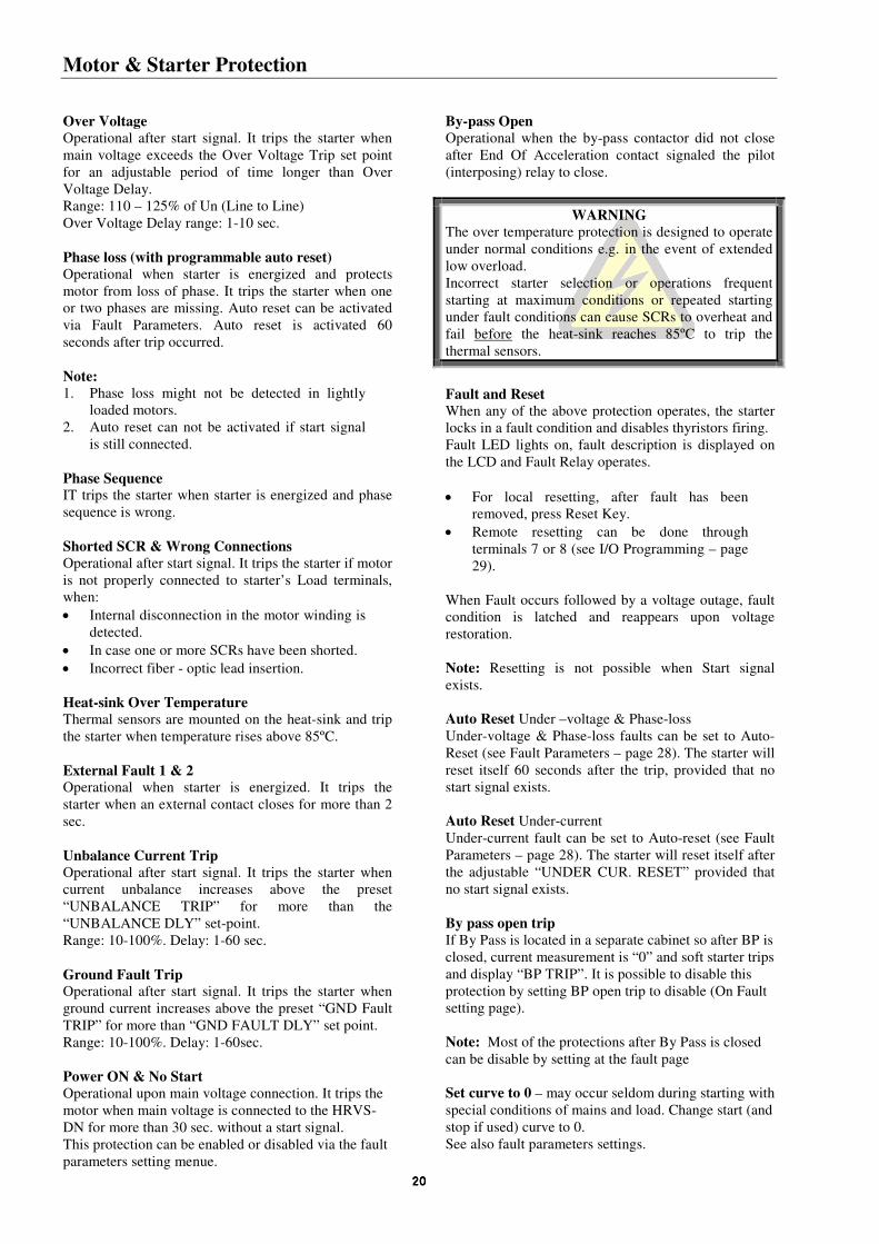
WARNING
The over temperature protection is designed to operate
under normal conditions e.g. in the event of extended
low overload.
Incorrect starter selection or operations frequent
starting at maximum conditions or repeated starting under fault conditions can cause SCRs to overheat and
fail before the heat-sink reaches 85ºC to trip the
thermal sensors.
Fault and Reset When any of the above protection operates, the starter locks in a fault condition and disables thyristors firing.
Fault LED lights on, fault description is displayed on
the LCD and Fault Relay operates.
• For local resetting, after fault has been removed, press Reset Key.
• Remote resetting can be done through
terminals 7 or 8 (see I/O Programming – page
29).
When Fault occurs followed by a voltage outage, fault condition is latched and reappears upon voltage
restoration.
Note: Resetting is not possible when Start signal
exists.
Auto Reset Under –voltage & Phase-loss
Under-voltage & Phase-loss faults can be set to Auto-
Reset (see Fault Parameters – page 28). The starter will
reset itself 60 seconds after the trip, provided that no
start signal exists.
Auto Reset Under-current
Under-current fault can be set to Auto-reset (see Fault
Parameters – page 28). The starter will reset itself after
the adjustable “UNDER CUR. RESET” provided that
no start signal exists.
By pass open trip
If By Pass is located in a separate cabinet so after BP is
closed, current measurement is “0” and soft starter trips
and display “BP TRIP”. It is possible to disable this
protection by setting BP open trip to disable (On Fault setting page).
Note: Most of the protections after By Pass is closed
can be disable by setting at the fault page
Set curve to 0 – may occur seldom during starting with
special conditions of mains and load. Change start (and
stop if used) curve to 0.
See also fault parameters settings.

Motor & Starter Protection Occurrences Table
21212121
Active During Timing And Occurrence
Start Run Stop Soft Stop
Too many starts √
Electronic Overload √
Shear Pin (Jam) * Default setting
Starter Protection – trip function at 850% FLC in less than 1 cycle. √ √ √
Motor Protection – trip function
During Soft Start / Soft Stop – factory set at 850% FLA with adj. time delay
√ √
During Run – adjustment 100 – 850% FLA with adj. time delay √
Under current √
Unbalance Current √ √ √
Ground Fault Current √
Phase loss √ √ √
Phase sequence √ √ √
Under voltage. Time delay is override in case of “No-Volt”. √ √ √
Over voltage with adjustable time delay √ √ √
Long start time (Stall protection) √
Shorted SCR & Wrong connection (Load Loss) √ √
External fault 1 & 2 √ √ √ √
SCR protection by Metal Oxide Varistors (MOV) √ √ √ √
Starter over-temperature √ √
Starter internal test
When supply voltage is connected and LED is “On” . √ √ √ √
PWR ON & NO STRT √
By-Pass Open √
Insulation alarm √
Set curve to 0 √

Standard Wiring Diagram
22222222
Will be send upon request

Front Panel
23232323
LED Arrangement
On Lights on when Control Supply voltage is connected to
the starter.
Start Lights on during start process, indicating that motor supply voltage is ramping up.
Run
Lights on after completion of starting process to
indicate that motor is receiving full voltage.
S. Stop Lights on during soft stop process to indicate that
motor supply voltage is ramping down.
Stop Lights on when motor is stopped.
Test Lights on when in “Test Mode” operation.
D. Adj. Lights on when Dual Adjustment is in operation.
Fault Lights on upon operation of any of the built-in
protection.
Keypad Provides selection of the following modes:
When Dip Switch 1 is in “On”, gray
zone shows list of maximized
parameters).
• Display Only
• Main Parameters
• Start Parameters
• Stop Parameters
• Statistical Data
• Dual-Adjustment Parameters
• Fault Parameters
• I/O Programming Parameters
• Communication Parameters.
To select function within each mode.
To increase adjusted parameters.
Press momentarily or continuously to
select forward in statistical parameters.
To decrease adjusted parameters. Press momentarily or continuously to
select revers in statistical parameters.
To save modified parameters.
To reset the starter after fault has
been removed, canceling the displayed
fault and allows restarting. Disconnect Start signal to Enable reset.
Note: Pressing Mode or Select continuously increases
parameters changing speed.
Mode
Select
Store
Reset
Min
imiz
e
Max
imiz
e

Display Mode
24242424
LCD Arrangement Two lines of 16 characters display:
System Parameters, Starter Settings, Motor Current,
Insulation and Fault Identification.
Four selectable languages – English, French, German and Spanish (see Dip Switch setting – page 7).
Example:
CURRENT LIMIT
390%
• Upper line displays functions.
• Lower line displays setting and measured
values.
Modifying parameters 1. Press mode key several times until you reach
the required Mode page.
2. Press Select to review parameters of this mode.
3. When reaching the required parameter,
modify its values with or
keys.
4. To store the new parameters, press Select until
“Store Enable” appears and then press Store
key
Note: Pressing Mode or Select keys continuously
increase parameter change speed.
Mode pages Upon Control Supply connection, the LCD displays
motor’s operating current. When Dip Switch # 1 is set
to On (see Display Options) All Mode Pages can be
reviewed by pressing the Mode key. When Dip Switch # 1 is set to off, the following Mode pages marked **
will not appear.
MAIN &PROTECT
PARAMETERS
START PARAMETERS
STOP PARAMETERS
DUAL ADJUSTMENT
PARAMETERS
FAULT PARAMETERS
I/O PROGRAMMING
PARAMETERS
COMM. DATA
STATISTICAL DATA
In this mode, parameters are not adjustable.
I1 I2 I3
80 80 80 %
Displays operating current as a percentage of motor’s
FLA.
Note: Starter’s Default Display. A time delay is initiated after pressing Mode or Select. Following the
delay, the LCD defaults back to display “% OF
MOTOR FLA”. Five minutes after programming the
LCD it returns to the Current Display.
Press Select –When option cards are not incorporated, the LCD displays
OPTION CARD
Not Installed
When Analog card is incorporated, the LCD displays
OPTION CARD
ANALOG OUTPUT
Displays analog card preset.
When Output Relays card is incorporated, the LCD
displays
OPTION CARD OUTPUT RELAYS
This concluded the “Display Mode” Pressing Select key at this point returns to the first
display.
Obtaining “Default Parameters”
a. Press Mode and keys simultaneously and the LCD will display “Store Enable
Default Parameters.”
b. Press Store and Mode keys simultaneously.
CAUTION
Obtaining Default Parameters will erase all
previously modified settings.
HRVS-DN FLC must be set to the rated starter current as specified on the starter label.
**
**
**
**

Parameter Settings
25252525
Press Mode To advance to:
MAIN & PROTECT.
PARAMETERS
Press Select Press keys to set starter FLC. Range: 20 - 1400
STARTER FLC 150 AMP
Press Select
Press keys to set motor
FLA.
Range: 33-100% of “STARTER FLC”
MOTOR FLA
150 AMP
Press Select
Press keys to Under
Current Trip set point. Range: 0 = OFF, 20-90% of FLA
UNDERCURR. TRIP 0% OF FLA
Press Select Press keys to under Current
Trip time delay set point.
Range: 1-40 sec.
UNDERCURR. DELAY 10 SEC.
Press Select Press keys to Over Current
Shear-pin set point
Range: 100 – 850% of FLA
O/C – SHEAR PIN 850% OF FLA
Press Select Press keys to set O/C Shear-
pin time delay.
Range: 0-5 sec.
O/C DELAY 0.5 SEC.
Press Select Press keys to set Overload
Current Trip.
Range: 75-150% of FLA
OVERLOAD TRIP 115% OF FLA
Press Select Press keys to set Overload
Trip time delay at 500% of motor
FLA.
Range: 1-10 sec.
OVERLOAD DELAY
4 SEC – AT 5 FLA
Press Select Press keys to set Unbalance
Trip.
Range: 10-100% of motor FLA,
Off.
UNBALANCE TRIP
20%
Press Select Press keys to set Unbalance
Trip time delay.
Range: 1-60 sec.
UNBALANCE DELAY 5 SEC.
Press Select Press keys to set Ground
Fault Trip
Range: 10-100%, Off.
GND FAULT TRIP 20% OF FLA
Press Select Press keys to set Ground
Fault Trip Delay.
Range: 1-60 sec.
GND FAULT DELAY 5 SEC.
Press Select Press keys to set Under
Voltage Trip
Range: 50-90% of Un.
UNDERVOLT. TRIP 70% of Un
Press Select Press keys to set Under
Voltage Trip time delay.
Range: 1-10 sec.
UNDERVOLT. DELAY
5 SEC.
Press Select Press keys to set Over
Voltage Trip.
Range: 110-125% of Un (can not
be set below Under Voltage), Off.
OVERVOLT. TRIP
120% of Un
Press Select Press keys to set Over
Voltage Trip time delay.
Range: 1-10 sec.
OVERVOLT DELAY 2 SEC.
Press Select
STORE ENABLE
MAIN PARAMETERS
Press Store Key to store selected
parameters.
Note: Storing selected parameters
is possible only when stop or run
LED are on. Storing cannot be
done when start, soft stop or fault
LED is on.
When parameters have been
correctly stored the LCD displays
DATA SAVED OK
This concludes Main &
Protection Parameter settings.
Pressing Select key after “Data
Saved OK” returns to the first
display in this mode.
In case of a failure in parameter storing the LCD displays.
STORAGE ERROR
Press Select button again until
“Store Enable Main Parameters”
returns then press Store key until
“Data Saved OK” appears.

Parameter Settings
26262626
Press Mode To Advance to:
START PARAMETERS
Press Select
SOFT START CURVE 1 (STANDARD)
Then press keys to set Soft Start Curve: 0 = Basic
1 = Standard Curve
2!! = Pump Control Curve # 1
3!! = Pump Control Curve # 2
4!! = Pump Control Curve # 3
5!! = Torque Control
When setting dip switch # 2 to on for Tacho Mode
Press and curve message changes to:
START TACHO. GAIN
0 (MIN. GAIN)
Then press keys to set Tacho gain:
0 = Minimum gain tacho control.
1!! = Second level Tacho gain.
2!! = Third level Tacho gain.
3!! = Fourth level Tacho gain. 4!! = Fifth level Tacho gain.
5!! = Sixth level Tacho gain.
Note: Tacho feedback is operational in its basic
form. Additional curves except for the basic linear curve are optional. Consult factory for
correct tacho selection and mechanical
installation.
Press Select,
Press keys to set Pulse Level.
Range: 70-700% of motor FLA. If Pulse Time is
longer than 1 sec then max value of pulse level is
limited to 440x(STARTER FLC / MOTOR FLA) [%]
PULSE LEVEL 70% OF FLA
Press Select,
Press keys to set Pulse Time.
Range: 0-10 sec.
PULSE TIME 0 SEC.
Note: Pulse Start has no effect with Start Curve = 0
Press Select, Press keys to set Initial Voltage.
Range: 10-50% of Un for voltage ramp.
INITIAL VOLTAGE 30%
If you use curve 0 or 1 it is possible to increase the
current within the range 100-400% of In.
The display changes to:
INITIAL CURRENT 100% OF FLA
Press Select,
Press keys to set Current Limit
Range: 100-400% of motor FLA.
CURRENT LIMIT
400% OF FLA
Press Select Press keys to set Acceleration Time
Range: 1-30 sec.
ACC. TIME 10 SEC.
Press Select Press keys to maximum Start Time.
Range: 1-30 sec.
MAX. START TIME
30 SEC.
Press Select Press keys to set the number of starts permitted
(during START period below)
Range: 1-10, Off.
NUMBER OF STARTS 1
Press Select Press keys to set number of starts time period.
Range: 1-60 min.
STARTS PERIOD 20 MIN.
Press Select Press keys to set start inhibit period
Range: 1-60 min.
START INHIBIT 15 MIN.
Press Select Press keys to set time delay for the end of acceleration contact.
Range: 0-120 sec.
RUN CONTACT DEL. 5 SEC.
Press Select To store selected parameters, press Store key.
STORE ENABLE
START PARAMETERS
When parameters have been correctly stored the LCD
reads:
DATA SAVED OK.
This includes START PARAMETERS settings.

Parameter Settings
27272727
Press Mode To advance to
STOP PARAMATERS
Press Select Then press keys to set Soft Stop Curve 0 = Basic
1 = Standard Curve
2!! = Pump Control Curve # 1
3!! = Pump Control Curve # 2
4!! = Pump Control Curve # 3
5 = Torque Control Curve
SOFT STOP CURVE
1 (STANDARD)
When setting dip sw. # 2 to on for Tacho Mode,
Press and curve message changes to:
STOP TACHO GAIN 0 (MIN GAIN)
Then press keys to set Tacho gain: 0 = Minimum gain tacho control.
1!! = Second level tacho gain.
2!! = Third level tacho gain.
3!! = Fourth level tacho gain.
4!! = Fifth level tacho gain.
5!! = Sixth level tacho gain. Note: Tacho Feedback is operational in its basic
form. Additional curves except for the
basic linear curve are optional. Consult
factory for correct tacho selection and
mechanical installation.
Press Select Then press keys to set Deceleration Time.
Range: 0-30 sec.
DEC. TIME 0 SEC.
Press Select Then press keys to set Final Torque during
Soft Stop.
Range: 0 – 10 (0 = min., 10 = max.)
FINAL TORQUE 0 (MIN)
Press Select To store selected parameters, press Store key
STORE ENABLE
STOP PARAMETERS
When parameters have been correctly stored the
LCD displays:
DATA SAVED OK
This concludes STOP PARAMETERS setting.
Press Mode To advance to Dual Adjustments when Dip Switch # 1 is set
to ON:
DUAL ADJUSTMENT
PARAMETERS
When selecting “Generator Mode” (Dip sw # 3 is On) the
following display appears instead of the above.
D. ADJ: GENERATOR
PARAMETERS
Press Select
Then press keys to set DA Initial Voltage.
Range: 10-50% of Un with initial current 100% - 400%.
DA: INIT. VOLT. 30%
Press Select Then press keys to set DA Current Limit.
Range: 100-400% of motor FLA.
DA: CUR. LIMIT 400% OF FLA
Press Select Then press keys to set DA Acceleration Time.
Range: 1-30 sec.
DA: ACC. TIME 10 SEC.
Press Select Then press keys to set DA Deceleration Time. Range: 0-30 sec.
DA: DEC. TIME 0 SEC.
Press Select
Then press keys to set DA Motor FLA
Range: 33-100% of “STARTER FLC”
DA: MOTOR FLA 150 AMP.
Press Select To store selected parameters, press Store key
STORE ENABLE
D.ADJ. PARAMETERS
When parameters have been correctly stored the LCD
displays:
DATA SAVED OK
This concluded DUAL ADJUSTMENT PARAMETERS
setting.

Parameter Settings
28282828
Press Mode Set Dip Switch # 1 to ON to advance to:
FAULT PARAMETERS
Press Select Then press keys to set Auto.Reset for Under-Voltage and Phase loss faults. Range:
Yes/No.
UV & PL AUTO RST
NO
Press Select
Then press keys to set Under Current Auto
Reset. Range: 10-120min / Off
UNDER CUR. RESET
OFF
Press Select Then press keys to set By Pass open trip.
Range: Enable\ Disable.
BY PASS OPEN TRIP
ENABLE
Press Select Then press keys to set trip after By Pass.
Range: Enable\ Disable.
Can be used to disable most of fault protections
starting 30 seconds after by-pass is closed. Use only if another protection relay is used.
TRIP AFTER BY PASS
ENABLE
Press Select
Then press keys to set By Pass auto reset.
Range: Yes \ No.
BY PASS AUTO RESET
NO
Press Select Then press keys to enable or disable “SET CURVE 0
FLT”.
Range: Enable\ Disable.
Set to disable, only if “SET CURVE TO 0” fault occurs during starting and if curve 0 starting process is not good
enough for the application.
When set to disable verify that motor starts normally in the
selected curve.
SET CURVE 0 FLT
ENABLE
Press Select Then press keys to set Powe On and no start protection. Range: Enable\ Disable.
PWR ON & NO STRT
ENABLE
Press Select Then press keys to set Insulation alarm level.
Range: Off, 0.2 – 20Mohm
INSULATION ALARM
OFF
Press Select Then press keys to set Insulation alarm trip.
Range: Off, 0.2 – 20Mohm
INSULATION TRIP
OFF
Press Select To store selected parameters press Store key
STORE ENABLE
FAULT PARAMETERS
When parameters have been correctly stored, the LCD
displays:
DATA SAVED OK
This concludes FAULT PARAMETERS setting.

Parameter Settings
29292929
Press Mode Set Dip Switch # 1 to ON, to Advance to:
I/O PROGRAMMING
PARAMETERS
Press Select Then press keys to set Terminal # 7 function Range: Test or Reset.
PROG. INPUT # 7 RESET
Press Select Then press keys to set Terminal # 8 function
Range: Dual Adjustments, Reset
PROG. INPUT # 8 DUAL ADJUSTMENT
Press Select Then press keys to set Fault Relay function
Range: Fault, Fault – Fail Safe
FAULT RELAY TYPE
FAULT
Press Select Then press keys to set Immediate Relay function
Range: Immediate, Shear-Pin
IMM / S.PIN RELAY IMMEDIATE
Press Select Then press keys to set Imm / S. Pin Relay On
Delay.
Range: Immediate 0-60 sec. / Shear-Pin 0-5 sec.
RELAY ON DELAY 0 SEC.
Press Select Then press keys to set Imm / S. Pin Relay Off
Delay.
Range: Immediate 0-60 sec. / Shear-Pin 0-5 sec.
RELAY OFF DELAY 0 SEC.
Press Select
Then press keys to set Normal or Inverted output.
Range: Normal, Inverted
ANALOG OUTPUT NORMAL
Press Select To store selected parameters, press Store key
STORE ENABLE
I / O PROG. PARAM.
When parameters are correctly stored the LCD displays
DATA SAVED OK
This concludes I/O PARAMETER setting.
Press Mode Set Dip Switch # 1 to ON, to Advance to:
COMM. PARAMETERS
Communication is optional and operates only when
starter incorporates this feature.
Note: Hardware and software are installed in the
factory.
Note: The last command determines the function when using communication and local
commands.
Protocol is factory set to the correct one according
to installed hard
ware.
COMM. PROTOCOL MODBUS
For PROFIBUS parameters see page 30.
Press Select Then press keys to set Communication Baud Rate.
Range: 1200-9600 BPS
BAUD RATE 9600
Press Select Then press keys to set Communication Parity
Check. Range: Even / Odd
PARITY CHECK EVEN
Press Select Then press keys to set Communication Serial Link
Number
Range: 1-248 (for up to 32 starters on one twisted pair)
SERIAL LINK NO. 248 (OFF)
Note: Serial link number must be set to 248 (Off) if
communication is not in use.
To store selected parameters press Store key
STORE ENABLE
COMM. PARAMETERS
When parameters have been correctly stored the LCD
displays:
DATA SAVED OK
This concludes COMMUNICATION
PARAMETERS setting.

Parameter Settings
30303030
Press Select Then press keys to set the protocol:
COMM. PROTOCOL
PROFIBUS
For MODBUS parameters see page 29.
Press Select
Then press keys to set number of input
bytes to be scanned. Range: 2, 4, 6, …32
NO. OF IN BYTES 2
Press Select Then press keys to set number of outputs.
Range: 1,2.
Where: 1 indicates no control via profibus. (only monitoring)
2 indicates full control via profibus
NO. OF OUT BYTES 1
Press Select Then press keys to set Communication Serial Link
Number
Range: 1-127 (for up to 32 starters on one twisted pair)
SERIAL LINK NO. 127 (OFF)
Note: Serial link number must be set to 127 (Off) if
communication is not in use.
Press Select To store selected parameters press Store key
STORE ENABLE
COMM. PARAMETERS
When parameters have been correctly stored the LCD
displays:
DATA SAVED OK
This concludes COMMUNICATION
PARAMETERS setting.

Parameter Settings
31313131
Press Mode To advance to
STATISTICAL DATA
-****-
Note: It is possible to scroll with the arrow
buttons.
Press Select
LAST STRT PERIOD
NO DATA
Displays last starting time in seconds.
(Time duration until motor’s current reached
nominal)
Press Select
LAST START MAX I NO DATA
Displays the maximum current at last starts.
Press Select
TOTAL RUN TIME
0 HOURS
Displays the motor runs time in hours since
commencement or since “Statistical Data” was
last reset.
Press Select
TOTAL # OF START 0
Displays the total numbers of starts since
commissioning or since “Statistical Data” was last
reset.
Press Select
LAST TRIP NO DATA
Describes last fault.
Press Select
TRIP CURRENT 0% OF FLA
Displays the current at the last fault.
Press Select
TOTAL # OF TRIPS 0
Displays the total numbers of trips since
commencement or since “statistical Data” was
last reset.
PREVIOUS TRIP – 1
Through
PREVIOUS TRIP – 9
Press Mode to return to Display Mode
I1 I2 I3
0 0 0 %
Service Mode
Press Mode and simultaneously. The LCD
displays:
STORE ENABLE
DEFAULT PARAMET.
Press Store and Mode simultaneously to store factory
Default Parameters. All previously stored parameters will be
erased. This also returns to “Display Only” Mode.
To reset Statistical Data:
Press Select
RESET STATISTICS
Press Reset and Store simultaneously to reset all your
statistical data. This also returns automatically to Statistical
Data Mode.
Press Select to see the software program version
Displays program version
PROGRAM VERSION MVSTRT.GN – 230706
For factory calibration:
Press Select Read phase to phase main voltage in % of Un.
VOLTAGE ADJUST. XXX % of Un
Press Select Reads current. For factory calibration use only.
CURRENT ADJUST. XXX% OF FLC
Press Select Display goes back to Store Enable Default Parameters
STORE ENABLE
DEFAULT PARAMET.
To exit “Service Mode” press Mode and simultaneously.
Notes:
• Entering “Service Mode” is possible only when
Stop LED is On.
• A start signal exists from this mode while in
“Service Mode”.
Note: It is necessary to connect a motor to load terminals
otherwise “Wrong Connection” protection is activated.
Other loads such as light-bulbs, resistors etc. may also cause
“Wrong Connection” Fault.

Start-up Procedure
32323232
Start-up procedure with start-stop buttons
(Use COMMISSIONING AND
OPERATION MANUAL)
1. Connect Control Supply. On and Stop
LED will light on.
2. Review all parameters with Mode and Select keys.
Set parameters as required.
3. If necessary, return to Default
Parameters (see “Service Mode” page
31).
4. Connect main voltage to starter line
terminals.
5. Set LCD to show “MOTOR FLA” (% of
motor FLA).
6. Press Start. If motor starts to turn shortly
after start signal, proceed to paragraph 7.
If not, increase “Initial Voltage” setting
and start again.
If initial inrush current and mechanical shocks during starting are too high, decrease
“Initial Voltage” settings and proceed to
paragraph 7.
7. Motor begins to turn. If speed accelerates smoothly to nominal, proceed to Para 8.
If current during acceleration is too high,
decrease “Current Limit” setting and
proceed to Para 8. If motor speed does
not accelerate to nominal, increase
Current Limit setting.
8. Press Stop and wait until motor stops.
9. Slightly increase Initial Voltage and
Current Limit settings to allow for load
changes.
10. Press Start and see that the motor
acceleration time to full speed is as
required.
11. If acceleration time is too short, increase
“Acceleration Time” setting.
12. Check total starting time and set Max.
Start Time to approximately 5 seconds
longer than the maximum time required to complete starting process.
Examples of starting curves Light Loads-Pumps, Fans, etc. Initial Voltage (IV) – set to 30% (Factory Default)
Current Limit (CL) – set 300%
Acceleration Time (AT) – set 5 sec.
U%
100%
5 t
I%600%
100%
50%
30%
10%
400%300%
t
The voltage quickly increases to the Initial Voltage value
and then gradually ramps-up to nominal. The current
simultaneously and smoothly increases to reach Current
Limit setting or less, before smoothly decreasing to the
operating current. Motor speed will accelerate to full speed quickly and smoothly.
High Inertia Loads – Fans, Centrifuges, etc Initial Voltage – set 50%
Current limit – set 400%
Acceleration time – set 20 sec
U%
100%
20 t
I%600%
100%
50%
10%
400%
t
Voltage and current increase until current reaches “Current Limit”. The voltage is held at this value until motor is close
to nominal speed, then current will begin to decrease. The
HRVS-DN continues to ramp-up the voltage until reaching
nominal. Motor speed smoothly accelerates to full speed.
Special starting – Using Dual Adjustment Using two starting characteristics, the
starter will accelerate to DA-IV
reaching 100% current limit. After tx
(Imm. Relay delay) voltage to
terminal 8 is switched off, using the standard characteristic to complete
acceleration. Useful to prevent initial
high acceleration in applications such
as submersible pumps, drum fans
with resonating frequency, etc.
U%
100
t2
t
25
10
t1
Dual Adjust Para. Standard Para.
Initial Voltage 10% 25%
Acceleration Time Tl = 2-30 sec T2 = 2-30 sec
Current Limit 200% 300-400%
Imm.Rel. ON delay Tx = 1-60 sec. -----

Menu Description
33333333
MODE MODE MODE MODE MODE
UPON INITIATION PARAMETERS DISPLAY
PAGE 1 PAGE 2 PAGE 3 PAGE 4
I1 I2 I3 0 0 0 %
MAIN & PROTECT. PARAMETERS
START PARAMETERS STOP PARAMETERS DUAL ADJUSTMENT PARAMETERS
SELECT SELECT SELECT SELECT SELECT
PRESS KEYS TO CHANGE PARAMETER VALUE
I1 I2 I3 0 0 0 A
STARTER FLC 150 AMP
SOFT START CURVE 1 (STANDARD)
SOFT STOP CURVE 1 (STANDARD)
DA: INIT. VOLT. 30%
OPTION CARD NOT INSTALLED
MOTOR FLA 150 AMP
PULSE LEVEL 70% OF FLA
DEC. TIME 0 SEC.
DA: CUR. LIMIT 400% OF FLA
UNDERCURR. TRIP 0% OF FLA
PULSE TIME 0.0 SEC.
FINAL TORQUE 0 (MIN).
DA: ACC. TIME 10 SEC.
UNDERCURR. DELAY 10 SEC
INITIAL VOLTAGE 30%
STORE ENABLE STOP PARAMETERS
DA: DEC. TIME 0 SEC.
O/C – SHEAR PIN 850% OF FLA
***INITIAL CURRENT 100% OF FLA
DA: MOTOR FLA 150 AMP.
O/C DELAY 0.5 SEC
CURRENT LIMIT 400% OF FLA
STORE ENABLE D. ADJ/ PARAMETERS
OVERLOAD TRIP 115% OF FLA
ACC. TIME 10 SEC.
OVERLOAD DELAY 4 SEC. – AT 5 FLA
MAX START TIME 30 SEC.
UNBALANCE TRIP 20%
NUMBER OF STARTS 1
UNBALANCE DELAY 5 SEC.
STARTS PERIOD 20 MIN.
GND FAULT TRIP 20% OF FLA
START INHIBIT 15 MIN.
GND FAULT DELAY 5 SEC.
RUN CONTACT DEL. 5 SEC.
UNDERVOLT. TRIP 70% OF Un
STORE ENABLE START PARAMETERS
UNDERVOLT. DELAY 5 SEC.
OVERVOLT. TRIP 120% OF Un.
OVERVOL. DELAY 2 SEC.
STORE ENABLE MAIN & PROTECT.
*** The display will be change automatically when initial voltage will increase over 50% of Un

Menu Description
34343434
MODE MODE MODE MODE MODE
PAGE 5 PAGE 6 PAGE 7
PAGE 8 PAGE 9
FAULT PARAMETERS I/0 PROGRAMING PARAMETERS
COMM. PARAMETERS STATISTICAL DATA -
- FIRING TEST
DISCONNECT MAINS
SELECT SELECT SELECT SELECT SELECT
Not Applicable PRESS KEYS TO CHANGE PARAMETER VALUE
FOR MODBUS
Note: Program input # 7 to test than store. Connect control power to terminal 7 not 3 PHASE Time is limit to 30 sec.
UV & PL AUTO RESET NO
PROG. INPUT # 7 RESET
COMM/ PROTOCOL MODBUS
LAST STRT PERIOD X SEC.
FIRING PWR SUPPLY CHECK GREEN LED
UNDER CUR. RESET OFF
PROG. INPUT # 8 DUAL ADJUSTMENT
BAUD RATE 9600
LAST START MAX I X % OF FLA
FIRING NOW CHECK GREEN & RED LEDS
BY-PASS OPEN TRIP ENABLE
FAULT RELAY TYPE FAULT
PARITY CHECK EVEN
TOTAL RUN TIME 0 HOURS
FIRING NOW CHECK ALL LEDS OF R &S
TRIP AFTER BY-PASS ENABLE
IMM / S. PIN RELAY IMMEDIATE
SERIAL LINK NO. 248 (OFF)
TOTAL # OF START 0
FIRING NOW CHECK ALL LEDS OF S & T
BY-PASS AUTO RST NO
RELAY ON DELAY 0 SEC.
STORE ENABLE COMM. PARAMETERS
LAST TRIP NO DATA
FIRING NOW CHECK ALL LEDS OF R & T
SET CURVE 0 FLT ENABLE
RELAY OFF DELAY 0 SEC.
FOR PROFIBUS TRIP CURRENT 0% OF FLA
PWR 0N & NO STRT ENABLE
ANALOG OUTPUT NORMAL
NO. OF IN BYTES 2
TOTAL # OF TRIPS 0
INSULATION ALARM OFF
STORE ENABLE I/O PROG. PARAM.
NO. OF OUT BYTES 1
PREVIOUS TRIP-1 NO DATA
INSULATION TRIP OFF
SERIAL LINK NO. 127 (OFF)
PREVIOUS TRIP-2 NO DATA
STORE ENABLE
FAULT PARMETERS
STORE ENABLE COMM. PARAMETERS
PREVIOUS TRIP-9 NO DATA

Menu Description
35353535
+ MODE STORE ENABLE DEFAULT PARAMET.
SELECT RESET STATISTICS SELECT PROGRAM VERSION MVSTRT .DN-311298
MODE + STORE RESET + STORE
SELECT
VOLTAGE ADJUST.
1% OF Un
SAVE DEFAULT PARAMETERS & BACK TO PARAMETERS DISPLAY PAGE
SAVE STATISTICAL DATA & BACK TO PAGE 9
CURRENT ADJUST. X% OF FLC
% OF MOTOR FLA STATISICAL DATA
--
BACK TO:
STORE ENABLE
DEFAULT PARAMET.
TO EXIT DEFAULT PARAMETERS MODE PRESS MODE +

Trouble Shooting
36363636
Upon fault – motor stops. Fault LED light on and Fault Relay operates. The LCD shows TRIP and fault description.
Upon Alarm – motor continues running. Alarm Relay operates and Fault LED flashes. The LCD shows ALARM and fault description.
UNBALANCE
TRIP
Current Unbalance is the difference between maximum and minimum values of motor three line currents divided by motor maximum current or motor FLA, whichever is greater. Fault
occurs when the actual Unbalance is greater than the setpoint for more than “Unbalance
Delay”.
GND FAULT TRIP It operates when Ground Current exceeds the preset “GND FAULT TRIP” for more than
“GND FAULT DLY”.
PWR ON & NO
START
It operates upon main voltage connection and activated when main voltage is connected to
the HRVS-DN for more than 30 seconds without a start signal.
BY-PASS OPEN It operates when the by-pass contactor did not close after EOA contact of the HRVS-DN
closes. Note: This protection can be disable by setting By Pass open trip to disable when the By
Pass is connected in a separate in a separate cabinet such that the starter CT’s do not
measure motor current when the By Pass contactor is closed.
TOO MANY
STARTS
Trips the starter if number of starts during “Start Period” exceeds the preset number. You have to wait until the motor and the starter cool down according to “Start Inhibit” setting.
LONG START
TIME
Trips the starter if output voltage does not reach nominal at the preset max. start time. Check
FLA, FLC, and max. start time settings. Increase Initial Voltage, Current Limit & max. start
time or decrease acceleration Time as necessary.
O/C – SHEAR PIN Trips the starter:
1. Instantaneously when current exceeds 8.5 x Starter
FLC.
2. If current exceed 8.5 x Motor FLA during starting with
adj. delay.
3. If current exceed 100-850% during running with adj. delay.
CAUTION Do not perform any
“Megger” test when the
soft-start is connected!!!
O/C Shear-Pin has a programmable delay of 0-5 seconds where the starter detects the fault
and does not trip before time delay has elapsed (delay is overridden when current reaches
8.5 x Starter FLC). Check that motor is not installed or Jammed.
Check FLA, FLC settings.
Check motor and cable connections.
Perform a “Megger” test to verify motor and cables condition
OVERLOAD Trips the starter when current exceed the Overload Trip level and thermal register has filled up.
Check FLA, FLC and Overload settings, check the motor current, wait 15 minutes to let the
motor and the starter to cool down before restarting.
UNDER CURRENT Trips the starter when line current drops below the preset level for the preset time.
Check “Under Current Trip” and “Time Delay” settings and check line currents through L1, L2 and L3.
UNDER VOLTAGE Trips the starter when line voltage drops below the preset level for the preset time.
Check “Under Voltage Trip “ and “Time Delay” settings and check the line voltages on
L1, L2 and L3.
When voltage drops to zero, the starter trips immediately with no delay.
OVER VOLTAGE Trips the starter when line voltage increases above a preset level for a preset time.
Check “Over Voltage Trip” and “Time Delay” settings. Check line voltage on L1, L2 and L3.

Trouble Shooting
37373737
PHASE LOSS Trips the starter if 1 or 2 phases are missing. Check lines voltages and correct connection
(see page 4).
PHASE
SEQUENCE
Trips the starter if line phase sequence is wrong. Check line phase sequence. If wrong, swap
two wires on line side. If motor now rotates in the wrong direction, swap two wires on load
side.
Note: Consult factory if phase sequence has to be reversed in the field.
WRONG
CONNECTION or
SHORTED SCR
Trips the starter when one or more motor phases is not connected to starter load terminals or
in case of internal disconnection in motor winding. If required, may be eliminated by using
dip switch # 3 and wiring the soft-starter in generator mode (programming D.A. parameters
accordingly*).
S.SCR OR W.CON Trips the starter and prevents starting if any SCR is short circuited or when motor windings
are shorted or when firing is incorrect (fiber optic lead incorrectly inserted may cause this
fault).
Check with an ohmmeter between L1-U, L2-V, L3-W; resistance > 20 KΩ
Check for no voltage on terminals U, V, W (from parallel system or an independent by-
pass). SCRs may fail due to: * High short current not protected by proper fuses.
* High voltage spikes not protected by proper external Varistors.
* Frequent starting at maximum conditions or fault conditions.
OVER
TEMPERATURE
Heat-sink over-temperature trips the starter when heat-sink temperature rises above 85˚C.
Improve cooling or use a by-pass control. Check that motor starting is not too frequent.
EXTERNAL
FAULT 1&2
Trips the starter when a N.O contact between terminals 19-21 closes for over two seconds.
Check contact position and cause of closure.
WRONG
PARAMETERS
Parameters not transferred from RAM to EEPROM or vice versa. After replacing the
EPROM with a new software version or after power up, press Reset, than Mode and
simultaneously and save the default parameters by pressing Store and Mode
simultaneously. (If Fault LED is on, press Reset after storing parameters).
SET CURVE TO 0 Trip occurs if the Soft Starter start with non-adequate starting curve to the network. Change
start and stop parameter to curve 0 store the data and try again.
* NOTES: Upon any fault read carefully the COMMISSIONING AND OPERATION MANUAL
before you try to identify the cause.

Technical Specification
38383838
General Information: Supply Voltage ................................... Line to Line 2,300V, 3,300V, 4,160V, 6,000V, 6,600V, 6,900V, 11,000V,
13,800V (other voltages TBD) + 10%-15%
P.I.V ratings ........................................ For 2,300V PIV is 6,900V; For 3,300V PIV is 12,500V; For 4,160V PIV is
12,500V; For 6,600V PIV is 19,500V; For 11,000V PIV is 39,000V; For
13,800V PIV is 41,000V
Frequency............................................ 45 – 65 Hz (with frequency automatically change) Control Supply .................................... 110-230V (to be specified) +10% - 15%
110VDC
Control inputs & Outputs .................... Either same as Control Supply or by special order 24-230V AC/DC (to be
specified)
Load .................................................... Three phases, three wire, squirrel cage induction motor Synchronous motor with asynchronous starting characteristics.
Start-Stop Parameters: Starter FLC.......................................... Starter Full Load Current according to Selector Guide
Motor FLA .......................................... Motor Full Load Ampere 33-100% of starter FLC
Pump Control Curves .......................... 6 field selectable curves including torque control curve preventing over-
pressure during start and water hammer during stop.
Pulse Start Level and Duration............ Adjustable level of pulse, for an adjustable time 0-10 Sec, for starting high friction loads or holding constant current level.
Initial Voltage...................................... 10-50% Un (*5-85%), 5% - by special order
Initial Current ...................................... for current ramp
Current Limit....................................... 100-400% of Motor FLA (*100-700%)
Acceleration Time ............................... 1-30 Sec (*1-90 sec)
Deceleration Time ............................... 0-30 Sec (*1-90 sec, not in Dual Adjust) Dual Adjustments ................................ Secondary start stop characteristic for: Motor FLA, Initial Voltage, Current
Limit, Acceleration Time and Deceleration Time.
Tacho and Linear Acceleration ........... 12 field selectable curves – defining Tacho Feedback gain improving
linearity.
Motor Protection: Too many starts ................................... Maximum number of starts range Off or 1-10, during a time period 1-60 min. Starts inhibit ........................................ Time period 1-60 min, where starting is prevented, after too many starts fault.
Long start time (Stall protection) ........ Maximum allowable starting time 1-30 sec. (*1-250 Sec).
Over current (Shear-pin) ..................... Two operation functions: during starting trips the starter at 850% and during
running at 100-850% In, both within 1 Cycle.
Electronic overload (I2t). .................... Adjustable 75-150% of motor FLA, adjustable trips time at 500% In for
1-10 sec. Under current ...................................... Trips when current drops below 20-90% In with time delay of 1-40 sec.
Under voltage** .................................. Trips when main voltage drops below 50-90% of Un. Time delay 1-10 Sec
Over voltage ........................................ Trips when main voltage increases above 110-125% of Un.
Time delay of 1-10 sec.
Phase loss ............................................ Trips when one or two phases are missing. Phase sequence. ................................... Trips when phase sequence is wrong.
Wrong connection & Shorted SCR… . Prevents starting, trips if motor is not connected / incorrectly connected to the
starter or in case one or more SCRs have been shorted.
Heat-sink over temp. ........................... Trips when heat-sink temperature rises above 85˚C.
External fault 1 .................................... Trips when an external contact closes for 2 sec.
External fault 2 .................................... Trips when an external contact closes for 2 sec. Unbalance Current............................... Trips when Current Unbalance exceeds preset value for more than
“Unbalance delay”
Ground Fault Current. ......................... Trips when Ground Fault Current exceeds preset level for more than “Gnd
Fault Delay”
Power ON & No Start ......................... Trips when three phases voltage is connected to the soft-starter input and start
signal was not issued for more than 30 seconds. By-Pass Open **** ............................. Trips if the by-pass contactor and one or two if its phases did not close.
* Special settings, extended range – consult factory
** With optional Auto Reset
*** Future enhancement
**** Can be disable

Technical Specification
39393939
Control: Displays ...............................................LCD in 4 – Field selectable languages and 8 LEDs
Keypad .................................................6 keys for easy setting
Aux. Contact – Immediate ...................1 C/O, 8A, 250VAC, 2000VA
Aux. Contact – End of Acceleration ....1 C/O, 8A, 250VAC, 2000VA
Fault Contact ........................................1 C/O, 8A, 250VAC, 2000VA
Communication....................................RS 485 with MODBUS or PROFIBUS protocols
Temperatures .....................................Operating -10˚ to 50˚C
Storage -20˚ to 70˚C
Enclosure:
Degree of Protection ............................IP 00 - Chassis type IP 32 - Standard
IP 54 – Optional
Paint .....................................................RAL 7032 – standard
Other colors - optional
Normal Service Conditions:
Altitude ................................................Should not exceed 1000m.
Consult factory for equipment to be used at higher altitudes. Humidity ..............................................95% Non condensed
Starter Consumption Ratings (for chassis type)
Peak consumption ................................350VA during start process and less than 20 VA otherwise