medium voltage switchgear - energy · pdf files medium voltage switchgear type simosec up to...
TRANSCRIPT

s
Medium Voltage SwitchgearType SIMOSEC up to 27.6 kV, Metal-Enclosed, Extendable, 1200 A
Medium Voltage Switchgear
OPERATING INSTRUCTIONSInstallationOperation
Order no.: SGIM-4018 (SWF 832-6059.0)
2 OPERATING INSTRUCTIONS SIMOSEC * SGIM-4018
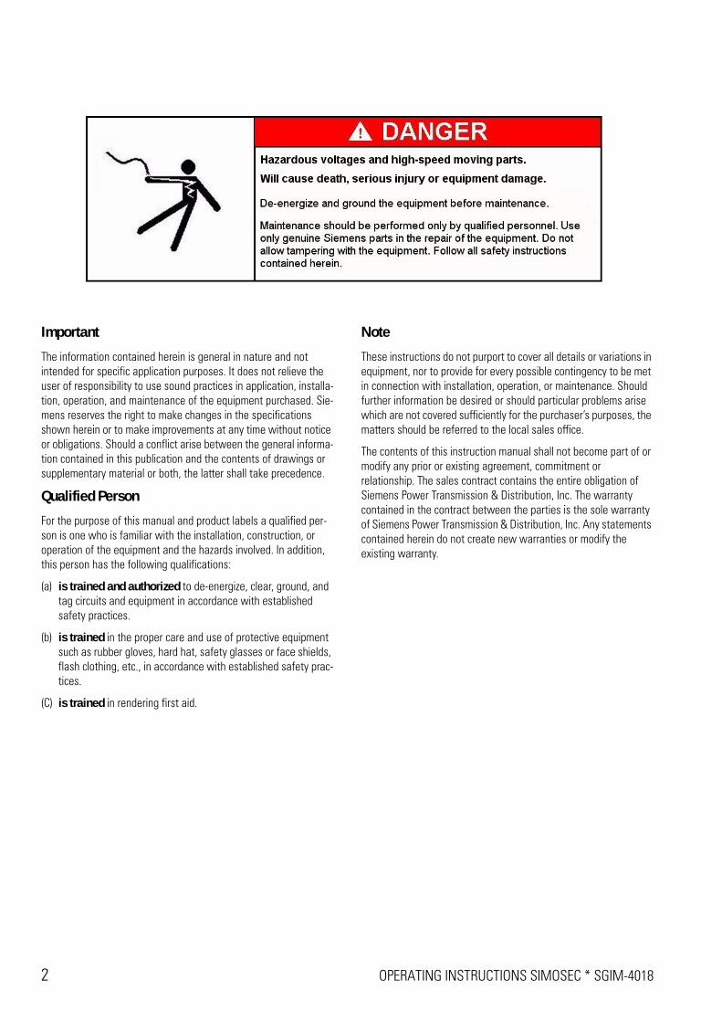
Important
The information contained herein is general in nature and not intended for specific application purposes. It does not relieve the user of responsibility to use sound practices in application, installa-tion, operation, and maintenance of the equipment purchased. Sie-mens reserves the right to make changes in the specifications shown herein or to make improvements at any time without notice or obligations. Should a conflict arise between the general informa-tion contained in this publication and the contents of drawings or supplementary material or both, the latter shall take precedence.
Qualified Person
For the purpose of this manual and product labels a qualified per-son is one who is familiar with the installation, construction, or operation of the equipment and the hazards involved. In addition, this person has the following qualifications:
(a) is trained and authorized to de-energize, clear, ground, and tag circuits and equipment in accordance with established safety practices.
(b) is trained in the proper care and use of protective equipment such as rubber gloves, hard hat, safety glasses or face shields, flash clothing, etc., in accordance with established safety prac-tices.
(C) is trained in rendering first aid.
Note
These instructions do not purport to cover all details or variations in equipment, nor to provide for every possible contingency to be met in connection with installation, operation, or maintenance. Should further information be desired or should particular problems arise which are not covered sufficiently for the purchaser’s purposes, the matters should be referred to the local sales office.
The contents of this instruction manual shall not become part of or modify any prior or existing agreement, commitment or relationship. The sales contract contains the entire obligation of Siemens Power Transmission & Distribution, Inc. The warranty contained in the contract between the parties is the sole warranty of Siemens Power Transmission & Distribution, Inc. Any statements contained herein do not create new warranties or modify the existing warranty.
SGIM-4018 * OPERATING INSTRUCTIONS SIMOSEC 3
Safety instructions .....................................4
1 Introduction.......................................................4
2 Qualified Person................................................4
3 Signal Words.....................................................4
4 Dangerous Procedures .....................................5
5 Field Service Operation.....................................5
Installation...................................................6
6 Receiving, Handling & Storage .........................6
7 Unloading the switchgear and transporting to the place of installation ...................................10
8 Installing the panels ........................................138.1 Installing the end wall .....................................138.2 Aligning the panel and fastening to the
foundation .......................................................148.3 Aligning and joining another panel ..................158.4 Installing the bus bar.......................................178.5 Installing the ground bus bar...........................208.6 Installing the end wall .....................................218.7 Connecting the station ground grid to the
switchgear frame ............................................21
9 Connecting high voltage cables ......................229.1 Preparing connection of high voltage cables ..229.2 Cable connection types...................................239.3 Mounting cold shrink at cable connections.....259.4 Connecting cable panel to high voltage ..........299.5 Connecting fuse switch panel to high voltage 309.6 Connecting metering panel to high voltage ....31
10 Installing and connecting low voltageequipment.......................................................32
10.1 Installing secondary cables .............................3210.2 Connecting low voltage wiring........................3210.3 Connecting the space heater ..........................32
11 Switchgear extension .....................................33
12 Placing SIMOSEC switchgear into service......3312.1 Safety instructions ..........................................3312.2 Instructing the operating personnel ................3312.3 Checking the assembly work and the
accessories .....................................................3312.4 Final work .......................................................3412.5 Testing the switchgear electrically..................3412.6 Operating the switchgear for test...................3512.7 Testing ............................................................3612.8 Connecting operating voltage (high voltage) ...37
Operation...................................................38
13 Indicators and control elements......................38
14 To be observed for operation..........................3914.1 Verification of readiness for service ................3914.2 Verification of safe isolation from supply of a
feeder..............................................................39
15 Operating the three-position switch................4115.1 Indicators and control elements of the three-
position switch................................................4115.2 Preconditions for operation.............................4315.3 Switching the three-position switch to
CLOSED position ............................................4315.4 Switching the three-position switch to
OPEN position.................................................4415.5 Switching the three-position switch to
GROUNDED position ......................................4515.6 Switching the three-position switch from
GROUNDED to OPEN position .......................4715.7 Switching the three-position switch with
FII-Protection-System (option).........................48
16 Operating the make-proof grounding switch ..5016.1 Indicators and control elements of the make-
proof grounding switch ...................................5016.2 Preconditions for operation.............................5116.3 Switching the make-proof grounding switch to
GROUNDED position ......................................5216.4 Switching the make-proof grounding switch to
OPEN position.................................................53
17 Grounding of panels that do not haveswitching devices ...........................................54
18 Index ...............................................................55
Safety instructions
4 SAFETY INSTRUCTIONS * SGIM-4018
Safety instructions
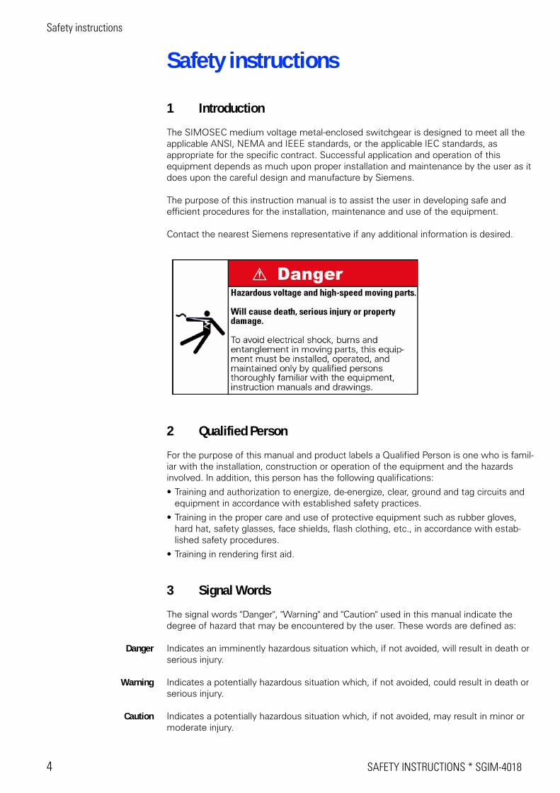
1 Introduction
The SIMOSEC medium voltage metal-enclosed switchgear is designed to meet all the applicable ANSI, NEMA and IEEE standards, or the applicable IEC standards, as appropriate for the specific contract. Successful application and operation of this equipment depends as much upon proper installation and maintenance by the user as it does upon the careful design and manufacture by Siemens.
The purpose of this instruction manual is to assist the user in developing safe and efficient procedures for the installation, maintenance and use of the equipment.
Contact the nearest Siemens representative if any additional information is desired.
2 Qualified Person
For the purpose of this manual and product labels a Qualified Person is one who is famil-iar with the installation, construction or operation of the equipment and the hazards involved. In addition, this person has the following qualifications:
• Training and authorization to energize, de-energize, clear, ground and tag circuits and equipment in accordance with established safety practices.
• Training in the proper care and use of protective equipment such as rubber gloves, hard hat, safety glasses, face shields, flash clothing, etc., in accordance with estab-lished safety procedures.
• Training in rendering first aid.
3 Signal Words
The signal words "Danger", "Warning" and "Caution" used in this manual indicate the degree of hazard that may be encountered by the user. These words are defined as:
Danger Indicates an imminently hazardous situation which, if not avoided, will result in death or serious injury.
Warning Indicates a potentially hazardous situation which, if not avoided, could result in death or serious injury.
Caution Indicates a potentially hazardous situation which, if not avoided, may result in minor or moderate injury.
SGIM-4018 * SAFETY INSTRUCTIONS 5
Safety instructions
4 Dangerous Procedures
In addition to other procedures described in this manual as dangerous, user personnel must adhere to the following:
1. Always work only on de-energized equipment. Always de-energize and ground the equipment before performing any tests, maintenance, or repair.
2. Always perform maintenance on the switching device after the spring-charged mechanisms are discharged.
3. Always let an interlock device or safety mechanism perform its function without forcing or defeating the device.
5 Field Service Operation
Siemens can provide competent, well-trained Field Service Representatives to provide technical guidance and advisory assistance for the installation, overhaul, repair and maintenance of Siemens equipment, processes and systems. Contact regional service centers, sales offices or the factory for details, or telephone Siemens Field Service at 1-800-347-6659 (919-365-2200 outside the U.S.).
Installation
6 INSTALLATION SIMOSEC * SGIM-4018
Installation
6 Receiving, Handling & Storage
The installation of the switchgear should be carefully planned before the equipment arrives at the site. This can avoid delays or equipment damage resulting from inadequate facilities or handling.
Receiving
Each transport unit of type SIMOSEC metal-enclosed switchgear is securely blocked and braced for shipment. It is crated, boxed, or covered as required by shipping conditions. Whatever method of shipment, every precaution is taken to insure its safe arrival. lf special handling is required, it is so indicated.
Handle the switchgear assembly carefully when unloading because relatively delicate instruments are included.
Identification
When the shipment includes more than one shipping group or equipment for more than one substation, marking tags are attached to each crate or package for identification. The drawing number on the tag is also on the shipping list. The shipping list identifies the contents with the section numbers included in the shipping group.
Refer to the general arrangement drawing for the location of each section within the group lineup.
Use this information to simplify the assembly operation and save unnecessary handling.
Inspection & Unpacking
Inspect the equipment as soon as possible after receiving for any damage that may have occurred in transit.
Examine before unpacking the package itself, as a damaged package may indicate an area of damage within.
Be careful when unpacking equipment.
Do not damage the plastic film protection during unloading.
Check the ready-for-service indicator for SF6 -gas
Do not climb onto the roof of the sections.
Do not use sledge hammers and crowbars. They may damage the finish, if not the equipment itself.
Use nail pullers.
Examine the equipment after unpacking for any possible damage.
Check the shipping manifest to be certain that all items have been received.
Make certain that any shortage is noted on the freight bill and contact the carrier immediately.
Notify the Siemens sales office of any shortage or damage.
SGIM-4018 * INSTALLATION SIMOSEC 7
Installation
Shipping Damage Claims
Important: The way visible shipping damage is treated by consignee prior to signing the delivery receipt can determine the outcome of the damage claim to be filed.
Notification to carrier within the 15 day limit on concealed damage is essential if loss resulting from unsettled claims is to be eliminated or minimized.
Arrival of Shipment Note whether equipment is properly protected from the elements.
Note trailer number on which the equipment arrived.
Note blocking of equipment.
Ensure count agrees with delivery receipt during unloading.
Prior to unloading when possible:
Make immediate inspection for visible damage upon arrival, and prior to disturbing or removing packaging or protective wrapping.
Document transportation damage photographically.
When total inspection cannot be made on vehicles prior to unloading:
Perform close inspection during unloading.
Note visible damage on the delivery receipt.
Document transportation damage photographically.
Damage Note any visible damage on the delivery receipt and have them acknowledged with the driver's signature.
Detail the damage as much as possible.
Document transportation damage photographically.
Include a notation "Possible internal damage, subject to inspection" on delivery receipt.
Do not let the shipment be signed for by the consignee or his agent, if the driver will not sign the delivery receipt with damage noted.
Notify the Siemens sales office immediately of any damage.
Arrange for a carrier inspection of damage immediately.
Be sure equipment is properly protected from any further damage by covering it properly after unloading.
Important: The following steps should be performed to eliminate loss due to claims by carrier that equipment was damaged or further damaged on site after unloading:
Do not move equipment from the place it was set when unloading.
Do not remove or disturb packaging or protective wrapping prior to carrier damage inspection.
Have the equipment inspected by carrier prior to handling after receipt.
Installation
8 INSTALLATION SIMOSEC * SGIM-4018
Inspection Make further inspection, if practical, for possible concealed damage while the carrier's inspector is on site.
Do the inspection for concealed damage within 15 days of receipt of equipment if it is not practical at the time the carrier's inspector is present.
Notify the carrier again and make inspection if concealed damage is found, prior to taking any corrective action to repair.
Notify Siemens sales office immediately.
Documentation & Repair The carrier inspection report and/or driver's signature on the delivery receipt does not constitute approval to repair.
Obtain the original of the carrier inspection report and forward it along with a copy of the noted delivery receipt to the Siemens sales office.
Siemens must have approval from the carrier before any repair work can be performed.
The documents must be provided to Siemens before approval can be obtained,
Note: Any determination as to whether the equipment was properly loaded or properly prepared by shipper for over- the-road travel cannot be made at the destination. Shipments are not released from the factory without a clear bill of lading. Approved methods are employed for preparation, loading, blocking and tarping of the equipment before it leaves the Siemens factory. Therefore, if the equipment is received in a damaged condition, this damage to the equipment had to occur while enroute due to conditions beyond Siemens control. lf the procedure outlined above is not followed by the consignee, purchaser, or his agent, Siemens cannot be held liable for repairs. Siemens will not be held liable for repairs in any case where the work was performed prior to authorization from Siemens.
SGIM-4018 * INSTALLATION SIMOSEC 9
Installation
Switchgear room
Please observe the following points when selecting and preparing the switchgear room:
• Space to move switchgear into the room
• Room size
• Door dimensions
• Construction and load-bearing capacity of the floor
• Illumination, heating and power supply
• Installation of foundation rails
• Installation of high voltage cables
• Grounding system
Tools / Auxiliary means
Before starting to work on the switchgear, provide the tools / auxiliary means required:
• Angular hex key 10 mm (Allen screwdriver)
• Torx screwdriver T30 M6
• Torque wrench 15 - 27 lbf-ft (20 - 36 Nm)
• Ratchet, 1/4’’ drive
• Extension 1/4’’ drive, length 6’’ (150 mm)
• Sockets, metric, 1/4’’ drive (10 mm, 13 mm, 16 mm, 18 mm)
• Laser level
• Shim plates for adapting for floor unevenness 0.02 - 0.04 in. (0.5 - 1.0 mm)or as needed
• Household cleaner, Isopropyl alcohol
• Suitable movable lifting device
• Roller crowbars
• Transport rollers
Installation
10 INSTALLATION SIMOSEC * SGIM-4018
7 Unloading the switchgear and transporting to the place of installation
Transport unit and packing
Transport unit Transport units consist either of:
• individual switchpanels – one panel per pallet (for interconnection at site) – several panels per pallet (for interconnection at site)
• or pre-assembled panel groups up to a maximum of 3 panels, with interconnection bus bars installed (optional)
• and accessories.
Packing The transport units can be packed as follows:
• on pallets, covered with plastic film
• in a seaworthy crate (switchgear is sealed with desiccant bags in plastic film)
• other packings in special cases (e.g. cardboard box for air-freight).
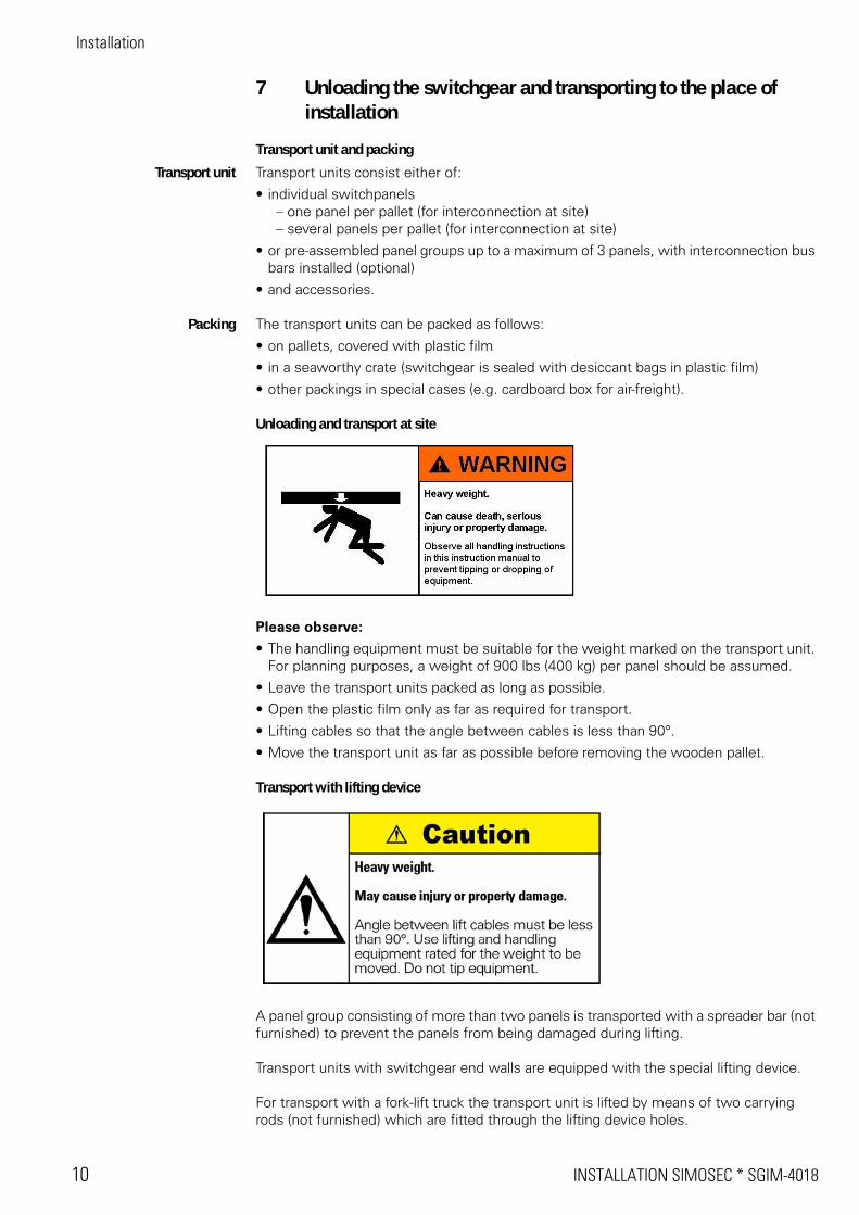
Unloading and transport at site
Please observe:
• The handling equipment must be suitable for the weight marked on the transport unit. For planning purposes, a weight of 900 lbs (400 kg) per panel should be assumed.
• Leave the transport units packed as long as possible.
• Open the plastic film only as far as required for transport.
• Lifting cables so that the angle between cables is less than 90°.
• Move the transport unit as far as possible before removing the wooden pallet.
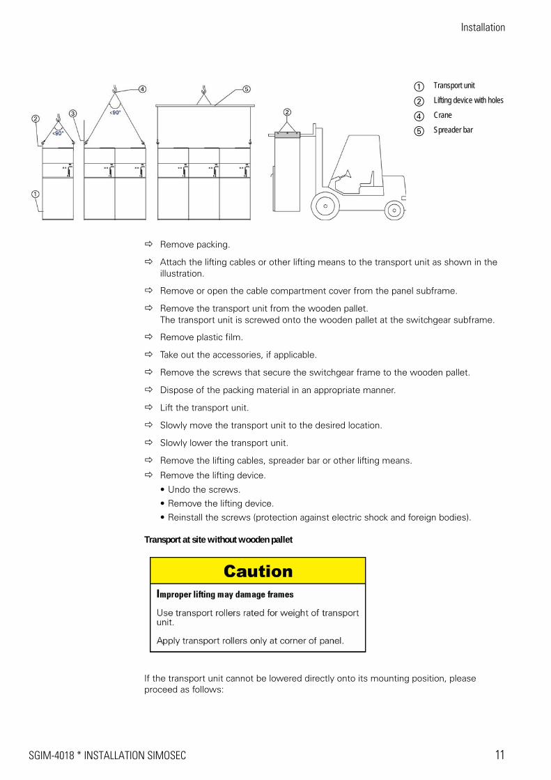
Transport with lifting device
A panel group consisting of more than two panels is transported with a spreader bar (not furnished) to prevent the panels from being damaged during lifting.
Transport units with switchgear end walls are equipped with the special lifting device.
For transport with a fork-lift truck the transport unit is lifted by means of two carrying rods (not furnished) which are fitted through the lifting device holes.
SGIM-4018 * INSTALLATION SIMOSEC 11
Installation
Remove packing.
Attach the lifting cables or other lifting means to the transport unit as shown in the illustration.
Remove or open the cable compartment cover from the panel subframe.
Remove the transport unit from the wooden pallet.The transport unit is screwed onto the wooden pallet at the switchgear subframe.
Remove plastic film.
Take out the accessories, if applicable.
Remove the screws that secure the switchgear frame to the wooden pallet.
Dispose of the packing material in an appropriate manner.
Lift the transport unit.
Slowly move the transport unit to the desired location.
Slowly lower the transport unit.
Remove the lifting cables, spreader bar or other lifting means.
Remove the lifting device.
• Undo the screws.
• Remove the lifting device.
• Reinstall the screws (protection against electric shock and foreign bodies).
Transport at site without wooden pallet
If the transport unit cannot be lowered directly onto its mounting position, please proceed as follows:
a Transport unit
s Lifting device with holes
f Crane
g Spreader bar
Installation
12 INSTALLATION SIMOSEC * SGIM-4018
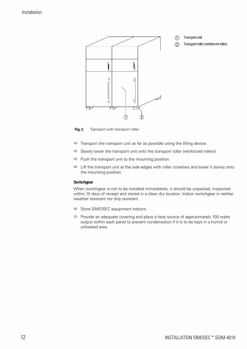
Transport the transport unit as far as possible using the lifting device.
Slowly lower the transport unit onto the transport roller (reinforced rollers).
Push the transport unit to the mounting position.
Lift the transport unit at the side edges with roller crowbars and lower it slowly onto the mounting position.
Switchgear
When switchgear is not to be installed immediately, it should be unpacked, inspected within 15 days of receipt and stored in a clean dry location. Indoor switchgear is neither weather resistant nor drip resistant.
Store SIMOSEC equipment indoors.
Provide an adequate covering and place a heat source of approximately 100 watts output within each panel to prevent condensation if it is to be kept in a humid or unheated area.
Fig. 1: Transport with transport roller
a Transport unit
s Transport roller (reinforced roller)
SGIM-4018 * INSTALLATION SIMOSEC 13
Installation
8 Installing the panels
If required, the actions described in this section must be repeated until all panels are bolted together.
In the operations described in the following sections, it is assumed that
• the transport units are installed starting either from the left or right.
• a new switchgear is being installed which has not been connected to the mains yet, and that it is therefore not energized.
8.1 Installing the end wall
There must not be any partition wall between the end wall and the frame of the end panel. Partition walls are only used to separate individual panels, respectively the cable compartments ( see figure 6: Bolted joint of panels ). The end panels are shipped from the factory without partition wall, except for group orders without a specified panel configuration. In this case, remove the partition wall before starting installation.
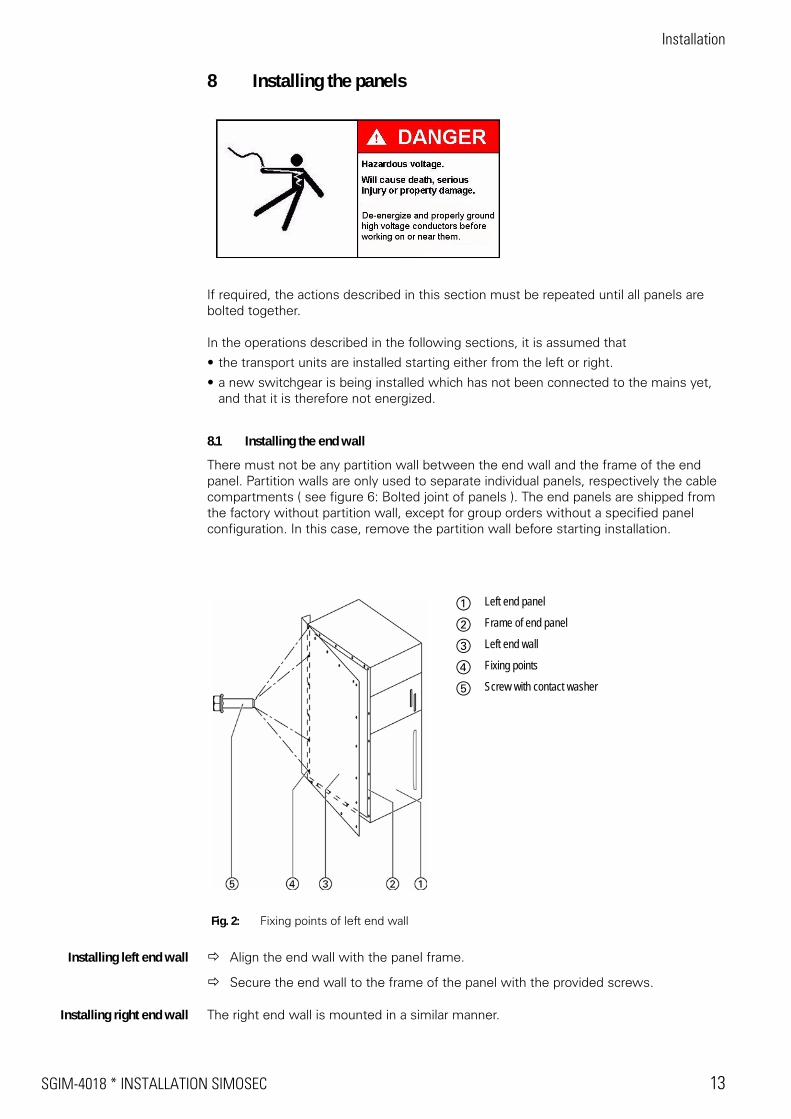
Installing left end wall Align the end wall with the panel frame.
Secure the end wall to the frame of the panel with the provided screws.
Installing right end wall The right end wall is mounted in a similar manner.
Fig. 2: Fixing points of left end wall
a Left end panel
s Frame of end panel
d Left end wall
f Fixing points
g Screw with contact washer
Installation
14 INSTALLATION SIMOSEC * SGIM-4018
8.2 Aligning the panel and fastening to the foundation
Aligning the panel Observe the minimum distances to the side and rear wall of the switchgear room in accordance with the switchgear arrangement drawing. For the dimensions and minimum distances of the panels, please refer to the dimension drawing and arrangement diagram for the switchgear.
The switchgear may have a level difference of 0.04 in./yd (1 mm/m) as a maximum.
Align the panel in horizontal position.
Align the panel in vertical position.
Check to assure that the panel is aligned (levelled to a maximum level difference of 0.04 in./yd (1 mm/m).
Fastening the panel to thefoundation
Fasten the panel to the foundation at 4 points at least.
There are two possibilities for fastening the panel to the foundation :
• bolting to sill channels (not furnished)
• bolting to foundation inserts (not furnished)
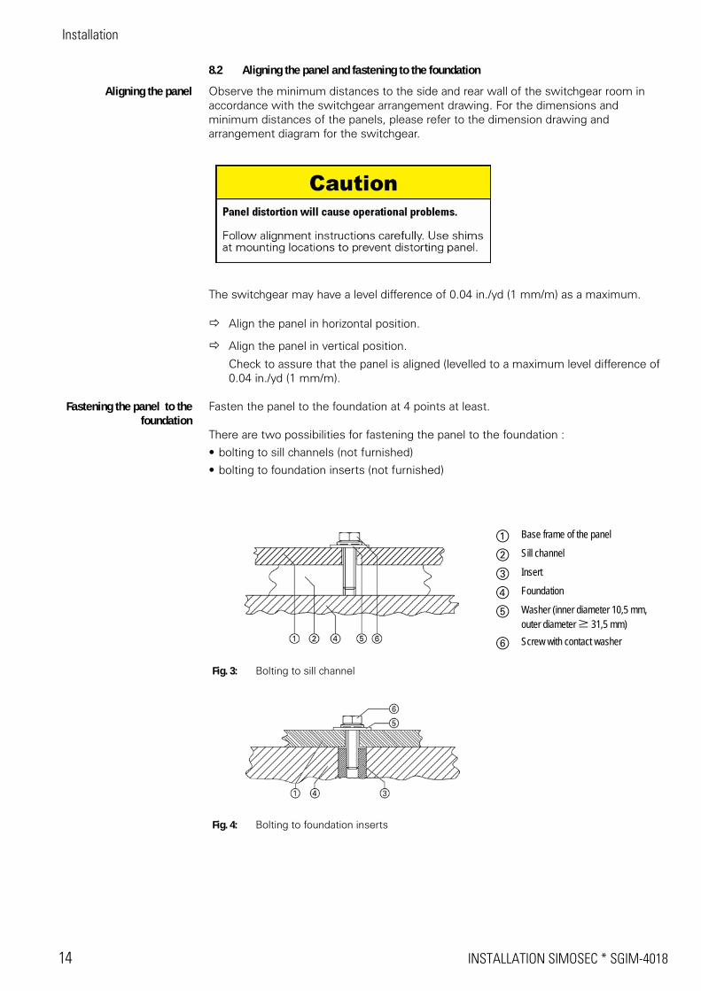
Fig. 3: Bolting to sill channel
a Base frame of the panel
s Sill channel
d Insert
f Foundation
g Washer (inner diameter 10,5 mm, outer diameter W 31,5 mm)
h Screw with contact washer
Fig. 4: Bolting to foundation inserts
SGIM-4018 * INSTALLATION SIMOSEC 15
Installation
Bolting the panel to thesill channels
Align the panel in horizontal and vertical position.
Bolt the panel to the sill channels, without distorting the panel.
Bolting the panel to thefoundation inserts
Drill holes for inserts according to the hole pattern (see dimension drawing).
Install the insert anchors.
Clean drilling dust and debris from the panel.
Align the panel in horizontal and vertical position.
Bolt the panel to the foundation inserts, without distorting the panel.
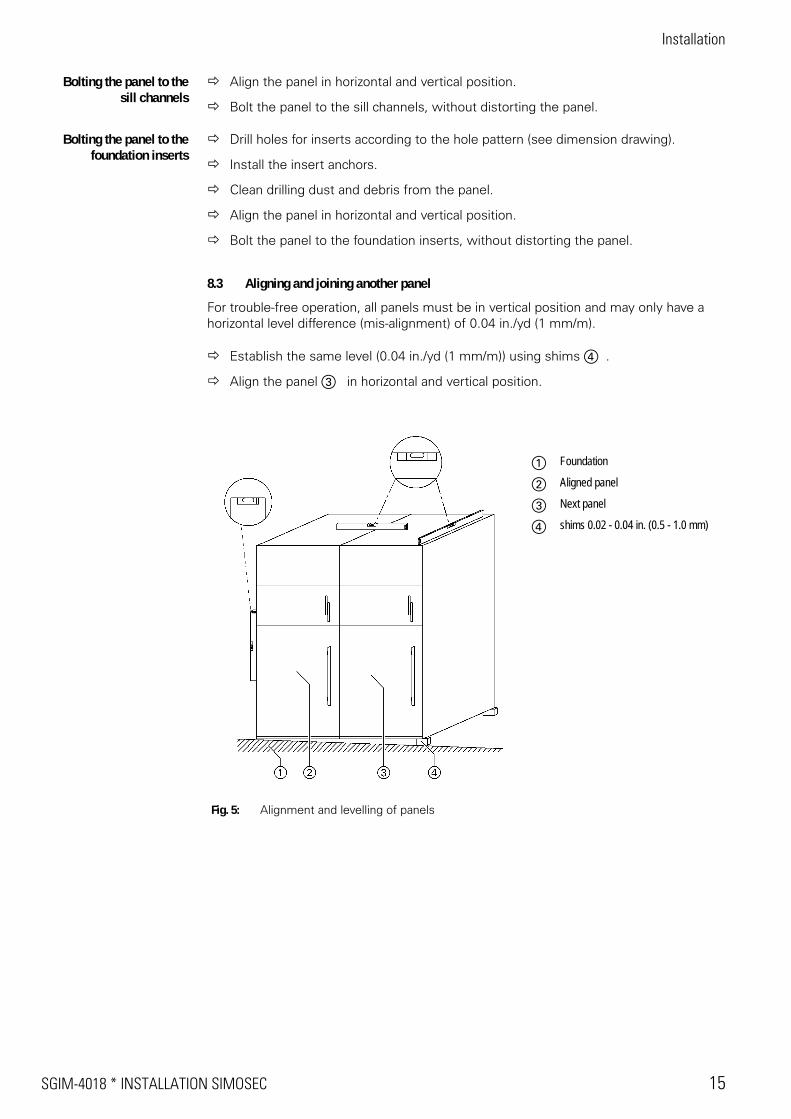
8.3 Aligning and joining another panel
For trouble-free operation, all panels must be in vertical position and may only have a horizontal level difference (mis-alignment) of 0.04 in./yd (1 mm/m).
Establish the same level (0.04 in./yd (1 mm/m)) using shims f .
Align the panel d in horizontal and vertical position.
Fig. 5: Alignment and levelling of panels
a Foundation
s Aligned panel
d Next panel
f shims 0.02 - 0.04 in. (0.5 - 1.0 mm)
Installation
16 INSTALLATION SIMOSEC * SGIM-4018
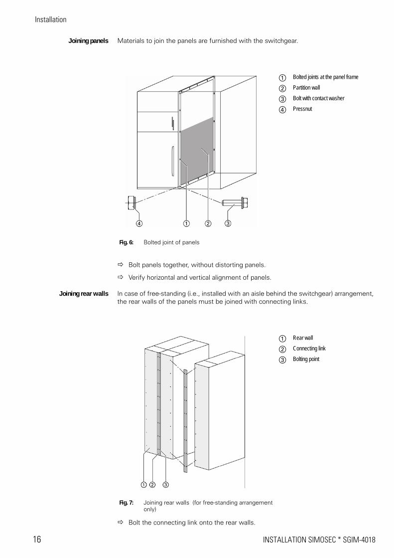
Joining panels Materials to join the panels are furnished with the switchgear.
Bolt panels together, without distorting panels.
Verify horizontal and vertical alignment of panels.
Joining rear walls In case of free-standing (i.e., installed with an aisle behind the switchgear) arrangement, the rear walls of the panels must be joined with connecting links.
Bolt the connecting link onto the rear walls.
Fig. 6: Bolted joint of panels
a Bolted joints at the panel frame
s Partition wall
d Bolt with contact washer
f Pressnut
Fig. 7: Joining rear walls (for free-standing arrangement only)
a Rear wall
s Connecting link
d Bolting point
SGIM-4018 * INSTALLATION SIMOSEC 17
Installation
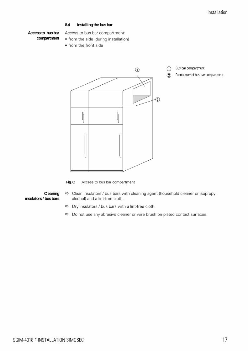
8.4 Installing the bus bar
Access to bus bar compartment
Access to bus bar compartment:
• from the side (during installation)
• from the front side
Cleaninginsulators / bus bars
Clean insulators / bus bars with cleaning agent (household cleaner or isopropyl alcohol) and a lint-free cloth.
Dry insulators / bus bars with a lint-free cloth.
Do not use any abrasive cleaner or wire brush on plated contact surfaces.
Fig. 8: Access to bus bar compartment
a Bus bar compartment
s Front cover of bus bar compartment
Installation
18 INSTALLATION SIMOSEC * SGIM-4018
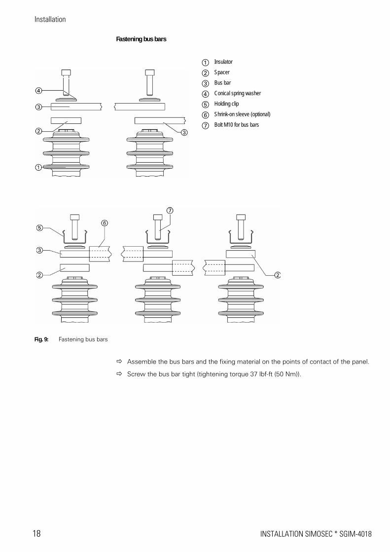
Fastening bus bars
Assemble the bus bars and the fixing material on the points of contact of the panel.
Screw the bus bar tight (tightening torque 37 lbf-ft (50 Nm)).
a Insulator
s Spacer
d Bus bar
f Conical spring washer
g Holding clip
h Shrink-on sleeve (optional)
j Bolt M10 for bus bars
Fig. 9: Fastening bus bars
SGIM-4018 * INSTALLATION SIMOSEC 19
Installation
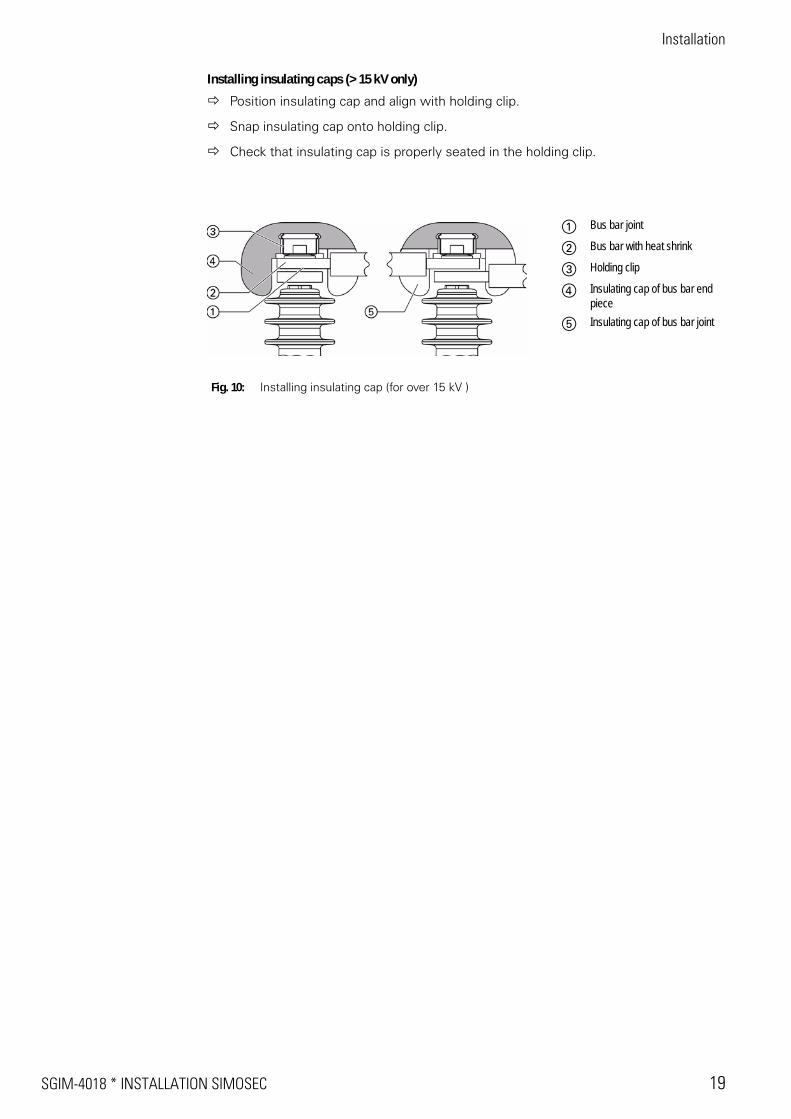
Installing insulating caps (> 15 kV only)
Position insulating cap and align with holding clip.
Snap insulating cap onto holding clip.
Check that insulating cap is properly seated in the holding clip.
Fig. 10: Installing insulating cap (for over 15 kV )
a Bus bar joint
s Bus bar with heat shrink
d Holding clip
f Insulating cap of bus bar end piece
g Insulating cap of bus bar joint
Installation
20 INSTALLATION SIMOSEC * SGIM-4018
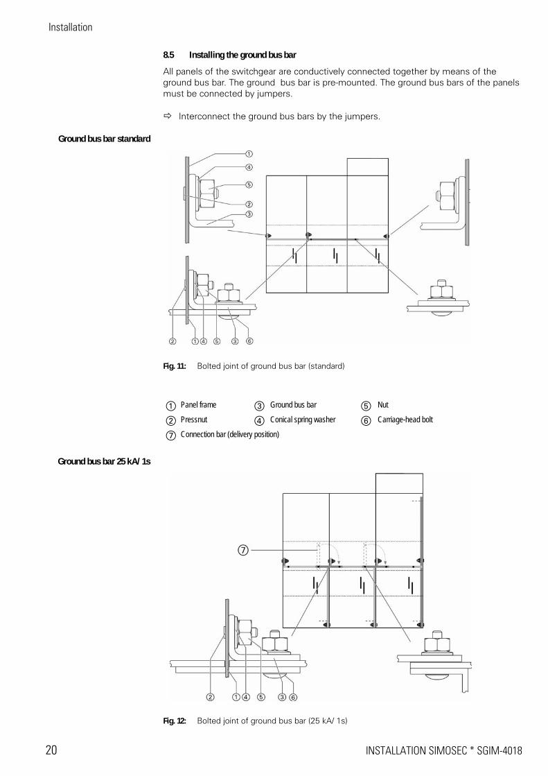
8.5 Installing the ground bus bar
All panels of the switchgear are conductively connected together by means of the ground bus bar. The ground bus bar is pre-mounted. The ground bus bars of the panels must be connected by jumpers.
Interconnect the ground bus bars by the jumpers.
Ground bus bar standard
Fig. 11: Bolted joint of ground bus bar (standard)
Ground bus bar 25 kA/ 1s
Fig. 12: Bolted joint of ground bus bar (25 kA/ 1s)
a Panel frame d Ground bus bar g Nut
s Pressnut f Conical spring washer h Carriage-head bolt
j Connection bar (delivery position)
SGIM-4018 * INSTALLATION SIMOSEC 21
Installation
8.6 Installing the end wall
The installation of the switchpanels is completed by installing the second end wall (see "Installing the panels’’, page 13).
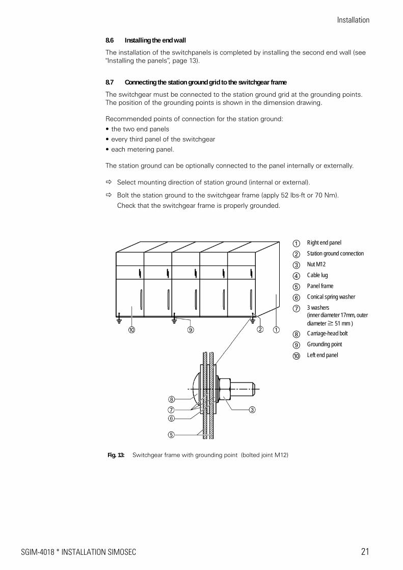
8.7 Connecting the station ground grid to the switchgear frame
The switchgear must be connected to the station ground grid at the grounding points. The position of the grounding points is shown in the dimension drawing.
Recommended points of connection for the station ground:
• the two end panels
• every third panel of the switchgear
• each metering panel.
The station ground can be optionally connected to the panel internally or externally.
Select mounting direction of station ground (internal or external).
Bolt the station ground to the switchgear frame (apply 52 lbs-ft or 70 Nm).
Check that the switchgear frame is properly grounded.
Fig. 13: Switchgear frame with grounding point (bolted joint M12)
a Right end panel
s Station ground connection
d Nut M12
f Cable lug
g Panel frame
h Conical spring washer
j 3 washers(inner diameter 17mm, outer diameter W 51 mm )
k Carriage-head bolt
l Grounding point
; Left end panel
Installation
22 INSTALLATION SIMOSEC * SGIM-4018
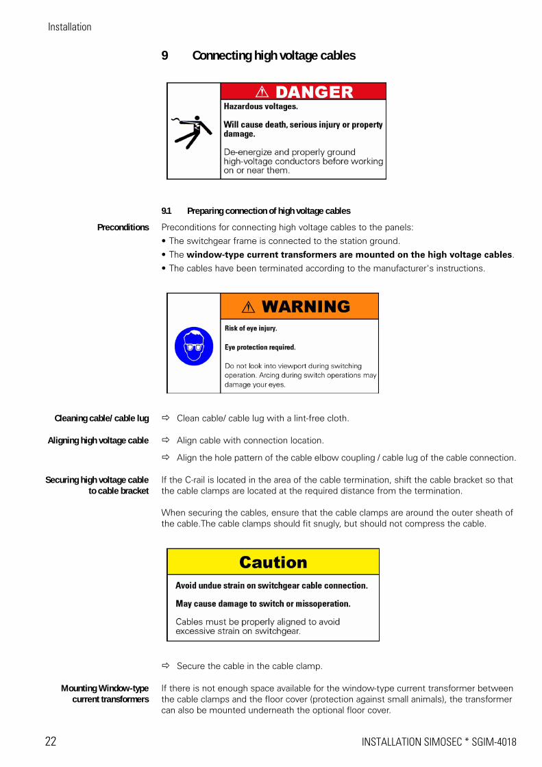
9 Connecting high voltage cables
9.1 Preparing connection of high voltage cables
Preconditions Preconditions for connecting high voltage cables to the panels:
• The switchgear frame is connected to the station ground.
• The window-type current transformers are mounted on the high voltage cables.
• The cables have been terminated according to the manufacturer's instructions.
Cleaning cable/ cable lug Clean cable/ cable lug with a lint-free cloth.
Aligning high voltage cable Align cable with connection location.
Align the hole pattern of the cable elbow coupling / cable lug of the cable connection.
Securing high voltage cableto cable bracket
If the C-rail is located in the area of the cable termination, shift the cable bracket so that the cable clamps are located at the required distance from the termination.
When securing the cables, ensure that the cable clamps are around the outer sheath of the cable.The cable clamps should fit snugly, but should not compress the cable.
Secure the cable in the cable clamp.
Mounting Window-typecurrent transformers
If there is not enough space available for the window-type current transformer between the cable clamps and the floor cover (protection against small animals), the transformer can also be mounted underneath the optional floor cover.

SGIM-4018 * INSTALLATION SIMOSEC 23
Installation
Break the recess for the retaining device out of the optional floor cover at the point provided for this purpose.
Bolt the retaining device for the window-type current transformer to the cable bracket.
Mount the window-type current transformer on the retaining device.
Install the secondary leads of the window-type current transformer through the metal duct to the associated terminal strip in the terminal connection compartment.
Connecting cable shields The cable shields of all three phases (L1, L2 and L3) are connected to one common grounding point. The cable shields have to be routed through the windows of the current transformers.
Route the cable shields directly to the C-rail, or alternatively, to the ground bus bar.Ensure a minimum clearance of 210 mm (8.27 in.) to live parts!
Bolt the cable shields to the C-rail, or alternatively, to the ground bus bar.
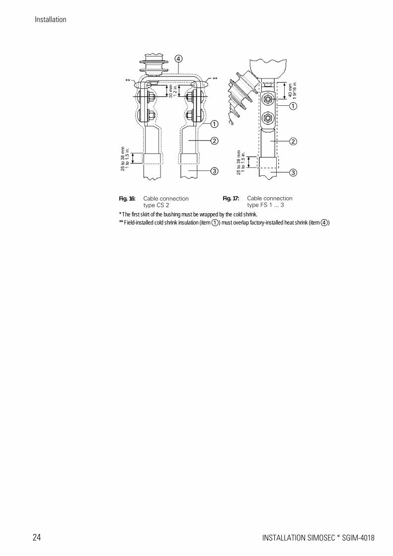
9.2 Cable connection types
Fig. 14: Cable connection type CC 1
Fig. 15: Cable connection type CS 1
a Cold shrink insulation(for over 15 kV)
s Cable lug
d Cable termination
f Heat shrink insulation(>15 kV, factory installed)
Installation
24 INSTALLATION SIMOSEC * SGIM-4018
Fig. 16: Cable connection type CS 2
Fig. 17: Cable connection type FS 1 ... 3
* The first skirt of the bushing must be wrapped by the cold shrink.** Field-installed cold shrink insulation (item a) must overlap factory-installed heat shrink (item f)
SGIM-4018 * INSTALLATION SIMOSEC 25
Installation
9.3 Mounting cold shrink at cable connections
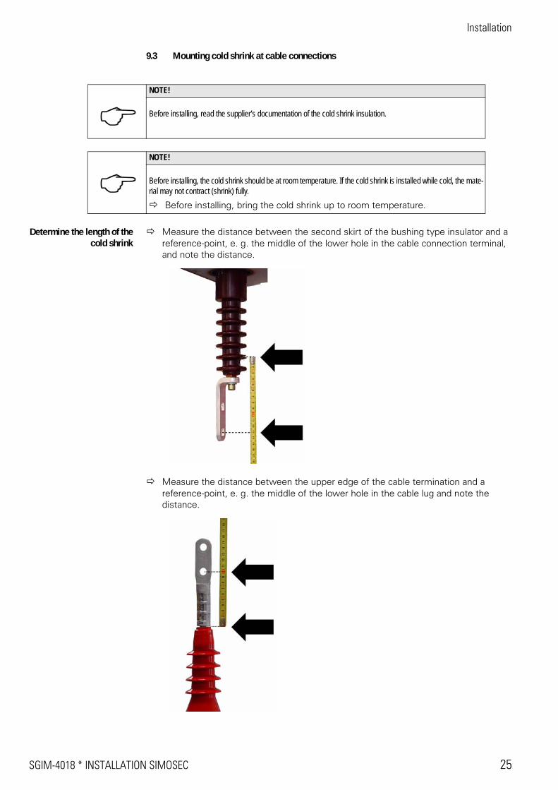
Determine the length of thecold shrink
Measure the distance between the second skirt of the bushing type insulator and a reference-point, e. g. the middle of the lower hole in the cable connection terminal, and note the distance.
Measure the distance between the upper edge of the cable termination and a reference-point, e. g. the middle of the lower hole in the cable lug and note the distance.
NOTE!
Before installing, read the supplier’s documentation of the cold shrink insulation.
NOTE!
Before installing, the cold shrink should be at room temperature. If the cold shrink is installed while cold, the mate-rial may not contract (shrink) fully.
Before installing, bring the cold shrink up to room temperature.
Installation
26 INSTALLATION SIMOSEC * SGIM-4018
Add the two distances together and add 1 inch to the sum of the distances.
r The result of this addition is the necessary length of the cold shrink. This length is approximately equal to the length „a“ (see Fig. 14: Cable connection type CC 1, page 23).
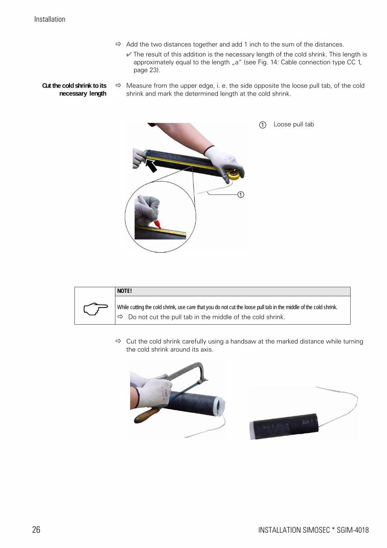
Cut the cold shrink to itsnecessary length
Measure from the upper edge, i. e. the side opposite the loose pull tab, of the cold shrink and mark the determined length at the cold shrink.
Cut the cold shrink carefully using a handsaw at the marked distance while turning the cold shrink around its axis.
a Loose pull tab
NOTE!
While cutting the cold shrink, use care that you do not cut the loose pull tab in the middle of the cold shrink.Do not cut the pull tab in the middle of the cold shrink.
SGIM-4018 * INSTALLATION SIMOSEC 27
Installation
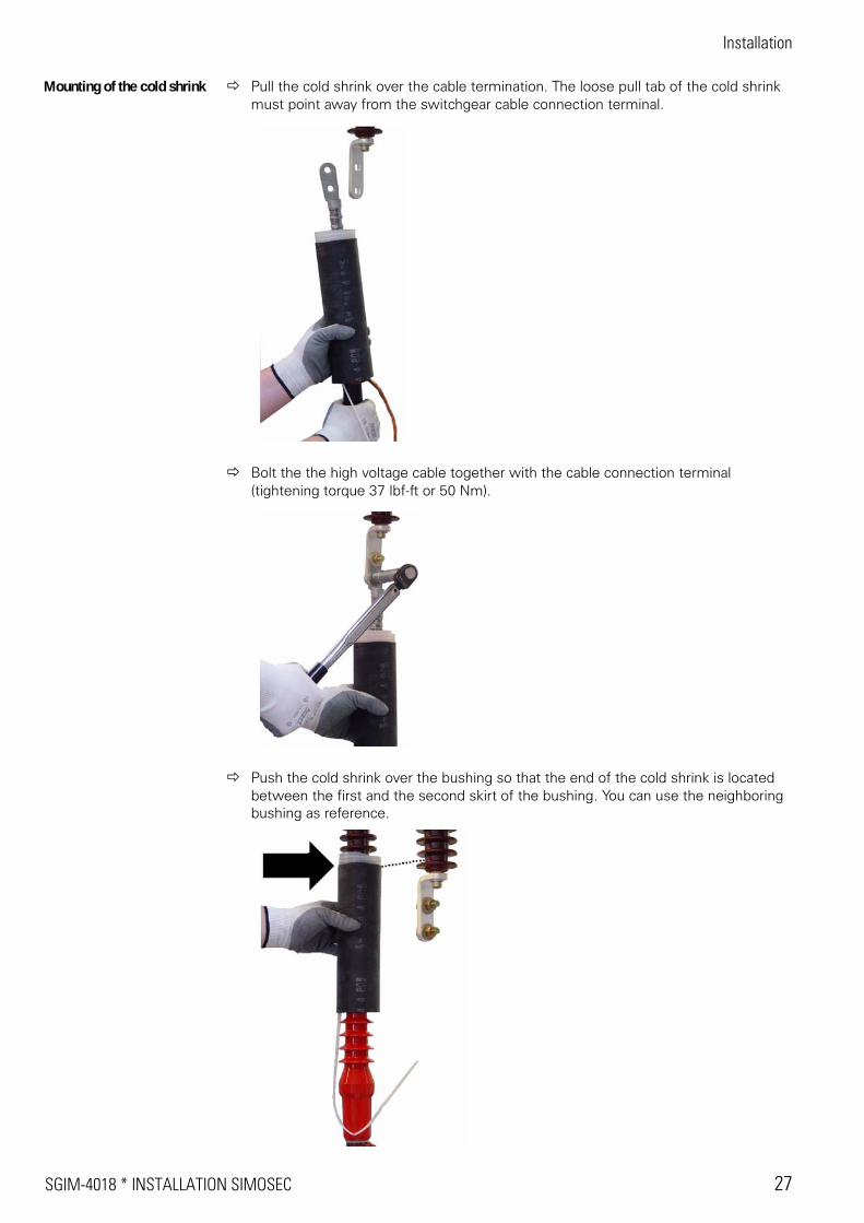
Mounting of the cold shrink Pull the cold shrink over the cable termination. The loose pull tab of the cold shrink must point away from the switchgear cable connection terminal.
Bolt the the high voltage cable together with the cable connection terminal (tightening torque 37 lbf-ft or 50 Nm).
Push the cold shrink over the bushing so that the end of the cold shrink is located between the first and the second skirt of the bushing. You can use the neighboring bushing as reference.
Installation
28 INSTALLATION SIMOSEC * SGIM-4018
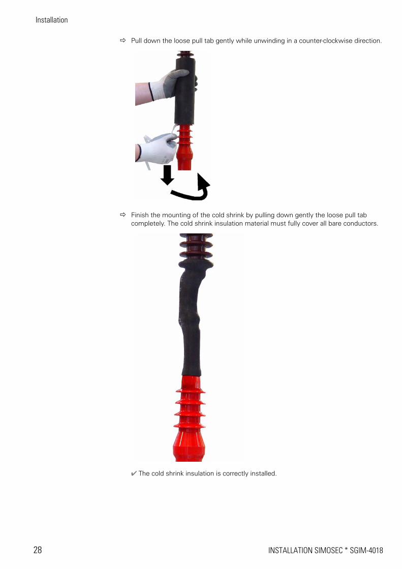
Pull down the loose pull tab gently while unwinding in a counter-clockwise direction.
Finish the mounting of the cold shrink by pulling down gently the loose pull tab completely. The cold shrink insulation material must fully cover all bare conductors.
r The cold shrink insulation is correctly installed.
SGIM-4018 * INSTALLATION SIMOSEC 29
Installation
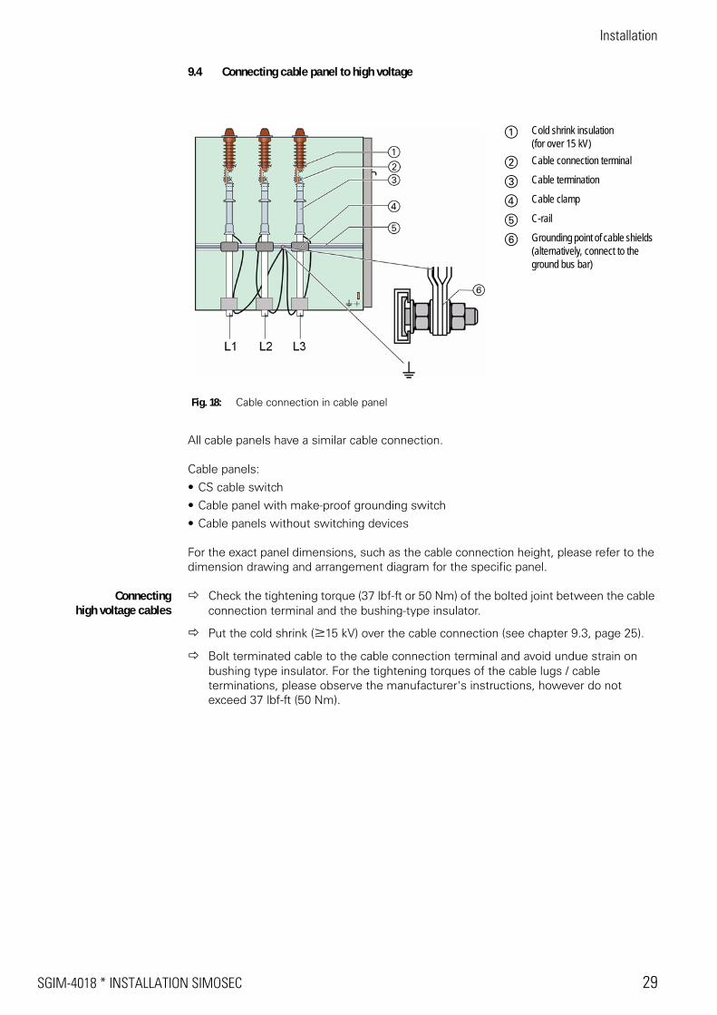
9.4 Connecting cable panel to high voltage
All cable panels have a similar cable connection.
Cable panels:
• CS cable switch
• Cable panel with make-proof grounding switch
• Cable panels without switching devices
For the exact panel dimensions, such as the cable connection height, please refer to the dimension drawing and arrangement diagram for the specific panel.
Connectinghigh voltage cables
Check the tightening torque (37 lbf-ft or 50 Nm) of the bolted joint between the cable connection terminal and the bushing-type insulator.
Put the cold shrink (W15 kV) over the cable connection (see chapter 9.3, page 25).
Bolt terminated cable to the cable connection terminal and avoid undue strain on bushing type insulator. For the tightening torques of the cable lugs / cable terminations, please observe the manufacturer's instructions, however do not exceed 37 lbf-ft (50 Nm).
Fig. 18: Cable connection in cable panel
a Cold shrink insulation(for over 15 kV)
s Cable connection terminal
d Cable termination
f Cable clamp
g C-rail
h Grounding point of cable shields (alternatively, connect to the ground bus bar)
Installation
30 INSTALLATION SIMOSEC * SGIM-4018
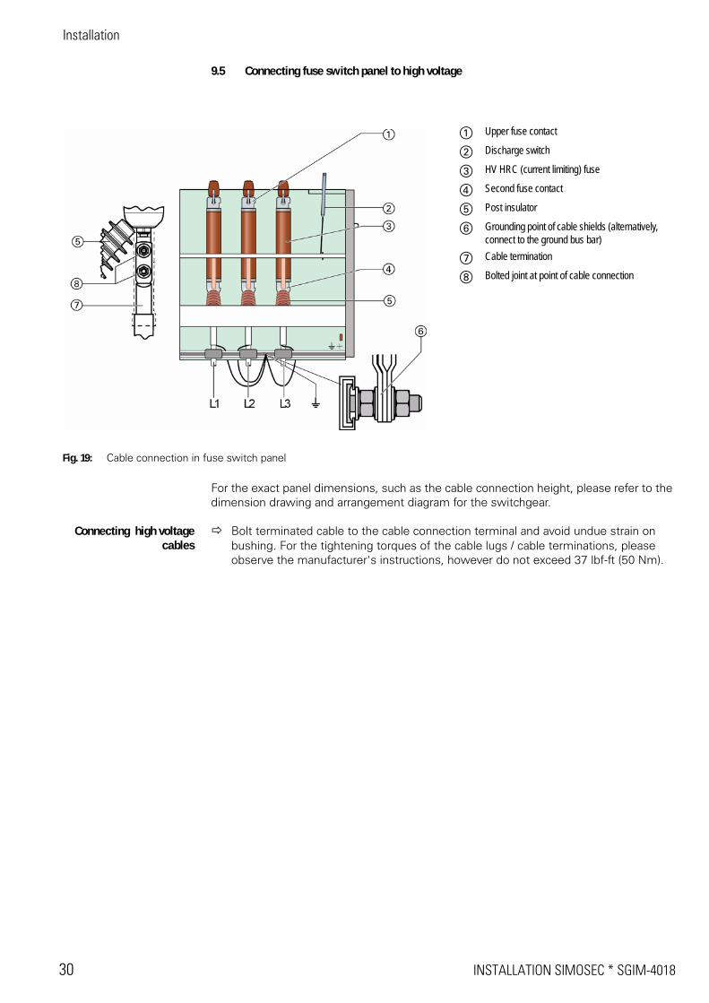
9.5 Connecting fuse switch panel to high voltage
For the exact panel dimensions, such as the cable connection height, please refer to the dimension drawing and arrangement diagram for the switchgear.
Connecting high voltagecables
Bolt terminated cable to the cable connection terminal and avoid undue strain on bushing. For the tightening torques of the cable lugs / cable terminations, please observe the manufacturer's instructions, however do not exceed 37 lbf-ft (50 Nm).
Fig. 19: Cable connection in fuse switch panel
a Upper fuse contact
s Discharge switch
d HV HRC (current limiting) fuse
f Second fuse contact
g Post insulator
h Grounding point of cable shields (alternatively, connect to the ground bus bar)
j Cable termination
k Bolted joint at point of cable connection
SGIM-4018 * INSTALLATION SIMOSEC 31
Installation
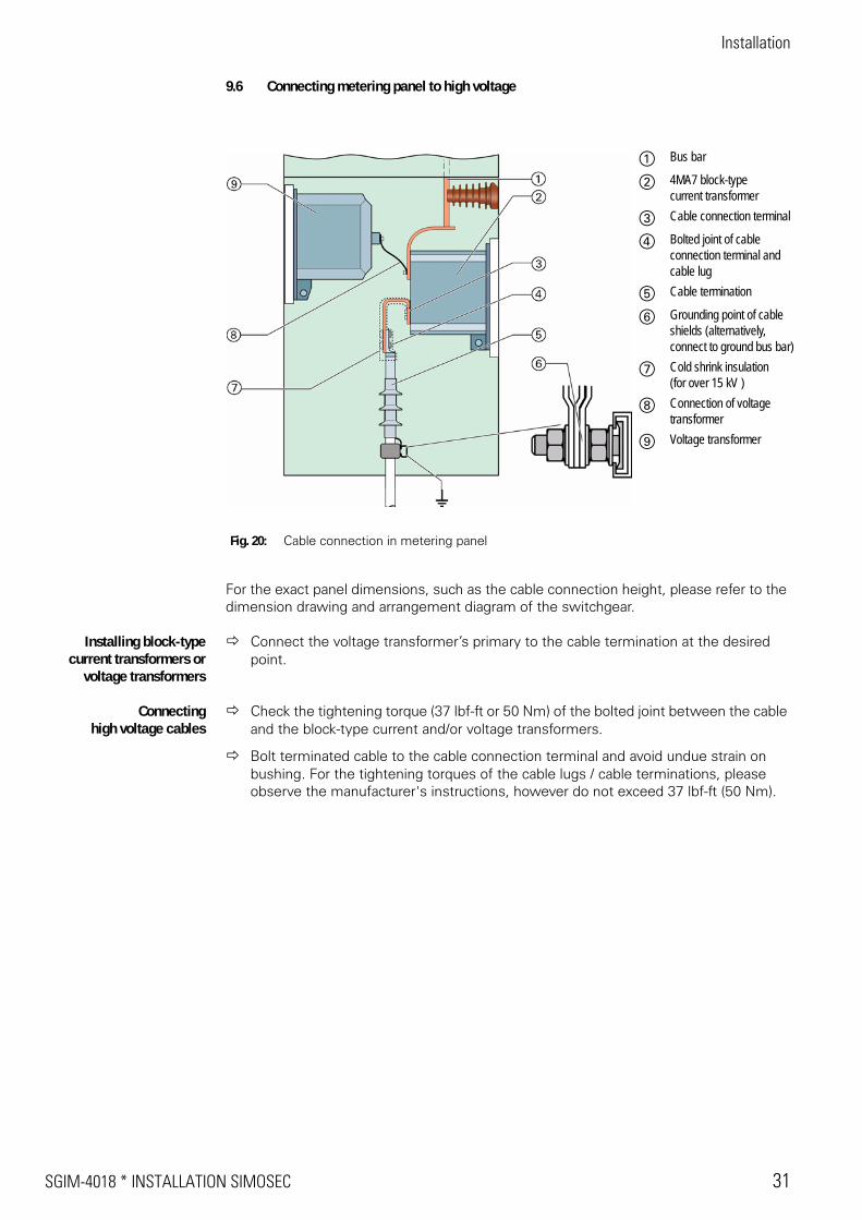
9.6 Connecting metering panel to high voltage
For the exact panel dimensions, such as the cable connection height, please refer to the dimension drawing and arrangement diagram of the switchgear.
Installing block-typecurrent transformers or
voltage transformers
Connect the voltage transformer’s primary to the cable termination at the desired point.
Connectinghigh voltage cables
Check the tightening torque (37 lbf-ft or 50 Nm) of the bolted joint between the cable and the block-type current and/or voltage transformers.
Bolt terminated cable to the cable connection terminal and avoid undue strain on bushing. For the tightening torques of the cable lugs / cable terminations, please observe the manufacturer's instructions, however do not exceed 37 lbf-ft (50 Nm).
Fig. 20: Cable connection in metering panel
a Bus bar
s 4MA7 block-typecurrent transformer
d Cable connection terminal
f Bolted joint of cableconnection terminal and cable lug
g Cable termination
h Grounding point of cable shields (alternatively,connect to ground bus bar)
j Cold shrink insulation(for over 15 kV )
k Connection of voltage transformer
l Voltage transformer
Installation
32 INSTALLATION SIMOSEC * SGIM-4018
10 Installing and connecting low voltage equipment
10.1 Installing secondary cables
The secondary cables are routed above the control compartment behind the screwed-on cover.
The secondary cables can be installed directly into the terminal connection compartment either from above through an entrance bushing or conduit fitting or from below through a flexible metal conduit (not furnished) arranged along the switchgear frame.
Please observe the correct polarity of the secondary leads of the window-type current transformers to be connected.
10.2 Connecting low voltage wiring
Connect all customer low voltage wiring according to the terminal plug and cable designations of the circuit diagrams of the switchgear.
10.3 Connecting the space heater
The individual panels of SIMOSEC switchgear are equipped with a space heater to prevent condensation.
Connect the space heater terminal according to the circuit diagrams for the switchgear.
Fig. 21: Cable routing for customer low voltage wiring
a Panel
s Cover, screwed on
d Entry for secondary cables
f Metal duct for secondary cables (option)
g Terminal connection compartment for customer low voltage wiring
h Low voltage compartment
j Control compartment
Rating 75 W for panels up to 500 mm width 100 W for panels > 500 mm
SGIM-4018 * INSTALLATION SIMOSEC 33
Installation
11 Switchgear extension
If required, installed switchgear can be extended with additional panels, or the existing panel configuration can be modified. After disconnecting and grounding the electric circuits, and after discharging any stored-energy in operating mechanisms, additional panels can be installed and connected. The procedure to be followed for switchgear extension is the same as for first installation
12 Placing SIMOSEC switchgear into service
12.1 Safety instructions
The correct and safe operation of this switchgear is conditional on:
• Proper transportation
• Correct storage
• Correct assembly and installation
• Careful operation in accordance with established procedures which comply with appli-cable codes and regulations
• Use of proper Personal Protective Equipment (PPE) (see NFPA 70E)
12.2 Instructing the operating personnel
The operating personnel should have these instructions available.
Instruct operating personnel in theory and practice of switchgear operation.
Ensure that the operating personnel are familiar with all operational details when placing equipment into service.
12.3 Checking the assembly work and the accessories
Accessories supplied with the equipment:
• Operating instructions
• Operating levers for three-position switch
• Double-bit keys (if necessary)
• Circuit diagrams
• Voltage detector or voltage detection system
Ensure that the above listed accessories are easily accessible.
Ensure that the assembly work has been performed correctly (see sections 8 - 10).
Ensure that all covers have been installed and enclosure hardware torqued to the correct values.
Ensure that all electrical connections have been torqued to the correct values.
Installation
34 INSTALLATION SIMOSEC * SGIM-4018
12.4 Final work
Visual inspection ofswitchgear
Check data on the rating plates according to the circuit diagrams.
Close all covers/doors.
Check safety/warning labels provided at the switchgear.
Clean the switchgear thoroughly. Remove all foreign matter. Clean all insulation with a lint-free cloth
Checking the accessories 12.5 Testing the switchgear electrically
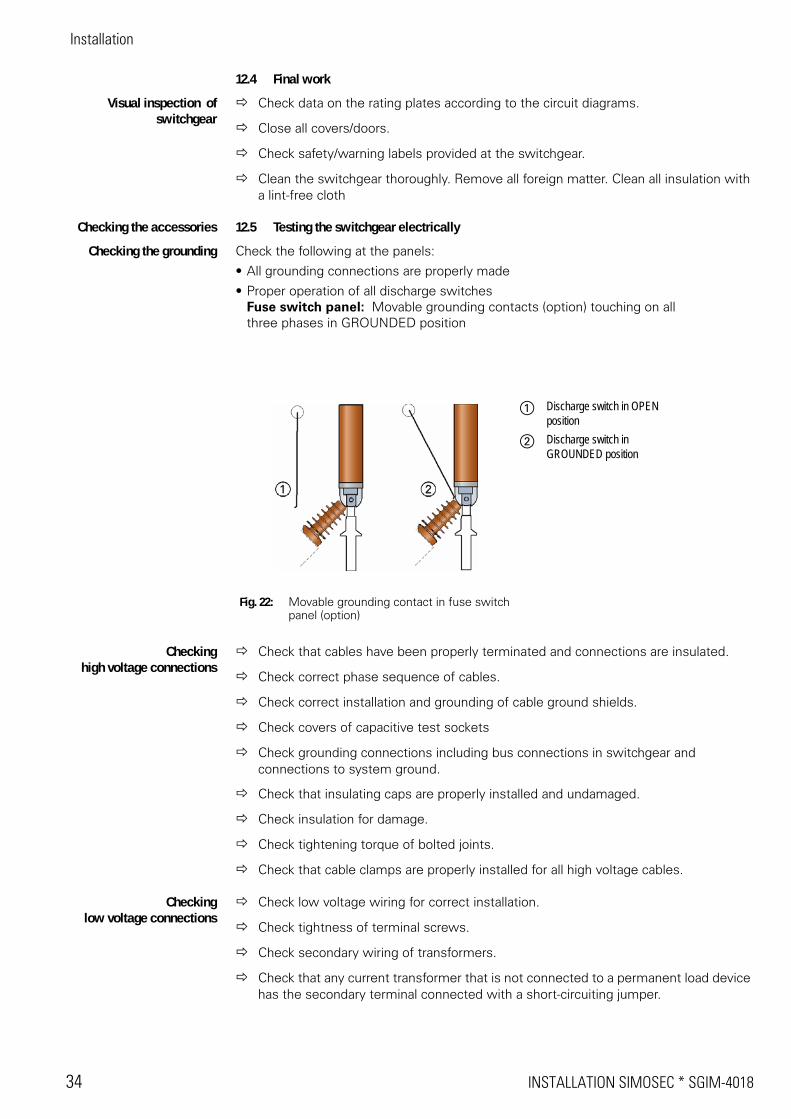
Checking the grounding Check the following at the panels:
• All grounding connections are properly made
• Proper operation of all discharge switchesFuse switch panel: Movable grounding contacts (option) touching on all three phases in GROUNDED position
Checkinghigh voltage connections
Check that cables have been properly terminated and connections are insulated.
Check correct phase sequence of cables.
Check correct installation and grounding of cable ground shields.
Check covers of capacitive test sockets
Check grounding connections including bus connections in switchgear and connections to system ground.
Check that insulating caps are properly installed and undamaged.
Check insulation for damage.
Check tightening torque of bolted joints.
Check that cable clamps are properly installed for all high voltage cables.
Checkinglow voltage connections
Check low voltage wiring for correct installation.
Check tightness of terminal screws.
Check secondary wiring of transformers.
Check that any current transformer that is not connected to a permanent load device has the secondary terminal connected with a short-circuiting jumper.
Fig. 22: Movable grounding contact in fuse switch panel (option)
a Discharge switch in OPEN position
s Discharge switch in GROUNDED position
SGIM-4018 * INSTALLATION SIMOSEC 35
Installation
12.6 Operating the switchgear for test
SIMOSEC switchgear is operated mechanically and electrically for test at the factory. Before commissioning, operate the switchgear again mechanically and electrically for test.
Mechanical operation The panels are delivered from the factory with all switching devices in "GROUNDED" position, and the closing and opening springs of the stored-energy mechanisms partially charged.
Operate the different switching options of each panel several times.
Switch the three-position switches several times to each position (CLOSED, OPEN, and GROUNDED), verifying the correct indication of the associated switch position indicators at the same time.
Test interlocking conditions of each switching option (without using excessive force).
The switch positions of the SIMOSEC switchgear are described in the operating instructions
Testing low voltage system Check the auxiliary circuits according to the circuit diagram and manual.
Switch on control voltage using an external source.
Check the indicators according to the circuit diagram and the mimic diagram of the switchgear.
Check the control elements according to the circuit diagram and the mimic diagram of the switchgear.
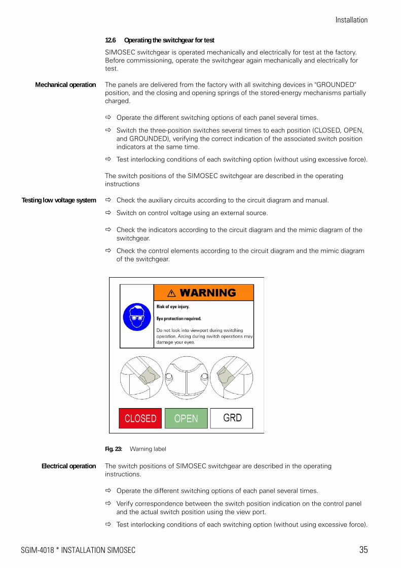
Fig. 23: Warning label
Electrical operation The switch positions of SIMOSEC switchgear are described in the operating instructions.
Operate the different switching options of each panel several times.
Verify correspondence between the switch position indication on the control panel and the actual switch position using the view port.
Test interlocking conditions of each switching option (without using excessive force).
Installation
36 INSTALLATION SIMOSEC * SGIM-4018
12.7 Testing
Simosec switchgear is well prepared to fulfill the following tests:
Following tests (proposal) should be made on the equipment (remark manufacturers and local prescriptions):
• An insulation resistance test is made on the high voltage circuit to be sure that all con-nections made in the field are properly insulated. An insulation resistance test is also advisable on the control circuit.
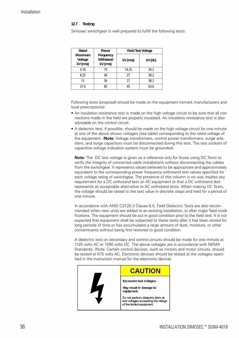
• A dielectric test, if possible, should be made on the high voltage circuit for one minute at one of the above shown voltages (see table) corresponding to the rated voltage of the equipment. (Note: Voltage transformers, control power transformers, surge arre-sters, and surge capacitors must be disconnected during this test. The test sockets of capacitive voltage indication system must be grounded).
Note: The DC test voltage is given as a reference only for those using DC Tests to verify the integrity of connected cable installations without disconnecting the cables from the switchgear. It represents values believed to be appropriate and approximately equivalent to the corresponding power frequency withstand test values specified for each voltage rating of switchgear. The presence of this column in no way implies any requirement for a DC withstand test on AC equipment or that a DC withstand test represents an acceptable alternative to AC withstand tests. When making DC Tests, the voltage should be raised to the test value in discrete steps and held for a period of one minute.
In accordance with ANSI C37.20.3 Clause 6.5, Field Dielectric Tests are also recom-mended when new units are added to an existing installation, or after major field modi-fications. The equipment should be put in good condition prior to the field test. It is not expected that equipment shall be subjected to these tests after it has been stored for long periods of time or has accumulated a large amount of dust, moisture, or other contaminants without being first restored to good condition.
A dielectric test on secondary and control circuits should be made for one minute at 1125 volts AC or 1590 volts DC. The above voltages are in accordance with NEMA Standards. (Note: Certain control devices, such as motors and motor circuits, should be tested at 675 volts AC. Electronic devices should be tested at the voltages speci-fied in the instruction manual for the electronic device).
RatedMaximum
VoltagekV (rms)
PowerFrequencyWithstandkV (rms)
Field Test Voltage
kV (rms) kV (dc)
4.76 19 14.25 20.28.25 36 27 38.215 36 27 38.2
27.6 60 45 63.6
SGIM-4018 * INSTALLATION SIMOSEC 37
Installation
12.8 Connecting operating voltage (high voltage)
The connection is conditional on complete and trouble-free commissioning
Switch all switching devices to "OPEN" position.
Ground cable feeders without connected high voltage cables at the feeder, and secure the grounding switch against de-grounding (opening).
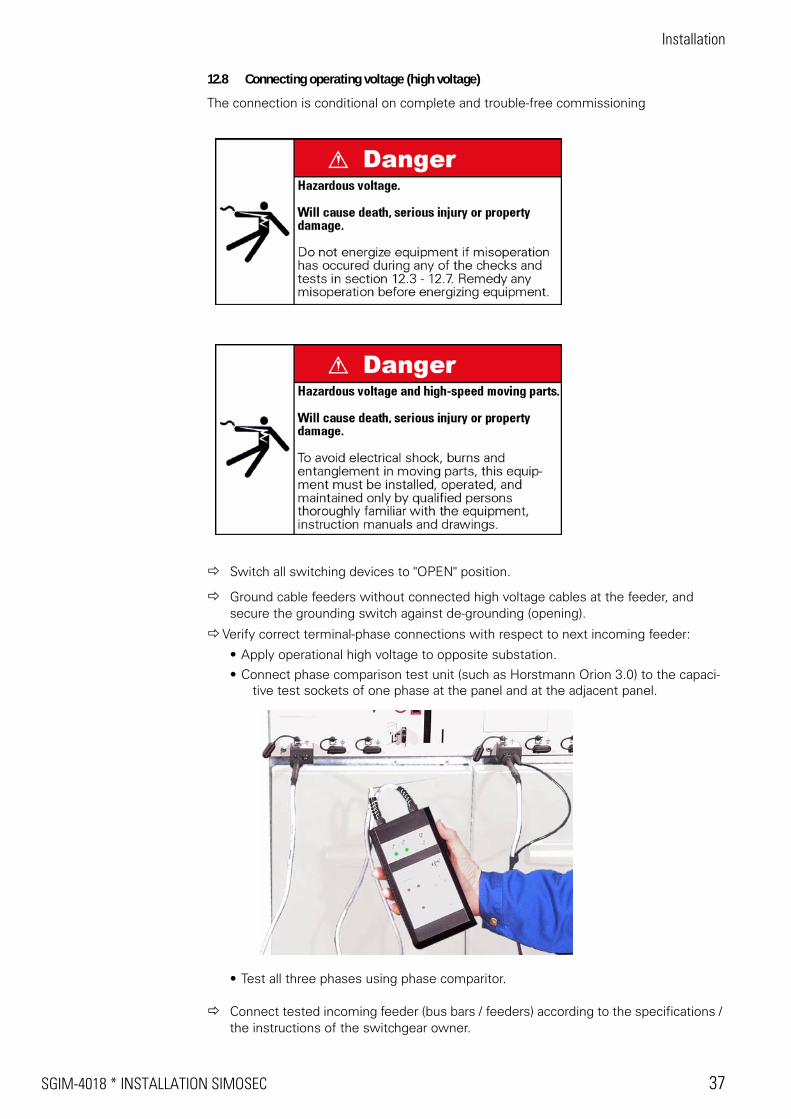
Verify correct terminal-phase connections with respect to next incoming feeder:
• Apply operational high voltage to opposite substation.
• Connect phase comparison test unit (such as Horstmann Orion 3.0) to the capaci-tive test sockets of one phase at the panel and at the adjacent panel.
• Test all three phases using phase comparitor.
Connect tested incoming feeder (bus bars / feeders) according to the specifications / the instructions of the switchgear owner.
Operation
38 OPERATION SIMOSEC * SGIM-4018
Operation
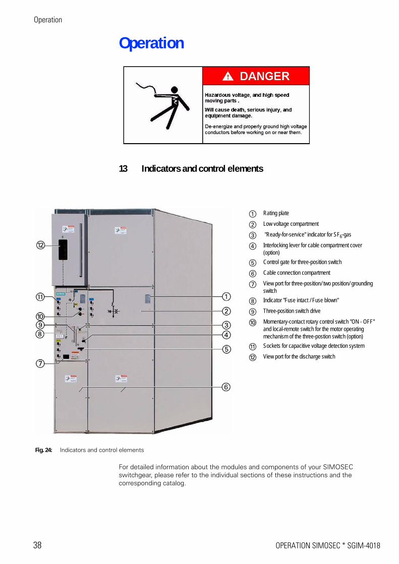
13 Indicators and control elements
For detailed information about the modules and components of your SIMOSEC switchgear, please refer to the individual sections of these instructions and the corresponding catalog.
Fig. 24: Indicators and control elements
a Rating plate
s Low voltage compartment
d "Ready-for-service" indicator for SF6-gas
f Interlocking lever for cable compartment cover (option)
g Control gate for three-position switch
h Cable connection compartment
j View port for three-position/ two position/ grounding switch
k Indicator "Fuse intact / Fuse blown"
l Three-position switch drive
; Momentary-contact rotary control switch "ON - OFF" and local-remote switch for the motor operating mechanism of the three-postion switch (option)
A Sockets for capacitive voltage detection system
S View port for the discharge switch
SGIM-4018 * OPERATION SIMOSEC 39
Operation
14 To be observed for operation
Before operation, always verify readiness for service of the panels to be operated.
14.1 Verification of readiness for service
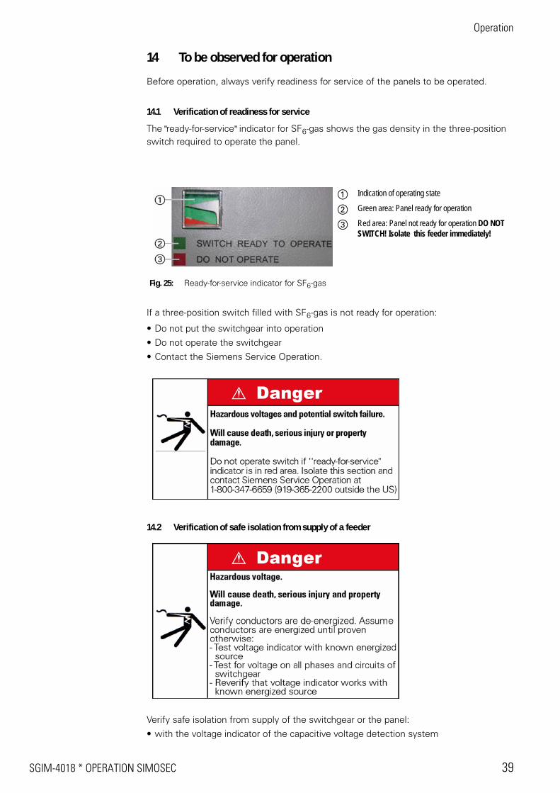
The "ready-for-service" indicator for SF6-gas shows the gas density in the three-position switch required to operate the panel.
If a three-position switch filled with SF6-gas is not ready for operation:
• Do not put the switchgear into operation
• Do not operate the switchgear
• Contact the Siemens Service Operation.
14.2 Verification of safe isolation from supply of a feeder
Verify safe isolation from supply of the switchgear or the panel:
• with the voltage indicator of the capacitive voltage detection system
Fig. 25: Ready-for-service indicator for SF6-gas
a Indication of operating state
s Green area: Panel ready for operation
d Red area: Panel not ready for operation DO NOT SWITCH! Isolate this feeder immediately!
Operation
40 OPERATION SIMOSEC * SGIM-4018
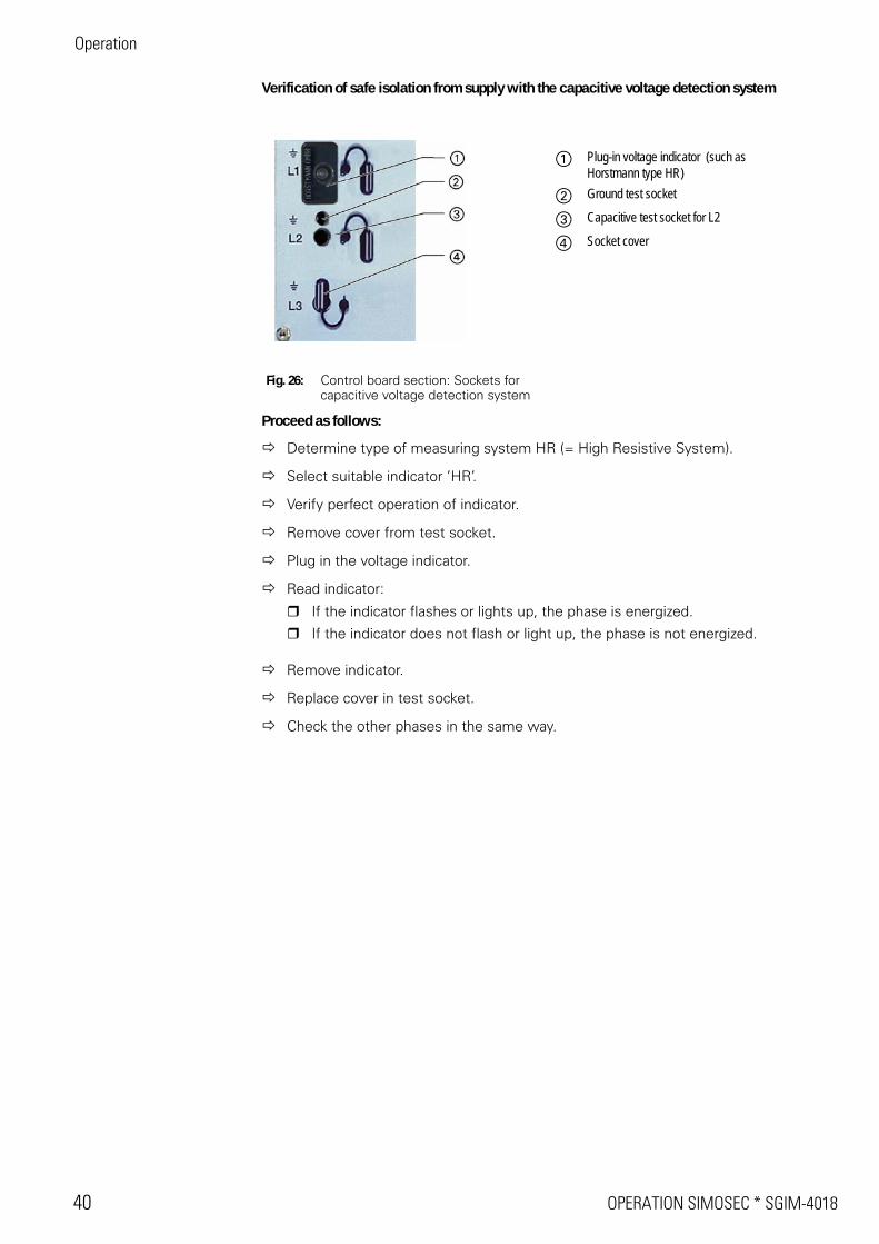
Verification of safe isolation from supply with the capacitive voltage detection system
Proceed as follows:
Determine type of measuring system HR (= High Resistive System).
Select suitable indicator ’HR’.
Verify perfect operation of indicator.
Remove cover from test socket.
Plug in the voltage indicator.
Read indicator:
If the indicator flashes or lights up, the phase is energized.
If the indicator does not flash or light up, the phase is not energized.
Remove indicator.
Replace cover in test socket.
Check the other phases in the same way.
Fig. 26: Control board section: Sockets for capacitive voltage detection system
a Plug-in voltage indicator (such as Horstmann type HR)
s Ground test socket
d Capacitive test socket for L2
f Socket cover
SGIM-4018 * OPERATION SIMOSEC 41
Operation
15 Operating the three-position switch
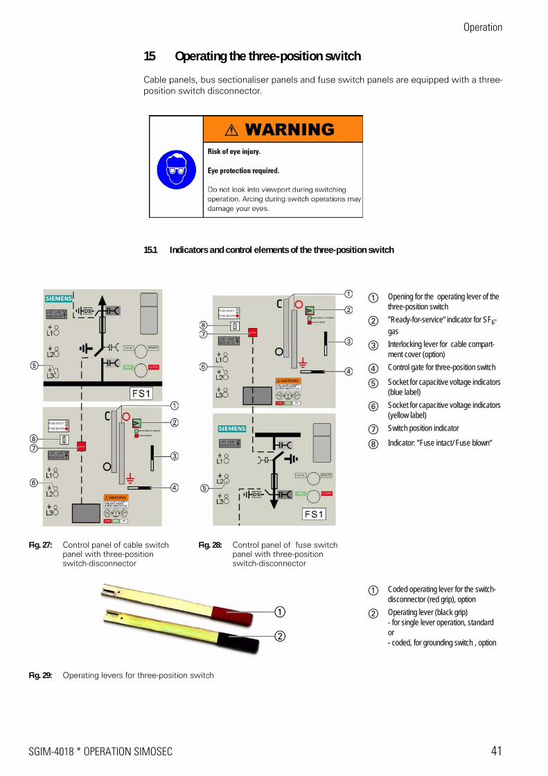
Cable panels, bus sectionaliser panels and fuse switch panels are equipped with a three-position switch disconnector.
15.1 Indicators and control elements of the three-position switch
Fig. 27: Control panel of cable switch panel with three-position switch-disconnector
Fig. 28: Control panel of fuse switch panel with three-position switch-disconnector
a Opening for the operating lever of the three-position switch
s ’’Ready-for-service“ indicator for SF6-gas
d Interlocking lever for cable compart-ment cover (option)
f Control gate for three-position switch
g Socket for capacitive voltage indicators (blue label)
h Socket for capacitive voltage indicators (yellow label)
j Switch position indicator
k Indicator: ’’Fuse intact/ Fuse blown“
Fig. 29: Operating levers for three-position switch
a Coded operating lever for the switch-disconnector (red grip), option
s Operating lever (black grip)- for single lever operation, standardor- coded, for grounding switch , option
Operation
42 OPERATION SIMOSEC * SGIM-4018
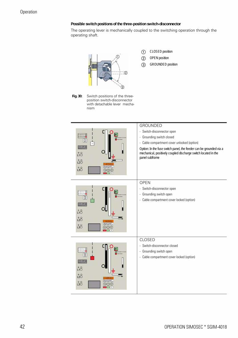
Possible switch positions of the three-position switch-disconnector
The operating lever is mechanically coupled to the switching operation through the operating shaft.
Fig. 30: Switch positions of the three-position switch-disconnector with detachable lever mecha-nism
a CLOSED position
s OPEN position
d GROUNDED position
GROUNDED- Switch-disconnector open
- Grounding switch closed
- Cable compartment cover unlocked (option)
Option: In the fuse switch panel, the feeder can be grounded via a mechanical, positively coupled discharge switch located in the panel subframe
OPEN- Switch-disconnector open
- Grounding switch open
- Cable compartment cover locked (option)
CLOSED- Switch-disconnector closed
- Grounding switch open
- Cable compartment cover locked (option)
SGIM-4018 * OPERATION SIMOSEC 43
Operation
15.2 Preconditions for operation
Preconditions for operating the three-position switch:
• Cable compartment cover installed
• Switchgear ‘‘ready for service“
• Operating lever available
• Control gate unlocked
15.3 Switching the three-position switch to CLOSED position
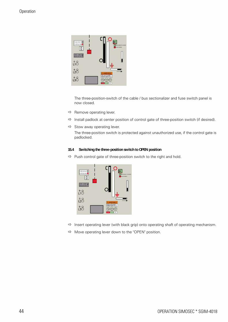
Push control gate of three-position switch to the right and hold.
Insert operating lever (with black grip) onto operating shaft of operating mechanism.
Move operating lever up to the "CLOSED" position.
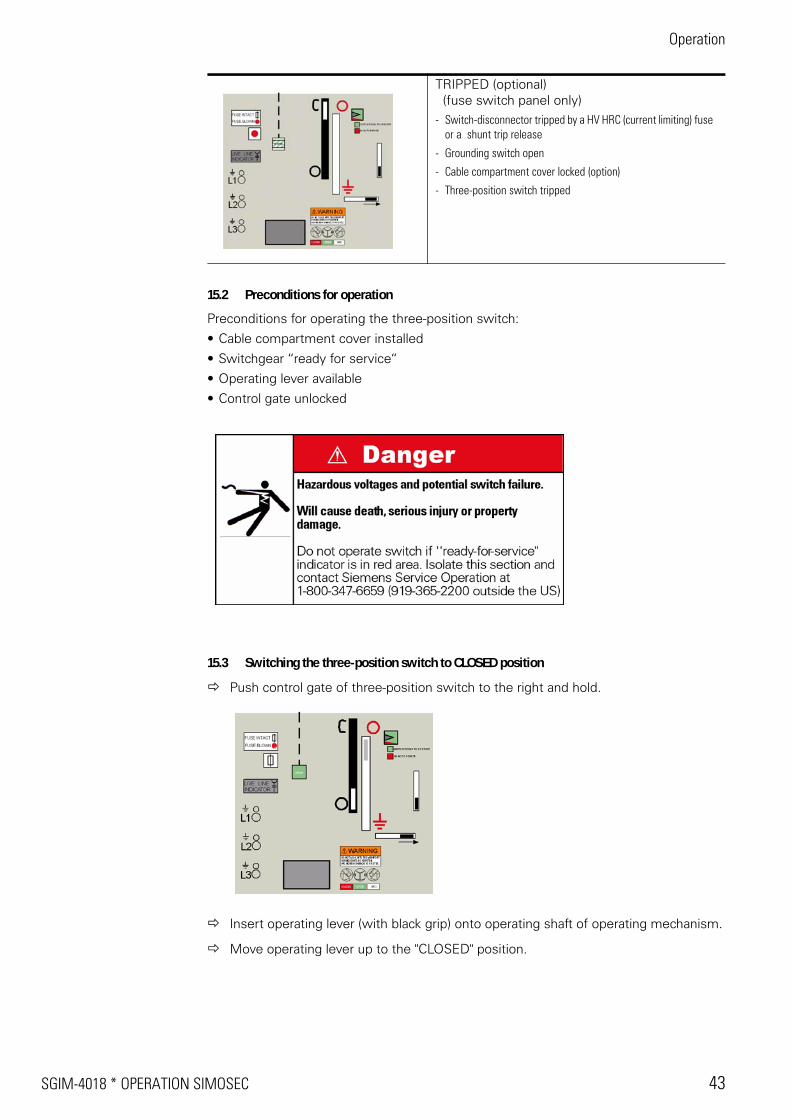
TRIPPED (optional) (fuse switch panel only)- Switch-disconnector tripped by a HV HRC (current limiting) fuse
or a shunt trip release
- Grounding switch open
- Cable compartment cover locked (option)
- Three-position switch tripped
Operation
44 OPERATION SIMOSEC * SGIM-4018
The three-position-switch of the cable / bus sectionalizer and fuse switch panel is now closed.
Remove operating lever.
Install padlock at center position of control gate of three-position switch (if desired).
Stow away operating lever.
The three-position switch is protected against unauthorized use, if the control gate is padlocked.
15.4 Switching the three-position switch to OPEN position
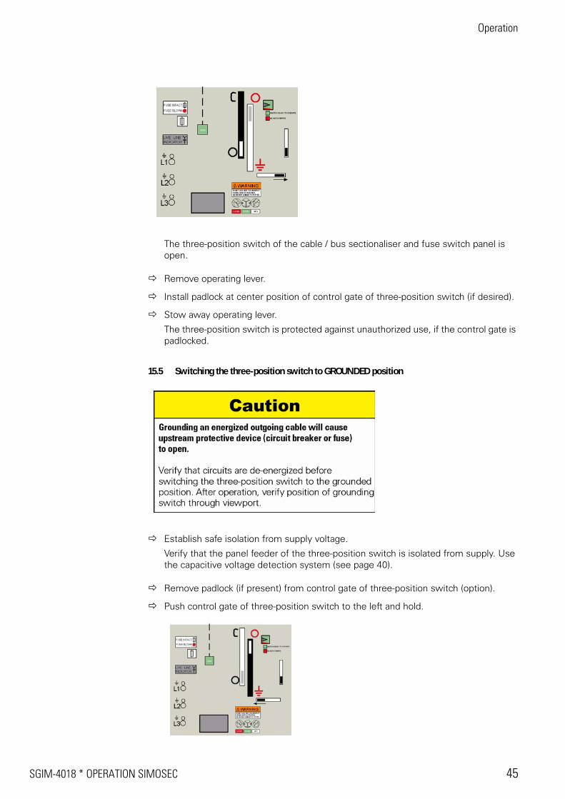
Push control gate of three-position switch to the right and hold.
Insert operating lever (with black grip) onto operating shaft of operating mechanism.
Move operating lever down to the "OPEN" position.
SGIM-4018 * OPERATION SIMOSEC 45
Operation
The three-position switch of the cable / bus sectionaliser and fuse switch panel is open.
Remove operating lever.
Install padlock at center position of control gate of three-position switch (if desired).
Stow away operating lever.
The three-position switch is protected against unauthorized use, if the control gate is padlocked.
15.5 Switching the three-position switch to GROUNDED position
Establish safe isolation from supply voltage.
Verify that the panel feeder of the three-position switch is isolated from supply. Use the capacitive voltage detection system (see page 40).
Remove padlock (if present) from control gate of three-position switch (option).
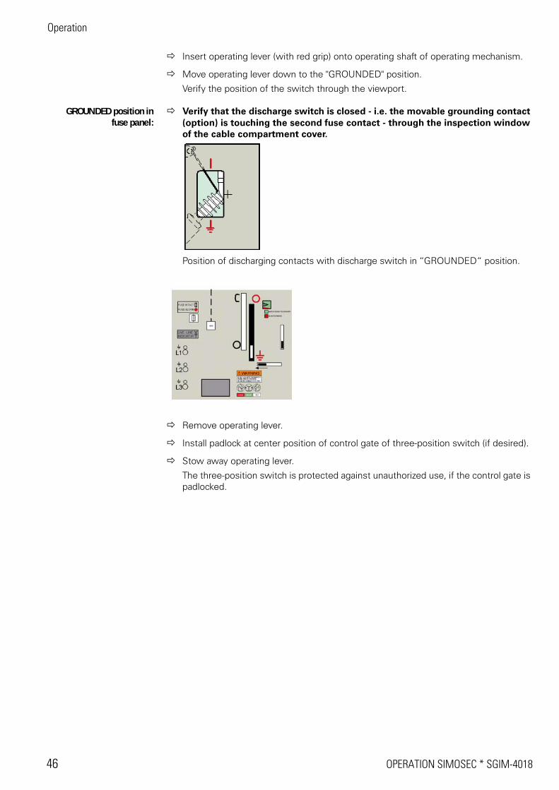
Push control gate of three-position switch to the left and hold.
Operation
46 OPERATION SIMOSEC * SGIM-4018
Insert operating lever (with red grip) onto operating shaft of operating mechanism.
Move operating lever down to the "GROUNDED" position.
Verify the position of the switch through the viewport.
GROUNDED position infuse panel:
Verify that the discharge switch is closed - i.e. the movable grounding contact (option) is touching the second fuse contact - through the inspection window of the cable compartment cover.
Position of discharging contacts with discharge switch in ‘‘GROUNDED“ position.
Remove operating lever.
Install padlock at center position of control gate of three-position switch (if desired).
Stow away operating lever.
The three-position switch is protected against unauthorized use, if the control gate is padlocked.
SGIM-4018 * OPERATION SIMOSEC 47
Operation
15.6 Switching the three-position switch from GROUNDED to OPEN position
Obtain clearance for removal of ground in accordance with established procedu-res for lockout-tagout complying with OSHA regulations and NFPA 70E.
• Verify that all work requiring grounding has been completed.
• Verify that all personnel are clear of conductors.
• Verify that any temporary grounds or short-circuits have been removed.
• Verify that all covers and doors have been closed.
Remove padlock (if present) from control gate of three-position switch.
Push control gate of three-position switch to the left and hold.
Insert operating lever (with red grip) onto operating shaft of operating mechanism.
Move operating lever up to the "OPEN" position.
OPEN position in fuseswitch panel
Verify that the discharge switch is in OPEN position - i.e. the movable grounding contact (option) is not touching the second fuse contact - through the inspection window of the cable compartment cover.
Position of grounding contacts with grounding switch in OPEN position.
Remove operating lever.
Install padlock at center position of control gate of three-position switch (if desired).
Operation
48 OPERATION SIMOSEC * SGIM-4018
Stow away operating lever.
The three-position switch is protected against unauthorized use, if the control gate is padlocked.
15.7 Switching the three-position switch with FII-Protection-System (option)
The Fuse-Installed-Intact-Protection-System (FII-Protection-System) could be installed in fuse switch panels. It prevents to switch the three-position switch to CLOSED position if only one fuse is blown or not installed. To switch the three-position switch to OPEN position is possible if the FII-Protection-System is active.
Switch to CLOSED position The shutter of the FII-Protection-System is vissible in the slot for closing/opening of the three-position switch.
Fig. 31: Shuttter of FII-Protection-System
To switch the three-position to CLOSED position is blocked by the shutter.
Fig. 32: Switching to CLOSED position blocked by shutter
Check if fuses are blown or not installed.
Replace or install fuses (see "Maintenance" 13.4, page 50).
Check if the shutter of the FII-Protection-System is still vissible in the slot for closing/opening of the three-position switch.
Switch the three-position switch to CLOSED position.
SGIM-4018 * OPERATION SIMOSEC 49
Operation
Switch to OPEN position Switching the three-position switch to OPEN position is always possible even if the FII-Protection-System is active or not.
Fig. 33: Switching to OPEN position is always possible
Switch the three-position switch to OPEN position.
Check if fuses are blown or not installed.
Replace or install fuses (see "Maintenance" 13.4, page 50).
Check if the shutter of the FII-Protection-System is still vissible in the slot for closing/opening of the three-position switch.
Operation
50 OPERATION SIMOSEC * SGIM-4018
16 Operating the make-proof grounding switch
Panels with make-proof grounding switch:
• Cable grounding panel CG
• Bus bar grounding panel BG, CG
16.1 Indicators and control elements of the make-proof grounding switch
Fig. 34: Control panel of cablegrounding panel withmake-proof grounding switch
Fig. 35: Control panel of bus bargrounding panel withmake-proof grounding switch
a Opening for the operating lever mecha-nism of the make-proof grounding switch
s ‘‘Ready-for-service“ indicator for SF6-gas
d Control gate for fault make grounding switch
f Socket for capacitive voltage indicators
g Switch position indicator
SGIM-4018 * OPERATION SIMOSEC 51
Operation
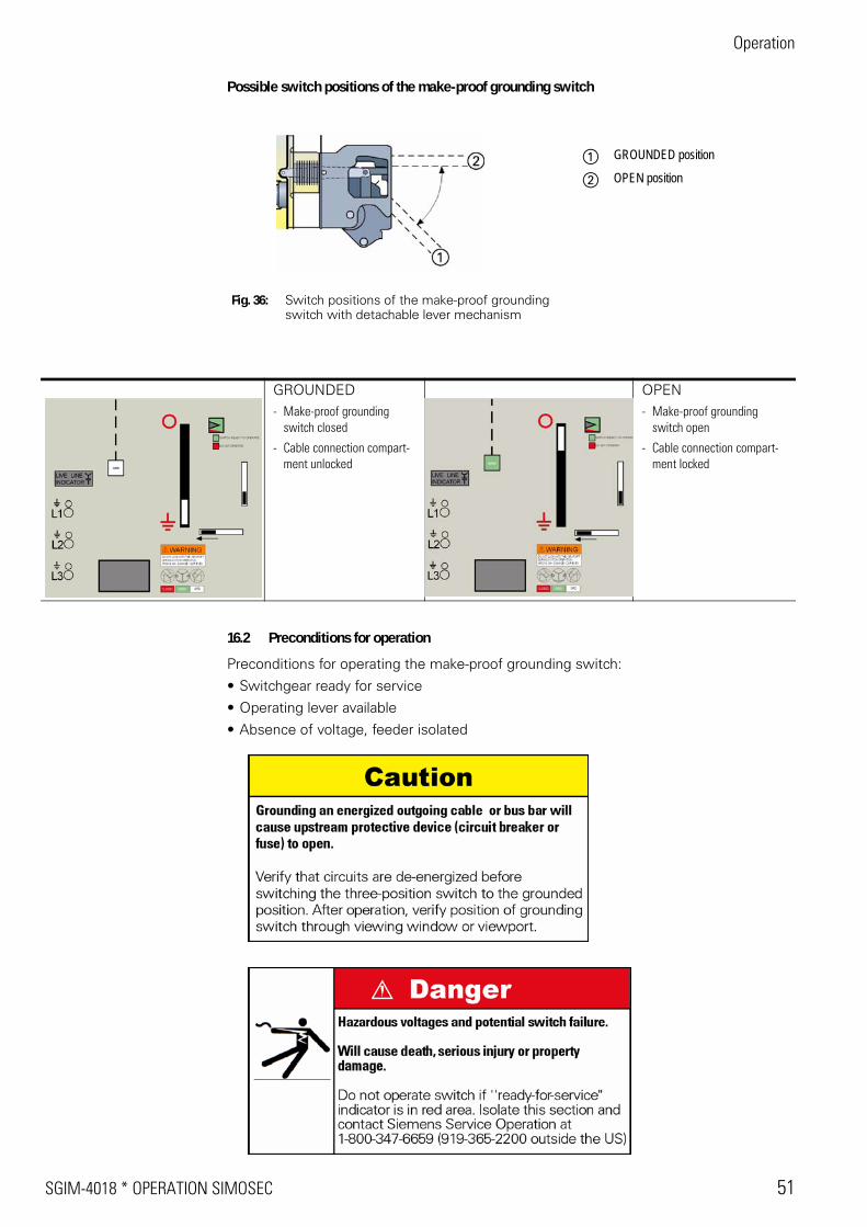
Possible switch positions of the make-proof grounding switch
16.2 Preconditions for operation
Preconditions for operating the make-proof grounding switch:
• Switchgear ready for service
• Operating lever available
• Absence of voltage, feeder isolated
Fig. 36: Switch positions of the make-proof grounding switch with detachable lever mechanism
a GROUNDED position
s OPEN position
GROUNDED- Make-proof grounding
switch closed
- Cable connection compart-ment unlocked
OPEN- Make-proof grounding
switch open
- Cable connection compart-ment locked
Operation
52 OPERATION SIMOSEC * SGIM-4018
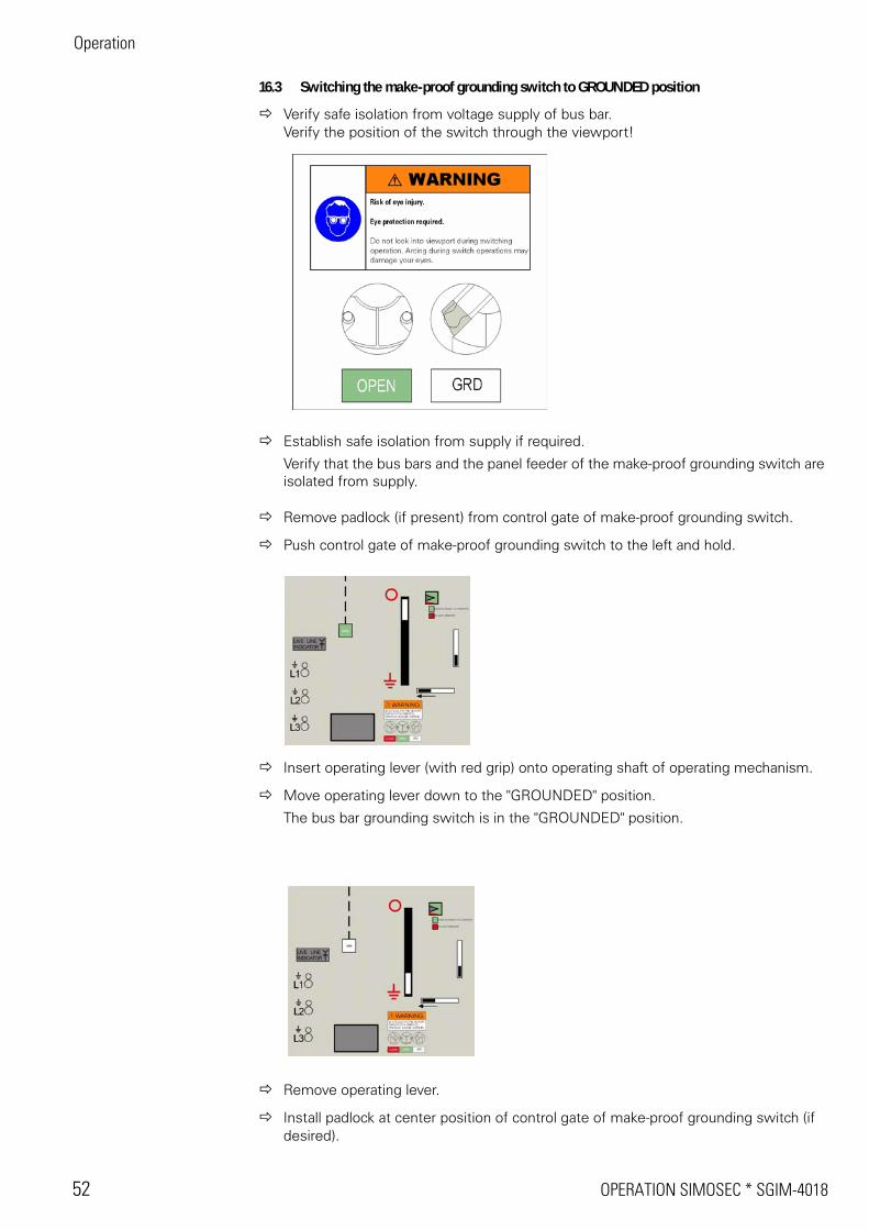
16.3 Switching the make-proof grounding switch to GROUNDED position
Verify safe isolation from voltage supply of bus bar.Verify the position of the switch through the viewport!
Establish safe isolation from supply if required.
Verify that the bus bars and the panel feeder of the make-proof grounding switch are isolated from supply.
Remove padlock (if present) from control gate of make-proof grounding switch.
Push control gate of make-proof grounding switch to the left and hold.
Insert operating lever (with red grip) onto operating shaft of operating mechanism.
Move operating lever down to the "GROUNDED" position.
The bus bar grounding switch is in the "GROUNDED" position.
Remove operating lever.
Install padlock at center position of control gate of make-proof grounding switch (if desired).
SGIM-4018 * OPERATION SIMOSEC 53
Operation
Stow away operating lever.
The make-proof grounding switch is protected against unauthorized use, if the control gate is padlocked.
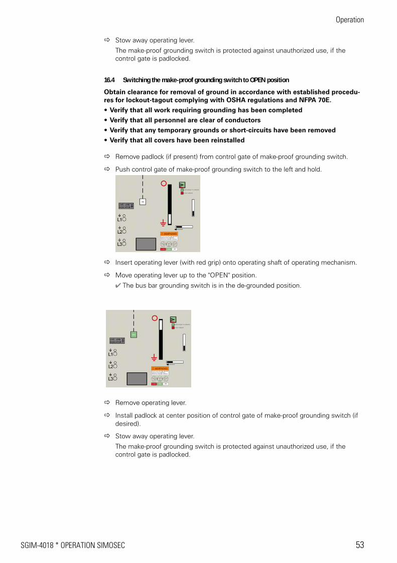
16.4 Switching the make-proof grounding switch to OPEN position
Obtain clearance for removal of ground in accordance with established procedu-res for lockout-tagout complying with OSHA regulations and NFPA 70E.
• Verify that all work requiring grounding has been completed
• Verify that all personnel are clear of conductors
• Verify that any temporary grounds or short-circuits have been removed
• Verify that all covers have been reinstalled
Remove padlock (if present) from control gate of make-proof grounding switch.
Push control gate of make-proof grounding switch to the left and hold.
Insert operating lever (with red grip) onto operating shaft of operating mechanism.
Move operating lever up to the "OPEN" position.
r The bus bar grounding switch is in the de-grounded position.
Remove operating lever.
Install padlock at center position of control gate of make-proof grounding switch (if desired).
Stow away operating lever.
The make-proof grounding switch is protected against unauthorized use, if the control gate is padlocked.
Operation
54 OPERATION SIMOSEC * SGIM-4018
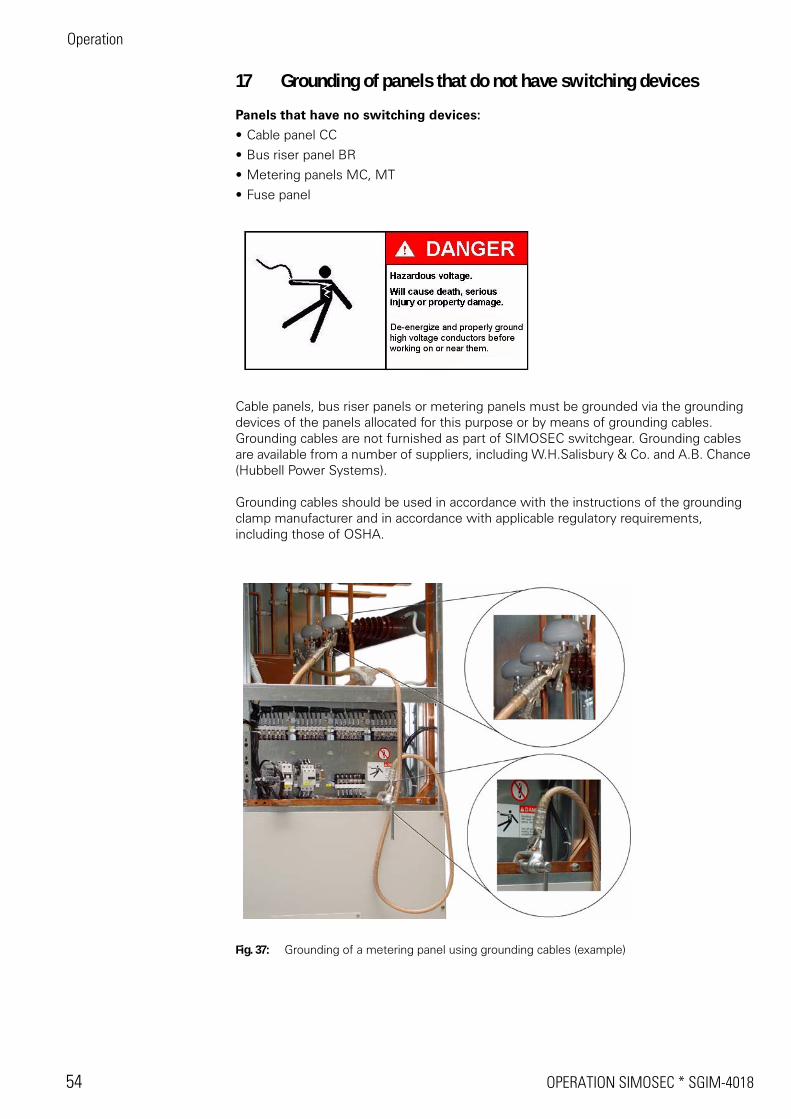
17 Grounding of panels that do not have switching devices
Panels that have no switching devices:
• Cable panel CC
• Bus riser panel BR
• Metering panels MC, MT
• Fuse panel
Cable panels, bus riser panels or metering panels must be grounded via the grounding devices of the panels allocated for this purpose or by means of grounding cables. Grounding cables are not furnished as part of SIMOSEC switchgear. Grounding cables are available from a number of suppliers, including W.H.Salisbury & Co. and A.B. Chance (Hubbell Power Systems).
Grounding cables should be used in accordance with the instructions of the grounding clamp manufacturer and in accordance with applicable regulatory requirements, including those of OSHA.
Fig. 37: Grounding of a metering panel using grounding cables (example)
SGIM-4018 * INDEX SIMOSEC 55
18 Index
AAccessories ..............................................................33Accessories - checking .............................................34Assembly work, checking before commissioning ....33Auxiliary means - installation ......................................9
BBus bar - installing ....................................................17Bus bar compartment - access ................................17Bus riser panel - grounding ......................................54
CCable panel - connecting to high voltage .................29Cable panel - grounding ...........................................54Cable shields - connecting .......................................23Checking gas density SF6-gas .................................39Connecting - high voltage .........................................37Control elements .....................................................38Control elements - make-proof grounding switch ....50Control elements - three-position switch .................41
EElectrical operation - test ..........................................35End wall - installing ..................................................13
FFII-Protection-System ...............................................48Fuse switch panel - connecting to high voltage .......30Fuse-Installed-Intact-Protection-System ..................48
GGas density SF6-gas - checking ...............................39Ground bus bar - installing .......................................20Grounding - checking ...............................................34
HHeater - connecting ..................................................32High voltage - connecting .........................................37High voltage cables - connecting .............................22
IIndicators ..................................................................38Installation ..................................................................6Installation - auxiliary means ......................................9Installation - final work .............................................34Installation - tools .......................................................9Installing panels ........................................................13Instructing the operating personnel .........................33Insulating caps - installing ........................................19
LLow voltage equipment - installing ..........................32Low voltage system - test ........................................35Low voltage wiring - connecting ..............................32
MMake-proof grounding switch - control elements ....50
Make-proof grounding switch - de-grounding ..........53Make-proof grounding switch - grounding ...............52Make-proof grounding switch - switch position indica-
tor ..........................................................................50Mechanical operation - test ......................................35Metering panel - connecting to high voltage ............31Metering panel - grounding ......................................54
OOperating levers - three-position switch ..................41Operating personnel, instructing ..............................33Operating switchgear for test ..................................35Operating voltage - connecting ................................37Operation .................................................................38
PPacking .....................................................................10Panel - installing .......................................................13Placing switchgear into service ................................33Power-frequency voltage test at site .......................36
RReady-for-service indicator .......................................39
SSafety instructions .............................................. 4, 33Secondary cables - installing ....................................32SF6-gas ....................................................................39Station ground to switchgear frame - connecting ....21Switch position indicator - make-proof grounding
switch ....................................................................50Switch position indicator - three-position switch .....41Switchgear - electrical test .......................................34Switchgear extension ...............................................33
TTest operation ..........................................................35Three-position switch - closing .................................43Three-position switch - control elements .................41Three-position switch - de-grounding .......................47Three-position switch - grounding ............................45Three-position switch - opening ...............................44Three-position switch - operating .............................41Three-position switch - operating levers ..................41Three-position switch - switch position indicator .....41Tools - installation .......................................................9Transport at site .......................................................10Transporting .............................................................10
UUnloading .................................................................10
WWindow type current transformers - mounting ........22

SGIM-4018 (new 08-2005) Printed in U.S.A. Siemens Power Transmission & Distribution, Inc.SIEMENS is a registered trademark of Siemens AG.
Siemens PowerTransmission & Distribution
P.O. Box 29503Raleigh, NC 27626-0503
s