medium voltage switchgear nes-h• iec 62271-200 for switchgear • iec 62271-102 for earthing...
TRANSCRIPT
MEDIUM VOLTAGESWITCHGEAR NES-HUp to 17.5 kV
www.alfanar.com

2
Contents
1 - Introduction to NES-H 4
a- NES-H Key Features 5
b- Standards 5
c- Quality Management 5
2 - NES-H in Networks 6
3 - Applications 7
4 - IEC Classification 8
a- IEC 62271-200 Replaces IEC 60298 8
b- Key Features of the new IEC 62271-200 10
5 - Product Breakdown 13
6 - Substations Arrangement 14
7 - Technical Data 16
8 - Configuration (Functional Units) 17
9 - Main Components 20
A - Vacuum Circuit BreakerVCB 20
1- Arc-quenching Media 20
2- Switching Devices 22
3- VCB Features and Technical Data 23
B - Instrument Transformers IT 27
1- Current Transformer 27
2- Voltage Transformer 27
3- CBCT 27
C - Power System Protection 28
1 - Protection Relay 28
a- Basic Requirements of Protection System 28
b- Relays 29
1- Protective Relays 29
• Overcurrent Relay 29
• Directional Overcurrent Relay 29
• Differential Relay 30
2- Auxiliary Relays 30
• Tripping Relays 30
• Monitoring Relays 31
• Contacts Multiplication Relays 31
D - High Speed Earthing Switch 31
10 - Type Test 32
11 - Order Form 34
4
1 - Introduction to NES-H
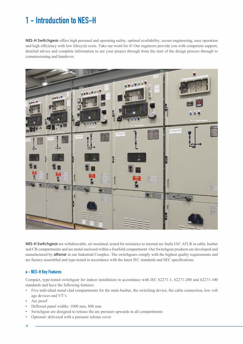
NES-H Switchgear offers high personal and operating safety, optimal availability, secure engineering, easy operation and high efficiency with low lifecycle costs. Take our word for it! Our engineers provide you with competent support, detailed advice and complete information to see your project through from the start of the design process through to commissioning and handover.
NES-H Switchgear are withdrawable, air-insulated, tested for resistance to internal arc faults IAC AFLR in cable, busbar and CB compartments and are metal enclosed within a fourfold compartment. Our Switchgear products are developed and manufactured by alfanar in our Industrial Complex. The switchgears comply with the highest quality requirements and are factory-assembled and type-tested in accordance with the latest IEC standards and SEC specifications.
a - NES-H Key Features
Compact, type-tested switchgear for indoor installation in accordance with IEC 62271-1, 62271-200 and 62271-100 standards and have the following features:• Five individual metal clad compartments for the main busbar, the switching device, the cable connection, low volt age devices and VT’s• Arc proof• Different panel widths: 1000 mm, 800 mm• Switchgear are designed to release the arc pressure upwards in all compartments• Optional: delivered with a pressure release cover

Highest personal and operating safety features• All electrical and mechanical operating procedures take place when the enclosure is closed• Maximized operating safety owing to serial production, complete mechanical interlocking system• Shutters automatically protect the isolating contacts when the unit is withdrawn• Make-proof earthing switches• High availability resulting from the quick exchange of the withdrawable units by means of the winch and hydraulic trolleys
Durable and geared for the future• Panels are air-insulated and use a minimum amount of insulant volumes• Ideal assembly is possible due to technical and economic factors• Spare parts are easily obtainable because of the use of standard insulators, standard instrument transformers, standard switching devices and standard copper sections
Meeting the highest quality requirements• State-of- art manufacturing techniques using a high precision laser cutting system which guarantees perfect dimensional accuracy• Distortion resistant cubicle frame made of top quality Alu-Zinc/GI sheet steel that is bolted together• Internal arc resistant, double sheet steel partitions between panels• Busbar partitioning from panel to panel• Electrostatic powder coating of the front door and side panels• Engineering and manufacturing in accordance with quality management system EN ISO 9001
b - Standards
NES-H switchgear and the main apparatus contained in it comply with the following Standards:• IEC 62271-1 for general purposes• IEC 62271-200 for switchgear• IEC 62271-102 for earthing switch• IEC 62271-100 for circuit-breakers• IEC 61850 Communication networks and systems for power utility automation• IEC 61869 Instrument Transformers• IEC 60529 Degrees of protection provided by enclosures• IEC 60947 Low-voltage switchgear and controlgear
c - Quality Management
NES-H units are produced with an integrated quality system carefully defined for all departments. During each stage of the manufacturing process we ensure that the NES-H units are built perfectly, and comply with adherence standards. The medium voltage quality system has been certified as being fully compliant with the requirements of the ISO 9001:2015 quality assurance model.
Quality ChecksThe quality checked carried out include a visual inspection and check of:• Mechanical sequence operations• Cabling check• Electrical sequence operations• Power frequency withstand voltage• Measurement of the resistance of the main circuits• Secondary insulation test
6
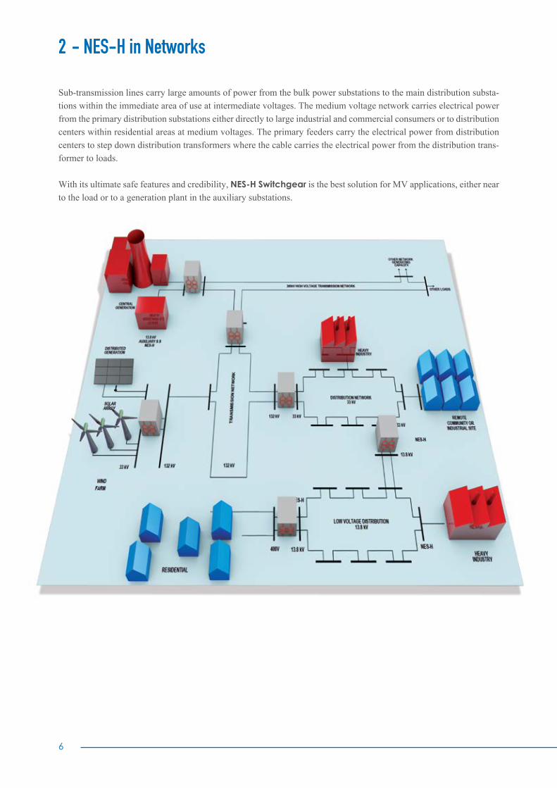
Sub-transmission lines carry large amounts of power from the bulk power substations to the main distribution substa-tions within the immediate area of use at intermediate voltages. The medium voltage network carries electrical power from the primary distribution substations either directly to large industrial and commercial consumers or to distribution centers within residential areas at medium voltages. The primary feeders carry the electrical power from distribution centers to step down distribution transformers where the cable carries the electrical power from the distribution trans-former to loads.
With its ultimate safe features and credibility, NES-H Switchgear is the best solution for MV applications, either near to the load or to a generation plant in the auxiliary substations.
2 - NES-H in Networks

3 - Applications
C - Energy: wind power plants, solar power plants, hydro power plants, secondary distribution networks, transformer substations etc.
A - Infrastructure and buildings: ports, railway stations, airports, hospitals, schools, hotels, malls, commercial centers, holiday resorts etc.
D - Special applications: high air pollution ar-eas, high humidity areas etc.
B - Industries: water, iron and steel, auto-motive, oil and gas etc.
8
At the end of the 1990’s, IEC committees decided to modify the switchgear standard, the new changes took effect in November 2003 and are known as IEC 62271-200.
Although the old IEC 60298 standard was helpful, new standards were required to cover the technological progress being made. The appearance of maintenance-free vacuum circuit-breakers, with operating cycles far exceeding the normal number, made frequent access to this circuit-breaker no longer of prime importance.
The vacuum arc-quenching principle is technologically so superior to other arc-quenching principles that the circuit-breaker can be fixed-mounted. This resulted in the first-time use of gas insulation with the important features of climat-ic independence, compactness and maintenance-free design. However, both technologies – the vacuum arc-quenching principle and gas insulation – were not adequately taken into account in the previous standard. a - IEC 200-62271 Replaces IEC 60298
The major difference between the two IEC Standards versions is that the old IEC was defining the switchgear from the construction principle which was not sufficient enough, whereas the present IEC 62271-200 takes into consideration the customer’s point of view and defines the switchgear on this basis.
4 - IEC Classification
Old IEC 60298 Definitions
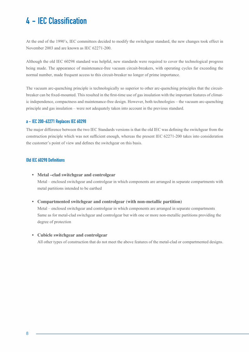
• Metal –clad switchgear and controlgear Metal – enclosed switchgear and controlgear in which components are arranged in separate compartments with metal partitions intended to be earthed • Compartmented switchgear and controlgear (with non-metallic partition) Metal – enclosed switchgear and controlgear in which components are arranged in separate compartments Same as for metal-clad switchgear and controlgear but with one or more non-metallic partitions providing the degree of protection • Cubicle switchgear and controlgear All other types of construction that do not meet the above features of the metal-clad or compartmented designs.
Cubicle
CompartmentedMetal-Clad
NO Subject Metal Clad Compartmented Cubicle1 No. of compartments >3 3 <3
2 Internal portions Metallic earthed Non metallic Metallic or not
3 Presence of bushings Yes possible No
4 Shutters which prevent access to live compartments
Yes YesYes, if 2
compartments
5 External covers Metallic earthed Metallic earthed Metallic earthed
Table 1 Major differences between switchgear types as per IEC 60298

10
b- Key features of the new IEC 200-62271
1 Changed dielectric requirements According to IEC 60298, 2 disruptive discharges were permitted in a series of 15 voltage impulses for the test with rated lightning impulse withstand voltage. According to the new standard, the series must be extended by another 5 voltage impulses if a disruptive discharge has occurred during the first 15 impulses. This can lead to a maximum of 25 voltage impulses, whereas the maximum number of permissible disruptive discharges is still 2.
2. Increased demands on the circuit breaker and earthing switch In contrast to the previous standard, the switching capacity test of both switching devices is no longer carried out as a pure device test. Instead, it is now mandatory to carry out the test in the corresponding switchgear panel. The switching capacity may get a negative influence from the different arrangement of the switchgear with contact arms, moving contacts, conductor bars, etc. For this reason, the test duties T10, T30, T60, T100s and T100a from the IEC 62271-100 standard are stipulated for the test of the circuit breaker inside the switchgear panel. In addition, the single phase and double earth fault tests are also carried out on the breaker inside the switchgear panel.
3. Newpartitionclassification The new partition classes PM (partitions metallic = partitions and shutters made of metal) or PI (partitions nonme tallic = partitions and shutters made of insulating material) now apply with respect to the protection against electric shock during access to the individual components. The assignment is no longer according to the construc tional description (metalclad, compartmented or cubicle-type), but according to operator-related criteria (Tables 1 and 2).
4. Loss of service continuity A category defining the possibility of keeping the other compartments and/or functional units energized when opening a main circuit compartment:
Loss of servicecontinuity category
When an accessible compartment ofthe switchgear is opened Constructional design
LSC 1The busbar and therefore the complete
switchgear must be isolated.No partitions within the panel, no panel
partition walls to adjacent panels.
LSC 2
LSC 2AThe incoming cable must be isolated. The busbar and the adjacent switchgear panels
can remain in operation.
Panel partition walls and isolating distance with compartmentalization to the busbar.
LSC 2BThe incoming cable, the busbar and the
adjacent switchgear panels can remain in operation.
Panel partition walls and isolating distance with compartmentalization to the busbar and to the
cable.
Table 1 Switchgear classification based on LSC
4 - IEC Classification

Figure 1LSC1: Compartments without any physical and electrical segregation
Circuit Breaker Compartment Feeder Compartment
Busbar Compartment Auxiliary compartment
B
A
A
B
Figure 2LSC 2A Busbar and apparatus compartments physically and electrically segregated
Figure 3LSC2B Busbar, feeder and apparatus compartments physically and electrically segregated
Circuit Breaker Compartment Feeder Compartment
Busbar Compartment
Auxiliary Compartment
B
C
A
Circuit Breaker Compartment Feeder Compartment
Busbar Compartment
Feeder Compartment
Auxiliary Compartment
B
C
D
A
A
D
C
B
A
C
B
12
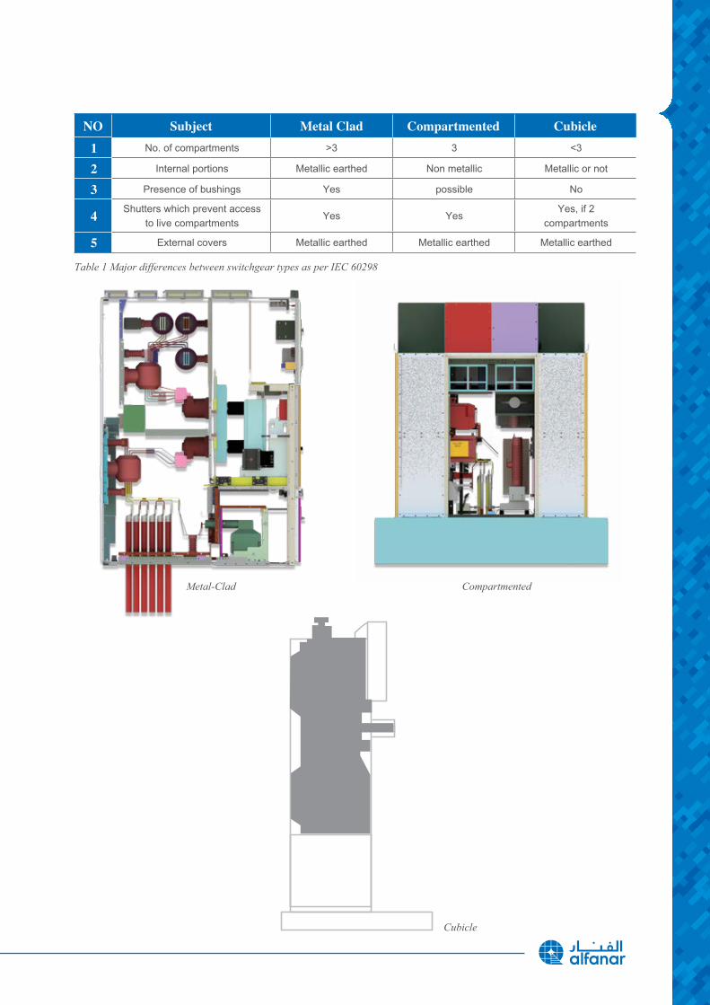
5. InternalArcclassificationaspernewIEC62271-200
• Under arc fault conditions, a huge amount of damage is caused to the equipment, and a significant injury hazard is posed to any personnel in the vicinity at the time of the fault • The arc arises when at least part of the current passes through a dielectric, usually air with maximum peak power up to 40 MW • Arc temperature up to 4 times the surface temperature of the sun (20,000°C) NOTE: The sun is approximately 5,500ºC • Light intensity more than 2,000 times that of normal office light
Significantly stricter changes have also been implemented for the new standard. The energy flow direction of the arc supply, the maximum number of permissible panels with the test in the end panel and the dependency of the ceiling height on the respective panel height have been redefined.
In addition, the following new criteria must always be completely fulfilled (no exceptions are permitted): 1. Covers and doors must remain closed. Limited deformations are accepted. 2. No fragmentation of the enclosure, no projection of small parts above 60 g weight. 3. No holes in the accessible sides up to a height of 2 meters. 4. Horizontal and vertical indicators must not ignite due to the effect of hot gases. 5. The enclosure must remain connected to its earthing parts.
For the internal arc classification of substations with and without a control aisle, the testing of the substation with installed switchgear is mandatory in the new IEC 62271-202 standard. The classification of the substation is only valid in combination with the switchgear used for the test. The classification cannot be transferred to a combination with another switchgear type as each switchgear behaves differently in the case of an internal arc (pressure relief equipment with different cross-sections and pickup pressures, different arcing conditions because of different conductor geometries).
The new IEC Standard classified the switchgear based on the accessibility to the switchgear and its compartments:
4 - IEC Classification
Type of accessibility
to a compartmentAccess features
Interlock-basedOpening for normal operation and
maintenance, e.g. fuse replacement
Access is controlled by the construction of the switchgear, i.e. integrated interlocks prevent
impermissible opening
Procedure-basedOpening for normal operation and
maintenance, e.g. fuse replacement.
Access control via a suitable procedure (work instruction of the operator) combined
with a locking device (lock).
Tool-basedOpening not for normal operation or
maintenance, e.g. cable testing.Access only with tool for opening, special
access procedure (instruction of the operator).
Non-accessibleOpening not possible / not intended for operator, opening can destroy the compartment. This
applies generally to the gas-filled compartments of gas-insulated switchgear. As the switchgear is maintenance-free and climate-independent, access is neither required nor possible.
Table 2 Accessibility to compartment

5 - Product Breakdown
1 Pressureflaps 9 Busbar2 Low voltage compartment 10 Spout bushing 3 Shutters 11 Current transformer4 VCB contacts 12 Main bushing 5 Relay 13 Insulation boot6 VCB door 14 Power cable7 Vaccum circuit breaker 15 Power cable compartment8 VT door 16 Voltage transformer
12
10
11
9
13
14
15
8
6
7
5
4
3
2
1
16
14
6 - Substations Arrangement
There are many different electrical bus system schemes available, the consumer should be aware about the main criteria during selection for any arrangement scheme: 1. Simplicity of system. 2. Easy maintenance of different equipment. 3. Minimizing the outage during maintenance. 4. Future provision of extension with growth of demand. 5. Optimizing the selection of busbar arrangement scheme so that it gives maximum return from the system.
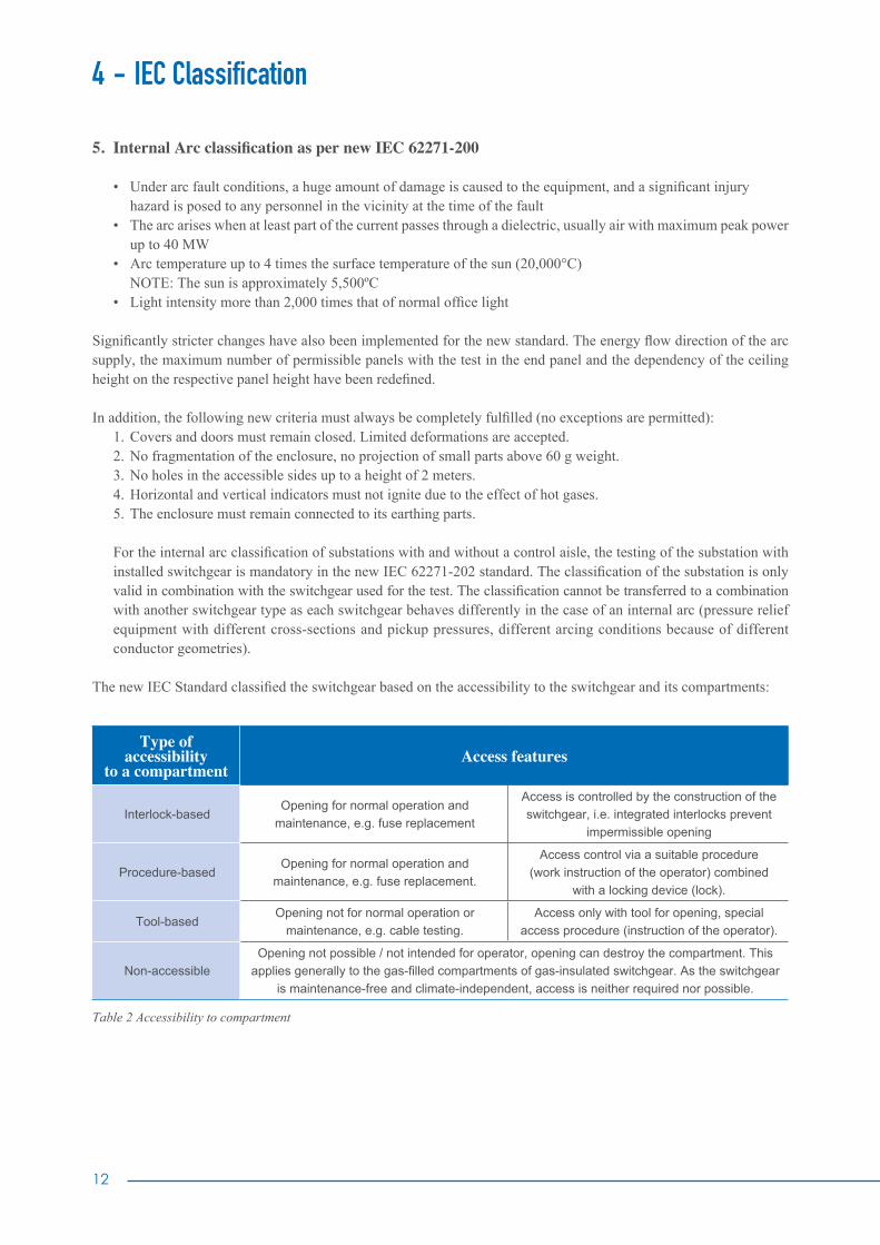
a) Singlebus–SinglebreakerThe medium voltage switchgears with a single busbar are a clear solution for your power supply with minimal space requirements. This arrangement involves one main bus with all circuits connected directly to the bus.
• Advantages: a. Cost effective b. Simple circuit c. Easy to apply differential protection d. Requires only one set of VTs to monitor the voltage of busbar
• Disadvantages: a. Low reliability, any fault will cause outage of the system b. Harder to conduct maintenance on the system c. Low flexibility
Figure 4Single bus – single breaker
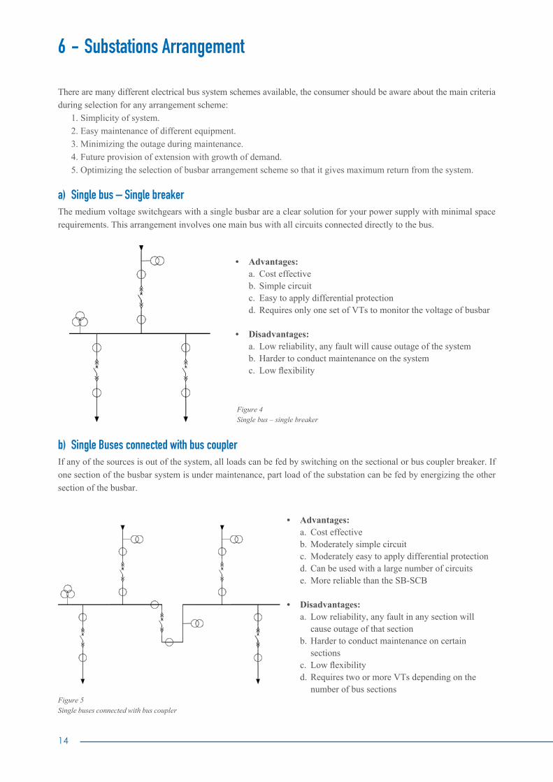
b) Single Buses connected with bus coupler If any of the sources is out of the system, all loads can be fed by switching on the sectional or bus coupler breaker. If one section of the busbar system is under maintenance, part load of the substation can be fed by energizing the other section of the busbar.
• Advantages: a. Cost effective b. Moderately simple circuit c. Moderately easy to apply differential protection d. Can be used with a large number of circuits e. More reliable than the SB-SCB
• Disadvantages: a. Low reliability, any fault in any section will cause outage of that section b. Harder to conduct maintenance on certain sections c. Low flexibility d. Requires two or more VTs depending on the number of bus sections
Figure 5Single buses connected with bus coupler

c) Ring Bus
In this scheme, as indicated by the name, all breakers are arranged in a ring with circuits tapped between breakers. For
a failure on a circuit, the two adjacent breakers will trip without affecting the rest of the system. Similarly, a single bus
failure will only affect the adjacent breakers and allow the rest of the system to remain energized. However, a breaker
failure or breakers that fail to trip will require adjacent breakers to be tripped to isolate the fault.
• Advantages:
a. High flexibility
b. High reliability
c. Cost effective compared to other high reliability systems
d. Easier maintenance on the system
e. Requires less area than above systems
• Disadvantages:
a. Requires more VTs depending on the number of lines
b. Its differential is complex and similar to line differential protection
c. The required protection system is complex
Figure 6Parallel feeder network
16
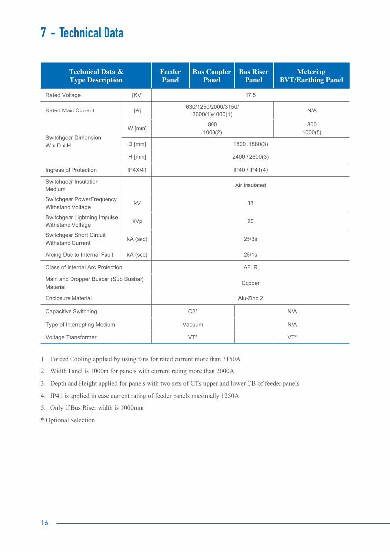
7 - Technical Data
Technical Data & Type Description
Feeder Panel
Bus CouplerPanel
Bus Riser Panel
Metering BVT/Earthing Panel
Rated Voltage [KV] 17.5
Rated Main Current [A]630/1250/2000/3150/
3600(1)/4000(1)N/A
Switchgear DimensionW x D x H
W [mm]800
1000(2)800
1000(5)
D [mm] 1800 /1880(3)
H [mm] 2400 / 2600(3)
Ingress of Protection IP4X/41 IP40 / IP41(4)
Switchgear Insulation Medium
Air Insulated
Switchgear PowerFrequency Withstand Voltage
kV 38
Switchgear Lightning Impulse Withstand Voltage
kVp 95
Switchgear Short Circuit Withstand Current
kA (sec) 25/3s
Arcing Due to Internal Fault kA (sec) 25/1s
Class of Internal Arc Protection AFLR
Main and Dropper Busbar (Sub Busbar) Material
Copper
Enclosure Material Alu-Zinc 2
Capacitive Switching C2* N/A
Type of Interrupting Medium Vacuum N/A
Voltage Transformer VT* VT*
1. Forced Cooling applied by using fans for rated current more than 3150A
2. Width Panel is 1000m for panels with current rating more than 2000A
3. Depth and Height applied for panels with two sets of CTs upper and lower CB of feeder panels
4. IP41 is applied in case current rating of feeder panels maximally 1250A
5. Only if Bus Riser width is 1000mm
* Optional Selection
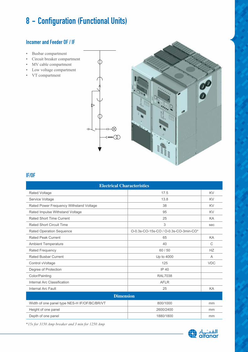
IF/OF
Electrical CharacteristicsRated Voltage 17.5 KV
Service Voltage 13.8 KV
Rated Power Frequency Withstand Voltage 38 KV
Rated Impulse Withstand Voltage 95 KV
Rated Short Time Current 25 KA
Rated Short Circuit Time 3 sec
Rated Operation Sequence O-0.3s-CO-15s-CO / O-0.3s-CO-3min-CO*
Rated Peak Current 65 KA
Ambient Temperature 40 C
Rated Frequency 60 / 50 HZ
Rated Busbar Current Up to 4000 A
Control vVoltage 125 VDC
Degree of Protection IP 40
Color/Painting RAL7038
Internal Arc Classification AFLR
Internal Arc Fault 25 KA
DimensionWidth of one panel type NES-H IF/OF/BC/BR/VT 800/1000 mm
Height of one panel 2600/2400 mm
Depth of one panel 1880/1800 mm
*15s for 3150 Amp breaker and 3 min for 1250 Amp
Incomer and Feeder OF / IF
• Busbar compartment• Circuit breaker compartment• MV cable compartment• Low voltage compartment• VT compartment
8 - Configuration (Functional Units)
18
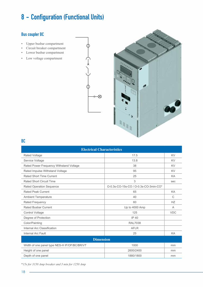
BC
Electrical CharacteristicsRated Voltage 17.5 KV
Service Voltage 13.8 KV
Rated Power Frequency Withstand Voltage 38 KV
Rated Impulse Withstand Voltage 95 KV
Rated Short Time Current 25 KA
Rated Short Circuit Time 3 sec
Rated Operation Sequence O-0.3s-CO-15s-CO / O-0.3s-CO-3min-CO*
Rated Peak Current 65 KA
Ambient Temperature 40 C
Rated Frequency 60 HZ
Rated Busbar Current Up to 4000 Amp A
Control Voltage 125 VDC
Degree of Protection IP 40
Color/Painting RAL7038
Internal Arc Classification AFLR
Internal Arc Fault 25 KA
DimensionWidth of one panel type NES-H IF/OF/BC/BR/VT 1000 mm
Height of one panel 2600/2400 mm
Depth of one panel 1880/1800 mm
*15s for 3150 Amp breaker and 3 min for 1250 Amp
8 - Configuration (Functional Units)
Bus coupler BC
• Upper busbar compartment• Circuit breaker compartment• Lower busbar compartment
• Low voltage compartment

BR
Electrical CharacteristicsRated Voltage 17.5 KV
Service Voltage 13.8 KV
Rated Power Frequency Withstand Voltage 38 KV
Rated Impulse Withstand Voltage 95 KV
Rated Short Time Current 25 KA
Rated Short Circuit Time 3 sec
Rated Operation Sequence NA
Rated Peak Current 65 KA
Ambient Temperature 40 C
Rated Frequency 60 HZ
Rated Busbar Current Up to 4000 A
Control Voltage 125 VDC
Degree of Protection IP 40
Color/Painting RAL7038
Internal Arc Classification AFLR
Internal Arc Fault 25 KA
DimensionWidth of one panel type NES-H IF/OF/BC/BR/VT 800 / 1000 mm
Height of one panel 2600/2400 mm
Depth of one panel 1880/1800 mm
Bus riser BR
• Busbar compartment• Low voltage compartment• VT compartment

20
9 - Main Components
A - Vacuum circuit breaker VCBAlthough there are still air, compressed air, bulk oil and minimum oil switches and circuit breakers in service, most of the modern switching and interpreting devices are vacuum type or SF6.
1 - Arc-quenching media
Oil allows compact installations but is outdated in MV switchgear as an insulating material for many reasons such as fire risk and its susceptibility to contamination, from moisture and by-products after switching. High maintenance requirements and costs also has a negative impact on the use of oil as an arc quenching media.
Epoxy resin has been used since the mid-1950s and is a very good insulator that can be used as a construction mate-rial. Epoxy resin consists of 80 percent pure sand and 20 percent epoxy with hardener.
Generally, epoxy resin is not aging, however a good design greatly depends on the knowledge of electrical fields. The epoxy can be shaped in such a way that those fields are minimized, resulting in low electrical stress on its’ surroundings, which can be normal air at atmospheric pressure. It is important to create smooth shapes to avoid too high electrical and mechanical stresses for the conductive parts that are embedded in epoxy insulation.
Air can be considered outdated as an arc-quenching medium due to the relatively bulky volumes needed, sound as-pects when operating, and moisture sensitivity.
Modern media: The choice is between SF6 and vacuum, each with pros and cons but both have very good arc-quench-ing properties. The discussion sometimes tends to be biased by the preferences of the SF6 manufacturer who claim the vacuum adepts to be environmentally friendly and put green logos on their switchgear. Traditional manufacturers of SF6 switchgear started vacuum developments, while vacuum switchgear manufacturers stick to vacuum.
A lot of activities have been set up to keep SF6 on the market such as ecological studies sponsored by a SF6 suppliers and SF6-switchgear manufacturers.
As a result of this push three dedicated IEC standards exist for SF6, while none exists for vacuum switchgears.
Standard YearIEC 60376 1971
IEC 60480 1974
IEC 61634* 1995
In the meantime, the European Parliament and the Council have published a draft regulationfor certain fluorinated greenhouse gases inclusive of SF6 with a legal base “Draft regulation European Parliament: 2003/0189A (COD)”.
*This publication has been replaced by IEC 62271-303:2008
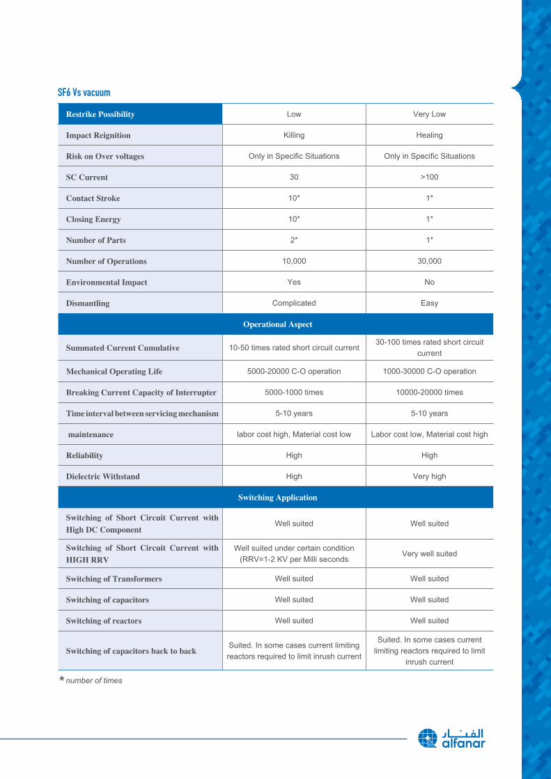
SF6 Vs vacuum
Restrike Possibility Low Very Low
Impact Reignition Killing Healing
Risk on Over voltages Only in Specific Situations Only in Specific Situations
SC Current 30 >100
Contact Stroke 10* 1*
Closing Energy 10* 1*
Number of Parts 2* 1*
Number of Operations 10,000 30,000
Environmental Impact Yes No
Dismantling Complicated Easy
Operational Aspect
Summated Current Cumulative 10-50 times rated short circuit current30-100 times rated short circuit
current
Mechanical Operating Life 5000-20000 C-O operation 1000-30000 C-O operation
Breaking Current Capacity of Interrupter 5000-1000 times 10000-20000 times
Time interval between servicing mechanism 5-10 years 5-10 years
maintenance labor cost high, Material cost low Labor cost low, Material cost high
Reliability High High
Dielectric Withstand High Very high
Switching Application
Switching of Short Circuit Current with High DC Component
Well suited Well suited
Switching of Short Circuit Current with HIGH RRV
Well suited under certain condition (RRV=1-2 KV per Milli seconds
Very well suited
Switching of Transformers Well suited Well suited
Switching of capacitors Well suited Well suited
Switching of reactors Well suited Well suited
Switching of capacitors back to backSuited. In some cases current limiting reactors required to limit inrush current
Suited. In some cases current limiting reactors required to limit
inrush current
* number of times

22
2 - Switching Devices
• Circuit-breakers (CB)connect (Make) and disconnect (break) all currents with-in their ratings limits, for all inductive and capacitive loads currents up to the full short-circuit current, and this under all fault conditions in the power supply system, such as earth faults, phase opposition…etc.
• SwitchesSwitch currents up to their rated normal current and make on existing short-circuits (up to their rated short-circuit making current).
• Disconnectors (isolators)Used for no-load closing and opening operations. Their function is to “isolate” downstream devices so they can be worked on.
• Three-position disconnectorsCombine the functions of disconnecting and earthing in one device. Three-position disconnectors are typical for gas-insulated switchgear.
• Switch-disconnectors (load-break switches)The combination of a switch and a disconnector, or a switch with isolating distance.
• ContactorsLoad breaking devices with a limited short-circuit mak-ing or breaking capacity, for high switching rates.
• Earthing switchesTo earth isolated circuits.
• Make-proof earthing switches (earthing switches with making capacity)Are used for the safe earthing of circuits, even if voltage is present, in the event that the circuit to be earthed was accidentally not isolated.
• FusesConsist of a fuse-base and a fuse-link. With the fuse-base, an isolating distance can be established when the fuse-link is pulled out in de-energized condition. The fuse-link is used for one single breaking of a short-circuit current.
• Surge arresters To discharge loads caused by lightning strikes (external overvoltages) or switching operations and earth faults (internal overvoltages). They protect the connected equipment against impermissibly high-voltages.
9 - Main Components

3 - VCB Features and Technical DataWith reliability as a fundamental goal, alfanar has simplified the NES-H switchgear design to mini-mize problems and gain trouble-free performance. Special attention is given to material quality and the use of components with years of proven reliability in alfanar’s switchgear.
Susol VCB are user-friendly, more convenient, safer and provide high speed interrupting time (3cycles), adopting the rapid auto-reclosing method, and have a wide range of accessories.
a. High reliability of the operating mechanism • Separate design of the main circuit from the operating mechanism • Adopt the toggle link method • Improve the reliability of electric circuit • Adopt the rapid auto-reclosing method as a standard option (O-0.3sec.-CO-3min.-CO)
b. High interrupting performance • Shortened interrupting time (3cycles) • Increased rated short-circuit withstand characteristics (1sec. to 3sec.)
c. Great operational safety • Reinforced insulation in the conduct, by adopting the molded housing in each phase • Built-in device that makes the contacts open first when drawn in and out • Adopt the tulip-shape connection between the cradle busbar and the VCB
For many decades, customers were faced with the challenge of finding a reliable VCB. alfanar provide this VCB to solve this issue for its customers.
The Susol has a wide range of optional accessories available.
• Key lock • Preparatory trip coil (Secondary trip coil)• Padlock of earthing switch • MOC (Mechanically operated cell switch)• Button padlock • Latch checking switch• Position switch of the earthing switch • TOC (Truck operated cell switch)• Button cover • Charge indicator• Locking coil of earthing switch • Code plate (Miss insertion prevention)• Position switch (Cell switch) • Position padlock• Shutter padlock • Capacitor trip device
• Rectifier
d. Great operational safety • Small size and light weight • High performance, reliability, and long life are assured • Maintains high vacuum • High-alumina ceramics provide superior mechanical strength and easy degassing • High speed interruption and short arcing time • The LS Vacuum Interrupter meets all IEC, ANSI and NEMA performance standards
24
e. Operating characteristics
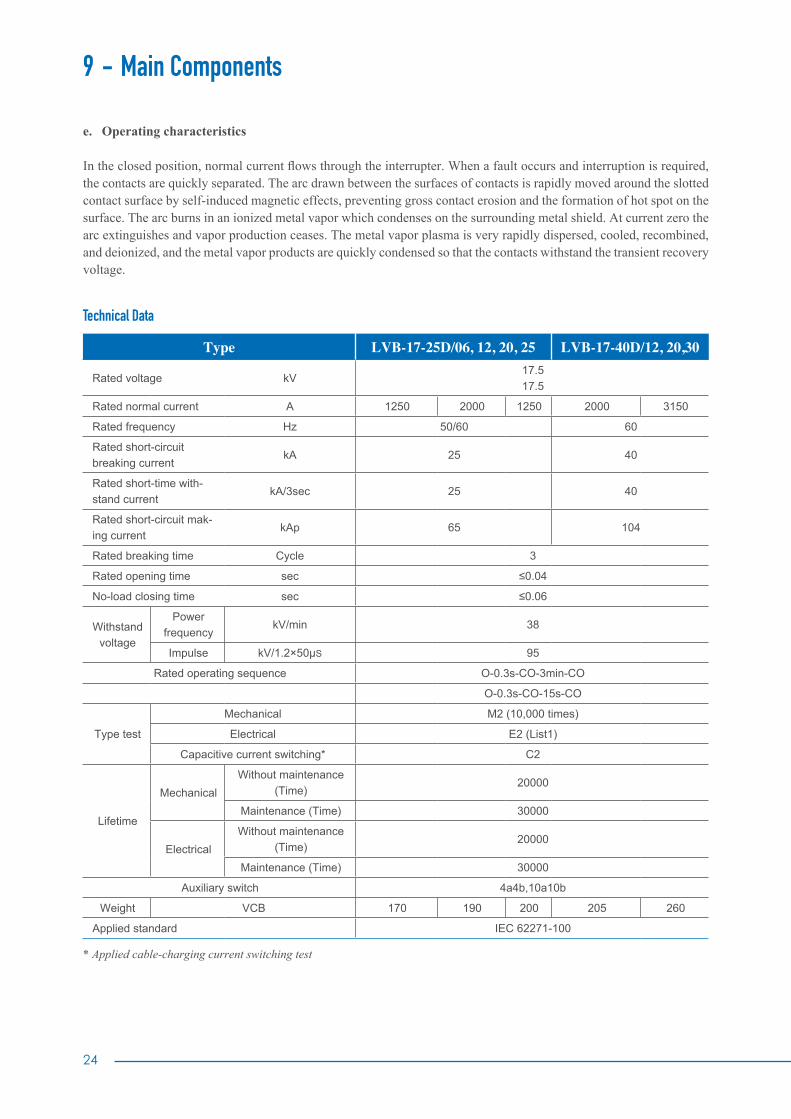
In the closed position, normal current flows through the interrupter. When a fault occurs and interruption is required, the contacts are quickly separated. The arc drawn between the surfaces of contacts is rapidly moved around the slotted contact surface by self-induced magnetic effects, preventing gross contact erosion and the formation of hot spot on the surface. The arc burns in an ionized metal vapor which condenses on the surrounding metal shield. At current zero the arc extinguishes and vapor production ceases. The metal vapor plasma is very rapidly dispersed, cooled, recombined, and deionized, and the metal vapor products are quickly condensed so that the contacts withstand the transient recovery voltage.
Technical Data
Type LVB-17-25D/06,12,20,25 LVB-17-40D/12,20,30
Rated voltage kV17.517.5
Rated normal current A 1250 2000 1250 2000 3150
Rated frequency Hz 50/60 60
Rated short-circuit breaking current
kA 25 40
Rated short-time with-stand current
kA/3sec 25 40
Rated short-circuit mak-ing current
kAp 65 104
Rated breaking time Cycle 3
Rated opening time sec ≤0.04
No-load closing time sec ≤0.06
Withstandvoltage
Power frequency
kV/min 38
Impulse kV/1.2×50µS 95
Rated operating sequence O-0.3s-CO-3min-CO
O-0.3s-CO-15s-CO
Type test
Mechanical M2 (10,000 times)
Electrical E2 (List1)
Capacitive current switching* C2
Lifetime
MechanicalWithout maintenance
(Time)20000
Maintenance (Time) 30000
ElectricalWithout maintenance
(Time)20000
Maintenance (Time) 30000
Auxiliary switch 4a4b,10a10b
Weight VCB 170 190 200 205 260
Applied standard IEC 62271-100
* Applied cable-charging current switching test
9 - Main Components

MotorWhen the closing spring is charged, the control power of motor is turned off by the built-in limit s/w.
Rated voltageThe peak value of the inrush current
(A)Rated current (A) Consumption
power (W)Charging time
(Sec.)
DC 48V 21 4 350 13
DC 110V 20 3 330 12
DC 125V 20 3 330 12
DC 220V 17 2.6 374 12
Note 1) Range of the normal operating voltage: 85~110%2) DC 24V is the underdeveloped rating
Closing Coil (C)The coil is operational only when the power is applied continuously over 45ms. It has a built-in electrically anti-pumping circuit.
Rated voltage Rated current (A)DC 48V 6
DC 110V 3
DC 125V 3
DC 220V 2.5
Shunt Coil (TC)When the VCB is ‘ON’ position, even though the control power of a shunt coil is ‘OFF’, the VCB maintains the ‘ON’ position.
Rated voltage Rated current (A)DC 48V 6
DC 110V 3
DC 125V 3
DC 220V 2.5
Note 1) Range of the normal operating voltage: 85~110%2) DC 24V is the underdeveloped rating.
Note 1) Range of the normal operating voltage: 70~110%2) DC 24V is the underdeveloped rating.

26
Auxiliary SwitchStandard 4a4b / Optional 10a10b
Classification General load (A)
Inductive load (A)
Contactconfiguration
Contact Ratings
AC250V 10 5
4a4b10a10b
125V 10 5
DC
250V 10 5
125V 10 5
30V 10 5
Note The contact capacity of the following accessories are the same as that of the Aux. switch. Position switch, Closing spring contact, Charging complete indicating contact, Position switch of the earthing switch, Mechanically operated cell switch, Truck operated cell switch.
Position of the Aux.contact switch
Classification
VCB “a” contact “b”contact
ON ON OFF
OFF OFF ON
Note The contact capacity of the following accessories are the same as that of the Aux. switch. Position switch, Closing spring contact, Charging complete indicating contact, Position switch of the earthing switch, Mechanically operated cell switch, Truck operated cell switch.
9 - Main Components
B - Instrument Transformers IT
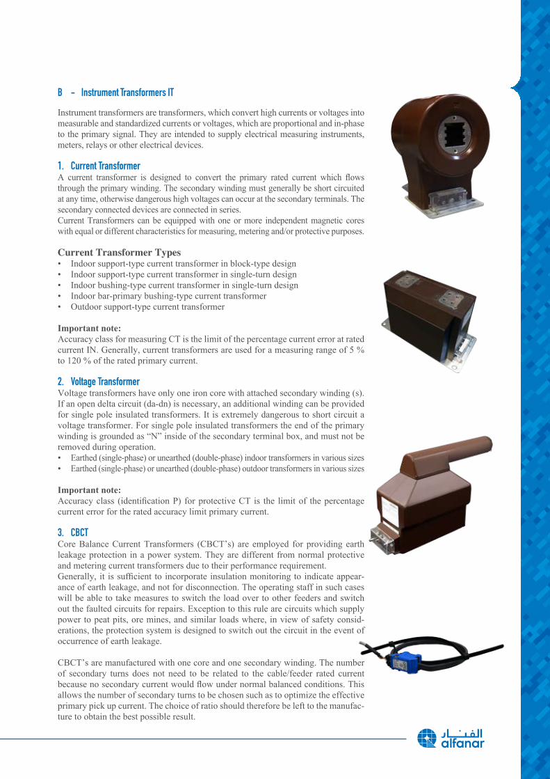
Instrument transformers are transformers, which convert high currents or voltages into measurable and standardized currents or voltages, which are proportional and in-phase to the primary signal. They are intended to supply electrical measuring instruments, meters, relays or other electrical devices.
1. Current Transformer A current transformer is designed to convert the primary rated current which flows through the primary winding. The secondary winding must generally be short circuited at any time, otherwise dangerous high voltages can occur at the secondary terminals. The secondary connected devices are connected in series. Current Transformers can be equipped with one or more independent magnetic cores with equal or different characteristics for measuring, metering and/or protective purposes.
Current Transformer Types• Indoor support-type current transformer in block-type design• Indoor support-type current transformer in single-turn design • Indoor bushing-type current transformer in single-turn design • Indoor bar-primary bushing-type current transformer • Outdoor support-type current transformer
Important note: Accuracy class for measuring CT is the limit of the percentage current error at rated current IN. Generally, current transformers are used for a measuring range of 5 % to 120 % of the rated primary current.
2. Voltage TransformerVoltage transformers have only one iron core with attached secondary winding (s). If an open delta circuit (da-dn) is necessary, an additional winding can be provided for single pole insulated transformers. It is extremely dangerous to short circuit a voltage transformer. For single pole insulated transformers the end of the primary winding is grounded as “N” inside of the secondary terminal box, and must not be removed during operation.• Earthed (single-phase) or unearthed (double-phase) indoor transformers in various sizes• Earthed (single-phase) or unearthed (double-phase) outdoor transformers in various sizes
Important note: Accuracy class (identification P) for protective CT is the limit of the percentage current error for the rated accuracy limit primary current.
3. CBCTCore Balance Current Transformers (CBCT’s) are employed for providing earth leakage protection in a power system. They are different from normal protective and metering current transformers due to their performance requirement.Generally, it is sufficient to incorporate insulation monitoring to indicate appear-ance of earth leakage, and not for disconnection. The operating staff in such cases will be able to take measures to switch the load over to other feeders and switch out the faulted circuits for repairs. Exception to this rule are circuits which supply power to peat pits, ore mines, and similar loads where, in view of safety consid-erations, the protection system is designed to switch out the circuit in the event of occurrence of earth leakage.
CBCT’s are manufactured with one core and one secondary winding. The number of secondary turns does not need to be related to the cable/feeder rated current because no secondary current would flow under normal balanced conditions. This allows the number of secondary turns to be chosen such as to optimize the effective primary pick up current. The choice of ratio should therefore be left to the manufac-ture to obtain the best possible result.
28
C - Power System Protection
1 - Protection Relays
a - Basic Requirements of Protection Systems The protection system is an extremely important part of the power system as it will operate under abnormal conditions to prevent failure or isolate faults and limits the effects of the faults. Some basic requirements of the protection system are to provide reliability, selectivity, sensitivity and speed of opera-tion.
• Reliability Reliability is the basic requirement of the protection system. The protection system must be ready to function correctly at all the times and under all conditions of the fault and abnormal conditions of the whole power system for which the protection system is designed.
• Selectivity Selectivity is the ability of the protective system to correctly select the part of the system in trouble and disconnect and isolate the faulty part without disturbing the rest of the power system.A well designed and efficient protective system should be selective i.e, it should be able to detect the point at which the fault occurs and operate the circuit breaker nearest to the fault with minimum or no damage to the system.
• Sensitivity A protective system must be sufficiently sensitive so that it will operate reliably when required under the actual con-dition that produces the least operating tendency. Sensitivity of the protective system refers to the smallest value of the actuating quantity at which the protective system starts operating in relation with the maximum value of the fault current in the protected zone.
• Speed The protective system should disconnect the faulty section as quick as possible. This is desirable to reduce damage, improve power system stability, minimize power supply interruption to consumers. However, too fast of an operation may result in undesired operation during the transient faults.
• Simplicity The protection system should be simply constructed with a good quality of relay, correct design and installation, easy maintenance and operational supervision. As a rule of thumb, the simpler the protective scheme and lesser the number of relays, circuits and contacts it contains, the greater the reliability.
A Power System consists of various electrical components like a generator, transformers, transmission lines, isola-tors, circuit breakers, busbars, cables, relays, instrument transformers, distribution feeders, and various types of loads. Faults may occur in any part of power system as a short circuit and earth fault. A fault may be single line to ground, double line to ground, line to line, three phase short circuit etc. This results in flow of heavy fault current through the system. Fault level also depends on the fault impedance which depends on the location of fault referred from the source side. To calculate fault level at various points in the power system, fault analysis is necessary.
The protection system operates and isolates the faulty section. The operation of the protection system should be fast and selective i.e. it should isolate only the faulty section in the shortest possible time causing minimum disturbance to the system. Also, if main protection fails to operate, there should be a backup protection for which proper relay co-ordi-nation is necessary. Failure of a protective relay can result in devastating equipment damage and prolonged downtime.
9 - Main Components

b - RelaysRelays are electrically operated power-switching devices, that do not operate until directed by some external device to open or close. Sensors and relays are used to detect the overcurrent or other abnormal or unacceptable condition and to signal the switching mechanism to operate. The MV circuit breakers are the brute-force switches while the sensors and relays are the brains that direct their functioning.
In switchgear application, the most common sensors are CTs to measure current and PTs to measure voltage. The relays measure sensor output and cause the breaker to operate to protect the system when preset limits are exceeded, hence the name “protective relays.” The availability of a variety of sensors, relays, and circuit breakers permits the design of complete protection systems as simple or as complex as necessary, desirable, and economically feasible.
In most cases of direct feeding from (National Grid), the MV switchgear should be chosen very carefully, specially the relays where the major requirement of SEC is to select the relay matching the upper stream in order to apply a dif-ferential protection on the busbar, line and incomers. Therefore, an advantage of using alfanar relays is the flexibility of choosing the protection relay based on the situation and load.
Types of Relays
In MV switchgear application, a number of relays can be installed in every single cubical, and each relay has a spe-cific function and assigned task, for example: one relay may be responsible for tripping the breaker while the other is responsible for supervision or monitoring.Listed below are types of relays that are used in MV switchgear assemblies:
1 - Protective Relays
A protective relay is designed to trip when a fault is detected .Protective relays work in concert with sensing and control devices to accomplish their function. Under normal power system operation, a protective relay remains idle and serves no active function. But when fault or undesirable condi-tions arises the protective relay must be operated and function correctly to disconnect a faulty section.
Examples of protective relays:
• Overcurrent Relay
This relay detects current above normal settings and operates when the current increases beyond the operating value of the relay. Depending upon the time of operation, overcurrent relays can be categorized as instantaneous overcur-rent relay, inverse time overcurrent relay, definite time overcurrent relay, inverse definite time overcurrent relay, very inverse overcurrent relay and extremely inverse overcurrent relay.
• Directional Overcurrent Relay
This relay responds to excessive current flow in a particular direction in the power system. The relay typically consists of two elements. One is a directional element, which determines the direction of current flow with respect to a voltage reference. When this current flow is in the predetermined trip direction, this directional element enables (“turns on”) the other element, which is a standard overcurrent relay. Because these relays are designed to operate on fault currents, the directional unit is made so that it operates best on a highly lagging current, which is typical of faults in power systems.
Directional overcurrent relays are normally used on incoming line circuit breakers on buses which have two or more sources. They are connected to trip an incoming line breaker for fault current flow back into the source, so that a fault on one source is not fed by the other sources.
30
• Differential Relay
A differential relay is defined as the relay that operates when the difference of two or more identical electrical quanti-ties exceeds a predetermined amount. The differential relay works on the principle of comparison of two or more simi-lar electrical quantities. For example, consider the comparison of the current entering a protected line and the current leaving it. If the current enters the protected line is more than the current leaving it, then the extra current must flow in the fault. The difference between the two electrical quantities can operate a relay to isolate the circuit.The differential protection principle is widely employed for the protection of generators, transformers, feeders, and busbars.
2 - Auxiliary Relays
Auxiliary relays operate in response to opening and closing of its operating circuit to assist another relay or device in performance of a function. For example, a measuring relay, for the purpose of providing higher rated contacts or introducing a time delay.The auxiliary relays are used for all kinds of control and protection circuits in power stations and industrial installa-tions, where a high degree of reliability and a high contact rating are stipulated, with minimal internal consumption. Acting as an instantaneous switching element, it provides galvanic separation and contact multiplication in tripping and signaling circuits of protective relays.
Examples of auxiliary relays in MV Switchgear assemblies:
• Tripping Relays
1) Self-Reset Relay
The self-reset relay is a high speed trip auxiliary relay. When the fault occurs, the coil is energized and the contact oper-ates to trip the circuit breaker. The self-reset relay is used where auto reclosing is required to close the circuit breaker whenever a temporary fault occurs.
2) Lockout Relays
The lockout relay is a high speed trip auxiliary relay, a lockout means once the coil is energized the contact will be operated and will never come to normal position until it is reset by hand or electrically. Therefore, it is used by many utilities in electrical power transmission substations to trip and hold out of service a protection zone on the occurrence of a relay operation that requires inspection and/or repair before the zone may be safely placed back in service. Lockout relays ensure that all the critical circuits are isolated and remain isolated as long as the fault is not cleared.
9 - Main Components
• Monitoring Relays
1) DC Supervision Relay This type of relay is used to supervise the DC supply for all MV switchgear functional units. The relay coil terminals are connected to the DC supply which is to be monitored. In case the DC auxiliary supply is available, the relay’s ‘NO’ contact closes and healthy status is indicated through a ‘WHITE’ flag. In the absence of the DC auxiliary supply, an alarm signal is generated and a ‘RED’ flag is indicated .
2) Trip Circuit Supervision Relay This supervision relay is designed for the supervision of trip circuits and other important control and monitoring cir-cuits. For example, in a protection system the trip circuit of the circuit breaker is crucial, if an interruption occurs in the trip circuit a possible network fault will not be disconnected and would have to be cleared by another protection upstream in the power system. The trip circuit supervision relay is intended for a continuous supervision of circuit breaker’s trip circuit and to give an alarm for loss of auxiliary supply, faults on the trip-coil or its wires independent of the breaker position, faults on the breaker auxiliary contacts and faults in the supervision relay itself.
3) VT Fuse Supervision Relay The voltage transformer supervision feature is used to detect failure of the AC voltage inputs to the relay. This may be caused by internal voltage transformer faults, overloading, or faults on the interconnecting wiring to relays. This usually results in one or more VT fuses blowing. Following a failure of the AC voltage input there would be a mis-representation of the phase voltages on the power system as measured by the relay, which may result in malfunction.
4) CT Circuit Supervision RelayThe current transformer supervision feature is used to detect failure of one or more of the AC phase current inputs to the relay. Failure of a phase CT or an open circuit of the interconnecting wiring can result in incorrect operation of any current operated element. Additionally, interruption in the AC current circuits risks dangerous CT secondary voltages being generated.
• Contacts Multiplication Relays Contacts multiplication relays are used to get extra ‘NO’ and ‘NC’ contacts that can be used somewhere else as a status indication, interlocks and other switching operations.
D - High Speed Earthing Switch
IEC air-insulated switch disconnectors are suitable for cable sectionalizer, transformer, motor and capacitor bank switching, in secondary distribution substations for supplying lines, transformers and ring networks. Earthing switch is used to connect the cables or busbar to the earth for safety during maintenance and otherworks to be executed on the switchgear. It has a fast acting mechanism independent to the operator,interlocking provision and voltage capacitive divider insulators. The switch has a making capacity and it complies with the applicable IEC standard.
The task of an earthing switch is to earth de-energised parts of the switchgear and, in the case of multi-pole earthing switches,to short-circuit them at the same time.
32
NES-H switchgear has undergone all the tests required by the international (IEC) Standards and localStandards organizations.In addition, tests were carried out on switchgear units considered most sensitive to the effects of the tests and therefore the results were extended across the whole range.
Each switchgear unit is subjected to routine tests in the factory before delivery.
These tests are intended to provide a functional check of the switchgear based on the specific characteristics ofeach installation.
IEC type tests
• Short-time and peak withstand current• Temperature rise• Internal arc capability• Dielectric test• Making and breaking capacity of circuit-breaker and contactors• Earthing switch making capacity• Mechanical operations of circuit-breaker and earthing switch• IP protection degree
10 - Type Test
Description of IEC type tests
• Short-time and peak withstand currentThe test shows that the main power and the earthing circuits resist the stresses caused by the passage of the short-circuit current without any damage. Both the earthing system of the withdrawable circuit-breaker and the earthing busbar of the switchgear are subjected to the test.The mechanical and electrical properties of the main busbar system and the top and bottom branch connections remain unchanged even in the case of a short-circuit.
• Temperature riseThe temperature rise test is carried out at the rated current value of the switchgear unit and showing that the tempera-ture does not become excessive in any part of the switchgear unit. During the test, both the switchgear and the circuit-breaker or contactor it may be fitted with are checked.
• Internal arc capabilityInternal arc testing verifies the potential risk to a person standing within a few feet of switchgear during an arc flash. To this end, the test is carried out in a simulated room with indicators that mimic human skin to assess the danger of burns from escaping hot gases. According to the latest standard – IEC 62271-200 (2003) – the position and arrangement of these indicators is determined by who will be able to access the switchgear in use. This test replicates the effect of protective clothing that will be worn by authorized personnel but not by the general public.
• Dielectric testThese tests verify that the switchgear has sufficient capability to withstand the lightning impulse and the power fre-quency voltage. The power frequency withstand voltage test is carried out as a type test, but it is also a routine test on every switchgear unit manufactured.
• Circuit-breaker making and breaking capacityThe circuit-breaker or contactor is subjected to the rated current and short-circuit current breaking tests.It is also subjected to the opening and closing of capacitive and inductive loads, capacitor banks and/or cable lines.
• Earthing switch making capacityThe earthing switch of the NES-H switchgear can be closed under short-circuit. The earthing switch isnormally interlocked to avoid being operated on circuits which are still live, however, should this occur, personnel safety would be fully safeguarded.
• Mechanical operationsThe mechanical endurance tests conducted on all the operating parts ensures the reliability of the apparatus. General experience in the electro-technical sector shows that mechanical faults are one of the most common causes of a fault in an installation. The circuit-breaker is tested by carrying out a higher number of operations than those which are normally carried out by installations in the field. Furthermore, the switchgear components are part of a quality control program and samples are regularly taken from the production lines and subjected to mechanical life tests to verify that the quality is identical to that of the components subjected to the type tests.
• IP protection degreeThe IP protection degree is the resistance offered by the NES-H against penetration of solid objects and liquids.This degree of resistance is indicated by the prefix IP followedby two characters (i.e. IP4X), where the first number identifies the degree of protection against theentrance of solid objects, and the second one is related to liquids.
34
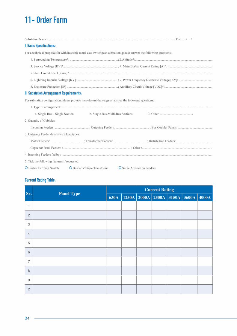
11- Order Form
Substation Name: ............................................................................................................................................................. ; Date: / /
I. Basic Specifications:
For a technical proposal for withdrawable metal clad switchgear substation, please answer the following questions:
1. Surrounding Temperature*: ............................................................ ; 2. Altitude*:.................................................................................................
3. Service Voltage [KV]*:................................................................... ; 4. Main Busbar Current Rating [A]*: ........................................................
5. Short Circuit Level [KA/s]*: ..................................................................................................................................................................................
6. Lightning Impulse Voltage [KV]: .................................................. ; 7. Power Frequency Dielectric Voltage [KV]: ..........................................
8. Enclosure Protection [IP] ................................................................ ; Auxiliary Circuit Voltage [VDC]*: ...........................................................
II. Substation Arrangement Requirements:
For substation configuration, please provide the relevant drawings or answer the following questions:
1. Type of arrangement: .............................................................................................................................................................................................
a. Single Bus – Single Section b. Single Bus-Multi-Bus Sections C. Other:..........................................
2. Quantity of Cubicles:
Incoming Feeders: .......................................... ; Outgoing Feeders: .......................................... ; Bus Coupler Panels :..........................................
3. Outgoing Feeder details with load types:
Motor Feeders:.......................................... ; Transformer Feeders:.......................................... ; Distribution Feeders:..............................................
Capacitor Bank Feeders :......................................................................................; Other :........................................................................................
4. Incoming Feeders fed by : .............................................................................................................................................................................................
5. Tick the following features if requested:
Busbar Earthing Switch Busbar Voltage Transforme Surge Arrester on Feeders
Current Rating Table:
Sr. Panel TypeCurrent Rating
630A 1250A 2000A 2500A 3150A 3600A 4000A
1
2
3
4
5
6
7
8
9
2

Current Rating Table:
Sr. Panel Type ANSI Protection Functions Others
1 50/51 50N/51N 59/27 49 32 46 67 81 25 79 50BF VTFF 86 87
2 50/51 50N/51N 59/27 49 32 46 67 81 25 79 50BF VTFF 86 87
3 50/51 50N/51N 59/27 49 32 46 67 81 25 79 50BF VTFF 86 87
4 50/51 50N/51N 59/27 49 32 46 67 81 25 79 50BF VTFF 86 87
5 50/51 50N/51N 59/27 49 32 46 67 81 25 79 50BF VTFF 86 87
6 50/51 50N/51N 59/27 49 32 46 67 81 25 79 50BF VTFF 86 87
7 50/51 50N/51N 59/27 49 32 46 67 81 25 79 50BF VTFF 86 87
8 50/51 50N/51N 59/27 49 32 46 67 81 25 79 50BF VTFF 86 87
9 50/51 50N/51N 59/27 49 32 46 67 81 25 79 50BF VTFF 86 87
10 50/51 50N/51N 59/27 49 32 46 67 81 25 79 50BF VTFF 86 87
• Communication Protocol, if applicable*: ....................................................................................................................................................................
CT Details:
Please provide load details on each feeder to calculate CT parameters; otherwise please specify CT ratio and class in the following table
CT Panel Type
CT Details
Core1 Core2 Core3
Ratio Class Burden Ratio Class Burden Ratio Class Burden
CT1
CT2
CT3
CT4
CT5
CT6
CT7
CT8
CT9
CT10
CT11
IV: Special Requirements:
...........................................................................................................................................................................................................................................
...........................................................................................................................................................................................................................................
...........................................................................................................................................................................................................................................
...........................................................................................................................................................................................................................................

36
www.alfanar.com
MKT_99056_MVS_Feb18_01For catalogue soft copy scan QR code