medium voltage switchgear - sgc - switchgear … user ma… · 4 dr-6c medium voltage switchgear...
TRANSCRIPT
DW
6453
14
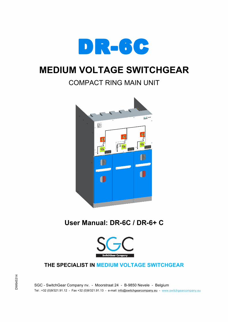
DR-6C
MEDIUM VOLTAGE SWITCHGEAR
COMPACT RING MAIN UNIT
User Manual: DR-6C / DR-6+ C
THE SPECIALIST IN MEDIUM VOLTAGE SWITCHGEAR SGC - SwitchGear Company nv. - Moorstraat 24 - B-9850 Nevele - Belgium
Tel : +32 (0)9/321.91.12 - Fax +32 (0)9/321.91.13 - e-mail: [email protected] - www.switchgearcompany.eu
ii User Manual – DR-6C/DR-6+C DW645314
© 2013 SGC – SwitchGear Company nv. All rights reserved. The information provided herein may not be reproduced and/or (re)published in any way and by any means (electronic or mechanical), without the prior, explicit written authorization of SGC - SwitchGear Company nv. The information provided herein is based on general data concerning the construction, known at the time of publication, and concerning the qualities of the material and working methods. Consequently, the right to make changes is reserved. The information contained within is applicable to the standard version of the DR-6 medium-voltage switchgear. Therefore, SGC - SwitchGear Company nv cannot be held liable for any damage resulting from specifications that differ from the standard version of the DR-6 medium-voltage switchgear. The available information has been assembled with the greatest possible care, but SGC - SwitchGear Company nv cannot be held liable for any mistakes in the information, or the consequences thereof. The user names, trade names, trademarks, etc., used by SGC - SwitchGear Company nv cannot, in accordance with the legislation concerning the protection of trademarks, considered to be free.
iv User Manual – DR-6C/DR-6+C DW645314
CONTENTS
CONTENTS .................................................................................................... iv PREFACE ...................................................................................................... vi
About this manual ...................................................................................................................... vi Pictograms and safety symbols in and on the medium voltage switchgear .............................. vi Pictograms in the documentation ............................................................................................. vii Related documentation ............................................................................................................. vii Service and technical support .................................................................................................. viii General safety directions and instructions ................................................................................ viii Intended use .............................................................................................................................. ix
1 GENERAL INSTALLATION & SAFETY INSTRUCTIONS .................... 1-1 1.1.1 General .................................................................................................................. 1-1 1.1.2 Recommendations – installation room .................................................................. 1-1 1.1.2.1 Floor surface .......................................................................................................... 1-1 1.1.2.2 Environmental conditions ...................................................................................... 1-2 1.1.2.3 Ventilation .............................................................................................................. 1-2 1.1.2.4 Free height of the installation area ........................................................................ 1-3 1.1.2.5 Sizes of the entrance doors to the installation area ............................................... 1-3 1.1.2.6 Free passage in front of the cubicles ..................................................................... 1-3 1.1.2.7 Internal arc protection ............................................................................................ 1-4
2 USE ......................................................................................................... 2-1 2.1 Safety instructions – use ....................................................................................... 2-1 2.2 Identification of the cubicles .................................................................................. 2-1 2.2.1 Type plate .............................................................................................................. 2-1 2.2.2 Serial number ........................................................................................................ 2-2 2.3 Operation ............................................................................................................... 2-2 2.3.1 Operating the combination load break switch – earthing switch ............................ 2-3 2.3.1.1 Opening the load break switch and closing the earthing switch ............................ 2-3 2.3.1.2 Opening the earthing switch and closing the load break switch ............................ 2-4 2.3.2 Reading the capacitive voltage indicators ............................................................. 2-4 2.3.3 Operating the combination load break switch – fuse ............................................. 2-5 2.3.3.1 Opening the load break switch and closing the earthing switch ............................ 2-5 2.3.3.2 Opening the earthing switch and closing the load break switch ............................ 2-6 2.3.4 2-6 2.4 Interlocks ............................................................................................................... 2-7 2.4.1 Interlocks between load break switch and earthing switch .................................... 2-7 2.4.2 Door interlock ........................................................................................................ 2-7 2.4.2.1 Accessing the cable compartment ......................................................................... 2-7 2.4.2.2 Refitting the door ................................................................................................... 2-7 2.5 Measuring the phase sequence ............................................................................ 2-8 2.6 Disassembly of the front panel .............................................................................. 2-8
DW645314 User Manual – DR-6C/DR-6+C v
3 MAINTENANCE ...................................................................................... 3-1 3.1 Safety guidelines - maintenance ........................................................................... 3-1 3.2 Maintenance – general .......................................................................................... 3-1 3.2.1 General control operations .................................................................................... 3-2 3.2.1.1 Cleaning DR-6C cubicles ...................................................................................... 3-2 3.2.1.2 Cleaning the exterior ............................................................................................. 3-2 3.2.1.3 Condensation ........................................................................................................ 3-2 3.2.1.4 Cleaning the interior .............................................................................................. 3-3 3.2.2 Switching the switches .......................................................................................... 3-3 3.2.3 Replacing the fuse protectors (T-function) ............................................................ 3-4 3.3 Unpacking .............................................................................................................. 3-6
4 DR-6C CUBICLES AND THE ENVIRONMENT ..................................... 4-1 4.1 Packing materials .................................................................................................. 4-1 4.2 Disposal of the cubicles ......................................................................................... 4-1 4.3 Recuperation of SF6 gas ....................................................................................... 4-1
vi User Manual – DR-6C/DR-6+C DW645314
PREFACE
About this manual This document is intended as a reference for qualified and trained operators to operate the medium voltage switchgear in a safe and economical way. This document uses the term “medium voltage switchgear” to denote a random, but in actual practice, existing combination of DR6 functions that, mutually coupled and connected, constitute a client-specific transformation or distribution station. See: “General description”. The chapters and sections are numbered. The page numbers (consisting of the chapter number and the page number) and the document code can be found at the bottom of every page. In the documentation the words “left”, “right”, “front” and “behind” are used to indicate a specific part of the medium voltage switchgear. The starting point is always the position of the operator, standing in front of the medium voltage switchgear, facing the switchgear.
Pictograms and safety symbols in and on the medium voltage switchgear Depending on the version, the following pictograms are used on the medium voltage switchgear:
WARNING Danger of high Voltage Access to this cubicle is only allowed after this cubicle and both the directly adjacent cubicles (previous and next one) are de-energized.
WARNING Drilling prohibited. Drilling is strictly prohibited on surfaces bearing this pictogram.
DW645314 User Manual – DR-6C/DR-6+C vii
Pictograms in the documentation The following pictograms apply to the medium voltage switchgear user documents:
CAUTION! A procedure that can, if not carried out with the proper care, result in damage to the medium voltage switchgear, the surrounding area or the environment.
WARNING Danger of high Voltage
CAUTION! Clamping danger Notes, suggestions and advice.
Render this cubicle, the next one and the previous cubicle, voltage-free, before carrying out the work described.
Open the load break switch and the earthing switch before carrying out the work described in the manual.
Consult the indicated information sources first. Protect the medium voltage switchgear from water and damp.
Related documentation The following technical documentation for medium voltage switchgear is available:
• Transport manual DR-6C/DR-6+C • Installation manual DR-6C/DR-6+C
viii User Manual – DR-6C/DR-6+C DW645314
Service and technical support For information concerning specific settings, maintenance or repair work which are not covered in the manual, please contact SGC - SwitchGear Company nv. • When contacting SGC - SwitchGear Company nv, always provide the following
information: − Cubicle designation and characteristics − Serial number of the cubicles
General safety directions and instructions SGC - SwitchGear Company nv does not accept any liability for damage or injury caused by not (strictly) following the safety directions and instructions, or by negligence during the installation, use, maintenance, or the repair of the medium voltage switchgear and its (possibly) accompanying options. Depending on any specific user circumstances, or installed options, extra safety instructions may be required. Please contact SGC - SwitchGear Company nv immediately if you encounter a potential danger during the operation of the medium voltage switchgear. The owner/operator of the medium voltage switchgear is fully responsible at all times for following the locally applicable safety directions and guidelines. User manual • Anyone who uses or operates the medium voltage switchgear, must be familiar with
the contents of the user manual, and follow the directions contained within very closely. The owner/operator must educate the users in accordance with the user manual and obey all directions and instructions.
• Never change the order of the required actions. • Always keep the user manual in the vicinity of the medium voltage switchgear. Pictograms and safety symbols The pictograms, symbols and instructions applied to the medium voltage switchgear are a part of the safety equipment. They may therefore not be covered or removed, and must be present and clearly readable throughout the entire lifespan of the medium voltage switchgear. • Replace or repair unreadable or damaged pictograms, symbols and instruction
immediately. Therefore contact SGC - SwitchGear Company nv. Operators The execution of the work described (transport, installation, use and maintenance) is strictly reserved for trained and qualified operators, who are familiar with the dangers that can occur when operating medium voltage switchgears. Temporary staff and personnel in training may not operate the medium voltage switchgear under any circumstances. Technical specifications • Technical specifications may not be changed. • Modification of the medium voltage switchgear (or parts thereof) is not permitted.
DW645314 User Manual – DR-6C/DR-6+C ix
Transport, storage, installation, operation and maintenance • See corresponding documents:
− “Safety guidelines – transport” − “Safety guidelines – storage” − “Safety guidelines – installation” − “Safety guidelines – operation” − “Safety guidelines – maintenance”
Intended use The medium voltage switchgear is designed exclusively for use as transformation or distribution stations, in accordance to the specifications and conditions provided by SGC - SwitchGear Company nv. Any other or further use is not in accordance with the intended use.1 SGC - SwitchGear Company nv does not accept any liability for damage(s) or injuries resulting from deviation(s) of the intended use. The medium voltage switchgear complies with the current norms and guidelines. See: Technical Brochure • Only use the medium voltage switchgear in technically perfect condition, in accordance
with the intended use described above.
Leave the sealed connections intact, at all times. Breaking the sealed connections irrevocably voids any guarantee claims.
1 The “Intended use” as defined in EN 292-1 “is the use for which the technical product is suited as specified by the manufacturer including his directions in the sales brochure.” In case of doubt, it is the use that can be deduced from the construction, the model and the function of the technical product that is considered normal use. Operating the product within the limits of its intended use also involves observing the instructions in the user manual.
DW645314 User Manual – DR-6C/DR-6+C 1-1
1 GENERAL INSTALLATION & SAFETY INSTRUCTIONS
1.1.1 General Installation of the medium voltage switchgear is restricted to qualified and trained operators with strictly observance of the locally applicable safety instructions and guidelines. The connection and commissioning must be done by qualified and authorized staff employed by the power supplying company.
• See also: "General safety prescriptions and instructions". • Never leave tools or other material in, or on top of the medium voltage switchgear. • Install the medium voltage switchgear exclusively in spaces that fully comply with the
following recommendations (according to IEC 62271-200):
1.1.2 Recommendations – installation room Recommendations regarding the installation room parameters are subdivided in recommendations concerning:
• floor surface • environmental conditions • ventilation • free height of the installation area • sizes of the entrance doors of the installation area • free passage in front of the cubicles • internal arc protection
1.1.2.1 Floor surface The surface on which the medium voltage switchgear must be installed, needs to firm and completely level. The maximum permissible difference in level is 2 mm/m.
1-2 User Manual – DR-6C/DR-6+C DW645314
1.1.2.2 Environmental conditions DR-6C cubicles have been designed for indoor installation, provided that the following environmental conditions are met: description values environmental temperature min. -15 °C - max. +45 °C relative air humidity (%) min. 10% - max. 70% (without condensation) installation altitude (m.a.s.l.) max. 1.000 m above sea level
Table 1: Environmental conditions
Consequently this means: • Avoid installation in dusty areas. • Avoid installation in areas with a high relative air humidity. • Avoid installation in areas subject to lightning strikes. • Avoid installation in surroundings where cubicles may be exposed to corrosive gases
or fluids.
Contact SGC – SwitchGear Company nv when cubicles must be installed in areas where the required environmental conditions cannot be guaranteed.
1.1.2.3 Ventilation • Ensure proper ventilation of the installation area. • Protect the ventilation ducts so that small animals or vermin do not have acces to the
installation area.
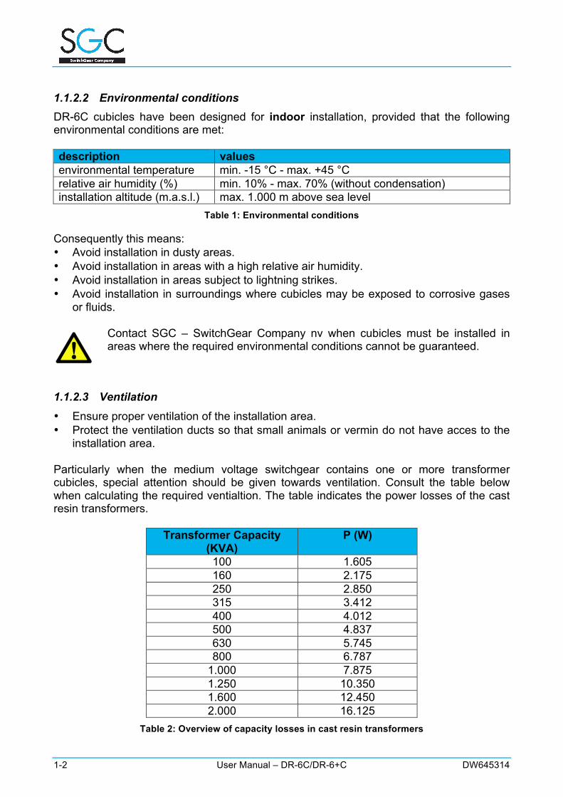
Particularly when the medium voltage switchgear contains one or more transformer cubicles, special attention should be given towards ventilation. Consult the table below when calculating the required ventialtion. The table indicates the power losses of the cast resin transformers.
Transformer Capacity
(KVA) P (W)
100 1.605 160 2.175 250 2.850 315 3.412 400 4.012 500 4.837 630 5.745 800 6.787
1.000 7.875 1.250 10.350 1.600 12.450 2.000 16.125
Table 2: Overview of capacity losses in cast resin transformers

DW645314 User Manual – DR-6C/DR-6+C 1-3
1.1.2.4 Free height of the installation area The free height of the installation room has to be at least 2.000 mm. Local power supply companies may however, require a larger minimum free height. An ideal, and generally accepted, value is 2500 mm.
Dry transformers with a capacity of ≥ 1250 KVA require a minimal height of at least 2.500 mm.
1.1.2.5 Sizes of the entrance doors to the installation area The provided dimensions apply to all doors that offer access to the installation room. These minimum requirements also apply if the installation room is not directly accessible from the outside.
description value Height of the access door min. 2.200 mm Width of the access door min. 100 mm + width of the widest cubicle
Table 3: Dimensions of the access doors
If the medium voltage switchgear does not contain any transformer cubicle(s), a minimal door height of 2.000 mm will be sufficient. If a transformer cubicle is included, the dimensions of the transformer always need to be taken into account. For the correct dimensions of the different cubicles, please see: “Dimensions & Weights”. If the medium voltage switchgear is to be installed in basements, an entrance hatch is required, whose length as well as width is at least 400 mm larger than the dimensions of the largest cubicle or transformer.
1.1.2.6 Free passage in front of the cubicles The free passage in front of the cubicles depends on the assembly of the medium voltage switchgear.
If the medium voltage switchgear does not contain any transformer cubicle(s), the minimum free passage is 800 mm. Medium voltage switchgear with a transformer cubicle having a capacity of ≥ 1.000 KVA requires a free passage of at least 2.000 mm.
1-4 User Manual – DR-6C/DR-6+C DW645314
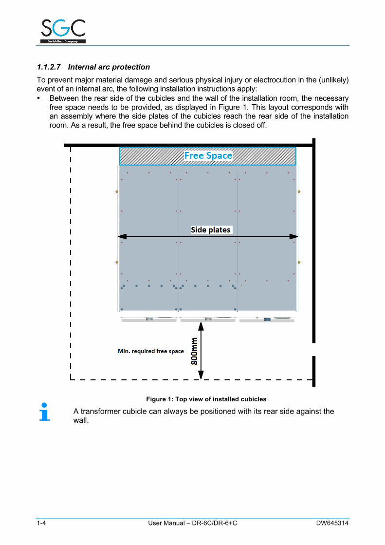
1.1.2.7 Internal arc protection To prevent major material damage and serious physical injury or electrocution in the (unlikely) event of an internal arc, the following installation instructions apply: • Between the rear side of the cubicles and the wall of the installation room, the necessary
free space needs to be provided, as displayed in Figure 1. This layout corresponds with an assembly where the side plates of the cubicles reach the rear side of the installation room. As a result, the free space behind the cubicles is closed off.
Figure 1: Top view of installed cubicles
A transformer cubicle can always be positioned with its rear side against the wall.
DW645314 User Manual – DR-6C/DR-6+C 1-5
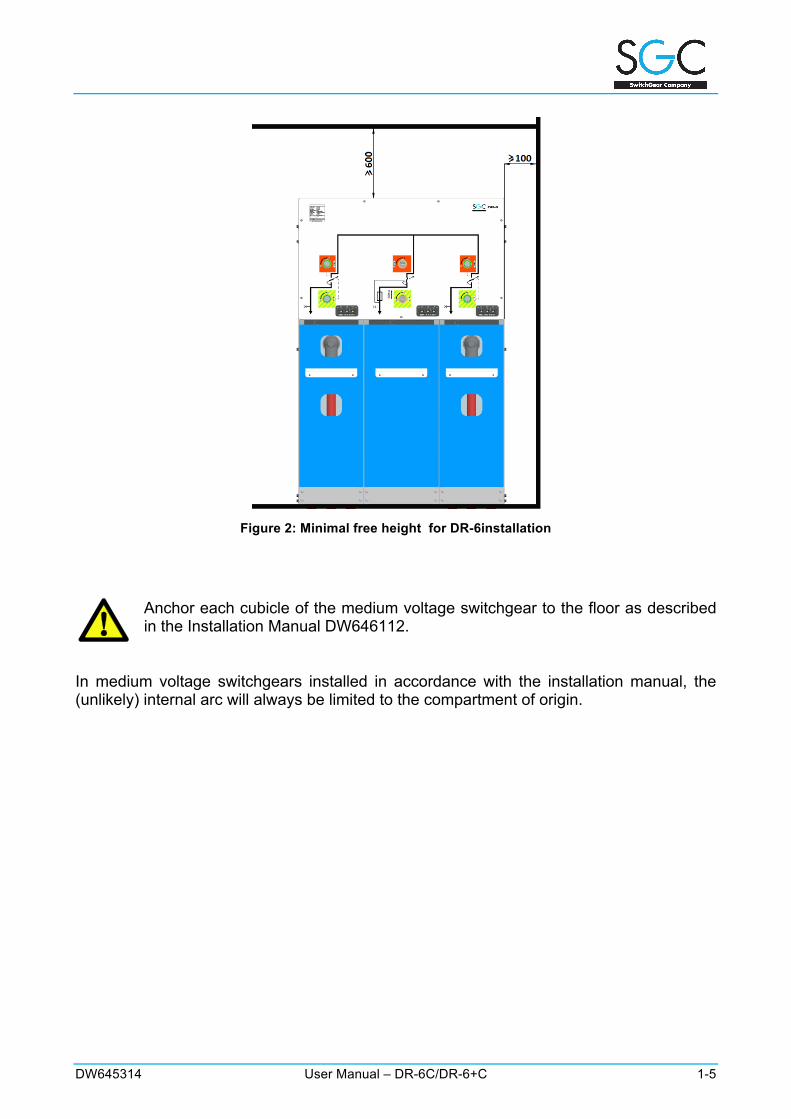
Figure 2: Minimal free height for DR-6installation
Anchor each cubicle of the medium voltage switchgear to the floor as described in the Installation Manual DW646112.
In medium voltage switchgears installed in accordance with the installation manual, the (unlikely) internal arc will always be limited to the compartment of origin.
1-6 User Manual – DR-6C/DR-6+C DW645314
Notes:
DW645314 User Manual – DR-6C/DR-6+C 2-1
2 USE
2.1 Safety instructions – use • See also "GENERAL INSTALLATION & SAFETY ".Use of the medium voltage
switchgear is restricted to qualified and trained operators, while observing the locally applicable safety instructions and guidelines.Ensure that when using the medium voltage switchgear the door is always properly closed and locked with a reliable padlock. When a door is open, switching is not possible.
2.2 Identification of the cubicles Every DR-6C medium-voltage cubicle is equipped with a identification plate and a stamped serial number.
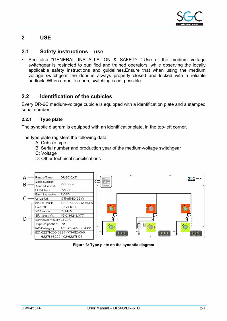
2.2.1 Type plate The synoptic diagram is equipped with an identificationplate, in the top-left corner. The type plate registers the following data:
A: Cubicle type B: Serial number and production year of the medium-voltage switchgear C: Voltage D: Other technical specifications
Figure 3: Type plate on the synoptic diagram
2-2 User Manual – DR-6C/DR-6+C DW645314
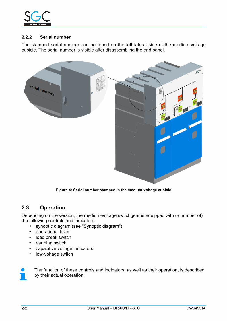
2.2.2 Serial number The stamped serial number can be found on the left lateral side of the medium-voltage cubicle. The serial number is visible after disassembling the end panel.
Figure 4: Serial number stamped in the medium-voltage cubicle
2.3 Operation Depending on the version, the medium-voltage switchgear is equipped with (a number of) the following controls and indicators:
• synoptic diagram (see "Synoptic diagram") • operational lever • load break switch • earthing switch • capacitive voltage indicators • low-voltage switch
The function of these controls and indicators, as well as their operation, is described by their actual operation.
DW645314 User Manual – DR-6C/DR-6+C 2-3
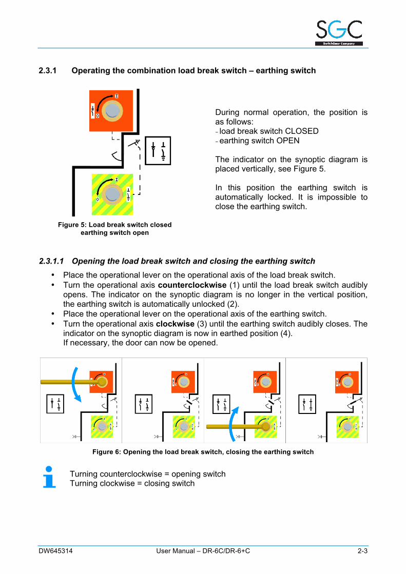
2.3.1 Operating the combination load break switch – earthing switch
Figure 5: Load break switch closed
earthing switch open
During normal operation, the position is as follows: − load break switch CLOSED − earthing switch OPEN The indicator on the synoptic diagram is placed vertically, see Figure 5. In this position the earthing switch is automatically locked. It is impossible to close the earthing switch.
2.3.1.1 Opening the load break switch and closing the earthing switch • Place the operational lever on the operational axis of the load break switch. • Turn the operational axis counterclockwise (1) until the load break switch audibly
opens. The indicator on the synoptic diagram is no longer in the vertical position, the earthing switch is automatically unlocked (2).
• Place the operational lever on the operational axis of the earthing switch. • Turn the operational axis clockwise (3) until the earthing switch audibly closes. The
indicator on the synoptic diagram is now in earthed position (4). If necessary, the door can now be opened.
Figure 6: Opening the load break switch, closing the earthing switch
Turning counterclockwise = opening switch Turning clockwise = closing switch
2-4 User Manual – DR-6C/DR-6+C DW645314
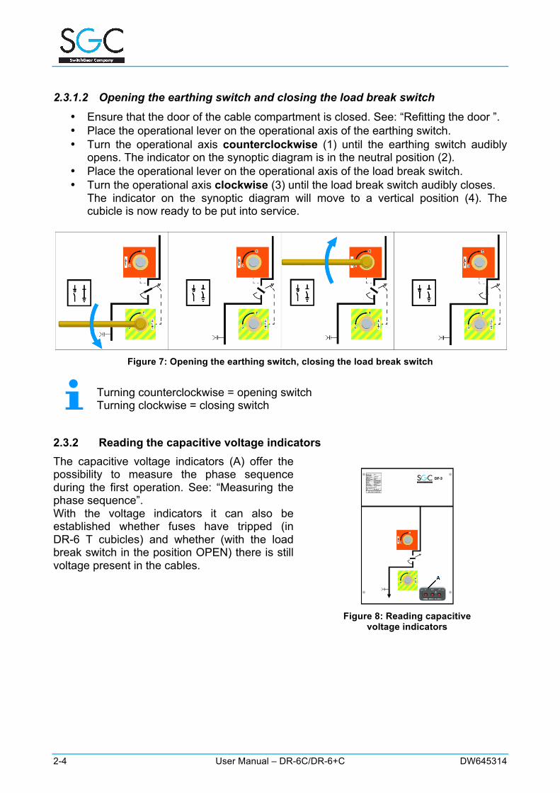
2.3.1.2 Opening the earthing switch and closing the load break switch • Ensure that the door of the cable compartment is closed. See: “Refitting the door ”. • Place the operational lever on the operational axis of the earthing switch. • Turn the operational axis counterclockwise (1) until the earthing switch audibly
opens. The indicator on the synoptic diagram is in the neutral position (2). • Place the operational lever on the operational axis of the load break switch. • Turn the operational axis clockwise (3) until the load break switch audibly closes.
The indicator on the synoptic diagram will move to a vertical position (4). The cubicle is now ready to be put into service.
Figure 7: Opening the earthing switch, closing the load break switch
Turning counterclockwise = opening switch Turning clockwise = closing switch
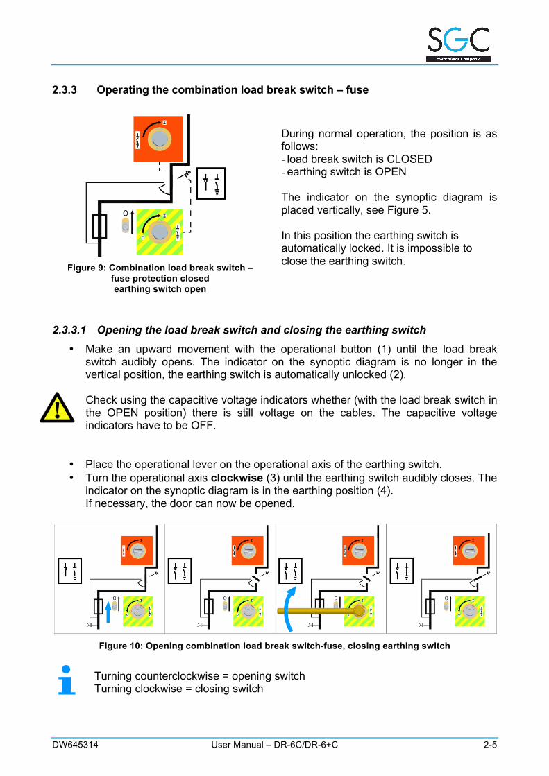
2.3.2 Reading the capacitive voltage indicators The capacitive voltage indicators (A) offer the possibility to measure the phase sequence during the first operation. See: “Measuring the phase sequence”. With the voltage indicators it can also be established whether fuses have tripped (in DR-6 T cubicles) and whether (with the load break switch in the position OPEN) there is still voltage present in the cables.
Figure 8: Reading capacitive
voltage indicators
DW645314 User Manual – DR-6C/DR-6+C 2-5
2.3.3 Operating the combination load break switch – fuse
Figure 9: Combination load break switch –
fuse protection closed earthing switch open
During normal operation, the position is as follows: − load break switch is CLOSED − earthing switch is OPEN The indicator on the synoptic diagram is placed vertically, see Figure 5. In this position the earthing switch is automatically locked. It is impossible to close the earthing switch.
2.3.3.1 Opening the load break switch and closing the earthing switch • Make an upward movement with the operational button (1) until the load break
switch audibly opens. The indicator on the synoptic diagram is no longer in the vertical position, the earthing switch is automatically unlocked (2). Check using the capacitive voltage indicators whether (with the load break switch in the OPEN position) there is still voltage on the cables. The capacitive voltage indicators have to be OFF.
• Place the operational lever on the operational axis of the earthing switch. • Turn the operational axis clockwise (3) until the earthing switch audibly closes. The
indicator on the synoptic diagram is in the earthing position (4). If necessary, the door can now be opened.
Figure 10: Opening combination load break switch-fuse, closing earthing switch
Turning counterclockwise = opening switch Turning clockwise = closing switch
2-6 User Manual – DR-6C/DR-6+C DW645314
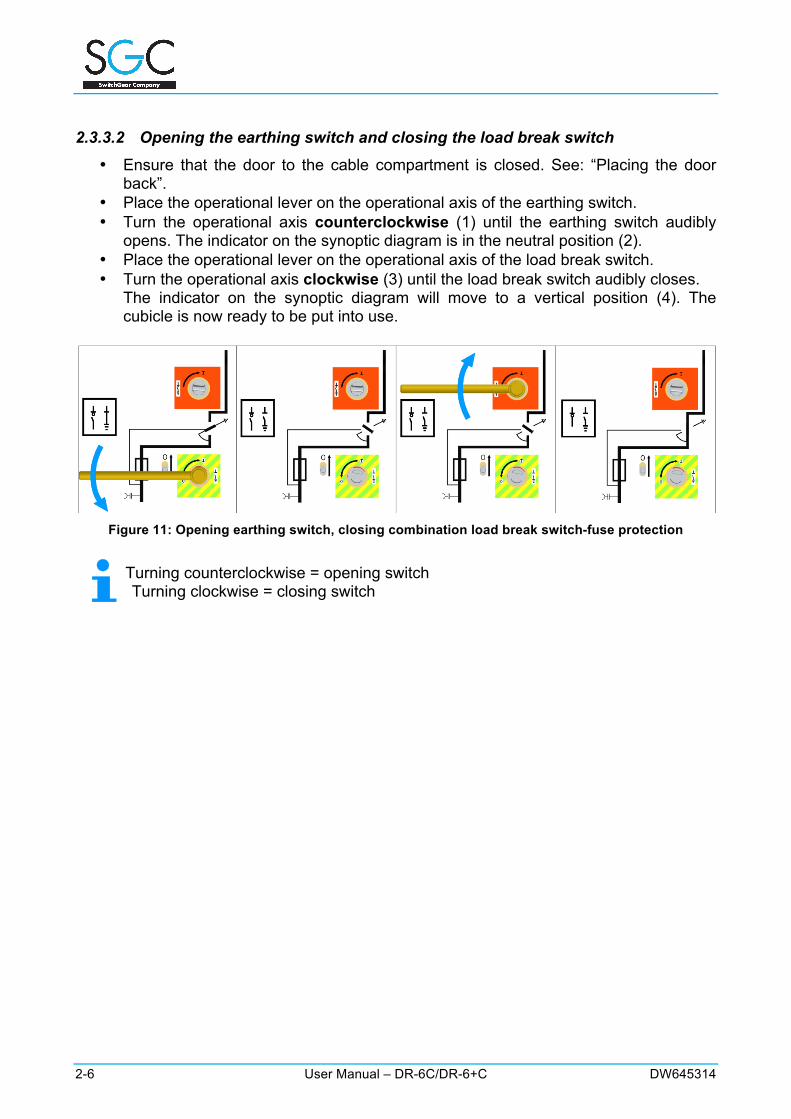
2.3.3.2 Opening the earthing switch and closing the load break switch • Ensure that the door to the cable compartment is closed. See: “Placing the door
back”. • Place the operational lever on the operational axis of the earthing switch. • Turn the operational axis counterclockwise (1) until the earthing switch audibly
opens. The indicator on the synoptic diagram is in the neutral position (2). • Place the operational lever on the operational axis of the load break switch. • Turn the operational axis clockwise (3) until the load break switch audibly closes.
The indicator on the synoptic diagram will move to a vertical position (4). The cubicle is now ready to be put into use.
Figure 11: Opening earthing switch, closing combination load break switch-fuse protection
Turning counterclockwise = opening switch Turning clockwise = closing switch
DW645314 User Manual – DR-6C/DR-6+C 2-7
2.4 Interlocks The interlocks below are provided by default on products in the DR-6 range. If other specifications are required, additional interlocks can be examined on simple request.
2.4.1 Interlocks between load break switch and earthing switch Load break switch in closed position The earthing switch is automatically locked in this position. It is impossible to close the earthing switch.
Load break switch open, earthing switch open In the neutral position, it is possible to switch either the earthing switch or the load break switch. Earthing switch in closed position The load break switch is automatically lockedin this position . It is not possible to close the load break switch.
2.4.2 Door interlock
2.4.2.1 Accessing the cable compartment Access towards the cable compartment is only possible if the load break switch is in the OPEN position and the earthing switch is in the CLOSED position.
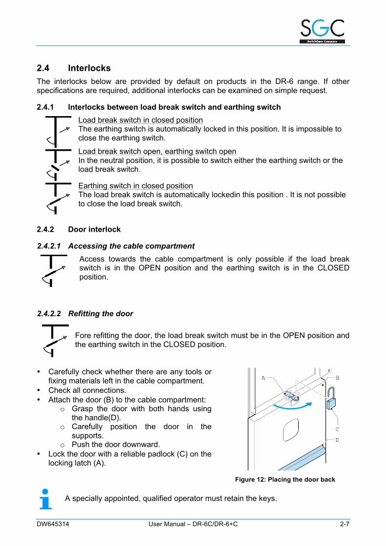
2.4.2.2 Refitting the door Fore refitting the door, the load break switch must be in the OPEN position and the earthing switch in the CLOSED position.
• Carefully check whether there are any tools or
fixing materials left in the cable compartment. • Check all connections. • Attach the door (B) to the cable compartment:
o Grasp the door with both hands using the handle(D).
o Carefully position the door in the supports.
o Push the door downward. • Lock the door with a reliable padlock (C) on the
locking latch (A).
Figure 12: Placing the door back A specially appointed, qualified operator must retain the keys.
2-8 User Manual – DR-6C/DR-6+C DW645314
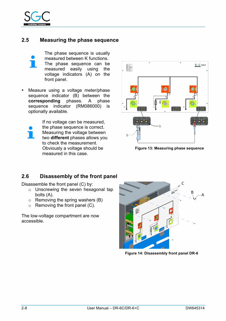
2.5 Measuring the phase sequence
The phase sequence is usually measured between K functions. The phase sequence can be measured easily using the voltage indicators (A) on the front panel.
• Measure using a voltage meter/phase sequence indicator (B) between the corresponding phases. A phase sequence indicator (RM086000) is optionally available.
If no voltage can be measured, the phase sequence is correct. Measuring the voltage between two different phases allows you to check the measurement. Obviously a voltage should be measured in this case.
Figure 13: Measuring phase sequence
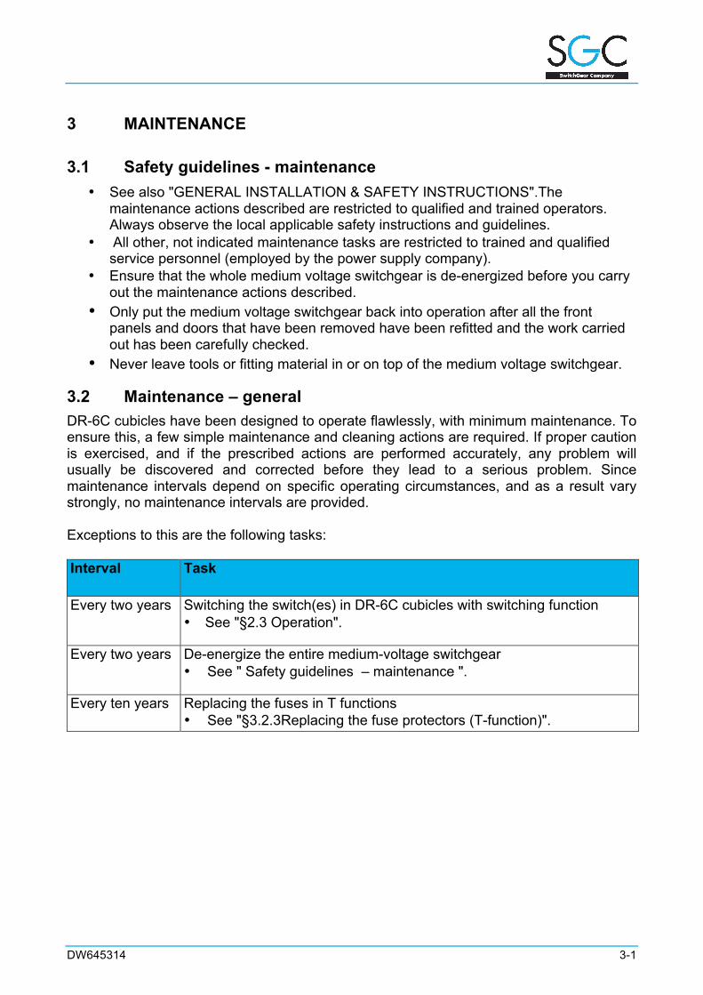
2.6 Disassembly of the front panel Disassemble the front panel (C) by:
o Unscrewing the seven hexagonal tap bolts (A).
o Removing the spring washers (B) o Removing the front panel (C).
The low-voltage compartment are now accessible.
Figure 14: Disassembly front panel DR-6

2-10 User Manual – DR-6C/DR-6+C DW645314
Notes:
DW645314 3-1
3 MAINTENANCE
3.1 Safety guidelines - maintenance • See also "GENERAL INSTALLATION & SAFETY INSTRUCTIONS".The
maintenance actions described are restricted to qualified and trained operators. Always observe the local applicable safety instructions and guidelines.
• All other, not indicated maintenance tasks are restricted to trained and qualified service personnel (employed by the power supply company).
• Ensure that the whole medium voltage switchgear is de-energized before you carry out the maintenance actions described.
• Only put the medium voltage switchgear back into operation after all the front panels and doors that have been removed have been refitted and the work carried out has been carefully checked.
• Never leave tools or fitting material in or on top of the medium voltage switchgear.
3.2 Maintenance – general DR-6C cubicles have been designed to operate flawlessly, with minimum maintenance. To ensure this, a few simple maintenance and cleaning actions are required. If proper caution is exercised, and if the prescribed actions are performed accurately, any problem will usually be discovered and corrected before they lead to a serious problem. Since maintenance intervals depend on specific operating circumstances, and as a result vary strongly, no maintenance intervals are provided. Exceptions to this are the following tasks: Interval Task
Every two years Switching the switch(es) in DR-6C cubicles with switching function • See "§2.3 Operation".
Every two years De-energize the entire medium-voltage switchgear • See " Safety guidelines – maintenance ".
Every ten years Replacing the fuses in T functions • See "§3.2.3Replacing the fuse protectors (T-function)".
3-2 DW645314
Important notice concerning DR-6C medium-voltage switchgear.
DR-6C medium-voltage switchgear requires minimum maintenance. It is of the “sealed for life type” and does not require an intervention when it comes to sealing, during the entire life cycle of the switchgear. The integrated RV-50 load break switches are developed according to IEC 62271-102 standards and have a mechanical life cycle of 1000 operations. The maintenance intervals can vary depending on the use of the load break switch. Nevertheless, a number of scheduled maintenance tasks are still required, as described in the previous table.
3.2.1 General control operations • Regularly perform a thorough, general visual inspection. • Check whether the cables are still connected properly.
3.2.1.1 Cleaning DR-6C cubicles Contamination of the DR-6C cubicles can initially be limited by respecting the recommendations regarding the installation area. See: “Recommendations – installation area”.
3.2.1.2 Cleaning the exterior • First read the safety guidelines. See: “Safety guidelines – maintenance”. • Clean the exterior with non-fluffy cloth and a non-corrosive cleaning agent. • Rub the cleaned surfaces thoroughly dry.
3.2.1.3 Condensation SGC - SwitchGear Company nv’s equipment is tested according to IEC 60932, procedure A, level 2. These tests serve to verify the proper functioning of the equipment in the presence of condensation. To avoid condensation, it is recommended to:
• Properly ventilate the room • Properly heat the room • Ensure a proper degree of humidity
If despite these measures, condensation does still appear, SGC - SwitchGear Company nv can optionally install heating resistors (30 W) in each cubicle.
DW645314 3-3
3.2.1.4 Cleaning the interior The entire interior of the DR-6C cubicles needs to be kept free from dust, moisture, and other contaminations. This applies in particular to the cable compartment.
A clean and dust-free interior facilitates dielectric characteristics and limits the leakage current to a minimum.
• De-enerzige the entire medium-voltage switchgear. See "Safety guidelines –
maintenance” • Disassemble the front panel. See "Disassembly of the front panel” • Remove the door. See "Accessing the cable compartment". • Clean the interior (including the cables) with a non-fluffy cloth and a non-corrosive
cleaning agent. • Rub the cleaned surfaces thoroughly dry to prevent surface oxidation, copper oxidation
and corrosion of the fitting materials. • Check all bolt-nut connections. • Fit the front panel. • Refit the door.
3.2.2 Switching the switches Switches that are used rarely or never, need to be switched at least every two years to check the functioning of the mechanical components. See "Operation".
3-4 DW645314
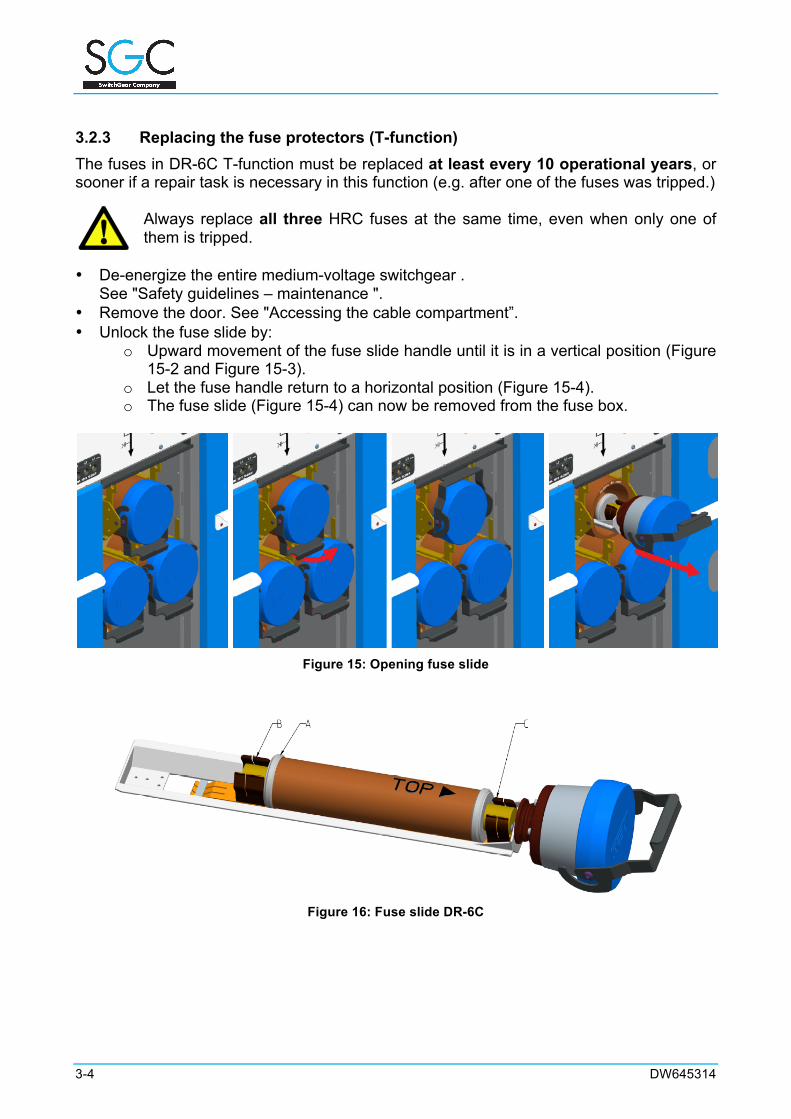
3.2.3 Replacing the fuse protectors (T-function) The fuses in DR-6C T-function must be replaced at least every 10 operational years, or sooner if a repair task is necessary in this function (e.g. after one of the fuses was tripped.)
Always replace all three HRC fuses at the same time, even when only one of them is tripped.
• De-energize the entire medium-voltage switchgear . See "Safety guidelines – maintenance ".
• Remove the door. See "Accessing the cable compartment”. • Unlock the fuse slide by:
o Upward movement of the fuse slide handle until it is in a vertical position (Figure 15-2 and Figure 15-3).
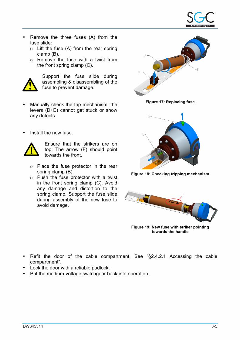
o Let the fuse handle return to a horizontal position (Figure 15-4). o The fuse slide (Figure 15-4) can now be removed from the fuse box.
Figure 15: Opening fuse slide
Figure 16: Fuse slide DR-6C
DW645314 3-5
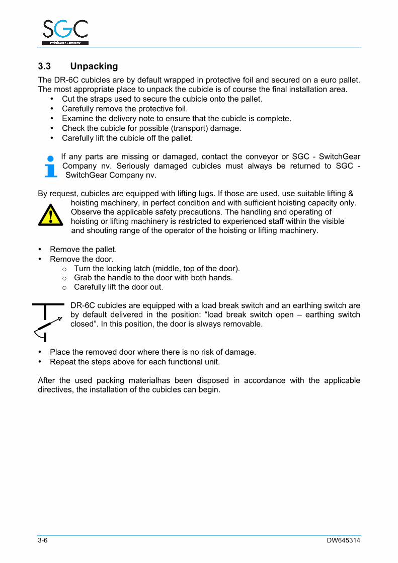
• Remove the three fuses (A) from the fuse slide: o Lift the fuse (A) from the rear spring
clamp (B). o Remove the fuse with a twist from
the front spring clamp (C).
Support the fuse slide during assembling & disassembling of the fuse to prevent damage.
• Manually check the trip mechanism: the
levers (D+E) cannot get stuck or show any defects.
• Install the new fuse.
Ensure that the strikers are on top. The arrow (F) should point towards the front.
o Place the fuse protector in the rear spring clamp (B).
o Push the fuse protector with a twist in the front spring clamp (C). Avoid any damage and distortion to the spring clamp. Support the fuse slide during assembly of the new fuse to avoid damage.
Figure 17: Replacing fuse
Figure 18: Checking tripping mechanism
Figure 19: New fuse with striker pointing
towards the handle
• Refit the door of the cable compartment. See "§2.4.2.1 Accessing the cable
compartment". • Lock the door with a reliable padlock. • Put the medium-voltage switchgear back into operation.
3-6 DW645314
3.3 Unpacking The DR-6C cubicles are by default wrapped in protective foil and secured on a euro pallet. The most appropriate place to unpack the cubicle is of course the final installation area.
• Cut the straps used to secure the cubicle onto the pallet. • Carefully remove the protective foil. • Examine the delivery note to ensure that the cubicle is complete. • Check the cubicle for possible (transport) damage. • Carefully lift the cubicle off the pallet.
If any parts are missing or damaged, contact the conveyor or SGC - SwitchGear Company nv. Seriously damaged cubicles must always be returned to SGC - SwitchGear Company nv.
By request, cubicles are equipped with lifting lugs. If those are used, use suitable lifting &
hoisting machinery, in perfect condition and with sufficient hoisting capacity only. Observe the applicable safety precautions. The handling and operating of hoisting or lifting machinery is restricted to experienced staff within the visible and shouting range of the operator of the hoisting or lifting machinery.
• Remove the pallet. • Remove the door.
o Turn the locking latch (middle, top of the door). o Grab the handle to the door with both hands. o Carefully lift the door out.
DR-6C cubicles are equipped with a load break switch and an earthing switch are by default delivered in the position: “load break switch open – earthing switch closed”. In this position, the door is always removable.
• Place the removed door where there is no risk of damage. • Repeat the steps above for each functional unit. After the used packing materialhas been disposed in accordance with the applicable directives, the installation of the cubicles can begin.
DW645314 4-1
4 DR-6C CUBICLES AND THE ENVIRONMENT
4.1 Packing materials Packing materials consist mainly of:
• (Untreated) wood • Plastic strips • Plastic film
Contact the local public cleaning department for the details of recycling or an environmentally friendly way of processing the packing materials Tender the packing material as instructed (separated).. In Belgium, Euro-pallets need to be returned to SGC - SwitchGear Company nv
after the installation of the cubicles.
4.2 Disposal of the cubicles With regards to reusing electrical components, SF6-gas (sulphur hexafluoride) filled switchgear material can be returned to SGC - SwitchGear Company nv at the end of its life span or when damaged. On consultation, complete DR-6cubiclescan also be returned. If this is not possible, the cubicles must be processed in an environmentally friendly way. Contact the local sanitation services for possible recycling and tender the material in the prescribed manner (separated).
4.3 Recuperation of SF6 gas The recuperation of SF6-gas in medium-voltage cubicles of the DR-6C type, concerns the gas-filled compartment with integrated load break switche RV-50. The stainless steel tank contains a gaseous volume of 0,342m³ with a pressure of 1.5 bar absolute at 20°C. Taking into account the dimensions and the volume of the gas, users are advised to have the recycling of gas-filled components done, at the end of the life-cycle, by a specialized company. In this case, the user will take into account the local regulations with regards to transport. Insofar as possible, the user will denote the predictable state of decomposition of the gas, in order to be able to provide adequate treatment. At end of the lifespan (usually 30 years), the decomposition degree of the gas will be considered as minor (see Table 1 – section 6 IEC 61634). The customer can also consult SGC - SwitchGear Company nv in order to recycle or recuperate the SF6 gas.

DW645314
THE SPECIALIST IN MEDIUM VOLTAGE SWITCHGEAR
DW6455314 ©2013 SGC - SwitchGear Company nv.