medium-voltage switching devices vacuum circuit-breaker
TRANSCRIPT
Medium-voltageswitching devices
Vacuum circuit-breakerSelection list
T&DMedium Voltage Switchgear

Terms of DeliveryThe General Terms of Delivery, as amended, shall apply.
IllustrationsThe illustrations are not binding.
3
Introduction
General description 4
Use, construction, method of operation 5
The basic technical-physical principlesfor switching in vacuum 8
Switching capacity 9
Vacuum circuit-breakers with fast auto-reclosure 12
Accessories 13
Specifications and tests 14
Mechanical reliability andadmissible switching cycles 15
Selection tables 12 kV17.5 kV24 kV 18
Circuit diagrams 28
Vacuum tester 34
Dimensions and weights 36
4
General description
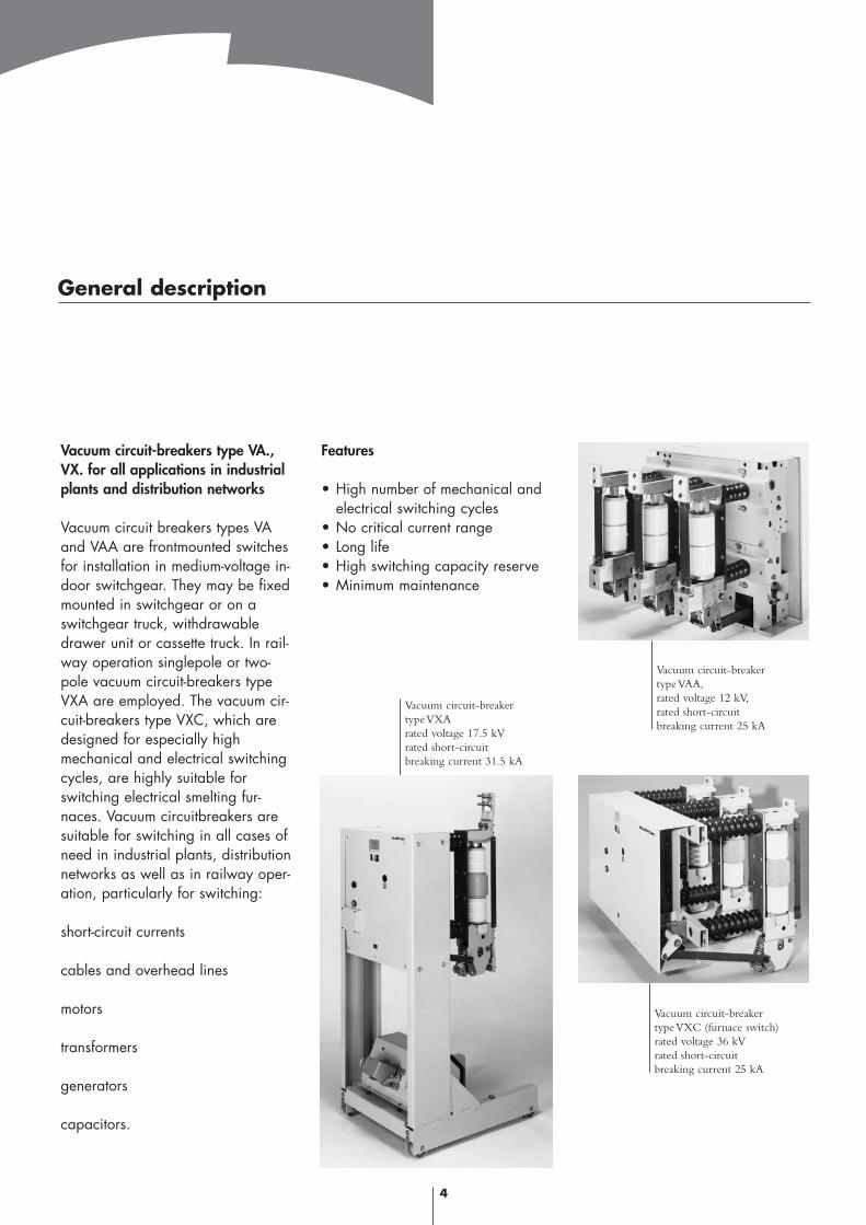
Vacuum circuit-breakers type VA.,VX. for all applications in industrialplants and distribution networks
Vacuum circuit breakers types VAand VAA are frontmounted switchesfor installation in medium-voltage in-door switchgear. They may be fixedmounted in switchgear or on aswitchgear truck, withdrawabledrawer unit or cassette truck. In rail-way operation singlepole or two-pole vacuum circuit-breakers typeVXA are employed. The vacuum cir-cuit-breakers type VXC, which aredesigned for especially highmechanical and electrical switchingcycles, are highly suitable forswitching electrical smelting fur-naces. Vacuum circuitbreakers aresuitable for switching in all cases ofneed in industrial plants, distributionnetworks as well as in railway oper-ation, particularly for switching:
short-circuit currents
cables and overhead lines
motors
transformers
generators
capacitors.
Features
• High number of mechanical and electrical switching cycles
• No critical current range• Long life• High switching capacity reserve• Minimum maintenance
Vacuum circuit-breakertype VXArated voltage 17.5 kVrated short-circuitbreaking current 31.5 kA
Vacuum circuit-breakertype VAA,rated voltage 12 kV,rated short-circuitbreaking current 25 kA
Vacuum circuit-breakertype VXC (furnace switch)rated voltage 36 kVrated short-circuitbreaking current 25 kA
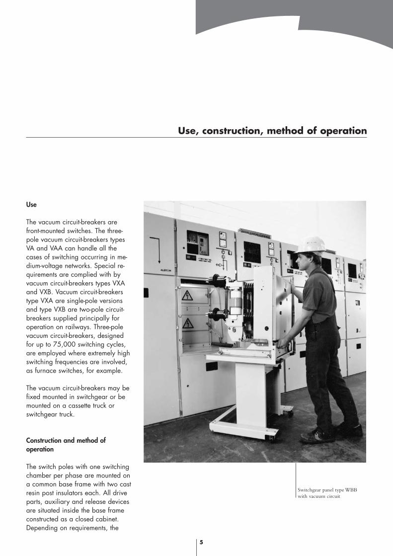
Use
The vacuum circuit-breakers arefront-mounted switches. The three-pole vacuum circuit-breakers typesVA and VAA can handle all thecases of switching occurring in me-dium-voltage networks. Special re-quirements are complied with byvacuum circuit-breakers types VXAand VXB. Vacuum circuit-breakerstype VXA are single-pole versionsand type VXB are two-pole circuit-breakers supplied principally foroperation on railways. Three-polevacuum circuit-breakers, designedfor up to 75,000 switching cycles,are employed where extremely highswitching frequencies are involved,as furnace switches, for example.
The vacuum circuit-breakers may befixed mounted in switchgear or bemounted on a cassette truck orswitchgear truck.
Construction and method of operation
The switch poles with one switchingchamber per phase are mounted ona common base frame with two castresin post insulators each. All driveparts, auxiliary and release devicesare situated inside the base frameconstructed as a closed cabinet. Depending on requirements, the
5
Use, construction, method of operation
Switchgear panel type WBBwith vacuum circuit
vacuum circuit-breakers may be pro-vided with auxiliary switches, auxil-iary current releases, indirect over-current releases and under-voltagereleases.
The vacuum circuit-breakers are fit-ted with an energy-storing drive formanual or electrical tensioning andoptionally for fast auto-reclosure.
The force required for making andbreaking is transmitted betweenenergy storing device and switchpoles by means of a hook stickmade from high-quality glass-fibrereinforced insulating material,which is substantially unloadedwhen the vacuum circuit-breaker ismade.
6
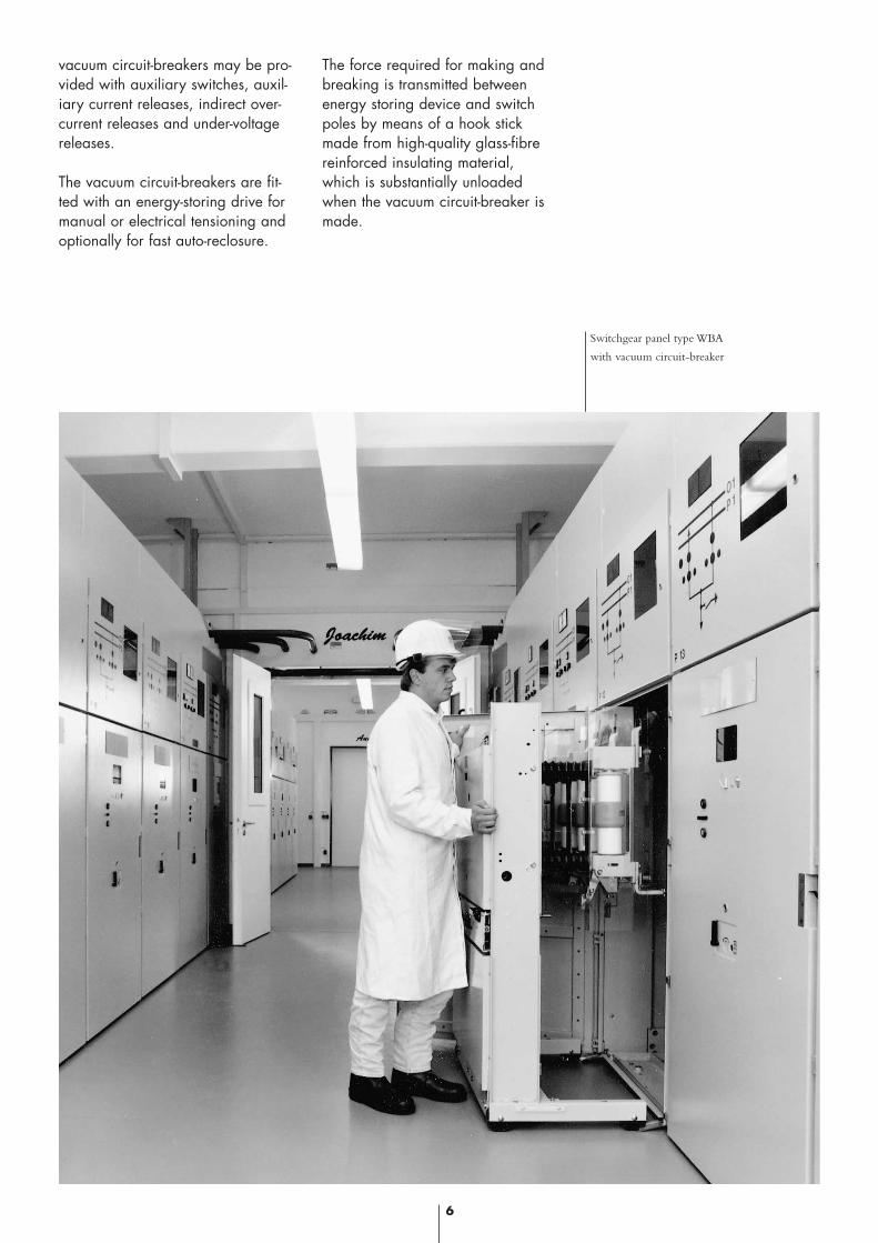
Switchgear panel type WBA
with vacuum circuit-breaker
Pole selection
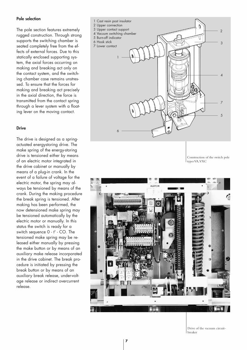
The pole section features extremelyrugged construction. Through strongsupports the switching chamber isseated completely free from the ef-fects of external forces. Due to thisstatically enclosed supporting sys-tem, the axial forces occurring onmaking and breaking act only onthe contact system, and the switch-ing chamber case remains unstres-sed. To ensure that the forces formaking and breaking act preciselyin the axial direction, the force istransmitted from the contact springthrough a lever system with a float-ing lever on the moving contact.
Drive
The drive is designed as a spring-actuated energystoring drive. Themake spring of the energy-storingdrive is tensioned either by meansof an electric motor integrated inthe drive cabinet or manually bymeans of a plug-in crank. In theevent of a failure of voltage for theelectric motor, the spring may al-ways be tensioned by means of thecrank. During the making procedurethe break spring is tensioned. Aftermaking has been performed, thenow detensioned make spring maybe tensioned automatically by theelectric motor or manually. In thisstatus the switch is ready for aswitch sequence 0 - t' - CO. Thetensioned make spring may be re-leased either manually by pressingthe make button or by means of anauxiliary make release incorporatedin the drive cabinet. The break pro-cedure is initiated by pressing thebreak button or by means of anauxiliary break release, under-volt-age release or indirect overcurrentrelease.
7
Construction of the switch poletypes VA,VXC
Drive of the vacuum circuit-breaker
1
6
2
3
4
7
5
1 Cast resin post insulator2 Upper connection3 Upper contact support4 Vacuum switching chamber5 Burn-off indicator6 Hook stick7 Lower contact
Breaking an AC current in a vacuumswitching chamber
Breaking a current in an installationfor the distribution of electricalpower is always performed by sep-arating two contact pieces of thecircuit-breaker contact. An extremelyhigh current density arises in thelast contact bridge before final me-chanical and thus galvanic separa-tion of the contact pieces. Duringthis event evaporation and ionisati-on take place of material, which ori-ginates from the electrode surfaceof the contact pieces. Thus, chargecarriers are available between theelectrodes. On breaking a short-cir-cuit current such a high number ofthem are present that the short-cir-cuit current continues to flow in un-changed magnitude at first. Thisphenomenon is called vacuum metalvapour arc.
The tendency of this vacuum metalvapour arc to resolve the initial con-centration originating from the lastcontact bridge into a large numberof partial arcs, is decisive for itssuitability as a switching element.These partial arcs need only a rela-tively low driving voltage, which re-sults in a reduced energy applica-tion.
The partial arcs move across theentire contact surface available,which remains relatively cold.When viewed optically the vacuumvapour arc in this state has a "dif-fuse" appearance and is thereforealso called a "diffuse vacuum va-pour arc". The partial arcs are ex-
tinguished one after the other accor-ding to their component of the cur-rent when the current drops, i.e. atthe moment the sinusoidal alternat-ing current approaches zero. Thegeneration of charge carriers is pro-portional to the momentary currentmagnitude. When the last partialarc is extinguished, the electricalconductivity of the breaker gap isreduced at a velocity which cor-responds to the diffusion velocity ofthe charge carriers in the electricalfield between the breaker contacts.
Without exploiting further physicaleffects the diffuse arc mode de-scribed above is restricted to mo-mentary current ratings of 10 kAapproximately. At higher currents amore concentrated type of dischar-ge of the metal vapour arc occurs.Peak events take place between thecharge carriers, which considerablyincrease the energy conversion ofthe discharge. A the same timelarge areas of the breaker contactsurface evaporate and metal vapourenters the space between the brea-ker contacts. This event still takesplace during the natural zero alsodue to the thermal delay, and brea-king would no longer be possibleunder the effect of recovery voltagein this situation because the chargecarrier concentration in the breakergap is still too high.
Therefore, the breaker contacts areso structured that the arc is so guid-ed that a magnetic field is produc-ed, which causes the arc to rotate.On decreasing arc current, just be-fore the natural current zero transit,
the contracted arc assumes a diffusedischarge mode once more.
At even higher break currents a fur-ther contact principle has proved itsvalue, the AMF (axial magneticfield) contact.
Vacuum switching contact with axialmagnetic field
lt is a physical phenomenon that thediffuse mode of a vacuum vapourarc is stabilised by a magneticfield, whose magnetic field orienta-tion corresponds to the dischargeorientation of the vacuum vapourarc. This axial magnetic field produ-ces a so-called cyclotron effect. Thecharged particles are driven intospiral paths of narrow diameter sothat filiform discharges are causedbetween the contact pieces. The dis-charge of the metal vapour arctherefore takes place exclusively inthe cylindrical space which is limit-ed by the two switching contact sur-faces.
Under exploitation of the effect ofan axial magnetic field the vacuumvapour arc could be developed toan almost "ideal" switching deviceeven for higher current ratings.
8
The physical-technical principles for switching in vacuum
The axial magnetic field of the vacu-um switching chamber
The physical phenomenon describ-ed above of the positive influencingof the arc by an axial magneticfield was explolted in two ways onthe development of the ALSTOMvacuum switching chambers.
By exploiting this effect the contactdimensions could be clearly re-duced but maintaining the perform-ance data. This allowed the imple-mentation of especially compactchamber design and the materiai-isation of a general-purpose vac-uum switching chamber for distribu-tion networks.
By means of the axial field contactsystem the physical limits of thetransversal magnetic field contactscould be clearly undercut. Thisagain led to the materialisation ofvacuum switching chambers for themost stringent performance require-ments.
Rated short-circuit breaking currentand partial load currents
In high-duty test shops in Germanyand abroad numerous series of testswitchings were performed to deter-mine the switching capacity of thedifferent circuit-breaker types. Apartfrom registering the breaking cur-rent and recovery voltage by oscil-loscope, special value was attachedto recording further important physi-cal data such as arc power, arc vol-tage and time-path processes. By re-ference to tbese data far-reachingknowledge is available in respect ofoptimum dimensioning and for pro-gressive technical im-provements.
Unbalanced breaking currents
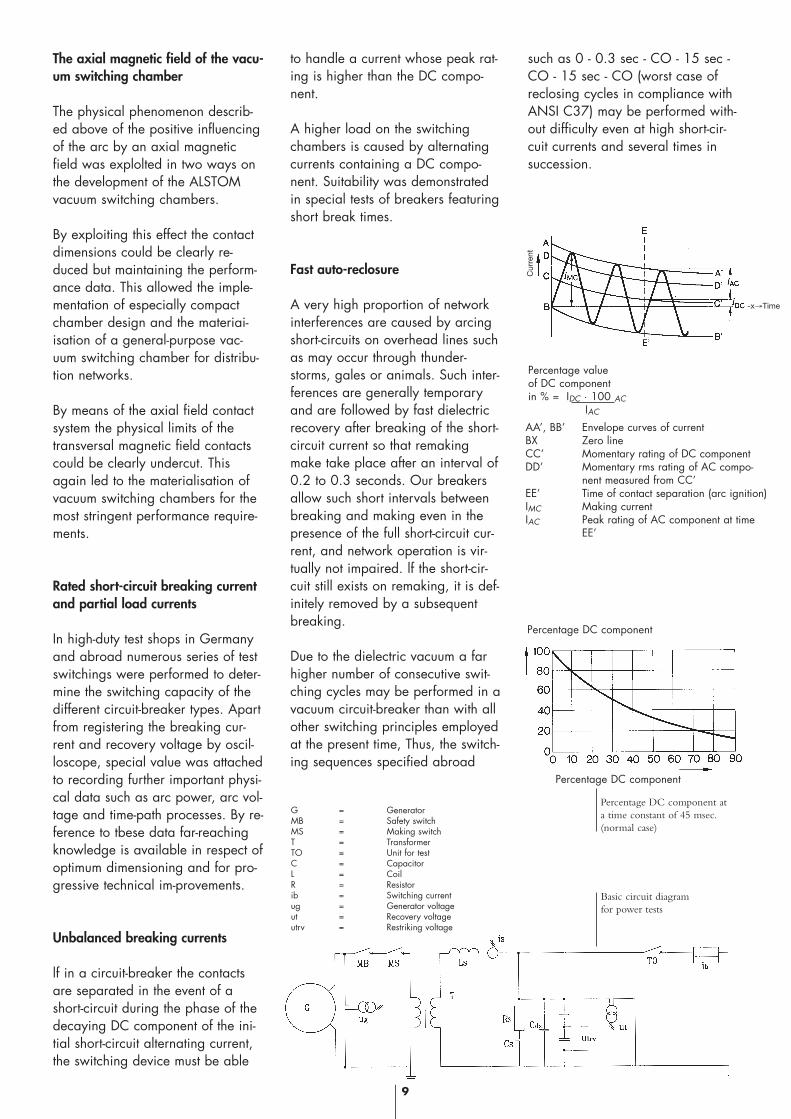
lf in a circuit-breaker the contactsare separated in the event of ashort-circuit during the phase of thedecaying DC component of the ini-tial short-circuit alternating current,the switching device must be able
to handle a current whose peak rat-ing is higher than the DC compo-nent.
A higher load on the switchingchambers is caused by alternatingcurrents containing a DC compo-nent. Suitability was demonstratedin special tests of breakers featuringshort break times.
Fast auto-reclosure
A very high proportion of networkinterferences are caused by arcingshort-circuits on overhead lines suchas may occur through thunder-storms, gales or animals. Such inter-ferences are generally temporaryand are followed by fast dielectricrecovery after breaking of the short-circuit current so that remakingmake take place after an interval of0.2 to 0.3 seconds. Our breakersallow such short intervals betweenbreaking and making even in thepresence of the full short-circuit cur-rent, and network operation is vir-tually not impaired. lf the short-cir-cuit still exists on remaking, it is def-initely removed by a subsequentbreaking.
Due to the dielectric vacuum a farhigher number of consecutive swit-ching cycles may be performed in avacuum circuit-breaker than with allother switching principles employedat the present time, Thus, the switch-ing sequences specified abroad
such as 0 - 0.3 sec - CO - 15 sec -CO - 15 sec - CO (worst case ofreclosing cycles in compliance withANSI C37) may be performed with-out difficulty even at high short-cir-cuit currents and several times insuccession.
9
Percentage valueof DC componentin % = IDC · 100 AC
IAC
AA’, BB’ Envelope curves of currentBX Zero lineCC’ Momentary rating of DC componentDD’ Momentary rms rating of AC compo-
nent measured from CC’EE’ Time of contact separation (arc ignition)IMC Making currentIAC Peak rating of AC component at time
EE’
-x→Time
Cur
rent
Basic circuit diagram for power tests
Percentage DC component at a time constant of 45 msec.(normal case)
G = GeneratorMB = Safety switchMS = Making switchT = TransformerTO = Unit for testC = Capacitor L = CoilR = Resistorib = Switching currentug = Generator voltageut = Recovery voltageutrv = Restriking voltage
Percentage DC component
Percentage DC component
10
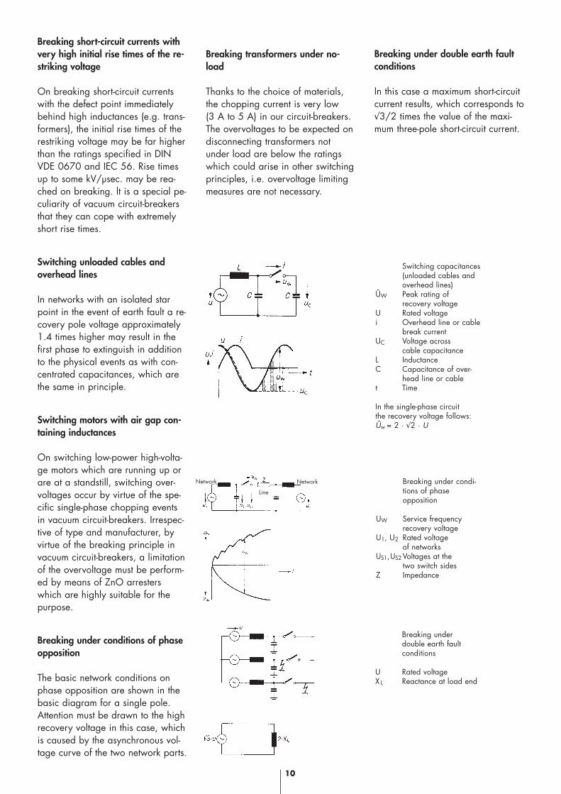
Breaking short-circuit currents withvery high initial rise times of the re-striking voltage
On breaking short-circuit currentswith the defect point immediatelybehind high inductances (e.g. trans-formers), the initial rise times of therestriking voltage may be far higherthan the ratings specified in DINVDE 0670 and IEC 56. Rise timesup to some kV/µsec. may be rea-ched on breaking. lt is a special pe-culiarity of vacuum circuit-breakersthat they can cope with extremelyshort rise times.
Switching unloaded cables andoverhead lines
In networks with an isolated starpoint in the event of earth fault a re-covery pole voltage approximately1.4 times higher may result in thefirst phase to extinguish in additionto the physical events as with con-centrated capacitances, which arethe same in principle.
Switching motors with air gap con-taining inductances
On switching low-power high-volta-ge motors which are running up orare at a standstill, switching over-voltages occur by virtue of the spe-cific single-phase chopping eventsin vacuum circuit-breakers. Irrespec-tive of type and manufacturer, byvirtue of the breaking principle invacuum circuit-breakers, a limitationof the overvoltage must be perform-ed by means of ZnO arresterswhich are highly suitable for thepurpose.
Breaking under conditions of phaseopposition
The basic network conditions onphase opposition are shown in thebasic diagram for a single pole. Attention must be drawn to the highrecovery voltage in this case, whichis caused by the asynchronous vol-tage curve of the two network parts.
Breaking transformers under no-load
Thanks to the choice of materials,the chopping current is very low (3 A to 5 A) in our circuit-breakers.The overvoltages to be expected ondisconnecting transformers notunder load are below the ratingswhich could arise in other switchingprinciples, i.e. overvoltage limitingmeasures are not necessary.
Breaking under double earth faultconditions
In this case a maximum short-circuitcurrent results, which corresponds to√3/2 times the value of the maxi-mum three-pole short-circuit current.
Breaking under double earth fault conditions
U Rated voltageX L Reactance at load end
Breaking under condi- tions of phaseopposition
UW Service frequencyrecovery voltage
U1, U2 Rated voltageof networks
US1,US2 Voltages at thetwo switch sides
Z Impedance
Switching capacitances(unloaded cables andoverhead lines)
ÛW Peak rating ofrecovery voltage
U Rated voltagei Overhead line or cable
break currentUC Voltage across
cable capacitanceL InductanceC Capacitance of over-
head line or cablet Time
In the single-phase circuitthe recovery voltage follows:Ûw = 2 · √2 · U
Line
NetworkNetwork
11
Switching of capacitor banks
Vacuum circuit-breakers are de-signed especially for switching inthe capacitive current circuit. Theycan disconnect capacitors up to thehighest battery power without restri-king and thus without overvoltages.
The problem of switching capacitiveloads consists of handling relativelyhigh restriking voltage ratings. Thedielectric strength of the extinguis-hing gap must be reestablished im-mediately after extinguishing the ca-pacitive current so quickly that therestriking voltage resulting from thesum of remaining DC voltage at net-work frequency and at the dis-connected capacitance does notcause break down of the quenchinggap or cause the occurrence of in-admissible overoltages in the loads.
In the case that one or several ca-pacitors shall be connected parallelto a capacitor bank already con-nected to voltage, high-frequencyadaptation events take place be-tween the battery systems with highpeak currents, which could consti-tute a higher load for the quenchingchambers than the current load onswitching short-circuits, a case ofswitching to which special attentionmust be paid on the design of theswitching chambers.
3
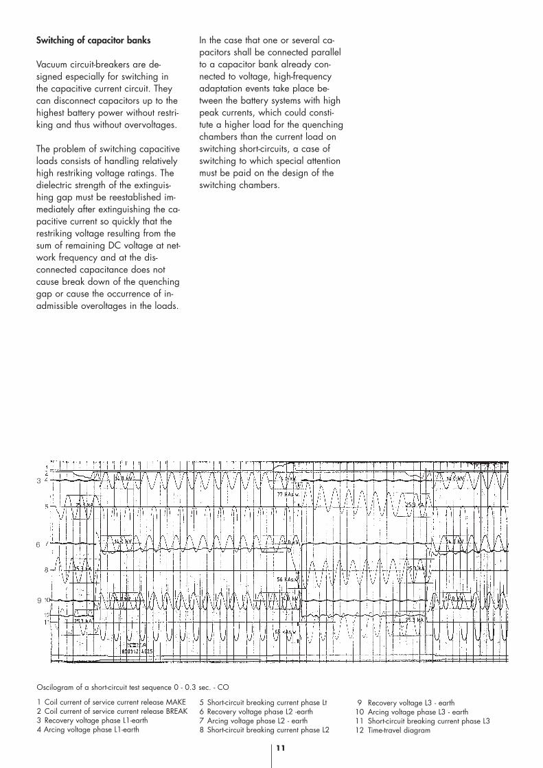
1 Coil current of service current release MAKE2 Coil current of service current release BREAK3 Recovery voltage phase L1-earth4 Arcing voltage phase L1-earth
5 Short-circuit breaking current phase Lt6 Recovery voltage phase L2 -earth7 Arcing voltage phase L2 - earth8 Short-circuit breaking current phase L2
9 Recovery voltage L3 - earth10 Arcing voltage phase L3 - earth11 Short-circuit breaking current phase L312 Time-travel diagram
6
9
Oscilogram of a short-circuit test sequence 0 - 0.3 sec. - CO
12
All vacuum circuit-breakers may befitted with fast auto-reclosure.
Method of operation When a short-circuit occurs an over-current relay applies a pulse to theauxiliary break release after thepreset short switching time and thebreaker is disconnected.
On expiry of the preset interval amake instruction is applied througha normally-open contact of the relayfor fast reclosure to the auxiliarymake release.
lf the short-circuit is still present afurther "Break" instruction is appliedby the overcurrent relay and thebreaker is finally disconnected. Afurther make instruction is not gener-ated by the relay for fast reclosure.
Vacuum circuit-breakers with fast auto-reclosure
Rated switching sequences
Rated switching sequences
0–3 min – CO – 3 min – CO
0–0.3s – CO – 3 min – CO
CO – 15s – CO
0-0.3s – CO – 15s - CO up to0-0.3s – CO – 15s - CO – 15s – CO – 15s – CO
0-15s –C’O – 15s – C’O - 15s – C’O – 15s – C’O
0-15s –C’O – 15s – C’O - 15s – C’O – 15s – C’O15s - C’O – 15s – C’O - 15s – C’O – 15s - C’O – 15 – C’OC Making with rated short-circuit making currentC’ Making with rated currentO Breaking with rated short-circuit breaking current
Designationwithout fastauto-reclosurewith fastauto-reclosure
reclosing cycles
Thunderstormcycle
Thunderstormcycle
Regulations
DIN VDE, IEC 56
DIN VDE, IEC 56
DIN VDE, IEC,ANSI-Standard C37
ANSI-Standard C37
Customerspecification
Customer specification
Remarks
Cf. selection tables
Cf. selection tables
Cf. selection tablescolumn “with fast auto-reclosure”
on enquiry
Cf. selection tables Tested by FGH
on enquiry Tested by FGH
13
Releases
Auxiliary releases(open-circuit indirect over-current re-leases) The excitation voltage is applied tothe coil of the auxiliary releasethrough a release contact of an au-xiliary current source. The applica-tion of the pulse may be initiatedmanually, by an auxiliary currentswitch, over-current release or un-dervoltage release. On connectionto AC voltage, the voltage is ap-plied to the coil through a rectifierincorporated in the breaker cabinet.Since the coil is designed for shortexcitation only, the exciter circuit iscontrolled by an auxiliary switchcontact driven by the breaker shaftthat interrupts the circuit after re-lease.
Secondary releases(transformer-operated releases) Secondary releases are used for theautomatic release of switching de-vices on the occurrence of short-cir-cuits and overcurrent. On responseof the protective system the releaseis excited by transformer currentand effects release of the switchingdevice in this way. These releasesare supplied for transformer second-ary currents of 0.5 A and 1 A.
Undervoltage releases Voltage is constantly applied to un-dervoltage releases by the auxiliary
current source. When the auxiliarycurrent circuit is interrupted or thevoltage drops greatly, the switchingdevice is released without anydelay. lf the undervoltage release issupplied by a voltage transformerdownstream from the breaker, aholding device may be fitted whichprevents release of the breaker notcompletely made.
Auxiliary current releases
Auxiliary switchesAuxiliary switches are always ac-tuated by the breaker shaft directthrough an intermediate linkage:their position always agrees withthe position of the main contacts. Ingeneral the circuit-breakers areequipped with a 12-element auxilia-ry switch: 8 switch elements are re-served for the circuit (cf. circuit dia-gram). For further circuits up to 8switch elements may be fitted addi-tionally. Moreover, the switching de-vice may be equipped with a me-chanically delayed switching ele-ment (single-pole wiper, T ≥ 50msec.).
Push switchesThe push switches are snap-actingswitches, which are attached to thedrive. In contrast to auxiliary swit-ches, snap-acting switches are notautomatically dependent on the po-
sition of the switching device butare actuated, for example, bymeans of cams or by elementsmounted on the breaker. The auxil-iary current switches are suppliedwired as far as the terminal strip (toorder with plug and plug lower sec-tion in compliance with DIN43460, draft Sept. 92).
Trucks
Trucks for circuit-breakers are madefrom bevelled metal sheets and sec-tional steel and are provided withcastors. Binding dimensional draw-ings are supplied on request.
Overvoltage arresters
Overvoltage arresters must be usedto protect the high-voltage motor cir-cuits against overvoltages. To deter-mine the type of arrester needed thefollowing data must be mentioned:rated motor voltage max. ambient temperaturetype of transformer star point earth-fault duration.
Accessories
14
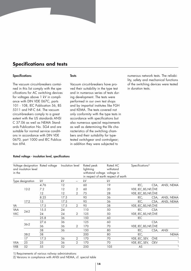
Specifications
The vacuum circuit-breakers contai-ned in this list comply with the spe-cifications for AC switching devicesfor voltages above 1 kV in compli-ance with DIN VDE 067C, parts101 - 108, IEC Publication 56, BS5311 and NF-C 64. The vacuumcircuit-breakers comply to a greatextent with the US standards ANSIC 37.06 as weil as NEMA Stand-ards Publication No. SG4 and aresuitable for normal service conditi-ons in accordance with DIN VDE0670, part 1000 and IEC Publica-tion 694.
Tests
Vacuum circuit-breakers have pro-ved their suitability in the type testand in numerous series of tests dur-ing development. The tests wereperformed in our own test shopsand by impartial institutes like FGHand KEMA. The tests covered notonly conformity with the type tests inaccordance with specifications butalso numerous special requirementsas well as determining the life cha-racteristics of the switching cham-bers and their suitability for type-tested switchgear and controlgear;in addition they were subjected to
numerous network tests. The reliabi-lity, safety and mechanical functionsof the switching devices were testedin duration tests.
Rated voltage - insulation level, specifications
Voltage designation Rated voltage Insulation level Rated peak Rated AC Specifications2)
and insulation level lightning withstandin the withstand voltage voltage in
in respect of earth respect of earthType designation kV kV – kV kV
4.76 12 60 19 IEC, CSA, ANSI, NEMA12-2 7.2 12 2 60 20 VDE, IEC,BS,NF,ÖVE
12 12 2 75 28 VDE, IEC,BS,NF,ÖVE8.25 17.5 95 36 IEC, CSA, ANSI, NEMA
17-2 15 17.5 95 36 IEC, CSA, ANSI, NEMAVA 17.5 17.5 2 95 38 VDE, IEC,BS,NF,ÖVEVAA 15.5 24 110 50 IEC CSAVXC
24-224 24 2 125 50 VDE, IEC,BS,NF,ÖVE25.8 36 150 60 IEC
36-227.6 36 125 60 CSA36 36 2 170 70 VDE, IEC,BS,NF,ÖVE38 36 150 80 IEC, CSA, ANSI
38-2 38 200 80 IEC, NEMA17 17.5 36 2 170 70 VDE, IEC,SEV, ÖVE 1)
VXA 25 25 36 2 170 70 VDE, IEC,SEV, ÖEV 1)
VXB 52 55 52 250 105 AS 1)
1) Requirements of various railway administrations2) Versions in compliance with ANSI and NEMA, cf. special table
Specifications and tests
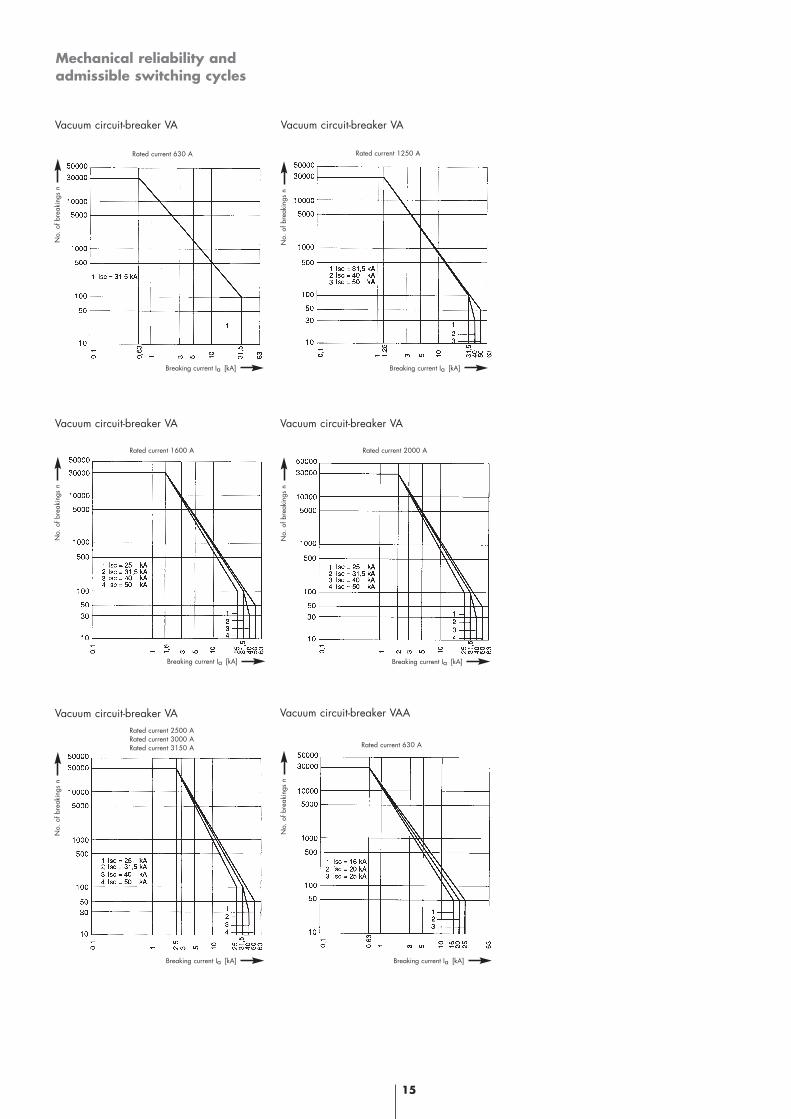
Mechanical reliability andadmissible switching cycles
15
Vacuum circuit-breaker VA Vacuum circuit-breaker VA
Vacuum circuit-breaker VA Vacuum circuit-breaker VA
Vacuum circuit-breaker VA Vacuum circuit-breaker VAA
Rated current 630 A Rated current 1250 A
Rated current 2000 ARated current 1600 A
Rated current 2500 ARated current 3000 ARated current 3150 A Rated current 630 A
No.
of b
reak
ings
n
No.
of b
reak
ings
n
No.
of b
reak
ings
n
No.
of b
reak
ings
n
No.
of b
reak
ings
n
No.
of b
reak
ings
n
Breaking current Ia [kA] Breaking current Ia [kA]
Breaking current Ia [kA]Breaking current Ia [kA]
Breaking current Ia [kA]Breaking current Ia [kA]
16
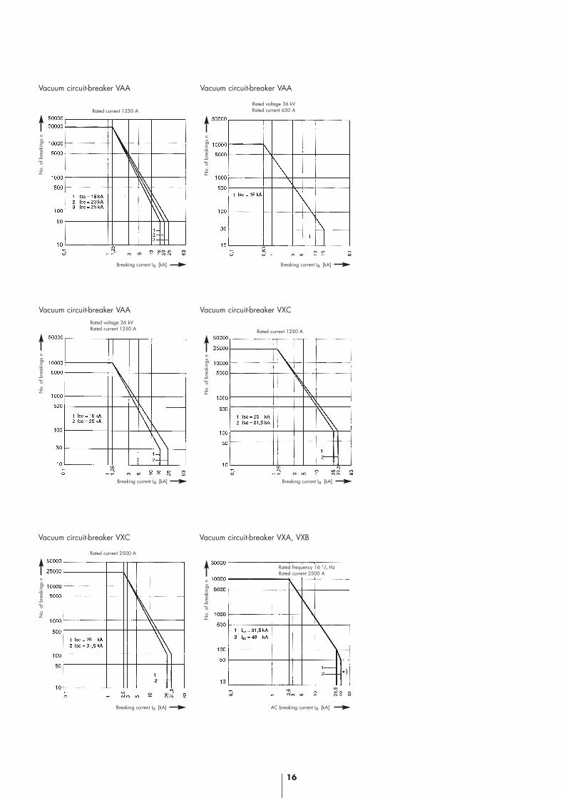
Vacuum circuit-breaker VAA Vacuum circuit-breaker VAA
Vacuum circuit-breaker VAA Vacuum circuit-breaker VXC
Vacuum circuit-breaker VXC Vacuum circuit-breaker VXA, VXB
Rated current 1250 A
Rated current 1250 A
Rated current 2500 A
Rated frequency 16 2/3 HzRated current 2500 A
Rated voltage 36 kVRated current 630 A
Rated voltage 36 kVRated current 1250 A
No.
of b
reak
ings
n
Breaking current Ia [kA]
No.
of b
reak
ings
n
Breaking current Ia [kA]
No.
of b
reak
ings
n
Breaking current Ia [kA]
No.
of b
reak
ings
n
Breaking current Ia [kA]
No.
of b
reak
ings
n
Breaking current Ia [kA]
No.
of b
reak
ings
n
AC breaking current Ia [kA]
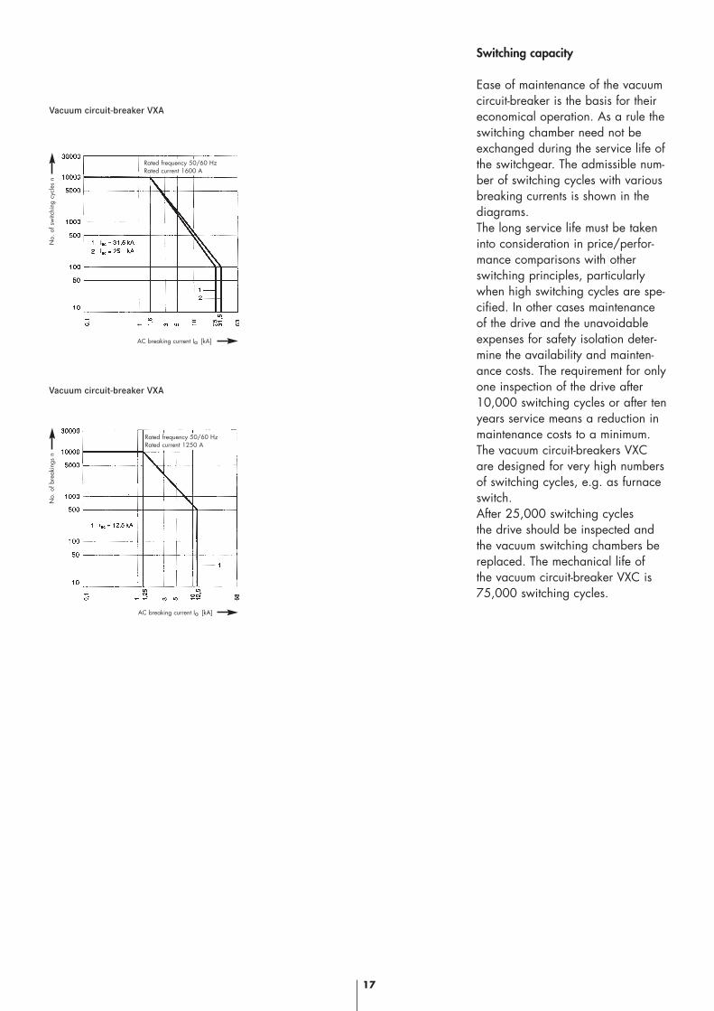
Switching capacity
Ease of maintenance of the vacuumcircuit-breaker is the basis for theireconomical operation. As a rule theswitching chamber need not beexchanged during the service life ofthe switchgear. The admissible num-ber of switching cycles with variousbreaking currents is shown in thediagrams.The long service life must be takeninto consideration in price/perfor-mance comparisons with otherswitching principles, particularlywhen high switching cycles are spe-cified. In other cases maintenanceof the drive and the unavoidableexpenses for safety isolation deter-mine the availability and mainten-ance costs. The requirement for onlyone inspection of the drive after10,000 switching cycles or after tenyears service means a reduction inmaintenance costs to a minimum.The vacuum circuit-breakers VXCare designed for very high numbersof switching cycles, e.g. as furnaceswitch.After 25,000 switching cyclesthe drive should be inspected andthe vacuum switching chambers bereplaced. The mechanical life of the vacuum circuit-breaker VXC is75,000 switching cycles.
17
Vacuum circuit-breaker VXA
Vacuum circuit-breaker VXA
Rated frequency 50/60 HzRated current 1600 A
Rated frequency 50/60 HzRated current 1250 A
No.
of s
witc
hing
cyc
les
n
AC breaking current Ia [kA]
No.
of b
reak
ings
n
AC breaking current Ia [kA]
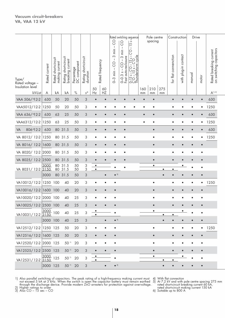
Vacuum circuit-breakersVA, VAA 12 kV
18
VAA 506/ 12-2 630 50 20 50 3 • • • • • • • • • • • 630
VAA5012/12-2 1250 50 20 50 3 • • • • • • • • • • • 1250
VAA 636/ 12-2 630 63 25 50 3 • • • • • • • • • • 630
VAA6312/12-2 1250 63 25 50 3 • • • • • • • • • • 1250
VA 806 12-2 630 80 31.5 50 3 • • • • • • • • • 630
VA 8012/ 12-2 1250 80 31.5 50 3 • • • • • • • • • 1250
VA 8016/ 12-2 1600 80 31.5 50 3 • • • • • • • • •
VA 8020/ 12-2 2000 80 31.5 50 3 • • • • • • • • •
VA 8025/ 12-2 2500 80 31.5 50 3 • • • • • • • • •
3000 80 31.5 50 3 • • •VA 8031/ 12-2 3150 80 31.5 50 3 • • • • • • •
3000 80 31.5 50 3 • • • • • • •
VA10012/ 12-2 1250 100 40 20 3 • • • • • • • • 1250
VA10016/ 12-2 1600 100 40 20 3 • • • • • • • •
VA10020/ 12-2 2000 100 40 25 3 • • • • • • • •
VA10025/ 12-2 2500 100 40 25 3 • • • • • • • •
3000 100 40 25 3 • • • • • •VA10031/ 12-2 3150 • • •
3000 100 40 25 3 • • • • • • •
VA12512/ 12-2 1250 125 50 20 3 • • • • • • • • 1250
VA12516/ 12-2 1600 125 50 20 3 • • • • • • • •
VA12520/ 12-2 2000 125 50 20 3 • • • • • • • •
VA12525/ 12-2 2500 125 50 20 3 • • • • • • • •
3000 125 50 20 3 • • • • • •VA12531/ 12-2 3150 • • •
3000 125 50 20 3 • • • • • • •
Rated switching sequence Pole centre Construction Drivespacing
Type/Rated voltage –Insulation level 50 60 160 210 275
kV-List A kA kA % s4) Hz HZ mm mm mm A1) 2)
Rate
d cu
rren
t
Rate
d sh
ort-c
ircui
tm
akin
g cu
rren
t
Ratin
g sh
ort-c
ircui
tbr
eaki
ng c
urre
nt
Perc
enta
ge
D
C c
ompo
nent
Ratin
g sh
ort-c
ircui
t du
ratio
n
Rate
d fre
quen
cy
0–3
min
– C
O –
3 m
in –
CO
0–0.
3 s
– C
O –
3 m
in –
CO
Fast
auto
-recl
osur
e0–
15 s
– C’
O –
15
s – C
’O –
15
s–C’
O –
15
s –
C’O
Thun
ders
torm
cyc
le
for
flat c
onne
nctio
n
with
plu
g-in
con
tact
man
ual
mot
or
Rate
d br
eaki
ng c
urre
nton
sw
itchi
ng c
apac
itors
6)
6)
6)
5)
5)
5)
5)
3)
3)
3)
1) Also parallel switching of capacitors. The peak rating of a high-frequency making current mustnot exceed 5 kA at 3 kHz. When the switch is open the capacitor battery must remain earthed through the discharge device. Provide modern ZnO arresters for protection against overvoltage.
2) Higher ratings to order3) Also CO – 15 sec – CO
4) With flat connection5) At 7.2 kV and with pole centre spacing 275 mm
rated short-circuit breaking current 60 kA,rated short-circuit making current 150 kA
6) Suitable up to 800 A
with
rat
ed c
urre
nt
with
rat
ed s
hort-
circ
uit
brea
king
cur
rent
Clo
sing
tim
e1)
Arc
ing
time
Aux
iliar
y m
ake
rele
ase
19
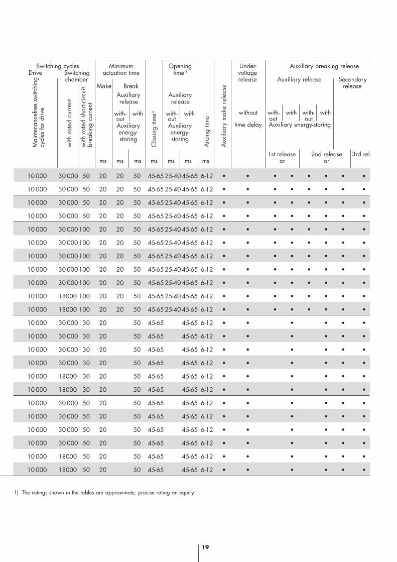
10 000 30 000 50 20 20 50 45-65 25-40 45-65 6-12 • • • • • • • •
10 000 30 000 50 20 20 50 45-65 25-40 45-65 6-12 • • • • • • • •
10 000 30 000 50 20 20 50 45-65 25-40 45-65 6-12 • • • • • • • •
10 000 30 000 50 20 20 50 45-65 25-40 45-65 6-12 • • • • • • • •
10 000 30 000100 20 20 50 45-65 25-40 45-65 6-12 • • • • • • • •
10 000 30 000100 20 20 50 45-65 25-40 45-65 6-12 • • • • • • • •
10 000 30 000100 20 20 50 45-65 25-40 45-65 6-12 • • • • • • • •
10 000 30 000100 20 20 50 45-65 25-40 45-65 6-12 • • • • • • • •
10 000 30 000100 20 20 50 45-65 25-40 45-65 6-12 • • • • • • • •
10 000 18000 100 20 20 50 45-65 25-40 45-65 6-12 • • • • • • • •
10 000 18000 100 20 20 50 45-65 25-40 45-65 6-12 • • • • • • • •
10 000 30 000 30 20 50 45-65 45-65 6-12 • • • • • •
10 000 30 000 30 20 50 45-65 45-65 6-12 • • • • • •
10 000 30 000 30 20 50 45-65 45-65 6-12 • • • • • •
10 000 30 000 30 20 50 45-65 45-65 6-12 • • • • • •
10 000 18000 30 20 50 45-65 45-65 6-12 • • • • • •
10 000 18000 30 20 50 45-65 45-65 6-12 • • • • • •
10 000 30 000 50 20 50 45-65 45-65 6-12 • • • • • •
10 000 30 000 50 20 50 45-65 45-65 6-12 • • • • • •
10 000 30 000 50 20 50 45-65 45-65 6-12 • • • • • •
10 000 30 000 50 20 50 45-65 45-65 6-12 • • • • • •
10 000 18000 50 20 50 45-65 45-65 6-12 • • • • • •
10 000 18000 50 20 50 45-65 45-65 6-12 • • • • • •
Switching cycles Minimum Opening Under- Auxiliary breaking releaseDrive Switching actuation time time1) voltage
chamberMake Break
release Auxiliary release Secondaryrelease
1st release 2nd release 3rd rel.ms ms ms ms ms ms ms or or
Auxiliaryrelease
with- withoutAuxiliaryenergy-storing
Auxiliaryrelease
with- withoutAuxiliaryenergy-storing
without
time delay
with- with with- without outAuxiliary energy-storing
Mai
nten
ance
free
switc
hing
cycl
es fo
r dr
ive
1) The ratings shown in the tables are approximate, precise rating on equiry
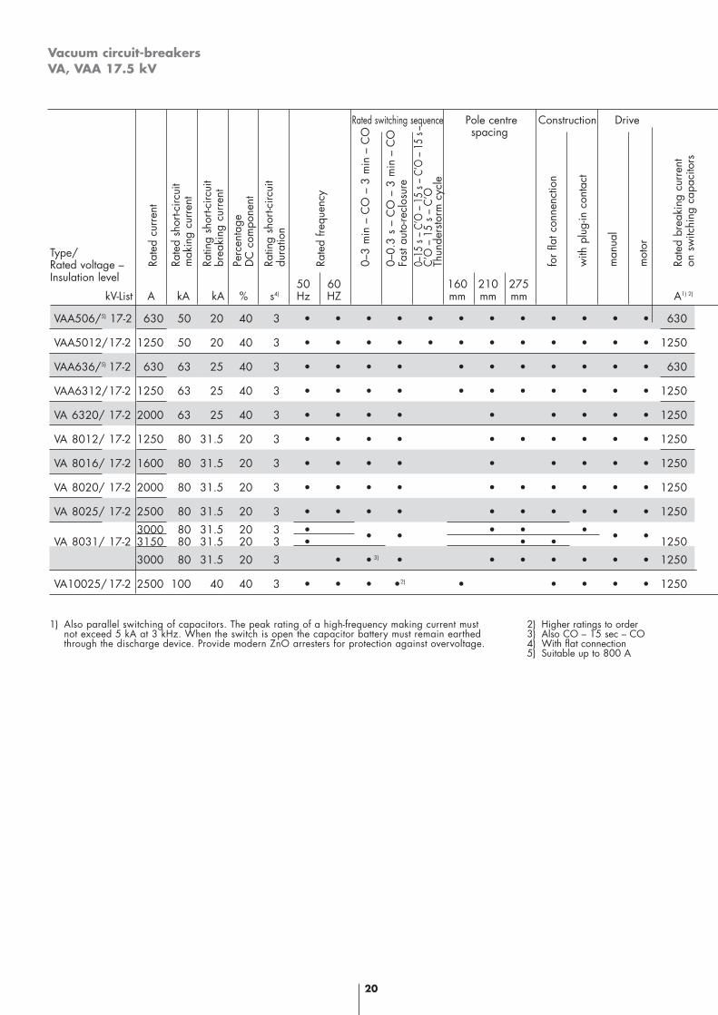
Vacuum circuit-breakersVA, VAA 17.5 kV
20
VAA506/5) 17-2 630 50 20 40 3 • • • • • • • • • • • • 630
VAA5012/17-2 1250 50 20 40 3 • • • • • • • • • • • • 1250
VAA636/5) 17-2 630 63 25 40 3 • • • • • • • • • • • 630
VAA6312/17-2 1250 63 25 40 3 • • • • • • • • • • • 1250
VA 6320/ 17-2 2000 63 25 40 3 • • • • • • • • • 1250
VA 8012/ 17-2 1250 80 31.5 20 3 • • • • • • • • • • 1250
VA 8016/ 17-2 1600 80 31.5 20 3 • • • • • • • • • 1250
VA 8020/ 17-2 2000 80 31.5 20 3 • • • • • • • • • • 1250
VA 8025/ 17-2 2500 80 31.5 20 3 • • • • • • • • • • 1250
3000 80 31.5 20 3 • • • •VA 8031/ 17-2 3150 80 31.5 20 3 • • • • • • • 1250
3000 80 31.5 20 3 • • • • • • • • • 1250
VA10025/ 17-2 2500 100 40 40 3 • • • •2) • • • • • 1250
Rated switching sequence Pole centre Construction Drivespacing
Type/Rated voltage –Insulation level 50 60 160 210 275
kV-List A kA kA % s4) Hz HZ mm mm mm A1) 2)
Rate
d cu
rren
t
Rate
d sh
ort-c
ircui
tm
akin
g cu
rren
t
Ratin
g sh
ort-c
ircui
tbr
eaki
ng c
urre
nt
Perc
enta
ge
D
C c
ompo
nent
Ratin
g sh
ort-c
ircui
t du
ratio
n
Rate
d fre
quen
cy
0–3
min
– C
O –
3 m
in –
CO
0–0.
3 s
– C
O –
3 m
in –
CO
Fast
auto
-recl
osur
e0–
15 s
– C’
O –
15
s – C
’O –
15
s–C’
O –
15
s –
C’O
Thun
ders
torm
cyc
le
for
flat c
onne
nctio
n
with
plu
g-in
con
tact
man
ual
mot
or
Rate
d br
eaki
ng c
urre
nton
sw
itchi
ng c
apac
itors
3)
1) Also parallel switching of capacitors. The peak rating of a high-frequency making current mustnot exceed 5 kA at 3 kHz. When the switch is open the capacitor battery must remain earthed through the discharge device. Provide modern ZnO arresters for protection against overvoltage.
2) Higher ratings to order3) Also CO – 15 sec – CO4) With flat connection5) Suitable up to 800 A
with
rat
ed c
urre
nt
with
rat
ed s
hort-
circ
uit
brea
king
cur
rent
Clo
sing
tim
e1)
Arc
ing
time
Aux
iliar
y m
ake
rele
ase
21
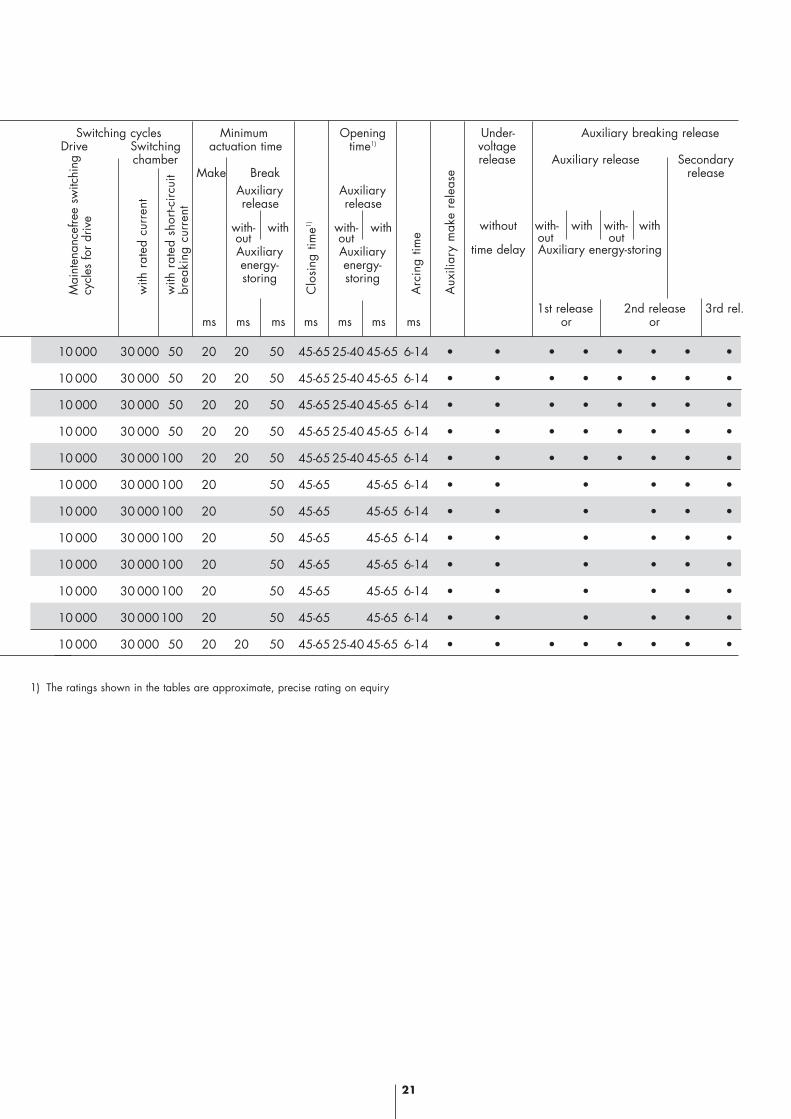
10 000 30 000 50 20 20 50 45-65 25-40 45-65 6-14 • • • • • • • •
10 000 30 000 50 20 20 50 45-65 25-40 45-65 6-14 • • • • • • • •
10 000 30 000 50 20 20 50 45-65 25-40 45-65 6-14 • • • • • • • •
10 000 30 000 50 20 20 50 45-65 25-40 45-65 6-14 • • • • • • • •
10 000 30 000100 20 20 50 45-65 25-40 45-65 6-14 • • • • • • • •
10 000 30 000100 20 50 45-65 45-65 6-14 • • • • • •
10 000 30 000100 20 50 45-65 45-65 6-14 • • • • • •
10 000 30 000100 20 50 45-65 45-65 6-14 • • • • • •
10 000 30 000100 20 50 45-65 45-65 6-14 • • • • • •
10 000 30 000100 20 50 45-65 45-65 6-14 • • • • • •
10 000 30 000100 20 50 45-65 45-65 6-14 • • • • • •
10 000 30 000 50 20 20 50 45-65 25-40 45-65 6-14 • • • • • • • •
Switching cycles Minimum Opening Under- Auxiliary breaking releaseDrive Switching actuation time time1) voltage
chamberMake Break
release Auxiliary release Secondaryrelease
1st release 2nd release 3rd rel.ms ms ms ms ms ms ms or or
Auxiliaryrelease
with- withoutAuxiliaryenergy-storing
Auxiliaryrelease
with- withoutAuxiliaryenergy-storing
without
time delay
with- with with- without outAuxiliary energy-storing
Mai
nten
ance
free
switc
hing
cycl
es fo
r dr
ive
1) The ratings shown in the tables are approximate, precise rating on equiry
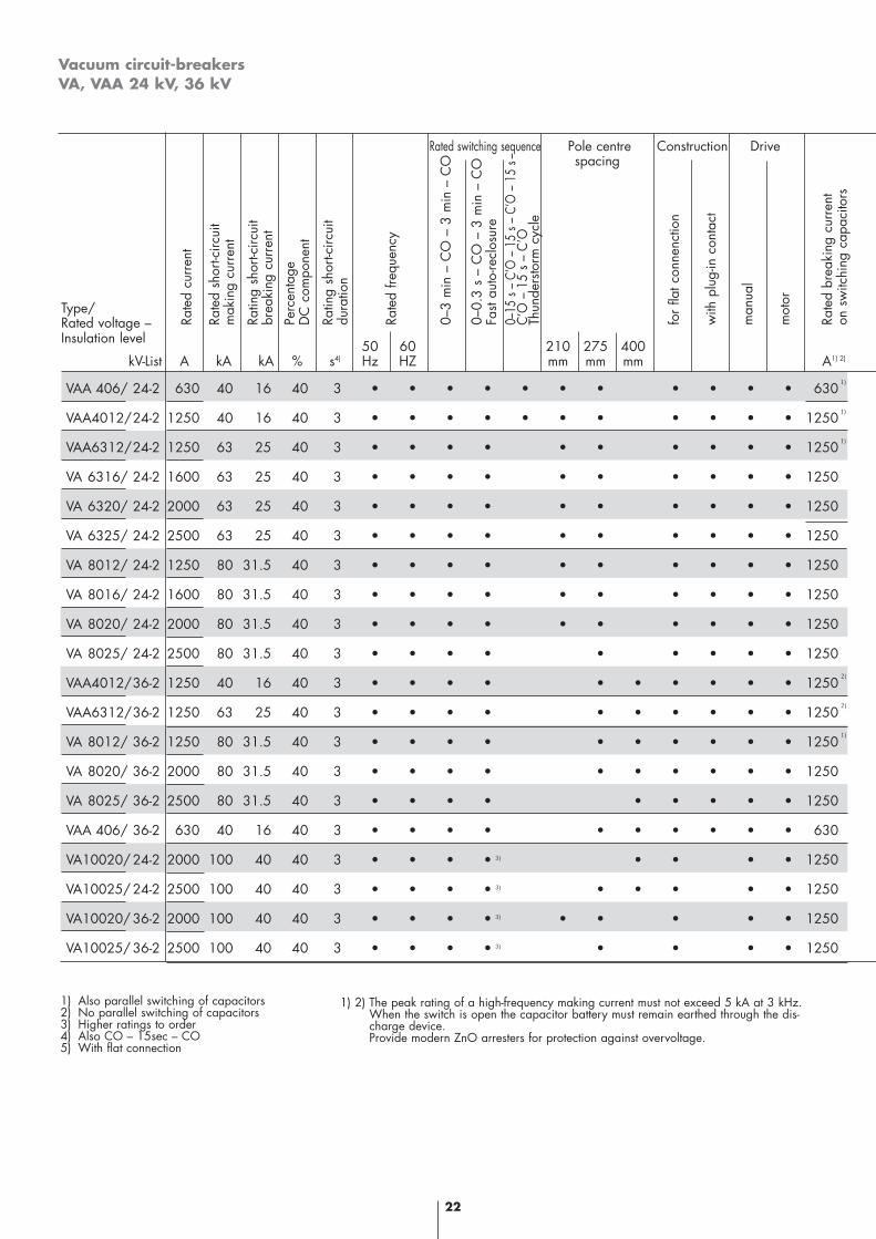
Vacuum circuit-breakersVA, VAA 24 kV, 36 kV
22
VAA 406/ 24-2 630 40 16 40 3 • • • • • • • • • • • 630
VAA4012/24-2 1250 40 16 40 3 • • • • • • • • • • • 1250
VAA6312/24-2 1250 63 25 40 3 • • • • • • • • • • 1250
VA 6316/ 24-2 1600 63 25 40 3 • • • • • • • • • • 1250
VA 6320/ 24-2 2000 63 25 40 3 • • • • • • • • • • 1250
VA 6325/ 24-2 2500 63 25 40 3 • • • • • • • • • • 1250
VA 8012/ 24-2 1250 80 31.5 40 3 • • • • • • • • • • 1250
VA 8016/ 24-2 1600 80 31.5 40 3 • • • • • • • • • • 1250
VA 8020/ 24-2 2000 80 31.5 40 3 • • • • • • • • • • 1250
VA 8025/ 24-2 2500 80 31.5 40 3 • • • • • • • • • 1250
VAA4012/36-2 1250 40 16 40 3 • • • • • • • • • • 1250
VAA6312/36-2 1250 63 25 40 3 • • • • • • • • • • 1250
VA 8012/ 36-2 1250 80 31.5 40 3 • • • • • • • • • • 1250
VA 8020/ 36-2 2000 80 31.5 40 3 • • • • • • • • • • 1250
VA 8025/ 36-2 2500 80 31.5 40 3 • • • • • • • • • 1250
VAA 406/ 36-2 630 40 16 40 3 • • • • • • • • • • 630
VA10020/ 24-2 2000 100 40 40 3 • • • • • • • • 1250
VA10025/ 24-2 2500 100 40 40 3 • • • • • • • • • 1250
VA10020/ 36-2 2000 100 40 40 3 • • • • • • • • • 1250
VA10025/ 36-2 2500 100 40 40 3 • • • • • • • • 1250
Rated switching sequence Pole centre Construction Drivespacing
Type/Rated voltage –Insulation level 50 60 210 275 400
kV-List A kA kA % s4) Hz HZ mm mm mm A1) 2)
Rate
d cu
rren
t
Rate
d sh
ort-c
ircui
tm
akin
g cu
rren
t
Ratin
g sh
ort-c
ircui
tbr
eaki
ng c
urre
nt
Perc
enta
ge
D
C c
ompo
nent
Ratin
g sh
ort-c
ircui
t du
ratio
n
Rate
d fre
quen
cy
0–3
min
– C
O –
3 m
in –
CO
0–0.
3 s
– C
O –
3 m
in –
CO
Fast
auto
-recl
osur
e0–
15 s
– C’
O –
15
s – C
’O –
15
s–C’
O –
15
s –
C’O
Thun
ders
torm
cyc
le
for
flat c
onne
nctio
n
with
plu
g-in
con
tact
man
ual
mot
or
Rate
d br
eaki
ng c
urre
nton
sw
itchi
ng c
apac
itors
3)
3)
3)
3)
1)
1)
1)
2)
2)
1)
1) Also parallel switching of capacitors2) No parallel switching of capacitors3) Higher ratings to order4) Also CO – 15sec – CO5) With flat connection
1) 2) The peak rating of a high-frequency making current must not exceed 5 kA at 3 kHz.When the switch is open the capacitor battery must remain earthed through the dis-charge device.Provide modern ZnO arresters for protection against overvoltage.
with
rat
ed c
urre
nt
with
rat
ed s
hort-
circ
uit
brea
king
cur
rent
Clo
sing
tim
e1)
Arc
ing
time
Aux
iliar
y m
ake
rele
ase
23
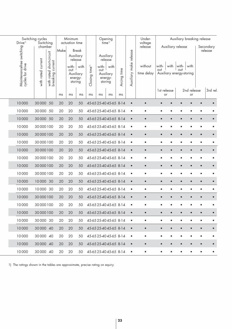
10 000 30 000 50 20 20 50 45-65 25-40 45-65 8-14 • • • • • • • •
10 000 30 000 50 20 20 50 45-65 25-40 45-65 8-14 • • • • • • • •
10 000 30 000 50 20 20 50 45-65 25-40 45-65 8-14 • • • • • • • •
10 000 30 000100 20 20 50 45-65 25-40 45-65 8-14 • • • • • • • •
10 000 30 000100 20 20 50 45-65 25-40 45-65 8-14 • • • • • • • •
10 000 30 000100 20 20 50 45-65 25-40 45-65 8-14 • • • • • • • •
10 000 30 000100 20 20 50 45-65 25-40 45-65 8-14 • • • • • • • •
10 000 30 000100 20 20 50 45-65 25-40 45-65 8-14 • • • • • • • •
10 000 30 000100 20 20 50 45-65 25-40 45-65 8-14 • • • • • • • •
10 000 30 000100 20 20 50 45-65 25-40 45-65 8-14 • • • • • • • •
10 000 10 000 30 20 20 50 45-65 25-40 45-65 8-14 • • • • • • • •
10 000 10 000 30 20 20 50 45-65 25-40 45-65 8-14 • • • • • • • •
10 000 30 000100 20 20 50 45-65 25-40 45-65 8-14 • • • • • • • •
10 000 30 000100 20 20 50 45-65 25-40 45-65 8-14 • • • • • • • •
10 000 30 000100 20 20 50 45-65 25-40 45-65 8-14 • • • • • • • •
10 000 30 000 30 20 20 50 45-65 25-40 45-65 8-14 • • • • • • • •
10 000 30 000 40 20 20 50 45-65 25-40 45-65 8-14 • • • • • • • •
10 000 30 000 40 20 20 50 45-65 25-40 45-65 8-14 • • • • • • • •
10 000 30 000 40 20 20 50 45-65 25-40 45-65 8-14 • • • • • • • •
10 000 30 000 40 20 20 50 45-65 25-40 45-65 8-14 • • • • • • • •
Switching cycles Minimum Opening Under- Auxiliary breaking releaseDrive1) Switching actuation time time1) voltage
chamberMake Break
release Auxiliary release Secondaryrelease
1st release 2nd release 3rd rel.ms ms ms ms ms ms ms or or
Auxiliaryrelease
with- withoutAuxiliaryenergy-storing
Auxiliaryrelease
with- withoutAuxiliaryenergy-storing
without
time delay
with- with with- without outAuxiliary energy-storing
Mai
nten
ance
free
switc
hing
cycl
es fo
r dr
ive
1) The ratings shown in the tables are approximate, precise rating on equiry.
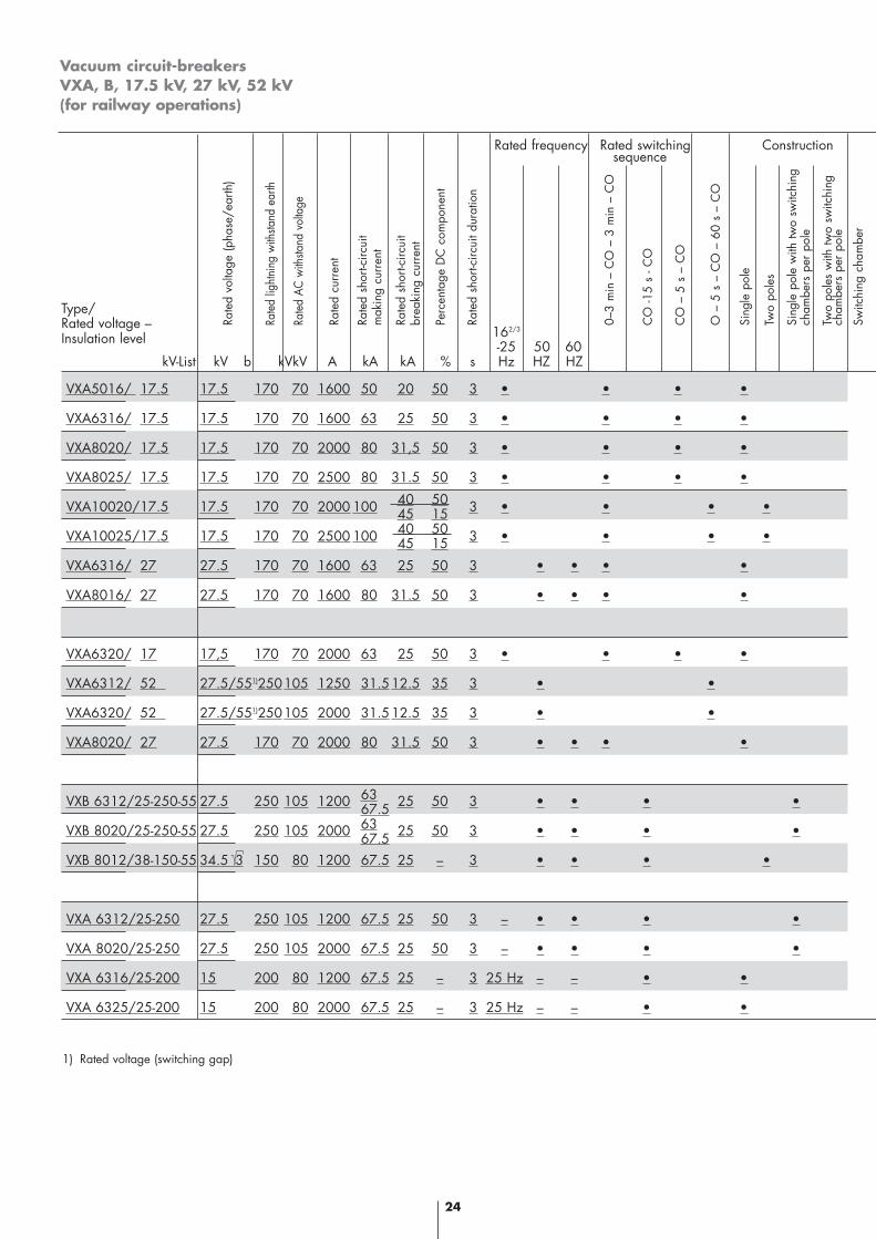
Vacuum circuit-breakersVXA, B, 17.5 kV, 27 kV, 52 kV(for railway operations)
24
VXA5016/ 17.5 17.5 170 70 1600 50 20 50 3 • • • •
VXA6316/ 17.5 17.5 170 70 1600 63 25 50 3 • • • •
VXA8020/ 17.5 17.5 170 70 2000 80 31,5 50 3 • • • •
VXA8025/ 17.5 17.5 170 70 2500 80 31.5 50 3 • • • •
40 50VXA10020/17.5 17.5 170 70 2000 100 45 15 3 • • • •
40 50VXA10025/17.5 17.5 170 70 2500 100 45 15 3 • • • •
VXA6316/ 27 27.5 170 70 1600 63 25 50 3 • • • •
VXA8016/ 27 27.5 170 70 1600 80 31.5 50 3 • • • •
VXA6320/ 17 17,5 170 70 2000 63 25 50 3 • • • •
VXA6312/ 52 27.5/551)250105 1250 31.512.5 35 3 • •
VXA6320/ 52 27.5/551)250105 2000 31.512.5 35 3 • •
VXA8020/ 27 27.5 170 70 2000 80 31.5 50 3 • • • •
VXB 6312/25-250-55 27.5 250 105 1200 63 25 50 3 • • • •67.5VXB 8020/25-250-55 27.5 250 105 2000 63 25 50 3 • • • •67.5VXB 8012/38-150-55 34.5 3 150 80 1200 67.5 25 – 3 • • • •
VXA 6312/25-250 27.5 250 105 1200 67.5 25 50 3 – • • • •
VXA 8020/25-250 27.5 250 105 2000 67.5 25 50 3 – • • • •
VXA 6316/25-200 15 200 80 1200 67.5 25 – 3 25 Hz – – • •
VXA 6325/25-200 15 200 80 2000 67.5 25 – 3 25 Hz – – • •
Rated frequency Rated switching Construction sequence
Type/Rated voltage –Insulation level 162/3
-25 50 60kV-List kV b kVkV A kA kA % s Hz HZ HZ
Rate
d vo
ltage
(pha
se/e
arth
)
Rate
d lig
htni
ng w
ithsta
nd e
arth
Rate
d AC
with
stand
vol
tage
Rate
d cu
rren
t
Rate
d sh
ort-c
ircui
t m
akin
g cu
rren
t
Rate
d sh
ort-c
ircui
tbr
eaki
ng c
urre
nt
Perc
enta
ge D
C c
ompo
nent
Rate
d sh
ort-c
ircui
t dur
atio
n
0–3
min
– C
O –
3 m
in –
CO
CO
-15
s - C
O
CO
– 5
s –
CO
O –
5 s
– C
O –
60
s –
CO
Sing
le p
ole
Two
pole
s
Sing
le p
ole
with
two
switc
hing
cham
bers
per
pol
e
Two
pole
s w
ith tw
o sw
itchi
ng
cham
bers
per
pol
e
Switc
hing
cha
mbe
r
1) Rated voltage (switching gap)
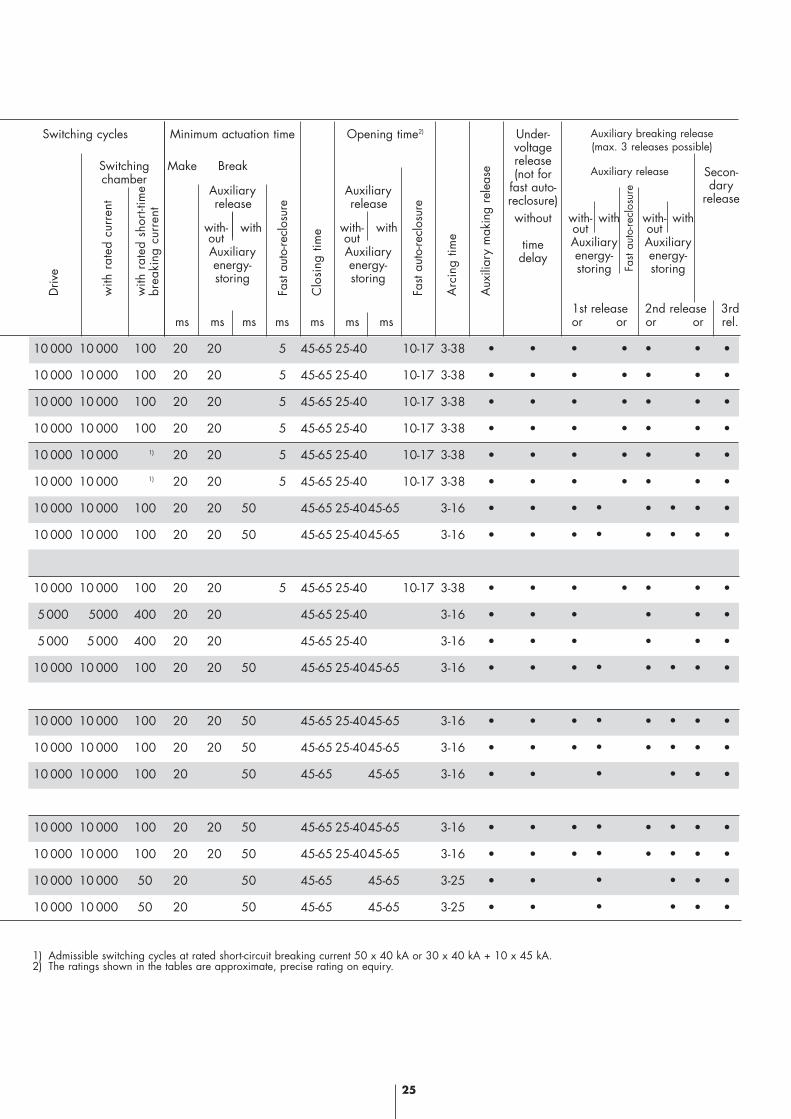
10 000 10 000 100 20 20 5 45-65 25-40 10-17 3-38 • • • • • • •
10 000 10 000 100 20 20 5 45-65 25-40 10-17 3-38 • • • • • • •
10 000 10 000 100 20 20 5 45-65 25-40 10-17 3-38 • • • • • • •
10 000 10 000 100 20 20 5 45-65 25-40 10-17 3-38 • • • • • • •
10 000 10 000 1) 20 20 5 45-65 25-40 10-17 3-38 • • • • • • •
10 000 10 000 1) 20 20 5 45-65 25-40 10-17 3-38 • • • • • • •
10 000 10 000 100 20 20 50 45-65 25-4045-65 3-16 • • • • • •
10 000 10 000 100 20 20 50 45-65 25-4045-65 3-16 • • • • • •
10 000 10 000 100 20 20 5 45-65 25-40 10-17 3-38 • • • • • • •
5000 5000 400 20 20 45-65 25-40 3-16 • • • • • •
5000 5000 400 20 20 45-65 25-40 3-16 • • • • • •
10 000 10 000 100 20 20 50 45-65 25-4045-65 3-16 • • • • • •
10 000 10 000 100 20 20 50 45-65 25-4045-65 3-16 • • • • • •
10 000 10 000 100 20 20 50 45-65 25-4045-65 3-16 • • • • • •
10 000 10 000 100 20 50 45-65 45-65 3-16 • • • •
10 000 10 000 100 20 20 50 45-65 25-4045-65 3-16 • • • • • •
10 000 10 000 100 20 20 50 45-65 25-4045-65 3-16 • • • • • •
10 000 10 000 50 20 50 45-65 45-65 3-25 • • • •
10 000 10 000 50 20 50 45-65 45-65 3-25 • • • •
1st release 2nd release 3rd ms ms ms ms ms ms ms or or or or rel.
Auxiliaryrelease
with- withoutAuxiliaryenergy-storing
Driv
e
with
rat
ed c
urre
nt
with
rat
ed s
hort-
time
brea
king
cur
rent
Fast
auto
-recl
osur
e
Clo
sing
tim
e
Fast
auto
-recl
osur
e
Arc
ing
time
Aux
iliar
y m
akin
g re
leas
e
Fast
aut
o-re
clos
ureAuxiliary
release
with- withoutAuxiliaryenergy-storing
1) Admissible switching cycles at rated short-circuit breaking current 50 x 40 kA or 30 x 40 kA + 10 x 45 kA.2) The ratings shown in the tables are approximate, precise rating on equiry.
Minimum actuation time Opening time2) Under-voltagerelease(not for
fast auto-reclosure)
Auxiliary release Secon-dary
release
Auxiliary breaking release(max. 3 releases possible)
without
timedelay
with- withoutAuxiliaryenergy-storing
with- withoutAuxiliaryenergy-storing
Make Break
Switching cycles
Switchingchamber
•
•
•
•
•
•
•
•
•
•
•
•
•
•
•
•
•
•
•
•
25
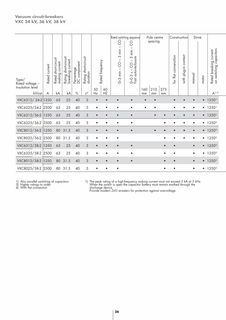
Vacuum circuit-breakersVXC 24 kV, 36 kV, 38 kV
26
VXC6312/ 24-2 1250 63 25 40 3 • • • • • • • • • • 12501)
VXC6325/24-2 2500 63 25 40 3 • • • • • • • • • • 12501)
VXC6312/36-2 1250 63 25 40 3 • • • • • • • • • • 12502)
VXC6325/36-2 2500 63 25 40 3 • • • • • • • • • 12502)
VXC8012/36-2 1250 80 31.5 40 3 • • • • • • • • • • 12502)
VXC8025/36-2 2500 80 31.5 40 3 • • • • • • • • 12502)
VXC6312/38-2 1250 63 25 40 3 • • • • • • • • 12502)
VXC6325/38-2 2500 63 25 40 3 • • • • • • • • 12502)
VXC8012/38-2 1250 80 31.5 40 3 • • • • • • • • 12502)
VXC8025/38-2 2500 80 31.5 40 3 • • • • • • • 12502)
Rated switching sequence Pole centre Construction Drivespacing
Type/Rated voltage –Insulation level 50 60 160 210 275
kV-List A kA kA % s4) Hz HZ mm mm mm A1) 2)
Rate
d cu
rren
t
Rate
d sh
ort-c
ircui
tm
akin
g cu
rren
t
Ratin
g sh
ort-c
ircui
tbr
eaki
ng c
urre
nt
Perc
enta
ge
D
C c
ompo
nent
Ratin
g sh
ort-c
ircui
t du
ratio
n
Rate
d fre
quen
cy
0–3
min
– C
O –
3 m
in –
CO
0–0.
3 s
– C
O –
3 m
in –
CO
Fast
auto
-recl
osur
e
for
flat c
onne
nctio
n
with
plu
g-in
con
tact
man
ual
mot
or
Rate
d br
eaki
ng c
urre
nton
sw
itchi
ng c
apac
itors
1) Also parallel switching of capacitors3) Higher ratings to order4) With flat connection
1) The peak rating of a high-frequency making current must not exceed 5 kA at 3 kHz.When the switch is open the capacitor battery must remain earthed through the discharge device.Provide modern ZnO arresters for protection against overvoltage.
with
rat
ed c
urre
nt
with
rat
ed s
hort-
circ
uit
brea
king
cur
rent
Clo
sing
tim
e1)
Arc
ing
time
Aux
iliar
y m
ake
rele
ase
27
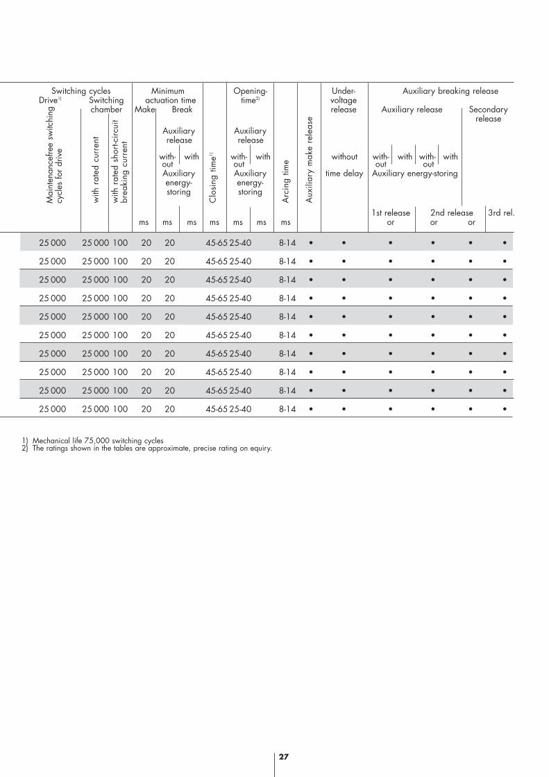
25 000 25 000 100 20 20 45-65 25-40 8-14 • • • • • •
25 000 25 000 100 20 20 45-65 25-40 8-14 • • • • • •
25 000 25 000 100 20 20 45-65 25-40 8-14 • • • • • •
25 000 25 000 100 20 20 45-65 25-40 8-14 • • • • • •
25 000 25 000 100 20 20 45-65 25-40 8-14 • • • • • •
25 000 25 000 100 20 20 45-65 25-40 8-14 • • • • • •
25 000 25 000 100 20 20 45-65 25-40 8-14 • • • • • •
25 000 25 000 100 20 20 45-65 25-40 8-14 • • • • • •
25 000 25 000 100 20 20 45-65 25-40 8-14 • • • • • •
25 000 25 000 100 20 20 45-65 25-40 8-14 • • • • • •
Switching cycles Minimum Opening- Under- Auxiliary breaking releaseDrive1) Switching actuation time time2) voltage
chamber Make Break release Auxiliary release Secondaryrelease
1st release 2nd release 3rd rel. ms ms ms ms ms ms ms or or or
Auxiliaryrelease
with- withoutAuxiliaryenergy-storing
Auxiliaryrelease
with- withoutAuxiliaryenergy-storing
without
time delay
with- with with- without out
Auxiliary energy-storing
Mai
nten
ance
free
switc
hing
cycl
es fo
r dr
ive
1) Mechanical life 75,000 switching cycles2) The ratings shown in the tables are approximate, precise rating on equiry.

28
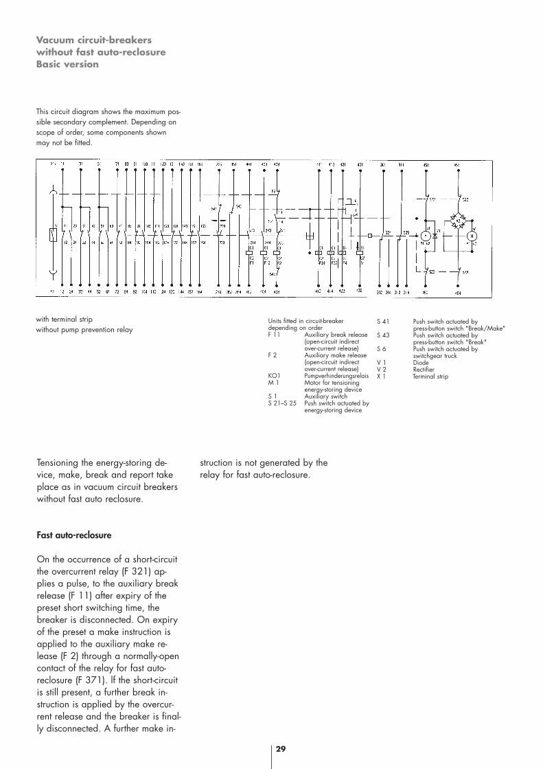
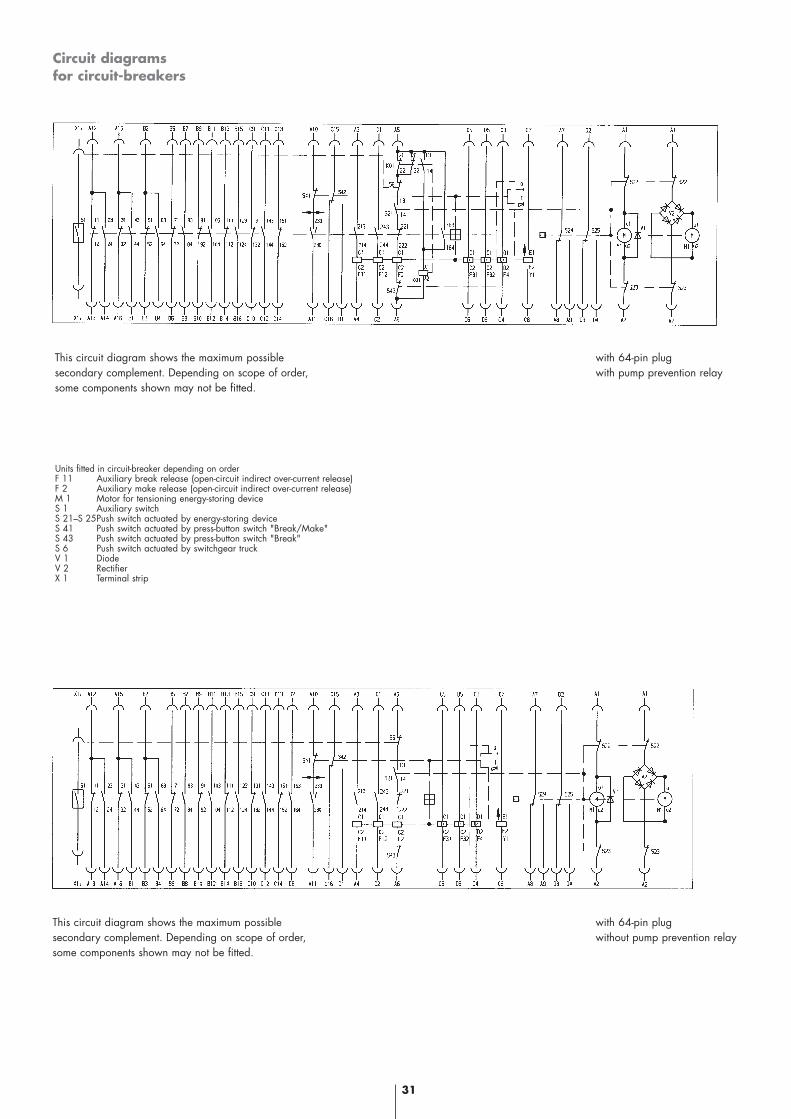
Vacuum circuit-breakerswithout fast auto-reclosureBasic version
This circuit diagram shows the maximum pos-sible secondary complement. Depending onscope of order, some components shownmay not be fitted.
with terminal strip with pump preventionrelay
Units fitted in circuit-breaker depending on orderF 11 Auxiliary break release (open-circuit indirect over-current release)F 2 Auxiliary make release (open-circuit indirect over-current release)M 1 Motor for tensioning energy-storing deviceS 1 Auxiliary switchS 21-S 25 Push switch actuated by energy-storing device
S 41 Push switch actuated by press-button switch "Break/Make"S 43 Push switch actuated by press-button switch "Break"S 6 Push switch actuated by switchgear truckV 1 DiodeV 2 RectifierX 1 Terminal strip
Tensioning the energy-storing device
By closing the switch (F 101) volt-age is applied to the motor (M) andthe energy-storing device is tension-ed. On completion of the tensioningprocess the push switches (S 22 and S 23) are actuated by ashaft and the motor is disconnected.
Making
Making takes place either (a) mechanically by means of thebutton "Make" or (b) electrically by means of thecontact element "Make" (SOE)which energises the auxiliary makerelease (F 2). Once the making process has beencompleted the motor tensions theenergy-storing device because the
push switches (S 22 and S 23) areclosed when the energy-storing de-vice is detensioned.
Breaking
Breaking takes place either (a) mechanically by means of thebutton "Break" or (b) electrically by means of thecontact element "Break" (SOA),which energises the auxiliary breakrelease (F 11) or (c) electrically byan overcurrent relay (F 321) whichenergises the auxiliary break relea-se (F 11)
Report
When the circuit-breaker is made,the report lamp "Make" (HOA)lights. When it is broken the report
lamp "Broken" (HOE) lights. Aswitching pulse is applied via thewiper contact (239/230) to therelay "Defecct" (KOS) by the auxil-iary switch in the circuit-breaker (S1) but only if actuation takes placeby means of the overcurrent relay (F321) because on manual actuationthe normally-closed contact of thepush switch (S 41) of the button"Break" is opened or, on electricalactuation, the normally-closedcontact of the switch element"Break" (SOA). The report relay"Defect" is equipped with a self-holding contact but may be deener-gised by its disconnection section(SOR). Voltage is applied to the re-port lamp (HOS) through the reportrelay "Defect".
Circuit diagrams
Vacuum circuit-breakerswithout fast auto-reclosureBasic version
This circuit diagram shows the maximum pos-sible secondary complement. Depending onscope of order, some components shownmay not be fitted.
29
Units fitted in circuit-breakerdepending on orderF 11 Auxiliary break release
(open-circuit indirectover-current release)
F 2 Auxiliary make release(open-circuit indirectover-current release)
KO1 PumpverhinderungsrelaisM 1 Motor for tensioning
energy-storing deviceS 1 Auxiliary switchS 21–S 25 Push switch actuated by
energy-storing device
with terminal strip without pump prevention relay
S 41 Push switch actuated bypress-button switch "Break/Make"
S 43 Push switch actuated bypress-button switch "Break"
S 6 Push switch actuated byswitchgear truck
V 1 DiodeV 2 RectifierX 1 Terminal strip
Tensioning the energy-storing de-vice, make, break and report takeplace as in vacuum circuit breakerswithout fast auto reclosure.
Fast auto-reclosure
On the occurrence of a short-circuitthe overcurrent relay (F 321) ap-plies a pulse, to the auxiliary breakrelease (F 11) after expiry of thepreset short switching time, thebreaker is disconnected. On expiryof the preset a make instruction isapplied to the auxiliary make re-lease (F 2) through a normally-opencontact of the relay for fast auto-reclosure (F 371). lf the short-circuitis still present, a further break in-struction is applied by the overcur-rent release and the breaker is final-ly disconnected. A further make in-
struction is not generated by therelay for fast auto-reclosure.
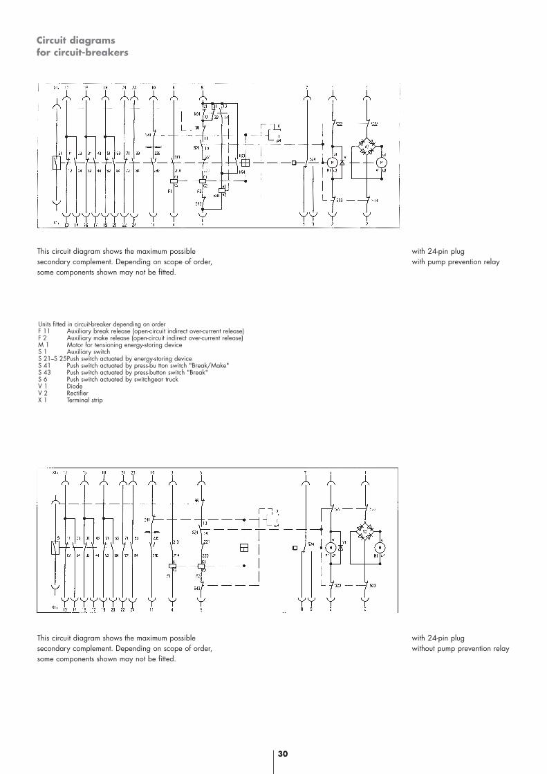
Circuit diagrams for circuit-breakers
30
This circuit diagram shows the maximum possible secondary complement. Depending on scope of order,some components shown may not be fitted.
with 24-pin plug with pump prevention relay
This circuit diagram shows the maximum possible secondary complement. Depending on scope of order,some components shown may not be fitted.
with 24-pin plug without pump prevention relay
Units fitted in circuit-breaker depending on orderF 11 Auxiliary break release (open-circuit indirect over-current release)F 2 Auxiliary make release (open-circuit indirect over-current release)M 1 Motor for tensioning energy-storing deviceS 1 Auxiliary switchS 21–S 25Push switch actuated by energy-storing deviceS 41 Push switch actuated by press-bu tton switch "Break/Make"S 43 Push switch actuated by press-button switch "Break"S 6 Push switch actuated by switchgear truckV 1 DiodeV 2 RectifierX 1 Terminal strip
Circuit diagrams for circuit-breakers
31
This circuit diagram shows the maximum possible secondary complement. Depending on scope of order,some components shown may not be fitted.
with 64-pin plug with pump prevention relay
This circuit diagram shows the maximum possible secondary complement. Depending on scope of order,some components shown may not be fitted.
with 64-pin plug without pump prevention relay
Units fitted in circuit-breaker depending on orderF 11 Auxiliary break release (open-circuit indirect over-current release)F 2 Auxiliary make release (open-circuit indirect over-current release)M 1 Motor for tensioning energy-storing deviceS 1 Auxiliary switchS 21–S 25Push switch actuated by energy-storing deviceS 41 Push switch actuated by press-button switch "Break/Make"S 43 Push switch actuated by press-button switch "Break"S 6 Push switch actuated by switchgear truckV 1 DiodeV 2 RectifierX 1 Terminal strip
32
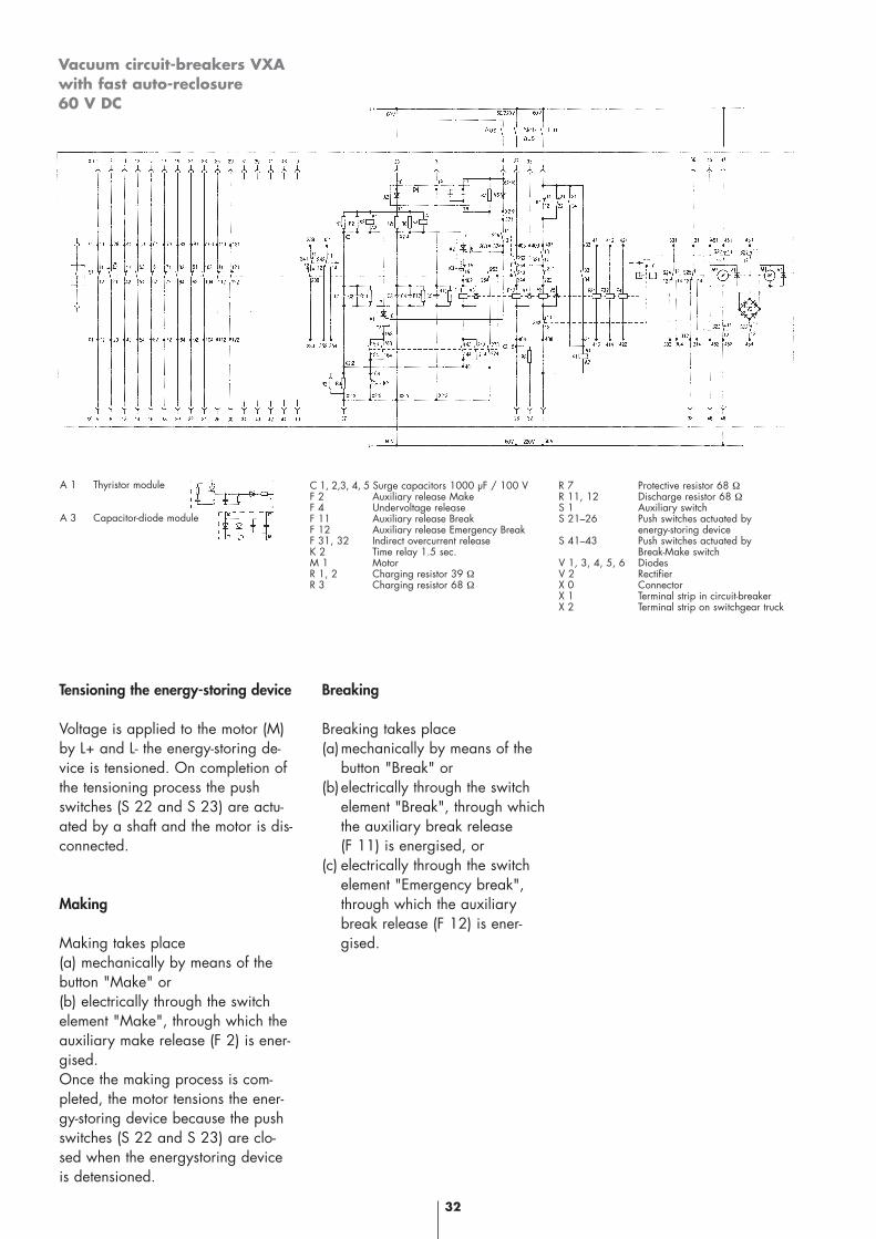
Vacuum circuit-breakers VXAwith fast auto-reclosure 60 V DC
C 1, 2,3, 4, 5 Surge capacitors 1000 µF / 100 VF 2 Auxiliary release MakeF 4 Undervoltage releaseF 11 Auxiliary release BreakF 12 Auxiliary release Emergency BreakF 31, 32 Indirect overcurrent releaseK 2 Time relay 1.5 sec.M 1 MotorR 1, 2 Charging resistor 39 ΩR 3 Charging resistor 68 Ω
R 7 Protective resistor 68 ΩR 11, 12 Discharge resistor 68 ΩS 1 Auxiliary switchS 21–26 Push switches actuated by
energy-storing deviceS 41–43 Push switches actuated by
Break-Make switchV 1, 3, 4, 5, 6 DiodesV 2 RectifierX 0 ConnectorX 1 Terminal strip in circuit-breakerX 2 Terminal strip on switchgear truck
A 1 Thyristor module
A 3 Capacitor-diode module
Tensioning the energy-storing device
Voltage is applied to the motor (M)by L+ and L- the energy-storing de-vice is tensioned. On completion ofthe tensioning process the pushswitches (S 22 and S 23) are actu-ated by a shaft and the motor is dis-connected.
Making
Making takes place (a) mechanically by means of thebutton "Make" or (b) electrically through the switchelement "Make", through which theauxiliary make release (F 2) is ener-gised. Once the making process is com-pleted, the motor tensions the ener-gy-storing device because the pushswitches (S 22 and S 23) are clo-sed when the energystoring deviceis detensioned.
Breaking
Breaking takes place(a)mechanically by means of the
button "Break" or(b)electrically through the switch
element "Break", through which the auxiliary break release (F 11) is energised, or
(c) electrically through the switch element "Emergency break", through which the auxiliary break release (F 12) is ener-gised.
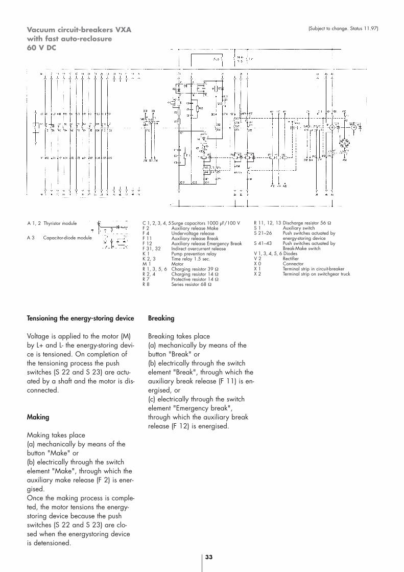
Vacuum circuit-breakers VXAwith fast auto-reclosure 60 V DC
33
(Subject to change. Status 11.97)
Tensioning the energy-storing device
Voltage is applied to the motor (M)by L+ and L- the energy-storing devi-ce is tensioned. On completion ofthe tensioning process the pushswitches (S 22 and S 23) are actu-ated by a shaft and the motor is dis-connected.
Making
Making takes place (a) mechanically by means of thebutton "Make" or (b) electrically through the switchelement "Make", through which theauxiliary make release (F 2) is ener-gised. Once the making process is comple-ted, the motor tensions the energy-storing device because the pushswitches (S 22 and S 23) are clo-sed when the energystoring deviceis detensioned.
Breaking
Breaking takes place(a) mechanically by means of thebutton "Break" or(b) electrically through the switchelement "Break", through which theauxiliary break release (F 11) is en-ergised, or(c) electrically through the switchelement "Emergency break",through which the auxiliary breakrelease (F 12) is energised.
A 1, 2 Thyristor module
A 3 Capacitor-diode module
C 1, 2, 3, 4, 5Surge capacitors 1000 µF/100 VF 2 Auxiliary release MakeF 4 Undervoltage releaseF 11 Auxiliary release BreakF 12 Auxiliary release Emergency BreakF 31, 32 Indirect overcurrent releaseK 1 Pump prevention relayK 2, 3 Time relay 1.5 sec.M 1 MotorR 1, 3, 5, 6 Charging resistor 39 ΩR 2, 4 Charging resistor 14 ΩR 7 Protective resistor 14 ΩR 8 Series resistor 68 Ω
R 11, 12, 13 Discharge resistor 56 ΩS 1 Auxiliary switchS 21–26 Push switches actuated by
energy-storing deviceS 41–43 Push switches actuated by
Break-Make switchV 1, 3, 4, 5, 6 DiodesV 2 RectifierX 0 ConnectorX 1 Terminal strip in circuit-breakerX 2 Terminal strip on switchgear truck
34
Vacuum tester VT 60
The dielectric strength of the brea-ker gap of the vacuum circuit-brea-ker may be tested using the vacuumtester VT 60. Indirectly a check is performed,whether or not the internal pressureof the switching chamber is ≤ 10-2
mbar. This tester allows checkingthe vacuum in the switching cham-ber complies with the requirements– in a simple and quick manner
without dismantling the switching device
– without a complicated test assembly
– with adequate accuracy
Special features
• Simple handling• Compact design (unit incl. case
approx. the size of a brief case)• Rugged construction• Light weight (approx. 8 kg)• Low capital outlay
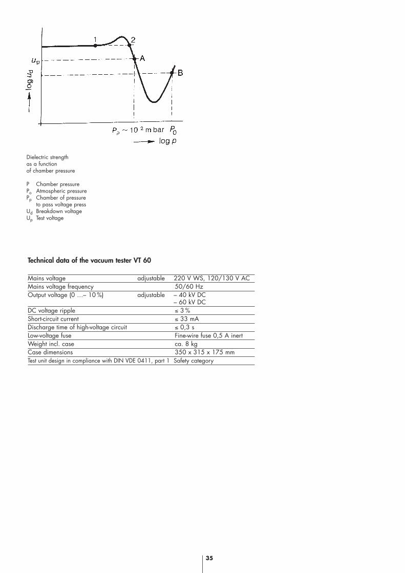
Physical principle of the test method
The dielectric strength of the vacu-um breaker gap is dependent onthe chamber pressure "P". Indirect checking of the vacuum isthus possible by means of a voltagemeasurement. The test point "A"
must be so situated that, on the onehand, there is sufficient space to testpoint "B" (condition when chamberfilled with air) and on the otherhand, so that the vacuum switchingchamber is not unnecessarily loa-ded.
Performance of the test
After connection of the vacuum te-ster VT 60 to the circuit-breaker tobe tested, the test is performed withsome few manipulations:1. Select test voltage (40 kV or
60 kV)2. Switch on mains switch,
red warning light shines “Caution high voltage"
3. At the same time turn rotary knobs "Test" with left and right hands in the direction shown bythe arrow to the stop and wait some seconds for the lamps to light up "Not defective" and"Defective". lf the green lamp lights (Not defective) the test has been completed, the vacuum chamber may be considered ser-viceable.
4. lf the red lamp lights, the test must be repeated twice.lf the green lamp does not light after the third attempt, the vacu-um chamber must be considereddefective.
The vacuum tester VT 60 thus allows
in simple manner the fast and reli-able testing of high-quality swit-ching devices.
Vacuum tester
35
Dielectric strengthas a functionof chamber pressure
P Chamber pressurePo Atmospheric pressurePp Chamber of pressure
to pass voltage pressUd Breakdown voltageUp Test voltage
Technical data of the vacuum tester VT 60
Mains voltage adjustable 220 V WS, 120/130 V ACMains voltage frequency 50/60 HzOutput voltage (0 …– 10 %) adjustable – 40 kV DC
– 60 kV DCDC voltage ripple ≤ 3 %Short-circuit current ≤ 33 mADischarge time of high-voltage circuit ≤ 0,3 sLow-voltage fuse Fine-wire fuse 0,5 A inertWeight incl. case ca. 8 kgCase dimensions 350 x 315 x 175 mmTest unit design in compliance with DIN VDE 0411, part 1 Safety category
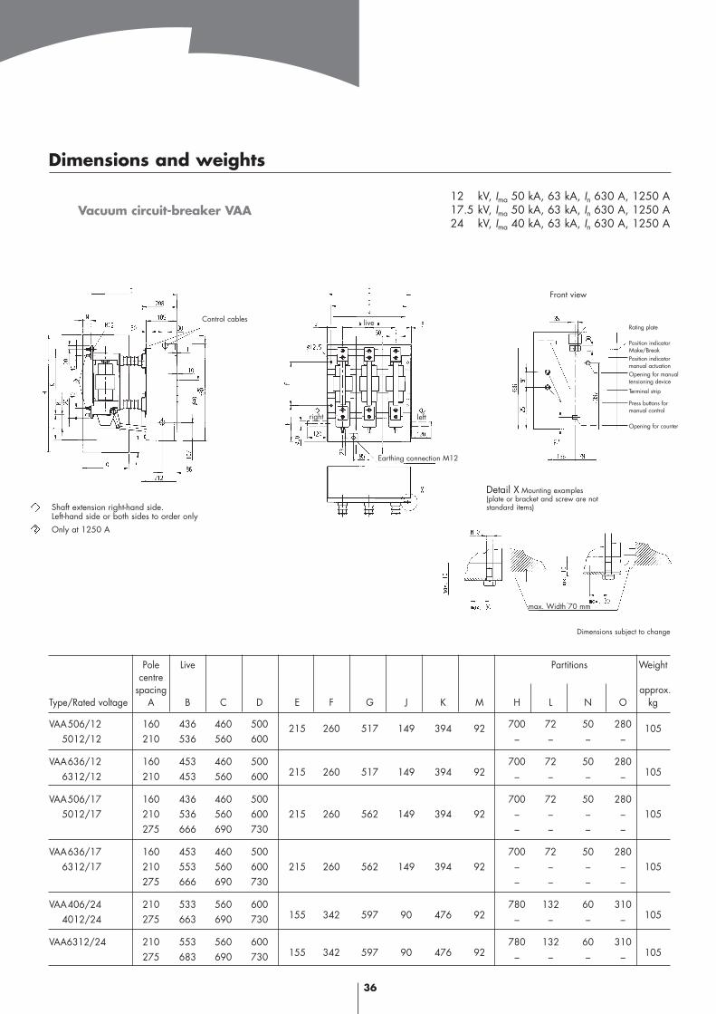
Vacuum circuit-breaker VAA
Pole Live Partitions Weightcentre
spacingType/Rated voltage A B C D E F G J K M H L N O kg
VAA506/12 160 436 460 500 215 260 517 149 394 92 700 72 50 280 1055012/12 210 536 560 600 – – – –
VAA636/12 160 453 460 500 700 72 50 2806312/12 210 453 560 600 215 260 517 149 394 92 – – – – 105
VAA506/17 160 436 460 500 700 72 50 2805012/17 210 536 560 600 215 260 562 149 394 92 – – – – 105
275 666 690 730 – – – –
VAA636/17 160 453 460 500 700 72 50 2806312/17 210 553 560 600 215 260 562 149 394 92 – – – – 105
275 666 690 730 – – – –
VAA406/24 210 533 560 600 780 132 60 3104012/24 275 663 690 730 155 342 597 90 476 92 – – – – 105
VAA6312/24 210 553 560 600 780 132 60 310275 683 690 730 155 342 597 90 476 92 – – – – 105
36
12 kV, Ima 50 kA, 63 kA, In 630 A, 1250 A17.5 kV, Ima 50 kA, 63 kA, In 630 A, 1250 A24 kV, Ima 40 kA, 63 kA, In 630 A, 1250 A
Dimensions and weights
Shaft extension right-hand side.Left-hand side or both sides to order onlyOnly at 1250 A
Control cables live
left
Earthing connection M12
right
Front view
Rating plate
Position indicatorMake/BreakPosition indicatormanual actuationOpening for manualtensioning device
Terminal strip
Press buttons for manual control
Opening for counter
Detail X Mounting examples(plate or bracket and screw are not standard items)
max. Width 70 mm
Dimensions subject to change
approx.
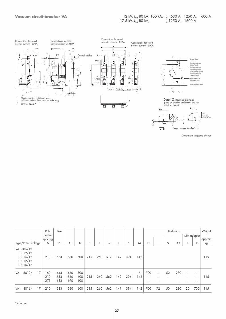
Vacuum circuit-breaker VA
Pole Live Partitions Weightcentre
spacingType/Rated voltage A B C D E F G J K M H L N O P R kg
VA 806/128012/128016/12 210 553 560 600 215 260 517 149 394 142 115
10012/1210016/12
VA 8012/ 17 160 443 460 500 * 700 – 50 280 – –210 533 560 600 215 260 562 149 394 142 – – – – – – 115275 683 690 600 – – – – – –
VA 8016/ 17 210 533 560 600 215 260 562 149 394 142 700 72 50 280 20 700 115
37
12 kV, Ima 80 kA, 100 kA, In 630 A, 1250 A, 1600 A17.5 kV, Ima 80 kA, In 1250 A, 1600 A,
*to order
approx.
Rating plate
Position indicatorMake/BreakPosition indicatormanual actuationOpening for manualtensioning device
Terminal strip
Press buttons for manual control
Opening for counter
Shaft extension right-hand side.Left-hand side or both sides to order onlyOnly at 1250 A
Detail X Mounting examples(plate or bracket and screw are not standard items)
live
right left
Earthing connection M12
Connections for ratednormal current ≤1250A Connections for rated
normal current 1600A
Connections for ratednormal current ≤1250A
Control cables
Connections for ratednormal current 1600A
max. Width 70 mm
Dimensions subject to change
with adapter
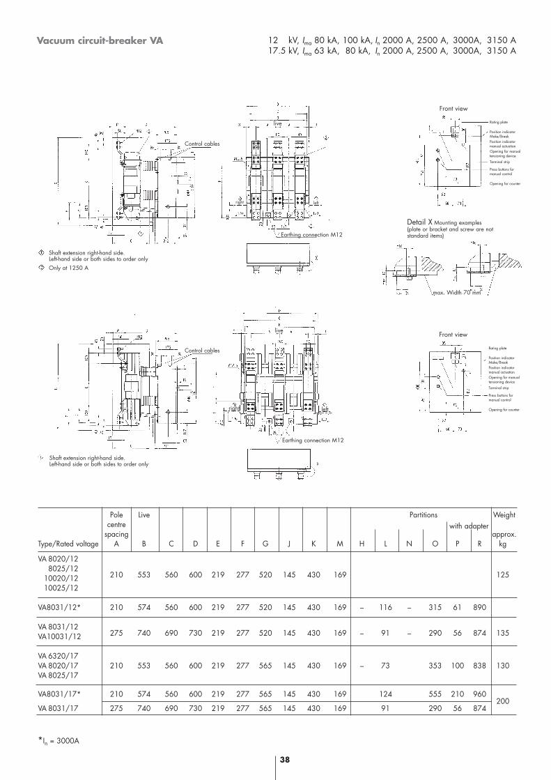
Vacuum circuit-breaker VA
38
12 kV, Ima 80 kA, 100 kA, In 2000 A, 2500 A, 3000A, 3150 A17.5 kV, Ima 63 kA, 80 kA, In 2000 A, 2500 A, 3000A, 3150 A
Pole Live Partitions Weightcentre
spacingType/Rated voltage A B C D E F G J K M H L N O P R kg
VA 8020/128025/12
10020/12 210 553 560 600 219 277 520 145 430 169 125
10025/12
VA8031/12* 210 574 560 600 219 277 520 145 430 169 – 116 – 315 61 890
VA 8031/12VA10031/12 275 740 690 730 219 277 520 145 430 169 – 91 – 290 56 874 135
VA 6320/17VA 8020/17 210 553 560 600 219 277 565 145 430 169 – 73 353 100 838 130VA 8025/17
VA8031/17* 210 574 560 600 219 277 565 145 430 169 124 555 210 960
VA 8031/17 275 740 690 730 219 277 565 145 430 169 91 290 56 874200
*In = 3000A
Shaft extension right-hand side.Left-hand side or both sides to order onlyOnly at 1250 A
Control cables
Shaft extension right-hand side.Left-hand side or both sides to order only
Control cables
Earthing connection M12
Earthing connection M12
right left
live
Rating plate
Position indicatorMake/BreakPosition indicatormanual actuationOpening for manualtensioning device
Terminal strip
Press buttons for manual control
Opening for counter
Detail X Mounting examples(plate or bracket and screw are not standard items)
max. Width 70 mm
Front view
Front view
Rating plate
Position indicatorMake/BreakPosition indicatormanual actuationOpening for manualtensioning device
Terminal strip
Press buttons for manual control
Opening for counter
approx.with adapter
live
right left
39
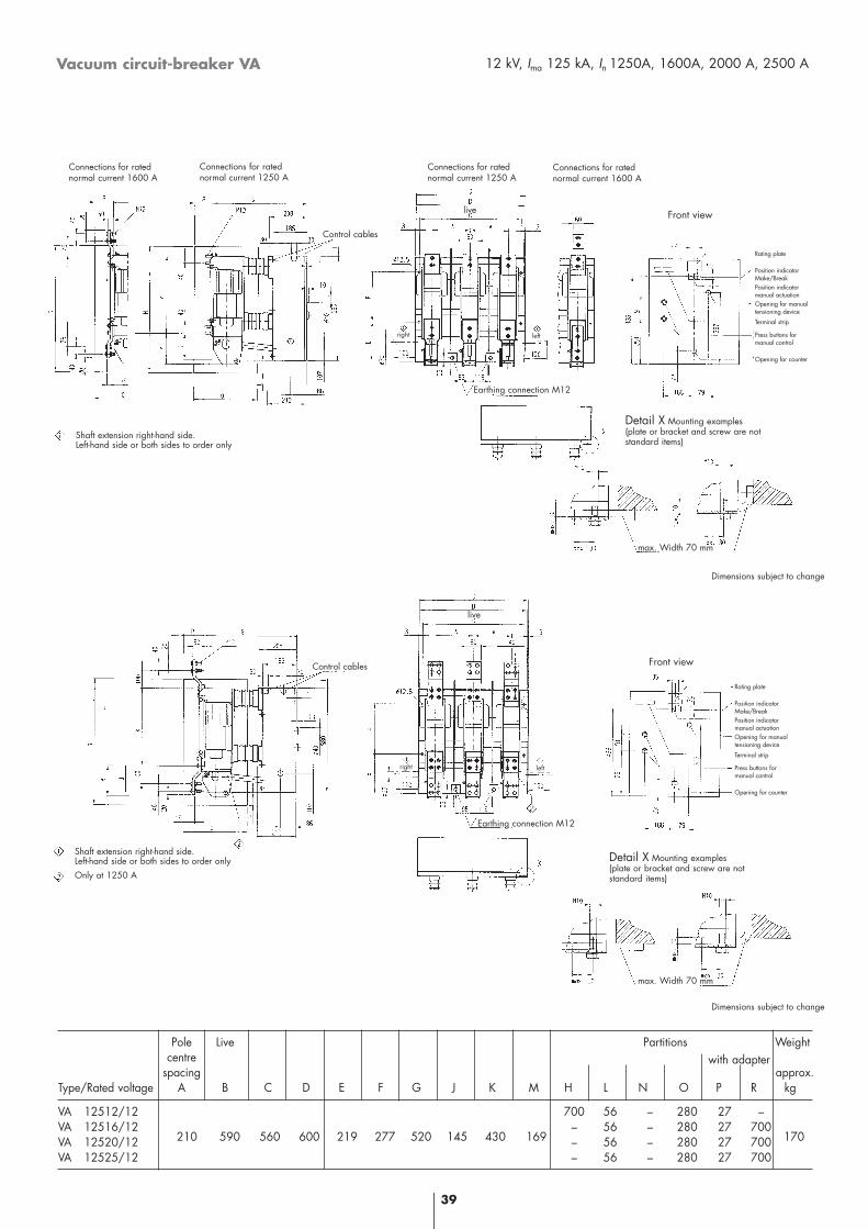
Vacuum circuit-breaker VA 12 kV, Ima 125 kA, In 1250A, 1600A, 2000 A, 2500 A
Pole Live Partitions Weightcentre
spacingType/Rated voltage A B C D E F G J K M H L N O P R kg
VA 12512/12 700 56 – 280 27 –VA 12516/12 – 56 – 280 27 700VA 12520/12 210 590 560 600 219 277 520 145 430 169 – 56 – 280 27 700 170
VA 12525/12 – 56 – 280 27 700
approx.with adapter
Shaft extension right-hand side.Left-hand side or both sides to order onlyOnly at 1250 A
Shaft extension right-hand side.Left-hand side or both sides to order only
Detail X Mounting examples(plate or bracket and screw are not standard items)
Detail X Mounting examples(plate or bracket and screw are not standard items)
Front view
Front view
Rating plate
Position indicatorMake/BreakPosition indicatormanual actuationOpening for manualtensioning device
Terminal strip
Press buttons for manual control
Opening for counter
Connections for ratednormal current 1250 A
Connections for ratednormal current 1600 A
Connections for ratednormal current 1250 A
Connections for ratednormal current 1600 A
Dimensions subject to change
Dimensions subject to change
Rating plate
Position indicatorMake/BreakPosition indicatormanual actuationOpening for manualtensioning device
Terminal strip
Press buttons for manual control
Opening for counter
max. Width 70 mm
Control cables
Earthing connection M12
live
right left
Control cables
Earthing connection M12
live
right left
max. Width 70 mm
40
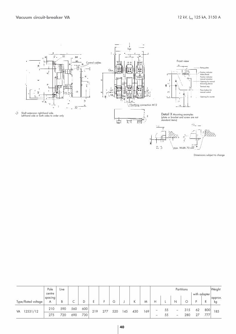
Vacuum circuit-breaker VA 12 kV, Ima 125 kA, 3150 A
Pole Live Partitions Weightcentre
spacingType/Rated voltage A B C D E F G J K M H L N O P R kg
VA 12531/12210 590 560 600
219 277 520 145 430 169 – 55 – 315 62 800 185275 720 690 730 – 55 – 280 27 777
Shaft extension right-hand side.Left-hand side or both sides to order only
Control cables
live
leftright
Earthing connection M12
Front view
Rating plate
Position indicatorMake/BreakPosition indicatormanual actuationOpening for manualtensioning device
Terminal strip
Press buttons for manual control
Opening for counter
Detail X Mounting examples(plate or bracket and screw are not standard items)
Dimensions subject to change
max. Width 70 mm
approx.with adapter
41
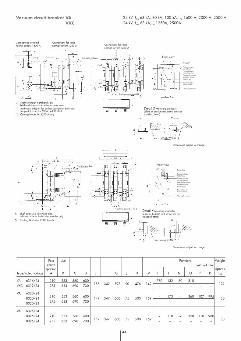
Vacuum circuit-breaker VAVXC
24 kV, Ima 63 kA, 80 kA, 100 kA, In 1600 A, 2000 A, 2500 A24 kV, Ima 63 kA, In 1250A, 2500A
Pole Live Partitions Weightcentre
spacingType/Rated voltage A B C D E F G J K M H L N O P R kg
VA 6316/24 210 553 560 600 780 132 60 310 – –VXC 6312/24 275 683 690 730 155 342 597 90 476 142 – – – – – – 122
VA 6320/248020/24 210 553 560 600 149 347 600 75 500 169 – 173 – 360 107 995 130
10020/24 275 683 690 730 – – – – – –
VA 6325/248025/24 210 553 560 600 – 110 – 390 110 980
10025/24 275 683 690 730 149 347 600 75 500 169 – – – – – – 130
Detail X Mounting examples(plate or bracket and screw are not standard items)
Detail X Mounting examples(plate or bracket and screw are not standard items)
Shaft extension right-hand side.Left-hand side or both sides to order onlyAdditional adapter for busbar connection both endsTo special order for 630A and 1250 ACooling blocks for 2500 A only
Connections for ratednormal current 1600 A
Dimensions subject to change
Dimensions subject to change
Earthing connection M12
Earthing connection M12
Connections for ratednormal current 1250 A
Connections for ratednormal current 1250 A
Front view
Rating plate
Position indicatorMake/BreakPosition indicatormanual actuationOpening for manualtensioning device
Terminal strip
Press buttons for manual control
Opening for counter
Control cables
right left
Shaft extension right-hand side.Left-hand side or both sides to order onlyCooling blocks for 2500 A only
Front view
Rating plate
Position indicatorMake/BreakPosition indicatormanual actuationOpening for manualtensioning device
Terminal strip
Press buttons for manual control
Opening for counter
rightleft
max. Width 70 mm
max. Width 70 mm
approx.with adapter
live
live
live
Control cables
42
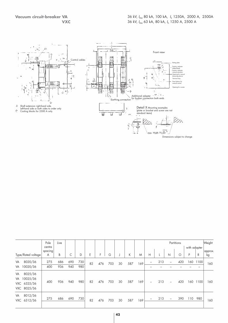
Vacuum circuit-breaker VAVXC
36 kV, Ima 80 kA, 100 kA, In 1250A, 2000 A, 2500A36 kV, Ima 63 kA, 80 kA, In 1250 A, 2500 A
Pole Live Partitions Weightcentre
spacingType/Rated voltage A B C D E F G J K M H L N O P R kg
VA 8020/36 275 686 690 730 82 476 703 30 587 169 – 213 – 420 160 1100 160VA 10020/36 400 936 940 980 – – – – – –
VA 8025/36VA 10025/36VXC 6325/36 400 936 940 980 82 476 703 30 587 169 – 213 – 420 160 1100 160
VXC 8025/36
VA 8012/36VXC 6312/36 275 686 690 730 82 476 703 30 587 169 – 213 – 390 110 980 160
approx.with adapter
Shaft extension right-hand side.Left-hand side or both sides to order onlyCooling blocks for 2500 A only
Control cables
leftright
Front view
Rating plate
Position indicatorMake/BreakPosition indicatormanual actuationOpening for manualtensioning device
Terminal strip
Press buttons for manual control
Opening for counter
Detail X Mounting examples(plate or bracket and screw are not standard items)
live
Earthing connection Additional adapter for busbar connection both ends
max. Width 70 mm
Dimensions subject to change
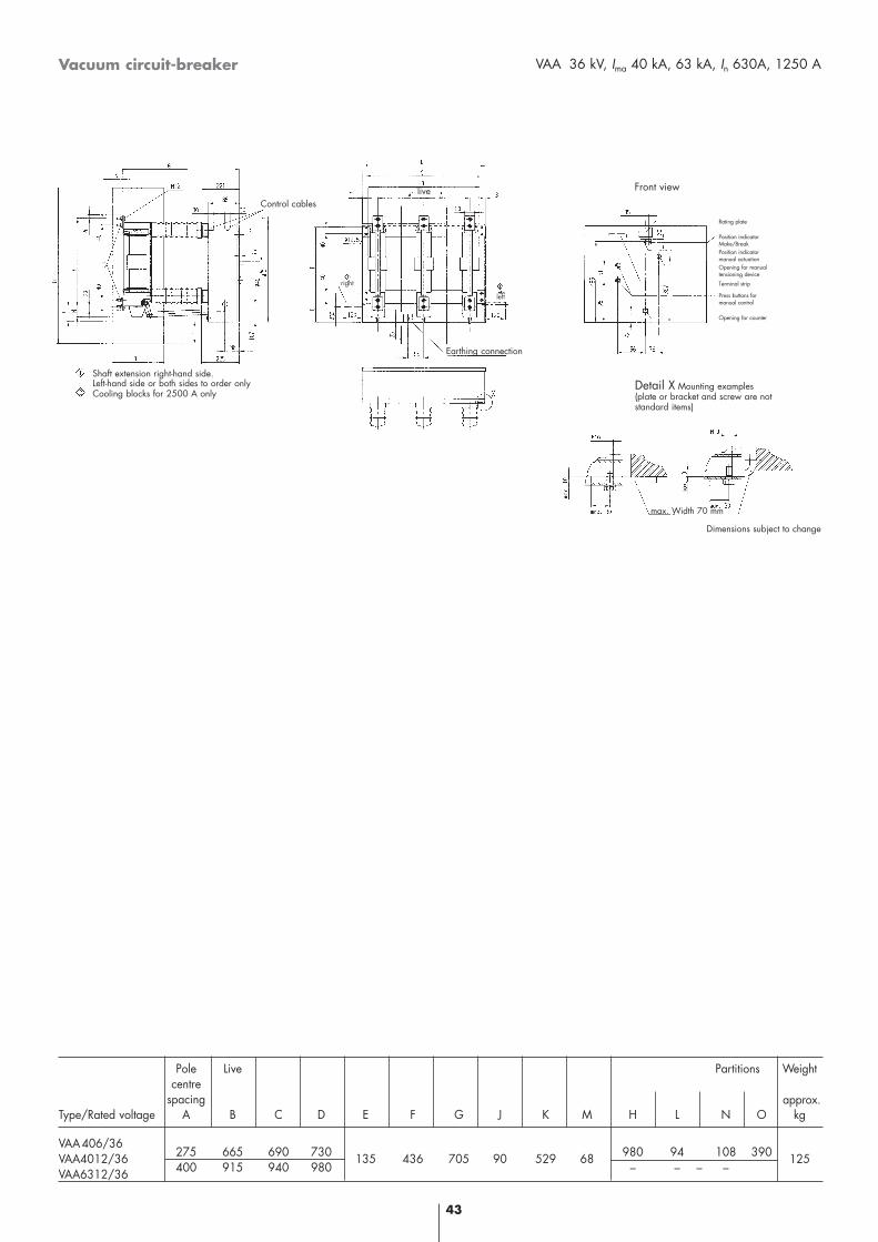
Vacuum circuit-breaker VAA 36 kV, Ima 40 kA, 63 kA, In 630A, 1250 A
Pole Live Partitions Weightcentre
spacingType/Rated voltage A B C D E F G J K M H L N O kg
VAA406/36VAA4012/36 275 665 690 730 135 436 705 90 529 68 980 94 108 390 125VAA6312/36 400 915 940 980 – – – –
approx.
Shaft extension right-hand side.Left-hand side or both sides to order onlyCooling blocks for 2500 A only
Control cables
left
Front view
Rating plate
Position indicatorMake/BreakPosition indicatormanual actuationOpening for manualtensioning device
Terminal strip
Press buttons for manual control
Opening for counter
Detail X Mounting examples(plate or bracket and screw are not standard items)
live
Dimensions subject to change
right
Earthing connection
max. Width 70 mm
43
44
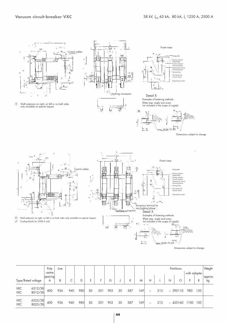
Vacuum circuit-breaker VXC
Pole Live Partitions Weightcentre
spacingType/Rated voltage A B C D E F G J K M H L N O P R kg
VXC 6312/38VXC 8012/38 400 936 940 980 82 501 903 30 587 169 – 213 – 390110 980 150
VXC 6325/38VXC 8025/38 400 936 940 980 82 501 903 30 587 169 – 213 – 420160 1100 150
38 kV, Ima 63 kA, 80 kA, In 1250 A, 2500 A
approx.with adapter
Front view
Rating plate
Position indicatorMake/BreakPosition indicatormanual actuationOpening for manualtensioning device
Terminal strip
Press buttons for manual control
Opening for counter
Detail XExamples of fastening methods(Plate resp. angle and screw not included in the scape of supply)
Front view
Rating plate
Position indicatorMake/BreakPosition indicatormanual actuationOpening for manualtensioning device
Terminal strip
Press buttons for manual control
Opening for counter
Detail XExamples of fastening methods(Plate resp. angle and screw not included in the scape of supply)
Shaft extension on right, on left or on both sidesonly available on special request
Dimensions subject to change
Earthing connection
Control cables
leftright
max. Width 70 mm
Earthing connection
Shaft extension on right, on left or on both sides only available on special requestCooling blocks for 2500 A only
live
leftright
Dimensions subject to change
max. Width 70 mm
Accessory terminal fortwo busbars/phase
Control cables
live
45
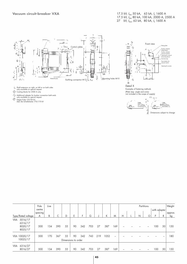
Vacuum circuit-breaker VXA 17.5 kV, Ima 50 kA, 63 kA, In 1600 A17.5 kV, Ima 80 kA, 100 kA, 2000 A, 2500 A27 kV, Ima, 63 kA, 80 kA, In 1600 A
Pole Live Partitions Weightcentre
spacingType/Rated voltage A B C D E F G J K M H L N O P R kgVXA 5016/17
6316/178020/17 500 134 390 55 90 342 703 27 587 169 – – – – 100 50 1508025/17
VXA 10020/17 500 170 367 55 90 342 743 219 1052 – – – – – – – 18010025/17
VXA 6316/278016/27 500 134 390 55 90 342 703 27 587 169 – – – – 100 50 150
Dimensions to order
Mounting holes M10Earthing connection M12
Shaft extension on right, on left or on both sides only available on special requestCooling blocks for 2500 A only
Additional adapter for busbar connection both ends only available on special requestGegen Erde 125/50 kV, über die Schaltstrecke 170/170 kV
Abdeckhaube
Rating plate
Position indicatorMake/BreakPosition indicatormanual actuationOpening for manualtensioning device
Terminal strip
Press buttons for manual control
Opening for counter
Front view
leftright
Detail XExamples of fastening methods(Plate resp. angle and screw not included in the scape of supply)
Dimensions subject to change
Control cables
approx.with adapter
live
rightleft
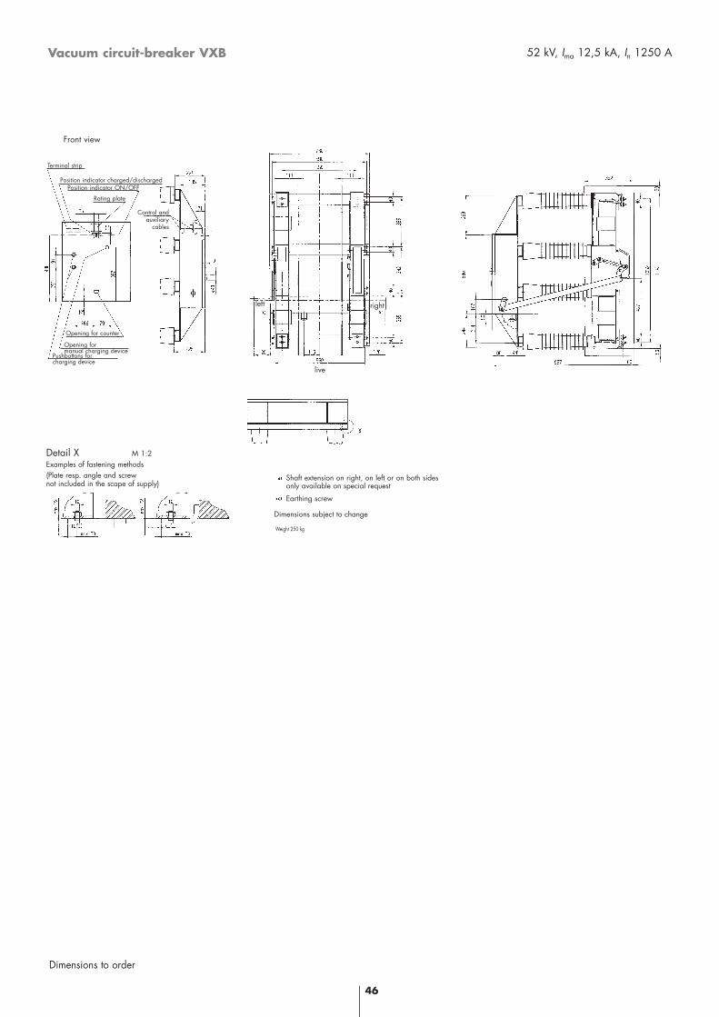
Terminal strip
46
Vacuum circuit-breaker VXB 52 kV, Ima 12,5 kA, In 1250 A
Dimensions to order
Weight 250 kg
Detail X M 1:2 Examples of fastening methods(Plate resp. angle and screw not included in the scape of supply)
live
Pushbottons forcharging device
Opening for manual charging device
Opening for counter
Position indicator ON/OFF
Rating plate
Control and auxiliary
cables
Dimensions subject to change
rightleft
Shaft extension on right, on left or on both sidesonly available on special request
Earthing screw
Front view
Position indicator charged/discharged
T&
D/B
PRO
B/M
VS-
CB
VA
/eng
/MV
B/0
2.03
/DE
/405
3/©
ALS
TO
M 2
003/
Con
cept
und
Cre
atio
n:SC
HR
EM
L W
erbe
agen
tur
SW
.06.
05/0
203
E
www.tde.alstom.com
South East AsiaTel.: +65 67 49 07 77 - Fax: +65 68 41 95 55
PacificTel.: +65 67 49 07 77 - Fax: +65 68 46 17 95
ChinaTel.: +86 10 64 10 62 88 - Fax: +86 10 64 10 62 64
IndiaTel.: +91 11 64 49 907 - Fax: +91 11 64 49 447
North AmericaTel.: +1 (484) 766-8100 - Fax: +1 (484) 766-8120
Central AmericaTel.: +52 55 11 01 07 00 - Fax: +52 55 26 24 04 93
South AmericaTel.: +55 11 30 69 08 01 - Fax: +55 11 30 69 07 93
FranceTel.: +33 1 40 89 66 00 - Fax: +33 1 40 89 67 19
British IslesTel.: +44 17 85 27 41 08 - Fax: +44 17 85 27 45 74
Northern EuropeTel.: +49 69 66 32 11 51 - Fax: +49 69 66 32 21 54
Central Europe & Western AsiaTel.: +48 22 850 96 00 - Fax: +48 22 654 55 90
Near & Middle EastTel.: +971 6 556 3971 - Fax: +971 6 556 5133
Mediterranean, North & West AfricaTel.: +33 1 41 49 20 00 - Fax: +33 1 41 49 24 23
Southern & Eastern AfricaTel.: +27 11 82 05 111 - Fax: +27 11 82 05 220