meeting 3 - eecs · meeting 3 summer 2009 doing ... converting between binary and hexadecimal is...
TRANSCRIPT
Meeting 3
Summer 2009 Doing DSP Workshop
Today:
◮ Positives and negatives.
◮ Addition and subtraction.
◮ Multiplication and bit growth.
◮ Saturation and discarding.
The numbers may be said to rule the whole world of quantity, and the four rules
of arithmetic may be regarded as the complete equipment of the mathematician.
— James C. Maxwell
Doing DSP Workshop – Summer 2009 Meeting 3 – Page 1/70 Tuesday – May 12, 2009
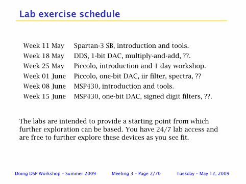
Lab exercise schedule
Week 11 May Spartan-3 SB, introduction and tools.
Week 18 May DDS, 1-bit DAC, multiply-and-add, ??.
Week 25 May Piccolo, introduction and 1 day workshop.
Week 01 June Piccolo, one-bit DAC, iir filter, spectra, ??
Week 08 June MSP430, introduction and tools.
Week 15 June MSP430, one-bit DAC, signed digit filters, ??.
The labs are intended to provide a starting point from which
further exploration can be based. You have 24/7 lab access and
are free to further explore these devices as you see fit.
Doing DSP Workshop – Summer 2009 Meeting 3 – Page 2/70 Tuesday – May 12, 2009
Computer numbers and arithmetic
Working at setting the stage for fixed point arithmetic:
◮ at the Spartan-3 logic level,
◮ at the Piccolo/MSP430 assembly level,
◮ at the Piccolo/MSP430 C level.
Have most control/responsibility at the logic level and the least
at the C level.
If you start with the basics it should be clear what is being done
at the C level. If you start at the C level, well, things are
probably much less clear.
Doing DSP Workshop – Summer 2009 Meeting 3 – Page 3/70 Tuesday – May 12, 2009
Some modern references
Computer Arithmetic Algorithms and Hardware Designs, B. Parhami
(2nd edition is planned for 2010). See
www.ece.ucsb.edu/~parhami/text_comp_arit.htm .
Computer Arithmetic Algorithms, 2nd ed, I. Koren.
Synthesis of Arithmetic Circuits, FPGA, ASIC and Embedded Systems, J.
Deschamps, G. Bioul and G. Sutter.
Digital-Serial Computation, R. Harley and K. Parhi.
Elementary Functions Algorithms and Implementation, 2nd ed, J.
Muller.
For methods of implementation I’ve also been looking at (and using)
old journal article/letters. Implementations often aren’t thought
about until there is a need to accomplish a task.
Doing DSP Workshop – Summer 2009 Meeting 3 – Page 4/70 Tuesday – May 12, 2009
Overview
◮ We have been spoiled by tools like MATLAB which use 64-big
floating point and (thankfully) hide the details of computation
from us.
◮ Most embedded processors use far fewer bits and do not natively
support floating point. We need to know how to work with
numbers and get valid results.
◮ Today’s discussion looks at number representations, unsigned,
signed, fractional. Properties of addition and multiplication.
◮ The two main concerns are that partial/end results might be too
large for the word size used (overflow) and that when discarding
least significant bits values need to be rounded, properly.
◮ A recent EECS 452 corporate project was almost entirely focused
on proper (whatever that means) saturation and rounding when
implementing fixed point IIR filters.
Doing DSP Workshop – Summer 2009 Meeting 3 – Page 5/70 Tuesday – May 12, 2009
Fixed point numbers
Key concepts to be looked at:
◮ Positional notation.
◮ Decimal (radix-10) notation.
◮ Decimal fractions.
◮ Negative numbers.
◮ Binary (radix-2) representation.
◮ Hexadecimal (radix-16) representation.
◮ Scientific notation (value and radix to a power).
Doing DSP Workshop – Summer 2009 Meeting 3 – Page 6/70 Tuesday – May 12, 2009
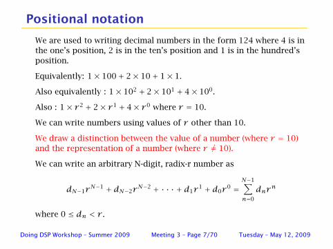
Positional notation
We are used to writing decimal numbers in the form 124 where 4 is in
the one’s position, 2 is in the ten’s position and 1 is in the hundred’s
position.
Equivalently: 1× 100+ 2× 10+ 1× 1.
Also equivalently : 1× 10² + 2× 101 + 4× 100.
Also : 1× r 2 + 2× r 1 + 4× r 0 where r = 10.
We can write numbers using values of r other than 10.
We draw a distinction between the value of a number (where r = 10)
and the representation of a number (where r 6= 10).
We can write an arbitrary N-digit, radix-r number as
dN−1rN−1 + dN−2r
N−2 + · · · + d1r1 + d0r
0 =
N−1∑
n=0
dnrn
where 0 ≤ dn < r .
Doing DSP Workshop – Summer 2009 Meeting 3 – Page 7/70 Tuesday – May 12, 2009
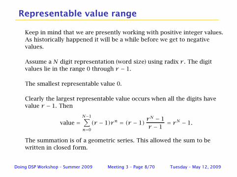
Representable value range
Keep in mind that we are presently working with positive integer values.
As historically happened it will be a while before we get to negative
values.
Assume a N digit representation (word size) using radix r . The digit
values lie in the range 0 through r − 1.
The smallest representable value 0.
Clearly the largest representable value occurs when all the digits have
value r − 1. Then
value =
N−1∑
n=0
(r − 1)rn = (r − 1)rN − 1
r − 1= rN − 1.
The summation is of a geometric series. This allowed the sum to be
written in closed form.
Doing DSP Workshop – Summer 2009 Meeting 3 – Page 8/70 Tuesday – May 12, 2009
Common radix values
If given a pattern such as 1011 we also need to know the value
of r in order to determine the associated value.
r is referred to as the radix or number base.
When working with computers radix values of 2 and 16 are
commonly used.
Radix equal 2 values use digit values 0 and 1 and are said to be
written in binary.
Radix equal 16 values use digit values 0, 1, 2, 3, 4, 5, 6, 7, 8, 9,
A, B, C, D, E, F. Radix 16 numbers are said to be written in
hexadecimal.
Doing DSP Workshop – Summer 2009 Meeting 3 – Page 9/70 Tuesday – May 12, 2009
Alternative representations exist
There exist other ways of writing numbers (representing values).
For example:
◮ Roman numerals.
◮ As time is written with a mix of seconds, minutes, hours,
days, etc.
◮ Residue number system.
◮ Dual base.
◮ Signed digit.
Doing DSP Workshop – Summer 2009 Meeting 3 – Page 10/70 Tuesday – May 12, 2009

Converting between representations
Converting between binary and hexadecimal is easy.
To convert binary to hexadecimal group the binary digits (bits)
into groups of four bits and replace the groups with the
associated hexadecimal digit.
For example 0001 1111 0101 becomes 1F5.
To convert hexadecimal to binary simply replace each
hexadecimal digit with it’s associated binary bit pattern.
For example C42 becomes 1100 0100 0010.
Converting between other radices or other representations
generally takes more effort.
Doing DSP Workshop – Summer 2009 Meeting 3 – Page 11/70 Tuesday – May 12, 2009
Keeping track of the radix value
When type setting use a subscript. For example: 12316.
If no subscript is present it is generally safe to assume base 10.
C has a number of ways:
◮ For hexadecimal: 0x123
◮ For octal 0123
◮ other
Sometimes hexadecimal is written: 123h. Generally need to
prefix using a leading 0 to help out the parser: 0F23h.
Sometimes binary is simply assumed. Sometimes a trailing b is
appended: 10011b.
Sometimes one has to figure out what radix is being used by
context.
Doing DSP Workshop – Summer 2009 Meeting 3 – Page 12/70 Tuesday – May 12, 2009
Fractions
When we (in the US) write a value like 123.4 the period indicates
an integer part and a fractional part. For this example we have
1× 10² + 2× 101 + 3× 100 + 4× 10⁻¹.
The . separates the non-negative (positive?) powers of 10 and
the negative powers of 10.
For the above example the . is called the decimal point.
In more general terms it is referred to as the radix point.
For binary numbers it is termed the binary point.
Doing DSP Workshop – Summer 2009 Meeting 3 – Page 13/70 Tuesday – May 12, 2009
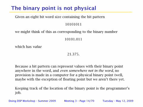
The binary point is not physical
Given an eight bit word size containing the bit pattern
10101011
we might think of this as corresponding to the binary number
10101.011
which has value
21.375.
Because a bit pattern can represent values with their binary point
anywhere in the word, and even somewhere not in the word, no
provision is made in a computer for a physical binary point (well,
maybe with the exception of floating point but we aren’t there yet.
Keeping track of the location of the binary point is the programmer’s
job.
Doing DSP Workshop – Summer 2009 Meeting 3 – Page 14/70 Tuesday – May 12, 2009

Q notation
Using a N-bit word for N = 8 consider b7b6b5b4b3b2b1b0
where
b7b6b5b4b3b2b1b0. — an integer value,
b7b6b5b4b3b2b1b0xxx.
b7b6b5b4.b3b2b1b0
b7.b6b5b4b3b2b1b0 — ranges from 0 to 2− 1/128.
A convention has developed to help in keeping track of the
location of the binary point. Assigned (mentally) to each value
is a number Qn where n is the index of the digit which the
radix point immediately follows.
Doing DSP Workshop – Summer 2009 Meeting 3 – Page 15/70 Tuesday – May 12, 2009
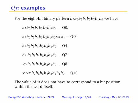
Qn examples
For the eight-bit binary pattern b7b6b5b4b3b2b1b0 we have
b7b6b5b4b3b2b1b0. — Q0,
b7b6b5b4b3b2b1b0xxx. — Q-3,
b7b6b5b4.b3b2b1b0 — Q4
b7.b6b5b4b3b2b1b0 — Q7
.b7b6b5b4b3b2b1b0 — Q8
x.xxb7b6b5b4b3b2b1b0 — Q10
The value of n does not have to correspond to a bit position
within the word itself.
Doing DSP Workshop – Summer 2009 Meeting 3 – Page 16/70 Tuesday – May 12, 2009
Computers (generally) use fixed word sizes
Most modern computers use binary (radix 2) and organize data
using fixed word sizes.
A computer might have a number of fixed word sizes. Typical
values are 8, 16, 32 and 64 bits per word.
Working in an FPGA it is generally convenient, but not
necessary, to use binary and common word sizes.
Computing is most often done using binary numbers. However,
other number systems exist and sometimes offer computational
efficiencies.
Because modern computers have word sizes which are a
multiple of four bits it is often convenient to express the
contents of a word using hexadecimal notation, radix 16.
Doing DSP Workshop – Summer 2009 Meeting 3 – Page 17/70 Tuesday – May 12, 2009
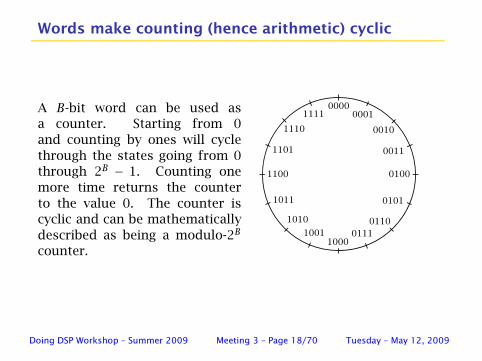
Words make counting (hence arithmetic) cyclic
A B-bit word can be used as
a counter. Starting from 0
and counting by ones will cycle
through the states going from 0
through 2B − 1. Counting one
more time returns the counter
to the value 0. The counter is
cyclic and can be mathematically
described as being a modulo-2B
counter.
00000001
0010
0011
0100
1111
0101
0110
10001001 0111
1010
1011
1101
1110
1100
Doing DSP Workshop – Summer 2009 Meeting 3 – Page 18/70 Tuesday – May 12, 2009
Range and resolution
For a given word size there is a minimum and maximum value
that can be represented. For unsigned binary, the range of
values that can be represented goes from 0 to 2N − 1.
The smallest step size between values is termed the resolution.
For unsigned binary integers the resolution is 1.
Doing DSP Workshop – Summer 2009 Meeting 3 – Page 19/70 Tuesday – May 12, 2009
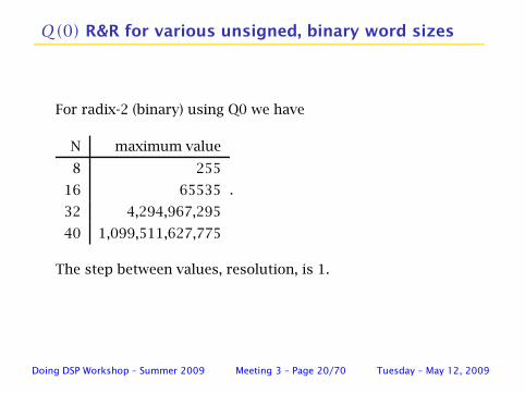
Q(0) R&R for various unsigned, binary word sizes
For radix-2 (binary) using Q0 we have
N maximum value
8 255
16 65535
32 4,294,967,295
40 1,099,511,627,775
.
The step between values, resolution, is 1.
Doing DSP Workshop – Summer 2009 Meeting 3 – Page 20/70 Tuesday – May 12, 2009

Q(N −1) R&R for various unsigned, binary word sizes
Q(N − 1) maximum value step size
Q7 2-1/128 0.0078125
Q15 2-1/32768 0.0000305175781
Q31 2-1/2147483648 4.65661287307739× 10⁻¹⁰
The step between values, resolution, is 2−(N−1).
For the general case, Q(n), it is 2−n.
Doing DSP Workshop – Summer 2009 Meeting 3 – Page 21/70 Tuesday – May 12, 2009
Negative values
Negative numbers first appear in history around 210 AD. By the
mid 18th century they had made their way to Europe where they
were considered nonsensical. Opinion has changed.
We are used to representing a negative decimal value simply
preceding it’s representation by a dash, −, called minus sign.
For example the negative of 12410 is written as −12410.
This representation has the name: signed magnitude.
It seems reasonable that when two numbers are added to each
other with the result equalling 0 one number must be the
negative of the other. Agreed?
Doing DSP Workshop – Summer 2009 Meeting 3 – Page 22/70 Tuesday – May 12, 2009
Survival of the fittest
One could simply reserve the left most bit in a word as the sign
bit. (Signed magnitude.)
Sounds simple and easy to do. Some early computers used this
representation. Signed magnitude might have advantages in
some FPGA designs even today.
Many ways of representing positive and negative numbers have
been tried.
The form that has survived (is most commonly used) is called
the two’s complement representation.
However, there are niches where other methods find use. We
consider one of these, called signed digit, for use with
multiplier-less MSP430 variants.
Doing DSP Workshop – Summer 2009 Meeting 3 – Page 23/70 Tuesday – May 12, 2009
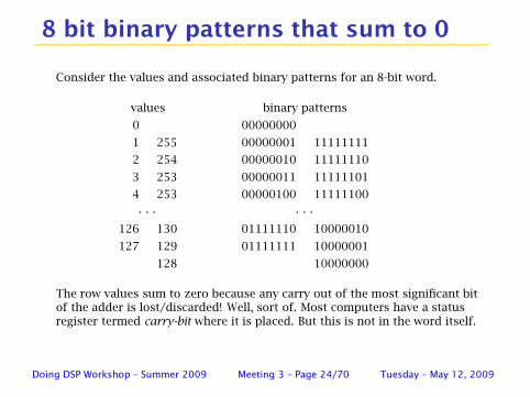
8 bit binary patterns that sum to 0
Consider the values and associated binary patterns for an 8-bit word.
values binary patterns
0 00000000
1 255 00000001 11111111
2 254 00000010 11111110
3 253 00000011 11111101
4 253 00000100 11111100
· · · · · ·
126 130 01111110 10000010
127 129 01111111 10000001
128 10000000
The row values sum to zero because any carry out of the most significant bitof the adder is lost/discarded! Well, sort of. Most computers have a statusregister termed carry-bit where it is placed. But this is not in the word itself.
Doing DSP Workshop – Summer 2009 Meeting 3 – Page 24/70 Tuesday – May 12, 2009
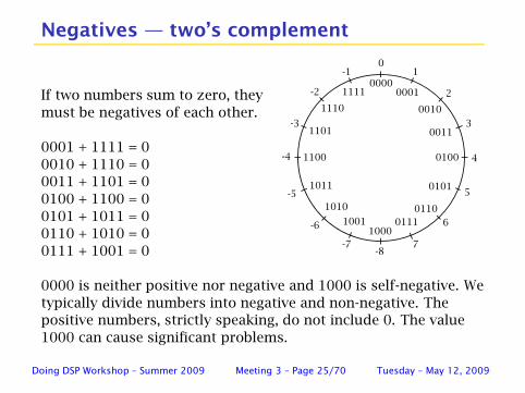
Negatives — two’s complement
If two numbers sum to zero, they
must be negatives of each other.
0001 + 1111 = 0
0010 + 1110 = 0
0011 + 1101 = 0
0100 + 1100 = 0
0101 + 1011 = 0
0110 + 1010 = 0
0111 + 1001 = 0
0000
0001
0010
0011
0100
1111
0101
0110
1000
1001 0111
1010
1011
1101
1110
1100
01
2
3
4
5
6
7
-1
-2
-3
-4
-5
-6
-7-8
0000 is neither positive nor negative and 1000 is self-negative. We
typically divide numbers into negative and non-negative. The
positive numbers, strictly speaking, do not include 0. The value
1000 can cause significant problems.
Doing DSP Workshop – Summer 2009 Meeting 3 – Page 25/70 Tuesday – May 12, 2009
To be done on the white board
◮ Converting 0010 into an 8-bit value.
◮ Converting 1110 into an 8-bit value.
◮ Converting 1000 into an 8-bit value.
◮ Shifting vs multiplying/dividing.
◮ Oops problem with right shifting negative values.
Doing DSP Workshop – Summer 2009 Meeting 3 – Page 26/70 Tuesday – May 12, 2009
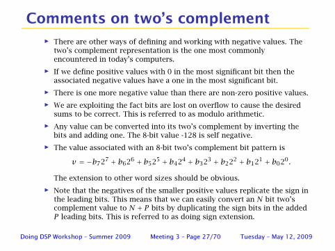
Comments on two’s complement
◮ There are other ways of defining and working with negative values. Thetwo’s complement representation is the one most commonlyencountered in today’s computers.
◮ If we define positive values with 0 in the most significant bit then theassociated negative values have a one in the most significant bit.
◮ There is one more negative value than there are non-zero positive values.
◮ We are exploiting the fact bits are lost on overflow to cause the desiredsums to be correct. This is referred to as modulo arithmetic.
◮ Any value can be converted into its two’s complement by inverting thebits and adding one. The 8-bit value -128 is self negative.
◮ The value associated with an 8-bit two’s complement bit pattern is
v = −b727 + b626 + b525 + b424 + b323 + b222 + b121 + b020.
The extension to other word sizes should be obvious.
◮ Note that the negatives of the smaller positive values replicate the sign inthe leading bits. This means that we can easily convert an N bit two’scomplement value to N + P bits by duplicating the sign bits in the addedP leading bits. This is referred to as doing sign extension.
Doing DSP Workshop – Summer 2009 Meeting 3 – Page 27/70 Tuesday – May 12, 2009
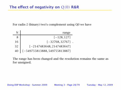
The effect of negativity on Q(0) R&R
For radix-2 (binary) two’s complement using Q0 we have
N range
8 [−128,127]
16 [−32768,32767]
32 [−2147483648,2147483647]
40 [−549755813888,549755813887]
.
The range has been changed and the resolution remains the same as
for unsigned.
Doing DSP Workshop – Summer 2009 Meeting 3 – Page 28/70 Tuesday – May 12, 2009
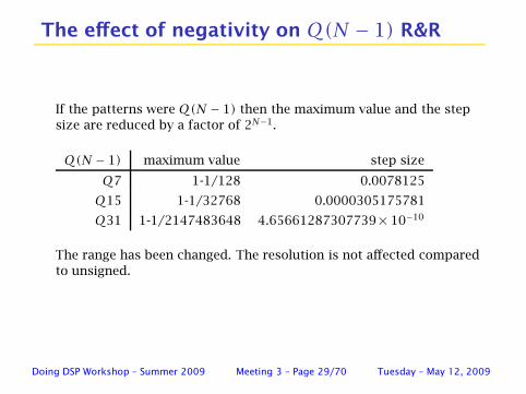
The effect of negativity on Q(N − 1) R&R
If the patterns were Q(N − 1) then the maximum value and the step
size are reduced by a factor of 2N−1.
Q(N − 1) maximum value step size
Q7 1-1/128 0.0078125
Q15 1-1/32768 0.0000305175781
Q31 1-1/2147483648 4.65661287307739× 10⁻¹⁰
The range has been changed. The resolution is not affected compared
to unsigned.
Doing DSP Workshop – Summer 2009 Meeting 3 – Page 29/70 Tuesday – May 12, 2009
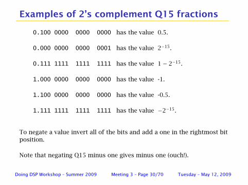
Examples of 2’s complement Q15 fractions
0.100 0000 0000 0000 has the value 0.5.
0.000 0000 0000 0001 has the value 2−15.
0.111 1111 1111 1111 has the value 1− 2−15.
1.000 0000 0000 0000 has the value -1.
1.100 0000 0000 0000 has the value -0.5.
1.111 1111 1111 1111 has the value −2−15.
To negate a value invert all of the bits and add a one in the rightmost bit
position.
Note that negating Q15 minus one gives minus one (ouch!).
Doing DSP Workshop – Summer 2009 Meeting 3 – Page 30/70 Tuesday – May 12, 2009
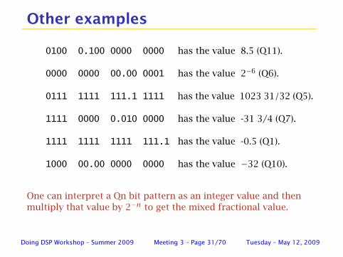
Other examples
0100 0.100 0000 0000 has the value 8.5 (Q11).
0000 0000 00.00 0001 has the value 2−6 (Q6).
0111 1111 111.1 1111 has the value 1023 31/32 (Q5).
1111 0000 0.010 0000 has the value -31 3/4 (Q7).
1111 1111 1111 111.1 has the value -0.5 (Q1).
1000 00.00 0000 0000 has the value −32 (Q10).
One can interpret a Qn bit pattern as an integer value and then
multiply that value by 2−n to get the mixed fractional value.
Doing DSP Workshop – Summer 2009 Meeting 3 – Page 31/70 Tuesday – May 12, 2009
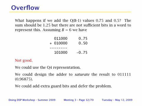
Overflow
What happens if we add the Q(B-1) values 0.75 and 0.5? The
sum should be 1.25 but there are not sufficient bits in a word to
represent this. Assuming B = 6 we have
011000 0.75
+ 010000 0.50
--------
101000 -0.75
Not good.
We could use the Q4 representation.
We could design the adder to saturate the result to 011111
(0.96875).
We could add extra guard bits and defer the problem.
Doing DSP Workshop – Summer 2009 Meeting 3 – Page 32/70 Tuesday – May 12, 2009
When can an overflow occur?
Overflow occurs when adding two negative numbers and getting
a positive result.
sign(#1) = 1, sign(#2) = 1, sign(sum) = 0.
Overflow occurs when adding two positive numbers and getting
a negative result.
sign(#1) = 0, sign(#2) = 0, sign(sum) = 1.
Overflow cannot occur when adding a negative number and a
positive number.
We normally plan to not have overflows. If one occurs we sort of
should maybe do something about it, yes?
Doing DSP Workshop – Summer 2009 Meeting 3 – Page 33/70 Tuesday – May 12, 2009
Allow overflow or saturate?
0 20 40 60 80 100
−2
0
2
x 104
sample index
sam
ple
valu
eSine wave samples fit into word size
0 20 40 60 80 100
−2
0
2
x 104
sample index
sam
ple
valu
e
Sine wave samples overflow word size
0 20 40 60 80 100
−2
0
2
x 104
sample index
sam
ple
valu
e
Sine wave samples saturated to word size
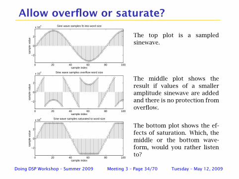
The top plot is a sampled
sinewave.
The middle plot shows the
result if values of a smaller
amplitude sinewave are added
and there is no protection from
overflow.
The bottom plot shows the ef-
fects of saturation. Which, the
middle or the bottom wave-
form, would you rather listen
to?
Doing DSP Workshop – Summer 2009 Meeting 3 – Page 34/70 Tuesday – May 12, 2009
Two’s complement overflow property
Given a set of numbers that sum to a value representable using
a given word size it does not matter how many times an
overflow occurs in forming the sum. The result will be correct.
This assumes that one does not saturate automatically when an
overflow occurs.
This property is a consequence of the cyclic nature of the two’s
complement representation. One can think of the overflow
process as having gone around the number circle as many times
in the clockwise direction as in the counter-clockwise direction.
Depending on the hardware resources present it is generally not
wise to saturate early in a series of calculations.
However, when a calculation is done, one really needs to know
whether the final result has overflowed or not.
Doing DSP Workshop – Summer 2009 Meeting 3 – Page 35/70 Tuesday – May 12, 2009
Detecting and handling an overflow
Not so easy working in C. Design so that it can’t happen?
Requires lots of thought and effort.
Use C intrinsics. Not necessarily easy either.
Work at the machine level using assembly language. For mission
critical work, what else can one do?
This will be revisited when we start actually calculating.
Doing DSP Workshop – Summer 2009 Meeting 3 – Page 36/70 Tuesday – May 12, 2009
Recap
◮ Normally use binary values organized into words.
◮ Fixed word size causes cyclic counting.
◮ Bit order : bN−1bN−2 . . . b2b1b0.
◮ Binary value: v =
N−1∑
n=0
bn2n.
◮ Signed values typically use two’s complement form.
◮ To form two’s complement: invert bits and add 1.
◮ Two’s complement value: −bN−12N−1 +
N−2∑
n=0
bn2n.
◮ Binary and two’s complement addition use same hardware.
Doing DSP Workshop – Summer 2009 Meeting 3 – Page 37/70 Tuesday – May 12, 2009
More recap
◮ When adding values, sum might not fit (overflow).
◮ Solutions: do nothing, add bits, saturate.
◮ Two’s complement is robust to intermediate overflows!
◮ Generally saturate only when storing sum!!!
◮ Binary point separates integer and fraction parts.
◮ Binary point does not have physical presence.
◮ Qn notation helps keep track of BP location.
◮ Need to align Qn and Qm values prior to adding.
Doing DSP Workshop – Summer 2009 Meeting 3 – Page 38/70 Tuesday – May 12, 2009
Using the range [−1,1) is often convenient
Consider implementing an FIR filter
y[n] =
P∑
k=0
b[k]x[n− k] .
Assume the input samples are scaled such that −1 <= x[n] < 1.
Frequently scaling an FIR filter to have maximum gain of 1 results in
coefficient values having magnitude less than 1.
Each of the individual products lie in the range [−1,1). Because the
filter is assumed to be designed for a maximum gain of 1 then (for
most waveforms) the filter outputs lie in the range of [−1,1).
This argues that it is useful to represent sample values and coefficient
values as Q(N-1).
Doing DSP Workshop – Summer 2009 Meeting 3 – Page 39/70 Tuesday – May 12, 2009
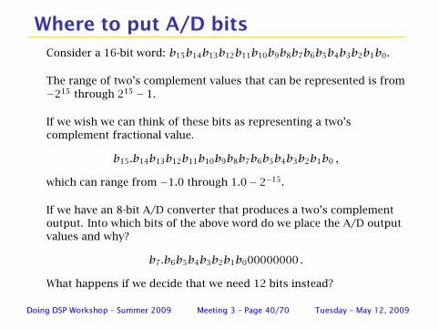
Where to put A/D bits
Consider a 16-bit word: b15b14b13b12b11b10b9b8b7b6b5b4b3b2b1b0.
The range of two’s complement values that can be represented is from
−215 through 215 − 1.
If we wish we can think of these bits as representing a two’s
complement fractional value.
b15.b14b13b12b11b10b9b8b7b6b5b4b3b2b1b0 ,
which can range from −1.0 through 1.0− 2−15.
If we have an 8-bit A/D converter that produces a two’s complement
output. Into which bits of the above word do we place the A/D output
values and why?
b7.b6b5b4b3b2b1b000000000 .
What happens if we decide that we need 12 bits instead?
Doing DSP Workshop – Summer 2009 Meeting 3 – Page 40/70 Tuesday – May 12, 2009
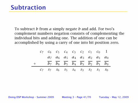
Subtraction
To subtract b from a simply negate b and add. For two’s
complement numbers negation consists of complementing the
individual bits and adding one. The addition of one can be
accomplished by using a carry of one into bit position zero.
c7 c6 c5 c4 c3 c2 c1 c0 1
a7 a6 a5 a4 a3 a2 a1 a0
+ b7 b6 b5 b4 b3 b2 b1 b0
c7 s7 s6 s5 s4 s3 s2 s1 s0
Doing DSP Workshop – Summer 2009 Meeting 3 – Page 41/70 Tuesday – May 12, 2009
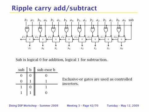
Ripple carry add/subtract
s0s1s2s3s4s5s6s7
b7 b6a7 a6
c0c7 c6
+ + +c1c2c3c4c5
++ +++
b5 b4 b3 b2 b1 b0a4a5 a3 a2 a1 a0 sub
Sub is logical 0 for addition, logical 1 for subtraction.
sub b sub exor b
0 0 0
0 1 1
1 0 1
1 1 0
Exclusive-or gates are used as controlled
inverters.
Doing DSP Workshop – Summer 2009 Meeting 3 – Page 42/70 Tuesday – May 12, 2009
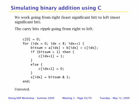
Simulating binary addition using C
We work going from right (least significant bit) to left (most
significant bit).
The carry bits ripple going from right to left.
c[0] = 0;
for (idx = 0; idx < 8; idx++) {
bitsum = a[idx] + b[idx] + c[idx];
if (bitsum > 1) then {
c[idx+1] = 1;
}
else {
c[idx+1] = 0;
}
s[idx] = bitsum & 1;
end;
Untested.
Doing DSP Workshop – Summer 2009 Meeting 3 – Page 43/70 Tuesday – May 12, 2009
Bit-serial arithmetic
◮ Used a lot years ago when logic was dearly expensive, bulky
and power hungry.
◮ Often used in hand held calculators.
◮ Generally requires less FPGA fabric area than parallel.
◮ Generally slower than parallel, but not necessarily.
◮ I designed and implemented a PN sequence correlator that
adds 63 16-bit numbers in 25 clock cycles.
◮ Generally trades higher execution time for smaller FPGA
footprint.
◮ Interesting and challenging to use.
Doing DSP Workshop – Summer 2009 Meeting 3 – Page 44/70 Tuesday – May 12, 2009
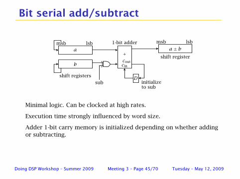
Bit serial add/subtract
a
msb
sub
b
lsba± b
D
+shift register
shift registers
msb lsb
cin
cout
1-bit adder
initializeto sub
Minimal logic. Can be clocked at high rates.
Execution time strongly influenced by word size.
Adder 1-bit carry memory is initialized depending on whether adding
or subtracting.
Doing DSP Workshop – Summer 2009 Meeting 3 – Page 45/70 Tuesday – May 12, 2009
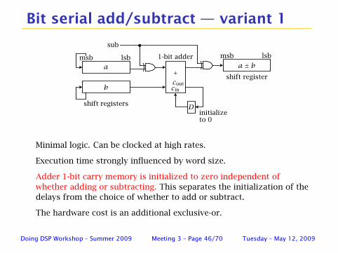
Bit serial add/subtract — variant 1
a
msb
sub
b
lsba± b
D
+shift register
shift registers
msb lsb
cin
cout
1-bit adder
initializeto 0
Minimal logic. Can be clocked at high rates.
Execution time strongly influenced by word size.
Adder 1-bit carry memory is initialized to zero independent of
whether adding or subtracting. This separates the initialization of the
delays from the choice of whether to add or subtract.
The hardware cost is an additional exclusive-or.
Doing DSP Workshop – Summer 2009 Meeting 3 – Page 46/70 Tuesday – May 12, 2009
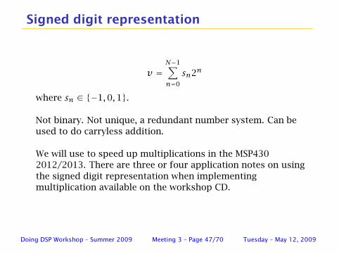
Signed digit representation
v =
N−1∑
n=0
sn2n
where sn ∈ {−1,0,1}.
Not binary. Not unique, a redundant number system. Can be
used to do carryless addition.
We will use to speed up multiplications in the MSP430
2012/2013. There are three or four application notes on using
the signed digit representation when implementing
multiplication available on the workshop CD.
Doing DSP Workshop – Summer 2009 Meeting 3 – Page 47/70 Tuesday – May 12, 2009
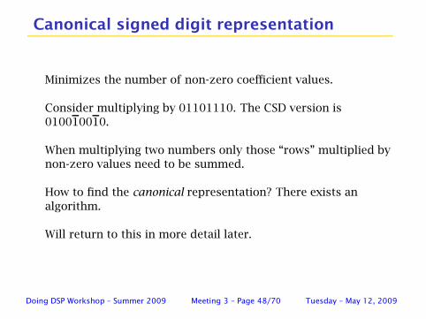
Canonical signed digit representation
Minimizes the number of non-zero coefficient values.
Consider multiplying by 01101110. The CSD version is
010010010.
When multiplying two numbers only those “rows” multiplied by
non-zero values need to be summed.
How to find the canonical representation? There exists an
algorithm.
Will return to this in more detail later.
Doing DSP Workshop – Summer 2009 Meeting 3 – Page 48/70 Tuesday – May 12, 2009
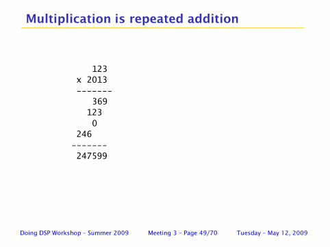
Multiplication is repeated addition
123
x 2013
-------
369
123
0
246
-------
247599
Doing DSP Workshop – Summer 2009 Meeting 3 – Page 49/70 Tuesday – May 12, 2009
Multiplication terminology
multiplicand×multiplier = product
multiplicand is what is being multiplied
multiplier what is doing the multiplication
product is the result
Consider looking at Behrooz Parhami’s multiplication lecture
slides: Parhami
Doing DSP Workshop – Summer 2009 Meeting 3 – Page 50/70 Tuesday – May 12, 2009
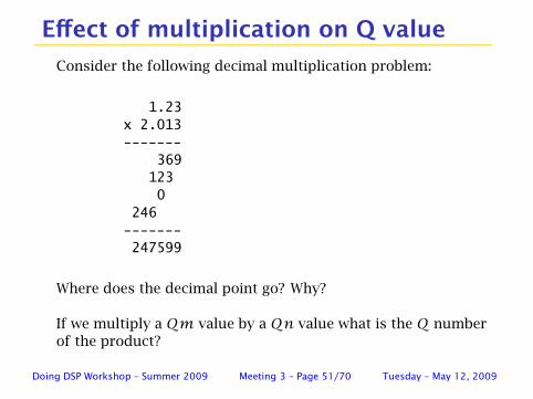
Effect of multiplication on Q value
Consider the following decimal multiplication problem:
1.23
x 2.013
-------
369
123
0
246
-------
247599
Where does the decimal point go? Why?
If we multiply a Qm value by a Qn value what is the Q number
of the product?
Doing DSP Workshop – Summer 2009 Meeting 3 – Page 51/70 Tuesday – May 12, 2009
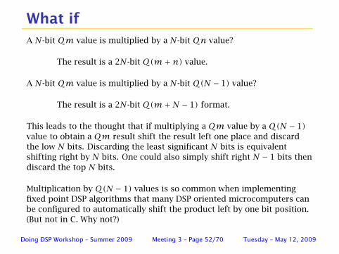
What if
A N-bit Qm value is multiplied by a N-bit Qn value?
The result is a 2N-bit Q(m+n) value.
A N-bit Qm value is multiplied by a N-bit Q(N − 1) value?
The result is a 2N-bit Q(m+N − 1) format.
This leads to the thought that if multiplying a Qm value by a Q(N − 1)
value to obtain a Qm result shift the result left one place and discard
the low N bits. Discarding the least significant N bits is equivalent
shifting right by N bits. One could also simply shift right N − 1 bits then
discard the top N bits.
Multiplication by Q(N − 1) values is so common when implementing
fixed point DSP algorithms that many DSP oriented microcomputers can
be configured to automatically shift the product left by one bit position.
(But not in C. Why not?)
Doing DSP Workshop – Summer 2009 Meeting 3 – Page 52/70 Tuesday – May 12, 2009
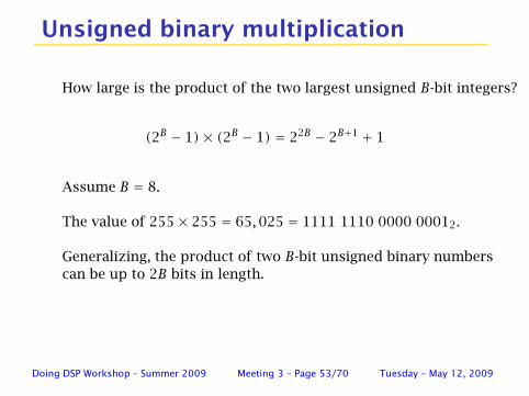
Unsigned binary multiplication
How large is the product of the two largest unsigned B-bit integers?
(2B − 1)× (2B − 1) = 22B − 2B+1 + 1
Assume B = 8.
The value of 255× 255 = 65,025 = 1111 1110 0000 00012.
Generalizing, the product of two B-bit unsigned binary numbers
can be up to 2B bits in length.
Doing DSP Workshop – Summer 2009 Meeting 3 – Page 53/70 Tuesday – May 12, 2009

Two’s complement multiplication
Four cases:
Positive multiplier times positive.
Positive multiplier times negative.
Negative multiplier time positive.
Negative multiplier times negative.
Brute force would be to negate any negative values, multiply us-
ing unsigned multiplication hardware and, if necessary, negate the
result. Sometimes brute force is a reasonable way to go!
Doing DSP Workshop – Summer 2009 Meeting 3 – Page 54/70 Tuesday – May 12, 2009
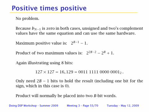
Positive times positive
No problem.
Because bN−1 is zero in both cases, unsigned and two’s complement
values have the same equation and can use the same hardware.
Maximum positive value is: 2B−1 − 1.
Product of two maximum values is: 22B−2 − 2B + 1.
Again illustrating using 8 bits:
127× 127 = 16,129 = 0011 1111 0000 00012 .
Only need 2B − 1 bits to hold the result (including one bit for the
sign, which in this case is 0).
Product will normally be placed into two B-bit words.
Doing DSP Workshop – Summer 2009 Meeting 3 – Page 55/70 Tuesday – May 12, 2009
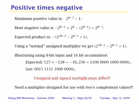
Positive times negative
Maximum positive value is: 2B−1 − 1.
Most negative value is −2B−1 = 2B − (2B−1) = 2B−1.
Expected product is: −(22B−2 − 2B−1 + 1).
Using a “normal” unsigned multiplier we get (22B−2 − 2B−1 + 1).
Illustrating using 8-bit input and 16 bit accumulator:
Expected: 127×−128 = −16,256 = 1100 0000 1000 00002.
Got: 0011 1111 1000 00002.
Unsigned and signed multiplication differ!!!
Need a multiplier designed for use with two’s complement values!!!
Doing DSP Workshop – Summer 2009 Meeting 3 – Page 56/70 Tuesday – May 12, 2009
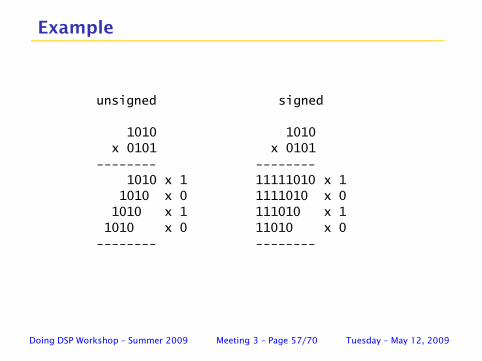
Example
unsigned signed
1010 1010
x 0101 x 0101
-------- --------
1010 x 1 11111010 x 1
1010 x 0 1111010 x 0
1010 x 1 111010 x 1
1010 x 0 11010 x 0
-------- --------
Doing DSP Workshop – Summer 2009 Meeting 3 – Page 57/70 Tuesday – May 12, 2009
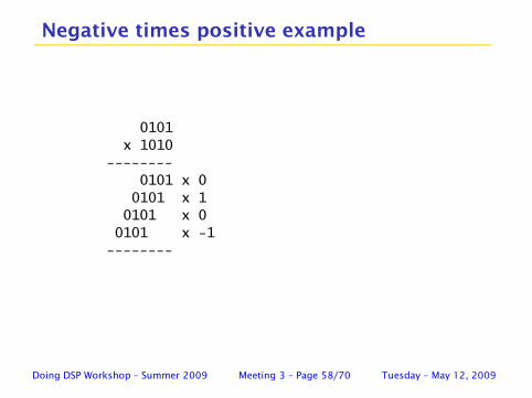
Negative times positive example
0101
x 1010
--------
0101 x 0
0101 x 1
0101 x 0
0101 x -1
--------
Doing DSP Workshop – Summer 2009 Meeting 3 – Page 58/70 Tuesday – May 12, 2009
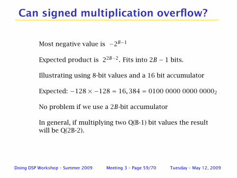
Can signed multiplication overflow?
Most negative value is −2B−1
Expected product is 22B−2. Fits into 2B − 1 bits.
Illustrating using 8-bit values and a 16 bit accumulator
Expected: −128×−128 = 16,384 = 0100 0000 0000 00002
No problem if we use a 2B-bit accumulator
In general, if multiplying two Q(B-1) bit values the result
will be Q(2B-2).
Doing DSP Workshop – Summer 2009 Meeting 3 – Page 59/70 Tuesday – May 12, 2009
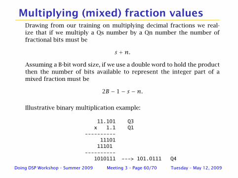
Multiplying (mixed) fraction valuesDrawing from our training on multiplying decimal fractions we real-
ize that if we multiply a Qs number by a Qn number the number of
fractional bits must be
s +n.
Assuming a B-bit word size, if we use a double word to hold the product
then the number of bits available to represent the integer part of a
mixed fraction must be
2B − 1− s −n.
Illustrative binary multiplication example:
11.101 Q3x 1.1 Q1
----------11101
11101----------
1010111 ---> 101.0111 Q4
Doing DSP Workshop – Summer 2009 Meeting 3 – Page 60/70 Tuesday – May 12, 2009
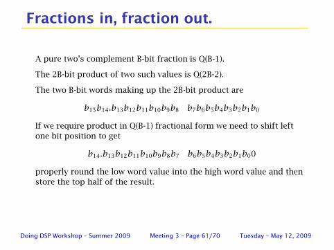
Fractions in, fraction out.
A pure two’s complement B-bit fraction is Q(B-1).
The 2B-bit product of two such values is Q(2B-2).
The two B-bit words making up the 2B-bit product are
b15b14.b13b12b11b10b9b8 b7b6b5b4b3b2b1b0
If we require product in Q(B-1) fractional form we need to shift left
one bit position to get
b14.b13b12b11b10b9b8b7 b6b5b4b3b2b1b00
properly round the low word value into the high word value and then
store the top half of the result.
Doing DSP Workshop – Summer 2009 Meeting 3 – Page 61/70 Tuesday – May 12, 2009
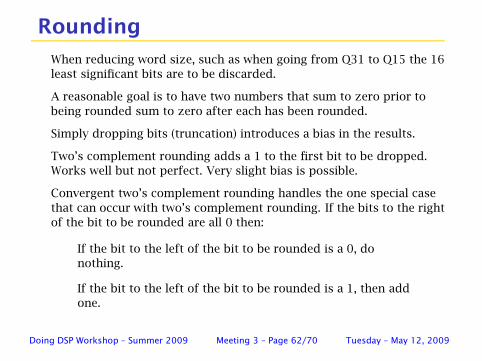
Rounding
When reducing word size, such as when going from Q31 to Q15 the 16
least significant bits are to be discarded.
A reasonable goal is to have two numbers that sum to zero prior to
being rounded sum to zero after each has been rounded.
Simply dropping bits (truncation) introduces a bias in the results.
Two’s complement rounding adds a 1 to the first bit to be dropped.
Works well but not perfect. Very slight bias is possible.
Convergent two’s complement rounding handles the one special case
that can occur with two’s complement rounding. If the bits to the right
of the bit to be rounded are all 0 then:
If the bit to the left of the bit to be rounded is a 0, do
nothing.
If the bit to the left of the bit to be rounded is a 1, then add
one.
Doing DSP Workshop – Summer 2009 Meeting 3 – Page 62/70 Tuesday – May 12, 2009

Round then truncate example
This example uses a 8-bit word size. An 8-bit value is to be
converted to 4 bits keeping the 4 most significant bits.
Two’s complement rounding. First two 8-bit values sum to zero
before rounding then truncating but not necessarily afterwards.
x + y x + yvalue: 1100 1010 0011 0110 0011 1000 1100 1000rounded: 1101 0011 0100 1101
Convergent rounding. First two 8-bit values sum to zero before
and after rounding and bit size reduction. The second two
values sum to zero before and after rounding and bit size
reduction.
x + y x + yvalue: 1100 1010 0011 0110 0011 1000 1100 1000rounded: 1101 0011 0100 1100
Doing DSP Workshop – Summer 2009 Meeting 3 – Page 63/70 Tuesday – May 12, 2009
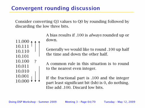
Convergent rounding discussion
Consider converting Q3 values to Q0 by rounding followed by
discarding the low three bits.
10.00010.00110.01010.01110.10010.10110.11010.11111.000
?
A bias results if .100 is always rounded up or
down.
Generally we would like to round .100 up half
the time and down the other half.
A common rule in this situation is to round
to the nearest even integer.
If the fractional part is .100 and the integer
part least significant bit (lsb) is 0, do nothing.
Else add .100. Discard low bits.
Doing DSP Workshop – Summer 2009 Meeting 3 – Page 64/70 Tuesday – May 12, 2009
Hand wave guess at the bias
◮ Let n be the number of low bits being discarded.
◮ There are 2N − 1 values that will be changed.
◮ The mid value should be rounded positive half of the time.
If not, there should (might?) be a bias of +1/2n+1.
◮ Is this amount of bias important to the task at hand? If not,
two’s complement rounding requires less hardware.
◮ Do you believe me? (Do I?) Something to look at more
carefully when time permits.
Doing DSP Workshop – Summer 2009 Meeting 3 – Page 65/70 Tuesday – May 12, 2009
The two primary fixed point concerns
Other than getting the algorithm correct the two key concerns
when using fixed point are felt to be:
◮ Guarding against over flow. Don’t forget that rounding can
also call over flow.
◮ Minimizing round off errors when values have their word
sizes reduced.
There is no real challenge in programming a FIR filter on a PC
using 64-bit floating point arithmetic. However, it is very difficult
to build a PC into a hearing aid.
Doing DSP Workshop – Summer 2009 Meeting 3 – Page 66/70 Tuesday – May 12, 2009
Comments on saturation
Having, and using, guard bits help against overflow. What
should be done once overflow has happened?
It depends.
A filter design might be exploiting the two’s complement
overflow resiliency.
For example: consider a FIR filter having an equal number of
positive and negative coefficient values. The filter may not be
susceptible to overflow if the terms are ordered in
positive/negative pairs. However if all of the positive terms and
all the negative terms are summed separately there might be an
overflow prior to adding the two sub sums together. Saturating
at the time of overflow would be the wrong thing to do in this
case.
Doing DSP Workshop – Summer 2009 Meeting 3 – Page 67/70 Tuesday – May 12, 2009
More saturation comments
In the C5510 the guard bits extent the range a sum can “overlow” into
without loss of most significant bits from ±1 to ±128 (nominal).
This should be quite sufficient for most worst case design situations.
(It’s the designer’s responsibility to make sure this is so.)
Saturating upon moving a result from an accumulator into memory or
another register is generally the safest strategy. If the value is too
large to fit into a regular word it should be either scaled or saturated.
The SATD bit in status register 1 allows the saturating values
whenever an overflow occurs. This is affected by the M40 bit.
The TI instruction set supports the saturate( ) operand modifier
which can be used to explicitly saturate when desired.
Doing DSP Workshop – Summer 2009 Meeting 3 – Page 68/70 Tuesday – May 12, 2009
What about division?
Historically this has been considered a difficult problem.
"He who can properly define and divide is to be considered a god."
Plato (ca 429-347 BC)
Doing DSP Workshop – Summer 2009 Meeting 3 – Page 69/70 Tuesday – May 12, 2009
Floating point
Do you know what floating point is and how it works?
The Piccolo C/C++ compiler supports floating point
calculations.
The Piccolo does not possess floating point hardware. All
floating point calculations are simulated . . . done in software.
There are variants in the C2000 family that include floating
point hardware.
Doing DSP Workshop – Summer 2009 Meeting 3 – Page 70/70 Tuesday – May 12, 2009