megajoist - lightweight steel framing · megajoist - lightweight steel framing ... megajoist design...
TRANSCRIPT

MegaJoist - Lightweight Steel Framing
January 2014
Load Tables for Floor
Joist Application
A
P
C
t
B H

1
Commentary
Introduction...................................................................................................................................2
Product Identification....................................................................................................................2
Section Geometries......................................................................................................................2
MegaJoist Section Property Tables ..............................................................................................3
Track Section Property Tables......................................................................................................4
MegaJoist Load Tables.................................................................................................................4
Symbols........................................................................................................................................5
MegaJoist Design Example..........................................................................................................6
Roger A. LaBoube, Ph.D, P.E.......................................................................................................7
MegaJoist Section Properties ...................................................................................................8
Track Section Properties ..........................................................................................................10
MegaJoist Load Tables .............................................................................................................12
Table of Contents

2
1. Introduction
The technical data contained herein is intended as
an aid to the design professional and should not be
used to replace the judgment of a qualified Engineer
or Architect.
2. Product Identification
The cold-formed steel framing manufacturers use a
universal designator system for their products. The
designator is a four part code which identifies depth,
flange width, member type and material thickness.
Commentary
1000 M 162 - 54
Member depth in
1/100ths inches.
Thus 1000 means
1000/100=10”
Flange width in
1/100ths inches.
Thus 162 means
162/100=1.62”
or 1 5/8”
Style:
S = MegaJoist sections
T = Track sections
U = Channel sections
F = Furring channel sections
Minimum thickness in
1/1000ths inches.
Thus 54means
54/1000=0.054”
Example: 1000M162-54
3. Section Geometries
3.1 Section geometries are identified by the product designation as defined in the previous section.
3.2 MegaJoist dimensions are as follows:
3
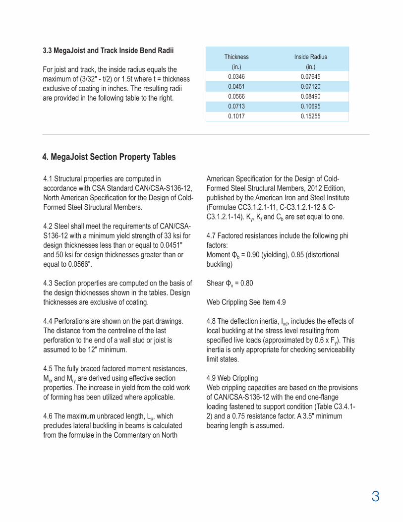
3.3 MegaJoist and Track Inside Bend Radii
For joist and track, the inside radius equals the
maximum of (3/32" - t/2) or 1.5t where t = thickness
exclusive of coating in inches. The resulting radii
are provided in the following table to the right.
4. MegaJoist Section Property Tables
4.1 Structural properties are computed in
accordance with CSA Standard CAN/CSA-S136-12,
North American Specification for the Design of Cold-
Formed Steel Structural Members.
4.2 Steel shall meet the requirements of CAN/CSA-
S136-12 with a minimum yield strength of 33 ksi for
design thicknesses less than or equal to 0.0451"
and 50 ksi for design thicknesses greater than or
equal to 0.0566".
4.3 Section properties are computed on the basis of
the design thicknesses shown in the tables. Design
thicknesses are exclusive of coating.
4.4 Perforations are shown on the part drawings.
The distance from the centreline of the last
perforation to the end of a wall stud or joist is
assumed to be 12" minimum.
4.5 The fully braced factored moment resistances,
Mrx and Mry are derived using effective section
properties. The increase in yield from the cold work
of forming has been utilized where applicable.
4.6 The maximum unbraced length, Lu, which
precludes lateral buckling in beams is calculated
from the formulae in the Commentary on North
American Specification for the Design of Cold-
Formed Steel Structural Members, 2012 Edition,
published by the American Iron and Steel Institute
(Formulae CC3.1.2.1-11, C-C3.1.2.1-12 & C-
C3.1.2.1-14). Ky, Kt and Cb are set equal to one.
4.7 Factored resistances include the following phi
factors:
Moment Φb = 0.90 (yielding), 0.85 (distortional
buckling)
Shear Φv = 0.80
Web Crippling See Item 4.9
4.8 The deflection inertia, Ixd, includes the effects of
local buckling at the stress level resulting from
specified live loads (approximated by 0.6 x Fy). This
inertia is only appropriate for checking serviceability
limit states.
4.9 Web Crippling
Web crippling capacities are based on the provisions
of CAN/CSA-S136-12 with the end one-flange
loading fastened to support condition (Table C3.4.1-
2) and a 0.75 resistance factor. A 3.5" minimum
bearing length is assumed.
Thickness Inside Radius
(in.) (in.)
0.0346 0.07645
0.0451 0.07120
0.0566 0.08490
0.0713 0.10695
0.1017 0.15255

4
4.10 Distortional Buckling
Distortional buckling properties and factored
resistance are based on an unperforated section.
Neither S136-12, Sections A – G, nor do these tables
include provisions for the weak axis distortional
buckling of joists (lips in compression). Where weak
axis distortional buckling is a design concern,
additional calculation is required.
5. Track Section Property Tables
5.1 The previous Commentary Items 4.1 - 4.3 apply.
5.2 The factored moment resistance, Mrx, is derived
using effective section properties with the cold work
of forming conservatively neglected. Factored shear
and moment resistances, Vr and Mrx, include a 0.8
and 0.9 resistance factor respectively.
5.3 The deflection inertia, Ixd, includes the effects of
local buckling at the stress level resulting from
specified live loads (approximated by 0.6 x Fy). This
inertia is only appropriate for checking serviceability
limit states.
6. Floor Joist Load Tables
6.1 The load tables are computed in accordance with
the requirements of the National Building Code of
Canada 2010 and CAN/CSA S136-12, North
American Specification for the Design of Cold-
Formed Steel Structural Members.
6.2 Joist material, geometry and properties conform
to the Joist Section Property Tables and
Commentary Item 4.
6.3 Strength loads are limited by end shear or mid-
span moment. Strength loads are to be checked
against the sum of the factored live and dead loads.
The live load factor is 1.5 and the dead load factor is
1.25. Deflection loads are to be checked against
specified (unfactored) design live loads.
For the joist tables the sheathing is not relied on to
reduce the effect of distortional buckling. The
factored moment resistance is the lesser of the fully
restrained moment for local buckling and the
resisting moment for distortional buckling with
kφ = 0.
6.4 No vibration limit state has been imposed.
6.5 Joists are analyzed as single span members with
adequate web stiffeners provided at the location of
reactions or concentrated loads. Spans are not
limited by web crippling. Design web stiffeners to
accommodate concentrated loads or reactions. Refer
to CAN/CSA S136-12.
6.6 Joists are assumed to be fully restrained with
respect to lateral instability and with respect to
torsionally eccentric loads not applied through the
shear centre. Loads are assumed to be uniformly
distributed.
6.7 Allowable specified loads for other deflection
limits can be calculated by multiplying the L/360
specified loads by the following factors:
6.8 Provide floor sheathing supplemented by
bridging as required by S136012 (S136-12
references the North American Standard for Cold-
Formed Steel Framing – Floor and Roof System
Design, AISI S210-12, where detailed requirements
are provided).
Required Factor
Deflection Limit
L/480 0.750
L/360 1.000
L/300 1.200
L/240 1.500
L/180 2.000
5
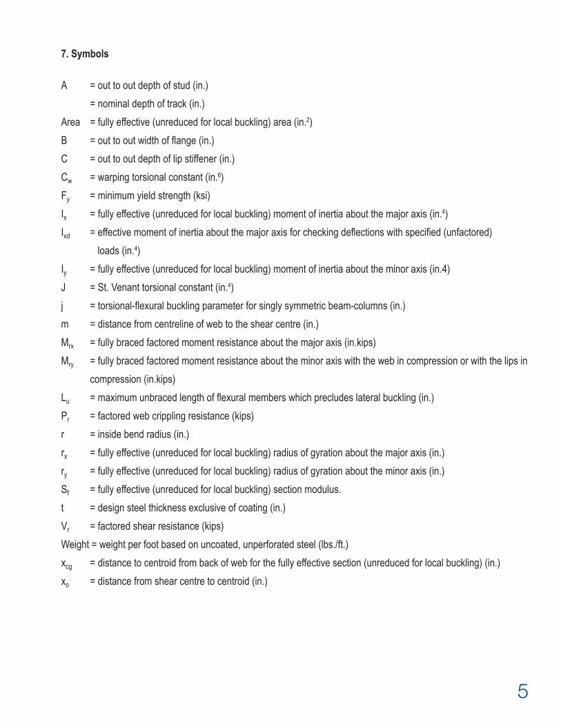
7. Symbols
A = out to out depth of stud (in.)
= nominal depth of track (in.)
Area = fully effective (unreduced for local buckling) area (in.2)
B = out to out width of flange (in.)
C = out to out depth of lip stiffener (in.)
Cw = warping torsional constant (in.6)
Fy = minimum yield strength (ksi)
Ix = fully effective (unreduced for local buckling) moment of inertia about the major axis (in.4)
Ixd = effective moment of inertia about the major axis for checking deflections with specified (unfactored)
loads (in.4)
Iy = fully effective (unreduced for local buckling) moment of inertia about the minor axis (in.4)
J = St. Venant torsional constant (in.4)
j = torsional-flexural buckling parameter for singly symmetric beam-columns (in.)
m = distance from centreline of web to the shear centre (in.)
Mrx = fully braced factored moment resistance about the major axis (in.kips)
Mry = fully braced factored moment resistance about the minor axis with the web in compression or with the lips in
compression (in.kips)
Lu = maximum unbraced length of flexural members which precludes lateral buckling (in.)
Pr = factored web crippling resistance (kips)
r = inside bend radius (in.)
rx = fully effective (unreduced for local buckling) radius of gyration about the major axis (in.)
ry = fully effective (unreduced for local buckling) radius of gyration about the minor axis (in.)
Sf = fully effective (unreduced for local buckling) section modulus.
t = design steel thickness exclusive of coating (in.)
Vr = factored shear resistance (kips)
Weight = weight per foot based on uncoated, unperforated steel (lbs./ft.)
xcg = distance to centroid from back of web for the fully effective section (unreduced for local buckling) (in.)
xo = distance from shear centre to centroid (in.)
6
8. Design Example
Given:
Specified (unfactored) live load = 40 psf
Specified (unfactored ) dead load = 15 psf
Required joist depth for architectural considerations =
8 in.
16'-0" single span
Calculations:
Factored load = aDD + aLL = (1.25)(15) + (1.50)(40)
= 78.8 psf
Try 800M162-54 (50 ksi) MegaJoist (with design t =
0.0566" and Fy = 50 ksi) spaced at 16" o.c.
Strength = 91 > 78.8 psf OK
L/360 = 45 > 40 psf OK
Conclusion:
Use 800M162-54 (50 ksi) joist (with design t =
0.0566" and Fy = 50 ksi) spaced at 16" o.c.
Provide web stiffeners over the supports designed in
accordance with the requirements of CAN/CSA-S136-
07. Provide top flange floor sheathing in combination
with bottom flange bridging to meet the requirements
of S136-07.
Where vibration is a concern, additional engineering
is required.

7
Roger A. LaBoube, Ph.D, P.E.
The load tables and technical information contained
in this catalogue were prepared by Dr. Roger A.
LaBoube, Ph.D, P.E. Professor LaBoube received
his engineering degrees from the University of
Missouri-Rolla. He has approximately 14 years of
industry experience, with ten of those years with
Butler Manufacturing Company in Research and
Development.
Since 1978, Dr. LaBoube has held faculty positions
at Iowa State University, the University of Kansas,
and the Missouri University of Science & Technology
(formerly University of Missouri-Rolla). Dr. Laboube
is Curator’s Teaching Professor Emeritus of Civil
Engineering and Director of the Center for Cold-
Formed Steel Structures at Missouri University of
Science & Technology.
Dr. Laboube is active professionally in the following
activities:
• A member of the AISI Committee on Specifications
for the Design of Cold-Formed Steel Structural
Members.
• Currently serves as Chairman of the Education
Subcommittee of the Committee on Specifications.
• A member of the AISI Committee on Framing
Standards and chairs the Design Methods
Subcommittee.
• Co-author with Dr. Wei-Wen Yu, Cold-Formed Steel
Design, 4th edition, John Wiley & Sons.
• Has authored or co-authored the following AISI
design guides:
The Design Guide for Cold-Formed Steel Trusses
Design Guide for Beams with Web Openings
A Design Guide for Designing with Standing Seam
Roof Panels (co-author)
• Is actively involved in cold-formed steel research.
• Has served as a consultant to manufacturers and
consulting engineers on numerous topics related to
cold-formed steel members and connections.
Professor LaBoube can be contacted at:
Tel: (573)341-4481
Fax: (573)341-4729

8
Thickness Depth Flange Lip Weight Yield Area xcg m xo Cw J
t A B C Fy
(in.) (in.) (in.) (in.) (lbs/ft) (ksi) (in.2) (in.) (in.) (in.) (in.6) (in.4)
800M162-43 0.0451 8.000 1.625 0.500 1.828 33 0.537 0.348 0.595 -0.921 1.994 0.000364
800M162-54 0.0566 8.000 1.625 0.500 2.278 50 0.670 0.348 0.587 -0.908 2.415 0.000715
800M162-68 0.0713 8.000 1.625 0.500 2.843 50 0.836 0.349 0.577 -0.890 2.897 0.001416
1000M162-43 0.0451 10.000 1.625 0.500 2.134 33 0.627 0.301 0.539 -0.818 3.299 0.000425
1000M162-54 0.0566 10.000 1.625 0.500 2.663 50 0.783 0.302 0.531 -0.805 4.000 0.000836
1000M162-68 0.0713 10.000 1.625 0.500 3.329 50 0.978 0.303 0.521 -0.788 4.806 0.001658
1200M162-54 0.0566 12.000 1.625 0.500 3.049 50 0.896 0.268 0.485 -0.724 6.045 0.000957
1200M162-68 0.0713 12.000 1.625 0.500 3.814 50 1.121 0.269 0.475 -0.708 7.270 0.001899
1400M162-54 0.0566 14.000 1.625 0.500 3.434 50 1.009 0.241 0.446 -0.659 8.566 0.001078
1400M162-68 0.0713 14.000 1.625 0.500 4.299 50 1.263 0.243 0.437 -0.644 10.309 0.002141
800M200-43 0.0451 8.000 2.000 0.625 1.981 33 0.582 0.489 0.807 -1.273 3.677 0.000395
800M200-54 0.0566 8.000 2.000 0.625 2.471 50 0.726 0.489 0.799 -1.259 4.480 0.000775
800M200-68 0.0713 8.000 2.000 0.625 3.086 50 0.907 0.488 0.788 -1.241 5.422 0.001537
1000M200-43 0.0451 10.000 2.000 0.625 2.288 33 0.672 0.426 0.738 -1.142 6.043 0.000456
1000M200-54 0.0566 10.000 2.000 0.625 2.856 50 0.839 0.427 0.731 -1.129 7.373 0.000896
1000M200-68 0.0713 10.000 2.000 0.625 3.571 50 1.050 0.427 0.720 -1.111 8.937 0.001778
1200M200-54 0.0566 12.000 2.000 0.625 3.241 50 0.953 0.379 0.674 -1.025 11.119 0.001017
1200M200-68 0.0713 12.000 2.000 0.625 4.057 50 1.192 0.380 0.663 -1.008 13.492 0.002020
1400M200-54 0.0566 14.000 2.000 0.625 3.626 50 1.066 0.342 0.625 -0.939 15.752 0.001138
1400M200-68 0.0713 14.000 2.000 0.625 4.542 50 1.335 0.343 0.615 -0.923 19.127 0.002262
800M250-43 0.0451 8.000 2.500 0.625 2.134 33 0.627 0.654 1.039 -1.671 6.188 0.000425
800M250-54 0.0566 8.000 2.500 0.625 2.663 50 0.783 0.654 1.031 -1.656 7.568 0.000836
800M250-68 0.0713 8.000 2.500 0.625 3.329 50 0.978 0.653 1.020 -1.637 9.205 0.001658
1000M250-43 0.0451 10.000 2.500 0.625 2.441 33 0.717 0.575 0.960 -1.512 10.184 0.000486
1000M250-54 0.0566 10.000 2.500 0.625 3.049 50 0.896 0.575 0.952 -1.498 12.472 0.000957
1000M250-68 0.0713 10.000 2.500 0.625 3.814 50 1.121 0.574 0.941 -1.480 15.196 0.001899
1200M250-54 0.0566 12.000 2.500 0.625 3.434 50 1.009 0.513 0.885 -1.370 18.843 0.001078
1200M250-68 0.0713 12.000 2.500 0.625 4.299 50 1.263 0.513 0.875 -1.352 22.983 0.002141
1400M250-54 0.0566 14.000 2.500 0.625 3.819 50 1.122 0.464 0.828 -1.264 26.752 0.001198
1400M250-68 0.0713 14.000 2.500 0.625 4.784 50 1.406 0.465 0.817 -1.247 32.653 0.002383
1400M300-54 0.0566 14.000 3.000 0.625 4.012 50 1.179 0.599 1.039 -1.610 41.382 0.001259
1400M300-68 0.0713 14.000 3.000 0.625 5.027 50 1.477 0.599 1.028 -1.591 50.696 0.002503
S-T-U-F Designator
MegaJoist Section Properties
PROPERTIESDIMENSIONS
MegaJoist Section Properties
S-T-U-F Designator
DIMENSIONS PROPERTIES
Thickness Depth Flange Lip Weight Yield Area xcg m xo Cw J
t A B C Fy
(in.) (in.) (in.) (in.) (lbs/ft) (ksi) (in.2) (in.) (in.) (in.) (in.6) (in.4)
800M162-43 0.0451 8.000 1.625 0.500 1.828 33 0.537 0.348 0.595 -0.921 1.994 0.000364
800M162-54 0.0566 8.000 1.625 0.500 2.278 50 0.670 0.348 0.587 -0.908 2.415 0.000715
800M162-68 0.0713 8.000 1.625 0.500 2.843 50 0.836 0.349 0.577 -0.890 2.897 0.001416
1000M162-43 0.0451 10.000 1.625 0.500 2.134 33 0.627 0.301 0.539 -0.818 3.299 0.000425
1000M162-54 0.0566 10.000 1.625 0.500 2.663 50 0.783 0.302 0.531 -0.805 4.000 0.000836
1000M162-68 0.0713 10.000 1.625 0.500 3.329 50 0.978 0.303 0.521 -0.788 4.806 0.001658
1200M162-54 0.0566 12.000 1.625 0.500 3.049 50 0.896 0.268 0.485 -0.724 6.045 0.000957
1200M162-68 0.0713 12.000 1.625 0.500 3.814 50 1.121 0.269 0.475 -0.708 7.270 0.001899
1400M162-54 0.0566 14.000 1.625 0.500 3.434 50 1.009 0.241 0.446 -0.659 8.566 0.001078
1400M162-68 0.0713 14.000 1.625 0.500 4.299 50 1.263 0.243 0.437 -0.644 10.309 0.002141
800M200-43 0.0451 8.000 2.000 0.625 1.981 33 0.582 0.489 0.807 -1.273 3.677 0.000395
800M200-54 0.0566 8.000 2.000 0.625 2.471 50 0.726 0.489 0.799 -1.259 4.480 0.000775
800M200-68 0.0713 8.000 2.000 0.625 3.086 50 0.907 0.488 0.788 -1.241 5.422 0.001537
1000M200-43 0.0451 10.000 2.000 0.625 2.288 33 0.672 0.426 0.738 -1.142 6.043 0.000456
1000M200-54 0.0566 10.000 2.000 0.625 2.856 50 0.839 0.427 0.731 -1.129 7.373 0.000896
1000M200-68 0.0713 10.000 2.000 0.625 3.571 50 1.050 0.427 0.720 -1.111 8.937 0.001778
1200M200-54 0.0566 12.000 2.000 0.625 3.241 50 0.953 0.379 0.674 -1.025 11.119 0.001017
1200M200-68 0.0713 12.000 2.000 0.625 4.057 50 1.192 0.380 0.663 -1.008 13.492 0.002020
1400M200-54 0.0566 14.000 2.000 0.625 3.626 50 1.066 0.342 0.625 -0.939 15.752 0.001138
1400M200-68 0.0713 14.000 2.000 0.625 4.542 50 1.335 0.343 0.615 -0.923 19.127 0.002262
800M250-43 0.0451 8.000 2.500 0.625 2.134 33 0.627 0.654 1.039 -1.671 6.188 0.000425
800M250-54 0.0566 8.000 2.500 0.625 2.663 50 0.783 0.654 1.031 -1.656 7.568 0.000836
800M250-68 0.0713 8.000 2.500 0.625 3.329 50 0.978 0.653 1.020 -1.637 9.205 0.001658
1000M250-43 0.0451 10.000 2.500 0.625 2.441 33 0.717 0.575 0.960 -1.512 10.184 0.000486
1000M250-54 0.0566 10.000 2.500 0.625 3.049 50 0.896 0.575 0.952 -1.498 12.472 0.000957
1000M250-68 0.0713 10.000 2.500 0.625 3.814 50 1.121 0.574 0.941 -1.480 15.196 0.001899
1200M250-54 0.0566 12.000 2.500 0.625 3.434 50 1.009 0.513 0.885 -1.370 18.843 0.001078
1200M250-68 0.0713 12.000 2.500 0.625 4.299 50 1.263 0.513 0.875 -1.352 22.983 0.002141
1400M250-54 0.0566 14.000 2.500 0.625 3.819 50 1.122 0.464 0.828 -1.264 26.752 0.001198
1400M250-68 0.0713 14.000 2.500 0.625 4.784 50 1.406 0.465 0.817 -1.247 32.653 0.002383
800M300-54 0.0566 8.000 3.000 0.625 2.856 50 0.839 0.830 1.266 -2.068 11.674 0.000896
800M300-68 0.0713 8.000 3.000 0.625 3.571 50 1.050 0.829 1.255 -2.048 14.250 0.001778
1000M300-54 0.0566 10.000 3.000 0.625 3.241 50 0.953 0.735 1.179 -1.886 19.248 0.001017
1000M300-68 0.0713 10.000 3.000 0.625 4.057 50 1.192 0.734 1.168 -1.866 23.535 0.002020
1200M300-54 0.0566 12.000 3.000 0.625 3.626 50 1.066 0.660 1.104 -1.736 29.110 0.001138
1200M300-68 0.0713 12.000 3.000 0.625 4.542 50 1.335 0.659 1.093 -1.717 35.634 0.002262
1400M300-54 0.0566 14.000 3.000 0.625 4.012 50 1.179 0.599 1.039 -1.610 41.382 0.001259
1400M300-68 0.0713 14.000 3.000 0.625 5.027 50 1.477 0.599 1.028 -1.591 50.696 0.002503

9
MegaJoist Section Properties
S-T-U-F Designator
PROPERTIES
Mrx_LB Lu Mry_LB Mry_LB Shear Web Cripp. Ix Iy Sf j rx ry
web comp lips comp Vr Pt defl
(in-kips) (in.) (in-kips) (in-kips) (kips) (kips) (in.4) (in.4) (in3.) (in.) (in.) (in.)
800M162-43 30.275 39.5 3.46 4.31 1.345 0.477 4.501 0.160 1.158 4.840 2.937 0.546
800M162-54 55.368 31.7 6.40 8.02 2.676 1.091 5.600 0.195 1.434 4.862 2.927 0.539
800M162-68 74.874 31.4 7.96 10.01 5.401 1.640 7.071 0.235 1.773 4.895 2.913 0.530
1000M162-43 38.686 38.5 3.47 4.37 1.070 0.458 7.524 0.168 1.605 6.999 3.577 0.518
1000M162-54 70.816 30.9 6.43 8.13 2.125 1.053 9.391 0.205 1.990 7.044 3.566 0.511
1000M162-68 96.969 30.5 8.00 10.16 4.281 1.590 11.980 0.247 2.465 7.107 3.550 0.503
1200M162-54 86.222 30.1 6.44 8.21 1.763 1.019 14.300 0.212 2.622 9.778 4.190 0.487
1200M162-68 119.052 29.7 8.03 10.27 3.546 1.546 18.393 0.256 3.253 9.880 4.173 0.478
1400M162-54 101.579 29.4 6.45 8.27 1.506 0.987 20.367 0.218 3.329 13.063 4.805 0.465
1400M162-68 141.096 28.9 8.05 10.34 3.026 1.505 26.379 0.263 4.136 13.210 4.787 0.456
800M200-43 38.453 49.9 5.22 6.47 1.345 0.477 5.302 0.292 1.326 4.394 3.018 0.708
800M200-54 67.640 40.3 9.73 12.09 2.676 1.091 6.573 0.357 1.643 4.402 3.009 0.701
800M200-68 98.130 39.9 12.25 15.15 5.401 1.640 8.142 0.435 2.035 4.414 2.996 0.693
1000M200-43 43.703 48.9 5.24 6.58 1.070 0.458 8.603 0.309 1.817 6.067 3.676 0.678
1000M200-54 76.882 39.4 9.77 12.29 2.125 1.053 10.769 0.378 2.256 6.089 3.666 0.671
1000M200-68 109.071 39.1 12.31 15.40 4.281 1.590 13.666 0.460 2.799 6.121 3.652 0.662
1200M200-54 93.439 38.6 9.79 12.43 1.763 1.019 16.334 0.394 2.944 8.225 4.306 0.643
1200M200-68 133.500 38.3 12.35 15.58 3.546 1.546 20.865 0.480 3.658 8.282 4.291 0.634
1400M200-54 109.956 37.8 9.80 12.53 1.506 0.987 23.199 0.406 3.707 10.807 4.935 0.617
1400M200-68 157.876 37.4 12.38 15.72 3.026 1.505 29.800 0.495 4.612 10.892 4.918 0.609
800M250-43 39.076 61.1 7.20 9.08 1.345 0.477 6.016 0.500 1.504 4.298 3.097 0.893
800M250-54 68.772 49.3 13.48 17.02 2.676 1.091 7.383 0.615 1.866 4.299 3.088 0.886
800M250-68 92.860 49.0 17.10 21.44 5.401 1.640 9.252 0.752 2.316 4.301 3.077 0.877
1000M250-43 48.085 60.3 7.23 9.25 1.070 0.458 10.203 0.531 2.041 5.619 3.771 0.861
1000M250-54 84.682 48.6 13.53 17.35 2.125 1.053 12.670 0.653 2.536 5.630 3.762 0.854
1000M250-68 124.893 48.3 17.19 21.86 4.281 1.590 15.753 0.800 3.151 5.645 3.749 0.845
1200M250-54 96.801 47.9 13.56 17.59 1.763 1.019 18.454 0.683 3.280 7.329 4.416 0.823
1200M250-68 135.548 47.5 17.24 22.16 3.546 1.546 23.577 0.837 4.081 7.362 4.402 0.814
1400M250-54 113.788 47.2 13.58 17.77 1.506 0.987 26.173 0.707 4.100 9.393 5.057 0.794
1400M250-68 159.985 46.8 17.29 22.39 3.026 1.505 33.567 0.866 5.106 9.446 5.042 0.785
800M300-54 69.212 58.1 17.67 22.62 2.676 1.091 7.872 0.960 2.090 4.374 3.156 1.069
800M300-68 96.670 57.8 22.54 28.59 5.401 1.640 10.105 1.180 2.596 4.370 3.145 1.060
1000M300-54 85.735 57.6 17.74 23.12 2.125 1.053 13.452 1.024 2.815 5.459 3.844 1.037
1000M300-68 126.317 57.2 22.66 29.23 4.281 1.590 17.106 1.259 3.502 5.465 3.832 1.028
1200M300-54 102.377 57.0 17.78 23.48 1.763 1.019 21.073 1.075 3.617 6.859 4.512 1.004
1200M300-68 149.496 56.6 22.74 29.69 3.546 1.546 26.520 1.321 4.504 6.877 4.499 0.995
1400M300-54 116.206 56.3 17.81 23.01 1.506 0.987 27.256 1.115 4.493 8.568 5.165 0.973
1400M300-68 164.652 55.9 22.79 30.05 3.026 1.505 36.305 1.371 5.600 8.602 5.151 0.963

10
Thickness Depth Flange WEIGHT YIELD Area xcg xo Cw J
t A B (lb/ft) Fy (in.2) (in.) (in.) (in.6) (in.4)
(in.) (in.) (in.) (ksi)
800T125-43 0.0451 8.071 1.25 1.61 33 0.473 0.166 0.436 0.589 0.000321
800T125-54 0.0566 8.085 1.25 2.02 50 0.594 0.171 0.432 0.735 0.000634
800T125-68 0.0713 8.107 1.25 2.54 50 0.748 0.177 0.427 0.920 0.001270
800T200-43 0.0451 8.071 2.00 1.84 33 0.541 0.349 0.913 2.120 0.000367
800T200-54 0.0566 8.085 2.00 2.31 50 0.679 0.353 0.908 2.660 0.000725
800T200-68 0.0713 8.107 2.00 2.91 50 0.854 0.358 0.902 3.360 0.001450
1000T125-43 0.0451 10.071 1.25 1.92 33 0.563 0.143 0.383 0.965 0.000382
1000T125-54 0.0566 10.085 1.25 2.41 50 0.707 0.148 0.376 1.210 0.000755
1000T125-68 0.0713 10.107 1.25 3.03 50 0.890 0.154 0.372 1.510 0.001510
1000T200-43 0.0451 10.071 2.00 2.15 33 0.631 0.302 0.819 3.509 0.000428
1000T200-54 0.0566 10.085 2.00 2.69 50 0.792 0.306 0.809 4.430 0.000845
1000T200-68 0.0713 10.107 2.00 3.39 50 0.997 0.312 0.803 5.580 0.001690
1200T125-54 0.0566 12.085 1.25 2.79 50 0.820 0.131 0.337 1.804 0.000876
1200T125-68 0.0713 12.107 1.25 3.51 50 1.030 0.138 0.329 2.270 0.001750
1200T200-54 0.0566 12.085 2.00 3.08 50 0.905 0.272 0.736 6.654 0.000966
1200T200-68 0.0713 12.107 2.00 3.88 50 1.140 0.277 0.725 8.430 0.001930
1400T125-54 0.0566 14.085 1.25 3.18 50 0.933 0.119 0.302 2.541 0.000997
1400T125-68 0.0713 14.107 1.25 4.00 50 1.180 0.125 0.296 3.190 0.001990
1400T200-54 0.0566 14.085 2.00 3.46 50 1.018 0.244 0.670 9.450 0.001087
1400T200-68 0.0713 14.107 2.00 4.36 50 1.280 0.250 0.661 11.900 0.002170
S-T-U-F Designator
Track Section Properties
DIMENSION PROPERTIES

11
rx ry Ix Iy Sf Mrx Lu Shear Ix j
(in.) (in.) (in.4) (in.4) (in.3) (in-kips) (in.) Vr defl. (in.)
(kips) (in.4)
800T125-43 2.82 0.311 3.770 0.0459 0.924 19.00 23.8 1.320 3.34 6.95
800T125-54 2.83 0.310 4.750 0.0569 1.160 37.00 19.3 2.600 4.26 7.01
800T125-68 2.83 0.307 6.000 0.0705 1.450 54.70 19.2 5.220 5.83 7.08
800T200-43 3.01 0.569 4.890 0.1750 1.200 20.10 40.3 1.320 3.82 5.04
800T200-54 3.01 0.567 6.150 0.2180 1.500 39.20 32.7 2.600 4.88 5.07
800T200-68 3.02 0.564 7.790 0.2720 1.890 58.90 32.7 5.220 6.81 5.10
1000T125-43 3.43 0.290 6.630 0.0470 1.305 24.35 22.9 1.052 5.89 10.62
1000T125-54 3.43 0.289 8.330 0.0588 1.630 47.50 18.5 2.080 7.13 10.60
1000T125-68 3.44 0.286 10.500 0.0730 2.050 70.80 18.5 4.170 9.86 10.70
1000T200-43 3.64 0.539 8.361 0.1830 1.646 25.58 39.4 1.052 6.73 7.24
1000T200-54 3.64 0.537 10.500 0.2280 2.060 50.00 32.0 2.080 8.03 7.20
1000T200-68 3.65 0.534 13.300 0.2850 2.590 75.70 32.0 4.170 11.30 7.24
1200T125-54 4.03 0.271 13.335 0.0600 2.186 57.92 17.8 1.733 11.47 15.14
1200T125-68 4.04 0.269 16.800 0.0747 2.750 87.00 17.8 3.460 15.10 15.10
1200T200-54 4.27 0.511 16.464 0.2360 2.699 60.79 31.2 1.733 12.97 9.96
1200T200-68 4.27 0.508 20.800 0.2940 3.390 92.60 31.2 3.460 17.10 9.91
1400T125-54 4.63 0.256 19.977 0.0610 2.814 68.31 17.2 1.484 16.42 20.37
1400T125-68 4.63 0.254 25.200 0.0761 3.540 103.00 17.1 2.970 21.60 20.30
1400T200-54 4.88 0.487 24.221 0.2420 3.412 71.53 30.5 1.484 18.41 13.13
1400T200-68 4.88 0.485 30.600 0.3020 4.290 109.00 30.5 2.970 24.20 13.10
S-T-U-F Designator
Track Section Properties
PROPERTIES

12
12 16 24 12 16 24 12 16 24 12 16 24
Strength 214 161 107 383 287 192 527 395 263 245 184 123
L/360 270 202 135 336 252 168 424 318 212 318 238 159
Strength 173 130 87 310 233 155 427 320 213 199 149 99
L/360 197 148 98 245 184 122 309 232 155 232 174 116
Strength 143 108 72 257 192 128 352 264 176 164 123 82
L/360 148 111 74 184 138 92 232 174 116 174 131 87
Strength 120 90 60 216 162 108 296 222 148 138 103 69
L/360 114 85 57 142 106 71 179 134 89 134 101 67
Strength 103 77 51 184 138 92 252 189 126 118 88 59
L/360 90 67 45 111 84 56 141 105 70 105 79 53
Strength 88 66 44 158 119 79 218 163 109 101 76 51
L/360 72 54 36 89 67 45 113 84 56 84 63 42
Strength 77 58 39 138 103 69 190 142 95 88 66 44
L/360 58 44 29 73 54 36 92 69 46 69 51 34
Strength 68 51 34 121 91 61 167 125 83 78 58 39
L/360 48 36 24 60 45 30 75 57 38 57 42 28
Strength 60 45 30 107 81 54 148 111 74 69 52 34
L/360 40 30 20 50 37 25 63 47 31 47 35 24
Strength 54 40 27 96 72 48 132 99 66 61 46 31
L/360 34 25 17 42 31 21 53 40 26 40 30 20
Strength 48 36 24 86 64 43 118 89 59 55 41 28
L/360 29 22 14 36 27 18 45 34 23 34 25 17
Strength 43 33 22 78 58 39 107 80 53 50 37 25
L/360 25 18 12 31 23 15 39 29 19 29 22 14
Strength 39 29 20 70 53 35 97 73 48 45 34 23
L/360 21 16 11 26 20 13 33 25 17 25 19 13
Strength 36 27 18 64 48 32 88 66 44 41 31 21
L/360 18 14 9 23 17 11 29 22 15 22 16 11
Strength 33 25 16 59 44 29 81 60 40 38 28 19
L/360 16 12 8 20 15 10 25 19 13 19 14 10
NOTES: 1 - For a detailed explanation of this table refer to the Design Criteria Section.
2 - Strength values are based upon factored loads; deflection values are based on specified loads.
3 - For other deflection load limits refer to the method of calculation in the Design Criteria section.
19
Factored Uniformly Distributed Single-Span MegaJoist Load
in psf 1
23
Des
ign
Con
ditio
n 2,
3
Section Identification
800M162-43 800M162-54 800M162-68 800M200-43
MegaJoist Spacing (inches)
20
21
22
Span
(feet
)
9
10
12
13
14
15
11
16
17
18

12 16 24 12 16 24 12 16 24 12 16 24
Strength 354 265 177 518 388 259 209 157 105 371 278 186
L/360 287 215 144 356 267 178 263 197 131 323 242 161
Strength 292 219 146 428 321 214 173 130 86 307 230 153
L/360 216 162 108 267 200 134 198 148 99 242 182 121
Strength 246 184 123 360 270 180 145 109 73 258 193 129
L/360 166 125 83 206 154 103 152 114 76 187 140 93
Strength 209 157 105 306 230 153 124 93 62 220 165 110
L/360 131 98 65 162 121 81 120 90 60 147 110 73
Strength 181 135 90 264 198 132 107 80 53 189 142 95
L/360 105 79 52 130 97 65 96 72 48 118 88 59
Strength 157 118 79 230 173 115 93 70 46 165 124 82
L/360 85 64 43 105 79 53 78 58 39 96 72 48
Strength 138 104 69 202 152 101 82 61 41 145 109 72
L/360 70 53 35 87 65 43 64 48 32 79 59 39
Strength 122 92 61 179 134 90 72 54 36 128 96 64
L/360 58 44 29 72 54 36 54 40 27 66 49 33
Strength 109 82 55 160 120 80 65 48 32 115 86 57
L/360 49 37 25 61 46 31 45 34 23 55 41 28
Strength 98 74 49 143 108 72 58 43 29 103 77 51
L/360 42 31 21 52 39 26 38 29 19 47 35 24
Strength 88 66 44 129 97 65 52 39 26 93 70 46
L/360 36 27 18 44 33 22 33 25 16 40 30 20
Strength 80 60 40 117 88 59 47 36 24 84 63 42
L/360 31 23 16 38 29 19 28 21 14 35 26 17
Strength 73 55 37 107 80 53 43 32 22 77 58 38
L/360 27 20 13 33 25 17 25 19 12 30 23 15
Strength 67 50 33 98 73 49 40 30 20 70 53 35
L/360 24 18 12 29 22 15 22 16 11 27 20 13
Strength 61 46 31 90 67 45 36 27 18 64 48 32
L/360 21 16 10 26 19 13 19 14 10 23 18 12
NOTES: 1 - For a detailed explanation of this table refer to the Design Criteria Section.
2 - Strength values are based upon factored loads; deflection values are based on specified loads.
3 - For other deflection load limits refer to the method of calculation in the Design Criteria section.
19
20
21
22
23
25
10
11
12
13
14
15
16
17
18
Factored Uniformly Distributed Single-Span MegaJoist Load
in psf 1
Span
(feet
)
Des
ign
Con
ditio
n 2,
3
Section Identification
800M200-54 800M200-68 800M250-43 800M250-54
MegaJoist Spacing (inches)
13

12 16 24 12 16 24 12 16 24 12 16 24
Strength 421 316 211 316 237 158 435 327 218 176 132 88
L/360 304 228 152 258 194 129 332 249 166 247 185 124
Strength 354 266 177 265 199 133 366 274 183 148 111 74
L/360 234 176 117 199 149 100 256 192 128 190 143 95
Strength 302 226 151 226 169 113 312 234 156 126 94 63
L/360 184 138 92 157 117 78 201 151 101 150 112 75
Strength 260 195 130 195 146 97 269 202 134 109 81 54
L/360 147 111 74 125 94 63 161 121 80 120 90 60
Strength 227 170 113 170 127 85 234 176 117 95 71 47
L/360 120 90 60 102 76 51 131 98 65 97 73 49
Strength 199 149 100 149 112 75 206 154 103 83 62 42
L/360 99 74 49 84 63 42 108 81 54 80 60 40
Strength 176 132 88 132 99 66 182 137 91 74 55 37
L/360 82 62 41 70 53 35 90 67 45 67 50 33
Strength 157 118 79 118 88 59 163 122 81 66 49 33
L/360 69 52 35 59 44 29 76 57 38 56 42 28
Strength 141 106 71 106 79 53 146 109 73 59 44 29
L/360 59 44 29 50 38 25 64 48 32 48 36 24
Strength 127 96 64 95 72 48 132 99 66 53 40 27
L/360 51 38 25 43 32 22 55 41 28 41 31 21
Strength 116 87 58 87 65 43 119 90 60 48 36 24
L/360 44 33 22 37 28 19 48 36 24 36 27 18
Strength 105 79 53 79 59 39 109 82 54 44 33 22
L/360 38 28 19 32 24 16 41 31 21 31 23 15
Strength 96 72 48 72 54 36 100 75 50 40 30 20
L/360 33 25 17 28 21 14 36 27 18 27 20 14
Strength 89 66 44 66 50 33 91 69 46 37 28 18
L/360 29 22 15 25 19 12 32 24 16 24 18 12
Strength 82 61 41 61 46 31 84 63 42 34 26 17
L/360 26 19 13 22 17 11 28 21 14 21 16 11
NOTES: 1 - For a detailed explanation of this table refer to the Design Criteria Section.
2 - Strength values are based upon factored loads; deflection values are based on specified loads.
3 - For other deflection load limits refer to the method of calculation in the Design Criteria section.
11
12
13
14
15
16
17
18
19
Factored Uniformly Distributed Single-Span MegaJoist Load
in psf 1
Span
(feet
)
Des
ign
Con
ditio
n 2,
3
Section Identification
800M250-68 800M300-54 800M300-68 1000M162-43
MegaJoist Spacing (inches)
20
21
22
23
24
25
14

12 16 24 12 16 24 12 16 24 12 16 24
Strength 265 199 133 370 277 185 172 129 86 306 230 153
L/360 238 178 119 303 227 152 218 163 109 272 204 136
Strength 226 169 113 315 236 158 146 110 73 261 196 131
L/360 187 140 93 238 179 119 171 128 86 214 161 107
Strength 195 146 97 272 204 136 126 95 63 225 169 113
L/360 150 112 75 191 143 95 137 103 69 172 129 86
Strength 170 127 85 237 178 118 110 82 55 196 147 98
L/360 122 91 61 155 116 78 111 84 56 139 105 70
Strength 149 112 75 208 156 104 97 73 48 172 129 86
L/360 100 75 50 128 96 64 92 69 46 115 86 57
Strength 132 99 66 184 138 92 86 64 43 153 114 76
L/360 84 63 42 107 80 53 77 57 38 96 72 48
Strength 118 88 59 164 123 82 76 57 38 136 102 68
L/360 70 53 35 90 67 45 64 48 32 81 61 40
Strength 106 79 53 148 111 74 69 51 34 122 92 61
L/360 60 45 30 76 57 38 55 41 27 69 51 34
Strength 95 72 48 133 100 67 62 46 31 110 83 55
L/360 51 38 26 65 49 33 47 35 23 59 44 29
Strength 87 65 43 121 91 60 56 42 28 100 75 50
L/360 44 33 22 57 42 28 41 30 20 51 38 25
Strength 79 59 39 110 83 55 51 38 26 91 68 46
L/360 39 29 19 49 37 25 35 26 18 44 33 22
Strength 72 54 36 101 76 50 47 35 23 83 63 42
L/360 34 25 17 43 32 22 31 23 15 39 29 19
Strength 66 50 33 92 69 46 43 32 21 77 57 38
L/360 30 22 15 38 28 19 27 20 14 34 26 17
Strength 61 46 31 85 64 43 40 30 20 71 53 35
L/360 26 20 13 34 25 17 24 18 12 30 23 15
Strength 56 42 28 79 59 39 37 27 18 65 49 33
L/360 23 18 12 30 22 15 21 16 11 27 20 13
NOTES: 1 - For a detailed explanation of this table refer to the Design Criteria Section.
2 - Strength values are based upon factored loads; deflection values are based on specified loads.
3 - For other deflection load limits refer to the method of calculation in the Design Criteria section.
Factored Uniformly Distributed Single-Span MegaJoist Load
in psf 1
Span
(feet
)
Des
ign
Con
ditio
n 2,
3
Section Identification
1000M162-54 1000M162-68 1000M200-43 1000M200-54
MegaJoist Spacing (inches)
12
13
14
15
16
17
18
19
20
21
22
23
24
25
26
15
12 16 24 12 16 24 12 16 24 12 16 24
Strength 361 271 181 155 116 78 276 207 138 382 287 191
L/360 272 204 136 203 152 101 252 189 126 313 235 157
Strength 311 233 156 134 100 67 238 178 119 329 247 165
L/360 218 163 109 163 122 81 202 151 101 251 188 125
Strength 271 203 136 117 87 58 207 155 104 287 215 143
L/360 177 133 88 132 99 66 164 123 82 204 153 102
Strength 238 179 119 102 77 51 182 137 91 252 189 126
L/360 146 109 73 109 82 54 135 101 68 168 126 84
Strength 211 158 106 91 68 45 161 121 81 223 168 112
L/360 122 91 61 91 68 45 113 85 56 140 105 70
Strength 188 141 94 81 61 40 144 108 72 199 149 100
L/360 102 77 51 76 57 38 95 71 47 118 89 59
Strength 169 127 85 73 54 36 129 97 65 179 134 89
L/360 87 65 44 65 49 33 81 61 40 100 75 50
Strength 153 114 76 66 49 33 116 87 58 161 121 81
L/360 75 56 37 56 42 28 69 52 35 86 65 43
Strength 138 104 69 59 45 30 106 79 53 146 110 73
L/360 64 48 32 48 36 24 60 45 30 74 56 37
Strength 126 95 63 54 41 27 96 72 48 133 100 67
L/360 56 42 28 42 31 21 52 39 26 65 48 32
Strength 115 86 58 50 37 25 88 66 44 122 92 61
L/360 49 37 25 37 27 18 46 34 23 57 42 28
Strength 106 79 53 46 34 23 81 61 40 112 84 56
L/360 43 32 22 32 24 16 40 30 20 50 37 25
Strength 98 73 49 42 31 21 75 56 37 103 77 52
L/360 38 29 19 29 21 14 35 27 18 44 33 22
Strength 90 68 45 39 29 19 69 52 34 96 72 48
L/360 34 25 17 25 19 13 32 24 16 39 29 20
Strength 84 63 42 36 27 18 64 48 32 89 66 44
L/360 30 23 15 23 17 11 28 21 14 35 26 17
NOTES: 1 - For a detailed explanation of this table refer to the Design Criteria Section.
2 - Strength values are based upon factored loads; deflection values are based on specified loads.
3 - For other deflection load limits refer to the method of calculation in the Design Criteria section.
Factored Uniformly Distributed Single-Span MegaJoist Load
in psf 1
Span
(feet
)
Des
ign
Con
ditio
n 2,
3
Section Identification
1000M200-68 1000M250-43 1000M250-54 1000M250-68
MegaJoist Spacing (inches)
13
14
15
16
17
18
19
20
21
22
23
24
25
26
27
16

12 16 24 12 16 24 12 16 24 12 16 24
Strength 245 184 123 341 256 170 226 169 113 319 239 159
L/360 214 161 107 272 204 136 228 171 114 293 220 146
Strength 214 160 107 297 223 148 196 147 98 278 208 139
L/360 174 131 87 222 166 111 185 139 93 238 179 119
Strength 188 141 94 261 196 130 173 129 86 244 183 122
L/360 144 108 72 183 137 91 153 114 76 196 147 98
Strength 166 125 83 231 173 116 153 115 76 216 162 108
L/360 120 90 60 152 114 76 127 95 64 164 123 82
Strength 148 111 74 206 155 103 136 102 68 193 145 96
L/360 101 76 50 128 96 64 107 80 54 138 103 69
Strength 133 100 67 185 139 93 122 92 61 173 130 87
L/360 86 64 43 109 82 54 91 68 46 117 88 59
Strength 120 90 60 167 125 84 111 83 55 156 117 78
L/360 73 55 37 93 70 47 78 59 39 100 75 50
Strength 109 82 55 151 114 76 100 75 50 142 106 71
L/360 63 48 32 81 61 40 67 51 34 87 65 43
Strength 99 75 50 138 104 69 91 68 46 129 97 65
L/360 55 41 28 70 53 35 59 44 29 75 57 38
Strength 91 68 45 126 95 63 84 63 42 118 89 59
L/360 48 36 24 61 46 31 51 39 26 66 50 33
Strength 84 63 42 116 87 58 77 58 38 108 81 54
L/360 43 32 21 54 41 27 45 34 23 58 44 29
Strength 77 58 38 107 80 53 71 53 35 100 75 50
L/360 38 28 19 48 36 24 40 30 20 51 39 26
Strength 71 53 36 99 74 49 65 49 33 92 69 46
L/360 33 25 17 43 32 21 36 27 18 46 34 23
Strength 66 49 33 92 69 46 61 45 30 86 64 43
L/360 30 22 15 38 28 19 32 24 16 41 31 20
Strength 61 46 31 85 64 43 56 42 28 80 60 40
L/360 27 20 13 34 26 17 28 21 14 37 27 18
NOTES: 1 - For a detailed explanation of this table refer to the Design Criteria Section.
2 - Strength values are based upon factored loads; deflection values are based on specified loads.
3 - For other deflection load limits refer to the method of calculation in the Design Criteria section.
Factored Uniformly Distributed Single-Span MegaJoist Load
in psf 1
Span
(feet
)
Des
ign
Con
ditio
n 2,
3
Section Identification
1000M300-54 1000M300-68 1200M162-54 1200M162-68
MegaJoist Spacing (inches)
14
15
16
17
18
19
20
21
22
23
24
25
26
27
28
17
12 16 24 12 16 24 12 16 24 12 16 24
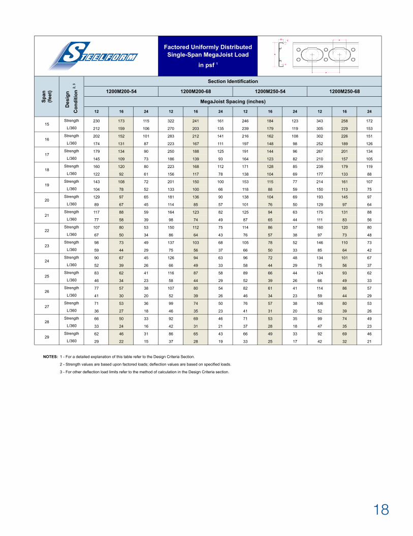
Strength 230 173 115 322 241 161 246 184 123 343 258 172
L/360 212 159 106 270 203 135 239 179 119 305 229 153
Strength 202 152 101 283 212 141 216 162 108 302 226 151
L/360 174 131 87 223 167 111 197 148 98 252 189 126
Strength 179 134 90 250 188 125 191 144 96 267 201 134
L/360 145 109 73 186 139 93 164 123 82 210 157 105
Strength 160 120 80 223 168 112 171 128 85 239 179 119
L/360 122 92 61 156 117 78 138 104 69 177 133 88
Strength 143 108 72 201 150 100 153 115 77 214 161 107
L/360 104 78 52 133 100 66 118 88 59 150 113 75
Strength 129 97 65 181 136 90 138 104 69 193 145 97
L/360 89 67 45 114 85 57 101 76 50 129 97 64
Strength 117 88 59 164 123 82 125 94 63 175 131 88
L/360 77 58 39 98 74 49 87 65 44 111 83 56
Strength 107 80 53 150 112 75 114 86 57 160 120 80
L/360 67 50 34 86 64 43 76 57 38 97 73 48
Strength 98 73 49 137 103 68 105 78 52 146 110 73
L/360 59 44 29 75 56 37 66 50 33 85 64 42
Strength 90 67 45 126 94 63 96 72 48 134 101 67
L/360 52 39 26 66 49 33 58 44 29 75 56 37
Strength 83 62 41 116 87 58 89 66 44 124 93 62
L/360 46 34 23 58 44 29 52 39 26 66 49 33
Strength 77 57 38 107 80 54 82 61 41 114 86 57
L/360 41 30 20 52 39 26 46 34 23 59 44 29
Strength 71 53 36 99 74 50 76 57 38 106 80 53
L/360 36 27 18 46 35 23 41 31 20 52 39 26
Strength 66 50 33 92 69 46 71 53 35 99 74 49
L/360 33 24 16 42 31 21 37 28 18 47 35 23
Strength 62 46 31 86 65 43 66 49 33 92 69 46
L/360 29 22 15 37 28 19 33 25 17 42 32 21
NOTES: 1 - For a detailed explanation of this table refer to the Design Criteria Section.
2 - Strength values are based upon factored loads; deflection values are based on specified loads.
3 - For other deflection load limits refer to the method of calculation in the Design Criteria section.
Factored Uniformly Distributed Single-Span MegaJoist Load
in psf 1
Span
(feet
)
Des
ign
Con
ditio
n 2,
3
Section Identification
1200M200-54 1200M200-68 1200M250-54 1200M250-68
MegaJoist Spacing (inches)
15
16
17
18
19
20
21
22
23
24
25
26
27
28
29
18

12 16 24 12 16 24 12 16 24 12 16 24
Strength 220 165 110 314 236 157 188 141 94 275 206 138
L/360 225 169 112 283 212 141 217 163 109 281 211 141
Strength 199 149 100 278 209 139 171 128 85 244 183 122
L/360 187 141 94 236 177 118 181 136 91 235 176 117
Strength 178 133 89 248 186 124 152 114 76 217 163 109
L/360 158 118 79 199 149 99 153 114 76 198 148 99
Strength 159 120 80 223 167 111 136 102 68 195 146 98
L/360 134 101 67 169 127 84 130 97 65 168 126 84
Strength 144 108 72 201 151 101 123 92 62 176 132 88
L/360 115 86 58 145 109 72 111 83 56 144 108 72
Strength 130 98 65 182 137 91 112 84 56 160 120 80
L/360 99 75 50 125 94 63 96 72 48 124 93 62
Strength 119 89 59 166 125 83 102 76 51 145 109 73
L/360 86 65 43 109 82 54 84 63 42 108 81 54
Strength 109 82 54 152 114 76 93 70 47 133 100 67
L/360 76 57 38 95 71 48 73 55 37 95 71 47
Strength 100 75 50 140 105 70 86 64 43 122 92 61
L/360 67 50 33 84 63 42 64 48 32 83 63 42
Strength 92 69 46 129 97 64 79 59 39 113 85 56
L/360 59 44 29 74 56 37 57 43 28 74 55 37
Strength 85 64 43 119 89 59 73 55 36 104 78 52
L/360 52 39 26 66 49 33 51 38 25 66 49 33
Strength 79 59 39 110 83 55 68 51 34 97 72 48
L/360 47 35 23 59 44 29 45 34 23 59 44 29
Strength 73 55 37 103 77 51 63 47 31 90 67 45
L/360 42 31 21 53 40 26 41 30 20 53 39 26
Strength 68 51 34 96 72 48 59 44 29 84 63 42
L/360 38 28 19 48 36 24 36 27 18 47 35 24
Strength 64 48 32 89 67 45 55 41 27 78 59 39
L/360 34 26 17 43 32 21 33 25 16 43 32 21
NOTES: 1 - For a detailed explanation of this table refer to the Design Criteria Section.
2 - Strength values are based upon factored loads; deflection values are based on specified loads.
3 - For other deflection load limits refer to the method of calculation in the Design Criteria section.
Factored Uniformly Distributed Single-Span MegaJoist Load
in psf 1
Span
(feet
)
Des
ign
Con
ditio
n 2,
3
Section Identification
1200M300-54 1200M300-68 1400M162-54 1400M162-68
MegaJoist Spacing (inches)
16
17
18
19
20
21
22
23
24
25
26
27
28
29
30
19

12 16 24 12 16 24 12 16 24 12 16 24
Strength 167 126 84 254 191 127 167 126 84 274 206 137
L/360 174 130 87 223 167 112 196 147 98 252 189 126
Strength 159 119 79 228 171 114 159 119 79 246 184 123
L/360 148 111 74 190 142 95 167 125 83 214 160 107
Strength 146 109 73 206 154 103 151 113 75 222 167 111
L/360 127 95 63 163 122 81 143 107 71 183 138 92
Strength 132 99 66 187 140 93 143 107 71 201 151 101
L/360 109 82 55 141 105 70 124 93 62 158 119 79
Strength 121 90 60 170 128 85 130 98 65 183 138 92
L/360 95 71 48 122 92 61 107 81 54 138 103 69
Strength 110 83 55 156 117 78 119 89 60 168 126 84
L/360 83 62 42 107 80 54 94 71 47 121 90 60
Strength 101 76 51 143 107 71 109 82 55 154 116 77
L/360 73 55 37 94 71 47 83 62 41 106 80 53
Strength 93 70 47 132 99 66 101 76 50 142 107 71
L/360 65 49 32 83 63 42 73 55 37 94 70 47
Strength 86 65 43 122 91 61 93 70 47 131 99 66
L/360 58 43 29 74 56 37 65 49 33 83 63 42
Strength 80 60 40 113 85 56 86 65 43 122 91 61
L/360 52 39 26 66 50 33 58 44 29 75 56 37
Strength 74 56 37 105 79 53 80 60 40 113 85 57
L/360 46 35 23 59 44 30 52 39 26 67 50 33
Strength 69 52 35 98 73 49 75 56 37 106 79 53
L/360 42 31 21 53 40 27 47 35 23 60 45 30
Strength 65 49 32 91 69 46 70 53 35 99 74 49
L/360 38 28 19 48 36 24 42 32 21 54 41 27
Strength 61 46 30 86 64 43 66 49 33 92 69 46
L/360 34 26 17 44 33 22 38 29 19 49 37 25
Strength 57 43 28 80 60 40 62 46 31 87 65 43
L/360 31 23 15 40 30 20 35 26 17 45 34 22
NOTES: 1 - For a detailed explanation of this table refer to the Design Criteria Section.
2 - Strength values are based upon factored loads; deflection values are based on specified loads.
3 - For other deflection load limits refer to the method of calculation in the Design Criteria section.
Factored Uniformly Distributed Single-Span MegaJoist Load
in psf 1
Span
(feet
)
Des
ign
Con
ditio
n 2,
3
Section Identification
1400M200-54 1400M200-68 1400M250-54 1400M250-68
MegaJoist Spacing (inches)
18
19
20
21
22
23
24
25
26
27
28
29
30
31
32
20

12 16 24 12 16 24 12 16 24 12 16 24
Strength 159 119 79 258 193 129
L/360 174 130 87 231 173 116
Strength 151 113 75 233 175 116
L/360 149 112 74 198 149 99
Strength 143 108 72 211 158 106
L/360 129 96 64 171 128 86
Strength 137 103 68 192 144 96
L/360 112 84 56 149 112 75
Strength 125 94 63 176 132 88
L/360 98 73 49 130 98 65
Strength 115 86 57 162 121 81
L/360 86 65 43 115 86 57
Strength 106 79 53 149 112 75
L/360 76 57 38 102 76 51
Strength 98 73 49 138 103 69
L/360 68 51 34 90 68 45
Strength 91 68 45 128 96 64
L/360 61 45 30 81 60 40
Strength 84 63 42 119 89 59
L/360 54 41 27 72 54 36
Strength 79 59 39 111 83 55
L/360 49 37 24 65 49 33
Strength 74 55 37 103 78 52
L/360 44 33 22 59 44 29
Strength 69 52 34 97 73 48
L/360 40 30 20 53 40 27
Strength 65 48 32 91 68 45
L/360 36 27 18 48 36 24
Strength 61 46 30 86 64 43
L/360 33 25 17 44 33 22
NOTES: 1 - For a detailed explanation of this table refer to the Design Criteria Section.
2 - Strength values are based upon factored loads; deflection values are based on specified loads.
3 - For other deflection load limits refer to the method of calculation in the Design Criteria section.
Factored Uniformly Distributed Single-Span MegaJoist Load
in psf 1
26
Span
(feet
)
Des
ign
Con
ditio
n 2,
3
Section Identification
1400M300-54 1400M300-68
MegaJoist Spacing (inches)
29
30
27
31
32
33
19
20
21
22
23
24
25
28
21