megapress tool set megapress tool set · astm a53 and asme b 36.10 astm a53 and asme b 36.10...
TRANSCRIPT

Instructions for Use
Megapress Tool Setfor Megapress Press-In Connections
US
Model Model year
4878.5 as from 03/2016
Instructions for Use
MegaPress Tool Setfor MegaPress press-in branch connector
12/03/2018

Viega products are designed to be installed by licensed and trained plumbing and mechanical professionals who are familiar with Viega products and their installation. Installation by non-professionals may void Viega LLC’s warranty.

Table of contents
3
US
TABLE OF CONTENTS
1 About this instruction for use 5
1.1 Target groups 5
1.2 Labeling of notes 5
2 Product information 6
2.1 Intended use 62.1.1 Areas of use 6
2.2 Product description 102.2.1 Press-in branch connector 102.2.2 Tool set 10
2.3 Compatible pipes 142.3.1 Component marking 16
2.4 Accessories and spare parts 17
3 Handling 19
3.1 Safety advice 19
3.2 Assembly information 203.2.1 Space requirements and distances 203.2.2 Required tools 24
3.3 Assembly 263.3.1 Preparing pipes 263.3.2 Creating the drill hole 283.3.3 Mounting press-in branch connector with
press-in tool 373.3.4 Additional use of press-in branch connector 43

MegaPress Tool Set
4
3.4 Commissioning 443.4.1 Leakage test 44
3.5 Care and maintenance 453.5.1 Cleaning 453.5.2 Maintenance intervals 463.5.3 Replacing the hole saw 473.5.4 Replacing pilot bit 493.5.5 Replacing mount for drilling machine 50
3.6 Disposal 52
4 Viega MegaPress Limited Warranty 53

5
About this instruction for use | Target groups
US
1 About this instruction for use
1.1 Target groupsThe information in this manual is directed at HVAC and plumbing profes-sionals as well as other trained specialist personnel.
The installation of Viega products must take place in accordance with the best practices of engineering and the Viega instructions for use.
Individuals without the above mentioned training or qualification to mount, install and maintain, if required, are not permitted to service this product. This restriction does not extend to possible operating instructions.
These instructions for use must be kept together with the tool set.
1.2 Labeling of notesWarning and advisory texts are set apart from the remainder of the text and they are labeled with the relevant symbols.
DANGER!Danger to life and other hazards!This symbol warns against possible fatal injuries.
WARNING!Risk of injury!This symbol warns against possible serious injuries.
CAUTION!Risk of injury!This symbol warns against possible injuries.
NOTE!This symbol warns against possible damage to property.
This type of note provides additional tips.

6
MegaPress Tool Set
2 Product information
2.1 Intended use
The use of the MegaPress tool set and the MegaPress press-in branch connector for other areas of use and other media than those described herein must be approved by Viega Technical Services.
2.1.1 Areas of useThe MegaPress press-in branch connector is designed for schedule 10 and schedule 40 steel pipes. The press-in branch connector creates a threaded connection in the steel pipes. Particularly suitable where space is at a premium, e.g. in pipe manifold installation for sensors, thermometers or drains.
The press-in branch connector is not suitable for use in drinking water in-stallations.
The press-in branch connector may not be used for fuel gases according to ANSI LC4 or in combination with ProPress Stainless Steel components.
Use is possible in the following areas:
�Industrial systems
�Fire sprinkler systems
– wet– wet/dry– dry
�Compressed air systems
�Shipbuilding
�Heating and cooling systems (closed loop)
�Systems for technical gases (on request)
�Other applications pending Viega approval
7
Product information | Intended use
US
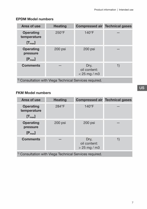
EPDM Model numbers
Area of use Heating Compressed air Technical gases
Operating temperature
[Tmax]
250°F 140°F —
Operating pressure
[Pmax]
200 psi 200 psi —
Comments — Dry, oil content:
< 25 mg / m3
1)
1) Consultation with Viega Technical Services required.
FKM Model numbers
Area of use Heating Compressed air Technical gases
Operating temperature
[Tmax]
284°F 140°F —
Operating pressure
[Pmax]
200 psi 200 psi —
Comments — Dry, oil content:
> 25 mg / m3
1)
1) Consultation with Viega Technical Services required.
8
MegaPress Tool Set
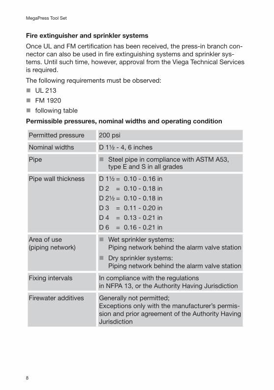
Fire extinguisher and sprinkler systems
Once UL and FM certification has been received, the press-in branch con-nector can also be used in fire extinguishing systems and sprinkler sys-tems. Until such time, however, approval from the Viega Technical Services is required.
The following requirements must be observed:
�UL 213
�FM 1920
�following table
Permissible pressures, nominal widths and operating condition
Permitted pressure 200 psi
Nominal widths D 1½ - 4, 6 inches
Pipe �Steel pipe in compliance with ASTM A53, type E and S in all grades
Pipe wall thickness D 1½ = 0.10 - 0.16 inD 2 = 0.10 - 0.18 inD 2½ = 0.10 - 0.18 inD 3 = 0.11 - 0.20 inD 4 = 0.13 - 0.21 inD 6 = 0.16 - 0.21 in
Area of use (piping network)
�Wet sprinkler systems: Piping network behind the alarm valve station
�Dry sprinkler systems: Piping network behind the alarm valve station
Fixing intervals In compliance with the regulations in NFPA 13, or the Authority Having Jurisdiction
Firewater additives Generally not permitted; Exceptions only with the manufacturer’s permis-sion and prior agreement of the Authority Having Jurisdiction
9
Product information | Intended use
US
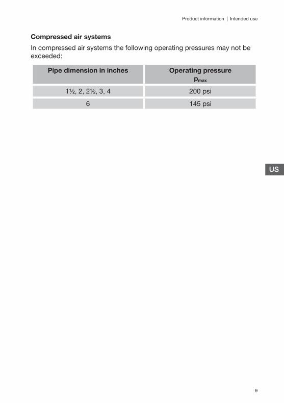
Compressed air systems
In compressed air systems the following operating pressures may not be exceeded:
Pipe dimension in inches Operating pressure pmax
1½, 2, 2½, 3, 4 200 psi
6 145 psi

10
MegaPress Tool Set
2.2 Product descriptionVarious components and tools are required to create a press-in branch con-nector.
2.2.1 Press-in branch connector
A separate press-in branch connector is available for the different pipe dimensions. The press-in branch con-nector is fitted with a sealing element made of EPDM or FKM.
The sealing element may not be replaced.
The press-in branch connector has an external zinc nickel coating and it is suitable for schedule 10 and schedule 40 steel pipes according to ASTM A53, see Chapter “Compatible pipes” on Page 14. The press-in branch con-nector is available with a ¾" internal NPT thread in accordance with ASME B1.20.1.
2.2.2 Tool set
1 - Positioning aids (D 1½ - 4, 6 inch)
2 - Press-in tool3 - Installer swage for press-in tool4 - Drilling shaft5 - Drilling device for guiding drilling
shaft6 - Instructions for use7 - Marking penThe tool set (part number 26920) for the press-in branch connector is available in a case.

11
Product information | Product description
US
Drilling device with tension chain for guiding drilling shaft
1 - Guide for drilling shaft2 - Vacuum cleaner connection 1¼
in.3 - Tension nut4 - Tension chain5 - Milled recess as marking for sub-
sequent alignment
Drilling shaft
1 - Drilling shaft with hexagonal drive
2 - 11/16" hole saw3 - Pilot bit4 - Guide boltAlternatively, the hexagonal drive can also be replaced by an SDS plus mount. We recommend that you use the hexagonal drive here.
12
MegaPress Tool Set
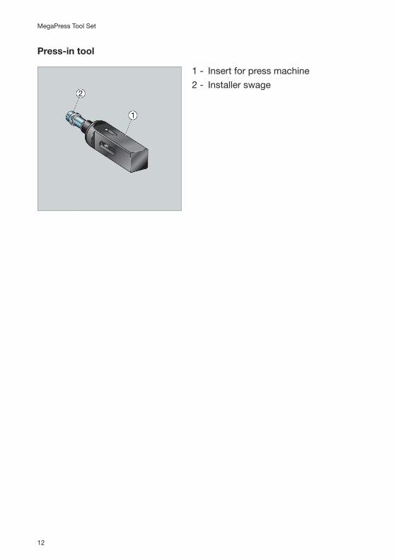
Press-in tool
1 - Insert for press machine2 - Installer swage

13
Product information | Product description
US
Positioning aid D 1½-2½ inches and D 3, 4 and 6 inches
The positioning aids are to be used for mounting the individual press-in branch connectors. A separate positioning aid is available for each pipe dimension.
The nominal outer diameter is specified on the positioning aid in both inches and millimeters.
Positioning aid D 1½-2½ inches1 - Handle2 - Markings help to mark out addi-
tional press-in branch connectors around the circumference of the pipe
3 - Recess for key surface on press-in branch connector
4 - Pipe template. The correct pipe dimension can be checked using the positioning aid
Positioning aid D 3, 4 and 6 inches1 - Handle2 - Markings help to mark out addi-
tional press-in branch connectors around the circumference of the pipe
3 - Recess for key surface on press-in branch connector
4 - Pipe template. The correct pipe dimension can be checked using the positioning aid

14
MegaPress Tool Set
2.3 Compatible pipes
The information in this chapter is not applicable to sprinkler sys-tems, Ä Chapter “Fire extinguisher and sprinkler systems” on Page 8.
The press-in branch connector can be used with the following seamless steel pipes or steel pipes welded along the longitudinal seam:
�black
�galvanized
�industrially painted
�powder coated
The steel pipes must comply with the following standard:
�All pipe in accordance with ASTM A53
To ensure proper operation, the correct press-in branch connector for the given pipe dimension and correct schedule of pipe must be used. If this requirement is not met, leaks and malfunctions may occur.
Observe the specified tolerances for the pipe wall thicknesses

15
Product information | Compatible pipes
US
ASTM A53 and ASME B 36.10
ASTM A53 and ASME B 36.10 differentiate between schedules and set tol-erances for standard steel pipe. The table below is a summary of accept-able dimensions.
Press-in branch
connector part
number
¾
For pipe dimen-
sion
Nominal external diame-
ter
External diameter Wall thick-
ness for sched-ule 10
Wall thick-
ness for sched-ule 40
Inch inches min. inches
max. inches
inches inches
1½ 1.900 1.884 1.916 0.109 0.145
2 2.375 2.359 2.391 0.109 0.154
2½ 2.875 2.859 2.891 0.120 0.203
3 3.500 3.484 3.516 0.120 0.216
4 4.500 4.484 4.516 0.120 0.237
6 6.625 6.609 6.641 0.134 0.280
16
MegaPress Tool Set
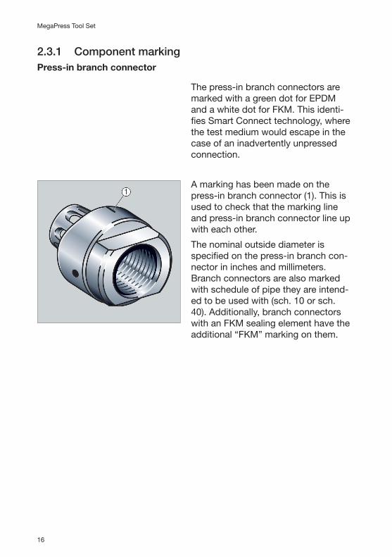
2.3.1 Component markingPress-in branch connector
The press-in branch connectors are marked with a green dot for EPDM and a white dot for FKM. This identi-fies Smart Connect technology, where the test medium would escape in the case of an inadvertently unpressed connection.
A marking has been made on the press-in branch connector (1). This is used to check that the marking line and press-in branch connector line up with each other.
The nominal outside diameter is specified on the press-in branch con-nector in inches and millimeters. Branch connectors are also marked with schedule of pipe they are intend-ed to be used with (sch. 10 or sch. 40). Additionally, branch connectors with an FKM sealing element have the additional “FKM” marking on them.

17
Product information | Accessories and spare parts
US
2.4 Accessories and spare partsVarious matching accessories and spare parts are available for the tool set:
Hole Saw
The hole saw’s outside diameter is 11/16".
We recommend that you use the fol-lowing spare hole saws (outside di-ameter 11/16"):
�Equivalent Ridgid article
Worn hole saws may not be used, as by doing so the drill hole will not be circular or it may be too small, which in turn means that the press-in branch connector can no longer be fitted into place.
Hole saws and the drilling device are matched to each other. If other hole saws are used, the leak tightness can no longer be as-sured.

18
MegaPress Tool Set
Pilot Bit
The pilot bit has a diameter of ¼", a length of 3¾" and it is flattened at the mounting surface. This flattening off helps to fasten the pilot bit firmly in place.
We recommend that you use the Viega pilot bit. Alternatively, HSS drills acc. to ANSI/ASME B94.11M-1993 with flattened off mounting surface may be used.
SDS-plus drill mount
If you are using a drill equipped with an SDS-plus drill chuck, an SDS-plus mount is available for purchase in-stead of using the hexagonal drive adapter.

19
Handling | Safety advice
US
3 Handling
3.1 Safety advice
– The applicable accident-prevention regulations are relevant for all work conducted.
– Safety goggles and suitable hand protectors must be used.
Mandatory labels
Note the mandatory labels and warning signs affixed to the drill guide:
General warning signs
Follow instructions for use
Wear head protection
Wear eye protection
Transport and storage
�To protect the tools against damage or loss, always transport them in the designated cases only.
�Store case and tools dry and clean at all times.
Safety when drilling
�Before using the tool, always check that it operates properly and smoothly. Do not use damaged components. Use undamaged original system parts only.
�Tools or individual components may be damaged if dropped. Drill ma-chines that have been dropped may not be used. They have to be re-placed or sent to a service station for inspection.
�Before drilling, completely drain the pipelines and depressurize them.

20
MegaPress Tool Set
�Note minimum distances specified for the tools, Ä Chapter 3.2.1 “Space requirements and distances” on Page 20.
�Filings are created when drilling. Always wear suitable safety goggles.
�The hole saw, pilot bit and coupon can get very hot. Allow parts to cool down after drilling is finished. Use suitable hand protectors to dismantle the parts. Do not place hot parts onto combustible materials.
�Follow the safety instructions in the drill machine and suction device manual.
Maintenance
�Follow maintenance, repair and care instructions.
�All maintenance and repair work is to be conducted by Viega-autho-rized service companies only.
3.2 Assembly information
3.2.1 Space requirements and distances
CAUTION!Risk of injury due to insufficient distances.If, when mounting the press-in branch connector, the necessary minimum distances are not met, personal injuries and damage to other components may occur.
After mounting the press-in branch connector, the branch connector must not have any thermal loads applied to it, e.g. through welding work, that have higher temperatures than the approved maximum permissible operat-ing temperature. If the pipeline is to be bent at a later stage, the press-in branch connector may not be located in the bending area. Maintain a mini-mum distance of 0.5 x pipe outside diameter to the bending area.
We recommend that you always check the space requirements before drill-ing. Connectors, clamps, etc., may not be installed in the area of the bore hole. Keep a distance of 2" so that you can properly mount the positioning and drilling device.
Minimum distances are available in the corresponding section of the table.

21
Handling | Assembly information
US
Minimum distances for drill machine, press machine and positioning aid
The working area A is dependent on the drill machine used. Area A is made up from the length of the drill machine plus the length of the drilling shaft (6.69").
Working area B is the length of the press machine (including 0.79" working travel) with the press-in tool and press-in branch connector.
Press machine Working area B
Ridgid CT 400 20.5"
Ridgid RP 320-E 16.5"
Ridgid RP 330-B/C 17.3"
Ridgid RP 340 15.5"
The minimum distances c, d and e must be complied with for mounting the drilling device and the positioning aid.
Dimension in inches
Minimum distance c in inches
Minimum distance d in inches
Minimum distance e in inches
1 ½ 1.18 4.33 1.18
2 1.18 4.33 1.18
2 ½ 1.18 4.33 1.18
3 1.38 4.33 1.38
4 1.57 4.33 1.57
6 2.17 5.71 2.17
22
MegaPress Tool Set
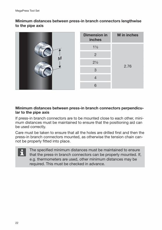
Minimum distances between press-in branch connectors lengthwise to the pipe axis
Dimension in inches
M in inches
1½
2.76
2
2½
3
4
6
Minimum distances between press-in branch connectors perpendicu-lar to the pipe axis
If press-in branch connectors are to be mounted close to each other, mini-mum distances must be maintained to ensure that the positioning aid can be used correctly.
Care must be taken to ensure that all the holes are drilled first and then the press-in branch connectors mounted, as otherwise the tension chain can-not be properly fitted into place.
The specified minimum distances must be maintained to ensure that the press-in branch connectors can be properly mounted. If, e.g. thermometers are used, other minimum distances may be required. This must be checked in advance.

23
Handling | Assembly information
US
The minimum distance N relates to the angle of the press-in branch con-nectors to each other. It is indicated in degrees in the table.
Dimen-sion in inches
N Symbol
1½
180°2
2½
3
90°4
6

24
MegaPress Tool Set
3.2.2 Required toolsThe following machines are required for processing the press-in branch con-nector:
�Drill machine/hammer drill
�Press machine
�Suction device, e.g. shop vacuum
�Marking pen
�27 mm metric or adjustable wrench
�32 mm metric or adjustable wrench
�Screwdriver
�Wire brush
�Sandpaper (180 grit)
�Where applicable, pipe gripper
Drill machine or hammer drill
Commercially available drill machines or hammer drills can be used for the drilling shaft. We recommend the use of high-performance machines. When using a cordless drill, the drilling period lasts significantly longer.
Drill machines or hammer drills will be known from here onward as drill machines.
Drill machines must meet the following specifications at least:
�Power consumption: ≥ 600 watt
�Maximum drilling speed: 1200 rpm
�Drill chuck: SDS-plus or hexagonal drive
�Impact hammer function: The machine must be able to switch off the hammer impact function
�Torque limiter: Machine must be equipped with a torque limiter
NOTE!The hammer impact function must be switched off.Use properly operating, true-running drill machines only. The correct speed is a very important factor for the service life of the hole saw.
25
Handling | Assembly information
US
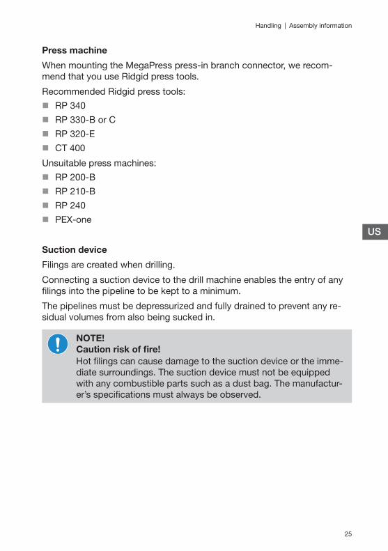
Press machine
When mounting the MegaPress press-in branch connector, we recom-mend that you use Ridgid press tools.
Recommended Ridgid press tools:
�RP 340
�RP 330-B or C
�RP 320-E
�CT 400
Unsuitable press machines:
�RP 200-B
�RP 210-B
�RP 240
�PEX-one
Suction device
Filings are created when drilling.
Connecting a suction device to the drill machine enables the entry of any filings into the pipeline to be kept to a minimum.
The pipelines must be depressurized and fully drained to prevent any re-sidual volumes from also being sucked in.
NOTE!Caution risk of fire!Hot filings can cause damage to the suction device or the imme-diate surroundings. The suction device must not be equipped with any combustible parts such as a dust bag. The manufactur-er’s specifications must always be observed.

26
MegaPress Tool Set
To enable the filings to be suctioned off, the following specifications for the suction device must be met:�Type: Industrial vacuum cleaner�Power consumption: ≥1200 watt or 10 amps�Air volume: ≥ 105 CFM�Vacuum: ≥ 80 inches of water column�Connection fitting size: 1¼"�Commercially available adapters to 1¼" can be used for other connec-
tion sizes.
3.3 AssemblyGeneral information on linear expansion of pipelines
Pipelines expand on account of differences in temperature. If the press-in branch connector is to be used for a drain pipeline, care should be taken when selecting the hole position to ensure that the linear expansion of the drain and through pipelines only generates minor tensions on the press-in branch connector. The maximum permissible linear expansion for the through pipeline is ± 0.39".
If larger linear expansions cannot be ruled out, then use the appropriate expansion joints as well as fixed and floating points in accordance with the best practices of engineering.
3.3.1 Preparing pipesRequirements on profile seal contact surface
�The mounting surface of the press-in branch connector is at least 1.97" (B).
�The drill hole is located in the center of the mounting surface.
�The drill hole diameter is 11/16" (A).
27
Handling | Assembly
US
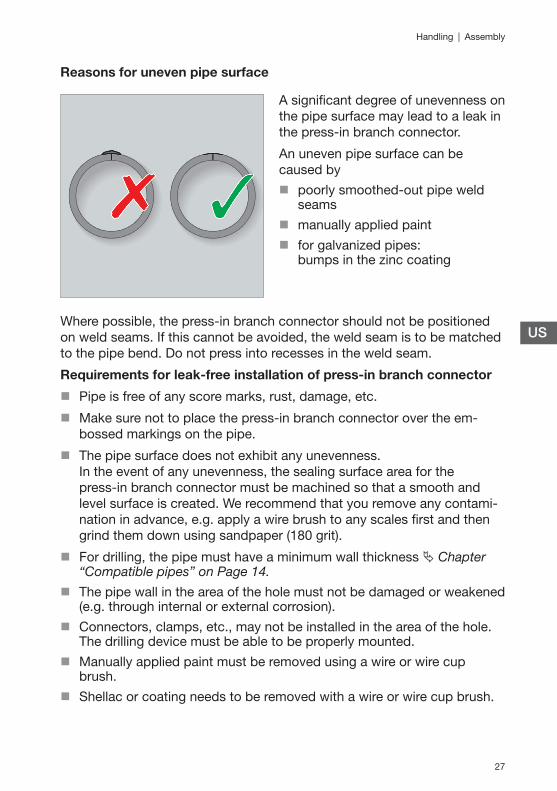
Reasons for uneven pipe surface
A significant degree of unevenness on the pipe surface may lead to a leak in the press-in branch connector.
An uneven pipe surface can be caused by
�poorly smoothed-out pipe weld seams
�manually applied paint
�for galvanized pipes: bumps in the zinc coating
Where possible, the press-in branch connector should not be positioned on weld seams. If this cannot be avoided, the weld seam is to be matched to the pipe bend. Do not press into recesses in the weld seam.
Requirements for leak-free installation of press-in branch connector
�Pipe is free of any score marks, rust, damage, etc.
�Make sure not to place the press-in branch connector over the em-bossed markings on the pipe.
�The pipe surface does not exhibit any unevenness. In the event of any unevenness, the sealing surface area for the press-in branch connector must be machined so that a smooth and level surface is created. We recommend that you remove any contami-nation in advance, e.g. apply a wire brush to any scales first and then grind them down using sandpaper (180 grit).
�For drilling, the pipe must have a minimum wall thickness Ä Chapter “Compatible pipes” on Page 14.
�The pipe wall in the area of the hole must not be damaged or weakened (e.g. through internal or external corrosion).
�Connectors, clamps, etc., may not be installed in the area of the hole. The drilling device must be able to be properly mounted.
�Manually applied paint must be removed using a wire or wire cup brush.
�Shellac or coating needs to be removed with a wire or wire cup brush.

28
MegaPress Tool Set
3.3.2 Creating the drill hole
CAUTION!Risk of injuryRisk of injury through metal filings and falling machines.
– Wear safety goggles.
– Wear safety shoes.
Note on filings
Filings are created when drilling. Connecting a suction device to the drill machine enables the entry of any filings into the pipeline to be kept to a minimum.
Note on pilot bit
�A hole may not be drilled without using a pilot bit.
�Do not use a worn pilot bit.
�Do not regrind the pilot bit.
Requirements
It is important that the drill hole is properly drilled. This will ensure that the press-in branch connector can be correctly installed so that it will operate smoothly.Viega recommends the use of the tool set, part number 26920.
�If the drill hole is drilled without using the tool set (e.g. through an up-right drilling machine) the perpendicular drill hole must have an outside diameter of 1.06" ± 0.03".
�The pipe section must be depressurized and drained before drilling the hole.
�Note the following chapters before drilling the hole: Ä Chapter 3.2.1 “Space requirements and distances” on Page 20 and Ä Chapter 3.3.1 “Preparing pipes” on Page 26.
29
Handling | Assembly
US
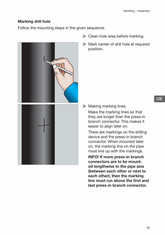
Marking drill hole
Follow the mounting steps in the given sequence.
X Clean hole area before marking.
X Mark center of drill hole at required position.
X Making marking lines.Make the marking lines so that they are longer than the press-in branch connector. This makes it easier to align later on.There are markings on the drilling device and the press-in branch connector. When mounted later on, the marking line on the pipe must line up with the markings.INFO! If more press-in branch connectors are to be mount-ed lengthwise to the pipe axis (between each other or next to each other), then the marking line must run above the first and last press-in branch connector.

30
MegaPress Tool Set
Mounting drilling device
X Unscrew tension nut in coun-ter-clockwise direction until fully open.
X Fit tension chain around pipe so that it makes contact all the way around.Mount drilling device with vacuum hose connection, facing down-ward.NOTE! For horizontal lines, the tension chain is to be routed over the top of the pipe.
X Insert the bolts of the next nearest chain link into the drilling device’s bolt mounting.NOTE! The bolts must be fully inserted into the bolt mounting. Otherwise, damage or an in-creased amount of wear may result.
31
Handling | Assembly
US
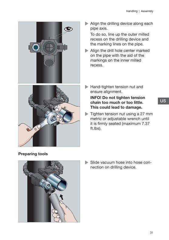
X Align the drilling device along each pipe axis.To do so, line up the outer milled recess on the drilling device and the marking lines on the pipe.
X Align the drill hole center marked on the pipe with the aid of the markings on the inner milled recess.
X Hand-tighten tension nut and ensure alignment.INFO! Do not tighten tension chain too much or too little. This could lead to damage.
X Tighten tension nut using a 27 mm metric or adjustable wrench until it is firmly seated (maximum 7.37 ft.lbs).
Preparing tools
X Slide vacuum hose into hose con-nection on drilling device.

32
MegaPress Tool Set
X Check the hole saw and pilot bit for damage, wear and correct vertical clearance between the two (0.08"). Replace parts, if necessary.
X Check the pilot bit for firm seat; tighten if necessary.INFO!
– Use undamaged parts only.– Do not use grease and oils (e.g. cutting oil) when drilling. Otherwise, the sealing element on the press-in branch con-nector may be damaged.
X Insert drilling shaft into drilling ma-chine (SDS-plus) or clamp drilling shaft using hexagon adapter into chuck.
X Switch off hammer impact func-tion.
X Set to clockwise rotation.

33
Handling | Assembly
US
Drilling drill hole
NOTE! Do not switch on drilling machine yet! X Slide guide bolt of drilling shaft into guide on drilling device.
X Apply slight pressure to push drill-ing shaft up to stop unit in drilling device.While doing so, do not tilt the drill-ing shaft or the hole saw.
X Switch on suction device.
X Switch on drilling machine.
X Drill complete hole in a single operation.Apply some pressure while doing so.
INFO! Since the filings will need to be removed during the drilling process, the following technique should be applied:
X When drilling, occasionally release pressure on the drill by backing off at regular intervals to allow filings to be extracted and keep the bit cool.

34
MegaPress Tool Set
Ending drilling procedure
CAUTION!Risk of injury and risk of igniting combustible materials through hot hole saw or pilot bit.Allow time to cool down.
X Finish the drilling procedure once
� the pipe wall has been fully drilled through, or� the stop unit in the drilling
device has been reached.
X Only remove drilling machine with drilling shaft after the drilling shaft has stopped turning.
X Detach suction hose and use to clean out drill hole and debris inside pipe by inserting the hose into the drilling device shaft.
X Switch off suction device and place to one side.

35
Handling | Assembly
US
X Dismantle drilling device.
Concluding activities
The hole saw with the pilot bit has been designed such that — ideally — the coupon remains in the hole saw.
CAUTION! Risk of injury through slipping off or hot coupon. Allow time to cool down.
X Remove coupon from the hole saw using a screwdriver and adjustable pliers.

36
MegaPress Tool Set
CAUTION! Risk of injury! Do not reach into the drill hole.
X Use a wire brush to clean the pipe surface around the drill hole. A rotary brush can also be used.
X Break or round off any residual burrs using sandpaper or similar.The mounting surface for the seal-ing element should be smooth.INFO! The drill hole may not be subsequently filed down. A protruding burr will mean that the press-in branch connector cannot be inserted far enough into the pipe or that the sealing element may be damaged. Any leaked oil must be com-pletely cleaned up.
X Remove any applied (cooling) lubricants.

37
Handling | Assembly
US
3.3.3 Mounting press-in branch connector with press-in tool
X Remove installer swage from press-in tool.
INFO! Always select the match-ing press-in branch connector for the given pipe dimension and pipe schedule. Note marking on press-in branch connector!
X Fit press-in branch connector onto press-in tool.The key surface must make con-tact with the press-in tool: The sealing element for the press-in branch connector must face to-ward the pipe.
X Turn installer swage lightly until hand-tight.
NOTE! If this is not done, the installer drift may break off or the pressing procedure will not be conducted cor-rectly.
X Check sealing element for correct seating, cleanliness and intact-ness.
38
MegaPress Tool Set
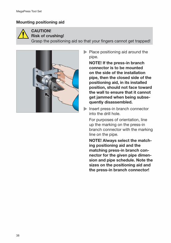
Mounting positioning aid
CAUTION!Risk of crushing!Grasp the positioning aid so that your fingers cannot get trapped!
X Place positioning aid around the pipe.NOTE! If the press-in branch connector is to be mounted on the side of the installation pipe, then the closed side of the positioning aid, in its installed position, should not face toward the wall to ensure that it cannot get jammed when being subse-quently disassembled.
X Insert press-in branch connector into the drill hole.For purposes of orientation, line up the marking on the press-in branch connector with the marking line on the pipe.NOTE! Always select the match-ing positioning aid and the matching press-in branch con-nector for the given pipe dimen-sion and pipe schedule. Note the sizes on the positioning aid and the press-in branch connector!
39
Handling | Assembly
US
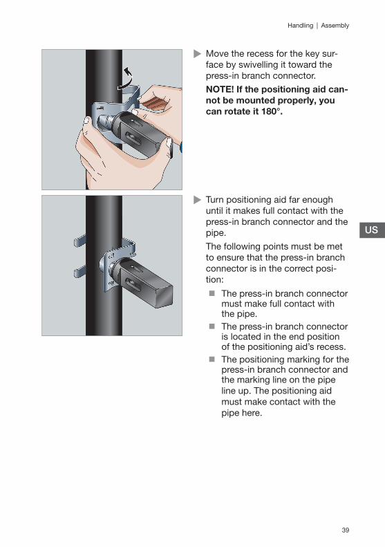
X Move the recess for the key sur-face by swivelling it toward the press-in branch connector.NOTE! If the positioning aid can-not be mounted properly, you can rotate it 180°.
X Turn positioning aid far enough until it makes full contact with the press-in branch connector and the pipe.The following points must be met to ensure that the press-in branch connector is in the correct posi-tion:
� The press-in branch connector must make full contact with the pipe.� The press-in branch connector
is located in the end position of the positioning aid’s recess. � The positioning marking for the
press-in branch connector and the marking line on the pipe line up. The positioning aid must make contact with the pipe here.

40
MegaPress Tool Set
Pressing-in press-in branch connector
X Pull out press machine’s retaining bolt.
X Slide press machine all the way up onto the press-in tool.
X Slide in retaining bolt.NOTE! Both the press-in branch connector and positioning aid must make full contact with the pipe wall.
41
Handling | Assembly
US
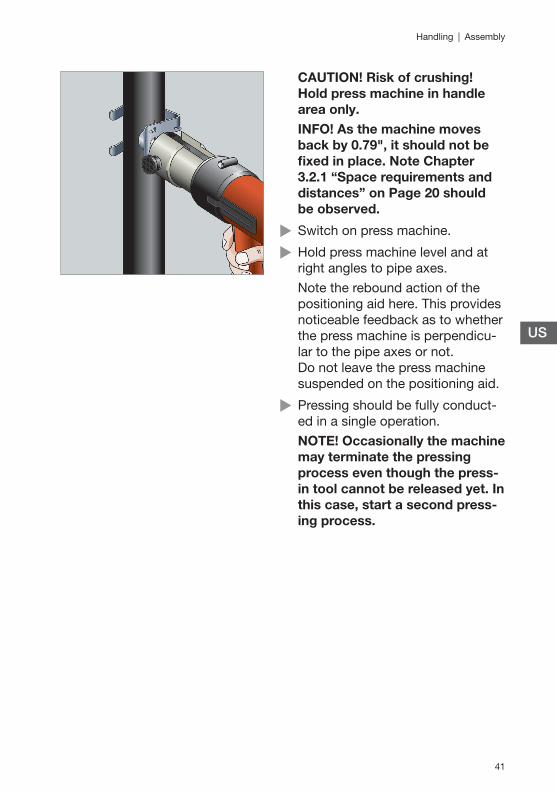
CAUTION! Risk of crushing! Hold press machine in handle area only. INFO! As the machine moves back by 0.79", it should not be fixed in place. Note Chapter 3.2.1 “Space requirements and distances” on Page 20 should be observed.
X Switch on press machine.
X Hold press machine level and at right angles to pipe axes.Note the rebound action of the positioning aid here. This provides noticeable feedback as to whether the press machine is perpendicu-lar to the pipe axes or not. Do not leave the press machine suspended on the positioning aid.
X Pressing should be fully conduct-ed in a single operation.NOTE! Occasionally the machine may terminate the pressing process even though the press-in tool cannot be released yet. In this case, start a second press-ing process.
42
MegaPress Tool Set
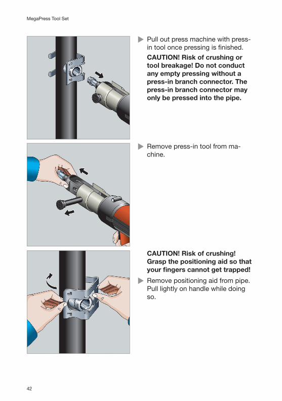
X Pull out press machine with press-in tool once pressing is finished.CAUTION! Risk of crushing or tool breakage! Do not conduct any empty pressing without a press-in branch connector. The press-in branch connector may only be pressed into the pipe.
X Remove press-in tool from ma-chine.
CAUTION! Risk of crushing! Grasp the positioning aid so that your fingers cannot get trapped!
X Remove positioning aid from pipe. Pull lightly on handle while doing so.

43
Handling | Assembly
US
Z The press-in branch connector is properly mounted and it can now be used.
Alignment afterward is not permitted!If you screw an external thread into the press-in branch connec-tor, you must counterhold the key surface using a suitable tool (e.g. 32 mm metric or adjustable wrench).After completing the installation, perform a leakage test, Ä Chapter 3.4.1 “Leakage test” on Page 44.
3.3.4 Additional use of press-in branch connectorThe NPT thread can be used for the installation of thermometers, tempera-ture sensors, manometers or drains.
It is also possible to connect pipelines, e.g. for subsequent radiator con-nections.
We recommend that you use Viega piping systems for this.
NOTE!If the connected pipeline has to be aligned again afterward, then only the pipeline may be aligned. The press-in branch connector may not have any temporary or permanent mechanical load applied to it during the alignment pro-cedure.
44
MegaPress Tool Set
3.4 Commissioning
3.4.1 Leakage testThe installer must perform a leakage test (load and leakage test) before commissioning.
The best practices of engineering must be observed.
The requirements for drinking water installations serve as the basis for the Authority Having Jurisdiction and its local codes and regulations must be complied with.
The leakage test should also be conducted in non-drinking water installa-tions in accordance with these regulations.
The result must be documented.
To prevent corrosion, the system must remain full of water after the leakage test has been performed.
Flushing system
After the leakage test the system is to be flushed in accordance with the acknowledged rules of engineering and with AHJ regulations.

45
Handling | Care and maintenance
US
3.5 Care and maintenance
3.5.1 CleaningTo ensure permanent and proper operation, the tool must be cleaned at regular intervals.
Cleaning agent:
�Clean cotton cloth
�Maintenance oil (WD 40)
Do not use silicone oil!
Drilling device including tension chain
X Use cloth and maintenance oil to clean inside and outside of drilling device.

46
MegaPress Tool Set
Drilling shaft including hole saw
X Use cloth and maintenance oil to clean outside of bearing and hole saw.
3.5.2 Maintenance intervalsFunctional safety is primarily dependent on the operational safety of the individual tools. The tools are subject to wear and tear. This is why the tools must undergo regular maintenance.
Hole saw and pilot bit
The hole saw and pilot bit must be replaced by the user as soon as any signs of wear appear. When properly used, the Viega components can reach the following number of drilled holes:
Hole saw If mainly used on pipes with minimum wall thickness of 0.09"
Approx.100 drilled holes
Hole saw If mainly used on pipes with maximum wall thickness of 0.21"
Approx. 30 drilled holes
Pilot bit Approx. 80 drilled holes
Drilling device, drilling shaft, press-in tool
Maintenance and repair work on the tools may only be conduct-ed by Viega-authorized service stations.
The components must be serviced every 2 years.
47
Handling | Care and maintenance
US
Positioning aid
The positioning aid is maintenance free. It has to be replaced if it no longer functions satisfactorily or if it is damaged.
3.5.3 Replacing the hole sawThe hole saw should be replaced when the following signs appear:
�if the drilling effect diminishes (e.g. if the applied force required when drilling increases)
�if teeth are damaged or badly worn.
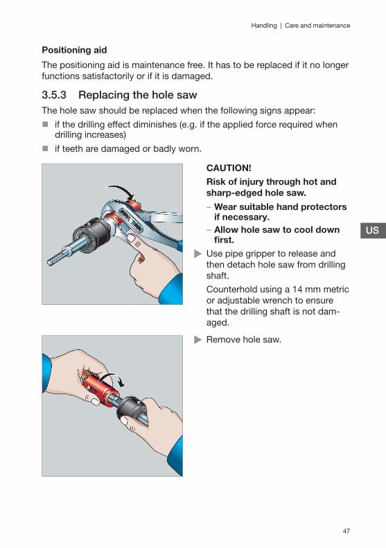
CAUTION!Risk of injury through hot and sharp-edged hole saw.
– Wear suitable hand protectors if necessary.– Allow hole saw to cool down first.
X Use pipe gripper to release and then detach hole saw from drilling shaft.Counterhold using a 14 mm metric or adjustable wrench to ensure that the drilling shaft is not dam-aged.
X Remove hole saw.

48
MegaPress Tool Set
X Apply lubricant to drilling shaft’s fine-pitch thread for every change. This makes it easier to release the drilling shaft later on.It is OK to use lubricants that contain MoS2 or graphite. If the thread is damaged, the drilling shaft or the hole saw may no longer be used.
X Mount new hole saw and tighten by hand up to stop unit.Do not tilt hole saw when screwing it in.
Z The adapter will tighten inde-pendently during the next drilling procedure.

49
Handling | Care and maintenance
US
3.5.4 Replacing pilot bitThe pilot bit must be replaced as soon as any signs of wear appear.
CAUTION!Risk of injury through hot hole saw.– Wear suitable hand protectors if necessary.
– Allow hole saw to cool down first.
X Remove fixing screw of pilot bit using Allen key (4 mm).
X Remove pilot bit.
X Slide new pilot bit far enough into drilling shaft so that it protrudes by ⅛" out of the hole saw.Rotate pilot bit far enough around its axis so that the flattened area lines up exactly with the fixing screw.

50
MegaPress Tool Set
X Tighten fixing screw using Allen key to prevent the pilot bit from also turning during the drilling procedure.
3.5.5 Replacing mount for drilling machineThe drilling shaft is equipped with a hexagonal drive. For drilling machines with an SDS-plus mount, the hexagonal drive can be replaced by an SDS-plus mount.
X Release adapter from drilling shaft using a 17 mm metric or adjusta-ble wrench.Counterhold using a 14 mm metric or adjustable wrench to ensure that the drilling shaft is not dam-aged.

51
Handling | Care and maintenance
US
X Remove adapter.
X Apply lubricant to adapter’s fine-pitch thread for every change. This makes it easier to release the adapter later on.It is OK to use lubricants that contain MoS2 or graphite. If the thread is damaged, the adapter may no longer be used.
X Screw in adapter, and tighten by hand up to stop unit. When screwing in, make sure that the adapter is not tilted when positioned. The adapter will tight-en independently during the next drilling procedure.

52
MegaPress Tool Set
3.6 DisposalSeparate the product and packaging materials (e.g. paper, metal, plastic or non-ferrous metals) and dispose of in accordance with valid national legal requirements.

53
Viega MegaPress Limited Warranty | Disposal
US
4 Viega MegaPress Limited Warranty
Subject to the conditions and limitations in this Limited Warranty, Viega LLC (Viega) warrants to end users, installers, and distribution houses that its Viega MegaPress metal press fittings (Viega Product) with application appropriate sealing element when properly installed in non-industrial and non-marine applications and under normal conditions of use shall be free from failure caused by manufacturing defects for a period of ten (10) years from date of installation in Viega MegaPress Approved Applications for flu-ids/water, oil and lubricant, and gases under Viega specified system oper-ating conditions.
Under this Limited Warranty, you only have a right to a remedy if the failure or leak resulted from a manufacturing defect in the Viega Product and the failure or leak occurs during the warranty period. You do not have a reme-dy under this warranty and the warranty remedy does not apply if the fail-ure or any resulting damage is caused by (1) components other than those manufactured or sold by Viega, such as black iron pipe; (2) not designing, installing, inspecting, testing, or maintaining the Viega Product in accord-ance with Viega’s installation and product instructions in effect at the time of installation and other specifications and approvals applicable to the in-stallation; (3) use of Viega Product under non recommended system oper-ating conditions, improper handling and protection of the Viega Product prior to, during and after installation, inadequate freeze protection, or ex-posure to environmental conditions not recommended for the application; or (4) acts of nature, such as, but not limited to, earthquakes, fire, or weather damage. In the event of a leak or other failure of the Viega Product covered by this warranty, it is the responsibility of the end user to take ap-propriate measures to mitigate any damage, to include making timely re-pairs. Only if the warranty applies will Viega be responsible for the remedy under this warranty. The part or parts which you claim failed should be kept and Viega contacted by writing to the address below or telephoning 1-800-976-9819 within thirty (30) calendar days after the leak or other fail-ure and identifying yourself as having a warranty claim. You should be pre-pared to ship, at your expense, the product which you claim failed due to a manufacturing defect, document the date of installation, and the amount of the repair or replacement if performed by you. Within a reasonable time after receiving the product, Viega will investigate the reasons for the failure, which includes the right to inspect the product at a Viega location and rea-sonable access to the site of damage. Viega will notify you in writing as to the results of its review.

54
MegaPress Tool Set
In the event that Viega determines that the failure or leak was the result of a manufacturing defect in the Viega Product covered by this warranty and this warranty applies, the EXCLUSIVE AND ONLY REMEDY under this war-ranty shall be the reimbursement for reasonable charges for repair or re-placement of the Viega Product itself. VIEGA SHALL NOT BE LIABLE FOR ANY CONSEQUENTIAL OR OTHER DAMAGE (FOR EXAMPLE, ECONOM-IC LOSS, WATER OR PROPERTY OR MOLD REMEDIATION) UNDER ANY LEGAL THEORY AND WHETHER ASSERTED BY DIRECT ACTION, FOR CONTRIBUTION OR INDEMNITY OR OTHERWISE.
THE ABOVE WARRANTY IS IN LIEU OF ALL OTHER WARRANTIES, EX-PRESS OR IMPLIED, INCLUDING, BUT NOT LIMITED TO, THE IMPLIED WARRANTIES OF MERCHANTABILITY AND FITNESS FOR A PARTICU-LAR PURPOSE OR ANY STATUTE OF LIMITATIONS RELATING TO SUCH WARRANTIES. Other than this Limited Warranty, Viega does not authorize any person or firm to create for it any other obligation or liability in connec-tion with its products.
This Limited Warranty gives you specific legal rights and you also may have other rights which may vary from state to state. This warranty shall be interpreted and applied under the law of the state in which the product is installed and is intended as a COMMERCIAL WARRANTY.
55
Viega MegaPress Limited Warranty | Disposal
US

5994
37
12/0
3/20
18
Viega LLC
585 Interlocken Blvd. Broomfield, CO 80021
Phone (800) 976-9819
www.viega.us
V
This document is subject to updates. For the most current Viega technical literature please visit www.viega.us.