melissa – adaptation for space
TRANSCRIPT

SD063/02
H.R. GENT 165.321 - BTW BE 447.422.101 - KBC 441-0619121-21
MELiSSA – Adaptation for Space
ESA contract 15671/01/NL/ND
TECHNICAL NOTE 72.9.4
Acceptance review documentation
Version : 1 Issue : 0
Name Signature Prepared by:
Farida Doulami
Heleen De Wever
Approved by:
Dries Demey
Date 23 March 2004

SD063/02
H.R. GENT 165.321 - BTW BE 447.422.101 - KBC 441-0619121-21
DOCUMENT CHANGE LOG
Version Issue Date Observation 1 0 27/02/04 Draft 2 1 23/03/04 Final
DISTRIBUTION LIST
Quantity 2
Company/Department ESA
Name Christophe Lasseur
1 EPAS Farida Doulami Dries Demey 1 NTE Joan Mas 1 Vito Heleen De Wever
+ 3 copies library Veerle van Hoof 1 GEPEA Pascal Jaouen

TN72.9.4 ACCEPTANCE REVIEW DOCUMENTATION.DOC 3
CONTENT
1. INTRODUCTION 6
2. OVERVIEW 6
2.1 SCHEME 6
3. MATERIAL INVENTORY 7
3.1 TECHNICAL DESCRIPTION 7 3.2 NECESSARY FACILITIES 8
4. SPECIFIC OPERATION OF THE INSTRUMENTS 8
4.1 TEMPERATURE CONTROLLER TT1 8 4.2 COOLER K1, K2 & COOLER TEMPERATURE CONTROL KT1, KT2 8 4.3 MAGNETIC STIRRER R1 9 4.4 STIRRER R2 & R3 9 4.5 LIGHTING SYSTEM 9 4.6 MICRO GEAR PUMP P3 9 4.7 PERISTALTIC PUMP P1 & P2 10 4.8 BIOSEP ULTRASONIC HARVEST SYSTEM C1 & C2 10 4.9 GEAR PUMP P4 10
5. WORKING PRINCIPLES 10
5.1 ALGAE REACTOR T1 11 5.2 BUFFER TANK T2 11 5.3 CONCENTRATION TANK T3 11 5.4 MEMBRANE FILTRATION LOOP UF1 & UF2 12 5.5 BACKWASH SYSTEM 12 5.6 SAMPLING 12
6. ENDING A TEST 13
7. PERIODIC MAINTENANCE 13
7.1 PERISTALTIC PUMP 13 7.2 GROWTH REACTOR 13 7.3 HARVEST SYSTEM (SEE MANUAL) 13 7.4 MEMBRANES 14
TN72.9.4 ACCEPTANCE REVIEW DOCUMENTATION.DOC 4
8. TROUBLESHOOTING 14
9. SAFETY 14
10. EPILOGUE 15
11. COMPONENT DATA SHEETS OF THE BREADBOARD 16
12. ELECTRICAL SCHEME 28

TN72.9.4 ACCEPTANCE REVIEW DOCUMENTATION.DOC 5
LIST OF FIGURES Figure 1. Schematic overview of the breadboard..................................................................................................6
Figure 2. back side of the cooler temperature control...........................................................................................9
Figure 3. Seal connection order........................................................................................................................... 13

TN72.9.4 ACCEPTANCE REVIEW DOCUMENTATION.DOC 6
1. Introduction
In the framework of the project ‘MELISSA-Adaptation for Space’ a concept was proposed for the harvest and desalination of Arthrospira algae in the MEliSSA loop The breadboard described in this manual was constructed to demonstrate the feasibility of this concept.. The harvest is a concentration cycle consisting of 2 steps:
1. concentration of the algae suspension by ultrasonic separation 2. further concentration of the clarified stream leaving the ultrasound separation system by
ultrafiltration The washing or desalination of the algae is achieved by the dilution of the concentrated cell suspension to the original volume with distilled water followed by a next concentration cycle. The washed and concentrated cell suspension can then be further processed for food production, e.g. drying or pasteurisation. In this note, the documents related to the breadboard components, instrumentation inventory and user manual are presented. It is so, that the content of this note is the layout which will be used for the functioning of the breadboard. The user will have to follow the procedure described in the manual to start and stop the harvesting of Arthrospira platensis.
2. Overview
2.1 Scheme
Figure 1. Schematic overview of the breadboard

TN72.9.4 ACCEPTANCE REVIEW DOCUMENTATION.DOC 7
3. Material inventory
3.1 Technical description
Peristaltic pump
Micro gear pump
Temperature controller
UF membrane modules
Magnetic stirrer
Manual valve
Temperature cooler
Aerator
Stirrer
Buffer tank
Electrical valve
Lab valve
Level detector
Concentration tank
Ultrasound (US) harvest system
Gear pump
US controller
Manometer

TN72.9.4 ACCEPTANCE REVIEW DOCUMENTATION.DOC 8
Flow meter
Thermometer
Glass growth reactor with lighting system
Pressure vessel
Pressure reducer
Air control valve
3.2 Necessary facilities
• Power supply: 380VAC + N, 50Hz, 32A; • A cooled buffer tank with influent; • A receptacle to collect the permeate; • An enclosure around the installation with board: “restricted area, only for authorized persons”
(in the local language);
4. Specific operation of the instruments
4.1 Temperature controller TT1
Normal reading on the screen is the process value. When pushing on button P, the desired setpoint can be set by the ▲ or ▼ button. After 2 seconds the value is accepted. The temperature controller has a built in self-optimization function. To activate this function the ▲ and ▼ buttons must be pushed together during at least 2 seconds. The tuning will terminate automatically or can be cancelled by pushing a button.
4.2 Cooler K1, K2 & cooler temperature control KT1, KT2
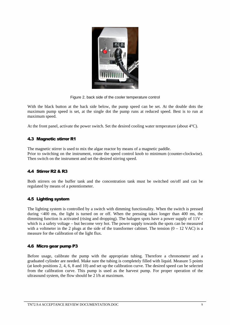
Fill the cooling vessel with tap water and glycol. The pipes towards the bioreactor and the buffer tank must be filled with water by letting the internal pump run. The pipes have manual de-aerators at the top to remove the excess air during filling. Set the red over-temperature-limiter (see Figure 2) at the back side of the cooler at a temperature higher than the process temperature.
TN72.9.4 ACCEPTANCE REVIEW DOCUMENTATION.DOC 9
Figure 2. back side of the cooler temperature control
With the black button at the back side below, the pump speed can be set. At the double dots the maximum pump speed is set, at the single dot the pump runs at reduced speed. Best is to run at maximum speed. At the front panel, activate the power switch. Set the desired cooling water temperature (about 4°C).
4.3 Magnetic stirrer R1
The magnetic stirrer is used to mix the algae reactor by means of a magnetic paddle. Prior to switching on the instrument, rotate the speed control knob to minimum (counter-clockwise). Then switch on the instrument and set the desired stirring speed.
4.4 Stirrer R2 & R3
Both stirrers on the buffer tank and the concentration tank must be switched on/off and can be regulated by means of a potentiometer.
4.5 Lighting system
The lighting system is controlled by a switch with dimming functionality. When the switch is pressed during <400 ms, the light is turned on or off. When the pressing takes longer than 400 ms, the dimming function is activated (rising and dropping). The halogen spots have a power supply of 11V - which is a safety voltage – but become very hot. The power supply towards the spots can be measured with a voltmeter in the 2 plugs at the side of the transformer cabinet. The tension (0 – 12 VAC) is a measure for the calibration of the light flux.
4.6 Micro gear pump P3
Before usage, calibrate the pump with the appropriate tubing. Therefore a chronometer and a graduated cylinder are needed. Make sure the tubing is completely filled with liquid. Measure 5 points (at knob positions 2, 4, 6, 8 and 10) and set up the calibration curve. The desired speed can be selected from the calibration curve. This pump is used as the harvest pump. For proper operation of the ultrasound system, the flow should be 2 l/h at maximum.
TN72.9.4 ACCEPTANCE REVIEW DOCUMENTATION.DOC 10
4.7 Peristaltic pump P1 & P2
Before usage, calibrate the pump with the appropriate tubing. Therefore a chronometer and a graduated cylinder are needed. Make sure the tubing is completely filled with liquid. Measure 5 points (at knob positions 2, 4, 6, 8 and 10) and set up the calibration curve. The desired speed can be selected from the calibration curve. Influent pump : The flow rate should be fixed to 3,5 ml/min for a hydraulic retention time of 24 h in the photo-bioreactor. Recirculation pump : The flow rate is dependent on the flow rate of the harvest pump and must be approximately 1,5 to 2,5 times the harvest flow rate for proper functioning of the ultrasonic separation.
4.8 Biosep Ultrasonic harvest system C1 & C2
The controller has a high frequency output to the resonance chamber where the harvest takes place. The harvest pump is controlled by the Biosep controller. Both the ultrasonic field and the harvest pump should be shut off periodically in order to facilitate the settling of aggregates in the resonance chamber. This is done by using the start and the stop timer function on the controller. The best intermittent mode should be selected by trial and error. The tables in the Biosep manual might be a rough guide. The power added to the resonance chamber can be adapted and is also subjected to experimental testing for good results. It is advisable to use low power settings because of the negative influence of thermal effects in the harvest cell. The collection chamber should be cooled by a compressed air flow by regulating V12. For further details, we refer to the manual of the Biosep system.
4.9 Gear pump P4
The gear pump, P4, is used to circulate the liquid over the membranes and to build up pressure. Speed control is done via the frequency converter (inside the cabinet). The flow can be read off the flow meter Fi1 in the membrane loop. The pressure before and after the membranes is visualized by Pi1 and Pi2.
5. Working principles
The whole installation is operated manually except for the cooling of the algae growth reactor. To start the installation, the main switch must be put on position I for operation and the reset button must be pushed. The blue operation light will then be lit. If the emergency stop is pushed, the installation will shut down completely and the red stop light will be on. Make sure that the correct plugs are in the according sockets. The cabinet with the transformators is continuously actively ventilated and will make some noise. The bioreactor and the ultrasonic resonance chamber are continuously aerated during operation. Therefore a compressed air supply must be present. The pressure reducer PR1 must be at about 0,5bar and the valves V12 and V13 must be partially open. Aeration via valve V12 is for the cooling of the harvest system and via valve 13 the algae in the bioreactor get air supply. The air-noise induced due to the opening of the valves and the apparition of bubbles in the bioreactor indicate that the aeration is in operation. Pressure reducer PR2 is set at 2 bar and serves for the backwash procedure (5.5 Backwash system).

TN72.9.4 ACCEPTANCE REVIEW DOCUMENTATION.DOC 11
5.1 Algae reactor T1
Fill the glass growth reactor with 5L of Arthrospira and switch on the magnetic stirrer R1. The installation is fed by a peristaltic pump P1 at 5 L/d for a retention time of 1 d. The growth medium (Zarrouk) enters the glass growth reactor at about the top. The growth reactor is illuminated by 56 halogen lamps. Every lamp has a radiation fraction per 1000 lx of about 5,5 W/m² in the wavelength band between 380 and 780 nm. This amount of lamps supplies a maximum light intensity of 300 W/m². However, calibration of the light intensity should be performed in the photobioreactor before operation, using a light calibrating sensor to provide a maximum Photosythetic Active Radiation (PAR) of 300 W/m2. The dichroic reflector lamps have a lifecycle of 4000 h. They have a cool light beam, which reduces the cooling necessity of the photo bioreactor. Light intensity can be reduced via a dimmer. The reaction vessel must be aerated (by V13 and PR2) continuously. The manometer of PR1 should be at approximately 0,5 bar. The algae growth reactor temperature is to be maintained at 30-35°C by the temperature controller TT1 which is connected to the cooler K1 (with its own temperature controller KT1). The lid has an opening for measurements of the pH or for sample taking. The overflow pipe discharges the excess volume in the reactor towards the buffer tank T2. Samples can be taken through an opening in the lid.
5.2 Buffer tank T2
The discharge of the bioreactor is buffered in this tank Every twenty-four hours, when the buffer has been filled with 5 L of liquid, it must be emptied into the concentration tank by manually opening valve V2. The stainless steel tank is double-walled and is cooled and stirred continuously. The stirring velocity can be adapted by means of the according potentiometer (RP1). The tank has a maximum volume of 6 l and has a transparent PMMA lid. Cooling liquid at 4°C cools the algae suspension to 4°C. Samples can be taken through an opening in the lid.
5.3 Concentration tank T3
The concentration tank is where the algae suspension will be concentrated and washed in several cycles. It must be filled with the daily collected suspension from the buffer tank and stirred continuously. The stirring velocity can be adapted by means of the according potentiometer (RP2). The vessel is made of transparent PVC. On top of the lid, the ultrasonic harvest system can be found. A low level measurement is present and a visual signal (red light on the electricity cabinet) is given when it is reached. In the ultrasonic harvest system the supernatant is separated from the algae, although the separation is not 100%. The concentrated algae suspension is returned to the concentration tank, the clear supernatant is removed via the harvest line. The circulation peristaltic pump (P2) conducts the algae into the ultrasonic harvest system and back to the concentration tank. The harvest pump P3 pumps the clarified stream to the membrane filtration unit. The resonance chamber of the ultrasound system and the harvest pump P3 are controlled by the ultrasound controller. Firstly, the algae are gathered in the concentration tank and then the circulation pump P2 must be switched on to fill the resonance chamber with the suspension. Secondly, the ultrasound controller and pump P3 can be put into operation (placed in remote instead of local control to allow the ultrasound controller to manage the functions of the ultrasound system). Then the pump P4 should be put on (see 5.4 Membrane filtration loop). When the volume in the concentration tank is reduced to below 500 ml, the low level switch (LT1) will be activated and the red low-level-alarm light will lit. The first 10-fold concentration cycle is finished. First switch off the ultrasound controller and pump P2. Then the

TN72.9.4 ACCEPTANCE REVIEW DOCUMENTATION.DOC 12
backwash procedure should be started manually. After the last concentration cycle,, the concentrate can be drained for further food processing by opening V11.
5.4 Membrane filtration loop UF1 & UF2
In the ultrafiltration loop, the supernatant coming from the concentration tank should be concentrated starting from a cell concentration of approximately 50 mg/l up to a final cell concentration of approximately 10 g/l. Two membranes with a membrane area of 0.045 m2 each are placed in series. Ceramic membranes with 3 channels, a length of 1200 mm and an outer diameter of 10 mm are used (CERAM INSIDE ATZ membranes, purchased from Tami Filtration). The permeate is drained continuously. The ultrafiltration loop is put on a slight overpressure of about 0,5 bar by relief valve R1 to prevent breakthrough of harvest through pump P3, certainly when this latter is operated at its lower capacity. The velocity of the pump P4 is controlled by a frequency converter and is visualised by flow meter Fi1. The pressure which is visualised by manometer Pi1 should not exceed 2 bar. If the pressure exceeds this limit, the ultrasound-controller and hence the micro pump P3 should be stopped. During the concentration step, valves V4, V9 and V14 are open and valves V3, V5, V10 and V15 are closed. Pump P4 keeps on running. When the volume of the concentration tank reaches 500 ml, the retentate of the filtration part must be sent back to the concentration tank and the membrane system must be backwashed with demineralised water. The aim of this demineralised water is twofold i.e. cleaning of the ultrafiltration membranes and washing of the cell suspension in the concentration tank to decrease the salt concentration of the cells. The backwash water is collected in the concentration tank until the original volume of 5 l cell suspension is reached and the next concentration cycle can start (for backwash procedure see paragraph 5.5). This procedure should be repeated several times until the salt concentration in the concentrated cell suspension is low enough. In the membrane filtration part, the liquid is circulated continuously. The supernatant of the concentration tank is sent to the filtration loop (by pump P3) and the same amount flows through the membrane pores as permeate.
5.5 Backwash system
A system for backwashing is present. First, demineralised water should be poured into the pressure vessel T4 via V6. Open the deaeration valve V7 to fill (till 4,5L) the vessel with demineralised water. Be sure to close V7 and V6 after filling. Then pressure can be built up by applying air pressure onto this vessel (open V8) and then close V8 at a pressure of about 2 bar (reading on the manometer of the pressure reducer PR2). In order to backwash, first shut down the US-controller and pump P2, then valves V3 and V5 must be opened and valves V4 and V9 must be closed whereby valve V10 remains closed. Pump P4 keeps on running. Backwash should be stopped when the volume in the concentration tank reaches 5 litres. After a backwash be sure to open valves V4 and V9 and to close V3 and V5. Several wash cycles (each one after about 2 hours 15 minutes of harvesting) are necessary whereby the wash water is drained into the concentration tank. The last time a wash cycle is executed, the resulting wash water is drained as waste by opening V10 instead of V3.
5.6 Sampling
Samples can easily be taken from the bioreactor and the buffer tank by means of a pipette. From the concentration tank a sample can be taken via valve V11. The clarified stream can be inspected by valve V15. A sample from the retentate in the filtration loop can be taken by valve V10 and the permeate sample is taken at the drain at valve V9.

TN72.9.4 ACCEPTANCE REVIEW DOCUMENTATION.DOC 13
6. Ending a test
At the end of a test cycle, the installation should be cleaned thoroughly. Make sure that the algae-reactor lights are switched off. The installation is conceived to be demounted easily. Remove the US-harvest system first. Water with a non-aggressive detergent can be used. Rinse abundantly afterwards with deminwater.
7. Periodic maintenance
7.1 Peristaltic pump
The tubes at the peristaltic pumps must be checked regularly to prevent leakage caused by the friction of the pump head.
7.2 Growth reactor
In order to remove the hoses unscrew the GL connectors. The list of the different GL connectors with seals is as follows: GL32-Ø14 (black) : aerator connection onto the lid GL14-Ø6 : connection aerator with air supply GL25-Ø10 : connection with influent GL18-Ø6 : connection for the temperature sensor Pt100 GL45-42x32 with PTFE-seal with silicon: connection with overflow pipe GL32 : cap 2 x GL32-29x16 with PTFE-seal with silicon : connection with cooling system The connection order of the seals is as in Figure 3.
Figure 3. Seal connection order
7.3 Harvest system (see manual)
No steam-in-place (SIP) cleaning procedure should be applied to the resonator chamber. Dismantle the resonator chamber from the frame by opening the tri-clamp and disconnecting the hoses. Use a pipette brush and a detergent solution to carefully clean all parts of the glass cuvette. Use caution because the glass cuvette is extremely fragile. Rinse thoroughly afterwards. The frame itself (without the cuvette) can be placed in a dishwasher. Treat the fragile transducer connections very carefully. After the rinsing, let the resonator chamber dry carefully. Ensure that the transducer contacts are completely dry before using the resonator.

TN72.9.4 ACCEPTANCE REVIEW DOCUMENTATION.DOC 14
7.4 Membranes
As described earlier (see 5.5 Backwash system), the membranes are backflushed by demineralised water after each concentration cycle. When the membranes are too much fouled, a thorough cleaning step should be applied. The fouling of the membranes can be followed by following the pressure drop over the membrane (manometers Pi1 and Pi2) as the pressure drop will increase with increasing membrane fouling. A possible chemical cleaning procedure, advised by the membrane manufacturer, is cleaning with a NaOH solution (85°C, 15-20 g/l, 30 min) followed by cleaning with HNO3 solution (50°C, 4.5 g/l, 15 min) with a clean water rinsing after each step. Experimental results showed that several washing steps were needed to fully recover the initial flux. When cleaning is necessary, the cleaning solution can be brought in the filtration loop through the demineralised water tank (open valves V8 and V5, close valve V9). During the cleaning procedure, valves V10 and V4 should be closed and valve V14 should be open. Pump P4 should be switched on. After completion of the cleaning procedure, the chemical agent can be drained from the filtration loop by opening valve V10. Additional tests should be performed on membrane cleaning to determine what is the optimal cleaning procedure and frequency.
8. Troubleshooting
9. Safety
When working with the Arthrospira harvest system the following measures should be taken into account:
• The entire manual and the manuals of the parts should be reviewed before operating the installation.
• The use, maintenance or repairing is only to be performed by qualified persons. • The installation should be connected to a proper power system of 380VAC + N tri-phase,
50Hz, 32A with sufficient grounding. • Maintenance or repairing should only be performed with the plug disconnected from the main
power system of 380VAC. • When removing or opening any parts from the system, the installation should be unplugged
from the main power. • The installation should be inspected regularly on correct functioning by qualified persons. • General laboratory safety conditions should be applied : wear safety goggles, laboratory
gloves, lab coat, safety shoes. • An enclosure must be placed around the installation with a board : “restricted area, only for
authorized persons” (in the local language).

TN72.9.4 ACCEPTANCE REVIEW DOCUMENTATION.DOC 15
10. Epilogue
This manual has been written for the Arthrospira harvest installation for the partners in the MSA project. It remains the spiritual property of Vito (Flemish Institute for Technological Research) and can not be copied, passed to neither submitted for perusal to third parties without written permission from Vito.
Mol, 2004-01-27

TN72.9.4 ACCEPTANCE REVIEW DOCUMENTATION.DOC 16
11. Component data sheets of the breadboard
Component Data Sheet
Made by: EPAS Checked by: Project ref: Melissa3 - L2356 Document ref : Issue date: 2004-03-23 Revision date : Component reference KT1- KT2 Description Cooling bath temperature control
Type C10
Sub-type 003-509
Model Number 1200301018058
Manufacturer Thermo Haake
Sales office Glasatelier Saillart
Function Controls the bath cooler temperature
Remarks
General Characteristics
Power source Electricity Protection Class (IP) 30 Voltage (V) 230 Dimension (mm) Power input (W) 1550 Weight (kg) Power output (W) Design Pressure (bar) Current draw (A) Design Temperature (°C) 20 Fuse protection (A) 2 x 8A Safety instructions
Specific Characteristics Body materials
Sealing materials
Connector type
Connector size
Document references Component drawing Certificates Input/output list Guarantee period Electric Wiring Diagram Guarantee documents Warning symbols Manual reference
TN72.9.4 ACCEPTANCE REVIEW DOCUMENTATION.DOC 17
Component Data Sheet
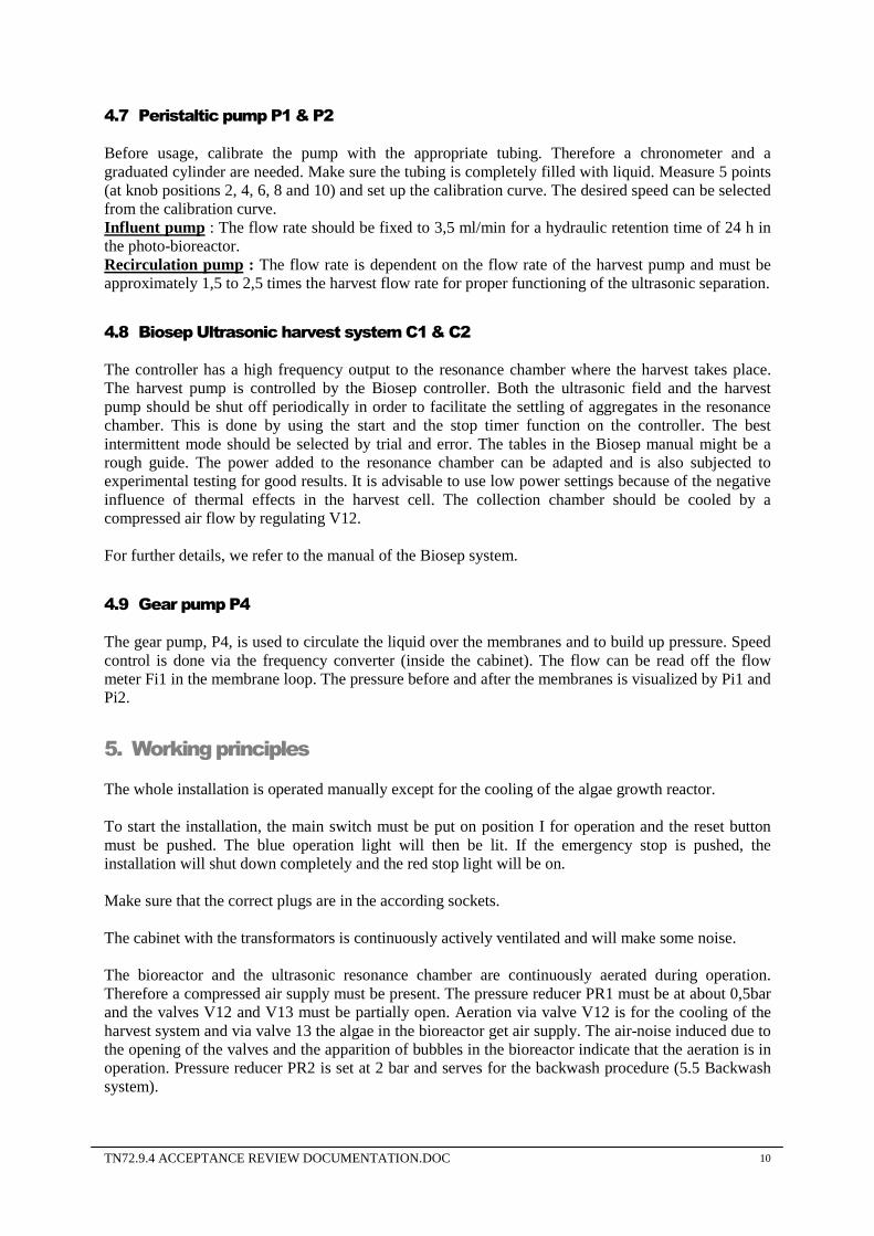
Made by: EPAS Checked by: Project ref: Melissa3 - L2356 Document ref : Issue date: 2004-03-23 Revision date : Component reference K1-K2
Description Cooling bath
Type K15
Sub-type 002-4288
Model Number 1200300581009
Manufacturer Thermo Haake
Sales office Glasatelier Saillart
Function Cooling of the algae bioreactor and the buffertank
Remarks
General Characteristics
Power source Electricity Protection Class (IP) 20 Voltage (V) 230 Dimension (mm) 385 x 465 x 415 Power input (W) 2600 Weight (kg) Power output (W) Design Pressure (bar) Current draw (A) 12 Design Temperature (°C) Fuse protection (A) 2 x 10A; 2 x 5A Safety instructions
Specific Characteristics
Body materials SS
Sealing materials
Connector type
Connector size
Document references Component drawing Certificates Input/output list Guarantee period Electric Wiring Diagram Guarantee documents Warning symbols Manual reference
TN72.9.4 ACCEPTANCE REVIEW DOCUMENTATION.DOC 18
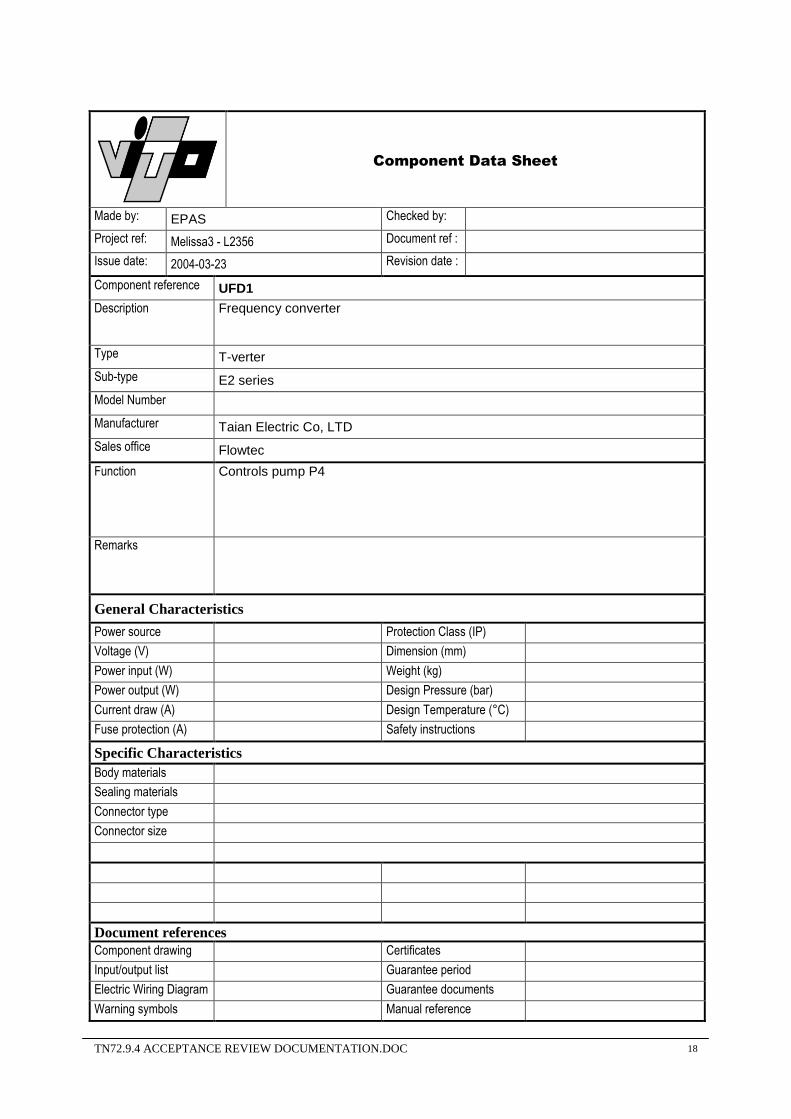
Component Data Sheet
Made by: EPAS Checked by: Project ref: Melissa3 - L2356 Document ref : Issue date: 2004-03-23 Revision date : Component reference UFD1 Description Frequency converter
Type T-verter
Sub-type E2 series
Model Number
Manufacturer Taian Electric Co, LTD
Sales office Flowtec
Function Controls pump P4
Remarks
General Characteristics
Power source Protection Class (IP) Voltage (V) Dimension (mm) Power input (W) Weight (kg) Power output (W) Design Pressure (bar) Current draw (A) Design Temperature (°C) Fuse protection (A) Safety instructions
Specific Characteristics Body materials
Sealing materials
Connector type
Connector size
Document references Component drawing Certificates Input/output list Guarantee period Electric Wiring Diagram Guarantee documents Warning symbols Manual reference
TN72.9.4 ACCEPTANCE REVIEW DOCUMENTATION.DOC 19
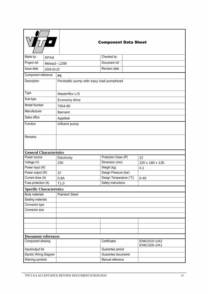
Component Data Sheet
Made by: EPAS Checked by: Project ref: Melissa3 - L2356 Document ref : Issue date: 2004-03-23 Revision date : Component reference P1 Description Peristaltic pump with easy load pumphead
Type Masterflex L/S
Sub-type Economy drive
Model Number 7554-85
Manufacturer Barnant
Sales office Applitek
Function Influent pump
Remarks
General Characteristics Power source Electricity Protection Class (IP) 22 Voltage (V) 230 Dimension (mm) 220 x 180 x 135 Power input (W) Weight (kg) 4,1 Power output (W) 37 Design Pressure (bar) Current draw (A) 0,9A Design Temperature (°C) 0-40 Fuse protection (A) T1,0 Safety instructions
Specific Characteristics Body materials Painted Steel
Sealing materials
Connector type
Connector size
Document references Component drawing
Certificates EN61010-1/A2
EN61326-1/A1 Input/output list Guarantee period Electric Wiring Diagram Guarantee documents Warning symbols Manual reference
TN72.9.4 ACCEPTANCE REVIEW DOCUMENTATION.DOC 20
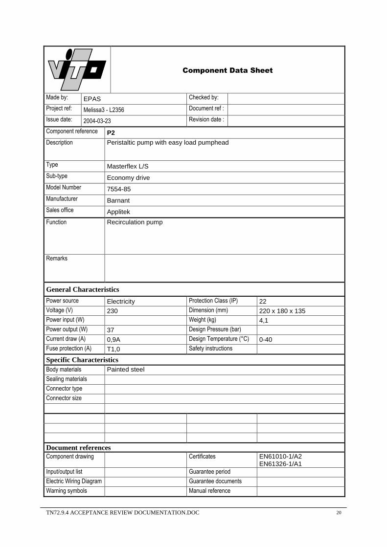
Component Data Sheet
Made by: EPAS Checked by: Project ref: Melissa3 - L2356 Document ref : Issue date: 2004-03-23 Revision date : Component reference P2 Description Peristaltic pump with easy load pumphead
Type Masterflex L/S
Sub-type Economy drive
Model Number 7554-85
Manufacturer Barnant
Sales office Applitek
Function Recirculation pump
Remarks
General Characteristics
Power source Electricity Protection Class (IP) 22 Voltage (V) 230 Dimension (mm) 220 x 180 x 135 Power input (W) Weight (kg) 4,1 Power output (W) 37 Design Pressure (bar) Current draw (A) 0,9A Design Temperature (°C) 0-40 Fuse protection (A) T1,0 Safety instructions
Specific Characteristics Body materials Painted steel
Sealing materials
Connector type
Connector size
Document references Component drawing
Certificates EN61010-1/A2
EN61326-1/A1 Input/output list Guarantee period Electric Wiring Diagram Guarantee documents Warning symbols Manual reference

TN72.9.4 ACCEPTANCE REVIEW DOCUMENTATION.DOC 21
Component Data Sheet
Made by: EPAS Checked by: Project ref: Melissa3 - L2356 Document ref : Issue date: 2004-03-23 Revision date : Component reference P3 Description Gear pump with easy load pumphead
Type Micropump
Sub-type
Model Number 75211-55
Manufacturer Barnant
Sales office Applitek
Function Recirculation pump
Remarks Pumphead : GJ-N21.JF1SA
General Characteristics Power source Electricity Protection Class (IP) 23 Voltage (V) 230 Dimension (mm) 292 x 203 x 184 Power input (W) Weight (kg) 5 Power output (W) 0,075 Design Pressure (bar) Current draw (A) 1,1A Design Temperature (°C) 0-40 Fuse protection (A) T1,6 Safety instructions
Specific Characteristics Body materials ABS case, irridite-coated aluminium chassis
Sealing materials
Connector type
Connector size
Document references Component drawing
Certificates EN61010-1/A2
EN61326-1/A1 Input/output list Guarantee period Electric Wiring Diagram Guarantee documents Warning symbols Manual reference
TN72.9.4 ACCEPTANCE REVIEW DOCUMENTATION.DOC 22
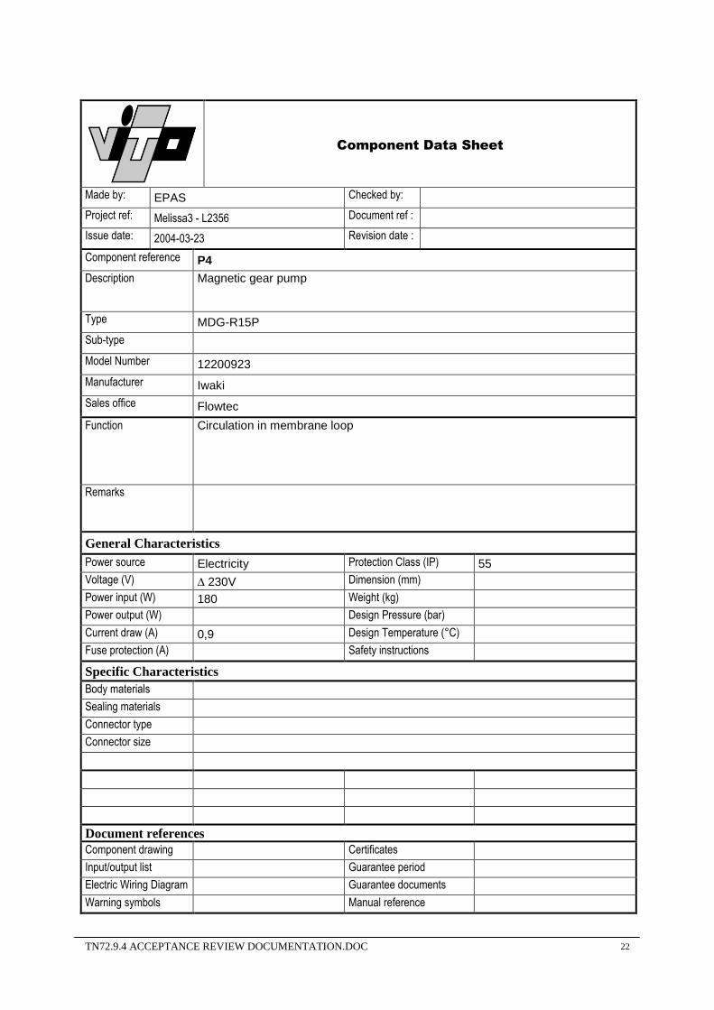
Component Data Sheet
Made by: EPAS Checked by: Project ref: Melissa3 - L2356 Document ref : Issue date: 2004-03-23 Revision date : Component reference P4 Description Magnetic gear pump
Type MDG-R15P
Sub-type
Model Number 12200923
Manufacturer Iwaki
Sales office Flowtec
Function Circulation in membrane loop
Remarks
General Characteristics Power source Electricity Protection Class (IP) 55 Voltage (V) ∆ 230V Dimension (mm) Power input (W) 180 Weight (kg) Power output (W) Design Pressure (bar) Current draw (A) 0,9 Design Temperature (°C) Fuse protection (A) Safety instructions
Specific Characteristics Body materials
Sealing materials
Connector type
Connector size
Document references Component drawing Certificates Input/output list Guarantee period Electric Wiring Diagram Guarantee documents Warning symbols Manual reference

TN72.9.4 ACCEPTANCE REVIEW DOCUMENTATION.DOC 23
Component Data Sheet
Made by: EPAS Checked by: Project ref: Melissa3 - L2356 Document ref : Issue date: 2004-03-23 Revision date : Component reference Ultrasound cell Description Acoustic resonator assembly
Type 50 L
Sub-type 50 L/day
Model Number
Manufacturer Applisens
Sales office Applitek
Function Algae harvest system
Remarks
General Characteristics
Power source electricity Protection Class (IP) Voltage (V) 1 x 230V Dimension (mm) 177 x 97 Power input (W) 10 W Weight (kg) 1,5 Power output (W) Design Pressure (bar) 4 Current draw (A) Design Temperature (°C) 130 Fuse protection (A) Safety instructions
Specific Characteristics Body materials Body: SS316 L, cuvette: pyrex glass
Sealing materials silicone
Connector type ½” tri-clamp, 6 mm and 10 mm barbed fitting
Connector size
Document references Component drawing Certificates Input/output list Guarantee period Electric Wiring Diagram Guarantee documents Warning symbols Manual reference

TN72.9.4 ACCEPTANCE REVIEW DOCUMENTATION.DOC 24
Component Data Sheet
Made by: EPAS Checked by: Project ref: Melissa3 - L2356 Document ref : Issue date: 2004-03-23 Revision date : Component reference Ultrasound controller Description
Type APS 990 Controller
Sub-type
Model Number Z299005020
Manufacturer Applisens
Sales office Applitek
Function Controls the ultrasound resonance cell and the harvest pump
Remarks
General Characteristics
Power source electricity Protection Class (IP) Voltage (V) 1 x 240 Dimension (mm) 130 x 130 x 305 Power input (W) 150 Weight (kg) 3,5 Power output (W) 10 Design Pressure (bar) Current draw (A) Design Temperature (°C) Fuse protection (A) 2 A slow blow 250V Safety instructions
Specific Characteristics
Body materials
Sealing materials
Connector type
Connector size
Document references Component drawing Certificates Input/output list Guarantee period Electric Wiring Diagram Guarantee documents Warning symbols Manual reference

TN72.9.4 ACCEPTANCE REVIEW DOCUMENTATION.DOC 25
Component Data Sheet
Made by: EPAS Checked by: Project ref: Melissa3 – L2356 Document ref : Issue date: 2004-03-23 Revision date : Component reference R1 Description Magnetic stirrer
Type MR3000
Sub-type
Model Number 504-00011-00-1
Manufacturer Heidolph
Sales office Glasatelier Saillart
Function Stirring of the algae bioreactor
Remarks
General Characteristics
Power source Electricity Protection Class (IP) 30 Voltage (V) 230 Dimension (mm) 2400 x 155 x 120 Power input (W) 25 Weight (kg) 2,4 Power output (W) Design Pressure (bar) Current draw (A) Design Temperature (°C) 0-40 Fuse protection (A) Safety instructions
Specific Characteristics
Body materials Polyamide coat housing; active surface: 1.4301; polyester front panel
Sealing materials
Connector type
Connector size
Document references Component drawing Certificates Input/output list Guarantee period Electric Wiring Diagram Guarantee documents Warning symbols Manual reference

TN72.9.4 ACCEPTANCE REVIEW DOCUMENTATION.DOC 26
Component Data Sheet
Made by: EPAS Checked by: Project ref: Melissa3 - L2356 Document ref : Issue date: 2004-03-23 Revision date : Component reference R2 Description Stirrer
Type 80 807 0
Sub-type 80 807 019
Model Number
Manufacturer Crouzet
Sales office Breva
Function Stirring of the buffertank
Remarks
General Characteristics
Power source Electricity Protection Class (IP) Voltage (V) 24 DC Dimension (mm) Power input (W) 17 Weight (kg) 0,800 Power output (W) Design Pressure (bar) Current draw (A) Design Temperature (°C) 40 Fuse protection (A) Safety instructions
Specific Characteristics Body materials
Sealing materials
Connector type
Connector size
Document references Component drawing Certificates Input/output list Guarantee period Electric Wiring Diagram Guarantee documents Warning symbols Manual reference

TN72.9.4 ACCEPTANCE REVIEW DOCUMENTATION.DOC 27
Component Data Sheet
Made by: EPAS Checked by: Project ref: Melissa3 - L2356 Document ref : Issue date: 2004-03-23 Revision date : Component reference R3 Description Stirrer
Type 80 807 0
Sub-type 80 807 019
Model Number
Manufacturer Crouzet
Sales office Breva
Function Stirring of the concentration tank
Remarks
General Characteristics Power source Electricity Protection Class (IP) Voltage (V) 24 DC Dimension (mm) Power input (W) 17 Weight (kg) 0,800 Power output (W) Design Pressure (bar) Current draw (A) Design Temperature (°C) 40 Fuse protection (A) Safety instructions
Specific Characteristics Body materials
Sealing materials
Connector type
Connector size
Document references Component drawing Certificates Input/output list Guarantee period Electric Wiring Diagram Guarantee documents Warning symbols Manual reference
TN72.9.4 ACCEPTANCE REVIEW DOCUMENTATION.DOC
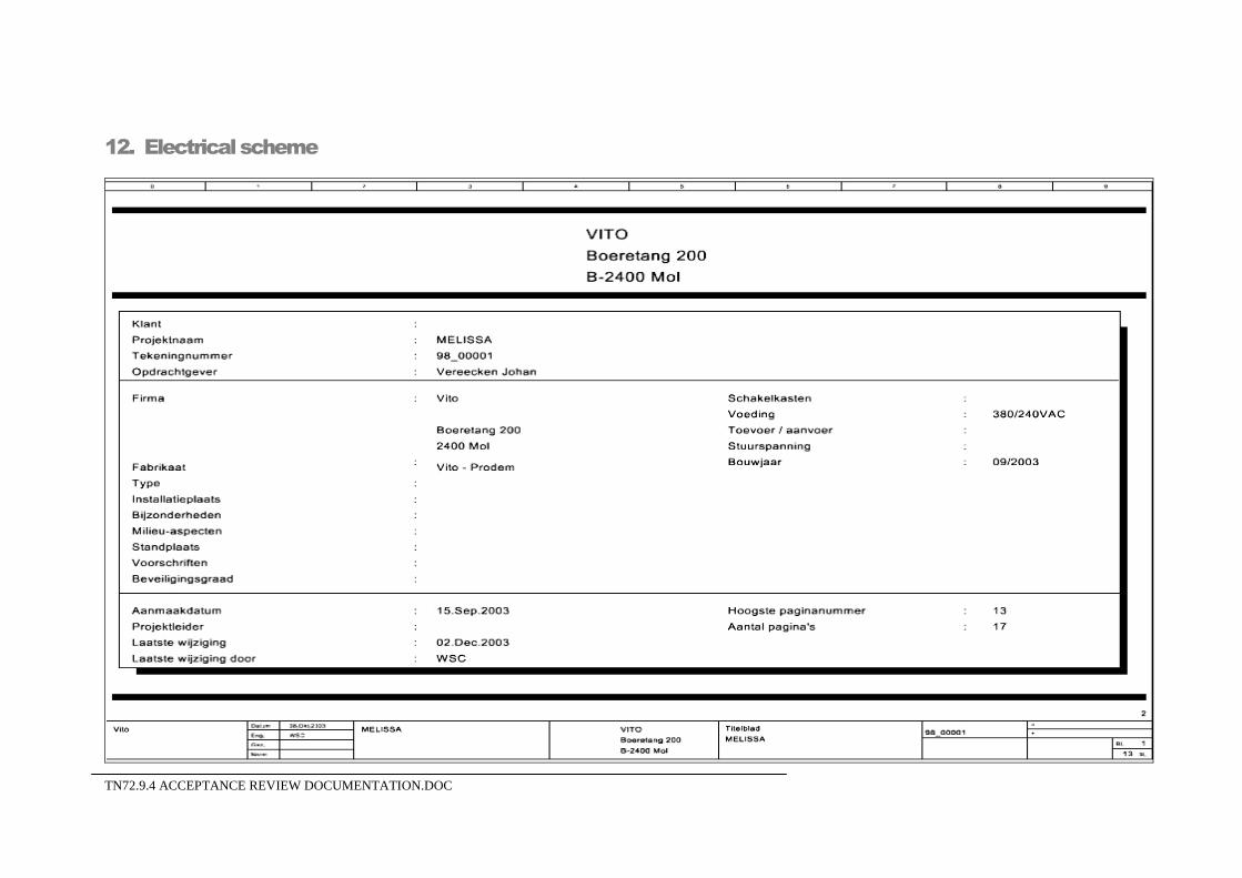
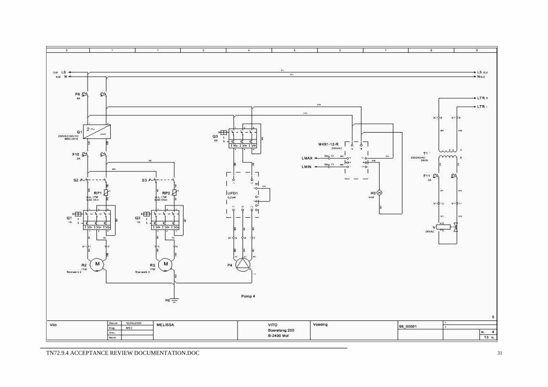
12. Electrical scheme

TN72.9.4 ACCEPTANCE REVIEW DOCUMENTATION.DOC 29

TN72.9.4 ACCEPTANCE REVIEW DOCUMENTATION.DOC 30
TN72.9.4 ACCEPTANCE REVIEW DOCUMENTATION.DOC 31

TN72.9.4 ACCEPTANCE REVIEW DOCUMENTATION.DOC 32

TN72.9.4 ACCEPTANCE REVIEW DOCUMENTATION.DOC 33

TN72.9.4 ACCEPTANCE REVIEW DOCUMENTATION.DOC 34

TN72.9.4 ACCEPTANCE REVIEW DOCUMENTATION.DOC 35

TN72.9.4 ACCEPTANCE REVIEW DOCUMENTATION.DOC 36

TN72.9.4 ACCEPTANCE REVIEW DOCUMENTATION.DOC 37

TN72.9.4 ACCEPTANCE REVIEW DOCUMENTATION.DOC 38

TN72.9.4 ACCEPTANCE REVIEW DOCUMENTATION.DOC 39

TN72.9.4 ACCEPTANCE REVIEW DOCUMENTATION.DOC 40

TN72.9.4 ACCEPTANCE REVIEW DOCUMENTATION.DOC 41

TN72.9.4 ACCEPTANCE REVIEW DOCUMENTATION.DOC 42

TN72.9.4 ACCEPTANCE REVIEW DOCUMENTATION.DOC 43

TN72.9.4 ACCEPTANCE REVIEW DOCUMENTATION.DOC 44