melsec iq-r motion controller programming manual (program
TRANSCRIPT

MELSEC iQ-R Motion ControllerProgramming Manual (Program Design)
-R16MTCPU-R32MTCPU-R64MTCPU


SAFETY PRECAUTIONS(Read these precautions before using this product.)
Before using this product, please read this manual and the relevant manuals carefully and pay full attention to safety to handle
the product correctly.
The precautions given in this manual are concerned with this product only. Refer to MELSEC iQ-R Module Configuration
Manual for a description of the PLC system safety precautions.
In this manual, the safety precautions are classified into two levels: " WARNING" and " CAUTION".
Under some circumstances, failure to observe the precautions given under " CAUTION" may lead to serious
consequences.
Observe the precautions of both levels because they are important for personal and system safety.
Make sure that the end users read this manual and then keep the manual in a safe place for future reference.
[Design Precautions]
WARNING● Configure safety circuits external to the programmable controller to ensure that the entire system
operates safely even when a fault occurs in the external power supply or the programmable controller.
Failure to do so may result in an accident due to an incorrect output or malfunction.
(1) Emergency stop circuits, protection circuits, and protective interlock circuits for conflicting
operations (such as forward/reverse rotations or upper/lower limit positioning) must be configured
external to the programmable controller.
(2) When the programmable controller detects an abnormal condition, it stops the operation and all
outputs are:
• Turned off if the overcurrent or overvoltage protection of the power supply module is activated.
• Held or turned off according to the parameter setting if the self-diagnostic function of the CPU
module detects an error such as a watchdog timer error.
(3) All outputs may be turned on if an error occurs in a part, such as an I/O control part, where the
CPU module cannot detect any error. To ensure safety operation in such a case, provide a safety
mechanism or a fail-safe circuit external to the programmable controller. For a fail-safe circuit
example, refer to "General Safety Requirements" in the MELSEC iQ-R Module Configuration
Manual.
(4) Outputs may remain on or off due to a failure of a component such as a relay and transistor in an
output circuit. Configure an external circuit for monitoring output signals that could cause a
serious accident.
● In an output circuit, when a load current exceeding the rated current or an overcurrent caused by a
load short-circuit flows for a long time, it may cause smoke and fire. To prevent this, configure an
external safety circuit, such as a fuse.
● Configure a circuit so that the programmable controller is turned on first and then the external power
supply. If the external power supply is turned on first, an accident may occur due to an incorrect output
or malfunction.
WARNING Indicates that incorrect handling may cause hazardous conditions, resulting in death or severe injury.
CAUTION Indicates that incorrect handling may cause hazardous conditions, resulting in minor or moderate injury or property damage.
1
2
[Design Precautions]
WARNING● For the operating status of each station after a communication failure, refer to manuals relevant to the
network. Incorrect output or malfunction due to a communication failure may result in an accident.
● When connecting an external device with a CPU module or intelligent function module to modify data
of a running programmable controller, configure an interlock circuit in the program to ensure that the
entire system will always operate safely. For other forms of control (such as program modification,
parameter change, forced output, or operating status change) of a running programmable controller,
read the relevant manuals carefully and ensure that the operation is safe before proceeding. Improper
operation may damage machines or cause accidents.
● Especially, when a remote programmable controller is controlled by an external device, immediate
action cannot be taken if a problem occurs in the programmable controller due to a communication
failure. To prevent this, configure an interlock circuit in the program, and determine corrective actions
to be taken between the external device and CPU module in case of a communication failure.
● Do not write any data to the "system area" and "write-protect area" of the buffer memory in the
module. Also, do not use any "use prohibited" signals as an output signal from the CPU module to
each module. Doing so may cause malfunction of the programmable controller system. For the
"system area", "write-protect area", and the "use prohibited" signals, refer to the user's manual for the
module used.
● If a communication cable is disconnected, the network may be unstable, resulting in a communication
failure of multiple stations. Configure an interlock circuit in the program to ensure that the entire
system will always operate safely even if communications fail. Failure to do so may result in an
accident due to an incorrect output or malfunction.
● To maintain the safety of the programmable controller system against unauthorized access from
external devices via the network, take appropriate measures. To maintain the safety against
unauthorized access via the Internet, take measures such as installing a firewall.
● Configure safety circuits external to the programmable controller to ensure that the entire system
operates safely even when a fault occurs in the external power supply or the programmable controller.
Failure to do so may result in an accident due to an incorrect output or malfunction.
● If safety standards (ex., robot safety rules, etc.,) apply to the system using the module, servo amplifier
and servo motor, make sure that the safety standards are satisfied.
● Construct a safety circuit externally of the module or servo amplifier if the abnormal operation of the
module or servo amplifier differs from the safety directive operation in the system.
● Do not remove the SSCNET cable while turning on the control circuit power supply of modules and
servo amplifier. Do not see directly the light generated from SSCNET connector of the module or
servo amplifier and the end of SSCNET cable. When the light gets into eyes, you may feel
something wrong with eyes. (The light source of SSCNET complies with class 1 defined in
JISC6802 or IEC60825-1.)

[Design Precautions]
[Installation Precautions]
CAUTION● Do not install the control lines or communication cables together with the main circuit lines or power
cables. Keep a distance of 100mm or more between them. Failure to do so may result in malfunction
due to noise.
● During control of an inductive load such as a lamp, heater, or solenoid valve, a large current
(approximately ten times greater than normal) may flow when the output is turned from off to on.
Therefore, use a module that has a sufficient current rating.
● After the CPU module is powered on or is reset, the time taken to enter the RUN status varies
depending on the system configuration, parameter settings, and/or program size. Design circuits so
that the entire system will always operate safely, regardless of the time.
● Do not power off the programmable controller or reset the CPU module while the settings are being
written. Doing so will make the data in the flash ROM and SD memory card undefined. The values
need to be set in the buffer memory and written to the flash ROM and SD memory card again. Doing
so also may cause malfunction or failure of the module.
● When changing the operating status of the CPU module from external devices (such as the remote
RUN/STOP functions), select "Do Not Open by Program" for "Opening Method" of "Module
Parameter". If "Open by Program" is selected, an execution of the remote STOP function causes the
communication line to close. Consequently, the CPU module cannot reopen the line, and external
devices cannot execute the remote RUN function.
WARNING● Shut off the external power supply (all phases) used in the system before mounting or removing the
module. Failure to do so may result in electric shock or cause the module to fail or malfunction.
3

4
[Installation Precautions]
[Wiring Precautions]
CAUTION● Use the programmable controller in an environment that meets the general specifications in the Safety
Guidelines included with the base unit. Failure to do so may result in electric shock, fire, malfunction,
or damage to or deterioration of the product.
● To mount a module, place the concave part(s) located at the bottom onto the guide(s) of the base unit,
and push in the module until the hook(s) located at the top snaps into place. Incorrect interconnection
may cause malfunction, failure, or drop of the module.
● To mount a module with no module fixing hook, place the concave part(s) located at the bottom onto
the guide(s) of the base unit, push in the module, and fix it with screw(s). Incorrect interconnection
may cause malfunction, failure, or drop of the module.
● When using the programmable controller in an environment of frequent vibrations, fix the module with
a screw.
● Tighten the screws within the specified torque range. Undertightening can cause drop of the screw,
short circuit, or malfunction. Overtightening can damage the screw and/or module, resulting in drop,
short circuit, or malfunction.
● When using an extension cable, connect it to the extension cable connector of the base unit securely.
Check the connection for looseness. Poor contact may cause malfunction.
● When using an SD memory card, fully insert it into the SD memory card slot. Check that it is inserted
completely. Poor contact may cause malfunction.
● Securely insert an extended SRAM cassette or a battery-less option cassette into the cassette
connector of the CPU module. After insertion, close the cassette cover and check that the cassette is
inserted completely. Poor contact may cause malfunction.
● Do not directly touch any conductive parts and electronic components of the module, SD memory
card, extended SRAM cassette, battery-less option cassette, or connector. Doing so can cause
malfunction or failure of the module.
WARNING● Shut off the external power supply (all phases) used in the system before installation and wiring.
Failure to do so may result in electric shock or cause the module to fail or malfunction.
● After installation and wiring, attach a blank cover module (RG60) to each empty slot and an included
extension connector protective cover to the unused extension cable connector before powering on the
system for operation. Failure to do so may result in electric shock.

[Wiring Precautions]
CAUTION● Individually ground the FG and LG terminals of the programmable controller with a ground resistance
of 100 ohms or less. Failure to do so may result in electric shock or malfunction.
● Use applicable solderless terminals and tighten them within the specified torque range. If any spade
solderless terminal is used, it may be disconnected when the terminal screw comes loose, resulting in
failure.
● Check the rated voltage and signal layout before wiring to the module, and connect the cables
correctly. Connecting a power supply with a different voltage rating or incorrect wiring may cause fire
or failure.
● Connectors for external devices must be crimped or pressed with the tool specified by the
manufacturer, or must be correctly soldered. Incomplete connections may cause short circuit, fire, or
malfunction.
● Securely connect the connector to the module. Poor contact may cause malfunction.
● Do not install the control lines or communication cables together with the main circuit lines or power
cables. Keep a distance of 100mm or more between them. Failure to do so may result in malfunction
due to noise.
● Place the cables in a duct or clamp them. If not, dangling cable may swing or inadvertently be pulled,
resulting in damage to the module or cables or malfunction due to poor contact. Do not clamp the
extension cables with the jacket stripped. Doing so may change the characteristics of the cables,
resulting in malfunction.
● Check the interface type and correctly connect the cable. Incorrect wiring (connecting the cable to an
incorrect interface) may cause failure of the module and external device.
● Tighten the terminal screws or connector screws within the specified torque range. Undertightening
can cause drop of the screw, short circuit, fire, or malfunction. Overtightening can damage the screw
and/or module, resulting in drop, short circuit, fire, or malfunction.
● When disconnecting the cable from the module, do not pull the cable by the cable part. For the cable
with connector, hold the connector part of the cable. For the cable connected to the terminal block,
loosen the terminal screw. Pulling the cable connected to the module may result in malfunction or
damage to the module or cable.
● Prevent foreign matter such as dust or wire chips from entering the module. Such foreign matter can
cause a fire, failure, or malfunction.
● A protective film is attached to the top of the module to prevent foreign matter, such as wire chips,
from entering the module during wiring. Do not remove the film during wiring. Remove it for heat
dissipation before system operation.
● Programmable controllers must be installed in control panels. Connect the main power supply to the
power supply module in the control panel through a relay terminal block. Wiring and replacement of a
power supply module must be performed by qualified maintenance personnel with knowledge of
protection against electric shock. For wiring, refer to the MELSEC iQ-R Module Configuration Manual.
● For Ethernet cables to be used in the system, select the ones that meet the specifications in the user's
manual for the module used. If not, normal data transmission is not guaranteed.
5

6
[Startup and Maintenance Precautions]
[Startup and Maintenance Precautions]
WARNING● Do not touch any terminal while power is on. Doing so will cause electric shock or malfunction.
● Correctly connect the battery connector. Do not charge, disassemble, heat, short-circuit, solder, or
throw the battery into the fire. Also, do not expose it to liquid or strong shock. Doing so will cause the
battery to produce heat, explode, ignite, or leak, resulting in injury and fire.
● Shut off the external power supply (all phases) used in the system before cleaning the module or
retightening the terminal screws, connector screws, or module fixing screws. Failure to do so may
result in electric shock.
CAUTION● When connecting an external device with a CPU module or intelligent function module to modify data
of a running programmable controller, configure an interlock circuit in the program to ensure that the
entire system will always operate safely. For other forms of control (such as program modification,
parameter change, forced output, or operating status change) of a running programmable controller,
read the relevant manuals carefully and ensure that the operation is safe before proceeding. Improper
operation may damage machines or cause accidents.
● Especially, when a remote programmable controller is controlled by an external device, immediate
action cannot be taken if a problem occurs in the programmable controller due to a communication
failure. To prevent this, configure an interlock circuit in the program, and determine corrective actions
to be taken between the external device and CPU module in case of a communication failure.
● Do not disassemble or modify the modules. Doing so may cause failure, malfunction, injury, or a fire.
● Use any radio communication device such as a cellular phone or PHS (Personal Handy-phone
System) more than 25cm away in all directions from the programmable controller. Failure to do so
may cause malfunction.
● Shut off the external power supply (all phases) used in the system before mounting or removing the
module. Failure to do so may cause the module to fail or malfunction.
● Tighten the screws within the specified torque range. Undertightening can cause drop of the
component or wire, short circuit, or malfunction. Overtightening can damage the screw and/or module,
resulting in drop, short circuit, or malfunction.
● After the first use of the product, do not perform each of the following operations more than 50 times
(IEC 61131-2/JIS B 3502 compliant).
Exceeding the limit may cause malfunction.
• Mounting/removing the module to/from the base unit
• Inserting/removing the extended SRAM cassette or battery-less option cassette to/from the
CPU module
• Mounting/removing the terminal block to/from the module
● After the first use of the product, do not insert/remove the SD memory card to/from the CPU module
more than 500 times. Exceeding the limit may cause malfunction.
● Do not touch the metal terminals on the back side of the SD memory card. Doing so may cause
malfunction or failure of the module.
● Do not touch the integrated circuits on the circuit board of an extended SRAM cassette or a battery-
less option cassette. Doing so may cause malfunction or failure of the module.

[Startup and Maintenance Precautions]
[Operating Precautions]
CAUTION● Do not drop or apply shock to the battery to be installed in the module. Doing so may damage the
battery, causing the battery fluid to leak inside the battery. If the battery is dropped or any shock is
applied to it, dispose of it without using.
● Startup and maintenance of a control panel must be performed by qualified maintenance personnel
with knowledge of protection against electric shock. Lock the control panel so that only qualified
maintenance personnel can operate it.
● Before handling the module, touch a conducting object such as a grounded metal to discharge the
static electricity from the human body. Failure to do so may cause the module to fail or malfunction.
● Before testing the operation, set a low speed value for the speed limit parameter so that the operation
can be stopped immediately upon occurrence of a hazardous condition.
● Confirm and adjust the program and each parameter before operation. Unpredictable movements
may occur depending on the machine.
● When using the absolute position system function, on starting up, and when the module or absolute
position motor has been replaced, always perform a home position return.
● Before starting the operation, confirm the brake function.
● Do not perform a megger test (insulation resistance measurement) during inspection.
● After maintenance and inspections are completed, confirm that the position detection of the absolute
position detection function is correct.
● Lock the control panel and prevent access to those who are not certified to handle or install electric
equipment.
CAUTION● When changing data and operating status, and modifying program of the running programmable
controller from an external device such as a personal computer connected to an intelligent function
module, read relevant manuals carefully and ensure the safety before operation. Incorrect change or
modification may cause system malfunction, damage to the machines, or accidents.
● Do not power off the programmable controller or reset the CPU module while the setting values in the
buffer memory are being written to the flash ROM in the module. Doing so will make the data in the
flash ROM and SD memory card undefined. The values need to be set in the buffer memory and
written to the flash ROM and SD memory card again. Doing so also may cause malfunction or failure
of the module.
● Note that when the reference axis speed is specified for interpolation operation, the speed of the
partner axis (2nd, 3rd, or 4th axis) may exceed the speed limit value.
● Do not go near the machine during test operations or during operations such as teaching. Doing so
may lead to injuries.
7

8
[Disposal Precautions]
[Transportation Precautions]
CAUTION● When disposing of this product, treat it as industrial waste.
● When disposing of batteries, separate them from other wastes according to the local regulations. For
details on battery regulations in EU member states, refer to the MELSEC iQ-R Module Configuration
Manual.
CAUTION● When transporting lithium batteries, follow the transportation regulations. For details on the regulated
models, refer to the MELSEC iQ-R Module Configuration Manual.
● The halogens (such as fluorine, chlorine, bromine, and iodine), which are contained in a fumigant
used for disinfection and pest control of wood packaging materials, may cause failure of the product.
Prevent the entry of fumigant residues into the product or consider other methods (such as heat
treatment) instead of fumigation. The disinfection and pest control measures must be applied to
unprocessed raw wood.

CONDITIONS OF USE FOR THE PRODUCT
INTRODUCTIONThank you for purchasing the Mitsubishi Electric MELSEC iQ-R series programmable controllers.
This manual describes the commands and programs for the programming of the relevant products listed below.
Before using this product, please read this manual and the relevant manuals carefully and develop familiarity with the
functions and performance of the MELSEC iQ-R series programmable controller to handle the product correctly.
When applying the program examples provided in this manual to an actual system, ensure the applicability and confirm that it
will not cause system control problems.
Please make sure that the end users read this manual.
Relevant productsR16MTCPU, R32MTCPU, R64MTCPU
(1) Mitsubishi programmable controller ("the PRODUCT") shall be used in conditions;i) where any problem, fault or failure occurring in the PRODUCT, if any, shall not lead to any major or serious accident; and ii) where the backup and fail-safe function are systematically or automatically provided outside of the PRODUCT for the case of any problem, fault or failure occurring in the PRODUCT.
(2) The PRODUCT has been designed and manufactured for the purpose of being used in general industries.MITSUBISHI SHALL HAVE NO RESPONSIBILITY OR LIABILITY (INCLUDING, BUT NOT LIMITED TO ANY AND ALL RESPONSIBILITY OR LIABILITY BASED ON CONTRACT, WARRANTY, TORT, PRODUCT LIABILITY) FOR ANY INJURY OR DEATH TO PERSONS OR LOSS OR DAMAGE TO PROPERTY CAUSED BY the PRODUCT THAT ARE OPERATED OR USED IN APPLICATION NOT INTENDED OR EXCLUDED BY INSTRUCTIONS, PRECAUTIONS, OR WARNING CONTAINED IN MITSUBISHI'S USER, INSTRUCTION AND/OR SAFETY MANUALS, TECHNICAL BULLETINS AND GUIDELINES FOR the PRODUCT. ("Prohibited Application")Prohibited Applications include, but not limited to, the use of the PRODUCT in;• Nuclear Power Plants and any other power plants operated by Power companies, and/or any other cases in which the
public could be affected if any problem or fault occurs in the PRODUCT.• Railway companies or Public service purposes, and/or any other cases in which establishment of a special quality
assurance system is required by the Purchaser or End User.• Aircraft or Aerospace, Medical applications, Train equipment, transport equipment such as Elevator and Escalator,
Incineration and Fuel devices, Vehicles, Manned transportation, Equipment for Recreation and Amusement, and Safety devices, handling of Nuclear or Hazardous Materials or Chemicals, Mining and Drilling, and/or other applications where there is a significant risk of injury to the public or property.
Notwithstanding the above restrictions, Mitsubishi may in its sole discretion, authorize use of the PRODUCT in one or more of the Prohibited Applications, provided that the usage of the PRODUCT is limited only for the specific applications agreed to by Mitsubishi and provided further that no special quality assurance or fail-safe, redundant or other safety features which exceed the general specifications of the PRODUCTs are required. For details, please contact the Mitsubishi representative in your region.
9

10
CONTENTSSAFETY PRECAUTIONS . . . . . . . . . . . . . . . . . . . . . . . . . . . . . . . . . . . . . . . . . . . . . . . . . . . . . . . . . . . . . . . . . . . .1
CONDITIONS OF USE FOR THE PRODUCT . . . . . . . . . . . . . . . . . . . . . . . . . . . . . . . . . . . . . . . . . . . . . . . . . . . .9
INTRODUCTION. . . . . . . . . . . . . . . . . . . . . . . . . . . . . . . . . . . . . . . . . . . . . . . . . . . . . . . . . . . . . . . . . . . . . . . . . . .9
RELEVANT MANUALS . . . . . . . . . . . . . . . . . . . . . . . . . . . . . . . . . . . . . . . . . . . . . . . . . . . . . . . . . . . . . . . . . . . . .15
TERMS . . . . . . . . . . . . . . . . . . . . . . . . . . . . . . . . . . . . . . . . . . . . . . . . . . . . . . . . . . . . . . . . . . . . . . . . . . . . . . . . .16
MANUAL PAGE ORGANIZATION. . . . . . . . . . . . . . . . . . . . . . . . . . . . . . . . . . . . . . . . . . . . . . . . . . . . . . . . . . . . .17
CHAPTER 1 OVERVIEW 20
1.1 Performance Specifications . . . . . . . . . . . . . . . . . . . . . . . . . . . . . . . . . . . . . . . . . . . . . . . . . . . . . . . . . . . . . . . 20
Motion SFC performance specifications . . . . . . . . . . . . . . . . . . . . . . . . . . . . . . . . . . . . . . . . . . . . . . . . . . . . . . . 20
Operation control/transition control specifications . . . . . . . . . . . . . . . . . . . . . . . . . . . . . . . . . . . . . . . . . . . . . . . . 21
1.2 Structure of the Motion CPU Program. . . . . . . . . . . . . . . . . . . . . . . . . . . . . . . . . . . . . . . . . . . . . . . . . . . . . . . 29
CHAPTER 2 MOTION DEDICATED PLC INSTRUCTION 30
2.1 Outline of Motion Dedicated PLC Instruction . . . . . . . . . . . . . . . . . . . . . . . . . . . . . . . . . . . . . . . . . . . . . . . . . 30
2.2 Motion Dedicated PLC Instruction. . . . . . . . . . . . . . . . . . . . . . . . . . . . . . . . . . . . . . . . . . . . . . . . . . . . . . . . . . 31
Motion SFC start request from the PLC CPU to the Motion CPU: M(P).SFCS/D(P).SFCS . . . . . . . . . . . . . . . . 32
Servo program start request from the PLC CPU to the Motion CPU: M(P).SVST/D(P).SVST . . . . . . . . . . . . . . 35
Direct positioning start instruction from the PLC CPU to the Motion CPU: M(P).SVSTD/D(P).SVSTD . . . . . . . 41
Current value change instruction from the PLC CPU to the Motion CPU: M(P).CHGA/D(P).CHGA. . . . . . . . . . 54
Current value change instruction of command generation axis from the PLC CPU to the Motion CPU:
M(P).CHGAS/D(P).CHGAS. . . . . . . . . . . . . . . . . . . . . . . . . . . . . . . . . . . . . . . . . . . . . . . . . . . . . . . . . . . . . . . . . 58
Speed change instruction from the PLC CPU to the Motion CPU: M(P).CHGV/D(P).CHGV . . . . . . . . . . . . . . . 62
Speed change instruction of command generation axis from the PLC CPU to the Motion CPU: M(P).CHGVS/
D(P).CHGVS . . . . . . . . . . . . . . . . . . . . . . . . . . . . . . . . . . . . . . . . . . . . . . . . . . . . . . . . . . . . . . . . . . . . . . . . . . . . 67
Torque limit value change request instruction from the PLC CPU to the Motion CPU: M(P).CHGT/D(P).CHGT 72
Machine program operation start request from the PLC CPU to the Motion CPU: M(P).MCNST/D(P).MCNST. 76
Write bit device to the Motion CPU: M(P).BITWR/D(P).BITWR . . . . . . . . . . . . . . . . . . . . . . . . . . . . . . . . . . . . . 80
Interrupt instruction to the other CPU: M(P).GINT/D(P).GINT. . . . . . . . . . . . . . . . . . . . . . . . . . . . . . . . . . . . . . . 84
2.3 Precautions . . . . . . . . . . . . . . . . . . . . . . . . . . . . . . . . . . . . . . . . . . . . . . . . . . . . . . . . . . . . . . . . . . . . . . . . . . . . 87
CPU buffer memory address used in Motion dedicated instruction. . . . . . . . . . . . . . . . . . . . . . . . . . . . . . . . . . . 87
Number of blocks used for Motion dedicated PLC instruction. . . . . . . . . . . . . . . . . . . . . . . . . . . . . . . . . . . . . . . 89
Execution of Motion dedicated PLC instruction . . . . . . . . . . . . . . . . . . . . . . . . . . . . . . . . . . . . . . . . . . . . . . . . . . 93
Complete status information . . . . . . . . . . . . . . . . . . . . . . . . . . . . . . . . . . . . . . . . . . . . . . . . . . . . . . . . . . . . . . . . 94
Order of instruction execution . . . . . . . . . . . . . . . . . . . . . . . . . . . . . . . . . . . . . . . . . . . . . . . . . . . . . . . . . . . . . . . 95
CHAPTER 3 MOTION SFC PROGRAMS 97
3.1 Motion SFC Program Configuration . . . . . . . . . . . . . . . . . . . . . . . . . . . . . . . . . . . . . . . . . . . . . . . . . . . . . . . . 97
3.2 Motion SFC Chart Symbol List. . . . . . . . . . . . . . . . . . . . . . . . . . . . . . . . . . . . . . . . . . . . . . . . . . . . . . . . . . . . . 98
3.3 Branch and Coupling Chart List . . . . . . . . . . . . . . . . . . . . . . . . . . . . . . . . . . . . . . . . . . . . . . . . . . . . . . . . . . 100
3.4 Motion SFC Program Name . . . . . . . . . . . . . . . . . . . . . . . . . . . . . . . . . . . . . . . . . . . . . . . . . . . . . . . . . . . . . . 103
3.5 Steps. . . . . . . . . . . . . . . . . . . . . . . . . . . . . . . . . . . . . . . . . . . . . . . . . . . . . . . . . . . . . . . . . . . . . . . . . . . . . . . . . 104
Motion control step . . . . . . . . . . . . . . . . . . . . . . . . . . . . . . . . . . . . . . . . . . . . . . . . . . . . . . . . . . . . . . . . . . . . . . 104
Operation control step . . . . . . . . . . . . . . . . . . . . . . . . . . . . . . . . . . . . . . . . . . . . . . . . . . . . . . . . . . . . . . . . . . . . 105
Subroutine call/start step . . . . . . . . . . . . . . . . . . . . . . . . . . . . . . . . . . . . . . . . . . . . . . . . . . . . . . . . . . . . . . . . . . 106
Clear step . . . . . . . . . . . . . . . . . . . . . . . . . . . . . . . . . . . . . . . . . . . . . . . . . . . . . . . . . . . . . . . . . . . . . . . . . . . . . 107
3.6 Transitions . . . . . . . . . . . . . . . . . . . . . . . . . . . . . . . . . . . . . . . . . . . . . . . . . . . . . . . . . . . . . . . . . . . . . . . . . . . . 108
3.7 Jump, Pointer. . . . . . . . . . . . . . . . . . . . . . . . . . . . . . . . . . . . . . . . . . . . . . . . . . . . . . . . . . . . . . . . . . . . . . . . . . 110

CO
NT
EN
TS
3.8 END. . . . . . . . . . . . . . . . . . . . . . . . . . . . . . . . . . . . . . . . . . . . . . . . . . . . . . . . . . . . . . . . . . . . . . . . . . . . . . . . . . 111
3.9 Branches, Couplings. . . . . . . . . . . . . . . . . . . . . . . . . . . . . . . . . . . . . . . . . . . . . . . . . . . . . . . . . . . . . . . . . . . . 112
Series transition. . . . . . . . . . . . . . . . . . . . . . . . . . . . . . . . . . . . . . . . . . . . . . . . . . . . . . . . . . . . . . . . . . . . . . . . . 112
Selective branch, selective coupling . . . . . . . . . . . . . . . . . . . . . . . . . . . . . . . . . . . . . . . . . . . . . . . . . . . . . . . . . 113
Parallel branch, parallel coupling. . . . . . . . . . . . . . . . . . . . . . . . . . . . . . . . . . . . . . . . . . . . . . . . . . . . . . . . . . . . 114
3.10 Y/N Transitions . . . . . . . . . . . . . . . . . . . . . . . . . . . . . . . . . . . . . . . . . . . . . . . . . . . . . . . . . . . . . . . . . . . . . . . . 116
3.11 Motion SFC Comments . . . . . . . . . . . . . . . . . . . . . . . . . . . . . . . . . . . . . . . . . . . . . . . . . . . . . . . . . . . . . . . . . . 120
CHAPTER 4 OPERATION CONTROL PROGRAMS 122
4.1 Operation Control Programs . . . . . . . . . . . . . . . . . . . . . . . . . . . . . . . . . . . . . . . . . . . . . . . . . . . . . . . . . . . . . 122
4.2 Device Descriptions . . . . . . . . . . . . . . . . . . . . . . . . . . . . . . . . . . . . . . . . . . . . . . . . . . . . . . . . . . . . . . . . . . . . 127
4.3 Constant Descriptions . . . . . . . . . . . . . . . . . . . . . . . . . . . . . . . . . . . . . . . . . . . . . . . . . . . . . . . . . . . . . . . . . . 129
4.4 Labels . . . . . . . . . . . . . . . . . . . . . . . . . . . . . . . . . . . . . . . . . . . . . . . . . . . . . . . . . . . . . . . . . . . . . . . . . . . . . . . . 130
Types. . . . . . . . . . . . . . . . . . . . . . . . . . . . . . . . . . . . . . . . . . . . . . . . . . . . . . . . . . . . . . . . . . . . . . . . . . . . . . . . . 130
Data types . . . . . . . . . . . . . . . . . . . . . . . . . . . . . . . . . . . . . . . . . . . . . . . . . . . . . . . . . . . . . . . . . . . . . . . . . . . . . 130
Arrays . . . . . . . . . . . . . . . . . . . . . . . . . . . . . . . . . . . . . . . . . . . . . . . . . . . . . . . . . . . . . . . . . . . . . . . . . . . . . . . . 131
Structures . . . . . . . . . . . . . . . . . . . . . . . . . . . . . . . . . . . . . . . . . . . . . . . . . . . . . . . . . . . . . . . . . . . . . . . . . . . . . 132
Precautions . . . . . . . . . . . . . . . . . . . . . . . . . . . . . . . . . . . . . . . . . . . . . . . . . . . . . . . . . . . . . . . . . . . . . . . . . . . . 134
4.5 Binary Operations . . . . . . . . . . . . . . . . . . . . . . . . . . . . . . . . . . . . . . . . . . . . . . . . . . . . . . . . . . . . . . . . . . . . . . 135
Substitution: = . . . . . . . . . . . . . . . . . . . . . . . . . . . . . . . . . . . . . . . . . . . . . . . . . . . . . . . . . . . . . . . . . . . . . . . . . . 135
Addition: + . . . . . . . . . . . . . . . . . . . . . . . . . . . . . . . . . . . . . . . . . . . . . . . . . . . . . . . . . . . . . . . . . . . . . . . . . . . . . 137
Subtraction: - . . . . . . . . . . . . . . . . . . . . . . . . . . . . . . . . . . . . . . . . . . . . . . . . . . . . . . . . . . . . . . . . . . . . . . . . . . . 138
Multiplication: * . . . . . . . . . . . . . . . . . . . . . . . . . . . . . . . . . . . . . . . . . . . . . . . . . . . . . . . . . . . . . . . . . . . . . . . . . 139
Division: / . . . . . . . . . . . . . . . . . . . . . . . . . . . . . . . . . . . . . . . . . . . . . . . . . . . . . . . . . . . . . . . . . . . . . . . . . . . . . . 140
Remainder: % . . . . . . . . . . . . . . . . . . . . . . . . . . . . . . . . . . . . . . . . . . . . . . . . . . . . . . . . . . . . . . . . . . . . . . . . . . 141
4.6 Bit Operations . . . . . . . . . . . . . . . . . . . . . . . . . . . . . . . . . . . . . . . . . . . . . . . . . . . . . . . . . . . . . . . . . . . . . . . . . 142
Bit inversion (Complement): ~ . . . . . . . . . . . . . . . . . . . . . . . . . . . . . . . . . . . . . . . . . . . . . . . . . . . . . . . . . . . . . . 142
Bit logical AND: & . . . . . . . . . . . . . . . . . . . . . . . . . . . . . . . . . . . . . . . . . . . . . . . . . . . . . . . . . . . . . . . . . . . . . . . 143
Bit logical OR: | . . . . . . . . . . . . . . . . . . . . . . . . . . . . . . . . . . . . . . . . . . . . . . . . . . . . . . . . . . . . . . . . . . . . . . . . . 144
Bit exclusive logical OR: ^ . . . . . . . . . . . . . . . . . . . . . . . . . . . . . . . . . . . . . . . . . . . . . . . . . . . . . . . . . . . . . . . . . 145
Bit right shift: >>. . . . . . . . . . . . . . . . . . . . . . . . . . . . . . . . . . . . . . . . . . . . . . . . . . . . . . . . . . . . . . . . . . . . . . . . . 146
Bit left shift: <<. . . . . . . . . . . . . . . . . . . . . . . . . . . . . . . . . . . . . . . . . . . . . . . . . . . . . . . . . . . . . . . . . . . . . . . . . . 147
Sign inversion (Complement of 2): - . . . . . . . . . . . . . . . . . . . . . . . . . . . . . . . . . . . . . . . . . . . . . . . . . . . . . . . . . 148
4.7 Standard Functions. . . . . . . . . . . . . . . . . . . . . . . . . . . . . . . . . . . . . . . . . . . . . . . . . . . . . . . . . . . . . . . . . . . . . 149
Sine: SIN . . . . . . . . . . . . . . . . . . . . . . . . . . . . . . . . . . . . . . . . . . . . . . . . . . . . . . . . . . . . . . . . . . . . . . . . . . . . . . 149
Cosine: COS . . . . . . . . . . . . . . . . . . . . . . . . . . . . . . . . . . . . . . . . . . . . . . . . . . . . . . . . . . . . . . . . . . . . . . . . . . . 150
Tangent: TAN. . . . . . . . . . . . . . . . . . . . . . . . . . . . . . . . . . . . . . . . . . . . . . . . . . . . . . . . . . . . . . . . . . . . . . . . . . . 151
Arcsine: ASIN . . . . . . . . . . . . . . . . . . . . . . . . . . . . . . . . . . . . . . . . . . . . . . . . . . . . . . . . . . . . . . . . . . . . . . . . . . 152
Arccosine: ACOS. . . . . . . . . . . . . . . . . . . . . . . . . . . . . . . . . . . . . . . . . . . . . . . . . . . . . . . . . . . . . . . . . . . . . . . . 153
Arctangent: ATAN . . . . . . . . . . . . . . . . . . . . . . . . . . . . . . . . . . . . . . . . . . . . . . . . . . . . . . . . . . . . . . . . . . . . . . . 154
Square root: SQRT . . . . . . . . . . . . . . . . . . . . . . . . . . . . . . . . . . . . . . . . . . . . . . . . . . . . . . . . . . . . . . . . . . . . . . 155
Natural logarithm: LN. . . . . . . . . . . . . . . . . . . . . . . . . . . . . . . . . . . . . . . . . . . . . . . . . . . . . . . . . . . . . . . . . . . . . 156
Exponential operation: EXP. . . . . . . . . . . . . . . . . . . . . . . . . . . . . . . . . . . . . . . . . . . . . . . . . . . . . . . . . . . . . . . . 157
Absolute value: ABS . . . . . . . . . . . . . . . . . . . . . . . . . . . . . . . . . . . . . . . . . . . . . . . . . . . . . . . . . . . . . . . . . . . . . 158
Round-off: RND . . . . . . . . . . . . . . . . . . . . . . . . . . . . . . . . . . . . . . . . . . . . . . . . . . . . . . . . . . . . . . . . . . . . . . . . . 159
Round-down: FIX. . . . . . . . . . . . . . . . . . . . . . . . . . . . . . . . . . . . . . . . . . . . . . . . . . . . . . . . . . . . . . . . . . . . . . . . 160
Round-up: FUP . . . . . . . . . . . . . . . . . . . . . . . . . . . . . . . . . . . . . . . . . . . . . . . . . . . . . . . . . . . . . . . . . . . . . . . . . 161
BCD -> BIN conversion: BIN . . . . . . . . . . . . . . . . . . . . . . . . . . . . . . . . . . . . . . . . . . . . . . . . . . . . . . . . . . . . . . . 162
BIN -> BCD conversion: BCD . . . . . . . . . . . . . . . . . . . . . . . . . . . . . . . . . . . . . . . . . . . . . . . . . . . . . . . . . . . . . . 163
4.8 Data Control . . . . . . . . . . . . . . . . . . . . . . . . . . . . . . . . . . . . . . . . . . . . . . . . . . . . . . . . . . . . . . . . . . . . . . . . . . . 164
11

12
16-bit integer type scaling: SCL. . . . . . . . . . . . . . . . . . . . . . . . . . . . . . . . . . . . . . . . . . . . . . . . . . . . . . . . . . . . . 164
32-bit integer type scaling: DSCL . . . . . . . . . . . . . . . . . . . . . . . . . . . . . . . . . . . . . . . . . . . . . . . . . . . . . . . . . . . 168
4.9 Type Conversions . . . . . . . . . . . . . . . . . . . . . . . . . . . . . . . . . . . . . . . . . . . . . . . . . . . . . . . . . . . . . . . . . . . . . . 171
Signed 16-bit integer value conversion: SHORT. . . . . . . . . . . . . . . . . . . . . . . . . . . . . . . . . . . . . . . . . . . . . . . . 171
Unsigned 16-bit integer value conversion: USHORT . . . . . . . . . . . . . . . . . . . . . . . . . . . . . . . . . . . . . . . . . . . . 172
Signed 32-bit integer value conversion: LONG . . . . . . . . . . . . . . . . . . . . . . . . . . . . . . . . . . . . . . . . . . . . . . . . . 174
Unsigned 32-bit integer value conversion: ULONG. . . . . . . . . . . . . . . . . . . . . . . . . . . . . . . . . . . . . . . . . . . . . . 175
Signed 64-bit floating-point value conversion: FLOAT . . . . . . . . . . . . . . . . . . . . . . . . . . . . . . . . . . . . . . . . . . . 177
Unsigned 64-bit floating-point value conversion: UFLOAT . . . . . . . . . . . . . . . . . . . . . . . . . . . . . . . . . . . . . . . . 178
Floating-point value conversion 32-bit into 64-bit: DFLT . . . . . . . . . . . . . . . . . . . . . . . . . . . . . . . . . . . . . . . . . . 179
Floating-point value conversion 64-bit into 32-bit: SFLT . . . . . . . . . . . . . . . . . . . . . . . . . . . . . . . . . . . . . . . . . . 180
4.10 Bit Device Statuses . . . . . . . . . . . . . . . . . . . . . . . . . . . . . . . . . . . . . . . . . . . . . . . . . . . . . . . . . . . . . . . . . . . . . 181
ON (Normally open contact): (None) . . . . . . . . . . . . . . . . . . . . . . . . . . . . . . . . . . . . . . . . . . . . . . . . . . . . . . . . . 181
OFF (Normally closed contact): !. . . . . . . . . . . . . . . . . . . . . . . . . . . . . . . . . . . . . . . . . . . . . . . . . . . . . . . . . . . . 182
4.11 Bit Device Controls . . . . . . . . . . . . . . . . . . . . . . . . . . . . . . . . . . . . . . . . . . . . . . . . . . . . . . . . . . . . . . . . . . . . . 183
Device set: SET. . . . . . . . . . . . . . . . . . . . . . . . . . . . . . . . . . . . . . . . . . . . . . . . . . . . . . . . . . . . . . . . . . . . . . . . . 183
Device reset: RST . . . . . . . . . . . . . . . . . . . . . . . . . . . . . . . . . . . . . . . . . . . . . . . . . . . . . . . . . . . . . . . . . . . . . . . 185
Device output: DOUT . . . . . . . . . . . . . . . . . . . . . . . . . . . . . . . . . . . . . . . . . . . . . . . . . . . . . . . . . . . . . . . . . . . . 186
Device input: DIN. . . . . . . . . . . . . . . . . . . . . . . . . . . . . . . . . . . . . . . . . . . . . . . . . . . . . . . . . . . . . . . . . . . . . . . . 187
Bit device output: OUT . . . . . . . . . . . . . . . . . . . . . . . . . . . . . . . . . . . . . . . . . . . . . . . . . . . . . . . . . . . . . . . . . . . 188
4.12 Logical Operations . . . . . . . . . . . . . . . . . . . . . . . . . . . . . . . . . . . . . . . . . . . . . . . . . . . . . . . . . . . . . . . . . . . . . 189
Logical acknowledgement: (None) . . . . . . . . . . . . . . . . . . . . . . . . . . . . . . . . . . . . . . . . . . . . . . . . . . . . . . . . . . 189
Logical negation: ! . . . . . . . . . . . . . . . . . . . . . . . . . . . . . . . . . . . . . . . . . . . . . . . . . . . . . . . . . . . . . . . . . . . . . . . 190
Logical AND: * . . . . . . . . . . . . . . . . . . . . . . . . . . . . . . . . . . . . . . . . . . . . . . . . . . . . . . . . . . . . . . . . . . . . . . . . . . 191
Logical OR: +. . . . . . . . . . . . . . . . . . . . . . . . . . . . . . . . . . . . . . . . . . . . . . . . . . . . . . . . . . . . . . . . . . . . . . . . . . . 192
4.13 Comparison Operations . . . . . . . . . . . . . . . . . . . . . . . . . . . . . . . . . . . . . . . . . . . . . . . . . . . . . . . . . . . . . . . . . 193
Equal to: == . . . . . . . . . . . . . . . . . . . . . . . . . . . . . . . . . . . . . . . . . . . . . . . . . . . . . . . . . . . . . . . . . . . . . . . . . . . . 193
Not equal to: != . . . . . . . . . . . . . . . . . . . . . . . . . . . . . . . . . . . . . . . . . . . . . . . . . . . . . . . . . . . . . . . . . . . . . . . . . 194
Less than: <. . . . . . . . . . . . . . . . . . . . . . . . . . . . . . . . . . . . . . . . . . . . . . . . . . . . . . . . . . . . . . . . . . . . . . . . . . . . 195
Less than or equal to: <=. . . . . . . . . . . . . . . . . . . . . . . . . . . . . . . . . . . . . . . . . . . . . . . . . . . . . . . . . . . . . . . . . . 196
More than: > . . . . . . . . . . . . . . . . . . . . . . . . . . . . . . . . . . . . . . . . . . . . . . . . . . . . . . . . . . . . . . . . . . . . . . . . . . . 197
More than or equal to: >= . . . . . . . . . . . . . . . . . . . . . . . . . . . . . . . . . . . . . . . . . . . . . . . . . . . . . . . . . . . . . . . . . 198
4.14 Program Control . . . . . . . . . . . . . . . . . . . . . . . . . . . . . . . . . . . . . . . . . . . . . . . . . . . . . . . . . . . . . . . . . . . . . . . 199
Conditional branch control: IF - ELSE - IEND . . . . . . . . . . . . . . . . . . . . . . . . . . . . . . . . . . . . . . . . . . . . . . . . . . 199
Selective branch control: SELECT - CASE - SEND . . . . . . . . . . . . . . . . . . . . . . . . . . . . . . . . . . . . . . . . . . . . . 201
Repeat control with specified count: FOR - NEXT . . . . . . . . . . . . . . . . . . . . . . . . . . . . . . . . . . . . . . . . . . . . . . 203
Forced termination of repeat control: BREAK . . . . . . . . . . . . . . . . . . . . . . . . . . . . . . . . . . . . . . . . . . . . . . . . . . 205
4.15 Motion-Dedicated Functions . . . . . . . . . . . . . . . . . . . . . . . . . . . . . . . . . . . . . . . . . . . . . . . . . . . . . . . . . . . . . 206
Speed change request: CHGV . . . . . . . . . . . . . . . . . . . . . . . . . . . . . . . . . . . . . . . . . . . . . . . . . . . . . . . . . . . . . 206
Command generation axis speed change request: CHGVS . . . . . . . . . . . . . . . . . . . . . . . . . . . . . . . . . . . . . . . 210
Torque limit value change request: CHGT. . . . . . . . . . . . . . . . . . . . . . . . . . . . . . . . . . . . . . . . . . . . . . . . . . . . . 214
Target position change request: CHGP. . . . . . . . . . . . . . . . . . . . . . . . . . . . . . . . . . . . . . . . . . . . . . . . . . . . . . . 216
Machine program operation start request: MCNST. . . . . . . . . . . . . . . . . . . . . . . . . . . . . . . . . . . . . . . . . . . . . . 223
4.16 Advanced Synchronous Control Dedicated Function . . . . . . . . . . . . . . . . . . . . . . . . . . . . . . . . . . . . . . . . . 225
Cam data read: CAMRD . . . . . . . . . . . . . . . . . . . . . . . . . . . . . . . . . . . . . . . . . . . . . . . . . . . . . . . . . . . . . . . . . . 225
Cam data write: CAMWR . . . . . . . . . . . . . . . . . . . . . . . . . . . . . . . . . . . . . . . . . . . . . . . . . . . . . . . . . . . . . . . . . 229
Cam auto-generation: CAMMK . . . . . . . . . . . . . . . . . . . . . . . . . . . . . . . . . . . . . . . . . . . . . . . . . . . . . . . . . . . . . 233
Cam position calculation: CAMPSCL . . . . . . . . . . . . . . . . . . . . . . . . . . . . . . . . . . . . . . . . . . . . . . . . . . . . . . . . 245
4.17 Vision System Dedicated Function . . . . . . . . . . . . . . . . . . . . . . . . . . . . . . . . . . . . . . . . . . . . . . . . . . . . . . . . 248
Open line: MVOPEN . . . . . . . . . . . . . . . . . . . . . . . . . . . . . . . . . . . . . . . . . . . . . . . . . . . . . . . . . . . . . . . . . . . . . 248
Load a program: MVLOAD . . . . . . . . . . . . . . . . . . . . . . . . . . . . . . . . . . . . . . . . . . . . . . . . . . . . . . . . . . . . . . . . 249

CO
NT
EN
TS
Send an image acquisition trigger: MVTRG . . . . . . . . . . . . . . . . . . . . . . . . . . . . . . . . . . . . . . . . . . . . . . . . . . . 250
Start a program: MVPST . . . . . . . . . . . . . . . . . . . . . . . . . . . . . . . . . . . . . . . . . . . . . . . . . . . . . . . . . . . . . . . . . . 251
Input data: MVIN . . . . . . . . . . . . . . . . . . . . . . . . . . . . . . . . . . . . . . . . . . . . . . . . . . . . . . . . . . . . . . . . . . . . . . . . 252
Output data: MVOUT. . . . . . . . . . . . . . . . . . . . . . . . . . . . . . . . . . . . . . . . . . . . . . . . . . . . . . . . . . . . . . . . . . . . . 254
Reset a status storage device: MVFIN . . . . . . . . . . . . . . . . . . . . . . . . . . . . . . . . . . . . . . . . . . . . . . . . . . . . . . . 256
Close line: MVCLOSE . . . . . . . . . . . . . . . . . . . . . . . . . . . . . . . . . . . . . . . . . . . . . . . . . . . . . . . . . . . . . . . . . . . . 257
Send a command for native mode: MVCOM. . . . . . . . . . . . . . . . . . . . . . . . . . . . . . . . . . . . . . . . . . . . . . . . . . . 258
4.18 Add-on Dedicated Function . . . . . . . . . . . . . . . . . . . . . . . . . . . . . . . . . . . . . . . . . . . . . . . . . . . . . . . . . . . . . . 261
Call add-on module: MCFUN . . . . . . . . . . . . . . . . . . . . . . . . . . . . . . . . . . . . . . . . . . . . . . . . . . . . . . . . . . . . . . 261
4.19 Other Instructions . . . . . . . . . . . . . . . . . . . . . . . . . . . . . . . . . . . . . . . . . . . . . . . . . . . . . . . . . . . . . . . . . . . . . . 263
Event task enable: EI. . . . . . . . . . . . . . . . . . . . . . . . . . . . . . . . . . . . . . . . . . . . . . . . . . . . . . . . . . . . . . . . . . . . . 263
Event task disable: DI . . . . . . . . . . . . . . . . . . . . . . . . . . . . . . . . . . . . . . . . . . . . . . . . . . . . . . . . . . . . . . . . . . . . 264
No operation: NOP . . . . . . . . . . . . . . . . . . . . . . . . . . . . . . . . . . . . . . . . . . . . . . . . . . . . . . . . . . . . . . . . . . . . . . 265
Block transfer: BMOV . . . . . . . . . . . . . . . . . . . . . . . . . . . . . . . . . . . . . . . . . . . . . . . . . . . . . . . . . . . . . . . . . . . . 266
Same data block transfer: FMOV . . . . . . . . . . . . . . . . . . . . . . . . . . . . . . . . . . . . . . . . . . . . . . . . . . . . . . . . . . . 268
Write device data to buffer memory: TO . . . . . . . . . . . . . . . . . . . . . . . . . . . . . . . . . . . . . . . . . . . . . . . . . . . . . . 270
Read device data from buffer memory: FROM . . . . . . . . . . . . . . . . . . . . . . . . . . . . . . . . . . . . . . . . . . . . . . . . . 272
Write buffer memory data to head module: RTO. . . . . . . . . . . . . . . . . . . . . . . . . . . . . . . . . . . . . . . . . . . . . . . . 274
Read buffer memory data from head module: RFROM. . . . . . . . . . . . . . . . . . . . . . . . . . . . . . . . . . . . . . . . . . . 277
Time to wait: TIME. . . . . . . . . . . . . . . . . . . . . . . . . . . . . . . . . . . . . . . . . . . . . . . . . . . . . . . . . . . . . . . . . . . . . . . 280
4.20 Comment Statement: // . . . . . . . . . . . . . . . . . . . . . . . . . . . . . . . . . . . . . . . . . . . . . . . . . . . . . . . . . . . . . . . . . . 282
CHAPTER 5 TRANSITION PROGRAMS 283
5.1 Transition Programs . . . . . . . . . . . . . . . . . . . . . . . . . . . . . . . . . . . . . . . . . . . . . . . . . . . . . . . . . . . . . . . . . . . . 283
CHAPTER 6 OPERATION FOR MOTION SFC AND PARAMETER 285
6.1 Task Definitions . . . . . . . . . . . . . . . . . . . . . . . . . . . . . . . . . . . . . . . . . . . . . . . . . . . . . . . . . . . . . . . . . . . . . . . . 285
6.2 Number of Consecutive Transitions and Task Operation . . . . . . . . . . . . . . . . . . . . . . . . . . . . . . . . . . . . . . 285
Number of consecutive transitions . . . . . . . . . . . . . . . . . . . . . . . . . . . . . . . . . . . . . . . . . . . . . . . . . . . . . . . . . . 285
Task operation . . . . . . . . . . . . . . . . . . . . . . . . . . . . . . . . . . . . . . . . . . . . . . . . . . . . . . . . . . . . . . . . . . . . . . . . . . 286
6.3 Execution Status of the Multiple Task . . . . . . . . . . . . . . . . . . . . . . . . . . . . . . . . . . . . . . . . . . . . . . . . . . . . . . 289
6.4 How to Start the Motion SFC Program . . . . . . . . . . . . . . . . . . . . . . . . . . . . . . . . . . . . . . . . . . . . . . . . . . . . . 291
Automatic start. . . . . . . . . . . . . . . . . . . . . . . . . . . . . . . . . . . . . . . . . . . . . . . . . . . . . . . . . . . . . . . . . . . . . . . . . . 291
Start from the Motion SFC program . . . . . . . . . . . . . . . . . . . . . . . . . . . . . . . . . . . . . . . . . . . . . . . . . . . . . . . . . 291
Start from the Motion dedicated PLC instruction of other CPU (PLC instruction: M(P).SFCS/D(P).SFCS) . . . 291
6.5 How to End the Motion SFC Program . . . . . . . . . . . . . . . . . . . . . . . . . . . . . . . . . . . . . . . . . . . . . . . . . . . . . . 291
6.6 How to Change from One Motion SFC Program to Another . . . . . . . . . . . . . . . . . . . . . . . . . . . . . . . . . . . . 291
6.7 Operation Performed at Multiple CPU System Power-Off or Reset . . . . . . . . . . . . . . . . . . . . . . . . . . . . . . 292
6.8 Task Parameters . . . . . . . . . . . . . . . . . . . . . . . . . . . . . . . . . . . . . . . . . . . . . . . . . . . . . . . . . . . . . . . . . . . . . . . 292
6.9 Program Parameters . . . . . . . . . . . . . . . . . . . . . . . . . . . . . . . . . . . . . . . . . . . . . . . . . . . . . . . . . . . . . . . . . . . . 294
6.10 Task and Interrupt Processing . . . . . . . . . . . . . . . . . . . . . . . . . . . . . . . . . . . . . . . . . . . . . . . . . . . . . . . . . . . . 298
CHAPTER 7 MOTION SFC FUNCTIONS 300
7.1 Online Change in the Motion SFC Program . . . . . . . . . . . . . . . . . . . . . . . . . . . . . . . . . . . . . . . . . . . . . . . . . 300
Operating method for the online change . . . . . . . . . . . . . . . . . . . . . . . . . . . . . . . . . . . . . . . . . . . . . . . . . . . . . . 301
Reading/Writing of program. . . . . . . . . . . . . . . . . . . . . . . . . . . . . . . . . . . . . . . . . . . . . . . . . . . . . . . . . . . . . . . . 304
7.2 Motion SFC Program Monitor and Debug Mode. . . . . . . . . . . . . . . . . . . . . . . . . . . . . . . . . . . . . . . . . . . . . . 306
Motion SFC program monitor . . . . . . . . . . . . . . . . . . . . . . . . . . . . . . . . . . . . . . . . . . . . . . . . . . . . . . . . . . . . . . 306
Debug mode . . . . . . . . . . . . . . . . . . . . . . . . . . . . . . . . . . . . . . . . . . . . . . . . . . . . . . . . . . . . . . . . . . . . . . . . . . . 306
13

14
APPENDICES 307
Appendix 1 Processing Times . . . . . . . . . . . . . . . . . . . . . . . . . . . . . . . . . . . . . . . . . . . . . . . . . . . . . . . . . . . . . . . . . 307
Processing time of operation control/Transition instruction . . . . . . . . . . . . . . . . . . . . . . . . . . . . . . . . . . . . . . . . 307
Processing time of advanced synchronous control dedicated functions . . . . . . . . . . . . . . . . . . . . . . . . . . . . . . 331
Deploying time for cam data . . . . . . . . . . . . . . . . . . . . . . . . . . . . . . . . . . . . . . . . . . . . . . . . . . . . . . . . . . . . . . . 333
Processing time of Motion dedicated PLC instruction . . . . . . . . . . . . . . . . . . . . . . . . . . . . . . . . . . . . . . . . . . . 334
Appendix 2 Sample Program . . . . . . . . . . . . . . . . . . . . . . . . . . . . . . . . . . . . . . . . . . . . . . . . . . . . . . . . . . . . . . . . . . 335
Motion control example by Motion SFC program . . . . . . . . . . . . . . . . . . . . . . . . . . . . . . . . . . . . . . . . . . . . . . . 335
Continuation execution example at the subroutine re-start by the Motion SFC program . . . . . . . . . . . . . . . . . 342
Continuation execution example after the stop by the Motion SFC program . . . . . . . . . . . . . . . . . . . . . . . . . . 345
REVISIONS. . . . . . . . . . . . . . . . . . . . . . . . . . . . . . . . . . . . . . . . . . . . . . . . . . . . . . . . . . . . . . . . . . . . . . . . . . . . .348
WARRANTY . . . . . . . . . . . . . . . . . . . . . . . . . . . . . . . . . . . . . . . . . . . . . . . . . . . . . . . . . . . . . . . . . . . . . . . . . . . .349
TRADEMARKS . . . . . . . . . . . . . . . . . . . . . . . . . . . . . . . . . . . . . . . . . . . . . . . . . . . . . . . . . . . . . . . . . . . . . . . . . .350

RELEVANT MANUALS
e-Manual refers to the Mitsubishi FA electronic book manuals that can be browsed using a dedicated tool.
e-Manual has the following features:
• Required information can be cross-searched in multiple manuals.
• Other manuals can be accessed from the links in the manual.
• The hardware specifications of each part can be found from the product figures.
• Pages that users often browse can be bookmarked.
Manual Name [Manual Number] Description Available form
MELSEC iQ-R Motion Controller Programming Manual
(Program Design)
[IB-0300239] (This manual)
This manual explains the functions, programming, debugging for
Motion SFC, etc.
Print book
e-Manual
MELSEC iQ-R Motion Controller User's Manual
[IB-0300235]
This manual explains specifications of the Motion CPU modules,
SSCNET cables, synchronous encoder, troubleshooting, etc.
Print book
e-Manual
MELSEC iQ-R Motion Controller Programming Manual
(Common)
[IB-0300237]
This manual explains the Multiple CPU system configuration,
performance specifications, common parameters, auxiliary/applied
functions, error lists, etc.
Print book
e-Manual
MELSEC iQ-R Motion Controller Programming Manual
(Positioning Control)
[IB-0300241]
This manual explains the servo parameters, positioning
instructions, device lists, etc.
Print book
e-Manual
MELSEC iQ-R Motion Controller Programming Manual
(Advanced Synchronous Control)
[IB-0300243]
This manual explains the dedicated instructions to use
synchronous control by synchronous control parameters, device
lists, etc.
Print book
e-Manual
MELSEC iQ-R Motion Controller Programming Manual
(Machine Control)
[IB-0300309]
This manual explains the dedicated instructions to use machine
control by machine control parameters, machine positioning data,
device lists, etc.
Print book
e-Manual
MELSEC iQ-R Motion Controller Programming Manual
(G-Code Control)
[IB-0300371]
This manual explains the dedicated instructions to use G-code
control by G-code control parameters and G-code programs.
Print book
e-Manual
15

16
TERMSUnless otherwise specified, this manual uses the following terms.
*1 SSCNET: Servo System Controller NETwork
Term Description
R64MTCPU/R32MTCPU/R16MTCPU or
Motion CPU (module)
Abbreviation for MELSEC iQ-R series Motion controller
MR-J4(W)-B Servo amplifier model MR-J4-B/MR-J4W-B
MR-J3(W)-B Servo amplifier model MR-J3-B/MR-J3W-B
AMP or Servo amplifier General name for "Servo amplifier model MR-J4-B/MR-J4W-B/MR-J3-B/MR-J3W-B"
RnCPU, PLC CPU or PLC CPU module Abbreviation for MELSEC iQ-R series CPU module
Multiple CPU system or Motion system Abbreviation for "Multiple PLC system of the R series"
CPUn Abbreviation for "CPU No.n (n = 1 to 4) of the CPU module for the Multiple CPU system"
Operating system software General name for "SW10DNC-RMTFW"
Engineering software package General name for MT Developer2/GX Works3
MELSOFT MT Works2 General product name for the Motion controller engineering software "SW1DND-MTW2"
MT Developer2 Abbreviation for the programming software included in the "MELSOFT MT Works2" Motion controller
engineering software
GX Works3 General product name for the MELSEC PLC software package "SW1DND-GXW3"
Serial absolute synchronous encoder or
Q171ENC-W8
Abbreviation for "Serial absolute synchronous encoder (Q171ENC-W8)"
SSCNET/H*1 High speed synchronous network between Motion controller and servo amplifier
SSCNET*1
SSCNET(/H) General name for SSCNET/H, SSCNET
Absolute position system General name for "system using the servo motor and servo amplifier for absolute position"
Intelligent function module General name for module that has a function other than input or output such as A/D converter module and D/A
converter module.
SSCNET/H head module*1 Abbreviation for "MELSEC-L series SSCNET/H head module (LJ72MS15)"
Optical hub unit or MR-MV200 Abbreviation for SSCNET/H Compatible Optical Hub Unit (MR-MV200)
Sensing module General name for SSCNET/H compatible sensing module MR-MT2000 series
Sensing SSCNET/H head module*1 or
MR-MT2010
Abbreviation for SSCNET/H head module (MR-MT2010)
Sensing extension module General name for I/O module (MR-MT2100), pulse I/O module (MR-MT2200), analog I/O module (MR-
MT2300), encoder I/F module (MR-MT2400)
Sensing I/O module or MR-MT2100 Abbreviation for I/O module (MR-MT2100)
Sensing pulse I/O module or MR-MT2200 Abbreviation for pulse I/O module (MR-MT2200)
Sensing analog I/O module or MR-MT2300 Abbreviation for analog I/O module (MR-MT2300)
Sensing encoder I/F module or MR-MT2400 Abbreviation for encoder I/F module (MR-MT2400)
MANUAL PAGE ORGANIZATION
Representation of numerical values used in this manual
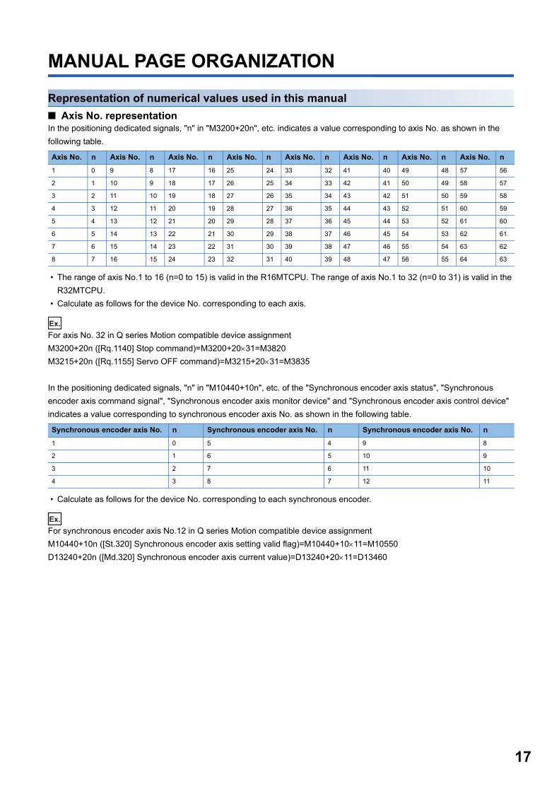
■ Axis No. representationIn the positioning dedicated signals, "n" in "M3200+20n", etc. indicates a value corresponding to axis No. as shown in the
following table.
• The range of axis No.1 to 16 (n=0 to 15) is valid in the R16MTCPU. The range of axis No.1 to 32 (n=0 to 31) is valid in the
R32MTCPU.
• Calculate as follows for the device No. corresponding to each axis.
Ex.
For axis No. 32 in Q series Motion compatible device assignment
M3200+20n ([Rq.1140] Stop command)=M3200+2031=M3820
M3215+20n ([Rq.1155] Servo OFF command)=M3215+2031=M3835
In the positioning dedicated signals, "n" in "M10440+10n", etc. of the "Synchronous encoder axis status", "Synchronous
encoder axis command signal", "Synchronous encoder axis monitor device" and "Synchronous encoder axis control device"
indicates a value corresponding to synchronous encoder axis No. as shown in the following table.
• Calculate as follows for the device No. corresponding to each synchronous encoder.
Ex.
For synchronous encoder axis No.12 in Q series Motion compatible device assignment
M10440+10n ([St.320] Synchronous encoder axis setting valid flag)=M10440+1011=M10550
D13240+20n ([Md.320] Synchronous encoder axis current value)=D13240+2011=D13460
Axis No. n Axis No. n Axis No. n Axis No. n Axis No. n Axis No. n Axis No. n Axis No. n
1 0 9 8 17 16 25 24 33 32 41 40 49 48 57 56
2 1 10 9 18 17 26 25 34 33 42 41 50 49 58 57
3 2 11 10 19 18 27 26 35 34 43 42 51 50 59 58
4 3 12 11 20 19 28 27 36 35 44 43 52 51 60 59
5 4 13 12 21 20 29 28 37 36 45 44 53 52 61 60
6 5 14 13 22 21 30 29 38 37 46 45 54 53 62 61
7 6 15 14 23 22 31 30 39 38 47 46 55 54 63 62
8 7 16 15 24 23 32 31 40 39 48 47 56 55 64 63
Synchronous encoder axis No. n Synchronous encoder axis No. n Synchronous encoder axis No. n
1 0 5 4 9 8
2 1 6 5 10 9
3 2 7 6 11 10
4 3 8 7 12 11
17
18
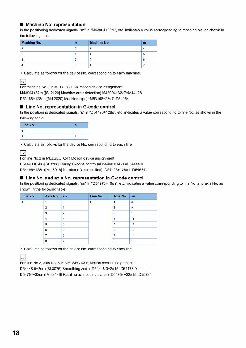
■ Machine No. representationIn the positioning dedicated signals, "m" in "M43904+32m", etc. indicates a value corresponding to machine No. as shown in
the following table.
• Calculate as follows for the device No. corresponding to each machine.
Ex.
For machine No.8 in MELSEC iQ-R Motion device assignment
M43904+32m ([St.2120] Machine error detection) M43904+327=M44128
D53168+128m ([Md.2020] Machine type)=M53168+287=D54064
■ Line No. representation in G-code controlIn the positioning dedicated signals, "s" in "D54496+128s", etc. indicates a value corresponding to line No. as shown in the
following table.
• Calculate as follows for the device No. corresponding to each line.
Ex.
For line No.2 in MELSEC iQ-R Motion device assignment
D54440.0+4s ([St.3208] During G-code control)=D54440.0+41=D54444.0
D54496+128s ([Md.3016] Number of axes on line)=D54496+1281=D54624
■ Line No. and axis No. representation in G-code controlIn the positioning dedicated signals, "sn" in "D54278+16sn", etc. indicates a value corresponding to line No. and axis No. as
shown in the following table.
• Calculate as follows for the device No. corresponding to each line.
Ex.
For line No.2, axis No. 8 in MELSEC iQ-R Motion device assignment
D54448.0+2sn ([St.3076] Smoothing zero)=D54448.0+215=D54478.0
D54754+32sn ([Md.3146] Rotating axis setting status)=D54754+3215=D55234
Machine No. m Machine No. m
1 0 5 4
2 1 6 5
3 2 7 6
4 3 8 7
Line No. s
1 0
2 1
Line No. Axis No. sn Line No. Axis No. sn
1 1 0 2 1 8
2 1 2 9
3 2 3 10
4 3 4 11
5 4 5 12
6 5 6 13
7 6 7 14
8 7 8 15

Representation of device No. used in this manualThe "R" and "Q" beside the device No. of positioning dedicated signals such as "[Rq.1140] Stop command (R: M34480+32n/
Q: M3200+20n)" indicate the device No. for the device assignment methods shown below. When "R" and "Q" are not beside
the device No., the device No. is the same for both device assignment methods.
Symbol Device assignment method
R MELSEC iQ-R Motion device assignment
Q Q series Motion compatible device assignment
19

20
1 OVERVIEW
1.1 Performance Specifications
Motion SFC performance specifications
*1 For operating system software version "09" or earlier, 4096k bytes.*2 For operating system software version "09" or earlier, 256 (No.0 to 255).*3 For operating system software version "09" or earlier, up to 256.*4 For operating system software version "08" or earlier, up to 256 steps.
Item R64MTCPU/R32MTCPU/R16MTCPU
Motion SFC
program capacity
Code total
(Motion SFC chart + Operation control + Transition)
8192k bytes*1
Motion SFC
program
Number of Motion SFC programs 512 (No.0 to 511)*2
Motion SFC chart size/program Up to 64k bytes (Included Motion SFC chart comments)
Number of Motion SFC steps/program Up to 4094 steps
Number of selective branches/branch 255
Number of parallel branches/branch 255
Parallel branch nesting Up to 4 levels
Operation control
program (F/FS)/
Transition
program (G)
Number of operation control programs 4096 with F(Once execution type) and FS(Scan execution type)
combined. (F/FS0 to F/FS4095)
Number of transition programs 4096(G0 to G4095)
Code size/program Up to approx. 128k bytes (65534 steps)
Number of blocks(line)/program Up to 8192 blocks (in the case of 8 steps(min)/blocks)
Number of characters/block Up to 1020 (comment included)
Number of operand/block Up to 510 (operand: constants, word device, bit devices)
( ) nesting/block Up to 32 levels
Descriptive
expression
Operation control program Calculation expression, bit conditional expression, branch/repetition
processing
Transition program Calculation expression/bit conditional expression/comparison conditional
expression
Execute
specification
Number of multi execute programs Up to 512*3
Number of multi active steps Up to 1024 steps*4/all programs
Executed task Normal task Execute in main cycle of Motion CPU
Event task
(Execution can be
masked.)
Fixed cycle Execute in fixed cycle (0.222ms, 0.444ms, 0.888ms, 1.777ms, 3.555ms,
7.111ms, 14.222ms)
External interrupt Executes when the input set to the event task factor in the input module
controlled by the Motion CPU (16 points) turns ON.
PLC interrupt Execute with interrupt instruction (M(P).GINT/D(P).GINT) from PLC CPU.
NMI task Executes when the input set to the NMI task factor in the input module
controlled by the Motion CPU (16 points) turns ON.
1 OVERVIEW1.1 Performance Specifications

1
Operation control/transition control specificationsTable of the operation control/transition control specifications
■ Expression
■ Bit devices: Usable, : Unusable
Restrictions on write-enabled bit devices
• Write to device X is allowed only in a device other than the actual input device.
• Special register, special relay has predetermined applications in the system. Do not perform write to other
than the user setting device.
■ Word devices: Usable, : Unusable
Restrictions on write-enabled word devices
• Special register has predetermined applications in the system. Do not perform write to other than the user-
set device.
Specifications Remark
Calculation expression Returns a numeric result.
Expressions for calculating indirectly specified data using constants and word devices.
D100+1, SIN(D100), etc.
Conditional
expression
Bit conditional
expression
Returns a true or false result.
Expression for judging ON or OFF of bit device.
M0, !M0, M1*M0,
(M1+M2)*(!M3+M4), etc.
Comparison conditional
expression
Expressions for comparing indirectly specified data and calculation expressions using
constants and word devices.
D100==100
D10<D102+D10, etc.
Device Symbol Accessibility Usable tasks Description exampleRead Write Normal Event NMI
Input X X100
Output Y Y100
Internal relay M M20
Link relay B B3FF
Annunciator F F0
Data register D D0.A
Link register W W1F.A
Motion register # #0.A
Special relay SM SM0
Special register SD SD0.A
CPU buffer memory access device U3E\G U3E0\G200.A
CPU buffer memory access device (fixed scan communication area) U3E\HG U3E0\HG200.A
Module access device U\G U0\G10200.A
Devices Symbol Accessibility Usable tasks Description exampleRead Write Normal Event NMI
Data register D DOL
Link register W W1F:F
Motion register # #0F
Special register SD SD0
CPU buffer memory access device U3E\G U3E0\G100L
CPU buffer memory access device (fixed scan communication area) U3E\HG U3E0\HG100L
Module access device U\G U0\G10100L
1 OVERVIEW1.1 Performance Specifications 21

22
■ Data type
■ Constant
■ Read/write response of input, output
Specifications Remark
(None) 16-bit integer type (signed) -32768 to 32767 K10, D100, etc.
16-bit integer type (unsigned) 0 to 65535
L 32-bit integer type (signed) -2147483648 to 2147483647 2000000000, W100L, etc.
32-bit integer type (unsigned) 0 to 4294967295
F 64-bit floating-point type (double precision real number type) IEEE format 1.23, #10F, etc.
Specifications Remark
K Decimal
constant
The above data type symbol 'L' or '. (decimal point)' provided at the end indicates the
data type. The constant without the data type is regarded as the applicable minimum
type.
K-100, H0FFL, etc.
'K' may be omitted.
H Hexadecimal
constant
Specifications Remark
Input response Direct read control at instruction execution.
Output response Direct write control at instruction execution.
1 OVERVIEW1.1 Performance Specifications

1
Table of the operation control/transition instruction: Usable, : UnusableClassification Symbol Function Format Basic steps
Usable step
Y/N transition's conditional expression
Section of reference
F/FS
G
Binary operation = Substitution (D)=(S) 8 Page 135
Substitution: =
+ Addition (S1)+(S2) 7 Page 137
Addition: +
- Subtraction (S1)-(S2) 7 Page 138
Subtraction: -
* Multiplication (S1)*(S2) 7 Page 139
Multiplication: *
/ Division (S1)/(S2) 7 Page 140
Division: /
% Remainder (S1)%(S2) 7 Page 141
Remainder: %
Bit operation ~ Bit inversion (complement) ~(S) 4 Page 142 Bit
inversion
(Complement): ~
& Bit logical AND (S1)&(S2) 7 Page 143 Bit
logical AND: &
| Bit logical OR (S1)|(S2) 7 Page 144 Bit
logical OR: |
^ Bit exclusive logical OR (S1)^(S2) 7 Page 145 Bit
exclusive logical OR:
^
>> Bit right shift (S1)>>(S2) 7 Page 146 Bit
right shift: >>
<< Bit left shift (S1)<<(S2) 7 Page 147 Bit left
shift: <<
Sign - Sign inversion
(complement of 2)
-(S) 4 Page 148 Sign
inversion
(Complement of 2): -
1 OVERVIEW1.1 Performance Specifications 23

24
Standard function SIN Sine SIN(S) 4 Page 149 Sine:
SIN
COS Cosine COS(S) 4 Page 150
Cosine: COS
TAN Tangent TAN(S) 4 Page 151
Tangent: TAN
ASIN Arcsine ASIN(S) 4 Page 152
Arcsine: ASIN
ACOS Arccosine ACOS(S) 4 Page 153
Arccosine: ACOS
ATAN Arctangent ATAN(S) 4 Page 154
Arctangent: ATAN
SQRT Square root SQRT(S) 4 Page 155
Square root: SQRT
LN Natural logarithm LN(S) 4 Page 156
Natural logarithm: LN
EXP Exponential operation EXP(S) 4 Page 157
Exponential
operation: EXP
ABS Absolute value ABS(S) 4 Page 158
Absolute value: ABS
RND Round-off RND(S) 4 Page 159
Round-off: RND
FIX Round-down FIX(S) 4 Page 160
Round-down: FIX
FUP Round-up FUP(S) 4 Page 161
Round-up: FUP
BIN BCDBIN conversion BIN(S) 4 Page 162 BCD -
> BIN conversion:
BIN
BCD BINBCD conversion BCD(S) 4 Page 163 BIN ->
BCD conversion:
BCD
Data control SCL 16-bit integer type scaling SCL(S1),(S2),(S3),(D) 15 Page 164 16-bit
integer type scaling:
SCL
DSCL 32-bit integer type scaling DSCL(S1),(S2),(S3),(D) 15 Page 168 32-bit
integer type scaling:
DSCL
Classification Symbol Function Format Basic steps
Usable step
Y/N transition's conditional expression
Section of reference
F/FS
G
1 OVERVIEW1.1 Performance Specifications

1
Type conversion SHORT Convert into 16-bit integertype (signed)
SHORT(S) 4 Page 171
Signed 16-bit integer
value conversion:
SHORT
USHORT Convert into 16-bit integer
type (unsigned)
USHORT(S) 4 Page 172
Unsigned 16-bit
integer value
conversion:
USHORT
LONG Convert into 32-bit integer
type (signed)
LONG(S) 4 Page 174
Signed 32-bit integer
value conversion:
LONG
ULONG Convert into 32-bit integer
type (unsigned)
ULONG(S) 4 Page 175
Unsigned 32-bit
integer value
conversion: ULONG
FLOAT Regard as signed data
and convert into 64-bit
floating point type
FLOAT(S) 4 Page 177
Signed 64-bit
floating-point value
conversion: FLOAT
UFLOAT Regard as unsigned data
and convert into 64-bit
floating point type
UFLOAT(S) 4 Page 178
Unsigned 64-bit
floating-point value
conversion: UFLOAT
DFLT Floating-point value
conversion 32-bit into 64-
bit
DFLT(S) 4 Page 179
Floating-point value
conversion 32-bit
into 64-bit: DFLT
SFLT Floating-point value
conversion 64-bit into 32-
bit
SFLT(S) 4 Page 180
Floating-point value
conversion 64-bit
into 32-bit: SFLT
Bit device status (None) ON (normally open
contact)
(S) 4 Page 181 ON
(Normally open
contact): (None)
! OFF (normally closed
contact)
!(S) 4 Page 182 OFF
(Normally closed
contact): !
Bit device control SET Device set SET(D) 5 Page 183
Device set: SETSET(D)=(conditional
expression)
8
RST Device reset RST(D) 5 Page 185
Device reset: RSTRST(D)=(conditional
expression)
8
DOUT Device output DOUT(D),(S) 8 Page 186
Device output:
DOUT
DIN Device input DIN(D),(S) 8 Page 187
Device input: DIN
OUT Bit device output OUT(D)=(conditional
expression)
8 Page 188 Bit
device output: OUT
Classification Symbol Function Format Basic steps
Usable step
Y/N transition's conditional expression
Section of reference
F/FS
G
1 OVERVIEW1.1 Performance Specifications 25

26
Logical operation (None) Logical acknowledgment (Conditional expression) 0 Page 189
Logical
acknowledgement:
(None)
! Logical negation !(Conditional expression) 4 Page 190
Logical negation: !
* Logical AND (Conditional expression) *
(conditional expression)
7 Page 191
Logical AND: *
+ Logical OR (Conditional expression) +
(conditional expression)
7 Page 192
Logical OR: +
Comparison
operation
== Equal to (Conditional expression) ==
(conditional expression)
7 Page 193 Equal
to: ==
!= Not equal to (Conditional expression) !=
(conditional expression)
7 Page 194 Not
equal to: !=
< Less than (Conditional expression) <
(conditional expression)
7 Page 195 Less
than: <
<= Less than or equal to (Conditional expression) <=
(conditional expression)
7 Page 196 Less
than or equal to: <=
> More than (Conditional expression) >
(conditional expression)
7 Page 197 More
than: >
>= More than or equal to (Conditional expression) >=
(conditional expression)
7 Page 198 More
than or equal to: >=
Program control IF - ELSE -
IEND
Conditional branch control IF(S)
ELSE
IEND
IF: 8
ELSE: 5
IEND: 1
Page 199
Conditional branch
control: IF - ELSE -
IEND
SELECT -
CASE -
SEND
Selective branch control SELECT
CASE(S1)
CEND
CASE(Sn)
CEND
CLELSE
CEND
SEND
SELECT: 1
CASE: 8
CEND: 5
CLELSE: 1
SEND: 1
Page 201
Selective branch
control: SELECT -
CASE - SEND
FOR -
NEXT
Repeat control with
specified count
FOR(D)=(S1) TO (S2)
STEP(S3)
NEXT
FOR: 18
NEXT: 15
Page 203
Repeat control with
specified count: FOR
- NEXT
BREAK Force termination of
repeat control
BREAK 5 Page 205
Forced termination of
repeat control:
BREAK
Classification Symbol Function Format Basic steps
Usable step
Y/N transition's conditional expression
Section of reference
F/FS
G
1 OVERVIEW1.1 Performance Specifications

1
Motion dedicatedfunction
CHGV Speed change request CHGV((S1),(S2)) 7 Page 206 Speed
change request:
CHGV
CHGVS Command generation axis
speed change request
CHGVS((S1),(S2)) 7 Page 210
Command
generation axis
speed change
request: CHGVS
CHGT Torque limit value change
request
CHGT((S1),(S2),(S3)) 10 Page 214
Torque limit value
change request:
CHGT
CHGP Target position change
request
CHGP((S1),(S2),(S3)) 11 Page 216 Target
position change
request: CHGP
MCNST Machine program
operation start request
MCNST((S1),(S2)) 7 Page 223
Machine program
operation start
request: MCNST
Advanced
synchronous
control dedicated
function
CAMRD Cam data read CAMRD(S1),(S2),(n),(D),
(S3)
16 Page 225 Cam
data read: CAMRD
CAMWR Cam data write CAMWR(S1),(S2),(n),(S3),
(D)
16 Page 229 Cam
data write: CAMWR
CAMMK Cam auto-generation CAMMK(S1),(S2),(S3),(D) 13 Page 233 Cam
auto-generation:
CAMMK
CAMPSCL Cam position calculation CAMPSCL(S1),(S2),(D) 12 Page 245 Cam
position calculation:
CAMPSCL
Vision system
dedicated
function
MVOPEN Open line MVOPEN(S1),(S2) 8 Page 248 Open
line: MVOPEN
MVLOAD Load a program MVLOAD(S1),(S2) 8 Page 249 Load
a program: MVLOAD
MVTRG Send an image acquisition
trigger
MVTRG(S1),(S2) 8 Page 250 Send
an image acquisition
trigger: MVTRG
MVPST Start a program MVPST(S1),(S2) 8 Page 251 Start a
program: MVPST
MVIN Input data MVIN(S1),(S2),(D),(S3) 15 or more Page 252 Input
data: MVIN
MVOUT Output data MVOUT(S1),(S2),(S3),(S4) 15 or more Page 254
Output data: MVOUT
MVFIN Reset a status storage
device
MVFIN(S) 6 Page 256 Reset
a status storage
device: MVFIN
MVCLOSE Close line MVCLOSE(S) 6 Page 257 Close
line: MVCLOSE
MVCOM Send a command for
native mode
MVCOM(S1),(S2),(D),(S3),
(S4)
19 or more Page 258 Send
a command for
native mode:
MVCOM
Add-on
dedicated
function
MCFUN Call add-on module MCFUN(S1),(S2),(D1),(D2) 11 or more Page 261 Call
add-on module:
MCFUN
Classification Symbol Function Format Basic steps
Usable step
Y/N transition's conditional expression
Section of reference
F/FS
G
1 OVERVIEW1.1 Performance Specifications 27

28
Rough calculation of single program for operation control/transition program2 + (2 + Total number of basic steps in 1 block + Number of 32-bit constants/1 block 1 + Number of 64-bit constants/1 block
3) Number of blocks (steps)
(1 step = 2 bytes)
Others EI Event task enable EI 1 Page 263 Event
task enable: EI
DI Event task disable DI 1 Page 264 Event
task disable: DI
NOP No operation NOP 1 Page 265 No
operation: NOP
BMOV Block transfer BMOV(D),(S),(n) 12 Page 266 Block
transfer: BMOV
FMOV Same data block transfer FMOV(D),(S),(n) 12 Page 268 Same
data block transfer:
FMOV
TO Write device data to buffer
memory
TO(D1),(D2),(S),(n) 14 Page 270 Write
device data to buffer
memory: TO
FROM Read device data from
buffer memory
FROM(D),(S1),(S2),(n) 14 Page 272 Read
device data from
buffer memory:
FROM
RTO Write buffer memory data
to head module
RTO(D1),(D2),(D3),(S),(n),
(D4)
21 Page 274 Write
buffer memory data
to head module:
RTO
RFROM Read buffer memory data
from head module
RFROM(D),(S1),(S2),(S3),
(n), (D1)
21 Page 277 Read
buffer memory data
from head module:
RFROM
TIME Time to wait TIME(S) 8 Page 280 Time
to wait: TIME
Classification Symbol Function Format Basic steps
Usable step
Y/N transition's conditional expression
Section of reference
F/FS
G
1 OVERVIEW1.1 Performance Specifications

1
1.2 Structure of the Motion CPU Program • By using the sequence program in the PLC CPU, Motion dedicated PLC instructions in the Motion CPU perform thefollowing controls.
• Motion CPU programs are created in the Motion SFC flowchart format. In positioning control, the motion control of servo
motors is performed using the servo programs specified by motion-control steps in a Motion SFC program.
• By setting the synchronous control parameter and starting the synchronous control for each output axis, the advanced
synchronous control is performed in synchronization with the input axis (servo input axis, command generation axis,
synchronous encoder axis).
• In machine control, the machine is controlled by using machine positioning data set in the devices, and the settings in the
machine control parameters for the machine type being used.
• Refer to the following for the details of Motion dedicated PLC instructions in the PLC CPU, Motion SFC programs, motion
control in positioning control, motion control in advanced synchronous control, and motion control in machine control.
• Start of Motion SFC program
• Start of servo program
• Direct positioning (perform positioning control by sequence program)
• Change of current value/speed/torque limit value
• Start of machine program operation
• Start of event task
Item Reference
Motion dedicated PLC instructions in the PLC CPU Page 30 MOTION DEDICATED PLC INSTRUCTION
Motion SFC program Page 97 MOTION SFC PROGRAMS
Motion control in positioning control (Servo program) MELSEC iQ-R Motion controller Programming Manual (Positioning Control)
Motion control in advanced synchronous control (Synchronous control
parameter)
MELSEC iQ-R Motion controller Programming Manual (Advanced Synchronous
Control)
Motion control in machine control (Machine control parameter) MELSEC iQ-R Motion controller Programming Manual (Machine Control)
1 OVERVIEW1.2 Structure of the Motion CPU Program 29
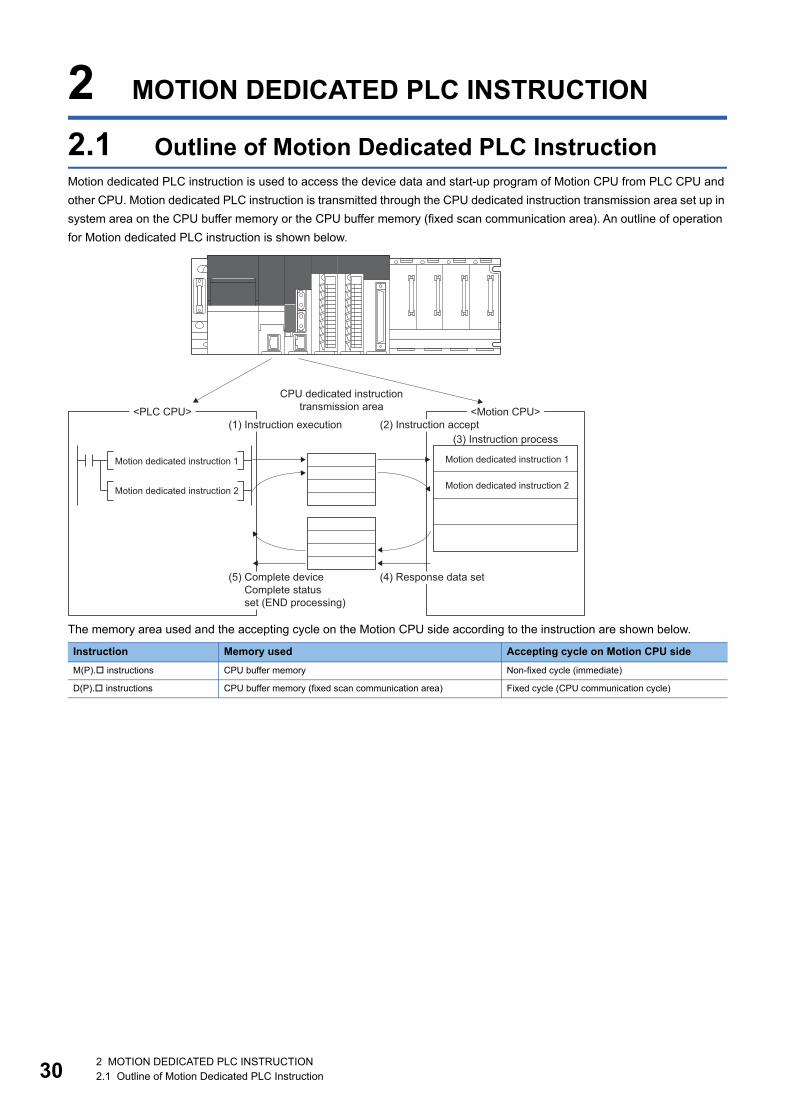
30
2 MOTION DEDICATED PLC INSTRUCTION
2.1 Outline of Motion Dedicated PLC InstructionMotion dedicated PLC instruction is used to access the device data and start-up program of Motion CPU from PLC CPU and
other CPU. Motion dedicated PLC instruction is transmitted through the CPU dedicated instruction transmission area set up in
system area on the CPU buffer memory or the CPU buffer memory (fixed scan communication area). An outline of operation
for Motion dedicated PLC instruction is shown below.
The memory area used and the accepting cycle on the Motion CPU side according to the instruction are shown below.
Instruction Memory used Accepting cycle on Motion CPU side
M(P). instructions CPU buffer memory Non-fixed cycle (immediate)
D(P). instructions CPU buffer memory (fixed scan communication area) Fixed cycle (CPU communication cycle)
<PLC CPU> <Motion CPU>
Motion dedicated instruction 1Motion dedicated instruction 1
Motion dedicated instruction 2
(3) Instruction process
CPU dedicated instructiontransmission area
(5) Complete deviceComplete statusset (END processing)
(1) Instruction execution (2) Instruction accept
(4) Response data set
Motion dedicated instruction 2
2 MOTION DEDICATED PLC INSTRUCTION2.1 Outline of Motion Dedicated PLC Instruction

2
2.2 Motion Dedicated PLC InstructionThe Motion dedicated PLC instruction that can be executed toward the Motion CPU is shown below.
Refer to the following for the details of sequence instruction configurations and data specification methods
used for programming Motion specialty sequence instructions.
MELSEC iQ-R Programming Manual (CPU Module Instructions, Standard Functions/Function Blocks)
Instruction Description Reference
M(P).□ D(P).□
M(P).SFCS D(P).SFCS Start request of the specified Motion SFC program Page 32 Motion SFC start request from
the PLC CPU to the Motion CPU: M(P).SFCS/
D(P).SFCS
M(P).SVST D(P).SVST Start request of the specified servo program Page 35 Servo program start request from
the PLC CPU to the Motion CPU: M(P).SVST/
D(P).SVST
M(P).SVSTD D(P).SVSTD Direct positioning start request Page 41 Direct positioning start instruction
from the PLC CPU to the Motion CPU:
M(P).SVSTD/D(P).SVSTD
M(P).CHGA D(P).CHGA Current value change request of the specified axis Page 54 Current value change instruction
from the PLC CPU to the Motion CPU:
M(P).CHGA/D(P).CHGA
M(P).CHGAS D(P).CHGAS Current value change request of the specified command generation axis Page 58 Current value change instruction
of command generation axis from the PLC
CPU to the Motion CPU: M(P).CHGAS/
D(P).CHGAS
M(P).CHGV D(P).CHGV Speed change request of the specified axis Page 62 Speed change instruction from
the PLC CPU to the Motion CPU: M(P).CHGV/
D(P).CHGV
M(P).CHGVS D(P).CHGVS Speed change request of the specified command generation axis Page 67 Speed change instruction of
command generation axis from the PLC CPU
to the Motion CPU: M(P).CHGVS/
D(P).CHGVS
M(P).CHGT D(P).CHGT Torque control value change request of the specified axis Page 72 Torque limit value change request
instruction from the PLC CPU to the Motion
CPU: M(P).CHGT/D(P).CHGT
M(P).MCNST D(P).MCNST Start request of machine program operation Page 76 Machine program operation start
request from the PLC CPU to the Motion CPU:
M(P).MCNST/D(P).MCNST
M(P).DDWR D(P).DDWR Write device data of the self CPU to the device of another Motion CPU MELSEC iQ-R Programming Manual (CPU
Module Instructions, Standard Functions/
Function Blocks)M(P).DDRD D(P).DDRD Read device data of another Motion CPU to the device of self CPU
M(P).BITWR D(P).BITWR Write bit operation to the bit device of another Motion CPU Page 80 Write bit device to the Motion
CPU: M(P).BITWR/D(P).BITWR
M(P).GINT D(P).GINT Execute request of an event task of Motion SFC program Page 84 Interrupt instruction to the other
CPU: M(P).GINT/D(P).GINT
2 MOTION DEDICATED PLC INSTRUCTION2.2 Motion Dedicated PLC Instruction 31

32
Motion SFC start request from the PLC CPU to the Motion CPU: M(P).SFCS/D(P).SFCS
M(P).SFCS/D(P).SFCS
■ Program
*1 An instruction should be described in each area.
■ Execution condition
Setting data
■ Description, range, setting side, data type
*1 Omission possible when both (d1) and (d2) are omitted.*2 Motion CPU cannot be set as CPU No.1 in the Multiple CPU configuration.*3 For operating system software version "09" or earlier, 0 to 255.
Ladder*1 FBD/LD*1 ST
ENO:=MP_SFCS(EN,UnHn,s,d1,d2);
ENO:=DP_SFCS(EN,UnHn,s,d1,d2);
ENO:=M_SFCS(EN,UnHn,s,d1,d2);
ENO:=D_SFCS(EN,UnHn,s,d1,d2);
Instruction Execution condition
MP.SFCS
DP.SFCS
M.SFCS
D.SFCS
Setting data Description Setting range Set by Data type Data type (label)
(UnHn) Start I/O No. (the first 3 digits when expressed in 4-digit hexadecimal) of
the target CPU*2
• CPU No.2: 3E1H
• CPU No.3: 3E2H
• CPU No.4: 3E3H
3E1H to 3E3H User 16-bit binary ANY16
(s) Motion SFC program No. to start. 0 to 511*3 User 16-bit binary ANY16
(d1)*1 Complete devices
• (d1+0): Device which make turn on for one scan at accept completion
of instruction.
• (d1+1): Device which make turn on for one scan at accept abnormal
completion of instruction. ("d1+0" also turns on at the abnormal
completion.)
System Bit ANYBIT_ARRAY
(d2)*1 Complete status storage device System Word ANY16
EN Execution condition (inputs the condition to control execution of the
instruction)
User Bit BOOL
ENO Execution result (outputs the execution result of the instruction) System Bit BOOL
Command(UnHn) (s)
Command(UnHn) (s) (d1) (d2)
EN
UnHn
s
ENO
d1
d2
2 MOTION DEDICATED PLC INSTRUCTION2.2 Motion Dedicated PLC Instruction

2
■ Usable devices: Usable, : Usable partly
*1 Setting data (UnHn) to (d2): Index qualification possible (except constant).*2 Omission possible when both (d1) and (d2) are omitted.*3 Local devices cannot be used.
Processing details
■ ControlsRequest to start the Motion SFC program of program No. specified with (s). The Motion SFC program can start any task
setting of the normal task, event task and NMI task.
■ OperationAn outline of operation between CPUs at the MP.SFCS and DP.SFCS instruction execution is shown below.
• MP.SFCS instruction
• DP.SFCS instruction
*1 Set in [System Parameter] [Multiple CPU settings] in GX Works3
Setting data*1
Internal devices (System, User)
File register Link direct device J□\□
Module access device U□\G□
Index registerZ□
Constant Others
Bit Word Bit Word Bit Word Bit Word Decimal K, Hexadecimal H
Real character string
(UnHn)
(s)
(d1)*2 *3 *3
(d2)*2 *3 *3
Sequence program
MP.SFCS instruction
Motion SFC program
END END
Complete device (d1+0)
ON
Status display device (d1+1)at the completion
CPU dedicated transmission(Non-fixed cycle)
ON
1 scan
Transfer
executed processing
ON: Abnormal completion only
Requestdata set
Responsedata set
Motion SFC
MP.SFCS execution
Sequence program
DP.SFCS instruction
ON DP.SFCS execution
Request data set
Motion SFC program
END END
Complete device (d1+0)
ON
Status display device (d1+1)at the completion
CPU dedicated transmission(fixed cycle)
Communicationcycle*1
1 scan
Transfer Transfer
Responsedata set
ON: Abnormal completion only
Motion SFCexecuted processing
2 MOTION DEDICATED PLC INSTRUCTION2.2 Motion Dedicated PLC Instruction 33
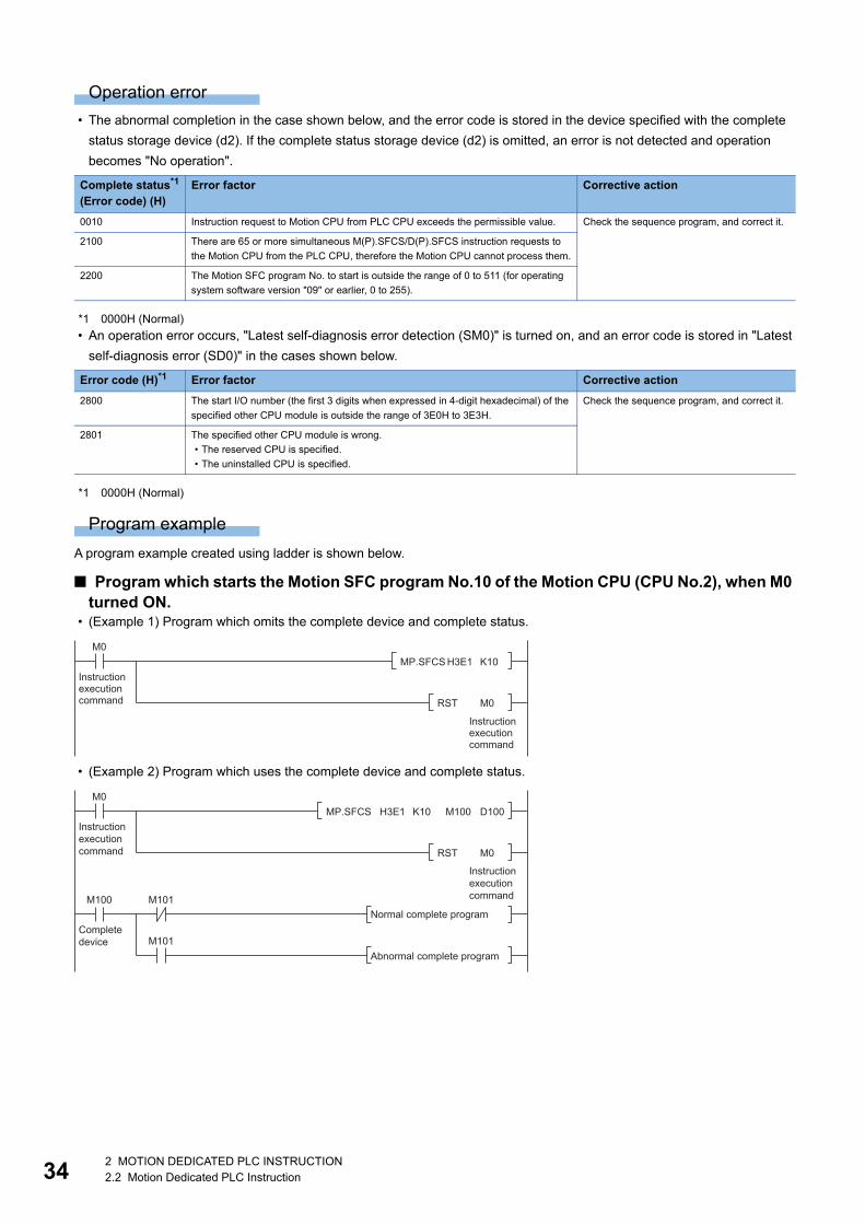
34
Operation error
• The abnormal completion in the case shown below, and the error code is stored in the device specified with the complete
status storage device (d2). If the complete status storage device (d2) is omitted, an error is not detected and operation
becomes "No operation".
*1 0000H (Normal)
• An operation error occurs, "Latest self-diagnosis error detection (SM0)" is turned on, and an error code is stored in "Latest
self-diagnosis error (SD0)" in the cases shown below.
*1 0000H (Normal)
Program example
A program example created using ladder is shown below.
■ Program which starts the Motion SFC program No.10 of the Motion CPU (CPU No.2), when M0 turned ON.
• (Example 1) Program which omits the complete device and complete status.
• (Example 2) Program which uses the complete device and complete status.
Complete status*1
(Error code) (H)Error factor Corrective action
0010 Instruction request to Motion CPU from PLC CPU exceeds the permissible value. Check the sequence program, and correct it.
2100 There are 65 or more simultaneous M(P).SFCS/D(P).SFCS instruction requests to
the Motion CPU from the PLC CPU, therefore the Motion CPU cannot process them.
2200 The Motion SFC program No. to start is outside the range of 0 to 511 (for operating
system software version "09" or earlier, 0 to 255).
Error code (H)*1 Error factor Corrective action
2800 The start I/O number (the first 3 digits when expressed in 4-digit hexadecimal) of the
specified other CPU module is outside the range of 3E0H to 3E3H.
Check the sequence program, and correct it.
2801 The specified other CPU module is wrong.
• The reserved CPU is specified.
• The uninstalled CPU is specified.
M0
Instructionexecutioncommand
Instructionexecutioncommand
MP.SFCS H3E1 K10
RST M0
M0
Instructionexecutioncommand
InstructionexecutioncommandM100
Completedevice
M101
M101
MP.SFCS H3E1 K10 M100 D100
Normal complete program
Abnormal complete program
RST M0
2 MOTION DEDICATED PLC INSTRUCTION2.2 Motion Dedicated PLC Instruction

2
Servo program start request from the PLC CPU to the Motion CPU: M(P).SVST/D(P).SVST
M(P).SVST/D(P).SVST
■ Program
*1 An instruction should be described in each area.
■ Execution condition
Setting data
■ Description, range, setting side, data type
*1 Omission possible when both (d1) and (d2) are omitted.*2 Motion CPU cannot be set as CPU No.1 in the Multiple CPU configuration.*3 n shows the numerical value correspond to axis No. (n=1 to 64)*4 For operating system software version "09" or earlier, 0 to 4095.*5 Use the methods shown below to enclose character string data depending on the programming language being used.
Ladder*1 FBD/LD*1 ST
ENO:=MP_SVST(EN,UnHn,s1,s2,d1,d2);
ENO:=DP_SVST(EN,UnHn,s1,s2,d1,d2);
ENO:=M_SVST(EN,UnHn,s1,s2,d1,d2);
ENO:=D_SVST(EN,UnHn,s1,s2,d1,d2);
Instruction Execution condition
MP.SVST
DP.SVST
M.SVST
D.SVST
Setting data Description Setting range Set by Data type Data type (label)
(UnHn) Start I/O No. (the first 3 digits when expressed in 4-digit hexadecimal) of
the target CPU*2
• CPU No.2: 3E1H
• CPU No.3: 3E2H
• CPU No.4: 3E3H
3E1H to 3E3H User 16-bit binary ANY16
(s1) Axis No.(Jn)*3 to start.
• R64MTCPU: J1 to J64
• R32MTCPU: J1 to J32
• R16MTCPU: J1 to J16
1 to 64 User Character
string*5ANYSTRING_SIN
GLE
(s2) Motion SFC program No. to start. 0 to 8191*4 User 16-bit binary ANY16
(d1)*1 Complete devices
• (d1+0): Device which make turn on for one scan at accept completion
of instruction.
• (d1+1): Device which make turn on for one scan at accept abnormal
completion of instruction. ("d1+0" also turns on at the abnormal
completion.)
System Bit ANYBIT_ARRAY
(d2)*1 Complete status storage device System Word ANY16
EN Execution condition (inputs the condition to control execution of the
instruction)
User Bit BOOL
ENO Execution result (outputs the execution result of the instruction) System Bit BOOL
Programming language Description method Description example
Ladder Enclose the character string in double quotation marks (" "). "J10"
FBD/LD Enclose the character string in single quotation marks (' '). 'J10'
ST
Command(UnHn) (s1) (s2)
Command(UnHn) (s1) (s2) (d1) (d2)
EN
UnHn
s1
ENO
d1
d2
s2
2 MOTION DEDICATED PLC INSTRUCTION2.2 Motion Dedicated PLC Instruction 35

36
■ Usable devices: Usable, : Usable partly
*1 Setting data (UnHn) to (d2): Index qualification possible (except constant).*2 Omission possible when both (d1) and (d2) are omitted.*3 Local devices cannot be used.
Processing details
■ Controls • Request to start the servo program specified with (s2) program No.
• It is necessary to take an inter-lock by the start accept flag of CPU buffer memory and user device so that multiple
instructions may not be executed toward the same axis of the same Motion CPU No.
Refer to the start accept flag (system area) for details of the start accept flag. (Page 87 Start accept flag
(System area))
■ OperationAn outline of operation between CPUs at the MP.SVST and DP.SVST instruction execution is shown below.
• MP.SVST instruction
Setting data*1
Internal devices (System, User)
File register Link direct device J□\□
Module access device U□\G□
Index registerZ□
Constant Others
Bit Word Bit Word Bit Word Bit Word Decimal K, Hexadecimal H
Real character string
(UnHn)
(s)
(d1)*2 *3 *3
(d2)*2 *3 *3
Requestdata set
ON MP.SVST executionSequence program
MP.SVST instruction
Servo program
END END
Axis start accept flag(System area)
ON
Complete device (d1+0)
ON
Status display device (d1+1)at the completion
CPU dedicated transmission(Non-fixed cycle)
1 scan
ON: Abnormal completion only
Transfer
Responsedata set
Servo program executed processing
2 MOTION DEDICATED PLC INSTRUCTION2.2 Motion Dedicated PLC Instruction

2
• DP.SVST instruction
*1 Set in [System Parameter] [Multiple CPU settings] in GX Works3
■ Setting of the starting axisThe starting axis being set to (s1) is set as "J + Axis No." in a character string.
Up to 12 axes can be set to (s1). Set them as shown below. Set "J" in a capital letter or small letter and use the axis No. set in
the servo network setting as the axis No. to start. Refer to the following for servo network settings.
MELSEC iQ-R Motion controller Programming Manual (Common)
Enclose the set character string (J + Axis No.) with double quotation marks (" ") for a ladder program, or with single quotation
marks (' ') for an FBD/ST program.
Also, the axis No. to start does not need to be in order.
Ex.
When multiple axes (Axis1, Axis2, Axis10, Axis11) are set.
If the start axis specified by (s1), and the axis No. specified in the servo program to be started are verified and match, the
servo program starts. If the specified axes do not match, a minor error (error code: 19FBH) occurs, and the servo program
does not start.
When an empty character string (" ", ' ') is specified to (s1), the axis specified in the servo program starts without verifying axis
No. When indirectly specifying an axis No. in the servo program, specify an empty character string (" ", ' ') to (s1).
Motion CPU (s1) usable range
R64MTCPU 1 to 64
R32MTCPU 1 to 32
R16MTCPU 1 to 16
Ladder FBD/LD ST
"J1J2J10J11" 'J1J2J10J11'
"j1j2j10j11" 'j1j2j10j11'
"J1 J2 J10 J11" 'J1 J2 J10 J11'
Sequence program
DP.SVST execution
ON DP.SVST execution
Request data set
Servo program
END END
Axis start accept flag(System area)
ON
Complete device (d1+0)
ON
Status display device (d1+1)at the completion
CPU dedicated transmission(Fixed cycle)
Communication cycle*1
1 scan
Transfer Transfer
Responsedata set
ON: Abnormal completion only
Servo program executed processing
2 MOTION DEDICATED PLC INSTRUCTION2.2 Motion Dedicated PLC Instruction 37

38
[When an empty character string (" ", ' ') is specified to (s1)]
When omitting the axis No., the timing of the start accept flag and start accept flag for the command
generation axis turning ON is slower than when the axis No. is set. (Page 87 Start accept flag (System
area))
• When axis No. is set: When instruction is received
• When axis No. is omitted: When instruction is analysed
[When "J + Axis No." is specified to (s1)]
When starting the START instruction with M(P).SVST/D(P).SVST, regardless of whether all start axes are set,
if one or more axis No. of the start axes is specified in each servo program instruction in the START
instruction, the servo program starts without error.
■ Start accept flag (System area)The complete status of start accept flag is stored in the address of start accept flag in the CPU buffer memory for target CPU.
CPU buffer memory address( ) is decimal address
Description
204H(516)
205H(517)
206H(518)
207H(519)
The start accept flag for 64 axes are stored corresponding to each bit.
Bits are actually set as the following:
• R64MTCPU: J1 to J64
• R32MTCPU: J1 to J32
• R16MTCPU: J1 to J16
OFF: Start accept enable
ON: Start accept disable
20EH(526)
20FH(527)
210H(528)
211H(529)
The command generation axis start accept flag for 64 axes are stored corresponding to each bit.
Bits are actually set as the following:
• R64MTCPU: J1 to J64
• R32MTCPU: J1 to J32
• R16MTCPU: J1 to J16
OFF: Start accept enable
ON: Start accept disable
204H(516) address
205H(517) address
J16
J32
b15
J1
J17
b0
J2
J18
206H(518) address J48 J33J34
207H(519) address J64 J49J50
b1b2
20EH(526) address
20FH(527) address
J16
J32
b15
J1
J17
b0
J2
J18
210H(528) address J48 J33J34
211H(529) address J64 J49J50
b1b2
2 MOTION DEDICATED PLC INSTRUCTION2.2 Motion Dedicated PLC Instruction

2
Operation error
• The abnormal completion in the case shown below, and the error code is stored in the device specified with the complete
status storage device (d2). If the complete status storage device (d2) is omitted, an error is not detected and operation
becomes "No operation".
*1 0000H (Normal)
• An operation error occurs, "Latest self-diagnosis error detection (SM0)" is turned on, and an error code is stored in "Latest
self-diagnosis error (SD0)" in the cases shown below.
*1 0000H (Normal)
Program example
A program example created using ladder is shown below.
■ Program which requests to start of the servo program No.10 toward Axis 1, Axis 2 of the Motion CPU (CPU No.2), when M0 turned ON
• (Example 1) Program which omits the complete device and complete status.
• (Example 2) Program which uses the complete device and complete status.
Complete status*1
(Error code) (H)Error factor Corrective action
0010 Instruction request to Motion CPU from PLC CPU exceeds the permissible value. Check the sequence program, and correct it.
2100 There are 257 or more simultaneous M(P).SVST/D(P).SVST/M(P).SVSTD/
D(P).SVSTD/M(P).CHGA/D(P).CHGA/M(P).CHGAS/D(P).CHGAS/
M(P).MCNST/D(P).MCNST instruction requests to the Motion CPU from the PLC
CPU, therefore the Motion CPU cannot process them.
2201 The servo program No. to execute is outside the range of 0 to 8191 (for operating
system software version "09" or earlier, 0 to 4095).
2202 Axis No. set by M(P).SVST/D(P).SVST instruction is wrong.
Error code (H)*1 Error factor Corrective action
2800 The start I/O number (the first 3 digits when expressed in 4-digit hexadecimal) of the
specified other CPU module is outside the range of 3E0H to 3E3H.
Check the sequence program, and correct it.
2801 The specified other CPU module is wrong.
• The reserved CPU is specified.
• The uninstalled CPU is specified.
M0
Instructionexecutioncommand
Instructionexecutioncommand
U3E1\G516.0
Start acceptflag of CPUNo.2(Axis 1)
U3E1\G516.1
Start acceptflag of CPUNo.2(Axis 2)
MP.SVST H3E1 K10"J1J2"
RST M0
MP.SVST H3E1 K10"J1J2" M100 D100
Normal complete programM100
Completedevice
M101
M101Abnormal complete program
M0
Instructionexecutioncommand
Instructionexecutioncommand
U3E1\G516.0
Start acceptflag of CPUNo.2(Axis 1)
U3E1\G516.1
Start acceptflag of CPUNo.2(Axis 2) RST M0
2 MOTION DEDICATED PLC INSTRUCTION2.2 Motion Dedicated PLC Instruction 39

40
■ Program which executes continuous start of the servo program No.11 toward Axis 1 of the Motion CPU (CPU No.2), while X0 is ON
■ Program which continuously executes the servo program No.10 toward Axis 1 of the Motion CPU (CPU No.2) and the servo program No.20 toward Axis 2, when M0 turned ON
MP.SVST H3E1 K11"J1" M100 D100
M100
Completedevice
X0 M10
Instructionexecutioncommand
Interlock
U3E1\G516.0
Start acceptflag of CPUNo.2(Axis 1)
Interlock
SET M10
Interlock
RST M10
M0
Instructionexecutioncommand
Instructionexecutioncommand
U3E1\G516.0
Start acceptflag of CPUNo.2(Axis 1)
MP.SVST H3E1 K10"J1"
MP.SVST H3E1 K20"J2"
RST M0
U3E1\G516.1
Start acceptflag of CPUNo.2(Axis 1)
2 MOTION DEDICATED PLC INSTRUCTION2.2 Motion Dedicated PLC Instruction

2
Direct positioning start instruction from the PLC CPU to the Motion CPU: M(P).SVSTD/D(P).SVSTD
M(P).SVSTD/D(P).SVSTD
■ Program
*1 An instruction should be described in each area.
■ Execution condition
Setting data
■ Description, range, setting side, data type
*1 Motion CPU cannot be set as CPU No.1 in the Multiple CPU configuration.
Ladder*1 FBD/LD*1 ST
ENO:=MP_SVSTD(EN,UnHn,s1,s2,d1,d2);
ENO:=DP_SVSTD(EN,UnHn,s1,s2,d1,d2);
ENO:=M_SVSTD(EN,UnHn,s1,s2,d1,d2);
ENO:=D_SVSTD(EN,UnHn,s1,s2,d1,d2);
Instruction Execution condition
MP.SVSTD
DP.SVSTD
M.SVSTD
D.SVSTD
Setting data Description Setting range Set by Data type Data type (label)
(UnHn) Start I/O No. (the first 3 digits when expressed in 4-digit hexadecimal) of
the target CPU*1
• CPU No.2: 3E1H
• CPU No.3: 3E2H
• CPU No.4: 3E3H
3E1H to 3E3H User 16-bit binary ANY16
(s1) First device of the self CPU where the control data is stored. Page 42
Control data
User Word ANY16
(s2) First device of the self CPU where the positioning data area is stored. Page 43
Positioning data
area
User Word ANY16
(d1) Device of the following target Motion CPU
• Bit device of the target Motion CPU used for fixed position stop
command
• Word device of the target Motion CPU that stores the position follow-
up address
When not using for the above devices, specify an empty character
string (" ", ' ').
User Character
string*2ANYSTRING_SIN
GLE
(d2) Complete devices
• (d2+0): Device which make turn on for one scan at completion of
instruction.
• (d2+1): Device which make turn on for one scan at abnormal
completion of instruction. ("d2+0" also turns on at the abnormal
completion.)
System Bit ANYBIT_ARRAY
EN Execution condition (inputs the condition to control execution of the
instruction)
User Bit BOOL
ENO Execution result (outputs the execution result of the instruction) System Bit BOOL
Command(UnHn) (s1) (s2) (d1) (d2)
EN
UnHn
s1
ENO
d2
s2
d1
2 MOTION DEDICATED PLC INSTRUCTION2.2 Motion Dedicated PLC Instruction 41

42
*2 Use the methods shown below to enclose character string data depending on the programming language being used.
■ Usable devices: Usable, : Usable partly
*1 Except for setting data (d1), index qualification possible (except constant).*2 Local devices cannot be used.
■ Control data
Programming language Description method Description example
Ladder Enclose the character string in double quotation marks (" "). "M100"
FBD/LD Enclose the character string in single quotation marks (' '). 'M100'
ST
Setting data*1
Internal devices (System, User)
File register Link direct device J□\□
Module access device U□\G□
Index registerZ□
Constant Others
Bit Word Bit Word Bit Word Bit Word Decimal K, Hexadecimal H
Real character string
(UnHn)
(s1) *2 *2
(s2)
(d1)
(d2) *2 *2
Device (s1) Item Setting data Setting range Set by
+0 Complete status The status at the instruction completion is stored.
0: No error (Normal completion)
Except 0: Error code
System
+1 Number of positioning data
points
Set the size of the positioning data area in units of words. 14 to 2044 User
2 MOTION DEDICATED PLC INSTRUCTION2.2 Motion Dedicated PLC Instruction

2
■ Positioning data area
Device (s2)*1 Name Description Setting range
+0 Positioning type/Number of points(R) Set the number of points for positioning
points when starting continuous trajectory
control (CPSTART).
Set "0" for a control other than continuous
trajectory control (CPSTART).
0: Start a control other than continuous
trajectory control (CPSTART).
1 to 128: Start continuous trajectory control
(CPSTART).
+1 Positioning data items setting Set the positioning data used to start
positioning. Valid/Invalid is set in units of
bits.
0: Invalid
1: Valid
(Page 47 Setting of positioning data
items)
+2 Positioning data item No.1 Set the value of positioning data in units of
two words
Range of the data item set to "1: Valid" in
setting of positioning data items
(Page 47 Setting of positioning data
items)
+3
+(2V) Positioning data item No.(V)
+(2V+1)
+(2V+2) Axis 1
data
Axis No.. Set the axis No. R64MTCPU: 1 to 64, 1001 to 1064*2
R32MTCPU: 1 to 32, 1001 to 1032*2
R16MTCPU: 1 to 16, 1001 to 1016*2
+(2V+3) Unusable Set to "0" 0
+(2V+4) Positioning
point No.1
[Da.2] Control mode/
[Da.29] Interpolation
axis speed designation
Set the control mode and interpolation
axis speed designation method.
Page 48 Positioning point data
+(2V+5) [Da.10] M-code Set M-code.
Set the number of pitches against the
linear axis during helical interpolation.
M-code: 0 to 32767
Number of pitches: 0 to 999
+(2V+6) [Da.11] Dwell time Set the dwell time 0 to 5000 [ms]
+(2V+7) Torque limit value
during operation*3Set the torque limit value for every point 1 to 10000 [0.1%]
+(2V+8) [Da.8] Command
speed
Set the positioning speed mm: 1 to 60000000010-2[mm/min]
inch: 1 to 60000000010-3[inch/min]
degree: 1 to 214748364710-3[degree/min]*4
pulse: 1 to 2147483647[pulse/s]
+(2V+9)
+(2V+10) [Da.6] Positioning
address/Travel value
Set the positioning address/travel value -2147483648 to 2147483647
[Optional units]+(2V+11)
+(2V+12) [Da. 7] Arc address Set auxiliary point/central point address/
radius during circular interpolation
-2147483648 to 2147483647
[Optional units]+(2V+13)
+(2V+10R-6) Positioning
point
No.(R)
[Da.2] Control mode/
[Da.29] Interpolation
axis speed designation
The number of positioning points set in
"Positioning type/Number of points" is
valid.
When "0" is set, only "positioning point No.
1" is valid.
Page 48 Positioning point data
+(2V+10R-5) [Da.10] M-code M-code: 0 to 32767
Number of pitches: 0 to 999
+(2V+10R-4) [Da.11] Dwell time 0 to 5000 [ms]
+(2V+10R-3) Torque limit value
during operation*31 to 10000 [0.1%]
+(2V+10R-2) [Da.8] Command
speed
mm: 1 to 60000000010-2[mm/min]
inch: 1 to 60000000010-3[inch/min]
degree: 1 to 214748364710-3[degree/min]*4
pulse: 1 to 2147483647[pulse/s]
+(2V+10R-1)
+(2V+10R) [Da.6] Positioning
address/Travel value
-2147483648 to 2147483647
[Optional units]+(2V+10R+1)
+(2V+10R+2) [Da. 7] Arc address -2147483648 to 2147483647
[Optional units]+(2V+10R+3)
2 MOTION DEDICATED PLC INSTRUCTION2.2 Motion Dedicated PLC Instruction 43

44
+(2V+10R+4) Axis 2
data
Axis No. The number of positioning points set in
"Positioning type/Number of points" is
valid.
When "0" is set, only "positioning point No.
1" is valid.
R64MTCPU: 1 to 64, 1001 to 1064*2
R32MTCPU: 1 to 32, 1001 to 1032*2
R16MTCPU: 1 to 16, 1001 to 1016*2
+(2V+10R+5) Unusable 0
+(2V+10R+6) Positioning
point No.1
[Da.2] Control mode/
[Da.29] Interpolation
axis speed designation
Page 48 Positioning point data
+(2V+10R+7) [Da.10] M-code M-code: 0 to 32767
Number of pitches: 0 to 999
+(2V+10R+8) [Da.11] Dwell time 0 to 5000 [ms]
+(2V+10R+9) Torque limit value
during operation*31 to 10000 [0.1%]
+(2V+10R+10) [Da.8] Command
speed
mm: 1 to 60000000010-2[mm/min]
inch: 1 to 60000000010-3[inch/min]
degree: 1 to 214748364710-3[degree/min]*4
pulse: 1 to 2147483647[pulse/s]
+(2V+10R+11)
+(2V+10R+12) [Da.6] Positioning
address/Travel value
-2147483648 to 2147483647
[Optional units]+(2V+10R+13)
+(2V+10R+14) [Da. 7] Arc address -2147483648 to 2147483647
[Optional units]+(2V+10R+15)
+(2V+20R-4) Positioning
point
No.(R)
[Da.2] Control mode/
[Da.29] Interpolation
axis speed designation
Page 48 Positioning point data
+(2V+20R-3) [Da.10] M-code M-code: 0 to 32767
Number of pitches: 0 to 999
+(2V+20R-2) [Da.11] Dwell time 0 to 5000 [ms]
+(2V+20R-1) Torque limit value
during operation*31 to 10000 [0.1%]
+(2V+20R) [Da.8] Command
speed
mm: 1 to 60000000010-2[mm/min]
inch: 1 to 60000000010-3[inch/min]
degree: 1 to 214748364710-3[degree/min]*4
pulse: 1 to 2147483647[pulse/s]
+(2V+20R+1)
+(2V+20R+2) [Da.6] Positioning
address/Travel value
-2147483648 to 2147483647
[Optional units]+(2V+20R+3)
+(2V+20R+4) [Da. 7] Arc address -2147483648 to 2147483647
[Optional units]+(2V+20R+5)
+(2V+20R+6) Axis 3
data
Axis No. R64MTCPU: 1 to 64, 1001 to 1064*2
R32MTCPU: 1 to 32, 1001 to 1032*2
R16MTCPU: 1 to 16, 1001 to 1016*2
+(2V+20R+7) Unusable 0
+(2V+20R+8) Positioning
point No.1
[Da.2] Control mode/
[Da.29] Interpolation
axis speed designation
Page 48 Positioning point data
+(2V+20R+9) [Da.10] M-code M-code: 0 to 32767
Number of pitches: 0 to 999
+(2V+20R+10) [Da.11] Dwell time 0 to 5000 [ms]
+(2V+20R+11) Torque limit value
during operation*31 to 10000 [0.1%]
+(2V+20R+12) [Da.8] Command
speed
mm: 1 to 60000000010-2[mm/min]
inch: 1 to 60000000010-3[inch/min]
degree: 1 to 214748364710-3[degree/min]*4
pulse: 1 to 2147483647[pulse/s]
+(2V+20R+13)
+(2V+20R+14) [Da.6] Positioning
address/Travel value
-2147483648 to 2147483647
[Optional units]+(2V+20R+15)
+(2V+20R+16) [Da. 7] Arc address -2147483648 to 2147483647
[Optional units]+(2V+20R+17)
Device (s2)*1 Name Description Setting range
2 MOTION DEDICATED PLC INSTRUCTION2.2 Motion Dedicated PLC Instruction

2
*1 The "R" and "V" of "+ (2V+10R+3)" in the positioning data area explanation indicate the following items for the offset values. R: Positioning point V: Positioning data itemCalculate the offset value for each item as follows.(Example) When positioning data item is "5", and positioning point is "20"+(2V+10R+3) = (25+1020+3) = +213
*2 When using command generation axis
+(2V+30R-2) Axis 3
data
Positioning
point
No.(R)
[Da.2] Control mode/
[Da.29] Interpolation
axis speed designation
The number of positioning points set in
"Positioning type/Number of points" is
valid.
When "0" is set, only "positioning point No.
1" is valid.
Page 48 Positioning point data
+(2V+30R-1) [Da.10] M-code M-code: 0 to 32767
Number of pitches: 0 to 999
+(2V+30R) [Da.11] Dwell time 0 to 5000 [ms]
+(2V+30R+1) Torque limit value
during operation*31 to 10000 [0.1%]
+(2V+30R+2) [Da.8] Command
speed
mm: 1 to 60000000010-2[mm/min]
inch: 1 to 60000000010-3[inch/min]
degree: 1 to 214748364710-3[degree/min]*4
pulse: 1 to 2147483647[pulse/s]
+(2V+30R+3)
+(2V+30R+4) [Da.6] Positioning
address/Travel value
-2147483648 to 2147483647
[Optional units]+(2V+30R+5)
+(2V+30R+6) [Da. 7] Arc address -2147483648 to 2147483647
[Optional units]+(2V+30R+7)
+(2V+30R+8) Axis 4
data
Axis No. R64MTCPU: 1 to 64, 1001 to 1064*2
R32MTCPU: 1 to 32, 1001 to 1032*2
R16MTCPU: 1 to 16, 1001 to 1016*2
+(2V+30R+9) Unusable 0
+(2V+30R+10) Positioning
point No.1
[Da.2] Control mode/
[Da.29] Interpolation
axis speed designation
Page 48 Positioning point data
+(2V+30R+11) [Da.10] M-code M-code: 0 to 32767
Number of pitches: 0 to 999
+(2V+30R+12) [Da.11] Dwell time 0 to 5000 [ms]
+(2V+30R+13) Torque limit value
during operation*31 to 10000 [0.1%]
+(2V+30R+14) [Da.8] Command
speed
mm: 1 to 60000000010-2[mm/min]
inch: 1 to 60000000010-3[inch/min]
degree: 1 to 214748364710-3[degree/min]*4
pulse: 1 to 2147483647[pulse/s]
+(2V+30R+15)
+(2V+30R+16) [Da.6] Positioning
address/Travel value
-2147483648 to 2147483647
[Optional units]+(2V+30R+17)
+(2V+30R+18) [Da. 7] Arc address -2147483648 to 2147483647
[Optional units]+(2V+30R+19)
+(2V+40R) Positioning
point
No.(R)
[Da.2] Control mode/
[Da.29] Interpolation
axis speed designation
Page 48 Positioning point data
+(2V+40R+1) [Da.10] M-code M-code: 0 to 32767
Number of pitches: 0 to 999
+(2V+40R+2) [Da.11] Dwell time 0 to 5000 [ms]
+(2V+40R+3) Torque limit value
during operation*31 to 10000 [0.1%]
+(2V+40R+4) [Da.8] Command
speed
mm: 1 to 60000000010-2[mm/min]
inch: 1 to 60000000010-3[inch/min]
degree: 1 to 214748364710-3[degree/min]*4
pulse: 1 to 2147483647[pulse/s]
+(2V+40R+5)
+(2V+40R+6) [Da.6] Positioning
address/Travel value
-2147483648 to 2147483647
[Optional units]+(2V+40R+7)
+(2V+40R+8) [Da. 7] Arc address -2147483648 to 2147483647
[Optional units]+(2V+40R+9)
Device (s2)*1 Name Description Setting range
2 MOTION DEDICATED PLC INSTRUCTION2.2 Motion Dedicated PLC Instruction 45

46
*3 Only valid during continuous trajectory control, VPF/VPR, VVF/VVR. When setting torque limit in another control mode, set the torque limit value at start in positioning data item. When not using torque limit value during operation, set "0". When both torque limit during operation and torque limit at start are set in VVF/VVR, torque limit at start is valid.
*4 When the "speed control 10 multiplier speed setting for degree axis" is set to "valid", the setting range is 1 to 214748364710-2 [degree/min]
Processing details
■ Controls • Request a direct positioning start to the Motion CPU from the data stored in the positioning data area of the device of the
self CPU specified with (s2) and after.
• It is necessary to take an inter-lock by the start accept flag of CPU buffer memory and user device so that multiple
instructions may not be executed toward the same axis of the same Motion CPU No.
Refer to the start accept flag (system area) for details of the start accept flag. (Page 87 Start accept flag
(System area))
■ OperationAn outline of operation between CPUs at the MP.SVSTD and DP.SVSTD instruction execution is shown below.
• MP.SVSTD instruction
*1 Set in [Motion CPU Common parameter] [Basic Setting]
• DP.SVSTD instruction
*2 Set in [System Parameter] [Multiple CPU settings] in GX Works3*3 Set in [Motion CPU Common parameter] [Basic Setting]
Sequence program
MP.SVSTD instructionRequestdata set
Servo program
END END
Axis start accept flag(System area)
ON
Complete device (d2+0)
ON
Status display device (d2+1)at the completion
CPU dedicated transmission(Non-fixed cycle)
ON MP.SVSTD execution
Operation cycle *1
1 scan
Transfer
Responsedata set
ON: Abnormal completion only
Servo program executed processing
Sequence program
DP.SVSTD instruction
ON DP.SVSTD execution
Requestdata set
Servo program
END END
Axis start accept flag(CPU buffer memory)
ON
Complete device (d2+0)
ON
Status display device (d2+1)at the completion
CPU dedicated transmission(Fixed cycle)
Communication
Operation
1 scan
Transfer Transfer
Responsedata set
ON: Abnormal completion only
cycle*1
cycle*2
Servo program executed processing
2 MOTION DEDICATED PLC INSTRUCTION2.2 Motion Dedicated PLC Instruction
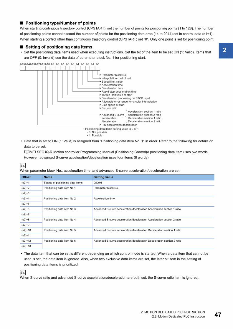
2
■ Positioning type/Number of pointsWhen starting continuous trajectory control (CPSTART), set the number of points for positioning points (1 to 128). The number
of positioning points cannot exceed the number of points for the positioning data area (14 to 2044) set in control data (s1+1).
When starting a control other than continuous trajectory control (CPSTART) set "0". Only one point is set for positioning point.
■ Setting of positioning data items • Set the positioning data items used when executing instructions. Set the bit of the item to be set ON (1: Valid). Items that
are OFF (0: Invalid) use the data of parameter block No. 1 for positioning start.
• Data that is set to ON (1: Valid) is assigned from "Positioning data item No. 1" in order. Refer to the following for details on
data to be set.
MELSEC iQ-R Motion controller Programming Manual (Positioning Control)A positioning data item uses two words.
However, advanced S-curve acceleration/deceleration uses four items (8 words).
Ex.
When parameter block No., acceleration time, and advanced S-curve acceleration/deceleration are set.
• The data item that can be set is different depending on which control mode is started. When a data item that cannot be
used is set, the data item is ignored. Also, when two exclusive data items are set, the later bit item in the setting of
positioning data items is prioritized.
Ex.
When S-curve ratio and advanced S-curve acceleration/deceleration are both set, the S-curve ratio item is ignored.
Offset Name Setting value
(s2)+1 Setting of positioning data items 0809H
(s2)+2 Positioning data item No.1 Parameter block No.
(s2)+3
(s2)+4 Positioning data item No.2 Acceleration time
(s2)+5
(s2)+6 Positioning data item No.3 Advanced S-curve acceleration/deceleration Acceleration section 1 ratio
(s2)+7
(s2)+8 Positioning data item No.4 Advanced S-curve acceleration/deceleration Acceleration section 2 ratio
(s2)+9
(s2)+10 Positioning data item No.5 Advanced S-curve acceleration/deceleration Deceleration section 1 ratio
(s2)+11
(s2)+12 Positioning data item No.6 Advanced S-curve acceleration/deceleration Deceleration section 2 ratio
(s2)+13
b15 b14 b13 b12 b11 b10 b9 b8 b7 b6 b5 b4 b3 b2 b1 b0
Parameter block No.Interpolation control unitSpeed limit valueAcceleration timeDeceleration timeRapid stop deceleration timeTorque limit value at startDeceleration processing on STOP inputAllowable error range for circular interpolationBias speed at startS-curve ratio
Advanced S-curveacceleration/decelerationFIN acceleration/deceleration
*: Positioning data items setting value is 0 or 1 • 0: Not possible • 1: Possible
Acceleration section 1 ratioAcceleration section 2 ratioDeceleration section 1 ratioDeceleration section 2 ratio
2 MOTION DEDICATED PLC INSTRUCTION2.2 Motion Dedicated PLC Instruction 47

48
■ Positioning point dataSet "[Da.2] Control mode", and "[Da.29] Interpolation axis speed designation" when performing positioning control.
• [Da.29] Interpolation axis speed designation
Setting value Description
0 or 1 Vector speed
2 Reference axis speed
3 Longest axis speed
b15 b14 b13 b12 b11 b10 b9 b8 b7 b6 b5 b4 b3 b2 b1 b0
[Da.29] Interpolation axis speed designation[Da.2] Control mode
2 MOTION DEDICATED PLC INSTRUCTION2.2 Motion Dedicated PLC Instruction

2
• [Da.2] Control mode
Positioning control Instruction symbol
Control description Setting value
Remark
Linear
interpolation
control
1 axis ABS-1 Absolute 1-axis positioning 01H ■Interpolation control*1
• When performing interpolation control,
set "[Da.2] Control mode" to "NOP" for
interpolation axes (axes other than the
reference axis) for the data of 1 to 4
axes. For the linear axis for helical
interpolation, set "ABS-1" or "INC-1".
When control mode settings are wrong,
a minor error (error code: 19FCH)
occurs, and positioning does not start.
■Continuous trajectory control
(CPSTART)
• The control modes that can be set to
"[Da.2] Control mode" are linear
interpolation control (ABS-1 to 4, INC-1
to 4), circular interpolation control
(ABS/INC), and helical interpolation
control (ABS/INC). If any other control
mode is set, a minor error (error code:
19FCH) occurs, and control does not
start.
• When performing circular interpolation
control or helical interpolation control
with 3 axes or more in continuous
trajectory control, set "[Da.2] Control
mode" to "0" for the resting axes (axes
that do not apply to interpolation).
• "[Da.29] Interpolation axis speed
designation" setting is ignored and is
always controlled at "vector speed".
INC-1 Incremental 1-axis positioning 02H
2 axis ABS-2 Absolute 2-axis positioning 0AH
INC-2 Incremental 2-axis positioning 0BH
3 axis ABS-3 Absolute 3-axis positioning 15H
INC-3 Incremental 3-axis positioning 16H
4 axis ABS-4 Absolute 4-axis positioning 1AH
INC-4 Incremental 4-axis positioning 1BH
Circular
interpolation
control
Auxiliary
point-
specified
ABS Absolute auxiliary point-specified circular interpolation 0DH
INC Incremental auxiliary point-specified circular interpolation 0EH
Central
point-
specified
ABS Absolute central point-specified circular interpolation CW 0FH
ABS Absolute central point-specified circular interpolation CCW 10H
INC Incremental central point-specified circular interpolation
CW
11H
INC Incremental central point-specified circular interpolation
CCW
12H
Radius-
specified
ABS Absolute radius-specified circular interpolation less than
CW 18030H
ABS Absolute radius-specified circular interpolation CW 180 or
more
31H
ABS Absolute radius-specified circular interpolation less than
CCW 18032H
ABS Absolute radius-specified circular interpolation CCW 180 or more
33H
INC Incremental radius-specified circular interpolation less than
CW 18034H
INC Incremental radius-specified circular interpolation CW 180 or more
35H
INC Incremental radius-specified circular interpolation less than
CCW 18036H
INC Incremental radius-specified circular interpolation CCW
180 or more
37H
Helical
interpolation
control
Auxiliary
point-
specified
ABH Absolute auxiliary point-specified helical interpolation 20H
INH Incremental auxiliary point-specified helical interpolation 21H
Central
point-
specified
ABH Absolute central point-specified helical interpolation CW 22H
ABH Absolute central point-specified helical interpolation CCW 23H
INH Incremental central point-specified helical interpolation CW 24H
INH Incremental central point-specified helical interpolation
CCW
25H
Radius-
specified
ABH Absolute radius-specified helical interpolation less than CW
18028H
ABH Absolute radius-specified helical interpolation CW 180 or
more
29H
ABH Absolute radius-specified helical interpolation less than
CCW 1802AH
ABH Absolute radius-specified helical interpolation CCW 180 or
more
2BH
INH Incremental radius-specified helical interpolation less than
CW 1802CH
INH Incremental radius-specified helical interpolation CW 180 or more
2DH
INH Incremental radius-specified helical interpolation less than
CCW 1802EH
INH Incremental radius-specified helical interpolation CCW 180 or more
2FH
2 MOTION DEDICATED PLC INSTRUCTION2.2 Motion Dedicated PLC Instruction 49

50
Fixed-Pitch
feed control
1 axis FEED1 1 Axis Fixed-Pitch Feed Control 03H
2 axis FEED2 2-axes linear interpolation fixed-pitch feed control 0CH
3 axis FEED3 3-axes linear interpolation fixed-pitch feed control 17H
Speed
control ()
Forward
rotation
VF Speed control () forward rotation start 04H
Reverse
rotation
VR Speed control () reverse rotation start 05H
Speed
control ()
Forward
rotation
VVF Speed control () forward rotation start 70H
Reverse
rotation
VVR Speed control () reverse rotation start 71H
Speed/
position
switching
control
Forward
rotation
VPF Speed/position switching control forward rotation start 06H • VPSTART instruction is not supported.
• If VPF/VPR instructions are executed
by M(P).SVSTD/D(P).SVSTD
instructions and VPSTART instruction
is executed by the Motion SFC
program, a minor error (error code:
19FCH) occurs.
Reverse
rotation
VPR Speed/position switching control reverse rotation start 07H
Speed
control with
fixed
position
stop
Forward
rotation
PVF Speed control with fixed position stop forward rotation start 73H • Set a bit device of the Motion CPU to
use for fixed position stop command to
(d1). If a valid device is not set to (d1),
error code (2225) is stored to the
complete status (s1+0), and control
does not start. When a number outside
the range is set, a minor error (error
code: 19FCH) occurs.
• Acceleration/deceleration time is set by
"acceleration time (b4)" of positioning
data items setting. If not set, error code
(2224) is stored to the complete status
(s1+0), and control does not start.
Reverse
rotation
PVR Speed control with fixed position stop reverse rotation start 74H
Position follow-up
control
PFSTART Position follow-up control start 75H Set a word device of the Motion CPU to
store the follow-up address to (d1). If a
valid device is not set to (d1), error code
(2225) is stored to the complete status
(s1+0), and control does not start. When
a number outside the range is set, a
minor error (error code: 19FCH) occurs.
Home position return ZERO Home position return start 76H Home position return is performed based
on home position return data. Data other
than "[Da.2] Control mode" is ignored.
High speed oscillation OSC High-speed oscillation 77H Set the high speed oscillation setting
items (starting angle, amplitude,
frequency) to the following positioning
point data.
• Amplitude: [Da.6] Positioning address/
Travel value
• Starting angle: [Da.7] Arc address
• Frequency: [Da.8] Command speed
NOP instruction NOP No operation 80H
Positioning control Instruction symbol
Control description Setting value
Remark
2 MOTION DEDICATED PLC INSTRUCTION2.2 Motion Dedicated PLC Instruction

2
*1 The data items set to the reference axis and interpolation axis are shown below.
: Must be set
: Set if required ("" when not required)
: "" or "" depending on control mode
: Setting not required (Setting value is ignored)
■ Start accept flag (System area)The complete status of start accept flag is stored in the address of start accept flag in the CPU buffer memory for target CPU.
Setting item Setting item for reference axis
Setting item for interpolation axis
Setting item for linear axis for helical interpolation
Same
positioning
point No.
[Da.2] Control mode (Set NOP) (Set ABS-1 or INC-1)
[Da.6] Positioning address/Travel value
[Da. 7] Arc address (circular interpolation, arc
axis of helical interpolation only
)
(arc axis only )
[Da.8] Command speed
[Da.10] M-code
[Da.11] Dwell time
[Da.29] Interpolation axis speed
designation
CPU buffer memory address( ) is decimal address
Description
204H(516)
205H(517)
206H(518)
207H(519)
The start accept flag for 64 axes are stored corresponding to each bit.
Bits are actually set as the following:
• R64MTCPU: J1 to J64
• R32MTCPU: J1 to J32
• R16MTCPU: J1 to J16
OFF: Start accept enable
ON: Start accept disable
20EH(526)
20FH(527)
210H(528)
211H(529)
The command generation axis start accept flag for 64 axes are stored corresponding to each bit.
Bits are actually set as the following:
• R64MTCPU: J1 to J64
• R32MTCPU: J1 to J32
• R16MTCPU: J1 to J16
OFF: Start accept enable
ON: Start accept disable
204H(516) address
205H(517) address
J16
J32
b15
J1
J17
b0
J2
J18
206H(518) address J48 J33J34
207H(519) address J64 J49J50
b1b2
20EH(526) address
20FH(527) address
J16
J32
b15
J1
J17
b0
J2
J18
210H(528) address J48 J33J34
211H(529) address J64 J49J50
b1b2
2 MOTION DEDICATED PLC INSTRUCTION2.2 Motion Dedicated PLC Instruction 51

52
Operation error
• The abnormal completion in the case shown below, and the error code is stored in the device specified with the complete
status storage device (s1+0).
*1 0000H (Normal)
• An operation error occurs, "Latest self-diagnosis error detection (SM0)" is turned on, and an error code is stored in "Latest
self-diagnosis error (SD0)" in the cases shown below.
*1 0000H (Normal)
Complete status*1
(Error code) (H)Error factor Corrective action
0010 Instruction request to Motion CPU from PLC CPU exceeds the permissible value. Check the sequence program, and correct it.
2100 There are 257 or more simultaneous M(P).SVST/D(P).SVST/M(P).SVSTD/
D(P).SVSTD/M(P).CHGA/D(P).CHGA/M(P).CHGAS/D(P).CHGAS/
M(P).MCNST/D(P).MCNST instruction requests to the Motion CPU from the PLC
CPU, therefore the Motion CPU cannot process them.
2209 Axis No. set by M(P).SVSTD/D(P).SVSTD instruction is wrong.
2220 Instruction area for M(P).SVSTD/D(P).SVSTD instructions is not enough. (There are
128 or more instructions in operation by M(P).SVSTD/D(P).SVSTD instructions)
2221 The positioning data area points for M(P).SVSTD/D(P).SVSTD instruction is wrong.
2222 Instructions for M(P).SVSTD/D(P).SVSTD instructions are only NOP or resting axes.
2224 Positioning data items that must be set in instructions by M(P).SVSTD/D(P).SVSTD
instructions have not been set.
2225 Character string data (d1) is wrong in M(P).SVSTD/D(P).SVSTD instructions.
Error code (H)*1 Error factor Corrective action
2800 The start I/O number (the first 3 digits when expressed in 4-digit hexadecimal) of the
specified other CPU module is outside the range of 3E0H to 3E3H.
Check the sequence program, and correct it.
2801 The specified other CPU module is wrong.
• The reserved CPU is specified.
• The uninstalled CPU is specified.
2 MOTION DEDICATED PLC INSTRUCTION2.2 Motion Dedicated PLC Instruction

2
Program example
A program example created using ladder is shown below.
■ Program which requests to start direct positioning corresponding to the following servo program in the Motion CPU (CPU No.2), when M0 turned ON
MOVP K0 D2000 Positioning type (A control other than continuous trajectory control)
Positioning data items setting(All invalid)
Axis No. (1)
Fixed at 0
Positioning control (ABS-1),Interpolation speed (vector speed)
M-code (not using)
Dwell time (not using)
Torque limit during operation(Invalid in ABS-1)
Command speed (100000[pulse/s])
Positioning address (100000[pulse])
Arc address (Invalid in ABS-1)
Positioning data area points (14 points (D2000 to D2013))
Start of direct positioningMP.SVSTD H3E1 D1000 D2000 "" M100
RST M0
MOVP K0 D2001
MOVP K1 D2002
MOVP K0 D2003
MOVP H0100 D2004
MOVP K0 D2005
MOVP K0 D2006
MOVP K0 D2007
DMOVPK100000 D2008
DMOVPK100000 D2010
DMOVPK0 D2012
MOVP K14 D1001
Instructionexecutioncommand
ABS-1 Axis 1, Speed
100000 pulse100000 pulse/s
M0
Normal complete program
Abnormal complete programCompletedevice
M100 M101
M101
Instructionexecutioncommand
U3E1\G516.0
Start acceptflag of CPUNo.2(Axis 1)
2 MOTION DEDICATED PLC INSTRUCTION2.2 Motion Dedicated PLC Instruction 53

54
Current value change instruction from the PLC CPU to the Motion CPU: M(P).CHGA/D(P).CHGA
M(P).CHGA/D(P).CHGA
■ Program
*1 An instruction should be described in each area.
■ Execution condition
Setting data
■ Description, range, setting side, data type
*1 Omission possible when both (d1) and (d2) are omitted.*2 Motion CPU cannot be set as CPU No.1 in the Multiple CPU configuration.*3 n shows the numerical value correspond to axis No. (n=1 to 64)*4 Use the methods shown below to enclose character string data depending on the programming language being used.
Ladder*1 FBD/LD*1 ST
ENO:=MP_CHGA(EN,UnHn,s1,s2,d1,d2);
ENO:=DP_CHGA(EN,UnHn,s1,s2,d1,d2);
ENO:=M_CHGA(EN,UnHn,s1,s2,d1,d2);
ENO:=D_CHGA(EN,UnHn,s1,s2,d1,d2);
Instruction Execution condition
MP.CHGA
DP.CHGA
M.CHGA
D.CHGA
Setting data Description Setting range Set by Data type Data type (label)
(UnHn) Start I/O No. (the first 3 digits when expressed in 4-digit hexadecimal) of
the target CPU*2
• CPU No.2: 3E1H
• CPU No.3: 3E2H
• CPU No.4: 3E3H
3E1H to 3E3H User 16-bit binary ANY16
(s1) Axis No. (Jn)*3 to execute the current value change.
• R64MTCPU: J1 to J64
• R32MTCPU: J1 to J32
• R16MTCPU: J1 to J16
1 to 64 User Character
string*4ANYSTRING_SIN
GLE
(s2) Current value to change -2147483648 to
2147483647
User 32-bit binary ANY32
(d1)*1 Complete devices
• (d1+0): Device which make turn on for one scan at accept completion
of instruction.
• (d1+1): Device which make turn on for one scan at accept abnormal
completion of instruction. ("d1+0" also turns on at the abnormal
completion.)
System Bit ANY16
(d2)*1 Complete status storage device System Word ANY16
EN Execution condition (inputs the condition to control execution of the
instruction)
User Bit BOOL
ENO Execution result (outputs the execution result of the instruction) System Bit BOOL
Programming language Description method Description example
Ladder Enclose the character string in double quotation marks (" "). "J10"
FBD/LD Enclose the character string in single quotation marks (' '). 'J10'
ST
Command(UnHn) (s1) (s2)
Command(UnHn) (s1) (s2) (d1) (d2)
EN
UnHn
s1
ENO
d1
d2
s2
2 MOTION DEDICATED PLC INSTRUCTION2.2 Motion Dedicated PLC Instruction

2
■ Usable devices: Usable, : Usable partly
*1 Setting data (UnHn) to (d2): Index qualification possible (except constant)*2 Omission possible when both (d1) and (d2) are omitted.*3 Local devices cannot be used.
Processing details
■ Controls • The current value change of axis (stopped axis) specified with (s1) is changed to the current value specified with (s2).
• It is necessary to take an inter-lock by the start accept flag and user device of CPU buffer memory so that multiple
instructions may not be executed toward the same axis of same Motion CPU.
Refer to the start accept flag (system area) for details of the start accept flag. (Page 87 Start accept flag
(System area))
■ OperationAn outline of operation between CPUs when specifying the Axis No. (Jn) at MP.CHGA and DP.CHGA instruction execution is
shown below.
• MP.CHGA instruction
Setting data*1
Internal devices (System, User)
File register Link direct device J□\□
Module access device U□\G□
Index registerZ□
Constant Others
Bit Word Bit Word Bit Word Bit Word Decimal K, Hexadecimal H
Real character string
(UnHn)
(s1)
(s2)
(d1)*2 *3 *3
(d2)*2 *3 *3
Requestdata set
ON MP.CHGA executionSequence program
MP.CHGA instruction
Current value change
END END
Axis start accept flag(System area)
ON
Complete device (d1+0)
ON
Status display device (d1+1)at the completion
CPU dedicated transmission(Non-fixed cycle)
1 scan
ON: Abnormal completion only
Transfer
Responsedata set
Current valuechange processing
2 MOTION DEDICATED PLC INSTRUCTION2.2 Motion Dedicated PLC Instruction 55

56
• DP.CHGA instruction
*1 Set in [System Parameter] [Multiple CPU settings] in GX Works3
■ Setting of axis to execute the current value changeThe axis to execute the current value change being set to (s1) is set as "J + Axis No." in a character string.
The number of axes which can be set to (s1) is only 1 axis. Set "J" in a capital letter or small letter and use the axis No. set in
the servo network setting as the axis No. to start. Refer to the following for servo network settings.
MELSEC iQ-R Motion controller Programming Manual (Common)
Enclose the set character string (J + Axis No.) with double quotation marks (" ") for a ladder program, or with single quotation
marks (' ') for an FBD/ST program.
■ Start accept flag (System area)When the instruction is executed by specifying the Axis No. (Jn), the complete status of start accept flag is stored in the
address of the start accept flag in the CPU buffer memory for target CPU.
Motion CPU (s1) usable range
R64MTCPU 1 to 64
R32MTCPU 1 to 32
R16MTCPU 1 to 16
CPU buffer memory address( ) is decimal address
Description
204H(516)
205H(517)
206H(518)
207H(519)
The start accept flag for 64 axes are stored corresponding to each bit.
Bits are actually set as the following:
• R64MTCPU: J1 to J64
• R32MTCPU: J1 to J32
• R16MTCPU: J1 to J16
OFF: Start accept enable
ON: Start accept disable
Sequence program
DP.CHGA instruction
ON DP.CHGA execution
Request data set
Current value change
END END
Axis start accept flag(System area)
ON
Complete device (d1+0)
ON
Status display device (d1+1)at the completion
CPU dedicated transmission(Fixed cycle)
Communicationcycle*1
1 scan
Transfer Transfer
Responsedata set
ON: Abnormal completion only
Current valuechange processing
204H(516) address
205H(517) address
J16
J32
b15
J1
J17
b0
J2
J18
206H(518) address J48 J33J34
207H(519) address J64 J49J50
b1b2
2 MOTION DEDICATED PLC INSTRUCTION2.2 Motion Dedicated PLC Instruction
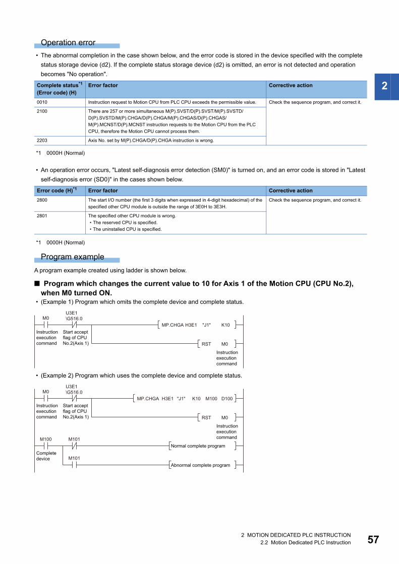
2
Operation error
• The abnormal completion in the case shown below, and the error code is stored in the device specified with the complete
status storage device (d2). If the complete status storage device (d2) is omitted, an error is not detected and operation
becomes "No operation".
*1 0000H (Normal)
• An operation error occurs, "Latest self-diagnosis error detection (SM0)" is turned on, and an error code is stored in "Latest
self-diagnosis error (SD0)" in the cases shown below.
*1 0000H (Normal)
Program example
A program example created using ladder is shown below.
■ Program which changes the current value to 10 for Axis 1 of the Motion CPU (CPU No.2), when M0 turned ON.
• (Example 1) Program which omits the complete device and complete status.
• (Example 2) Program which uses the complete device and complete status.
Complete status*1
(Error code) (H)Error factor Corrective action
0010 Instruction request to Motion CPU from PLC CPU exceeds the permissible value. Check the sequence program, and correct it.
2100 There are 257 or more simultaneous M(P).SVST/D(P).SVST/M(P).SVSTD/
D(P).SVSTD/M(P).CHGA/D(P).CHGA/M(P).CHGAS/D(P).CHGAS/
M(P).MCNST/D(P).MCNST instruction requests to the Motion CPU from the PLC
CPU, therefore the Motion CPU cannot process them.
2203 Axis No. set by M(P).CHGA/D(P).CHGA instruction is wrong.
Error code (H)*1 Error factor Corrective action
2800 The start I/O number (the first 3 digits when expressed in 4-digit hexadecimal) of the
specified other CPU module is outside the range of 3E0H to 3E3H.
Check the sequence program, and correct it.
2801 The specified other CPU module is wrong.
• The reserved CPU is specified.
• The uninstalled CPU is specified.
M0
Instructionexecutioncommand
Instructionexecutioncommand
U3E1\G516.0
Start acceptflag of CPUNo.2(Axis 1)
H3E1 K10"J1"
RST M0
MP.CHGA
MP.CHGA H3E1 K10"J1" M100 D100
M100
Completedevice
M101
M101
Normal complete program
Abnormal complete program
M0
Instructionexecutioncommand
Instructionexecutioncommand
U3E1\G516.0
Start acceptflag of CPUNo.2(Axis 1) RST M0
2 MOTION DEDICATED PLC INSTRUCTION2.2 Motion Dedicated PLC Instruction 57

58
Current value change instruction of command generation axis from the PLC CPU to the Motion CPU: M(P).CHGAS/D(P).CHGAS
M(P).CHGAS/D(P).CHGAS
■ Program
*1 An instruction should be described in each area.
■ Execution condition
Setting data
■ Description, range, setting side, data type
*1 Omission possible when both (d1) and (d2) are omitted.*2 Motion CPU cannot be set as CPU No.1 in the Multiple CPU configuration.*3 n shows the numerical value correspond to axis No. (n=1 to 64)*4 Use the methods shown below to enclose character string data depending on the programming language being used.
Ladder*1 FBD/LD*1 ST
ENO:=MP_CHGAS(EN,UnHn,s1,s2,d1,d2);
ENO:=DP_CHGAS(EN,UnHn,s1,s2,d1,d2);
ENO:=M_CHGAS(EN,UnHn,s1,s2,d1,d2);
ENO:=D_CHGAS(EN,UnHn,s1,s2,d1,d2);
Instruction Execution condition
MP.CHGAS
DP.CHGAS
M.CHGAS
D.CHGAS
Setting data Description Setting range Set by Data type Data type (label)
(UnHn) Start I/O No. (the first 3 digits when expressed in 4-digit hexadecimal) of
the target CPU*2
• CPU No.2: 3E1H
• CPU No.3: 3E2H
• CPU No.4: 3E3H
3E1H to 3E3H User 16-bit binary ANY16
(s1) Axis No. (Jn)*3 to execute the current value change of command
generation axis.
• R64MTCPU: J1 to J64
• R32MTCPU: J1 to J32
• R16MTCPU: J1 to J16
1 to 64 User Character
string*4ANYSTRING_SIN
GLE
(s2) Current value to change -2147483648 to
2147483647
User 32-bit binary ANY32
(d1)*1 Complete devices
• (d1+0): Device which make turn on for one scan at accept completion
of instruction.
• (d1+1): Device which make turn on for one scan at accept abnormal
completion of instruction. ("d1+0" also turns on at the abnormal
completion.)
System Bit ANYBIT_ARRAY
(d2)*1 Complete status storage device System Word ANY16
EN Execution condition (inputs the condition to control execution of the
instruction)
User Bit BOOL
ENO Execution result (outputs the execution result of the instruction) System Bit BOOL
Programming language Description method Description example
Ladder Enclose the character string in double quotation marks (" "). "J10"
FBD/LD Enclose the character string in single quotation marks (' '). 'J10'
ST
Command(UnHn) (s1) (s2)
Command(UnHn) (s1) (s2) (d1) (d2)
EN
UnHn
s1
ENO
d1
d2
s2
2 MOTION DEDICATED PLC INSTRUCTION2.2 Motion Dedicated PLC Instruction

2
■ Usable devices: Usable, : Usable partly
*1 Setting data (UnHn) to (d2): Index qualification possible (except constant)*2 Omission possible when both (d1) and (d2) are omitted.*3 Local devices cannot be used.
Processing details
■ Controls • The current value change of command generation axis (stopped axis) specified with (s1) is changed to the current value
specified with (s2).
• It is necessary to take an inter-lock by the start accept flag and user device of CPU buffer memory so that multiple
instructions may not be executed toward the same axis of same Motion CPU.
Refer to the start accept flag (system area) for details of the start accept flag. (Page 87 Start accept flag
(System area))
■ OperationAn outline of operation between CPUs when specifying the Axis No. (Jn) at MP.CHGAS and DP.CHGAS instruction execution
is shown below.
• MP.CHGAS instruction
Setting data*1
Internal devices (System, User)
File register Link direct device J□\□
Module access device U□\G□
Index registerZ□
Constant Others
Bit Word Bit Word Bit Word Bit Word Decimal K, Hexadecimal H
Real character string
(UnHn)
(s1)
(s2)
(d1)*2 *3 *3
(d2)*2 *3 *3
Requestdata set
ONMP.CHGAS executionSequence program
MP.CHGAS instruction
Current value change
END END
Axis start accept flag(System area)
ON
Complete device (d1+0)
ON
Status display device (d1+1)at the completion
CPU dedicated transmission(Non-fixed cycle)
1 scan
ON: Abnormal completion only
Transfer
Responsedata set
Current valuechange processing
2 MOTION DEDICATED PLC INSTRUCTION2.2 Motion Dedicated PLC Instruction 59

60
• DP.CHGAS instruction
*1 Set in [System Parameter] [Multiple CPU settings] in GX Works3
■ Setting of axis to execute the current value changeThe axis to execute the current value change being set to (s1) is set as "J + Axis No." in a character string.
The number of axes which can be set to (s1) is only 1 axis. Set "J" in a capital letter or small letter and use the axis No. set in
the command generation axis parameter as the axis No. to start. Refer to the following for command generation axis
parameter.
MELSEC iQ-R Motion controller Programming Manual (Advanced Synchronous Control)
Enclose the set character string (J + Axis No.) with double quotation marks (" ") for a ladder program, or with single quotation
marks (' ') for an FBD/ST program.
■ Start accept flag (System area)When the instruction is executed by specifying the Axis No. (Jn), the complete status of start accept flag is stored in the
address of the start accept flag in the CPU buffer memory for target CPU.
Motion CPU (s1) usable range
R64MTCPU 1 to 64
R32MTCPU 1 to 32
R16MTCPU 1 to 16
CPU buffer memory address( ) is decimal address
Description
20EH(526)
20FH(527)
210H(528)
211H(529)
The command generation axis start accept flag for 64 axes are stored corresponding to each bit.
Bits are actually set as the following:
• R64MTCPU: J1 to J64
• R32MTCPU: J1 to J32
• R16MTCPU: J1 to J16
OFF: Start accept enable
ON: Start accept disable
Sequence program
DP.CHGAS instruction
ON DP.CHGAS execution
Request data set
Current value change
END END
Axis start accept flag(System area)
ON
Complete device (d1+0)
ON
Status display device (d1+1)at the completion
CPU dedicated transmission (Fixed cycle)
Communicationcycle*1
Transfer Transfer
Current value change processing
Responsedata set
ON: Abnormal completion only
1 scan
20EH(526) address
20FH(527) address
J16
J32
b15
J1
J17
b0
J2
J18
210H(528) address J48 J33J34
211H(529) address J64 J49J50
b1b2
2 MOTION DEDICATED PLC INSTRUCTION2.2 Motion Dedicated PLC Instruction

2
Operation error
• The abnormal completion in the case shown below, and the error code is stored in the device specified with the complete
status storage device (d2). If the complete status storage device (d2) is omitted, an error is not detected and operation
becomes "No operation".
*1 0000H (Normal)
• An operation error occurs, "Latest self-diagnosis error detection (SM0)" is turned on, and an error code is stored in "Latest
self-diagnosis error (SD0)" in the cases shown below.
*1 0000H (Normal)
Program example
A program example created using ladder is shown below.
■ Program which changes the current value to 10 for Axis 1 of the Motion CPU (CPU No.2), when M0 turned ON.
• (Example 1) Program which omits the complete device and complete status.
• (Example 2) Program which uses complete device and complete status.
Complete status*1
(Error code) (H)Error factor Corrective action
0010 Instruction request to Motion CPU from PLC CPU exceeds the permissible value. Check the sequence program, and correct it.
2100 There are 257 or more simultaneous M(P).SVST/D(P).SVST/M(P).SVSTD/
D(P).SVSTD/M(P).CHGA/D(P).CHGA/M(P).CHGAS/D(P).CHGAS/
M(P).MCNST/D(P).MCNST instruction requests to the Motion CPU from the PLC
CPU, therefore the Motion CPU cannot process them.
2207 Axis No. set by M(P).CHGAS/D(P).CHGAS instruction is wrong.
Error code (H)*1 Error factor Corrective action
2800 The start I/O number (the first 3 digits when expressed in 4-digit hexadecimal) of the
specified other CPU module is outside the range of 3E0H to 3E3H.
Check the sequence program, and correct it.
2801 The specified other CPU module is wrong.
• The reserved CPU is specified.
• The uninstalled CPU is specified.
M0
Instructionexecutioncommand
Instructionexecutioncommand
U3E1\G526.0
Start acceptflag of CPUNo.2(Axis 1)
MP.CHGAS H3E1 K10"J1"
RST M0
MP.CHGAS H3E1 K10"J1" M100 D100
M100
Completedevice
M101
M101
Normal complete program
Abnormal complete program
M0
Instructionexecutioncommand
Instructionexecutioncommand
U3E1\G526.0
Start acceptflag of CPUNo.2(Axis 1) RST M0
2 MOTION DEDICATED PLC INSTRUCTION2.2 Motion Dedicated PLC Instruction 61
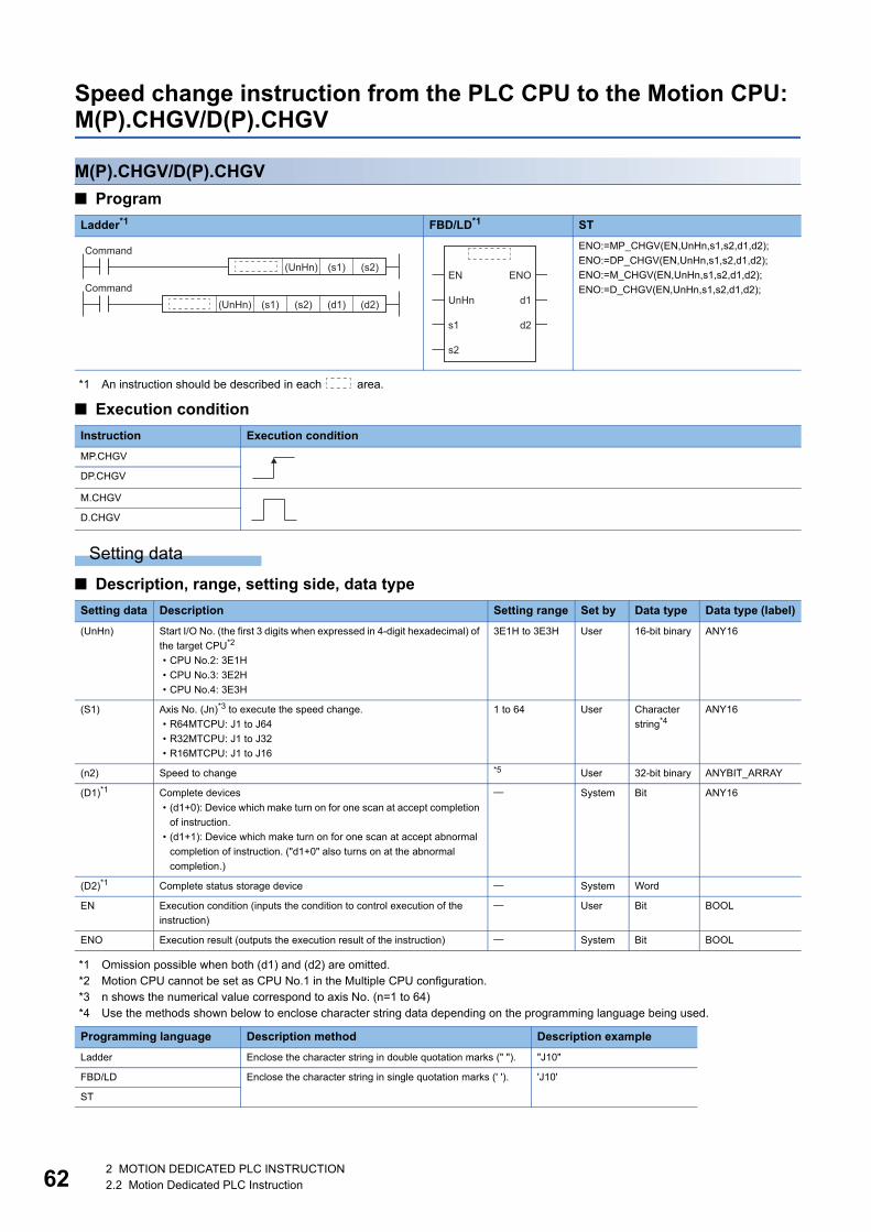
62
Speed change instruction from the PLC CPU to the Motion CPU: M(P).CHGV/D(P).CHGV
M(P).CHGV/D(P).CHGV
■ Program
*1 An instruction should be described in each area.
■ Execution condition
Setting data
■ Description, range, setting side, data type
*1 Omission possible when both (d1) and (d2) are omitted.*2 Motion CPU cannot be set as CPU No.1 in the Multiple CPU configuration.*3 n shows the numerical value correspond to axis No. (n=1 to 64)*4 Use the methods shown below to enclose character string data depending on the programming language being used.
Ladder*1 FBD/LD*1 ST
ENO:=MP_CHGV(EN,UnHn,s1,s2,d1,d2);
ENO:=DP_CHGV(EN,UnHn,s1,s2,d1,d2);
ENO:=M_CHGV(EN,UnHn,s1,s2,d1,d2);
ENO:=D_CHGV(EN,UnHn,s1,s2,d1,d2);
Instruction Execution condition
MP.CHGV
DP.CHGV
M.CHGV
D.CHGV
Setting data Description Setting range Set by Data type Data type (label)
(UnHn) Start I/O No. (the first 3 digits when expressed in 4-digit hexadecimal) of
the target CPU*2
• CPU No.2: 3E1H
• CPU No.3: 3E2H
• CPU No.4: 3E3H
3E1H to 3E3H User 16-bit binary ANY16
(S1) Axis No. (Jn)*3 to execute the speed change.
• R64MTCPU: J1 to J64
• R32MTCPU: J1 to J32
• R16MTCPU: J1 to J16
1 to 64 User Character
string*4ANY16
(n2) Speed to change *5 User 32-bit binary ANYBIT_ARRAY
(D1)*1 Complete devices
• (d1+0): Device which make turn on for one scan at accept completion
of instruction.
• (d1+1): Device which make turn on for one scan at accept abnormal
completion of instruction. ("d1+0" also turns on at the abnormal
completion.)
System Bit ANY16
(D2)*1 Complete status storage device System Word
EN Execution condition (inputs the condition to control execution of the
instruction)
User Bit BOOL
ENO Execution result (outputs the execution result of the instruction) System Bit BOOL
Programming language Description method Description example
Ladder Enclose the character string in double quotation marks (" "). "J10"
FBD/LD Enclose the character string in single quotation marks (' '). 'J10'
ST
Command(UnHn) (s1) (s2)
Command(UnHn) (s1) (s2) (d1) (d2)
EN
UnHn
s1
ENO
d1
d2
s2
2 MOTION DEDICATED PLC INSTRUCTION2.2 Motion Dedicated PLC Instruction

2
*5 The setting range of each setting unit for (s2) is shown below.
*6 When the "speed control 10 multiplier setting for degree axis" is set to "valid", the setting range is -2147483647 to 2147483647 (10-
2[degree/min]).
■ Usable devices: Usable, : Usable partly
*1 Setting data (UnHn) to (d2): Index qualification possible (except constant)*2 Omission possible when both (d1) and (d2) are omitted.*3 Local devices cannot be used.
Processing details
■ Controls • The speed of axis specified with (s1) is changed to the speed specified with (s2) during positioning or JOG operating.
• There is not an interlock signal on the buffer memory during speed change. When the multiple instructions are executed
toward the same axis of same Motion CPU, the speed is changed to specified value by last instruction.
• Acceleration/deceleration time at speed change can be changed by setting the acceleration/deceleration time change
parameter of the axis specified with (s1). Refer to the following for acceleration/deceleration time change parameter and
acceleration/deceleration time change function.
MELSEC iQ-R Motion controller Programming Manual (Positioning Control)
■ OperationAn outline of operation between CPUs at the MP.CHGV and DP.CHGV instruction execution is shown below.
• MP.CHGV instruction
Unit (s2) usable range
mm -600000000 to 600000000 (10-2[mm/min])
inch -600000000 to 600000000 (10-3[inch/min])
degree -2147483647 to 2147483647 (10-3[degree/min])*6
pulse -2147483647 to 2147483647[pulse/s]
Setting data*1
Internal devices (System, User)
File register Link direct device J□\□
Module access device U□\G□
Index registerZ□
Constant Others
Bit Word Bit Word Bit Word Bit Word Decimal K, Hexadecimal H
Real character string
(UnHn)
(s1)
(s2)
(d1)*2 *3 *3
(d2)*2 *3 *3
Sequence program
Speed change
END END
Complete device (d1+0)
ON
Status display device (d1+1)at the completion
CPU dedicated transmission(Non-fixed cycle)
1 scan
Transfer
Speed change processing
Responsedata set
ON: Abnormal completion only
Request data set
ONMP.CHGV execution
MP.CHGV instruction
2 MOTION DEDICATED PLC INSTRUCTION2.2 Motion Dedicated PLC Instruction 63

64
• DP.CHGV instruction
*1 Set in [System Parameter] [Multiple CPU settings] in GX Works3
■ Setting of axis to execute the speed changeThe axis to execute the speed change being set to (s1) is set as "J + axis No." in a character string.
The number of axes which can be set to (s1) is only 1 axis. Set "J" in a capital letter or small letter and use the axis No. set in
the servo network setting as the axis No. to start. Refer to the following for servo network settings.
MELSEC iQ-R Motion controller Programming Manual (Common)
Enclose the set character string (J + Axis No.) with double quotation marks (" ") for a ladder program, or with single quotation
marks (' ') for an FBD/ST program.
Operation error
• The abnormal completion in the case shown below, and the error code is stored in the device specified with the complete
status storage device (d2). If the complete status storage device (d2) is omitted, an error is not detected and operation
becomes "No operation".
*1 0000H (Normal)
• An operation error occurs, "Latest self-diagnosis error detection (SM0)" is turned on, and an error code is stored in "Latest
self-diagnosis error (SD0)" in the cases shown below.
*1 0000H (Normal)
Motion CPU (s1) usable range
R64MTCPU 1 to 64
R32MTCPU 1 to 32
R16MTCPU 1 to 16
Complete status*1
(Error code) (H)Error factor Corrective action
0010 Instruction request to Motion CPU from PLC CPU exceeds the permissible value. Check the sequence program, and correct it.
2204 Axis No. set by M(P).CHGV/D(P).CHGV instruction is wrong.
Error code (H)*1 Error factor Corrective action
2800 The start I/O number (the first 3 digits when expressed in 4-digit hexadecimal) of the
specified other CPU module is outside the range of 3E0H to 3E3H.
Check the sequence program, and correct it.
2801 The specified other CPU module is wrong.
• The reserved CPU is specified.
• The uninstalled CPU is specified.
Sequence program
DP.CHGV instruction
ON DP.CHGV execution
Request data set
Speed change
END END
Complete device (d1+0)
ON
Status display device (d1+1)at the completion
CPU dedicated transmission(Fixed cycle)
Communicationcycle*1
1 scan
Transfer Transfer
Speed change processing
Responsedata set
ON: Abnormal completion only
2 MOTION DEDICATED PLC INSTRUCTION2.2 Motion Dedicated PLC Instruction

2
Program example
A program example created using ladder is shown below.
■ Program which changes the positioning speed to 20000 for Axis 1 of the Motion CPU (CPU No.2), when M0 turned ON.
• (Example 1) Program which omits the complete device and complete status.
• (Example 2) Program which uses the complete device and complete status.
M0
Instructionexecutioncommand
Instructionexecutioncommand
MP.CHGV H3E1 K20000"J1"
RST M0
MP.CHGV H3E1 K20000"J1" M100 D100
M100
Completedevice
M101
M101
Normal complete program
Abnormal complete program
M0
Instructionexecutioncommand
Instructionexecutioncommand
RST M0
2 MOTION DEDICATED PLC INSTRUCTION2.2 Motion Dedicated PLC Instruction 65

66
■ Program which changes the positioning speed to 200000 for Axis 1 of the Motion CPU (CPU No.2), when M0 that sets Axis No. as indirect setting method turned ON, and then changes the positioning speed to 50000 for Axis 2, M1 turned ON
M0
Axis No.offset
MOVP K0 Z0
Axis No.2for indirectsetting
$MOVP "J2" D2
SM402
Only 1scan ONafter start
Axis No.1for indirectsetting
$MOVP "J1" D0
MP.CHGV H3E1 D4@W0 M100 D100M11
Axis 1CHGVinstructionexecutioncommand
Axis No.indirectsettingdeviceaddresssetting
Axis 2CHGVinstructionexecutioncommand
M1
Axis 2 speedchangecommand
Axis 2CHGVinstructionexecutioncommand
M10
Axis 1CHGVinstructionexecutioncommand
M10
Axis 1CHGVinstructionexecutioncommand
Axis 2speedchangecommand
ADRSET D0Z0 W0
Axis No.offset
MOVP K2 Z0
RST M10
RST M11
Axis 2 CHGVinstructionexecutioncommand
SET M11
Changespeedsetting
DMOVP K50000 D4
RST M1
Axis 1speedchangecommand
Axis 1speedchangecommand
Axis 1CHGVinstructionexecutioncommand
SET M10
Changespeedsetting
DMOVP K200000 D4
RST M0
2 MOTION DEDICATED PLC INSTRUCTION2.2 Motion Dedicated PLC Instruction
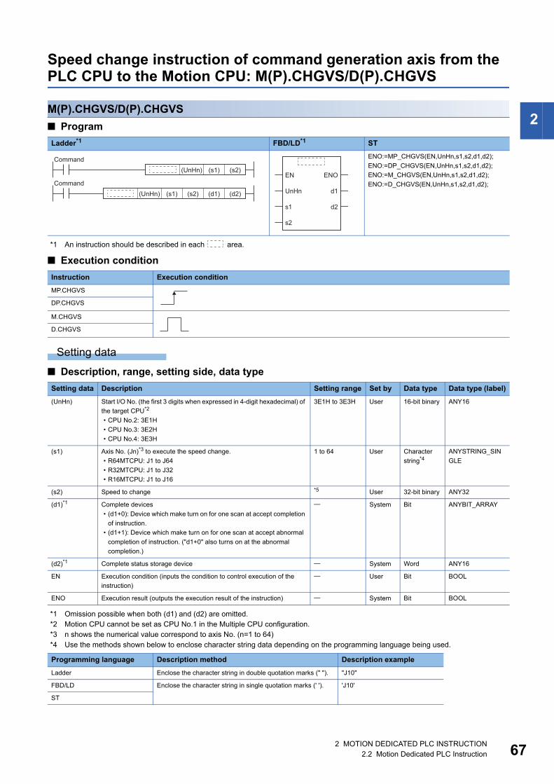
2
Speed change instruction of command generation axis from the PLC CPU to the Motion CPU: M(P).CHGVS/D(P).CHGVS
M(P).CHGVS/D(P).CHGVS
■ Program
*1 An instruction should be described in each area.
■ Execution condition
Setting data
■ Description, range, setting side, data type
*1 Omission possible when both (d1) and (d2) are omitted.*2 Motion CPU cannot be set as CPU No.1 in the Multiple CPU configuration.*3 n shows the numerical value correspond to axis No. (n=1 to 64)*4 Use the methods shown below to enclose character string data depending on the programming language being used.
Ladder*1 FBD/LD*1 ST
ENO:=MP_CHGVS(EN,UnHn,s1,s2,d1,d2);
ENO:=DP_CHGVS(EN,UnHn,s1,s2,d1,d2);
ENO:=M_CHGVS(EN,UnHn,s1,s2,d1,d2);
ENO:=D_CHGVS(EN,UnHn,s1,s2,d1,d2);
Instruction Execution condition
MP.CHGVS
DP.CHGVS
M.CHGVS
D.CHGVS
Setting data Description Setting range Set by Data type Data type (label)
(UnHn) Start I/O No. (the first 3 digits when expressed in 4-digit hexadecimal) of
the target CPU*2
• CPU No.2: 3E1H
• CPU No.3: 3E2H
• CPU No.4: 3E3H
3E1H to 3E3H User 16-bit binary ANY16
(s1) Axis No. (Jn)*3 to execute the speed change.
• R64MTCPU: J1 to J64
• R32MTCPU: J1 to J32
• R16MTCPU: J1 to J16
1 to 64 User Character
string*4ANYSTRING_SIN
GLE
(s2) Speed to change *5 User 32-bit binary ANY32
(d1)*1 Complete devices
• (d1+0): Device which make turn on for one scan at accept completion
of instruction.
• (d1+1): Device which make turn on for one scan at accept abnormal
completion of instruction. ("d1+0" also turns on at the abnormal
completion.)
System Bit ANYBIT_ARRAY
(d2)*1 Complete status storage device System Word ANY16
EN Execution condition (inputs the condition to control execution of the
instruction)
User Bit BOOL
ENO Execution result (outputs the execution result of the instruction) System Bit BOOL
Programming language Description method Description example
Ladder Enclose the character string in double quotation marks (" "). "J10"
FBD/LD Enclose the character string in single quotation marks (' '). 'J10'
ST
Command(UnHn) (s1) (s2)
Command(UnHn) (s1) (s2) (d1) (d2)
EN
UnHn
s1
ENO
d1
d2
s2
2 MOTION DEDICATED PLC INSTRUCTION2.2 Motion Dedicated PLC Instruction 67

68
*5 The setting range of each setting unit for (s2) is shown below.
*6 When the "speed control 10 multiplier setting for degree axis" is set to "valid", the setting range is -2147483647 to 2147483647 (10-
2[degree/min]).
■ Usable devices: Usable, : Usable partly
*1 Setting data (UnHn) to (d2): Index qualification possible (except constant)*2 Omission possible when both (d1) and (d2) are omitted.*3 Local devices cannot be used.
Processing details
■ Controls • The speed of command generation axis specified with (s1) is changed to the speed specified with (s2) during positioning or
JOG operating.
• There is not an interlock signal on the buffer memory during speed change. When the multiple instructions are executed
toward the same axis of same Motion CPU, the speed is changed to specified value by last instruction.
• Acceleration/deceleration time at speed change can be changed by setting the acceleration/deceleration time change
parameter of the axis specified with (s1). Refer to the following for acceleration/deceleration time change parameter.
MELSEC iQ-R Motion controller Programming Manual (Advanced Synchronous Control)Refer to the following for
acceleration/deceleration time change function.
MELSEC iQ-R Motion controller Programming Manual (Positioning Control)
■ OperationAn outline of operation between CPUs at the MP.CHGVS and DP.CHGVS instruction execution is shown below.
• MP.CHGVS instruction
Unit (s2) usable range
mm -600000000 to 600000000 (10-2[mm/min])
inch -600000000 to 600000000 (10-3[inch/min])
degree -2147483647 to 2147483647 (10-3[degree/min])*6
pulse -2147483647 to 2147483647[pulse/s]
Setting data*1
Internal devices (System, User)
File register Link direct device J□\□
Module access device U□\G□
Index registerZ□
Constant Others
Bit Word Bit Word Bit Word Bit Word Decimal K, Hexadecimal H
Real character string
(UnHn)
(s1)
(s2)
(d1)*2 *3 *3
(d2)*2 *3 *3
Sequence program
Speed change
END END
Complete device (d1+0)
ON
Status display device (d1+1)at the completion
CPU dedicated transmission(Non-fixed cycle)
1 scan
Transfer
Speed change processing
Responsedata set
ON: Abnormal completion only
Request data set
ONMP.CHGVS execution
MP.CHGVS instruction
2 MOTION DEDICATED PLC INSTRUCTION2.2 Motion Dedicated PLC Instruction

2
• DP.CHGVS instruction
*1 Set in [System Parameter] [Multiple CPU settings] in GX Works3
■ Setting of axis to execute the speed changeThe axis to execute the speed change being set to (s1) is set as "J + axis No." in a character string.
The number of axes which can be set to (s1) is only 1 axis. Set "J" in a capital letter or small letter and use the axis No. set in
the command generation axis parameter as the axis No. to start. Refer to the following for command generation axis
parameter.
MELSEC iQ-R Motion controller Programming Manual (Advanced Synchronous Control)
Enclose the set character string (J + Axis No.) with double quotation marks (" ") for a ladder program, or with single quotation
marks (' ') for an FBD/ST program.
Operation error
• The abnormal completion in the case shown below, and the error code is stored in the device specified with the complete
status storage device (d2). If the complete status storage device (d2) is omitted, an error is not detected and operation
becomes "No operation".
*1 0000H (Normal)
• An operation error occurs, "Latest self-diagnosis error detection (SM0)" is turned on, and an error code is stored in "Latest
self-diagnosis error (SD0)" in the cases shown below.
*1 0000H (Normal)
Motion CPU (s1) usable range
R64MTCPU 1 to 64
R32MTCPU 1 to 32
R16MTCPU 1 to 16
Complete status*1
(Error code) (H)Error factor Corrective action
0010 Instruction request to Motion CPU from PLC CPU exceeds the permissible value. Check the sequence program, and correct it.
2208 Axis No. set by M(P).CHGVS/D(P).CHGVS instruction is wrong.
Error code (H)*1 Error factor Corrective action
2800 The start I/O number (the first 3 digits when expressed in 4-digit hexadecimal) of the
specified other CPU module is outside the range of 3E0H to 3E3H.
Check the sequence program, and correct it.
2801 The specified other CPU module is wrong.
• The reserved CPU is specified.
• The uninstalled CPU is specified.
Sequence program
DP.CHGVS instruction
ON DP.CHGVS execution
Request data set
Speed change
END END
Complete device (d1+0)
ON
Status display device (d1+1)at the completion
CPU dedicated transmission(Fixed cycle)
Communicationcycle*1
1 scan
Transfer Transfer
Speed change processing
Responsedata set
ON: Abnormal completion only
2 MOTION DEDICATED PLC INSTRUCTION2.2 Motion Dedicated PLC Instruction 69

70
Program example
A program example created using ladder is shown below.
■ Program which changes the positioning speed of 20000 for Axis 1 of the Motion CPU (CPU No.2), when M0 turned ON
• (Example 1) Program which omits the complete device and complete status.
• (Example 2) Program which uses the complete device and complete status.
M0
Instructionexecutioncommand
Instructionexecutioncommand
MP.CHGVSH3E1 K20000"J1"
RST M0
MP.CHGVSH3E1 K20000"J1" M100 D100
Normal complete programM100
Completedevice
M101
M101Abnormal complete program
M0
Instructionexecutioncommand
Instructionexecutioncommand
RST M0
2 MOTION DEDICATED PLC INSTRUCTION2.2 Motion Dedicated PLC Instruction

2
■ Program which changes the positioning speed to 200000 for Axis 1 of the Motion CPU (CPU No.2), when M0 that sets Axis No. as indirect setting method turned ON, and then changes the positioning speed to 50000 for Axis 2, when M1 turned ON
M0
Axis No.offset
MOVP K0 Z0
Axis No.2for indirectsetting
$MOVP "J2" D2
SM402
Only 1scan ONafter start
Axis No.1for indirectsetting
$MOVP "J1" D0
MP.CHGVS H3E1 D4@W0 M100 D100M11
Axis 1CHGVSinstructionexecutioncommand
Axis No.indirectsettingdeviceaddresssetting
Axis 2CHGVSinstructionexecutioncommand
M1
Axis 2 speedchangecommand
Axis 2CHGVSinstructionexecutioncommand
M10
Axis 1CHGVSinstructionexecutioncommand
M10
Axis 1CHGVSinstructionexecutioncommand
Axis 2speedchangecommand
ADRSET D0Z0 W0
Axis No.offset
MOVP K2 Z0
RST M10
RST M11
Axis 2 CHGVSinstructionexecutioncommand
SET M11
Changespeedsetting
DMOVP K50000 D4
RST M1
Axis 1speedchangecommand
Axis 1speedchangecommand
Axis 1CHGVSinstructionexecutioncommand
SET M10
Changespeedsetting
DMOVP K200000 D4
RST M0
2 MOTION DEDICATED PLC INSTRUCTION2.2 Motion Dedicated PLC Instruction 71
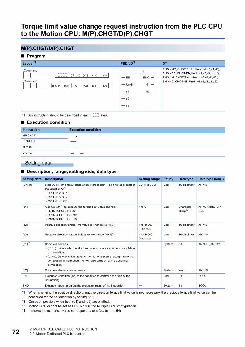
72
Torque limit value change request instruction from the PLC CPU to the Motion CPU: M(P).CHGT/D(P).CHGT
M(P).CHGT/D(P).CHGT
■ Program
*1 An instruction should be described in each area.
■ Execution condition
Setting data
■ Description, range, setting side, data type
*1 When changing the positive direction/negative direction torque limit value is not necessary, the previous torque limit value can be continued for the set direction by setting "-1".
*2 Omission possible when both (d1) and (d2) are omitted.*3 Motion CPU cannot be set as CPU No.1 in the Multiple CPU configuration.*4 n shows the numerical value correspond to axis No. (n=1 to 64)
Ladder*1 FBD/LD*1 ST
ENO:=MP_CHGT(EN,UnHn,s1,s2,s3,d1,d2);
ENO:=DP_CHGT(EN,UnHn,s1,s2,s3,d1,d2);
ENO:=M_CHGT(EN,UnHn,s1,s2,s3,d1,d2);
ENO:=D_CHGT(EN,UnHn,s1,s2,s3,d1,d2);
Instruction Execution condition
MP.CHGT
DP.CHGT
M.CHGT
D.CHGT
Setting data Description Setting range Set by Data type Data type (label)
(UnHn) Start I/O No. (the first 3 digits when expressed in 4-digit hexadecimal) of
the target CPU*3
• CPU No.2: 3E1H
• CPU No.3: 3E2H
• CPU No.4: 3E3H
3E1H to 3E3H User 16-bit binary ANY16
(s1) Axis No. (Jn)*4 to execute the torque limit value change.
• R64MTCPU: J1 to J64
• R32MTCPU: J1 to J32
• R16MTCPU: J1 to J16
1 to 64 User Character
string*5ANYSTRING_SIN
GLE
(s2)*1 Positive direction torque limit value to change (0.1[%]) 1 to 10000
(0.1[%])
User 16-bit binary ANY16
(s3)*1 Negative direction torque limit value to change (0.1[%]) 1 to 10000
(0.1[%])
User 16-bit binary ANY16
(d1)*2 Complete devices
• (d1+0): Device which make turn on for one scan at accept completion
of instruction.
• (d1+1): Device which make turn on for one scan at accept abnormal
completion of instruction. ("d1+0" also turns on at the abnormal
completion.)
System Bit ANYBIT_ARRAY
(d2)*2 Complete status storage device System Word ANY16
EN Execution condition (inputs the condition to control execution of the
instruction)
User Bit BOOL
ENO Execution result (outputs the execution result of the instruction) System Bit BOOL
Command(UnHn) (s1) (s2) (s3)
Command(UnHn) (s1) (s2) (s3) (d1) (d2)
EN
UnHn
s1
ENO
d1
d2
s2
s3
2 MOTION DEDICATED PLC INSTRUCTION2.2 Motion Dedicated PLC Instruction

2
*5 Use the methods shown below to enclose character string data depending on the programming language being used.
■ Usable devices: Usable, : Usable partly
*1 Setting data (UnHn) to (d2): Index qualification possible (except constant)*2 Omission possible when both (d1) and (d2) are omitted.*3 Local devices cannot be used.
Processing details
■ Controls • The torque limit value of axis specified with (s1) is changed to the positive direction torque limit value specified with (s2)
and negative direction torque limit value specified with (s3) regardless of while being operating or stopping.
• There is not an interlock signal for status of axis torque change. When the multiple instructions are executed toward the
same axis of same Motion CPU, the torque is changed to specified value by last instruction.
• Refer to the following for relation between torque limit value specified with servo program and torque limit value change
instruction.
MELSEC iQ-R Motion controller Programming Manual (Positioning Control)
■ OperationAn outline of operation between CPUs at the MP.CHGT and DP.CHGT instruction execution is shown below.
• MP.CHGT instruction
Programming language Description method Description example
Ladder Enclose the character string in double quotation marks (" "). "J10"
FBD/LD Enclose the character string in single quotation marks (' '). 'J10'
ST
Setting data*1
Internal devices (System, User)
File register Link direct device J□\□
Module access device U□\G□
Index registerZ□
Constant Others
Bit Word Bit Word Bit Word Bit Word Decimal K, Hexadecimal H
Real character string
(UnHn)
(s1)
(s2)
(s3)
(d1)*2 *3 *3
(d2)*2 *3 *3
Sequence program
Torque limit value change(Positive direction/Negative direction)
END END
Complete device (d1+0)
ON
Status display device (d1+1)at the completion
CPU dedicated transmission(Non-fixed cycle)
1 scan
Transfer
Responsedata set
ON: Abnormal completion only
Request data set
ONMP.CHGT execution
MP.CHGT instruction
Torque limit valuechange processing
2 MOTION DEDICATED PLC INSTRUCTION2.2 Motion Dedicated PLC Instruction 73

74
• DP.CHGT instruction
*1 Set in [System Parameter] [Multiple CPU settings] in GX Works3
■ Setting of axis to execute the torque limit value changeThe axis to execute the torque limit change being set to (s1) is set as "J + axis No." in a character string.
The number of axes which can be set to (s1) is only 1 axis. Set "J" in a capital letter or small letter and use the axis No. set in
the servo network setting as the axis No. to start. Refer to the following for servo network settings.
MELSEC iQ-R Motion controller Programming Manual (Common)
Enclose the set character string (J + Axis No.) with double quotation marks (" ") for a ladder program, or with single quotation
marks (' ') for an FBD/ST program.
Operation error
• The abnormal completion in the case shown below, and the error code is stored in the device specified with the complete
status storage device (d2). If the complete status storage device (d2) is omitted, an error is not detected and operation
becomes "No operation".
*1 0000H (Normal)
• An operation error occurs, "Latest self-diagnosis error detection (SM0)" is turned on, and an error code is stored in "Latest
self-diagnosis error (SD0)" in the cases shown below.
*1 0000H (Normal)
Motion CPU (s1) usable range
R64MTCPU 1 to 64
R32MTCPU 1 to 32
R16MTCPU 1 to 16
Complete status*1
(Error code) (H)Error factor Corrective action
0010 Instruction request to Motion CPU from PLC CPU exceeds the permissible value. Check the sequence program, and correct it.
2205 Axis No. set by M(P).CHGT/D(P).CHGT instruction is wrong.
Error code (H)*1 Error factor Corrective action
2800 The start I/O number (the first 3 digits when expressed in 4-digit hexadecimal) of the
specified other CPU module is outside the range of 3E0H to 3E3H.
Check the sequence program, and correct it.
2801 The specified other CPU module is wrong.
• The reserved CPU is specified.
• The uninstalled CPU is specified.
Sequence program
DP.CHGT instruction
ON DP.CHGT execution
Request data set
Torque limit value change(Positive direction/Negative direction)
END END
Complete device (d1+0)
ON
Status display device (d1+1)at the completion
CPU dedicated transmission(Fixed cycle)
Communicationcycle*1
1 scan
Transfer Transfer
Responsedata set
ON: Abnormal completion only
Torque limit valuechange processing
2 MOTION DEDICATED PLC INSTRUCTION2.2 Motion Dedicated PLC Instruction

2
Program example
A program example created using ladder is shown below.
■ Program which changes the positive torque limit value to 10.0[%] and negative torque limit value to 20.0[%] for Axis 1 of the Motion CPU (CPU No.2), when M0 turned ON
• (Example 1) Program which omits the complete device and complete status.
• (Example 2) Program which uses the complete device and complete status.
M0
Instructionexecutioncommand
Instructionexecutioncommand
MP.CHGT H3E1 "J1" K100 K200
RST M0
MP.CHGT H3E1 K200K100"J1" M100 D100
Normal complete programM100
Completedevice
M101
M101Abnormal complete program
M0
Instructionexecutioncommand
Instructionexecutioncommand
RST M0
2 MOTION DEDICATED PLC INSTRUCTION2.2 Motion Dedicated PLC Instruction 75

76
Machine program operation start request from the PLC CPU to the Motion CPU: M(P).MCNST/D(P).MCNST
M(P).MCNST/D(P).MCNST
■ Program
*1 An instruction should be described in each area.
■ Execution condition
Setting data
■ Description, range, setting side, data type
*1 Motion CPU cannot be set as CPU No.1 in the Multiple CPU configuration.
Ladder*1 FBD/LD*1 ST
ENO:=MP_MCNST(EN,UnHn,s1,s2,d1);
ENO:=DP_MCNST(EN,UnHn,s1,s2,d1);
ENO:=M_MCNST(EN,UnHn,s1,s2,d1);
ENO:=D_MCNST(EN,UnHn,s1,s2,d1);
Instruction Execution condition
MP.MCNST
DP.MCNST
M.MCNST
D.MCNST
Setting data Description Setting range Set by Data type Data type (label)
(UnHn) Start I/O No. (the first 3 digits when expressed in 4-digit hexadecimal) of
the target CPU*1
• CPU No.2: 3E1H
• CPU No.3: 3E2H
• CPU No.4: 3E3H
3E1H to 3E3H User 16-bit binary ANY16
(s1) First device of the self CPU where the control data is stored. Page 77
Control data
User Word ANY16
(s2) First device of the self CPU where the machine positioning data area is
stored.
Page 77
Machine
positioning data
area
User Word ANY16
(d1) Complete devices
• (d1+0): Device which make turn on for one scan at accept completion
of instruction.
• (d1+1): Device which make turn on for one scan at accept abnormal
completion of instruction. ("d1+0" also turns on at the abnormal
completion.)
System Bit ANYBIT_ARRAY
EN Execution condition (inputs the condition to control execution of the
instruction)
User Bit BOOL
ENO Execution result (outputs the execution result of the instruction) System Bit BOOL
Command(UnHn) (s1) (s2) (d1)
EN
UnHn
s1
ENO
d1
s2
2 MOTION DEDICATED PLC INSTRUCTION2.2 Motion Dedicated PLC Instruction

2
■ Usable devices: Usable, : Usable partly
*1 Setting data (UnHn) to (d1): Index qualification possible (except constant)*2 Local devices cannot be used.
■ Control data
■ Machine positioning data areaRefer to the following for the machine positioning data area.
MELSEC iQ-R Motion Controller Programming Manual (Machine Control)
Processing details
■ Controls • Request a machine program operation start to the Motion CPU from the data stored in the machine positioning data area of
the device of the self CPU specified with (s2) and after.
• It is necessary to take an inter-lock by the start accept flag of CPU buffer memory and user device so that multiple
instructions may not be executed toward the same axis of the same Motion CPU No.
Refer to the start accept flag (system area) for details of the start accept flag. (Page 87 Start accept flag
(System area))
■ OperationAn outline of operation between CPUs at the MP.MCNST and DP.MCNST instruction execution is shown below.
• MP.MCNST instruction
*1 Set in [Motion CPU Common parameter] [Basic Setting]
Setting data*1
Internal devices (System, User)
File register Link direct device J□\□
Module access device U□\G□
Index registerZ□
Constant Others
Bit Word Bit Word Bit Word Bit Word Decimal K, Hexadecimal H
Real character string
(UnHn)
(s1) *2 *2
(s2)
(d1) *2 *2
Device (s1) Item Setting data Setting range Set by
+0 Complete status The status at the instruction completion is stored.
0: No error (Normal completion)
Except 0: Error code
System
+1 Number of machine
positioning data points
Set the size of the machine positioning data area in units of words. 78 to 5444 User
Sequence program
MP.MCNST instructionRequestdata set
Machine operationprogram
END END
Axis start accept flag(System area)
ON
Complete device (d1+0)
ON
Status display device (d1+1)at the completion
CPU dedicated transmission(Non-fixed cycle)
ON MP.MCNSTexecution
Operation cycle*1
1 scan
Transfer
Responsedata set
ON: Abnormal completion only
Machine operation program executed processing
2 MOTION DEDICATED PLC INSTRUCTION2.2 Motion Dedicated PLC Instruction 77

78
• DP.MCNST instruction
*1 Set in [System Parameter] [Multiple CPU settings] in GX Works3*2 Set in [Motion CPU Common parameter] [Basic Setting]
■ Start accept flag (System area)The complete status of start accept flag is stored in the address of start accept flag in the CPU buffer memory for target CPU.
Operation error
• The abnormal completion in the case shown below, and the error code is stored in the device specified with the complete
status storage device (s1+0).
*1 0000H (Normal)
CPU buffer memory address( ) is decimal address
Description
204H(516)
205H(517)
206H(518)
207H(519)
The start accept flag for 64 axes are stored corresponding to each bit.
Bits are actually set as the following:
• R64MTCPU: J1 to J64
• R32MTCPU: J1 to J32
• R16MTCPU: J1 to J16
OFF: Start accept enable
ON: Start accept disable
Complete status*1
(Error code) (H)Error factor Corrective action
0010 Instruction request to Motion CPU from PLC CPU exceeds the permissible value. Check the sequence program, and correct it.
2100 There are 257 or more simultaneous M(P).SVST/D(P).SVST/M(P).SVSTD/
D(P).SVSTD/M(P).CHGA/D(P).CHGA/M(P).CHGAS/D(P).CHGAS/
M(P).MCNST/D(P).MCNST instruction requests to the Motion CPU from the PLC
CPU, therefore the Motion CPU cannot process them.
2240 Instruction area for M(P).MCNST/D(P).MCNST instructions is not enough. (There are
9 or more instructions in operation by the Motion dedicated PLC instructions
(M(P).MCNST/D(P).MCNST) and Motion dedicated function (MCNST))
2241 The machine positioning data area setting for M(P).MCNST/D(P).MCNST instruction
is wrong.
2242 The control method for each point of the M(P).MCNST/D(P).MCNST instruction is
wrong. (Includes when the control method for every point is NOP only)
2243 Machine No. set by M(P).MCNST/D(P).MCNST instruction is wrong.
ON DP.MCNST execution
Requestdata set
END END
ON
ON
1 scan
Transfer Transfer
Responsedata set
ON: Abnormal completion only
Sequence program
DP.MCNST instruction
Machine operationprogram
Axis start accept flag(CPU buffer memory)
Complete device (d1+0)
Status display device (d1+1)at the completion
CPU dedicated transmission(Fixed cycle)
executed processingMachine operation program
Communication
Operation
cycle*1
cycle*2
204H(516) address
205H(517) address
J16
J32
b15
J1
J17
b0
J2
J18
206H(518) address J48 J33J34
207H(519) address J64 J49J50
b1b2
2 MOTION DEDICATED PLC INSTRUCTION2.2 Motion Dedicated PLC Instruction

2
• An operation error occurs, "Latest self-diagnosis error detection (SM0)" is turned on, and an error code is stored in "Latest
self-diagnosis error (SD0)" in the cases shown below.
*1 0000H (Normal)
Program example
A program example created using ladder is shown below.
■ Program for machine program start request which performs linear interpolation to positioning point P100 at a command speed of 10000 for the machine 1 that consists of axis 1 and axis 2, by the Motion CPU (CPU No.2), when M0 turned ON
Error code (H)*1 Error factor Corrective action
2800 The start I/O number (the first 3 digits when expressed in 4-digit hexadecimal) of the
specified other CPU module is outside the range of 3E0H to 3E3H.
Check the sequence program, and correct it.
2801 The specified other CPU module is wrong.
• The reserved CPU is specified.
• The uninstalled CPU is specified.
2802 The other CPU module does not support M(P).MCNST/D(P).MCNST instructions.
MOVP K1 D2000 Number of positioning points (1)
Machine No. (1)
Positioning data items setting(all disabled)
Positioning data items setting value(For 32 words)(Not used (0))
Specify positioning point(world coordinate system)
Command speed (10000)
Point block data (P100)
Auxiliary/central point block data(Not used (0))
Radius (Not used (0))
Expansion point items setting(all disabled)
Machine operation data area points(78 points (D2000 to D2077))
Start machine program operationMP.MCNSTH3E1 D1000 D2000 M100
RST M0
MOVP K1 D2001
DMOVPK0 D2002
FMOVPK0 D2004 K32
MOVP K0 D2037
Control method (linear interpolation (ABS))MOVP H0100 D2036
DMOVPK10000 D2038
MOVP K100 D2040
MOVP K0 D2041
DMOVPK0 D2042
DMOVPK0 D2044
MOVP K78 D1001
Expansion point items setting value(For 32 words)(Not used (0))
FMOVPK0 D2046 K32
Instructionexecutioncommand
M0
Normal complete program
Abnormal complete programCompletedevice
M100 M101
M101
Instructionexecutioncommand
U3E1\G516.0
Start acceptflag of CPUNo.2(Axis 1)
U3E1\G516.1
Start acceptflag of CPUNo.2(Axis 2)
2 MOTION DEDICATED PLC INSTRUCTION2.2 Motion Dedicated PLC Instruction 79

80
Write bit device to the Motion CPU: M(P).BITWR/D(P).BITWR
M(P).BITWR/D(P).BITWR
■ Program
*1 An instruction should be described in each area.
■ Execution condition
Setting data
■ Description, range, setting side, data type
*1 Omission possible when both (d2) and (d3) are omitted.*2 Motion CPU cannot be set as CPU No.1 in the Multiple CPU configuration.*3 Use the methods shown below to enclose character string data depending on the programming language being used.
Ladder*1 FBD/LD*1 ST
ENO:=MP_BITWR(EN,UnHn,d1,s,d2,d3);
ENO:=DP_BITWR(EN,UnHn,d1,s,d2,d3);
ENO:=M_BITWR(EN,UnHn,d1,s,d2,d3);
ENO:=D_BITWR(EN,UnHn,d1,s,d2,d3);
Instruction Execution condition
MP.BITWR
DP.BITWR
M.BITWR
D.BITWR
Setting data Description Setting range Set by Data type Data type (label)
(UnHn) Start I/O No. (the first 3 digits when expressed in 4-digit hexadecimal) of
the target CPU*2
• CPU No.2: 3E1H
• CPU No.3: 3E2H
• CPU No.4: 3E3H
3E1H to 3E3H User 16-bit binary ANY16
(d1) Bit device of the target Motion CPU that conducts the bit operation
(includes word device bit specification)
User Character
string*3ANYSTRING_SIN
GLE
(s) Bit operation
Value to specify actually is the following.
• OFF: 0
• ON: 1
0 to 1 User 16-bit binary ANY16
(d2)*1 Complete devices
• (d2+0): Device which make turn on for one scan at accept completion
of instruction.
• (d2+1): Device which make turn on for one scan at accept abnormal
completion of instruction. ("d2+0" also turns on at the abnormal
completion.)
System Bit ANYBIT_ARRAY
(d3)*1 Complete status storage device System Word ANY16
EN Execution condition (inputs the condition to control execution of the
instruction)
User Bit BOOL
ENO Execution result (outputs the execution result of the instruction) System Bit BOOL
Programming language Description method Description example
Ladder Enclose the character string in double quotation marks (" "). "M2042"
FBD/LD Enclose the character string in single quotation marks (' '). 'M2042'
ST
Command(UnHn) (d1) (s)
Command(UnHn) (d1) (s) (d2) (d3)
EN
UnHn
d1
ENO
d3
s
d2
2 MOTION DEDICATED PLC INSTRUCTION2.2 Motion Dedicated PLC Instruction

2
■ Usable devices: Usable, : Usable partly
*1 Setting data (UnHn) to (d3): Index qualification possible (except constant)*2 Omission possible when both (d2) and (d3) are omitted.*3 Local devices cannot be used.
Processing details
■ Controls • For a Multiple CPU system configuration, the bit device specified with (d1) of the target CPU (UnHn) turns ON or OFF with
the bit operation of (s).
If reading a bit device of the target CPU, use the M(P).DDRD/D(P).DDRD instructions. Refer to the following
for details on the M(P).DDRD/D(P).DDRD instructions.
MELSEC iQ-R Programming Manual (Instructions, Standard Functions/Function Blocks)
■ OperationAn outline of operation between CPUs at the MP.BITWR and DP.BITWR instruction execution is shown below.
• MP.BITWR instruction
Setting data*1
Internal devices (System, User)
File register Link direct device J□\□
Module access device U□\G□
Index registerZ□
Constant Others
Bit Word Bit Word Bit Word Bit Word Decimal K, Hexadecimal H
Real character string
(UnHn)
(d1)
(s)
(d2)*2 *3 *3
(d3)*2 *3 *3
Sequence program
MP.BITWR instruction
ON MP.BITWRexecution
Request data set
Target CPU MP.BITWRaccept processing
END END
Complete device (d2+0)
ON
Status display device (d2+1)at the completion
CPU dedicated transmission(Non-fixed cycle)
END
1 scan
Transfer
MP.BITWR acceptprocessing
Responsedata set
ON: Abnormal completion only
Transfer
2 MOTION DEDICATED PLC INSTRUCTION2.2 Motion Dedicated PLC Instruction 81

82
• DP.BITWR instruction
*1 Set in [System Parameter] [Multiple CPU settings] in GX Works3
Operation error
• The abnormal completion in the case shown below, and the error code is stored in the device specified with the complete
status storage device (d3). If the complete status storage device (d3) is omitted, an error is not detected and operation
becomes "No operation".
*1 0000H (Normal)
• An operation error occurs, "Latest self-diagnosis error detection (SM0)" is turned on, and an error code is stored in "Latest
self-diagnosis error (SD0)" in the cases shown below.
*1 0000H (Normal)
Complete status*1
(Error code) (H)Error factor Corrective action
0010 Instruction request to Motion CPU from PLC CPU exceeds the permissible value. Check the sequence program, and correct it.
2230 Character string data (d1) is wrong in M(P).BITWR/D(P).BITWR instructions.
2231 The bit operation set in the M(P).BITWR/D(P).BITWR instruction is outside the range
of 0 to 1.
Error code (H)*1 Error factor Corrective action
2800 The start I/O number (the first 3 digits when expressed in 4-digit hexadecimal) of the
specified other CPU module is outside the range of 3E0H to 3E3H.
Check the sequence program, and correct it.
2801 The specified other CPU module is wrong.
• The reserved CPU is specified.
• The uninstalled CPU is specified.
2802 The other CPU module does not support M(P).BITWR/D(P).BITWR instructions.
ON DP.BITWRexecution
Request data set
END END
ON
END
1 scan
Transfer Transfer
DP.BITWR acceptprocessing
Responsedata set
ON: Abnormal completion only
Sequence program
DP.BITWR instruction
Target CPU DP.BITWRaccept processing
Complete device (d2+0)
Status display device (d2+1)at the completion
CPU dedicated transmission(Fixed cycle)
Communicationcycle*1
2 MOTION DEDICATED PLC INSTRUCTION2.2 Motion Dedicated PLC Instruction

2
Program example
A program example created using ladder is shown below.
■ Program which turns ON M2042 of the Motion CPU (CPU No.2), when M0 turned ON • (Example 1) Program which omits the complete device and complete status.
• (Example 2) Program which uses the complete device and complete status.
M0
Instructionexecutioncommand
Instructionexecutioncommand
MP.BITWR H3E1 K1"M2042"
RST M0
MP.BITWR H3E1 K1"M2042" M100 D100
Normal complete programM100
Completedevice
M101
M101Abnormal complete program
M0
Instructionexecutioncommand
Instructionexecutioncommand
RST M0
2 MOTION DEDICATED PLC INSTRUCTION2.2 Motion Dedicated PLC Instruction 83

84
Interrupt instruction to the other CPU: M(P).GINT/D(P).GINT
M(P).GINT/D(P).GINT
■ Program
*1 An instruction should be described in each area.
■ Execution condition
Setting data
■ Description, range, setting side, data type
*1 Omission possible when both (d1) and (d2) are omitted.*2 Motion CPU cannot be set as CPU No.1 in the Multiple CPU configuration.
Ladder*1 FBD/LD*1 ST
ENO:=MP_GINT(EN,UnHn,s,d1,d2);
ENO:=DP_GINT(EN,UnHn,s,d1,d2);
ENO:=M_GINT(EN,UnHn,s,d1,d2);
ENO:=D_GINT(EN,UnHn,s,d1,d2);
Instruction Execution condition
MP.GINT
DP.GINT
M.GINT
D.GINT
Setting data Description Setting range Set by Data type Data type (label)
(UnHn) Start I/O No. (the first 3 digits when expressed in 4-digit hexadecimal) of
the target CPU*2
• CPU No.2: 3E1H
• CPU No.3: 3E2H
• CPU No.4: 3E3H
3E1H to 3E3H User 16-bit binary ANY16
(s) Interrupt instruction No. 0 to 15 User 16-bit binary ANY16
(d1)*1 Complete devices
• (d1+0): Device which make turn on for one scan at accept completion
of instruction.
• (d1+1): Device which make turn on for one scan at accept abnormal
completion of instruction. ("d1+0" also turns on at the abnormal
completion.)
System Bit ANYBIT_ARRAY
(d2)*1 Complete status storage device System Word ANY16
EN Execution condition (inputs the condition to control execution of the
instruction)
User Bit BOOL
ENO Execution result (outputs the execution result of the instruction) System Bit BOOL
Command(UnHn) (s)
Command(UnHn) (s) (d1) (d2)
EN
UnHn
s
ENO
d1
d2
2 MOTION DEDICATED PLC INSTRUCTION2.2 Motion Dedicated PLC Instruction

2
■ Usable devices: Usable, : Usable partly
*1 Setting data (UnHn) to (d2): Index qualification possible (except constant)*2 Omission possible when both (d1) and (d2) are omitted.*3 Local devices cannot be used.
Processing details
■ Controls • Generate a "PLC interrupt event task" for the number specified by (s) of the PLC CPU, to the Motion CPU specified by
(UnHn).
• Event processing is not executed when the Motion CPU side is DI (interrupt disable). Execute the EI (interrupt enable)
instruction before event processing.
■ OperationAn outline of operation between CPUs at the MP.GINT and DP.GINT instruction execution is shown below.
• MP.GINT instruction
• DP.GINT instruction
*1 Set in [System Parameter] [Multiple CPU settings] in GX Works3
Setting data*1
Internal devices (System, User)
File register Link direct device J□\□
Module access device U□\G□
Index registerZ□
Constant Others
Bit Word Bit Word Bit Word Bit Word Decimal K, Hexadecimal H
Real character string
(UnHn)
(s)
(d1)*2 *3 *3
(d2)*2 *3 *3
Sequence program
MP.GINT instruction
PLC interrupt event task
END END
Complete device (d1+0)
ON
Status display device (d1+1)at the completion
CPU dedicated transmission(Non-Fixed cycle)
1 scan
ON: Abnormal completion only
ON MP.GINT execution
Transfer
Request data set
Responsedata set
Event task executed processingto the other Motion CPU
Sequence program
DP.GINT instruction
ON DP.GINT execution
Request data set
PLC interrupt event task
END END
Complete device (d1+0)
ON
Status display device (d1+1)at the completion
CPU dedicated transmission(Fixed cycle)
Communicationcycle*1
1 scan
Transfer Transfer
Responsedata set
ON: Abnormal completion only
Event task executed processingto the other Motion CPU
2 MOTION DEDICATED PLC INSTRUCTION2.2 Motion Dedicated PLC Instruction 85

86
Operation error
• The abnormal completion in the case shown below, and the error code is stored in the device specified with the complete
status storage device (d2). If the complete status storage device (d2) is omitted, an error is not detected and operation
becomes "No operation".
*1 0000H (Normal)
• An operation error occurs, "Latest self-diagnosis error detection (SM0)" is turned on, and an error code is stored in "Latest
self-diagnosis error (SD0)" in the cases shown below.
*1 0000H (Normal)
Program example
A program example created using ladder is shown below.
■ Program which generates interrupt of interrupt pointer number 10 toward the Motion CPU (CPU No.2), when M0 turned ON
• (Example 1) Program which omits the complete device and complete status.
• (Example 2) Program which uses the complete device and complete status.
Complete status*1
(Error code) (H)Error factor Corrective action
0010 Instruction request to Motion CPU from PLC CPU exceeds the permissible value. Check the sequence program, and correct it.
2282 The interrupt pointer No. set in the M(P).GINT/D(P).GINT instruction is outside the
range of 0 to 15.
Error code (H)*1 Error factor Corrective action
2800 The start I/O number (the first 3 digits when expressed in 4-digit hexadecimal) of the
specified other CPU module is outside the range of 3E0H to 3E3H.
Check the sequence program, and correct it.
2801 The specified other CPU module is wrong.
• The reserved CPU is specified.
• The uninstalled CPU is specified.
M0
Instructionexecutioncommand
Instructionexecutioncommand
MP.GINT H3E1 K10
RST M0
M0
Instructionexecutioncommand
Normal complete program
InstructionexecutioncommandM100
Completedevice
M101
M101
MP.GINT H3E1 K10 M100 D100
Abnormal complete program
RST M0
2 MOTION DEDICATED PLC INSTRUCTION2.2 Motion Dedicated PLC Instruction

2
2.3 Precautions
CPU buffer memory address used in Motion dedicated instructionInformation corresponding to positioning dedicated signal is output to the system area on the CPU buffer memory (U3E\G0
to 2k points) of the Motion CPU. When executing Motion dedicated PLC instructions, interlock the signals of this area.
Start accept flag (System area)The status of each flag is stored in the following address.
CPU buffer memory address( ) is decimal address
Description
204H(516)
205H(517)
206H(518)
207H(519)
The start accept flag for 64 axes are stored corresponding to each bit.
Bits are actually set as the following:
• R64MTCPU: J1 to J64
• R32MTCPU: J1 to J32
• R16MTCPU: J1 to J16
OFF: Start accept enable
ON: Start accept disable
20EH(526)
20FH(527)
210H(528)
211H(529)
The command generation axis start accept flag for 64 axes are stored corresponding to each bit.
Bits are actually set as the following:
• R64MTCPU: J1 to J64
• R32MTCPU: J1 to J32
• R16MTCPU: J1 to J16
OFF: Start accept enable
ON: Start accept disable
204H(516) address
205H(517) address
J16
J32
b15
J1
J17
b0
J2
J18
206H(518) address J48 J33J34
207H(519) address J64 J49J50
b1b2
20EH(526) address
20FH(527) address
J16
J32
b15
J1
J17
b0
J2
J18
210H(528) address J48 J33J34
211H(529) address J64 J49J50
b1b2
2 MOTION DEDICATED PLC INSTRUCTION2.3 Precautions 87

88
The start accept flag is set after instruction acceptance of by the Motion CPU as follows.
The start accept flag does not turn ON until the instruction accepting of instruction is completed by the Motion CPU after
instruction execution by the PLC CPU. Therefore, use a user device created interlock as required to prevent the execution of
the next Motion dedicated PLC instruction and avoid a same axis double start error.
■ Program example • Program which executes continuous start of servo program No. 11 for Axis 1 of the Motion CPU (CPU No.2), while X0 is
ON.
Requestdata set
ON MP.SVST executionSequence program
MP.SVST instruction
Servo program
END END
Axis start accept flag(System area)
ON
Complete device (d1+0)
ON
Status display device (d1+1)at the completion
CPU dedicated transmission(Non-fixed cycle)
1 scan
ON: Abnormal completion only
Transfer
Responsedata set
Servo program executed processing
MP.SVST H3E1 K11"J1" M100 D100
M100
Completedevice
X0 M10
Instructionexecutioncommand
Interlock
U3E1\G516.0
Start acceptflag of CPUNo.2(Axis 1)
Interlock
SET M10
Interlock
RST M10
2 MOTION DEDICATED PLC INSTRUCTION2.3 Precautions

2
Number of blocks used for Motion dedicated PLC instruction
Number of blocks for Multiple CPU dedicated instruction transmission area
■ Number of CPU dedicated instruction transmission areaThe Multiple CPU dedicated instruction transmission area used by Motion dedicated PLC instructions is managed in blocks
with a minimum unit of 16 words. The number of blocks used by each CPU is shown in the table below.
■ Number of blocks used for Motion dedicated PLC instructionEach Motion dedicated PLC instruction uses a certain number of blocks in the CPU dedicated instruction transmission area
until the "complete device" turns on by the PLC CPU after instruction execution. The number of blocks used by Motion
dedicated PLC instructions is shown in the table below.
*1 Calculated by the calculation expressionj=Number of characters of the Axis No. specified by (s1)n=Number of positioning data points specified by (s1+1)m=Number of characters of the character string data specified by (d1)inside =Round up after the decimal
*2 When the number of writing data is 11 words or less, number of blocks used is 2.*3 When the number of reading data is 13 words or less, number of blocks used is 2.
■ Operation exampleBelow is an example when 12 M(P).SVST instructions (8 characters) and 12 M(P).DDWR instructions (number of writing data:
12 words) are executed simultaneously.
The number of blocks used is as follows;
12 M(P).SVST instructions issued 2 blocks each used + 12 M(P).DDWR instructions issued 2 blocks each used
= 48 (Total blocks used)
Number of Multiple CPU modules Number of CPU dedicated instruction transmission area for each target CPU
2 599 blocks
3 299 blocks
4 199 blocks
Instructions Number of blocks used
M(P).SFCS/D(P).SFCS 1
M(P).SVST/D(P).SVST 1 + (1 + j / 2 ) / 16 *1
M(P).SVSTD/D(P).SVSTD 1 + (n + m / 2 + 1) / 16 *1
M(P).CHGA/D(P).CHGA 2
M(P).CHGAS/D(P).CHGAS 2
M(P).CHGV/D(P).CHGV 2
M(P).CHGVS/D(P).CHGVS 2
M(P).CHGT/D(P).CHGT 2
M(P).MCNST/D(P).MCNST 1 + n / 16 *1
M(P).DDWR/D(P).DDWR 3*2
M(P).DDRD/D(P).DDRD 2*3
M(P).BITWR/D(P).BITWR 1 + (1 + j / 2 ) / 16 *1
M(P).GINT/D(P).GINT 1
2 MOTION DEDICATED PLC INSTRUCTION2.3 Precautions 89

90
Number of simultaneous issues for Multiple CPU dedicated instructionsWhen the number of blocks being used to communicate with each CPU in the Multiple CPU dedicated instruction
transmission area exceeds the set value for "maximum number of blocks used for the Multiple CPU dedicated instruction
setting" in the Multiple CPU setting (special registers SD796 to SD799 of PLC CPU), the system enters a state where the
Motion dedicated PLC instruction is not accepted (permissible number of executions exceeded state). At the time of Motion
dedicated instruction execution towards the target CPU, an abnormal complete status "0010H" is set in the complete status
device. If the complete device is omitted, no operation occurs at all.
An interlock can be created using special relays containing block-use information (SM796 to SM799 of the PLC CPU) so that
the permissible number of executions is not exceeded.
• Special relay of PLC CPU
• Special register of PLC CPU
*1 When setting a value outside the range, the register operates as the maximum value for the range of the Multiple CPU system configuration.
When
Maximum number of blocks used for the Multiple CPU dedicated instruction setting (SD796 to 799) Number
of empty blocks of the dedicated instruction transmission area < number of blocks used by the instruction
at the execution of a Motion dedicated PLC instruction, the instruction is not executed (it is a no operation
state) in the current scan, but executed in the next scan.
When inserting an interlock condition by "Block information using Multiple CPU dedicated instruction (SM796
to SM799)", set a value equal to or more than the number of blocks used by the instructions executed in
"Maximum number of blocks used for the Multiple CPU dedicated instruction setting (SD796 to SD799)"
Device No. Name Meaning Explanation Set by
SM796 Block information using Multiple CPU
dedicated instruction
(For CPU No.1)
OFF: Block is secured
ON: Block set by SD796
cannot be secured
Turns ON when the number of the
remaining blocks of the dedicated
instruction transmission area used for the
Multiple CPU dedicated instruction is less
than the number of blocks specified by
"SD796 to SD799".
Turns ON at instruction execution. Turns
OFF when empty area exists at END
processing.
System (When
instruction/END
processing
executed)SM797 Block information using Multiple CPU
dedicated instruction
(For CPU No.2)
OFF: Block is secured
ON: Block set by SD797
cannot be secured
SM798 Block information using Multiple CPU
dedicated instruction
(For CPU No.3)
OFF: Block is secured
ON: Block set by SD798
cannot be secured
SM799 Block information using Multiple CPU
dedicated instruction
(For CPU No.4)
OFF: Block is secured
ON: Block set by SD799
cannot be secured
Device No. Name Meaning Explanation Set by
SD796 Maximum number of blocks used for the
Multiple CPU dedicated instruction setting
(For CPU No.1)
Maximum number of blocks
range for dedicated
instructions depends on the
number of CPUs in the
Multiple CPU system
configuration.*1
2 CPU configuration: 2 to 599
3 CPU configuration: 2 to 299
4 CPU configuration: 2 to 199
(Default: 2)
Specifies the maximum number of blocks
used for the Multiple CPU dedicated
instruction.
When the dedicated instruction of
Multiple CPU is executed to the target
CPU, and the number of empty blocks of
the dedicated instruction transmission
area is less than the setting value of this
register, "SM796 to SM799" is turned ON,
which is used as the interlock signal for
consecutive execution of the dedicated
instruction of Multiple CPU.
User
(At 1 scan after
RUN)
SD797 Maximum number of blocks used for the
Multiple CPU dedicated instruction setting
(For CPU No.2)
SD798 Maximum number of blocks used for the
Multiple CPU dedicated instruction setting
(For CPU No.3)
SD799 Maximum number of blocks used for the
Multiple CPU dedicated instruction setting
(For CPU No.4)
2 MOTION DEDICATED PLC INSTRUCTION2.3 Precautions
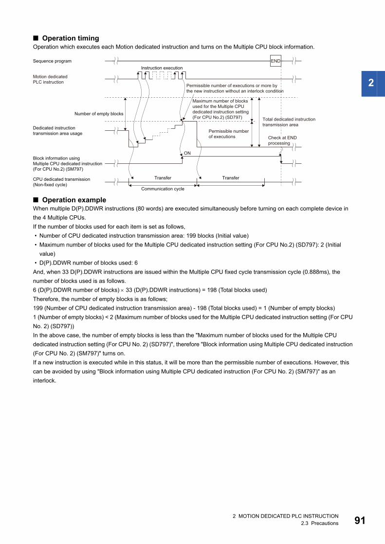
2
■ Operation timingOperation which executes each Motion dedicated instruction and turns on the Multiple CPU block information.
■ Operation exampleWhen multiple D(P).DDWR instructions (80 words) are executed simultaneously before turning on each complete device in
the 4 Multiple CPUs.
If the number of blocks used for each item is set as follows,
• Number of CPU dedicated instruction transmission area: 199 blocks (Initial value)
• Maximum number of blocks used for the Multiple CPU dedicated instruction setting (For CPU No.2) (SD797): 2 (Initial
value)
• D(P).DDWR number of blocks used: 6
And, when 33 D(P).DDWR instructions are issued within the Multiple CPU fixed cycle transmission cycle (0.888ms), the
number of blocks used is as follows.
6 (D(P).DDWR number of blocks) 33 (D(P).DDWR instructions) = 198 (Total blocks used)
Therefore, the number of empty blocks is as follows;
199 (Number of CPU dedicated instruction transmission area) - 198 (Total blocks used) = 1 (Number of empty blocks)
1 (Number of empty blocks) < 2 (Maximum number of blocks used for the Multiple CPU dedicated instruction setting (For CPU
No. 2) (SD797))
In the above case, the number of empty blocks is less than the "Maximum number of blocks used for the Multiple CPU
dedicated instruction setting (For CPU No. 2) (SD797)", therefore "Block information using Multiple CPU dedicated instruction
(For CPU No. 2) (SM797)" turns on.
If a new instruction is executed while in this status, it will be more than the permissible number of executions. However, this
can be avoided by using "Block information using Multiple CPU dedicated instruction (For CPU No. 2) (SM797)" as an
interlock.
Instruction executionSequence program END
Number of empty blocks
Motion dedicated PLC instruction
ON
CPU dedicated transmission (Non-fixed cycle)
Block information using Multiple CPU dedicated instruction(For CPU No.2) (SM797)
Dedicated instruction transmission area usage
Communication cycle
Transfer Transfer
Permissible number of executions
Maximum number of blocks used for the Multiple CPU dedicated instruction setting (For CPU No.2) (SD797)
Permissible number of executions or more bythe new instruction without an interlock condition
Total dedicated instructiontransmission area
Check at END processing
2 MOTION DEDICATED PLC INSTRUCTION2.3 Precautions 91

92
■ Program example • Program which sets 2 (Initial value) to SD797 and uses SM797 as an interlock when DP.DDWR (Number of blocks used: 2)
is executed.
• Program which sets 1 to SD797 and uses SM797 as an interlock condition when D(P).DDWR/D(P).DDRD is not executed.
DP.SFCS H3E1 K10
DP.DDWR H3E1 D0D100 W10 M100
M1 SM797
Instructionexecutioncommand
Instructionexecutioncommand
RST M1
M0 SM797
Instructionexecutioncommand
Instructionexecutioncommand
MOVP K10 D101
RST M0
DP.SFCS H3E1 K10
DP.SVST H3E1 K11"J1" M100 D100M1 SM797
Instructionexecutioncommand
Instructionexecutioncommand
RST M1
M0 SM797
Instructionexecutioncommand
Instructionexecutioncommand
MOVP K1 SD797SM402
At 1 scan after RUN
RST M0
2 MOTION DEDICATED PLC INSTRUCTION2.3 Precautions

2
Number of simultaneous acceptances for Multiple CPU dedicated instructionsThe number of instructions that can be accepted simultaneously in the Motion CPU is shown in the table below.
*1 The number of simultaneous executions is dependent on the number of CPU dedicated instruction empty blocks on the PLC CPU side.
When more than the above number of instructions are executed by the PLC CPU, even if there is enough area in the CPU
dedicated instruction transmission area, the Motion CPU cannot accept it. In this case, 2100H is set to the complete status
information and abnormal completion occurs.
Execution of Motion dedicated PLC instruction • Motion dedicated PLC instruction can be executed with a fixed cycle execute type program and interrupt program.
However, the complete device is a pulse-type. If the complete device (M100 in below example) is set, it may not be
recognized during the PLC scan. Therefore, the sequence program should scan for completion of the device and use a set
bit to execute the Motion instruction string.
• The below devices cannot be used as program file registers or local devices.
• When using the Motion dedicated function of the operation control step (Fn/FSn) and servo program (Kn) in Motion CPU, it
is necessary to create a user-defined interlock using WAIT transition (Gn) as shown below.
Instruction Number of simultaneous acceptances
M(P).SFCS/D(P).SFCS 64
M(P).SVST/D(P).SVST 256 instructions total
M(P).SVSTD/D(P).SVSTD
M(P).CHGA/D(P).CHGA
M(P).CHGAS/D(P).CHGAS
M(P).MCNST/D(P).MCNST
M(P).CHGV/D(P).CHGV No limitation*1
(The command speed and torque limit value of the instructions last executed is valid)M(P).CHGVS/D(P).CHGVS
M(P).CHGT/D(P).CHGT
M(P).DDWR/D(P).DDWR No limitation*1
(Processed in the order of issue)M(P).DDRD/D(P).DDRD
M(P).BITWR/D(P).BITWR
M(P).GINT/D(P).GINT
• Each instruction’s complete device and complete status
• M(P).DDRD/D(P).DDRD instruction of D1 (First device of the self CPU where the reading data is stored.)
MP.SVST H3E1 K11"J1" M100 D100
Normal complete programM100
Completedevice
M101
M101Abnormal complete program
M10
Gn
Kn
Gn
2 MOTION DEDICATED PLC INSTRUCTION2.3 Precautions 93

94
Complete status informationThe codes stored in complete status at the completion of Motion dedicated PLC instruction are shown below. If the complete
status storage device is omitted, an error is not detected and operation becomes "No operation".
*1 The error code is dedicated with the Motion CPU.*2 Permissible value is different depending on the number of CPU modules.
Complete status(Error code) (H)
Error factor
0 Normal completion
0010 Instruction request to Motion CPU from PLC CPU exceeds the permissible value.*2
1001*1 The specified device cannot be used in the CPU, or it is outside the device range.
1080*1 Number of writing data points set by M(P).DDWR/D(P).DDWR instruction is wrong.
1081*1 Number of reading data points set by M(P).DDWR/D(P).DDRD instruction is wrong.
2000*1 Command that cannot be decoded in the Motion CPU was specified.
2100*1 ■M(P).SFCS/D(P).SFCS instruction use
There are 65 or more simultaneous M(P).SFCS/D(P).SFCS instruction requests to the Motion CPU from the PLC CPU, therefore the
Motion CPU cannot process them.
■M(P).SVST/D(P).SVST/M(P).SVSTD/D(P).SVSTD/M(P).CHGA/D(P).CHGA/M(P).CHGAS/D(P).CHGAS/M(P).MCNST/
D(P).MCNST instruction use
There are 257 or more simultaneous M(P).SVST/D(P).SVST/M(P).SVSTD/D(P).SVSTD/M(P).CHGA/D(P).CHGA/M(P).CHGAS/
D(P).CHGAS/M(P).MCNST/D(P).MCNST instruction requests to the Motion CPU from the PLC CPU, therefore the Motion CPU
cannot process them.
2200*1 The starting Motion SFC program No. is outside the range of 0 to 511 (for operating system software version "09" or earlier, 0 to 255).
2201*1 The servo program No. to execute is outside the range of 0 to 8191 (for operating system software version "09" or earlier, 0 to 4095).
2202*1 Axis No. set by M(P).SVST/D(P).SVST instruction is wrong.
2203*1 Axis No. set by M(P).CHGA/D(P).CHGA instruction is wrong.
2204*1 Axis No. set by M(P).CHGV/D(P).CHGV instruction is wrong.
2205*1 Axis No. set by M(P).CHGT/D(P).CHGT instruction is wrong.
2207*1 Axis No. set by M(P).CHGAS/D(P).CHGAS instruction is wrong.
2208*1 Axis No. set by M(P).CHGVS/D(P).CHGVS instruction is wrong.
2209*1 Axis No. set by M(P).SVSTD/D(P).SVSTD instruction is wrong.
2220*1 Instruction area for M(P).SVSTD/D(P).SVSTD instructions is not enough. (There are 128 or more instructions in operation by
M(P).SVSTD/D(P).SVSTD instructions)
2221*1 The positioning data area points for M(P).SVSTD/D(P).SVSTD instruction is wrong.
2222*1 Instructions for M(P).SVSTD/D(P).SVSTD instructions are only NOP or resting axes.
2224*1 Positioning data items that must be set in instructions by M(P).SVSTD/D(P).SVSTD instructions have not been set.
2225*1 Character string data (d1) is wrong in M(P).SVSTD/D(P).SVSTD instructions.
2230*1 Character string data (d1) is wrong in M(P).BITWR/D(P).BITWR instructions.
2231*1 The bit operation set in the M(P).BITWR/D(P).BITWR instruction is outside the range of 0 to 1.
2240*1 Instruction area for M(P).MCNST/D(P).MCNST instructions is not enough. (There are 9 or more instructions in operation by the Motion
dedicated PLC instructions (M(P).MCNST/D(P).MCNST) and Motion dedicated function (MCNST))
2241*1 The machine positioning data area setting for M(P).MCNST/D(P).MCNST instruction is wrong.
2242*1 The control method for each point of the M(P).MCNST/D(P).MCNST instruction is wrong. (Includes when the control method for every
point is NOP only)
2243*1 Machine No. set by M(P).MCNST/D(P).MCNST instruction is wrong.
2282*1 The interrupt pointer No. set in the M(P).GINT/D(P).GINT instruction is outside the range of 0 to 15.
2 MOTION DEDICATED PLC INSTRUCTION2.3 Precautions

2
Order of instruction executionMethods to control using execution data after it is transmitted from the PLC CPU to the Motion CPU are shown below.
Method to execute after data is written to the CPU buffer memoryWrite the data from PLC CPU to the buffer memory (Fixed cycle transmission area) of the self CPU, and then it can be utilized
for Motion dedicated PLC instruction execution.
■ Program exampleProgram which starts the servo program (positioning) by DP.SVST instruction after the data has been writing to CPU buffer
memory (Fixed cycle transmission area (U3E0\HG0 to U3E0\HG3) from PLC CPU (CPU No.1).
DMOVP K10000 U3E0\HG0
DMOVP K100000 U3E0\HG2
Servo programK10 position command
Servo programK10 speed command
Instructionexecutioncommand
DP.SVST H3E1 "J1" K10 M100 D100
RST M0
Instructionexecutioncommand
K10: Real
1 INC-1 Axis 1, Speed
U3E0\HG0 �mU3E0\HG2 mm/min
Start acceptflag of CPU No.2(Axis 1)
M0
U3E1\G516.0
Sequence program (PLC CPU side)
Servo program (Motion CPU side)
2 MOTION DEDICATED PLC INSTRUCTION2.3 Precautions 95

96
Method to execute after data is written by M(P).DDWR/D(P).DDWR instructionWrite the data from the PLC CPU to the Motion CPU by M(P).DDWR/D(P).DDWR instruction, and then it can be utilized for
Motion dedicated PLC instruction execution.
■ Program exampleProgram which starts the servo program (positioning) by MP.SVST instruction after data is written to D3000 to D3002 of the
Motion CPU (CPU No.2) from the PLC CPU (CPU No.1) by MP.DDWR.
DMOVP K10000 D0
Servo programK10 positioncommand
Servo programK10 speedcommand
Instructionexecutioncommand
MP.SVST H3E1 "J1" K10 M100 D100
MP.DDWRH3E1 D50 D0 D3000 M50
RST M0
DMOVP K100000 D2
Number of writing datapoints
MOVP K4 D51
Instructionexecutioncommand
Start acceptflag of CPUNo.2(Axis 1)
K10: Real
1 INC-1 Axis 1, Speed
D3000 �mD3002 mm/min
M0
U3E1\G516.0
Sequence program (PLC CPU side)
Servo program (Motion CPU side)
2 MOTION DEDICATED PLC INSTRUCTION2.3 Precautions

3
3 MOTION SFC PROGRAMS
3.1 Motion SFC Program ConfigurationThe Motion SFC Program is constituted by the combination of start, steps, transitions, end and others are shows below.
The above Motion SFC program to be started performs the following operations.
1. The step (F0) is activated and the operation specified with the step (F0) is executed (positioning ready). A step in such
an active state is called an active step.
2. Whether the condition specified with the transition (G0) has enabled or not (whether the positioning program can be
started or not) is checked. The active step (F0) is deactivated at the completion of condition and the next step (K0) is
activated. (Servo program (K0) is started)
3. The operating completion of the step (K0) (positioning completion of the servo program K0) is checked, and control
transits to the next step at operating completion (completion of condition).
4. With the transition of the active step as described in above 1. to 3., control is executed and ends at END.
Refer to the task operation for details of the execution timing of the Motion SFC program such as above. (Page 286 Task
operation)
The combined number of steps for all Motion SFC programs which can be active simultaneously is up to 1024
(for operating system software version "08" or earlier, up to 256). Exceeding 1024 steps will result in the minor
error(SFC) (error code: 33FEH). Each symbol of the Motion SFC program is as follows.
F/FS: Operation control, K: Positioning control, G: Judgment
Step (operation control step): The specified operation control program is executed at active status.
END: Program end.
Transition (WAIT): Condition to transit to the next step
Step (motion control step): The specified servo program is executed at active status.
Transition (shift): Condition to transit to the next step.
Positioningready
Operation start
Operation end
Positioningready check
Positioningcomplete check
Positioningexecution
F0
Program name
G0
K0
G1
END
START: Entry of program.
SET Y0=X0+X10D100=W0+W100
Y0*M100
ABS-1Axis 1, D100Speed 10000
!X0
3 MOTION SFC PROGRAMS3.1 Motion SFC Program Configuration 97

98
3.2 Motion SFC Chart Symbol ListParts as Motion SFC program components are shown below. The operation sequence or transition control is expressed with
connecting these parts by directed lines in the Motion SFC program.
Classification Name Symbol(Code size (byte))
Function
Program start/
end
START
(0)
• Indicates an entry of program as a program name.
• Specify this program name at a subroutine call.
• Only one program name for one program.
END
(8)
• Indicates an end (exit) of program.
• When a subroutine call was carried out, returns to the call source
program.
• Multiple program names or no symbols for one program.
Step Motion control step
(8)
Starts a servo program Kn (K0 to K8191)*1.
Once execution type
operation control step
(8)
Execute once the operation control program Fn (F0 to F4095).
Scan execution type
operation control step
(8)
Repeats an operation control program FSn (FS0 to FS4095) until the
next transition condition enables.
Subroutine call/start step
(8)
• When the next of GSUB is WAIT, performs "subroutine call" and
transits control to the specified program. Control returns to the call
source program at END execution.
• When the next of GSUB is except WAIT, performs "subroutine start",
and starts the specified program and transits to the next (lower part).
The start source and destination programs are executed
simultaneously, and the call destination program ends at END
execution.
Clear step
(8)
• Stops and ends the specified program running. After an end, it is
started from the initial (start step) by restarting the program.
• When the specified program is during "subroutine call", the subroutine
program is also stopped to execute.
• When the specified program is after "subroutine start", the subroutine
program is not stopped to execute.
• When clearing to the subroutine by which the "subroutine call" was
executed, the specified subroutine is stopped to execute, returns to the
call source program, and transits to the next.
Program name
END
Kn
Fn
FSn
Program name
Program nameCLR
3 MOTION SFC PROGRAMS3.2 Motion SFC Chart Symbol List

3
*1 For operating system software version "09" or earlier, K0 to K4095.
Transition Shift (Pre-read transition)
(8)
• When just before is the motion control step, transits to the next step by
formation of transition condition Gn (G0 to G4095) without waiting for
the motion operating completion.
• When just before is the operation control step, transits to the next step
by the completion of transition condition after operating execution.
• When just before is subroutine call or starting step, transits to the next
step by formation of transition condition without waiting for the
operating completion of subroutine.
WAIT
(8)
• When just before is the motion control step, waits for the motion
operating completion and then transits to the next step by the
completion of transition condition Gn (G0 to G4095).
• When just before is the operation control step, transits to the next step
by formation of transition condition after operating execution. (Same
operation as Shift.)
• When just before is subroutine call or starting step, waits for the
operating completion of subroutine and then transits to the next step
by the completion of transition condition.
WAITON
(14)
• Prepares for starting of the next motion control step, and issues an
instruction immediately when the specified bit device turns ON.
• Always pair this transition with the motion control step one-for-one.
WAITOFF
(14)
• Prepares for starting of the next motion control step, and issues an
instruction immediately when the specified bit device turns OFF.
• Always pair this transition with the motion control step one-for-one.
Shift Y/N • When just before is the motion control step, transits to the next step by
formation of transition condition Gn (G0 to G4095) without waiting for
the motion operating completion. If not formation of transition
condition, transits to the right-connected step.
• When just before is the operation control step, transits to the next step
by the completion of transition condition after operating execution. If
not the completion of transition condition, transits to the right-
connected step.
• When just before is "subroutine call" or "starting step", transits to the
next step by the completion of transition condition without waiting for
the operating of subroutine completion. If not formation of transition
condition, transits to the right-connected step.
WAIT Y/N • When just before is the motion control step, waits for the motion
operating completion and then transits to the next step by formation of
transition condition Gn (G0 to G4095). If not completion of transition
condition, transits to the right-connected step.
• When just before is the operation control step, transits to the next step
by the completion of transition condition after operating execution. If
not the completion of transition condition, transits to the right-
connected step. (Same operation as Shift.)
• When just before is subroutine call or starting step, waits for the
operating completion of subroutine, and then transits to the next step
by the completion of transition condition. If not formation of transition
condition, transits to the right-connected step.
Jump Jump
(14)
Jumps to the specified pointer Pn (P0 to P16383) of the self program.
Pointer Pointer
(8)
• Indicates a jump destination pointer (label).
• This pointer can be set at a step, transition, branch point or coupling
point.
• P0 to P16383 can be set in one program. The same No. may also be
used in other programs.
Classification Name Symbol(Code size (byte))
Function
Gn
Gn
ON bit device
Kn
OFF bit device
Kn
(Not completion of condition)
(Completion of condition)
GnN
Y
(Not completion of condition)
(Completion of condition)
GnN
Y
Pn
Pn
3 MOTION SFC PROGRAMS3.2 Motion SFC Chart Symbol List 99

10
3.3 Branch and Coupling Chart ListBranch and coupling patterns which specify step and transition sequences in the Motion SFC charts are shown below.
Classification Name(Code size (byte))
Motion SFC chart symbol Function
Basic type Series transition
(Corresponding symbol size)
• Steps and transitions connected in series are
processed in order from top to bottom.
• Steps and transitions need not be lined up
alternately.
• When a transition is omitted, unconditional
shift processing is performed.
Selective branch
((Number of branches + 2) 10)
• The route which transition condition enables
first is executed after executing the step or
transition preceding a branch.
• Selective branch destinations should always
be started by transitions, all of which must be
Shift or WAIT. (Using Shift and WAIT together
will cause a parallel branch.)
Selective coupling
(8)
• After the route branched by a selective branch
has been processed, execution shifts to a
coupling point.
• A coupling may be preceded and followed by
either a step or a transition.
Parallel branch
(Number of branches 22 +
number of coupling points 2 + 12)
• Multiple routes (steps) connected in parallel
are executed simultaneously.
• Each parallel branch destination may be
started by either a step or transition.
Parallel coupling
(8)
• Execution waits at the coupling point for
executions of the routes branched by a parallel
branch to be completed, and shifts to the next
when executions of all routes are completed.
• A coupling may be preceded and followed by
either a step or a transition.
• When this coupling is preceded by an FS step,
scans are executed during waiting. After
waiting is complete, scans are not executed.
Jump transition
(Corresponding symbol size)
[Normal jump]
• After the step or transition preceding this jump
transition is executed, execution shifts to the
pointer Pn specified within its own program.
• The jump destination may either be a step or
transition.
• When a jump takes place from an FS step to a
transition, scans are executed during waiting
for the completion of transition condition of the
jump destination.
[Coupling jump]
• When a jump to the other route within a
parallel branch takes place after the parallel
branch, a "coupling jump" takes place and
execution waits at the jump destination.
IFT1
IFBm
IFT2
IFEm
PAT1
PABm
PAT2
PAEm
[Normal jump]
[Coupling jump]
03 MOTION SFC PROGRAMS3.3 Branch and Coupling Chart List

3
Combining the basic type branches/couplings provides the following application types, which are defined as in the basic
types.
Classification Name Motion SFC chart symbol Function
Application type Selective branch
|
Parallel branch
After a selective branch, a parallel branch can be
performed.
Parallel coupling
|
Selective coupling
• The selective coupling point can be the same as
the coupling point of a parallel coupling for
selective branch parallel branch. Note that in the
Motion SFC chart, this type is displayed in order of
a parallel coupling a selective coupling, as
shown on the left.
• In this case, a pointer (Pn) cannot be set between
the parallel coupling point (PAEm) and the
selective coupling point (IFEm).
Parallel branch
|
Selective branch
After a parallel branch, a selective branch can be
performed.
Selective coupling
|
Parallel coupling
• The parallel coupling point can be the same as the
coupling point of a selective coupling for parallel
branch selective branch. Note that in the Motion
SFC chart, this type is displayed in order of a
selective coupling a parallel coupling, as shown
on the left.
• In this case, a pointer (Pn) cannot be set between
the selective coupling point (IFEm) and the parallel
coupling point (PAEm).
Selective branch
|
Selective branch
After a selective branch, a selective branch can be
performed.
Selective coupling
|
Selective coupling
• The two selective coupling points for selective
branch selective branch can be the same. Note
that in the Motion SFC chart, this type is displayed
in order of a selective coupling a selective
coupling, as shown on the left.
• In this case, a pointer (Pn) cannot be set between
the selective coupling point (IFEm+1) and the
selective coupling point (IFEm).
Parallel branch
|
Parallel branch
• After a parallel branch, a parallel branch can be
performed.
• A parallel branch can be nested up to four levels.
IFT1
PAT1 PAT2
IFBm
PABm
IFT2
PAEmIFEm
PAT1
IFT1 IFT2
PABm
IFBm
PAT2
IFEmPAEm
IFT1
IFT1 IFT2
IFBm
IFBm+1
IFT2
IFEm+1IFEm
PAT1
PAT1 PAT2
PABm
PABm+1
PAT2
3 MOTION SFC PROGRAMS3.3 Branch and Coupling Chart List 101

10
Application type Parallel coupling
|
Parallel coupling
• The two parallel coupling points for parallel branch
parallel branch can be the same. Note that in the
Motion SFC chart, this type is displayed in order of
a parallel coupling a parallel coupling, as shown
on the left.
• In this case, a pointer (Pn) cannot be set between
the parallel coupling point (PAEm+1) and the
parallel coupling point (PAEm).
Selective coupling
|
Parallel branch
• The selective coupling point and parallel branch
point can be the same. Note that in the Motion SFC
chart, this type is displayed in order of a selective
coupling a parallel branch, as shown on the left.
• In this case, a pointer (Pn) cannot be set between
the selective coupling point (IFEm) and the parallel
branch point (PABm).
Parallel coupling
|
Selective branch
• The parallel coupling point and selective branch
point can be the same. Note that in the Motion SFC
chart, this type is displayed in order of a parallel
coupling a selective branch, as shown on the
left.
• Execution waits at the parallel coupling point and
shifts to the selective branch.
• In this case, a pointer (Pn) cannot be set between
the parallel coupling point (PAEm) and the
selective branch point (IFBm).
Selective coupling
|
Selective branch
• The selective coupling point and selective branch
point can be the same. Note that in the Motion SFC
chart, this type is displayed in order of a selective
coupling a selective branch, as shown on the
left.
• In this case, a pointer (Pn) cannot be set between
the selective coupling point (IFEm) and the
selective branch point (IFBm+1).
Parallel coupling
|
Parallel branch
• The parallel coupling point and parallel branch
point can be the same. Note that in the Motion SFC
chart, this type is displayed in order of a parallel
coupling a parallel branch, as shown on the left.
• Execution waits at the parallel coupling point and
shifts to the parallel branch.
• In this case, a pointer (Pn) cannot be set between
the parallel coupling point (PAEm) and the parallel
branch point (PABm+1).
Classification Name Motion SFC chart symbol Function
PAEm+1PAEm
IFEmPABm
PAT1 PAT2
PAEmIFBm
IFT1 IFT2
IFEmIFBm+1
IFT1 IFT2
PAEmPABm+1
PAT1 PAT2
23 MOTION SFC PROGRAMS3.3 Branch and Coupling Chart List

3
3.4 Motion SFC Program NameSet the "Motion SFC program name" to the Motion SFC program No.0 to No.511 (for operating system software version "09"
or earlier, No.0 to No.255) individually. Set the Motion SFC program name within 16 characters. Specify this Motion SFC
program name for a "subroutine call/start step (GSUB)" and "clear step (CLR)".
• The Motion SFC program can be set to any No. from No.0 to No.511. There are no specific programs which
have special roles.
• "$" cannot be used in the first character of the Motion SFC program name.
• "\ / : ; , . * ? " < > |" cannot be used in Motion SFC program name.
3 MOTION SFC PROGRAMS3.4 Motion SFC Program Name 103

10
3.5 Steps
Motion control step
*1 For operating system software version "09" or earlier, K0 to K4095.
Processing details
• Turns on the start accept flag of the axis specified with the specified servo program Kn running.
• Starts the specified servo program Kn.
■ Execution timing
Operation error
When the specified servo program Kn does not exist, the minor error (SFC) (error code: 31F0H) will occur and stops to
execute the Motion SFC program at the error detection.
Precautions
• When the current value change is executed in the Motion SFC program running, specify the CHGA instruction in the servo
program and call it at the motion control step.
• If the servo program has stopped due to a minor error which occurred at or during a start of the servo program specified
with the motion control step, the Motion SFC program continues executing. When the Motion SFC program is stopped at
error detection, provide an error detection condition at the transition (transition condition).
• Refer to the following for servo programs that can be described in Motion control steps.
MELSEC iQ-R Motion Controller Programming Manual (Positioning Control)
Name Symbol Setting range
Motion control step K0 to K8191*1
Kn
t
V
Completion of transition condition
[St.1040] Start accept flag (R: M30080+n/Q: M2001+n)
43 MOTION SFC PROGRAMS3.5 Steps

3
Operation control step
Processing details
■ Once execution type operation control step FnIn the case of Fn, executes the specified operation control program Fn once.
■ Scan execution type operation control step FSnIn the case of FSn, repeats the specified operation control program FSn until the next transition condition enables.
Operation error
When the specified operation control program Fn/FSn does not exist, the minor error (SFC) (error code: 31F1H) will occur and
stops to execute the Motion SFC program at the error detection.
Precautions
• Refer to the operation control programs for operation expressions that may be described in operation control programs.
(Page 122 OPERATION CONTROL PROGRAMS)
• If an operation or similar error occurs the operation control program running, the Motion SFC program continues executing.
Name Symbol Setting range
Operation control step F0 to F4095/FS0 to FS4095
Fn/FSn
3 MOTION SFC PROGRAMS3.5 Steps 105

10
Subroutine call/start step
Processing details
• Calls/starts the Motion SFC program of the specified program name.
• Control varies with the type of the transition coupled next to the subroutine call/start step.
■ WAIT (Subroutine Call)When the subroutine call step is executed, control transits to the specified program as shown below, and when END of the
called program is executed, control returns to the call source program.
■ Except WAIT (Subroutine Start)When the subroutine start step is executed, control starts the specified program and then shifts to the next as shown below.
Since, the start source and destination Motion SFC programs are executed in parallel. The started program ends at END
execution.
Operation error
• When the specified Motion SFC program does not exist at a subroutine call/start, the minor error (SFC) (error code: 32F5H)
will occur and stops to execute the Motion SFC program at the error detection.
• When the called/started Motion SFC program is already starting at a subroutine call/start, the minor error (SFC) (error code:
32F6H) will occur and stops to execute the Motion SFC program at the error detection.
• When the self program is started at a subroutine call/start, the minor error (SFC) (error code: 33FAH) will occur and stops to
execute the Motion SFC program at the error detection.
• When the subroutine to be called/started at a subroutine call/start in the Motion SFC program 2 running which was called/
started from the Motion SFC program 1 is the Motion SFC program 1 (call source/start program), the minor error (SFC)
(error code: 33FBH) will occur and the call/start source Motion SFC program 2 running is stopped at the point of error
detection.
Precautions
• There are no restrictions on the depth of subroutine call/start nesting.
• For a subroutine start, the start source Motion SFC program continues processing if the start destination Motion SFC
program stops due to an error.
• For a subroutine call, the call source Motion SFC program stops running as soon as the call destination Motion SFC
program stops due to an error.
Name Symbol Setting range
Subroutine call/start step The registered program name
Program name
WAIT(Subroutine call)
MAIN
END
SUB (2)(3)
(4)
(1)
(5)WAIT
SUB
END
Except WAIT(Subroutine start)
MAIN
END
SUB (2)(3)
(1)
(2)shift
SUB
END
63 MOTION SFC PROGRAMS3.5 Steps

3
Clear step
Processing details
• Stops the specified Motion SFC program running.
• The clear-specified Motion SFC program will not start automatically after stopped if it has been set to start automatically.
• The specified program may be its self program.
• If the specified program is being subroutine called, the subroutine program called is also stopped. (Shown below)
• When the specified program has been subroutine started, the subroutine program started continues processing. (Shown
below)
• When the servo program started from the specified program is starting, the servo program continues processing.
• The servo program is executed after waiting completion of condition in "WAITON/WAITOFF + motion control step". Input
the stop command of target axis in addition not to execute the servo program.
Operation error
When a SFC program that does not exist is specified by clear step, an error occurs if the Motion SFC program is converted in
MT Developer2.
Precautions
• When the Motion SFC program specified with the clear step is not starting, an error does not occur specifically and this step
is ignored.
• If the Motion SFC program running is stopped by the clear step, the output is held.
• Input the stop command of target axis in addition to stop an operating axis with the clear step execution.
Name Symbol Setting range
Clear step The registered program name
Program nameCLR
MAIN
END
SUB
WAIT
SUB
END
If the program has been "subroutine called" as shown on the leftWhen the call source program (MAIN) is cleared.Even if the subroutine (SUB) is running, both the call sourceprogram (MAIN) and subroutine (SUB) stop running.When the subroutine (SUB) is running, the subroutine (SUB)stops running and execution to the call source program (MAIN).
MAIN
END
SUB
Shift
SUB
END
If the program has been "subroutine started" as shown on the leftWhen the started program (MAIN) is cleared.Even if the subroutine (SUB) is running, the started program(MAIN) stops running but the started subroutine (SUB)continues processing.When the subroutine (SUB) is clearedIf the subroutine (SUB) is running, only the subroutine (SUB)stops running.
3 MOTION SFC PROGRAMS3.5 Steps 107

10
3.6 TransitionsYou can describe conditional and operation expressions at transitions. The operation expression described here is repeated
until the transition condition enables, as at the scan execution type operation step. Refer to the transition programs for the
conditional/operation expressions that can be described in transition conditions. (Page 283 TRANSITION PROGRAMS)
Combinations with motion control steps
Processing details
■ Motion control step + Shift • Transits to the next step by formation of transition condition Gn without waiting for the operating completion of the servo
program Kn started at the motion control step.
■ Motion control step + WAIT • Waits for the operating completion of the servo program Kn started at the motion control step, and then transits to the next
step by formation of transition condition Gn.
• The operation completion condition of the servo program Kn is not needed in the transition condition Gn.
• An error stop of the started servo program Kn at/during a start is also regarded as an operation completion.
■ WAITON/WAITOFF + Motion control step • Prepares for the start of the motion control step next to WAITON/WAITOFF, and makes a start immediately when the
specified bit device turns ON/OFF. When the motion control step is executed without being used with WAITON/WAITOFF,
preparations for a start are made after the transition condition preceding the motion control step enables. This will cause a
variation of delay/starting time between when the transition condition is completed and when a start is made, but a
combination with WAITON/WAITOFF can eliminate the variation of the above delay/starting time.
• Refer to the following for details of bit devices which can be set to WAITON/WAITOFF.
MELSEC iQ-R Motion Controller Programming Manual (Common)
Kn
Gn
Kn
Gn
ON M0
Kn
OFF M0
Kn
83 MOTION SFC PROGRAMS3.6 Transitions

3
Precautions
• Always pair a transition with a motion control step one-for-one. If the step following WAITON/WAITOFF is not a motion
control step, the minor error (SFC) (error code:33F2H) will occur and the Motion SFC program running will stop at the error
detection.
• An error will not occur if the jump destination immediately after WAITON/WAITOFF is a motion control step. (Left below)
• A pointer may exist immediately after WAITON/WAITOFF. (Right below)
• If the servo program specified with a motion control step could not be started due to minor error, the Motion SFC program
continues running and execution shifts to the next, independently of the WAITON/WAITOFF bit device status. To stop the
Motion SFC program at error detection, provide an error detection condition at the next transition (transition condition).
• The following instructions can be used in the motion control step used combining the WAITON/WAITOFF. (Linear
interpolation control, circular interpolation control, helical interpolation, position follow-up control, continuous trajectory
control, high speed oscillation and speed control with fixed position stop.)
Combination with operation control step
Processing details
• At an operation control step, both Shift and WAIT perform the same operation, and after executing of the operation control
program Fn, transits to the next step by formation of transition condition Gn.
Combination with subroutine call/start stepRefer to the subroutine call/start step for the combination with subroutine call/start step. (Page 106 Subroutine call/start
step)
ON M0 Gn
Kn
Pn
Kn
Pn
Pn
Gn Gn
Fn Fn
3 MOTION SFC PROGRAMS3.6 Transitions 109

11
3.7 Jump, Pointer
Processing details
• Setting a jump will cause a jump to the specified pointer Pn of the self program.
• You can set pointers at steps, transitions, branch points and coupling points.
• You can set pointers Pn at P0 to P16383 in one program.
Precautions
• You cannot make a jump setting which will exit from within parallel branch-parallel coupling. Connect directly. (Bad example
1 given below)
• You cannot make a jump setting from outside parallel branch-parallel coupling to within parallel branch-parallel coupling.
(Bad example 2 given below)
• You cannot make a setting where a label and a jump will continue. (Bad example 3 given below)
Name Symbol Setting range
Jump P0 to P16383
Pointer P0 to P16383
Pn
Pn
Pn
Pn
Bad example 1
Pn
Pn
Bad example 2
Pn
Pn
Bad example 3
03 MOTION SFC PROGRAMS3.7 Jump, Pointer

3
3.8 END
Processing details
• Ends a program. (In this case of an event task or NMI task, operation changes with end operation setting of the program
parameter. (Page 294 Program Parameters)
• Making a subroutine call will return to the call source Motion SFC program.
Precautions
• END may be set a multiple number of times in one program.
• END cannot be set between a parallel branch and a parallel coupling.
• The output is held after the Motion SFC program is ended by END.
Name Symbol Setting range
END
END
3 MOTION SFC PROGRAMS3.8 END 111

11
3.9 Branches, Couplings
Series transitionTransits execution to the subsequent step or transition connected in series. To start a servo program or subroutine and transit
to the next step, set a shift, or a WAIT at a transition.
To transit to the next step without waiting for operation completionSet Shift at a transition. In this case, the transition (shift) may be omitted. When you omitted the transition, an unconditional
shift transition is performed.
For a subroutine start, self program and a subroutine program are processed in parallel.
To proceed to the next step on operation completionSet WAIT at a transition.
• The above start accept flag of the axis started in the next servo program K2 is not included in interlocks. To
use it as an interlock, the user should set it in the transition condition G1.
• WAIT must be set to proceed to the next step on operation completion. However, when there are specifically
no conditions to be set as interlocks, set "NOP (No Operation)" in the transition program (Gn).
K1
G1
K2
Starts the servo program K1.
Starts the servo program K2.
Transits to next by the completion of condition set at transition G1without waiting for operating completion of the servo program K1.
Starts the servo program K2.
K1
G1
K2
Starts the servo program K1.
Transits to next when the start axis stops in the servo program K1 (start accept flag turns OFF) and condition is completed set at transition G1.
23 MOTION SFC PROGRAMS3.9 Branches, Couplings

3
Selective branch, selective coupling
Selective branchExecutes only the route which condition was judged to have enabled first among the conditions of multiple transitions
connected in parallel. Transitions must be all Shifts or WAITs.
Ex.
WAIT
• Transition condition judgment is not always executed from left to right.
• Using Shift and WAIT together will cause a parallel branch.
• When judging transition condition by selective branch, the number of multi active steps is "number of
selective branches + 1". If the number of selective branches is 255, the number of multi active steps is 256.
Selective couplingRecoupling of routes into a single route after their processing completions following a selective branch will be a selective
coupling. However, you can also make a setting where no coupling will be made as shown below.
K1
G1
K2 K3 K4 K255
After start axis in the servoprogram K1 has stopped (startaccept flag turns OFF), theconditions of transitions G1 toG255 are judged, and executiontransits to route which conditionis completed.
G2 G3 G255
Max. number of selective branches = 255
Starts the servo program K1.
END Program END
IFB1
IFE2
Jump transition (normal jump)P0
P0
3 MOTION SFC PROGRAMS3.9 Branches, Couplings 113

11
Parallel branch, parallel coupling
Parallel branchMultiple routes connected in parallel are executed simultaneously. Each parallel branch destination may be started by either a
step or a transition.
"Shift" or "WAIT" can be set to a transition preceding a parallel branch. "WAITON" and "WAITOFF" cannot be
set.
Parallel couplingA parallel branch must be coupled by a parallel coupling. A jump setting to another branch route can be made within parallel
branch-parallel coupling. In this case, a jump destination is a midway parallel coupling point (coupling jump). You cannot set a
jump to exit from within parallel branch-parallel coupling.
The number of parallel branches need not match that of couplings at a parallel coupling point. (In the example
of the diagram above, the number of parallel branches is 3 and that of couplings is 2.)
F10K2 K3 F1
G1
G0
After operation completion of preceding step, steps K2 to F10connected in parallel areexecuted when the completionof condition set at transition G0.Thereafter, routes are executedsimultaneously up to parallelcoupling point.
G2 G3 G255
Max. number of parallel branches = 255
K2 K4 F10
ON M100
K3
G3
K100
K5
G1
G11
F11
After the servo program K3 hascompleted stopping, execution waitsuntil the completion of condition setat transition G3 and servo programK4 completes starting.On completion of waiting, executiontransits to the next (lower part).
G12
F12
PAB1
PAE1
Coupling jump
Parallel branch point
Parallel coupling point
43 MOTION SFC PROGRAMS3.9 Branches, Couplings

3
When a WAIT transition is set right after a parallel coupling, the stop completions of the axes are not included in the waiting
conditions if the parallel coupling is preceded by motion control steps. To perform a parallel coupling on stop completions, set
WAIT transitions before a parallel coupling.
K2 K3 K4 K5
G1
Parallel coupling
If this is WAIT, stop completions of axes started at K2 to K5are not included in transition conditions.
K2 K3 K4 K5
G2 G3 G4 G5
G1
Parallel coupling
When you want to perform acoupling on stop completionsof axes started in K2 to K5,set WAIT transition in eachroute to make parallel coupling.
( )
( )
3 MOTION SFC PROGRAMS3.9 Branches, Couplings 115
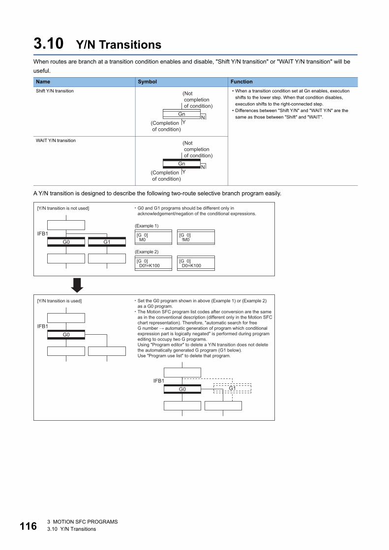
11
3.10 Y/N TransitionsWhen routes are branch at a transition condition enables and disable, "Shift Y/N transition" or "WAIT Y/N transition" will be
useful.
A Y/N transition is designed to describe the following two-route selective branch program easily.
Name Symbol Function
Shift Y/N transition • When a transition condition set at Gn enables, execution
shifts to the lower step. When that condition disables,
execution shifts to the right-connected step.
• Differences between "Shift Y/N" and "WAIT Y/N" are the
same as those between "Shift" and "WAIT".
WAIT Y/N transition
(Not completion of condition)
(Completion of condition)
GnN
Y
(Not completion of condition)
(Completion of condition)
GnN
Y
G0[G 0] M0
(Example 1)
[Y/N transition is not used]
[G 0] !M0
[G 0] D0!=K100
(Example 2)
[G 0] D0=K100
G1IFB1
[Y/N transition is used]
G0IFB1
G1G0IFB1
G0 and G1 programs should be different only inacknowledgement/negation of the conditional expressions.
Set the G0 program shown in above (Example 1) or (Example 2)as a G0 program.The Motion SFC program list codes after conversion are the sameas in the conventional description (different only in the Motion SFCchart representation). Therefore, "automatic search for free G number → automatic generation of program which conditionalexpression part is logically negated" is performed during programediting to occupy two G programs. Using "Program editor" to delete a Y/N transition does not deletethe automatically generated G program (G1 below). Use "Program use list" to delete that program.
63 MOTION SFC PROGRAMS3.10 Y/N Transitions

3
Automatic free G number search feature
■ When not set to automatic numberingSearches for a free number forward, starting with the "set G number + 1" at the "Shift Y/N" or "WAIT Y/N" symbol. When no
free numbers are found after a search up to 4095, a search is made from 0 to the "set G number - 1".
■ When set to automatic numberingSearches for a free number forward (or backward) in the automatic numbering range, starting with the "automatically
numbered G number + 1 (or -1)" at the "Shift Y/N" or "WAIT Y/N" symbol. (The searching method is as in the automatic
numbering setting.)
Automatic logical NOT program generation featureAutomatically generates a program which logically negates the conditional expression block (last block) of the transition
program set at "Shift Y/N" or "WAIT Y/N". The basic is shown below.
Examples are shown below.
• Refer to the table of the operation control/transition instruction for the instructions usable in the conditional
expressions of "Shift Y/N" or "WAIT Y/N" transition programs. (Page 23 Table of the operation control/
transition instruction)
• Set conditional expression block only to the setting program.
• For Y/N transitions, there are 2 transition condition judgments by selective branching, therefore the number
of multi active steps is 3 steps.
[Setting program (conditional expression block)]
Conditional expression//(bit conditional expression or comparison conditional expression)
[Logically negated, automatically generated program (conditional expression block)]
!Conditional expression//(bit conditional expression or comparison conditional expression)
(Example 1)
M0
(Example 2)
D0!=K100
//Bit device OFF
//Data register D0 is K100
[Setting program (conditional expression block)] [Logically negated, automatically generated program(conditional expression block)]
!(M0)//Bit device ON
!(D0!=K100)//Data register D0 is not K100
3 MOTION SFC PROGRAMS3.10 Y/N Transitions 117

11
Instructions for the Motion SFC chartsAny Motion SFC chart that will be meaningless to or conflict with the definition of Y/N transitions will result in an error at the
time of editing (or Motion SFC chart conversion). Their patterns and instructions will be given below.
■ When "Shift Y/N" or "WAIT Y/N" is connected as a selective branch or parallel branchThe following patterns result in an error
■ When a coupling precedes "Shift Y/N" or "WAIT Y/N"Provide "coupling-branch continuation" in between.
Description Motion SFC chart pattern
"Shift Y/N" used as selective branch
"WAIT Y/N" used as selective branch
"Shift Y/N" and "WAIT Y/N" used as parallel branch
"Shift (or WAIT) Y/N" used with other step/transition as parallel branch or
selective branch
Description Motion SFC chart pattern
Direct coupling with "Shift Y/N" or "WAIT Y/N" is not allowed.
Provide "coupling-branch continuation" in between.
83 MOTION SFC PROGRAMS3.10 Y/N Transitions

3
■ Patterns that may be setThe following patterns may be set.
Description Motion SFC chart pattern
End (END) from "Shift Y/N" or "WAIT Y/N"
Jump from "Shift Y/N" or "WAIT Y/N"
Continuation from "Shift Y/N" or "WAIT Y/N" to "Shift Y/N" or "WAIT Y/N"
(selective branch-selective branch)
When there are two or more connection lines from Y/N side of "Shift Y/N" or
"WAIT Y/N", selective branch continues to selective branch or parallel
branch.
END
P2P1
END
3 MOTION SFC PROGRAMS3.10 Y/N Transitions 119

12
3.11 Motion SFC CommentsA comment can be set to each symbol of the step/transition in the motion SFC chart. Comments are shown in the Motion SFC
chart by changing the display mode to "Comment display" on the Motion SFC program edit screen.
Classification Name Symbol Comment Setting
Program start/end START Comment setting cannot be made.
END
Step Motion control step Up to 80 characters
Displayed in 20 characters 4 lines
Once execution type operation control step
Scan execution type operation control step
Subroutine call/start step
Clear step
Transition Shift (preread transition)
WAIT
WAITON
WAITOFF
Shift Y/N
WAIT Y/N
Jump Jump Up to 64 characters
Displayed in 16 characters 4 lines
Pointer Pointer
Program name
END
Kn
Fn
FSn
Program name
Program nameCLR
Gn
Gn
ON bit device
OFF bit device
Gn
Gn
Pn
Pn
03 MOTION SFC PROGRAMS3.11 Motion SFC Comments

3
• Motion SFC comments are stored into the code area of Motion CPU. The code area stores the Motion SFC
chart codes, operation control (F/FS) program codes, transition (G) program codes and Motion SFC
comments. Be careful not to set too many comments to avoid code area overflow. (Refer to Motion SFC
performance specifications for the code area sizes.) (Page 20 Motion SFC performance specifications))
• You cannot use "," in comment statements.
3 MOTION SFC PROGRAMS3.11 Motion SFC Comments 121
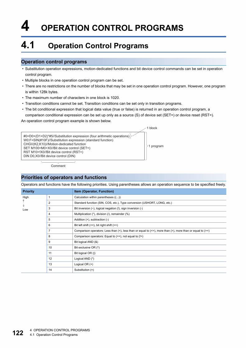
12
4 OPERATION CONTROL PROGRAMS
4.1 Operation Control Programs
Operation control programs • Substitution operation expressions, motion-dedicated functions and bit device control commands can be set in operation
control program.
• Multiple blocks in one operation control program can be set.
• There are no restrictions on the number of blocks that may be set in one operation control program. However, one program
is within 128k bytes.
• The maximum number of characters in one block is 1020.
• Transition conditions cannot be set. Transition conditions can be set only in transition programs.
• The bit conditional expression that logical data value (true or false) is returned in an operation control program, a
comparison conditional expression can be set up only as a source (S) of device set (SET=) or device reset (RST=).
An operation control program example is shown below.
Priorities of operators and functionsOperators and functions have the following priorities. Using parentheses allows an operation sequence to be specified freely.
Priority Item (Operator, Function)
High
Low
1 Calculation within parentheses ((...))
2 Standard function (SIN, COS, etc.), Type conversion (USHORT, LONG, etc.)
3 Bit inversion (~), logical negation (!), sign inversion (-)
4 Multiplication (*), division (/), remainder (%)
5 Addition (+), subtraction (-)
6 Bit left shift (<<), bit right shift (>>)
7 Comparison operators: Less than (<), less than or equal to (<=), more than (>), more than or equal to (>=)
8 Comparison operators: Equal to (==), not equal to (!=)
9 Bit logical AND (&)
10 Bit exclusive OR (^)
11 Bit logical OR (|)
12 Logical AND (*)
13 Logical OR (+)
14 Substitution (=)
#0=D0+(D1+D2)*#5//Substitution expression (four arithmetic operations)W0:F=SIN(#10F)//Substitution expression (standard function)CHGV(K2,K10)//Motion-dedicated functionSET M100=M0+X0//Bit device control (SET=)RST M10=!X0//Bit device control (RST=)DIN D0,X0//Bit device control (DIN)
1 program
1 block
Comment
24 OPERATION CONTROL PROGRAMS4.1 Operation Control Programs

4
Structure of instructionMany of the instructions usable in operation control programs can be divided into instruction and data parts. The instruction
and data parts are used for the following purposes.
• Instruction part: Indicates the function of that instruction.
• Data part: Indicates the data used in the instruction.
Ex.
"Substitution: =" structure example
■ Source (S) • The source is the data used in an operation.
• It varies with the device specified in each instruction is shown below.
■ Destination (D) • As the destination data, after-operation data is stored.
• Destination data is always set the device for storing the data.
How to specify dataThere are the following six different data usable in each instruction.
■ 16-bit integer type dataThe 16-bit integer type data is 16-bit integer value data. Word devices are used in increments of 1 point. Data ranges are
shown below.
■ 32-bit integer type dataThe 32-bit integer type data is 32-bit integer value data. Word devices are used in increments of 2 points: (specified device
No.), (specified device No. + 1). Data ranges are shown below.
Device Description
Bit or word device Specify the device which stores the data used in operation. The data must have been stored in the specified device
until the operation is executed. Changing the data stored in the specified device during program execution allows
changing the data used in that instruction.
Constant Specify the numerical value used in an operation. As the constant is set during program creation, it cannot be
changed during program running.
Decimal representation Hexadecimal representation
Data range K-32768 to K32767 H0000 to HFFFF
Decimal representation Hexadecimal representation
Data range K-2147483648L to K2147483647L H00000000L to HFFFFFFFFL
D0 = #0
Data part: Source (S)Instruction partData part: Destination (D)
Data usable in each instruction 16-bit integer type data
32-bit integer type data
Numerical data
Bit data
Batch bit data
Logical data
Integer data
64-bit floating-point type data
4 OPERATION CONTROL PROGRAMS4.1 Operation Control Programs 123

12
■ 64-bit floating-point type dataThe 64-bit floating-point type data is IEEE-formatted, 64-bit floating-point value data. Word devices are used in increments of
4 points: (specified device No.), (specified device No.+1), (specified device No.+2), (specified device No.+3).
• The internal bit locations are shown below.
• The represented value is shown below. (The bias value is H3FF.)
(-1)[Sign bit field]*(1.0+[decimal field])*2([Bias exponent field]-[bias value])
• Data ranges are shown below.
• A round-off error may be produced in a 64-bit floating-point type data operation. Especially when using 64-bit floating-point
type data in a comparison operation, note that a round-off error may cause an unintended operation.
Ex.
In the following transition program, the result of the comparison operation may not become true depending on the value of
#200F due to a round-off error.
■ Bit dataThe bit data is the data where a contact/coil or similar device is handled in increments of 1 bit. It is used in device set (SET=)
and device reset (RST=).Example 1
Ex.
■ Batch bit dataThe batch bit data is the data where bit data is handled in increments of 16/32 points. It is used in device input (DIN) and
device output (DOUT).
As indicated below, whether the bit data is handled in increments of 16 or 32 points is governed by the data type of the word
device used as an input destination/output source.
Decimal representation Hexadecimal representation
Data range K-1.79E+308 to K-2.23E-308,
K0.0,
K2.23E-308 to K1.79E+308
H0000000000000000,
H0010000000000000 to H7FE1CCF385EBC89F,
H8000000000000000,
H8010000000000000 to HFFE1CCF385EBC89F
Increments of 16 points Increments of 32 points
Program example DIN #0,M0
DOUT M0,D0
DIN #0L,M0
DOUT M0,D0L
Used devices (Specified device No.) to (specified device No. + 15)
M0 to M15 in the above program example
(Specified device No.) to (specified device No. + 31)
M0 to M31 in the above program example
b63 b52b51
b51 to b0 (52 bits)Decimal field
b62 to b52 (11 bits)Bias exponent field
b63 (1 bits)Sign bit field
b0
(+3) (+2) (+1) (Specified device number+0)
b62
#100F=SQRT(#200F) #300F=#100F*#100F#200F==#300F
SET M0
Bit data
44 OPERATION CONTROL PROGRAMS4.1 Operation Control Programs

4
■ Logical dataThe logical data is a value returned by a bit or comparison conditional expression and indicates whether the result is true or
false. Normally, it is used in the conditional expression of a transition program. In an operation control program, the logical
data is used in a bit conditional expression set to device set (SET=) or device reset (RST=).
Ex.
(Example 1)
(Example 2)
(Example 3) Transition program
SET M0 = X10
Logical dataBit data
RST M5 = !X10*M100
Logical dataBit data
D0 == K100
Logical data
4 OPERATION CONTROL PROGRAMS4.1 Operation Control Programs 125

12
Internal operation data typesFor internal operations, when (S1) and (S2) differ in data type, the data of the smaller type is converted into that of the greater
type before operation is performed. If the operation result is over the range of processed number in each type, an overflow will
occur. However, an operation error will not occur. By converting the set data with the type converting instruction, an overflow
may be able to be prevented.
The data type combinations, and internal operation data types for binary operations are shown below.
*1 Except the operator "%"
■ Program example • Program which substitutes the result of multiplying #0 by #10 to W0L
Since both of set data are the 16-bit integer type, the multiplier result is processed by the 16-bit integer type. An overflow
occurs, and the lower 16-bit of the multiplier result is the operation result.
• Program which substitutes the result of multiplying #0 and #10 to W0L after converting into the 32-bit integer type
Since the multiplier result is processed with the 32-bit integer type by the type converting instruction, even if the device value
is the same as the program example above (Program which substitutes the result of multiplying #0 by #10 to W0L), an
overflow will not occur.
(S1) data type (S2) data type Internal operation data type
16-bit integer type 16-bit integer type 16-bit integer type
32-bit integer type 32-bit integer type
64-bit floating-point type*1 64-bit floating-point type*1
32-bit integer type 16-bit integer type 32-bit integer type
32-bit integer type
64-bit floating-point type*1 64-bit floating-point type*1
64-bit floating-point type 16-bit integer type 64-bit floating-point type*1
32-bit integer type
64-bit floating-point type*1
(S1) Operator (S2)
The operators are "+, -, *, /, %"
W0L = #0*#10
12345(H3039)
678
*
#10(H02A6)
#0
-18698W0W1
W0L(HB6F6)�(H7FB6F6)
W0L = LONG(#0)*LONG(#10)
12345(H00003039)
678
*
LONG(#10)(H000002A6)
LONG(#0)
8369910W0W1
W0L(H007FB6F6)
64 OPERATION CONTROL PROGRAMS4.1 Operation Control Programs

4
4.2 Device DescriptionsWord and bit device descriptions are shown below.
Word device descriptions
*1 Refer to the following for the setting range of usable device numbers(n).MELSEC iQ-R Motion Controller Programming Manual (Common)
*2 = CPU number (CPU No.1: 0, CPU No.2: 1, CPU No.3: 2, CPU No.4: 3). A CPU number that exceeds the number of CPUs in Multiple CPU system cannot be set.
*3 = 00h to FFh (the first 2 digits when the start I/O No. is expressed with 3 digits). The accessible range differs depending on the module. Refer to the manual of the module used for details.
• For differentiation, the 32-bit floating-point type is ended by L and the 64-bit floating-point type by F (":F" for the link
register).
• For the 32-bit integer type and 64-bit floating-point type, specify the device number with an even number. (It cannot be set
as an odd number.)
Bit device descriptions
*1 Refer to the following for the setting range of usable device numbers(n).MELSEC iQ-R Motion controller Programming Manual (Common)
*2 "m" indicates a word device bit specification (bit number: 0 to F).*3 = CPU number (CPU No.1: 0, CPU No.2: 1, CPU No.3: 2, CPU No.4: 3).
A CPU number that exceeds the number of CPUs in Multiple CPU system cannot be set.*4 = 00h to FFh (the first 2 digits when the start I/O No. is expressed with 3 digits).
The accessible range differs depending on the module. Refer to the manual of the module used for details.
• When using the device in DIN or DOUT as batch bit data, specify "n" as a multiple of 16.
Device name Device descriptions*1
16-bit integer type 32-bit integer type("n" is even No.)
64-bit floating-point type("n" is even No.)
Data register Dn DnL DnF
Link register Wn WnL Wn:F
Special register SDn SDnL SDnF
Motion register #n #nL #nF
CPU buffer memory access device U3E\Gn*2 U3E\GnL*2 U3E\GnF*2
CPU buffer memory access device
(fixed scan communication area)
U3E\HGn*2 U3E\HGnL*2 U3E\HGnF*2
Module access device U\Gn*3 U\GnL*3 U\GnF*3
Device name Device description*1
Input relay Xn
Output relay Yn
Internal relay Mn
Link relay Bn
Annunciator Fn
Data register Dn.m*2
Link register Wn.m*2
Motion register #n.m*2
Special relay SMn
Special register SDn.m*2
CPU buffer memory access device U3E\Gn.m*2*3
CPU buffer memory access device(fixed scan communication area) U3E\HGn.m*2*3
Module access device U\Gn.m*3*4
4 OPERATION CONTROL PROGRAMS4.2 Device Descriptions 127
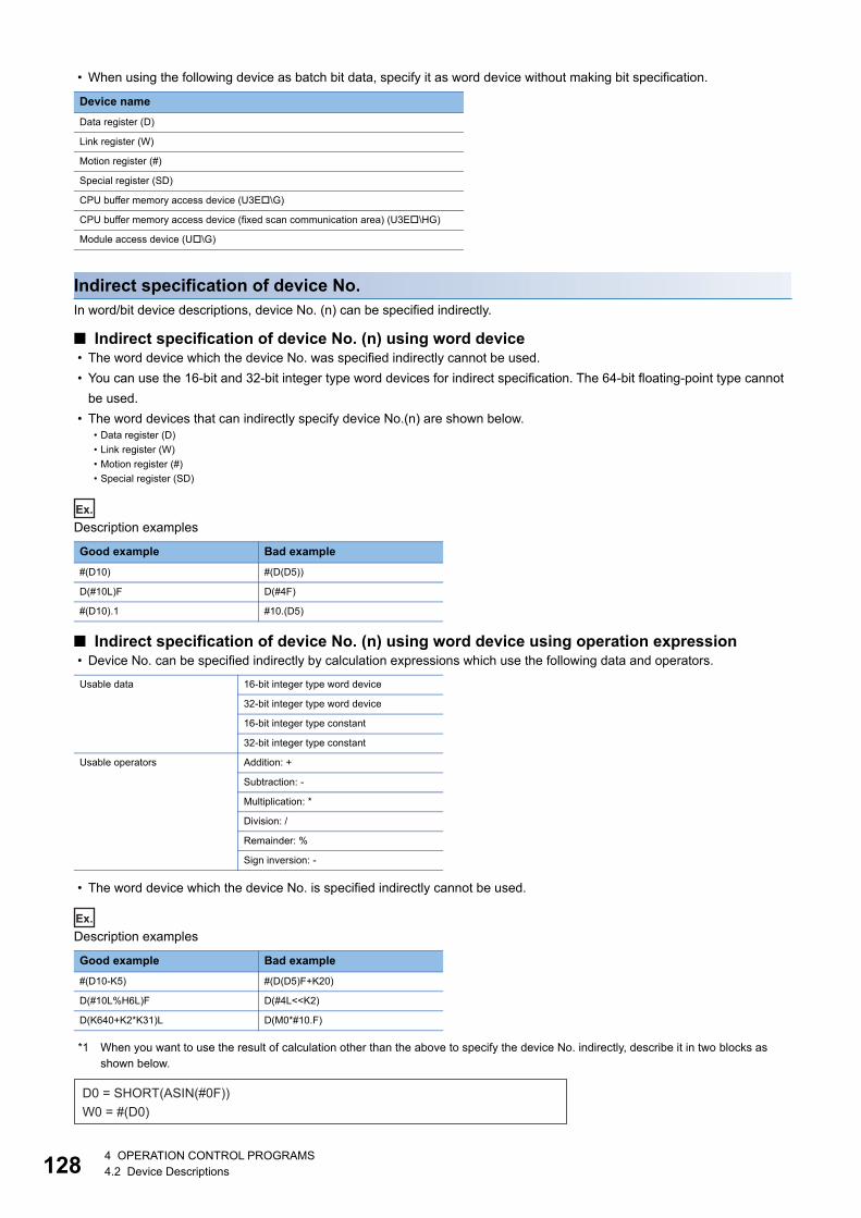
12
• When using the following device as batch bit data, specify it as word device without making bit specification.
Indirect specification of device No.In word/bit device descriptions, device No. (n) can be specified indirectly.
■ Indirect specification of device No. (n) using word device • The word device which the device No. was specified indirectly cannot be used.
• You can use the 16-bit and 32-bit integer type word devices for indirect specification. The 64-bit floating-point type cannot
be used.
• The word devices that can indirectly specify device No.(n) are shown below.
Ex.
Description examples
■ Indirect specification of device No. (n) using word device using operation expression • Device No. can be specified indirectly by calculation expressions which use the following data and operators.
• The word device which the device No. is specified indirectly cannot be used.
Ex.
Description examples
*1 When you want to use the result of calculation other than the above to specify the device No. indirectly, describe it in two blocks as shown below.
Device name
Data register (D)
Link register (W)
Motion register (#)
Special register (SD)
CPU buffer memory access device (U3E\G)
CPU buffer memory access device (fixed scan communication area) (U3E\HG)
Module access device (U\G)
• Data register (D)
• Link register (W)
• Motion register (#)
• Special register (SD)
Good example Bad example
#(D10) #(D(D5))
D(#10L)F D(#4F)
#(D10).1 #10.(D5)
Usable data 16-bit integer type word device
32-bit integer type word device
16-bit integer type constant
32-bit integer type constant
Usable operators Addition: +
Subtraction: -
Multiplication: *
Division: /
Remainder: %
Sign inversion: -
Good example Bad example
#(D10-K5) #(D(D5)F+K20)
D(#10L%H6L)F D(#4L<<K2)
D(K640+K2*K31)L D(M0*#10.F)
D0 = SHORT(ASIN(#0F))W0 = #(D0)
84 OPERATION CONTROL PROGRAMS4.2 Device Descriptions

4
4.3 Constant DescriptionsThe constant descriptions of the 16-bit integer type, 32-bit integer type and 64-bit floating-point type are shown below.
• The 32-bit integer type is ended by L and the 64-bit floating-point type is provided with a decimal point and exponent part
(E) to denote their data types explicitly.
• The constant without the data type is regarded as the applicable minimum type.
• The constant in decimal representation is headed by K and the one in hexadecimal representation by H. K can be omitted.
• The 64-bit floating-point type cannot be represented in hexadecimal.
Representation 16-bit integer type 32-bit integer type 64-bit floating-point type
Decimal representation K-32768 to K32767 K-2147483648L to K2147483647L K-1.79E+308 to K-2.23E-308,
K0.0,
K2.23E-308 to K1.79E+308
Hexadecimal representation H0000 to HFFFF H00000000L to HFFFFFFFFL
4 OPERATION CONTROL PROGRAMS4.3 Constant Descriptions 129

13
4.4 LabelsA label is a variable consisting of a specified character string used in I/O data or internal processing.
Using labels in programming enables creation of programs without being aware of devices.
For this reason, a program using labels can be reused easily even in a system having a different module configuration.
Types
LabelsA label provides the same data within a single project. It can be used in all programs in the project.
The settings of a label include a label name, and data type.
By opening labels, they can be referenced from GOT, and can be used for monitoring and accessing data.
When programming with labels for input and output devices, assign the labels to the devices directly.
The following types of labels are available.
• System label
A system label is a label that provides the same data in all projects compatible with iQ Works. It can be
referenced from the GOT and the CPU modules on other stations, and used for monitoring and accessing
data. For details, refer to the following.
Let's start iQ Works
Data typesThe data types of a label are classified according to the bit length, processing method, and value range.
The types are shown below.
Primitive data typeThe following table lists the data types included in the primitive data type.
When using double word [unsigned]/bit string [32 bits], double word [signed], double-precision real number
data types, use an even number device.
Data type Description Value range Bit length
Bit BOOL Represents the alternative status, such as ON or OFF. 0 (FALSE), 1 (TRUE) 1 bit
Word [unsigned]/bit string [16 bits] WORD 16-bit array. 0 to 65535 16 bits
Double word [unsigned]/bit string [32 bits] DWORD 32-bit array. 0 to 4294967295 32 bits
Word [signed] INT Positive and negative integer values. -32768 to 32767 16 bits
Double word [signed] DINT Positive and negative double-precision integer values. -2147483648 to 2147483647 32 bits
Double-precision real number LREAL Numerical values of decimal places (double-precision
real number values).
K-1.79E+308 to K-2.23E-308,
K0.0,
K2.23E-308 to K1.79E+308
64 bits
04 OPERATION CONTROL PROGRAMS4.4 Labels

4
ArraysAn array represents a consecutive aggregation of same data type labels as a single name.
Primitive data types and structures can be defined as arrays.
The maxim number of array elements varies depending on the data type.
Defining arrays
■ Array elementsWhen an array is defined, the number of elements, or the length of array, must be determined.
■ Definition formatThe following table lists definition format examples up to three dimensions.
The range from the array start value to the array end value is the number of elements.
How to use arraysTo use an array, add an index enclosed by "[ ]" after each label name to identify individual labels.
An array with two or more dimensions should be represented with indexes delimited by a comma (,) in "[ ]".
The following table lists the types of indexes that can be specified for arrays.
Number of array dimensions
Format Remarks
One dimension Array of primitive data type/structure name (array start value..array end value) • Refer to primitive data type for
details on primitive data type
(Page 130 Primitive data
type)
• Refer to structures for details
on structures (Page 132
Structures)
[Definition example] Bit (0..2)
Two dimensions Array of primitive data type/structure name (array start value..array end value, array start
value..array end value)
[Definition example] Bit (0..2, 0..1)
Three dimensions Array of primitive data type/structure name (array start value..array end value, array start
value..array endvalue, array start value..array end value)
[Definition example] Bit (0..2, 0..1, 0..3)
Type Specification example Remarks
Constant bLabel1[0] An integer can be specified.
Device bLabel1[D0] A word device, double-word device, decimal constant, or hexadecimal constant can be specified. (Data
register(D), Link register(W), and Motion register(#) devices can be used.)
Index
[0]bLabel1
Label name
[1]
�
[n]
IndexLabel name
bLabel2 [0,0]
[1,0]
�
[m,0]
[0,1]
[1,1]
� �
[0,n]
�
�
��
�� [m,n]
Two-dimensional arrayOne-dimensional array
bLabel1 [0] bLabel2 [0,3]
Label name Index
4 OPERATION CONTROL PROGRAMS4.4 Labels 131

13
• The data storage location becomes dynamic by specifying a device for the array index. This enables arrays
to be used in a program that executes loop processing. The following is a program example that
consecutively stores "1234" in the "uLabel4" array.
• When the device number of a device assigned to a label exceeds 32767, specify a 32 bit integer device to
the index.
(Example)
Assigning "D32000" to the start device of label array "uLabel4", and also accessing D32768 onwards by
specifying "#0" to the index of the array.
Precautions
■ When an event task is usedWhen a device is specified for the array index, the operation is performed with a combination of multiple instructions. For this
reason, if an interrupt occurs during operation of the label defined as an array, data inconsistency may occur producing an
unintended operation result.
To prevent data inconsistency, perform one of the following.
• Do not change the device being used as the index in a normal task during the event task.
• Use the DI/EI instructions that disable/enable event tasks before and after using the label defined in the array.
■ Array elementsWhen accessing the element defined in an array, access it within the range of the number of elements.
If a constant out of the range defined for the array index is specified, an error will occur when converting the Motion SFC
program.
If the array index is specified with data other than a constant, an error will not occur when converting the Motion SFC program.
The processing will be performed by accessing another device.
StructuresA structure is a data type containing one or more labels and can be used in all programs.
Members (labels) included in a structure can be defined even when their data types are different.
Creating structuresTo create a structure, first define the structure, and then define members in the structure.
FOR #0 = K0 TO K9 STEP K1 uLabel4[#0] = K1234NEXT
uLabel4[#0L]
Member (Label1)
Member (Label2)
Member (Label3)
Member (Label4)
Structure
24 OPERATION CONTROL PROGRAMS4.4 Labels
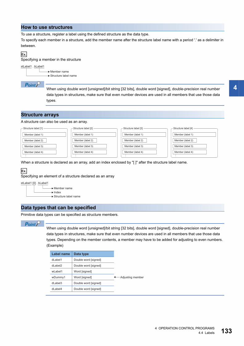
4
How to use structuresTo use a structure, register a label using the defined structure as the data type.
To specify each member in a structure, add the member name after the structure label name with a period '.' as a delimiter in
between.
Ex.
Specifying a member in the structure
When using double word [unsigned]/bit string [32 bits], double word [signed], double-precision real number
data types in structures, make sure that even number devices are used in all members that use those data
types.
Structure arraysA structure can also be used as an array.
When a structure is declared as an array, add an index enclosed by "[ ]" after the structure label name.
Ex.
Specifying an element of a structure declared as an array
Data types that can be specifiedPrimitive data types can be specified as structure members.
When using double word [unsigned]/bit string [32 bits], double word [signed], double-precision real number
data types in structures, make sure that even number devices are used in all members that use those data
types. Depending on the member contents, a member may have to be added for adjusting to even numbers.
(Example)
stLabel1 . bLabel1
Structure label nameMember name
Member (label 1)
Member (label 2)
Member (label 3)
Member (label 4)
Member (label 1)
Member (label 2)
Member (label 3)
Member (label 4)
Member (label 1)
Member (label 2)
Member (label 3)
Member (label 4)
Member (label 1)
Member (label 2)
Member (label 3)
Member (label 4)
Structure label [1] Structure label [2] Structure label [3] Structure label [4]
stLabel1 [0] . bLabel1
Member nameIndexStructure label name
dLabel1
Label name Data type
Double word [signed]
Double word [signed]
Word [signed]
Word [signed]
Double word [signed]
Double word [signed]
dLabel2
wLabel1
wDummy1 Adjusting member
dLabel3
dLabel4
4 OPERATION CONTROL PROGRAMS4.4 Labels 133

13
Precautions
Restrictions on naming labelsThe following restrictions apply when naming labels.
• Start the name with a character. Numbers or an underline (_) cannot be used at the beginning of label names.
• Reserved words cannot be used.
For details on the reserved words, refer to the following.
Help of MT Developer2
44 OPERATION CONTROL PROGRAMS4.4 Labels
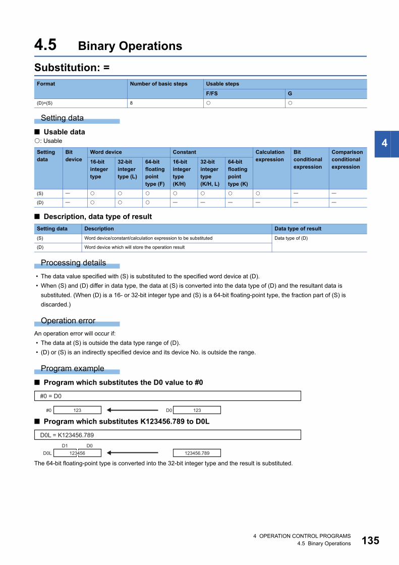
4
4.5 Binary Operations
Substitution: =
Setting data
■ Usable data: Usable
■ Description, data type of result
Processing details
• The data value specified with (S) is substituted to the specified word device at (D).
• When (S) and (D) differ in data type, the data at (S) is converted into the data type of (D) and the resultant data is
substituted. (When (D) is a 16- or 32-bit integer type and (S) is a 64-bit floating-point type, the fraction part of (S) is
discarded.)
Operation error
An operation error will occur if:
• The data at (S) is outside the data type range of (D).
• (D) or (S) is an indirectly specified device and its device No. is outside the range.
Program example
■ Program which substitutes the D0 value to #0
■ Program which substitutes K123456.789 to D0L
The 64-bit floating-point type is converted into the 32-bit integer type and the result is substituted.
Format Number of basic steps Usable steps
F/FS G
(D)=(S) 8
Setting data
Bit device
Word device Constant Calculation expression
Bit conditional expression
Comparison conditional expression
16-bit integer type
32-bit integer type (L)
64-bit floating point type (F)
16-bit integer type(K/H)
32-bit integer type(K/H, L)
64-bit floating point type (K)
(S)
(D)
Setting data Description Data type of result
(S) Word device/constant/calculation expression to be substituted Data type of (D)
(D) Word device which will store the operation result
#0 = D0
123#0 123D0
D0L = K123456.789
123456D0L 123456.789D0D1
4 OPERATION CONTROL PROGRAMS4.5 Binary Operations 135

13
■ Program which substitutes the result of adding K123 and #0 to W0
W0 = K123 + #0
579W0
123
456
+
#0
64 OPERATION CONTROL PROGRAMS4.5 Binary Operations

4
Addition: +
Setting data
■ Usable data: Usable
■ Description, data type of result
Processing details
• The data specified with (S2) is added to the data specified with (S1).
• When (S1) and (S2) differ in data type, the data of the smaller data type is converted into that of the greater type before
operation is performed.
Operation error
An operation error will occur if:
• (S1) or (S2) is an indirectly specified device and its device No. is outside the range.
Program example
■ Program which substitutes the result of adding K123 and #0 to W0
■ Program which substitutes the result of adding #0F and #10 to D0L
The 64-bit floating-point type data are used for addition, and the result is converted into the 32-bit integer type and then
substituted.
Format Number of basic steps Usable steps
F/FS G
(S1)+(S2) 7
Setting data
Bit device
Word device Constant Calculation expression
Bit conditional expression
Comparison conditional expression
16-bit integer type
32-bit integer type (L)
64-bit floating point type (F)
16-bit integer type(K/H)
32-bit integer type(K/H, L)
64-bit floating point type (K)
(S1)
(S2)
Setting data Description Data type of result
(S1) Augend data Data type of (S1) or (S2) which is greater
(S2) Addend data
W0 = K123 + #0
579W0
123
456#0
+
12468D0D1
#2 #1 #0#3
D0L = #0F + #10
D0L
123
+
#10
#0F 12345.78912468.789
4 OPERATION CONTROL PROGRAMS4.5 Binary Operations 137

13
Subtraction: -
Setting data
■ Usable data: Usable
■ Description, data type of result
Processing details
• The data specified with (S2) is subtracted from the data specified with (S1).
• When (S1) and (S2) differ in data type, the data of the smaller data type is converted into that of the greater type before
operation is performed.
Operation error
An operation error will occur if:
• (S1) or (S2) is an indirectly specified device and its device No. is outside the range.
Program example
■ Program which substitutes the result of subtracting #0 from K123 to W0
■ Program which substitutes the result of subtracting #10 from #0F to D0L
The 64-bit floating-point type data are used for subtraction, and the result is converted into the 32-bit integer type and then
substituted.
Format Number of basic steps Usable steps
F/FS G
(S1)-(S2) 7
Setting data
Bit device
Word device Constant Calculation expression
Bit conditional expression
Comparison conditional expression
16-bit integer type
32-bit integer type (L)
64-bit floating point type (F)
16-bit integer type(K/H)
32-bit integer type(K/H, L)
64-bit floating point type (K)
(S1)
(S2)
Setting data Description Data type of result
(S1) Minuend data Data type of (S1) or (S2) which is greater
(S2) Subtracted data
W0 = K123 - #0
-333W0
123
456
-
#0
12222D0D1
#2 #1 #0#3
D0L = #0F - #10
D0L
123
-
#10
#0F 12345.78912222.789
84 OPERATION CONTROL PROGRAMS4.5 Binary Operations
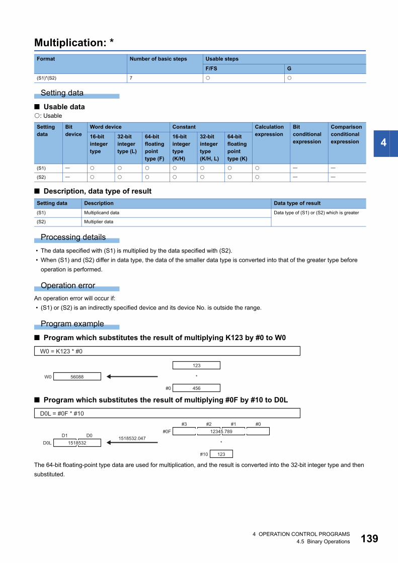
4
Multiplication: *
Setting data
■ Usable data: Usable
■ Description, data type of result
Processing details
• The data specified with (S1) is multiplied by the data specified with (S2).
• When (S1) and (S2) differ in data type, the data of the smaller data type is converted into that of the greater type before
operation is performed.
Operation error
An operation error will occur if:
• (S1) or (S2) is an indirectly specified device and its device No. is outside the range.
Program example
■ Program which substitutes the result of multiplying K123 by #0 to W0
■ Program which substitutes the result of multiplying #0F by #10 to D0L
The 64-bit floating-point type data are used for multiplication, and the result is converted into the 32-bit integer type and then
substituted.
Format Number of basic steps Usable steps
F/FS G
(S1)*(S2) 7
Setting data
Bit device
Word device Constant Calculation expression
Bit conditional expression
Comparison conditional expression
16-bit integer type
32-bit integer type (L)
64-bit floating point type (F)
16-bit integer type(K/H)
32-bit integer type(K/H, L)
64-bit floating point type (K)
(S1)
(S2)
Setting data Description Data type of result
(S1) Multiplicand data Data type of (S1) or (S2) which is greater
(S2) Multiplier data
W0 = K123 * #0
56088W0
123
456
*
#0
1518532D0D1
#2 #1 #0#3
D0L = #0F * #10
D0L
123
*
#10
#0F 12345.7891518532.047
4 OPERATION CONTROL PROGRAMS4.5 Binary Operations 139

14
Division: /
Setting data
■ Usable data: Usable
■ Description, data type of result
Processing details
• The data specified with (S1) is divided by the data specified with (S2) to find a quotient.
• When (S1) and (S2) differ in data type, the data of the smaller data type is converted into that of the greater type before
operation is performed.
Operation error
An operation error will occur if:
• (S2) is 0.
• (S1) or (S2) is an indirectly specified device and its device No. is outside the range.
Program example
■ Program which divides K456 by #0 and substitutes a quotient to W0
■ Program which divides #0F by #10 and substitutes a quotient to D0L
The 64-bit floating-point type data are used for division, and the quotient is converted into the 32-bit integer type and then
substituted.
Format Number of basic steps Usable steps
F/FS G
(S1)/(S2) 7
Setting data
Bit device
Word device Constant Calculation expression
Bit conditional expression
Comparison conditional expression
16-bit integer type
32-bit integer type (L)
64-bit floating point type (F)
16-bit integer type(K/H)
32-bit integer type(K/H, L)
64-bit floating point type (K)
(S1)
(S2)
Setting data Description Data type of result
(S1) Dividend data Data type of (S1) or (S2) which is greater
(S2) Divisor data
W0 = K456 / #0
3W0
456
123
/
#0
100D0D1
#2 #1 #0#3
D0L = #0F * #10
D0L
123
/
#10
#0F 12345.789100.3722683
04 OPERATION CONTROL PROGRAMS4.5 Binary Operations

4
Remainder: %
Setting data
■ Usable data: Usable
■ Description, data type of result
Processing details
• The data specified with (S1) is divided by the data specified with (S2) to find a remainder.
• When (S1) and (S2) differ in data type, the data of the smaller data type is converted into that of the greater type before
operation is performed.
Operation error
An operation error will occur if:
• (S2) is 0.
• (S1) or (S2) is an indirectly specified device and its device No. is outside the range.
Program example
■ Program which divides K456 by #0 and substitutes a remainder to W0
Format Number of basic steps Usable steps
F/FS G
(S1)%(S2) 7
Setting data
Bit device
Word device Constant Calculation expression
Bit conditional expression
Comparison conditional expression
16-bit integer type
32-bit integer type (L)
64-bit floating point type (F)
16-bit integer type(K/H)
32-bit integer type(K/H, L)
64-bit floating point type (K)
(S1)
(S2)
Setting data Description Data type of result
(S1) Dividend data Data type (integer type) of (S1) or (S2)
which is greater (Integer type)(S2) Divisor data
W0 = K456 % #0
87W0
456
123
%
#0
4 OPERATION CONTROL PROGRAMS4.5 Binary Operations 141

14
4.6 Bit Operations
Bit inversion (Complement): ~
Setting data
■ Usable data: Usable
■ Description, data type of result
Processing details
The bit inverted value of the data specified with (S) is found.
Operation error
An operation error will occur if:
• (S) is an indirectly specified device and its device No. is outside the range.
Program example
■ Program which finds the bit inverted value of #0 and substitutes the value to D0
Format Number of basic steps Usable steps
F/FS G
~(S) 4
Setting data
Bit device
Word device Constant Calculation expression
Bit conditional expression
Comparison conditional expression
16-bit integer type
32-bit integer type (L)
64-bit floating point type (F)
16-bit integer type(K/H)
32-bit integer type(K/H, L)
64-bit floating point type (K)
(S)
Setting data Description Data type of result
(S) Data whose bits will be inverted Data type of (S) (Integer type)
D0 = ~#0
D0 1 1 0 1 1 0 1 0 1 1 0 0 1 0 1 1b0b15
#0 0 0 1 0 0 1 0 1 0 0 1 1 0 1 0 0b0b15
24 OPERATION CONTROL PROGRAMS4.6 Bit Operations

4
Bit logical AND: &
Setting data
■ Usable data: Usable
■ Description, data type of result
Processing details
• The bit-by-bit logical product of the data specified with (S1) and the data specified with (S2) is found.
• When (S1) and (S2) differ in data type, the data of the smaller data type is converted into that of the greater type before
operation is performed. At this time, note that signed data is converted.
Operation error
An operation error will occur if:
• (S1) or (S2) is an indirectly specified device and its device No. is outside the range.
Program example
■ Program which ANDs #0 and #1 and substitutes the result to D0
Format Number of basic steps Usable steps
F/FS G
(S1)&(S2) 7
Setting data
Bit device
Word device Constant Calculation expression
Bit conditional expression
Comparison conditional expression
16-bit integer type
32-bit integer type (L)
64-bit floating point type (F)
16-bit integer type(K/H)
32-bit integer type(K/H, L)
64-bit floating point type (K)
(S1)
(S2)
Setting data Description Data type of result
(S1) Data which will be ANDed bit-by-bit Data type of (S1) or (S2) which is greater
(Integer type)(S2)
D0 = #0 & #1
D0b0b15
#0
0 0 1 0 0 0 0 1 0 0 1 0 0 1 0 0
0 0 1 0 0 1 0 1 0 0 1 1 0 1 0 0b0b15
#1 0 0 1 0 1 0 0 1 0 0 1 0 0 1 0 0b0b15
&
4 OPERATION CONTROL PROGRAMS4.6 Bit Operations 143

14
Bit logical OR: |
Setting data
■ Usable data: Usable
■ Description, data type of result
Processing details
• The bit-by-bit logical add of the data specified with (S1) and the data specified with (S2) is found.
• When (S1) and (S2) differ in data type, the data of the smaller data type is converted into that of the greater type before
operation is performed. At this time, note that signed data is converted.
Operation error
An operation error will occur if:
• (S1) or (S2) is an indirectly specified device and its device No. is outside the range.
Program example
■ Program which ORs #0 and #1 and substitutes the result to D0
Format Number of basic steps Usable steps
F/FS G
(S1) | (S2) 7
Setting data
Bit device
Word device Constant Calculation expression
Bit conditional expression
Comparison conditional expression
16-bit integer type
32-bit integer type (L)
64-bit floating point type (F)
16-bit integer type(K/H)
32-bit integer type(K/H, L)
64-bit floating point type (K)
(S1)
(S2)
Setting data Description Data type of result
(S1) Data which will be ORed bit-by-bit Data type of (S1) or (S2) which is greater
(Integer type)(S2)
D0 = #0 | #1
D0b0b15
#0
0 0 1 0 1 1 0 1 0 0 1 1 0 1 0 0
0 0 1 0 0 1 0 1 0 0 1 1 0 1 0 0b0b15
#1 0 0 1 0 1 0 0 1 0 0 1 0 0 1 0 0b0b15
|
44 OPERATION CONTROL PROGRAMS4.6 Bit Operations
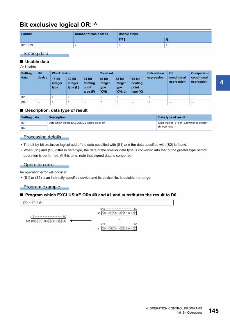
4
Bit exclusive logical OR: ^
Setting data
■ Usable data: Usable
■ Description, data type of result
Processing details
• The bit-by-bit exclusive logical add of the data specified with (S1) and the data specified with (S2) is found.
• When (S1) and (S2) differ in data type, the data of the smaller data type is converted into that of the greater type before
operation is performed. At this time, note that signed data is converted.
Operation error
An operation error will occur if:
• (S1) or (S2) is an indirectly specified device and its device No. is outside the range.
Program example
■ Program which EXCLUSIVE ORs #0 and #1 and substitutes the result to D0
Format Number of basic steps Usable steps
F/FS G
(S1)^(S2) 7
Setting data
Bit device
Word device Constant Calculation expression
Bit conditional expression
Comparison conditional expression
16-bit integer type
32-bit integer type (L)
64-bit floating point type (F)
16-bit integer type(K/H)
32-bit integer type(K/H, L)
64-bit floating point type (K)
(S1)
(S2)
Setting data Description Data type of result
(S1) Data which will be EXCLUSIVE ORed bit-by-bit Data type of (S1) or (S2) which is greater
(Integer type)(S2)
D0 = #0 ^ #1
D0b0b15
#0
0 0 0 0 1 1 0 0 0 0 0 1 0 0 0 0
0 0 1 0 0 1 0 1 0 0 1 1 0 1 0 0b0b15
#1 0 0 1 0 1 0 0 1 0 0 1 0 0 1 0 0b0b15
^
4 OPERATION CONTROL PROGRAMS4.6 Bit Operations 145

14
Bit right shift: >>
Setting data
■ Usable data: Usable
■ Description, data type of result
Processing details
• The data specified with (S1) is shifted to the right by the number of times specified with (S2).
• If the most significant bit of (S1) is 1, 1 enters the most significant bit of the right shift result. If the most significant bit of (S1)
is 0, 0 enters the most significant bit of the right shift result.
• When (S1) is a 16-bit integer type and (S2) is a negative number or not less than 16, the result is 0.
• When (S1) is a 32-bit integer type and (S2) is a negative number or not less than 32, the result is 0.
Operation error
An operation error will occur if:
• (S1) or (S2) is an indirectly specified device and its device No. is outside the range.
Program example
■ Program which shifts #0 two bit positions to the right and substitutes the result to D0
Format Number of basic steps Usable steps
F/FS G
(S1) >> (S2) 7
Setting data
Bit device
Word device Constant Calculation expression
Bit conditional expression
Comparison conditional expression
16-bit integer type
32-bit integer type (L)
64-bit floating point type (F)
16-bit integer type(K/H)
32-bit integer type(K/H, L)
64-bit floating point type (K)
(S1)
(S2)
Setting data Description Data type of result
(S1) Data to be right-shifted Data type of (S1) (Integer type)
(S2) Number of right shifts
D0 = #0 >> K2
D0b0b15
#0 0 0 1 0 0 1 0 1 0 0 1 1 0 1 0 00 0 0 0 1 0 0 1 0 1 0 0 1 1 0 1b0b15
64 OPERATION CONTROL PROGRAMS4.6 Bit Operations

4
Bit left shift: <<
Setting data
■ Usable data: Usable
■ Description, data type of result
Processing details
• The data specified with (S1) is shifted to the left by the number of times specified with (S2).
• 0 enters the least significant bit of the left shift result.
• When (S1) is a 16-bit integer type and (S2) is a negative number or not less than 16, the result is 0.
• When (S1) is a 32-bit integer type and (S2) is a negative number or not less than 32, the result is 0.
Operation error
An operation error will occur if:
• (S1) or (S2) is an indirectly specified device and its device No. is outside the range.
Program example
■ Program which shifts #0 one bit position to the left and substitutes the result to D0
Format Number of basic steps Usable steps
F/FS G
(S1) << (S2) 7
Setting data
Bit device
Word device Constant Calculation expression
Bit conditional expression
Comparison conditional expression
16-bit integer type
32-bit integer type (L)
64-bit floating point type (F)
16-bit integer type(K/H)
32-bit integer type(K/H, L)
64-bit floating point type (K)
(S1)
(S2)
Setting data Description Data type of result
(S1) Data to be left-shifted Data type of (S1) (Integer type)
(S2) Number of left shifts
D0 = #0 << K1
D0b0b15
#0 0 0 1 0 0 1 0 1 0 0 1 1 0 1 0 00 1 0 0 1 0 1 0 0 1 1 0 1 0 0 0b0b15
4 OPERATION CONTROL PROGRAMS4.6 Bit Operations 147

14
Sign inversion (Complement of 2): -
Setting data
■ Usable data: Usable
■ Description, data type of result
Processing details
The sign-inverted value of the data specified with (S) is found.
Operation error
An operation error will occur if:
• (S) is an indirectly specified device and its device No. is outside the range.
Program example
■ Program which substitutes the sign-inverted value of #0 to D0
Format Number of basic steps Usable steps
F/FS G
-(S) 4
Setting data
Bit device
Word device Constant Calculation expression
Bit conditional expression
Comparison conditional expression
16-bit integer type
32-bit integer type (L)
64-bit floating point type (F)
16-bit integer type(K/H)
32-bit integer type(K/H, L)
64-bit floating point type (K)
(S)
Setting data Description Data type of result
(S) Data whose sign will be inverted Data type of (S)
D0 = -#0
-123D0 123#0
84 OPERATION CONTROL PROGRAMS4.6 Bit Operations
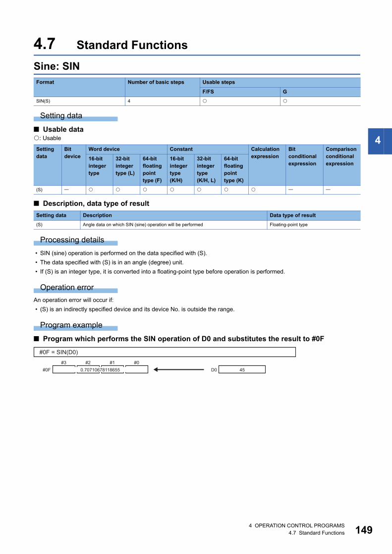
4
4.7 Standard Functions
Sine: SIN
Setting data
■ Usable data: Usable
■ Description, data type of result
Processing details
• SIN (sine) operation is performed on the data specified with (S).
• The data specified with (S) is in an angle (degree) unit.
• If (S) is an integer type, it is converted into a floating-point type before operation is performed.
Operation error
An operation error will occur if:
• (S) is an indirectly specified device and its device No. is outside the range.
Program example
■ Program which performs the SIN operation of D0 and substitutes the result to #0F
Format Number of basic steps Usable steps
F/FS G
SIN(S) 4
Setting data
Bit device
Word device Constant Calculation expression
Bit conditional expression
Comparison conditional expression
16-bit integer type
32-bit integer type (L)
64-bit floating point type (F)
16-bit integer type(K/H)
32-bit integer type(K/H, L)
64-bit floating point type (K)
(S)
Setting data Description Data type of result
(S) Angle data on which SIN (sine) operation will be performed Floating-point type
#0F = SIN(D0)
45D0#2 #1 #0#3
#0F 0.70710678118655
4 OPERATION CONTROL PROGRAMS4.7 Standard Functions 149

15
Cosine: COS
Setting data
■ Usable data: Usable
■ Description, data type of result
Processing details
• COS (cosine) operation is performed on the data specified with (S).
• The data specified with (S) is in an angle (degree) unit.
• If (S) is an integer type, it is converted into a floating-point type before operation is performed.
Operation error
An operation error will occur if:
• (S) is an indirectly specified device and its device No. is outside the range.
Program example
■ Program which performs the COS operation of D0 and substitutes the result to #0F
Format Number of basic steps Usable steps
F/FS G
COS(S) 4
Setting data
Bit device
Word device Constant Calculation expression
Bit conditional expression
Comparison conditional expression
16-bit integer type
32-bit integer type (L)
64-bit floating point type (F)
16-bit integer type(K/H)
32-bit integer type(K/H, L)
64-bit floating point type (K)
(S)
Setting data Description Data type of result
(S) Angle data on which COS (cosine) operation will be performed Floating-point type
#0F = COS(D0)
60D0#2 #1 #0#3
#0F 0.5
04 OPERATION CONTROL PROGRAMS4.7 Standard Functions

4
Tangent: TAN
Setting data
■ Usable data: Usable
■ Description, data type of result
Processing details
• TAN (tangent) operation is performed on the data specified with (S).
• The data specified with (S) is in an angle (degree) unit.
• If (S) is an integer type, it is converted into a floating-point type before operation is performed.
Operation error
An operation error will occur if:
• (S) is an indirectly specified device and its device No. is outside the range.
• (S) is 90 + (180*n). ("n" is an integer)
Program example
■ Program which performs the TAN operation of D0 and substitutes the result to #0F
Format Number of basic steps Usable steps
F/FS G
TAN(S) 4
Setting data
Bit device
Word device Constant Calculation expression
Bit conditional expression
Comparison conditional expression
16-bit integer type
32-bit integer type (L)
64-bit floating point type (F)
16-bit integer type(K/H)
32-bit integer type(K/H, L)
64-bit floating point type (K)
(S)
Setting data Description Data type of result
(S) Angle data on which TAN (tangent) operation will be performed Floating-point type
#0F = TAN(D0)
30D0#2 #1 #0#3
#0F 0.57735026918963
4 OPERATION CONTROL PROGRAMS4.7 Standard Functions 151

15
Arcsine: ASIN
Setting data
■ Usable data: Usable
■ Description, data type of result
Processing details
• SIN-1 (arcsine) operation is performed on the SIN value data specified with (S) to find an angle.
• The SIN value specified with (S) must be within the range -1.0 to 1.0.
• The operation result is in an angle (degree) unit.
• If (S) is an integer type, it is converted into a floating-point type before operation is performed.
Operation error
An operation error will occur if:
• (S) is outside the range -1.0 to 1.0.
• (S) is an indirectly specified device and its device number is outside the range.
Program example
■ Program which performs the SIN-1 (arcsine) operation of D0 and substitutes the result to #0F
Format Number of basic steps Usable steps
F/FS G
ASIN(S) 4
Setting data
Bit device
Word device Constant Calculation expression
Bit conditional expression
Comparison conditional expression
16-bit integer type
32-bit integer type (L)
64-bit floating point type (F)
16-bit integer type(K/H)
32-bit integer type(K/H, L)
64-bit floating point type (K)
(S)
Setting data Description Data type of result
(S) SIN value data on which SIN-1 (arcsine) operation will be performed Floating-point type
#0F = ASIN(D0)
1D0#2 #1 #0#3
#0F 90.0
24 OPERATION CONTROL PROGRAMS4.7 Standard Functions

4
Arccosine: ACOS
Setting data
■ Usable data: Usable
■ Description, data type of result
Processing details
• COS-1 (arccosine) operation is performed on the COS value data specified with (S) to find an angle.
• The COS value specified with (S) must be within the range -1.0 to 1.0.
• The operation result is in an angle (degree) unit.
• If (S) is an integer type, it is converted into a floating-point type before operation is performed.
Operation error
An operation error will occur if:
• (S) is outside the range -1.0 to 1.0.
• (S) is an indirectly specified device and its device No. is outside the range.
Program example
■ Program which performs the COS-1 (arccosine) operation of D0F and substitutes the result to #0F
Format Number of basic steps Usable steps
F/FS G
ACOS(S) 4
Setting data
Bit device
Word device Constant Calculation expression
Bit conditional expression
Comparison conditional expression
16-bit integer type
32-bit integer type (L)
64-bit floating point type (F)
16-bit integer type(K/H)
32-bit integer type(K/H, L)
64-bit floating point type (K)
(S)
Setting data Description Data type of result
(S) COS value data on which COS-1 (arccosine) operation will be performed Floating-point type
#0F = ACOS(D0F)
#2 #1 #0#3#0F 60.0
D2 D1 D0D3D0F 0.5
4 OPERATION CONTROL PROGRAMS4.7 Standard Functions 153

15
Arctangent: ATAN
Setting data
■ Usable data: Usable
■ Description, data type of result
Processing details
• TAN-1 (arctangent) operation is performed on the TAN value data specified with (S) to find an angle.
• The operation result is in an angle (degree) unit.
• If (S) is an integer type, it is converted into a floating-point type before operation is performed.
Operation error
An operation error will occur if:
• (S) is an indirectly specified device and its device No. is outside the range.
Program example
■ Program which performs the TAN-1 (arctangent) operation of D0F and substitutes the result to #0F
Format Number of basic steps Usable steps
F/FS G
ATAN(S) 4
Setting data
Bit device
Word device Constant Calculation expression
Bit conditional expression
Comparison conditional expression
16-bit integer type
32-bit integer type (L)
64-bit floating point type (F)
16-bit integer type(K/H)
32-bit integer type(K/H, L)
64-bit floating point type (K)
(S)
Setting data Description Data type of result
(S) TAN value data on which TAN-1 (arctangent) operation will be performed Floating-point type
#0F = ATAN(D0F)
#2 #1 #0#3#0F 45.0
D2 D1 D0D3D0F 1.0
44 OPERATION CONTROL PROGRAMS4.7 Standard Functions

4
Square root: SQRT
Setting data
■ Usable data: Usable
■ Description, data type of result
Processing details
• The square root of the data specified with (S) is found.
• Only a positive number may be specified with (S). (Operation cannot be performed with a negative number.)
• If (S) is an integer type, it is converted into a floating-point type before operation is performed.
Operation error
An operation error will occur if:
• (S) is a negative number.
• (S) is an indirectly specified device and its device No. is outside the range.
Program example
■ Program which finds the square root of D0F and substitutes the result to #0F
Format Number of basic steps Usable steps
F/FS G
SQRT(S) 4
Setting data
Bit device
Word device Constant Calculation expression
Bit conditional expression
Comparison conditional expression
16-bit integer type
32-bit integer type (L)
64-bit floating point type (F)
16-bit integer type(K/H)
32-bit integer type(K/H, L)
64-bit floating point type (K)
(S)
Setting data Description Data type of result
(S) Data on which square root operation will be performed Floating-point type
#0F = SQRT(D0F)
#2 #1 #0#3#0F 3.0
D2 D1 D0D3D0F 9.0
4 OPERATION CONTROL PROGRAMS4.7 Standard Functions 155

15
Natural logarithm: LN
Setting data
■ Usable data: Usable
■ Description, data type of result
Processing details
• The base e natural logarithm of the data specified with (S) is found.
• Only a positive number may be specified with (S). (Operation cannot be performed with a negative number.)
• If (S) is an integer type, it is converted into a floating-point type before operation is performed.
Operation error
An operation error will occur if:
• (S) is 0 or a negative number.
• (S) is an indirectly specified device and its device No. is outside the range.
Program example
■ Program which finds the natural logarithm of D0F and substitutes the result to #0F
Format Number of basic steps Usable steps
F/FS G
LN(S) 4
Setting data
Bit device
Word device Constant Calculation expression
Bit conditional expression
Comparison conditional expression
16-bit integer type
32-bit integer type (L)
64-bit floating point type (F)
16-bit integer type(K/H)
32-bit integer type(K/H, L)
64-bit floating point type (K)
(S)
Setting data Description Data type of result
(S) Data on which natural logarithm operation will be performed Floating-point type
#0F = LN(D0F)
#2 #1 #0#3#0F 2.3025850929940
D2 D1 D0D3D0F 10.0
64 OPERATION CONTROL PROGRAMS4.7 Standard Functions

4
Exponential operation: EXP
Setting data
■ Usable data: Usable
■ Description, data type of result
Processing details
• Exponential operation is performed on the base e data specified with (S).
• If (S) is an integer type, it is converted into a floating-point type before operation is performed.
Operation error
An operation error will occur if:
• (S) is an indirectly specified device and its device No. is outside the range.
Program example
■ Program which performs exponential operation of D0F and substitutes the result to #0F
Format Number of basic steps Usable steps
F/FS G
EXP(S) 4
Setting data
Bit device
Word device Constant Calculation expression
Bit conditional expression
Comparison conditional expression
16-bit integer type
32-bit integer type (L)
64-bit floating point type (F)
16-bit integer type(K/H)
32-bit integer type(K/H, L)
64-bit floating point type (K)
(S)
Setting data Description Data type of result
(S) Data on which exponential operation will be performed Floating-point type
#0F = EXP(D0F)
#2 #1 #0#3#0F 442413.39200892
D2 D1 D0D3D0F 13.0
4 OPERATION CONTROL PROGRAMS4.7 Standard Functions 157

15
Absolute value: ABS
Setting data
■ Usable data: Usable
■ Description, data type of result
Processing details
The absolute value of the data specified with (S) is found.
Operation error
An operation error will occur if:
• (S) is 16-bit integer type and other than -32767 to 32767.
• (S) is 32-bit integer type and other than -2147483647 to 2147483647.
• (S) is an indirectly specified device and its device No. is outside the range.
Program example
■ Program which finds the absolute value of D0F and substitutes the result to #0F
Format Number of basic steps Usable steps
F/FS G
ABS(S) 4
Setting data
Bit device
Word device Constant Calculation expression
Bit conditional expression
Comparison conditional expression
16-bit integer type
32-bit integer type (L)
64-bit floating point type (F)
16-bit integer type(K/H)
32-bit integer type(K/H, L)
64-bit floating point type (K)
(S)
Setting data Description Data type of result
(S) Data on which absolute value conversion will be performed Data type of (S)
#0F = ABS(D0F)
#2 #1 #0#3#0F 33.0
D2 D1 D0D3D0F -33.0
84 OPERATION CONTROL PROGRAMS4.7 Standard Functions

4
Round-off: RND
Setting data
■ Usable data: Usable
■ Description, data type of result
Processing details
• The rounded-off fractional portion value of the data specified with (S) is found.
• If (S) is a negative number, the absolute value of (S) is found and its fractional portion is rounded off and signed.
• If (S) is an integer type, its value is returned unchanged, with no conversion processing performed.
Operation error
An operation error will occur if:
• (S) is an indirectly specified device and its device No. is outside the range.
Program example
■ Program which finds the rounded-off fractional portion value of D0F and substitutes the result to #0F
■ Program which finds the rounded-off fractional portion value of D4F and substitutes the result to #0F (when D4F is a negative number)
Format Number of basic steps Usable steps
F/FS G
RND(S) 4
Setting data
Bit device
Word device Constant Calculation expression
Bit conditional expression
Comparison conditional expression
16-bit integer type
32-bit integer type (L)
64-bit floating point type (F)
16-bit integer type(K/H)
32-bit integer type(K/H, L)
64-bit floating point type (K)
(S)
Setting data Description Data type of result
(S) Data whose fractional portion will be rounded off Data type of (S)
#0F = RND(D0F)
#2 #1 #0#3#0F 34.0
D2 D1 D0D3D0F 33.54
#0F = RND(D4F)
#2 #1 #0#3#0F -33.0
D6 D5 D4D7D4F -33.44
4 OPERATION CONTROL PROGRAMS4.7 Standard Functions 159

16
Round-down: FIX
Setting data
■ Usable data: Usable
■ Description, data type of result
Processing details
• The largest integer not greater than the data specified with (S) is found.
• If the (S) value is positive, the absolute value will be smaller, and if it is negative, the absolute value will be greater.
• If (S) is an integer type, its value is returned unchanged, with no conversion processing performed.
Operation error
An operation error will occur if:
• (S) is an indirectly specified device and its device No. is outside the range.
Program example
■ Program which finds the rounded-down fractional portion value of D0F and substitutes the result to #0F
■ Program which finds the rounded-down fractional portion value of D4F and substitutes the result to #0F (when D4F is a negative number)
Format Number of basic steps Usable steps
F/FS G
FIX(S) 4
Setting data
Bit device
Word device Constant Calculation expression
Bit conditional expression
Comparison conditional expression
16-bit integer type
32-bit integer type (L)
64-bit floating point type (F)
16-bit integer type(K/H)
32-bit integer type(K/H, L)
64-bit floating point type (K)
(S)
Setting data Description Data type of result
(S) Data whose fractional portion will be rounded down Data type of (S)
#0F = FIX(D0F)
#2 #1 #0#3#0F 33.0
D2 D1 D0D3D0F 33.54
#0F = FIX(D4F)
#2 #1 #0#3#0F -34.0
D6 D5 D4D7D4F -33.54
04 OPERATION CONTROL PROGRAMS4.7 Standard Functions

4
Round-up: FUP
Setting data
■ Usable data: Usable
■ Description, data type of result
Processing details
• The smallest integer not less than the data specified with (S) is found.
• If the (S) value is positive, the absolute value will be greater, and if it is negative, the absolute value will be smaller.
• If (S) is an integer type, its value is returned unchanged, with no conversion processing performed.
Operation error
An operation error will occur if:
• (S) is an indirectly specified device and its device No. is outside the range.
Program example
■ Program which finds the rounded-up fractional portion value of D0F and substitutes the result to #0F
■ Program which finds the rounded-up fractional portion value of D4F and substitutes the result to #0F (when D4F is a negative number)
Format Number of basic steps Usable steps
F/FS G
FUP(S) 4
Setting data
Bit device
Word device Constant Calculation expression
Bit conditional expression
Comparison conditional expression
16-bit integer type
32-bit integer type (L)
64-bit floating point type (F)
16-bit integer type(K/H)
32-bit integer type(K/H, L)
64-bit floating point type (K)
(S)
Setting data Description Data type of result
(S) Data whose fractional portion will be rounded up Data type of (S)
#0F = FUP(D0F)
#2 #1 #0#3#0F 34.0
D2 D1 D0D3D0F 33.54
#0F = FUP(D4F)
#2 #1 #0#3#0F -33.0
D6 D5 D4D7D4F -33.54
4 OPERATION CONTROL PROGRAMS4.7 Standard Functions 161

16
BCD -> BIN conversion: BIN
Setting data
■ Usable data: Usable
■ Description, data type of result
Processing details
• The BCD data specified with (S) is converted into BIN data.
• If (S) is a 16-bit integer type, the data range is 0 to 9999.
• If (S) is a 32-bit integer type, the data range is 0 to 99999999.
Operation error
An operation error will occur if:
• A value other than 0 to 9 is in any digit of (S).
• (S) is an indirectly specified device and its device No. is outside the range.
Program example
■ Program which converts the BCD data of D0 into BIN data and substitutes the result to #0
Format Number of basic steps Usable steps
F/FS G
BIN(S) 4
Setting data
Bit device
Word device Constant Calculation expression
Bit conditional expression
Comparison conditional expression
16-bit integer type
32-bit integer type (L)
64-bit floating point type (F)
16-bit integer type(K/H)
32-bit integer type(K/H, L)
64-bit floating point type (K)
(S)
Setting data Description Data type of result
(S) BCD data which will be converted into BIN data Data type of (S) (Integer type)
#0 = BIN(D0)
#0 0 0 1 0 0 1 1 1 0 0 0 0 1 1 1 1b0b15
D0 1 0 0 1 1 0 0 1 1 0 0 1 1 0 0 1b0b15
BCD 9999BIN 9999
HundredsTens
UnitsThousands
24 OPERATION CONTROL PROGRAMS4.7 Standard Functions

4
BIN -> BCD conversion: BCD
Setting data
■ Usable data: Usable
■ Description, data type of result
Processing details
• The BIN data specified with (S) is converted into BCD data.
• If (S) is a 16-bit integer type, the data range is 0 to 9999.
• If (S) is a 32-bit integer type, the data range is 0 to 99999999.
Operation error
An operation error will occur if:
• The data is other than 0 to 9999 when (S) is a 16-bit integer type.
• The data is other than 0 to 99999999 when (S) is a 32-bit integer type.
• (S) is an indirectly specified device and its device No. is outside the range.
Program example
■ Program which converts the BIN data of D0 into BCD data and substitutes the result to #0
Format Number of basic steps Usable steps
F/FS G
BCD(S) 4
Setting data
Bit device
Word device Constant Calculation expression
Bit conditional expression
Comparison conditional expression
16-bit integer type
32-bit integer type (L)
64-bit floating point type (F)
16-bit integer type(K/H)
32-bit integer type(K/H, L)
64-bit floating point type (K)
(S)
Setting data Description Data type of result
(S) BIN data which will be converted into BCD data Data type of (S) (Integer type)
#0 = BCD(D0)
D0 0 0 1 0 0 1 1 1 0 0 0 0 1 1 1 1b0b15
BIN 9999
#0 1 0 0 1 1 0 0 1 1 0 0 1 1 0 0 1b0b15
BCD 9999
HundredsTens
UnitsThousands
4 OPERATION CONTROL PROGRAMS4.7 Standard Functions 163

16
4.8 Data Control
16-bit integer type scaling: SCL
Setting data
■ Usable data: Usable
■ Description, data type of result
Processing details
• 16-bit integer type scaling calculates the output value from the set input value based on the scaling conversion data where
a maximum of 4000 points data ((X0, Y0) to (XN-1, YN-1), N: the number of points) are defined. Set the point data
corresponding to the input value in ascending order. (Positive conversion: X0 < X1 <.....< XN-1, Inverse conversion: Y0 < Y1
<.....< YN-1)
• The method for output value calculation is either positive conversion (Input value: point X, Output value: point Y) or inverse
conversion (Input value: point Y, Output value: point X) and is specified with (S1). Each of the calculation methods is as
follows.
Format Number of basic steps Usable steps
F/FS G
SCL(S1), (S2), (S3), (D) 15
Setting data
Bit device
Word device Constant Calculation expression
Bit conditional expression
Comparison conditional expression
16-bit integer type
32-bit integer type (L)
64-bit floating point type (F)
16-bit integer type(K/H)
32-bit integer type(K/H, L)
64-bit floating point type (K)
(S1)
(S2)
(S3)
(D)
Setting data Description Data type of result
(S1) Data which specifies the search/conversion method
0: Positive conversion by sequential search
1: Inverse conversion by sequential search
2: Positive conversion by binary search
3: Inverse conversion by binary search
(S2) Input value for positive/inverse conversion
(S3) Start device No. which stores the scaling conversion data
(D) Device No. which stores the conversion result
44 OPERATION CONTROL PROGRAMS4.8 Data Control

4
■ When the input value is between two points of scaling conversion dataThe output value is calculated from the nearest two points of the input value.
N: Number of points
■ When the input value is not between two points of scaling conversion dataThe output value is calculated from the first or last two points of scaling conversion data.
N: Number of points
When the input value is outside the range of scaling conversion data or calculation result of output value is
outside the range of -32768 to 32767, an operation error will occur.
Positive conversion Inverse conversion
X0 X (Input value) XN-1 Y0 Y (Input value) YN-1
Positive conversion Inverse conversion
X (Input value) < X0 Y (Input value) < Y0
XN-1 < X (Input value) YN-1 < Y (Input value)
X(X0, Y0)
(Xi, Yi)(Xi+1, Yi+1)
(XN-1, YN-1)
Y
Input value: X
Output value: Y
Y=Yi+ ×(X-Xi)Xi+1-Xi
Yi+1-YiX=Xi+ ×(Y-Yi)
Yi+1-Yi
Xi+1-Xi
X(X0, Y0)
(Xi, Yi)
(Xi+1, Yi+1)
(XN-1, YN-1)
Y
Input value: Y
Output value: X
X(X0, Y0)
(X1, Y1)
Y
(Y<Y0)
Y=Y0+ ×(X-X0)X1-X0
Y1-Y0
Input value: X
Output value: Y
(X<X0)
X=X0+ ×(Y-Y0)Y1-Y0
X1-X0
X(X0, Y0)
(X1, Y1)
Y
Input value: Y
Output value: X
X
(XN-2, YN-2)
(XN-1, YN-1)
YY=YN-1+ ×(X-XN-1)
YN-1-YN-2
XN-1-XN-2
(YN-1<Y)
Input value: X
Output value: Y
X
(XN-2, YN-2)
(XN-1, YN-1)
YX=XN-1+ ×(Y-YN-1)
XN-1-XN-2
YN-1-YN-2
(XN-1<X)
Input value: Y
Output value: X
4 OPERATION CONTROL PROGRAMS4.8 Data Control 165

16
• Conversion of the input value specified with (S2) is executed according to the search/conversion method specified with
(S1), using the scaling conversion data of device (S3) or later. The conversion result is stored in the device specified with
(D).
• In the scaling, point data used for output value calculation must be searched from the input value, and the search method is
specified with (S1). The search method is either sequential search or binary search, and the features are shown below.
Specify the search method according to the intended use.
• The device No. specified with (S3) should be an even number. Set the point data in the specified device as follows.
Set the point data corresponding to the input value in ascending order. (Positive conversion: X0 < X1 <.....<
XN-1, Inverse conversion: Y0 < Y1 <.....< YN-1)
• When the conversion result to be stored in the device specified with (D) is not an integer value, its fractional portion is
rounded down.
Operation error
An operation error will occur, and the conversion of input value will not be executed if:
• (S1) is set to other than 0 to 3.
• (S3) is not an even-numbered device.
• The number of points at the point table specified with (S3) is outside the range of 2 to 4000.
• Point table specified with (S3) is outside the device range.
• In sequential search ((S1) is 0 or 1.), the point corresponding to the input value (Positive conversion: X0 to XN-1, Inverse
conversion: Y0 to YN-1) is not in ascending order.
• The conversion result is outside the range of -32768 to 32767.
Search method
Search times when the number of points is 4000
Processing time Precaution
Sequential
search
1 to 4000 times 0.003 to 0.809 [ms]
Since the data is searched in order from the head in
sequential search, the maximum processing time
increases in proportion to the number of points.
During search processing, whether the point data
corresponding to the input value is in ascending order can
be checked. If the input value is not in ascending order, an
operation error will occur.
Binary
search
12 times 0.006 [ms]
Binary search requires relatively short search time since
the processing time does not increase in proportion to the
number of points.
During search processing, point data required for the
binary search are only referred to. If the data is not in
ascending order, the calculation result of output value
could be unexpected one since all of the point data
corresponding to the input value cannot be confirmed.
Offset Name Description Range
+0 The number of points (N) Set the number of points for the scaling conversion data. 2 to 4000
+1 Unusable Set 0. 0
+2 Point 0 X0 Set the point data of (X0, Y0) to (XN-1, YN-1) so that the device No. is in consecutive order. -32768 to 32767
+3 Y0
+4 Point 1 X1
+5 Y1
+6 Point 2 X2
+7 Y2
+(2N) Point (N-1) XN-1
+(2N+1) YN-1
64 OPERATION CONTROL PROGRAMS4.8 Data Control
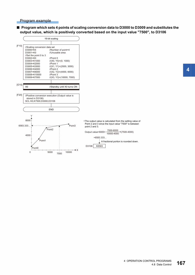
4
Program example
■ Program which sets 4 points of scaling conversion data to D3000 to D3009 and substitutes the output value, which is positively converted based on the input value "7500", to D3106
The output value is calculated from the setting value ofPoint 2 and 3 since the input value "7500" is betweenpoint 2 and 3.
A fractional portion is rounded down.
Y
X0
16-bit scaling
END
//Scaling conversion data setD3000=K4 //Number of point=4D3001=K0 //Unusable area//Set the point 0 to 3 D3002=K0 //Point 0D3003=K1000 //(X0, Y0)=(0, 1000) D3004=K2000 //Point 1D3005=K3000 //(X1, Y1)=(2000, 3000)D3006=K4000 //Point 2D3007=K6000 //(X2, Y2)=(4000, 6000)D3008=K10000 //Point 3D3009=K7000 //(X3, Y3)=(10000, 7000)
X0 //Standby until X0 turns ON
[F10]
[G10]
//Positive conversion execution (Output value is stored in D3106)SCL K0,K7500,D3000,D3106
[F20]
5000 7500
Point0
10000
4000
8000
6583.333…
Point1
Point2Point3
=6583.333...
Output value=6000+ ×(7500-4000)7000-600010000-4000
D3106 K6583
4 OPERATION CONTROL PROGRAMS4.8 Data Control 167

16
32-bit integer type scaling: DSCL
Setting data
■ Usable data: Usable
■ Description, data type of result
Processing details
• 32-bit integer type scaling calculates the output value from the set input value based on the scaling conversion data where
a maximum of 2000 points data ((X0, Y0) to (XN-1, YN-1), N: the number of points) are defined. The point data corresponding
to the input value should be set in ascending order. (Positive conversion: X0 < X1 <.....< XN-1, Inverse conversion: Y0 < Y1
<.....< YN-1)
• The calculation method for output value is the same as 16-bit integer type scaling. (Page 165 When the input value is
between two points of scaling conversion data, Page 165 When the input value is not between two points of scaling
conversion data)
When the input value is outside the scaling conversion data or calculation result of output value is outside the
range of -2147483648 to 2147483647, an operation error will occur.
Format Number of basic steps Usable steps
F/FS G
DSCL(S1), (S2), (S3), (D) 15
Setting data
Bit device
Word device Constant Calculation expression
Bit conditional expression
Comparison conditional expression
16-bit integer type
32-bit integer type (L)
64-bit floating point type (F)
16-bit integer type(K/H)
32-bit integer type(K/H, L)
64-bit floating point type (K)
(S1)
(S2)
(S3)
(D)
Setting data Description Data type of result
(S1) Data which specifies the search/conversion method
0: Positive conversion by sequential search
1: Inverse conversion by sequential search
2: Positive conversion by binary search
3: Inverse conversion by binary search
(S2) Input value for positive/inverse conversion
(S3) Start device No. which stores the scaling conversion data
(D) Device No. which stores the conversion result
84 OPERATION CONTROL PROGRAMS4.8 Data Control

4
• Conversion of the input value specified with (S2) is executed according to the search/conversion method specified with
(S1), using the scaling conversion data of device (S3) or later. The conversion result is stored in the device specified with
(D).
• The setting method of (S1) is the same as 16-bit integer type scaling. (Page 164 16-bit integer type scaling: SCL)
• The device No. specified with (S3) should be an even number. Set the point data in the specified device as follows.
Set the point data corresponding to the input value in ascending order. (Positive conversion: X0 < X1 <.....<
XN-1, Inverse conversion: Y0 < Y1 <.....< YN-1)
• When the conversion result to be stored in the device specified with (D) is not an integer value, its fractional portion is
rounded down.
Operation error
An operation error will occur, and the conversion of input value will not be executed if:
• (S1) is set to other than 0 to 3.
• (S2), (S3), and (D) are not even-numbered devices.
• The number of points at the point table specified with (S3) is outside the range of 2 to 2000.
• Point table specified with (S3) is outside the device range.
• In sequential search ((S1) is 0 or 1.), the point corresponding to the input value (Positive conversion: X0 to XN-1, Inverse
conversion: Y0 to YN-1) is not in ascending order.
• The conversion result is outside the range of -2147483648 to 2147483647.
Offset Name Description Range
+0 Number of points (N) Set the number of points for the scaling conversion data. 2 to 2000
+1 Unusable Set 0. 0
+2 Point 0 X0 Set the point data of (X0, Y0) to (XN-1, YN-1) so that the device No. is in consecutive order. -2147483648
to
2147483647+3
+4 Y0
+5
+6 Point 1 X1
+7
+8 Y1
+9
+10 Point 2 X2
+11
+12 Y2
+13
+(4N-2) Point (N-1) XN-1
+(4N-1)
+(4N) YN-1
+(4N+1)
4 OPERATION CONTROL PROGRAMS4.8 Data Control 169

17
Program example
■ Program which sets 4 points of scaling conversion data to D3000 to D3017 and substitutes the output value, which is positively converted based on the input value "-65000", to D3106L.
32-bit scaling
END
//Scaling conversion data setD3000=K4 //Number of point=4D3001=K0 //Unusable area//Set the point 0 to 3D3002L=K-100000L //Point 0 D3004L=K-70000L //(X0, Y0)=(-100000, -70000) D3006L=K-40000L //Point 1D3008L=K-60000L //(X1, Y1)=(-40000, -60000)D3010L=K-20000L //Point 2D3012L=K-30000L //(X2, Y2)=(-20000, -30000)D3014L=K0L //Point 3D3016L=K-10000 //(X3, Y3)=(0, -10000)
X0 //Standby until X0 turns ON
[F10]
[G10]
//Positive conversion execution (Output value is stored in D3106L)DSCL K0,K-65000,D3000,D3106L
[F20]
=-64166.666...
Output value=-70000+ ×(-65000-(-100000))(-60000-(-70000))(-40000-(-100000))
A fractional portion is rounded down.
D3106 D3107K-64166
0
-40000
-80000
Y
-40000-80000
-65000
-64166.666…
XPoint3
Point2
Point1Point0
The output value is calculated from the setting value ofPoint 0 and 1 since the input value "-65000" is betweenPoint 0 and 1.
04 OPERATION CONTROL PROGRAMS4.8 Data Control

4
4.9 Type Conversions
Signed 16-bit integer value conversion: SHORT
Setting data
■ Usable data: Usable
■ Description, data type of result
Processing details
• The data specified with (S) is converted into a signed 16-bit integer value.
• The data range of (S) is -32768 to 32767.
• When (S) is a 64-bit floating-point type, its fractional portion is rounded down before conversion is made.
• If (S) is a 16-bit integer type, its value is returned unchanged, with no conversion processing performed.
Operation error
An operation error will occur if:
• The (S) data is outside the range -32768 to 32767.
• (S) is an indirectly specified device and its device No. is outside the range.
Program example
■ Program which converts the data of D0L into a signed 16-bit integer value and substitutes the result to #0
Format Number of basic steps Usable steps
F/FS G
SHORT(S) 4
Setting data
Bit device
Word device Constant Calculation expression
Bit conditional expression
Comparison conditional expression
16-bit integer type
32-bit integer type (L)
64-bit floating point type (F)
16-bit integer type(K/H)
32-bit integer type(K/H, L)
64-bit floating point type (K)
(S)
Setting data Description Data type of result
(S) Data which will be converted into signed 16-bit integer value 16-bit integer type
#0 = SHORT(D0L)
K-30000LD0D1
D0LK-30000(HFFFF8AD0)(H8AD0)
#0
4 OPERATION CONTROL PROGRAMS4.9 Type Conversions 171

17
Unsigned 16-bit integer value conversion: USHORT
Setting data
■ Usable data: Usable
■ Description, data type of result
Processing details
• The data specified with (S) is converted into an unsigned 16-bit integer value.
• The data range of (S) is 0 to 65535.
• When (S) is a 64-bit floating-point type, its fractional portion is rounded down before conversion is made.
• If (S) is a 16-bit integer type, its value is returned unchanged, with no conversion processing performed.
Operation error
An operation error will occur if:
• The (S) data is outside the range 0 to 65535.
• (S) is an indirectly specified device and its device No. is outside the range.
Program example
■ Program which converts the data of D0L into an unsigned 16-bit integer value and substitutes the result to #0
Format Number of basic steps Usable steps
F/FS G
USHORT(S) 4
Setting data
Bit device
Word device Constant Calculation expression
Bit conditional expression
Comparison conditional expression
16-bit integer type
32-bit integer type (L)
64-bit floating point type (F)
16-bit integer type(K/H)
32-bit integer type(K/H, L)
64-bit floating point type (K)
(S)
Setting data Description Data type of result
(S) Data which will be converted into unsigned 16-bit integer value 16-bit integer type
#0 = USHORT(D0L)
K60000LD0D1
D0LK-5536(H0000EA60)(HEA60)
Unsigned value is K60000
#0
24 OPERATION CONTROL PROGRAMS4.9 Type Conversions

4
It is converted into a large data type to operate the binary operations with a different data type. Therefore,
USHORT does not become valid. The target binary operations are shown below.
• Addition (+)
• Subtraction (-)
• Multiplication (*)
• Division (/)
• Remainder (%)
• Bit logical AND (&)
• Bit logical OR (|)
• Bit exclusive logical OR (^)
(Example)
W0:F=#0F+USHORT(D0L)
USHORT does not become valid.
64-bit floating point type
4 OPERATION CONTROL PROGRAMS4.9 Type Conversions 173

17
Signed 32-bit integer value conversion: LONG
Setting data
■ Usable data: Usable
■ Description, data type of result
Processing details
• The data specified with (S) is converted into a signed 32-bit integer value.
• The data range of (S) is -2147483648 to 2147483647.
• When (S) is a 64-bit floating-point type, its fractional portion is rounded down before conversion is made.
• If (S) is a 32-bit integer type, its value is returned unchanged, with no conversion processing performed.
Operation error
An operation error will occur if:
• The (S) data is outside the range -2147483648 to 2147483647.
• (S) is an indirectly specified device and its device No. is outside the range.
Program example
■ Program which converts the data of D0 into a signed 32-bit integer value and substitutes the result to #0L
Format Number of basic steps Usable steps
F/FS G
LONG(S) 4
Setting data
Bit device
Word device Constant Calculation expression
Bit conditional expression
Comparison conditional expression
16-bit integer type
32-bit integer type (L)
64-bit floating point type (F)
16-bit integer type(K/H)
32-bit integer type(K/H, L)
64-bit floating point type (K)
(S)
Setting data Description Data type of result
(S) Data which will be converted into signed 32-bit integer value 32-bit integer type
#0L = LONG(D0)
K-1L#0#1
#0L(HFFFFFFFF)
K-1(HFFFF)
D0
44 OPERATION CONTROL PROGRAMS4.9 Type Conversions

4
Unsigned 32-bit integer value conversion: ULONG
Setting data
■ Usable Data: Usable
■ Description, data type of result
Processing details
• The data specified with (S) is converted into an unsigned 32-bit integer value.
• The data range of (S) is 0 to 4294967295.
• When (S) is a 64-bit floating-point type, its fractional portion is rounded down before conversion is made.
• If (S) is a 32-bit integer type, its value is returned unchanged, with no conversion processing performed.
Operation error
An operation error will occur if:
• The (S) data is outside the range 0 to 4294967295.
• (S) is an indirectly specified device and its device No. is outside the range.
Program example
■ Program which converts the data of D0 into an unsigned 32-bit integer value and substitutes the result to #0L
Format Number of basic steps Usable steps
F/FS G
ULONG(S) 4
Setting data
Bit device
Word device Constant Calculation expression
Bit conditional expression
Comparison conditional expression
16-bit integer type
32-bit integer type (L)
64-bit floating point type (F)
16-bit integer type(K/H)
32-bit integer type(K/H, L)
64-bit floating point type (K)
(S)
Setting data Description Data type of result
(S) Data which will be converted into unsigned 32-bit integer value 32-bit integer type
#0L = ULONG(D0)
K65535L#0#1
#0L(H0000FFFF)
K-1(HFFFF)
D0
Unsigned value is K65535
4 OPERATION CONTROL PROGRAMS4.9 Type Conversions 175

17
It is converted into a large data type to operate the binary operations with a different data type. Therefore,
ULONG does not become valid. The target binary operations are shown below.
• Addition (+)
• Subtraction (-)
• Multiplication (*)
• Division (/)
• Remainder (%)
• Bit logical AND (&)
• Bit logical OR (|)
• Bit exclusive logical OR (^)
(Example)
W0:F=#0F+ULONG(D0L)
ULONG does not become valid.
64-bit floating point type
64 OPERATION CONTROL PROGRAMS4.9 Type Conversions
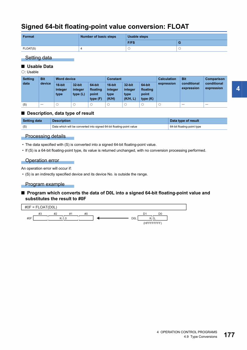
4
Signed 64-bit floating-point value conversion: FLOAT
Setting data
■ Usable Data: Usable
■ Description, data type of result
Processing details
• The data specified with (S) is converted into a signed 64-bit floating-point value.
• If (S) is a 64-bit floating-point type, its value is returned unchanged, with no conversion processing performed.
Operation error
An operation error will occur if:
• (S) is an indirectly specified device and its device No. is outside the range.
Program example
■ Program which converts the data of D0L into a signed 64-bit floating-point value and substitutes the result to #0F
Format Number of basic steps Usable steps
F/FS G
FLOAT(S) 4
Setting data
Bit device
Word device Constant Calculation expression
Bit conditional expression
Comparison conditional expression
16-bit integer type
32-bit integer type (L)
64-bit floating point type (F)
16-bit integer type(K/H)
32-bit integer type(K/H, L)
64-bit floating point type (K)
(S)
Setting data Description Data type of result
(S) Data which will be converted into signed 64-bit floating-point value 64-bit floating-point type
#0F = FLOAT(D0L)
#2 #1 #0#3#0F K-1.0 K-1L
(HFFFFFFFF)
D0D1D0L
4 OPERATION CONTROL PROGRAMS4.9 Type Conversions 177

17
Unsigned 64-bit floating-point value conversion: UFLOAT
Setting data
■ Usable Data: Usable
■ Description, data type of result
Processing details
• The data specified with (S) is converted into an unsigned 64-bit floating-point value.
• If (S) is a 64-bit floating-point type, its value is returned unchanged, with no conversion processing performed.
Operation error
An operation error will occur if:
• (S) is an indirectly specified device and its device No. is outside the range.
Program example
■ Program which converts the data of D0L into an unsigned 64-bit floating-point value and substitutes the result to #0F
Format Number of basic steps Usable steps
F/FS G
UFLOAT(S) 4
Setting data
Bit device
Word device Constant Calculation expression
Bit conditional expression
Comparison conditional expression
16-bit integer type
32-bit integer type (L)
64-bit floating point type (F)
16-bit integer type(K/H)
32-bit integer type(K/H, L)
64-bit floating point type (K)
(S)
Setting data Description Data type of result
(S) Data which will be converted into unsigned 64-bit floating-point value 64-bit floating-point type
#0F = UFLOAT(D0L)
#2 #1 #0#3#0F K4294967295.0 K-1L
(HFFFFFFFF)
D0D1D0L
Unsigned value is K4294967295
84 OPERATION CONTROL PROGRAMS4.9 Type Conversions

4
Floating-point value conversion 32-bit into 64-bit: DFLT
Setting data
■ Usable Data: Usable
*1 The data is handled as the 32-bit integer type on the program, but store the 32-bit floating-point data in the device.
■ Description, data type of result
Processing details
• The 32-bit floating-point (single precision real number) value stored in the device specified with (S) is converted into the 64-
bit floating-point (double precision real number) value. Convertible data ranges are shown below.
-3.40 1038 to -1.18 10-38, 0.0, 1.18 10-38 to 3.40 1038 (single precision real number)
• The 64-bit floating-point type is used as the data of floating-point type in the Motion SFC program. Use this instruction to
input the data of 32-bit floating-point type from the external devices.
Operation error
An operation error will occur if:
• The (S) data is not a valid 32-bit floating-point type.
Program example
■ Program which converts the 32-bit floating-point value data of D2000L into 64-bit floating-point value data and substitutes the result to #0F
Format Number of basic steps Usable steps
F/FS G
DFLT(S) 4
Setting data
Bit device
Word device Constant Calculation expression
Bit conditional expression
Comparison conditional expression
16-bit integer type
32-bit integer type (L)
64-bit floating point type (F)
16-bit integer type(K/H)
32-bit integer type(K/H, L)
64-bit floating point type (K)
(S) *1
Setting data Description Data type of result
(S) Data which will be converted into 64-bit floating-point value 64-bit floating-point type
#0F = DFLT(D2000L)
#2 #1 #0#3#0F K-1.0 K-1.0
D2000D2001D2000L
4 OPERATION CONTROL PROGRAMS4.9 Type Conversions 179

18
Floating-point value conversion 64-bit into 32-bit: SFLT
Setting data
■ Usable Data: Usable
■ Description, data type of result
Processing details
• The 64-bit floating-point (double precision real number) value stored in the device specified with (S) is converted into the
32-bit floating-point (single precision real number) value. Convertible data ranges are shown below.
-3.40 1038 to -1.18 10-38, 0.0, 1.18 10-38 to 3.40 1038 (single precision real number)
• The 64-bit floating-point type is used as the data of floating-point type in the Motion SFC program. Use this instruction to
output the data into the external devices that cannot use the 64-bit floating-point type.
The number of effective digits of 32-bit floating-point value data is approx. 7 digits. Data in the seven digits or
later of conversion result by SFLT instruction may not match the (S) data.
Operation error
An operation error will occur if:
• The (S) data is not a valid 64-bit floating-point type.
• The (S) data after convert is outside the range of 32 bit floating-point type.
Program example
■ Program which converts the 64-bit floating-point value data of #0F into 32-bit floating-point value data and substitutes the result to D2000L
Format Number of basic steps Usable steps
F/FS G
SFLT(S) 4
Setting data
Bit device
Word device Constant Calculation expression
Bit conditional expression
Comparison conditional expression
16-bit integer type
32-bit integer type (L)
64-bit floating point type (F)
16-bit integer type(K/H)
32-bit integer type(K/H, L)
64-bit floating point type (K)
(S)
Setting data Description Data type of result
(S) Data which will be converted into 32-bit floating-point value 32-bit floating-point type
D2000L = SFLT(#0F)
#2 #1 #0#3#0F K-1.0K-1.0
D2000D2001D2000L
04 OPERATION CONTROL PROGRAMS4.9 Type Conversions
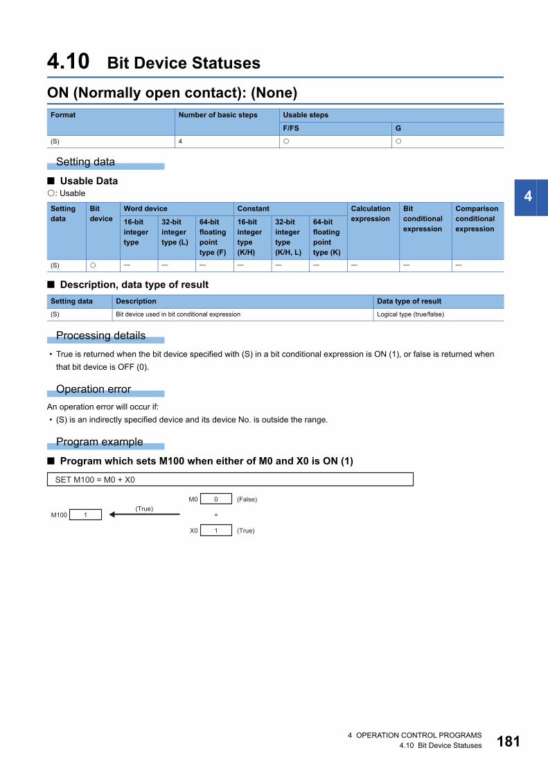
4
4.10 Bit Device Statuses
ON (Normally open contact): (None)
Setting data
■ Usable Data: Usable
■ Description, data type of result
Processing details
• True is returned when the bit device specified with (S) in a bit conditional expression is ON (1), or false is returned when
that bit device is OFF (0).
Operation error
An operation error will occur if:
• (S) is an indirectly specified device and its device No. is outside the range.
Program example
■ Program which sets M100 when either of M0 and X0 is ON (1)
Format Number of basic steps Usable steps
F/FS G
(S) 4
Setting data
Bit device
Word device Constant Calculation expression
Bit conditional expression
Comparison conditional expression
16-bit integer type
32-bit integer type (L)
64-bit floating point type (F)
16-bit integer type(K/H)
32-bit integer type(K/H, L)
64-bit floating point type (K)
(S)
Setting data Description Data type of result
(S) Bit device used in bit conditional expression Logical type (true/false)
SET M100 = M0 + X0
1M100
0 (False)
(True)
M0
1X0
+(True)
4 OPERATION CONTROL PROGRAMS4.10 Bit Device Statuses 181

18
OFF (Normally closed contact): !
Setting data
■ Usable Data: Usable
■ Description, data type of result
Processing details
• True is returned when the bit device specified with (S) in a bit conditional expression is OFF (0), or false is returned when
that bit device is ON (1).
Operation error
An operation error will occur if:
• (S) is an indirectly specified device and its device No. is outside the range.
Program example
■ Program which resets M100 when M0 is OFF (0)
Format Number of basic steps Usable steps
F/FS G
!(S) 4
Setting data
Bit device
Word device Constant Calculation expression
Bit conditional expression
Comparison conditional expression
16-bit integer type
32-bit integer type (L)
64-bit floating point type (F)
16-bit integer type(K/H)
32-bit integer type(K/H, L)
64-bit floating point type (K)
(S)
Setting data Description Data type of result
(S) Bit device used in bit conditional expression Logical type (true/false)
RST M100 = !M0
0 (True)!M00M100
24 OPERATION CONTROL PROGRAMS4.10 Bit Device Statuses

4
4.11 Bit Device Controls
Device set: SET
Setting data
■ Usable Data: Usable
■ Description, data type of result
Processing details
• If the data specified with (S) is true, the bit data specified with (D) is set.
• (S) can be omitted. At this time, the format is "SET(D)" and device set is made unconditionally.
• When this instruction is set as a transition condition in the last block of a transition program, whether the data specified with
(S) is true or false is returned as logical type data. In this case, (S) cannot be omitted.
Operation error
An operation error will occur if:
• (D) or (S) is an indirectly specified device and its device No. is outside the range.
Program example
■ Program which sets M100 when either of M0 and X0 is 1
■ Program which sets M100 when #0 is equal to D0
Format Number of basic steps Usable steps
F/FS G
SET(D)=(S) 8
Setting data
Bit device
Word device Constant Calculation expression
Bit conditional expression
Comparison conditional expression
16-bit integer type
32-bit integer type (L)
64-bit floating point type (F)
16-bit integer type(K/H)
32-bit integer type(K/H, L)
64-bit floating point type (K)
(D)
(S)
Setting data Description Data type of result
(D) Bit data for device set Bit logical type (true/false)
(S) Condition data which determines whether device set will be performed or not
SET M100 = M0 + X0
1M100
0
(True)
M0
1X0
+
SET M100 = #0 == D0
1M100
100
(True)
#0
100D0
==
4 OPERATION CONTROL PROGRAMS4.11 Bit Device Controls 183

18
■ Program which sets Y0 unconditionally
SET Y0
1Y0
44 OPERATION CONTROL PROGRAMS4.11 Bit Device Controls

4
Device reset: RST
Setting data
■ Usable Data: Usable
■ Description, data type of result
Processing details
• If the data specified with (S) is true, the bit data specified with (D) is reset.
• (S) can be omitted. At this time, the format is "RST(D)" and device reset is made unconditionally.
• When this instruction is set as a transition condition in the last block of a transition program, whether the data specified with
(S) is true or false is returned as logical type data. In this case, (S) cannot be omitted.
Operation error
An operation error will occur if:
• (D) or (S) is an indirectly specified device and its device No. is outside the range.
Program example
■ Program which resets M100 when either of M0 and X0 is 1
■ Program which resets M100 when #0 is equal to D0
■ Program which resets Y0 unconditionally
Format Number of basic steps Usable steps
F/FS G
RST(D)=(S) 8
Setting data
Bit device
Word device Constant Calculation expression
Bit conditional expression
Comparison conditional expression
16-bit integer type
32-bit integer type (L)
64-bit floating point type (F)
16-bit integer type(K/H)
32-bit integer type(K/H, L)
64-bit floating point type (K)
(D)
(S)
Setting data Description Data type of result
(D) Bit data for device reset Bit logical type (true/false)
(S) Condition data which determines whether device reset will be performed or not
RST M100 = M0 + X0
0M100
0
(True)
M0
1X0
+
RST M100 = #0 != D0
0M100
100
(True)
#0
200D0
!=
RST Y0
0Y0
4 OPERATION CONTROL PROGRAMS4.11 Bit Device Controls 185

18
Device output: DOUT
Setting data
■ Usable Data: Usable
■ Description, data type of result
Processing details
• The data specified with (S) is output to the bit data specified with (D).
• Specify a multiple of 16 as the device No. of the bit data specified with (D).
• If the type of (S) is a 16-bit integer type, 16 points of the (S) data, starting at the least significant bit, are output in order to
the bit devices headed by the one specified with (D).
• If the type of (S) is a 32-bit integer type, 32 points of the (S) data, starting at the least significant bit, are output in order to
the bit devices headed by the one specified with (D).
Operation error
An operation error will occur if:
• (D) or (S) is an indirectly specified device and its device No. is outside the range.
• (D) is an indirectly specified device and its device No. is not a multiple of 16.
Program example
■ Program which outputs the data of D0 to Y0-YF
Format Number of basic steps Usable steps
F/FS G
DOUT (D),(S) 8
Setting data
Bit device
Word device Constant Calculation expression
Bit conditional expression
Comparison conditional expression
16-bit integer type
32-bit integer type (L)
64-bit floating point type (F)
16-bit integer type(K/H)
32-bit integer type(K/H, L)
64-bit floating point type (K)
(D)
(S)
Setting data Description Data type of result
(D) Output destination bit data Batch bit
(S) Output source data
DOUT Y0,D0
Y0YFD0 0 0 1 0 0 1 1 1 0 0 0 0 1 1 1 10 0 1 0 0 1 1 1 0 0 0 0 1 1 1 1
b0b15
64 OPERATION CONTROL PROGRAMS4.11 Bit Device Controls

4
Device input: DIN
Setting data
■ Usable Data: Usable
■ Description, data type of result
Processing details
• The bit data specified with (S) is input to the data specified with (D).
• Specify a multiple of 16 as the device No. of the bit data specified with (S).
• If the type of (D) is a 16-bit integer type, 16 points of the (D) data, starting at the least significant bit, are input in order to the
bit devices headed by the one specified with (S).
• If the type of (D) is a 32-bit integer type, 32 points of the (D) data, starting at the least significant bit, are input in order to the
bit devices headed by the one specified with (S).
Operation error
An operation error will occur if:
• (D) or (S) is an indirectly specified device and its device No. is outside the range.
• (S) is an indirectly specified device and its device No. is not a multiple of 16.
Program example
■ Program which inputs the data of X0-XF to D0
Format Number of basic steps Usable steps
F/FS G
DIN (D),(S) 8
Setting data
Bit device
Word device Constant Calculation expression
Bit conditional expression
Comparison conditional expression
16-bit integer type
32-bit integer type (L)
64-bit floating point type (F)
16-bit integer type(K/H)
32-bit integer type(K/H, L)
64-bit floating point type (K)
(D)
(S)
Setting data Description Data type of result
(D) Input destination data Data type of (D) (Integer type)
(S) Input source bit data
DIN D0,X0
D0b0b15
0 0 1 0 0 1 1 1 0 0 0 0 1 1 1 10 0 1 0 0 1 1 1 0 0 0 0 1 1 1 1X0XF
4 OPERATION CONTROL PROGRAMS4.11 Bit Device Controls 187

18
Bit device output: OUT
Setting data
■ Usable Data: Usable
■ Description, data type of result
Processing details
• If the data specified with (S) is true, the bit data specified with (D) is set, and if the data specified with (S) is false, the bit
data specified with (D) is reset.
• When this instruction is set as a transition condition in the last block of a transient program, whether the data specified with
(S) is true or false is returned as logical type data.
• In this case, (S) cannot be omitted.
Operation error
An operation error will occur if:
• (D) or (S) is an indirectly specified device and its device No. is outside the range.
Program example
■ Program which sets M100 when M0 is ON (1) and program which resets M100 when M0 is OFF (0)
■ Program which sets M100 when M0 and M1 are both on and resets M100 except it
■ Program which sets M100 when D0 is equal to D2000 and resets M100 when D is not equal to D2000
Format Number of basic steps Usable steps
F/FS G
OUT(D)=(S) 8
Setting data
Bit device
Word device Constant Calculation expression
Bit conditional expression
Comparison conditional expression
16-bit integer type
32-bit integer type (L)
64-bit floating point type (F)
16-bit integer type(K/H)
32-bit integer type(K/H, L)
64-bit floating point type (K)
(D)
(S)
Setting data Description Data type of result
(D) Bit device for device output Bit logical type (true/false)
(S) Condition data which determines device output
OUT M100 = M0
OUT M100 = M0 * M1
OUT M100 = (D0 == D2000)
84 OPERATION CONTROL PROGRAMS4.11 Bit Device Controls

4
4.12 Logical Operations
Logical acknowledgement: (None)
Setting data
■ Usable Data: Usable
■ Description, data type of result
Processing details
• Whether the logical type data specified with (S) is true or false is returned unchanged. (Logical acknowledgement)
Operation error
An operation error will occur if:
• (S) is an indirectly specified device and its device No. is outside the range.
Program example
■ Program which sets M100 when either of M0 and X0 is ON (1)
Format Number of basic steps Usable steps
F/FS G
(S)
Setting data
Bit device
Word device Constant Calculation expression
Bit conditional expression
Comparison conditional expression
16-bit integer type
32-bit integer type (L)
64-bit floating point type (F)
16-bit integer type(K/H)
32-bit integer type(K/H, L)
64-bit floating point type (K)
(S)
Setting data Description Data type of result
(S) Data which will be logically acknowledged Logical type (true/false)
SET M100 = M0 + X0
1M100
0 (False)
(True)
M0
1X0
+(True)
4 OPERATION CONTROL PROGRAMS4.12 Logical Operations 189

19
Logical negation: !
Setting data
■ Usable Data: Usable
■ Description, data type of result
Processing details
• The data specified with (S) is logically negated.
Operation error
An operation error will occur if:
• (S) is an indirectly specified device and its device No. is outside the range.
Program example
■ Program which sets M100 when "either of M0 and X0 is not ON (1)" (when M0 and X0 are both OFF (0))
Format Number of basic steps Usable steps
F/FS G
!(S) 4
Setting data
Bit device
Word device Constant Calculation expression
Bit conditional expression
Comparison conditional expression
16-bit integer type
32-bit integer type (L)
64-bit floating point type (F)
16-bit integer type(K/H)
32-bit integer type(K/H, L)
64-bit floating point type (K)
(S)
Setting data Description Data type of result
(S) Data which will be logically negated Logical type (true/false)
Setting data Description Data type of result
(S) Data which will be logically negated Logical type (true/false)
SET M100 = !(M0 + X0)
1M100
0
(Flse)
(False)M0
0X0
+(True) ! (False)
04 OPERATION CONTROL PROGRAMS4.12 Logical Operations

4
Logical AND: *
Setting data
■ Usable Data: Usable
■ Description, data type of result
Processing details
• The data specified with (S1) and the data specified with (S2) are ANDed.
Operation error
An operation error will occur if:
• (S) is an indirectly specified device and its device No. is outside the range.
Program example
■ Program which sets M100 when M0 and X0 are both 1
Format Number of basic steps Usable steps
F/FS G
(S1)*(S2) 7
Setting data
Bit device
Word device Constant Calculation expression
Bit conditional expression
Comparison conditional expression
16-bit integer type
32-bit integer type (L)
64-bit floating point type (F)
16-bit integer type(K/H)
32-bit integer type(K/H, L)
64-bit floating point type (K)
(S1)
(S2)
Setting data Description Data type of result
(S1) Data which will be ANDed Logical type (true/false)
(S2)
SET M100 = M0 * X0
1M100
1
(True)
M0
1X0
*
4 OPERATION CONTROL PROGRAMS4.12 Logical Operations 191

19
Logical OR: +
Setting data
■ Usable Data: Usable
■ Description, data type of result
Processing details
• The data specified with (S1) and the data specified with (S2) are ORed.
Operation error
An operation error will occur if:
• (S1) or (S2) is an indirectly specified device and its device No. is outside the range.
Program example
■ Program which sets M100 when either of M0 and X0 is 1
Format Number of basic steps Usable steps
F/FS G
(S1)+(S2) 7
Setting data
Bit device
Word device Constant Calculation expression
Bit conditional expression
Comparison conditional expression
16-bit integer type
32-bit integer type (L)
64-bit floating point type (F)
16-bit integer type(K/H)
32-bit integer type(K/H, L)
64-bit floating point type (K)
(S1)
(S2)
Setting data Description Data type of result
(S1) Data which will be ORed Logical type (true/false)
(S2)
SET M100 = M0 + X0
1M100
0
(True)
M0
1X0
+
24 OPERATION CONTROL PROGRAMS4.12 Logical Operations

4
4.13 Comparison Operations
Equal to: ==
Setting data
■ Usable Data: Usable
■ Description, data type of result
Processing details
• The data specified with (S1) and the data specified with (S2) are compared, and the result is true if they are equal.
• When (S1) and (S2) differ in data type, the data of the smaller data type is converted into that of the greater type before
comparison is performed.
Operation error
An operation error will occur if:
• (S1) or (S2) is an indirectly specified device and its device No. is outside the range.
Program example
■ Program which compares whether #0 and D0 are equal or not
Format Number of basic steps Usable steps
F/FS G
(S1)==(S2) 7
Setting data
Bit device
Word device Constant Calculation expression
Bit conditional expression
Comparison conditional expression
16-bit integer type
32-bit integer type (L)
64-bit floating point type (F)
16-bit integer type(K/H)
32-bit integer type(K/H, L)
64-bit floating point type (K)
(S1)
(S2)
Setting data Description Data type of result
(S1) Data which will be compared Logical type (true/false)
(S2)
#0 == D0
(True)
100
100
==
D0
#0
4 OPERATION CONTROL PROGRAMS4.13 Comparison Operations 193

19
Not equal to: !=
Setting data
■ Usable Data: Usable
■ Description, data type of result
Processing details
• The data specified with (S1) and the data specified with (S2) are compared, and the result is true if they are not equal.
• When (S1) and (S2) differ in data type, the data of the smaller data type is converted into that of the greater type before
comparison is performed.
Operation error
An operation error will occur if:
• (S1) or (S2) is an indirectly specified device and its device No. is outside the range.
Program example
■ Program which compares whether #0 and D0 are unequal or not
Format Number of basic steps Usable steps
F/FS G
(S1)!=(S2) 7
Setting data
Bit device
Word device Constant Calculation expression
Bit conditional expression
Comparison conditional expression
16-bit integer type
32-bit integer type (L)
64-bit floating point type (F)
16-bit integer type(K/H)
32-bit integer type(K/H, L)
64-bit floating point type (K)
(S1)
(S2)
Setting data Description Data type of result
(S1) Data which will be compared Logical type (true/false)
(S2)
#0 != D0
(True)
100
20
!=
D0
#0
44 OPERATION CONTROL PROGRAMS4.13 Comparison Operations
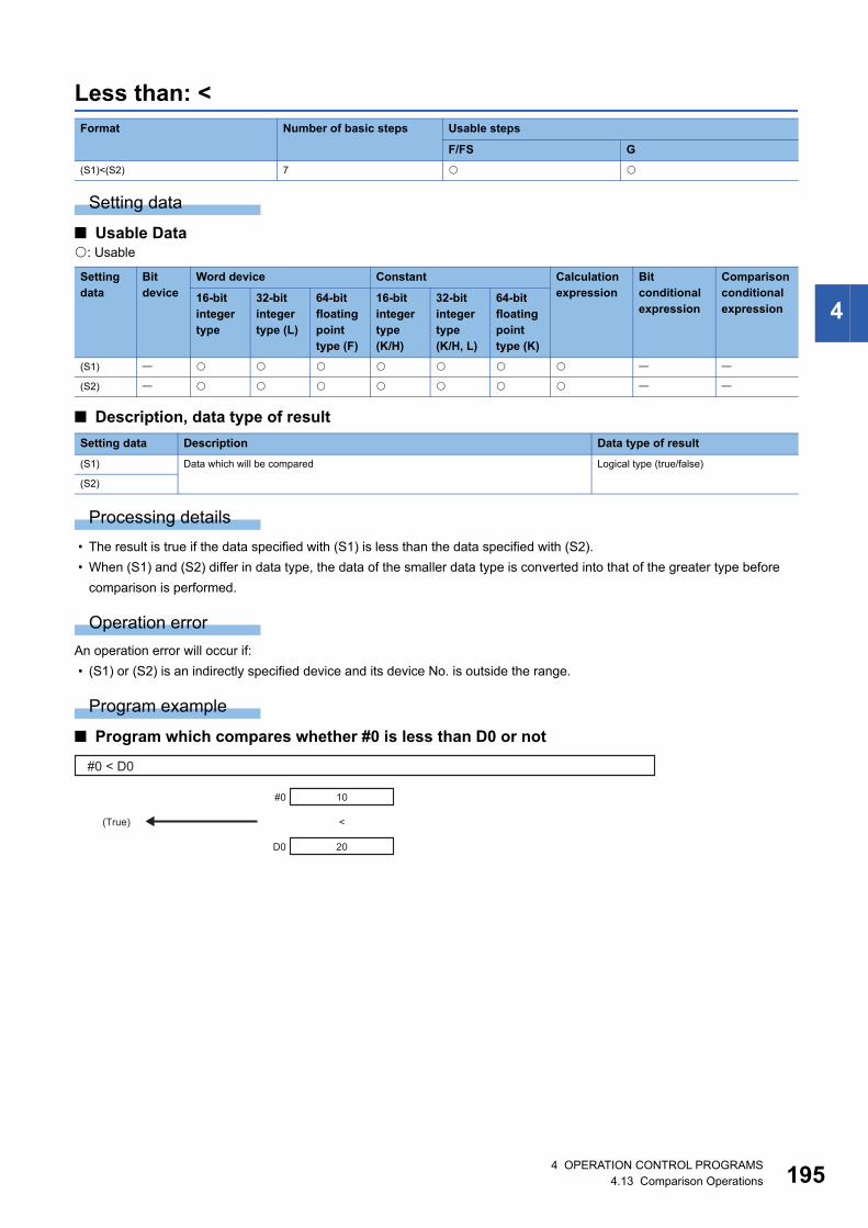
4
Less than: <
Setting data
■ Usable Data: Usable
■ Description, data type of result
Processing details
• The result is true if the data specified with (S1) is less than the data specified with (S2).
• When (S1) and (S2) differ in data type, the data of the smaller data type is converted into that of the greater type before
comparison is performed.
Operation error
An operation error will occur if:
• (S1) or (S2) is an indirectly specified device and its device No. is outside the range.
Program example
■ Program which compares whether #0 is less than D0 or not
Format Number of basic steps Usable steps
F/FS G
(S1)<(S2) 7
Setting data
Bit device
Word device Constant Calculation expression
Bit conditional expression
Comparison conditional expression
16-bit integer type
32-bit integer type (L)
64-bit floating point type (F)
16-bit integer type(K/H)
32-bit integer type(K/H, L)
64-bit floating point type (K)
(S1)
(S2)
Setting data Description Data type of result
(S1) Data which will be compared Logical type (true/false)
(S2)
#0 < D0
(True)
10
20
<
D0
#0
4 OPERATION CONTROL PROGRAMS4.13 Comparison Operations 195

19
Less than or equal to: <=
Setting data
■ Usable Data: Usable
■ Description, data type of result
Processing details
• The result is true if the data specified with (S1) is less than or equal to the data specified with (S2).
• When (S1) and (S2) differ in data type, the data of the smaller data type is converted into that of the greater type before
comparison is performed.
Operation error
An operation error will occur if:
• (S1) or (S2) is an indirectly specified device and its device No. is outside the range.
Program example
■ Program which compares whether #0 is less than or equal to D0 or not
Format Number of basic steps Usable steps
F/FS G
(S1)<=(S2) 7
Setting data
Bit device
Word device Constant Calculation expression
Bit conditional expression
Comparison conditional expression
16-bit integer type
32-bit integer type (L)
64-bit floating point type (F)
16-bit integer type(K/H)
32-bit integer type(K/H, L)
64-bit floating point type (K)
(S1)
(S2)
Setting data Description Data type of result
(S1) Data which will be compared Logical type (true/false)
(S2)
#0 <= D0
(True)
10
20
<=
D0
#0
64 OPERATION CONTROL PROGRAMS4.13 Comparison Operations

4
More than: >
Setting data
■ Usable Data: Usable
■ Description, data type of result
Processing details
• The result is true if the data specified with (S1) is greater than the data specified with (S2).
• When (S1) and (S2) differ in data type, the data of the smaller data type is converted into that of the greater type before
comparison is performed.
Operation error
An operation error will occur if:
• (S1) or (S2) is an indirectly specified device and its device No. is outside the range.
Program example
■ Program which compares whether #0 is greater than D0 or not
Format Number of basic steps Usable steps
F/FS G
(S1)>(S2) 7
Setting data
Bit device
Word device Constant Calculation expression
Bit conditional expression
Comparison conditional expression
16-bit integer type
32-bit integer type (L)
64-bit floating point type (F)
16-bit integer type(K/H)
32-bit integer type(K/H, L)
64-bit floating point type (K)
(S1)
(S2)
Setting data Description Data type of result
(S1) Data which will be compared Logical type (true/false)
(S2)
#0 > D0
(True)
400
20
>
D0
#0
4 OPERATION CONTROL PROGRAMS4.13 Comparison Operations 197

19
More than or equal to: >=
Setting data
■ Usable Data: Usable
■ Description, data type of result
Processing details
• The result is true if the data specified with (S1) is greater than or equal to the data specified with (S2).
• When (S1) and (S2) differ in data type, the data of the smaller data type is converted into that of the greater type before
comparison is performed.
Operation error
An operation error will occur if:
• (S1) or (S2) is an indirectly specified device and its device No. is outside the range.
Program example
■ Program which compares whether #0 is greater than or equal to D0 or not
Format Number of basic steps Usable steps
F/FS G
(S1)>=(S2) 7
Setting data
Bit device
Word device Constant Calculation expression
Bit conditional expression
Comparison conditional expression
16-bit integer type
32-bit integer type (L)
64-bit floating point type (F)
16-bit integer type(K/H)
32-bit integer type(K/H, L)
64-bit floating point type (K)
(S1)
(S2)
Setting data Description Data type of result
(S1) Data which will be compared Logical type (true/false)
(S2)
#0 >= D0
(True)
400
20
>=
D0
#0
84 OPERATION CONTROL PROGRAMS4.13 Comparison Operations
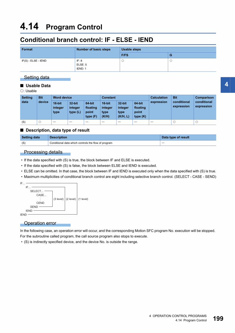
4
4.14 Program Control
Conditional branch control: IF - ELSE - IEND
Setting data
■ Usable Data: Usable
■ Description, data type of result
Processing details
• If the data specified with (S) is true, the block between IF and ELSE is executed.
• If the data specified with (S) is false, the block between ELSE and IEND is executed.
• ELSE can be omitted. In that case, the block between IF and IEND is executed only when the data specified with (S) is true.
• Maximum multiplicities of conditional branch control are eight including selective branch control. (SELECT - CASE - SEND)
Operation error
In the following case, an operation error will occur, and the corresponding Motion SFC program No. execution will be stopped.
For the subroutine called program, the call source program also stops to execute.
• (S) is indirectly specified device, and the device No. is outside the range.
Format Number of basic steps Usable steps
F/FS G
IF(S) - ELSE - IEND IF: 8
ELSE: 5
IEND: 1
Setting data
Bit device
Word device Constant Calculation expression
Bit conditional expression
Comparison conditional expression
16-bit integer type
32-bit integer type (L)
64-bit floating point type (F)
16-bit integer type(K/H)
32-bit integer type(K/H, L)
64-bit floating point type (K)
(S)
Setting data Description Data type of result
(S) Conditional data which controls the flow of program
SELECT...CASE...
SENDIEND
IEND
CEND(3 level) (2 level) (1 level)
IF...IF...
4 OPERATION CONTROL PROGRAMS4.14 Program Control 199

20
Program example
■ Program which adds K10 to #100 when #0 is K100 or adds K20 to #100 when #0 is other than K100
■ Program which executes the speed change of axis 2 with CHGV instruction when M0 or M1 is ON
IF #0 == K100 #100 = #100 + K10ELSE #100 = #100 + K20IEND
IF M0 + M1 CHGV(K2,K10)IEND
04 OPERATION CONTROL PROGRAMS4.14 Program Control

4
Selective branch control: SELECT - CASE - SEND
Setting data
■ Usable Data: Usable
■ Description, data type of result
Processing details
• The block described between CASE and CEND is executed selectively according to the true/false of the data specified with
(S1) to (Sn).
• The true/false evaluation is carried out in order from the top, and the block described between CASE which is first
evaluated to be true and CEND is executed. After that, no true/false evaluation is carried out until SEND, and the next block
of SEND is executed.
• When the data specified with (S1) to (Sn) are all false, the block described from CELSE to CEND is executed.
• CELSE can be omitted. In that case, if the data specified with (S1) to (Sn) are all false, the block between SELECT and
SEND is not executed, and the next block of SEND is executed.
• The following number of CASE(Sn) to CEND can be written between SELECT and SEND
• Maximum multiplicities of selective branch control are eight including conditional branch control. (IF - ELSE - IEND)
Format Number of basic steps Usable steps
F/FS G
SELECT
CASE(S1) - CEND
CASE(S2) - CEND
CASE(Sn) - CEND
CELSE - CEND
SEND
SELECT: 1
CASE: 8
CEND: 5
CELSE: 1
SEND: 1
Setting data
Bit device
Word device Constant Calculation expression
Bit conditional expression
Comparison conditional expression
16-bit integer type
32-bit integer type (L)
64-bit floating point type (F)
16-bit integer type(K/H)
32-bit integer type(K/H, L)
64-bit floating point type (K)
(S) to (Sn)
Setting data Description Data type of result
(S) to (Sn) Conditional data which controls the flow of program
CELSE Number
Not used 64
Used 63
CASE...SELECT...
SELECT...
SENDIEND
CENDSEND
CASE...
CEND
IF...
(3 level) (2 level) (1 level)
4 OPERATION CONTROL PROGRAMS4.14 Program Control 201

20
Operation error
In the following case, an operation error will occur, and the corresponding Motion SFC program No. execution will be stopped.
For the subroutine called program, the call source program also stops to execute.
• (S) is indirectly specified device, and the device No. is outside the range.
Program example
■ Program which adds K10 to #100 when #0 is K100, adds K20 to #100 when #0 is K200 or more, or adds K100 to #100 in other cases
SELECT CASE #0 == K100 #100 = #100 + K10 CEND CASE #0 >= K200 #100 = #100 + K20 CEND CELSE #100 = #100 + K100 CENDSEND
24 OPERATION CONTROL PROGRAMS4.14 Program Control

4
Repeat control with specified count: FOR - NEXT
Setting data
■ Usable Data: Usable
■ Description, data type of result
Processing details
• (S1) is substituted to the device specified with (D) as initial value, and the block between FOR and NEXT is repeatedly
executed.
• The incremental value specified with (S3) is added to the device specified with (D) at every execution of NEXT. If the device
value specified with (D) is larger than the final value specified with (S2), the repeat control of the block between FOR and
NEXT is ended, and the next block of NEXT is executed.
• When the incremental value specified with (S3) is negative number, if the device value specified with (D) is smaller than the
final value specified with (S2), the repeat control of the block between FOR and NEXT is ended.
• STEP can be omitted. If STEP is omitted, the repeat control is executed as "STEP 1".
• Maximum multiplicities of repeat control are eight.
• When data types of (D), (S1), (S2) and (S3) are different, type conversion processing is executed but an unintended
operation may occur. Set the same data type.
Format Number of basic steps Usable steps
F/FS G
FOR(D) = (S1)TO(S2)STEP(S3) - NEXT FOR: 18
NEXT: 15
Setting data
Bit device
Word device Constant Calculation expression
Bit conditional expression
Comparison conditional expression
16-bit integer type
32-bit integer type (L)
64-bit floating point type (F)
16-bit integer type(K/H)
32-bit integer type(K/H, L)
64-bit floating point type (K)
(D)
(S1)
(S2)
(S3)
Setting data Description Data type of result
(D) Device used for loop control counter
(S1) Initial value of loop control counter
(S2) Final value of loop control counter
(S3) Incremental value of loop control counter
FOR...
NEXTNEXT
FOR...
(2 level) (1level)
4 OPERATION CONTROL PROGRAMS4.14 Program Control 203

20
Operation error
In the following case, an operation error will occur, and the corresponding Motion SFC program No. execution will be stopped.
For the subroutine called program, the call source program also stops to execute.
• (S1) data is outside the range of (D) data type.
• (D), (S1), and (S2) are indirectly specified devices, and the device No. is outside the range.
• FOR to NEXT instruction is executed over the limited count for repeat control set in parameter in an operation control
program or a transition program.
Program example
■ Program which repeats to substitute #0 data to Motion register (#) that is indirectly specified with the device No. "#0+100" when #0 is between 1 and 10 (Incremental value is 1.)
When the program is ended, 1 to 10 is substituted to #101 to #110.
When the incremental value is positive number, the device value specified with (D) is larger than the final value specified with
(S2) after FOR to NEXT repeat is completed. In the above example, #0 set in (D) is 11.
■ Program which repeats to subtract #0 from #100 when #0 is between 100 to 10 (Incremental value is -10.).
When the incremental value is negative number, the device value specified with (D) is smaller than the final value specified
with (S2) after FOR to NEXT repeat is completed. In the above example, #0 set in (D) is 0.
Since the incremental value continues to be added to the loop control counter specified with (D) until it
reaches the final value, set the data type which the value can handle. When the data range exceeds the loop
control counter range, an unintended repeat operation may occur as the value is considered to be wrong. In
the following program, the data type of loop control counter #0 is 16-bit integer type, and the data range is
from -32768 to 32767.
When this program is executed, #0 changes as follows and exceeds the 16-bit integer type data range in the
middle. Therefore, the program is not ended with four executions of the loop.
• First execution of the loop: #0 is 0.
• Second execution of the loop: #0 is 10000.
• Third execution of the loop: #0 is 20000.
• Forth execution of the loop: #0 is 30000.
• Fifth execution of the loop: #0 is -25536. (#0 is 40000, but overflow will occur as it is outside the data range.)
• Sixth execution of the loop: #0 is -15536.
FOR #0 = K1 TO K10 #(#0 + K100) = #0NEXT
FOR #0 = K100 TO K10 STEP K-10 #100 = #100 - #0NEXT
FOR #0 = K0 TO K30000 STEP K10000 #1 = #1 + K1NEXT
44 OPERATION CONTROL PROGRAMS4.14 Program Control

4
Forced termination of repeat control: BREAK
Setting data
There are no setting data.
Processing details
• Repeat control with specified count (FOR - NEXT instruction) is forced to terminate, and the program from the next block of
NEXT is executed.
• BREAK is only described within the repeat control processing block between FOR and NEXT.
Operation error
There are no operation errors.
Program example
■ Program which forces to terminate the repeat control processing by FOR to NEXT when M0 or M1 turns ON
Format Number of basic steps Usable steps
F/FS G
BREAK 5
FOR #0 = K1 TO K10 #100 = #100 + K10 IF M0 + M1 BREAK IENDNEXT
4 OPERATION CONTROL PROGRAMS4.14 Program Control 205

20
4.15 Motion-Dedicated Functions
Speed change request: CHGV
Setting data
■ Usable Data: Usable
■ Description, data type of result
Processing details
• A speed change is made shown below.
1. The "[St.1047] Speed change accepting flag (R: M30144+n/Q: M2061+n)" correspond to the axis specified with (S1) is
turned ON.
2. The speed of the axis specified with (S1) is changed to the speed specified with (S2).
3. The speed change accepting flag is turned OFF.
• The axis No. that may be set at (S1) is within the following range.
• For interpolation control, set any one of the interpolation axes to (S1). When linear interpolation control is exercised, a
speed change varies as described below with the positioning speed designation method set in the servo program.
• Operation varies with the sign of the specified speed set at (S2).
Format Number of basic steps Usable steps
F/FS G
CHGV((S1), (S2)) 7
Setting data
Bit device
Word device Constant Calculation expression
Bit conditional expression
Comparison conditional expression
16-bit integer type
32-bit integer type (L)
64-bit floating point type (F)
16-bit integer type(K/H)
32-bit integer type(K/H, L)
64-bit floating point type (K)
(S1)
(S2)
Setting data Description Data type of result
(S1) Axis No. to which speed change request will be given
(S2) Specified speed
Motion CPU Setting range
R64MTCPU 1 to 64
R32MTCPU 1 to 32
R16MTCPU 1 to 16
Positioning speed designation method Operation
Vector speed designation Speed change is made so that the vector speed becomes the speed specified with (S2).
Longest axis designation Speed change is made so that the longest axis speed becomes the speed specified with (S2).
Reference axis speed designation Speed change is made so that the reference axis speed becomes the speed specified with (S2).
Sign of specified speed Operation
Positive Speed change
0 Temporary stop
Negative Return
64 OPERATION CONTROL PROGRAMS4.15 Motion-Dedicated Functions

4
• The specified speed that may be set at (S2) is within the following range.
*1 When the "speed control 10 multiplier setting for degree axis" is set to "valid" in the fixed parameter, the unit is (10-2 [degree/min]).
• The speed changed by CHGV instruction is effective only on the servo program during starting.
• Speed change is not executed for the axis specified with (S1) during deceleration stop.
• Speed change is not executed for the axis specified with (S1) during speed-torque control.
• Speed change is not executed for the axis specified with (S1) during machine control (machine JOG operation, machine
program operation).
• Acceleration/deceleration time at speed change can be changed by setting the acceleration/deceleration time change
parameter of the axis specified with (S1). Refer to the following for acceleration/deceleration time change parameter and
acceleration/deceleration time change function.
MELSEC iQ-R Motion controller Programming Manual (Positioning Control)
• By specifying a negative speed and making a speed change request during the start, allows the axis to start deceleration at
that point and return in the opposite direction upon completion of deceleration. The following operations by the servo
instruction are shown below.
Requested operation Setting range
mm inch degree pulse
Speed change request 0 to 600000000
(10-2 [mm/min])
0 to 600000000
(10-3 [inch/min])
0 to 2147483647
(10-3 [degree/min])*10 to 2147483647
[pulse/s]
Return request -1 to -600000000
(10-2 [mm/min])
-1 to -600000000
(10-3 [inch/min])
-1 to -2147483647
(10-3 [degree/min])*1-1 to -2147483647
[pulse/s]
Control mode Servo instruction Operation
Linear control On completion of deceleration, the axis reverses its moving direction, returns to
the positioning starting point at the absolute value of the specified speed, and
stops (waits) there. For circular interpolation, the axis returns in the circular path.
Circular interpolation
control
Fixed-pitch feed
Continuous trajectory
control
On completion of deceleration, the axis reverses its moving direction, returns to
the preceding point at the absolute value of the specified speed, and stops
(waits) there.
Speed control () On completion of deceleration, the axis reverses its moving direction at the
absolute value of the specified speed.
The axis does not stop until a stop instruction is input.Speed control ()
Speed/position switching
control
The axis cannot return.
The speed change request is regarded as a normal speed change request.
Warning (error code: 0991H) will occur and the axis will be controlled at the
speed limit value.Position follow-up control
Speed control with fixed
position stop
JOG operation
High-speed oscillation A speed change cannot be made. Warning (error code: 09EEH) will occur.
Home position return A speed change cannot be made. Warning (error code: 09EDH) will occur.
ABS-1 ABS-2 ABS-3 ABS-4
INC-1 INC-2 INC-3 INC-4
ABS circular INC circular
FEED-1 FEED-2 FEED-3
CPSTART1 CPSTART2
CPSTART3 CPSTART4
VF VR
VVF VVR
VPF VPR VPSTART
PFSTART
PVF PVR
OSC
ZERO
4 OPERATION CONTROL PROGRAMS4.15 Motion-Dedicated Functions 207

20
■ Controls • If a speed change is made to a negative speed, control is executed with the control mode during the start as indicated in the
above table.
• The returning command speed is the absolute value of a new speed.
• When the axis is waiting at the return position.
• While the axis is reversion in the speed control mode
• A speed change to a negative speed will not be made for the axis which set the stroke limit as invalid.
Operation error
An operation error will occur and a speed change will not be made if:
• The specified axis No. of (S1) is outside the range.
• (S2) is an indirectly specified device and its device No. is outside the range.
A warning will occur and a speed change will not be made if:
• The axis specified with (S1) was performing home position return (warning (error code: 09EDH)).
• A speed change to a negative speed was made for the axis which set the stroke limit as invalid (warning (error code:
09EFH)).
If the speed change is executed for the axis specified with (S1) during deceleration, the speed change is
ignored. An error will not occur in this case.
A warning will occur and the axis to be controlled at the speed limit value if:
• The absolute value of the speed specified with (S2) is greater than the speed limit value (warning (error code: 0991H)).
If the absolute value of a negative new speed is higher than the speed specified with the servo program during
continuous trajectory control, return control is exercised at the speed specified in the program (speed clamp
control for a speed change during continuous trajectory control). At this time, an error will not occur.
Program example
■ Program which changes the positioning speed of axis 2
• Signal states
Signal name Status
[St.1040] Start accept flag (R: M30080+n/Q: M2001+n) ON (unchanged from before execution of CHGV instruction)
[St.1060] Positioning start complete (R: M32400+32n/Q: M2400+20n) ON (unchanged from before execution of CHGV instruction)
[St.1061] Positioning complete (R: M32401+32n/Q: M2401+20n) OFF
[St.1062] In-position (R: M32402+32n/Q: M2402+20n) ON
[St.1063] Command in-position (R: M32403+32n/Q: M2403+20n) OFF
[St.1049] Speed change "0" accepting flag (R: M30272+n/Q: M2240+n) ON
• Make a speed change to a positive speed for a restart.
• Turn on the stop command to end the positioning.
• A negative speed change made again will be ignored.
• Make a speed change to a positive speed to change the travel direction again.
• Turn ON the stop command to make a stop.
• A speed change is made in the opposite direction if a negative speed change is made again.
CHGV(K2,K10)
84 OPERATION CONTROL PROGRAMS4.15 Motion-Dedicated Functions

4
■ Return program which changes the positioning speed of axis 1 to a negative value
The following operation will be performed when a return request is made in continuous trajectory control.
If a speed change to a negative speed is made during execution of positioning to P2 as shown above, the axis returns to P1
along the program specified locus and waits at P1.
[Precautions at speed change]
• A speed change may be invalid if the speed change is executed until the "positioning start complete signal"
status changes to ON at servo program start request . When making a speed change at almost the same
timing as a start, create a program to execute speed change after the "positioning start complete signal" has
turned on.
• When the reverse return is requested during stop in the state of FIN waiting using the M-code FIN signal
wait function in continuous trajectory control, it will be ignored.
• In the example of previous page, if reverse return is requested before P2 and the axis passes through P2
during deceleration, it return to P2.
• There will be a delay of time equivalent to an operation cycle at the maximum in the response time from
when the CHGV instruction is executed until the speed begins to change actually.
CHGV(K1,K-1000)
CPSTART2 Axis 1 Axis 2 Speed 1000ABS-2 Axis 1, 10000 Axis 2, 0ABS-2 Axis 1, 10000 Axis 2, 10000ABS-2 Axis 1, 20000 Axis 2, 10000CPEND
Start request
[Locus]
Vector speed
[St.1040] Start accept flag(R: M30080+n/Q: M2001+n)
Speed change requestCHGV
Command in-position (OFF)Return operation to point
Speed change "0" acceptingflag
New Speed -1000 1000
Waiting at P1
Starting point Axis 1
Axis 2
Negative speed change
P1
P2 P3
[Servo program]
P1
P2
P3
Reverse return is requested here.
Starting point Axis 1
Axis 2
P1
P2 P3
4 OPERATION CONTROL PROGRAMS4.15 Motion-Dedicated Functions 209

21
Command generation axis speed change request: CHGVS
Setting data
■ Usable Data: Usable
■ Description, data type of result
Processing details
• A speed change is made shown below.
1. The "[St.346] Command generation axis speed change accepting flag (R: M36751+32n/Q: M9811+20n)" corresponding
to the axis specified with (S1) is turned ON.
2. The speed of the axis specified with (S1) is changed to the speed specified with (S2).
3. The speed change accepting flag is turned OFF.
• The axis No. that may be set at (S1) is within the following range.
• For interpolation control, set any one of the interpolation axes to (S1). When linear interpolation control is exercised, a
speed change varies as described below with the positioning speed designation method set in the servo program.
• Operation varies with the sign of the specified speed set at (S2).
Format Number of basic steps Usable steps
F/FS G
CHGVS((S1), (S2)) 7
Setting data
Bit device
Word device Constant Calculation expression
Bit conditional expression
Comparison conditional expression
16-bit integer type
32-bit integer type (L)
64-bit floating point type (F)
16-bit integer type(K/H)
32-bit integer type(K/H, L)
64-bit floating point type (K)
(S1)
(S2)
Setting data Description Data type of result
(S1) Axis No. to which speed change request will be given
(S2) Specified speed
Motion CPU Setting range
R64MTCPU 1 to 64
R32MTCPU 1 to 32
R16MTCPU 1 to 16
Positioning speed designation method Operation
Vector speed designation Speed change is made so that the vector speed becomes the speed specified with (S2).
Longest axis designation Speed change is made so that the longest axis speed becomes the speed specified with (S2).
Reference axis speed designation Speed change is made so that the reference axis speed becomes the speed specified with (S2).
Sign of specified speed Operation
Positive Speed change
0 Temporary stop
Negative Return
04 OPERATION CONTROL PROGRAMS4.15 Motion-Dedicated Functions

4
• The specified speed that may be set at (S2) is within the following range.
*1 When the "speed control 10 multiplier setting for degree axis" is set to "valid" in the fixed parameter, the unit is (10-2 [degree/min]).
• The speed changed by CHGVS instruction is effective only on the servo program during starting.
• The speed change does not executed for the axis specified with (S1) during deceleration stop.
• Acceleration/deceleration time at speed change can be changed by setting the acceleration/deceleration time change
parameter of the axis specified by (S1). Refer to the following for acceleration/deceleration time change parameter.
MELSEC iQ-R Motion controller Programming Manual (Advanced Synchronous Control)Refer to the following for
acceleration/deceleration time change function.
MELSEC iQ-R Motion controller Programming Manual (Positioning Control)
• By specifying a negative speed and making a speed change request during the start, allows the axis to start deceleration at
that point and return in the opposite direction upon completion of deceleration. The following operations by the servo
instruction are shown below.
Requested operation Setting range
mm inch degree pulse
Speed change request 0 to 600000000
(10-2 [mm/min])
0 to 600000000
(10-3 [inch/min])
0 to 2147483647
(10-3 [degree/min])*10 to 2147483647
[pulse/s]
Return request -1 to -600000000
(10-2 [mm/min])
-1 to -600000000
(10-3 [inch/min])
-1 to -2147483647
(10-3 [degree/min])*1-1 to -2147483647
[pulse/s]
Control mode Servo instruction Operation
Linear control On completion of deceleration, the axis reverses its moving direction, returns to
the positioning starting point at the absolute value of the specified speed, and
stops (waits) there. For circular interpolation, the axis returns in the circular path.
Circular interpolation
control
Fixed-pitch feed
Continuous trajectory
control
On completion of deceleration, the axis reverses its moving direction, returns to
the preceding point at the absolute value of the specified speed, and stops
(waits) there.
Speed control () On completion of deceleration, the axis reverses its moving direction at the
absolute value of the specified speed.
The axis does not stop until a stop instruction is input.
Position follow-up control The axis cannot return.
The speed change request is regarded as a normal speed change request.
Warning (error code: 0991H) will occur and the axis will be controlled at the
speed limit value.Speed control with fixed
position stop
JOG operation
ABS-1 ABS-2 ABS-3 ABS-4
INC-1 INC-2 INC-3 INC-4
ABS circular INC circular
FEED-1 FEED-2 FEED-3
CPSTART1 CPSTART2
CPSTART3 CPSTART4
VF VR
PFSTART
PVF PVR
4 OPERATION CONTROL PROGRAMS4.15 Motion-Dedicated Functions 211

21
■ Controls • If a speed change is made to a negative speed, control is executed with the control mode during the start as indicated in the
above table.
• The returning command speed is the absolute value of a new speed.
• When the axis is waiting at the return position.
• While the axis is reversion in the speed control mode
• A speed change to a negative speed will not be made for the axis which set the stroke limit as invalid.
Operation error
An operation error will occur and a speed change will not be made if:
• The specified axis No. of (S1) is outside the range.
• (S2) is an indirectly specified device and its device No. is outside the range.
A warning will occur and a speed change will not be made if:
• A speed change to a negative speed was made for the axis which set the stroke limit as invalid (warning (error code:
09EFH)).
If the speed change is executed for the axis specified with (S1) during deceleration, the speed change is
ignored. An error will not occur in this case.
A warning will occur and the axis to be controlled at the speed limit value if:
• The absolute value of the speed specified with (S2) is greater than the speed limit value (warning (error code: 0991H)).
If the absolute value of a negative new speed is higher than the speed specified with the servo program during
continuous trajectory control, return control is exercised at the speed specified in the program (speed clamp
control for a speed change during continuous trajectory control). At this time, an error will not occur.
• Signal states
Signal name Status
[St.345] Command generation axis start accept flag
(R: M36750+32n/Q: M9810+20n)
ON (unchanged from before execution of CHGVS instruction)
[St.340] Command generation axis positioning start complete
(R: M36560+32n/Q: M9800+20n)
ON (unchanged from before execution of CHGVS instruction)
[St.341] Command generation axis positioning complete
(R: M36561+32n/Q: M9801+20n)
OFF
[St.342] Command generation axis command in-position
(R: M36563+32n/Q: M9803+20n)
OFF
[St.347] Command generation axis speed change "0" accepting flag
(R: M36572+32n/Q: M9812+20n)
ON
• Make a speed change to a positive speed for a restart.
• Turn on the stop command to end the positioning.
• A negative speed change made again will be ignored.
• Make a speed change to a positive speed to change the travel direction again.
• Turn ON the stop command to make a stop.
• A speed change is made in the opposite direction if a negative speed change is made again.
24 OPERATION CONTROL PROGRAMS4.15 Motion-Dedicated Functions

4
Program example
■ Program which changes the positioning speed of axis 2
[Precautions at speed change]
• A speed change may be invalid if the speed change is executed until the "positioning start complete signal"
status changes to ON at servo program start request. When making a speed change at almost the same
timing as a start, create a program to execute speed change after the "positioning start complete signal" has
turned on.
• When the reverse return is requested during stop in the state of FIN waiting using the M-code FIN signal
wait function in continuous trajectory control, it will be ignored.
• In the example of previous page, if reverse return is requested before P2 and the axis passes through P2
during deceleration, it return to P2.
• There will be a delay of time equivalent to an operation cycle at the maximum in the response time from
when the CHGVS instruction is executed until the speed begins to change actually.
CHGVS(K2,K10)
Reverse return is requested here.
Starting point Axis 1
Axis 2
P1
P2 P3
4 OPERATION CONTROL PROGRAMS4.15 Motion-Dedicated Functions 213
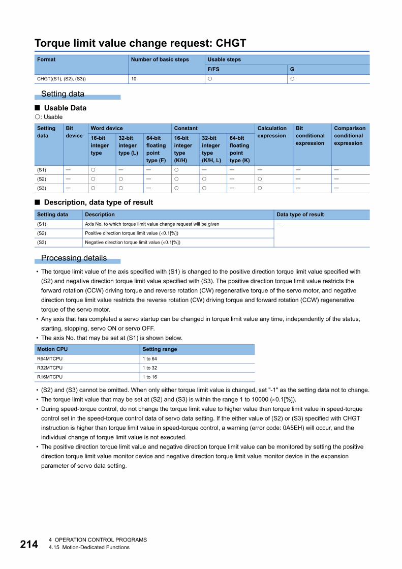
21
Torque limit value change request: CHGT
Setting data
■ Usable Data: Usable
■ Description, data type of result
Processing details
• The torque limit value of the axis specified with (S1) is changed to the positive direction torque limit value specified with
(S2) and negative direction torque limit value specified with (S3). The positive direction torque limit value restricts the
forward rotation (CCW) driving torque and reverse rotation (CW) regenerative torque of the servo motor, and negative
direction torque limit value restricts the reverse rotation (CW) driving torque and forward rotation (CCW) regenerative
torque of the servo motor.
• Any axis that has completed a servo startup can be changed in torque limit value any time, independently of the status,
starting, stopping, servo ON or servo OFF.
• The axis No. that may be set at (S1) is shown below.
• (S2) and (S3) cannot be omitted. When only either torque limit value is changed, set "-1" as the setting data not to change.
• The torque limit value that may be set at (S2) and (S3) is within the range 1 to 10000 (0.1[%]).
• During speed-torque control, do not change the torque limit value to higher value than torque limit value in speed-torque
control set in the speed-torque control data of servo data setting. If the either value of (S2) or (S3) specified with CHGT
instruction is higher than torque limit value in speed-torque control, a warning (error code: 0A5EH) will occur, and the
individual change of torque limit value is not executed.
• The positive direction torque limit value and negative direction torque limit value can be monitored by setting the positive
direction torque limit value monitor device and negative direction torque limit value monitor device in the expansion
parameter of servo data setting.
Format Number of basic steps Usable steps
F/FS G
CHGT((S1), (S2), (S3)) 10
Setting data
Bit device
Word device Constant Calculation expression
Bit conditional expression
Comparison conditional expression
16-bit integer type
32-bit integer type (L)
64-bit floating point type (F)
16-bit integer type(K/H)
32-bit integer type(K/H, L)
64-bit floating point type (K)
(S1)
(S2)
(S3)
Setting data Description Data type of result
(S1) Axis No. to which torque limit value change request will be given
(S2) Positive direction torque limit value (0.1[%])
(S3) Negative direction torque limit value (0.1[%])
Motion CPU Setting range
R64MTCPU 1 to 64
R32MTCPU 1 to 32
R16MTCPU 1 to 16
44 OPERATION CONTROL PROGRAMS4.15 Motion-Dedicated Functions

4
Operation error
An operation error will occur and a torque limit value change will not be made if:
• The specified axis No. at (S1) is outside the range.
• (S2) or (S3) is an indirectly specified device and its device No. is outside the range.
A warning will occur and a torque limit value change will not be made if:
• The torque limit value specified with (S2) or (S3) is outside the range of 0.1 to 1000.0[%] (warning (error code: 0A5BH)).
• The CHGT instruction is executed for any axis that has not yet been started (warning (error code: 0A5CH)).
• When the CHGT instruction is executed for any axis during speed-torque control, the value of (S2) or (S3) is greater than
the torque limit value in speed-torque control (warning (error code: 0A5EH)).
Program example
■ Program which changes the torque limit value of axis 2 to positive direction 20.0[%] and to negative direction 10.0[%]
There will be a delay of time equivalent to an operation cycle at the maximum in the time from when the CHGT
instruction is executed until the torque limit value is transferred to servo amplifier actually.
CHGT(K2,K200,K100)
4 OPERATION CONTROL PROGRAMS4.15 Motion-Dedicated Functions 215

21
Target position change request: CHGP
Setting data
■ Usable Data: Usable
■ Description, data type of result
The CHGP instruction cannot be used for the command generation axis under advanced synchronous control.
Format Number of basic steps Usable steps
F/FS G
CHGP((S1), (S2), (S3)) 11
Setting data
Bit device
Word device Constant Calculation expression
Bit conditional expression
Comparison conditional expression
16-bit integer type
32-bit integer type (L)
64-bit floating point type (F)
16-bit integer type(K/H)
32-bit integer type(K/H, L)
64-bit floating point type (K)
(S1)
(S2)
(S3)
Setting data Description Data type of result
(S1) Axis No. to which target position change request will be given
(S2) Specified method of changed address
0: Address method
1: Movement method
(S3) Starting No. of device to store target position change value
64 OPERATION CONTROL PROGRAMS4.15 Motion-Dedicated Functions

4
Processing details
• The target position is changed during positioning instruction execution by target position change request. New target
position can be set by the absolute address or relative movement amount from feed current value at target position change
request. Operation for executing target position change request to (X, Y) = (400.0m, 500.0m) by absolute address
setting during linear interpolation control from positioning start position (X, Y) = (0.0m, 0.0m) to (X, Y) = (800.0m,
600.0m) is shown below.
• The target position of the axis specified with (S1) is changed. The new target position is calculated by a value stored in the
device specified with (S3) using the method specified with (S2).
• CHGP instruction is enabled to only starting axis.
• The target position is not changed when the specified axis is during deceleration stop.
• There will be a delay of time equivalent to an operation cycle at the maximum from when the CHGP
instruction is executed until the target position is changed actually.
• When the CHGP instruction is executed at servo program start request ("[St.1060] Positioning start
complete (R: M32400+32n/Q: M2400+20n)" is OFF), the target position change becomes disabled. Create
the program to execute the target position change after positioning start complete signal ON to change the
target position at same timing with servo program start.
Axis 2 speed
OFFON
Axis 1 speed
[St.1040] Start accept flag (R: M30080+n/Q: M2001+n)
OFFON
Target position change request(CHGP) (Internal process image)
OFFON
[St.1063] Command in-position(R: M32403+32n/Q: M2403+20n)
OFFON
[St.1061] Positioning start complete(R: M32401+32n/Q: M2401+20n)
Vector speed
Ychg Position at target position change(X,Y) = (Xchg, Ychg)
Target position after change(X,Y) = (400.0�m, 500.0�m)
Target position before change (X,Y) = (800.0�m, 600.0�m)
Axis 1 movement amount after target position change(400.0�m - Xchg)
Axis 2 movement amount after target position change(500.0�m - Ychg)
500.0�m
600.0�m
Axis 2(Y)
Axis 1(X)0.0�m 400.0�m 800.0�mXchg
4 OPERATION CONTROL PROGRAMS4.15 Motion-Dedicated Functions 217

21
• The axis No. that may be set at (S1) is within the following range. For interpolation control, set any one of the interpolation
axes to (S1).
• The target position by setting of (S2) is shown below.
When "1" (movement method) is set to (S2) and the CHGP instruction is executed with a normal task, a
dispersion may occur for new target position depending on a dispersion of instruction accept timing. Execute
the CHGP instruction in the fixed cycle task same as operation cycle to inhibit a dispersion.
• Set the starting device No. to store a target position change value at (S3). Set an even number as first device, and set a
target position change value as follows.
Ex.
When the target position change request is executed during INC-3 instruction execution.
The axis No. for target position change value 1 to 4 are as follows.
• Target position change value 1: Setting of axis No.1
• Target position change value 2: Setting of axis No.3
• Target position change value 3: Setting of axis No.4
• Target position change value 4: Not necessary to set
Motion CPU Setting range
R64MTCPU 1 to 64
R32MTCPU 1 to 32
R16MTCPU 1 to 16
• When "0" (address method) is set to (S2), the target position is the target position change value stored in the device specified with (S3).
• When "1" (movement method) is set to (S2), the target position is the position that the movement for target position change value stored in the device
specified with (S3) is executed from the feed current value at CHGP instruction execution.
Offset Name Setting range
mm inch pulse degree
Address method Movement method
+0 Target position
change value 1
-2147483648 to
2147483647
(10-1 [m])
-2147483648 to
2147483647
(10-5 [inch])
-2147483648 to
2147483647
([pulse])
0 to 35999999
(10-5 [degree])
-2147483648 to
2147483647
(10-5 [degree])+1
+2 Target position
change value 2+3
+4 Target position
change value 3+5
+6 Target position
change value 4+7
• Set the positioning address and movement amount according to the setting of (S2) for target position change value.
• Set the axis No. among interpolation axes in ascending order for target position change value.
[K100] INC-3 Axis Axis Axis Speed
3,4,1,
3000pulse 4000pulse 4000pulse10000pulse/s
84 OPERATION CONTROL PROGRAMS4.15 Motion-Dedicated Functions

4
• The following operations by the servo instruction at CHGP instruction execution are shown below.
• Operation after execution of CHGP instruction are as follows.
• After execution of CHGP instruction, the vector speed does not change, but each axis speed changes according to new
target position. Therefore, each axis speed may change rapidly depending on new target position.
• When the reference axis speed designation or longest axis reference designation is set in the linear interpolation control, an
operation is as follows.
Control mode Servo instruction Operation
Linear control The positioning is executed from current feed value during execution to new
target position with linear interpolation control.
Fixed-pitch feed
Circular interpolation
control
The target position change is ignored, and a warning (error code: 099BH ) will
occur.
Helical interpolation
control
Continuous trajectory
control
The positioning is executed from current feed value during execution to new
target position with linear interpolation control. The positioning to a remaining
point is not executed.
Speed control () The target position change is ignored, and a warning (error code: 099BH) will
occur.
Speed control ()
Speed/position switching
control
Position follow-up control
Speed control with fixed
position stop
JOG operation
Speed-torque control
Pressure control
High-speed oscillation
Home position return
Machine control The target position change is ignored.
• "[St.1048] Automatic decelerating flag (R: M30208+n/Q: M2128+n)" turns ON with automatic deceleration processing to new target position.
• "[St.1063] Command in-position (R: M32403+32n/Q: M2403+20n)" turns ON when the absolute value of difference between new target position and
current feed value becomes "command in-position range" or less.
• "[St.1061] Positioning complete (R: M32401+32n/Q: M2401+20n)" turns ON with command output completion to new target position.
• The longest axis is not selected again at target position change. The longest axis before change is used continuously.
• The positioning speed is calculated depending on the movement amount for each axis new target position.
• When the movement amount of reference axis or longest axis depending on the target position change becomes 0, a minor error (error code: 1A5FH) will
occur and deceleration stop is executed.
ABS-1 ABS-2 ABS-3 ABS-4
INC-1 INC-2 INC-3 INC-4
FEED-1 FEED-2 FEED-3
ABS circular INC circular
ABS helical INC helical
CPSTART1 CPSTART2
CPSTART3 CPSTART4
VF VR
VVF VVR
VPF VPR VPSTART
PFSTART
PVF PVR
OSC
ZERO
4 OPERATION CONTROL PROGRAMS4.15 Motion-Dedicated Functions 219

22
• The positioning is executed to new target position with CHGP instruction during continuous trajectory control. The
positioning to a point since executing point at target position change request is not executed.
• The positioning is executed with the setting items of executing point for CHGP instruction.
• The linear interpolation control is executed in all axes specified with CPSTART for CHGP instruction. Set
target position for all axes specified with CPSTART.
• When the CHGP instruction is executed during positioning to a point of circular interpolation or helical
interpolation in the continuous trajectory control, the target position change is executed at the same time of
positioning to a point of linear interpolation.
• When the target position change of address method to the axis of control unit [degree] is executed, operation is as follows.• The positioning to new address is executed in the current direction.
• Set "0 to 35999999 10-5 [degree] as new address at the address method. If the outside of range is set, a minor error (error code: 1A5CH) will occur and
deceleration stop is executed.
Start request OFFON
ON
[Servo program]
<K200>
[Locus]
OFFON
OFF
[St.1040] Start accept flag(R: M30080+n/Q: M2001+n)
Target position change requestCHGP
[St.1061] Positioning complete(R: M32401+32n/Q: M2401+20n)
Vector speedt
OFFON
[Md.25] M-code(R: D32013+48n/Q: D13+20n) 100 200
0Axis 1
Axis 2
Target position after change
P1
P2 P3
CPSTART2 Axis 1 Axis 2 Speed 2000ABS-2 Axis 1, 10000 Axis 2, 0 Speed 1000 M-code 100ABS-2 Axis 1, 12000 Axis 2, 10000 Speed 2000 M-code 200ABS-2 Axis 1, 20000 Axis 2, 10000 M-code 300CPEND
P1
P2
P3
04 OPERATION CONTROL PROGRAMS4.15 Motion-Dedicated Functions

4
• Operation for the movement amount to new target position is less than deceleration distance required to deceleration stop
from speed during control by execution of CHGP instruction is as follows.
• When the negative speed change is executed after execution of CHGP instruction, a deceleration is executed to speed 0.
Then, it returns to position at target position change (CHGP instruction accept), and stops (waits) there.
Operation error
An operation error will occur and a target position change will not be made if:
• The specified axis No. at (S1) is outside the range.
• Except 0 to 1 is set at (S2).
• (S3) is not an even-numbered device.
• The device No. (S3) to (S3) +7 is outside the range.
A warning or minor error will occur and a target position change will not be made if:
• During home position return for target axis (warning (error code: 099BH)).
• During execution of servo program that does not correspond with the target position change for target axis (warning (error
code: 099BH)).
• New target position exceeded the stroke limit range (minor error (error code: 1A5EH)).
• FIN acceleration/deceleration or advanced S-curve acceleration/deceleration as acceleration/deceleration method is set
(minor error (error code: 19E6H)).
• When the reference axis speed designation or longest axis designation is set in the linear interpolation control, the
movement amount for reference axis or longest axis after target position change becomes 0 (minor error (error code:
1A5FH)).
• When the target position change of address method to the axis of control unit [degree] is executed, new address is outside
the range of 0 to 35999999 10-5 [degree] (minor error (error code: 1A5CH)).
• The movement amount to new target position is less than deceleration distance required to deceleration stop from speed
during control (minor error (error code: 1A5DH)).
• A minor error (error code: 1A5DH) will occur and deceleration stop is executed at execution of CHGP instruction.
• The difference between movement amount to the deceleration stop and movement amount to new target position is overrun.
• The "[St.1061] Positioning complete (R: M32401+32n/Q: M2401+20n)" does not turn ON.
OFF
t
V
ON
OFFON
OFF[St.1061] Positioning complete(R: M32401+32n/Q: M2401+20n)
[St.1067] Error detection(R: M32407+32n/Q: M2407+20n)
Target position changerequest CHGP
Movement amount to targetposition after changeOverrun
OFF
Axis 1
Axis 2[Locus]Position at targetposition change
ON
OFF
ON
Speed change request CHGV (Negative speed change)
Target position change requestCHGP
Vector speed
Target position before change
New target position
Speed at negative speed change
Positioning start
Absolute value of negative speed specified with CHGV
4 OPERATION CONTROL PROGRAMS4.15 Motion-Dedicated Functions 221

22
Program example
■ Program which executes the target position change by movement method to axis 2 and axis 8 during positioning by ABS-2
Axis 2 speed
[St.1040] Start accept flag (R: M30080+n/Q: M2001+n)
Target position changerequest CHGP
Start request
X1
Vector speed
0
0
t
10000
3000
Axis 8[Locus]
Axis 220000
5000
-3000
0t
Axis 8 speed
0t
[Motion SFC program][Servo program]
[F10]
[G10]
[F20]
D3000L=K5000 //Axis 2D3002L=K-3000//Axis 8
//Target position change by movement method to axis 2 and 8CHGP(K2,K1,D3000)
X001//Standby until X1 turns ON
<K50>
ABS-2Axis 2, 20000Axis 8, 10000Speed 3000
24 OPERATION CONTROL PROGRAMS4.15 Motion-Dedicated Functions

4
Machine program operation start request: MCNST
Setting data
■ Usable Data: Usable
■ Description, data type of result
*1 For operating system software version "09" or earlier, 78 to 5444.
Processing details
• Machine program operation start request is performed for the machine positioning data from the starting No. specified with
(S1), for an area size specified with (S2).
• Refer to the following for machine positioning data stored in the device specified with (S1).
MELSEC iQ-R Motion Controller Programming Manual (Machine Control)
• The machine positioning data that may be set at (S2) is within the range 78 to 10820 (for operating system software version
"09" or earlier, 78 to 5444).
Operation error
An operation error will occur and a machine program operation start request will not be made if:
• (S1) is not an even-numbered device. (Details code: 1)
• The device No. of (S1)+(S2) is outside the range. (Details code: 2)
• Instruction area for MCNST instruction is not enough. (9 or more instructions operate in the Motion dedicated PLC
instruction (M(P).MCNST/D(P).MCNST) and Motion dedicated function (MCNST))(Details code: 3)
• Machine positioning data area settings are wrong. (Details code: 4)
• The points set to the data area in (S2) are not inside the range of 78 to 10820 (for operating system software version "09"
or earlier, 78 to 5444). (Details code: 4)
• There is an excess/deficiency in the data area points for the area calculated from the number of points for every point.
(Details code: 4)
• The number of positioning points is outside the range of 1 to 256 (for operating system software version "09" or earlier, 1 to
128). (Details code: 4)
• The control method specified by machine positioning data is wrong. (includes when the control method for every point is
NOP only) (Details code: 5)
• The machine No. specified by machine positioning data is outside of range. (Details code: 6)
Format Number of basic steps Usable steps
F/FS G
MCNST((S1), (S2)) 7
Setting data
Bit device
Word device Constant Calculation expression
Bit conditional expression
Comparison conditional expression
16-bit integer type
32-bit integer type (L)
64-bit floating point type (F)
16-bit integer type(K/H)
32-bit integer type(K/H, L)
64-bit floating point type (K)
(S1)
(S2)
Setting data Description Data type of result
(S1) Starting No. of device where machine positioning data is stored.
(S2) Size (words) of machine positioning data area (78 to 10820)*1
4 OPERATION CONTROL PROGRAMS4.15 Motion-Dedicated Functions 223

22
Program example
■ Program for machine program operation start request which performs linear interpolation to positioning point P100 at a command speed of 10000 for the machine 1 that consists of axis 1 and axis 2.
[F10] //Set machine positioning data 1//Number of points, Machine No.D2000=K1 // Number of positioning points(1)D2001=K1 // Machine No.
[F11] //Set machine positioning data 2//Data items for positioning(common)D2002L=H0L // Data items setting for positioning(all disabled)FMOV D2004,K0,K32 // Expansion point items setting value (For 32 words)(Not used(0))
[F12] //Set data for positioning point (1)#0=H0100 // Control method(linear interpolation (ABS))#1=K0 // Specify positioning point(world coordinate system)#2L=K10000L // Command speed=100.00[mm/min]#4=K100 // Point block No.(P100)#5=K0 // Auxiliary/central point block data(Not used(0))#6L=K0L // Radius(Not used(0))#8=K0 // Expansion point item setting(all disabled)#9=K0 // Empty (0)FMOV #10,K0,K32 // Expansion point items setting value (For 32 words)(Not used(0))BMOV D2036,#0,K42 // Batch transmit 42 words from #0 to positioning point (1)
MCNST(D2000,K78) // Machine program operation start request[F13]
[G10]!M43911 // Wait for machine No.1 start accept flag OFF
MCNST(D2000,K78)
44 OPERATION CONTROL PROGRAMS4.15 Motion-Dedicated Functions

4
4.16 Advanced Synchronous Control Dedicated Function
Cam data read: CAMRD
Setting data
■ Usable data: Usable
■ Description, data type of result
Processing details
• Of the cam No. data specified with (S1), the (S3) cam data of the (n) number of points, starting from the position specified
with (S2), is read. The read cam data is stored in the device specified with (D) or later. However, (S2) and (n) are ignored
when an auto-generation format cam is read.
• Set the cam data first position specified with (S2) within the following range.
*1 Since the stroke ratio of the zeroth point cam data is fixed at 0%, the cam data cannot be read.
Format Number of basic steps Usable steps
F/FS G
CAMRD (S1), (S2), (n), (D), (S3) 16
Setting data
Bit device
Word device Constant Calculation expression
Bit conditional expression
Comparison conditional expression
16-bit integer type
32-bit integer type (L)
64-bit floating point type (F)
16-bit integer type(K/H)
32-bit integer type(K/H, L)
64-bit floating point type (K)
(S1)
(S2)
(n)
(D)
(S3)
Setting data Description Data type of result
(S1) Cam No. (1 to 1024)
(S2) Cam data first position
Stroke ratio data format: 1 to cam resolution
Coordinate data format: 0 to (Coordinate number-1)
Auto-generation data format: 0
(n) Number of cam data points
Stroke ratio data format: 1 to 32768
Coordinate data format: 1 to 16384
Auto-generation data format: 0
(D) Start device No. which stores the reading cam data
(S3) Call source
0: Built-in memory of the cam open area (default value)
2: Cam file on the SD memory card
4: Cam file on the standard ROM
Data format First position range
Stroke ratio data format 1 to cam resolution*1
Coordinate data format 0 to (Coordinate number-1)
4 OPERATION CONTROL PROGRAMS4.16 Advanced Synchronous Control Dedicated Function 225

22
• Specify the number of read points for (n). Specify the number of read points so that the device No. storing the end point
data is within the range. The following shows the operation when the number of read points, starting from the first position,
is outside the cam data range.
• The device No. specified with (D) should be an even number. The read cam data is stored in the specified device according
to the cam data format as follows.
■ Stroke ratio data format
■ Coordinate data format
For coordinate data format, when reading is not completed in one attempt, divide the reading over several
attempts.
Data format Operation
Stroke ratio data format If the value calculated from "(S2) + (n) - 1" is larger than the cam resolution, the cam data, ranging from the cam data first
position to the cam resolution, is read.
Coordinate data format If the value calculated from "(S2) + (n)" is larger than the number of coordinates, the cam data, ranging from the cam data first
position to the last coordinate, is read.
Offset Item Range
+0 Can data format (Stroke ratio data format) 1
+1 Cam data starting point 0 to (Coordinate resolution-1)
+2 Cam resolution 256/512/1024/2048/4096/8192/16384/32768
+3
+4 Stroke ratio at first point cam data value -2147483648 to 2147483647[10-7%]
(-214.7483648 to 214.7483647[%])+5
+6 Stroke ratio at second point cam data value
+7
+(2N+2) Stroke ratio at Nth point cam data value
+(2N+3)
Offset Item Range
+0 Can data format (Coordinate data format) 2
+1 Unusable 0
+2 Coordinate number 2 to 65535
+3
+4 At first point cam data value Input value X1 0 to 2147483647
[Cam axis cycle unit]+5
+6 Output value Y1 -2147483648 to 2147483647
[Output axis position unit]+7
+8 At second point cam data value Input value X2 0 to 2147483647
[Cam axis cycle unit]+9
+10 Output value Y2 -2147483648 to 2147483647
[Output axis position unit]+11
+(4N) At Nth point cam data value Input value XN 0 to 2147483647
[Cam axis cycle unit]+(4N+1)
+(4N+2) Output value YN -2147483648 to 2147483647
[Output axis position unit]+(4N+3)
64 OPERATION CONTROL PROGRAMS4.16 Advanced Synchronous Control Dedicated Function

4
■ Auto-generation data formatExecutes the CAMRD instruction for cam files created by the CAMMK instruction, or cam files created by the cam curves in
MT Developer2, and reads as auto-generation data format.
• Cam for rotary cutter (Page 236 Device assignment of the cam auto-generation data for the rotary cutter cam)
• Easy stroke ratio cam, Advanced stroke ratio cam (Page 238 Device assignment of the cam auto-generation data)
• Cam file created by the cam curves in MT Developer2 is read as data for auto-generation of the advanced
stroke ratio cam.
• When cam data for a cam curve created by the cam curves in MT Developer2 is read by the CAMRD
instruction, it is read to the specified device as data for auto-generation of the advanced stroke ratio cam
with the cam type of all sections as "constant speed".
• Set a call source to (S3). The cam data is read from the cam file, for setting other than "0".
• When the call source specified by (S3) is other than "0: Built-in memory of the cam open area", "Cam data operation flag
(SM505)" turns ON during the reading of cam data from the cam file, and turns OFF when reading ends. Check that "Cam
data operation flag (SM505)" OFF is an interlock condition. When a CAMMK, CAMWR, CAMRD instruction for the cam file
is executed while "Cam data operation flag (SM505)" is ON, an error occurs.
• (S3) can be omitted. The call source when (S3) is omitted is "0: Built-in memory of the cam open area"
Operation error
An operation error will occur, and the cam data read will not be executed if:
• Cam No. specified with (S1) is outside the range of 1 to 1024. (Details code: 1)
• The cam No. data specified with (S1) does not exist in the place specified with (S3). (Details code: 2)
• For cam data in the stroke ratio data format, the cam data first position specified with (S2) is outside the range of 1 to the
cam resolution. (Details code: 3)
• For cam data in the coordinate data format, the cam data first position specified with (S2) is outside the range of 0 to
(coordinate number - 1). (Details code: 3)
• For cam data in the stroke ratio data format, the number of cam data points is outside the range of 1 to 32768. (Details
code: 4)
• For cam data in the coordinate data format, the number of cam data points is outside the range of 1 to 16384. (Details code:
4)
• The device numbers storing the number of cam data points specified with (n) are outside the range. (Details code: 5)
• (D) is not an even-numbered device. (Details code: 6)
• The cam data was read with a cam file with "Read protection" file password set. (Details code: 7)
• A setting other than "0" was set while "Cam data operation flag (SM505)" is ON. (Details code: 8)
• The CAMRD instruction was executed for a cam file created by a free-form curve. (Details code: 9)
• The CAMRD instruction was executed for a cam change data cam file. (Details code: 18)
• An error occurred during cam file access. (Details code: 19)
Setting value Call source
0 Built-in memory of the cam open area
2 Cam file on the SD memory card
4 Cam file on the standard ROM
4 OPERATION CONTROL PROGRAMS4.16 Advanced Synchronous Control Dedicated Function 227
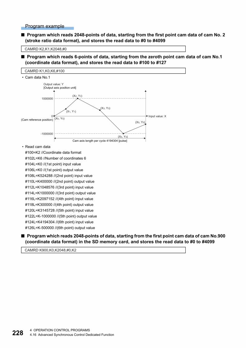
22
Program example
■ Program which reads 2048-points of data, starting from the first point cam data of cam No. 2 (stroke ratio data format), and stores the read data to #0 to #4099
■ Program which reads 6-points of data, starting from the zeroth point cam data of cam No.1 (coordinate data format), and stores the read data to #100 to #127
• Cam data No.1
• Read cam data
#100=K2 //Coordinate data format
#102L=K6 //Number of coordinates 6
#104L=K0 //(1st point) input value
#106L=K0 //(1st point) output value
#108L=K524288 //(2nd point) input value
#110L=K400000 //(2nd point) output value
#112L=K1048576 //(3rd point) input value
#114L=K1000000 //(3rd point) output value
#116L=K2097152 //(4th point) input value
#118L=K300000 //(4th point) output value
#120L=K3145728 //(5th point) input value
#122L=K-1000000 //(5th point) output value
#124L=K4194304 //(6th point) input value
#126L=K-500000 //(6th point) output value
■ Program which reads 2048-points of data, starting from the first point cam data of cam No.900 (coordinate data format) in the SD memory card, and stores the read data to #0 to #4099
CAMRD K2,K1,K2048,#0
CAMRD K1,K0,K6,#100
0 Input value: X(X0, Y0)(Cam reference position)
Output value: Y[Output axis position unit]
-1000000
Cam axis length per cycle 4194304 [pulse]
1000000
(X1, Y1)
(X2, Y2)
(X3, Y3)
(X4, Y4)
(X5, Y5)
CAMRD K900,K0,K2048,#0,K2
84 OPERATION CONTROL PROGRAMS4.16 Advanced Synchronous Control Dedicated Function

4
Cam data write: CAMWR
Setting data
■ Usable data: Usable
■ Description, data type of result
Processing details
• Of the cam data (stroke ratio data format, or coordinate data format) stored in the device specified with (S3) or later, the
data of the (n) number of points, starting from the cam data position specified with (S2), is written to the cam open area and
the write destination of the cam file specified with (D).
• Set the cam data first position specified with (S2) within the following range.
*1 Since the stroke ratio of the zeroth point cam data is fixed at 0%, the cam data cannot be write.
• For (n), specify the number of write points, starting from the cam data first position specified with (S2). Specify the number
of write points so that the device No. storing the end point data is within the range. If the number of write points, starting
from the first position, is outside the cam data range, an operation error occurs and the data is not written.
• The device No. specified with (S3) should be an even number. The write cam data is stored in the specified device
according to the cam data format as follows.
Format Number of basic steps Usable steps
F/FS G
CAMWR (S1), (S2), (n), (S3), (D) 16
Setting data
Bit device
Word device Constant Calculation expression
Bit conditional expression
Comparison conditional expression
16-bit integer type
32-bit integer type (L)
64-bit floating point type (F)
16-bit integer type(K/H)
32-bit integer type(K/H, L)
64-bit floating point type (K)
(S1)
(S2)
(n)
(S3)
(D)
Setting data Description Data type of result
(S1) Cam No. (1 to 1024)
(S2) Cam data first position
Stroke ratio data format: 1 to cam resolution
Coordinate data format: 0 to (Coordinate number-1)
(n) Number of cam data points
Stroke ratio data format: 1 to 32768
Coordinate data format: 1 to 16384
(S3) Start device No. which stores the writing cam data
(D) Cam file write destination (0000H to 0401H)
Data format First position range
Stroke ratio data format 1 to cam resolution*1
Coordinate data format 0 to (Coordinate number-1)
4 OPERATION CONTROL PROGRAMS4.16 Advanced Synchronous Control Dedicated Function 229

23
■ Stroke ratio data format
■ Coordinate data format
For coordinate data format, when writing is not completed in one attempt, divide the writing over several
attempts.
• During the execution of the CAMWR instruction, another CAMWR instruction, or CAMMK instruction cannot be processed.
During the execution of the CAMWR instruction, the "Cam data operation flag (SM505)" turns on. Therefore, create an
interlock. When the CAMWR instruction, or CAMMK instruction is executed while the "Cam data operation flag (SM505)" is
on, an error occurs.
The CAMWR instruction can be executed during the synchronous control. Note that the contents of the cam
data in operation are changed depending on the instruction execution timing.
Offset Item Range
+0 Can data format (Stroke ratio data format) 1
+1 Cam data starting point 0 to (Coordinate resolution-1)
+2 Cam resolution 256/512/1024/2048/4096/8192/16384/32768
+3
+4 Stroke ratio at first point cam data value -2147483648 to 2147483647[10-7%]
(-214.7483648 to 214.7483647[%])+5
+6 Stroke ratio at second point cam data value
+7
+(2N+2) Stroke ratio at Nth point cam data value
+(2N+3)
Offset Item Range
+0 Can data format (Coordinate data format) 2
+1 Unusable 0
+2 Coordinate number 2 to 65535
+3
+4 At first point cam data value Input value X1 0 to 2147483647
[Cam axis cycle unit]+5
+6 Output value Y1 -2147483648 to 2147483647
[Output axis position unit]+7
+8 At second point cam data value Input value X2 0 to 2147483647
[Cam axis cycle unit]+9
+10 Output value Y2 -2147483648 to 2147483647
[Output axis position unit]+11
+(4N) At Nth point cam data value Input value XN 0 to 2147483647
[Cam axis cycle unit]+(4N+1)
+(4N+2) Output value YN -2147483648 to 2147483647
[Output axis position unit]+(4N+3)
04 OPERATION CONTROL PROGRAMS4.16 Advanced Synchronous Control Dedicated Function

4
• Set the write to cam file, and the cam file write destination to (D).
• (D) can be omitted. When (D) is omitted, or is set outside the range, cam data is written to the cam open area only. When
performing write to cam file, set (D).
When "1: Write" is set to the write to cam file in (D), write to cam file is performed after completion of write to
the cam open area. When an error occurred during cam file operation, the cam data of the cam open area is
held.
• The following shows the operation for when the cam No. specified by (S1) already exists in the cam open area.
Operation error
An operation error will occur, and the cam data write will not be executed if:
• Cam No. specified with (S1) is outside the range of 1 to 1024. (Details code: 1)
• For cam data in the stroke ratio data format, the cam data first position specified with (S2) is outside the range of 1 to the
cam resolution. (Details code: 2)
• For cam data in the coordinate data format, the cam data first position specified with (S2) is outside the range of 0 to
(coordinate number - 1). (Details code: 2)
• For cam data in the stroke ratio data format, the number of cam data points is outside the range of 1 to 32768 (Details code:
3).
• For cam data in the coordinate data format, the number of cam data points is outside the range of 1 to 16384. (Details code:
3)
• The start position and the number of cam data points, which are outside the range of the cam resolution or the number of
coordinates, are set. (Details code: 3)
• The device numbers storing the number of cam data points specified with (n) are outside the range. (Details code: 4)
• (S3) is not an even-numbered device. (Details code: 5)
• Cam data format specified with (S3) is set to other than 1 or 2. (Details code: 6)
• For cam data in the stroke ratio data format, the cam resolution is set a value other than "256/512/1024/2048/4096/8192/
16384/32768". (Details code: 7)
• For cam data in the coordinate data format, the coordinate number is set a value other than "2 to 65535". (Details code: 7)
• For cam data in the stroke ratio data format, the cam data first position is outside the range of 0 to (cam resolution - 1).
(Details code: 8)
• The writable area is insufficient when the cam data is being written. (Details code: 10)
• The input value of the coordinate data is a negative value. (Details code: 11)
• The input value of the coordinate data satisfies "Xn > Xn+1". (Details code: 11)
• The CAMWR instruction is executed while the "Cam data operation flag (SM505)" is ON. (Details code: 13)
In the following cases an operation error occurs, and the write to cam file is not performed. (Write to the cam open area is
performed)
• The CAMWR instruction was executed for a cam change data cam file. (Details code: 18)
• An error occurred during cam file access. (Details code: 19)
• When the cam data format, and resolution/number of coordinates are the same, the existing cam data is overwritten.
• When the cam data format, or resolution/number of coordinates are different, the existing cam data is erased.
(When the points of cam data are low due to resolution/number of coordinates, the cam data for sections where write was not performed become unfixed.)
b0b15
Write to cam file0: Do not write1: Write (Stroke ratio data/Coordinate data)Cam file write destination2: SD memory card4: Standard ROM
4 OPERATION CONTROL PROGRAMS4.16 Advanced Synchronous Control Dedicated Function 231

23
Program example
■ Program which writes the data stored in #0 to #4099 to the 2048-point area, starting from the first point cam data, of cam No. 256 (stroke ratio data format)
■ Program (Cam axis length per cycle = 4194304) which writes the data stored in #0 to #27 to the 6-point area, starting from the zeroth point cam data, of cam No. 255 (coordinate data format)
CAMWR K256,K1,K2048,#0
#0=K2 //Coordinate data format#2L=K6 //Number of coordinates 6#4L=K0 //(1st point) input value#6L=K0 //(1st point) output value#8L=K524288 //(2nd point) input value#10L=K400000 //(2nd point) output value#12L=K1048576 //(3rd point) input value#14L=K1000000 //(3rd point) output value#16L=K2097152 //(4th point) input value#18L=K300000 //(4th point) output value#20L=K3145728 //(5th point) input value#22L=K-1000000 //(5th point) output value#24L=K4194304 //(6th point) input value#26L=K-500000 //(6th point) output valueCAMWR K255,K0,K6,#0 //Cam data write
0 Input value: X(X0, Y0)(Cam reference position)
Output value: Y[Output axis position unit]
-1000000
Cam axis length per cycle 4194304[pulse]
1000000
(X1, Y1)
(X2, Y2)
(X3, Y3)
(X4, Y4)
(X5, Y5)
24 OPERATION CONTROL PROGRAMS4.16 Advanced Synchronous Control Dedicated Function

4
Cam auto-generation: CAMMK
Setting data
■ Usable data: Usable
■ Description, data type of result
Processing details
• The auto-generation cam No. data specified with (S1) is created in the cam open area, and the cam file writing destination
specified with (D), based on the cam auto-generation type specified with (S2), and the auto-generation data to be stored in
the device specified with (S3). By specifying standard ROM to (D), the cam auto-generation will be automatically executed
at next power supply ON of the Multiple CPU system.
• Specify the following cam auto-generation type with (S2).
• For (S3), set the auto-generation data for the cam auto-generation type specified with (S2). The specified device No.
should be an even number. Assign the auto-generation data to the specified device or later. The device No. storing the end
point data must be within the range.
• During the execution of the CAMMK instruction, another CAMWR instruction or CAMMK instruction cannot be processed.
During the execution of the CAMMK instruction, the "Cam data operation flag (SM505)" turns on. Therefore, create an
interlock. When the CAMWR instruction or CAMMK instruction is executed while the "Cam data operation flag (SM505)" is
ON, an error occurs.
Format Number of basic steps Usable steps
F/FS G
CAMMK (S1), (S2), (S3), (D) 13
Setting data
Bit device
Word device Constant Calculation expression
Bit conditional expression
Comparison conditional expression
16-bit integer type
32-bit integer type (L)
64-bit floating point type (F)
16-bit integer type(K/H)
32-bit integer type(K/H, L)
64-bit floating point type (K)
(S1)
(S2)
(S3)
(D)
Setting data Description Data type of result
(S1) Cam No. (1 to 1024)
(S2) Cam auto-generation type
Cam for rotary cutter: 1
Easy stroke ratio cam: 2
Advanced stroke ratio cam: 3
(S3) Start device No. which stores the auto-generation data
(D) Cam file write destination (0000H to 0401H)
Cam auto-generation type Setting value
Cam for rotary cutter 1
Easy stroke ratio cam 2
Advanced stroke ratio cam 3
4 OPERATION CONTROL PROGRAMS4.16 Advanced Synchronous Control Dedicated Function 233

23
• Set the write to cam file, and the cam file write destination to (D). When write to cam file is "0: Do not write", write to cam
open area is performed only, and cam data is not written to the cam file.
• (D) can be omitted. When (D) is omitted, or is set outside the range, cam data is written to the cam open area only. When
performing write to cam file, set (D).
When "1: Write" is set to the write to cam file in (D), write to cam file is performed after completion of write to
the cam open area. When an error occurred during cam file operation, the cam data of the cam open area is
retained.
Operation error
An operation error will occur, and the cam auto-generation will not be executed if:
• Cam No. specified with (S1) is outside the range of 1 to 1024. (Details code: 1)
• Auto-generation type specified with (S2) is set to a value that does not correspond to an auto-generation type. (Details
code: 2)
• The device numbers storing the auto-generation data specified with (S3) are outside the range. (Details code: 5)
• (S3) is not an even-numbered device. (Details code: 6)
• The writable area is insufficient when the cam data is being written. (Details code: 4)
• A value outside the range is set for the auto-generation data. (Details code: 7)
• For the cam for rotary cutter, a value has been set as "sheet synchronization width sheet length" in the auto-generation
parameter. (Details code: 8)
• For the cam for rotary cutter, the asynchronous speed will be reduced when the auto-generation data is set as
"synchronous axis length (synchronous axis diameter ") < sheet length". (Details code: 9)
• For the cam for rotary cutter, the asynchronous speed is 655.35 times of larger than synchronous speed by auto-generation
data. (Details code: 10)
• The CAMMK instruction is executed while the "Cam data operation flag (SM505)" is ON. (Details code: 12)
• For the easy stroke ratio cam or advanced stroke ratio cam, the end point set for each section are not in ascending order.
(Details code: 20)
• For the easy stroke ratio cam or advanced stroke ratio cam, the end point of the final section is less than the cam axis
length per cycle. (Details code: 21)
• The curve applicable range (P1, P2) or acceleration/deceleration range compensation (L1, L2) in advanced stroke ratio
cam are wrong. (Details code: 23)
• The stroke and stroke amount for each section in advanced stroke ratio cam are wrong. (Details code: 7)
In the following cases an operation error occurs, and the write to cam file is not performed. (Write to the cam open area is
performed)
• The CAMMK instruction was executed for a cam change data cam file. (Details code: 18)
• An error occurred during cam file access. (Details code: 19)
b0b15
Write to cam file0: Do not write1: Write (Auto-generation data format)Cam file write destination2: SD memory card4: Standard ROM
44 OPERATION CONTROL PROGRAMS4.16 Advanced Synchronous Control Dedicated Function

4
Cam for rotary cutterSet the auto-generation data of the rotary cam cutter. (sheet length, synchronization width, etc.)
Synchronous axis cycle length/diameter
Synchronous speed(Feed sheet speed)
Cam stroke ratio(Cam data by auto-generation)
-: The synchronous section is adjusted to the sheet start side.0: The center of the sheet is in the synchronous section.+: The synchronous section is adjusted to the sheet end side.
Cam axis current value per cycle
Cam axis (Synchronous axis) speed
t
t
t
Sheet synchronization width
Sheet synchronization width
Synchronous position adjustment
Acceleration/deceleration width
Feed sheet
Synchronous axis length
Sheet length
Sheet length
Acceleration/deceleration width
Acceleration/deceleration width
100%
Asynchronous speed(Automatically calculated)
When 0%, it is as fast assynchronous speed.
Synchronous section acceleration ratio
Synchronousaxis
4 OPERATION CONTROL PROGRAMS4.16 Advanced Synchronous Control Dedicated Function 235

23
■ Device assignment of the cam auto-generation data for the rotary cutter camWhen the synchronous position adjustment is set to 0, the cam pattern of which the sheet center is in the synchronous section
is created.
Offset Name Description Range
+0 Resolution Set the cam resolution for generating the cam. 256/512/1024/2048/4096/8192/
16384/32768+1
+2 Auto-generation option • Select the trapezoidal acceleration/deceleration system or the S-curve
acceleration/deceleration system with bit 0.
• Select the diameter or the cycle length for the synchronous axis length with bit
1.
• Set 0 for bits 2 to 15.
• Bit 0: Acceleration/deceleration
system
0: Trapezoidal acceleration/
deceleration
1: S-curve acceleration/
deceleration
• Bit 1: Synchronous axis length
setting
0: Diameter
1: Cycle length
+3 Synchronous section
acceleration ratio
Set when the synchronous speed in the synchronous section needs to be
adjusted.
The speed is "Synchronous speed (100% + Acceleration ratio)" in the
synchronous section.
-5000 to 5000[0.01%]
+4 Sheet length Set the sheet length. 1 to 2147483647
[(Optional) Same units]+5
+6 Sheet synchronization
width
• Set the sheet synchronization width (seal width).
• When the synchronous speed section for retracting is required in front of and
behind the sheet synchronization width, add the retracting width.
1 to 2147483647
[(Optional) Same units]+7
+8 Synchronous axis length • Set the rotary cutter axis length.
• When the synchronous axis length of the auto-generation option is set to the
diameter, "Cycle length = setting value .
• When the synchronous axis length of the auto-generation option is set to the
cycle length, "Cycle length = setting value".
• For diameter setting
1 to 680000000
• For cycle length setting
1 to 2147483647
[(Optional) Same units]
+9
+10 Synchronous position
adjustment
• Set the position adjustment of the synchronous section.
-: The synchronous section is adjusted to the sheet start side.
0: The center of the sheet is in the synchronous section.
+: The synchronous section is adjusted to the sheet end side.
• Set the value within one-half of the sheet length.
-1073741823 to 1073741823
[(Optional) Same units]+11
+12 Acceleration/
deceleration width
• Set the sheet width (one side) of the acceleration/deceleration area.
• When a negative value is set, the acceleration/deceleration width is
determined to be the maximum.
0 to 2147483647
[(Optional) Same units]
• For a value other than the
above, the acceleration/
deceleration width is
determined to be the maximum.
+13
+14 Number of cutter Set the number of cutter. 1 to 256
+15 Asynchronous speed
result
When the cam auto-generation is successfully performed, the asynchronous
speed is stored as the ratio to the synchronous speed.
0 to 65535 [0.01 times]
64 OPERATION CONTROL PROGRAMS4.16 Advanced Synchronous Control Dedicated Function

4
■ Program examplesProgram which creates cam data (resolution: 512) for the rotary cutter operation pattern in Cam No.5.
Easy stroke ratio cam/Advanced stroke ratio camCam data can be automatically generated without using the cam data setting of MT Developer2 by setting the stroke amount
and sections. In easy stroke ratio cam, detailed coefficients of the cam curve are omitted and the curves and number of
sections that can be used are limited. With the current value per cycle "0" as starting point, automatically generates cam data
from the stroke and cam curve type of each section until the specified end point (cam axis current value per cycle).
Feed sheetR
etra
ctin
gse
ctio
n
Acceleration/deceleration width = 55.0mm
Acceleration/deceleration width = 55.0mm
Synchronous axis length = 100.0mm (Diameter)
Sheet length = 200.0mm
(The retracting section is adjusted to the sheet end side.)Synchronous position adjustment = 20.0mm
Sheet synchronization width = 30.0mm+20.0mm
Cam axis (Synchronous axis) speed
t
Synchronous speed(Feed sheet speed)
Center of sheet
Asynchronous speed
Synchronous section acceleration ratio = 3.00%
D5000L=K512 // Resolution = 512D5002=K0 // Acceleration/deceleration system = Trapezoidal, Synchronous axis length setting = DiameterD5003=K300 // Synchronous section acceleration ratio = 3.00%D5004L=K2000 // Sheet length = 200.0mmD5006L=K500 // Sheet synchronization width = 30.0mm (Seal section) + 20.0mm (Retracting operation)D5008L=K1000 // Synchronous axis length = 100.0mm(Diameter)D5010L=K200 // Synchronous position adjustment = 20.0mmD5012L=K550 // Acceleration/deceleration width = 55.0mmD5014=K1 // Number of cutter = 1CAMMK K5,K1,D5000 // Cam auto-generation (Asynchronous speed result is stored in D5015.)
Synchronousaxis
Sea
lse
ctio
n
0 End point: X(Cam reference position)
Stroke: Y [Optional unit]
-2147483648
Cam axis length per cycle
2147483647(X1, Y1)
(X4, Y4)
(X2, Y2)
(X3, Y3)
(X5, Y5)
(Xnumber of section, Y number of section)
Section 1 Section2
Section 3 Section 4 Section 5
4 OPERATION CONTROL PROGRAMS4.16 Advanced Synchronous Control Dedicated Function 237

23
■ Device assignment of the cam auto-generation data • Easy stroke ratio cam data for auto-generation
*1 The set value is only used for cam data generation. Control is performed by the output axis parameter "[Pr.439] Cam axis length per cycle (R: D42700+160n, D42701+160n/Q: D15060+150n, D15061+150n)".
*2 Refer to the cam curve list for the shapes of each cam type. (Page 241 Cam curve list) Use P1 = 0, P2 = 1.00, and default values for L1 and L2.
*3 If setting is outside range, the cam axis length per cycle will be set as the final end point of the section settings.
Offset Name Description Range
+0 Resolution Set the cam resolution for generating the cam. 256/512/1024/2048/4096/ 8192/
16384/32768+1
+2 Cam axis length per cycle*1 Set the cycle length of one cam operation cycle. 1 to 2147483647
[Cam axis length per cycle units]+3
+4 Cam data starting point Set the starting point as the point corresponding to "cycle length=0" of cam
data.
0 to (Resolution - 1)
+5
+6 Number of sections Set the number of sections of cam data.
Set data for the number of sections specified.
1 to 32
+7 Unusable Set 0. 0
+8 Section
1
Cam curve type*2 Set the cam curve. 0: Constant speed
1: Constant acceleration
2: Distorted trapezoid
3: Distorted sine
4: Distorted constant speed
5: Cycloid
6: 5th curve
+9 Unusable Set 0. 0
+10 End point (X1) Set the point for cam axis length per cycle (cam axis current value per cycle).
It is necessary to set a value larger than the end point immediately before
(Xn<Xn+1). Also, for the final end point, set as the cam axis length per cycle.
1 to Cam axis length per cycle
[Cam axis length per cycle units]*3+11
+12 Stroke (Y1) Set the stroke position from the cam reference position of when at the end
point specified by cam axis current value per cycle.
When set at 1000000000, it becomes the position set in "[Pr.441] Cam stroke
amount (R: D42704+160n, D42705+160n/Q: D15064+150n, D15065+150n)".
-2147483648 to 2147483647
[0.0000001%]+13
+14 Section
2
Cam curve type*2 The data specified by "number of sections" becomes valid.
It is not necessary to set the data after the specified number of sections.
0: Constant speed
1: Constant acceleration
2: Distorted trapezoid
3: Distorted sine
4: Distorted constant speed
5: Cycloid
6: 5th curve
+15 Unusable 0
+16 End point(X2) 1 to Cam axis length per cycle
[Cam axis length per cycle units]*3+17
+18 Stroke (Y2) -2147483648 to 2147483647
[0.0000001%]+19
+194 Section
32
Cam curve type*2 0: Constant speed
1: Constant acceleration
2: Distorted trapezoid
3: Distorted sine
4: Distorted constant speed
5: Cycloid
6: 5th curve
+195 Unusable 0
+196 End point (X32) 1 to Cam axis length per cycle
[Cam axis length per cycle units]*3+197
+198 Stroke (Y32) -2147483648 to 2147483647
[0.0000001%]+199
84 OPERATION CONTROL PROGRAMS4.16 Advanced Synchronous Control Dedicated Function

4
• Advanced stroke ratio cam data for auto-generation
Offset Name Description Range
+0 Resolution Set the cam resolution for generating the cam. 256/512/1024/2048/4096/ 8192/
16384/32768+1
+2 Cam axis length per cycle*1 Set the cycle length of one cam operation cycle. 1 to 2147483647
[Cam axis length per cycle units]+3
+4 Cam stroke amount*1 Set the reference value for the stroke amount specified by stroke (Yn).
When the cam stroke amount units are "%", this is ignored.
1 to 2147483647
[Cam stroke amount units]+5
+6 Unit setting Set the display unit of the cam axis length per cycle, and the unit for cam
stroke amount in hexadecimal. When a value outside the range is set, cam
data is generated from the default value (7952H).
+7 Unusable Set 0. 0
+8 Cam data starting point Set the starting point as the point corresponding to "cycle length=0" of cam
data.
0 to (Resolution - 1)
+9
+10 Number of sections Set the number of sections of cam data. Set data for the number of sections
specified.
1 to 360
+11 Unusable Set 0. 0
+12 Section
1
Cam curve type*2 Set the cam curve. 0: Constant speed
1: Constant acceleration
2: Distorted trapezoid
3: Distorted sine
4: Distorted constant speed
5: Cycloid
6: 5th curve
7: Trapecloid
8: Reverse trapecloid
9: Double hypotenuse
10: Reverse double hypotenuse
11: Single hypotenuse
+13 Unusable Set 0. 0
+14 End point (X1) Set the point for cam axis length per cycle (cam axis current value per cycle).
It is necessary to set a value larger than the end point immediately before
(Xn<Xn+1). Also, for the final end point, set as the cam axis length per cycle.
1 to Cam axis length per cycle
[Cam axis length per cycle units]*3+15
+16 Stroke (Y1)*4 Set the stroke position from the cam reference position of when at the end
point specified by cam axis current value per cycle.
When set at 1000000000, it becomes the position set in "[Pr.441] Cam stroke
amount (R: D42704+160n, D42705+160n/Q: D15064+150n, D15065+150n)".
-2147483648 to 2147483647
[Cam stroke units]+17
+18 Curve applicable
range (P1)
Set the curve applicable range (start point: P1, end point: P2) for the cam
curve. Set so that "P1<P2". When "P1=P2=0", "P2=0" is applied.
0 to 100 [0.01]
+19 Curve applicable
range (P2)
+20 Acceleration/
deceleration range
compensation
(Range L1)*2
Set the acceleration/deceleration range (L1, L2) for the cam curve. The range
that can be set differs depending on the cam curve. When "L1=L2=0", the
default value for each curve is applied.
1 to 9999 [0.0001]
+21 Acceleration/
deceleration range
compensation
(Range L2)*2
H����
Cam axis length percycle units (Display) 0: mm 1: inch 2: degree 3: pulseNumber of decimalplaces 0 to 9Cam stroke amountunits 0: mm 1: inch 2: degree 3: pulse 9: %Number of decimalplaces 0 to 9
4 OPERATION CONTROL PROGRAMS4.16 Advanced Synchronous Control Dedicated Function 239

24
+22 Section
2
Cam curve type*2 The data specified by "number of sections" becomes valid.
It is not necessary to set the data after the specified number of sections.
0: Constant speed
1: Constant acceleration
2: Distorted trapezoid
3: Distorted sine
4: Distorted constant speed
5: Cycloid
6: 5th curve
7: Trapecloid
8: Reverse trapecloid
9: Double hypotenuse
10: Reverse double hypotenuse
11: Single hypotenuse
+23 Unusable 0
+24 End point (X2) 1 to Cam axis length per cycle
[Cam axis length per cycle units]*3+25
+26 Stroke (Y2)*4 -2147483648 to 2147483647
[Cam stroke units]+27
+28 Curve applicable
range (P1)
0 to 100 [0.01]
+29 Curve applicable
range (P2)
+30 Acceleration/
deceleration range
compensation
(Range L1)*2
1 to 9999 [0.0001]
+31 Acceleration/
deceleration range
compensation
(Range L2)*2
+3602 Section
360
Cam curve type*2 0: Constant speed
1: Constant acceleration
2: Distorted trapezoid
3: Distorted sine
4: Distorted constant speed
5: Cycloid
6: 5th curve
7: Trapecloid
8: Reverse trapecloid
9: Double hypotenuse
10: Reverse double hypotenuse
11: Single hypotenuse
+3603 Unusable 0
+3604 End point (X32) 1 to Cam axis length per cycle
[Cam axis length per cycle units]*3+3605
+3606 Stroke (Y32)*4 -2147483648 to 2147483647
[Cam stroke units]+3607
+3608 Curve applicable
range (P1)
0 to 100 [0.01]
+3609 Curve applicable
range (P2)
+3610 Acceleration/
deceleration range
compensation
(Range L1)*2
1 to 9999 [0.0001]
+3611 Acceleration/
deceleration range
compensation
(Range L2)*2
Offset Name Description Range
04 OPERATION CONTROL PROGRAMS4.16 Advanced Synchronous Control Dedicated Function
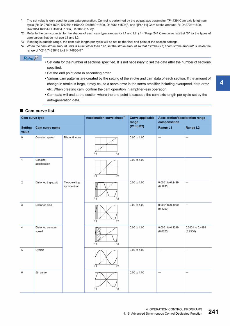
4
*1 The set value is only used for cam data generation. Control is performed by the output axis parameter "[Pr.439] Cam axis length per cycle (R: D42700+160n, D42701+160n/Q: D15060+150n, D15061+150n)", and "[Pr.441] Cam stroke amount (R: D42704+160n, D42705+160n/Q: D15064+150n, D15065+150n)".
*2 Refer to the cam curve list for the shapes of each cam type, ranges for L1 and L2. (Page 241 Cam curve list) Set "0" for the types of cam curves that do not use L1 and L2.
*3 If setting is outside range, the cam axis length per cycle will be set as the final end point of the section settings.*4 When the cam stroke amount units is a unit other than "%", set the stroke amount so that "Stroke (Yn) / cam stroke amount" is inside the
range of "-214.7483648 to 214.7483647"
• Set data for the number of sections specified. It is not necessary to set the data after the number of sections
specified.
• Set the end point data in ascending order.
• Various cam patterns are created by the setting of the stroke and cam data of each section. If the amount of
change in stroke is large, it may cause a servo error in the servo amplifier including overspeed, data error
etc. When creating cam, confirm the cam operation in amplifier-less operation.
• Cam data will end at the section where the end point is exceeds the cam axis length per cycle set by the
auto-generation data.
■ Cam curve list
Cam curve type Acceleration curve shape*1 Curve applicable range(P1 to P2)
Acceleration/deceleration range compensation
Setting value
Cam curve name Range L1 Range L2
0 Constant speed Discontinuous 0.00 to 1.00
1 Constant
acceleration
0.00 to 1.00
2 Distorted trapezoid Two-dwelling
symmetrical
0.00 to 1.00 0.0001 to 0.2499
(0.1250)
3 Distorted sine 0.00 to 1.00 0.0001 to 0.4999
(0.1250)
4 Distorted constant
speed
0.00 to 1.00 0.0001 to 0.1249
(0.0625)
0.0001 to 0.4999
(0.2500)
5 Cycloid 0.00 to 1.00
6 5th curve 0.00 to 1.00
P1 P2
P1 P2
P1 P2
P1 P2
P1 P2
P1 P2
P1 P2
4 OPERATION CONTROL PROGRAMS4.16 Advanced Synchronous Control Dedicated Function 241

24
*1 : Stroke ratio : Acceleration : Range L1 : Range L2
7 Trapecloid Two-dwelling
asymmetrical
0.00 to 1.00 0.0001 to 0.2499
(0.1250)
8 Reverse trapecloid 0.00 to 1.00 0.0001 to 0.2499
(0.1250)
9 Double hypotenuse One-dwelling 0.00 to 1.00
10 Reverse double
hypotenuse
0.00 to 1.00
11 Single hypotenuse Non-dwelling
curve
0.00 to 1.00
Cam curve type Acceleration curve shape*1 Curve applicable range(P1 to P2)
Acceleration/deceleration range compensation
Setting value
Cam curve name Range L1 Range L2
P1 P2
P1 P2
P1 P2
P1 P2
P1 P2
24 OPERATION CONTROL PROGRAMS4.16 Advanced Synchronous Control Dedicated Function

4
■ Program that creates easy stroke ratio cam data • Program which creates cam data (resolution: 512) in cam No. 5
D5000L=K512 //Resolution=512D5002L=K36000000 //Cam axis length per cycle=360.0[degree]D5004L=K0 //Cam data starting point=0th pointD5006=K7 //Number of sections=7 sectionsD5007=K0 //UnusableD5008=K0 //(Section 1) Cam curve type=Constant speedD5009=K0 //UnusableD5010L=K9000000 //(Section 1) End point (X1)=90.0[degree]D5012L=K1000000000 //(Section 1) Stroke (Y1)=100.0[%]D5014=K0 //(Section 2) Cam curve type=Constant speedD5015=K0 //UnusableD5016L=K12000000 //(Section 2) End point (X2)=120.0[degree]D5018L=K1000000000 //(Section 2) Stroke (Y2)=100.0[%]D5020=K0 //(Section 3) Cam curve type=Constant speedD5021=K0 //UnusableD5022L=K15000000 //(Section 3) End point (X3)=150.0[degree]D5024L=K700000000 //(Section 3) Stroke (Y3)=70.0[%]D5026=K0 //(Section 4) Cam curve type=Constant speedD5027=K0 //UnusableD5028L=K21000000 //(Section 4) End point (X4)=210.0[degree]D5030L=K700000000 //(Section 4) Stroke (Y4)=70.0[%]D5032=K0 //(Section 5) Cam curve type=Constant speedD5033=K0 //UnusableD5034L=K24000000 //(Section 5) End point (X5)=240.0[degree]D5036L=K1000000000 //(Section 5) Stroke (Y5)=100.0[%]D5038=K0 //(Section 6) Cam curve type=Constant speedD5039=K0 //UnusableD5040L=K27000000 //(Section 6) End point (X6)=270.0[degree]D5042L=K1000000000 //(Section 6) Stroke (Y6)=100.0[%]D5044=K0 //(Section 7) Cam curve type=Constant speedD5045=K0 //UnusableD5046L=K36000000 //(Section 7) End point (X7)=360.0[degree]D5048L=K0 //(Section 7) Stroke (Y7)=0[%]CAMMK K5,K2,D5000 //Cam auto-generation
090
70[%]
End point: X
Cam stroke amount (Y)
100[%]Section 1 Section 7
Section2
Section3
Section5
Section6Section 4
Cam axis length per cycle 360.00000[degree]120 150 210 240 270
4 OPERATION CONTROL PROGRAMS4.16 Advanced Synchronous Control Dedicated Function 243

24
• Program which creates cam data (resolution: 512) in cam No. 6
D6000L=K512 //Resolution=512D6002L=K36000000 //Cam axis length per cycle=360.0[degree]D6004L=K0 // Cam data starting point=0th pointD6006=K5 //Number of sections=5 sectionsD6007=K0 //UnusableD6008=K0 //(Section 1) Cam curve type=Constant speedD6009=K0 //UnusableD6010L=K9000000 //(Section 1) End point (X1)=90.0[degree]D6012L=K0 //(Section 1) Stroke (Y1)=0[%]D6014=K0 //(Section 2) Cam curve type=Constant speedD6015=K0 //UnusableD6016L=K17000000 //(Section 2) End point (X2)=170.0[degree]D6018L=K800000000 //(Section 2) Stroke (Y2)=80[%]D6020=K0 //(Section 3) Cam curve type=Constant speedD6021=K0 //UnusableD6022L=K19000000 //(Section 3) End point (X3)=190.0[degree]D6024L=K800000000 //(Section 3) Stroke (Y3)=80[%]D6026=K0 //(Section 4) Cam curve type=Constant speedD6027=K0 //UnusableD6028L=K27000000 //(Section 4) End point (X4)=270.0[degree]D6030L=K0 //(Section 4) Stroke (Y4)=0[%]D6032=K0 //(Section 5) Cam curve type=Constant speedD6033=K0 //UnusableD6034L=K36000000 //(Section 5) End point (X5)=360.0[degree]D6036L=K0 //(Section 5) Stroke (Y5)=0[%]CAMMK K6,K2,D6000 //Cam auto-generation
090
End point: X
Cam stroke amount (Y)
Section 1 Section 5Section 2 Section 4Section
3
Cam axis length per cycle 360.00000[degree]
80[%]
170 190 270
44 OPERATION CONTROL PROGRAMS4.16 Advanced Synchronous Control Dedicated Function

4
Cam position calculation: CAMPSCL
Setting data
■ Usable data: Usable
■ Description, data type of result
Processing details
• For the cam No. data specified with (S1), the cam axis current feed value or the cam axis current value per cycle is
calculated from the cam position calculation control data specified with (S2), and the value is output to the device specified
with (D).
• Specify the cam No. to perform the cam position calculation with (S1). When cam No. 0 is specified, the cam position is
calculated as the linear cam. For cam No.1 to 1024, the cam position is calculated with the cam data on the cam open area.
• The device No. specified with (S2) should be an even number. Set the cam position calculation control data in the specified
device as follows.
■ Device assignment of the cam position calculation control data
Format Number of basic steps Usable steps
F/FS G
CAMPSCL (S1), (S2), (D) 12
Setting data
Bit device
Word device Constant Calculation expression
Bit conditional expression
Comparison conditional expression
16-bit integer type
32-bit integer type (L)
64-bit floating point type (F)
16-bit integer type(K/H)
32-bit integer type(K/H, L)
64-bit floating point type (K)
(S1)
(S2)
(D)
Setting data Description Data type of result
(S1) Cam position calculation: Cam No. (0 to 1024)
(S2) Start device No. which stores the cam position calculation control data
(D) Device No. which stores the cam position calculation result
Offset Name Description Range
+0 Cam position calculation
type
Specify the cam axis current feed value calculation/cam axis current value per
cycle calculation
0: Cam axis current feed value
calculation
1: Cam axis current value per
cycle calculation
+1 Unusable Set 0. 0
+2 Cam stroke amount Set the cam stroke amount for the cam position calculation. -2147483648 to 2147483647
[Output axis position units]+3
+4 Cam axis length per
cycle
Set the cam axis length per cycle for the cam position calculation. 1 to 2147483647
[Cam axis cycle unit]+5
+6 Cam reference position Set the cam reference position for the cam position calculation. -2147483648 to 2147483647
[Output axis position units]+7
+8 Cam axis current value
per cycle
• Set the cam axis current value per cycle for the cam position calculation when
calculating the cam axis current feed value.
• Set the cam axis current value per cycle as the starting point to search when
calculating the cam axis current value per cycle and the cam position.
0 to (Cam axis length per cycle)
[Cam axis cycle unit]+9
+10 Cam axis current feed
value
Set the cam axis current feed value for the cam position calculation when
calculating the cam axis current value per cycle. (This is not used when the cam
position calculation type is set to the cam axis current feed value calculation.)
-2147483648 to 2147483647
[Output axis position units]+11
4 OPERATION CONTROL PROGRAMS4.16 Advanced Synchronous Control Dedicated Function 245

24
• Specify the device No. with (D) to an even number. The specified device stores the cam position calculation result as shown
below when the calculation is completed.
• The cam position calculation does not update the cam reference position automatically.
Operation error
An operation error will occur, and the cam position calculation will not be executed if:
• Cam No. specified with (S1) is outside the range of 0 to 1024. (Details code: 1)
• The cam No. data specified with (S1) does not exist in the cam open area. (Details code: 2)
• The device numbers storing the cam position calculation control data specified with (S2) are outside the range. (Details
code: 3)
• (S2) is not an even-numbered device. (Details code: 4)
• Cam position calculation type specified with cam position calculation control data is set to other than 0 or 1. (Details code:
5)
• Cam axis length per cycle is outside the range of 1 to 2147483647. (Details code: 6)
• Cam axis current value per cycle is outside the range of 0 to (cam axis length per cycle). (Details code: 7)
• The device numbers storing the cam position calculation result specified with (D) are outside the range. (Details code: 8)
• (D) is not an even-numbered device. (Details code: 9)
• The cam axis current value per cycle cannot be calculated by the cam axis current value per cycle calculation. (Details
code: 10)
Program example
■ Program which calculates the cam axis current feed value in the linear cam pattern (cam No. 0)
Cam position calculation Description
Cam axis current feed value
calculation
The cam axis current feed value that is calculated within the following range is stored.
-2147483648 to 2147483647 [Output axis position units]
Cam axis current value per cycle
calculation
The cam axis current value per cycle that is calculated within the following range is stored.
0 to (Cam axis length per cycle-1) [Cam axis cycle unit]
[G10]
END
Cam (Linear)
[F10] //Cam position calculation data setD10000=K0 //Cam position calculation type= Cam axis current feed value calculationD10001=K0 //UnusableD10002L=K2097152L //Cam stroke amount= 2097152[pulse]D10004L=K4194304L //Cam axis length per cycle= 4194304[pulse]D10006L=K0L //Cam reference position=0[pulse]D10008L=K2097152L //Cam axis current value per cycle= 2097152[pulse]D10010L=K0L //Cam axis current feed value= 0 (The setting is not required.)
X0 //Standby until X0 turns ON
[F20] //Cam position calculation for cam No.0 (The result is stored in W1F00L.)CAMPSCL K0,D10000,W1F00L
Cam axis current value per cycle2097152[pulse]
Cam axis length per cycle4194304[pulse]
Cam stroke amount2097152[pulse]
Cam axis currentvalue feed value1048576[pulse]
Cam referenceposition0[pulse]
64 OPERATION CONTROL PROGRAMS4.16 Advanced Synchronous Control Dedicated Function
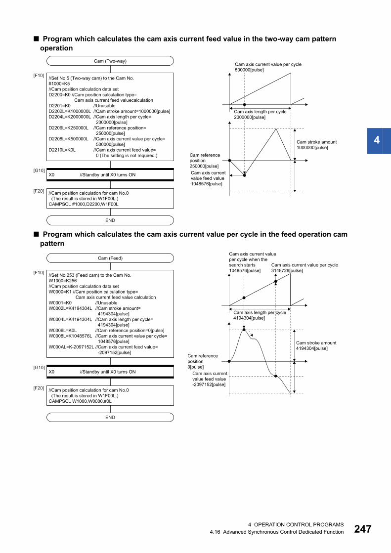
4
■ Program which calculates the cam axis current feed value in the two-way cam pattern operation
■ Program which calculates the cam axis current value per cycle in the feed operation cam pattern
Cam axis current value per cycle500000[pulse]
Cam axis length per cycle2000000[pulse]
Cam stroke amount1000000[pulse]
Cam referenceposition 250000[pulse]Cam axis currentvalue feed value1048576[pulse]
[G10]
END
Cam (Two-way)
[F10] //Set No.5 (Two-way cam) to the Cam No.#1000=K5//Cam position calculation data setD2200=K0 //Cam position calculation type= Cam axis current feed valuecalculationD2201=K0 //UnusableD2202L=K1000000L //Cam stroke amount=1000000[pulse]D2204L=K2000000L //Cam axis length per cycle= 2000000[pulse]D2206L=K250000L //Cam reference position= 250000[pulse]D2208L=K500000L //Cam axis current value per cycle= 500000[pulse]D2210L=K0L //Cam axis current feed value= 0 (The setting is not required.)
X0 //Standby until X0 turns ON
[F20] //Cam position calculation for cam No.0 (The result is stored in W1F00L.)CAMPSCL #1000,D2200,W1F00L
Cam axis current value per cycle3148728[pulse]
Cam axis currentvalue feed value-2097152[pulse]
Cam axis current valueper cycle when thesearch starts1048576[pulse]
Cam axis length per cycle4194304[pulse]
Cam stroke amount4194304[pulse]
Cam referenceposition 0[pulse][G10]
END
Cam (Feed)
[F10] //Set No.253 (Feed cam) to the Cam No.W1000=K256//Cam position calculation data setW0000=K1 //Cam position calculation type= Cam axis current feed value calculationW0001=K0 //UnusableW0002L=K4194304L //Cam stroke amount= 4194304[pulse]W0004L=K4194304L //Cam axis length per cycle= 4194304[pulse]W0006L=K0L //Cam reference position=0[pulse]W0008L=K1048576L //Cam axis current value per cycle= 1048576[pulse]W000AL=K-2097152L //Cam axis current feed value= -2097152[pulse]
X0 //Standby until X0 turns ON
[F20] //Cam position calculation for cam No.0 (The result is stored in W1F00L.)CAMPSCL W1000,W0000,#0L
4 OPERATION CONTROL PROGRAMS4.16 Advanced Synchronous Control Dedicated Function 247

24
4.17 Vision System Dedicated Function
Open line: MVOPEN
Setting data
■ Usable data: Usable
■ Description, data type of result
Processing details
• The vision system specified with (S1) is logged on.
• The Motion SFC program execution transits to the next block without waiting for the completion on the vision system logon.
After process completion, the status storage device value set in the Ethernet communication line setting parameter is 20
(reception enable).
• (S2) is set in increments of 10ms. When the setting is omitted, the timeout time is 10 seconds (same as setting 1000).
Operation error
An operation error will occur if:
• The (S1) data is outside the range of 1 to 32.
• The (S2) data is outside the range of 1 to 32767.
• MVOPEN is executed again for the vision system that has been logged on.
• The vision system parameter setting is different from the setting on the vision system.
• The logon is not completed when the specified timeout time has elapsed.
Program example
■ Program which logs on the vision system of the vision system (camera) 3
Format Number of basic steps Usable steps
F/FS G
MVOPEN(S1), (S2) 8
Setting data
Bit device
Word device Constant Calculation expression
Bit conditional expression
Comparison conditional expression
16-bit integer type
32-bit integer type (L)
64-bit floating point type (F)
16-bit integer type(K/H)
32-bit integer type(K/H, L)
64-bit floating point type (K)
(S1)
(S2)
Setting data Description Data type of result
(S1) Vision system (camera) No. to log on (1 to 32)
(S2) Timeout until vision system logon is completed (1 to 32767) [10ms]
MVOPEN K3
84 OPERATION CONTROL PROGRAMS4.17 Vision System Dedicated Function

4
Load a program: MVLOAD
Setting data
■ Usable data: Usable
■ Description, data type of result
Processing details
• The job of the vision program No. specified with (S1) is loaded to the vision system (The process of developing a job file
stored in the vision system into the memory in the vision system, and making it an active job). And the status is changed to
on-line.
• The Motion SFC program execution transits to the next block without waiting for the process completion. After process
completion, the status storage device value set in the Ethernet communication line setting parameter is 20 (reception
enabled). When the job loading is executed successfully and the vision system becomes online, the status storage device
value set in the vision program operation setting parameter specified with (S1) is 1 (Online after the job loading completed).
• When the job of the vision program No. specified with (S1) has been loaded to the vision system, the job is forced to reload.
When job contents have been changed by In-Sight Explorer, etc., save the job in advance to prevent from losing.
• (S2) is set in increments of 10ms. When the setting is omitted, the timeout time is 10 seconds (same as setting 1000). The
process time is changed according to job contents in the vision system. Set the timeout time according to the vision system
and the job contents.
Operation error
An operation error will occur if:
• The (S1) data is outside the range of 1 to 128.
• The (S2) data is outside the range of 1 to 32767.
• The vision system which is used in the vision program specified with (S1) has not been logged on.
• The vision system parameter setting is different from the setting on the vision system and the job.
• The job loading is not completed when the specified timeout time has elapsed.
Program example
■ Program which loads the job of the vision program No.2
Format Number of basic steps Usable steps
F/FS G
MVLOAD(S1), (S2) 8
Setting data
Bit device
Word device Constant Calculation expression
Bit conditional expression
Comparison conditional expression
16-bit integer type
32-bit integer type (L)
64-bit floating point type (F)
16-bit integer type(K/H)
32-bit integer type(K/H, L)
64-bit floating point type (K)
(S1)
(S2)
Setting data Description Data type of result
(S1) Vision program No. to load (1 to 128)
(S2) Timeout time until the job loading completed (1 to 32767) [10ms]
MVLOAD K2
4 OPERATION CONTROL PROGRAMS4.17 Vision System Dedicated Function 249

25
Send an image acquisition trigger: MVTRG
Setting data
■ Usable data: Usable
■ Description, data type of result
Processing details
• The job is executed if a trigger is issued to the vision system specified with (S1) and the result is stored in the image data
storage device set in the vision program operation setting parameter.
• The Motion SFC program execution transits to the next block without waiting for the process completion. After the job is
ended in the vision system and the sending of image data (created by vision processing) by TCP/IP protocol is completed,
the status storage device value set in the Ethernet communication line setting parameter is 40 (Image data reception
completed). When the read value is set in the vision system parameters, the data is stored in the read value storage device,
and the status storage device value set in the Ethernet communication line setting parameter is 50 (value cell reception
completed).
• (S2) is set in increments of 10ms. When the setting is omitted, the timeout time is 10 seconds (same as setting 1000).
Operation error
An operation error will occur if:
• The (S1) data is outside the range of 1 to 32.
• The (S2) data is outside the range of 1 to 32767.
• The vision system specified with (S1) has not been logged on.
• The vision system parameter setting is different from the setting on the vision system.
• The tag specified with reading value cell or the spreadsheet data is not an integer value.
• The current process is not completed when the specified timeout time has elapsed.
Program example
■ Program which issues a trigger to the vision system (camera) 1
Format Number of basic steps Usable steps
F/FS G
MVTRG(S1), (S2) 8
Setting data
Bit device
Word device Constant Calculation expression
Bit conditional expression
Comparison conditional expression
16-bit integer type
32-bit integer type (L)
64-bit floating point type (F)
16-bit integer type(K/H)
32-bit integer type(K/H, L)
64-bit floating point type (K)
(S1)
(S2)
Setting data Description Data type of result
(S1) Vision system (camera) No. issues a trigger (1 to 32)
(S2) Timeout time until execution result is received from vision system (1 to 32767) [10ms]
MVTRG K1
04 OPERATION CONTROL PROGRAMS4.17 Vision System Dedicated Function

4
Start a program: MVPST
Setting data
■ Usable data: Usable
■ Description, data type of result
Processing details
• The job of the vision program No. specified with (S1) is loaded to the vision system (The process of developing a job file
stored in the vision system into the memory in the image system, and making it an active job). And the status is changed to
on-line. Then, the job is executed if a trigger is issued, and the result is stored in the image data storage device set in the
vision program operation setting parameter.
• The Motion SFC program execution transits to the next block without waiting for the process completion. After the job is
ended in the vision system and the sending of vision data (created by vision processing) by TCP/IP protocol is completed,
the status storage device value set in the Ethernet communication line setting parameter is 40 (Image data reception
completed). When the read value is set in the vision system parameters, the data is stored in the read value storage device,
and the status storage device value set in the Ethernet communication line setting parameter is 50 (value cell reception
completed).
• When the job of the vision program No. specified with (S1) has been loaded to the vision system, the following process is
executed without reloading. The job is executed if a trigger is issued to the vision system, and the result is stored in the
image data storage device set in the vision program operation setting parameter.
• (S2) is set in increments of 10ms. When the setting is omitted, the timeout time is 10 seconds (same as setting 1000). The
process time is changed according to job contents in the vision system. Set the timeout time according to the vision system
and the job contents.
Operation error
An operation error will occur if:
• The (S1) data is outside the range of 1 to 128.
• The (S2) data is outside the range of 1 to 32767.
• The vision system which is used in the vision program specified with (S1) has not been logged on.
• The vision system parameter setting is different from the setting on the vision system and the job.
• The tag specified with reading value cell or the spreadsheet data is not an integer value.
• The current process is not completed when the specified timeout time has elapsed.
Program example
■ Program which executes the job of the vision program No.20
Format Number of basic steps Usable steps
F/FS G
MVPST(S1), (S2) 8
Setting data
Bit device
Word device Constant Calculation expression
Bit conditional expression
Comparison conditional expression
16-bit integer type
32-bit integer type (L)
64-bit floating point type (F)
16-bit integer type(K/H)
32-bit integer type(K/H, L)
64-bit floating point type (K)
(S1)
(S2)
Setting data Description Data type of result
(S1) Vision program No. to start (1 to 128)
(S2) Timeout time until execution result is received from vision system (1 to 32767) [10ms]
MVPST K20
4 OPERATION CONTROL PROGRAMS4.17 Vision System Dedicated Function 251

25
Input data: MVIN
Setting data
■ Usable data: Usable
*1 Specify the start device which stores the character string data. The character string can be specified directly.*2 Data is the same format as the job set in the vision system. (If the format is different, the data is converted to the type specified with (D).)
■ Description, data type of result
Processing details
• The numerical value of spreadsheet cell or tag specified with (S2) is stored in the device specified with (D) from the vision
system specified with (S1).
The minor error (SFC) (error code: 38F2H) will occur if data of spreadsheet cell or tag specified with (S2) is
not a numerical value (character string, etc.). Use MVCOM instruction (Refer to Page 258 Send a
command for native mode: MVCOM).
• The Motion SFC program execution transits to the next block without waiting for the process completion. After process
completion, the status storage device value set in the Ethernet communication line setting parameter is 20 (reception
enabled).
• In (S2), write directly the spreadsheet cell or tag as a 32 one-byte character or less character string enclosed with double
quotation, or set the head of a device in which a 32 one-byte character or less character string is stored. Designation
methods of the character string are shown below.
• The numerical value read from the vision system is stored with the following format.
• (S3) is set in increments of 10ms. When the setting is omitted, the timeout time is 10 seconds (same as setting 1000).
Format Number of basic steps Usable steps
F/FS G
MVIN(S1), (S2), (D), (S3) 15 or more
Setting data
Bit device
Word device Constant Calculation expression
Bit conditional expression
Comparison conditional expression
16-bit integer type
32-bit integer type (L)
64-bit floating point type (F)
16-bit integer type(K/H)
32-bit integer type(K/H, L)
64-bit floating point type (K)
(S1)
(S2) *1
(D) *2 *2
(S3)
Setting data Description Data type of result
(S1) Vision system (camera) No. to which data will be read (1 to 32)
(S2) Spreadsheet cell or tag to which data will be read
(D) Device which will store the reading data
(S3) Timeout time until data is read from vision system (1 to 32767) [10ms]
Designation methods Description
Setting with cell The spreadsheet row (A to Z) and line (0 to 399) are arranged and written.
(Example) When cell is A5, "A5" is set.
Setting with tag The Symbolic tag name is written in the original state.
(Example) When tag is Job.Pass_count, "Job.Pass_count" is set.
Numerical data format of spreadsheet cell or tag Data format stored in (D) Number of points
Integer value 32-bit integer value type Consecutive 2 points
Floating-point value 64-bit floating-point type Consecutive 4 points
24 OPERATION CONTROL PROGRAMS4.17 Vision System Dedicated Function

4
Operation error
An operation error will occur if:
• The (S1) data is outside the range of 1 to 32.
• The number of character string of spreadsheet cell or tag specified with (S2) outside the range of 1 to 32 bytes.
• The spreadsheet cell or tag specified with (S2) does not exist.
• The data of spreadsheet cell or tag specified with (S2) is not a numerical value.
• The (S3) data is outside the range of 1 to 32767.
• The vision system specified with (S1) has not been logged on.
• The vision system parameter setting is different from the setting on the vision system.
• The reading data is not completed when the specified timeout time has elapsed.
Program example
■ Program which stores the numerical value stored in the tag "pattern_1.fixture.score" of the vision system (camera) 1 to D3000 or later
■ Program which stores the numerical value from the tag indicated by a character string stored in D100 or later, to D2000 or later for the vision system (camera) 3
MVIN K1,"pattern_1.fixture.score",D3000F
MVIN K3,D100,D2000L
4 OPERATION CONTROL PROGRAMS4.17 Vision System Dedicated Function 253

25
Output data: MVOUT
Setting data
■ Usable data: Usable
*1 Specify the start device which stores the character string data. The character string can be specified directly.*2 Data is the same format as data to be transferred. The character string can be specified directly.
■ Description, data type of result
Processing details
• Data specified with (S3) is transferred to spreadsheet cell or tag specified with (S2) of vision system specified with (S1).
• The Motion SFC program execution transits to the next block without waiting for the process completion. After process
completion, the status storage device value set in the Ethernet communication line setting parameter is 20 (reception
enabled).
• In (S2), write directly the spreadsheet cell or tag as a 32 one-byte character or less character string enclosed with double
quotation, or set the head of a device in which a 32 one-byte character or less character string is stored. Designation
methods of the character string are shown below.
• In (S3), set the head of a device that store data to be transferred to spreadsheet cell or tag. Also, the character string of
constants or 99 one-byte character or less character string can be specified directly.
[Indirect specification]
Format Number of basic steps Usable steps
F/FS G
MVOUT (S1), (S2), (S3), (S4) 15 or more
Setting data
Bit device
Word device Constant Calculation expression
Bit conditional expression
Comparison conditional expression
16-bit integer type
32-bit integer type (L)
64-bit floating point type (F)
16-bit integer type(K/H)
32-bit integer type(K/H, L)
64-bit floating point type (K)
(S1)
(S2) *1
(S3) *2 *2 *2 *2 *2 *2
(S4)
Setting data Description Data type of result
(S1) Vision system (camera) No. to transfer data (1 to 32)
(S2) Spreadsheet cell or tag to transfer data
(S3) Data to be transferred
(S4) Timeout time until data is transferred to vision system (1 to 32767) [10ms]
Designation methods Description
Setting with cell The spreadsheet row (A to Z) and line (0 to 399) are arranged and written.
(Example) When cell is A5, "A5" is set.
Setting with tag The Symbolic tag name is written in the original state.
(Example) When tag is Job.Pass_count, "Job.Pass_count" is set.
Data type specified with (S3) Number of points Setting example
16-bit integer value type 1 point D1000
32-bit integer value type Consecutive 2 points D2000L
64-bit floating-point type Consecutive 4 points D3000F
44 OPERATION CONTROL PROGRAMS4.17 Vision System Dedicated Function

4
[Direct specification]
If the floating-point data is transferred to the vision system, it is handled as 32-bit floating-point data. The
number of effective digits is approx. 7 digits. Data in the seven digits or later may not match the (S3) data.
• (S4) is set in increments of 10ms. When the setting is omitted, the timeout time is 10 seconds (same as setting 1000).
Operation error
An operation error will occur if:
• The (S1) data is outside the range of 1 to 32.
• The number of character string of spreadsheet cell or tag specified with (S2) outside the range of 1 to 32 bytes.
• The spreadsheet cell or tag specified with (S2) does not exist.
• The data type of spreadsheet cell or tag specified with (S2) is different from data format specified with (S3).
• The (S3) data is outside the range.
• The (S4) data is outside the range of 1 to 32767.
• The vision system specified with (S1) has not been logged on.
• The vision system parameter setting is different from the setting on the vision system.
• The reading data is not completed when the specified timeout time has elapsed.
Program example
■ Program which transfers the floating-point value stored in D3000F to the tag "Calib_1.World_Point0.X" of the vision system (camera) 1
Data type specified with (S3) Setting example
16-bit integer value type K12345
32-bit integer value type K12345678L
64-bit floating-point type K1234.5
Character string "MITSUBISHI"
MVOUT K1,"Calib_1.World_Point0.X",D3000F
4 OPERATION CONTROL PROGRAMS4.17 Vision System Dedicated Function 255

25
Reset a status storage device: MVFIN
Setting data
■ Usable data: Usable
■ Description, data type of result
Processing details
• The status storage device value set in the Ethernet communication line setting parameter specified with (S) is 20 (reception
enabled).
• When a trigger is issued to the vision system, the status storage device is reset by MVFIN instruction in advance, and the
process completion for trigger needs to be detected.
Operation error
An operation error will occur if:
• The (S) data is outside the range of 1 to 32.
• The vision system specified with (S) has not been logged on.
• The vision system parameter setting is different from the setting on the vision system.
• The status storage device value set in the Ethernet communication line setting parameter is not 20 (reception enabled), 40
(Image data reception completed), or 50 (value cell reception completed).
Program example
■ Program which resets the status storage device for the vision system (camera) 1
Format Number of basic steps Usable steps
F/FS G
MVFIN(S) 6
Setting data
Bit device
Word device Constant Calculation expression
Bit conditional expression
Comparison conditional expression
16-bit integer type
32-bit integer type (L)
64-bit floating point type (F)
16-bit integer type(K/H)
32-bit integer type(K/H, L)
64-bit floating point type (K)
(S)
Setting data Description Data type of result
(S) Vision system (camera) No. to reset the status storage device (1 to 32)
MVFIN K1
64 OPERATION CONTROL PROGRAMS4.17 Vision System Dedicated Function

4
Close line: MVCLOSE
Setting data
■ Usable data: Usable
■ Description, data type of result
Processing details
• The vision system specified with (S) is logged off (disconnected). The status storage device value set in the Ethernet
communication line setting parameter is 0 (not connected).
• MVCLOSE instruction is not operated for the vision system which is not logged on (not connected).
Operation error
An operation error will occur if:
• The (S) data is outside the range of 1 to 32.
• The vision system parameter setting is different from the setting on the vision system.
Program example
■ Program which logs off the vision system of the vision system (camera) 1
Format Number of basic steps Usable steps
F/FS G
MVCLOSE(S) 6
Setting data
Bit device
Word device Constant Calculation expression
Bit conditional expression
Comparison conditional expression
16-bit integer type
32-bit integer type (L)
64-bit floating point type (F)
16-bit integer type(K/H)
32-bit integer type(K/H, L)
64-bit floating point type (K)
(S)
Setting data Description Data type of result
(S) Vision system (camera) No. to log off (1 to 32)
MVCLOSE K1
4 OPERATION CONTROL PROGRAMS4.17 Vision System Dedicated Function 257

25
Send a command for native mode: MVCOM
Setting data
■ Usable data: Usable
*1 Specify the start device which stores the character string data. The character string can be specified directly.
■ Description, data type of result
Processing details
• Native Mode command specified with (S2) is sent to the vision system specified with (S1), and the return value is stored in
the device specified with (D) with the format specified with (S3).
• The Motion SFC program execution transits to the next block without waiting for the Native Mode command completion.
After process completion, the status storage device value set in the Ethernet communication line setting parameter is 20
(reception enabled).
• Refer to the Cognex Corporation vision system manual and help sections, etc. for details of Native Mode command
specified with (S2). In (S2), write directly the Native Mode command as a 99 one-byte character or less character string
enclosed with double quotation, or set the head of a device in which a 191 one-byte character or less character string is
stored.
Format Number of basic steps Usable steps
F/FS G
MVCOM(S1), (S2), (D), (S3), (S4) 19 or more
Setting data
Bit device
Word device Constant Calculation expression
Bit conditional expression
Comparison conditional expression
16-bit integer type
32-bit integer type (L)
64-bit floating point type (F)
16-bit integer type(K/H)
32-bit integer type(K/H, L)
64-bit floating point type (K)
(S1)
(S2) *1
(D)
(S3)
(S4)
Setting data Description Data type of result
(S1) Vision system (camera) No. to which Native Mode command will be sent (1 to 32)
(S2) Native Mode command character string
(D) Start device which stores return value
(S3) Mode setting for return value conversion
(S4) Timeout time until data is read from vision system (1 to 32767) [10ms]
84 OPERATION CONTROL PROGRAMS4.17 Vision System Dedicated Function

4
• The return value of Native Mode command is stored as below by specifying (S3) in the device specified with (D). When the
return value data is the following ([CR] indicates a return code, and [LF] indicates a line feed code.)
■ 0(ASCII mode) specificationWhen 0 (ASCII Mode) is specified with (S3), the data is stored from the device specified with (D) by the following procedure.
1. Status code (16-bit integer format)
2. Number of character string parts of data 3. (16-bit integer format)
3. The character string parts of data (ASCII code)
(The end code [NULL] is stored at the end of data.)
■ 1(Binary mode) specificationWhen 1 (Binary Mode) is specified with (S3), the data is stored from the device specified with (D) by the following procedure.
1. Status code (16-bit integer format)
2. Number of character string parts of data 3. (16-bit integer format)
3. Data converted into a 64-bit floating-point type value
• (S4) is set in increments of 10ms. When the setting is omitted, the timeout time is 10 seconds (same as setting 1000).
1[CR][LF]19[CR][LF]<Float>92</Float>[CR][LF]
Status code
Data
+0(D)
1
+124
+2"9""1"
+3[LF][CR]
+4"F""<"
+5"o""l"
+6"t""a"
+7"9"">"
+8"<""2"
+9"F""/"
+10"o""l"
+11"t""a"
+12[CR]">"
+13[NULL][LF]
+0(D)
1
+116
+5 +4 +3 +219.0
+9 +8 +7 +692.0
4 OPERATION CONTROL PROGRAMS4.17 Vision System Dedicated Function 259

26
Operation error
An operation error will occur if:
• The (S1) data is outside the range of 1 to 32.
• The Native Mode command specified with (S2) is wrong.
• The (S3) data is outside the range of 0 to 1.
• The (S4) data is outside the range of 1 to 32767.
• The vision system specified with (S1) has not been logged on.
• The character string for Native Mode specified with (S2) exceeds the range of the number of characters.
• The return value data is not a numerical value when 1 (Binary Mode) is specified with (S3).
• The vision system parameter setting is different from the setting on the vision system.
• The device storage of the Native Mode command return value is not completed when the specified timeout time has
elapsed.
• The return value of Native Mode command exceeds the range of (D) to the end of the device. (An operation error occurs at
the storing of data up until the end of the device)
Program example
■ Program which sends the Native Mode command "EV GetCellValue ("distance_1.max")" to the vision system (camera) 1, and stores the return value in #0 or later in Binary Mode
MVCOM K1,"EV GetCellValue("distance_1.max")",#0,K1
04 OPERATION CONTROL PROGRAMS4.17 Vision System Dedicated Function

4
4.18 Add-on Dedicated Function
Call add-on module: MCFUN
Setting data
■ Usable data: Usable
*1 Specify the start device which stores the character string data. The character string can be specified directly.
■ Description, data type of result
Processing details
• Add-on module specified with (S1) is called, the input value is delivered by the device specified with (S2), and the output
value is received by the device specified with (D1). When the execution of an add-on module is completed, the execution
complete flag specified with (D2) turns ON.
• Reset the execution complete flag with the user program.
• Refer to the instruction manual of the add-on library to be installed for the add-on module name specified with (S1). In (S1),
write directly the add-on module name as a 31 one-byte character or less character string enclosed with double quotations,
or set the head of a device in which a 31 one-byte character or less character string is stored.
• Specify the device No. with (S2) and (D1) to an even number.
• (S2), (D1), and (D2) can be omitted. Description examples for omitting are given below.
Format Number of basic steps Usable steps
F/FS G
MCFUN(S1), (S2), (D1), (D2) 11 or more
Setting data
Bit device
Word device Constant Calculation expression
Bit conditional expression
Comparison conditional expression
16-bit integer type
32-bit integer type (L)
64-bit floating point type (F)
16-bit integer type(K/H)
32-bit integer type(K/H, L)
64-bit floating point type (K)
(S1) *1
(S2)
(D1)
(D2)
Setting data Description Data type of result
(S1) Add-on module name
(S2) Start device which stores the add-on module input value
(D1) Start device which stores the add-on module output value
(D2) Add-on module execution complete flag
Details Description example
Not omitting MCFUN "AddonFunc1",D5000,D5100,M0
Omitting (D2) only MCFUN "AddonFunc1",D5000,D5100,
Omitting (S2) and (D1) MCFUN "AddonFunc1",,,M0
Omitting (S2), (D1), and (D2) MCFUN "AddonFunc1",,,
4 OPERATION CONTROL PROGRAMS4.18 Add-on Dedicated Function 261
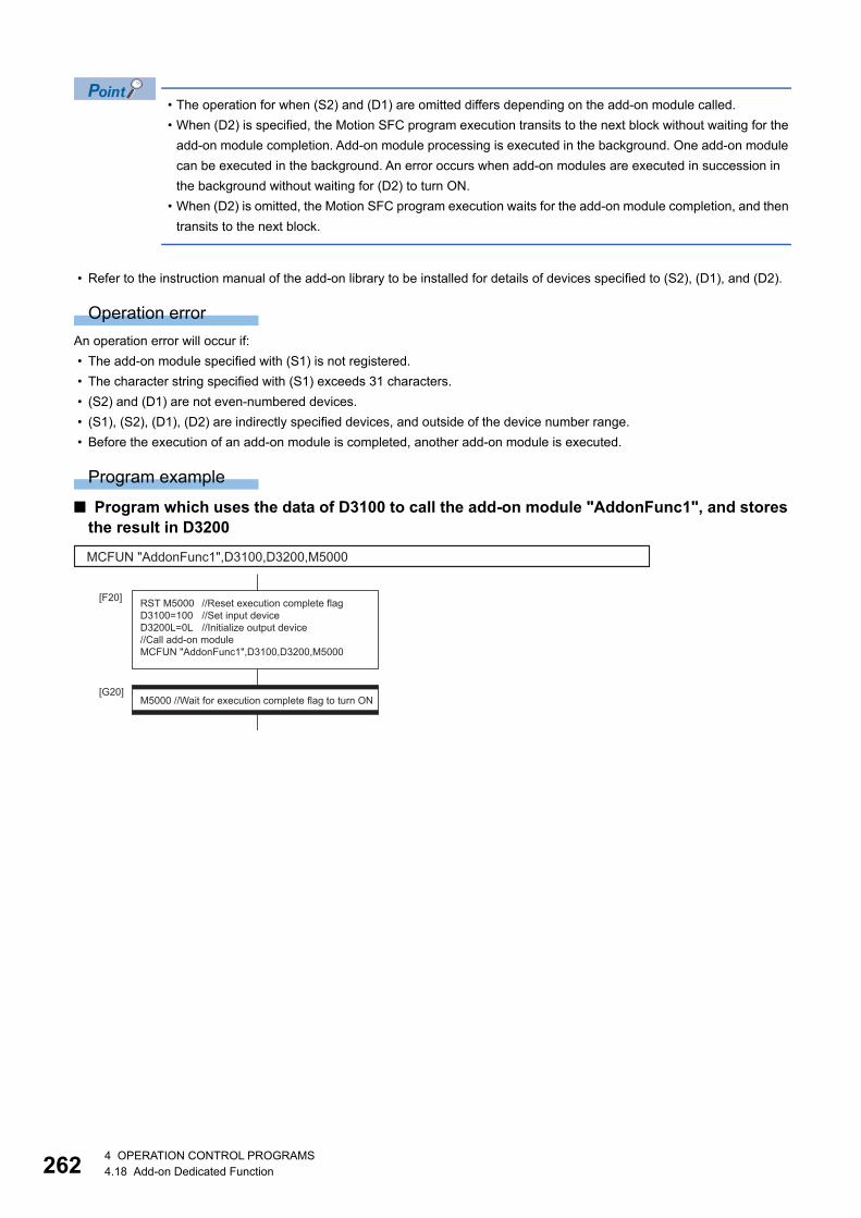
26
• The operation for when (S2) and (D1) are omitted differs depending on the add-on module called.
• When (D2) is specified, the Motion SFC program execution transits to the next block without waiting for the
add-on module completion. Add-on module processing is executed in the background. One add-on module
can be executed in the background. An error occurs when add-on modules are executed in succession in
the background without waiting for (D2) to turn ON.
• When (D2) is omitted, the Motion SFC program execution waits for the add-on module completion, and then
transits to the next block.
• Refer to the instruction manual of the add-on library to be installed for details of devices specified to (S2), (D1), and (D2).
Operation error
An operation error will occur if:
• The add-on module specified with (S1) is not registered.
• The character string specified with (S1) exceeds 31 characters.
• (S2) and (D1) are not even-numbered devices.
• (S1), (S2), (D1), (D2) are indirectly specified devices, and outside of the device number range.
• Before the execution of an add-on module is completed, another add-on module is executed.
Program example
■ Program which uses the data of D3100 to call the add-on module "AddonFunc1", and stores the result in D3200
MCFUN "AddonFunc1",D3100,D3200,M5000
RST M5000 //Reset execution complete flagD3100=100 //Set input deviceD3200L=0L //Initialize output device//Call add-on moduleMCFUN "AddonFunc1",D3100,D3200,M5000
[F20]
[G20]M5000 //Wait for execution complete flag to turn ON
24 OPERATION CONTROL PROGRAMS4.18 Add-on Dedicated Function

4
4.19 Other Instructions
Event task enable: EI
Setting data
There are no setting data.
Processing details
• The execution of an event task is enabled.
• This instruction is usable with a normal task only.
Operation error
An operation error will occur if:
• This instruction is used with other than a normal task.
Program example
■ Enables the execution of an event task.
Format Number of basic steps Usable steps
F/FS G
EI 1
EI
4 OPERATION CONTROL PROGRAMS4.19 Other Instructions 263

26
Event task disable: DI
Setting data
There are no setting data.
Processing details
• The execution of an event task is disabled.
• If an external interrupt or PLC interrupt occurs after execution of the DI instruction, the corresponding event task is
executed once at the execution of the EI instruction. (If two or more external interrupts or PLC interrupts occur during DI,
the corresponding event task is executed only once at the execution of the EI instruction.)
• During DI, a fixed-cycle event task is not executed.
• The execution of an NMI task cannot be disabled.
• The DI status is established at power-on or reset of the Multiple CPU system. EI/DI status does not change by the ON/OFF
of "[Rq.1120] PLC ready flag (R: M30000/Q: M2000)".
Operation error
An operation error will occur if:
• This instruction is used with other than a normal task.
Program example
■ Program which disables the execution of an event task.
Format Number of basic steps Usable steps
F/FS G
DI 1
DI
44 OPERATION CONTROL PROGRAMS4.19 Other Instructions

4
No operation: NOP
Setting data
There are no setting data.
Processing details
This is a no-operation instruction and does not affect the preceding operations.
Operation error
There are no operation errors.
Format Number of basic steps Usable steps
F/FS G
NOP 1
4 OPERATION CONTROL PROGRAMS4.19 Other Instructions 265
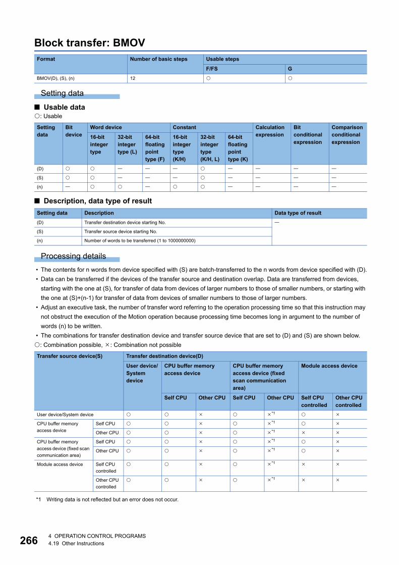
26
Block transfer: BMOV
Setting data
■ Usable data: Usable
■ Description, data type of result
Processing details
• The contents for n words from device specified with (S) are batch-transferred to the n words from device specified with (D).
• Data can be transferred if the devices of the transfer source and destination overlap. Data are transferred from devices,
starting with the one at (S), for transfer of data from devices of larger numbers to those of smaller numbers, or starting with
the one at (S)+(n-1) for transfer of data from devices of smaller numbers to those of larger numbers.
• Adjust an executive task, the number of transfer word referring to the operation processing time so that this instruction may
not obstruct the execution of the Motion operation because processing time becomes long in argument to the number of
words (n) to be written.
• The combinations for transfer destination device and transfer source device that are set to (D) and (S) are shown below.
: Combination possible, : Combination not possible
*1 Writing data is not reflected but an error does not occur.
Format Number of basic steps Usable steps
F/FS G
BMOV(D), (S), (n) 12
Setting data
Bit device
Word device Constant Calculation expression
Bit conditional expression
Comparison conditional expression
16-bit integer type
32-bit integer type (L)
64-bit floating point type (F)
16-bit integer type(K/H)
32-bit integer type(K/H, L)
64-bit floating point type (K)
(D)
(S)
(n)
Setting data Description Data type of result
(D) Transfer destination device starting No.
(S) Transfer source device starting No.
(n) Number of words to be transferred (1 to 1000000000)
Transfer source device(S) Transfer destination device(D)
User device/System device
CPU buffer memory access device
CPU buffer memory access device (fixed scan communication area)
Module access device
Self CPU Other CPU Self CPU Other CPU Self CPU controlled
Other CPU controlled
User device/System device *1
CPU buffer memory
access device
Self CPU *1
Other CPU *1
CPU buffer memory
access device (fixed scan
communication area)
Self CPU *1
Other CPU *1
Module access device Self CPU
controlled
*1
Other CPU
controlled
*1
64 OPERATION CONTROL PROGRAMS4.19 Other Instructions

4
Operation error
An operation error will occur if:
• (S) to (S)+(n-1) is outside the device range.
• (D) to (D)+(n-1) is outside the device range.
• (n) is 0 or a negative number.
• (S) and (D) combination is wrong.
• (S) and (D) are a CPU buffer memory access device other than the self CPU, or a module access device that is not a self
CPU controlled unit.
• (S) is a bit device and the device number is not a multiple of 16
• (D) is a bit device and the device number is not a multiple of 16
Program example
■ Program which batch-transfers a contents for 5 words from D0 to all data for 5 words from #10
■ Program which batch-transfers a contents for 4 words from X0 to all data for 4 words from #20
BMOV #10,D0,K5
12#10#11#12#13#14
Batch transfer34567890
12D0D1D2D3D4
34567890
BMOV #20,X0,K4
#20b0b15
0 0 1 0 0 1 1 1 0 0 0 0 1 1 1 1
#21b0
Batch transfer
b151 0 1 0 0 0 1 1 0 0 0 0 0 1 1 1
#22b0b15
0 0 0 0 0 0 0 0 0 0 0 0 0 1 1 1
#23b0b15
1 1 0 0 0 1 1 1 0 0 0 0 0 0 0 0
X0XF0 0 1 0 0 1 1 1 0 0 0 0 1 1 1 1
X10X1F1 0 1 0 0 0 1 1 0 0 0 0 0 1 1 1
X20X2F0 0 0 0 0 0 0 0 0 0 0 0 0 1 1 1
X30X3F1 1 0 0 0 1 1 1 0 0 0 0 0 0 0 0
4 OPERATION CONTROL PROGRAMS4.19 Other Instructions 267

26
Same data block transfer: FMOV
Setting data
■ Usable data: Usable
■ Description, data type of result
Processing details
• The data specified with (S) or contents of device are transferred a part for (n) words of data to the device specified with (D).
• Adjust an executive task, the number of transfer word referring to the operation processing time so that this instruction may
not obstruct the execution of the motion operation because processing time becomes long in argument to the number of
words (n) to be written.
Operation error
An operation error will occur if:
• (D) to (D)+(n-1) is outside the device range.
• (n) is 0 or a negative number.
• (D) is a CPU buffer memory access device other than the self CPU, or a module access device that is not a self CPU
controlled unit.
• (S) is a bit device and the device number is not a multiple of 16.
• (D) is a bit device and the device number is not a multiple of 16.
Format Number of basic steps Usable steps
F/FS G
FMOV(D), (S), (n) 12
Setting data
Bit device
Word device Constant Calculation expression
Bit conditional expression
Comparison conditional expression
16-bit integer type
32-bit integer type (L)
64-bit floating point type (F)
16-bit integer type(K/H)
32-bit integer type(K/H, L)
64-bit floating point type (K)
(D)
(S)
(n)
Setting data Description Data type of result
(D) Transfer destination device starting No.
(S) Device No. which transfer data or data to be transferred are stored.
(n) Number of words to be transferred (1 to 1000000000)
84 OPERATION CONTROL PROGRAMS4.19 Other Instructions

4
Program example
■ Program which sets 3456H to all data for 100 words from #10
■ Program which sets a content of D4000 to all data for 50 words from W0
■ Program which sets 8000H to all data for 4 words from M0
FMOV #10,H3456,K100
H3456H3456H3456
�
H3456
#10#11#12�
#109
TransferH3456
FMOV W0,D4000,K50
123412341234�
1234
W0W1W2�
W31
TransferD4000 1234
FMOV M0,H8000,K4
M0M15
M16
Transfer
M31
M32M47
M48M631 0 0 0 0 0 0 0 0 0 0 0 0 0 0 0
1 0 0 0 0 0 0 0 0 0 0 0 0 0 0 0
1 0 0 0 0 0 0 0 0 0 0 0 0 0 0 0
1 0 0 0 0 0 0 0 0 0 0 0 0 0 0 0
1 0 0 0 0 0 0 0 0 0 0 0 0 0 0 0
b0b15
4 OPERATION CONTROL PROGRAMS4.19 Other Instructions 269

27
Write device data to buffer memory: TO
Setting data
■ Usable data: Usable
■ Description, data type of result
Processing details
• (n) words of data from the device specified with (S) are written to the address specified with (D2) and after of the buffer
memory in the specified with (D1).
Writing device data can be performed with the module access device (U\G).
(Example)
Writing 2 words from #0 to buffer memory address 0H of intelligent function module (start I/O number: 010H).
Refer to the following for details of module access device.
MELSEC iQ-R Motion Controller Programming Manual (Common)
Format Number of basic steps Usable steps
F/FS G
TO(D1), (D2), (S), (n) 14
Setting data
Bit device
Word device Constant Calculation expression
Bit conditional expression
Comparison conditional expression
16-bit integer type
32-bit integer type (L)
64-bit floating point type (F)
16-bit integer type(K/H)
32-bit integer type(K/H, L)
64-bit floating point type (K)
(D1)
(D2)
(S)
(n)
Setting data Description Data type of result
(D1) First I/O No. of the module (000H to FF0H, 3E00H to 3E30H)
(D2) First address of the buffer memory which writes data. (0 to end of target module buffer
memory)
(S) Start device No. which writing data are stored.
(n) Number of words to be written (1 to within range of target module buffer memory)
H0000H0005H000A
�
H0000
(D2)Write the data of apart for (n) words
(D1) Intelligent functionmodule buffer memory
H0000H0005H000A
�
H0000
Device memory
(S)
U1\G0L = #0L
04 OPERATION CONTROL PROGRAMS4.19 Other Instructions

4
• First I/O No. of the module set by [System Parameter] [I/O Assignment Setting] in GX Works3 is specified by (D1). (D1)
sets 20H by the system configuration when a TO instruction is executed in the D/A conversion module (R64DA).
• The upper limit for the value that can be set for number of words (n) to be written and buffer memory start address (D2)
differs depending on the target module. Refer to the manual of module used for details.
• Adjust an executive task, the number of words (n) to be written referring to the operation processing time so that this
instruction may not obstruct the execution of the motion operation because processing time becomes long in argument to
the number of words (n) to be written.
• Refer to the following for intelligent function modules that can be used as the Motion CPU control module.
MELSEC iQ-R Motion controller Programming Manual (Common)
• The combinations for write destination and write source that are set to (S) and (D1) are shown below.
: Combination possible, : Combination not possible
Operation error
An operation error will occur if:
• Number of words (n) to be written is outside the range.
• Motion CPU cannot communicate with target module at the instruction execution.
• Abnormalities of the target module were detected at the instruction execution.
• The address specified with (D2) is outside the buffer memory range.
• Start device No. (S) which writing data are stored + number of words (n) to be written is outside the device range.
• (S) is a bit device and the device number is not a multiple of 16.
• (S) and (D1) combination is wrong.
Program example
■ 2 words from #0 are written to buffer memory address 0H of the intelligent function module (First I/O No.: 010H)
Write source (S) Write destination (D1)
CPU start I/O number (3E00H to 3E30H) Module start I/O number (000H to FF0H)
Self CPU Other CPU Self CPU controlled Other CPU controlled
User device/System device
CPU buffer memory access
device
Self CPU
Other CPU
CPU buffer memory access
device (fixed scan
communication area)
Self CPU
Other CPU
Module access device Self CPU
controlled
Other CPU
controlled
Powersupplymodule
R04CPU
First I/O No.No.: 3E00H
R32MTCPU
First I/O No.No.: 3E10H
RX40C7
First I/O No.No.: 00H
R64AD
First I/O No.No.: 10H
R64DA
First I/O No.No.: 20H
TO H010,H0,#0,K2
1000H1H
2 words transfer
200100
Device memoryBuffer memory
Intelligent function module(First I/O No.: 010H)
#0#1 200
4 OPERATION CONTROL PROGRAMS4.19 Other Instructions 271

27
Read device data from buffer memory: FROM
Setting data
■ Usable data: Usable
■ Description, data type of result
Processing details
• (n) words of data are read from the address specified with (S2) of the buffer memory in the module specified with (S1), and
are stored since the device specified with (S2).
Writing device data can be performed with the module access device (U\G).
(Example)
Reading 1 word of data from buffer memory address 10H of intelligent function module (start I/O number:
020H), and storing in W0.
Refer to the following for details of module access device.
MELSEC iQ-R Motion Controller Programming Manual (Common)
Format Number of basic steps Usable steps
F/FS G
FROM(D), (S1), (S2), (n) 14
Setting data
Bit device
Word device Constant Calculation expression
Bit conditional expression
Comparison conditional expression
16-bit integer type
32-bit integer type (L)
64-bit floating point type (F)
16-bit integer type(K/H)
32-bit integer type(K/H, L)
64-bit floating point type (K)
(D)
(S1)
(S2)
(n)
Setting data Description Data type of result
(D) Start device No. which stores the reading data.
(S1) First I/O No. of the module (000H to FF0H, 3E00H to 3E30H)
(S2) First address of the buffer memory which it will be read. (0 to end of target module buffer
memory)
(n) Number of words to be read (1 to within range of target module buffer memory)
H0000H0005H000A
�
H0000
(D)Read the data of a
part for (n) word
H0000H0005H000A
�
H0000
Device memory
(S2)
Intelligent functionmodule buffer memory
(S1)
W0 = U2\G16
24 OPERATION CONTROL PROGRAMS4.19 Other Instructions

4
• First I/O No. of the module set by [System Parameter] [I/O Assignment Setting] in GX Works3 is specified by (S1). (S1)
sets 10H by the system configuration when a FROM instruction is executed in the A/D conversion module (R64AD).
• The upper limit for the value that can be set for number of words (n) to be read, and buffer memory start address (D2)
differs depending on the target module. Refer to the manual of module used for details.
• Adjust an executive task, the number of words (n) to be read referring to the operation processing time so that this
instruction may not obstruct the execution of the motion operation because processing time becomes long in argument to
the number of words (n) to be read.
• Refer to the following for intelligent function modules that can be used as the Motion CPU control module.
MELSEC iQ-R Motion controller Programming Manual (Common)
• The combinations for read destination and read source that are set to (S1) and (D) are shown below.
: Combination possible, : Combination not possible
*1 Reading data is not reflected but an error does not occur.
Operation error
An operation error will occur if:
• Number of words (n) to be read is outside the range.
• Motion CPU cannot communicate with target module at the instruction execution.
• Abnormalities of the target module were detected at the instruction execution.
• The address specified with (S2) is outside the buffer memory range.
• Start device No. (D) which stores the reading data + number of words (n) to be read is outside the device range.
• (D) is a bit device and the device number is not a multiple of 16.
• (S1) and (D) combination is wrong.
Program example
■ 1 word is read from the buffer memory address 10H of the intelligent function module (First I/O No.: 020H), and is stored in W0
Read source(S1) Read destination(D)
User device/System device
CPU buffer memory access device
CPU buffer memory access device (fixed scan communication area)
Module access device
Self CPU Other CPU Self CPU Other CPU Self CPU controlled
Other CPU controlled
User device/System device *1
CPU start I/O number
(3E00H to 3E30H)
Self CPU *1
Other CPU *1
Module start I/O
number (000H to FF0H)
Self CPU
controlled
*1
Other CPU
controlled
*1
Powersupplymodule
R04CPU
First I/O No.No.: 3E00H
R32MTCPU
First I/O No.No.: 3E10H
RX40C7
First I/O No.No.: 00H
R64AD
First I/O No.No.: 10H
R64DA
First I/O No.No.: 20H
FROM W0,H020,H10,K1
1 word transfer 10010H11H 200
300
Buffer memory
Intelligent function module(First I/O No.: 020H)
100Device memory
W0
4 OPERATION CONTROL PROGRAMS4.19 Other Instructions 273

27
Write buffer memory data to head module: RTO
Setting data
■ Usable data: Usable
■ Description, data type of result
Processing details
• (n) words of data from the device specified with (S) are written to the address specified with (D3) and after of the buffer
memory in the intelligent function module specified with (D2). The intelligent function module is mounted to the target
SSCNET/H head module specified with (D1). After writing completion of the device data, the complete bit device
specified with (D4) turns ON.
Format Number of basic steps Usable steps
F/FS G
RTO(D1), (D2), (D3), (S), (n), (D4) 21
Setting data
Bit device
Word device Constant Calculation expression
Bit conditional expression
Comparison conditional expression
16-bit integer type
32-bit integer type (L)
64-bit floating point type (F)
16-bit integer type(K/H)
32-bit integer type(K/H, L)
64-bit floating point type (K)
(D1)
(D2)
(D3)
(S)
(n)
(D4)
Setting data Description Data type of result
(D1) RIO Axis No. of the target SSCNET/H head module (601 to 608)
(D2) First I/O No. of the intelligent function module which writes data.
(00 to FEH: First 2 digits when the I/O No. is expressed with 3 digits)
(D3) First address of the buffer memory of the intelligent function module which writes data.
(S) Start device No. which writing data are stored.
(n) Number of words to be written (1 to 32767)
(D4) Complete devices
(D4+0): Self CPU device is made to turn ON by the writing completion.
(D4+1): Self CPU device is made to turn ON by the writing abnormal completion. ("D4+0"
also turns ON at the abnormal completion)
H0000H0005H000A
�
H0000
(D3)
(D1)
Write the data of apart for (n) words
(D2) Intelligent functionmodule buffer memory
SSCNET�/H head module
H0000H0005H000A
�
H0000
Device memory
(S)
44 OPERATION CONTROL PROGRAMS4.19 Other Instructions

4
• First I/O No. of the module mounted to the SSCNET/H head module set by [Motion CPU Common Parameter] [Head
Module] is specified by (D2). (D2) sets 05H by the system configuration when a RTO instruction is executed in the D/A
conversion module (L60DA4).
• Adjust an executive task, the number of words (n) to be written referring to the operation processing time so that this
instruction may not obstruct the execution of the motion operation because processing time becomes long in argument to
the number of words (n) to be written.
• The following modules can be used.
• Do resetting of the complete bit device by the user program.
• Another RTO instruction cannot be processed until RTO instruction is executed and a complete bit device is turned ON.
When RTO instruction is executed again, before RTO instruction is executed and complete bit device is turned ON, the
RTO instruction executed later becomes an error.
• To write 3 words or more of data to the SSCNET/H head module, 2 words of writing data are written each time and then
repeated. This means that data specified with 3 words or more is not written at the same timing. For data that needs to be
written at the same timing use the refresh of the cyclic transmission of the SSCNET/H head module word device (Buffer
memory of SSCNET/H head module and intelligent function module). Refer to the following for details.
MELSEC-L SSCNETIII/H Head Module User's Manual
Operation error
An operation error will occur if:
• Number of words (n) to be written is outside the range.
• The target SSCNET/H head module RIO axis No. specified with (D1) is outside the range of 601 to 608.
• The target SSCNET/H head module is not connected at instruction execution.
• Start device No. (S) which writing data are stored + number of words (n) to be written is outside the device range.
• (S) is a bit device and the device number is not a multiple of 16.
• RTO instruction was executed again before the RTO instruction is executed and complete bit device is turned ON.
• RTO instruction was executed for the RIO axis of the sensing module.
Abnormal completion (D4+1) of complete device turns ON if:
• Abnormalities of the target SSCNET/H head module were detected at the instruction execution.
• First I/O No. of the intelligent function module specified with (D2) differ from the intelligent function module.
• The first address of the buffer memory of the intelligent function module specified with (D3) is outside the buffer memory
range.
Module Model
Analogue input L60AD4, L60AD4-2GH
Analogue output L60DA4
High-speed counter LD62, LD62D
Powersupplymodule
R04CPU R32MTCPU
First I/O No.No.: 30H
First I/O No.No.: 40H
First I/O No.No.: 50H
Powersupplymodule
SSCNET�/Hhead module
LX40C6 L60AD4 L60DA4MR-J4(W)-�B MR-J4(W)-�B
4 OPERATION CONTROL PROGRAMS4.19 Other Instructions 275

27
Program example
■ 2 words from #0 are written to buffer memory address 0H of the intelligent function module (First I/O No.: 010H) on the RIO axis 603 of the SSCNET/H head module
RTO K603,H01,H0,#0,K2,M10
1000H1H
2 words transfer
200100
Device memoryBuffer memory
Intelligent function module(First I/O No.: 010H)
SSCNET�/H head module (RIO Axis No.603)
#0#1 200
RST M10RTO K603,H01,H0,#0,K2,M10
[F10]
[G10]M10
64 OPERATION CONTROL PROGRAMS4.19 Other Instructions

4
Read buffer memory data from head module: RFROM
Setting data
■ Usable data: Usable
■ Description, data type of result
Processing details
• (n) words of data are read from the address specified with (S3) of the buffer memory in the intelligent function module
specified with (S2). The intelligent function module is mounted to the target SSCNET/H head module specified with (S1).
The data is written to device specified with (D) and after.
Format Number of basic steps Usable steps
F/FS G
RFROM(D), (S1), (S2), (S3), (n), (D1) 21
Setting data
Bit device
Word device Constant Calculation expression
Bit conditional expression
Comparison conditional expression
16-bit integer type
32-bit integer type (L)
64-bit floating point type (F)
16-bit integer type(K/H)
32-bit integer type(K/H, L)
64-bit floating point type (K)
(D)
(S1)
(S2)
(S3)
(n)
(D1)
Setting data Description Data type of result
(D) Start device No. which stores the reading data.
(S1) RIO Axis No. of the target SSCNET/H head module (601 to 608)
(S2) First I/O No. of the intelligent function module which data to be read are stored.
(00 to FEH: First 2 digits when the I/O No. is expressed with 3 digits)
(S3) First address of the buffer memory of the intelligent function module which stores the data
to be read.
(n) Number of words to be read (1 to 32767)
(D1) Complete devices
(D1+0): Self CPU device is made to turn ON by the reading completion.
(D1+1): Self CPU device is made to turn ON by the reading abnormal completion. ("D1+0"
also turns ON at the abnormal completion)
H0000H0005H000A
:H0000
(D)Read the data of apart for (n) words
H0000H0005H000A
:H0000
Device memory
(S3)
Intelligent functionmodule buffer memory
(S2)(S1)
SSCNET�/H head module
4 OPERATION CONTROL PROGRAMS4.19 Other Instructions 277
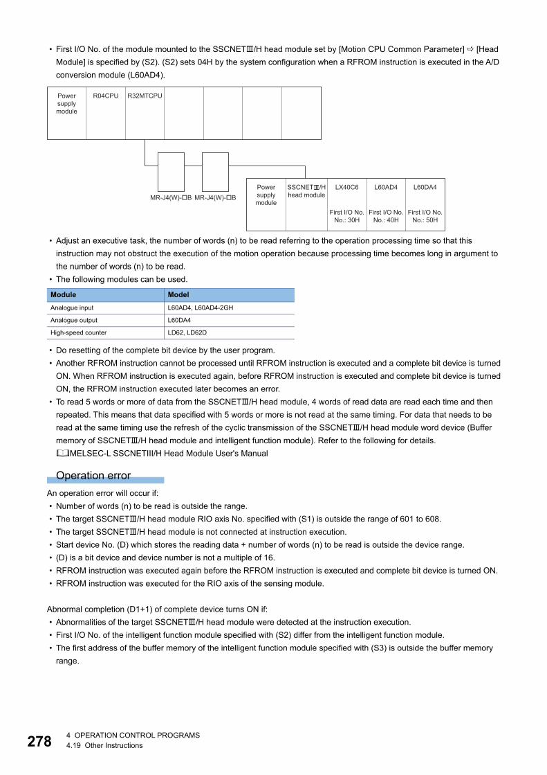
27
• First I/O No. of the module mounted to the SSCNET/H head module set by [Motion CPU Common Parameter] [Head
Module] is specified by (S2). (S2) sets 04H by the system configuration when a RFROM instruction is executed in the A/D
conversion module (L60AD4).
• Adjust an executive task, the number of words (n) to be read referring to the operation processing time so that this
instruction may not obstruct the execution of the motion operation because processing time becomes long in argument to
the number of words (n) to be read.
• The following modules can be used.
• Do resetting of the complete bit device by the user program.
• Another RFROM instruction cannot be processed until RFROM instruction is executed and a complete bit device is turned
ON. When RFROM instruction is executed again, before RFROM instruction is executed and complete bit device is turned
ON, the RFROM instruction executed later becomes an error.
• To read 5 words or more of data from the SSCNET/H head module, 4 words of read data are read each time and then
repeated. This means that data specified with 5 words or more is not read at the same timing. For data that needs to be
read at the same timing use the refresh of the cyclic transmission of the SSCNET/H head module word device (Buffer
memory of SSCNET/H head module and intelligent function module). Refer to the following for details.
MELSEC-L SSCNETIII/H Head Module User's Manual
Operation error
An operation error will occur if:
• Number of words (n) to be read is outside the range.
• The target SSCNET/H head module RIO axis No. specified with (S1) is outside the range of 601 to 608.
• The target SSCNET/H head module is not connected at instruction execution.
• Start device No. (D) which stores the reading data + number of words (n) to be read is outside the device range.
• (D) is a bit device and device number is not a multiple of 16.
• RFROM instruction was executed again before the RFROM instruction is executed and complete bit device is turned ON.
• RFROM instruction was executed for the RIO axis of the sensing module.
Abnormal completion (D1+1) of complete device turns ON if:
• Abnormalities of the target SSCNET/H head module were detected at the instruction execution.
• First I/O No. of the intelligent function module specified with (S2) differ from the intelligent function module.
• The first address of the buffer memory of the intelligent function module specified with (S3) is outside the buffer memory
range.
Module Model
Analogue input L60AD4, L60AD4-2GH
Analogue output L60DA4
High-speed counter LD62, LD62D
Powersupplymodule
R04CPU R32MTCPU
First I/O No.No.: 30H
First I/O No.No.: 40H
First I/O No.No.: 50H
Powersupplymodule
SSCNET�/Hhead module
LX40C6 L60AD4 L60DA4MR-J4(W)-�B MR-J4(W)-�B
84 OPERATION CONTROL PROGRAMS4.19 Other Instructions

4
Program example
■ 1 word is read from the buffer memory address 10H of the intelligent function module (First I/O No.: 020H) on the RIO axis 602 of the SSCNET/H head module, and is stored in W0
RFROM W0,K602,H02,H10,K1,M0
1 word transfer 10010H11H 200
300
Buffer memory
Intelligent function module(First I/O No.: 020H)
100Device memory
W0
SSCNET�/H head module (RIO Axis No.602)
RST M0RFROM W0,K602,H02,H10,K1,M0
[F20]
[G20]M0
4 OPERATION CONTROL PROGRAMS4.19 Other Instructions 279

28
Time to wait: TIME
Setting data
■ Usable data: Usable
■ Description, data type of result
Processing details
• A wait state continues for the time specified with (S). The result is false when the elapsed time is less than the preset time,
or the result is true and execution transits when the preset time has elapsed.
• When a 16-bit integer type word device is used to specify any of 32768 to 65535[ms] at (S), convert it into an unsigned 32-
bit integer value with ULONG. (Refer to the program example.)
Operation error
An operation error will occur if:
• (S) is an indirectly specified device and its device No. is outside the range.
• The data (device data at indirect specification) specified with (S) is outside the range of 0 to 2147483647.
Program example
■ Program which sets a wait of 60 seconds (when constant is specified)
■ Program for a case where there may be a wait of 32768 to 65535 [ms] for 16-bit integer type indirect designation (#0)
■ Program which SETS (RSTs) a bit device when the specified time has elapsed
Format Number of basic steps Usable steps
F/FS G
TIME(S) 8
Setting data
Bit device
Word device Constant Calculation expression
Bit conditional expression
Comparison conditional expression
16-bit integer type
32-bit integer type (L)
64-bit floating point type (F)
16-bit integer type(K/H)
32-bit integer type(K/H, L)
64-bit floating point type (K)
(S)
Setting data Description Data type of result
(S) Waiting time (0 to 2147483647)[ms] Logical type (true/false)
TIME K60000
TIME ULONG(#0)
SET M100 = TIME K60000
04 OPERATION CONTROL PROGRAMS4.19 Other Instructions

4
• When the waiting time setting is indirectly specified with a word device, the value imported first is used as
the device value for exercising control. The set time cannot be changed if the device value is changed
during a wait state.
• The TIME instruction is equivalent to a conditional expression, and therefore may be set on only the last line
of a transition (G) program.
• When the transition program (Gn) of the same number having the TIME instruction setting is used in
multiple Motion SFC programs, avoid running them at the same time. (If they are run simultaneously, the
waiting time in the program run first will be illegal.)
• Another transition program (Gn) can executed a time of instruction by multiple Motion SFC program
simultaneously. (Multi active step up to 1024 (for operating system software version "08" or earlier, up to
256).)
• While time by TIME instruction waits, the wait time can not be stopped.
4 OPERATION CONTROL PROGRAMS4.19 Other Instructions 281
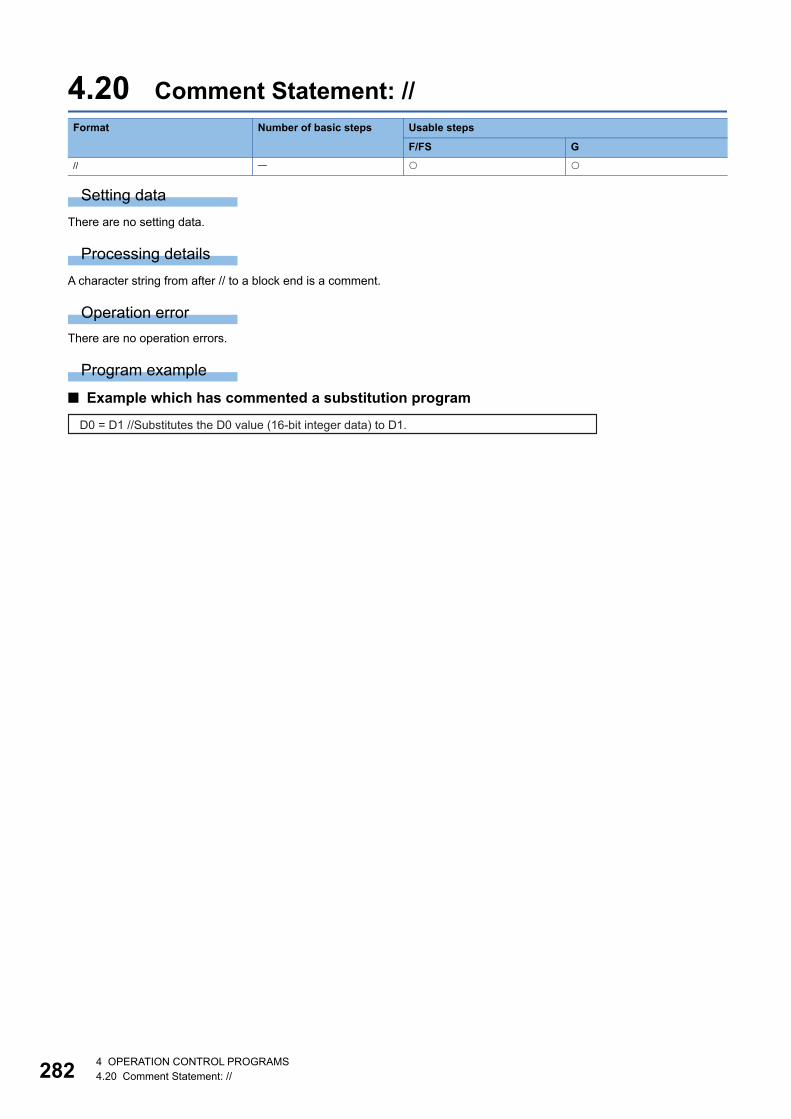
28
4.20 Comment Statement: //
Setting data
There are no setting data.
Processing details
A character string from after // to a block end is a comment.
Operation error
There are no operation errors.
Program example
■ Example which has commented a substitution program
Format Number of basic steps Usable steps
F/FS G
//
D0 = D1 //Substitutes the D0 value (16-bit integer data) to D1.
24 OPERATION CONTROL PROGRAMS4.20 Comment Statement: //

5
5 TRANSITION PROGRAMS
5.1 Transition Programs
Transition programs • Substitution operation expressions, motion-dedicated functions, bit device control commands and transition conditions can
be set in transition programs.
• Multiple blocks can be set in one transition program.
• There are no restrictions on the number of blocks that may be set in a single transition program. Note that one program is
within 128k bytes.
• The maximum number of characters in one block is 1020.
• Transition condition must be set in the last block of a transition program. Transition program is repeated until the transition
condition enables, and when the transition condition has enabled, it shifts to the next step. Transition condition can be set
only in the last block.
• As a special transition program, a program which only no operation (NOP) is set in one block can be created. This program
is used when it is not set as interlock to process to next step with completion of servo program. (Page 112 To proceed
to the next step on operation completion)
A transition program example is shown below.
What can be set as a transition condition in the last block are bit conditional expressions, comparison conditional expressions
and device set (SET=)/device reset (RST=) which return logical data values (true/false). In the case of device set (SET=)/
device reset (RST=), whether the bit or comparison conditional expression specified at (S) is true or false is a transition
condition, and when the transition condition enables, device set/reset is executed and execution shifts to the next step.
Transition condition description examples are given below.
• A transition program differs from an operation control program in that a transition condition is set in the last
block. Other settings are the same as those of the operation control program.
• When setting device set (SET=)/device reset (RST=) in the last block as a transition condition, the bit or
comparison conditional expression specified with (S) is not omissible.
• Only the bit or comparison conditional expression cannot be set in other than the last block. Device set
(SET=)/device reset (RST=) can be set in other than the last block.
Classification Description example
Bit conditional expression M0
!M0+X10*M100
Comparison conditional expression (D0>K100)+(D100L!=K20L)
Device set (SET=) SET Y0=M100
Device reset (RST=) RST M10=D0==K100
1 program
Transition condition
#0=D0+(D1+D2)*#5//Substitution expression (four arithmetic operations)W0:F=SIN(#10F)//Substitution expression (standard function)CHGV(K2,K10)//Motion-dedicated functionSET M100=M0+X0//Bit device control (SET=)RST M10=D100>K10//Bit device control (RST=)DIN D0,X0//Bit device control (DIN)D0>K100//Standby until transition condition enables
1 block
Comment
5 TRANSITION PROGRAMS5.1 Transition Programs 283

28
MEMO
45 TRANSITION PROGRAMS5.1 Transition Programs

6
6 OPERATION FOR MOTION SFC AND PARAMETER
6.1 Task DefinitionsWhen to execute the Motion SFC program processing can be set only once in the program parameter per program. Roughly
classified, there are the following three different tasks.
• Fixed cycle event task operates regardless of the operation cycle setting.
(Example)
When operation cycle is set to 0.888ms, a 0.222ms fixed cycle event task is executed.
• Set the interrupt pointer (I0 to I15) in the module detailed settings of the Motion CPU controlled input
module displayed by the "Detailed" button in [R Series Common Parameter] [Module Configuration List]
"Setting Item".
6.2 Number of Consecutive Transitions and Task Operation
Number of consecutive transitionsWith "execution of active step judgment of next transition condition transition processing performed when condition
enables (transition of active step)" defined as a single basic operation of the Motion SFC program execution control in the
execution cycle of the corresponding task, this operation is performed for the number of active steps to terminate processing
once. And the same operation is processed continuously in the next cycle. In this case, the transition destination step is
executed in the next cycle when the transition condition enables.
Consecutive transition control indicates that transition destination steps are executed one after another in the same one
execution cycle when their transition conditions have enabled (single basic operation is performed consecutively). In this
case, set the number of consecutive transitions. Control exercised is common to the Motion SFC programs executed by
normal tasks.
Set the number of consecutive transitions to the Motion SFC programs executed by event and NMI tasks for
every program.
Task type Contents
Normal task Executes in Motion CPU main cycle (free time).
Event task • Executes in fixed cycle (0.222ms, 0.444ms, 0.888ms, 1.777ms, 3.555ms, 7.111ms, 14.222ms).
• Executes when the input set to the event task factor among external interrupts (16 points of interrupt pointer (I0 to
I15)) turns on.
• Executes by an interrupt from the PLC CPU.
NMI task Executes when the input set to the NMI task factor among external interrupts (16 points of interrupt pointer (I0 to I15))
turns on.
6 OPERATION FOR MOTION SFC AND PARAMETER6.1 Task Definitions 285

28
Task operation
Normal task operation
■ OperationsThe Motion SFC program is executed in the main cycle (free time) of the Motion CPU. The processing outline is shown below.
• Number of consecutive transitions is set to "2".
■ Points • The Motion SFC program which includes motion control steps should be set to a normal task.
• During execution of an event or NMI task, the execution of the normal task is suspended. Note that since the normal task
allows the event task disable instruction (DI) to be described in an operation control step, the event task can be disabled in
the area enclosed by the event task disable instruction (DI) and event task enable instruction (EI). The event task enable/
disable status can be confirmed with "EI flag (SM752)".
Event task operation
■ OperationsAn event task executes the Motion SFC program at occurrence of an event. There are the following events.
Event Contents
Fixed cycle The Motion SFC program is executed periodically in any of 0.222ms, 0.444ms, 0.888ms, 1.777ms, 3.555ms,
7.111ms and 14.222ms cycles.
External interrupt (16 points interrupt pointer
(I0 to I15))
Among 16 points of the interrupt pointer (I0 to I15) assigned to the Motion CPU controlled input module, the
Motion SFC program is run when the input set for an event task turns on.
PLC interrupt The Motion SFC program is executed when the M(P).GINT/D(P).GINT instruction is executed in the sequence
program.
Normal task is ended with END. (No continuation operation)When making it operate continuously, it returns to starting step in a jump.
F20
Program 1
F1
F2
F3
END
Program name
(1)
(2)
(A)
(B)
(C)
F30
Program 2
F5
F6
F7
F8
END
Program name
Sequence programSFCS1 SFCS2
Normal task (1)
(C)
(A)
Main cycle Main cycle
(2) (B)
Main cycle
66 OPERATION FOR MOTION SFC AND PARAMETER6.2 Number of Consecutive Transitions and Task Operation
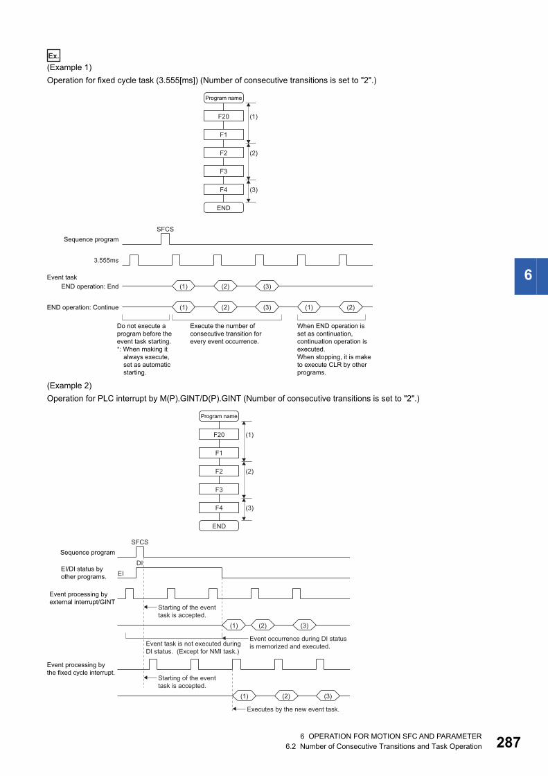
6
Ex.
(Example 1)
Operation for fixed cycle task (3.555[ms]) (Number of consecutive transitions is set to "2".)
(Example 2)
Operation for PLC interrupt by M(P).GINT/D(P).GINT (Number of consecutive transitions is set to "2".)
Do not execute aprogram before theevent task starting.*: When making it
always execute, set as automatic starting.
When END operation isset as continuation,continuation operation isexecuted.When stopping, it is maketo execute CLR by otherprograms.
F20
F1
F2
F3
F4
END
Program name
(1)
(3)
(2)
Sequence programSFCS
3.555ms
END operation: EndEvent task
(1) (2) (3)
(1) (2) (1) (2)(3)END operation: Continue
Execute the number ofconsecutive transition for every event occurrence.
F20
F1
F2
F3
F4
END
Program name
(1)
(3)
(2)
Sequence programSFCS
DIEI
EI/DI status byother programs.
Event processing byexternal interrupt/GINT
(1) (2) (3)
Starting of the eventtask is accepted.
Event occurrence during DI status is memorized and executed.
Event processing bythe fixed cycle interrupt.
(1) (2) (3)
Starting of the eventtask is accepted.
Event task is not executed duringDI status. (Except for NMI task.)
Executes by the new event task.
6 OPERATION FOR MOTION SFC AND PARAMETER6.2 Number of Consecutive Transitions and Task Operation 287
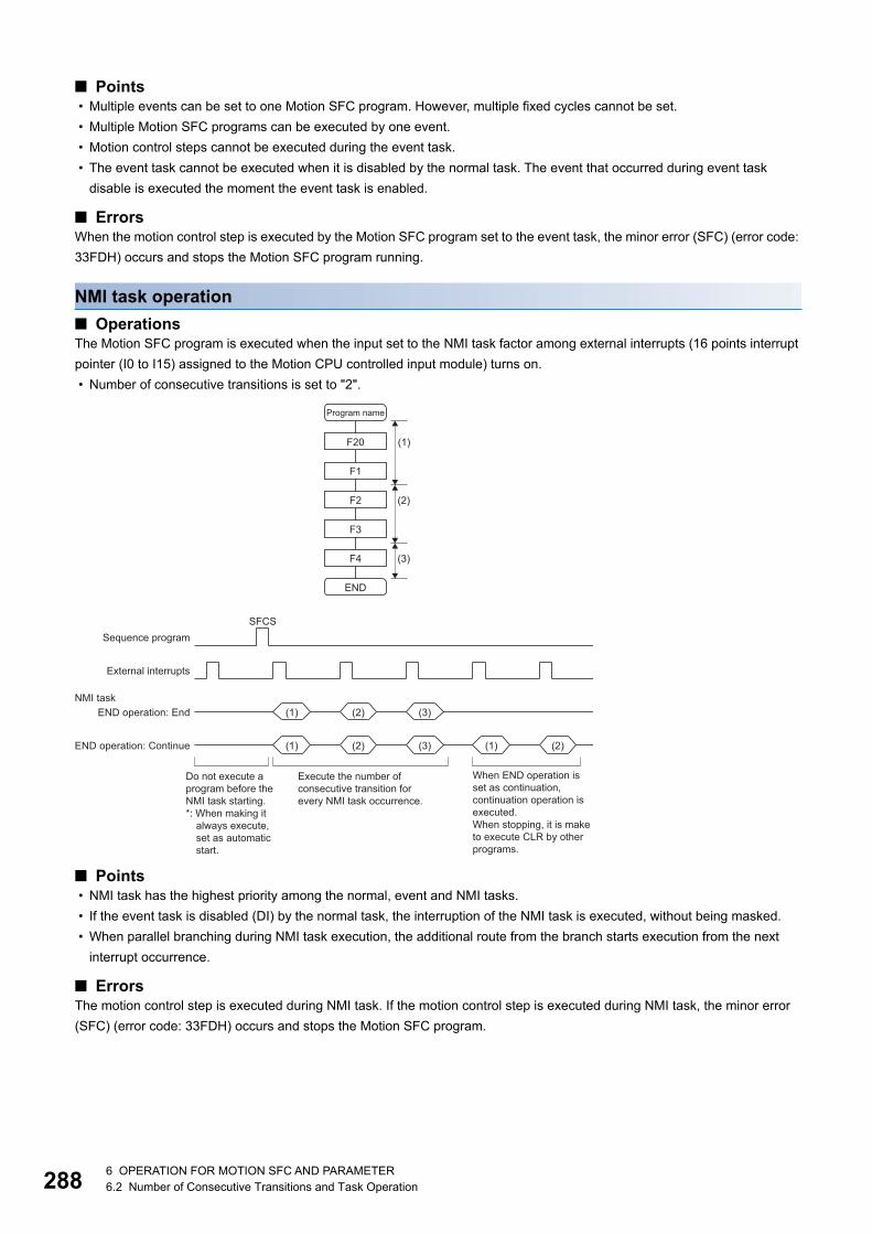
28
■ Points • Multiple events can be set to one Motion SFC program. However, multiple fixed cycles cannot be set.
• Multiple Motion SFC programs can be executed by one event.
• Motion control steps cannot be executed during the event task.
• The event task cannot be executed when it is disabled by the normal task. The event that occurred during event task
disable is executed the moment the event task is enabled.
■ ErrorsWhen the motion control step is executed by the Motion SFC program set to the event task, the minor error (SFC) (error code:
33FDH) occurs and stops the Motion SFC program running.
NMI task operation
■ OperationsThe Motion SFC program is executed when the input set to the NMI task factor among external interrupts (16 points interrupt
pointer (I0 to I15) assigned to the Motion CPU controlled input module) turns on.
• Number of consecutive transitions is set to "2".
■ Points • NMI task has the highest priority among the normal, event and NMI tasks.
• If the event task is disabled (DI) by the normal task, the interruption of the NMI task is executed, without being masked.
• When parallel branching during NMI task execution, the additional route from the branch starts execution from the next
interrupt occurrence.
■ ErrorsThe motion control step is executed during NMI task. If the motion control step is executed during NMI task, the minor error
(SFC) (error code: 33FDH) occurs and stops the Motion SFC program.
Do not execute a program before the NMI task starting. *: When making it
always execute,set as automaticstart.
When END operation isset as continuation,continuation operation isexecuted.When stopping, it is maketo execute CLR by otherprograms.
F20
F1
F2
F3
F4
END
Program name
(1)
(3)
(2)
Sequence programSFCS
External interrupts
END operation: EndNMI task
END operation: Continue
Execute the number of consecutive transition for every NMI task occurrence.
(1) (2) (3)
(1) (2) (1) (2)(3)
86 OPERATION FOR MOTION SFC AND PARAMETER6.2 Number of Consecutive Transitions and Task Operation
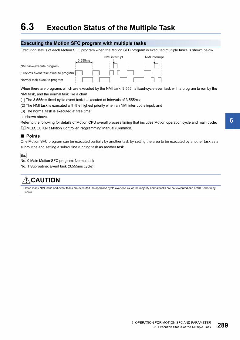
6
6.3 Execution Status of the Multiple Task
Executing the Motion SFC program with multiple tasksExecution status of each Motion SFC program when the Motion SFC program is executed multiple tasks is shown below.
When there are programs which are executed by the NMI task, 3.555ms fixed-cycle even task with a program to run by the
NMI task, and the normal task like a chart,
(1) The 3.555ms fixed-cycle event task is executed at intervals of 3.555ms;
(2) The NMI task is executed with the highest priority when an NMI interrupt is input; and
(3) The normal task is executed at free time.
as shown above.
Refer to the following for details of Motion CPU overall process timing that includes Motion operation cycle and main cycle.
MELSEC iQ-R Motion Controller Programming Manual (Common)
■ PointsOne Motion SFC program can be executed partially by another task by setting the area to be executed by another task as a
subroutine and setting a subroutine running task as another task.
Ex.
No. 0 Main Motion SFC program: Normal task
No. 1 Subroutine: Event task (3.555ms cycle)
CAUTION• If too many NMI tasks and event tasks are executed, an operation cycle over occurs, or the majority normal tasks are not executed and a WDT error may
occur.
3.555ms event task-execute program
NMI task-execute program
Normal task-execute program
3.555msNMI interrupt NMI interrupt
6 OPERATION FOR MOTION SFC AND PARAMETER6.3 Execution Status of the Multiple Task 289
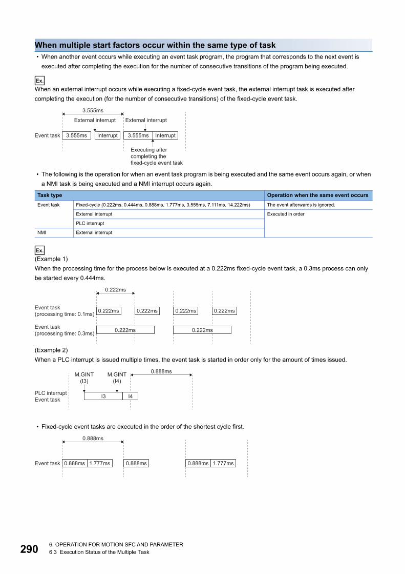
29
When multiple start factors occur within the same type of task • When another event occurs while executing an event task program, the program that corresponds to the next event is
executed after completing the execution for the number of consecutive transitions of the program being executed.
Ex.
When an external interrupt occurs while executing a fixed-cycle event task, the external interrupt task is executed after
completing the execution (for the number of consecutive transitions) of the fixed-cycle event task.
• The following is the operation for when an event task program is being executed and the same event occurs again, or when
a NMI task is being executed and a NMI interrupt occurs again.
Ex.
(Example 1)
When the processing time for the process below is executed at a 0.222ms fixed-cycle event task, a 0.3ms process can only
be started every 0.444ms.
(Example 2)
When a PLC interrupt is issued multiple times, the event task is started in order only for the amount of times issued.
• Fixed-cycle event tasks are executed in the order of the shortest cycle first.
Task type Operation when the same event occurs
Event task Fixed-cycle (0.222ms, 0.444ms, 0.888ms, 1.777ms, 3.555ms, 7.111ms, 14.222ms) The event afterwards is ignored.
External interrupt Executed in order
PLC interrupt
NMI External interrupt
Event task 3.555ms 3.555msInterrupt Interrupt
3.555ms
External interrupt External interrupt
Executing aftercompleting the fixed-cycle event task
Event task(processing time: 0.1ms) 0.222ms 0.222ms 0.222ms 0.222ms
Event task(processing time: 0.3ms) 0.222ms 0.222ms
0.222ms
PLC interruptEvent task I3 I4
0.888msM.GINT(I3)
M.GINT(I4)
Event task 0.888ms 1.777ms 0.888ms 1.777ms0.888ms
0.888ms
06 OPERATION FOR MOTION SFC AND PARAMETER6.3 Execution Status of the Multiple Task

6
6.4 How to Start the Motion SFC ProgramThe Motion SFC program is executed during "[Rq.1120] PLC ready flag (R: M30000/Q: M2000)" is on. The Motion SFC
program may be started by any of the following three methods. Set the starting method in the program parameter for every
Motion SFC program. (Page 294 Program Parameters)
• Automatic start
• Start from the Motion SFC program
• Start from the Motion dedicated PLC instruction (M(P).SFCS/D(P).SFCS) of other CPU
Automatic startAn automatic start is made by turning "[Rq.1120] PLC ready flag (R: M30000/Q: M2000)" on.
Start from the Motion SFC programA start is made by executing a subroutine call/start step in the SFC program. (Page 106 Subroutine call/start step)
Start from the Motion dedicated PLC instruction of other CPU (PLC instruction: M(P).SFCS/D(P).SFCS)The SFC program is started by executing the M(P).SFCS/D(P).SFCS in the sequence program. (Page 32 Motion SFC
start request from the PLC CPU to the Motion CPU: M(P).SFCS/D(P).SFCS)
6.5 How to End the Motion SFC Program • The Motion SFC program is ended by executing END set in itself.
• The Motion SFC program is stopped by turning off the "[Rq.1120] PLC ready flag (R: M30000/Q: M2000)".
• The program can be ended by the clear step. (Page 107 Clear step)
Multiple ENDs can be set in one Motion SFC program.
6.6 How to Change from One Motion SFC Program to Another
Use a subroutine start to stop the Motion SFC program running and switch it to another Motion SFC program.
• Motion SFC program changing example using subroutine start
MAIN
END
SUB
6 OPERATION FOR MOTION SFC AND PARAMETER6.4 How to Start the Motion SFC Program 291

29
6.7 Operation Performed at Multiple CPU System Power-Off or Reset
When the Multiple CPU system is powered off or reset operation is performed, Motion SFC programs run are shown below.
• When the Multiple CPU system is powered off or reset operation is performed, Motion SFC programs stop to execute.
• At Multiple CPU system power-on or reset, the contents of the devices set to the latch range are held. Initialize them in the
Motion SFC programs as required.
• After Multiple CPU system power-off or reset processing, Motion SFC programs run is shown below.
• During the occurrence of a momentary power failure of the Multiple CPU system power supply, the execution of Motion
SFC programs continues.
6.8 Task Parameters
Number of consecutive transitions
■ DescriptionWith "execution of active step judgment of next transition condition transition processing performed when condition
enables (transition of active step)" defined as a single basic operation of the Motion SFC program execution control in the
execution cycle of the corresponding task, this operation is performed for the number of active steps to terminate processing
once. And the same operation is processed continuously in the next cycle. In this case, the transition destination step is
executed in the next cycle when the transition condition enables. Consecutive transition control indicates that transition
destination steps are executed one after another in the same one execution cycle when their transition conditions have
enabled (single basic operation is performed consecutively). In this case, the number of consecutive transitions can be set.
Controls in common to the Motion SFC programs executed by normal tasks.
Set the number of consecutive transitions to the Motion SFC programs executed by event and NMI tasks for
every program.
■ ErrorsThese parameters are imported and checked at leading edge of "[Rq.1120] PLC ready flag (R: M30000/Q: M2000)". When the
value that was set is outside the setting range, the moderate error (error code: 2220H) will occur and the initial value is used
to control.
Interrupt setting
■ DescriptionSet whether interrupt pointer (I0 to I15) assigned to the Motion CPU controlled input module is used as NMI or event task
inputs. Setting can be made freely per point. All points default to event tasks.
■ ErrorsNone.
• The SFC programs set to start automatically are run from the beginning by turning "[Rq.1120] PLC ready flag (R: M30000/Q: M2000)" on in the sequence
program.
• The other Motion SFC programs are also executed from the first at starting.
Item Setting item Initial value Remark
Number of consecutive
transitions
Normal task
(Normal task common)
1 to 30 3 These parameters are imported at leading edge of
"[Rq.1120] PLC ready flag (R: M30000/Q: M2000)"
and used for control thereafter.
When setting/changing the values of these
parameters, turns the "[Rq.1120] PLC ready flag (R:
M30000/Q: M2000)" off.
Interrupt setting Set whether the event task or
NMI task is used for external
interrupt inputs (I0 to I15).
Event task
Limited count for
repeat control
Normal task 1 to 100000 1000
Event task 1 to 10000 100
NMI task 1 to 10000 100
26 OPERATION FOR MOTION SFC AND PARAMETER6.7 Operation Performed at Multiple CPU System Power-Off or Reset

6
Limited count for repeat control
■ DescriptionOperation control program requires longer processing time if the operation control program or transition program has more
repeat control instructions (FOR - NEXT). The longer processing time may cause the increase of main cycle and the operation
cycle over in event task/NMI task, which is prevented by setting "Limited count for repeat control". Set "Limited count for
repeat control" in every normal task, event task and NMI task.
If the repeat control instruction (FOR - NEXT) is executed over "Limited count for repeat control" in an operation control
program or a transition program, a minor error (SFC) (error code: 31F8H) will occur, and the corresponding Motion SFC
program No. will stop to execute. For the subroutine called program, the call source program also stops to execute.
The repeat control instruction is executed once when the repeat control is judged to continue at FOR instruction execution
(when the condition is true). In the program shown below, each block is executed as the arrow indicates, and the repeat
control instruction is executed eight times.
■ ErrorsNone.
These parameters are imported and checked at leading edge of "[Rq.1120] PLC ready flag (R: M30000/Q: M2000)". When the
value that was set is outside the setting range, the moderate error (error code: 2220H) will occur.
FOR #0 = K1 TO K2 Loop twice. #0 is from 1 to 2.FOR #10 = K1 TO K3 Loop three times.
#10 is from 1 to 3. #100 = #100 + K1NEXT
NEXT#0 = K0
(2)
(1) (5)
(3) (4) (6) (7) (8)
6 OPERATION FOR MOTION SFC AND PARAMETER6.8 Task Parameters 293

29
6.9 Program ParametersSet the following parameters for every Motion SFC program.
*1 Refer to the following for the range of bit devices that can be set.MELSEC iQ-R Motion Controller Programming Manual (Common)
The settings of "END operation" are invalid for the subroutine called program. "END operation" is controlled as
"end".
Start setting
■ DescriptionThe following control is changed by "automatically started or not" setting.
• Program run by normal task
Item Setting range Initial value
Remark
Start setting Automatically started or not Not setting These parameters are imported
at leading edge of "[Rq.1120]
PLC ready flag (R: M30000/Q:
M2000)" and used for control
there after.
When setting/changing the
values of these parameters, turn
"[Rq.1120] PLC ready flag (R:
M30000/Q: M2000)" off.
Execute task It is only one of normal, event and NMI tasks Normal
task
When you have set the event task, further set the event which will be enabled.
Always set any one of the following 1 to 3.
• Fixed cycle: It is one of 0.222ms, 0.444ms, 0.888ms, 1.777ms, 3.555ms, 7.111ms and
14.222ms or nothing.
• External interrupt (make selection from those set to event task): Multiple interrupt can
be set from among I0, I1, I2, I3, I4, I5, I6, I7, I8, I9, I10, I11, I12, I13, I14 and I15.
• PLC interrupt: Multiple interrupt can be set from among I0, I1, I2, I3, I4, I5, I6, I7, I8, I9,
I10, I11, I12, I13, I14 and I15.
The above: Multiple setting is possible.
The same event can be shared among multiple Motion SFC programs.
None
When you have set the NMI task, further set the interrupt input which will be enabled.
• External interrupt (make selection from those set to NMI task): Multiple interrupt can be
set from among I0, I1, I2, I3, I4, I5, I6, I7, I8, I9, I10, I11, I12, I13, I14 and I15.
Number of
consecutive
transitions
1 to 10
Set the number of consecutive transitions toward the program set to the event or NMI
task.
1
END operation End/continue
Set the operation mode of the END step toward the program set to the event or NMI task.
End
Executing flag None/Bit device
Set the bit device turned ON while executing Motion SFC program.*1None
Item When "automatically started" When "not automatically started"
Start control In the main cycle after "[Rq.1120] PLC ready flag (R: M30000/Q:
M2000)" ON, the program is executed from the initial (first) step in
accordance with the number of consecutive transitions of the normal
task.
The program is started by the Motion SFC start request (M(P).SFCS/
D(P).SFCS) from other CPU or by a subroutine call/start (GSUB)
made from the Motion SFC program.
• When started by the Motion SFC start request (M(P).SFCS/
D(P).SFCS): In the main cycle after execution of the Motion SFC
start request (M(P).SFCS/D(P).SFCS), the program is executed
from the initial (first) step in accordance with the number of
consecutive transitions of the normal task.
• When subroutine started: In the (next) main cycle after execution of
GSUB, the program is executed from the first step in accordance
with the number of consecutive transitions of the normal task.
• When subroutine called: The program is executed in the same
cycle from the first step.
After that, the program is executed continuously by the number of consecutive transitions of the normal task in the Motion CPU main cycle.
(The settings of "executed task" and "number of consecutive transitions" of the subroutine called program are invalid. It is controlled as the
normal task.)
END control
[END]
Ends the self program.
46 OPERATION FOR MOTION SFC AND PARAMETER6.9 Program Parameters

6
• Program run by event task
• Program run by NMI task
■ ErrorsNone.
In the case of the program which is executed by the normal task, write the program so that it is not ended by
[END] but it returns to the starting step by a jump when starting of the automatically from an initial again.
Item When "automatically started" When "not automatically started"
Start control At occurrence of an event after "[Rq.1120] PLC ready flag (R:
M30000/Q: M2000)" ON, the program is executed from the initial
(first) step in accordance with the number of consecutive transitions
of the corresponding program.
The program is started by the Motion SFC start request (M(P).SFCS/
D(P).SFCS) from other CPU or by a subroutine call/start (GSUB)
made from the Motion SFC program.
• When started by the Motion SFC start request (M(P).SFCS/
D(P).SFCS): At occurrence of an event after execution of the
Motion SFC start request (M(P).SFCS/D(P).SFCS), the program is
run from the initial (first) step in accordance with the number of
consecutive transitions of the corresponding program.
• When subroutine started: At occurrence of an event after execution
of GSUB, the program is executed from the first step in accordance
with the number of consecutive transitions of the corresponding
program.
• When subroutine called: The program is executed immediately
from the first step.
The program is executed continuously by the number of consecutive transitions of the corresponding program each time an event occurs.
(The subroutine called program is controlled in accordance with the "executed task" and "number of consecutive transitions" of the call source
program.)
END control
[END]
As specified for END operation.
Item When "automatically started" When "not automatically started"
Start control At occurrence of an event after "[Rq.1120] PLC ready flag (R:
M30000/Q: M2000)" ON, the program is executed from the initial
(first) step in accordance with the number of consecutive transitions
of the corresponding program.
The program is started by the Motion SFC start request (M(P).SFCS/
D(P).SFCS) from the PLC or by a subroutine call/start (GSUB) made
from within the Motion SFC program.
• When started by Motion SFC start request (M(P).SFCS/
D(P).SFCS): At occurrence of an event after execution of Motion
SFC start request (M(P).SFCS/D(P).SFCS), the program is run
from the initial (first) step in accordance with the number of
consecutive transitions of the corresponding program.
• When subroutine started: At occurrence of a valid event after
execution of GSUB, the program is executed from the first step in
accordance with the number of consecutive transitions of the
corresponding program.
• When subroutine called: The program is executed immediately
from the first step.
The program is executed continuously by the number of consecutive transitions of the corresponding program each time an event occurs.
END control
[END]
As specified for END operation.
6 OPERATION FOR MOTION SFC AND PARAMETER6.9 Program Parameters 295

29
Execute task
■ DescriptionSet the timing (task) to execute a program. Specify whether the program will be run by only one of the "normal task (main
cycle), event task (fixed cycle, external interrupt, PLC interrupt) and NMI task (external interrupt)".
When the event task is set, multiple events among the "fixed cycle, external interrupt (for event task) and PLC interrupt".
However, multiple fixed cycles cannot be set toward one Motion SFC program.
Ex.
Interrupt setting: Inputs for event task I6, I7, I8, I9, I10, I11, I12, I13, I14 and I15
Motion SFC program No.10 event: Fixed cycle (3.555ms)
Motion SFC program No.20 event: Fixed cycle (1.777ms) + external interrupt (I6)
Motion SFC program No.30 event: External interrupts (I7, I15) + PLC CPU interrupt
When the NMI task is set, multiple interrupt inputs among the external interrupts (for NMI task) can be set.
Ex.
Interrupt setting: Inputs for NMI task I0, I1, I2, I3, I4, I5
Motion SFC program No.10 NMI: I0
Motion SFC program No.20 NMI: I1 + I2
Motion SFC program No.30 NMI: I5
■ ErrorsThis program parameter is imported at leading edge of "[Rq.1120] PLC ready flag (R: M30000/Q: M2000)", and is checked at
starting of the Motion SFC program (automatic start, start from PLC or subroutine start). When the value is illegal, a moderate
error (error code: 2220H) will occur and it is controlled with initial value.
• Since the execute task can be set for every Motion SFC program No., multiple programs need not be written
for single control (machine operation) to divide execution timing-based processing's. It can be achieved
easily by subroutine starting the areas to be run in fixed cycle and to be run by external interrupt partially in
the Motion SFC program run by the normal task.
• Set a larger fixed cycle than the motion operation cycle after confirming the "Motion operation cycle
(SD522)" for the cycle of the event task of the fixed cycle.
Number of consecutive transitions
■ DescriptionSet the number of consecutive transitions to program executed by the event or NMI task for every program.
Refer to the number of consecutive transitions for number of consecutive transitions. (Page 292 Number of consecutive
transitions)
■ ErrorsThis program parameter is imported at leading edge of "[Rq.1120] PLC ready flag (R: M30000/Q: M2000)", and is checked at
starting of the Motion SFC program (automatic start, start from PLC or subroutine start). When the value is illegal, a moderate
error (error code: 2220H) will occur and it is controlled with initial value.
66 OPERATION FOR MOTION SFC AND PARAMETER6.9 Program Parameters

6
END operation
■ DescriptionSet the operation at execution of the END step toward the program executed by the event or NMI task. This varies the
specifications for the following items.
The END operation of subroutine called program is controlled as an "end".
• The following operation example assumes that the END operation is "continued."
Ex.
Program parameters
Executing flagThe set bit device turns ON by Motion SFC program start, and it turns OFF by program end.
Item When "ended" When "continued"
Control at [END] execution Ends the self program. Ends to execute the self program with this event/
interrupt.
Restart after [END] execution Again, the program is started by the Motion SFC start
request (M(P).SFCS/D(P).SFCS) from the other CPU
or by a subroutine call/start (GSUB) made from the
Motion SFC program.
Restarted at occurrence of the next event/interrupt,
and run from the initial (first) step in accordance with
the number of consecutive transitions of the
corresponding program.
After that, at occurrence of an event/interrupt, the
program is executed in accordance with the number of
consecutive transitions of the corresponding program.
Restart after end by clear step [CLR] Again, the program is started by the Motion SFC start request (M(P).SFCS/D(P).SFCS) from the other CPU or
by a subroutine call/start (GSUB) made from the Motion SFC program.
Item Description
Start setting Automatically started
Execute task Event task (Fixed-cycle: 3.555ms)
Number of consecutive transitions 2
End operation Continued
F20
F1
F2
F3
F4
END
Program name
(1) After "R: M30000/Q: M2000" ON,program is executed at 3.555msintervals (first time) after eventtask enable.
(3) Program is executed in 3.555ms cycle (third time).
(2) Program is executed in 3.555ms cycle (second time).
(4) Program is executed in 3.555ms cycle (fourth time).
(6) Program is executed in3.555ms cycle (sixth time).
(5) Program is executed in3.555ms cycle (fifth time).
6 OPERATION FOR MOTION SFC AND PARAMETER6.9 Program Parameters 297
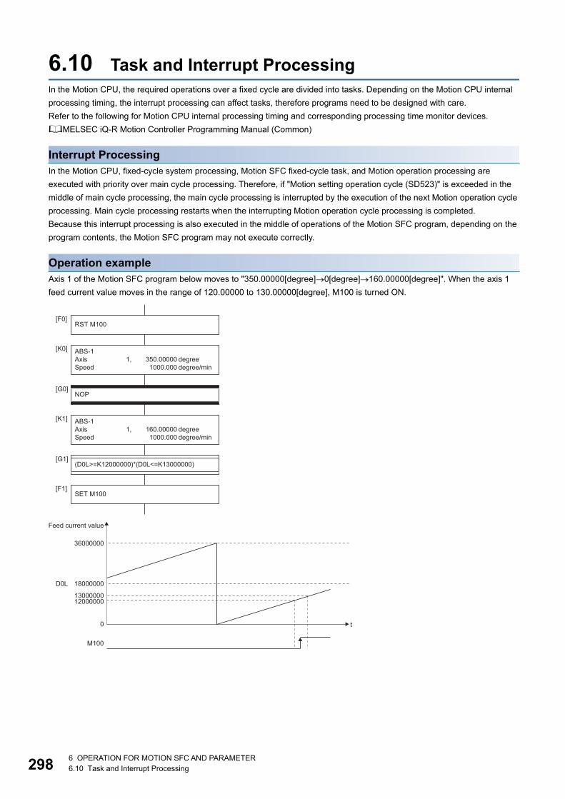
29
6.10 Task and Interrupt ProcessingIn the Motion CPU, the required operations over a fixed cycle are divided into tasks. Depending on the Motion CPU internal
processing timing, the interrupt processing can affect tasks, therefore programs need to be designed with care.
Refer to the following for Motion CPU internal processing timing and corresponding processing time monitor devices.
MELSEC iQ-R Motion Controller Programming Manual (Common)
Interrupt ProcessingIn the Motion CPU, fixed-cycle system processing, Motion SFC fixed-cycle task, and Motion operation processing are
executed with priority over main cycle processing. Therefore, if "Motion setting operation cycle (SD523)" is exceeded in the
middle of main cycle processing, the main cycle processing is interrupted by the execution of the next Motion operation cycle
processing. Main cycle processing restarts when the interrupting Motion operation cycle processing is completed.
Because this interrupt processing is also executed in the middle of operations of the Motion SFC program, depending on the
program contents, the Motion SFC program may not execute correctly.
Operation exampleAxis 1 of the Motion SFC program below moves to "350.00000[degree]0[degree]160.00000[degree]". When the axis 1
feed current value moves in the range of 120.00000 to 130.00000[degree], M100 is turned ON.
ABS-1Axis 1, 160.00000 degreeSpeed 1000.000 degree/min
ABS-1Axis 1, 350.00000 degreeSpeed 1000.000 degree/min
[K0]
[K1]
[G1](D0L>=K12000000)*(D0L<=K13000000)
[G0]NOP
[F1]SET M100
[F0]RST M100
0
18000000
1300000012000000
36000000
Feed current value
t
D0L
M100
86 OPERATION FOR MOTION SFC AND PARAMETER6.10 Task and Interrupt Processing

6
However, when the timing of axis 1 moving from 359.99999[degree] to 0[degree] coincides with the timing of the interrupt
execution processing in the middle of [G1] processing in Motion SFC normal task processing, an unintended operation may
occur.
When using the device whose value changes by the Motion operation cycle in a conditional expression, store the value to a
device and make the program compare values as shown below.
0
36000000
Feed current value
t
(1)Motion SFC normal taskprocessing
Motion operation processing
D0L
(2)
M100
(1) Executing conditional sentence "(D0L>=K12000000)" of [G0](2) Executing conditional sentence "(D0L<=K13000000)" of [G0]
M100 turned ON when D0L is outside the range of 12000000 to 13000000
18000000
1300000012000000
[G1]D8000L=D0L(D8000L>=K12000000)*(D8000L<=K13000000)
ABS-1Axis 1, 160.00000 degreeSpeed 1000.000 degree/min
ABS-1Axis 1, 350.00000 degreeSpeed 1000.000 degree/min
[K0]
[K1]
[G0]NOP
[F1]SET M100
[F0]RST M100
Compare after storing the D0L value to D8000L
6 OPERATION FOR MOTION SFC AND PARAMETER6.10 Task and Interrupt Processing 299

30
7 MOTION SFC FUNCTIONS
7.1 Online Change in the Motion SFC ProgramThis function is used to write to the Motion SFC program to the built-in memory of the Motion CPU during the positioning
control (during "[Rq.1120] PLC ready flag (R: M30000/Q: M2000)" on). When program correction and check of operation is
executed repeatedly, is possible to change program without stopping operation of the Motion CPU. Also, because only the
changed part of the Motion SFC program is written, the writing time is short, and the time it takes to debug is shortened. Data
in which online change is possible are shown below.
: Possible, : Not possible
• Program writing is executed during the positioning control in the online change. Be safely careful enough for
work.
• When a Motion SFC program file, or servo program file is specified in a file transmission at boot that uses a
SD memory card, the intended program operation may not occur depending on if there is an online program
change file or not. Refer to the following for details.
MELSEC iQ-R Motion Controller Programming Manual (Common)
• If the online change is executed simultaneously to one Motion CPU from the multiple personal computers, a
program writing may not be executed. Please do not perform.
• If online changes are executed by another personal computer during the operation of the monitor mode of
the Motion SFC program, debug mode of the Motion SFC program, or test mode in MT Developer2,
injustice of a monitor value and operation failure may occur. Please do not perform.
• If the online change of Motion SFC chart added newly is executed, since the online change of Motion SFC
parameter cannot be executed, it operates as the normal task (default value).
• When performing an online change by changing the range of the command generation axis program in
"Program Allocation Setting" of the servo program editing screen, the changes are not reflected, and online
change is cancelled.
• If the cables between the personal computer and PLC CPU module fall out, or the power supply of the
Multiple CPU system turns OFF or resets, the program is corrupted. Write the program again by the data
writing of MT Developer2.
• The online change only writes when the program being operated by the Motion CPU and the MT
Developer2 project data (before change) match. Before writing perform a check, and when data does not
match, cancel the online change.
Applicable data Online change Remarks
R Series Common Parameter
Motion CPU Common Parameter
Motion Control Parameter
Motion SFC program Motion SFC parameter
Motion SFC chart Online change is possible for the only program during stop.
Operation control step (F/FS)
Transition (G)
Servo program (K) Online change of mode assignment setting is not possible.
Cam data
07 MOTION SFC FUNCTIONS7.1 Online Change in the Motion SFC Program

7
Operating method for the online changeSelect the "Online change OFF/ON" with the online change setting screen displayed by selecting [Tools] [Online Change
Setting] from the MT Developer2 menu bar. The methods for online change of Motion SFC program are shown below.
Online change of the Motion SFC chartOnline change of the Motion SFC chart in edit is executed by selecting button or menu of toolbar. Online change is possible to
the Motion SFC program during stop. If the online change is made to the Motion SFC program during execution, an alarm
message indicates. (Execution/stop state of the Motion SFC program can be checked with the program batch monitor.) If the
start request is made to the Motion SFC program during online change, the moderate error (error code: 32F7H) will occur and
the Motion SFC program does not start.
Target data of online change Operation for online change
Motion SFC chart • Select [Check/Convert] [Write Motion SFC Chart] from the menu bar.
• Click [Write Motion SFC Chart] of toolbar.
Operation control program (F/FS) Click [Convert] of operation control program/transition program editor screen.
Transition program (G)
Servo program (K) Click [Convert] of servo program editor screen.
[Write Motion SFC Chart] menu [Write Motion SFC Chart] icon
7 MOTION SFC FUNCTIONS7.1 Online Change in the Motion SFC Program 301

30
Online change of the operation control/transition programOnline change of the operation control/transition program during edit is executed by selecting the [Convert] button. Online
change is possible to the operation control/transition program during execution. A program that the online change was made
is executed from the next scan.
Operations for which made the online change to the operation control/transition program during execution in the following
conditions are shown below. Be careful to execute the online change in the following conditions.
Program Condition Operation
Online change of the FSn operation control program is
executed during FSn execution in the state of waiting for the
completion of condition for Gn.
After completion of online change, the FSn repeats the
operation control program that the online change was made
until the completion of condition for Gn.
Online change of the Gn program is executed in the state of
waiting for the completion of condition for Gn. (The conditional
sentences of program to write are except the TIME
instruction.)
After completion of online change, the Gn does not transit to
the next step until the completion of condition for program that
the online change was made.
Online change of the Gn program including the TIME
instruction is executed in the state of waiting for the
completion of condition for Gn.
After completion of online change, Gn is ended regardless of
the waiting time of TIME instruction and the next step is
executed.
Online change of the Gn program during the servo program
execution for Kn.
After execution of servo program, the program of changed Gn
is executed.
[Convert] button
FSn
Gn
FSn
Gn
or
Gn
Gn
or
Gn
Gn
or
Kn
Gn
27 MOTION SFC FUNCTIONS7.1 Online Change in the Motion SFC Program

7
Online change of the servo programOnline change of the servo program during edit is executed by selecting the [Convert] button. Online change is possible to the
servo program during execution. A program that the online change was made is executed at the next servo program start.
Operations for which made the online change to the servo program in the following conditions during execution are shown
below. Be careful to execute the online change in the following conditions.
Program Condition Operation
Online change of the servo program Kn at the WAITON or
after WAITOFF is executed in the state of waiting for the
completion of condition for WAITON/WAITOFF.
• After completion of condition for WAITON/WAITOFF, the
servo program before the online change is started.
• The servo program that the online change was made is
executed at the next servo program start.
Online change of the servo program Kn after Gn is executed
in the state of waiting for the completion of condition for Gn.
After completion of condition for Gn, the servo program that
online change was made is executed.
[Convert] button
Kn
Kn
ON bit device
OFF bit device
or
Gn
Kn
Gn
Kn
or
7 MOTION SFC FUNCTIONS7.1 Online Change in the Motion SFC Program 303

30
Reading/Writing of programAn outline of operations used to write the program from MT Developer2 to the program memory of Motion CPU is described
below.
Operation by MT Developer2
■ Reading of program by the reading operation of MT Developer2If reading of program is performed, all files stored in the program folder and all files stored in the online change folder are
read, and a merged program is reflected to the project. (A program configuration is restored in the state that it was being
executed in the Motion CPU.)
■ Writing of program by the writing operation of MT Developer2If writing of program is performed, the program files are updated and stored in the program folder. Also, when an online
change folder exists, the online change folder is deleted.
Program No.0
Program folder
Motion CPU
Program No.2
Program No.5
Program No.6
Program No.100
Online change folder
Program No.0
MT Developer2
Personal computer
Program No.2
Program No.5
Program No.6
Program No.100
Program No.2
Program No.5
Read
Program No.0
Program folder
Motion CPU
Program No.2
Program No.5
Program No.6
Program No.100
Program No.2
Online change folder
Program No.5
Program No.0
MT Developer2
Personal computer
Program No.2
Program No.5
Program No.6
Program No.100
Write
Delete
47 MOTION SFC FUNCTIONS7.1 Online Change in the Motion SFC Program

7
■ Writing of program by the online change operation of MT Developer2If online change is performed, the new program to execute the online change is stored in the online change folder. (Refer to
(1))
After that, the program written in previously is made invalid and the new program is made valid. (Refer to (2))
• The files stored in the program folder and the files stored in the online change folder are managed as a set.
When a program file in the program folder is the target for file transmission at boot function, the contents of
the online change file are also automatically transmitted.
• If the online change is executed repeatedly, the free space in program memory is lost and the online change
may not be executed. In this case, write the program by the writing operation of MT Developer2.
(Writing of program by the writing operation of MT Developer2)
Online change when using file transmission at boot functionWhen a Motion SFC program file, or servo program file is specified in a file transmission at boot that uses a SD memory card,
the intended program operation may not occur depending on if there is an online program change file or not. Refer to the
following for details.
MELSEC iQ-R Motion Controller Programming Manual (Common)
(2) Invalid
Program No.0
Program folder
Motion CPU
Program No.2
Program No.5
Program No.6
Program No.100
Program No.5
Online change folder
Program No.0
MT Developer2
Personal computer
Program No.2
Program No.5
Program No.6
Program No.100
(1) Write
7 MOTION SFC FUNCTIONS7.1 Online Change in the Motion SFC Program 305

30
7.2 Motion SFC Program Monitor and Debug Mode
Motion SFC program monitorThe execution status of Motion SFC programs can be monitored by the Motion SFC program monitor of MT Developer2. The
items that can be monitored are shown below. Refer to the following for details of the Motion SFC program monitor.
Help of MT Developer2
• Execution status list (During execute/During stop/During break)
• Execution status by program (During execute/During stop/During break)
• Active status (Active/Waiting for parallel coupling)
Program executing information can also be checked with special relays (SM), and special registers (SD). Refer to the
following for details.
MELSEC iQ-R Motion Controller Programming Manual (Common)
• Program execution time
• EI/DI status
Debug modeOperation can be checked by placing a break (stop) in any given part of the Motion SFC program, and executing one step in
debug mode. The operations in debug mode are as follows. Refer to the following for details of debug mode.
Help of MT Developer2
• Break point setting (valid/invalid, number of break points)
• Forced break
• One step execution
• Forced transition
• Forced program end
During debug mode "[St.1041] Motion SFC debugging flag (R: M30038/Q: M2038)" is turned ON.
67 MOTION SFC FUNCTIONS7.2 Motion SFC Program Monitor and Debug Mode

A
APPENDICESAppendix 1 Processing Times
Processing time of operation control/Transition instructionThe processing time for the individual instructions are shown below.
Operation processing times can vary substantially depending on the nature of the source and destinations of the instructions,
and the values contained in the following tables should therefore be taken as a set of general guidelines to processing time
rather than as being strictly accurate.
Operation instructions
Classifications Symbol Instruction Operation expression Unit [µs]
Binary operation = Substitution #0=#1 1.5
D800=D801 1.5
U3E1\G10000=U3E1\G10001 2.0
U3E1\HG10000=U3E1\HG10001 1.8
#0L=#2L 1.5
D800L=D802L 1.5
U3E1\G10000L=U3E1\G10002L 2.0
U3E1\HG10000L=U3E1\HG10002L 1.8
#0F=#4F 1.5
D800F=D804F 1.5
U3E1\G10000F=U3E1\G10004F 2.0
U3E1\HG10000F=U3E1\HG10004F 1.8
+ Addition #0=#1+#2 2.2
D800=D801+D802 2.2
U3E1\G10000=U3E1\G10001+U3E1\G10002 4.6
U3E1\HG10000=U3E1\HG10001+U3E1\HG10002 2.8
#0L=#2L+#4L 2.2
D800L=D802L+D804L 2.2
U3E1\G10000L=U3E1\G10002L+U3E1\G10004L 3.2
U3E1\HG10000L=U3E1\HG10002L+U3E1\HG10004L 2.9
#0F=#4F+#8F 2.2
D800F=D804F+D808F 2.2
U3E1\G10000F=U3E1\G10004F+U3E1\G10008F 3.2
U3E1\HG10000F=U3E1\HG10004F+U3E1\HG10008F 2.9
- Subtraction #0=#1-#2 2.2
D800=D801-D802 2.2
U3E1\G10000=U3E1\G10001-U3E1\G10002 3.1
U3E1\HG10000=U3E1\HG10001-U3E1\HG10002 2.8
#0L=#2L-#4L 2.2
D800L=D802L-D804L 2.2
U3E1\G10000L=U3E1\G10002L-U3E1\G10004L 3.2
U3E1\HG10000L=U3E1\HG10002L-U3E1\HG10004L 2.9
#0F=#4F-#8F 2.2
D800F=D804F-D808F 2.2
U3E1\G10000F=U3E1\G10004F-U3E1\G10008F 3.2
U3E1\HG10000F=U3E1\HG10004F-U3E1\HG10008F 2.9
APPENDICESAppendix 1 Processing Times 307

30
Binary operation * Multiplication #0=#1*#2 2.2
D800=D801*D802 2.2
U3E1\G10000=U3E1\G10001*U3E1\G10002 3.1
U3E1\HG10000=U3E1\HG10001*U3E1\HG10002 2.8
#0L=#2L*#4L 2.2
D800L=D802L*D804L 2.2
U3E1\G10000L=U3E1\G10002L*U3E1\G10004L 3.1
U3E1\HG10000L=U3E1\HG10002L*U3E1\HG10004L 2.9
#0F=#4F*#8F 2.2
D800F=D804F*D808F 2.2
U3E1\G10000F=U3E1\G10004F*U3E1\G10008F 3.2
U3E1\HG10000F=U3E1\HG10004F*U3E1\HG10008F 2.9
/ Division #0=#1/#2 2.2
D800=D801/D802 2.2
U3E1\G10000=U3E1\G10001/U3E1\G10002 3.2
U3E1\HG10000=U3E1\HG10001/U3E1\HG10002 2.9
#0L=#2L/#4L 2.2
D800L=D802L/D804L 2.2
U3E1\G10000L=U3E1\G10002L/U3E1\G10004L 3.2
U3E1\HG10000L=U3E1\HG10002L/U3E1\HG10004L 2.9
#0F=#4F/#8F 3.4
D800F=D804F/D808F 3.4
U3E1\G10000F=U3E1\G10004F/U3E1\G10008F 4.8
U3E1\HG10000F=U3E1\HG10004F/U3E1\HG10008F 4.5
% Remainder #0=#1%#2 2.2
D800=D801%D802 2.2
U3E1\G10000=U3E1\G10001%U3E1\G10002 3.2
U3E1\HG10000=U3E1\HG10001%U3E1\HG10002 2.9
#0L=#2L%#4L 2.2
D800L=D802L%D804L 2.2
U3E1\G10000L=U3E1\G10002L%U3E1\G10004L 3.2
U3E1\HG10000L=U3E1\HG10002L%U3E1\HG10004L 2.9
Bit operation ~ Bit inversion
(complement)
#0=~#1 1.6
D800=~D801 1.6
U3E1\G10000=~U3E1\G10001 2.0
U3E1\HG10000=~U3E1\HG10001 1.9
#0L=~#2L 1.6
D800L=~D802L 1.6
U3E1\G10000L=~U3E1\G10002L 2.1
U3E1\HG10000L=~U3E1\HG10002L 1.9
& Bit logical AND #0=#1 2.1
D800=D801&D802 2.1
U3E1\G10000=U3E1\G10001&U3E1\G10002 3.1
U3E1\HG10000=U3E1\HG10001&U3E1\HG10002 2.8
#0L=#2LL 2.1
D800L=D802L&D804L 2.2
U3E1\G10000L=U3E1\G10002L&U3E1\G10004L 3.1
U3E1\HG10000L=U3E1\HG10002L&U3E1\HG10004L 2.8
Classifications Symbol Instruction Operation expression Unit [µs]
8APPENDICESAppendix 1 Processing Times

A
Bit operation | Bit logical OR #0=#1|#2 2.1
D800=D801|D802 2.1
U3E1\G10000=U3E1\G10001|U3E1\G10002 3.1
U3E1\HG10000=U3E1\HG10001|U3E1\HG10002 2.8
#0L=#2L|#4L 2.2
D800L=D802L|D804L 2.2
U3E1\G10000L=U3E1\G10002L|U3E1\G10004L 3.1
U3E1\HG10000L=U3E1\HG10002L|U3E1\HG10004L 2.8
^ Bit exclusive OR #0=#1^#2 2.1
D800=D801^D802 2.1
U3E1\G10000=U3E1\G10001^U3E1\G10002 3.1
U3E1\HG10000=U3E1\HG10001^U3E1\HG10002 2.8
#0L=#2L^#4L 2.2
D800L=D802L^D804L 2.2
U3E1\G10000L=U3E1\G10002L^U3E1\G10004L 3.1
U3E1\HG10000L=U3E1\HG10002L^U3E1\HG10004L 2.8
>> Bit right shift #0=#1>>#2 2.2
D800=D801>>D802 2.1
U3E1\G10000=U3E1\G10001>>U3E1\G10002 3.1
U3E1\HG10000=U3E1\HG10001>>U3E1\HG10002 2.8
#0L=#2L>>#4L 2.2
D800L=D802L>>D804L 2.2
U3E1\G10000L=U3E1\G10002L>>U3E1\G10004L 3.1
U3E1\HG10000L=U3E1\HG10002L>>U3E1\HG10004L 2.8
<< Bit left shift #0=#1<<#2 2.1
D800=D801<<D802 2.1
U3E1\G10000=U3E1\G10001<<U3E1\G10002 3.1
U3E1\HG10000=U3E1\HG10001<<U3E1\HG10002 2.8
#0L=#2L<<#4L 2.2
D800L=D802L<<D804L 2.2
U3E1\G10000L=U3E1\G10002L<<U3E1\G10004L 3.2
U3E1\HG10000L=U3E1\HG10002L<<U3E1\HG10004L 2.8
Sign - Sign inversion
(complement of 2)
#0=-#1 1.6
D800=-D812 1.6
U3E1\G10000=-U3E1\G10001 2.1
U3E1\HG10000=-U3E1\HG10001 1.9
#0L=-#2L 1.6
D800L=-D802L 1.6
U3E1\G10000L=-U3E1\G10002L 2.1
U3E1\HG10000L=-U3E1\HG10002L 1.9
#0F=-#4F 2.5
D800F=-D804F 2.4
U3E1\G10000F=-U3E1\G10004F 2.9
U3E1\HG10000F=-U3E1\HG10004F 2.8
Classifications Symbol Instruction Operation expression Unit [µs]
APPENDICESAppendix 1 Processing Times 309

31
Standard function SIN Sine #0F=SIN(#4F) 4.7
D800F=SIN(D804F) 4.6
U3E1\G10000F=SIN(U3E1\G10004F) 5.8
U3E1\HG10000F=SIN(U3E1\HG10004F) 5.6
COS Cosine #0F=COS(#4F) 4.6
D800F=COS(D804F) 4.6
U3E1\G10000F=COS(U3E1\G10004F) 5.8
U3E1\HG10000F=COS(U3E1\HG10004F) 5.6
TAN Tangent #0F=TAN(#4F) 4.7
D800F=TAN(D804F) 4.7
U3E1\G10000F=TAN(U3E1\G10004F) 6.0
U3E1\HG10000F=TAN(U3E1\HG10004F) 5.8
ASIN Arcsine #0F=ASIN(#4F) 7.6
D800F=ASIN(D804F) 7.5
U3E1\G10000F=ASIN(U3E1\G10004F) 8.4
U3E1\HG10000F=ASIN(U3E1\HG10004F) 8.2
ACOS Arccosine #0F=ACOS(#4F) 5.3
D800F=ACOS(D804F) 5.3
U3E1\G10000F=ACOS(U3E1\G10004F) 6.1
U3E1\HG10000F=ACOS(U3E1\HG10004F) 6.1
ATAN Arctangent #0F=ATAN(#4F) 6.0
D800F=ATAN(D804F) 6.0
U3E1\G10000F=ATAN(U3E1\G10004F) 6.8
U3E1\HG10000F=ATAN(U3E1\HG10004F) 6.8
SQRT Square root #0F=SQRT(#4F) 3.9
D800F=SQRT(D804F) 3.9
U3E1\G10000F=SQRT(U3E1\G10004F) 4.8
U3E1\HG10000F=SQRT(U3E1\HG10004F) 4.7
LN Natural logarithm #0F=LN(#4F) 4.1
D800F=LN(D804F) 4.1
U3E1\G10000F=LN(U3E1\G10004F) 5.4
U3E1\HG10000F=LN(U3E1\HG10004F) 5.2
EXP Exponential
operation
#0F=EXP(#4F) 14.2
D800F=EXP(D804F) 14.2
U3E1\G10000F=EXP(U3E1\G10004F) 15.6
U3E1\HG10000F=EXP(U3E1\HG10004F) 15.4
ABS Absolute value #0F=ABS(#4F) 1.6
D800F=ABS(D804F) 1.6
U3E1\G10000F=ABS(U3E1\G10004F) 2.1
U3E1\HG10000F=ABS(U3E1\HG10004F) 1.9
RND Round-off #0F=RND(#4F) 3.5
D800F=RND(D804F) 3.5
U3E1\G10000F=RND(U3E1\G10004F) 4.0
U3E1\HG10000F=RND(U3E1\HG10004F) 3.8
FIX Round-down #0F=FIX(#4F) 2.5
D800F=FIX(D804F) 2.5
U3E1\G10000F=FIX(U3E1\G10004F) 3.0
U3E1\HG10000F=FIX(U3E1\HG10004F) 2.8
FUP Round-up #0F=FUP(#4F) 2.5
D800F=FUP(D804F) 2.5
U3E1\G10000F=FUP(U3E1\G10004F) 3.0
U3E1\HG10000F=FUP(U3E1\HG10004F) 2.8
Classifications Symbol Instruction Operation expression Unit [µs]
0APPENDICESAppendix 1 Processing Times

A
Standard function BIN BCD BIN
conversion
#0=BIN(#1) 1.6
D800=BIN(D801) 1.6
U3E1\G10000=BIN(U3E1\G10001) 2.1
U3E1\HG10000=BIN(U3E1\HG10001) 1.9
#0L=BIN(#2L) 1.7
D800L=BIN(D802L) 1.7
U3E1\G10000L=BIN(U3E1\G10002L) 2.2
U3E1\HG10000L=BIN(U3E1\HG10002L) 2.0
BCD BIN BCD
conversion
#0=BCD(#1) 1.7
D800=BCD(D801) 1.7
U3E1\G10000=BCD(U3E1\G10001) 2.2
U3E1\HG10000=BCD(U3E1\HG10001) 2.0
#0L=BCD(#2L) 1.8
D800L=BCD(D802L) 1.8
U3E1\G10000L=BCD(U3E1\G10002L) 2.3
U3E1\HG10000L=BCD(U3E1\HG10002L) 2.1
Data control SCL 16-bit integer type
scaling
SCL K0,K2000,#0,#2002*1 6.9
SCL K0,K2000,D2000,D4002*1 6.9
SCL K0,K2000,U3E1\G10000,U3E1\G12002*1 17.4
SCL K0,K2000,U3E1\HG0,U3E1\HG12002*1 14.8
SCL K0,K2000,#0,#2002*2 43.1
SCL K0,K2000,D2000,D4002*2 43.1
SCL K0,K2000,U3E1\G10000,U3E1\G12002*2 133.6
SCL K0,K2000,U3E1\HG0,U3E1\HG12002*2 110.9
SCL K0,K2000,#0,#2002*3 405.4
SCL K0,K2000,D2000,D4002*3 405.3
SCL K0,K2000,U3E1\G10000,U3E1\G12002*3 1298.1
SCL K0,K2000,U3E1\HG0,U3E1\HG12002*3 1093.9
SCL K2,K1,#0,#2002*1 4.5
SCL K2,K1,D2000,D4002*1 4.6
SCL K2,K1,U3E1\G10000,U3E1\G12002*1 9.6
SCL K2,K1,U3E1\HG0,U3E1\HG12002*1 8.3
DSCL 32-bit integer type
scaling
DSCL K0,K2000L,#0,#4002L*1 6.9
DSCL K0,K2000L,D2000,D6002L*1 6.9
DSCL K0,K2000L,U3E1\G10000,U3E1\G14002L*1 17.4
DSCL K0,K2000L,U3E1\HG0,U3E1\HG12002L*1 14.6
DSCL K0,K2000L,#0,#4002L*2 42.8
DSCL K0,K2000L,D2000,D6002L*2 43.5
DSCL K0,K2000L,U3E1\G10000,U3E1\G14002L*2 135.9
DSCL K0,K2000L,U3E1\HG0,U3E1\HG12002L*2 111.0
DSCL K0,K2000L,#0,#4002L*3 415.4
DSCL K0,K2000L,D2000,D6002L*3 415.3
DSCL K0,K2000L,U3E1\G10000,U3E1\G14002L*3 1306.0
DSCL K0,K2000L,U3E1\HG0,U3E1\HG12002L*3 1074.1
DSCL K2,K1L,#0,#4002L*1 4.6
DSCL K2,K1L,D2000,D6002L*1 4.6
DSCL K2,K1L,U3E1\G10000,U3E1\G14002L*1 9.8
DSCL K2,K1L,U3E1\HG0,U3E1\HG12002L*1 8.3
Classifications Symbol Instruction Operation expression Unit [µs]
APPENDICESAppendix 1 Processing Times 311

31
Type conversion SHORT Converted into 16-
bit integer type
(signed)
#0=SHORT(#2L) 1.6
D800=SHORT(D802L) 1.6
U3E1\G10000=SHORT(U3E1\G10002L) 2.1
U3E1\HG10000=SHORT(U3E1\HG10002L) 1.9
#0=SHORT(#4F) 1.7
D800=SHORT(D804F) 1.7
U3E1\G10000=SHORT(U3E1\G10004F) 2.2
U3E1\HG10000=SHORT(U3E1\HG10004F) 2.0
USHORT Converted into 16-
bit integer type
(unsigned)
#0=USHORT(#2L) 1.6
D800=USHORT(D802L) 1.6
U3E1\G10000=USHORT(U3E1\G10002L) 2.1
U3E1\HG10000=USHORT(U3E1\HG10002L) 1.9
#0=USHORT(#4F) 1.7
D800=USHORT(D804F) 1.7
U3E1\G10000=USHORT(U3E1\G10004F) 2.2
U3E1\HG10000=USHORT(U3E1\HG10004F) 2.0
LONG Converted into 32-
bit integer type
(signed)
#0L=LONG(#2) 1.6
D800L=LONG(D802) 1.6
U3E1\G10000L=LONG(U3E1\G10002) 2.1
U3E1\HG10000L=LONG(U3E1\HG10002) 1.9
#0L=LONG(#4F) 1.7
D800L=LONG(D804F) 1.7
U3E1\G10000L=LONG(U3E1\G10004F) 2.2
U3E1\HG10000L=LONG(U3E1\HG10004F) 2.0
ULONG Converted into 32-
bit integer type
(unsigned)
#0L=ULONG(#2) 1.6
D800L=ULONG(D802) 1.6
U3E1\G10000L=ULONG(U3E1\G10002) 2.1
U3E1\HG10000L=ULONG(U3E1\HG10002) 1.9
#0L=ULONG(#4F) 1.7
D800L=ULONG(D804F) 1.7
U3E1\G10000L=ULONG(U3E1\G10004F) 2.2
U3E1\HG10000L=ULONG(U3E1\HG10004F) 2.0
FLOAT Converted into 64-
bit floating point
type (signed)
#0F=FLOAT(#4) 1.6
D800F=FLOAT(D804) 1.6
U3E1\G10000F=FLOAT(U3E1\G10004) 2.1
U3E1\HG10000F=FLOAT(U3E1\HG10004) 1.9
#0F=FLOAT(#4L) 1.6
D800F=FLOAT(D804L) 1.6
U3E1\G10000F=FLOAT(U3E1\G10004L) 2.1
U3E1\HG10000F=FLOAT(U3E1\HG10004L) 1.9
UFLOAT Converted into 64-
bit floating point
type (unsigned)
#0F=UFLOAT(#4) 1.6
D800F=UFLOAT(D804) 1.6
U3E1\G10000F=UFLOAT(U3E1\G10004) 2.1
U3E1\HG10000F=UFLOAT(U3E1\HG10004) 1.9
#0F=UFLOAT(#4L) 1.6
D800F=UFLOAT(D804L) 1.6
U3E1\G10000F=UFLOAT(U3E1\G10004L) 2.1
U3E1\HG10000F=UFLOAT(U3E1\HG10004L) 1.9
DFLT Floating-point
value conversion
32-bit into 64-bit
#0F=DFLT(#4L) 1.6
D2000F=DFLT(D2004L) 1.6
U3E1\G10000F=DFLT(U3E1\G10004L) 2.1
U3E1\HG10000F=DFLT(U3E1\HG100004L) 2.0
Classifications Symbol Instruction Operation expression Unit [µs]
2APPENDICESAppendix 1 Processing Times

A
Type conversion SFLT Floating-point
value conversion
64-bit into 32-bit
#0L=SFLT(#2F) 1.7
D2000L=SFLT(D2002F) 1.7
U3E1\G10000L=SFLT(U3E1\G10002F) 2.6
U3E1\HG10000L=SFLT(U3E1\HG10002F) 2.4
Bit device status (None) ON (normally
open contact)
(Completion of
condition)
SET M1000=M0 1.4
SET M1000=X100 1.5
SET M1000=X20*4 4.6
SET M1000=U3E1\G10000.0 2.0
SET M1000=U3E1\HG10000.0 1.8
! OFF (normally
closed contact)
(Completion of
condition)
SET M1000=!M0 1.5
SET M1000=!X100 1.6
SET M1000=!X20*4 4.7
SET M1000=!U3E1\G10000.0 2.0
SET M1000=!U3E1\HG10000.0 1.9
Bit device control SET Device set SET M1000 0.9
SET Y100 0.9
SET Y60*4 3.2
SET U3E1\G11000.0 1.5
SET U3E1\HG11000.0 1.4
RST Device reset RST M1000 0.9
RST Y100 0.9
RST Y60*4 3.2
RST U3E1\G11000.0 1.5
RST U3E1\HG11000.0 1.4
DOUT Device output DOUT M0,#0 1.5
DOUT Y100,#0 1.5
DOUT Y60,#0*4 4.0
DOUT M0,#0L 1.5
DOUT Y100,#0L 1.5
DOUT Y60,#0L*4 4.1
DIN Device input DIN #0,M0 1.5
DIN #0,X0 1.5
DIN #0,X20*4 6.2
DIN #0L,M0 1.5
DIN #0L,X0 1.6
DIN #0L,X20*4 6.5
OUT Bit device output OUT M100=M0 1.4
OUT Y0=M0 1.5
OUT Y60=M0*4 3.8
OUT U3E1\G10000.0=M0 2.1
OUT U3E1\HG10000.0=M0 1.9
Logical operation * Logical AND SET M1000=M0*M1 2.0
SET M1000=X100*X101 1.7
SET M1000=X20*X21*4 9.5
SET M1000=U3E1\G10000.0*U3E1\G10000.1 2.6
SET M1000=U3E1\HG10000.0*U3E1\HG10000.1 2.3
+ Logical OR SET M1000=M0+M1 2.0
SET M1000=X100+X101 1.7
SET M1000=X20+X21*4 9.4
SET M1000=U3E1\G10000.0+U3E1\G10000.1 3.1
SET M1000=U3E1\HG10000.0+U3E1\HG10000.1 2.9
Classifications Symbol Instruction Operation expression Unit [µs]
APPENDICESAppendix 1 Processing Times 313
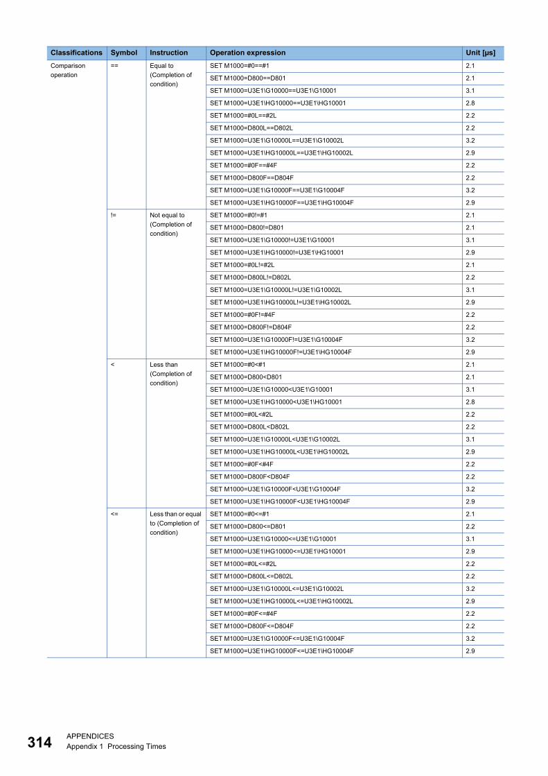
31
Comparison
operation
== Equal to
(Completion of
condition)
SET M1000=#0==#1 2.1
SET M1000=D800==D801 2.1
SET M1000=U3E1\G10000==U3E1\G10001 3.1
SET M1000=U3E1\HG10000==U3E1\HG10001 2.8
SET M1000=#0L==#2L 2.2
SET M1000=D800L==D802L 2.2
SET M1000=U3E1\G10000L==U3E1\G10002L 3.2
SET M1000=U3E1\HG10000L==U3E1\HG10002L 2.9
SET M1000=#0F==#4F 2.2
SET M1000=D800F==D804F 2.2
SET M1000=U3E1\G10000F==U3E1\G10004F 3.2
SET M1000=U3E1\HG10000F==U3E1\HG10004F 2.9
!= Not equal to
(Completion of
condition)
SET M1000=#0!=#1 2.1
SET M1000=D800!=D801 2.1
SET M1000=U3E1\G10000!=U3E1\G10001 3.1
SET M1000=U3E1\HG10000!=U3E1\HG10001 2.9
SET M1000=#0L!=#2L 2.1
SET M1000=D800L!=D802L 2.2
SET M1000=U3E1\G10000L!=U3E1\G10002L 3.1
SET M1000=U3E1\HG10000L!=U3E1\HG10002L 2.9
SET M1000=#0F!=#4F 2.2
SET M1000=D800F!=D804F 2.2
SET M1000=U3E1\G10000F!=U3E1\G10004F 3.2
SET M1000=U3E1\HG10000F!=U3E1\HG10004F 2.9
< Less than
(Completion of
condition)
SET M1000=#0<#1 2.1
SET M1000=D800<D801 2.1
SET M1000=U3E1\G10000<U3E1\G10001 3.1
SET M1000=U3E1\HG10000<U3E1\HG10001 2.8
SET M1000=#0L<#2L 2.2
SET M1000=D800L<D802L 2.2
SET M1000=U3E1\G10000L<U3E1\G10002L 3.1
SET M1000=U3E1\HG10000L<U3E1\HG10002L 2.9
SET M1000=#0F<#4F 2.2
SET M1000=D800F<D804F 2.2
SET M1000=U3E1\G10000F<U3E1\G10004F 3.2
SET M1000=U3E1\HG10000F<U3E1\HG10004F 2.9
<= Less than or equal
to (Completion of
condition)
SET M1000=#0<=#1 2.1
SET M1000=D800<=D801 2.2
SET M1000=U3E1\G10000<=U3E1\G10001 3.1
SET M1000=U3E1\HG10000<=U3E1\HG10001 2.9
SET M1000=#0L<=#2L 2.2
SET M1000=D800L<=D802L 2.2
SET M1000=U3E1\G10000L<=U3E1\G10002L 3.2
SET M1000=U3E1\HG10000L<=U3E1\HG10002L 2.9
SET M1000=#0F<=#4F 2.2
SET M1000=D800F<=D804F 2.2
SET M1000=U3E1\G10000F<=U3E1\G10004F 3.2
SET M1000=U3E1\HG10000F<=U3E1\HG10004F 2.9
Classifications Symbol Instruction Operation expression Unit [µs]
4APPENDICESAppendix 1 Processing Times

A
Comparison
operation
> More than
(Completion of
condition)
SET M1000=#0>#1 2.1
SET M1000=D800>D801 2.1
SET M1000=U3E1\G10000>U3E1\G10001 3.1
SET M1000=U3E1\HG10000>U3E1\HG10001 2.9
SET M1000=#0L>#2L 2.1
SET M1000=D800L>D802L 2.1
SET M1000=U3E1\G10000L>U3E1\G10002L 3.1
SET M1000=U3E1\HG10000L>U3E1\HG10002L 2.9
SET M1000=#0F>#4F 2.2
SET M1000=D800F>D804F 2.2
SET M1000=U3E1\G10000F>U3E1\G10004F 3.2
SET M1000=U3E1\HG10000F>U3E1\HG10004F 2.9
>= More than or
equal to
(Completion of
condition)
SET M1000=#0>=#1 2.1
SET M1000=D800>=D801 2.1
SET M1000=U3E1\G10000>=U3E1\G10001 3.1
SET M1000=U3E1\HG10000>=U3E1\HG10001 2.8
SET M1000=#0L>=#2L 2.1
SET M1000=D800L>=D802L 2.1
SET M1000=U3E1\G10000L>=U3E1\G10002L 3.2
SET M1000=U3E1\HG10000L>=U3E1\HG10002L 2.9
SET M1000=#0F>=#4F 2.2
SET M1000=D800F>=D804F 2.2
SET M1000=U3E1\G10000F>=U3E1\G10004F 3.2
SET M1000=U3E1\HG10000F>=U3E1\HG10004F 2.9
Classifications Symbol Instruction Operation expression Unit [µs]
APPENDICESAppendix 1 Processing Times 315

31
Program control IF-ELSE-
IEND
Conditional
branch control
IF #0==#1*5
#2=#3
ELSE
#4=#5
IEND
3.3
IF D800==D801*5
#2=#3
ELSE
#4=#5
IEND
1.6
IF U3E1\G10000==U3E1\G10001*5
#2=#3
ELSE
#4=#5
IEND
2.1
IF U3E1\HG10000==U3E1\HG10001*5
#2=#3
ELSE
#4=#5
IEND
2.0
IF #0==#1*6
#2=#3
ELSE
#4=#5
IEND
1.6
IF D800==D801*6
#2=#3
ELSE
#4=#5
IEND
1.6
IF U3E1\G10000==U3E1\G10001*6
#2=#3
ELSE
#4=#5
IEND
2.1
IF U3E1\HG10000==U3E1\HG10001*6
#2=#3
ELSE
#4=#5
IEND
2.0
Classifications Symbol Instruction Operation expression Unit [µs]
6APPENDICESAppendix 1 Processing Times

A
Program control SELECT-
CASE-
SEND
Selective branch
control
SELECT*7
CASE #0==K1
#2=#3
CEND
CASE #1==K1
#4=#5
CEND
CELSE
#6=#7
CEND
SEND
3.1
SELECT*7
CASE D800==K1
#2=#3
CEND
CASE D801==K1
#4=#5
CEND
CELSE
#6=#7
CEND
SEND
0.8
SELECT*7
CASE U3E1\G10000==K1
#2=#3
CEND
CASE U3E1\G10001==K1
#4=#5
CEND
CELSE
#6=#7
CEND
SEND
0.9
SELECT*7
CASE U3E1\HG10000==K1
#2=#3
CEND
CASE U3E1\HG10001==K1
#4=#5
CEND
CELSE
#6=#7
CEND
SEND
0.9
SELECT*8
CASE #0==K1
#2=#3
CEND
CASE #1==K1
#4=#5
CEND
CELSE
#6=#7
CEND
SEND
1.0
SELECT*8
CASE D800==K1
#2=#3
CEND
CASE D801==K1
#4=#5
CEND
CELSE
#6=#7
CEND
SEND
1.0
Classifications Symbol Instruction Operation expression Unit [µs]
APPENDICESAppendix 1 Processing Times 317

31
Program control SELECT-
CASE-
SEND
Selective branch
control
SELECT*8
CASE U3E1\G10000==K1
#2=#3
CEND
CASE U3E1\G10001==K1
#4=#5
CEND
CELSE
#6=#7
CEND
SEND
1.3
SELECT*8
CASE U3E1\HG10000==K1
#2=#3
CEND
CASE U3E1\HG10001==K1
#4=#5
CEND
CELSE
#6=#7
CEND
SEND
1.2
SELECT*9
CASE #0==K1
#2=#3
CEND
CASE #1==K1
#4=#5
CEND
CELSE
#6=#7
CEND
SEND
1.1
SELECT*9
CASE D800==K1
#2=#3
CEND
CASE D801==K1
#4=#5
CEND
CELSE
#6=#7
CEND
SEND
1.1
SELECT*9
CASE U3E1\G10000==K1
#2=#3
CEND
CASE U3E1\G10001==K1
#4=#5
CEND
CELSE
#6=#7
CEND
SEND
1.4
SELECT*9
CASE U3E1\HG10000==K1
#2=#3
CEND
CASE U3E1\HG10001==K1
#4=#5
CEND
CELSE
#6=#7
CEND
SEND
1.3
Classifications Symbol Instruction Operation expression Unit [µs]
8APPENDICESAppendix 1 Processing Times
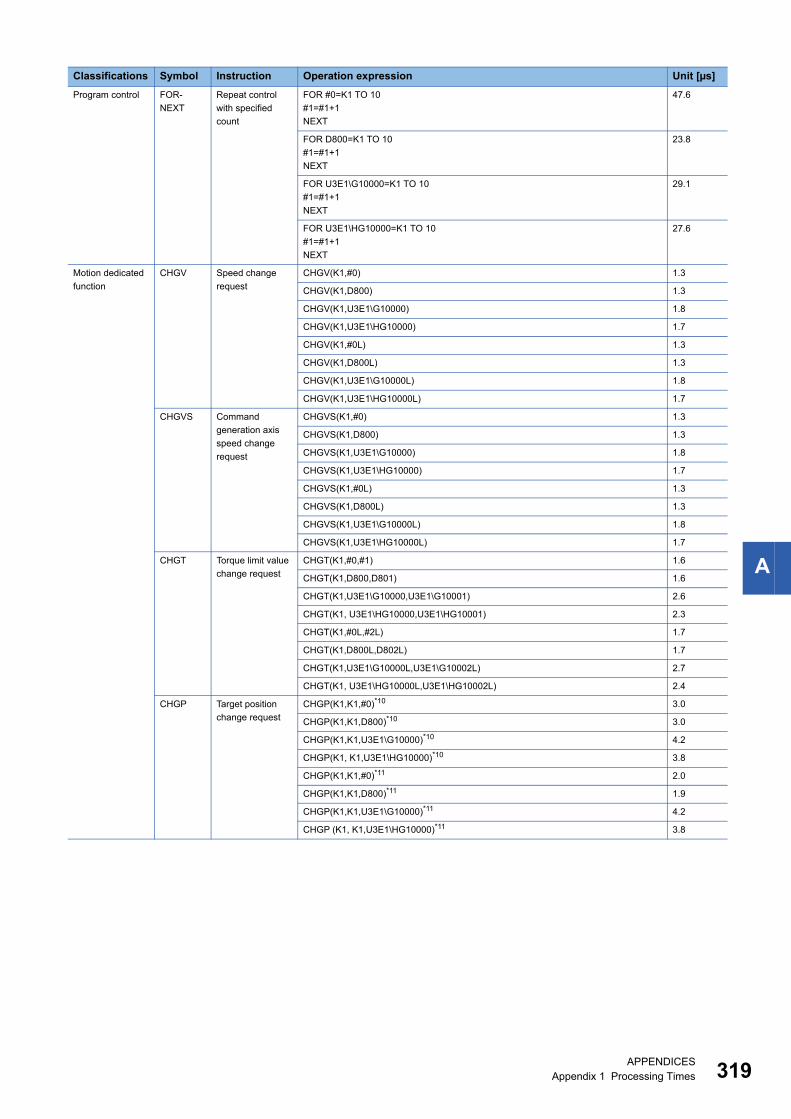
A
Program control FOR-
NEXT
Repeat control
with specified
count
FOR #0=K1 TO 10
#1=#1+1
NEXT
47.6
FOR D800=K1 TO 10
#1=#1+1
NEXT
23.8
FOR U3E1\G10000=K1 TO 10
#1=#1+1
NEXT
29.1
FOR U3E1\HG10000=K1 TO 10
#1=#1+1
NEXT
27.6
Motion dedicated
function
CHGV Speed change
request
CHGV(K1,#0) 1.3
CHGV(K1,D800) 1.3
CHGV(K1,U3E1\G10000) 1.8
CHGV(K1,U3E1\HG10000) 1.7
CHGV(K1,#0L) 1.3
CHGV(K1,D800L) 1.3
CHGV(K1,U3E1\G10000L) 1.8
CHGV(K1,U3E1\HG10000L) 1.7
CHGVS Command
generation axis
speed change
request
CHGVS(K1,#0) 1.3
CHGVS(K1,D800) 1.3
CHGVS(K1,U3E1\G10000) 1.8
CHGVS(K1,U3E1\HG10000) 1.7
CHGVS(K1,#0L) 1.3
CHGVS(K1,D800L) 1.3
CHGVS(K1,U3E1\G10000L) 1.8
CHGVS(K1,U3E1\HG10000L) 1.7
CHGT Torque limit value
change request
CHGT(K1,#0,#1) 1.6
CHGT(K1,D800,D801) 1.6
CHGT(K1,U3E1\G10000,U3E1\G10001) 2.6
CHGT(K1, U3E1\HG10000,U3E1\HG10001) 2.3
CHGT(K1,#0L,#2L) 1.7
CHGT(K1,D800L,D802L) 1.7
CHGT(K1,U3E1\G10000L,U3E1\G10002L) 2.7
CHGT(K1, U3E1\HG10000L,U3E1\HG10002L) 2.4
CHGP Target position
change request
CHGP(K1,K1,#0)*10 3.0
CHGP(K1,K1,D800)*10 3.0
CHGP(K1,K1,U3E1\G10000)*10 4.2
CHGP(K1, K1,U3E1\HG10000)*10 3.8
CHGP(K1,K1,#0)*11 2.0
CHGP(K1,K1,D800)*11 1.9
CHGP(K1,K1,U3E1\G10000)*11 4.2
CHGP (K1, K1,U3E1\HG10000)*11 3.8
Classifications Symbol Instruction Operation expression Unit [µs]
APPENDICESAppendix 1 Processing Times 319

32
Motion dedicated
function
MCNST Machine program
operation start
request
MCNST(#13000,#12998)*12 153.2
MCNST(D58000,D57998)*12 144.0
MCNST(U3E1\G10002,U3E1\G10000)*12 165.2
MCNST(U3E1\HG5002,U3E1\HG5000)*12 160.6
MCNST(#13000,#12998)*13 1187.7
MCNST(D58000,D57998)*13 1195.1
MCNST(U3E1\G10002,U3E1\G10000)*13 2221.8
MCNST(U3E1\HG5002,U3E1\HG5000)*13 2050.2
MCNST(#13000,#12998)*14 1485.0
MCNST(D58000,D57998)*14 1487.7
MCNST(U3E1\G10002,U3E1\G10000)*14 3470.5
MCNST(U3E1\HG5002,U3E1\HG5000)*14 3194.7
Advanced
synchronous
control dedicated
function
CAMRD Cam data read CAMRD #0,#2L,K256,#4*15 52.0
CAMRD D2000,D2002L,K256,D2004*15 46.1
CAMRD U3E1\G10000,U3E1\G10002L,K256,U3E1\G10004*15 19.5
CAMRD U3E1\HG10000,U3E1\HG10002L,K256,U3E1\HG0*15 19.2
CAMRD #0,#2L,K1024,#4*15 190.5
CAMRD D2000,D2002L,K1024,D2004*15 191.0
CAMRD U3E1\G10000,U3E1\G10002L,K1024,U3E1\G10004*15 58.6
CAMRD U3E1\HG10000,U3E1\HG10002L,K1024,U3E1\HG0*15 58.2
CAMRD #0,#2L,K2048,#4*15 382.5
CAMRD D2000,D2002L,K2048,D2004*15 383.1
CAMRD U3E1\G10000,U3E1\G10002L,K2048,U3E1\G10004*15 113.0
CAMRD U3E1\HG10000,U3E1\HG10002L,K2048,U3E1\HG0*15 112.9
CAMRD #0,#2L,K256,#4*16 95.0
CAMRD D2000,D2002L,K256,D2004*16 94.2
CAMRD U3E1\G10000,U3E1\G10002L,K256,U3E1\G10004*16 31.2
CAMRD U3E1\HG10000,U3E1\HG10002L,K256,U3E1\HG0*16 31.0
CAMRD #0,#2L,K512,#4*16 190.6
CAMRD D2000,D2002L,K512,D2004*16 191.0
CAMRD U3E1\G10000,U3E1\G10002L,K512,U3E1\G10004*16 58.6
CAMRD U3E1\HG10000,U3E1\HG10002L,K512,U3E1\HG0*16 58.3
CAMRD #0,#2L,K1024,#4*16 382.4
CAMRD D2000,D2002L,K1024,D2004*16 383.1
CAMRD U3E1\G10000,U3E1\G10002L,K1024,U3E1\G10004*16 113.3
CAMRD U3E1\HG10000,U3E1\HG10002L,K1024,U3E1\HG0*16 113.0
Classifications Symbol Instruction Operation expression Unit [µs]
0APPENDICESAppendix 1 Processing Times

A
Advanced
synchronous
control dedicated
function
CAMWR Cam data write CAMWR #0,#2L,K256,#4,H401*15 27.3
CAMWR D2000,D2002L,K256,D2004,H401*15 27.1
CAMWR U3E1\G10000,U3E1\G10002L,K256,U3E1\G10004,H401*15 107.2
CAMWR U3E1\HG10000,U3E1\HG10002L,K256,U3E1\HG0,H401*15 93.1
CAMWR #0,#2L,K1024,#4,H401*15 74.5
CAMWR D2000,D2002L,K1024,D2004,H401*15 72.0
CAMWR U3E1\G10000,U3E1\G10002L,K1024,U3E1\G10004,H401*15 362.1
CAMWR U3E1\HG10000,U3E1\HG10002L,K1024,U3E1\HG0,H401*15 308.5
CAMWR #0,#2L,K2048,#4,H401*15 137.6
CAMWR D2000,D2002L,K2048,D2004,H401*15 135.8
CAMWR U3E1\G10000,U3E1\G10002L,K2048,U3E1\G10004,H401*15 702.1
CAMWR U3E1\HG10000,U3E1\HG10002L,K2048,U3E1\HG0,H401*15 596.6
CAMWR #0,#2L,K256,#4,H401*16 45.1
CAMWR D2000,D2002L,K256,D2004,H401*16 46.0
CAMWR U3E1\G10000,U3E1\G10002L,K256,U3E1\G10004,H401*16 196.9
CAMWR U3E1\HG10000,U3E1\HG10002L,K256,U3E1\HG0,H401*16 169.7
CAMWR #0,#2L,K512,#4,H401*16 81.8
CAMWR D2000,D2002L,K512,D2004,H401*16 81.0
CAMWR U3E1\G10000,U3E1\G10002L,K512,U3E1\G10004,H401*16 370.6
CAMWR U3E1\HG10000,U3E1\HG10002L,K512,U3E1\HG0,H401*16 317.5
CAMWR #0,#2L,K1024,#4,H401*16 153.4
CAMWR D2000,D2002L,K1024,D2004,H401*16 152.6
CAMWR U3E1\G10000,U3E1\G10002L,K1024,U3E1\G10004,H401*16 719.9
CAMWR U3E1\HG10000,U3E1\HG10002L,K1024,U3E1\HG0,H401*16 614.3
CAMWR Cam data write
(Cam open area)
CAMWR #0,#2L,K256,#4,H0*15 23.5
CAMWR D2000,D2002L,K256,D2004,H0*15 20.4
CAMWR U3E1\G10000,U3E1\G10002L,K256,U3E1\G10004,H0*15 100.6
CAMWR U3E1\HG10000,U3E1\HG10002L,K256,U3E1\HG0,H0*15 86.3
CAMWR #0,#2L,K1024,#4,H0*15 67.4
CAMWR D2000,D2002L,K1024,D2004,H0*15 63.1
CAMWR U3E1\G10000,U3E1\G10002L,K1024,U3E1\G10004,H0*15 348.7
CAMWR U3E1\HG10000,U3E1\HG10002L,K1024,U3E1\HG0,H0*15 294.9
CAMWR #0,#2L,K2048,#4,H0*15 128.1
CAMWR D2000,D2002L,K2048,D2004,H0*15 123.5
CAMWR U3E1\G10000,U3E1\G10002L,K2048,U3E1\G10004,H0*15 684.8
CAMWR U3E1\HG10000,U3E1\HG10002L,K2048,U3E1\HG0,H0*15 578.6
CAMWR #0,#2L,K256,#4,H0*16 39.2
CAMWR D2000,D2002L,K256,D2004,H0*16 38.4
CAMWR U3E1\G10000,U3E1\G10002L,K256,U3E1\G10004,H0*16 184.9
CAMWR U3E1\HG10000,U3E1\HG10002L,K256,U3E1\HG0,H0*16 157.4
CAMWR #0,#2L,K512,#4,H0*16 72.6
CAMWR D2000,D2002L,K512,D2004,H0*16 71.3
CAMWR U3E1\G10000,U3E1\G10002L,K512,U3E1\G10004,H0*16 356.1
CAMWR U3E1\HG10000,U3E1\HG10002L,K512,U3E1\HG0,H0*16 302.7
CAMWR #0,#2L,K1024,#4,H0*16 139.9
CAMWR D2000, D2002L, K1024, D2004,H0*16 138.7
CAMWR U3E1\G10000,U3E1\G10002L,K1024,U3E1\G10004,H0*16 700.1
CAMWR U3E1\HG10000,U3E1\HG10002L,K1024,U3E1\HG0,H0*16 594.0
Classifications Symbol Instruction Operation expression Unit [µs]
APPENDICESAppendix 1 Processing Times 321

32
Advanced
synchronous
control dedicated
function
CAMMK Cam auto-
generation
CAMMK #0,#1,#2*17 275.6
CAMMK D2000,D2001,D2002*17 258.3
CAMMK U3E1\G10000,U3E1\G10001,U3E1\G10002*17 263.0
CAMMK U3E1\HG10000,U3E1\HG10001,U3E1\HG10002*17 262.0
CAMMK #0,#1,#2*18 7981.1
CAMMK D2000,D2001,D2002*18 7938.2
CAMMK U3E1\G10000,U3E1\G10001,U3E1\G10002*18 7928.1
CAMMK U3E1\HG10000,U3E1\HG10001,U3E1\HG10002*18 7927.5
CAMMK #0,#1,#2*19 31856.3
CAMMK D2000,D2001,D2002*19 31717.5
CAMMK U3E1\G10000,U3E1\G10001,U3E1\G10002*19 31664.8
CAMMK U3E1\HG10000,U3E1\HG10001,U3E1\HG10002*19 31667.4
CAMMK #0,#1,#2*20 1249.2
CAMMK D2000,D2001,D2002*20 1130.7
CAMMK U3E1\G10000,U3E1\G10001,U3E1\G10002*20 1144.3
CAMMK U3E1\HG10000,U3E1\HG10001,U3E1\HG10002*20 1141.0
CAMMK #0,#1,#2*21 29793.0
CAMMK D2000,D2001,D2002*21 29754.1
CAMMK U3E1\G10000,U3E1\G10001,U3E1\G10002*21 29777.7
CAMMK U3E1\HG10000,U3E1\HG10001,U3E1\HG10002*21 29770.4
CAMMK #0,#1,#2*22 118553.4
CAMMK D2000,D2001,D2002*22 118480.0
CAMMK U3E1\G10000,U3E1\G10001,U3E1\G10002*22 118557.6
CAMMK U3E1\HG10000,U3E1\HG10001,U3E1\HG10002*22 118515.2
CAMMK #0,#1,#2*23 1804.5
CAMMK D2000,D2001,D2002*23 1772.6
CAMMK U3E1\G10000,U3E1\G10001,U3E1\G10002*23 1811.0
CAMMK U3E1\HG10000,U3E1\HG10001,U3E1\HG10002*23 1801.2
CAMMK #0,#1,#2*24 41531.6
CAMMK D2000,D2001,D2002*24 41506.9
CAMMK U3E1\G10000,U3E1\G10001,U3E1\G10002*24 41549.0
CAMMK U3E1\HG10000,U3E1\HG10001,U3E1\HG10002*24 41540.1
CAMMK #0,#1,#2*25 164697.7
CAMMK D2000,D2001,D2002*25 164645.2
CAMMK U3E1\G10000,U3E1\G10001,U3E1\G10002*25 164697.9
CAMMK U3E1\HG10000,U3E1\HG10001,U3E1\HG10002*25 164674.1
Classifications Symbol Instruction Operation expression Unit [µs]
2APPENDICESAppendix 1 Processing Times

A
Advanced
synchronous
control dedicated
function
CAMPSCL Cam position
calculation
CAMPSCL #0,#2,#14L*26*28 8.6
CAMPSCL D2000,D2002,D2014L*26*28 5.6
CAMPSCL U3E1\G10000,U3E1\G10002,U3E1\G10014L*26*28 10.6
CAMPSCL U3E1\HG10000,U3E1\HG10002,U3E1\HG10014L*26*28 10.0
CAMPSCL #0,#2,#14L*26*29 5.8
CAMPSCL D2000,D2002,D2014L*26*29 5.5
CAMPSCL U3E1\G10000,U3E1\G10002,U3E1\G10014L*26*29 9.5
CAMPSCL U3E1\HG10000,U3E1\HG10002,U3E1\HG10014L*26*29 8.7
CAMPSCL #0,#2,#14L*26*30 7.1
CAMPSCL D2000,D2002,D2014L*26*30 5.7
CAMPSCL U3E1\G10000,U3E1\G10002,U3E1\G10014L*26*30 9.8
CAMPSCL U3E1\HG10000,U3E1\HG10002,U3E1\HG10014L*26*30 8.9
CAMPSCL #0,#2,#14L*26*31 7.9
CAMPSCL D2000,D2002,D2014L*26*31 6.2
CAMPSCL U3E1\G10000,U3E1\G10002,U3E1\G10014L*26*31 10.1
CAMPSCL U3E1\HG10000,U3E1\HG10002,U3E1\HG10014L*26*31 9.3
CAMPSCL #0,#2,#14L*27*28 31.6
CAMPSCL D2000,D2002,D2014L*27*28 29.0
CAMPSCL U3E1\G10000,U3E1\G10002,U3E1\G10014L*27*28 32.7
CAMPSCL U3E1\HG10000,U3E1\HG10002,U3E1\HG10014L*27*28 32.0
CAMPSCL #0,#2,#14L*27*29 731.4
CAMPSCL D2000,D2002,D2014L*27*29 708.1
CAMPSCL U3E1\G10000,U3E1\G10002,U3E1\G10014L*27*29 711.0
CAMPSCL U3E1\HG10000,U3E1\HG10002,U3E1\HG10014L*27*29 710.2
CAMPSCL #0,#2,#14L*27*30 15.3
CAMPSCL D2000,D2002,D2014L*27*30 12.5
CAMPSCL U3E1\G10000,U3E1\G10002,U3E1\G10014L*27*30 16.1
CAMPSCL U3E1\HG10000,U3E1\HG10002,U3E1\HG10014L*27*30 15.4
CAMPSCL #0,#2,#14L*27*31 221.3
CAMPSCL D2000,D2002,D2014L*27*31 176.2
CAMPSCL U3E1\G10000,U3E1\G10002,U3E1\G10014L*27*31 180.3
CAMPSCL U3E1\HG10000,U3E1\HG10002,U3E1\HG10014L*27*31 179.6
Vision system
dedicated function
MVOPEN Open line MVOPEN K1,K1000 152.8
MVOPEN #0,#1 173.5
MVOPEN D2000,D2001 173.5
MVOPEN U3E1\G10000,U3E1\G10001 173.9
MVOPEN U3E1\HG10000,U3E1\HG10001 173.8
MVLOAD Load a program MVLOAD K1,K1000 49.6
MVLOAD #0,#1 50.5
MVLOAD D2000,D2001 64.8
MVLOAD U3E1\G10000,U3E1\G10001 50.6
MVLOAD U3E1\HG10000,U3E1\HG10001 49.7
MVTRG Send an image
acquisition trigger
MVTRG K1,K1000 59.0
MVTRG #0,#1 62.3
MVTRG D2000,D2001 60.1
MVTRG U3E1\G10000,U3E1\G10001 69.7
MVTRG U3E1\HG10000,U3E1\HG10001 61.7
MVPST Start a program MVPST K1,K1000 53.4
MVPST #0,#1 49.6
MVPST D2000,D2001 50.6
MVPST U3E1\G10000,U3E1\G10001 62.4
MVPST U3E1\HG10000,U3E1\HG10001 61.9
Classifications Symbol Instruction Operation expression Unit [µs]
APPENDICESAppendix 1 Processing Times 323

32
Vision system
dedicated function
MVIN Input data MVIN K1,"A1",#0L,K1000 76.6
MVIN D2000,D2001,#0L,K1000*32 81.6
MVIN D2000,D2001,#0L,K1000*33 60.7
MVIN U3E1\G10000,U3E1\G10001,U3E1\G10020L,K1000*33 65.9
MVIN U3E1\HG10000,U3E1\HG10001,U3E1\HG10020L,K1000*33 65.3
MVOUT Output data MVOUT K1,"A1",#0L,K1000 60.5
MVOUT D2000,D2001,#0L,K1000*34 63.1
MVOUT D2000,D2001,#0L,K1000*35 67.0
MVOUT U3E1\G10000,U3E1\G10001,U3E1\G10020L,K1000*35 79.4
MVOUT U3E1\HG10000,U3E1\HG10001,U3E1\HG10020L,K1000*35 78.2
MVFIN Reset a status
storage device
MVFIN K1 2.0
MVFIN #0 2.0
MVFIN D2000 2.0
MVFIN U3E1\G10000 2.0
MVFIN U3E1\HG10000 2.0
MVCLOSE Close line MVCLOSE K1 90.2
MVCLOSE #0 92.2
MVCLOSE D2000 92.0
MVCLOSE U3E1\G10000 91.5
MVCLOSE U3E1\HG10000 88.8
MVCOM Send a command
for native mode
MVCOM K1,"GO",#0,K0,K1000 114.9
MVCOM D2000,D2001,#0,D2100,K1000*36 121.3
MVCOM D2000,D2001,#0,D2100,K1000*37 132.2
MVCOM U3E1\G10000,U3E1\G10002,U3E1\G11000,U3E1\G10001,K1000*37 138.9
MVCOM U3E1\HG10000,U3E1\HG10002,U3E1\HG11000,U3E1\HG10001,K1000*37 126.9
Others EI Event task enable EI 0.6
DI Event task disable DI 0.6
NOP No operation NOP 0.2
BMOV Block transfer BMOV #0,#100,K10 2.8
BMOV D800,D100,K10 2.8
BMOV U3E1\G10000,U3E1\G10100,K10 5.1
BMOV U3E1\HG10000,U3E1\HG10100,K10 4.5
BMOV #0,#100,K100 9.4
BMOV D800,D100,K100 9.4
BMOV U3E1\G10000,U3E1\G10100,K100 15.6
BMOV U3E1\HG10000,U3E1\HG10100,K100 13.0
FMOV Same data block
transfer
FMOV #0,#100,K10 2.3
FMOV D800,D100,K10 2.4
FMOV U3E1\G10000,U3E1\G10100,K10 3.0
FMOV U3E1\HG10000,U3E1\HG10100,K10 2.8
FMOV #0,#100,K100 9.4
FMOV D800,D100,K100 9.4
FMOV U3E1\G10000,U3E1\G10100,K100 5.0
FMOV U3E1\HG10000,U3E1\HG10100,K100 4.8
Classifications Symbol Instruction Operation expression Unit [µs]
4APPENDICESAppendix 1 Processing Times

A
Others TO Write device data
to buffer memory
TO H0020,H0,#0,K1 4.5
TO H0020,H0,D800,K1 4.5
TO H0020,H0,U3E1\G10000,K1 5.0
TO H0020,H0,U3E1\HG10000,K1 4.9
TO H0020,H0,#0,K10 5.4
TO H0020,H0,D800,K10 5.4
TO H0020,H0,U3E1\G10000,K10 6.8
TO H0020,H0,U3E1\HG10000,K10 6.4
TO H0020,H0,#0,K100 6.7
TO H0020,H0,D800,K100 6.8
TO H0020,H0,U3E1\G10000,K100 17.9
TO H0020,H0,U3E1\HG10000,K100 15.3
TO H0020,H0,#0,K256 9.2
TO H0020,H0,D800,K256 9.2
TO H0020,H0,U3E1\G10000,K256 37.5
TO H0020,H0,U3E1\HG10000,K256 30.8
FROM Read device data
from buffer
memory
FROM #0,H0060,H0,K1 6.6
FROM D800,H0060,H0,K1 6.6
FROM U3E1\G10000,H0060,H0,K1 6.7
FROM U3E1\HG10000,H0060,H0,K1 6.7
FROM #0,H0060,#0,K10 8.6
FROM D800,H0060,H0,K10 8.6
FROM U3E1\G10000,H0060,H0,K10 8.7
FROM U3E1\HG10000,H0060,H0,K10 8.6
FROM #0,H0060,#0,K100 26.0
FROM D800,H0060,H0,K100 26.0
FROM U3E1\G10000,H0060,H0,K100 23.6
FROM U3E1\HG10000,H0060,H0,K100 23.4
FROM #0,H0060,H0,K256 55.3
FROM D800,H0060,H0,K256 55.3
FROM U3E1\G10000,H0060,H0,K256 46.3
FROM U3E1\HG10000,H0060,H0,K256 46.3
RTO Write buffer
memory data to
head module*38
RTO #4000,#4001,#4002,#0,K1,M0 5.9
RTO D2000,D2001,D2002,D800,K1,M0 5.2
RTO U3E1\G12000,U3E1\G12001,U3E1\G12002,U3E1\G10000,K1,M0 7.1
RTO U3E1\HG12000,U3E1\HG12001,U3E1\HG12002,U3E1\HG10000,K1,M0 6.7
RTO #4000,#4001,#4002,#0,K10,M0 5.0
RTO D2000,D2001,D2002,D800,K10,M0 5.0
RTO U3E1\G12000,U3E1\G12001,U3E1\G12002,U3E1\G10000,K10,M0 7.1
RTO U3E1\HG12000,U3E1\HG12001,U3E1\HG12002, U3E1\HG10000,K10,M0 6.7
RTO #4000,#4001,#4002,#0,K100,M0 5.1
RTO D2000,D2001,D2002,D800,K100,M0 5.4
RTO U3E1\G12000,U3E1\G12001,U3E1\G12002,U3E1\G10000,K100,M0 7.1
RTO U3E1\HG12000,U3E1\HG12001,U3E1\HG12002, U3E1\HG10000,K100,M0 6.8
RTO #4000,#4001,#4002,#0,K240,M0 5.2
RTO D2000,D2001,D2002,D800,K240,M0 5.3
RTO U3E1\G12000,U3E1\G12001,U3E1\G12002,U3E1\G10000,K240,M0 7.4
RTO U3E1\HG12000,U3E1\HG12001,U3E1\HG12002, U3E1\HG10000,K240,M0 7.1
Classifications Symbol Instruction Operation expression Unit [µs]
APPENDICESAppendix 1 Processing Times 325

32
*1 Number of searches of data conversion for scaling is 10 times*2 Number of searches of data conversion for scaling is 100 times*3 Number of searches of data conversion for scaling is 1000 times*4 Actual input/actual output is set*5 (S) in IF - ELSE - IEND are set by true data*6 (S) in IF - ELSE - IEND are set by false data*7 For SELECT - CASE(S1) - CEND CASE(S2) - CEND CELSE - CEND SEND, (S1) are set by true data*8 For SELECT - CASE(S1) - CEND CASE(S2) - CEND CELSE - CEND SEND, (S1) are set by false data and (S2) are set by true data*9 For SELECT - CASE(S1) - CEND CASE(S2) - CEND CELSE - CEND SEND, (S1) and (S2) are set by false data*10 1-axis linear positioning control*11 4-axes linear interpolation control*12 1-point machine program operation*13 128-point machine program operation*14 256-point machine program operation*15 The cam data is in the stroke ratio data format*16 The cam data is in the coordinate data format*17 The cam resolution is 256, and the auto-generation option is set to the S-curve acceleration/deceleration system.*18 The cam resolution is 8192, and the auto-generation option is set to the S-curve acceleration/deceleration system.*19 The cam resolution is 32768, and the auto-generation option is set to the S-curve acceleration/deceleration system.*20 The cam auto-generation type is set to easy stroke ratio cam, 8 sections are set, the cam resolution is 256, the cam curve is distorted
sine.*21 The cam auto-generation type is set to easy stroke ratio cam, 8 sections are set, the cam resolution is 8192, the cam curve is distorted
sine.*22 The cam auto-generation type is set to easy stroke ratio cam, 8 sections are set, the cam resolution is 32768, the cam curve is distorted
sine.*23 The cam auto-generation type is set to easy stroke ratio cam, 32 sections are set, the cam resolution is 256, the cam curve is distorted
sine.*24 The cam auto-generation type is set to easy stroke ratio cam, 32 sections are set, the cam resolution is 8192, the cam curve is distorted
sine.*25 The cam auto-generation type is set to easy stroke ratio cam, 32 sections are set, the cam resolution is 32768, the cam curve is
distorted sine.*26 The cam position calculation type is set to the cam axis current feed value calculation.*27 The cam position calculation type is set to the cam axis current value per cycle calculation.*28 The cam data is in the stroke ratio data format, the cam resolution is 256, and the calculation is performed with the midpoint (128).*29 The cam data is in the stroke ratio data format, the cam resolution is 8192, and the calculation is performed with the midpoint (4096).*30 The cam data is in the coordinate data format, the coordinates number is 256, and the calculation is performed with the midpoint (128).*31 The cam data is in the coordinate data format, the coordinates number is 8192, and the calculation is performed with the midpoint
(4096).*32 (S2) in MVIN (S1), (S2), (D) and (S3) are set by 2 bytes character string.
Others RFROM Read buffer
memory data from
head module*38
RFROM #0,#4000,#4001,#4002,K1,M0 5.3
RFROM D800,D2000,D2001,D2002,K1,M0 5.0
RFROM U3E1\G10000,U3E1\G12000,U3E1\G12001,U3E1\G12002,K1,M0 7.1
RFROM U3E1\HG10000,U3E1\HG12000,U3E1\HG12001, U3E1\HG12002,K1,M0 6.8
RFROM #0,#4000,#4001,#4002,K10,M0 4.9
RFROM D800,D2000,D2001,D2002,K10,M0 4.9
RFROM U3E1\G10000,U3E1\G12000,U3E1\G12001,U3E1\G12002,K10,M0 7.0
RFROM U3E1\HG10000,U3E1\HG12000,U3E1\HG12001,U3E1\HG12002,K10,M0 6.6
RFROM #0,#4000,#4001,#4002,K100,M0 5.0
RFROM D800,D2000,D2001,D2002,K100,M0 5.2
RFROM U3E1\G10000,U3E1\G12000,U3E1\G12001,U3E1\G12002,K100,M0 7.1
RFROM U3E1\HG10000,U3E1\HG12000,U3E1\HG12001,U3E1\HG12002,K100,M0 6.8
RFROM #0,#4000,#4001,#4002,K240,M0 5.2
RFROM D800,D2000,D2001,D2002,K240,M0 5.3
RFROM U3E1\G10000,U3E1\G12000,U3E1\G12001,U3E1\G12002,K240,M0 7.4
RFROM U3E1\HG10000,U3E1\HG12000,U3E1\HG12001,U3E1\HG12002,K240,M0 7.1
TIME Time to wait TIME K1 1.9
TIME #0 2.2
TIME D800 2.2
TIME U3E1\G10000 3.0
TIME U3E1\HG10000 2.9
Classifications Symbol Instruction Operation expression Unit [µs]
6APPENDICESAppendix 1 Processing Times

A
*33 (S2) in MVIN (S1), (S2), (D) and (S3) are set by 32 bytes character string.*34 (S2) in MVOUT (S1), (S2), (S3) and (S4) are set by 2 bytes character string.*35 (S2) in MVOUT (S1), (S2), (S3) and (S4) are set by 32 bytes character string.*36 (S2) in MVCOM (S1), (S2), (D), (S3) and (S4) are set by 2 bytes character string.*37 (S2) in MVCOM (S1), (S2), (D), (S3) and (S4) are set by 191 bytes character string.*38 This is the Motion CPU processing time, and does not include the time to complete data transfer.
APPENDICESAppendix 1 Processing Times 327

32
Transition conditional expressions
Classifications Symbol Instruction Operation expression Unit [µs]
Bit device status (None) ON (Normally
open contact)
(Completion of
condition)
M0 0.6
X100 1.3
X20*1 6.7
U3E1\G10000.0 1.8
U3E1\HG10000.0 1.6
! OFF (Normally
closed contact)
(Completion of
condition)
!M0 0.8
!X100 1.4
!X20*1 6.9
!U3E1\G10000.0 1.9
!U3E1\HG10000.0 1.8
Logical operation * Logical AND M0*M1 1.4
X100*X101 2.1
X20*X20*1 11.1
U3E1\G10000.0*U3E1\G10000.1 2.9
U3E1\HG10000.0*U3E1\HG10000.1 2.7
+ Logical OR M0+M1 1.3
X100+X101 2.1
X20+X20*1 11.1
U3E1\G10000.0+U3E1\G10000.1 2.9
U3E1\HG10000.0+U3E1\HG10000.1 2.7
Comparison
operation
== Equal to
(Completion of
condition)
#0==#1 1.6
D800==D801 1.5
U3E1\G10000==U3E1\G10001 2.9
U3E1\HG10000==U3E1\HG10001 2.7
#0L==#2L 2.0
D800L==D802L 1.7
U3E1\G10000L==U3E1\G10002L 3.1
U3E1\HG10000L==U3E1\HG10002L 2.8
#0F==#4F 1.8
D800F==D804F 1.8
U3E1\G10000F==U3E1\G10004F 3.1
U3E1\HG10000F==U3E1\HG10004F 2.9
!= Not equal to
(Completion of
condition)
#0!=#1 1.6
D800!=D801 1.6
U3E1\G10000!=U3E1\G10001 2.9
U3E1\HG10000!=U3E1\HG10001 2.7
#0L!=#2L 1.8
D800L!=D802L 1.7
U3E1\G10000L!=U3E1\G10002L 3.1
U3E1\HG10000L!=U3E1\HG10002L 2.8
#0F!=#4F 3.5
D800F!=D804F 1.8
U3E1\G10000F!=U3E1\G10004F 3.2
U3E1\HG10000F!=U3E1\HG10004F 2.9
8APPENDICESAppendix 1 Processing Times

A
*1 Actual input/actual output is set.
Comparison
operation
< Less than
(Completion of
condition)
#0<#1 1.6
D800<D801 1.5
U3E1\G10000<U3E1\G10001 2.9
U3E1\HG10000<U3E1\HG10001 2.6
#0L<#2L 1.8
D800L<D802L 1.7
U3E1\G10000L<U3E1\G10002L 3.2
U3E1\HG10000L<U3E1\HG10002L 2.9
#0F<#4F 1.8
D800F<D804F 1.8
U3E1\G10000F<U3E1\G10004F 3.1
U3E1\HG10000F<U3E1\HG10004F 2.9
<= Less than or equal
to (Completion of
condition)
#0<=#1 1.6
D800<=D801 1.6
U3E1\G10000<=U3E1\G10001 3.0
U3E1\HG10000<=U3E1\HG10001 2.7
#0L<=#2L 1.8
D800L<=D802L 1.8
U3E1\G10000L<=U3E1\G10002L 3.2
U3E1\HG10000L<=U3E1\HG10002L 2.9
#0F<=#4F 1.9
D800F<=D804F 1.8
U3E1\G10000F<=U3E1\G10004F 3.2
U3E1\HG10000F<=U3E1\HG10004F 3.0
> More than
(Completion of
condition)
#0>#1 1.6
D800>D801 1.5
U3E1\G10000>U3E1\G10001 2.9
U3E1\HG10000>U3E1\HG10001 2.6
#0L>#2L 1.7
D800L>D802L 1.7
U3E1\G10000L>U3E1\G10002L 3.1
U3E1\HG10000L>U3E1\HG10002L 2.9
#0F>#4F 1.8
D800F>D804F 1.7
U3E1\G10000F>U3E1\G10004F 3.1
U3E1\HG10000F>U3E1\HG10004F 2.9
>= More than or
equal to
(Completion of
condition)
#0>=#1 1.6
D800>=D801 1.5
U3E1\G10000>=U3E1\G10001 2.9
U3E1\HG10000>=U3E1\HG10001 2.6
#0L>=#2L 1.7
D800L>=D802L 1.7
U3E1\G10000L>=U3E1\G10002L 3.1
U3E1\HG10000L>=U3E1\HG10002L 2.8
#0F>=#4F 1.8
D800F>=D804F 1.7
U3E1\G10000F>=U3E1\G10004F 3.1
U3E1\HG10000F>=U3E1\HG10004F 2.9
Classifications Symbol Instruction Operation expression Unit [µs]
APPENDICESAppendix 1 Processing Times 329

33
Processing time by the combination F and G (program described in F/G is NOP)
*1 Varies greatly with the started or cleared program.
Long processing time may cause a Motion CPU WDT error or servo fault. Especially for the Motion SFC
programs run by event/NMI tasks, take care so that the processing time will not be too long (the processing
time will not exceed the operation cycle).
Name Motion SFC chart Unit [µs]
F alone 8.0
G alone 7.5
F+G 9.0
GSUB 14.0
CLR 10.0
JMP/coupling 7.0
Parallel
branch
2 Pcs At branch 13.0
At coupling 10.5
5 Pcs. At branch 28.0
At coupling 10.5
Selective
branch
2 Pcs 28.5
5 Pcs. 32.5
F
G
F
G
SUB
*1SUB
SUB
F
SUB
*1SUB
F
G
CLR
P
P
P
P
F F
G G
F F
G G
F
G
F
G
F
G
F F
G G
F F
G G
F
G
F
G
F
G
0APPENDICESAppendix 1 Processing Times

A
Processing time of advanced synchronous control dedicated functionsThe operation processing times for advanced synchronous control dedicated functions are shown below. Operation
processing times can vary substantially depending on the number of cams and where they are saved. The values contained in
the following tables should therefore be taken as a set of general guidelines to processing time rather than as being strictly
accurate.
CAMRD instruction processing time
■ Data format (stroke ratio cam)
■ Data format (coordinate)
CAMWR instruction processing time
■ Data format (stroke ratio cam)
■ Data format (coordinate)
CAMMK instruction processing time
■ Cam for rotary cutter
Cam resolution Processing time [ms]
Not saved (open area) Standard ROM SD memory card
256 0.02 54 82
4096 0.58 181 406
32768 3.76 2170 411
Cam resolution Processing time [ms]
Not saved (open area) Standard ROM SD memory card
256 0.04 53 120
4096 1.14 591 139
32768 4.11 2410 621
Cam resolution Processing time [ms]
Not saved (open area) Standard ROM SD memory card
256 0.02 42 76
4096 0.04 194 109
32768 3.81 2497 423
Cam resolution Processing time [ms]
Not saved (open area) Standard ROM SD memory card
256 0.04 55 106
4096 0.96 291 152
32768 4.18 3641 641
Cam resolution Processing time [ms]
Not saved (open area) Standard ROM SD memory card
256 0.26 34 74
1024 0.51 31 70
4096 2.7 32 71
32768 23 53 87
APPENDICESAppendix 1 Processing Times 331

33
■ Easy stroke ratio cam
■ Advanced stroke ratio cam • Curve type (constant speed)
• Processing time by curve type (cam resolution: 256, number of sections: 1)
CAMPSCL instruction processing time
Cam resolution
Section Processing time [ms]
Not saved (open area) Standard ROM SD memory card
256 1 0.76 34 74
16 0.88 31 65
32 0.92 32 65
4096 1 8.9 39 74
16 5.9 37 71
32 5.9 39 71
32768 1 69 100 133
16 47 78 112
32 47 80 112
Cam resolution
Section Processing time [ms]
Not saved (open area) Standard ROM SD memory card
256 1 1.2 42 73
32 0.65 33 68
180 1.1 52 71
360 1.7 77 91
4096 1 8.9 42 77
32 6.1 39 73
180 6.6 58 76
360 7.1 81 102
32768 1 70 104 134
32 47 81 113
180 47 99 114
360 48 121 139
Cam resolution Processing time [ms]
Not saved (open area) Standard ROM SD memory card
Constant speed 1.1 36 61
Constant acceleration 0.91 31 53
Distorted trapezoid 2.5 32 64
Distorted sine 2.5 34 55
Distorted constant speed 3.1 33 60
Cycloid 1.4 30 61
5th curve 1 32 60
Trapecloid 3.3 33 60
Reverse trapecloid 3.5 33 56
Double hypotenuse 1.9 32 60
Reverse double hypotenuse 1.9 32 60
Single hypotenuse 1.5 30 57
Cam resolution Cam position calculation type Processing time [ms]
256 Cam axis current feed value calculation 0.01
Cam axis current value per cycle calculation 0.003
32768 Cam axis current feed value calculation 0.011
Cam axis current value per cycle calculation 0.008
2APPENDICESAppendix 1 Processing Times

A
Deploying time for cam dataThe time is takes to deploy one cam file from the standard ROM to the open area is shown below. The search time can vary
substantially depending on the cam file that is stored, and the number of other files stored. The values contained in the
following tables should therefore be taken as a set of general guidelines to processing time rather than as being strictly
accurate.
Stroke ratio data format
Coordinate data format
Cam auto-generation
■ Cam for rotary cutter
■ Easy stroke ratio cam
■ Advanced stroke ratio cam
Cam resolution Number of registered cams Processing time [ms]
256 16 8.5
1024 20
32768 2 118
128 125
Cam resolution Number of registered cams Processing time [ms]
256 16 12
1024 20
32768 2 612
128 614
Cam resolution Number of registered cams Processing time [ms]
1024 256 33
1024 94
Cam resolution Number of registered cams Number of sections Processing time [ms]
256 256 1 36
1024 94
Cam resolution Number of registered cams Number of sections Processing time [ms]
256 1024 1 103
180 93
360 105
4096 1 107
180 112
360 115
32768 128 1 103
180 78
360 83
APPENDICESAppendix 1 Processing Times 333

33
Processing time of Motion dedicated PLC instruction Classifications Instruction (Condition) Symbol Processing time [µs]
R04CPU/R08CPU/R16CPU/R32CPU/R120CPU/R08PCPU/R16PCPU/R32PCPU/R120PCPU
Min. Max.
Motion dedicated
PLC instruction
Start request of the specified Motion SFC program D.SFCS 38.0 77.0
M.SFCS 29.0 68.0
Start request of the specified servo program D.SVST 48.0 86.0
M.SVST 38.0 76.0
Direct positioning start request (data points = 14 points) D.SVSTD 62.0 99.0
M.SVSTD 57.0 91.0
Current value change request of the specified axis D.CHGA 48.0 86.0
M.CHGA 39.0 74.0
Current value change request of the specified command generation
axis
D.CHGAS 48.0 86.0
M.CHGAS 38.0 75.0
Speed change request of the specified axis D.CHGV 48.0 86.0
M.CHGV 38.0 75.0
Speed change request of the specified command generation axis D.CHGVS 48.0 86.0
M.CHGVS 38.0 75.0
Torque control value change request of the specified axis D.CHGT 48.0 86.0
M.CHGT 39.0 76.0
Machine program operation start request (data points = 78 points) D.MCNST 55.0 83.0
M.MCNST 45.0 73.0
Write bit operation to the bit device of another Motion CPU D.BITWR 47.0 84.0
M.BITWR 38.0 74.0
Execute request of an event task of Motion SFC program D.GINT 40.0 77.0
M.GINT 31.0 68.0
4APPENDICESAppendix 1 Processing Times

A
Appendix 2 Sample ProgramSample programs using R32MTCPU are shown below.
The sample programs in this section are explained in the "Q series Motion compatible device assignment" device assignment
method.
Motion control example by Motion SFC program
The Motion SFC program composition example to execute motion controlThis sample program example is described for every following function.
■ Function list of sample program
No. Item Description
1 Forced stop When the forced stop input assigned to X0 is on, all axes turn on, and motion control is executed. When the
forced stop input turn off, servo amplifier is made to forced stop, and motion control is suspended, and actual
output (Y) turn off.
2 Motion control Motion control is executed according to the condition of X and X2 in each following mode.
• X2: OFF X1: OFF JOG mode
• X2: OFF X1: ON Manual pulse generator mode
• X2: ON X1: OFF Home position return mode
• X2: ON X1: ON Programming operation mode
3 JOG mode The following JOG operation is executed when each signal of X3 to X6 is turned on.
• X3: 1 axis JOG forward rotation
• X4: 1 axis JOG reverse rotation
• X5: 2 axes JOG forward rotation
• X6: 2 axes JOG reverse rotation
4 Manual pulse generator mode The following the manual pulse generator operation is executed.
• Manual pulse generator operation of 1 axis is executed with the manual pulse generator P1.
• Manual pulse generator operation of 2 axes is executed with the manual pulse generator P1.
5 Home position return mode The following home position return is executed.
• When X3 is on, the home position return of 1 axis is executed.
• When X4 is on, the home position return of 2 axes is executed.
6 Programming operation mode The following program operation is executed.
• When X3 detects OFF to ON, axis No.1 locates and 1000[ms] standing by, after the location of axis No.2 is
executed.
• When X4 turn on, axis No.1, 2 locates of the linear control and in-position check is executed, after the location
of axis No.2 is executed, the program stands by until No.1, 2 locates of the linear control is executed at a
double speed in the opposition direction and X4 turns off.
APPENDICESAppendix 2 Sample Program 335

33
Contents processing of the Motion SFC program
■ Motion SFC program list
No. Program name
Task Automatic operation
Number of connective transitions
Contents of processing
20 Main Normal Start 3 • This program starts automatically at the time of run of Motion CPU, and it is always
executed.
• When a forced stop is cancelled, a subroutine starts a "No.110: Motion control".
• "No.110: Motion control" is stopped at the time of the forced stop, and real output (Y) is
turned off.
110 Motion
control
Normal Not start 3 • All axes servo on.
• The call of the subroutine of the following program is executed by the condition of X1,
X2.
(1) X2: OFF X1: OFF No.120: JOG
(2) X2: OFF X1: ON No.130: Manual pulse generator
(3) X2: ON X1: OFF No.140: Home position return
(4) X2: ON X1: ON No.150: Programming operation
120 JOG Normal Not start 3 • The JOG operation speed of 1 axis and 2 axes is set.
• 1 axis JOG forward command is turned on when X3 is on, and the reverse command is
turned on when X4 is on.
• 2 axes JOG forward command is turned on when X5 is on, and the reverse command is
turned on when X6 is on.
• The above are repeated when X2/X1 are off, when X2/X1 are not off, the JOG forward
and reverse command of 1 axis and 2 axes are turned off and the program is ended.
130 Manual pulse
generator
Normal Not start 3 • 1 pulse input magnification of the 1 axis and 2 axes is set up.
• 1 axis is controlled with P1, and set up to control 2 axes with P2, and Manual pulse
generator enable flag of P1, P2 is turned on.
• When except for X2: OFF, X1: ON (Manual pulse generator mode), Manual pulse
generator enable flag of P1, P2 is turned off, and a program is ended.
140 Home
position
return
Normal Not start 3 • "K140: The home position return of 1 axis" is started when X3 is on,"K141: The home
position return of 2 axes" is started when X4 is on.
• X2: ON, X1: The program is ended when they become to except for off (Home position
return mode).
150 Programming
operation
Normal Not start 3 • When X3 detects OFF to ON, after positioning of 1 axis, standing by for 1000[ms] and
positioning of 2 axes is executed.
• When X4 turn on, after positioning of linear interpolation in-position check is executed,
positioning of axis No.1, 2 linear interpolation is executed at a double speed in the
opposition direction, and it stand by until X4 turned off.
• X2: ON, X1: The program is ended when they become to except for ON (Programming
operation mode).
6APPENDICESAppendix 2 Sample Program

A
■ No.20: Main
■ No.110: Motion control
[G20]SM502 //Did you release a forced //stop?
"No.110: Motion control" is made tostop at the time of the forced stop,and (The program that a subroutine callis executed from No.110 stops, too.)actual output (Y) is turned off.*: The program that a subroutine was started is made to stop if necessary when a subroutine start program is added because it does not stop.*: Real output is turned off if necessary.*: The occurrence detection of servo error and so on is added to the stop status with forced stop if necessary.
Main
Motion control
[G21]!SM502 //Forced stop?
[F25]DOUT Y10,H0000 //Y10 to Y1F//(16points)OFF
CLRMotion control
P0
P0
When a forced stop is released, asubroutine starts "No.110: Motioncontrol". (Because the next step is ashift, it becomes a subroutine start, andthe next step is executed at the sametime with subroutine practice, too.) When a forced stop is released, it is
the structure which starts the programwhich does motion control from theinitials again by sample program.Therefore it is the system examplethat motion control is resumed whena forced stop release is executedafter it stops forced for a while.
[G105]M2415*M2435 //Is 1 axis and//2 axis servo on/off status ON?
Motion control
JOG
[F110]SET M2042 //All axes servo ON//command ON
P0
P0
The subroutine call of the following program is executed corresponding to the status of X1, X2.Selective branch is made the program so that each subroutine may never start it in the plural atthe same time.And, each subroutine makes the next step "WAIT" to become a subroutine call to make it stopwhen this program is suspended by the clear step of "No.20: Main", too.
[G110]!X2*!X1
Manual pulse generator
[G111]!X2*X1
Home position return
[G112]X2*!X1
Programming operation
[G113]X2*X1
[G115]//Wait a subroutine call completionNOP
X2OFF
X1OFF
Condition of X1, X2No.
120
Subroutine call programProgram name
JOGOFF ON 130 Manual pulse generatorON OFF 140 Home position returnON ON 150 Programming operation
APPENDICESAppendix 2 Sample Program 337

33
■ No.120: JOG
■ No.130: Manual pulse generator
[F120]//1 axis JOG operation speed =//100000pulse/sD640L=K100000//2 axes JOG operation speed =//100000pulse/sD642L=K100000
[F122]//1, 2 axis forward/reverse rotation//JOG start command is reset.RST M3202RST M3203RST M3222RST M3223
JOG
END
[G120]//1 axis forward rotation JOG start//SET/RSTSET M3202=X3 * !M3203RST M3202=!X3//1 axis reverse rotation JOG start//SET/RSTSET M3203=X4 * !M3202RST M3203=!X4//2 axis forward rotation JOG start//SET/RSTSET M3222=X5 * !M3223RST M3222=!X5//2 axes reverse rotation JOG start//SET/RSTSET M3223=X6 * !M3222RST M3223=!X6//Is repeated to the JOG mode completion.!(!X1*!X2)
Forward rotation/reverse rotation JOG status of 1, 2 axis isturned off at the time of the JOG mode completion not tocontinue a JOG movement after it moves to other mode of thesafety.
When each signal of X3 to X6 is turned on/off, which thecorrespondences JOG command device is SET/RST.It makes forward rotation JOG start of the same axis and areverse rotation JOG start from making turned on at the sametime.
*: The ON/OFF distinction of each signal can be described with Y/N transition. But, processing time can be shortened more the number of steps when it was described as the following in the case of the processing which could be described only with SET=/RST= because it is made low.
Signal nameX3X4X5X6
Correspond with JOG command deviceM3202 (1 axis forward rotation JOG)M3203 (1 axis reverse rotation JOG)M3222 (2 axis forward rotation JOG)M3223 (2 axis reverse rotation JOG)
[F130]D720=100 //1-pulse input magnification//setting of 1 axisD721=100 //1-pulse input magnification//setting of 2 axesD714L=H00000001 //P1 is controlled//1 axis.D716L=H00000002 //P2 is controlled//2 axesSET M2051 //P1 Manual pulse generator//enable flag is ONSET M2052 //P2 Manual pulse generator//enable flag is ON
[F131]RST M2051 //P1 Manual pulse generator//enable flag is OFFRST M2052 //P2 Manual pulse generator//enable flag is OFF
Manual pulse generator
END
The setup of the following is executed to do manual pulsegenerator operation of P1 with 1 axis/P2 with 2 axis. Setting of 1-pulse input magnification of the 1 axis and 2 axis. Manual pulse generator axis No. setting register is setup to control of P1 with 1 axis/P2 with 2 axis. Manual pulse generator axis enable flag of P1, P2 is turned on.
1, 2 axis Manual pulse generator enable flag turned off at thetime of the JOG mode completion not to continue a manualpulse generator operation after it moves to other mode of thesafety.
[G130]!(!X2*X1)//Did you complete a manual//pulse generator mode?
8APPENDICESAppendix 2 Sample Program

A
■ No.140: Home position return
Home position return request
END[K140 : Real] 1 ZERO Axis 1
P0
P0
When X3 is ON, the home position return request of 1 axis is executed.When X4 is ON, the home position return request of 2 axes is executed.At this time in-position signal ON and start accept OFF confirmed, and home position returnrequest program is started.*: This program is the structure which does not have WAIT that it waits for the completion of
the home position return in the next of the motion control step, because it possible a thingduring "K140" practice and "K141" are started.(You must take the initial start of each axis to interlock condition to prevent the doublestart of K140 and K141.)
[G140]//(X3*!1 axis home position return//completion *1 axis in-position signal*!1//axis start accept)?X3*!M2410*M2402*!M2001
[K141 : Real] 1 ZERO Axis 2
[G141]//(X4*!2 axes home position return//completion *2 axes in-position signal*!2//axis start accept)?X4*!M2430*M2422*!M2002
[G142]//Did you finish home position return//request mode?!(X2*!X1)
APPENDICESAppendix 2 Sample Program 339

34
■ No.150: Programming operation
Programming operation
END
[K150:Real] 1 INC-1 Axis 1, 1000000 pulse Speed 500000 pulse/s
[K151:Real]1 INC-2 Axis 1, # 0 pulse Axis 2, # 2 pulse Vector speed # 4 pulse/s
P0
P0
When X4 is on, the linear interpolation control of the 1 axis and 2 axis isexecuted at a double speed in the action, the opposition direction after the linear interpolation control of the 1 axis and 2 axis in-position check. And stands by to X4 is OFF.
When OFF to ON ofX3 is detected,1000[ms] after 1 axispositioning completionstands by, and thepositioning of 2 axesis executed, andstands by to thepositioning completionof 2 axes.
[G150]//(OFF to ON)detection of X3.
//X3 turns on M0 in on when M1 (last time//condition of X3) is off.RST M0SET M0=X3 * !M1//Condition was stored in M1 last time//of X3.RST M1SET M1=X3//When M0 is ON(OFF to ON of X3 is//detected.), it transition to the next steps.M0
[G151]//Did you turn on X4?X4
Detection forleading edge of bitdevice (X3).Condition wasmemorized in M1last time, and OFFto ON of X3 wasdetected.
[F150]#0L=1000000//1 axis positioning address//set#2L=2000000//2 axes positioning address//set#4L=500000//Positioning speed
[G154]//Did you turned on 1 axis and 2 axis//in-position?M2402*M2422
[G153]//It waits 1000[ms] after the motion control//completion.TIME K1000
[K152:Real] 1 INC-1 Axis 2, 2000000 pulse Speed 1000000 pulse/s
[G155]NOP //Waits for the motion control//completion.
[G152]//Did you finish a programming operation//mode?!(X2*X1)
[K151:Real]1 INC-2 Axis 1, # 0 pulse Axis 2, # 2 pulse Vector speed # 4 pulse/s
[F151]#0L=-#0L //1 axis positioning address sign//inversion#2L=-#2L //2 axes positioning address sign//inversion#4L= #4L*2 //Positioning speed *2
[G156]//Did you turn on X4?!X4
Positioning address, the indirectdesignation of the speed.
Positioning address, the indirectdesignation of the speed.
0APPENDICESAppendix 2 Sample Program

A
Module configuration data of the Motion CPUModule configuration is shown below.
APPENDICESAppendix 2 Sample Program 341

34
Continuation execution example at the subroutine re-start by the Motion SFC program
Explanation of the operationA program example which, after stopping the subroutine by the clear step while motion control is running, executes
continuously from the interrupted motion control step when it is re-started is shown below. The servo is turned ON by the
forced stop release and the positioning control of the 2 axes linear interpolation is executed when X4 is ON in this program.
One cycle operation is completed after confirmation that X4 became OFF. When the forced stop is executed during the
positioning operating, the positioning operation is interrupted and the servo motor is stopped. The interrupted positioning
operation is resumed the next time the forced stop is released. In this program example, the continuation execution at the
subroutine re-start is executed by the following processing.
• While motion control is executed with the subroutine, it is memorized whether the positioning of which motion control step
was completed in the user device.
• The subroutine re-start is resumed from the motion control step that was interrupted based on the information memorized
above.
• After a motion control step is stopped during positioning, it performs absolute positioning to correct when it is resumed.
• "[St.1060] Positioning start complete (M2401+20n)" is used to decide whether the servo motor is stopped during the
positioning.
Contents of processing the Motion SFC program
■ Motion SFC program list
No. Program name
Task Automatic operation
Number of connective transitions
Contents of processing
20 Main Normal Start 3 • This program starts automatically at the time of RUN of Motion CPU, and it is always
executed.
• "0" is set on the continuation point (#100: user device) as an initial value.
• The subroutine starts a "No.160: Re-start continuation" after all axes servo are turned
ON and servo ON of 1 axis and 2 axes is confirmed when a forced stop is released.
• "No.160: Re-start continuation" is stopped at the time of the forced stop, and actual
output (Y) is turned OFF.
160 Restart
continuation
Normal Not start 3 • This program jumps corresponding to the value of the continuation point (#100) of the
following (1) to (9).
• The following motion control is executed.
(1) This program stands by until X4 is turned ON.
(2) "10" is set on continuation point (#100).
(3) 1 axis, 2 axes are located in (0,0) in the linear control (absolute 2 axes positioning).
(4) Positioning completion signal ON of 1 axis, 2 axes is confirmed, and "20" is set on the
continuation point (#100).
(5) In-position ON of 1 axis and 2 axes is confirmed.
(6) 1 axis, 2 axes are located in (1000000, 2000000) in the linear control (absolute 2
axes positioning).
(7) Positioning completion signal ON of 1 axis, 2 axes is confirmed, and "30" is set on the
continuation point (#100).
(8) This program stands by until X4 is turned OFF.
(9) "0" is set on continuation point (#100).
#100
0
Jump destination
Following (1)
10 Following (3)
20 Following (5)
30 Following (8)
2APPENDICESAppendix 2 Sample Program

A
■ No.20: Main
[F20]#100=0 //Continuation point=0
[G20]SM502 //Did you release a forced//stop?
Main
[F110]SET M2042//All axis servo ON command//ON
[G105]M2415*M2435//Did a thing during servo//on 1 axis and 2 axes?
Restart continuation
[G21]!SM502//Did you turn on a forced//stop?
[F25]DOUT Y10, H0000 //Y10 to Y1F//(16 points) OFF
CLR Restart continuation
P0
P0
The subroutine starts "No.160: Restartcontinuation" after all axis servo areturned on and servo on of 1 axis and 2axes is confirmed when a forced stop isreleased.(Because the next step is a shift, itbecomes a subroutine start, and thenext step is executed at the same timewith subroutine practice, too.)
"0" is set on the continuation point (#100)as an initial value.
"No.160: Restart continuation" is madeto stop by the forced stop, and realoutput (Y) is turned off.*: The program that a subroutine was started is made to stop if necessary when a subroutine start program is added because it does not stop.*: Actual output is turned off if necessary.*: The occurrence detection of servo error and so on is added to the stop condition with forced stop if necessary.
When a forced stop is released, it isthe structure which starts the programwhich does motion control from theinitials again by sample program.Therefore it is the system examplethat motion control is resumed whena forced stop release is executedafter it stops forced for a while.
APPENDICESAppendix 2 Sample Program 343

34
■ No.160: Restart continuation
Restart continuation
[F189]#100=10 //Continuation point=10
[F190]#100=20 //Continuation point=20
P0
P10
P20
P10 P20
P0
P30
The process is started corresponding to the value of#100 (continuation point) from each point of P0 to P30.
[G190]#100==0 //Is a continuation point 0?
[G191]#100==10 //Is a continuation//point 10?
[G192]#100==20 //Is a continuation//point 20?
[G193]#100==30 //Is a continuation//point 30?
[G151]//Did you turn on X4?X4
[F150]#0L=1000000//1 axis positioning//address set#2L=2000000//2 axes positioning//address set#4L=500000//Positioning speed set
[K150:Real]1 ABS-2 Axis 1, 0 pulse Axis 2, 0 pulse Vector speed 500000 pulse/s
[G195]//Did you turn on 1 axis and//2 axes positioning completion?M2401*M2421
[G154]//Did you turn on 1 axis and//2 axes in-position signal?M2402*M2422
[F191]#100=30 //Continuation point=30
P30
[F193]#100=0 //Continuation point=0
[K151:Real]1 ABS-2 Axis 1, # 0 pulse Axis 2, # 2 pulse Vector speed # 4 pulse/s
[G195]//Did you turn on 1 axis and//2 axes positioning completion?M2401*M2421
[G156]//Did you turn on X4?!X4
For the continuationfrom P10
The motion control stepexecuted absolute positioningto application whento start again after it stopson the way.
For the continuationfrom P20
For the continuationfrom P30
"0" is set on #100(Continuation point)and it jumps in P0.
This program is judged byusing the positioningcompletion signal whetherit was stopped during thepositioning on the way.(When it stops on the way,a switchover is stopped inthis program clear stepstop complete.)
4APPENDICESAppendix 2 Sample Program
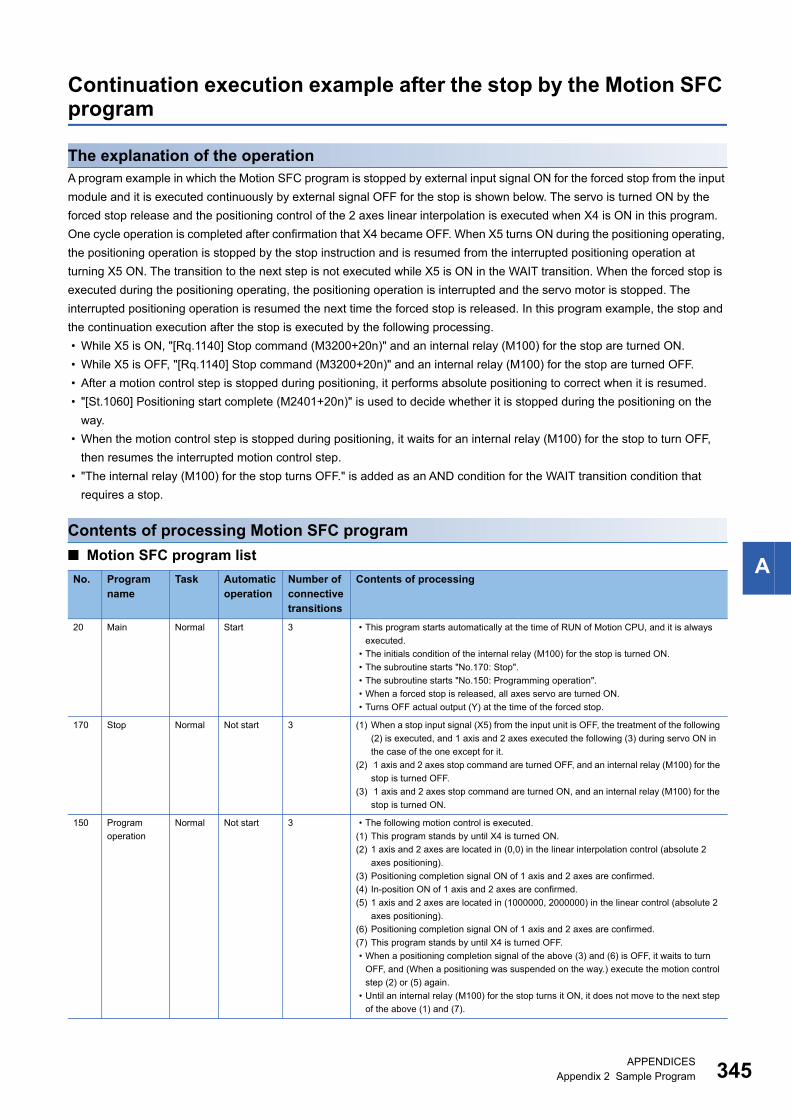
A
Continuation execution example after the stop by the Motion SFC program
The explanation of the operationA program example in which the Motion SFC program is stopped by external input signal ON for the forced stop from the input
module and it is executed continuously by external signal OFF for the stop is shown below. The servo is turned ON by the
forced stop release and the positioning control of the 2 axes linear interpolation is executed when X4 is ON in this program.
One cycle operation is completed after confirmation that X4 became OFF. When X5 turns ON during the positioning operating,
the positioning operation is stopped by the stop instruction and is resumed from the interrupted positioning operation at
turning X5 ON. The transition to the next step is not executed while X5 is ON in the WAIT transition. When the forced stop is
executed during the positioning operating, the positioning operation is interrupted and the servo motor is stopped. The
interrupted positioning operation is resumed the next time the forced stop is released. In this program example, the stop and
the continuation execution after the stop is executed by the following processing.
• While X5 is ON, "[Rq.1140] Stop command (M3200+20n)" and an internal relay (M100) for the stop are turned ON.
• While X5 is OFF, "[Rq.1140] Stop command (M3200+20n)" and an internal relay (M100) for the stop are turned OFF.
• After a motion control step is stopped during positioning, it performs absolute positioning to correct when it is resumed.
• "[St.1060] Positioning start complete (M2401+20n)" is used to decide whether it is stopped during the positioning on the
way.
• When the motion control step is stopped during positioning, it waits for an internal relay (M100) for the stop to turn OFF,
then resumes the interrupted motion control step.
• "The internal relay (M100) for the stop turns OFF." is added as an AND condition for the WAIT transition condition that
requires a stop.
Contents of processing Motion SFC program
■ Motion SFC program list
No. Program name
Task Automatic operation
Number of connective transitions
Contents of processing
20 Main Normal Start 3 • This program starts automatically at the time of RUN of Motion CPU, and it is always
executed.
• The initials condition of the internal relay (M100) for the stop is turned ON.
• The subroutine starts "No.170: Stop".
• The subroutine starts "No.150: Programming operation".
• When a forced stop is released, all axes servo are turned ON.
• Turns OFF actual output (Y) at the time of the forced stop.
170 Stop Normal Not start 3 (1) When a stop input signal (X5) from the input unit is OFF, the treatment of the following
(2) is executed, and 1 axis and 2 axes executed the following (3) during servo ON in
the case of the one except for it.
(2) 1 axis and 2 axes stop command are turned OFF, and an internal relay (M100) for the
stop is turned OFF.
(3) 1 axis and 2 axes stop command are turned ON, and an internal relay (M100) for the
stop is turned ON.
150 Program
operation
Normal Not start 3 • The following motion control is executed.
(1) This program stands by until X4 is turned ON.
(2) 1 axis and 2 axes are located in (0,0) in the linear interpolation control (absolute 2
axes positioning).
(3) Positioning completion signal ON of 1 axis and 2 axes are confirmed.
(4) In-position ON of 1 axis and 2 axes are confirmed.
(5) 1 axis and 2 axes are located in (1000000, 2000000) in the linear control (absolute 2
axes positioning).
(6) Positioning completion signal ON of 1 axis and 2 axes are confirmed.
(7) This program stands by until X4 is turned OFF.
• When a positioning completion signal of the above (3) and (6) is OFF, it waits to turn
OFF, and (When a positioning was suspended on the way.) execute the motion control
step (2) or (5) again.
• Until an internal relay (M100) for the stop turns it ON, it does not move to the next step
of the above (1) and (7).
APPENDICESAppendix 2 Sample Program 345

34
■ No.20: Main
■ No.170: Stop
Stop
Programming operation
[F20]SET M100 //Stop ON (Initials set)
Main
[G20]SM502 //Did you release a forced//stop?
[F110]SET M2042//All axes servo ON command// is ON
[F25]DOUT Y10,H0000 //Y10 to Y1F//(16 points)OFF
[G21]!SM502//Did you turn on forced//stop?
P0
P0
The subroutine starts "170: stop" and"150: Programming operation".
When a forced stop is released, all axisservo on command are turned on.
"Real output (Y)" is turned off at thetime of the forced stop.*: A subroutine during the start is made to stop if necessary.*: Actual output is turned off if necessary.*: The occurrence detection of servo error and so on is added to the stop condition with the forced stop if necessary.
The internal relay (M100) for the stopturn on.
The subroutine that motion control wasexecuted at the time of the forced stopdid not stop and which started it for awhile goes on, and it is executed bythis sample program.Motion control is stopped after servoOFF is detected at the time of theforced stop in the inside of thesubroutine.Resuming of the motion control isexecuted after all the axis servo ONcommand were turned on in thisprogram and the detection of servo ONwas done on the subroutine side whena forced stop is released.
[F170]//A stop is being released stop, status.RST M3200 //1 axis stop command OFFRST M3220 //2 axes stop command OFFRST M100 //Stop OFF
P0
P0
[G170]//Did you release a stop?// (Did a thing during servo ON and X5//turn off 1 axis and 2 axes?)M2415*M2435*!X5
[F171]//The stop is being turned on, status.SET M100 //Stop ONSET M3200 //1 axis stop command ONSET M3220 //2 axes stop command ON
Stop
When servo ON and the outside inputsignal (X5) for the stop are OFF, 1 axis,2 axis stop command are turned off,and 1 axis, 2 axis continue motioncontrol by turning off an internal relay(M100) for the stop.It is made to turn on 1 axis, 2 axis stopcommand, and motion control is madeto stop by turning on an internal relay(M100) for the stop, too, when eitheraxis turns off servo or when X5 turns iton.
6APPENDICESAppendix 2 Sample Program

A
■ No.150: Programming operation
P10
P20
P0
Programming operation
P0
[G151]//Did you turn on X4, and turn//off a stop?X4*!M100
[K150:Real]1 ABS-2 Axis 1, 0 pulse Axis 2, 0 pulse Vector speed 500000 pulse/s
[G200]//Did 1 axis and 2 axes execute//positioning completion?M2401*M2421
[F150]#0L=1000000//1 axis positioning//address set#2L=2000000//2 axes positioning//address set#4L=500000//Positioning speed set
[G154]//Did you turn on 1 axis and 2 axes//in-position signal?M2402*M2422
[G200]//Did 1 axis and 2 axes execute//positioning completion?M2401*M2421
[G156]//Did you turn on X4, and turn//off a stop?!X4*!M100
[G202]!M100 //Did you turn off a stop?
P10
[K151:Real]1 ABS-2 Axis 1, # 0 pulse Axis 2, # 2 pulse Vector Speed # 4 pulse/s
The motion control stepexecuted absolutepositioning to applicationwith it when to start againafter it stops on the way.
This program is judgedwhether it was stopped byusing the location completesignal during the locationon the way.This program is made toexecute the motion controlstep of again after internalrelay (M100) of the stopwaits to turn it off whenpositioning completion isnot turned on after themotion control is executed.
This program is judgedwhether it was stopped byusing the location completesignal during the locationon the way.It is made to execute themotion control step of againafter internal relay (M100)of the stop waits to turn itoff when positioningcompletion is not turned onafter the motion control isexecuted.[G202]
!M100 //Did you turn off a stop?
P20
WAIT transition whichwants to stop substitutes"The internal relay (M100)for the stop turns off." forthe AND status.
This program substitutes"The internal relay (M100)for the stop turns off." intothe AND status in WAITtransition which wants it tostop.
The motion control stepexecuted absolutepositioning to applicationwith it when to start againafter it stops on the way.
APPENDICESAppendix 2 Sample Program 347

348
REVISIONS* The manual number is given on the bottom left of the back cover
Japanese manual number: IB-0300238-L
2014 MITSUBISHI ELECTRIC CORPORATION
Revision date *Manual number Description
June 2014 IB(NA)-0300239-A First edition
March 2015 IB(NA)-0300239-B ■Added functions
MOTION DEDICATED PLC INSTRUCTION (M(P)CHGA, M(P)CHGAS, M(P)CHGV, M(P)CHGVS,
M(P)CHGT, M(P)BITWR/D(P)BITWR), Add-on Dedicated Function (MCFUN), Expansion of the number of
connections for vision system
■Added or modified parts
SAFETY PRECAUTIONS, RELEVANT MANUALS, TERMS, Section 1.1, 2.2, 2.3, 4.5, 4.14, 4.16, 4.17,
4.18, 4.19, 7.1, 7.1.2, Appendix 1
June 2015 IB(NA)-0300239-C ■Added or modified parts
TERMS, Section 2.2
February 2016 IB(NA)-0300239-D ■Added models
R64MTCPU
■Added functions
Motion dedicated function (MCNST)
■Added or modified parts
SAFETY PRECAUTIONS, INTRODUCTION, RELEVANT MANUALS, TERMS, MANUAL PAGE
ORGANIZATION, Section 1.1, 1.2, 2.2, 2.3, 4.2, 4.4, 4.15, 4.16, 4.19, 6.4, 6.5, 6.7, 6.8, 6.9, 7.1, 7.2,
Appendix 1, Appendix 2, Appendix 3, WARRANTY
June 2016 IB(NA)-0300239-E ■Added or modified parts
SAFETY PRECAUTIONS, INTRODUCTION, Section 4.1, 4.2, 4.5, 4.15, 4.16, 6.10
■Deleted parts
Appendix 3
September 2016 IB(NA)-0300239-F ■Added functions
Motion dedicated PLC instruction (M(P).MCNST/D(P).MCNST)
■Added or modified parts
TERMS, Section 1.1, 1.2, 2.2, 2.3, 3.1, 3.9, 3.10, 4.15, 4.16, 4.19, Appendix 1
December 2016 IB(NA)-0300239-G ■Added or modified parts
SAFETY PRECAUTIONS, Section 1.1, 2.2, 2.3, 3.2, 3.4, 3.5, 4.15, 4.19, Appendix 1, Appendix 2
December 2017 IB(NA)-0300239-H ■Added or modified parts
SAFETY PRECAUTIONS, RELEVANT MANUALS, MANUAL PAGE ORGANIZATION
June 2018 IB(NA)-0300239-J ■Added or modified parts
SAFETY PRECAUTIONS, Section 4.16
December 2018 IB(NA)-0300239-K ■Added or modified parts
SAFETY PRECAUTIONS, Section 4.5
February 2020 IB(NA)-0300239-L ■Added or modified parts
Section 2.2, 4.2, Appendix 2
This manual confers no industrial property rights of any other kind, nor does it confer any patent licenses. Mitsubishi Electric Corporation cannot be held
responsible for any problems involving industrial property rights which may occur as a result of using the contents noted in this manual.

349
WARRANTY
Please confirm the following product warranty details before using this product.
1. Gratis Warranty Term and Gratis Warranty RangeIf any faults or defects (hereinafter "Failure") found to be the responsibility of Mitsubishi occurs during use of the product within the gratis warranty term, the product shall be repaired at no cost via the sales representative or Mitsubishi Service Company.However, if repairs are required onsite at domestic or overseas location, expenses to send an engineer will be solely at the customer's discretion. Mitsubishi shall not be held responsible for any re-commissioning, maintenance, or testing on-site that involves replacement of the failed module.[Gratis Warranty Term]The gratis warranty term of the product shall be for one year after the date of purchase or delivery to a designated place.Note that after manufacture and shipment from Mitsubishi, the maximum distribution period shall be six (6) months, and the longest gratis warranty term after manufacturing shall be eighteen (18) months. The gratis warranty term of repair parts shall not exceed the gratis warranty term before repairs.[Gratis Warranty Range](1) The range shall be limited to normal use within the usage state, usage methods and usage environment, etc., which
follow the conditions and precautions, etc., given in the instruction manual, user's manual and caution labels on the product.
(2) Even within the gratis warranty term, repairs shall be charged for in the following cases.1. Failure occurring from inappropriate storage or handling, carelessness or negligence by the user. Failure caused
by the user's hardware or software design.2. Failure caused by unapproved modifications, etc., to the product by the user.3. When the Mitsubishi product is assembled into a user's device, Failure that could have been avoided if functions
or structures, judged as necessary in the legal safety measures the user's device is subject to or as necessary by industry standards, had been provided.
4. Failure that could have been avoided if consumable parts (battery, backlight, fuse, etc.) designated in the instruction manual had been correctly serviced or replaced.
5. Failure caused by external irresistible forces such as fires or abnormal voltages, and Failure caused by force majeure such as earthquakes, lightning, wind and water damage.
6. Failure caused by reasons unpredictable by scientific technology standards at time of shipment from Mitsubishi.7. Any other failure found not to be the responsibility of Mitsubishi or that admitted not to be so by the user.
2. Onerous repair term after discontinuation of production(1) Mitsubishi shall accept onerous product repairs for seven (7) years after production of the product is discontinued.
Discontinuation of production shall be notified with Mitsubishi Technical Bulletins, etc.(2) Product supply (including repair parts) is not available after production is discontinued.
3. Overseas serviceOverseas, repairs shall be accepted by Mitsubishi's local overseas FA Center. Note that the repair conditions at each FA Center may differ.
4. Exclusion of loss in opportunity and secondary loss from warranty liabilityRegardless of the gratis warranty term, Mitsubishi shall not be liable for compensation to:(1) Damages caused by any cause found not to be the responsibility of Mitsubishi.(2) Loss in opportunity, lost profits incurred to the user by Failures of Mitsubishi products.(3) Special damages and secondary damages whether foreseeable or not, compensation for accidents, and
compensation for damages to products other than Mitsubishi products.(4) Replacement by the user, maintenance of on-site equipment, start-up test run and other tasks.
5. Changes in product specificationsThe specifications given in the catalogs, manuals or technical documents are subject to change without prior notice.

350
TRADEMARKSMicrosoft, Microsoft Access, Excel, SQL Server, Visual Basic, Visual C++, Visual Studio, Windows, Windows NT, Windows
Server, Windows Vista, and Windows XP are either registered trademarks or trademarks of Microsoft Corporation in the
United States and/or other countries.
The company names, system names and product names mentioned in this manual are either registered trademarks or
trademarks of their respective companies.
In some cases, trademark symbols such as '' or '' are not specified in this manual.
IB(NA)-0300239-L


IB(NA)-0300239-L(2002)MEE
MODEL: RMT-P-PRG-E
MODEL CODE: 1XB006
Specifications subject to change without notice.
When exported from Japan, this manual does not require application to theMinistry of Economy, Trade and Industry for service transaction permission.
HEAD OFFICE : TOKYO BUILDING, 2-7-3 MARUNOUCHI, CHIYODA-KU, TOKYO 100-8310, JAPANNAGOYA WORKS : 1-14 , YADA-MINAMI 5-CHOME , HIGASHI-KU, NAGOYA , JAPAN