melsoft mx opc server ua version 3 operating …suport.siriustrading.ro/02.docarh/09.ms/03.net/04.mx...
TRANSCRIPT

MELSOFT MX OPC Server UA Version 3 Operating Manual
-SW3DND-OPCUAS-E

1
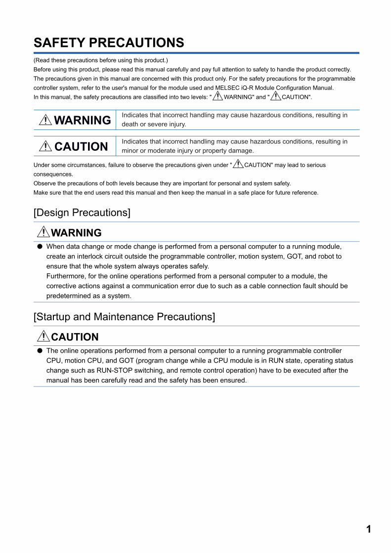
SAFETY PRECAUTIONS(Read these precautions before using this product.)
Before using this product, please read this manual carefully and pay full attention to safety to handle the product correctly.
The precautions given in this manual are concerned with this product only. For the safety precautions for the programmable
controller system, refer to the user's manual for the module used and MELSEC iQ-R Module Configuration Manual.
In this manual, the safety precautions are classified into two levels: " WARNING" and " CAUTION".
Under some circumstances, failure to observe the precautions given under " CAUTION" may lead to serious
consequences.
Observe the precautions of both levels because they are important for personal and system safety.
Make sure that the end users read this manual and then keep the manual in a safe place for future reference.
[Design Precautions]
[Startup and Maintenance Precautions]
WARNING● When data change or mode change is performed from a personal computer to a running module,
create an interlock circuit outside the programmable controller, motion system, GOT, and robot to
ensure that the whole system always operates safely.
Furthermore, for the online operations performed from a personal computer to a module, the
corrective actions against a communication error due to such as a cable connection fault should be
predetermined as a system.
CAUTION● The online operations performed from a personal computer to a running programmable controller
CPU, motion CPU, and GOT (program change while a CPU module is in RUN state, operating status
change such as RUN-STOP switching, and remote control operation) have to be executed after the
manual has been carefully read and the safety has been ensured.
WARNING Indicates that incorrect handling may cause hazardous conditions, resulting in death or severe injury.
CAUTION Indicates that incorrect handling may cause hazardous conditions, resulting in minor or moderate injury or property damage.

2
CONDITIONS OF USE FOR THE PRODUCT
(1) Mitsubishi programmable controller ("the PRODUCT") shall be used in conditions;i) where any problem, fault or failure occurring in the PRODUCT, if any, shall not lead to any major or serious accident; and ii) where the backup and fail-safe function are systematically or automatically provided outside of the PRODUCT for the case of any problem, fault or failure occurring in the PRODUCT.
(2) The PRODUCT has been designed and manufactured for the purpose of being used in general industries.MITSUBISHI SHALL HAVE NO RESPONSIBILITY OR LIABILITY (INCLUDING, BUT NOT LIMITED TO ANY AND ALL RESPONSIBILITY OR LIABILITY BASED ON CONTRACT, WARRANTY, TORT, PRODUCT LIABILITY) FOR ANY INJURY OR DEATH TO PERSONS OR LOSS OR DAMAGE TO PROPERTY CAUSED BY the PRODUCT THAT ARE OPERATED OR USED IN APPLICATION NOT INTENDED OR EXCLUDED BY INSTRUCTIONS, PRECAUTIONS, OR WARNING CONTAINED IN MITSUBISHI'S USER, INSTRUCTION AND/OR SAFETY MANUALS, TECHNICAL BULLETINS AND GUIDELINES FOR the PRODUCT. ("Prohibited Application")Prohibited Applications include, but not limited to, the use of the PRODUCT in;• Nuclear Power Plants and any other power plants operated by Power companies, and/or any other cases in which the
public could be affected if any problem or fault occurs in the PRODUCT.• Railway companies or Public service purposes, and/or any other cases in which establishment of a special quality
assurance system is required by the Purchaser or End User.• Aircraft or Aerospace, Medical applications, Train equipment, transport equipment such as Elevator and Escalator,
Incineration and Fuel devices, Vehicles, Manned transportation, Equipment for Recreation and Amusement, and Safety devices, handling of Nuclear or Hazardous Materials or Chemicals, Mining and Drilling, and/or other applications where there is a significant risk of injury to the public or property.
Notwithstanding the above, restrictions Mitsubishi may in its sole discretion, authorize use of the PRODUCT in one or more of the Prohibited Applications, provided that the usage of the PRODUCT is limited only for the specific applications agreed to by Mitsubishi and provided further that no special quality assurance or fail-safe, redundant or other safety features which exceed the general specifications of the PRODUCTs are required. For details, please contact the Mitsubishi representative in your region.

3
INTRODUCTIONThank you for purchasing the engineering software, MELSOFT series.
This manual describes the functions required when using MELSOFT MX OPC Server UA.
Before using this product, please read this manual carefully, and develop familiarity with the functions and performance of
MELSOFT MX OPC Server UA Configuration Tool to handle the product correctly.

4
CONTENTSSAFETY PRECAUTIONS . . . . . . . . . . . . . . . . . . . . . . . . . . . . . . . . . . . . . . . . . . . . . . . . . . . . . . . . . . . . . . . . . . . .1
CONDITIONS OF USE FOR THE PRODUCT . . . . . . . . . . . . . . . . . . . . . . . . . . . . . . . . . . . . . . . . . . . . . . . . . . . .2
INTRODUCTION. . . . . . . . . . . . . . . . . . . . . . . . . . . . . . . . . . . . . . . . . . . . . . . . . . . . . . . . . . . . . . . . . . . . . . . . . . .3
RELEVANT MANUALS . . . . . . . . . . . . . . . . . . . . . . . . . . . . . . . . . . . . . . . . . . . . . . . . . . . . . . . . . . . . . . . . . . . . . .8
TERMS . . . . . . . . . . . . . . . . . . . . . . . . . . . . . . . . . . . . . . . . . . . . . . . . . . . . . . . . . . . . . . . . . . . . . . . . . . . . . . . . . .8
PART 1 FUNDAMENTALS OF MX OPC Server UA
CHAPTER 1 FEATURES OF MX OPC Server UA 12
CHAPTER 2 SPECIFICATIONS OF MX OPC Server UA 14
CHAPTER 3 FUNCTION LIST OF MX OPC UA Server 17
CHAPTER 4 FUNCTION LIST OF CONFIGURATION TOOL 19
CHAPTER 5 OPERATING PROCEDURE (FLOW) 21
PART 2 SERVER FUNCTIONS
CHAPTER 6 START AND END 24
CHAPTER 7 SECURITY OF MX OPC Server UA 26
7.1 Certificate Management . . . . . . . . . . . . . . . . . . . . . . . . . . . . . . . . . . . . . . . . . . . . . . . . . . . . . . . . . . . . . . . . . . 26
7.2 Client Certificates . . . . . . . . . . . . . . . . . . . . . . . . . . . . . . . . . . . . . . . . . . . . . . . . . . . . . . . . . . . . . . . . . . . . . . . 27
7.3 Server Certificates. . . . . . . . . . . . . . . . . . . . . . . . . . . . . . . . . . . . . . . . . . . . . . . . . . . . . . . . . . . . . . . . . . . . . . . 28
7.4 Security Setting for MX OPC UA Server . . . . . . . . . . . . . . . . . . . . . . . . . . . . . . . . . . . . . . . . . . . . . . . . . . . . . 29
CHAPTER 8 SYSTEM CONFIGURATION 30
CHAPTER 9 COMMUNICATION FUNCTION 32
9.1 Communication with Devices and Tags . . . . . . . . . . . . . . . . . . . . . . . . . . . . . . . . . . . . . . . . . . . . . . . . . . . . . 32
Enabling communication with devices. . . . . . . . . . . . . . . . . . . . . . . . . . . . . . . . . . . . . . . . . . . . . . . . . . . . . . . . . 32
Enabling communication with tags . . . . . . . . . . . . . . . . . . . . . . . . . . . . . . . . . . . . . . . . . . . . . . . . . . . . . . . . . . . 33
9.2 Starting or Stopping Polling. . . . . . . . . . . . . . . . . . . . . . . . . . . . . . . . . . . . . . . . . . . . . . . . . . . . . . . . . . . . . . . 34
Start . . . . . . . . . . . . . . . . . . . . . . . . . . . . . . . . . . . . . . . . . . . . . . . . . . . . . . . . . . . . . . . . . . . . . . . . . . . . . . . . . . . 34
Stop . . . . . . . . . . . . . . . . . . . . . . . . . . . . . . . . . . . . . . . . . . . . . . . . . . . . . . . . . . . . . . . . . . . . . . . . . . . . . . . . . . . 34
PART 3 CONFIGURATION TOOL FUNCTIONS
CHAPTER 10 SCREEN CONFIGURATION AND BASIC OPERATIONS 38
10.1 Start and End . . . . . . . . . . . . . . . . . . . . . . . . . . . . . . . . . . . . . . . . . . . . . . . . . . . . . . . . . . . . . . . . . . . . . . . . . . . 38
10.2 Screen Configuration . . . . . . . . . . . . . . . . . . . . . . . . . . . . . . . . . . . . . . . . . . . . . . . . . . . . . . . . . . . . . . . . . . . . 39
Main frame. . . . . . . . . . . . . . . . . . . . . . . . . . . . . . . . . . . . . . . . . . . . . . . . . . . . . . . . . . . . . . . . . . . . . . . . . . . . . . 39
10.3 Menu List . . . . . . . . . . . . . . . . . . . . . . . . . . . . . . . . . . . . . . . . . . . . . . . . . . . . . . . . . . . . . . . . . . . . . . . . . . . . . . 40
10.4 Cut, Copy, or Paste . . . . . . . . . . . . . . . . . . . . . . . . . . . . . . . . . . . . . . . . . . . . . . . . . . . . . . . . . . . . . . . . . . . . . . 43

5
CO
NT
EN
TS
10.5 Option Settings . . . . . . . . . . . . . . . . . . . . . . . . . . . . . . . . . . . . . . . . . . . . . . . . . . . . . . . . . . . . . . . . . . . . . . . . . 44
General setting . . . . . . . . . . . . . . . . . . . . . . . . . . . . . . . . . . . . . . . . . . . . . . . . . . . . . . . . . . . . . . . . . . . . . . . . . . 45
Logging . . . . . . . . . . . . . . . . . . . . . . . . . . . . . . . . . . . . . . . . . . . . . . . . . . . . . . . . . . . . . . . . . . . . . . . . . . . . . . . . 46
Server setting . . . . . . . . . . . . . . . . . . . . . . . . . . . . . . . . . . . . . . . . . . . . . . . . . . . . . . . . . . . . . . . . . . . . . . . . . . . 47
Firewall . . . . . . . . . . . . . . . . . . . . . . . . . . . . . . . . . . . . . . . . . . . . . . . . . . . . . . . . . . . . . . . . . . . . . . . . . . . . . . . . 52
10.6 Learning Operation Methods of Configuration Tool . . . . . . . . . . . . . . . . . . . . . . . . . . . . . . . . . . . . . . . . . . . 54
Displaying Help . . . . . . . . . . . . . . . . . . . . . . . . . . . . . . . . . . . . . . . . . . . . . . . . . . . . . . . . . . . . . . . . . . . . . . . . . . 54
Checking the version of Configuration Tool . . . . . . . . . . . . . . . . . . . . . . . . . . . . . . . . . . . . . . . . . . . . . . . . . . . . . 54
CHAPTER 11 SERVER CONNECTION 55
11.1 Configuration File Management. . . . . . . . . . . . . . . . . . . . . . . . . . . . . . . . . . . . . . . . . . . . . . . . . . . . . . . . . . . . 55
Version and setting file extension . . . . . . . . . . . . . . . . . . . . . . . . . . . . . . . . . . . . . . . . . . . . . . . . . . . . . . . . . . . . 55
File management method and the status of Configuration Tool . . . . . . . . . . . . . . . . . . . . . . . . . . . . . . . . . . . . . 55
Creating configuration files . . . . . . . . . . . . . . . . . . . . . . . . . . . . . . . . . . . . . . . . . . . . . . . . . . . . . . . . . . . . . . . . . 56
Opening configuration files . . . . . . . . . . . . . . . . . . . . . . . . . . . . . . . . . . . . . . . . . . . . . . . . . . . . . . . . . . . . . . . . . 57
Saving configuration files. . . . . . . . . . . . . . . . . . . . . . . . . . . . . . . . . . . . . . . . . . . . . . . . . . . . . . . . . . . . . . . . . . . 58
Deleting configuration files . . . . . . . . . . . . . . . . . . . . . . . . . . . . . . . . . . . . . . . . . . . . . . . . . . . . . . . . . . . . . . . . . 60
11.2 Connection Setting with Server . . . . . . . . . . . . . . . . . . . . . . . . . . . . . . . . . . . . . . . . . . . . . . . . . . . . . . . . . . . . 61
Setting a connection with Server . . . . . . . . . . . . . . . . . . . . . . . . . . . . . . . . . . . . . . . . . . . . . . . . . . . . . . . . . . . . . 61
Status of a connected server. . . . . . . . . . . . . . . . . . . . . . . . . . . . . . . . . . . . . . . . . . . . . . . . . . . . . . . . . . . . . . . . 62
CHAPTER 12 DEVICE SETTING 63
12.1 Address Space (Access Target Device) Setting . . . . . . . . . . . . . . . . . . . . . . . . . . . . . . . . . . . . . . . . . . . . . . . 63
Newly adding or editing MX devices . . . . . . . . . . . . . . . . . . . . . . . . . . . . . . . . . . . . . . . . . . . . . . . . . . . . . . . . . . 63
Newly adding or editing Modbus devices . . . . . . . . . . . . . . . . . . . . . . . . . . . . . . . . . . . . . . . . . . . . . . . . . . . . . . 70
Deleting MX devices or Modbus devices. . . . . . . . . . . . . . . . . . . . . . . . . . . . . . . . . . . . . . . . . . . . . . . . . . . . . . . 76
12.2 Setting Connection Destinations . . . . . . . . . . . . . . . . . . . . . . . . . . . . . . . . . . . . . . . . . . . . . . . . . . . . . . . . . . . 77
Connection destination setting for an MX device . . . . . . . . . . . . . . . . . . . . . . . . . . . . . . . . . . . . . . . . . . . . . . . . 77
Communication setting wizard screen operation. . . . . . . . . . . . . . . . . . . . . . . . . . . . . . . . . . . . . . . . . . . . . . . . . 79
Configuring the settings on the personal computer side . . . . . . . . . . . . . . . . . . . . . . . . . . . . . . . . . . . . . . . . . . . 83
Configuring the settings on the connection destination device side . . . . . . . . . . . . . . . . . . . . . . . . . . . . . . . . . . 95
Network station number type setting . . . . . . . . . . . . . . . . . . . . . . . . . . . . . . . . . . . . . . . . . . . . . . . . . . . . . . . . . 108
Station number type - other station setting . . . . . . . . . . . . . . . . . . . . . . . . . . . . . . . . . . . . . . . . . . . . . . . . . . . . 123
Entering a comment . . . . . . . . . . . . . . . . . . . . . . . . . . . . . . . . . . . . . . . . . . . . . . . . . . . . . . . . . . . . . . . . . . . . . 126
Multiple CPU system . . . . . . . . . . . . . . . . . . . . . . . . . . . . . . . . . . . . . . . . . . . . . . . . . . . . . . . . . . . . . . . . . . . . . 127
Restrictions on C Controller module connection . . . . . . . . . . . . . . . . . . . . . . . . . . . . . . . . . . . . . . . . . . . . . . . . 128
CHAPTER 13 TAG SETTING AND MONITORING 129
13.1 Address Space (Tag) Setting . . . . . . . . . . . . . . . . . . . . . . . . . . . . . . . . . . . . . . . . . . . . . . . . . . . . . . . . . . . . . 129
Newly adding or editing MX device tags . . . . . . . . . . . . . . . . . . . . . . . . . . . . . . . . . . . . . . . . . . . . . . . . . . . . . . 129
Details of address specification . . . . . . . . . . . . . . . . . . . . . . . . . . . . . . . . . . . . . . . . . . . . . . . . . . . . . . . . . . . . . 137
Newly adding or editing Modbus device tags . . . . . . . . . . . . . . . . . . . . . . . . . . . . . . . . . . . . . . . . . . . . . . . . . . 138
Deleting tags . . . . . . . . . . . . . . . . . . . . . . . . . . . . . . . . . . . . . . . . . . . . . . . . . . . . . . . . . . . . . . . . . . . . . . . . . . . 142
13.2 Group . . . . . . . . . . . . . . . . . . . . . . . . . . . . . . . . . . . . . . . . . . . . . . . . . . . . . . . . . . . . . . . . . . . . . . . . . . . . . . . . 143
Newly adding or editing groups . . . . . . . . . . . . . . . . . . . . . . . . . . . . . . . . . . . . . . . . . . . . . . . . . . . . . . . . . . . . . 143
Deleting groups . . . . . . . . . . . . . . . . . . . . . . . . . . . . . . . . . . . . . . . . . . . . . . . . . . . . . . . . . . . . . . . . . . . . . . . . . 144
13.3 Structure Labels . . . . . . . . . . . . . . . . . . . . . . . . . . . . . . . . . . . . . . . . . . . . . . . . . . . . . . . . . . . . . . . . . . . . . . . 145
Newly adding or editing structure labels . . . . . . . . . . . . . . . . . . . . . . . . . . . . . . . . . . . . . . . . . . . . . . . . . . . . . . 145
Structure label definition screen setting. . . . . . . . . . . . . . . . . . . . . . . . . . . . . . . . . . . . . . . . . . . . . . . . . . . . . . . 146
Deleting structure labels . . . . . . . . . . . . . . . . . . . . . . . . . . . . . . . . . . . . . . . . . . . . . . . . . . . . . . . . . . . . . . . . . . 153

6
13.4 Monitoring . . . . . . . . . . . . . . . . . . . . . . . . . . . . . . . . . . . . . . . . . . . . . . . . . . . . . . . . . . . . . . . . . . . . . . . . . . . . 154
13.5 Writing Values to Tags . . . . . . . . . . . . . . . . . . . . . . . . . . . . . . . . . . . . . . . . . . . . . . . . . . . . . . . . . . . . . . . . . . 155
CHAPTER 14 STATISTICS INFORMATION DISPLAY 156
14.1 Display Method . . . . . . . . . . . . . . . . . . . . . . . . . . . . . . . . . . . . . . . . . . . . . . . . . . . . . . . . . . . . . . . . . . . . . . . . 156
CHAPTER 15 VARIOUS DEFINITIONS (ALARM, CONVERSION, POLLING, STRUCTURE) 158
15.1 Setting Alarm Definitions . . . . . . . . . . . . . . . . . . . . . . . . . . . . . . . . . . . . . . . . . . . . . . . . . . . . . . . . . . . . . . . . 158
Newly adding or editing limit alarm definitions. . . . . . . . . . . . . . . . . . . . . . . . . . . . . . . . . . . . . . . . . . . . . . . . . . 158
Newly adding or editing digital alarm definitions . . . . . . . . . . . . . . . . . . . . . . . . . . . . . . . . . . . . . . . . . . . . . . . . 161
Associating alarm definitions with tags . . . . . . . . . . . . . . . . . . . . . . . . . . . . . . . . . . . . . . . . . . . . . . . . . . . . . . . 163
Deleting alarm definitions . . . . . . . . . . . . . . . . . . . . . . . . . . . . . . . . . . . . . . . . . . . . . . . . . . . . . . . . . . . . . . . . . 163
15.2 Setting Conversion Definitions . . . . . . . . . . . . . . . . . . . . . . . . . . . . . . . . . . . . . . . . . . . . . . . . . . . . . . . . . . . 164
Newly adding or editing conversion definitions . . . . . . . . . . . . . . . . . . . . . . . . . . . . . . . . . . . . . . . . . . . . . . . . . 164
Associating conversion definitions with tags . . . . . . . . . . . . . . . . . . . . . . . . . . . . . . . . . . . . . . . . . . . . . . . . . . . 165
Deleting conversion definitions . . . . . . . . . . . . . . . . . . . . . . . . . . . . . . . . . . . . . . . . . . . . . . . . . . . . . . . . . . . . . 165
15.3 Setting Polling Definitions . . . . . . . . . . . . . . . . . . . . . . . . . . . . . . . . . . . . . . . . . . . . . . . . . . . . . . . . . . . . . . . 166
Newly adding or editing polling definitions. . . . . . . . . . . . . . . . . . . . . . . . . . . . . . . . . . . . . . . . . . . . . . . . . . . . . 166
Associating polling definitions with tags . . . . . . . . . . . . . . . . . . . . . . . . . . . . . . . . . . . . . . . . . . . . . . . . . . . . . . 167
Deleting polling definitions. . . . . . . . . . . . . . . . . . . . . . . . . . . . . . . . . . . . . . . . . . . . . . . . . . . . . . . . . . . . . . . . . 167
15.4 Setting Structure Definitions . . . . . . . . . . . . . . . . . . . . . . . . . . . . . . . . . . . . . . . . . . . . . . . . . . . . . . . . . . . . . 168
Newly adding or editing structure definitions . . . . . . . . . . . . . . . . . . . . . . . . . . . . . . . . . . . . . . . . . . . . . . . . . . . 168
Deleting structure definitions . . . . . . . . . . . . . . . . . . . . . . . . . . . . . . . . . . . . . . . . . . . . . . . . . . . . . . . . . . . . . . . 170
CHAPTER 16 SIMULATION 171
16.1 Setting Simulation Signal Definitions . . . . . . . . . . . . . . . . . . . . . . . . . . . . . . . . . . . . . . . . . . . . . . . . . . . . . . 171
Newly adding or editing simulation signal definitions . . . . . . . . . . . . . . . . . . . . . . . . . . . . . . . . . . . . . . . . . . . . 171
Associating simulation signal definitions with tags . . . . . . . . . . . . . . . . . . . . . . . . . . . . . . . . . . . . . . . . . . . . . . 173
Deleting simulation signal definitions. . . . . . . . . . . . . . . . . . . . . . . . . . . . . . . . . . . . . . . . . . . . . . . . . . . . . . . . . 173
CHAPTER 17 IMPORT OF EcoWebServer III CONFIGURATION FILES 174
17.1 Automatic Generation of EcoWebServer III Tags . . . . . . . . . . . . . . . . . . . . . . . . . . . . . . . . . . . . . . . . . . . . . 174
17.2 Settings for Connecting to EcoWebServer III . . . . . . . . . . . . . . . . . . . . . . . . . . . . . . . . . . . . . . . . . . . . . . . . 179
17.3 Tags for Demand Measurement Point . . . . . . . . . . . . . . . . . . . . . . . . . . . . . . . . . . . . . . . . . . . . . . . . . . . . . . 180
CHAPTER 18 IMPORT OF CSP+ (MACHINE PROFILE) 181
18.1 Automatic Generation of Tags Using CSP+ (Machine Profile) . . . . . . . . . . . . . . . . . . . . . . . . . . . . . . . . . . 181
18.2 Import CSP+ (Machine Profile) Screen . . . . . . . . . . . . . . . . . . . . . . . . . . . . . . . . . . . . . . . . . . . . . . . . . . . . . 184
CHAPTER 19 IMPORT OF MX OPC Server DA SETTINGS 185
19.1 Using Server Settings of MX OPC Server DA . . . . . . . . . . . . . . . . . . . . . . . . . . . . . . . . . . . . . . . . . . . . . . . . 185
PART 4 TROUBLESHOOTING
CHAPTER 20 TROUBLESHOOTING 188

7
CO
NT
EN
TS
CHAPTER 21 ERROR CODES 190
21.1 Server Error Codes . . . . . . . . . . . . . . . . . . . . . . . . . . . . . . . . . . . . . . . . . . . . . . . . . . . . . . . . . . . . . . . . . . . . . 191
HRESULT error codes. . . . . . . . . . . . . . . . . . . . . . . . . . . . . . . . . . . . . . . . . . . . . . . . . . . . . . . . . . . . . . . . . . . . 191
Server error codes. . . . . . . . . . . . . . . . . . . . . . . . . . . . . . . . . . . . . . . . . . . . . . . . . . . . . . . . . . . . . . . . . . . . . . . 192
Error codes in a connection destination device . . . . . . . . . . . . . . . . . . . . . . . . . . . . . . . . . . . . . . . . . . . . . . . . . 216
APPENDIX 217
Appendix 1 Additions and Changes from Previous Version . . . . . . . . . . . . . . . . . . . . . . . . . . . . . . . . . . . . . . . . . 217
Appendix 2 Version Compatibility . . . . . . . . . . . . . . . . . . . . . . . . . . . . . . . . . . . . . . . . . . . . . . . . . . . . . . . . . . . . . . 218
Appendix 3 Differences between MX OPC Server UA and MX OPC DA . . . . . . . . . . . . . . . . . . . . . . . . . . . . . . . . 220
Appendix 4 Restart of Service . . . . . . . . . . . . . . . . . . . . . . . . . . . . . . . . . . . . . . . . . . . . . . . . . . . . . . . . . . . . . . . . . 221
Appendix 5 USB Driver Installation Procedure . . . . . . . . . . . . . . . . . . . . . . . . . . . . . . . . . . . . . . . . . . . . . . . . . . . . 222
INDEX 223
REVISIONS. . . . . . . . . . . . . . . . . . . . . . . . . . . . . . . . . . . . . . . . . . . . . . . . . . . . . . . . . . . . . . . . . . . . . . . . . . . . .225
TRADEMARKS . . . . . . . . . . . . . . . . . . . . . . . . . . . . . . . . . . . . . . . . . . . . . . . . . . . . . . . . . . . . . . . . . . . . . . . . . .226

8
RELEVANT MANUALS
e-Manual refers to the Mitsubishi Electric FA electronic book manuals that can be browsed using a dedicated
tool.
e-Manual has the following features:
• Required information can be cross-searched in multiple manuals.
• Other manuals can be accessed from the links in the manual.
• Hardware specifications of each part can be found from the product figures.
• Pages that users often browse can be bookmarked.
• Sample programs can be copied to an engineering tool.
TERMSUnless otherwise specified, this manual uses the following terms.
Manual name [manual number] Description Available form
MELSOFT MX OPC Server UA Version 3 Operating
Manual
[SH-081859ENG-A] (this manual)
Explains the system configurations, function descriptions, and
usages of a MELSOFT MX OPC Server UA.
e-Manual
Term Description
Address space Data that contains information of an access target device, a group, and a tag.
cfg The extension of a configuration file created in MX OPC Server UA Configuration Tool (version 2.04 or earlier).
cfg3 The extension of a configuration file created in MX OPC Server UA Configuration Tool (version 3.00 or later).
Clamping To set the upper limit value and the lower limit value, and control a value within that range.
Configuration Tool An abbreviation for MELSOFT MX OPC Server UA Configuration Tool.
CSP+ (machine profile) Data that stores information of devices.
Discovery server A server that manages endpoints of each MX OPC UA Server on a network.
EcoWebServer III Refers to Energy Saving Data Collecting Server.
Endpoint An OPC UA client application or MX OPC UA Server installed in a personal computer connected at the end of network.
Engineering tool A tool for setting, programming, debugging, and maintaining programmable controllers.
A generic term for GX Works2 and GX Works3.
FXCPU A generic term for FX3SCPU, FX3GCPU, FX3GCCPU, FX3GECPU, FX3UCPU, FX3UCCPU, FX5UCPU, and
FX5UCCPU.
GOT A generic term for Mitsubishi Graphic Operation Terminal GOT1000 series and GOT2000 series.
GX Works2 A generic product name for SWnDNC-GXW2 and SWnDND-GXW2. ('n' indicates its version.)
GX Works3 A generic product name for SWnDND-GXW3. ('n' indicates its version.)
LCPU A generic term for L02SCPU, L02SCPU-P, L02CPU, L02CPU-P, L06CPU, L06CPU-P, L26CPU, L26CPU-P, L26CPU-BT,
and L26CPU-PBT.
MELSOFT MX OPC Server UA
Configuration Tool
The setting part of MX OPC Server UA.
Modbus device A device connected by using the Modbus protocol.
Motion CPU A generic term for R Motions and Q Motions.
MX device A generic term for Mitsubishi FA devices (such as programmable controllers, NC devices) and MELSOFT simulator.
MX OPC Server UA A product name for SW3DND-OPCUAS.
MX OPC UA Server The communication part of MX OPC Server UA.
NCCPU A generic term for M850WCPU, M830WCPU, M850SCPU, M830SCPU, M80CPU, and M80WCPU.
OPC An acronym for OLE for Process Control.
An interoperability standard for the secure and reliable exchange of data in an industrial automation field and in other
industries.
OPC UA An acronym for OPC Unified Architecture.
Platform independent service-oriented architecture that integrates all the functionality of each OPC Classic specification
into an extensible framework.
Programmable controller CPU A generic term for RCPUs, FX5CPUs, QCPUs, LCPUs, and FXCPUs.
Q Motion A generic term for Q172CPU, Q173CPU, Q172HCPU, Q173HCPU, Q172DCPU, Q173DCPU, Q172DSCPU, and
Q173DSCPU.

9
QCPU A generic term for Q00JCPU, Q00UJCPU, Q00CPU, Q00UCPU, Q01CPU, Q01UCPU, Q02CPU, Q02HCPU,
Q02PHCPU, Q02UCPU, Q03UDCPU, Q03UDECPU, Q03UDVCPU, Q04UDHCPU, Q04UDEHCPU, Q04UDVCPU,
Q06HCPU, Q06PHCPU, Q06UDHCPU, Q06UDEHCPU, Q06UDVCPU, Q10UDHCPU, Q10UDEHCPU, Q12HCPU,
Q12PHCPU, Q12PRHCPU, Q13UDHCPU, Q13UDEHCPU, Q13UDVCPU, Q20UDHCPU, Q20UDEHCPU, Q25HCPU,
Q25PHCPU, Q25PRHCPU, Q26UDHCPU, Q26UDEHCPU, Q26UDVCPU, Q50UDEHCPU, and Q100UDEHCPU.
R Motion A generic term for R16MTCPU, R32MTCPU, and R64MTCPU.
R Safety A generic term for R08SFCPU, R16SFCPU, R32SFCPU, and R120SFCPU.
RCPU A generic term for R00CPU, R01CPU, R02CPU, R04CPU, R04ENCPU, R08CPU, R08PCPU, R08PSFCPU, R08ENCPU,
R16CPU, R16PCPU, R16ENCPU, R16PSFCPU, R32CPU, R32PCPU, R32ENCPU, R32PSFCPU, R120CPU,
R120PCPU, R120ENCPU, and R120PSFCPU.
Server An abbreviation for MX OPC UA Server.
Tag Information to access device data of the CPU module of the own station or a CPU module on a network from an OPC UA
client application.
Term Description

10
MEMO

11
PA
RT
1
PART 1 FUNDAMENTALS OF MX OPC Server UA
This part explains the overview of MX OPC Server UA.
1 FEATURES OF MX OPC Server UA
2 SPECIFICATIONS OF MX OPC Server UA
3 FUNCTION LIST OF MX OPC UA Server
4 FUNCTION LIST OF CONFIGURATION TOOL
5 OPERATING PROCEDURE (FLOW)
121 FEATURES OF MX OPC Server UA
1 FEATURES OF MX OPC Server UA
MX OPC Server UA consists of the following components:
• MX OPC UA Server
• MELSOFT MX OPC Server UA Configuration Tool
Features of MX OPC Server UAThe following shows the features of MX OPC Server UA:
■Connection with various SLMP-supported Mitsubishi FA devices is availableMX OPC Server UA employs Mitsubishi EZ socket for communication. This allows data communication among various
Mitsubishi FA devices such as programmable controllers, NC devices, and EcoWebServerIII.
■Connection with Mitsubishi simulator is availableMX OPC Server UA can be connected with a Mitsubishi MELSOFT simulator (programmable controller).
By using 3D simulator and MELSOFT simulator together, devices can be verified without having an actual system.
■Tag setting effort can be reducedBy reading CSP+ (machine profile) using Configuration Tool, tag information which is required for accessing device
information from an upper application can easily be set.

1 FEATURES OF MX OPC Server UA 13
1
MEMO
142 SPECIFICATIONS OF MX OPC Server UA
2 SPECIFICATIONS OF MX OPC Server UA
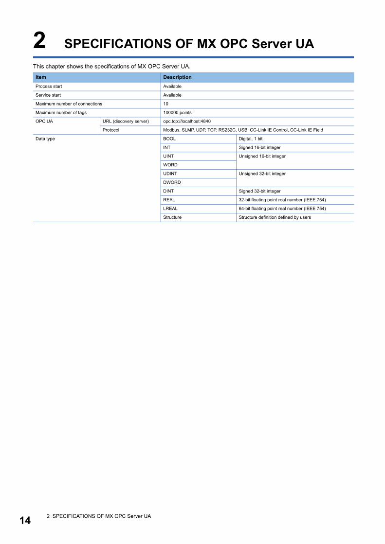
This chapter shows the specifications of MX OPC Server UA.
Item Description
Process start Available
Service start Available
Maximum number of connections 10
Maximum number of tags 100000 points
OPC UA URL (discovery server) opc.tcp://localhost:4840
Protocol Modbus, SLMP, UDP, TCP, RS232C, USB, CC-Link IE Control, CC-Link IE Field
Data type BOOL Digital, 1 bit
INT Signed 16-bit integer
UINT Unsigned 16-bit integer
WORD
UDINT Unsigned 32-bit integer
DWORD
DINT Signed 32-bit integer
REAL 32-bit floating point real number (IEEE 754)
LREAL 64-bit floating point real number (IEEE 754)
Structure Structure definition defined by users
2 SPECIFICATIONS OF MX OPC Server UA 15
2
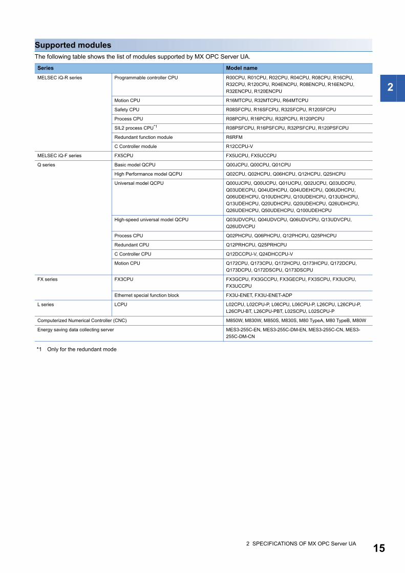
Supported modulesThe following table shows the list of modules supported by MX OPC Server UA.
*1 Only for the redundant mode
Series Model name
MELSEC iQ-R series Programmable controller CPU R00CPU, R01CPU, R02CPU, R04CPU, R08CPU, R16CPU,
R32CPU, R120CPU, R04ENCPU, R08ENCPU, R16ENCPU,
R32ENCPU, R120ENCPU
Motion CPU R16MTCPU, R32MTCPU, R64MTCPU
Safety CPU R08SFCPU, R16SFCPU, R32SFCPU, R120SFCPU
Process CPU R08PCPU, R16PCPU, R32PCPU, R120PCPU
SIL2 process CPU*1 R08PSFCPU, R16PSFCPU, R32PSFCPU, R120PSFCPU
Redundant function module R6RFM
C Controller module R12CCPU-V
MELSEC iQ-F series FX5CPU FX5UCPU, FX5UCCPU
Q series Basic model QCPU Q00JCPU, Q00CPU, Q01CPU
High Performance model QCPU Q02CPU, Q02HCPU, Q06HCPU, Q12HCPU, Q25HCPU
Universal model QCPU Q00UJCPU, Q00UCPU, Q01UCPU, Q02UCPU, Q03UDCPU,
Q03UDECPU, Q04UDHCPU, Q04UDEHCPU, Q06UDHCPU,
Q06UDEHCPU, Q10UDHCPU, Q10UDEHCPU, Q13UDHCPU,
Q13UDEHCPU, Q20UDHCPU, Q20UDEHCPU, Q26UDHCPU,
Q26UDEHCPU, Q50UDEHCPU, Q100UDEHCPU
High-speed universal model QCPU Q03UDVCPU, Q04UDVCPU, Q06UDVCPU, Q13UDVCPU,
Q26UDVCPU
Process CPU Q02PHCPU, Q06PHCPU, Q12PHCPU, Q25PHCPU
Redundant CPU Q12PRHCPU, Q25PRHCPU
C Controller CPU Q12DCCPU-V, Q24DHCCPU-V
Motion CPU Q172CPU, Q173CPU, Q172HCPU, Q173HCPU, Q172DCPU,
Q173DCPU, Q172DSCPU, Q173DSCPU
FX series FX3CPU FX3GCPU, FX3GCCPU, FX3GECPU, FX3SCPU, FX3UCPU,
FX3UCCPU
Ethernet special function block FX3U-ENET, FX3U-ENET-ADP
L series LCPU L02CPU, L02CPU-P, L06CPU, L06CPU-P, L26CPU, L26CPU-P,
L26CPU-BT, L26CPU-PBT, L02SCPU, L02SCPU-P
Computerized Numerical Controller (CNC) M850W, M830W, M850S, M830S, M80 TypeA, M80 TypeB, M80W
Energy saving data collecting server MES3-255C-EN, MES3-255C-DM-EN, MES3-255C-CN, MES3-
255C-DM-CN

162 SPECIFICATIONS OF MX OPC Server UA
Supported operating systemsThe following table shows the list of operating systems supported by MX OPC Server UA.
*1 'Unified Write Filter' is not supported.*2 64-bit only
Item Description
OS
(Japanese/English)
(32-bit/64-bit)
Windows 10 (Home, Pro, Enterprise*1, Education*1)
Windows 8.1, Windows 8.1 (Pro, Enterprise)
Windows Server 2012 R2 (Standard, Datacenter)*2
Windows 8, Windows 8 (Pro, Enterprise)
Windows 7 (Home Basic, Home Premium, Professional, Ultimate, Enterprise)
Windows Server 2008 R2 (Standard, Enterprise, Datacenter)*2
Windows Server 2003 SP3 or higher (Standard, Enterprise, Datacenter)*2

3 FUNCTION LIST OF MX OPC UA Server 17
3
3 FUNCTION LIST OF MX OPC UA Server
The following table shows the function list of MX OPC UA Server.
Function Function overview Reference
Security Certificate
management
To manage certificates necessary for communicating with OPC UA client
applications.
Page 26 Certificate
Management
Security setting To prevent MX OPC UA Server from being stolen, falsified, operated incorrectly, and
executed improperly due to unauthorized access from a third party.
Page 29 Security Setting for
MX OPC UA Server
Data access Communication with
devices and tags
To communicate with devices and tags.
It can be selected whether to communicate with some devices and tags, or all
devices and tags.
Set a device or a tag to communicate in Configuration Tool. (Page 129 TAG
SETTING AND MONITORING)
Page 32 Communication with
Devices and Tags
Polling To poll data based on a polling cycle.
Set a polling cycle in Configuration Tool. (Page 166 Setting Polling Definitions)
Page 34 Starting or Stopping
Polling
Communication with
backup devices
To acquire data from backup devices if data cannot be acquired from primary
devices when communicating with MX devices.
Communication is not performed for primary devices that fail to acquire data.
Therefore, communication efficiency improves.
Set a backup device in Configuration Tool. (Page 66 Advanced)
Conversion To convert device values and values in the engineering unit.
Device values and values in the engineering unit are converted by specifying their
ranges.
Set a conversion definition in Configuration Tool. (Page 164 Setting Conversion
Definitions)

183 FUNCTION LIST OF MX OPC UA Server
MEMO
4 FUNCTION LIST OF CONFIGURATION TOOL 19
4
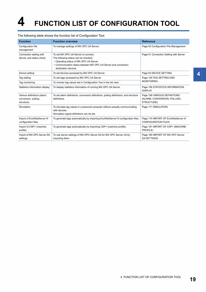
4 FUNCTION LIST OF CONFIGURATION TOOL
The following table shows the function list of Configuration Tool.
Function Function overview Reference
Configuration file
management
To manage settings of MX OPC UA Server. Page 55 Configuration File Management
Connection setting with
Server, and status check
To set MX OPC UA Server to connect.
The following status can be checked.
• Operating status of MX OPC UA Server
• Communication status between MX OPC UA Server and connection
destination devices
Page 61 Connection Setting with Server
Device setting To set devices accessed by MX OPC UA Server. Page 63 DEVICE SETTING
Tag setting To set tags accessed by MX OPC UA Server. Page 129 TAG SETTING AND
MONITORINGTag monitoring To monitor tag values set in Configuration Tool in the list view.
Statistics information display To display statistics information of running MX OPC UA Server. Page 156 STATISTICS INFORMATION
DISPLAY
Various definitions (alarm,
conversion, polling,
structure)
To set alarm definitions, conversion definitions, polling definitions, and structure
definitions.
Page 158 VARIOUS DEFINITIONS
(ALARM, CONVERSION, POLLING,
STRUCTURE)
Simulation To simulate tag values in a personal computer without actually communicating
with devices.
Simulation signal definitions can be set.
Page 171 SIMULATION
Import of EcoWebServer III
configuration files
To generate tags automatically by importing EcoWebServer III configuration files. Page 174 IMPORT OF EcoWebServer III
CONFIGURATION FILES
Import of CSP+ (machine
profile)
To generate tags automatically by importing CSP+ (machine profile). Page 181 IMPORT OF CSP+ (MACHINE
PROFILE)
Import of MX OPC Server DA
settings
To use server settings of MX OPC Server DA for MX OPC Server UA by
importing them.
Page 185 IMPORT OF MX OPC Server
DA SETTINGS

204 FUNCTION LIST OF CONFIGURATION TOOL
MEMO

5 OPERATING PROCEDURE (FLOW) 21
5
5 OPERATING PROCEDURE (FLOW)
This chapter shows the operating procedure to start MX OPC Server UA.
Page 24 START AND END
Page 38 Start and End
Page 27 Client Certificates
Page 56 Creating configuration files
Page 63 Newly adding or editing MX devices
Page 70 Newly adding or editing Modbus devices
Page 77 Setting Connection Destinations
Page 64 MX device screen setting
Start
Installing MX OPC Server UA
Starting MX OPC UA Server *1
Starting Configuration Tool
Creating a certificate of Configuration Tool *2
Creating a new MX OPC UA Server setting
Configuring device settings
Create a device.
Perform a communication test to check the connection setting.
Set the device. *3
Set a connection destination. *3
Configuring device tag settings
Set an alarm definition. *3
Set a polling definition. *3
Set a group. *3
Create a device tag.
Set a conversion definition. *3
Set the device tag.

225 OPERATING PROCEDURE (FLOW)
*1 When MX OPC Server UA is not installed as a service, start it manually.*2 Create it only when starting Configuration Tool for the first time or the certificate is expired.*3 Set it only when necessary.
Page 158 Setting Alarm Definitions
Page 164 Setting Conversion Definitions
Page 166 Setting Polling Definitions
Page 143 Newly adding or editing groups
Page 129 Address Space (Tag) Setting
Page 168 Setting Structure Definitions
Page 145 Newly adding or editing structure labels
Page 58 Saving configuration files
Page 154 Monitoring
Setting structure labels *3
Set a structure definition.
Create structure labels.
Saving settings to MX OPC UA Server
Checking the operation
Check the operation by monitoring the device.
Running the system
23
PA
RT
2
PART 2 SERVER FUNCTIONS
This part explains the functions of MX OPC UA Server.
6 START AND END
7 SECURITY OF MX OPC Server UA
8 SYSTEM CONFIGURATION
9 COMMUNICATION FUNCTION

246 START AND END
6 START AND END
The following shows the operating procedures to start and end MX OPC UA Server as a process.
When installing MX OPC UA Server as a service, these operations are not required.
Start
Operating procedure
Select [MELSOFT] [MX OPC UA]*2 [MELSOFT MX OPC Server UA]*3 from Windows Start*1.
When Server is started, an icon ( ) is displayed on the task tray.
*1 Select [All apps] in the Start screen or [Start] [All Programs]/[All apps].*2 Does not appear in Windows 8 or later.*3 MELSOFT MX OPC Server UA is automatically added to the start menu after installed.
Precautions
When Windows on which Server is running is in any of the following state, Server cannot be connected.
If the personal computer has already been connected to Server, the connection will be disconnected.
• Sleep
• Hibernate
• Shutdown
End
Operating procedure
Right-click the icon ( ) on the task tray, and select "Close MELSOFT MX OPC Server UA".

6 START AND END 25
6
MEMO
267 SECURITY OF MX OPC Server UA7.1 Certificate Management
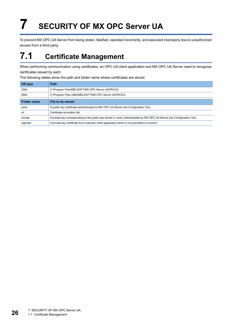
7 SECURITY OF MX OPC Server UA
To prevent MX OPC UA Server from being stolen, falsified, operated incorrectly, and executed improperly due to unauthorized
access from a third party.
7.1 Certificate ManagementWhen performing communication using certificates, an OPC UA client application and MX OPC UA Server need to recognize
certificates issued by each.
The following tables show the path and folder name where certificates are stored.
OS type Path
32bit C:\Program Files\MELSOFT\MX OPC Server UA\PKI\CA
64bit C:\Program Files (x86)\MELSOFT\MX OPC Server UA\PKI\CA
Folder name File to be stored
certs A public key certificate authenticated by MX OPC UA Server and Configuration Tool.
crl Certificate revocation list
private A private key corresponding to the public key stored in 'certs' authenticated by MX OPC UA Server and Configuration Tool.
rejected A private key certificate from unknown client application which is not permitted to connect.

7 SECURITY OF MX OPC Server UA7.2 Client Certificates 27
7
7.2 Client CertificatesA client certificate is generated when starting Configuration Tool for the first time.
Set necessary items in the following screen that appears when generating a certificate.
Window
Displayed items
Item Description
Subject Common name Set an arbitrary name for MX OPC UA Server.
Organization name Set the name of organization or company. (Example: Mitsubishi Electric)
Organization unit Set the unit/department within the organization or company. (Example: Planning dept)
Locality Set the town or city where the company is located.
State Set the prefecture/state where the company is located.
Country Set the two-letter ISO 3166-1 code of the country where MX OPC UA Server is used.
Example: Japan 'JP', America 'US', England 'GB', China 'CN', Germany 'DE', Italy 'IT'
OPC UA
Information
Domain Name Set the domain name of the personal computer where Configuration Tool is installed.
IP Address If no DNS name is available, enter the IP address of the personal computer where Configuration Tool is
installed.
Certificate
Settings
RSA Key Strength Set the strength of the key to generate. Larger numbers are stronger.
Certificate Validity Select the duration for which the certificate is valid.
Password protect private
key
Select this to protect the private key by a password.
Password Set the password for the private key.
Password (repeat) Enter the password for the private key again.
287 SECURITY OF MX OPC Server UA7.3 Server Certificates
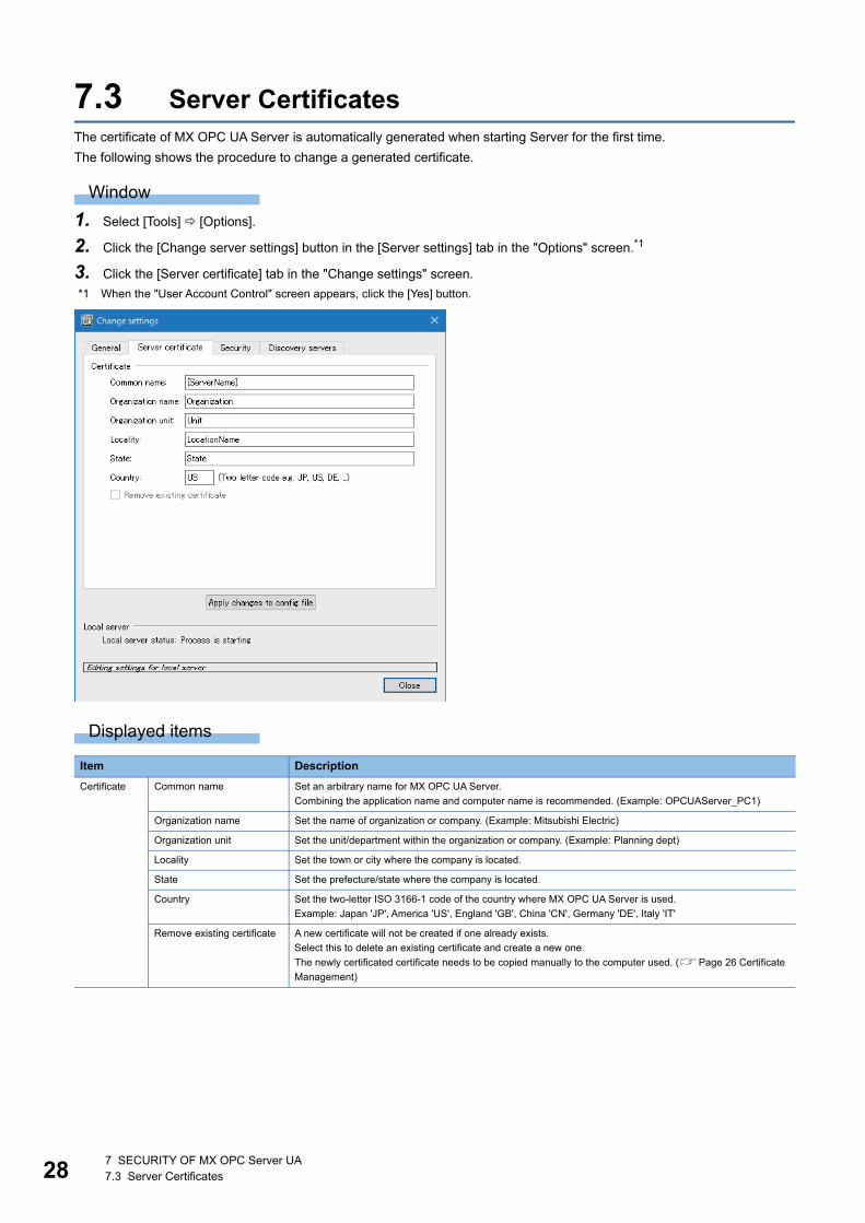
7.3 Server CertificatesThe certificate of MX OPC UA Server is automatically generated when starting Server for the first time.
The following shows the procedure to change a generated certificate.
Window
1. Select [Tools] [Options].
2. Click the [Change server settings] button in the [Server settings] tab in the "Options" screen.*1
3. Click the [Server certificate] tab in the "Change settings" screen.
*1 When the "User Account Control" screen appears, click the [Yes] button.
Displayed items
Item Description
Certificate Common name Set an arbitrary name for MX OPC UA Server.
Combining the application name and computer name is recommended. (Example: OPCUAServer_PC1)
Organization name Set the name of organization or company. (Example: Mitsubishi Electric)
Organization unit Set the unit/department within the organization or company. (Example: Planning dept)
Locality Set the town or city where the company is located.
State Set the prefecture/state where the company is located.
Country Set the two-letter ISO 3166-1 code of the country where MX OPC UA Server is used.
Example: Japan 'JP', America 'US', England 'GB', China 'CN', Germany 'DE', Italy 'IT'
Remove existing certificate A new certificate will not be created if one already exists.
Select this to delete an existing certificate and create a new one.
The newly certificated certificate needs to be copied manually to the computer used. (Page 26 Certificate
Management)

7 SECURITY OF MX OPC Server UA7.4 Security Setting for MX OPC UA Server 29
7
7.4 Security Setting for MX OPC UA ServerThe security setting of MX OPC UA Server can be changed.
Window
1. Select [Tools] [Options].
2. Click the [Change server settings] button in the [Server settings] tab in the "Options" screen.*1
3. Select the [Security] tab to set the following items.
4. Click the [Apply changes to config file] button.
*1 When the "User Account Control" screen appears, click the [Yes] button.
Displayed items
Item Description
Security Automatic certificate
exchange
When "On" is selected, Server exchanges certificate details with the Windows certificate store.
Unsecured
connections
Set whether to accept or reject connections which are not protected by any security.
• "On": A connection with no encryption is permitted.
• "Off": A connection with encryption of less than 128 bits is not permitted.

308 SYSTEM CONFIGURATION
8 SYSTEM CONFIGURATION
This chapter shows the system configuration when using MX OPC UA Server for each communication method.
Personal computer
Personal computer
Serial communication R series-compatible C24,Q series-compatible C24, L series-compatible C24
FX extended port(FX***-485-BD, FX***-485ADP)
Ethernet module, Built-in Ethernet port CPU
GOT
CC-Link IE Field Network module
Ethernet adapter/module
FX5CPU (FX5-232-BD, FX5-232ADP)
QCPU (Q mode), LCPU, Q Motion, FXCPU
Modbus module
Modbus module
CC-Link IE controller Network module
CC-Link IE Field Network module
CC-Link module(Software version "N" or later)
RCPU, QCPU (Q mode, LCPU, NCCPU(M8), EcoWebServerⅢ
GX Works2 Version 1(SW1DNC-GXW2-E) or laterMust be purchased separately
FXCPU(FX3S/FX3G/FX3GC/FX3GE/FX3U/FX3UC)
RCPU, R Motion CPU, R Safety, QCPU (Q mode),LCPU, Q Motion CPU, FXCPU (FX3G)
Ethernet communication
CPU COM communication
CPU USB communication
CC-Link IE Controller Network communication
CC-Link IE Field Network communication
CC-Link communication
SLMP communication
GX Simulator2communication
Simulation function of GX Works2(GX Simulator2)
RS-232
RS-232
RS-232
CC-Link Ver.2 board
CC-Link IE Controller Network board
CC-Link IE Field Network board
USB
Ethernet
Ethernet board
Ethernet board
Ethernet board
Ethernet adapter module
CC-Link IE Field Network
Converter/cable
RS-232/RS-485 conversion
RS-232, RS-232/RS-422 conversion
<MX device>
<Modbus device>

8 SYSTEM CONFIGURATION 31
8
MEMO
329 COMMUNICATION FUNCTION9.1 Communication with Devices and Tags
9 COMMUNICATION FUNCTION
This chapter explains the communication function of MX OPC UA Server.
9.1 Communication with Devices and TagsMX OPC UA Server communicates with devices and tags set in Configuration Tool.
It is possible to enable or disable communication for each device or each tag, and prevent errors from unconnected devices
from being displayed when starting the system.
Enabling communication with devicesThe following shows the procedure to enable communication with a device.
For the settings of MX devices and Modbus devices, refer to the following section.
Page 63 Address Space (Access Target Device) Setting
MX deviceThe following shows the procedure to enable communication with an MX device.
Operating procedure
1. Double-click an MX device in the tree view of Configuration Tool.
The "Device Properties" screen appears.
2. Select "Enable Device" under "Primary Device" in the [Advanced] tab.
3. When enabling communication with a backup device, select "Enable Device" under "Backup Device".
4. Click the [Save] button.
Modbus deviceThe following shows the procedure to enable communication with a Modbus device.
Operating procedure
1. Double-click a Modbus device in the tree view of Configuration Tool.
The "Device properties" screen appears.
2. Select "Enable" in the [Basic] tab.
3. Click the [Save] button.
9 COMMUNICATION FUNCTION9.1 Communication with Devices and Tags 33
9Enabling communication with tagsThe following shows the procedure to enable communication with a tag.
For the settings of MX device tags and Modbus device tags, refer to the following section.
Page 129 Address Space (Tag) Setting
MX device tagThe following shows the procedure to enable communication with an MX device tag.
Operating procedure
1. Double-click an MX device tag in the list view of Configuration Tool.
The "Tag Properties" screen appears.
2. Select "Enable Tag" in the [Advanced] tab.
3. Click the [Save] button.
Modbus device tagThe following shows the procedure to enable communication with a Modbus device tag.
Operating procedure
1. Double-click a Modbus device tag in the list view of Configuration Tool.
The "Data item properties" screen appears.
2. Select "Enable Tag" in the [Advanced] tab.
3. Click the [Save] button.
349 COMMUNICATION FUNCTION9.2 Starting or Stopping Polling
9.2 Starting or Stopping PollingThis section shows the procedure to start or stop polling new MX devices, Modbus devices, or tags defined in Configuration
Tool.
By starting polling, communication with devices and tags starts.
For monitoring data sampled by MX OPC UA Server in Configuration Tool, refer to the following section.
Page 154 Monitoring
Start
Selected devices or tagsThe following shows the procedure to start polling selected devices or tags.
Operating procedure
1. Select a device or a tag in the tree view or the list view of Configuration Tool.
2. Right-click it and select [Start selected device(s)].
Click the icon on the toolbar to start polling.
All devicesThe following shows the procedure to start polling all devices.
Operating procedure
Click the icon on the toolbar.
Stop
Selected devices or tagsThe following shows the procedure to stop polling selected devices or tags.
Operating procedure
1. Select a device or a tag in the tree view or the list view of Configuration Tool.
2. Right-click it and select [Stop selected device(s)].
Click the icon on the toolbar to stop polling.
All devicesThe following shows the procedure to stop polling all devices.
Operating procedure
Click the icon on the toolbar.
9 COMMUNICATION FUNCTION9.2 Starting or Stopping Polling 35
9
Precautions
Do not change the date and time of the personal computer while MX OPC UA Server is acquiring data in a device.
If changing the current date and time to that of 49 days before or that of 49 days later, MX OPC UA Server may stop.
To change it, stop MX OPC UA Server.
Time stamps and data values may be updated at shorter intervals than usual in the screen of a client application.
In this case, perform any of the following operations.
• Reopen the screen being monitored.
• Select [View] [Refresh] to update the screen of Configuration Tool.
• Restart MX OPC UA Server.

369 COMMUNICATION FUNCTION9.2 Starting or Stopping Polling
MEMO
37
PA
RT
3
PART 3 CONFIGURATION TOOL FUNCTIONS
This part explains the functions of MELSOFT MX OPC Server UA Configuration Tool.
10 SCREEN CONFIGURATION AND BASIC OPERATIONS
11 SERVER CONNECTION
12 DEVICE SETTING
13 TAG SETTING AND MONITORING
14 STATISTICS INFORMATION DISPLAY
15 VARIOUS DEFINITIONS (ALARM, CONVERSION, POLLING, STRUCTURE)
16 SIMULATION
17 IMPORT OF EcoWebServer III CONFIGURATION FILES
18 IMPORT OF CSP+ (MACHINE PROFILE)
19 IMPORT OF MX OPC Server DA SETTINGS

3810 SCREEN CONFIGURATION AND BASIC OPERATIONS10.1 Start and End
10 SCREEN CONFIGURATION AND BASIC OPERATIONS
This chapter explains the screen configuration and operation methods of Configuration Tool.
10.1 Start and EndThis section shows the procedure to start and end Configuration Tool.
Start
Operating procedure
1. Select [MELSOFT]*2 [MX OPC UA] [MELSOFT MX OPC Server UA Configuration Tool] from Windows Start*1.
2. When starting Configuration Tool for the first time, set each item in the "New Application Instance Certificate" screen and
click the [OK] button. (Page 27 Client Certificates)
*1 Select [All apps] in the Start screen or [Start] [All Programs]/[All apps].*2 Does not appear in Windows 8 or later.
Precautions
• The name of a program folder may depend on local settings (such as a language setting).
• Operations when starting Configuration Tool can be set in the option setting. (Page 44 Option Settings)
End
Operating procedure
Select [File] [Exit].
10 SCREEN CONFIGURATION AND BASIC OPERATIONS10.2 Screen Configuration 39
10
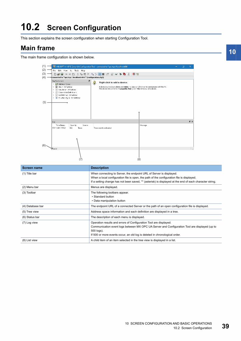
10.2 Screen ConfigurationThis section explains the screen configuration when starting Configuration Tool.
Main frameThe main frame configuration is shown below.
Screen name Description
(1) Title bar When connecting to Server, the endpoint URL of Server is displayed.
When a local configuration file is open, the path of the configuration file is displayed.
If a setting change has not been saved, '*' (asterisk) is displayed at the end of each character string.
(2) Menu bar Menus are displayed.
(3) Toolbar The following toolbars appear.
• Standard button
• Data manipulation button
(4) Database bar The endpoint URL of a connected Server or the path of an open configuration file is displayed.
(5) Tree view Address space information and each definition are displayed in a tree.
(6) Status bar The description of each menu is displayed.
(7) Log view Operation results and errors of Configuration Tool are displayed.
Communication event logs between MX OPC UA Server and Configuration Tool are displayed (up to
500 logs).
If 500 or more events occur, an old log is deleted in chronological order.
(8) List view A child item of an item selected in the tree view is displayed in a list.
(8)(7)
(5)
(1)(2)(3)(4)
(6)

4010 SCREEN CONFIGURATION AND BASIC OPERATIONS10.3 Menu List
10.3 Menu ListThe following tables show the menu lists of Configuration Tool.
[File]
[New] To create new settings of MX OPC UA Server. Page 56 Creating configuration files
[Open File] To open configuration files (local) of MX OPC UA Server. Page 57 Local file
[Open Server] To open configuration files (Server) of MX OPC UA Server. Page 57 Server
[Save] To save settings of MX OPC UA Server.
• Save destination when connecting to MX OPC UA Server: MX
OPC UA Server
• Save destination when not connecting to MX OPC UA Server:
Configuration file (local)
Page 58 Overwriting and saving
[Save to file] To save settings of MX OPC UA Server to configuration files (local). Page 58 Saving to a local file
[Save to server] To save settings of MX OPC UA Server to MX OPC UA Server. Page 59 Saving to a file in Server
[Delete from server] To delete settings from MX OPC UA Server. Page 60 Deleting configuration files
[Close] To close the connection with MX OPC UA Server.
[EcoWebServerIII configuration file
actions] [Import EcoWebServerIII
configuration file]
To import settings of setting files of EcoWebServer III. Page 174 Automatic Generation of
EcoWebServer III Tags
[CSP+(machine profile) actions]
[Import CSP+(machine profile)]
To import settings of CSP+ (machine profile). Page 181 Automatic Generation of Tags
Using CSP+ (Machine Profile)
[Import] [Import MX OPC DA
configuration]
To import settings of MX OPC Server DA. Page 185 Using Server Settings of MX
OPC Server DA
[Exit] To end Configuration Tool. Page 38 End
[Edit] (Available menus for Address Space)
[New MX Device] To create new MX devices. Page 63 Newly adding or editing MX
devices
[New Modbus Device] To create new Modbus devices. Page 70 Newly adding or editing Modbus
devices
[New Group] To create new groups. Page 143 Newly adding or editing groups
[New Data Tag] To create new MX device tags or Modbus device tags. Page 129 Address Space (Tag) Setting
[New Structure] To create new structure labels. Page 145 Newly adding or editing
structure labels
[Cut] To cut selected MX devices, Modbus devices, groups, MX device
tags, or Modbus device tags.
Page 43 Cut, Copy, or Paste
[Copy] To copy MX devices or Modbus devices.
[Paste] To paste copied or cut MX devices, Modbus devices, groups, MX
device tags, or Modbus device tags.
[Select All] To select all MX devices, Modbus devices, groups, MX device tags,
or Modbus device tags in the list view.
[Invert Selection] To unselect selected MX devices, Modbus devices, groups, MX
device tags, or Modbus device tags, and select unselected items.
[Delete] To delete selected MX devices, Modbus devices, groups, MX device
tags, or Modbus device tags.
[Properties] To display the properties of a selected item.

10 SCREEN CONFIGURATION AND BASIC OPERATIONS10.3 Menu List 41
10
[Edit] (Available menus for Alarm Definitions)
[New Limit Alarm Definition] To create new limit alarm definitions. Page 158 New
[New Digital Alarm Definition] To create new digital alarm definitions. Page 161 New
[Cut] To cut selected limit alarm definitions or digital alarm definitions. Page 43 Cut, Copy, or Paste
[Copy] To copy selected limit alarm definitions or digital alarm definitions.
[Paste] To paste copied or cut limit alarm definitions or digital alarm
definitions.
[Select All] To select all limit alarm definitions or digital alarm definitions in the
list view.
[Invert Selection] To unselect selected limit alarm definitions or digital alarm
definitions, and select unselected definitions in the list view.
[Delete] To delete selected limit alarm definitions or digital alarm definitions. Page 163 Deleting alarm definitions
[Properties] To display the property screen of a selected limit alarm definition or
digital alarm definition.
[Edit] (Available menus for Simulation Definitions)
[New Simulation Signal] To create new simulation definitions. Page 171 New
[Cut] To cut selected simulation definitions. Page 43 Cut, Copy, or Paste
[Copy] To copy selected simulation definitions.
[Paste] To paste copied or cut simulation definitions.
[Select All] To select all simulation definitions in the list view.
[Invert Selection] To unselect selected simulation definitions, and select unselected
definitions in the list view.
[Delete] To delete selected simulation definitions. Page 173 Deleting simulation signal
definitions
[Properties] To display the property screen of a selected simulation definition.
[Edit] (Available menus for Conversion Definitions)
[New Conversion] To create new conversion definitions. Page 164 New
[Cut] To cut selected conversion definitions. Page 43 Cut, Copy, or Paste
[Copy] To copy selected conversion definitions.
[Paste] To paste copied or cut conversion definitions.
[Select All] To select all conversion definitions in the list view.
[Invert Selection] To unselect selected conversion definitions, and select unselected
definitions in the list view.
[Delete] To delete selected conversion definitions. Page 165 Deleting conversion definitions
[Properties] To display the property screen of a selected conversion definition.
[Edit] (Available menus for Poll Method Definitions)
[New Polling Method] To create new polling definitions. Page 166 New
[Cut] To cut selected polling definitions. Page 43 Cut, Copy, or Paste
[Copy] To copy selected polling definitions.
[Paste] To paste copied or cut polling definitions.
[Select All] To select all polling definitions in the list view.
[Invert Selection] To unselect selected polling definitions, and select unselected
definitions in the list view.
[Delete] To delete selected polling definitions. Page 167 Deleting polling definitions
[Properties] To display the property screen of a selected polling definition.
4210 SCREEN CONFIGURATION AND BASIC OPERATIONS10.3 Menu List
[Edit] (Available menus for Structure Type Declarations)
[New StructureType] To create new structure definitions. Page 168 New
[Cut] To cut selected structure definitions. Page 43 Cut, Copy, or Paste
[Copy] To copy selected structure definitions.
[Paste] To paste copied or cut structure definitions.
[Select All] To select all structure definitions in the list view.
[Invert Selection] To unselect selected structure definitions, and select unselected
definitions in the list view.
[Delete] To delete selected structure definitions. Page 170 Deleting structure definitions
[Properties] To display the property screen of a selected structure definition.
[View]
[Toolbars] [Standard Buttons] To show or hide the standard buttons.
[Toolbars] [Data Manipulation
Buttons]
To show or hide the data manipulation buttons.
[Database bar] To show or hide the database bar.
[Status Bar] To show or hide the status bar.
[Log] To show or hide the log.
[Large Icons] To display items in the list view in large icons.
[Small Icons] To display items in the list view in small icons.
[List] To display items in the list view in a list.
[Details] To display items in the list view in detail.
[Statistics] To display the statistics screen. Page 156 Display Method
[Monitor view] To start or stop monitoring. Page 154 Monitoring
[Diagnostics] To display the screen of the connected Server status. Page 62 Status of a connected server
[Sort by] [Name] To sort items displayed in the list view.
[Show/hide columns] [Description] To select columns displayed in the list view when displaying items in
detail.
[Refresh] To update the screen.
[Go]
[Back] To go back to the previously selected item.
[Forward] To cancel the [Back] operation.
[Up one level] To move up one level in the tree view.
[Next Item] To move to the next item in the tree view.
[Previous Item] To move to the previous item in the tree view.
[Expand Item] To expand a selected item in the tree view.
[Collapse Item] To collapse a selected item in the tree view.
[Page Up] To scroll up the page in the tree view.
[Page Down] To scroll down the page in the tree view.
[Home] To move up to the top item in the tree view.
[End] To move down to the bottom item in the tree view.
[Next Pane] To switch the focus to the next pane.
[Previous Pane] To switch the focus to the previous pane.
[Tools]
[Options] To display the option screen. Page 44 Option Settings
[Connection settings] To display connection settings. Page 61 Setting a connection with Server
[Help]
[Help Topics] To start e-Manual Viewer and display the manual. Page 54 Displaying Help
[About Application] To display the version information screen. Page 54 Checking the version of
Configuration Tool
10 SCREEN CONFIGURATION AND BASIC OPERATIONS10.4 Cut, Copy, or Paste 43
10
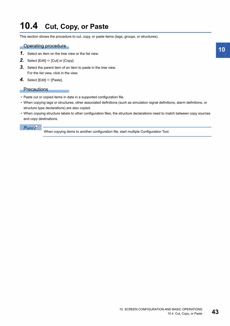
10.4 Cut, Copy, or PasteThis section shows the procedure to cut, copy, or paste items (tags, groups, or structures).
Operating procedure
1. Select an item on the tree view or the list view.
2. Select [Edit] [Cut] or [Copy].
3. Select the parent item of an item to paste in the tree view.
For the list view, click in the view.
4. Select [Edit] [Paste].
Precautions
• Paste cut or copied items in data in a supported configuration file.
• When copying tags or structures, other associated definitions (such as simulation signal definitions, alarm definitions, or
structure type declarations) are also copied.
• When copying structure labels to other configuration files, the structure declarations need to match between copy sources
and copy destinations.
When copying items to another configuration file, start multiple Configuration Tool.

4410 SCREEN CONFIGURATION AND BASIC OPERATIONS10.5 Option Settings
10.5 Option SettingsThis section shows the option settings of Configuration Tool and MX OPC UA Server.
Window
[Tools] [Options]
The "Options" screen consists of the following tabs:
(1) in the screen indicates the setting destination of items in each tab.
• For a discovery server setting: "Editing settings for server (endpoint URL)"
• For local Server setting: "Editing settings for local server"
Tab name Description
General Set the operation when starting Configuration Tool and MX OPC UA Server.
Logging Set log output during MX OPC UA Server communication.
Server settings The current server settings are displayed.
Server settings can be changed.
Firewall The firewall status is displayed.
A firewall setting can be changed.
(1)

10 SCREEN CONFIGURATION AND BASIC OPERATIONS10.5 Option Settings 45
10
General settingSet the operation when starting Configuration Tool and MX OPC UA Server.
*1 Can be set when connecting to Server.
Item Description
Startup settings (Configuration Tool) Select an operation when starting Configuration Tool.
• Open the most recently-used server/file
• Open local server
• Open this server
• Open a specific file
Workspace settings Statistics Refresh Rate Set an update frequency of an item in the "Statistics" screen. (In milliseconds)
Startup settings (Server)*1 Set an operation when starting Server.
• Open the most recently-used file
• Open a specific file
4610 SCREEN CONFIGURATION AND BASIC OPERATIONS10.5 Option Settings
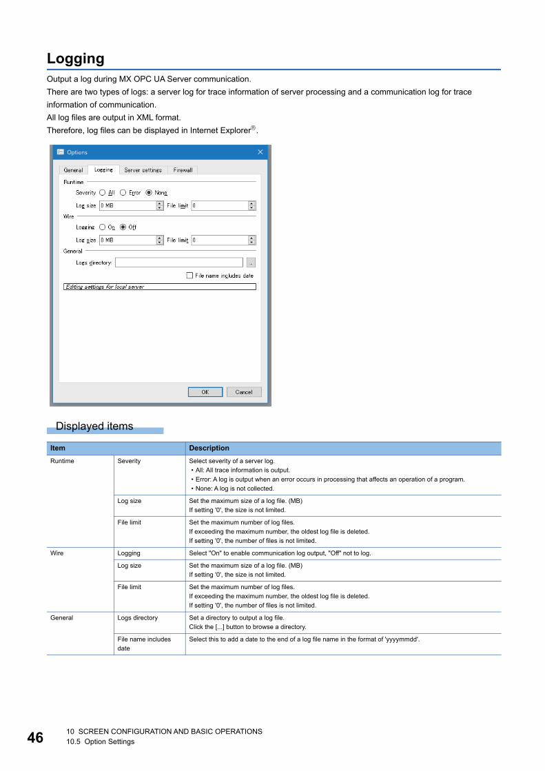
LoggingOutput a log during MX OPC UA Server communication.
There are two types of logs: a server log for trace information of server processing and a communication log for trace
information of communication.
All log files are output in XML format.
Therefore, log files can be displayed in Internet Explorer.
Displayed items
Item Description
Runtime Severity Select severity of a server log.
• All: All trace information is output.
• Error: A log is output when an error occurs in processing that affects an operation of a program.
• None: A log is not collected.
Log size Set the maximum size of a log file. (MB)
If setting '0', the size is not limited.
File limit Set the maximum number of log files.
If exceeding the maximum number, the oldest log file is deleted.
If setting '0', the number of files is not limited.
Wire Logging Select "On" to enable communication log output, "Off" not to log.
Log size Set the maximum size of a log file. (MB)
If setting '0', the size is not limited.
File limit Set the maximum number of log files.
If exceeding the maximum number, the oldest log file is deleted.
If setting '0', the number of files is not limited.
General Logs directory Set a directory to output a log file.
Click the [...] button to browse a directory.
File name includes
date
Select this to add a date to the end of a log file name in the format of 'yyyymmdd'.

10 SCREEN CONFIGURATION AND BASIC OPERATIONS10.5 Option Settings 47
10
Server settingA setting currently applied to Server is displayed.
Displayed items
Precautions
When Server setting is changed, Server may need to be restarted.
Make sure to save the change before restarting Server.
Item Description
General Configuration files directory A directory to store a configuration file is displayed.
An invalid path is displayed in red.
Security Automatic certificate exchange "On" is displayed when exchanging certificates automatically with Windows certificate store,
otherwise "Off".
Unsecured connections "On" is displayed when Server approves an unencrypted connection, otherwise "Off".
Discovery servers Register with discovery servers MX OPC UA Server is registered in each server in this list.
Registration interval An interval to register Server in a local discovery server is displayed. (In milliseconds)
Server certificate Common name An OPC UA Server name used for an X509 certificate that is created automatically is displayed.
Organization An organization name (such as company name) used for an X509 certificate is displayed.
Local server Local server status The status of MX OPC UA Server is displayed.
[Change server settings] button Click this to change Server setting. (Page 48 Changing Server settings)

4810 SCREEN CONFIGURATION AND BASIC OPERATIONS10.5 Option Settings
Changing Server settingsChange a setting used in Server.
Window
1. Select [Tools] [Options].
2. Click the [Change server settings] button in the [Server settings] tab in the "Options" screen.*1
*1 When the "User Account Control" screen appears, click the [Yes] button.
The "Change settings" screen consists of the following tabs:
• [General] tab
• [Server certificate] tab
• [Security] tab
• [Discovery servers] tab
Click the [Apply changes to config file] button to save after changing a setting on any of the tabs.
To enable a changed setting, restart MX OPC UA Server.
The status of MX OPC UA Server is displayed in "Local server" at the bottom in the screen.
If not restarting Server after applying a setting change to a file, a warning is displayed as shown below.

10 SCREEN CONFIGURATION AND BASIC OPERATIONS10.5 Option Settings 49
10
■General settingSet a directory to save a configuration file.
Displayed items
Item Description
General Configuration files
directory
Set a directory to save a configuration file.
Enter it directly, or click the [...] button to select a directory.
5010 SCREEN CONFIGURATION AND BASIC OPERATIONS10.5 Option Settings
■Server certificateDetails of a certificate used when creating an X509 certificate are displayed.
For details, refer to the following section.
Page 28 Server Certificates
■SecurityChange a security setting.
For details, refer to the following section.
Page 29 Security Setting for MX OPC UA Server

10 SCREEN CONFIGURATION AND BASIC OPERATIONS10.5 Option Settings 51
10
■Discovery serverA setting of a local discovery server is displayed.
Displayed items
Item Description
Discovery servers Register with
discovery servers
The URL of a local discovery server to register Server is displayed.
• Double-click the URL of a discovery server in the list to change it.
• To add a discovery server, click the [Add discovery server] ( ) button, set Server name or an IP address,
and press the key.
• The display order of discovery servers can be changed by selecting Server and clicking the [Move up]
( ) button or the [Move down] ( ) button.
• To delete a discovery server, select one and click the [Remove discovery server] ( ) button.
• To search a computer on a local network, click the [Browse for discovery servers] ( ) button. The list of
computer names on a local network is displayed. Whether a discovery server is running or not is not
checked.
Registration interval Set an interval to register Server in a local discovery server. (In milliseconds)
5210 SCREEN CONFIGURATION AND BASIC OPERATIONS10.5 Option Settings
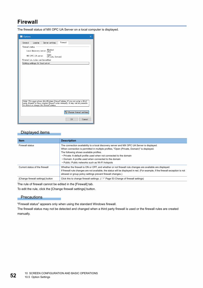
FirewallThe firewall status of MX OPC UA Server on a local computer is displayed.
Displayed items
The rule of firewall cannot be edited in the [Firewall] tab.
To edit the rule, click the [Change firewall settings] button.
Precautions
"Firewall status" appears only when using the standard Windows firewall.
The firewall status may not be detected and changed when a third party firewall is used or the firewall rules are created
manually.
Item Description
Firewall status The connection availability to a local discovery server and MX OPC UA Server is displayed.
When connection is permitted in multiple profiles, "Open (Private, Domain)" is displayed.
The following shows available profiles.
• Private: A default profile used when not connected to the domain
• Domain: A profile used when connected to the domain
• Public: Public networks such as Wi-Fi hotspots
Current status of the firewall Whether the firewall is ON or OFF, and whether or not firewall rule changes are available are displayed.
If firewall rule changes are not available, the status will be displayed in red. (For example, if the firewall exception is not
allowed or group policy settings prevent firewall changes.)
[Change firewall settings] button Click this to change firewall settings. (Page 53 Change of firewall settings)
10 SCREEN CONFIGURATION AND BASIC OPERATIONS10.5 Option Settings 53
10
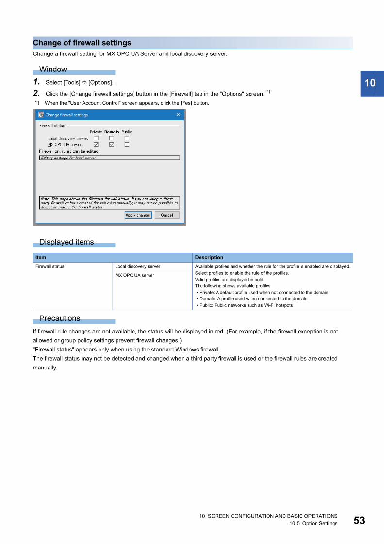
Change of firewall settingsChange a firewall setting for MX OPC UA Server and local discovery server.
Window
1. Select [Tools] [Options].
2. Click the [Change firewall settings] button in the [Firewall] tab in the "Options" screen. *1
*1 When the "User Account Control" screen appears, click the [Yes] button.
Displayed items
Precautions
If firewall rule changes are not available, the status will be displayed in red. (For example, if the firewall exception is not
allowed or group policy settings prevent firewall changes.)
"Firewall status" appears only when using the standard Windows firewall.
The firewall status may not be detected and changed when a third party firewall is used or the firewall rules are created
manually.
Item Description
Firewall status Local discovery server Available profiles and whether the rule for the profile is enabled are displayed.
Select profiles to enable the rule of the profiles.
Valid profiles are displayed in bold.
The following shows available profiles.
• Private: A default profile used when not connected to the domain
• Domain: A profile used when connected to the domain
• Public: Public networks such as Wi-Fi hotspots
MX OPC UA server
5410 SCREEN CONFIGURATION AND BASIC OPERATIONS10.6 Learning Operation Methods of Configuration Tool
10.6 Learning Operation Methods of Configuration ToolThis section explains the operation methods of Configuration Tool.
Displaying HelpUse Help to learn about operations and functions, and check error codes.
Operating procedure
Select [Help] [Help Topics] ( ).
e-Manual Viewer starts and the manual appears.
Checking the version of Configuration ToolInformation such as the software version of Configuration Tool is displayed.
Operating procedure
Select [Help] [About Application].

11 SERVER CONNECTION11.1 Configuration File Management 55
11
11 SERVER CONNECTION
This chapter explains connections between Configuration Tool and MX OPC UA Server.
11.1 Configuration File ManagementSettings of MX OPC UA Server are saved in a configuration file.
Version and setting file extensionThe following shows the extension of a configuration file for each version of Configuration Tool.
File management method and the status of Configuration ToolThis section explains the configuration file management method and the status of Configuration Tool using files.
Configuration file management methodThere are two methods for managing configuration files.
Precautions
Configuration Tool can neither open multiple configuration files at the same time nor be connected with multiple Server.
However, multiple configuration files can be opened by starting multiple Configuration Tool.
In this case, data can be copied and pasted between Configuration Tool. (Page 43 Cut, Copy, or Paste)
Status of Configuration ToolThe current status of Configuration Tool (such as the status of a configuration file and the connection status with Server) is
displayed in the database bar as follows:
Precautions
The database bar may not be displayed when a configuration file is changed by another client application while connecting to
Server.
Extension of configuration file Version of Configuration Tool
cfg 2.0.4 or earlier
cfg3 3.0.0 or later
Management method Description
Manage on a local computer Manage configuration files on a local computer.
The settings can be written to Server later, and used for communication.
Tags cannot be monitored.
Manage on Server Connect to MX OPC UA Server and edit files in Server.
Tags can be monitored and the values can be edited.
Status database bar
No configuration file is opened.
A created configuration file is not saved
yet.
A configuration file on the local
computer is being opened.
A configuration file is being opened
with Server connected.
5611 SERVER CONNECTION11.1 Configuration File Management
Creating configuration filesCreate a new configuration file.
Operating procedure
Select [File] [New] or click on the toolbar.

11 SERVER CONNECTION11.1 Configuration File Management 57
11
Opening configuration filesRead a saved configuration file from a local computer or Server.
Local file
Operating procedure
1. Select [File] [Open File].
2. Select a configuration file (*.cfg3 or *.cf), and click the [Open] button.
Server
Operating procedure
1. Select [File] [Open Server].
2. The server information to open the setting is displayed in "Server configuration". To open a setting on another server,
click the [Edit] button, and select Server on the "Connection settings" screen. For details, refer to the following section.
Page 61 Setting a connection with Server
3. To change Server to be connected, click the [Refresh] button to update the configuration name list.
4. Select a setting to open from the configuration name list, and click the [OK] button.

5811 SERVER CONNECTION11.1 Configuration File Management
Saving configuration filesSave a setting being edited to a file in a local computer or server.
Overwriting and saving
Operating procedure
Select [File] [Save] or click on the toolbar.
Saving with a name
■Saving to a local file
Operating procedure
1. Select [File] [Save to file].
2. Select a directory to save the file, and enter a name. Then, click the [Save] button.
11 SERVER CONNECTION11.1 Configuration File Management 59
11
■Saving to a file in Server
Operating procedure
1. Select [File] [Save to server].
2. Information on Server that the setting can be saved is displayed in "Server configuration".
To save it to another Server, click the [Edit] button and select Server to save in the "Connection settings" screen.
For details, refer to the following section.
Page 61 Setting a connection with Server
3. Set a name to save in "Configuration name".
Enter a name directly, or click the [...] button to select a configuration name.
The active setting is shown with '(*)' ( an asterisk in brackets) after its name.

6011 SERVER CONNECTION11.1 Configuration File Management
Deleting configuration filesDelete a configuration file.
Local fileDelete a configuration file directly from Windows Explorer.
File in Server
Operating procedure
1. Select [File] [Delete from server].
2. Select a configuration file to delete in the list, and click the [OK] button.
Precautions
An active configuration file is not listed and cannot be deleted.

11 SERVER CONNECTION11.2 Connection Setting with Server 61
11
11.2 Connection Setting with ServerThis section explains about connection with MX OPC UA Server.
Setting a connection with ServerConfigure the connection setting of Server that is necessary to open a configuration file or save settings in Server.
Operating procedure
1. Select [Tools] [Connection settings].
The "Connection settings" screen appears.
2. When the URL of target Server is known, enter it for "Endpoint Url" directly.
When searching for target Server through a discovery server, enter the URL in the field for "Discovery Url(s)" directly, or select
one in the list displayed by clicking the [Browse discovery server(s)] button.
3. Click the [OK] button to complete the connection setting.
If a connection to Server cannot be established, the following possibility may considered:
• The target server has not opened the firewall ports used by OPC UA.
• The target server does not recognize the certificate of the client application.

6211 SERVER CONNECTION11.2 Connection Setting with Server
Status of a connected serverThis section describes the status of MX OPC UA Server.
Window
Select [View] [Diagnostics].
Displayed items
Item Description
Start time The date and time when Server started is displayed.
Up time The elapsed time since Server started is displayed.
Server status The status of Server is displayed.
Subscription count The number of subscriptions managed by Server is displayed.
Version The software version of Server is displayed.
Session count The number of sessions of an OPC UA client application connected to Server is displayed.
Vendor info The vendor information of Server is displayed.
[Refresh] button The operating status of Server is updated to the latest information.

12 DEVICE SETTING12.1 Address Space (Access Target Device) Setting 63
12
12 DEVICE SETTING
This chapter explains the setting to communicate with MX devices and Modbus devices.
12.1 Address Space (Access Target Device) SettingThis section shows the setting of access target devices for MX OPC UA Server.
MX OPC UA Server can access MX devices and Modbus devices.
Newly adding or editing MX devicesThe following shows the procedure to newly add or edit an MX device.
New
Operating procedure
1. Select "Address Space" in the tree view.
2. Select [Edit] [New MX Device] ( ).
3. Set a connection destination in the "MX Transfer Setup" screen, and click the [OK] button. (Page 78 Adding new
connection destination settings)
4. Set each item in the "Device Properties" screen, and click the [Save] button. (Page 64 MX device screen setting)
Edit
Operating procedure
1. Double-click a target MX device name in the tree view.
2. Set each item in the "Device Properties" screen, and click the [Save] button. (Page 64 MX device screen setting)
6412 DEVICE SETTING12.1 Address Space (Access Target Device) Setting
MX device screen settingConfigure the settings for MX devices
Window
Select [Edit] [New MX Device] ( ) click the [Configure] button and set a connection destination click the [OK] button
■Basic
Displayed items
*1 Alphanumeric characters, underscores (_), and hyphens (-) can be used.However, numbers cannot be used for the first character.
*2 Appears only when selecting "Ethernet board" for "PC side I/F".*3 When a number to be added already exists, the number is skipped and the next available number is added.
Item Description
Name Set the name of an access target device. (Up to 32 characters)*1
This name is used by an application (OPC UA client) connected to MX OPC UA Server to access an access point on
a device.
When other items (such as tags, groups, or structures) are included in an access target device, a name cannot be
edited.
Desc Set the description of an access target device. (Up to 128 characters)
Primary Device [Configuration]
button
Click this to display the "MX Transfer Setup" screen.
PC Side I/F A communication route set in the "MX Transfer Setup" screen is displayed. (Page 79 PC side I/F)
Comment A comment set in the "MX Transfer Setup Wizard - Finished" screen is displayed.
Module Type*2 A module type set in the "MX Transfer Setup Wizard" screen is displayed.
Host*2 An IP address and a port number set in the "MX Transfer Setup Wizard" screen are displayed.
[Save] button Click this to save the setting and close the "Device Properties" screen.
[Save & New] button Click this to save the setting and add a new MX device.
• A sequential number is added to the name of an MX device to be added next. (DevDev0Dev1)*3
• When the last character of an MX device name is a number, it is incremented. (Dev00Dev01Dev02)*3

12 DEVICE SETTING12.1 Address Space (Access Target Device) Setting 65
12
Precautions
Check that a COM port selected in the "MX Transfer Setup" screen is not used for another channel or application.
If two channels are assigned to a same port, communication failure occurs on one of the channels.
If a channel is assigned to a COM port used for another application (such as alarm printer), an error may occur during driver
communication.

6612 DEVICE SETTING12.1 Address Space (Access Target Device) Setting
■Advanced
Displayed items
Item Description
Primary Device Enable Device Select this to enable device polling.
Unselect this to disable polling in the following cases:
• When displaying an error is unfavorable while replacing hardware due to repair or
maintenance
• When data sampling from all devices is not required and reducing the communication load
is required
• When disconnecting a device for debugging
Simulate Select this to simulate all tags in a device.
For simulation signals to use, refer to the following:
• For a tag that "Simulate" is selected, a set simulation signal definition is used.
• For a tag that "Simulate" is not selected, a value is incremented every one second within
the range between 1 and 100.
• A simulation value is not written to a connected device.
Reply timeout Set a response waiting time from a device after sending a request. (In milliseconds)
(Page 68 Reply timeout, number of retries, and delay time)
Number of retries Set the number of times to resend a request to establish communication when an error occurs
while establishing a communication line.
Delay time Set Server waiting time when there is no response to all retries. (In milliseconds)
(Page 68 Reply timeout, number of retries, and delay time)
Merge gap Set a value larger than the number of device points between tags when reading or writing
inconsecutive devices in a batch in one communication between MX OPC UA Server and an
MX device. (0 to 960 words) (Page 69 Merge gap)
Max count for R/W operation Set the maximum number of devices that can be read/written in a single batch operation.
The value is not required to be changed while the system is working normally.
Setting the value greater than the default is not recommended.
Example: When reading devices 'D1', 'D500', and 'D1000'
• When '2' is set: D1 and D500 are read by the first batch read operation, and D1000 is read
by the next batch read operation.
• When '3' is set: All of D1, D500, and D1000 are read by the first batch read operation.

12 DEVICE SETTING12.1 Address Space (Access Target Device) Setting 67
12
*1 When a number to be added already exists, the number is skipped and the next available number is added.
Backup Device Enable Device Select this to enable a backup device.
By selecting this, the communication target can be changed to a backup device when a
primary device failed in communication.
[Configuration] button Click this to display the "MX Transfer Setup" screen. (Page 77 Connection destination
setting for an MX device)
PC Side I/F A communication route set in the "MX Transfer Setup" screen is displayed. (Page 79 PC
side I/F)
Comment A comment set in the "MX Transfer Setup Wizard - Finished" screen is displayed.
Reply timeout Set a response waiting time from a device after sending a request. (In milliseconds)
(Page 68 Reply timeout, number of retries, and delay time)
Number of retries Set the number of times to resend a request to establish communication when an error occurs
while establishing a communication line.
Delay time Set Server waiting time when there is no response to all retries. (In milliseconds)
(Page 68 Reply timeout, number of retries, and delay time)
Merge gap Set a value larger than the number of device points between tags when reading or writing
inconsecutive devices in a batch in one communication between MX OPC UA Server and an
MX device. (0 to 960 words) (Page 69 Merge gap)
Max count for R/W operation Set the maximum number of devices that can be read/written in a single batch operation.
The value is not required to be changed while the system is working normally.
Setting the value greater than the default is not recommended.
Example: When reading devices 'D1', 'D500', and 'D1000'
• When '2' is set: D1 and D500 are read by the first batch read operation, and D1000 is read
by the next batch read operation.
• When '3' is set: All of D1, D500, and D1000 are read by the first batch read operation.
[Save] button Click this to save the setting and close the "Device Properties" screen.
[Save & New] button Click this to save the setting and add a new MX device.
• A sequential number is added to the name of an MX device to be added next.
(DevDev0Dev1)*1
• When the last character of an MX device name is a number, it is incremented.
(Dev00Dev01Dev02)*1
Item Description

6812 DEVICE SETTING12.1 Address Space (Access Target Device) Setting
Reply timeout, number of retries, and delay timeSet the reply timeout, number of retries, and delay time for each device separately.
After setting these items, the device operates as follows:
1. MX OPC UA Server sends a message to a device, and waits for a response from the device for the time set for "Reply
timeout".
2. When the device did not respond, MX OPC UA Server sends a message again for the number of times set for "Number
of retries".
3. After a message is sent for the number of retries, and the device still did not respond, MX OPC UA Server records the
data as a failure.
• A connection target device can be changed to a backup device while the backup device is enabled.
After waiting for the period set for "Delay time", MX OPC UA Server sends a message to read the same data from the
backup device.
Timeouts and response process are repeated for the backup device, and when MX OPC UA Server recognized that the
backup device is not in operation, the connection is started with the primary device.
• When a backup device is not enabled, MX OPC UA Server waits for the period set for "Delay time" and start communication
with the selected device.
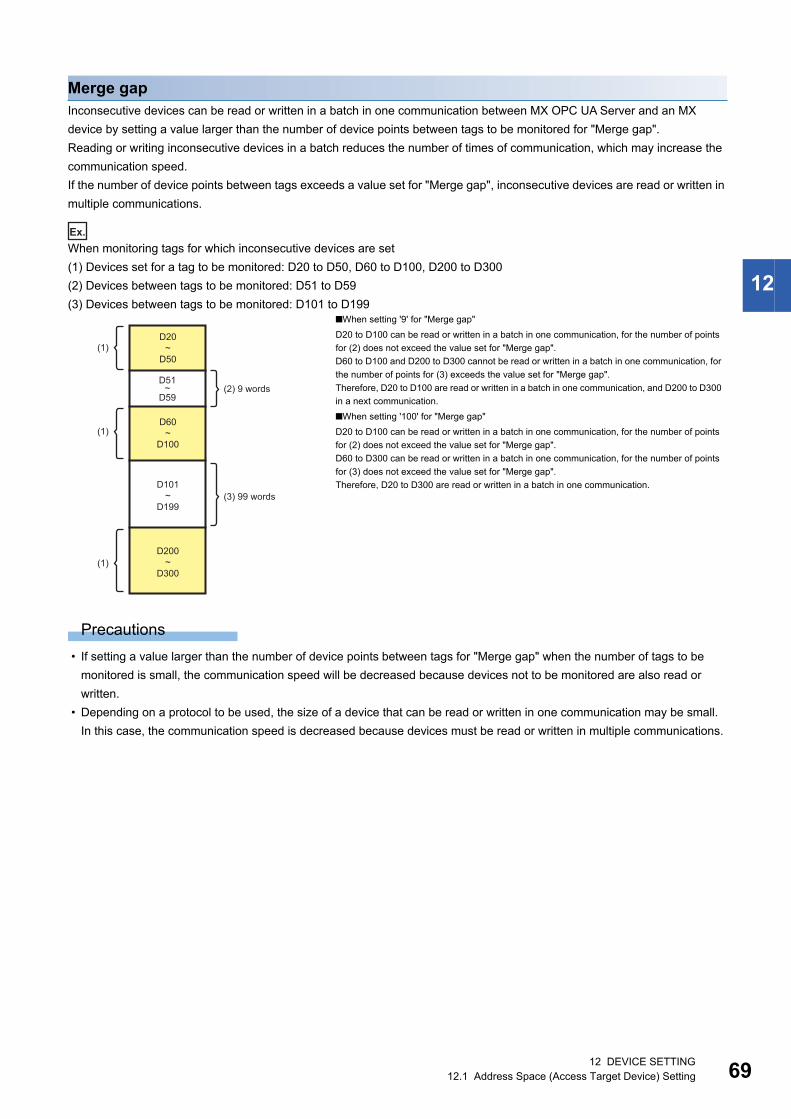
12 DEVICE SETTING12.1 Address Space (Access Target Device) Setting 69
12
Merge gapInconsecutive devices can be read or written in a batch in one communication between MX OPC UA Server and an MX
device by setting a value larger than the number of device points between tags to be monitored for "Merge gap".
Reading or writing inconsecutive devices in a batch reduces the number of times of communication, which may increase the
communication speed.
If the number of device points between tags exceeds a value set for "Merge gap", inconsecutive devices are read or written in
multiple communications.
Ex.
When monitoring tags for which inconsecutive devices are set
(1) Devices set for a tag to be monitored: D20 to D50, D60 to D100, D200 to D300
(2) Devices between tags to be monitored: D51 to D59
(3) Devices between tags to be monitored: D101 to D199
Precautions
• If setting a value larger than the number of device points between tags for "Merge gap" when the number of tags to be
monitored is small, the communication speed will be decreased because devices not to be monitored are also read or
written.
• Depending on a protocol to be used, the size of a device that can be read or written in one communication may be small.
In this case, the communication speed is decreased because devices must be read or written in multiple communications.
■When setting '9' for "Merge gap"
D20 to D100 can be read or written in a batch in one communication, for the number of points
for (2) does not exceed the value set for "Merge gap".
D60 to D100 and D200 to D300 cannot be read or written in a batch in one communication, for
the number of points for (3) exceeds the value set for "Merge gap".
Therefore, D20 to D100 are read or written in a batch in one communication, and D200 to D300
in a next communication.
■When setting '100' for "Merge gap"
D20 to D100 can be read or written in a batch in one communication, for the number of points
for (2) does not exceed the value set for "Merge gap".
D60 to D300 can be read or written in a batch in one communication, for the number of points
for (3) does not exceed the value set for "Merge gap".
Therefore, D20 to D300 are read or written in a batch in one communication.
D20~
D50
D60~
D100
D101~
D199
D200~
D300
D51~
D59(2) 9 words
(3) 99 words
(1)
(1)
(1)

7012 DEVICE SETTING12.1 Address Space (Access Target Device) Setting
Newly adding or editing Modbus devicesThe following shows the procedure to newly add or edit a Modbus device.
New
Operating procedure
1. Select "Address Space" in the tree view.
2. Select [Edit] [New Modbus Device].
3. Set each item in the "Device properties" screen, and click the [Save] button. (Page 70 Modbus device screen
setting)
Edit
Operating procedure
1. Double-click a target Modbus device name in the tree view.
2. Set each item in the "Device properties" screen, and click the [Save] button. (Page 70 Modbus device screen
setting)
Modbus device screen setting
Window
[Edit] [New Modbus Device]
■Basic
Displayed items
Item Description
Name Set the name of an access target device. (Up to 32 characters)*1
This name is used by an application (OPC UA client) connected to MX OPC UA Server to access an access
point on a device.
When other items (such as tags, groups, or structures) are included in an access target device, a name
cannot be changed.
Desc Set the description of an access target device. (Up to 128 characters)

12 DEVICE SETTING12.1 Address Space (Access Target Device) Setting 71
12
*1 Alphanumeric characters, underscores (_), and hyphens (-) can be used.However, numbers cannot be used for the first character.
*2 Available only when selecting "Ethernet Device".*3 Available only when selecting "Serial Device".*4 When a number to be added already exists, the number is skipped and the next available number is added.
Unit Identifier Set an identifier that indicates a device ID.
Simulate Select this to simulate all tags in a device.
For simulation signals to use, refer to the following:
• For a tag that "Simulate" is selected, a set simulation signal definition is used.
• For a tag that "Simulate" is not selected, a value is incremented every one second within the range between
1 and 100.
Enable Select this to enable device polling.
Unselect this to disable polling in the following cases:
• When displaying an error is unfavorable while replacing hardware due to repair or maintenance
• When data sampling from all devices is not required and reducing the communication load is required
• When disconnecting a device for debugging
Connection Ethernet Device Select this to connect to a device by using an Ethernet port.
IP Address*2 Set the host address of an Ethernet device. (Default: 255.255.255.0)
TCP Port*2 Set the TCP or IP port number of a device. (Default: 502)
Serial Device Select this to connect to a device by using a serial port.
Serial port*3 Set a serial port in the "Serial Port Details" screen. (Page 72 Serial port setting)
Device type Type Select a device type.
Parameters Enabled when selecting "Custom" for "Type".
Click the [Configure] button to display the "Device parameters" screen. (Page 73 Device parameters)
Data order For Modbus devices, the word or byte order depends on a device. (Page 74 Data order)
Select the order of data from the following:
• Default: Same order as Configuration Tool.
• Swap bytes: The order of bytes in each word is swapped.
• Swap words: The order of words of each word type (such as DINT, UDINT, REAL, LREAL) is swapped.
• Swap bytes & words: The order of words of each word and the order of bytes in each word are swapped.
String order Select the order of character strings from the following:
• High first: The upper two digits are displayed at the first in each word.
• Low first: The lower two digits are displayed at the first in each word.
[Save] button Click this to save the setting and close the "Device properties" screen.
[Save & New] button Click this to save the setting and add a new Modbus device.
• A sequential number is added to the name of a Modbus device to be added next. (DevDev0Dev1)*4
• When the last character of a Modbus device name is a number, it is incremented.
(Dev00Dev01Dev02)*4
Item Description

7212 DEVICE SETTING12.1 Address Space (Access Target Device) Setting
■Serial port settingSet the serial port of a device currently connected.
Window
1. Select "Serial Device" in "Connection" in the [Basic] tab in the "Device properties" screen.
2. Click the [Configure] button of "Serial port".
Displayed items
*1 Available when selecting "Even" or "Odd" for "Parity scheme".
Precautions
If a same port number is assigned to multiple channels, communication failure occurs on one of the channels.
If a channel is assigned to a COM port used for another application, an error may occur during driver communication.
Check that a selected COM port is not used for another channel or application.
Item Description
Port Set a port number.
Baud rate Select a baud rate.
Monitor CTS for output flow control Select this to enable monitoring of a CTS signal.
Transmission mode Select a transmission mode.
RTS flow control Select an RTS flow control.
Stop bits Select a stop bit.
Parity scheme Select a parity scheme to use.
Parity checking enabled*1 Select this to set whether or not to ignore a parity bit.

12 DEVICE SETTING12.1 Address Space (Access Target Device) Setting 73
12
■Device parametersSet device parameters.
Window
1. Select "Custom" for "Type" in the [Basic] tab in the "Device properties" screen.
2. Click the [Configure] button of "Parameters".
Displayed items
Item Description
Read Coils Set the maximum number of coils that can be transferred in one message when reading.
Inputs Set the maximum number of inputs that can be transferred in one message when reading.
Holding registers Set the maximum number of holding registers that can be transferred in one message when reading.
Input registers Set the maximum number of input registers that can be transferred in one message when reading.
Write Coils Set the maximum number of coils that can be transferred in one message when writing.
Holding registers Set the maximum number of holding registers that can be transferred in one message when writing.
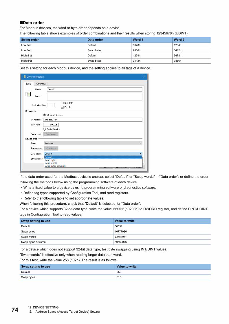
7412 DEVICE SETTING12.1 Address Space (Access Target Device) Setting
■Data orderFor Modbus devices, the word or byte order depends on a device.
The following table shows examples of order combinations and their results when storing 12345678h (UDINT).
Set this setting for each Modbus device, and the setting applies to all tags of a device.
If the data order used for the Modbus device is unclear, select "Default" or "Swap words" in "Data order", or define the order
following the methods below using the programming software of each device.
• Write a fixed value to a device by using programming software or diagnostics software.
• Define tag types supported by Configuration Tool, and read registers.
• Refer to the following table to set appropriate values.
When following this procedure, check that "Default" is selected for "Data order".
For a device which supports 32-bit data type, write the value '66051' (10203h) to DWORD register, and define DINT/UDINT
tags in Configuration Tool to read values.
For a device which does not support 32-bit data type, test byte swapping using INT/UINT values.
"Swap words" is effective only when reading larger data than word.
For this test, write the value 258 (102h). The result is as follows:
String order Data order Word 1 Word 2
Low first Default 5678h 1234h
Low first Swap bytes 7856h 3412h
High first Default 1234h 5678h
High first Swap bytes 3412h 7856h
Swap setting to use Value to write
Default 66051
Swap bytes 16777986
Swap words 33751041
Swap bytes & words 50462976
Swap setting to use Value to write
Default 258
Swap bytes 513
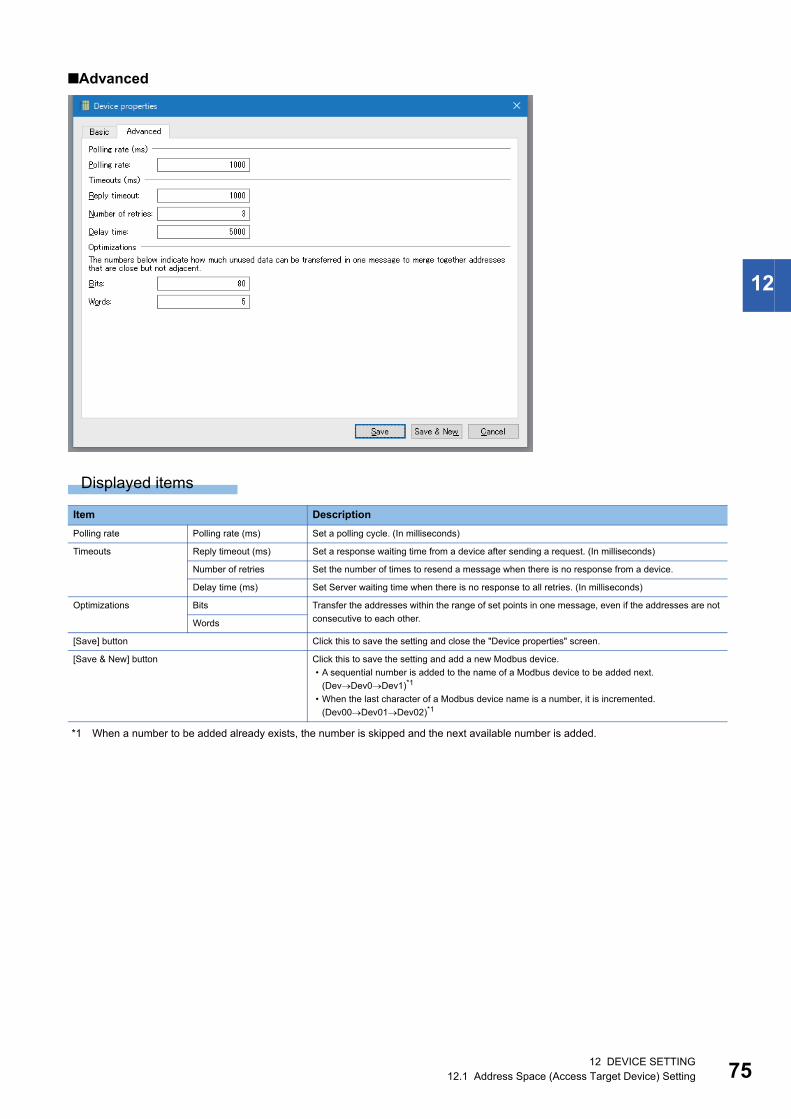
12 DEVICE SETTING12.1 Address Space (Access Target Device) Setting 75
12
■Advanced
Displayed items
*1 When a number to be added already exists, the number is skipped and the next available number is added.
Item Description
Polling rate Polling rate (ms) Set a polling cycle. (In milliseconds)
Timeouts Reply timeout (ms) Set a response waiting time from a device after sending a request. (In milliseconds)
Number of retries Set the number of times to resend a message when there is no response from a device.
Delay time (ms) Set Server waiting time when there is no response to all retries. (In milliseconds)
Optimizations Bits Transfer the addresses within the range of set points in one message, even if the addresses are not
consecutive to each other.Words
[Save] button Click this to save the setting and close the "Device properties" screen.
[Save & New] button Click this to save the setting and add a new Modbus device.
• A sequential number is added to the name of a Modbus device to be added next.
(DevDev0Dev1)*1
• When the last character of a Modbus device name is a number, it is incremented.
(Dev00Dev01Dev02)*1

7612 DEVICE SETTING12.1 Address Space (Access Target Device) Setting
Deleting MX devices or Modbus devicesThe following shows the procedure to delete an MX device or a Modbus device.
An MX device and a Modbus device cannot be deleted if they contain items (such as tags, groups, or structures).
Operating procedure
1. Select an MX device or a Modbus device to delete in the tree view (multiple selections not allowed) or in the list view
(multiple selections allowed).
2. Select [Edit] [Delete].
Precautions
If deleting an MX device or changing a name of an MX device monitored by an OPC UA client application, monitoring stops or
an error occurs.
In this case, register an MX device again.
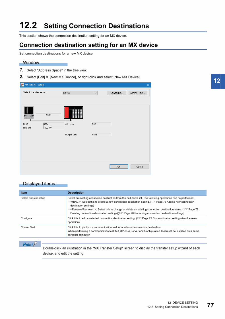
12 DEVICE SETTING12.2 Setting Connection Destinations 77
12
12.2 Setting Connection DestinationsThis section shows the connection destination setting for an MX device.
Connection destination setting for an MX deviceSet connection destinations for a new MX device.
Window
1. Select "Address Space" in the tree view.
2. Select [Edit] [New MX Device], or right-click and select [New MX Device].
Displayed items
Double-click an illustration in the "MX Transfer Setup" screen to display the transfer setup wizard of each
device, and edit the setting.
Item Description
Select transfer setup Select an existing connection destination from the pull-down list. The following operations can be performed.
• <New...>: Select this to create a new connection destination setting. (Page 78 Adding new connection
destination settings)
• <Rename/Remove...>: Select this to change or delete an existing connection destination name. (Page 78
Deleting connection destination settings)(Page 78 Renaming connection destination settings)
Configure Click this to edit a selected connection destination setting. (Page 79 Communication setting wizard screen
operation)
Comm. Test Click this to perform a communication test for a selected connection destination.
When performing a communication test, MX OPC UA Server and Configuration Tool must be installed on a same
personal computer.

7812 DEVICE SETTING12.2 Setting Connection Destinations
Precautions
If performing Ethernet communication, serial communication, or USB communication at the same time between MX OPC UA
Server started as a service and another MELSOFT product, a timeout error occurs.
When communicating with one device at the same time, perform any of the following:
• Communicate via different connection routes.
• Start MX OPC UA Server in Windows process.
• Start another MELSOFT product with the administrator authority.
When connecting MX OPC UA Server started as a service to a device via a CC-Link network interface board, a
communication test cannot be performed.
Adding new connection destination settingsAdd a new connection destination.
Operating procedure
1. Select <New...> from the pull-down list of "Select transfer setup" in the "MX Transfer Setup" screen.
2. Set the name of a new connection destination, select the setting of a copy source, and click the [OK] button.
Precautions
Up to 32 connection destinations can be set. If it is exceeded, delete a connection destination.
Deleting connection destination settingsDelete a connection destination.
Operating procedure
1. Select <Rename/Remove...> from the pull-down list of "Select transfer setup" in the "MX Transfer Setup" screen.
2. Select a connection destination to delete, and click the [Remove] button.
Renaming connection destination settingsRename a connection destination.
Operating procedure
1. Select <Rename/Remove...> from the pull-down list of "Select transfer setup" in the "MX Transfer Setup" screen.
2. Select a connection destination to rename, and click the [Rename] button.
3. Enter a new name, and press the key.
Item Description
Name Set the name of a new connection destination.
Copy Settings from Select a setting to apply to a new connection destination. When not using the setting of a copy source, select
<Default>.
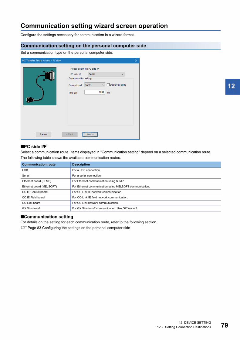
12 DEVICE SETTING12.2 Setting Connection Destinations 79
12
Communication setting wizard screen operationConfigure the settings necessary for communication in a wizard format.
Communication setting on the personal computer sideSet a communication type on the personal computer side.
■PC side I/FSelect a communication route. Items displayed in "Communication setting" depend on a selected communication route.
The following table shows the available communication routes.
■Communication settingFor details on the setting for each communication route, refer to the following section.
Page 83 Configuring the settings on the personal computer side
Communication route Description
USB For a USB connection.
Serial For a serial connection.
Ethernet board (SLMP) For Ethernet communication using SLMP.
Ethernet board (MELSOFT) For Ethernet communication using MELSOFT communication.
CC IE Control board For CC-Link IE network communication.
CC IE Field board For CC-Link IE field network communication.
CC-Link board For CC-Link network communication.
GX Simulator2 For GX Simulator2 communication. Use GX Works2.

8012 DEVICE SETTING12.2 Setting Connection Destinations
Communication setting on the connection destination device sideSet a communication type on the connection destination device side.
■PLC side I/FSelect a communication module on the connection destination device side. Items displayed in "Communication setting"
depend on a selected communication module.
The following shows the available communication modules.
• CPU module
• C24 module
• FX extended port
• Ethernet module
■Communication settingFor details on the setting for each communication module, refer to the following section.
Page 95 Configuring the settings on the connection destination device side

12 DEVICE SETTING12.2 Setting Connection Destinations 81
12
Network station number type settingSet a station number type or a CPU type of a network.
For details on each item, refer to the following section.
Page 108 Network station number type setting
Station number type - other station settingSet items in "Other station setting" when selecting "Other station" for "Station type".
For details on each item, refer to the following section.
Page 123 Station number type - other station setting

8212 DEVICE SETTING12.2 Setting Connection Destinations
Entering a commentEnter a comment for a set connection arbitrarily.
Click the [Finish] button to close the "MX Transfer Setup Wizard" screen.
Precautions
Communication settings that can be selected in the "MX Transfer Setup Wizard" screen are not all supported by MX OPC UA
Server.
If an unsupported communication route or device is selected, a warning message appears and the setting screen appears
again.
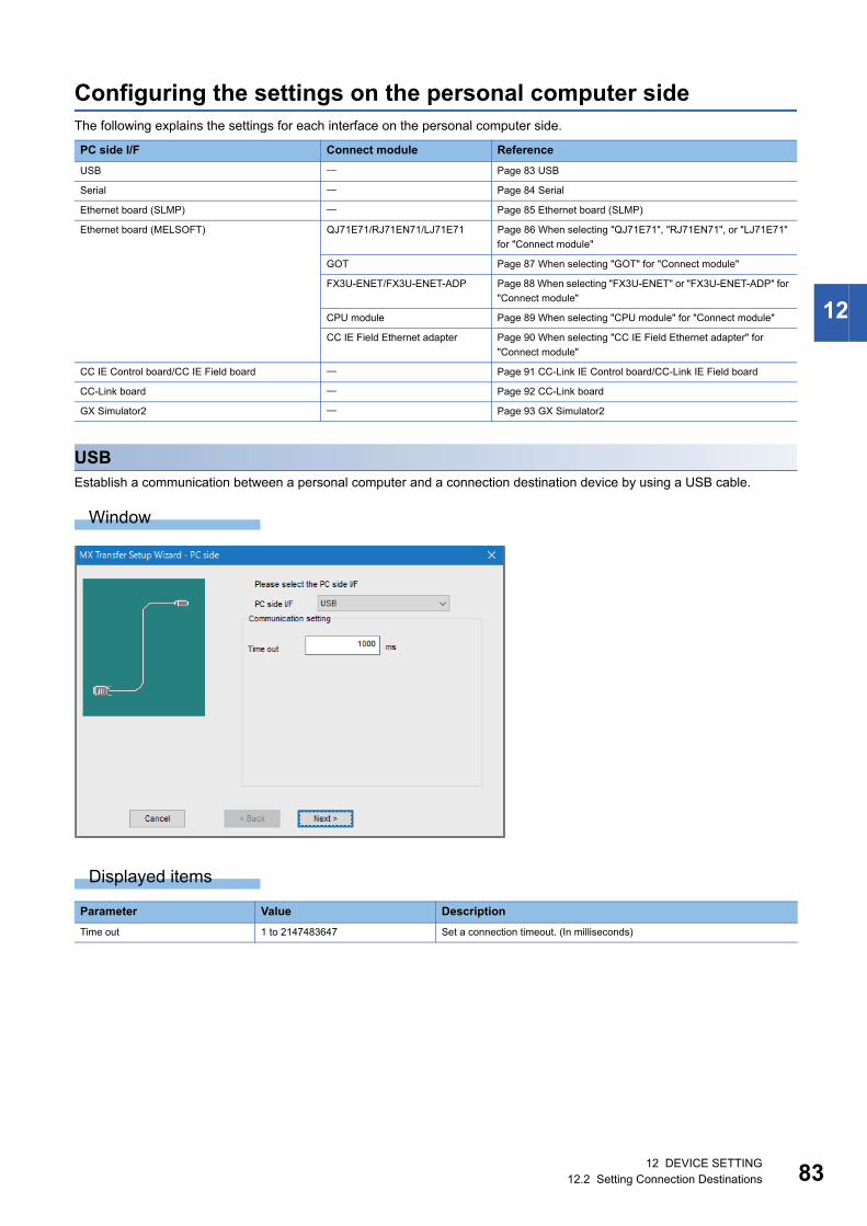
12 DEVICE SETTING12.2 Setting Connection Destinations 83
12
Configuring the settings on the personal computer sideThe following explains the settings for each interface on the personal computer side.
USBEstablish a communication between a personal computer and a connection destination device by using a USB cable.
Window
Displayed items
PC side I/F Connect module Reference
USB Page 83 USB
Serial Page 84 Serial
Ethernet board (SLMP) Page 85 Ethernet board (SLMP)
Ethernet board (MELSOFT) QJ71E71/RJ71EN71/LJ71E71 Page 86 When selecting "QJ71E71", "RJ71EN71", or "LJ71E71"
for "Connect module"
GOT Page 87 When selecting "GOT" for "Connect module"
FX3U-ENET/FX3U-ENET-ADP Page 88 When selecting "FX3U-ENET" or "FX3U-ENET-ADP" for
"Connect module"
CPU module Page 89 When selecting "CPU module" for "Connect module"
CC IE Field Ethernet adapter Page 90 When selecting "CC IE Field Ethernet adapter" for
"Connect module"
CC IE Control board/CC IE Field board Page 91 CC-Link IE Control board/CC-Link IE Field board
CC-Link board Page 92 CC-Link board
GX Simulator2 Page 93 GX Simulator2
Parameter Value Description
Time out 1 to 2147483647 Set a connection timeout. (In milliseconds)

8412 DEVICE SETTING12.2 Setting Connection Destinations
SerialEstablish a communication between a personal computer and a connection destination device by using an RS-232 cable.
Window
Displayed items
Parameter Value Description
Connect port When unselecting "Display all ports": COM1 to COMn
When selecting "Display all ports": COM1 to COM256
Select a port to use from the list of COM ports.
Display all ports Select this to display all available COM ports.
Unselect this to display only COM ports that are actually available.
Time out 1 to 2147483647 Set a connection timeout. (In milliseconds)
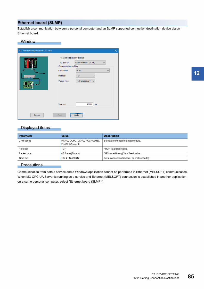
12 DEVICE SETTING12.2 Setting Connection Destinations 85
12
Ethernet board (SLMP)Establish a communication between a personal computer and an SLMP supported connection destination device via an
Ethernet board.
Window
Displayed items
Precautions
Communication from both a service and a Windows application cannot be performed in Ethernet (MELSOFT) communication.
When MX OPC UA Server is running as a service and Ethernet (MELSOFT) connection is established in another application
on a same personal computer, select "Ethernet board (SLMP)".
Parameter Value Description
CPU series RCPU, QCPU, LCPU, NCCPU(M8),
EcoWebServerIII
Select a connection target module.
Protocol TCP "TCP" is a fixed value.
Packet type 4E frame(Binary) "4E frame(Binary)" is a fixed value.
Time out 1 to 2147483647 Set a connection timeout. (In milliseconds)

8612 DEVICE SETTING12.2 Setting Connection Destinations
Ethernet board (MELSOFT)Establish a communication between a personal computer and a connection destination device via an Ethernet board.
Setting items depend on a module type selected in "Connect module".
■When selecting "QJ71E71", "RJ71EN71", or "LJ71E71" for "Connect module"
Window
Displayed items
*1 Appears only when selecting "UDP" for "Protocol".
Parameter Value Description
Connect module QJ71E71, RJ71EN71, LJ71E71 Select the type of a connection destination Ethernet module.
Protocol UDP, TCP Select a communication protocol.
Network No 1 to 239 Set the network number of an Ethernet module.
Station No 1 to 64 Set a station number for an interface on the personal computer.
It needs to be unique within a network set for "Network No".
Port No.*1 1025 to 65535 Set an unused UDP port number on the personal computer for data sent by
the connection destination device.
Do not use numbers less than 1025.
Time out 1 to 2147483647 Set a connection timeout. (In milliseconds)

12 DEVICE SETTING12.2 Setting Connection Destinations 87
12
■When selecting "GOT" for "Connect module"
Window
Displayed items
Parameter Value Description
Connect module GOT Select the type of a connection destination Ethernet module.
Port No. 1025 to 65535 Set an unused UDP port number on the personal computer for data sent by
the connection destination device.
Do not use numbers less than 1025.
Time out 1 to 2147483647 Set a connection timeout. (In milliseconds)
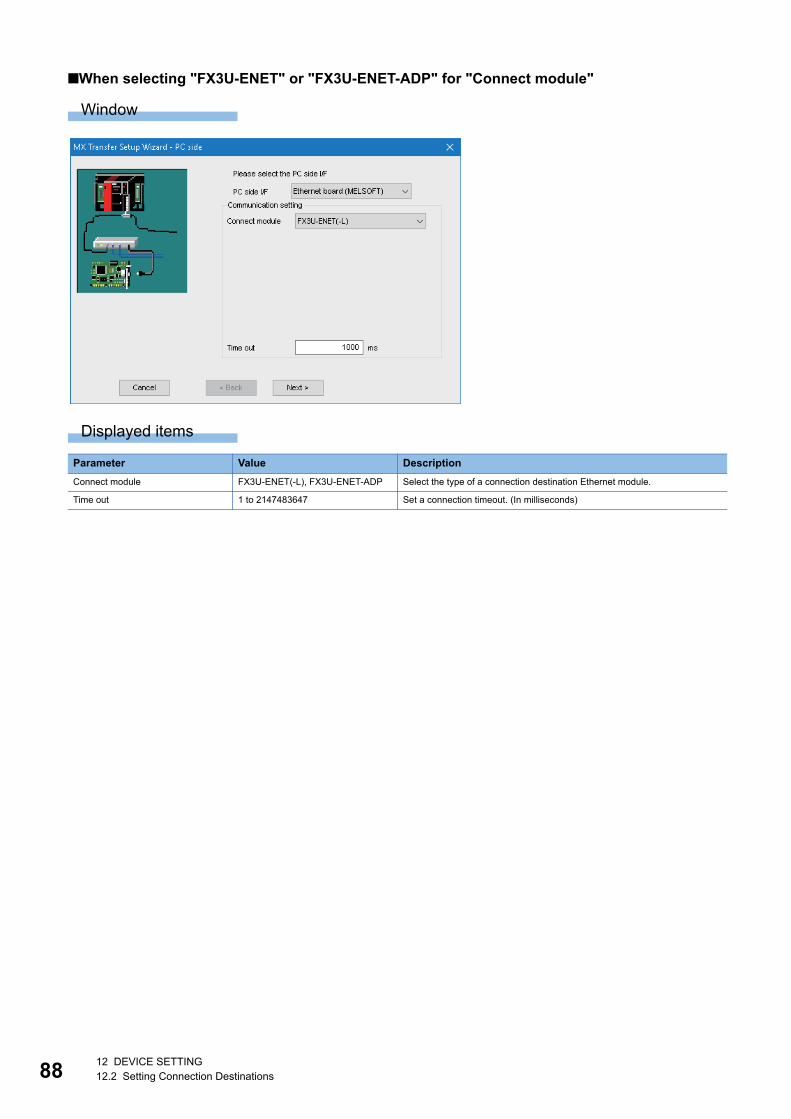
8812 DEVICE SETTING12.2 Setting Connection Destinations
■When selecting "FX3U-ENET" or "FX3U-ENET-ADP" for "Connect module"
Window
Displayed items
Parameter Value Description
Connect module FX3U-ENET(-L), FX3U-ENET-ADP Select the type of a connection destination Ethernet module.
Time out 1 to 2147483647 Set a connection timeout. (In milliseconds)
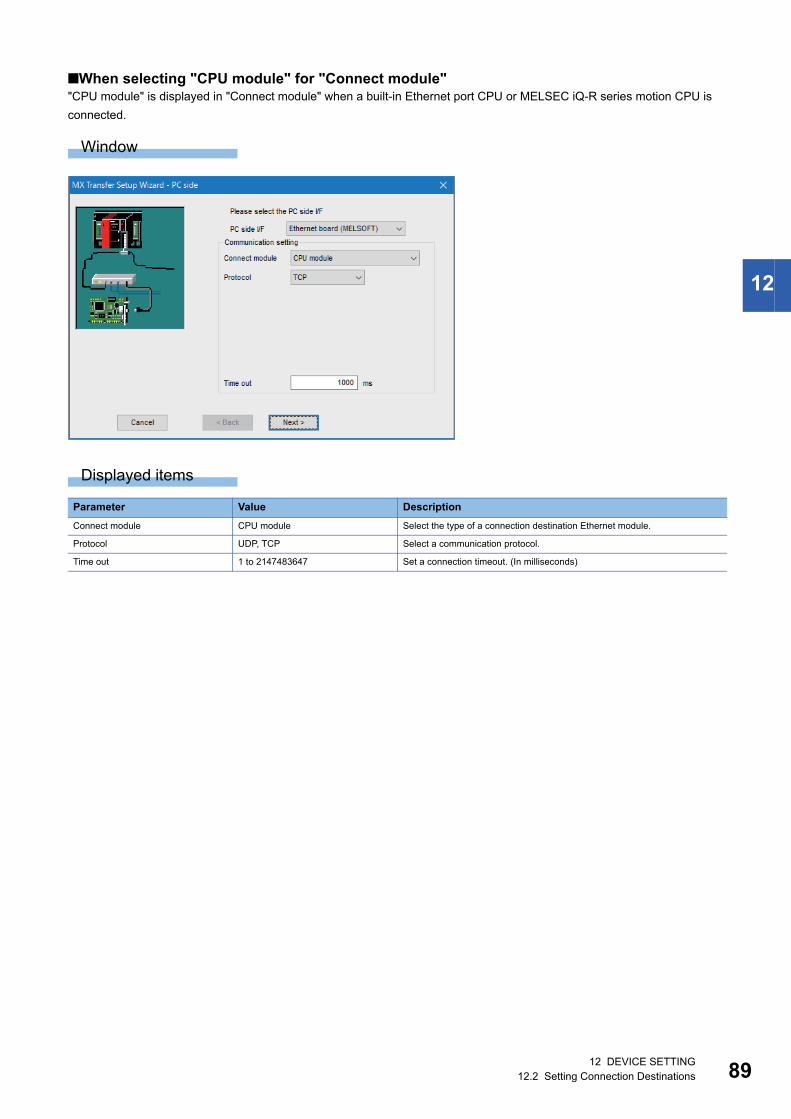
12 DEVICE SETTING12.2 Setting Connection Destinations 89
12
■When selecting "CPU module" for "Connect module""CPU module" is displayed in "Connect module" when a built-in Ethernet port CPU or MELSEC iQ-R series motion CPU is
connected.
Window
Displayed items
Parameter Value Description
Connect module CPU module Select the type of a connection destination Ethernet module.
Protocol UDP, TCP Select a communication protocol.
Time out 1 to 2147483647 Set a connection timeout. (In milliseconds)

9012 DEVICE SETTING12.2 Setting Connection Destinations
■When selecting "CC IE Field Ethernet adapter" for "Connect module"
Window
Displayed items
Precautions
■When connecting to the same E71 module from multiple MELSOFT applications • Set "UDP" for "Protocol" in the "Communication Setting Wizard" screen.
• Set the E71 switch (SW2) to OFF.
The following restrictions apply when connecting to the same E71 module at the same time from multiple personal computers
which use TCP or IP protocol.
• When using a Q series-compatible E71 module (except for QJ71E71-100), use a module with a serial number whose first
five digits are '02122' and function version B or later.
• In a GX Works3 project or GX Works2 project, select "MELSOFT Connection" for the open setting of an Ethernet module
parameter.
■When connecting to a CPU module via EthernetIt cannot be executed until a programmable controller CPU is RUN once.
Parameter Value Description
Connect module CC IE Field Ethernet adapter Select the type of a connection destination Ethernet module.
Protocol UDP, TCP Select a communication protocol.
Time out 1 to 2147483647 Set a connection timeout. (In milliseconds)
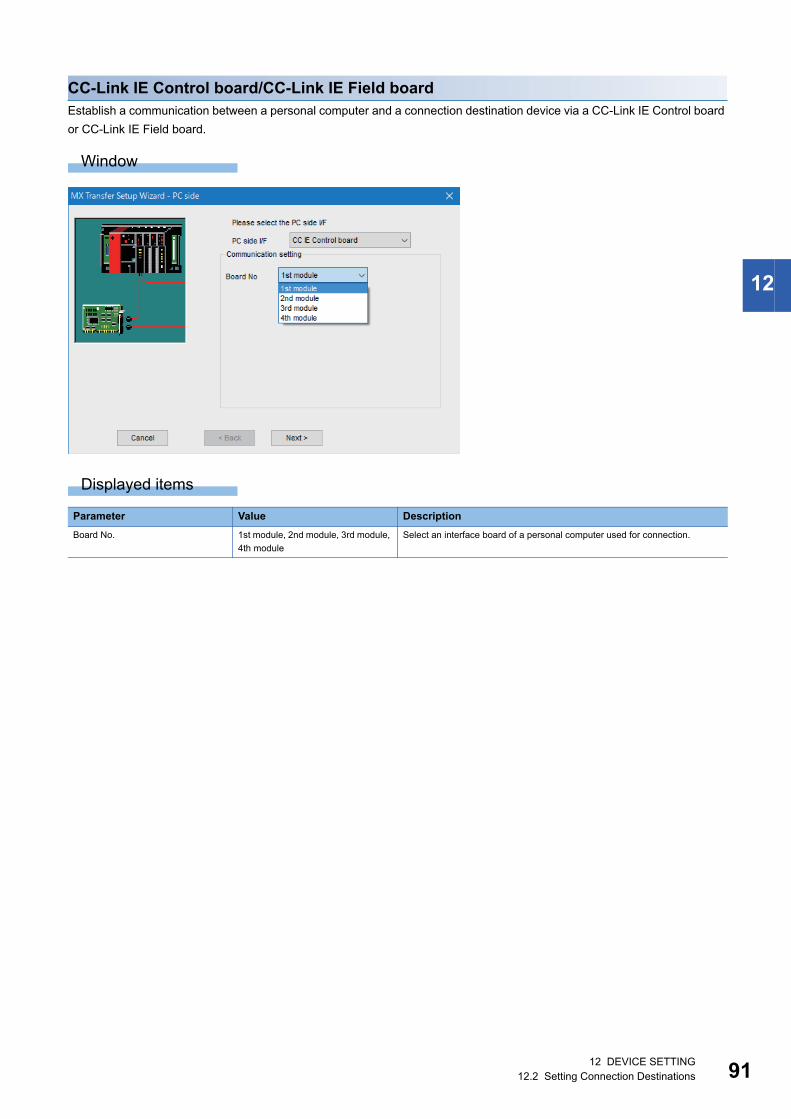
12 DEVICE SETTING12.2 Setting Connection Destinations 91
12
CC-Link IE Control board/CC-Link IE Field boardEstablish a communication between a personal computer and a connection destination device via a CC-Link IE Control board
or CC-Link IE Field board.
Window
Displayed items
Parameter Value Description
Board No. 1st module, 2nd module, 3rd module,
4th module
Select an interface board of a personal computer used for connection.

9212 DEVICE SETTING12.2 Setting Connection Destinations
CC-Link boardEstablish a communication between a personal computer and a connection destination device via a CC-Link network
interface board.
Window
Displayed items
Precautions
For CC-Link communication or CC-Link G4 communication (using AJ65BT-G4), use a CC-Link master/local module whose
software version is N or later.
Otherwise, the module does not operate normally.
Parameter Value Description
Board No. 1st module, 2nd module, 3rd module,
4th module
Select an interface board of a personal computer used for connection.

12 DEVICE SETTING12.2 Setting Connection Destinations 93
12
GX Simulator2Connect to GX Simulator2 running on a same computer.
Window
Displayed items
Precautions
Check that GX Simulator2 is running before connecting.
Parameter Value Description
Target Simulator • None
• Simulator A
• Simulator B
• Simulator C
• Simulator D
Select a simulator to connect.
Click the [Browse] button to display the "Find GX Simulator2 Runtime" screen.
Information on the currently running GX Simulator2 is displayed. Select GX Simulator2 to
connect.
CPU Series QCPU(Q mode), LCPU,
FXCPU
Select a CPU series to simulate.

9412 DEVICE SETTING12.2 Setting Connection Destinations
■"Find GX Simulator2 Runtime" screenSearch GX Simulator2 to connect.
Window
Displayed items
To update the list of GX Simulator2, click the [Update] button.
Item Description
Target A name of GX Simulator2 in Configuration Tool is displayed.
Project Name A file name of a GX Works2 project is displayed.
CPU Series A CPU series set in a GX Works2 project is displayed.
CPU Type A CPU type set in a GX Works2 project is displayed.
Workspace For a GX Works2 project in a workspace format, a workspace name is displayed.
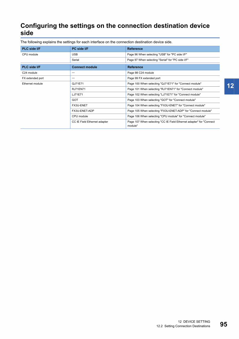
12 DEVICE SETTING12.2 Setting Connection Destinations 95
12
Configuring the settings on the connection destination device sideThe following explains the settings for each interface on the connection destination device side.
PLC side I/F PC side I/F Reference
CPU module USB Page 96 When selecting "USB" for "PC side I/F"
Serial Page 97 When selecting "Serial" for "PC side I/F"
PLC side I/F Connect module Reference
C24 module Page 98 C24 module
FX extended port Page 99 FX extended port
Ethernet module QJ71E71 Page 100 When selecting "QJ71E71" for "Connect module"
RJ71EN71 Page 101 When selecting "RJ71EN71" for "Connect module"
LJ71E71 Page 102 When selecting "LJ71E71" for "Connect module"
GOT Page 103 When selecting "GOT" for "Connect module"
FX3U-ENET Page 104 When selecting "FX3U-ENET" for "Connect module"
FX3U-ENET-ADP Page 105 When selecting "FX3U-ENET-ADP" for "Connect module"
CPU module Page 106 When selecting "CPU module" for "Connect module"
CC IE Field Ethernet adapter Page 107 When selecting "CC IE Field Ethernet adapter" for "Connect
module"
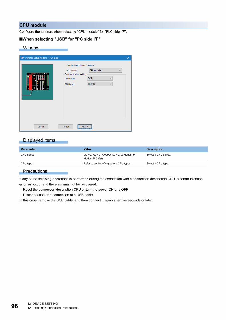
9612 DEVICE SETTING12.2 Setting Connection Destinations
CPU moduleConfigure the settings when selecting "CPU module" for "PLC side I/F".
■When selecting "USB" for "PC side I/F"
Window
Displayed items
Precautions
If any of the following operations is performed during the connection with a connection destination CPU, a communication
error will occur and the error may not be recovered.
• Reset the connection destination CPU or turn the power ON and OFF
• Disconnection or reconnection of a USB cable
In this case, remove the USB cable, and then connect it again after five seconds or later.
Parameter Value Description
CPU series QCPU, RCPU, FXCPU, LCPU, Q Motion, R
Motion, R Safety
Select a CPU series.
CPU type Refer to the list of supported CPU types. Select a CPU type.

12 DEVICE SETTING12.2 Setting Connection Destinations 97
12
■When selecting "Serial" for "PC side I/F"
Window
Displayed items
Precautions
■Considerations when CPU type is Q00J, Q00, or Q01CPUIf a selected transmission speed is different from one set in a personal computer, 9600 bps will be a fixed value for a
transmission speed.
To increase the transmission speed, match the setting on the personal computer side to that on the CPU side.
■Supported transmission speedFor the transmission speed of QCPUs, 9600 bps, 19200 bps, 38400 bps, 57600 bps, or 115200bps can be set.
9600 bps is a fixed value for a transmission speed of a motion controller CPU. (19200 bps may be set for A2USHCPU-S1.)
Parameter Value Description
CPU series QCPU, FXCPU, LCPU, Q Motion Select a CPU series.
CPU type Refer to the list of supported CPU
types.
Select a CPU type.
Transmission speed 9600 to 115200 Select a baud rate for serial communication.
Control DTR Control, RTS Control, DTR and
RTS Control, DTR or RTS Control
Select a handshake signal.
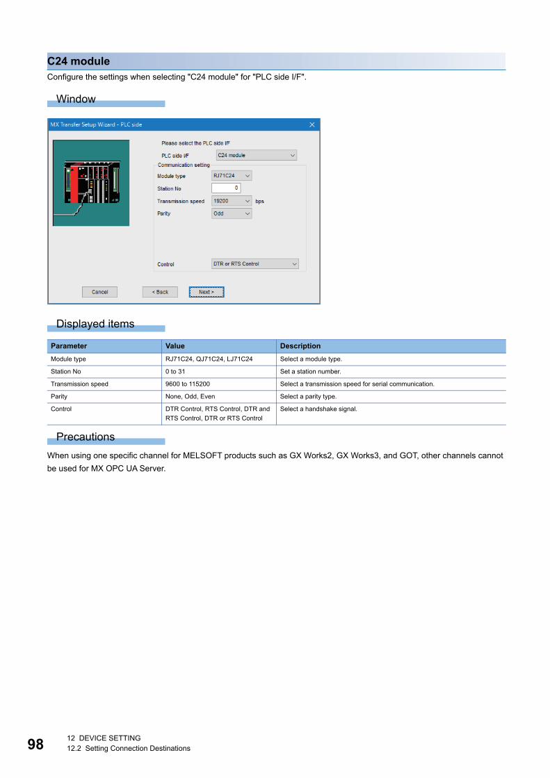
9812 DEVICE SETTING12.2 Setting Connection Destinations
C24 moduleConfigure the settings when selecting "C24 module" for "PLC side I/F".
Window
Displayed items
Precautions
When using one specific channel for MELSOFT products such as GX Works2, GX Works3, and GOT, other channels cannot
be used for MX OPC UA Server.
Parameter Value Description
Module type RJ71C24, QJ71C24, LJ71C24 Select a module type.
Station No 0 to 31 Set a station number.
Transmission speed 9600 to 115200 Select a transmission speed for serial communication.
Parity None, Odd, Even Select a parity type.
Control DTR Control, RTS Control, DTR and
RTS Control, DTR or RTS Control
Select a handshake signal.

12 DEVICE SETTING12.2 Setting Connection Destinations 99
12
FX extended portConfigure the settings when selecting "FX extended port" for "PLC side I/F".
Window
Displayed items
Parameter Value Description
Module type FX485BD/ADP Select a module type.
Station No 0 to 15 Set a station number.
Transmission speed 300 to 19200 Select a transmission speed for serial communication.
Parity None, Odd, Even Select a parity type.
Data bit 7, 8 Select the number of data bits.
Stop bit 1, 2 Select the number of stop bits.
Sum check Existence, None Select this to enable or disable sum check.
Control DTR Control, RTS Control, DTR and RTS
Control, DTR or RTS Control
Select a handshake signal.
Transmission 1 to 65535 Set the multiple number of 10 milliseconds as a communication waiting time.
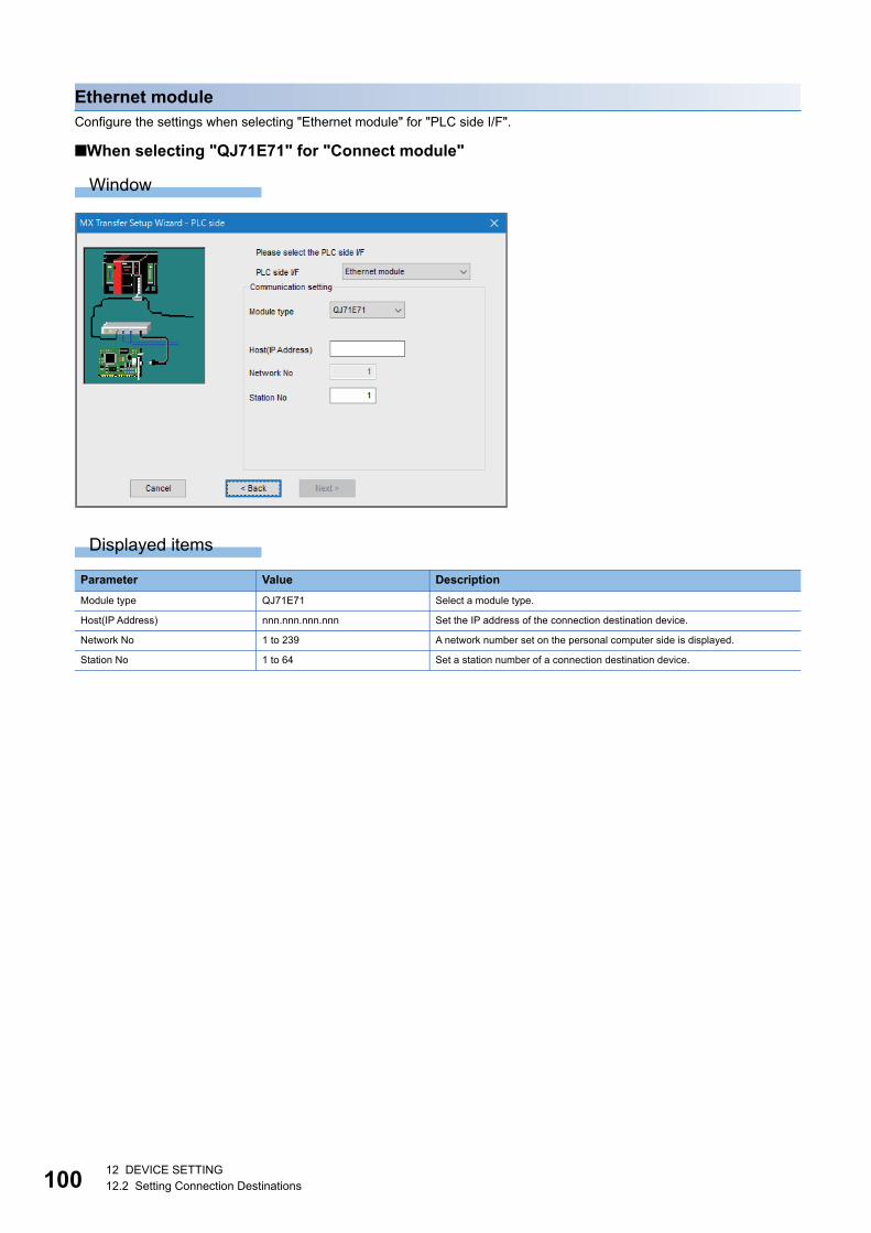
10012 DEVICE SETTING12.2 Setting Connection Destinations
Ethernet moduleConfigure the settings when selecting "Ethernet module" for "PLC side I/F".
■When selecting "QJ71E71" for "Connect module"
Window
Displayed items
Parameter Value Description
Module type QJ71E71 Select a module type.
Host(IP Address) nnn.nnn.nnn.nnn Set the IP address of the connection destination device.
Network No 1 to 239 A network number set on the personal computer side is displayed.
Station No 1 to 64 Set a station number of a connection destination device.

12 DEVICE SETTING12.2 Setting Connection Destinations 101
12
■When selecting "RJ71EN71" for "Connect module"
Window
Displayed items
*1 Appears only when selecting "UDP" for "Protocol" in the personal computer side setting.
Parameter Value Description
Module type RJ71EN71 Select a module type.
Ethernet port direct connection*1 Select this to connect a personal computer and an Ethernet port of a connection
destination device with a single cable.
Host(IP Address) nnn.nnn.nnn.nnn Set the IP address of the connection destination device.
Network No 1 to 239 A network number set on the personal computer side is displayed.
Station No 1 to 120 Set a station number of a connection destination device.
Adapter*1 Ethernet adapter installed in a
personal computer
Select an Ethernet adapter to use.
The IP address is also displayed for confirmation.IP Address*1

10212 DEVICE SETTING12.2 Setting Connection Destinations
■When selecting "LJ71E71" for "Connect module"
Window
Displayed items
Parameter Value Description
Module type LJ71E71 Select a module type.
Host(IP Address) nnn.nnn.nnn.nnn Set the IP address of the connection destination device.
Network No 1 to 239 A network number set on the personal computer side is displayed.
Station No 1 to 64 Set a station number of a connection destination device.
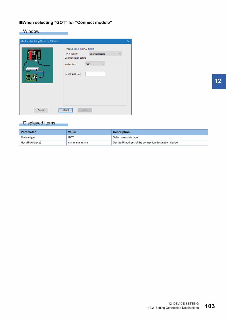
12 DEVICE SETTING12.2 Setting Connection Destinations 103
12
■When selecting "GOT" for "Connect module"
Window
Displayed items
Parameter Value Description
Module type GOT Select a module type.
Host(IP Address) nnn.nnn.nnn.nnn Set the IP address of the connection destination device.

10412 DEVICE SETTING12.2 Setting Connection Destinations
■When selecting "FX3U-ENET" for "Connect module"
Window
Displayed items
Parameter Value Description
Module type FX3U-ENET(-L) Select a module type.
Host(IP Address) nnn.nnn.nnn.nnn Set the IP address of the connection destination device.

12 DEVICE SETTING12.2 Setting Connection Destinations 105
12
■When selecting "FX3U-ENET-ADP" for "Connect module"
Window
Displayed items
Parameter Value Description
Ethernet port direct connection Select this to connect a personal computer and an Ethernet port of a connection
destination device with a single cable.
Host(IP Address) nnn.nnn.nnn.nnn Set the IP address of the connection destination device.
Find CPU (Built-in Ethernet port) on
network
Click this to search for a CPU module (built-in Ethernet port) on a network.
Select a searched CPU module, and its IP address is set in "Host(IP Address).
Adapter Ethernet adapter installed in a
personal computer
Select an Ethernet adapter to use.
The IP address is also displayed for confirmation.IP Address

10612 DEVICE SETTING12.2 Setting Connection Destinations
■When selecting "CPU module" for "Connect module"
Window
Displayed items
*1 Appears only when selecting "UDP" for "Protocol" in the personal computer side setting.
Precautions
• Connecting to a C Controller module (Q12DCCPU-V)
Q12DCCPU-Vs on the network are not displayed by using the "Find CPU (Built-in Ethernet port) on network" function.
Parameter Value Description
Ethernet port direct connection*1 Select this to connect a personal computer and an Ethernet port of a connection
destination device with a single cable.
Host(IP Address) nnn.nnn.nnn.nnn Set the IP address of the connection destination device.
Find CPU (Built-in Ethernet port) on
network
Click this to search for a CPU module (built-in Ethernet port) on a network.
Select a searched CPU module, and its IP address is set in "Host(IP Address).
Adapter*1 Ethernet adapter installed in a
personal computer
Select an Ethernet adapter to use.
The IP address is also displayed for confirmation.IP Address*1

12 DEVICE SETTING12.2 Setting Connection Destinations 107
12
■When selecting "CC IE Field Ethernet adapter" for "Connect module"
Window
Displayed items
*1 Appears only when selecting "UDP" for "Protocol" in the personal computer side setting.
Parameter Value Description
Ethernet port direct connection*1 Select this to connect a personal computer and an Ethernet port of a connection
destination device with a single cable.
Host(IP Address) nnn.nnn.nnn.nnn Set the IP address of the connection destination device.
Adapter*1 Ethernet adapter installed in a
personal computer
Select an Ethernet adapter to use.
The IP address is also displayed for confirmation.IP Address*1

10812 DEVICE SETTING12.2 Setting Connection Destinations
Network station number type settingThe following explains the settings for each network.
PC side I/F PLC side I/F Network (other station setting)
Reference
USB CPU module Host station Page 109 Connection to a CPU module on the host
station
Other station Page 110 Connection to a CPU module on another
station
Serial CPU module Host station Page 109 Connection to a CPU module on the host
station
Other station Page 110 Connection to a CPU module on another
station
C24 module Host station Page 111 Connection to a C24 module on the host station
Other station Page 112 Connection to a C24 module on another station
FX extended port Host station Page 113 Connection to an FX extended port on the host
station
Other station Page 114 Connection to an FX extended port on another
station
Ethernet board (SLMP) Ethernet module N/A
Ethernet board (MELSOFT) Ethernet module Host station Page 115 Connection to an Ethernet module on the host
station
Other station Page 116 Connection to an Ethernet module on another
station
CPU module Host station Page 115 Connection to an Ethernet module on the host
station
Other station Page 116 Connection to an Ethernet module on another
station
FX3U-ENET-ADP Host station Page 113 Connection to an FX extended port on the host
station
CC IE Field Ethernet adapter Other station(Single) Page 118 Connection to another station (single network)
Other station(Coexistence) Page 117 Connection to a CC IE Field Ethernet adapter
module
CC IE Control board N/A Host station
Other station(Single) Page 118 Connection to another station (single network)
Other station(Coexistence) Page 119 Connection (CC-Link IE Control Network) to
another station (coexistence)
CC IE Field board N/A Host station
Other station(Single) Page 118 Connection to another station (single network)
Other station(Coexistence) Page 120 Connection (CC-Link IE Field Network) to
another station (coexistence)
CC-Link board N/A Host station Page 121 Connection to a CPU module on the host
station (CC-Link)
Other station(Single) Page 118 Connection to another station (single network)
Other station(Coexistence) Page 122 Connection to a CPU module on another
station (CC-Link)
GX Simulator2 N/A N/A

12 DEVICE SETTING12.2 Setting Connection Destinations 109
12
Connection to a CPU module on the host station
Window
Ex.
Displayed items
Parameter Value Description
Station type Host station Select a station number type.
Multiple CPU None, No.1, No.2, No.3, No.4 When a multiple CPU system is included in a connection destination device,
select a target CPU number.
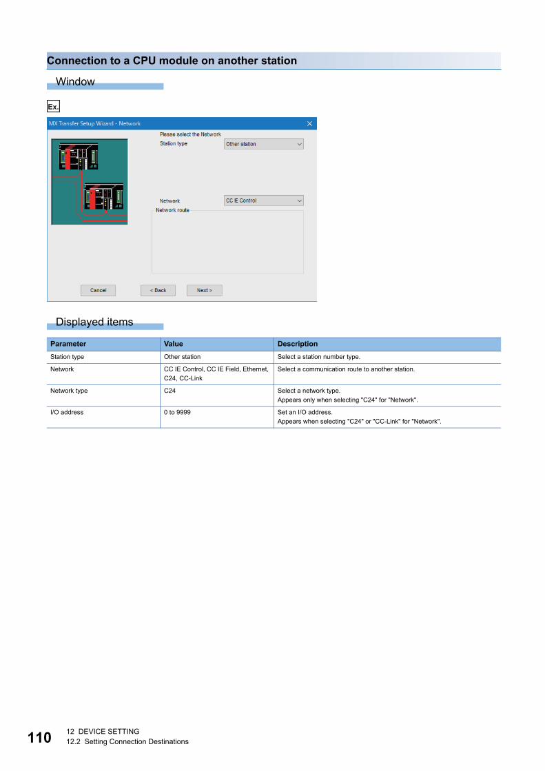
11012 DEVICE SETTING12.2 Setting Connection Destinations
Connection to a CPU module on another station
Window
Ex.
Displayed items
Parameter Value Description
Station type Other station Select a station number type.
Network CC IE Control, CC IE Field, Ethernet,
C24, CC-Link
Select a communication route to another station.
Network type C24 Select a network type.
Appears only when selecting "C24" for "Network".
I/O address 0 to 9999 Set an I/O address.
Appears when selecting "C24" or "CC-Link" for "Network".

12 DEVICE SETTING12.2 Setting Connection Destinations 111
12
Connection to a C24 module on the host station
Window
Ex.
Displayed items
Parameter Value Description
Station type Host station Select a station number type.
CPU series It depends on a module type on the
connection destination device side.
Select a CPU series.
CPU type Refer to the list of supported CPU
types.
Select a CPU type.
Operation Mode None, Redundant Select an operation mode.
Depending on the CPU series or CPU type, the item may not appear.
Multiple CPU None, No.1, No.2, No.3, No.4 When a multiple CPU system is included in a connection destination device,
select a target CPU number.
Depending on the CPU series or CPU type, the item may not appear.
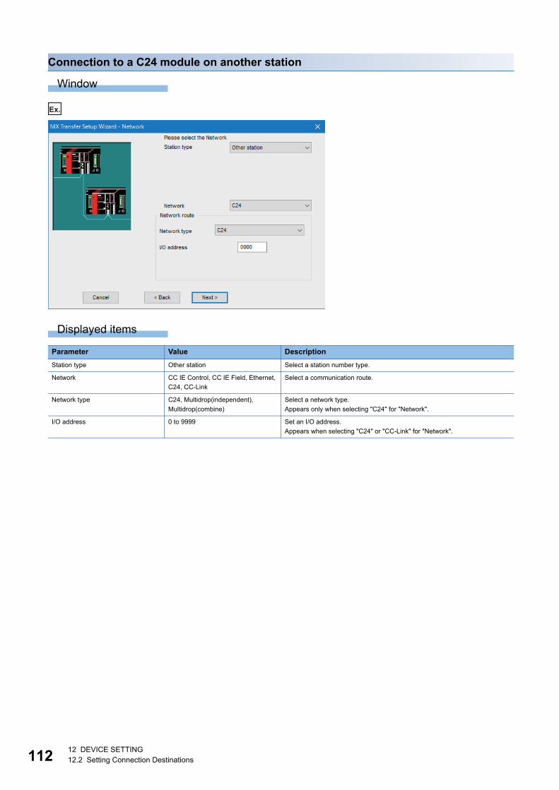
11212 DEVICE SETTING12.2 Setting Connection Destinations
Connection to a C24 module on another station
Window
Ex.
Displayed items
Parameter Value Description
Station type Other station Select a station number type.
Network CC IE Control, CC IE Field, Ethernet,
C24, CC-Link
Select a communication route.
Network type C24, Multidrop(independent),
Multidrop(combine)
Select a network type.
Appears only when selecting "C24" for "Network".
I/O address 0 to 9999 Set an I/O address.
Appears when selecting "C24" or "CC-Link" for "Network".

12 DEVICE SETTING12.2 Setting Connection Destinations 113
12
Connection to an FX extended port on the host station
Window
Ex.
Displayed items
Parameter Value Description
Station type Host station Select a station number type.
Connect CPU series FXCPU Select a CPU series.
CPU type Refer to the list of supported CPU
types.
Select a CPU type.

11412 DEVICE SETTING12.2 Setting Connection Destinations
Connection to an FX extended port on another station
Window
Ex.
Displayed items
Parameter Value Description
Station type Other station Select a station number type.
Network type Multidrop Select a network type.
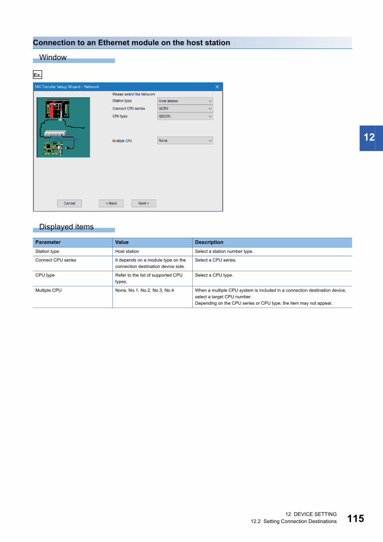
12 DEVICE SETTING12.2 Setting Connection Destinations 115
12
Connection to an Ethernet module on the host station
Window
Ex.
Displayed items
Parameter Value Description
Station type Host station Select a station number type.
Connect CPU series It depends on a module type on the
connection destination device side.
Select a CPU series.
CPU type Refer to the list of supported CPU
types.
Select a CPU type.
Multiple CPU None, No.1, No.2, No.3, No.4 When a multiple CPU system is included in a connection destination device,
select a target CPU number.
Depending on the CPU series or CPU type, the item may not appear.

11612 DEVICE SETTING12.2 Setting Connection Destinations
Connection to an Ethernet module on another station
Window
Ex.
Displayed items
Parameter Value Description
Station type Other station Select a station number type.
Connect CPU series It depends on a module type on the
connection destination device side.
Select a CPU series.
Network CC IE Control, CC IE Field, Ethernet,
C24, CC-Link
Select a communication route.
Network type C24 Select a network type.
Appears only when selecting "C24" for "Network".
I/O address 0 to 9999 Set an I/O address.
Appears when selecting "C24" or "CC-Link" for "Network".

12 DEVICE SETTING12.2 Setting Connection Destinations 117
12
Connection to a CC IE Field Ethernet adapter module
Window
Ex.
Displayed items
Parameter Value Description
Station type Other station(Coexistence) Select a station number type.
Connect CPU series QCPU, LCPU Select a CPU series.
Connect CPU type Refer to the list of supported CPU
types.
Select a CPU type of a relay station.
Connect network No 1 to 239 Set a network number of a relay station.
Appears only when selecting "C24" for "Network".
Connect station No 0 to 120 Set a station number of a relay station.
Appears only when selecting "C24" for "Network".
Network CC IE Control, CC IE Field, Ethernet,
C24, CC-Link
Select a communication route.
Network type C24 Select a network type.
Appears only when selecting "C24" for "Network".
I/O address 0 to 9999 Set an I/O address.
Appears when selecting "C24" or "CC-Link" for "Network".

11812 DEVICE SETTING12.2 Setting Connection Destinations
Connection to another station (single network)
Window
Ex.
Displayed items
Parameter Value Description
Station type Other station(Single) Select a station number type.

12 DEVICE SETTING12.2 Setting Connection Destinations 119
12
Connection (CC-Link IE Control Network) to another station (coexistence)
Window
Ex.
Displayed items
Parameter Value Description
Station type Other station(Coexistence) Select a station number type.
Connect CPU series QCPU, RCPU, R Safety Select a CPU series.
Connect CPU type Refer to the list of supported CPU
types.
Select a CPU type of a relay station.
Network CC IE Control, Ethernet, C24, CC-
Link
Select a communication route.
Network type C24 Select a network type.
Appears only when selecting "C24" for "Network".
I/O address 0 to 9999 Set an I/O address.
Appears when selecting "C24" or "CC-Link" for "Network".
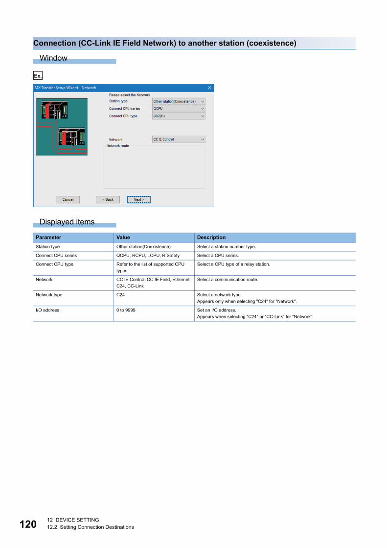
12012 DEVICE SETTING12.2 Setting Connection Destinations
Connection (CC-Link IE Field Network) to another station (coexistence)
Window
Ex.
Displayed items
Parameter Value Description
Station type Other station(Coexistence) Select a station number type.
Connect CPU series QCPU, RCPU, LCPU, R Safety Select a CPU series.
Connect CPU type Refer to the list of supported CPU
types.
Select a CPU type of a relay station.
Network CC IE Control, CC IE Field, Ethernet,
C24, CC-Link
Select a communication route.
Network type C24 Select a network type.
Appears only when selecting "C24" for "Network".
I/O address 0 to 9999 Set an I/O address.
Appears when selecting "C24" or "CC-Link" for "Network".

12 DEVICE SETTING12.2 Setting Connection Destinations 121
12
Connection to a CPU module on the host station (CC-Link)
Window
Ex.
Displayed items
When using an interface board for CC-Link connection, the screen differs from neither of serial and USB connection.
Parameter Value Description
Station type Host station Select a station number type.
Multiple CPU None, No.1, No.2, No.3, No.4 When a multiple CPU system is included in a connection destination device,
select a target CPU number.

12212 DEVICE SETTING12.2 Setting Connection Destinations
Connection to a CPU module on another station (CC-Link)
Window
Ex.
Displayed items
Parameter Value Description
Station type Other station(Coexistence) Select a station number type.
Connect CPU series QCPU, RCPU, R Safety Select a CPU series.
Connect CPU type Refer to the list of supported CPU
types.
Select a CPU type of a relay station.
Connect station No 0 to 64 Set a station number of a relay station.
Network CC IE Control, CC IE Field, Ethernet Select a communication route.

12 DEVICE SETTING12.2 Setting Connection Destinations 123
12
Station number type - other station settingSet the type of a connection destination device on another station and network address information.
Station in a same network as C24 or FX
Window
Ex.
Displayed items
Parameter Value Description
CPU series It depends on a setting on the
personal computer side or the
connection destination device side.
Select a CPU series.
CPU type Refer to the list of supported CPU
types.
Select a CPU type.
Station No 0 to 31 Set a station number of a connection destination device.
Operation Mode None, Redundant Select an operation mode.
Depending on the CPU series or CPU type, the item may not appear.
Multiple CPU None, No.1, No.2, No.3, No.4 When a multiple CPU system is included in a connection destination device,
select a target CPU number.
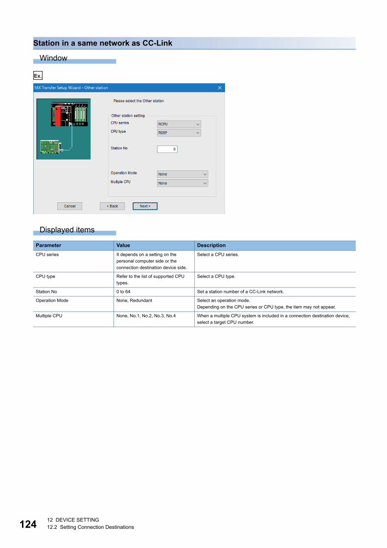
12412 DEVICE SETTING12.2 Setting Connection Destinations
Station in a same network as CC-Link
Window
Ex.
Displayed items
Parameter Value Description
CPU series It depends on a setting on the
personal computer side or the
connection destination device side.
Select a CPU series.
CPU type Refer to the list of supported CPU
types.
Select a CPU type.
Station No 0 to 64 Set a station number of a CC-Link network.
Operation Mode None, Redundant Select an operation mode.
Depending on the CPU series or CPU type, the item may not appear.
Multiple CPU None, No.1, No.2, No.3, No.4 When a multiple CPU system is included in a connection destination device,
select a target CPU number.

12 DEVICE SETTING12.2 Setting Connection Destinations 125
12
Station in a same or different network
Window
Ex.
Displayed items
Parameter Value Description
CPU series It depends on a setting on the
personal computer side or the
connection destination device side.
Select a CPU series.
CPU type Refer to the list of supported CPU
types.
Select a CPU type.
Network No 1 to 239 Set a network number of a connection destination device.
Station No 1 to 64 Set a station number of a connection destination device.
Operation Mode None, Redundant Select an operation mode.
Depending on the CPU series or CPU type, the item may not appear.
Multiple CPU None, No.1, No.2, No.3, No.4 When a multiple CPU system is included in a connection destination device,
select a target CPU number.
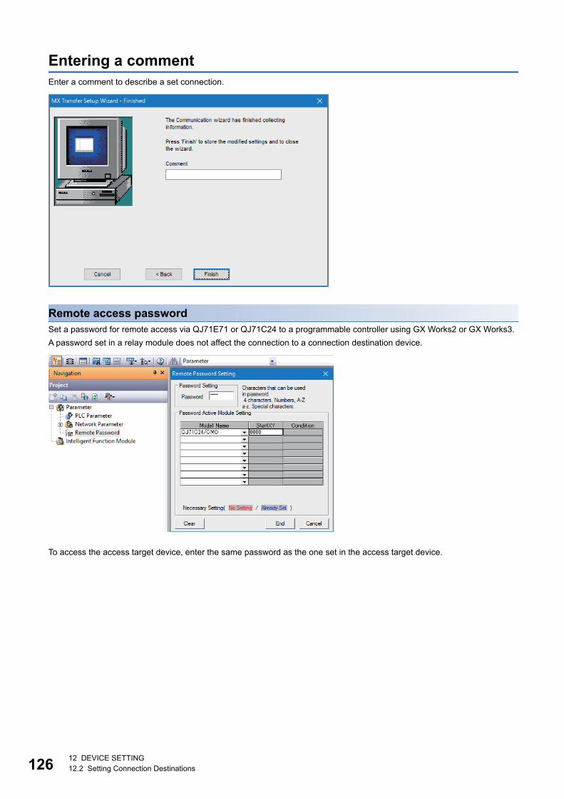
12612 DEVICE SETTING12.2 Setting Connection Destinations
Entering a commentEnter a comment to describe a set connection.
Remote access passwordSet a password for remote access via QJ71E71 or QJ71C24 to a programmable controller using GX Works2 or GX Works3.
A password set in a relay module does not affect the connection to a connection destination device.
To access the access target device, enter the same password as the one set in the access target device.
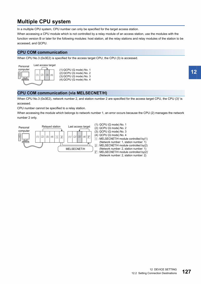
12 DEVICE SETTING12.2 Setting Connection Destinations 127
12
Multiple CPU systemIn a multiple CPU system, CPU number can only be specified for the target access station.
When accessing a CPU module which is not controlled by a relay module of an access station, use the modules with the
function version B or later for the following modules: host station, all the relay stations and relay modules of the station to be
accessed, and QCPU.
CPU COM communicationWhen CPU No.3 (0x3E2) is specified for the access target CPU, the CPU (3) is accessed.
CPU COM communication (via MELSECNET/H)When CPU No.3 (0x3E2), network number 2, and station number 2 are specified for the access target CPU, the CPU (3)' is
accessed.
CPU number cannot be specified to a relay station.
When accessing the module which belongs to network number 1, an error occurs because the CPU (2) manages the network
number 2 only.
(2) (4)
Last access targetPersonalcomputer (1):QCPU (Q mode) No. 1
(2):QCPU (Q mode) No. 2(3):QCPU (Q mode) No. 3(4):QCPU (Q mode) No. 4
(1) (3)
(3) (1)’ (4)’
Personalcomputer
Relayed station
MELSECNET/H
Last access target(1): QCPU (Q mode) No. 1(2): QCPU (Q mode) No. 2(3): QCPU (Q mode) No. 3(4): QCPU (Q mode) No. 4
: MELSECNET/H module controlled by(1) (Network number: 1, station number: 1): MELSECNET/H module controlled by(2) (Network number: 2, station number: 1): MELSECNET/H module controlled by(2)’ (Network number: 2, station number: 2)
(1) (2) (4) (2)’ (3)’
12812 DEVICE SETTING12.2 Setting Connection Destinations
Restrictions on C Controller module connectionIn the connection destination setting in Configuration Tool, C Controller modules, which do not support MX OPC Server UA,
are displayed.
The following shows the connection types supported by MX OPC Server UA.
• PC (USB) - C Controller module
• PC (Ethernet) - C Controller module
Do not set the following connection types since they are not supported by MX OPC Server UA.
• PC (Serial) - C Controller module
• PC (C24) - C Controller module
• PC (CC-Link) - C Controller module
• PC (CC-Link IE Control) - C Controller module
• PC (CC-Link IE Field) - C Controller module
13 TAG SETTING AND MONITORING13.1 Address Space (Tag) Setting 129
13
13 TAG SETTING AND MONITORING
This chapter explains the tag setting and monitoring.
13.1 Address Space (Tag) SettingThis section shows the setting of tags accessed from MX OPC UA Server.
Newly adding or editing MX device tagsThe following shows the procedure to newly add or edit an MX device tag.
New
Operating procedure
1. Select an MX device in the tree view.
Select a group when adding a tag to a group.
2. Select [Edit] [New Data Tag].
The "Tag Properties" screen appears.
3. Set each item in the "Tag Properties" screen. (Page 130 MX device tag screen setting)
4. Click the [Save] button.
The setting is saved, and an MX device tag appears in the list view.
Edit
Operating procedure
1. Double-click a tag in the list view.
The "Tag Properties" screen appears.
2. Set each item in the "Tag Properties" screen. (Page 130 MX device tag screen setting)
3. Click the [Save] button.
The setting is saved, and an MX device tag appears in the list view.

13013 TAG SETTING AND MONITORING13.1 Address Space (Tag) Setting
MX device tag screen setting
■Basic
Displayed items
*1 When selecting "Write", tag values cannot be read from an client application.In the list view, "NA" is displayed in the "Value" column, and "Bad" in the "Status" column.
*2 When using read-only devices (such as SA\*safety register), only "Read" can be selected.*3 When a number to be added already exists, the number is skipped and the next available number is added.
Item Description
Name Set the name of a tag. (Up to 50 characters)
Description Set the description of a tag. (Up to 128 characters)
Remark Set the note of a tag. (Up to 128 characters)
General Setup I/O Address Set the I/O address of an access target.
[Browse] button Click this to show the list of available devices. (Page 131 PLC device list screen)
Access Rights Select an access right.*1,*2
Data Type Select a data type.
When selecting an advanced type for "Data type" in the [Advanced] tab, the selected type
is displayed.
Data Polling Poll. Method Select a polling definition.
[New Poll Method] button Click this to create new polling definitions. (Page 166 Setting Polling Definitions)
[Save & New] button Click this to save the setting, and then add a new MX device tag.
• A sequential number is added to the name of an MX device tag to be added next.
(TagTag0Tag1)*3
• When the last character of an MX device tag name is a number, it is incremented.
(Tag000Tag001Tag002)*3
• The number displayed in the field for "I/O Address" is incremented. (M0M1M2)

13 TAG SETTING AND MONITORING13.1 Address Space (Tag) Setting 131
13
■PLC device list screenThe list of available devices is displayed.
Displayed devices depend on an MX device.
Window
"Tag Properties" screen [Basic] tab [Browse] button
Displayed items
Select a device and click the [OK] button to apply it to "I/O Address" in the "Tag Properties" screen.
Item Description
Device The name of an available device is displayed.
Data Type The data type of a device is displayed.
Start Addr. The start address of a device is displayed.
End Addr. The end address of a device is displayed.
Max. Length The number of units of data that can be read or written in one time is displayed.
Addr. Base The notation (such as 'DEC' or 'HEX') of an address is displayed.

13213 TAG SETTING AND MONITORING13.1 Address Space (Tag) Setting
■Advanced
Displayed items
Item Description
General Setup Enable Tag Select this to enable a tag.
Data Conversion Swap word/byte order Select this to swap the order of bytes in data.
WORD type: 1234h 3412h
DWORD type: 12345678h 78563412h
Convert to word Select this to convert a tag value to a word or a double word when requesting to
read or write from an OPC UA client application.
■INT type tag
• Reading: Data is converted to a double word and read. (A sign is considered.)
• Writing: Data is converted to a word and written to a tag.
■DINT type tag
• Reading: Data is converted to a word and read.
• Writing: Data is converted to a double word and written to a tag. (A sign is
considered.)
Use conversion Select this to use a conversion definition.
Conversion Select a conversion definition.
[New Conversion] button Click this to create a new conversion definition. (Page 164 Setting
Conversion Definitions)
Data Type Use Advanced Types Select this to use an advanced type (array, character string).
Data type Select an advanced data type.
Lower bound*1 Set a start element number.
No. of elements*1,*3 Set the number of elements of an array.
Data length (chars)*2 Set the number of characters of a character string.

13 TAG SETTING AND MONITORING13.1 Address Space (Tag) Setting 133
13
*1 Does not appear when selecting "STRING" or "WSTRING" for "Data type".*2 Appears only when selecting "STRING" or "WSTRING" for "Data type".*3 The upper limit of the number of elements of an array is 1024.
[Number of elements in the first dimension] [Number of elements in the second dimension] [Number of elements in the third dimension] 1024
*4 When a number to be added already exists, the number is skipped and the next available number is added.
Ex.
The following shows an example to swap the order of bytes.
Ex.
The following shows an example to swap a value of an INT type tag to a word.
Reading
Writing
Simulation Simulate Select this to simulate a device.
Simulation Signal Select a simulation signal definition.
[New Simulation Signal] button Click this to create a new simulation signal definition. (Page 171 Setting
Simulation Signal Definitions)
Use Manual Value Select this to use a manual value.
When enabled, a constant is fixed to a tag value during simulation.
Manual Value Set a value to fix to a tag during simulation.
[Save & New] button Click this to save the setting, and then add a new MX device tag.
• A sequential number is added to the name of an MX device tag to be added
next. (TagTag1Tag2)*4
• When the last character of an MX device tag name is a number, it is
incremented. (Tag000Tag001Tag002)*4
• The number displayed in the field for "I/O Address" is incremented.
(M0M1M2)
(1) Tag value
(2) Value in an OPC UA client application
(1) Tag value
(2) Value in an OPC UA client application
(3) A sign is considered.
(1) Tag value
(2) Value in an OPC UA client application
(3) A sign is not considered.
Item Description
<WORD> <DWORD>
B1 B2
0 1 0 1 0 1 0 1 1 0 1 0 1 0 01
B1
0 1 0 1 0 1 0 1
B1 B2
0 1 0 1 0 1 0 1 1 0 1 0 1 0 01
B3 B4
0 1 0 1 0 1 0 1 1 0 1 0 1 0 01
B2
1 0 1 0 1 0 01
B3
0 1 0 1 0 1 0 1
B4
1 0 1 0 1 0 01
B1
0 1 0 1 0 1 0 1
B2
1 0 1 0 1 0 01
(1)
(2)
(1)
(2)
1 0 0 0 0 0 0 0 0 0 0 0 0 0 10
1 1 1 1 1 1 1 11 1 1 1 1 1 11 0 0 0 0 0 0 0 11 0 0 0 0 0 00
(1)
(2)
(3)
0 1 0 1 0 1 0 1 1 0 1 0 1 0 01
1 0 1 0 1 0 1 01 1 0 1 0 1 10 1 0 1 0 1 0 1 00 1 0 1 0 1 10
(3)
(1)
(2)

13413 TAG SETTING AND MONITORING13.1 Address Space (Tag) Setting
■Alarm
Displayed items
Item Description
Generate Alarms Select this to use a limit alarm definition or a digital alarm definition.
Message prefix Set a message prefix to add to an alarm.
A set word is displayed at the start of an alarm message.
Limit Alarm Select a limit alarm definition.
[New Limit Alarm Definition] button Click this to create new limit alarm definitions. (Page 158 Newly adding or editing limit alarm definitions)
Digital Alarm Select a digital alarm definition.
[New Digital Alarm Definition] button Click this to create new digital alarm definitions. (Page 161 Newly adding or editing digital alarm definitions)

13 TAG SETTING AND MONITORING13.1 Address Space (Tag) Setting 135
13
■Multiply
Displayed items
*1 When a number to be added already exists, the number is skipped and the next available number is added.
Item Description
Multiply when saving Select this to duplicate tags when saving an MX device tag.
Start No. Set the start number of a number added to a tag name when duplicating MX device tags.
Numeric places Set the number of digits in the numeric part of a tag name.
Number of items Set the number of tags to duplicate.
Base text Set the name of a tag.
[Save]/[Multiply] button When selecting "Multiply when saving", the [Save] button is changed to the [Multiply] button.
Click the [Save] button to save the setting.
Click the [Multiply] button to duplicate tags with set contents.
[Save & New] button Click this to save the setting, and then add a new MX device tag.
• A sequential number is added to the name of an MX device tag to be added next. (TagTag1Tag2)*1
• When the last character of an MX device tag name is a number, it is incremented. (Tag000Tag001Tag002)*1
• The number displayed in the field for "I/O Address" is incremented. (M0M1M2)
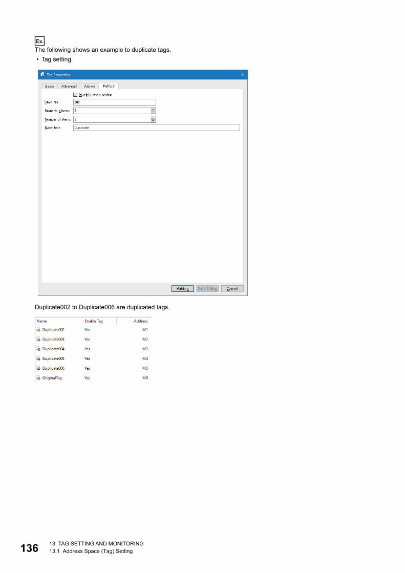
13613 TAG SETTING AND MONITORING13.1 Address Space (Tag) Setting
Ex.
The following shows an example to duplicate tags.
• Tag setting
Duplicate002 to Duplicate006 are duplicated tags.

13 TAG SETTING AND MONITORING13.1 Address Space (Tag) Setting 137
13
Details of address specificationER: Memory block: address - When a memory block is an address 1 to 256, specify an address of ER linear in decimal in
Configuration Tool.
When a memory block is an address 1 to 256, specify an address of ER linear in decimal in Configuration Tool.
Specify an address for a ZR register in decimal.
Address rangeAvailable address ranges depend on used MX devices.
For details on addresses, refer to the user's manual of each MX device.
The address range of devices supported by Configuration Tool can be checked in the "Supported Devices" screen. (Page
131 PLC device list screen)
Start address specificationSpecify the start address of a selected data block.
Available data block registerB, CC, CN, CS, D, ER, F, FT, GV:, L, LCC, LCN, LCS, LTC, LTN, LTS, LSTC, LSTN, LSTS, M, R, SA\B, SA\CC, SA\CN,
SA\CS, SA\D, SA\M, SA\SD, SA\SM, SA\STC, SA\STN, SA\STS, SA\TC, SA\TN, SA\TS, SA\W, SA\X, SA\Y, SB, SD, SM,
SW, STC, STN, STS, TC, TN, TS, U3En\G, W, WR, WW, X, Y, Z, ZR, #
End address specificationSpecify the end address of a selected data block.
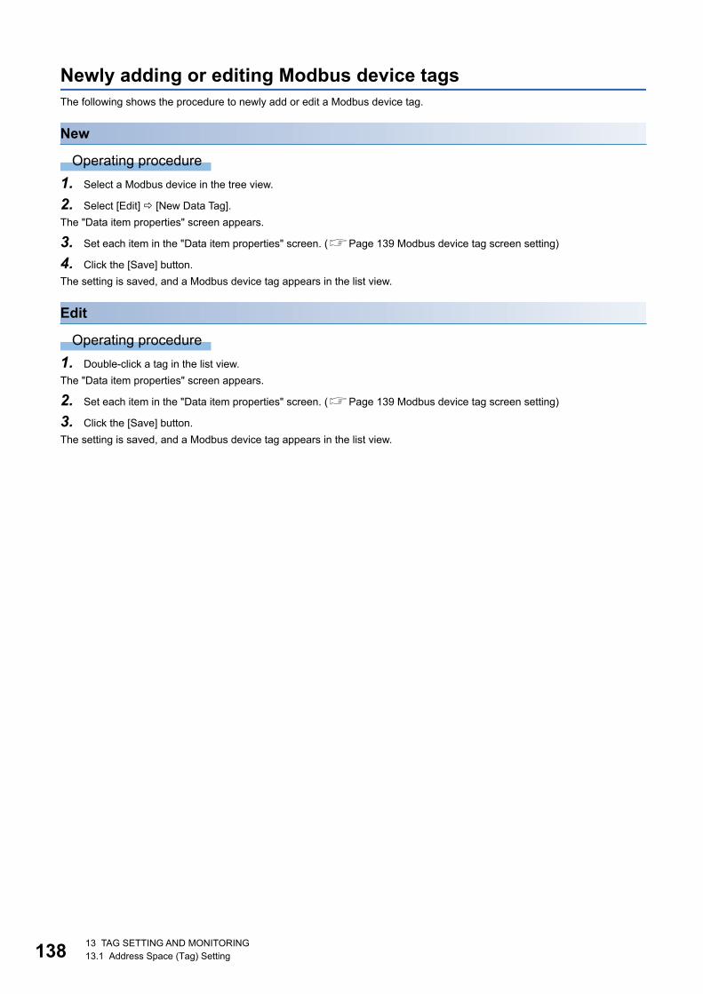
13813 TAG SETTING AND MONITORING13.1 Address Space (Tag) Setting
Newly adding or editing Modbus device tagsThe following shows the procedure to newly add or edit a Modbus device tag.
New
Operating procedure
1. Select a Modbus device in the tree view.
2. Select [Edit] [New Data Tag].
The "Data item properties" screen appears.
3. Set each item in the "Data item properties" screen. (Page 139 Modbus device tag screen setting)
4. Click the [Save] button.
The setting is saved, and a Modbus device tag appears in the list view.
Edit
Operating procedure
1. Double-click a tag in the list view.
The "Data item properties" screen appears.
2. Set each item in the "Data item properties" screen. (Page 139 Modbus device tag screen setting)
3. Click the [Save] button.
The setting is saved, and a Modbus device tag appears in the list view.
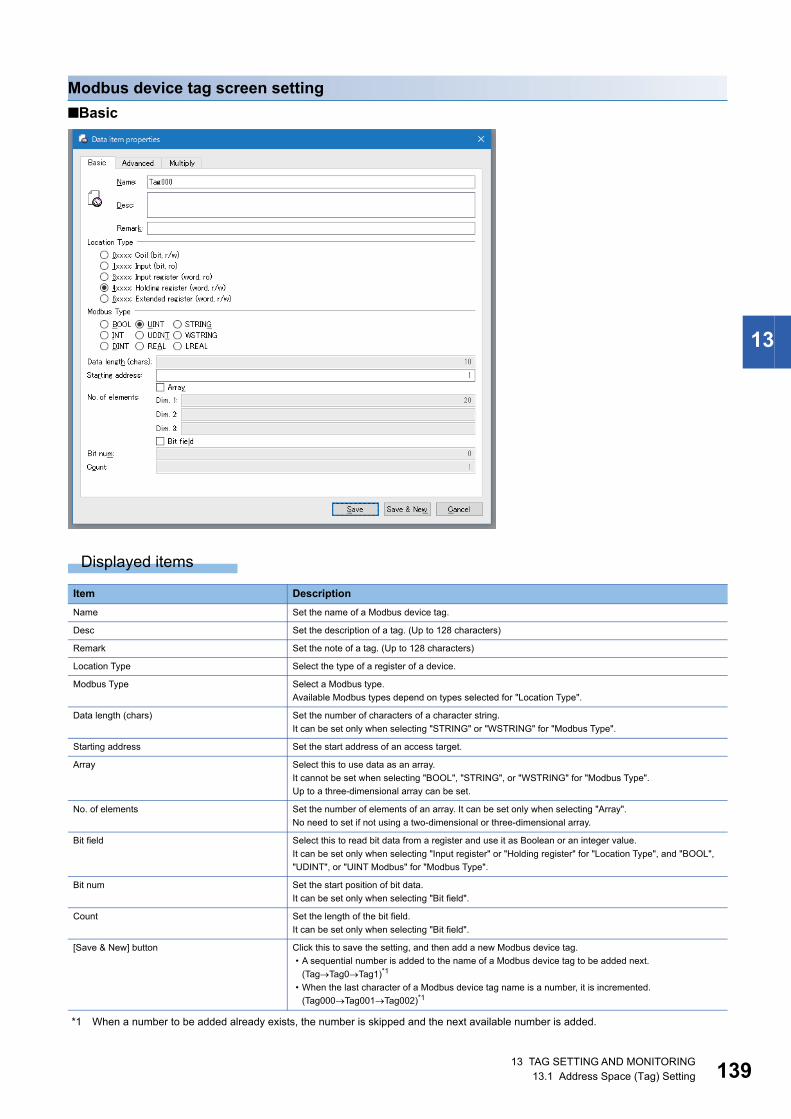
13 TAG SETTING AND MONITORING13.1 Address Space (Tag) Setting 139
13
Modbus device tag screen setting
■Basic
Displayed items
*1 When a number to be added already exists, the number is skipped and the next available number is added.
Item Description
Name Set the name of a Modbus device tag.
Desc Set the description of a tag. (Up to 128 characters)
Remark Set the note of a tag. (Up to 128 characters)
Location Type Select the type of a register of a device.
Modbus Type Select a Modbus type.
Available Modbus types depend on types selected for "Location Type".
Data length (chars) Set the number of characters of a character string.
It can be set only when selecting "STRING" or "WSTRING" for "Modbus Type".
Starting address Set the start address of an access target.
Array Select this to use data as an array.
It cannot be set when selecting "BOOL", "STRING", or "WSTRING" for "Modbus Type".
Up to a three-dimensional array can be set.
No. of elements Set the number of elements of an array. It can be set only when selecting "Array".
No need to set if not using a two-dimensional or three-dimensional array.
Bit field Select this to read bit data from a register and use it as Boolean or an integer value.
It can be set only when selecting "Input register" or "Holding register" for "Location Type", and "BOOL",
"UDINT", or "UINT Modbus" for "Modbus Type".
Bit num Set the start position of bit data.
It can be set only when selecting "Bit field".
Count Set the length of the bit field.
It can be set only when selecting "Bit field".
[Save & New] button Click this to save the setting, and then add a new Modbus device tag.
• A sequential number is added to the name of a Modbus device tag to be added next.
(TagTag0Tag1)*1
• When the last character of a Modbus device tag name is a number, it is incremented.
(Tag000Tag001Tag002)*1

14013 TAG SETTING AND MONITORING13.1 Address Space (Tag) Setting
■Advanced
Displayed items
Item Description
General Setup Enable Tag Select this to enable a tag.
Data Conversion Swap word/byte order Select this to swap the order of bytes in data.
WORD type: 1234h 3412h
DWORD type: 12345678h 78563412h
Convert to word Select this to convert a tag value to a word or a double word when requesting to read or write
from an OPC UA client application.
■INT type tag
• Reading: Data is converted to a double word and read. (A sign is considered.)
• Writing: Data is converted to a word and written to a tag.
■DINT type tag
• Reading: Data is converted to a word and read.
• Writing: Data is converted to a double word and written to a tag. (A sign is considered.)
Use conversion Select this to use a conversion definition.
Conversion Select a conversion definition.
[New Conversion] button Click this to create a new conversion definition. (Page 164 Setting Conversion Definitions)
Simulation Simulate Select this to simulate a device.
Simulation Signal Select a simulation signal definition.
[New Simulation signal] button Click this to create a new simulation signal definition. (Page 171 Setting Simulation Signal
Definitions)
Use Manual Value Select this to use a manual value.
When enabled, a constant is fixed to a tag value during simulation.
Manual Value Set a value to fix to a tag during simulation.

13 TAG SETTING AND MONITORING13.1 Address Space (Tag) Setting 141
13
■Multiply
Displayed items
*1 When a number to be added already exists, the number is skipped and the next available number is added.
Alarms Generate Alarms Select this to use a limit alarm definition or a digital alarm definition.
It cannot be set when selecting "STRING" or "WSTRING" for "Modbus Type" in the [Basic] tab.
Message prefix Set a message prefix to add to an alarm.
A set word is displayed at the start of an alarm message.
Limit Alarm Select a limit alarm definition.
It cannot be set when selecting "BOOL" for "Modbus Type" in the [Basic] tab.
[New Limit Alarm Definition] button Click this to create new limit alarm definitions. (Page 158 Newly adding or editing limit alarm
definitions)
Digital Alarm Select a digital alarm definition.
It can be set only when selecting "BOOL" for "Modbus Type" in the [Basic] tab.
[New Digital Alarm Definition]
button
Click this to create new digital alarm definitions. (Page 161 Newly adding or editing digital
alarm definitions)
Item Description
Multiply when saving Select this to duplicate tags when saving a Modbus device tag.
Start No. Set the start number of a number added to a tag name when duplicating Modbus device tags.
Numeric places Set the number of digits in the numeric part of a tag name.
Number of items Set the number of tags to duplicate.
Base text Set the name of a tag.
[Save]/[Multiply] button When selecting "Multiply when saving", the [Save] button is changed to the [Multiply] button.
Click the [Save] button to save the setting.
Click the [Multiply] button to duplicate tags with set contents.
[Save & New] button Click this to save the setting, and then add a new Modbus device tag.
• A sequential number is added to the name of a Modbus device tag to be added next.
(TagTag1Tag2)*1
• When the last character of a Modbus device tag name is a number, it is incremented.
(Tag000Tag001Tag002)*1
Item Description

14213 TAG SETTING AND MONITORING13.1 Address Space (Tag) Setting
Deleting tagsThe following shows the procedure to delete a tag.
Operating procedure
1. Select a tag to delete in the list view. (Multiple selections allowed.)
2. Select [Edit] [Delete].
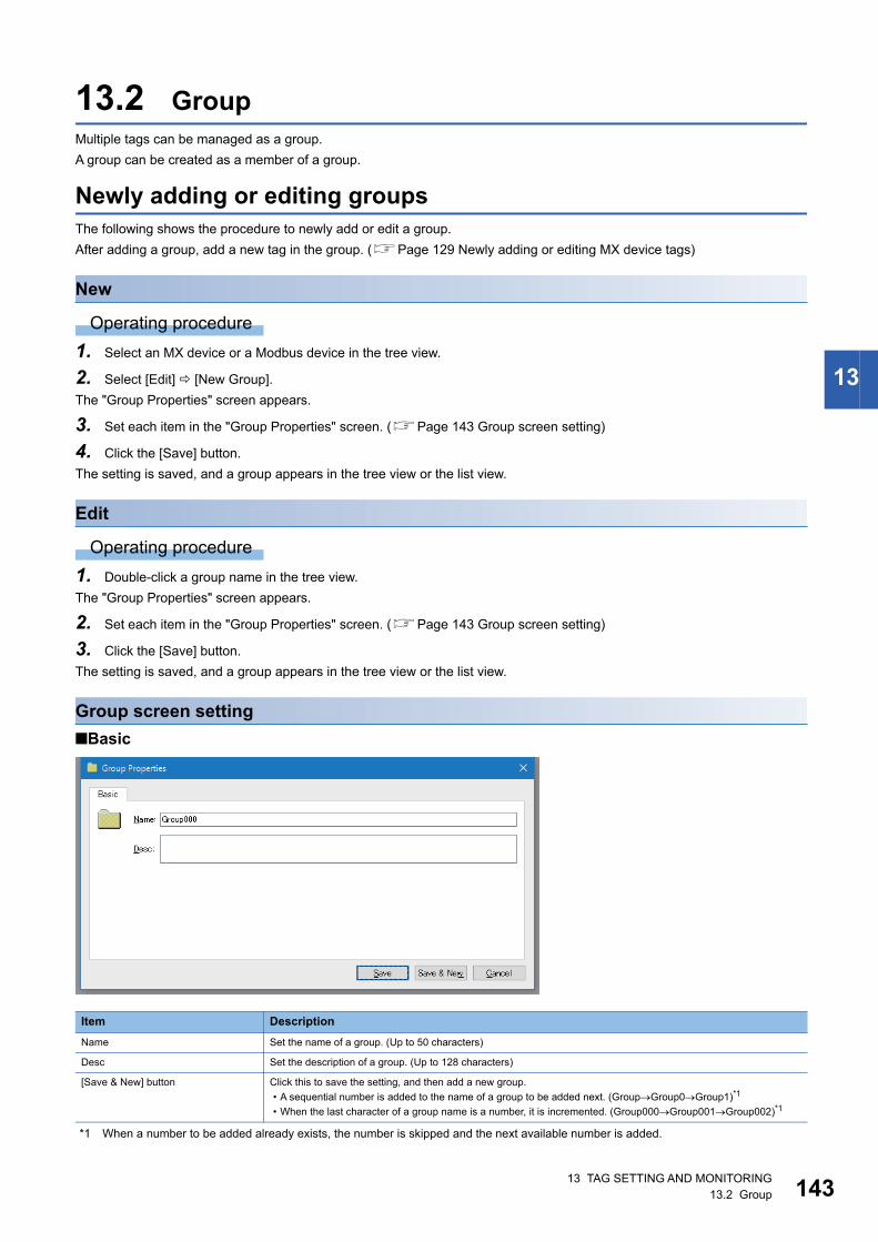
13 TAG SETTING AND MONITORING13.2 Group 143
13
13.2 GroupMultiple tags can be managed as a group.
A group can be created as a member of a group.
Newly adding or editing groupsThe following shows the procedure to newly add or edit a group.
After adding a group, add a new tag in the group. (Page 129 Newly adding or editing MX device tags)
New
Operating procedure
1. Select an MX device or a Modbus device in the tree view.
2. Select [Edit] [New Group].
The "Group Properties" screen appears.
3. Set each item in the "Group Properties" screen. (Page 143 Group screen setting)
4. Click the [Save] button.
The setting is saved, and a group appears in the tree view or the list view.
Edit
Operating procedure
1. Double-click a group name in the tree view.
The "Group Properties" screen appears.
2. Set each item in the "Group Properties" screen. (Page 143 Group screen setting)
3. Click the [Save] button.
The setting is saved, and a group appears in the tree view or the list view.
Group screen setting
■Basic
*1 When a number to be added already exists, the number is skipped and the next available number is added.
Item Description
Name Set the name of a group. (Up to 50 characters)
Desc Set the description of a group. (Up to 128 characters)
[Save & New] button Click this to save the setting, and then add a new group.
• A sequential number is added to the name of a group to be added next. (GroupGroup0Group1)*1
• When the last character of a group name is a number, it is incremented. (Group000Group001Group002)*1

14413 TAG SETTING AND MONITORING13.2 Group
Deleting groupsThe following shows the procedure to delete a group.
Operating procedure
1. Select a group to delete in the tree view (multiple selections not allowed) or in the list view (multiple selections allowed).
2. Select [Edit] [Delete].
13 TAG SETTING AND MONITORING13.3 Structure Labels 145
13
13.3 Structure LabelsThis section shows structure labels created by using a structure definition including basic data types (such as word or bit).
For details on the structure definition, refer to the following section.
Page 168 Setting Structure Definitions
Newly adding or editing structure labelsThe following shows the procedure to newly add or edit a structure label.
New
Operating procedure
1. Set a structure definition. (Page 168 Setting Structure Definitions)
2. Select an MX device in the tree view.
3. Select [Edit] [New Structure].
The "Add structure label" screen appears.
4. Set each item in the "Add structure label" screen. (Page 146 Structure label definition screen setting)
5. Click the [Finish] button.
The setting is saved, and a structure label appears in the tree view and the list view.
Edit
Operating procedure
1. Double-click a structure label in the tree view.
The "Structure Type Properties" screen appears.
2. Set each item in the "Structure Type Properties" screen. (Page 146 Structure label definition screen setting)
3. Click the [Finish] button.
The setting is saved, and a structure label appears in the tree view and the list view.

14613 TAG SETTING AND MONITORING13.3 Structure Labels
Structure label definition screen setting
LabelEnter the basic details of a label, and select a data type.
Window
Displayed items
Item Description
Basic details Global label name Set the name of a structure label.
Comment Set a comment.
Remark Set a remark if necessary.
Array Element ARRAY Select this to use a structure as an array.
Up to a three-dimensional array can be set.
Lower bound Set the first element number of each dimension of an array.
Elements Set the number of elements of each dimension of an array.
Do not enter any value for an unused dimension.
SDT - Structured Data Type Select a structure definition used for a new structure label. (Page 168 Setting Structure Definitions)

13 TAG SETTING AND MONITORING13.3 Structure Labels 147
13
AddressSet an address of a structure label.
Page 147 Non-array structure label
Page 148 Structure array label
■Non-array structure label
Window
Displayed items
Precautions
Not all connected devices support bit specification of a word device.
If specifying a bit to a connected device that does not support it, a warning appears.
In this case, unselect "Use Bit Designation".
Item Description
(1) Address area The address of each element of a structure is displayed.
Double-click a cell in the "Device" column to enter or edit the address.
For a structure array, only the start address is displayed.
The following addresses are assigned automatically by selecting "Automatic filling".
(2) Automatic filling Select this to assign available addresses automatically.
(3) Use Bit Designation Select this to specify a bit of a word device.
In the above example of a structure, the address 'D102.0' can be assigned to BOOL variable VAR02.
Unselect this not to specify a bit of a word device.
In this case, enter an address manually.
(1)
(2) (3)

14813 TAG SETTING AND MONITORING13.3 Structure Labels
■Structure array labelOnly the start address is displayed.
The following addresses are assigned automatically by selecting "Automatic filling".
Window
Displayed items
Precautions
• Not all connected devices support bit specification of a word device. If specifying a bit to a connected device that does not
support it, a warning appears. In this case, unselect "Use Bit Designation".
Item Description
(1) Element selection Elements of a structure array are displayed in a tree.
(2) Address area Set an address to assign.
An address can only be set to the first element of an array.
An address for an offset value from an address set to the first is automatically assigned to an address following the start address.
(3) Structure Array Offset
Value
Set an offset value of a structure array.
• Word device: Set an offset value of an address that is automatically set in an element of an array. (When VAR00 is in the first
array index D100 and an offset of a word device is set to 10, the next index VAR00 starts from D110.)
• Bit device: Set a difference of an address between array elements as an offset value for the start address. An address
automatically entered can be set at a constant interval between array elements of a structure array by setting an offset value.
(4) Use Bit Designation Select this to specify a bit of a word device.
Unselect this not to specify a bit of a word device.
In this case, enter an address manually.
(3)
(4)
(1)
(2)

13 TAG SETTING AND MONITORING13.3 Structure Labels 149
13
TagSet details for a member of a structure.
Item Description
(1) Element selection Members of a structure are displayed in a tree.
The setting contents of an element selected in the tree are displayed on the right side of the screen.
(2) Detailed setting Items that can be set to a selected element are displayed.
It consists of three tabs: [General], [Advanced], and [Alarms].
(1) (2)
15013 TAG SETTING AND MONITORING13.3 Structure Labels
■General setting
Window
Displayed items
*1 Appears only for MX devices.
Item Description
General Setup Enable Tag Select this to enable a structure tag. (Applies to all elements of the structure.)
Data Polling*1 Poll. Method Set a polling cycle. A setting is shared between all elements of a structure.
Access Rights Select an access right.
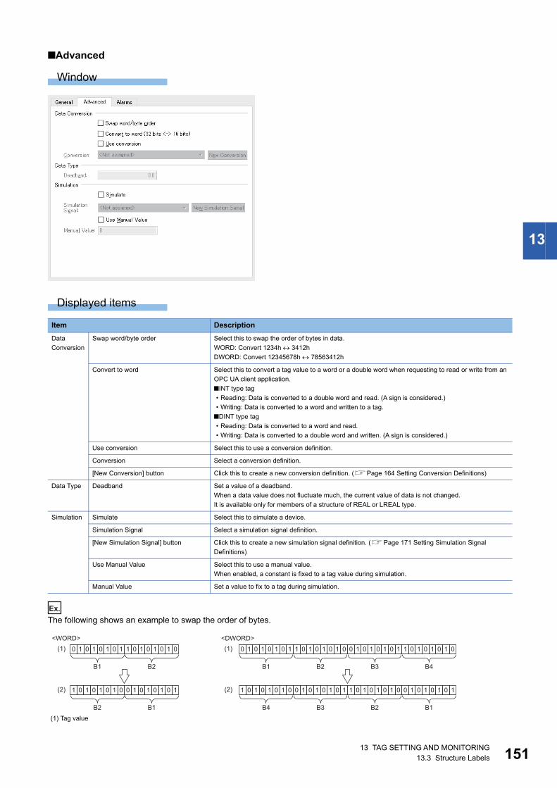
13 TAG SETTING AND MONITORING13.3 Structure Labels 151
13
■Advanced
Window
Displayed items
Ex.
The following shows an example to swap the order of bytes.
Item Description
Data
Conversion
Swap word/byte order Select this to swap the order of bytes in data.
WORD: Convert 1234h 3412h
DWORD: Convert 12345678h 78563412h
Convert to word Select this to convert a tag value to a word or a double word when requesting to read or write from an
OPC UA client application.
■INT type tag
• Reading: Data is converted to a double word and read. (A sign is considered.)
• Writing: Data is converted to a word and written to a tag.
■DINT type tag
• Reading: Data is converted to a word and read.
• Writing: Data is converted to a double word and written. (A sign is considered.)
Use conversion Select this to use a conversion definition.
Conversion Select a conversion definition.
[New Conversion] button Click this to create a new conversion definition. (Page 164 Setting Conversion Definitions)
Data Type Deadband Set a value of a deadband.
When a data value does not fluctuate much, the current value of data is not changed.
It is available only for members of a structure of REAL or LREAL type.
Simulation Simulate Select this to simulate a device.
Simulation Signal Select a simulation signal definition.
[New Simulation Signal] button Click this to create a new simulation signal definition. (Page 171 Setting Simulation Signal
Definitions)
Use Manual Value Select this to use a manual value.
When enabled, a constant is fixed to a tag value during simulation.
Manual Value Set a value to fix to a tag during simulation.
(1) Tag value
<WORD> <DWORD>
B1 B2
0 1 0 1 0 1 0 1 1 0 1 0 1 0 01
B1
0 1 0 1 0 1 0 1
B1 B2
0 1 0 1 0 1 0 1 1 0 1 0 1 0 01
B3 B4
0 1 0 1 0 1 0 1 1 0 1 0 1 0 01
B2
1 0 1 0 1 0 01
B3
0 1 0 1 0 1 0 1
B4
1 0 1 0 1 0 01
B1
0 1 0 1 0 1 0 1
B2
1 0 1 0 1 0 01
(1)
(2)
(1)
(2)

15213 TAG SETTING AND MONITORING13.3 Structure Labels
Ex.
The following shows an example to swap a value of an INT type tag to a word.
Reading
Writing
(2) Value in an OPC UA client application
(1) Tag value
(2) Value in an OPC UA client application
(3) A sign is considered.
(1) Tag value
(2) Value in an OPC UA client application
(3) A sign is not considered.
1 0 0 0 0 0 0 0 0 0 0 0 0 0 10
1 1 1 1 1 1 1 11 1 1 1 1 1 11 0 0 0 0 0 0 0 11 0 0 0 0 0 00
(1)
(2)
(3)
0 1 0 1 0 1 0 1 1 0 1 0 1 0 01
1 0 1 0 1 0 1 01 1 0 1 0 1 10 1 0 1 0 1 0 1 00 1 0 1 0 1 10
(3)
(1)
(2)
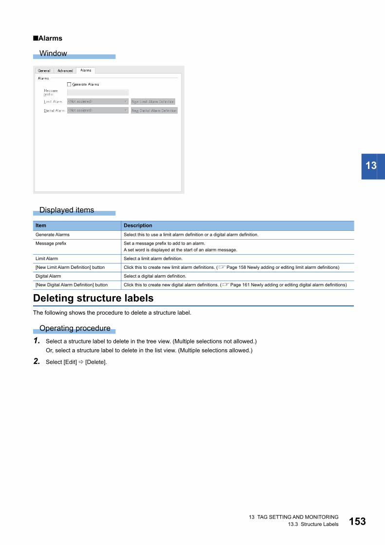
13 TAG SETTING AND MONITORING13.3 Structure Labels 153
13
■Alarms
Window
Displayed items
Deleting structure labelsThe following shows the procedure to delete a structure label.
Operating procedure
1. Select a structure label to delete in the tree view. (Multiple selections not allowed.)
Or, select a structure label to delete in the list view. (Multiple selections allowed.)
2. Select [Edit] [Delete].
Item Description
Generate Alarms Select this to use a limit alarm definition or a digital alarm definition.
Message prefix Set a message prefix to add to an alarm.
A set word is displayed at the start of an alarm message.
Limit Alarm Select a limit alarm definition.
[New Limit Alarm Definition] button Click this to create new limit alarm definitions. (Page 158 Newly adding or editing limit alarm definitions)
Digital Alarm Select a digital alarm definition.
[New Digital Alarm Definition] button Click this to create new digital alarm definitions. (Page 161 Newly adding or editing digital alarm definitions)

15413 TAG SETTING AND MONITORING13.4 Monitoring
13.4 MonitoringThis section explains the method for monitoring a set tag.
Set the following before monitoring.
Page 32 Communication with Devices and Tags
Page 34 Starting or Stopping Polling
Operating procedure
Select [View] [Monitor view], or click the icon ( ) on the toolbar.
Monitoring a tag starts in the list view.
Precautions
A value that fails to be read is displayed in red.

13 TAG SETTING AND MONITORING13.5 Writing Values to Tags 155
13
13.5 Writing Values to TagsWhen a tag is being monitored in the list view, a value can be written to each displayed tag.
A written value is applied to an address of a connection destination.
Data type Entering method
Bool/Bit "True" or "False" is displayed.
Double-click a value to display the checkbox and edit a value.
Character string A value is displayed with enclosed in quotes (for example, "STRINGVALUE").
To change a value, enter it without quotes.
Array (one-dimension) A value is displayed with enclosed in curly brackets (for example, {1, 2, 3}).
A value can be edited by double-clicking it.
Array (two or more
dimension)
"Double click to display value" is displayed for a two or more dimensional array.
A value can be edited by double-clicking it.
To change a dimension of an array, click the [Set Dimensions] button.
Enter a dimension of an array by using a comma as a delimiter in the displayed "Set Matrix Dimensions" screen.

15614 STATISTICS INFORMATION DISPLAY14.1 Display Method
14 STATISTICS INFORMATION DISPLAY
This chapter explains the display of statistics information of data in MX OPC UA Server.
14.1 Display Method
Operating procedure
1. Select a device to display the statistics information in the tree view.
2. Select [View] [Statistics], or click the icon ( ) on the toolbar.
Window
■TransactionStatistics information on transactions of the device is displayed.
Displayed items
Item Description
Transmits The number of messages that Server sent to a device is displayed.
Receives The number of messages that Server received from the device is displayed.
The number of invalid messages is included.
Timeouts The number of times there was no response from the device within a set time is displayed.
Retries The number of retries for establishing a communication line is displayed.
Errors The total number of protocol errors received in the device is displayed. A protocol error occurs when:
• A message with a sum check error caused by interference of the device or a connection failure is received.
• Data is acquired for a register that does not exist in the device.
For details on the cause of the error, check the latest error for all data blocks configured for the driver.
Overruns The total number of timed-out sessions for polling processing in Server is displayed. It counted when a response time
from a communication device is increased due to a large volume of traffic and a tag cannot be polled within a set
polling interval.
Last Transmit Time The last time that Server sent data to the device is displayed.
Last Receive Time The last time that Server successfully received data from the device is displayed.
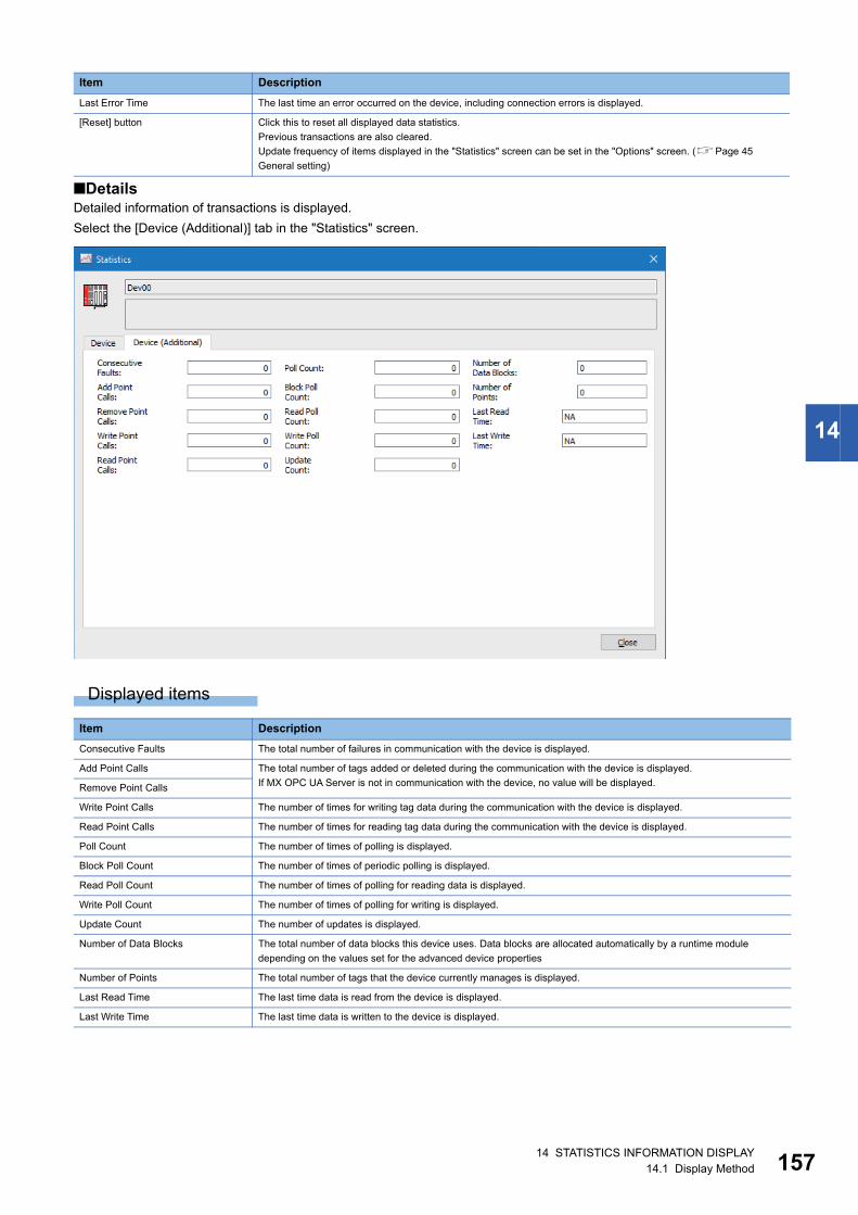
14 STATISTICS INFORMATION DISPLAY14.1 Display Method 157
14
■DetailsDetailed information of transactions is displayed.
Select the [Device (Additional)] tab in the "Statistics" screen.
Displayed items
Last Error Time The last time an error occurred on the device, including connection errors is displayed.
[Reset] button Click this to reset all displayed data statistics.
Previous transactions are also cleared.
Update frequency of items displayed in the "Statistics" screen can be set in the "Options" screen. (Page 45
General setting)
Item Description
Consecutive Faults The total number of failures in communication with the device is displayed.
Add Point Calls The total number of tags added or deleted during the communication with the device is displayed.
If MX OPC UA Server is not in communication with the device, no value will be displayed.Remove Point Calls
Write Point Calls The number of times for writing tag data during the communication with the device is displayed.
Read Point Calls The number of times for reading tag data during the communication with the device is displayed.
Poll Count The number of times of polling is displayed.
Block Poll Count The number of times of periodic polling is displayed.
Read Poll Count The number of times of polling for reading data is displayed.
Write Poll Count The number of times of polling for writing is displayed.
Update Count The number of updates is displayed.
Number of Data Blocks The total number of data blocks this device uses. Data blocks are allocated automatically by a runtime module
depending on the values set for the advanced device properties
Number of Points The total number of tags that the device currently manages is displayed.
Last Read Time The last time data is read from the device is displayed.
Last Write Time The last time data is written to the device is displayed.
Item Description

15815 VARIOUS DEFINITIONS (ALARM, CONVERSION, POLLING, STRUCTURE)15.1 Setting Alarm Definitions
15 VARIOUS DEFINITIONS (ALARM, CONVERSION, POLLING, STRUCTURE)
Alarm definitions, conversion definitions, polling definitions, and structure definitions can be set in advance.
15.1 Setting Alarm DefinitionsThe following alarm definitions can be set.
• Limit alarm (high high limit, high limit, low limit, low low limit)
• Digital alarm
Newly adding or editing limit alarm definitionsA limit alarm outputs a warning message when a tag value exceeded the set limit value.
Four levels can be set for a limit alarm: high high limit, high limit, low limit, low low limit.
The following shows the procedure to newly add or edit a limit alarm definition.
Operating procedure
■New
1. Select "Alarm Definitions" in the tree view.
2. Select [Edit] [New Limit Alarm Definition].
The "Limit Alarm Properties" screen appears.
3. Set each item in the "Limit Alarm Properties" screen.(Page 159 Limit alarm definition screen setting)
4. Click the [Save] button.
The setting is saved, and a limit alarm definition appears in the list view.
■Edit
1. Double-click a limit alarm definition in the list view.
The "Limit Alarm Properties" screen appears.
2. Set each item in the "Limit Alarm Properties" screen.(Page 159 Limit alarm definition screen setting)
3. Click the [Save] button.
The setting is saved, and a limit alarm definition appears in the list view.
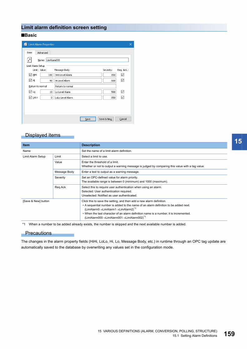
15 VARIOUS DEFINITIONS (ALARM, CONVERSION, POLLING, STRUCTURE)15.1 Setting Alarm Definitions 159
15
Limit alarm definition screen setting
■Basic
Displayed items
*1 When a number to be added already exists, the number is skipped and the next available number is added.
Precautions
The changes in the alarm property fields (HiHi, LoLo, Hi, Lo, Message Body, etc.) in runtime through an OPC tag update are
automatically saved to the database by overwriting any values set in the configuration mode.
Item Description
Name Set the name of a limit alarm definition.
Limit Alarm Setup Limit Select a limit to use.
Value Enter the threshold of a limit.
Whether or not to output a warning message is judged by comparing this value with a tag value.
Message Body Enter a text to output as a warning message.
Severity Set an OPC-defined value for alarm priority.
The available range is between 0 (minimum) and 1000 (maximum).
Req.Ack Select this to require user authentication when using an alarm.
Selected: User authentication required.
Unselected: Notified as user authenticated.
[Save & New] button Click this to save the setting, and then add a new alarm definition.
• A sequential number is added to the name of an alarm definition to be added next.
(LimAlarm0LimAlarm1LimAlarm2)*1
• When the last character of an alarm definition name is a number, it is incremented.
(LimAlarm000LimAlarm001LimAlarm002)*1

16015 VARIOUS DEFINITIONS (ALARM, CONVERSION, POLLING, STRUCTURE)15.1 Setting Alarm Definitions
■Advanced
Displayed items
Precautions
If a deadband value is larger than the difference between two limits set in the [Basic] tab, an alarm limit may not work properly.
(Example: low low limit is '9', low limit is '10', deadband is '2')
Item Description
OPC Data Setup Deadband Set the variation width of a data value.
When a deadband value is set, a warning message is not output when data fluctuates within the range of the
value.
Therefore, when reading or writing data that fluctuates, more warning messages than necessary are not
output.

15 VARIOUS DEFINITIONS (ALARM, CONVERSION, POLLING, STRUCTURE)15.1 Setting Alarm Definitions 161
15
Newly adding or editing digital alarm definitionsA digital alarm outputs warning message when a tag value is different from the set value (True or False).
The following shows the procedure to newly add or edit a digital alarm definition.
Operating procedure
■New
1. Select "Alarm Definitions" in the tree view.
2. Select [Edit] [New Digital Alarm Definition].
The "Digital Alarm Properties" screen appears.
3. Set each item in the "Digital Alarm Properties" screen. (Page 162 Digital alarm definition screen setting)
4. Click the [Save] button.
The setting is saved, and a digital alarm definition appears in the list view.
■Edit
1. Double-click a digital alarm definition in the list view.
The "Digital Alarm Properties" screen appears.
2. Set each item in the "Digital Alarm Properties" screen. (Page 162 Digital alarm definition screen setting)
3. Click the [Save] button.
The setting is saved, and a digital alarm definition appears in the list view.

16215 VARIOUS DEFINITIONS (ALARM, CONVERSION, POLLING, STRUCTURE)15.1 Setting Alarm Definitions
Digital alarm definition screen setting
■Basic
Displayed items
*1 When a number to be added already exists, the number is skipped and the next available number is added.
Item Description
Name Set the name of a digital alarm definition.
Digital Alarm Setup Limit Select this to use a digital alarm.
Value Select a digital alarm value.
Message Body Enter a text to output as a warning message.
Severity Set an OPC-defined value for alarm priority.
The available range is between 0 (minimum) and 1000 (maximum).
Req.Ack Select this to require user authentication when using an alarm.
Selected: User authentication required.
Unselected: Notified as user authenticated.
Return to normal Enter a text to display as a message when an alarm is processed (when a value became normal).
[Save & New] button Click this to save the setting, and then add a new alarm definition.
• A sequential number is added to the name of an alarm definition to be added next.
(DigAlarm0DigAlarm1DigAlarm2)*1
• When the last character of an alarm definition name is a number, it is incremented.
(DigAlarm000DigAlarm001DigAlarm002)*1

15 VARIOUS DEFINITIONS (ALARM, CONVERSION, POLLING, STRUCTURE)15.1 Setting Alarm Definitions 163
15
Associating alarm definitions with tagsThe following shows the procedure to associate a created alarm definition with a tag.
1. Double-click a tag in the list view of an MX device or a Modbus device.
2. Display the [Alarms] tab in the "Tag Properties" screen or the [Advanced] tab in the "Data item properties" screen.
(Page 129 Address Space (Tag) Setting)
3. Select "Generate Alarms".
4. Select an alarm definition from the pull-down list of "Limit Alarm" or "Digital Alarm".
Deleting alarm definitionsThe following shows the procedure to delete an alarm definition.
Alarm definitions used for tags cannot be deleted.
Operating procedure
1. Select an alarm definition to delete in the list view.
2. Select [Edit] [Delete].
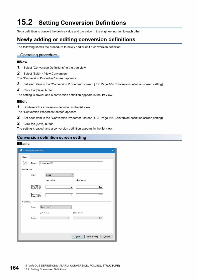
16415 VARIOUS DEFINITIONS (ALARM, CONVERSION, POLLING, STRUCTURE)15.2 Setting Conversion Definitions
15.2 Setting Conversion DefinitionsSet a definition to convert the device value and the value in the engineering unit to each other.
Newly adding or editing conversion definitionsThe following shows the procedure to newly add or edit a conversion definition.
Operating procedure
■New
1. Select "Conversion Definitions" in the tree view.
2. Select [Edit] [New Conversion].
The "Conversion Properties" screen appears.
3. Set each item in the "Conversion Properties" screen. (Page 164 Conversion definition screen setting)
4. Click the [Save] button.
The setting is saved, and a conversion definition appears in the list view.
■Edit
1. Double-click a conversion definition in the list view.
The "Conversion Properties" screen appears.
2. Set each item in the "Conversion Properties" screen. (Page 164 Conversion definition screen setting)
3. Click the [Save] button.
The setting is saved, and a conversion definition appears in the list view.
Conversion definition screen setting
■Basic

15 VARIOUS DEFINITIONS (ALARM, CONVERSION, POLLING, STRUCTURE)15.2 Setting Conversion Definitions 165
15
Displayed items
*1 Alphanumeric characters, underscores (_), and hyphens (-) can be used.*2 When a number to be added already exists, the number is skipped and the next available number is added.
Ex.
The following shows an example for each clamp type when converting the device value '3000' with the settings below.
Conversion type: Linear
Range of the engineering unit (EU): 0 to 400
Range of the instrument range (IR): 0 to 2000
Associating conversion definitions with tagsThe following shows the procedure to associate a created conversion definition with a tag.
1. Double-click a tag in the list view of an MX device or a Modbus device.
2. Display the [Advanced] tab in the "Tag Properties" screen or the "Data item properties" screen. (Page 129 Address
Space (Tag) Setting)
3. Select "Use conversion" under "Data Conversion".
4. Select a created conversion definition from the pull-down list of "Conversion".
Deleting conversion definitionsThe following shows the procedure to delete a conversion definition.
Conversion definitions associated with tags cannot be deleted.
Operating procedure
1. Select a conversion definition to delete in the list view.
2. Select [Edit] [Delete].
Item Description
Name Set the name of a conversion definition. (Up to 50 characters)*1
Conversion Type Select a conversion type.
Engineering Units (EU) Set the minimum value and the maximum value in engineering units.
Instrument Range (IR) Set a device value equivalent to a value in engineering units.
Clamping Type Select processing when a value exceeds the range.
Range Set the maximum value and the minimum value of clamping (range of double type).
[Save & New] button Click this to save the setting, and then add a new conversion definition.
• A sequential number is added to the name of a conversion definition to be added next.
(ConversionConversion1Conversion2)*2
• When the last character of a conversion definition name is a number, it is incremented.
(Conversion000Conversion001Conversion002)*2
Type Range Value after conversion
None 600
Clamp on EU 0 to 400 (range of engineering units (EU)) 400
As specified 0 to 200 200
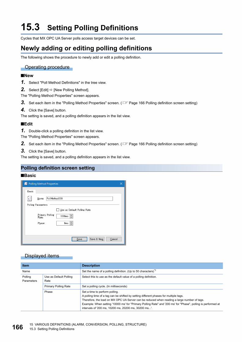
16615 VARIOUS DEFINITIONS (ALARM, CONVERSION, POLLING, STRUCTURE)15.3 Setting Polling Definitions
15.3 Setting Polling DefinitionsCycles that MX OPC UA Server polls access target devices can be set.
Newly adding or editing polling definitionsThe following shows the procedure to newly add or edit a polling definition.
Operating procedure
■New
1. Select "Poll Method Definitions" in the tree view.
2. Select [Edit] [New Polling Method].
The "Polling Method Properties" screen appears.
3. Set each item in the "Polling Method Properties" screen. (Page 166 Polling definition screen setting)
4. Click the [Save] button.
The setting is saved, and a polling definition appears in the list view.
■Edit
1. Double-click a polling definition in the list view.
The "Polling Method Properties" screen appears.
2. Set each item in the "Polling Method Properties" screen. (Page 166 Polling definition screen setting)
3. Click the [Save] button.
The setting is saved, and a polling definition appears in the list view.
Polling definition screen setting
■Basic
Displayed items
Item Description
Name Set the name of a polling definition. (Up to 50 characters)*1
Polling
Parameters
Use as Default Polling
Rate
Select this to use as the default value of a polling definition.
Primary Polling Rate Set a polling cycle. (In milliseconds)
Phase Set a time to perform polling.
A polling time of a tag can be shifted by setting different phases for multiple tags.
Therefore, the load on MX OPC UA Server can be reduced when reading a large number of tags.
Example: When setting '10000 ms' for "Primary Polling Rate" and '200 ms' for "Phase", polling is performed at
intervals of '200 ms, 10200 ms, 20200 ms, 30200 ms...'.
15 VARIOUS DEFINITIONS (ALARM, CONVERSION, POLLING, STRUCTURE)15.3 Setting Polling Definitions 167
15
*1 Alphanumeric characters, underscores (_), and hyphens (-) can be used.*2 When a number to be added already exists, the number is skipped and the next available number is added.
Associating polling definitions with tagsThe following shows the procedure to associate a created polling definition with a tag.
Operating procedure
1. Double-click a tag in the list view of an MX device.
2. Display the [Basic] tab in the "Tag Properties" screen. (Page 129 Address Space (Tag) Setting)
3. Select a created polling definition from the pull-down list of "Poll. Method" in "Data Polling".
Deleting polling definitionsThe following shows the procedure to delete a polling definition.
Polling definitions associated with tags cannot be deleted.
Operating procedure
1. Select a polling definition to delete in the list view.
2. Select [Edit] [Delete].
[Save & New] button Click this to save the setting, and then add a new polling definition.
• A sequential number is added to the name of a polling definition to be added next.
(PollMethodPollMethod1PollMethod2)*2
• When the last character of a polling definition name is a number, it is incremented.
(PollMethod000PollMethod001PollMethod002)*2
Item Description

16815 VARIOUS DEFINITIONS (ALARM, CONVERSION, POLLING, STRUCTURE)15.4 Setting Structure Definitions
15.4 Setting Structure DefinitionsStructure definitions used as structure labels for MX devices or Modbus devices can be set.
Newly adding or editing structure definitionsThe following shows the procedure to newly add or edit a structure definition.
Operating procedure
■New
1. Select "Structure Type Declarations" in the tree view.
2. Select [Edit] [New StructureType].
The "Structure Type Properties" screen appears.
3. Right-click a structure name in "Structure Hierarchy" in the "Structure Type Properties" screen, and select [Add variable].
4. Set each item in the "Select data type" screen. (Page 169 Structure definition screen setting)
5. Click the [Save] button.
The setting is saved, and a structure definition appears in the list view.
■Edit
1. Double-click a structure name in the tree view.
The "Structure Type Properties" screen appears.
2. Set each item in the "Structure Type Properties" screen. (Page 169 Structure definition screen setting)
3. Click the [Save] button.
The setting is saved, and a structure definition appears in the list view.
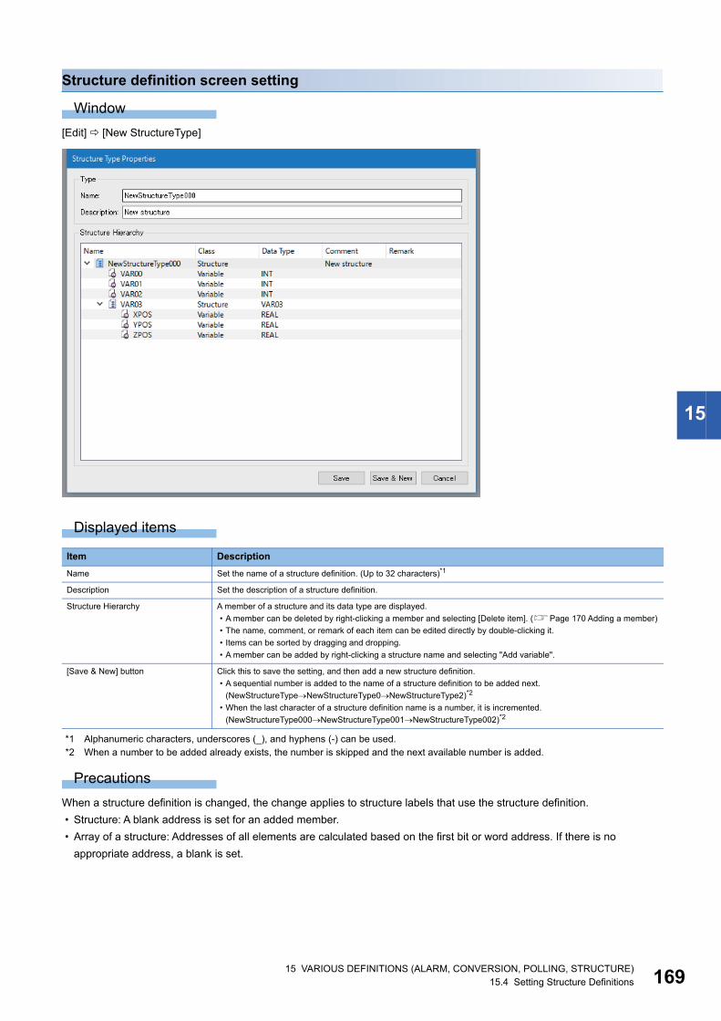
15 VARIOUS DEFINITIONS (ALARM, CONVERSION, POLLING, STRUCTURE)15.4 Setting Structure Definitions 169
15
Structure definition screen setting
Window
[Edit] [New StructureType]
Displayed items
*1 Alphanumeric characters, underscores (_), and hyphens (-) can be used.*2 When a number to be added already exists, the number is skipped and the next available number is added.
Precautions
When a structure definition is changed, the change applies to structure labels that use the structure definition.
• Structure: A blank address is set for an added member.
• Array of a structure: Addresses of all elements are calculated based on the first bit or word address. If there is no
appropriate address, a blank is set.
Item Description
Name Set the name of a structure definition. (Up to 32 characters)*1
Description Set the description of a structure definition.
Structure Hierarchy A member of a structure and its data type are displayed.
• A member can be deleted by right-clicking a member and selecting [Delete item]. (Page 170 Adding a member)
• The name, comment, or remark of each item can be edited directly by double-clicking it.
• Items can be sorted by dragging and dropping.
• A member can be added by right-clicking a structure name and selecting "Add variable".
[Save & New] button Click this to save the setting, and then add a new structure definition.
• A sequential number is added to the name of a structure definition to be added next.
(NewStructureTypeNewStructureType0NewStructureType2)*2
• When the last character of a structure definition name is a number, it is incremented.
(NewStructureType000NewStructureType001NewStructureType002)*2

17015 VARIOUS DEFINITIONS (ALARM, CONVERSION, POLLING, STRUCTURE)15.4 Setting Structure Definitions
■Adding a memberThe "Select data type" screen appears by right-clicking a structure name in "Structure Hierarchy" and selecting [Add variable].
Window
Displayed items
Deleting structure definitionsThe following shows the procedure to delete a structure definition.
Structure definitions used for structure labels cannot be deleted.
Operating procedure
1. Select a structure name to delete in the tree view.
2. Select [Edit] [Delete].
Item Description
Type class Simple types Select this to add a variable or an array.
Structure Select this to add a structure or a structure array.
Array Element ARRAY Select this to add an array.
Arrays of STRING or WSTRING cannot be set.
Up to a three-dimensional array can be set.
Lower bound Set the first element number of each dimension of an array.
Elements Set the number of elements of each dimension of an array.
Do not enter any value for an unused dimension.
Data Type Select the data type of a variable or an array.
16 SIMULATION16.1 Setting Simulation Signal Definitions 171
16
16 SIMULATION
Tags and alarms can be simulated.
16.1 Setting Simulation Signal DefinitionsSet a simulation signal definition for simulation.
Newly adding or editing simulation signal definitionsThe following shows the procedure to newly add or edit a simulation signal definition.
Operating procedure
■New
1. Select "Simulation Definitions" in the tree view.
2. Select [Edit] [New Simulation Signal].
The "Simulation Signal Properties" screen appears.
3. Set each item in the "Simulation Signal Properties" screen. (Page 172 Simulation signal definition screen setting)
4. Click the [Save] button.
The setting is saved, and a simulation signal definition appears in the list view.
■Edit
1. Double-click a simulation signal definition in the list view.
The "Simulation Signal Properties" screen appears.
2. Set each item in the "Simulation Signal Properties" screen. (Page 172 Simulation signal definition screen setting)
3. Click the [Save] button.
The setting is saved, and a simulation signal definition appears in the list view.

17216 SIMULATION16.1 Setting Simulation Signal Definitions
Simulation signal definition screen setting
■Basic
Displayed items
*1 Alphanumeric characters, underscores (_), and hyphens (-) can be used.*2 When a number to be added already exists, the number is skipped and the next available number is added.
Item Description
Name Set the name of a simulation signal definition. (Up to 50 characters)*1
Signal Type Select a signal type.
The following shows available signal types.
• Read Count: A value of each tag is incremented when reading an item.
• Write Count: A value of each tag is incremented when writing an item.
• Random: Values are randomly generated within the range of values set for "Position" and "Amplitude".
• Ramp, Sine, Square, Triangle, Step: Periodical signals. The signal time can be set for "Period" and "Phase" in "Signal
Parameters". Set the signal frequency (in milliseconds) for "Period" , while set the start position of a signal (in degrees) for
"Phase". When selecting "Square", set the ratio of the maximum value and the minimum value of a signal for "Ratio", while
selecting "Triangle", set a signal steepness for "Ratio".
Signal Parameters Set the following items:
• Position
• Amplitude
• Period (ms)
• Phase (deg)
• Ratio
• No. of steps
[Save & New] button Click this to save the setting, and then add a new simulation signal definition.
• A sequential number is added to the name of a simulation signal definition to be added next.
(SimSignal0SimSignal1SimSignal2)*2
• When the last character of a simulation signal definition name is a number, it is incremented.
(SimSignal000SimSignal001SimSignal002)*2

16 SIMULATION16.1 Setting Simulation Signal Definitions 173
16
Associating simulation signal definitions with tagsThe following shows the procedure to associate a created simulation signal definition with a tag.
Operating procedure
1. Double-click a tag in the list view of an MX device or a Modbus device.
2. Click the [Advanced] tab in the "Tag Properties" screen or the "Data item properties" screen. (Page 129 Address
Space (Tag) Setting)
3. Select "Simulate" in "Simulation".
4. Select a created simulation signal definition from the pull-down list of "Simulation Signal".
• Simulated values are not written to a connected device.
• To fix a tag value during simulation, select "Use Manual Value". The value set to "Manual Value" is always
used for the tag.
Deleting simulation signal definitionsThe following shows the procedure to delete a simulation signal definition.
Simulation signal definitions associated with tags cannot be deleted.
Operating procedure
1. Select a simulation signal definition to delete in the list view.
2. Select [Edit] [Delete].

17417 IMPORT OF EcoWebServer III CONFIGURATION FILES17.1 Automatic Generation of EcoWebServer III Tags
17 IMPORT OF EcoWebServer III CONFIGURATION FILES
An EcoWebServer III configuration file can be imported.
17.1 Automatic Generation of EcoWebServer III TagsBy importing an EcoWebServer III configuration file, the measurement point which is written in the EcoWebServer III setting
file and tags for demand measurement point can be generated automatically.
Precautions
EcoWebServer III configuration files to import needs to be created in EcoWebServer III Configuration Tool of version 3 or later.
Operating procedure
1. Select [File] [EcoWebServerIII configuration file actions] [Import EcoWebServerIII configuration file].
2. Select an EcoWebServer III configuration file (eecodata.dat), and click the [Open] button.
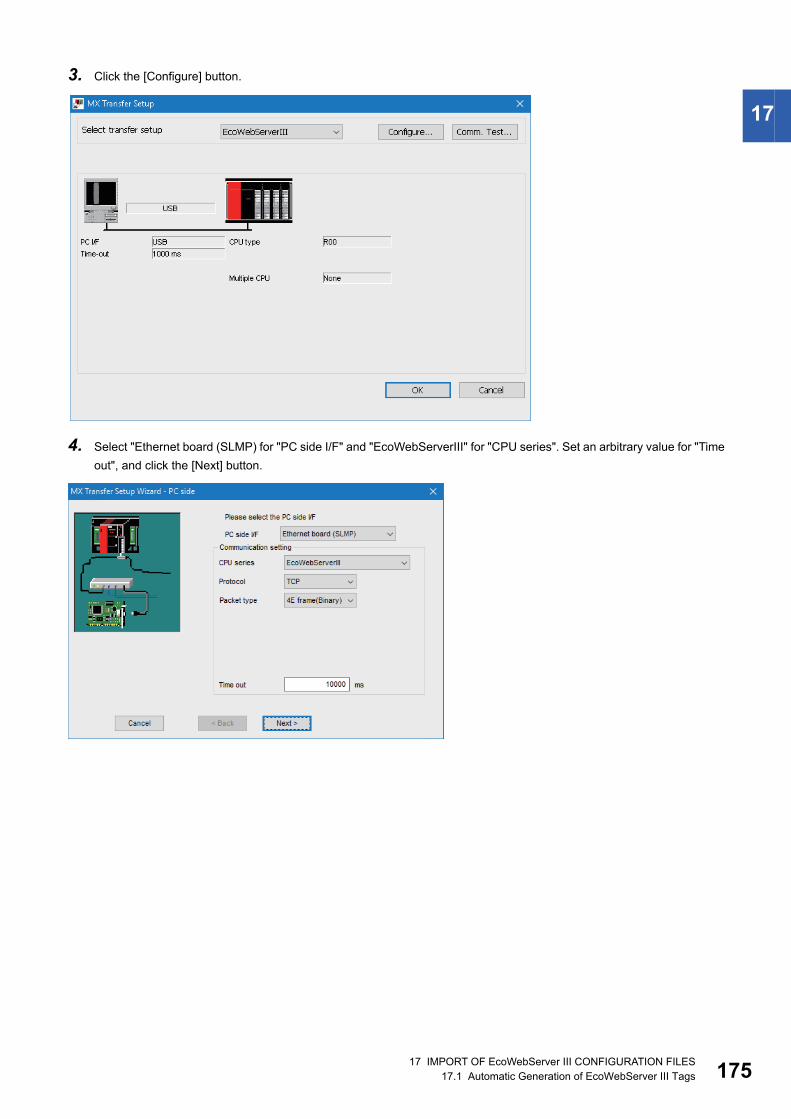
17 IMPORT OF EcoWebServer III CONFIGURATION FILES17.1 Automatic Generation of EcoWebServer III Tags 175
17
3. Click the [Configure] button.
4. Select "Ethernet board (SLMP) for "PC side I/F" and "EcoWebServerIII" for "CPU series". Set an arbitrary value for "Time
out", and click the [Next] button.

17617 IMPORT OF EcoWebServer III CONFIGURATION FILES17.1 Automatic Generation of EcoWebServer III Tags
5. Set an arbitrary value for "Host (IP Address)" and "CPU time out", and then click the [Next] button.
6. Set a comment, and click the [Finish] button.

17 IMPORT OF EcoWebServer III CONFIGURATION FILES17.1 Automatic Generation of EcoWebServer III Tags 177
17
7. Click the [OK] button.
8. Set each item in the "Device Properties" screen, and click the [Save] button.
For details on each item, refer to the following section.
Page 64 MX device screen setting

17817 IMPORT OF EcoWebServer III CONFIGURATION FILES17.1 Automatic Generation of EcoWebServer III Tags
9. When the import is succeeded, "Import completed successfully" is displayed in the "Import EcoWebServer III" screen.
If an error occurs, the error content will be displayed.
Click the [OK] button.
10. The message whether to save the setting appears. Click the [Yes] button.

17 IMPORT OF EcoWebServer III CONFIGURATION FILES17.2 Settings for Connecting to EcoWebServer III 179
1717.2 Settings for Connecting to EcoWebServer IIIThis section shows how to add a new connection to an EcoWebServer III without importing an EcoWebServer III configuration
file.
Operating procedure
1. Select "Address Space" in the tree view.
2. Select [Edit] [New MX Device] ( ).
3. Add a new connection destination in the "MX Transfer Setup" screen.
Page 78 Adding new connection destination settings
4. The procedure after the setting above is the same as the step 3 to 8 for importing an EcoWebServer III configuration file.
Page 174 Automatic Generation of EcoWebServer III Tags

18017 IMPORT OF EcoWebServer III CONFIGURATION FILES17.3 Tags for Demand Measurement Point
17.3 Tags for Demand Measurement PointWhen importing the setting of a device with the demand monitoring function, the tags for demand measurement point are
automatically generated.
A group name is created with "DemandInfomation".
The following table shows tag names for each item.
Device number Item Tag name Data type
D1000 Control device for monitoring ControlDeviceForMonitoring WORD
D1001 Healthy Healthy WORD
D1002 Current time Year CurrentTimeYear WORD
D1003 Month CurrentTimeMon WORD
D1004 Day CurrentTimeDays WORD
D1005 Time CurrentTimeHours WORD
D1006 Minute CurrentTimeMinute WORD
D1007 Second CurrentTimeSec WORD
D1008 Integrated value of consumption IntegratedValueOfConsumption DWORD
D1010 Current demand CurrentDemand DWORD
D1012 Predicted demand PredictedDemand DWORD
D1014 Adjusted electrical power AdjustedElectricalPower DWORD
D1016 Permissible power PermissiblePower DWORD
D1018 Previous demand PreviousDemand DWORD
D1020 Remaining time RemainingTime WORD
D1021 Alarm Alarm WORD
D1022 Control status ControlStatus WORD
D1023 Target demand TargetDemand DWORD
D1025 VCT ratio VCTRatio DWORD
D1027 Alarm type AlarmType WORD
D1028 Integrated value of consumption
Number of decimal digits
IntegratedValueOfConsumptionNumberOfDecimaldigits WORD
D1029 Demand Number of decimal digits CurrentDemand_NumberOfDecimalDigits WORD

18 IMPORT OF CSP+ (MACHINE PROFILE)18.1 Automatic Generation of Tags Using CSP+ (Machine Profile) 181
18
18 IMPORT OF CSP+ (MACHINE PROFILE)
Tags are automatically generated by importing CSP+ (machine profile).
Tags generated with the import function of CSP+ (machine profile) can only be used for Ethernet (SLMP) communication.
18.1 Automatic Generation of Tags Using CSP+ (Machine Profile)
This section shows the procedure to import CSP+ (machine profile).
Precautions
■Importing a large amount of data from CSP+ (machine profile)It takes time to import a large amount of data (more than 100000 data items, for example) by connecting MX OPC UA Server;
therefore, following the procedure below to import data is recommended.
1. Select [File] [Save to file] to save the setting locally (disconnected from Server).
2. Import CSP+ (machine profile).
3. Select [File] [Save to server] to save the setting to Server (reconnected to Server).
Operating procedure
1. Select [File] [CSP+(machine profile) actions] [Import CSP+(machine profile)].
2. The "Import CSP+(machine profile)" screen appears.
Click the [...] button to select CSP+ (machine profile) to import.
For details on each item in the screen, refer to the following section.
Page 184 Import CSP+ (Machine Profile) Screen

18218 IMPORT OF CSP+ (MACHINE PROFILE)18.1 Automatic Generation of Tags Using CSP+ (Machine Profile)
3. Click the [...] button in "Device Setting" of a device to add.
4. The "MX Transfer Setup" screen is displayed. Set a connection destination.
Set "Ethernet(SLMP)" for "PC Side I/F". For details, refer to the following section.
Page 77 Setting Connection Destinations
5. The "Device Properties" screen appears. Set each item in the screen.
Page 64 MX device screen setting
6. When the setting are properly configured, "Configuration" is displayed in "Device Setting".
Select machine data to import, and click the [OK] button.
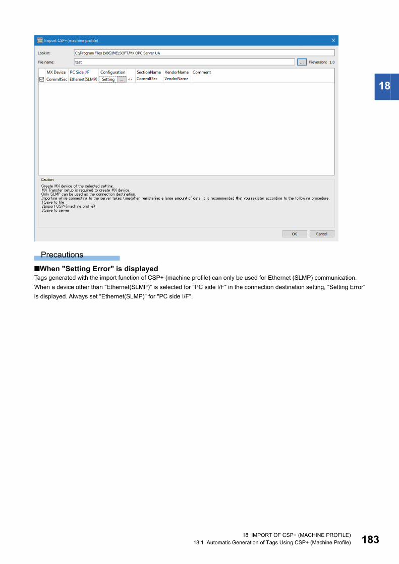
18 IMPORT OF CSP+ (MACHINE PROFILE)18.1 Automatic Generation of Tags Using CSP+ (Machine Profile) 183
18
Precautions
■When "Setting Error" is displayedTags generated with the import function of CSP+ (machine profile) can only be used for Ethernet (SLMP) communication.
When a device other than "Ethernet(SLMP)" is selected for "PC side I/F" in the connection destination setting, "Setting Error"
is displayed. Always set "Ethernet(SLMP)" for "PC side I/F".

18418 IMPORT OF CSP+ (MACHINE PROFILE)18.2 Import CSP+ (Machine Profile) Screen
18.2 Import CSP+ (Machine Profile) ScreenThis section shows the details of the "Import CSP+ (machine profile)" screen.
Window
Displayed items
Item Description
Look in A folder where import target CSP+ (machine profile) is stored is displayed.
File name The name of CSP+ (machine profile) to be imported is displayed.
[...] button Click this button to display the "Select the CSP+ (machine profile)" screen.
Select CSP+ (machine profile) to import, and click the [OK] button.
FileVersion The file version of CSP+ (machine profile) is displayed.
Device selection list Checkbox The tag of the selected machine data is generated.
MX Device The MX device name set in the "Device Properties" screen is displayed.
PC Side I/F The PC side I/F set in the "MX Transfer Setup Wizard" screen is displayed.
Configuration Any of the following status is displayed for the current status of the device.
• No Setting: No device is set.
• Setting: A device is set normally.
• Setting Error: A device other than "Ethernet(SLMP)" is set for "PC side I/F".
SectionName "LABEL" of "BLOCKINFO" described in CSP+ (machine profile) is displayed.
VendorName "VendorName" of "BLOCKINFO" described in CSP+ (machine profile) is displayed.
Comment "COMMENT" of "BLOCKINFO" described in CSP+ (machine profile) is displayed.
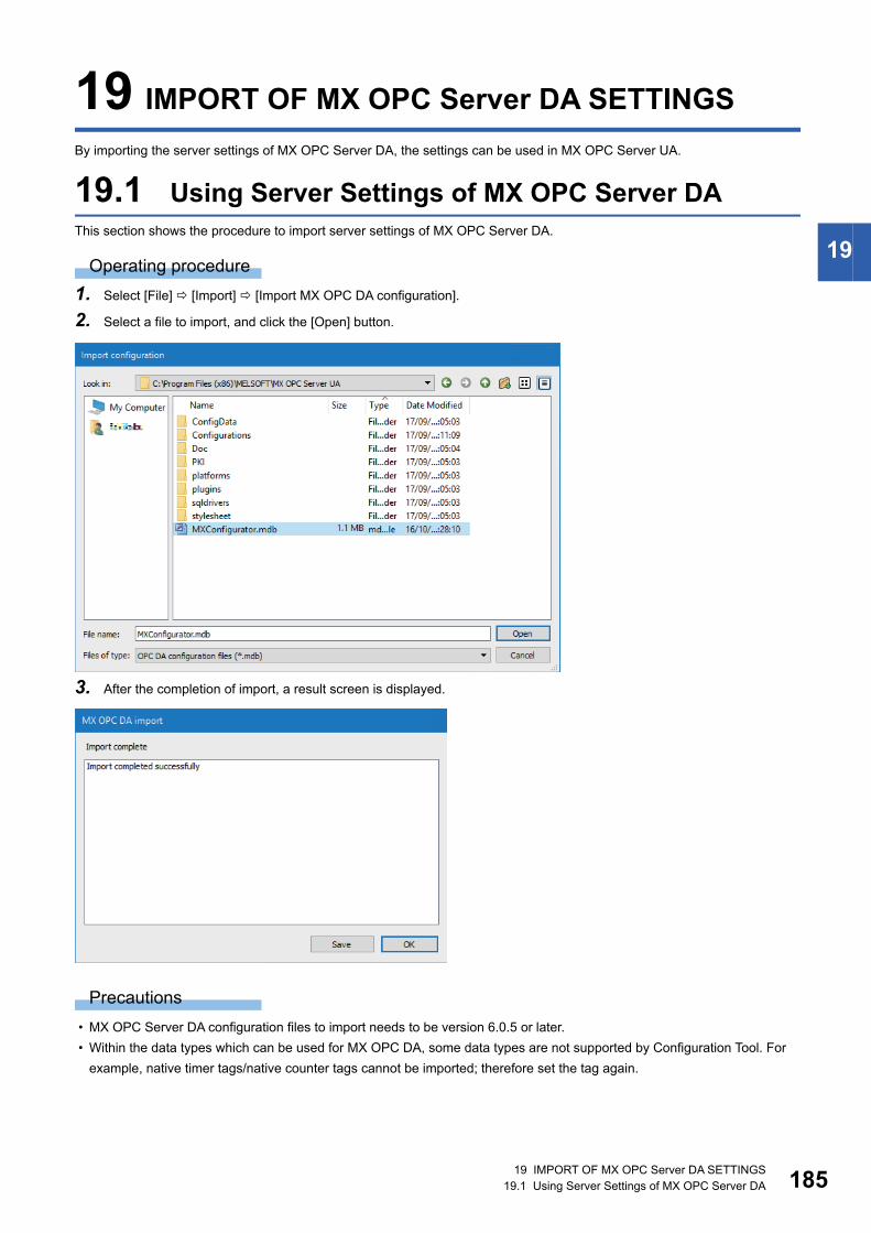
19 IMPORT OF MX OPC Server DA SETTINGS19.1 Using Server Settings of MX OPC Server DA 185
19
19 IMPORT OF MX OPC Server DA SETTINGS
By importing the server settings of MX OPC Server DA, the settings can be used in MX OPC Server UA.
19.1 Using Server Settings of MX OPC Server DAThis section shows the procedure to import server settings of MX OPC Server DA.
Operating procedure
1. Select [File] [Import] [Import MX OPC DA configuration].
2. Select a file to import, and click the [Open] button.
3. After the completion of import, a result screen is displayed.
Precautions
• MX OPC Server DA configuration files to import needs to be version 6.0.5 or later.
• Within the data types which can be used for MX OPC DA, some data types are not supported by Configuration Tool. For
example, native timer tags/native counter tags cannot be imported; therefore set the tag again.

18619 IMPORT OF MX OPC Server DA SETTINGS19.1 Using Server Settings of MX OPC Server DA
MEMO
187
PA
RT
3
PART 4 TROUBLESHOOTING
This part explains about troubleshooting.
20 TROUBLESHOOTING
21 ERROR CODES
18820 TROUBLESHOOTING
20 TROUBLESHOOTING
This chapter explains common problems and their corrective actions for MX OPC UA Server and Configuration Tool.
For errors other than ones listed below, refer to the following section.
Page 190 ERROR CODES
*1 The Windows version can be checked by the following procedure. Press Windows key + , or select [Windows System] [Run] from the Start menu of Windows. Enter 'winver' in the "Run" screen. Check the version in the displayed screen.
*2 The display of Configuration Tool will be blurred by enlarging.The following lists the setting values for "Change the size of text, apps, and other items" and the recommended display resolution for each setting value in Windows 10.Setting value: 100%, resolution of the display: 1024 768 dots or moreSetting value: 125%, resolution of the display: 1900 1200 dots or moreSetting value: 150%, resolution of the display: 1900 1200 dots or moreSetting value: 175%, resolution of the display: 2880 1620 dots or moreSetting value: 200%, resolution of the display: 2880 1620 dots or moreSetting value: 225%, resolution of the display: 3840 2160 dots or moreSetting value: 250%, resolution of the display: 3840 2160 dots or more
*3 'configtool.exe' is stored in the folder where Configuration Tool has been installed.The following is an example of a storage location.64-bit version operating system: C:\Program Files (x86)\MELSOFT\MX OPC Server UA\configtool.exe
Symptom Check point Corrective action
A client application cannot
communicate with a remote
server.
Is remote Server started?
Can remote Server be accessed?
• Start remote Server.
• Enter the URL of remote Server for "Endpoint Url" in the "Connection
settings" screen.
• Change the Windows firewall setting as necessary.
Are the certificates of a client application and
remote Server stored in the 'rejected' directory?
• Move the certificates to the 'trusted' or 'certs' directory. (The move
destination depends on the program.)
Is an old certificate with the same name stored? • Delete an old certificate.
Is a certificate expired? • Delete an expired certificate and create a new one.
Server cannot be registered
in remote discovery Server.
Is remote discovery Server started?
Can remote discovery Server be accessed?
• Start remote discovery Server.
• Enter the URL of remote discovery Server for "Discovery Url(s)" in the
"Connection settings" screen.
• Change the Windows firewall setting as necessary.
Was Server restarted after changing local Server
setting?
• If the setting is changed, restart Server.
Is a certificate stored in the 'rejected' directory? • Move the certificate to the 'trusted' or 'certs' directory. (The move
destination depends on the program.)
Does the certificate of remote discovery Server
exist in the 'certs' directory of Server to be
registered?
• Store the certificate of remote discovery Server in the 'certs' directory.
Is an old certificate with the same name stored? • Delete an old certificate.
Is a certificate expired? • Delete an expired certificate and create a new one.
The screen size of
Configuration Tool is
changed accidentally, and the
size cannot be restored to
default.
Delete a configuration file to reset the layout.
Note that, however, all settings including window layout, display/hide
status of toolbars and columns, and column width are also reset.
• Close Configuration Tool.
• Start Explorer (by pressing the Windows key + key) and enter the
following in the address bar.
'%appdata%\Mitsubishi'. Rename or delete the file 'MX OPCUA
Configurator.ini'
• Restart Configuration Tool.
Contents in the screen may
not be displayed properly.
(For example, overlapping of
icons, text overflowing from
the flame of a button, etc.)
Is the size of the text and/or other items in the
screen changed to a value other than the default
value (such as 96 DPI, 100%, and 9 pt) in
Windows settings?
• Return the settings to the defaults.
• For Windows 10 (version 1703 or later)*1, the display of Configuration
Tool can be enlarged with high DPI scaling by using a Windows 10
function*2.
Select 'configtool.exe'*3, then select [Properties] on the right-click
menu.
Select "Override high DPI scaling behavior. Scaling performed by:" in
the [Compatibility] tab, then select "System" from the pull-down list.
Click the [OK] button.

20 TROUBLESHOOTING 189
20
32-bit version operating system: C:\Program Files\MELSOFT\MX OPC Server UA\configtool.exe

19021 ERROR CODES
21 ERROR CODES
This chapter explains the error descriptions and corrective actions for each error code.
When an error occurred, the detailed error code is displayed in the log view, or "Last Transaction Status" in the "Statistics"
screen.
Error codes are classified into the following three types:
Error code Description Reference
HRESULT error code A general error code which is displayed regardless of the setting
of a device and its status.
Page 191 HRESULT error codes
Server error code An error code returned from Server. Page 192 Server error codes
Error code in a connection destination
device
An error code returned from a specific device. Page 216 Error codes in a connection
destination device

21 ERROR CODES21.1 Server Error Codes 191
21
21.1 Server Error Codes
HRESULT error codesThe following table shows general ActiveX errors.
HRESULT error codes are not necessarily related to the setting or status of a device.
Value Name Type Description
0x00000000 S_OK Normal termination The function processing is normally terminated.
0x00000001 S_FALSE Normal termination The function processing (as ActiveX control) is normally terminated, but
the operation (access to programmable controller) failed.
0x80004003 E_POINTER Abnormal termination The pointer passed to the function is invalid.
0x80070006 E_HANDLE Abnormal termination A supplied handle value is invalid.
0x8007000E E_OUTOFMEMORY Abnormal termination Memory assignment or object creation failed.
0x80070057 E_INVALIDARG Abnormal termination An incorrect argument was passed.
0x80070005 E_ACCESSDENIED Abnormal termination Permission to use the object is insufficient.
0x8000FFFF E_UNEXPECTED Abnormal termination An unexpected error occurred.
0x80004005 E_FAIL Abnormal termination An unspecified error occurred.
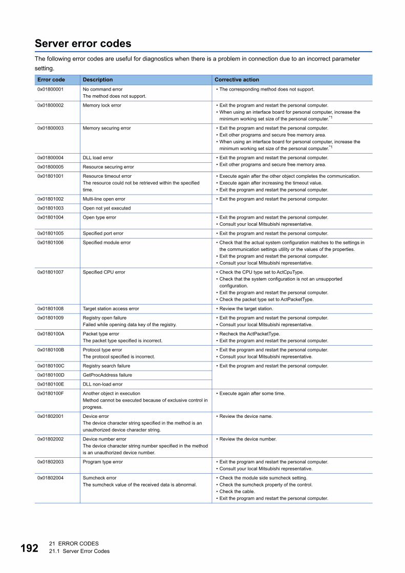
19221 ERROR CODES21.1 Server Error Codes
Server error codesThe following error codes are useful for diagnostics when there is a problem in connection due to an incorrect parameter
setting.
Error code Description Corrective action
0x01800001 No command error
The method does not support.
• The corresponding method does not support.
0x01800002 Memory lock error • Exit the program and restart the personal computer.
• When using an interface board for personal computer, increase the
minimum working set size of the personal computer.*1
0x01800003 Memory securing error • Exit the program and restart the personal computer.
• Exit other programs and secure free memory area.
• When using an interface board for personal computer, increase the
minimum working set size of the personal computer.*1
0x01800004 DLL load error • Exit the program and restart the personal computer.
• Exit other programs and secure free memory area.0x01800005 Resource securing error
0x01801001 Resource timeout error
The resource could not be retrieved within the specified
time.
• Execute again after the other object completes the communication.
• Execute again after increasing the timeout value.
• Exit the program and restart the personal computer.
0x01801002 Multi-line open error • Exit the program and restart the personal computer.
0x01801003 Open not yet executed
0x01801004 Open type error • Exit the program and restart the personal computer.
• Consult your local Mitsubishi representative.
0x01801005 Specified port error • Exit the program and restart the personal computer.
0x01801006 Specified module error • Check that the actual system configuration matches to the settings in
the communication settings utility or the values of the properties.
• Exit the program and restart the personal computer.
• Consult your local Mitsubishi representative.
0x01801007 Specified CPU error • Check the CPU type set to ActCpuType.
• Check that the system configuration is not an unsupported
configuration.
• Exit the program and restart the personal computer.
• Check the packet type set to ActPacketType.
0x01801008 Target station access error • Review the target station.
0x01801009 Registry open failure
Failed while opening data key of the registry.
• Exit the program and restart the personal computer.
• Consult your local Mitsubishi representative.
0x0180100A Packet type error
The packet type specified is incorrect.
• Recheck the ActPacketType.
• Exit the program and restart the personal computer.
0x0180100B Protocol type error
The protocol specified is incorrect.
• Exit the program and restart the personal computer.
• Consult your local Mitsubishi representative.
0x0180100C Registry search failure • Exit the program and restart the personal computer.
0x0180100D GetProcAddress failure
0x0180100E DLL non-load error
0x0180100F Another object in execution
Method cannot be executed because of exclusive control in
progress.
• Execute again after some time.
0x01802001 Device error
The device character string specified in the method is an
unauthorized device character string.
• Review the device name.
0x01802002 Device number error
The device character string number specified in the method
is an unauthorized device number.
• Review the device number.
0x01802003 Program type error • Exit the program and restart the personal computer.
• Consult your local Mitsubishi representative.
0x01802004 Sumcheck error
The sumcheck value of the received data is abnormal.
• Check the module side sumcheck setting.
• Check the sumcheck property of the control.
• Check the cable.
• Exit the program and restart the personal computer.
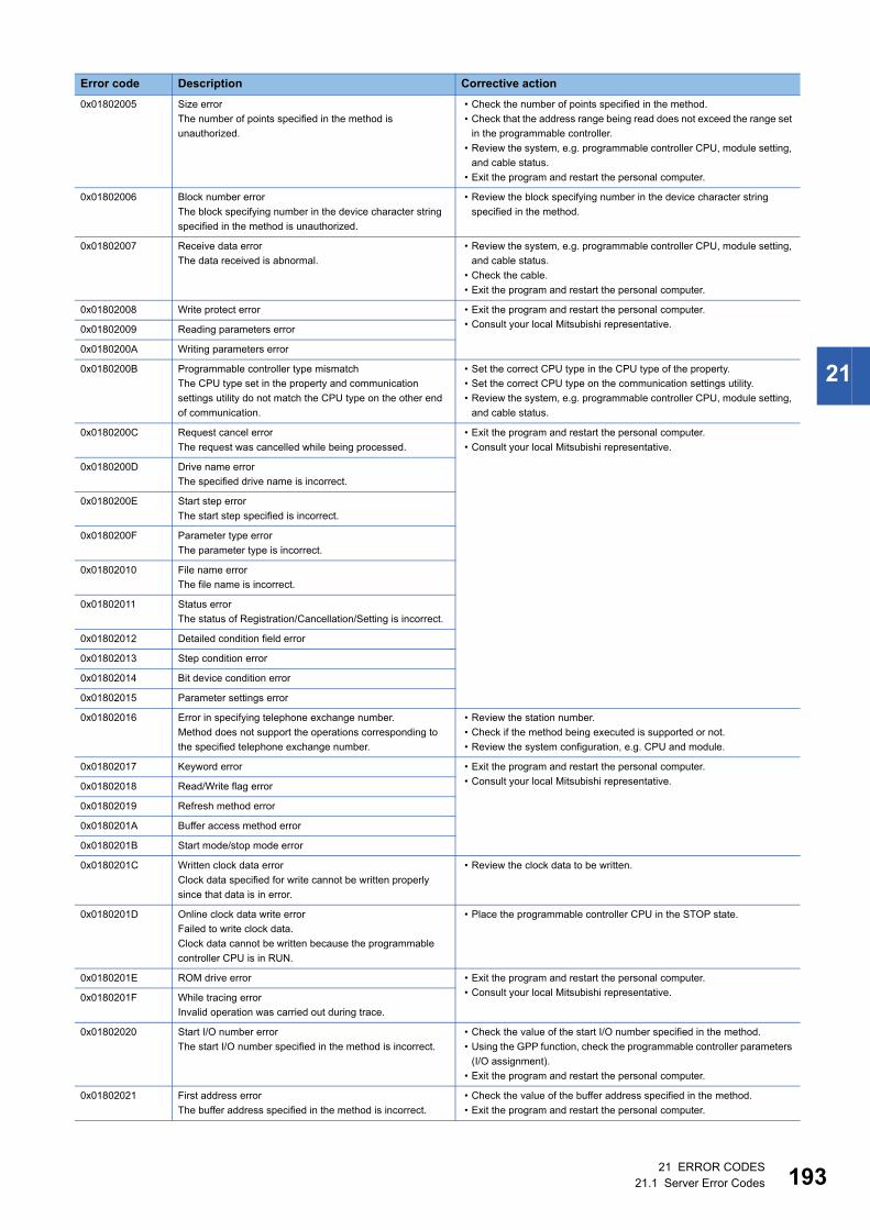
21 ERROR CODES21.1 Server Error Codes 193
21
0x01802005 Size error
The number of points specified in the method is
unauthorized.
• Check the number of points specified in the method.
• Check that the address range being read does not exceed the range set
in the programmable controller.
• Review the system, e.g. programmable controller CPU, module setting,
and cable status.
• Exit the program and restart the personal computer.
0x01802006 Block number error
The block specifying number in the device character string
specified in the method is unauthorized.
• Review the block specifying number in the device character string
specified in the method.
0x01802007 Receive data error
The data received is abnormal.
• Review the system, e.g. programmable controller CPU, module setting,
and cable status.
• Check the cable.
• Exit the program and restart the personal computer.
0x01802008 Write protect error • Exit the program and restart the personal computer.
• Consult your local Mitsubishi representative.0x01802009 Reading parameters error
0x0180200A Writing parameters error
0x0180200B Programmable controller type mismatch
The CPU type set in the property and communication
settings utility do not match the CPU type on the other end
of communication.
• Set the correct CPU type in the CPU type of the property.
• Set the correct CPU type on the communication settings utility.
• Review the system, e.g. programmable controller CPU, module setting,
and cable status.
0x0180200C Request cancel error
The request was cancelled while being processed.
• Exit the program and restart the personal computer.
• Consult your local Mitsubishi representative.
0x0180200D Drive name error
The specified drive name is incorrect.
0x0180200E Start step error
The start step specified is incorrect.
0x0180200F Parameter type error
The parameter type is incorrect.
0x01802010 File name error
The file name is incorrect.
0x01802011 Status error
The status of Registration/Cancellation/Setting is incorrect.
0x01802012 Detailed condition field error
0x01802013 Step condition error
0x01802014 Bit device condition error
0x01802015 Parameter settings error
0x01802016 Error in specifying telephone exchange number.
Method does not support the operations corresponding to
the specified telephone exchange number.
• Review the station number.
• Check if the method being executed is supported or not.
• Review the system configuration, e.g. CPU and module.
0x01802017 Keyword error • Exit the program and restart the personal computer.
• Consult your local Mitsubishi representative.0x01802018 Read/Write flag error
0x01802019 Refresh method error
0x0180201A Buffer access method error
0x0180201B Start mode/stop mode error
0x0180201C Written clock data error
Clock data specified for write cannot be written properly
since that data is in error.
• Review the clock data to be written.
0x0180201D Online clock data write error
Failed to write clock data.
Clock data cannot be written because the programmable
controller CPU is in RUN.
• Place the programmable controller CPU in the STOP state.
0x0180201E ROM drive error • Exit the program and restart the personal computer.
• Consult your local Mitsubishi representative.0x0180201F While tracing error
Invalid operation was carried out during trace.
0x01802020 Start I/O number error
The start I/O number specified in the method is incorrect.
• Check the value of the start I/O number specified in the method.
• Using the GPP function, check the programmable controller parameters
(I/O assignment).
• Exit the program and restart the personal computer.
0x01802021 First address error
The buffer address specified in the method is incorrect.
• Check the value of the buffer address specified in the method.
• Exit the program and restart the personal computer.
Error code Description Corrective action

19421 ERROR CODES21.1 Server Error Codes
0x01802022 Pattern error • Exit the program and restart the personal computer.
• Consult your local Mitsubishi representative.0x01802023 SFC block No. error
0x01802024 SFC step number error
0x01802025 Step number error
0x01802026 Data error
0x01802027 System data error
0x01802028 Error in number of TC settings value
0x01802029 Clear mode error
0x0180202A Signal flow error
0x0180202B Version management error
0x0180202C Monitor not registered error
0x0180202D PI type error
0x0180202E PI number error
0x0180202F Error in number of PIs
0x01802030 Shift error
0x01802031 File type error
0x01802032 Specified module error
0x01802033 Error check flag error
0x01802034 Step RUN operation error
0x01802035 Step RUN data error
0x01802036 During step RUN error
0x01802037 Write error while running program corresponding to E2ROM
0x01802038 Clock data read/write error
The clock data read/write method was executed for a
programmable controller CPU which does not have clock
data.
• Do not execute clock data read/write.
0x01802039 Trace not completed error • Exit the program and restart the personal computer.
• Consult your local Mitsubishi representative.0x0180203A Registration clear flag error
0x0180203B Operation error
0x0180203C Error in the number of exchanges
0x0180203D Error in number of loops specified
0x0180203E Retrieve data selection
0x0180203F Error in number of SFC cycles
0x01802040 Motion programmable controller error
0x01802041 Motion programmable controller communication error
0x01802042 Fixed execution time setting error
0x01802043 Error in number of functions
0x01802044 System information specification error
0x01802045 Registration condition not formed error
Error code Description Corrective action

21 ERROR CODES21.1 Server Error Codes 195
21
0x01802046 Function number error • Exit the program and restart the personal computer.
• Consult your local Mitsubishi representative.0x01802047 RAM drive error
0x01802048 ROM drive error at the booting side
0x01802049 Transfer mode specification error at the booting side
0x0180204A Insufficient memory error
0x0180204B Back up drive ROM error
0x0180204C Block size error
0x0180204D Detached during RUN state error
0x0180204E Module already registered error
0x0180204F Password registration data full error
0x01802050 Password not registered error
0x01802051 Remote password error
0x01802052 IP address error
0x01802053 Timeout value out of range error
0x01802054 Command not detected error
0x01802055 Trace execution type error
0x01802056 Version error
0x01802057 Tracking cable error
The tracking cable is faulty.
The programmable controller CPU is in error.
• Review the system, e.g. programmable controller CPU, module setting,
and cable status.
0x0180205C Keyword protection error
The programmable controller CPU is protected by a
keyword.
• Disable the keyword and execute again.
0x0180205D Keyword disable error
The inputted keyword is wrong.
• Input a correct keyword.
0x0180205E Keyword protecting error
The programmable controller CPU did not accept the
command.
• Execute keyword protection again, or cycle the power of the
programmable controller CPU again.
0x0180205F Keyword entry error
An illegal character is included in the inputted keyword.
• Input a correct keyword.
0x01802060 Keyword deletion error
The inputted keyword is wrong.
0x01802062 Received packet CRC check error
An error occurred in CRC check for receive packet data.
• Execute the communication process again.
0x01802063 Received packet CRC check error
An error occurred in CRC check for whole data file of
receive packet.
0x01802064 FX series programmable controller connection error • Consult your local Mitsubishi representative.
0x01802070 Online change program error
No target program for online change exists in the
programmable controller CPU.
• Execute the online change after changing the programmable controller
CPU status to STOP.
0x01802071 Ether direct communication multiple response receive error
Multiple responses were received during Ether direct
communication.
• Check if the personal computer and the programmable controller CPU
are connected on a one-to-one basis.
0x01802072 Ether direct communication error
Unable to communicate because the programmable
controller CPU is being accessed by another personal
computer during Ether direct communication.
0x01802073 Programmable controller CPU search response error
When a programmable controller CPU search is performed,
the number of responses exceeded the maximum number to
be searched.
• Reduce the number of programmable controller CPUs on the network to
1024 or less.
0x01802074 Redundant system other system connection diagnostics
error
• Disconnect the cable and connect it to the currently disconnected
programmable controller CPU.
• Or, change the redundant CPU specification to the self system.
0x01808001 Multiple Open error
Open method was executed while in Open state.
• Exit the program and restart the personal computer.
• Execute any method other than Open.
0x01808002 Channel number specifying error
The port number set to the property and the port number set
on the communication settings utility are incorrect.
• Set the correct value to the port number of the property.
• Set it again on the communication settings utility.
Error code Description Corrective action

19621 ERROR CODES21.1 Server Error Codes
0x01808003 Driver not yet started
The network board driver is not started.
• Start the driver.
0x01808004 Error in overlap event generation • Exit the program and restart the personal computer.
• Consult your local Mitsubishi representative.
0x01808005 MUTEX generation error
Failed in creation of MUTEX to perform exclusive control.
• Exit the program and restart the personal computer.
0x01808006 Error in socket object generation
A Socket object could not be created.
• Exit the program and restart the personal computer.
• Consult your local Mitsubishi representative.
0x01808007 Socket object generation error
Failed in creating a Socket object.
• Check for a running application which uses the same port number.
• Retry after changing the port number value of the property.
• Retry after changing the port number value on the communication
settings utility.
• Make Ethernet board and protocol settings on the control panel of the
OS.
• Exit the program and restart the personal computer.
• Consult your local Mitsubishi representative.
0x01808008 Port connection error
Failed to establish connection.
The other end does not respond.
• Review the values of the IP address and port number of the properties.
• Review the value of the port number in the communication settings
utility.
• Review the system, e.g. programmable controller CPU, module setting,
and cable status.
• Exit the program and restart the personal computer.
0x01808009 COM port handle error
Unable to acquire the handle of the COM port.
Unable to copy the COM port object.
Unable to copy the SOCKET object.
• Check for an application which uses the COM port.
• Exit the program and restart the personal computer.
0x0180800A Buffer size setting error
Failed in setting COM port buffer size.
• Check for an application which uses the COM port.
• Configure the COM port setting in the control panel of the operating
system.
• Exit the program and restart the personal computer.0x0180800B DCB value acquisition error
Failed in acquiring a COM port DCB value.
0x0180800C DCB setting error
Failed in setting a COM port DCB value.
0x0180800D Time-out value setting error
Failed in setting a COM port time-out value.
• Review the time-out value of the property.
• Review the time-out value on the communication settings utility.
• Check for an application which uses the COM port.
• Configure the COM port setting in the control panel of the operating
system.
• Exit the program and restart the personal computer.
0x0180800E Shared memory open error
Failed to execute open processing of shared memory.
• Check whether the GX Simulator has started.
• Exit the program and restart the personal computer.
0x01808101 Duplex close error • Exit the program and restart the personal computer.
0x01808102 Handle close error
Failed in closing the COM port handle.
0x01808103 Driver close error
Failed in closing the driver handle.
0x01808104 Overlap event close error • Exit the program and restart the personal computer.
• Consult your local Mitsubishi representative.0x01808105 Mutex handle close error
0x01808106 COM port handle close error
0x01808201 Send error
Failed to send data.
• Review the system, e.g. programmable controller CPU, module setting,
and cable status.
• Configure the COM port setting in the control panel of the operating
system.
• Configure the settings of Ethernet board and protocol in the control
panel.
• Retry the method.
• Exit the program and restart the personal computer.
0x01808202 Send data size error
Failed to send data.
• Exit the program and restart the personal computer.
0x01808203 Queue clear error
Failed in clearing a COM port queue.
• Exit the program and restart the personal computer.
• Execute Close once and execute Open again.
Error code Description Corrective action

21 ERROR CODES21.1 Server Error Codes 197
21
0x01808301 Receive error
Failed to receive data.
• Review the system, e.g. programmable controller CPU, module setting,
and cable status.
• Review the time-out value of the property.
• Review the time-out value on the communication settings utility.
• Retry the method.
• Exit the program and restart the personal computer.
0x01808302 Not sent error • Exit the program and restart the personal computer.
• Consult your local Mitsubishi representative.0x01808303 Error in retrieving overlap event
0x01808304 Receive buffer size shortage
Receive data was larger than the receive buffer size
prepared for the system.
• Exit the program and restart the personal computer.
0x01808401 Control error
Failed in changing a COM port communication control.
0x01808402 Signal line control error • Exit the program and restart the personal computer.
• Consult your local Mitsubishi representative.
0x01808403 Signal line specifying error
Failed in changing a COM port communication control.
• Exit the program and restart the personal computer.
0x01808404 Open not yet executed • Execute Open.
• Exit the program and restart the personal computer.
0x01808405 Communication parameter error
The data bit and stop bit combination of the properties is
unauthorized.
• Review the data bit and stop bit values of the properties.
• Set it again on the communication settings utility.
0x01808406 Transmission speed value specifying error
The transmission speed of the property is unauthorized.
• Review the transmission speed value of the property.
• Set it again on the communication settings utility.
0x01808407 Data length error
The data bit value of the property is unauthorized.
• Review the data bit value of the property.
• Set it again on the communication settings utility.
0x01808408 Parity specifying error
The parity value of the property is unauthorized.
• Review the parity value of the property.
• Set it again on the communication settings utility.
0x01808409 Stop bit specifying error
The stop bit value of the property is unauthorized.
• Review the stop bit value of the property.
• Set it again on the communication settings utility.
0x0180840A Communication control setting error
The control value of the property is unauthorized.
• Review the control value of the property.
• Set it again on the communication settings utility.
0x0180840B Time-out error
Though the time-out period had elapsed, data could not be
received.
• Review the time-out value of the property.
• Set it again on the communication settings utility.
• Review the system, e.g. programmable controller CPU, module setting,
and cable status.
• Retry the method.
• Execute Close once and execute Open again.
• Exit the program and restart the personal computer.
0x0180840C Connect error • Exit the program and restart the personal computer.
0x0180840D Duplex connect error
0x0180840E Attach failure
Failed in attaching a socket object.
0x0180840F Signal line status acquisition failure
Failed in acquiring the COM port signal line status.
0x01808410 CD signal line OFF
The CD signal on the other end of communication is OFF.
• Review the system, e.g. programmable controller CPU, module setting,
and cable status.
• Exit the program and restart the personal computer.
0x01808411 Password mismatch error • Check the remote password of the property.
0x01808412 TEL communication error • Exit the program and restart the personal computer.
• Consult your local Mitsubishi representative.
0x01808501 USB driver load error
Failed to load USB driver.
• Exit the program and restart the personal computer.
• Check USB driver installation.
0x01808502 USB driver connect error
Failed to connect a USB driver.
0x01808503 USB driver send error
Failed to send data.
• Review the system, e.g. programmable controller CPU, module setting,
and cable status.
• Configure the USB setting on the control panel (device manager) of the
operating system.
• Retry the method.
• Exit the program and restart the personal computer.
0x01808504 USB driver receive error
Failed to receive data.
Error code Description Corrective action

19821 ERROR CODES21.1 Server Error Codes
0x01808505 USB driver timeout error • Review the timeout value.
• Exit the program and restart the personal computer.
• Consult your local Mitsubishi representative.
0x01808506 USB driver initialization error
Failed to initialize a USB driver.
• Configure the USB setting on the control panel (device manager) of the
operating system.
• Exit the program and restart the personal computer.
0x01808507 Other USB error
Error related to data send/receive occurred.
• Disconnect the cable once, then reconnect.
• Exit the program and restart the personal computer.
0x01809000 GX Simulator2 uninstallation error
An error occurred when searching the installation path of GX
Simulator2.
• Reinstall GX Simulator2.
0x01809001 GX Simulator2 unstart error
GX Simulator2 is not started.
• Start GX Simulator2.
0x01809002 GX Simulator2 start error • Exit the program and restart the personal computer.
• Consult your local Mitsubishi representative.0x01809003 GX Simulator2 start time-out error
0x01809004 GX Simulator2 stop error
0x01809005 GX Simulator2 start error
0x01809007 GX Simulator2 stop error
0x01809008 GX Simulator2 start error
Because it had reached upper bounds of the number of
simulations that was able to be started at the same time, it
was not possible to start.
0x01809009 GX Simulator2 start error
The simulation of only one project that can be started has
started.
0x01809010 GX Simulator2 start information illegal error
An error occurred because the memory area to allocate GX
Simulator2 start information could not be acquired.
0x01809021 GX Simulator2 start error
Because it had reached upper bounds of the number of
simulations that was able to be started at the same time, it
was not possible to start.
0x01809022 GX Simulator2 start error
The simulation of another CPU was not able to begin
because the simulation of the FXCPU project had already
been begun.
0x02000001 Points exceeded error
The number of points registered in the monitoring server is
very high.
• Reduce the number of points registered by the monitor.
• Exit the program and restart the personal computer.
• Consult your local Mitsubishi representative.
0x02000002 Shared memory creation error
Failed in creating shared memory.
• Exit the program and restart the personal computer.
• Consult your local Mitsubishi representative.
0x02000003 Shared memory access error
0x02000004 Memory securing error
Failed in securing memory for the monitoring server.
• Close the other applications.
• Increase the system memory.
• Exit the program and restart the personal computer.
• Consult your local Mitsubishi representative.
0x02000005 Device not registered error
Monitor has not been registered.
• Register the monitor in the monitoring server.
• Exit the program and restart the personal computer.
• Consult your local Mitsubishi representative.
0x02000006 Monitoring server startup error
Monitoring server is not started.
• Start the monitoring server.
• Exit the program and restart the personal computer.
• Consult your local Mitsubishi representative.
0x02000010 Yet to retrieve device value error
Monitoring is not yet completed.
• Try to retrieve the value again after waiting for a fixed amount of time.
• Exit the program and restart the personal computer.
• Consult your local Mitsubishi representative.
Error code Description Corrective action
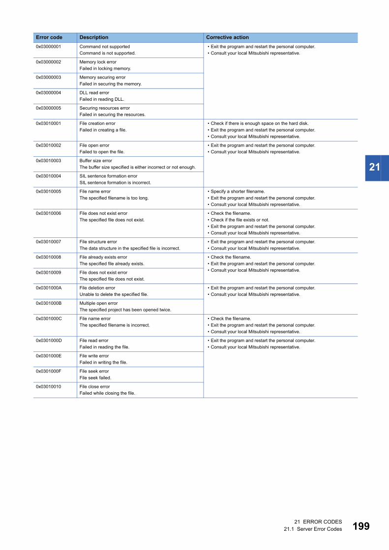
21 ERROR CODES21.1 Server Error Codes 199
21
0x03000001 Command not supported
Command is not supported.
• Exit the program and restart the personal computer.
• Consult your local Mitsubishi representative.
0x03000002 Memory lock error
Failed in locking memory.
0x03000003 Memory securing error
Failed in securing the memory.
0x03000004 DLL read error
Failed in reading DLL.
0x03000005 Securing resources error
Failed in securing the resources.
0x03010001 File creation error
Failed in creating a file.
• Check if there is enough space on the hard disk.
• Exit the program and restart the personal computer.
• Consult your local Mitsubishi representative.
0x03010002 File open error
Failed to open the file.
• Exit the program and restart the personal computer.
• Consult your local Mitsubishi representative.
0x03010003 Buffer size error
The buffer size specified is either incorrect or not enough.
0x03010004 SIL sentence formation error
SIL sentence formation is incorrect.
0x03010005 File name error
The specified filename is too long.
• Specify a shorter filename.
• Exit the program and restart the personal computer.
• Consult your local Mitsubishi representative.
0x03010006 File does not exist error
The specified file does not exist.
• Check the filename.
• Check if the file exists or not.
• Exit the program and restart the personal computer.
• Consult your local Mitsubishi representative.
0x03010007 File structure error
The data structure in the specified file is incorrect.
• Exit the program and restart the personal computer.
• Consult your local Mitsubishi representative.
0x03010008 File already exists error
The specified file already exists.
• Check the filename.
• Exit the program and restart the personal computer.
• Consult your local Mitsubishi representative.0x03010009 File does not exist error
The specified file does not exist.
0x0301000A File deletion error
Unable to delete the specified file.
• Exit the program and restart the personal computer.
• Consult your local Mitsubishi representative.
0x0301000B Multiple open error
The specified project has been opened twice.
0x0301000C File name error
The specified filename is incorrect.
• Check the filename.
• Exit the program and restart the personal computer.
• Consult your local Mitsubishi representative.
0x0301000D File read error
Failed in reading the file.
• Exit the program and restart the personal computer.
• Consult your local Mitsubishi representative.
0x0301000E File write error
Failed in writing the file.
0x0301000F File seek error
File seek failed.
0x03010010 File close error
Failed while closing the file.
Error code Description Corrective action
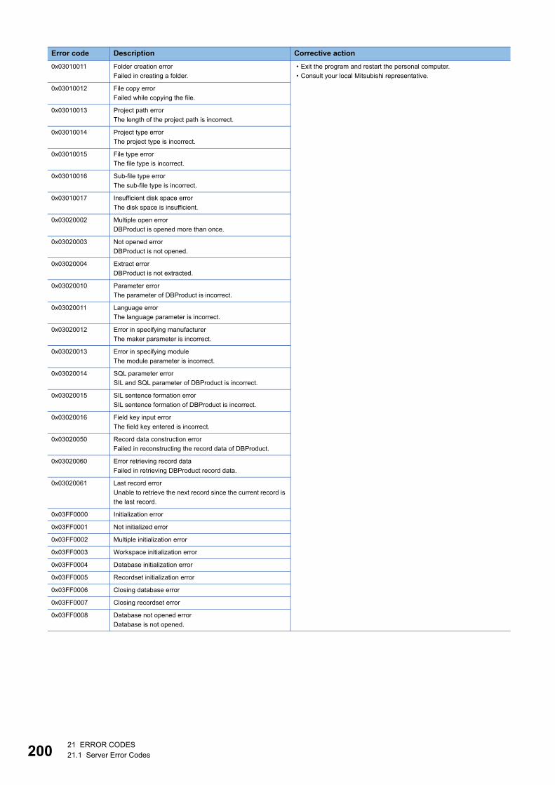
20021 ERROR CODES21.1 Server Error Codes
0x03010011 Folder creation error
Failed in creating a folder.
• Exit the program and restart the personal computer.
• Consult your local Mitsubishi representative.
0x03010012 File copy error
Failed while copying the file.
0x03010013 Project path error
The length of the project path is incorrect.
0x03010014 Project type error
The project type is incorrect.
0x03010015 File type error
The file type is incorrect.
0x03010016 Sub-file type error
The sub-file type is incorrect.
0x03010017 Insufficient disk space error
The disk space is insufficient.
0x03020002 Multiple open error
DBProduct is opened more than once.
0x03020003 Not opened error
DBProduct is not opened.
0x03020004 Extract error
DBProduct is not extracted.
0x03020010 Parameter error
The parameter of DBProduct is incorrect.
0x03020011 Language error
The language parameter is incorrect.
0x03020012 Error in specifying manufacturer
The maker parameter is incorrect.
0x03020013 Error in specifying module
The module parameter is incorrect.
0x03020014 SQL parameter error
SIL and SQL parameter of DBProduct is incorrect.
0x03020015 SIL sentence formation error
SIL sentence formation of DBProduct is incorrect.
0x03020016 Field key input error
The field key entered is incorrect.
0x03020050 Record data construction error
Failed in reconstructing the record data of DBProduct.
0x03020060 Error retrieving record data
Failed in retrieving DBProduct record data.
0x03020061 Last record error
Unable to retrieve the next record since the current record is
the last record.
0x03FF0000 Initialization error
0x03FF0001 Not initialized error
0x03FF0002 Multiple initialization error
0x03FF0003 Workspace initialization error
0x03FF0004 Database initialization error
0x03FF0005 Recordset initialization error
0x03FF0006 Closing database error
0x03FF0007 Closing recordset error
0x03FF0008 Database not opened error
Database is not opened.
Error code Description Corrective action

21 ERROR CODES21.1 Server Error Codes 201
21
0x03FF0009 Recordset not opened error
Recordset is not opened.
• Exit the program and restart the personal computer.
• Consult your local Mitsubishi representative.
0x03FF000A Table initialization error
Failed in initializing TtableInformation table.
0x03FF000B Table initialization error
Failed in initializing TfieldInformation table.
0x03FF000C Table initialization error
Failed in initializing TrelationInformation table.
0x03FF000D Table initialization error
Failed in initializing Tlanguage table.
0x03FF000E Table initialization error
Failed in initializing Tmaker table.
0x03FF000F Table initialization error
Failed in initializing TOpenDatabase table.
0x03FF0010 Field value error
0x03FF0011 Field value error
0x03FF0012 Exit error
Failed to exit the database.
0x03FF0100 Moving record error
Failed while moving the record.
0x03FF0101 Record count retrieving error
Failed to retrieve the record count.
0x03FF0110 Field value retrieving error
Failed in retrieving the field value.
0x03FF0111 Field value setting error
Failed in setting the field value.
0x03FFFFFF Other errors
0x04000001 No command error
The specified CPU type cannot be used to perform
processing.
• Check the CPU type set to ActCpuType.
• Check whether the system configuration is supported or not.
• Exit the program and restart the personal computer.
0x04000002 Memory lock error
Failed in locking memory.
• Exit the program and restart the personal computer.
• Consult your local Mitsubishi representative.
0x04000003 Memory securing error
Failed in securing the memory.
0x04000004 Internal server DLL load error
Failed to start an internal server.
0x04000005 Securing resources error
Failed in securing the resources.
0x04000006 Loading main object error
Failed in reading the file.
0x04000007 Loading conversion table error
Failed in reading table data.
0x04000100 Incorrect intermediate code size error
0x04010001 Intermediate code not converted error
The converted machine code for one command has
exceeded 256 bytes.
0x04010002 Intermediate code completion error
Intermediate code area of the code to be converted ended
abruptly.
0x04010003 Insufficient intermediate code error
The intermediate code of the code to be converted was
insufficient.
0x04010004 Intermediate code data error
The intermediate code to be converted is incorrect.
Error code Description Corrective action
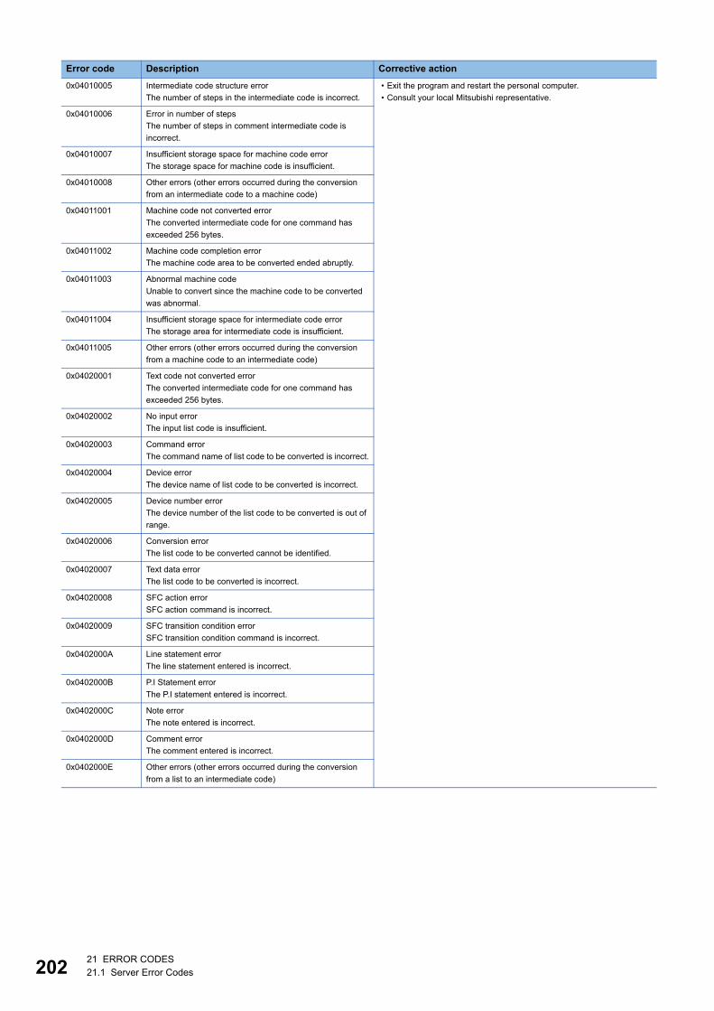
20221 ERROR CODES21.1 Server Error Codes
0x04010005 Intermediate code structure error
The number of steps in the intermediate code is incorrect.
• Exit the program and restart the personal computer.
• Consult your local Mitsubishi representative.
0x04010006 Error in number of steps
The number of steps in comment intermediate code is
incorrect.
0x04010007 Insufficient storage space for machine code error
The storage space for machine code is insufficient.
0x04010008 Other errors (other errors occurred during the conversion
from an intermediate code to a machine code)
0x04011001 Machine code not converted error
The converted intermediate code for one command has
exceeded 256 bytes.
0x04011002 Machine code completion error
The machine code area to be converted ended abruptly.
0x04011003 Abnormal machine code
Unable to convert since the machine code to be converted
was abnormal.
0x04011004 Insufficient storage space for intermediate code error
The storage area for intermediate code is insufficient.
0x04011005 Other errors (other errors occurred during the conversion
from a machine code to an intermediate code)
0x04020001 Text code not converted error
The converted intermediate code for one command has
exceeded 256 bytes.
0x04020002 No input error
The input list code is insufficient.
0x04020003 Command error
The command name of list code to be converted is incorrect.
0x04020004 Device error
The device name of list code to be converted is incorrect.
0x04020005 Device number error
The device number of the list code to be converted is out of
range.
0x04020006 Conversion error
The list code to be converted cannot be identified.
0x04020007 Text data error
The list code to be converted is incorrect.
0x04020008 SFC action error
SFC action command is incorrect.
0x04020009 SFC transition condition error
SFC transition condition command is incorrect.
0x0402000A Line statement error
The line statement entered is incorrect.
0x0402000B P.I Statement error
The P.I statement entered is incorrect.
0x0402000C Note error
The note entered is incorrect.
0x0402000D Comment error
The comment entered is incorrect.
0x0402000E Other errors (other errors occurred during the conversion
from a list to an intermediate code)
Error code Description Corrective action
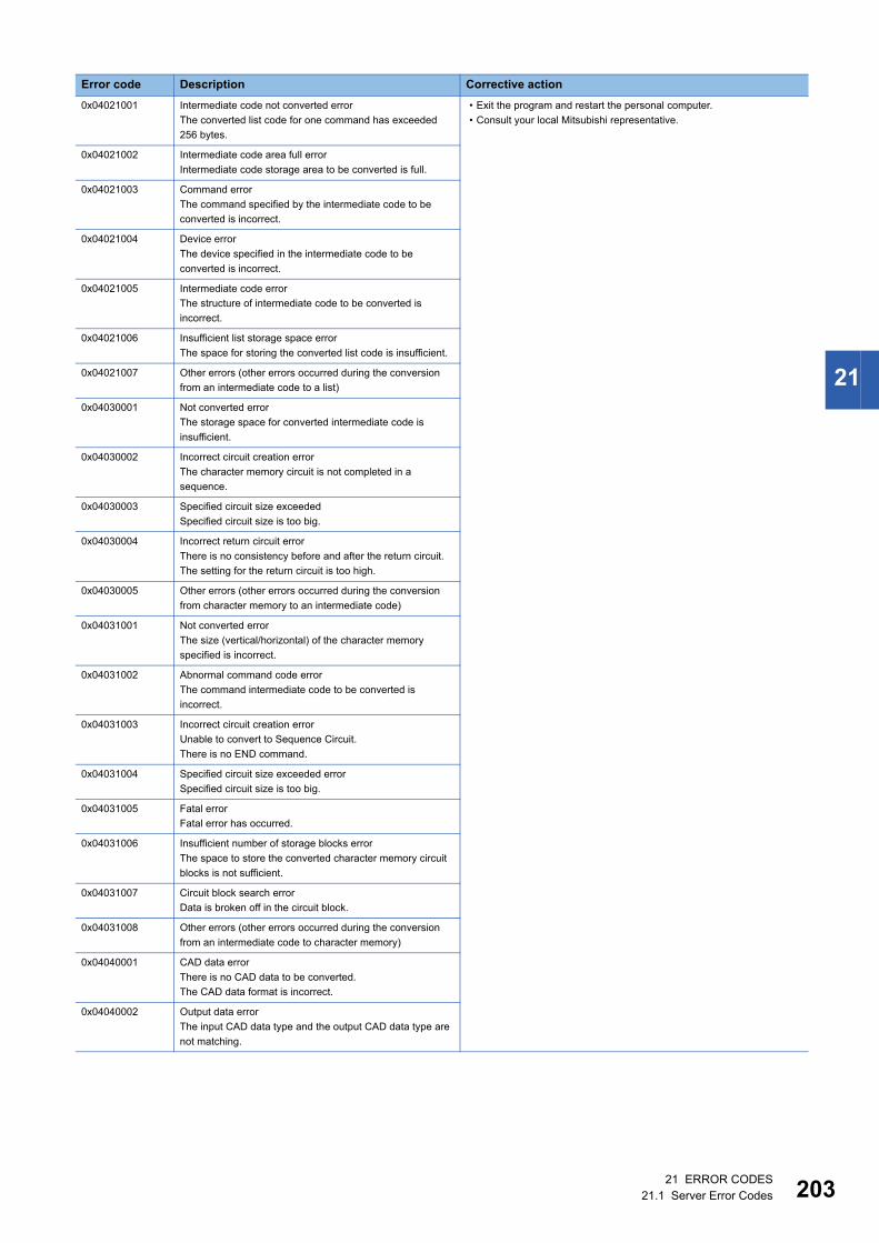
21 ERROR CODES21.1 Server Error Codes 203
21
0x04021001 Intermediate code not converted error
The converted list code for one command has exceeded
256 bytes.
• Exit the program and restart the personal computer.
• Consult your local Mitsubishi representative.
0x04021002 Intermediate code area full error
Intermediate code storage area to be converted is full.
0x04021003 Command error
The command specified by the intermediate code to be
converted is incorrect.
0x04021004 Device error
The device specified in the intermediate code to be
converted is incorrect.
0x04021005 Intermediate code error
The structure of intermediate code to be converted is
incorrect.
0x04021006 Insufficient list storage space error
The space for storing the converted list code is insufficient.
0x04021007 Other errors (other errors occurred during the conversion
from an intermediate code to a list)
0x04030001 Not converted error
The storage space for converted intermediate code is
insufficient.
0x04030002 Incorrect circuit creation error
The character memory circuit is not completed in a
sequence.
0x04030003 Specified circuit size exceeded
Specified circuit size is too big.
0x04030004 Incorrect return circuit error
There is no consistency before and after the return circuit.
The setting for the return circuit is too high.
0x04030005 Other errors (other errors occurred during the conversion
from character memory to an intermediate code)
0x04031001 Not converted error
The size (vertical/horizontal) of the character memory
specified is incorrect.
0x04031002 Abnormal command code error
The command intermediate code to be converted is
incorrect.
0x04031003 Incorrect circuit creation error
Unable to convert to Sequence Circuit.
There is no END command.
0x04031004 Specified circuit size exceeded error
Specified circuit size is too big.
0x04031005 Fatal error
Fatal error has occurred.
0x04031006 Insufficient number of storage blocks error
The space to store the converted character memory circuit
blocks is not sufficient.
0x04031007 Circuit block search error
Data is broken off in the circuit block.
0x04031008 Other errors (other errors occurred during the conversion
from an intermediate code to character memory)
0x04040001 CAD data error
There is no CAD data to be converted.
The CAD data format is incorrect.
0x04040002 Output data error
The input CAD data type and the output CAD data type are
not matching.
Error code Description Corrective action
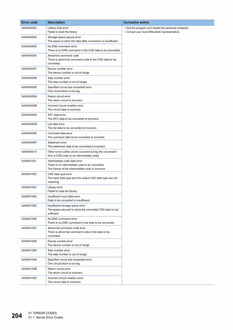
20421 ERROR CODES21.1 Server Error Codes
0x04040003 Library load error
Failed to load the library.
• Exit the program and restart the personal computer.
• Consult your local Mitsubishi representative.
0x04040004 Storage space secure error
The space to store the data after conversion is insufficient.
0x04040005 No END command error
There is no END command in the CAD data to be converted.
0x04040006 Abnormal command code
There is abnormal command code in the CAD data to be
converted.
0x04040007 Device number error
The device number is out of range.
0x04040008 Step number error
The step number is out of range.
0x04040009 Specified circuit size exceeded error
One circuit block is too big.
0x0404000A Return circuit error
The return circuit is incorrect.
0x0404000B Incorrect circuit creation error
The circuit data is incorrect.
0x0404000C SFC data error
The SFC data to be converted is incorrect.
0x0404000D List data error
The list data to be converted is incorrect.
0x0404000E Comment data error
The comment data to be converted is incorrect.
0x0404000F Statement error
The statement data to be converted is incorrect.
0x04040010 Other errors (other errors occurred during the conversion
from a CAD code to an intermediate code)
0x04041001 Intermediate code data error
There is no intermediate code to be converted.
The format of the intermediate code is incorrect.
0x04041002 CAD data type error
The input data type and the output CAD data type are not
matching.
0x04041003 Library error
Failed to load the library.
0x04041004 Insufficient input data error
Data to be converted is insufficient.
0x04041005 Insufficient storage space error
The space secured to store the converted CAD data is not
sufficient.
0x04041006 No END command error
There is no END command in the data to be converted.
0x04041007 Abnormal command code error
There is abnormal command code in the data to be
converted.
0x04041008 Device number error
The device number is out of range.
0x04041009 Step number error
The step number is out of range.
0x0404100A Specified circuit size exceeded error
One circuit block is too big.
0x0404100B Return circuit error
The return circuit is incorrect.
0x0404100C Incorrect circuit creation error
The circuit data is incorrect.
Error code Description Corrective action
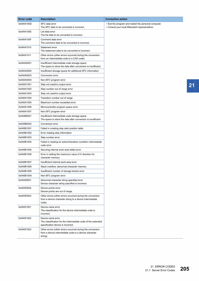
21 ERROR CODES21.1 Server Error Codes 205
21
0x0404100D SFC data error
The SFC data to be converted is incorrect.
• Exit the program and restart the personal computer.
• Consult your local Mitsubishi representative.
0x0404100E List data error
The list data to be converted is incorrect.
0x0404100F Comment data error
The comment data to be converted is incorrect.
0x04041010 Statement error
The statement data to be converted is incorrect.
0x04041011 Other errors (other errors occurred during the conversion
from an intermediate code to a CAD code)
0x040A0001 Insufficient intermediate code storage space
The space to store the data after conversion is insufficient.
0x040A0002 Insufficient storage space for additional SFC information
0x040A0003 Conversion error
0x040A0004 Non-SFC program error
0x040A1001 Step not used/no output error
0x040A1002 Step number out of range error
0x040A1003 Step not used/no output error
0x040A1004 Transition number out of range
0x040A1005 Maximum number exceeded error
0x040A1006 Microcontroller program space error
0x040A1007 Non-SFC program error
0x040B0001 Insufficient intermediate code storage space
The space to store the data after conversion is insufficient.
0x040B0002 Conversion error
0x040B1001 Failed in creating step start position table
0x040B1002 Error reading step information
0x040B1003 Step number error
0x040B1004 Failed in reading an action/transition condition intermediate
code error
0x040B1005 Securing internal work area failed error
0x040B1006 Error in setting the maximum value of X direction for
character memory
0x040B1007 Insufficient internal work area error
0x040B1008 Stack overflow, abnormal character memory
0x040B1009 Insufficient number of storage blocks error
0x040B100A Non-SFC program error
0x04050001 Abnormal character string specified error
Device character string specified is incorrect.
0x04050002 Device points error
Device points are out of range.
0x04050003 Other errors (other errors occurred during the conversion
from a device character string to a device intermediate
code)
0x04051001 Device name error
The classification for the device intermediate code is
incorrect.
0x04051002 Device name error
The classification for the intermediate code of the extended
specification device is incorrect.
0x04051003 Other errors (other errors occurred during the conversion
from a device intermediate code to a device character
string)
Error code Description Corrective action

20621 ERROR CODES21.1 Server Error Codes
0x04052001 Abnormal character string specified error
Device character string specified is incorrect.
• Exit the program and restart the personal computer.
• Consult your local Mitsubishi representative.
0x04052002 Device points error
Device points are out of range.
0x04052003 Other errors (other errors occurred during the conversion
from a device character string to a device representation
code)
0x04053001 Device representation error
The classification specified for the device intermediate code
is incorrect.
0x04053002 Device representation error
The classification for the intermediate code of the extended
specification device is incorrect.
0x04053003 Device representation error
The rectification part specified for the device is incorrect.
0x04053004 Device representation error
The rectification part specified for the extended device is
incorrect.
0x04053005 Other errors (other errors occurred during the conversion
from a device representation code to a device character
string)
0x04064001 Abnormal device intermediate code error
The intermediate code for the device is incorrect.
0x04064002 Other errors (other errors occurred during the conversion
from a device intermediate code to a device name)
0x04065001 Abnormal device name error
The classification for the device intermediate code is
incorrect.
0x04065002 Abnormal device name error
The classification for the intermediate code of the extended
specification device is incorrect.
0x04065003 Other errors (other errors occurred during the conversion
from a device name to an intermediate code)
0x04066001 Device intermediate code error
The intermediate code for the device is incorrect.
0x04066002 Other errors (other errors occurred during the conversion
from a device intermediate code to a device representation)
0x04067001 Device representation error
The classification for the device intermediate code is
incorrect.
0x04067002 Device representation error
The classification for the intermediate code of the extended
specification device is incorrect.
0x04067003 Device representation error
The rectification part specified for the device is incorrect.
0x04067004 Device representation error
The rectification part specified for the extended device is
incorrect.
0x04067005 Other errors (other errors occurred during the conversion
from a device representation to a device intermediate code)
0x04070001 Common data conversion error
The input data of the device comment conversion is
incorrect.
0x04070002 Insufficient common data
The data to be converted is insufficient.
0x04070003 Insufficient storage area
The area where the conversion data is stored is insufficient.
Error code Description Corrective action
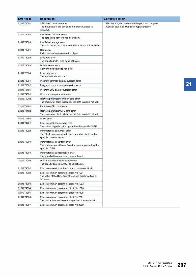
21 ERROR CODES21.1 Server Error Codes 207
21
0x04071001 CPU data conversion error
The input data of the device comment conversion is
incorrect.
• Exit the program and restart the personal computer.
• Consult your local Mitsubishi representative.
0x04071002 Insufficient CPU data error
The data to be converted is insufficient.
0x04071003 Insufficient storage area
The area where the conversion data is stored is insufficient.
0x04072001 Open error
Failed in creating a conversion object.
0x04072002 CPU type error
The specified CPU type does not exist.
0x04072003 Not converted error
Converted object does not exist.
0x04072004 Input data error
The input data is incorrect.
0x04073001 Program common data conversion error
0x04073002 Program common data conversion error
0x04073101 Program CPU data conversion error
0x04074001 Common data parameter error
0x04074002 Network parameter common data error
The parameter block exists, but the data inside is not set.
0x04074101 Parameter CPU data error
0x04074102 Network parameter CPU data error
The parameter block exists, but the data inside is not set.
0x04074103 Offset error
0x04074201 Error in specifying network type
The network type is not supported by the specified CPU.
0x04074202 Parameter block number error
The Block corresponding to the parameter block number
specified does not exist.
0x04074203 Parameter block content error
The contents are different from the ones supported by the
specified CPU.
0x04074204 Parameter block information error
The specified block number does not exist.
0x04074205 Default parameter block is abnormal
The specified block number does not exist.
0x04074301 Error in conversion of the common parameter block
0x04074302 Error in common parameter block No.1001
The value of the RUN-PAUSE settings existence flag is
incorrect.
0x04074303 Error in common parameter block No.1003
0x04074304 Error in common parameter block No.1008
0x04074305 Error in common parameter block No.1100
0x04074306 Error in common parameter block No.2001
The device intermediate code specified does not exist.
0x04074307 Error in common parameter block No.3000
Error code Description Corrective action

20821 ERROR CODES21.1 Server Error Codes
0x04074308 Error in common parameter block No.3002 • Exit the program and restart the personal computer.
• Consult your local Mitsubishi representative.0x04074309 Error in common parameter block No.3004
The settings for the annunciator display mode is incorrect.
0x0407430A Error in common parameter block No.4000
I/O assignment data is not created.
0x0407430B Error in common parameter block No.5000
The specified network is not supported.
0x0407430C Error in common parameter block No.5001
Valid module number is not set while accessing another
station.
0x0407430D Error in common parameter block No.5002
0x0407430E Error in common parameter block No.5003
0x0407430F Error in common parameter block No.5NM0
0x04074310 Error in common parameter block No.5NM1
0x04074311 Error in common parameter block No.5NM2
0x04074312 Error in common parameter block No.5NM3
0x04074313 Error in common parameter block No.6000
0x04074314 Error in common parameter block No.FF18
Link parameter capacity is not set.
0x04074315 Error in common parameter block No.FF25
Calculation circuit check is not set.
0x04074316 Error in common parameter block No.FF30
Sampling trace data is not created.
0x04074317 Error in common parameter block No.FF31
Status latch data is not created.
0x04074318 Error in common parameter block No.FF42
Timer processing points are not set.
0x04074319 Error in common parameter block No.FF30
Setting value device for specified extended timer does not
exist.
0x0407431A Error in common parameter block No.FF44
0x0407431B Error in common parameter block No.FF45
0x0407431C Error in common parameter block No.FF60
Terminal settings are not set.
0x0407431D Error in common parameter block No.FF70
User Release area is not set.
Error code Description Corrective action
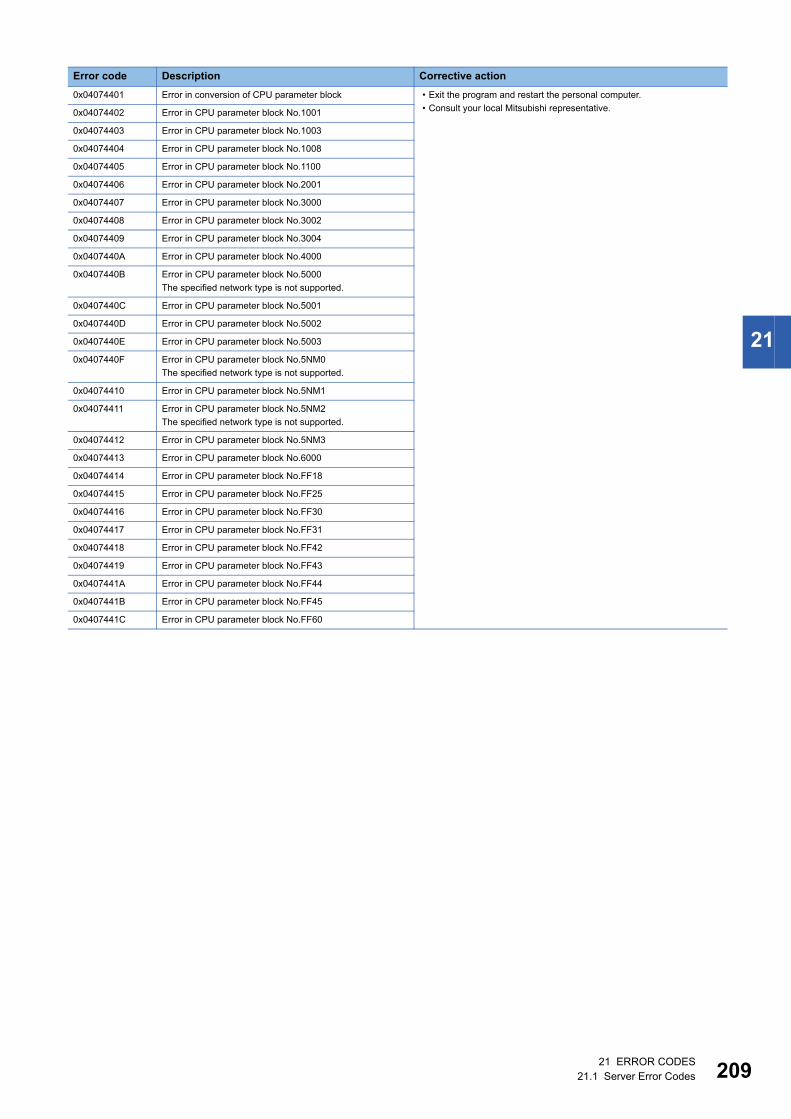
21 ERROR CODES21.1 Server Error Codes 209
21
0x04074401 Error in conversion of CPU parameter block • Exit the program and restart the personal computer.
• Consult your local Mitsubishi representative.0x04074402 Error in CPU parameter block No.1001
0x04074403 Error in CPU parameter block No.1003
0x04074404 Error in CPU parameter block No.1008
0x04074405 Error in CPU parameter block No.1100
0x04074406 Error in CPU parameter block No.2001
0x04074407 Error in CPU parameter block No.3000
0x04074408 Error in CPU parameter block No.3002
0x04074409 Error in CPU parameter block No.3004
0x0407440A Error in CPU parameter block No.4000
0x0407440B Error in CPU parameter block No.5000
The specified network type is not supported.
0x0407440C Error in CPU parameter block No.5001
0x0407440D Error in CPU parameter block No.5002
0x0407440E Error in CPU parameter block No.5003
0x0407440F Error in CPU parameter block No.5NM0
The specified network type is not supported.
0x04074410 Error in CPU parameter block No.5NM1
0x04074411 Error in CPU parameter block No.5NM2
The specified network type is not supported.
0x04074412 Error in CPU parameter block No.5NM3
0x04074413 Error in CPU parameter block No.6000
0x04074414 Error in CPU parameter block No.FF18
0x04074415 Error in CPU parameter block No.FF25
0x04074416 Error in CPU parameter block No.FF30
0x04074417 Error in CPU parameter block No.FF31
0x04074418 Error in CPU parameter block No.FF42
0x04074419 Error in CPU parameter block No.FF43
0x0407441A Error in CPU parameter block No.FF44
0x0407441B Error in CPU parameter block No.FF45
0x0407441C Error in CPU parameter block No.FF60
Error code Description Corrective action

21021 ERROR CODES21.1 Server Error Codes
0x0407441D Error in CPU parameter block No.FF70 • Exit the program and restart the personal computer.
• Consult your local Mitsubishi representative.0x04075001 Common data conversion error
Failed while converting the settings portion of device
memory.
0x04075002 Common data conversion error
Failed while converting the data portion of device memory.
0x04075003 Common data conversion error
Device memory data portion did not exist.
0x04075101 CPU data conversion error
Failed while converting the settings portion of device
memory.
0x04075102 CPU data conversion error
Failed while converting the data portion of device memory.
0x04076001 Common data conversion error
Failed while converting the settings portion of the device
comments.
0x04076002 Common data conversion error
Failed while converting the data portion of device
comments.
0x04076101 CPU data conversion error
Failed while converting the settings portion of the device
comments.
0x04076102 CPU data conversion error
Failed while converting the data portion of device
comments.
0x04077001 Common data conversion error
Failed during the conversion of sampling trace settings
portion.
0x04077002 Common data conversion error
Failed during the conversion of sampling trace data portion.
0x04077101 CPU data conversion error
Failed during the conversion of sampling trace settings
portion.
0x04077102 CPU data conversion error
Failed during the conversion of sampling trace data portion.
0x04078001 Common data conversion error
Failed in the conversion of the status latch settings portion.
0x04078002 Common data conversion error
Failed in the conversion of the status latch data portion.
0x04078101 CPU data conversion error
Failed in the conversion of the status latch settings portion.
0x04078102 CPU data conversion error
Failed in the conversion of the status latch data portion.
0x04079101 Failure history CPU data conversion error
0x0407A101 File list CPU data conversion error
0x0407B101 Error information CPU data conversion error
0x0407C001 Error in conversion of indirect address to device name
Device name storage area is not secured.
Error code Description Corrective action
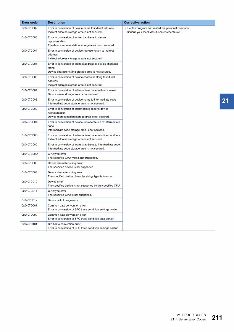
21 ERROR CODES21.1 Server Error Codes 211
21
0x0407C002 Error in conversion of device name to indirect address
Indirect address storage area is not secured.
• Exit the program and restart the personal computer.
• Consult your local Mitsubishi representative.
0x0407C003 Error in conversion of indirect address to device
representation
The device representation storage area is not secured.
0x0407C004 Error in conversion of device representation to indirect
address
Indirect address storage area is not secured.
0x0407C005 Error in conversion of indirect address to device character
string
Device character string storage area is not secured.
0x0407C006 Error in conversion of device character string to indirect
address
Indirect address storage area is not secured.
0x0407C007 Error in conversion of intermediate code to device name
Device name storage area is not secured.
0x0407C008 Error in conversion of device name to intermediate code
Intermediate code storage area is not secured.
0x0407C009 Error in conversion of intermediate code to device
representation
Device representation storage area is not secured.
0x0407C00A Error in conversion of device representation to intermediate
code
Intermediate code storage area is not secured.
0x0407C00B Error in conversion of intermediate code to indirect address
Indirect address storage area is not secured.
0x0407C00C Error in conversion of indirect address to intermediate code
Intermediate code storage area is not secured.
0x0407C00D CPU type error
The specified CPU type is not supported.
0x0407C00E Device character string error
The specified device is not supported.
0x0407C00F Device character string error
The specified device character string, type is incorrect.
0x0407C010 Device error
The specified device is not supported by the specified CPU.
0x0407C011 CPU type error
The specified CPU is not supported.
0x0407C012 Device out of range error
0x0407D001 Common data conversion error
Error in conversion of SFC trace condition settings portion
0x0407D002 Common data conversion error
Error in conversion of SFC trace condition data portion
0x0407D101 CPU data conversion error
Error in conversion of SFC trace condition settings portion
Error code Description Corrective action
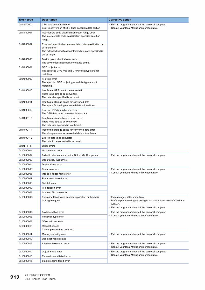
21221 ERROR CODES21.1 Server Error Codes
0x0407D102 CPU data conversion error
Error in conversion of SFC trace condition data portion
• Exit the program and restart the personal computer.
• Consult your local Mitsubishi representative.
0x04080001 Intermediate code classification out of range error
The intermediate code classification specified is out of
range.
0x04080002 Extended specification intermediate code classification out
of range error
The extended specification intermediate code specified is
out of range.
0x04080003 Device points check absent error
The device does not check the device points.
0x04090001 GPP project error
The specified CPU type and GPP project type are not
matching.
0x04090002 File type error
The specified GPP project type and file type are not
matching.
0x04090010 Insufficient GPP data to be converted
There is no data to be converted.
The data size specified is incorrect.
0x04090011 Insufficient storage space for converted data
The space for storing converted data is insufficient.
0x04090012 Error in GPP data to be converted
The GPP data to be converted is incorrect.
0x04090110 Insufficient data to be converted error
There is no data to be converted.
The data size specified is insufficient.
0x04090111 Insufficient storage space for converted data error
The storage space for converted data is insufficient.
0x04090112 Error in data to be converted
The data to be converted is incorrect.
0x04FFFFFF Other errors
0x10000001 No command error
0x10000002 Failed to start communication DLL of MX Component. • Exit the program and restart the personal computer.
0x10000003 Open failed. (DiskDrive)
0x10000004 Duplex Open error
0x10000005 File access error • Exit the program and restart the personal computer.
• Consult your local Mitsubishi representative.0x10000006 Incorrect folder name error
0x10000007 File access denied error
0x10000008 Disk full error
0x10000009 File deletion error
0x1000000A Incorrect file name error
0x1000000C Execution failed since another application or thread is
making a request.
• Execute again after some time.
• Perform programming according to the multithread rules of COM and
ActiveX.
• Exit the program and restart the personal computer.
0x1000000D Folder creation error • Exit the program and restart the personal computer.
• Consult your local Mitsubishi representative.0x1000000E Folder/file type error
0x1000000F Offset address error
0x10000010 Request cancel
Cancel process has occurred.
0x10000011 Memory securing error • Exit the program and restart the personal computer.
0x10000012 Open not yet executed
0x10000013 Attach not executed error • Exit the program and restart the personal computer.
• Consult your local Mitsubishi representative.
0x10000014 Object invalid error • Exit the program and restart the personal computer.
• Consult your local Mitsubishi representative.0x10000015 Request cancel failed error
0x10000016 Status reading failed error
Error code Description Corrective action
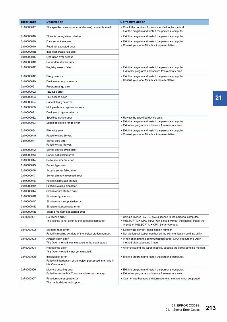
21 ERROR CODES21.1 Server Error Codes 213
21
0x10000017 The specified size (number of devices) is unauthorized. • Check the number of points specified in the method.
• Exit the program and restart the personal computer.
0x10000018 There is no registered device. • Exit the program and restart the personal computer.
0x10000019 Data set not executed • Exit the program and restart the personal computer.
• Consult your local Mitsubishi representative.0x1000001A Read not executed error
0x1000001B Incorrect create flag error
0x1000001C Operation over access
0x1000001D Redundant device error
0x1000001E Registry search failed. • Exit the program and restart the personal computer.
• Exit other programs and secure free memory area.
0x1000001F File type error • Exit the program and restart the personal computer.
• Consult your local Mitsubishi representative.0x10000020 Device memory type error
0x10000021 Program range error
0x10000022 TEL type error
0x10000023 TEL access error
0x10000024 Cancel flag type error
0x10000030 Multiple device registration error
0x10000031 Device not registered error
0x10000032 Specified device error • Review the specified device data.
• Exit the program and restart the personal computer.
• Exit other programs and secure free memory area.0x10000033 Specified device range error
0x10000034 File write error • Exit the program and restart the personal computer.
• Consult your local Mitsubishi representative.0x10000040 Failed to start Server.
0x10000041 Server stop error
Failed to stop Server.
0x10000042 Server started twice error
0x10000043 Server not started error
0x10000044 Resource timeout error
0x10000045 Server type error
0x10000046 Access server failed error
0x10000047 Server already accessed error
0x10000048 Failed in simulator startup
0x10000049 Failed in exiting simulator
0x1000004A Simulator not started error
0x1000004B Simulator type error
0x1000004C Simulator not supported error
0x1000004D Simulator started twice error
0x1000004E Shared memory not started error
0xF0000001 No-license error
The license is not given to the personal computer.
• Using a license key FD, give a license to the personal computer.
• MELSOFT MX OPC Server UA is used without the license. Install the
license of MELSOFT MX OPC Server UA duly.
0xF0000002 Set data read error
Failed in reading set data of the logical station number.
• Specify the correct logical station number.
• Set the logical station number on the communication settings utility.
0xF0000003 Already open error
The Open method was executed in the open status.
• When changing the communication target CPU, execute the Open
method after executing Close.
0xF0000004 Not opened error
The Open method is not yet executed.
• After executing the Open method, execute the corresponding method.
0xF0000005 Initialization error
Failed in initialization of the object possessed internally in
MX Component.
• Exit the program and restart the personal computer.
0xF0000006 Memory securing error
Failed to secure MX Component internal memory.
• Exit the program and restart the personal computer.
• Exit other programs and secure free memory area.
0xF0000007 Function non-support error
The method does not support.
• Can not use because the corresponding method is not supported.
Error code Description Corrective action

21421 ERROR CODES21.1 Server Error Codes
0xF1000001 Character code conversion error
Failed to convert character code (UNICODE to ASCII code,
or ASCII code to UNICODE).
• Check the character string specified in the method.
• The ASCII character string acquired from the programmable controller
CPU is abnormal.
• Review the system, e.g. programmable controller CPU, module setting,
and cable status.
• Exit the program and restart the personal computer.
• Retry the GetCpuType method.
0xF1000002 Start I/O number error
The specified start I/O number is incorrect.
A matching start I/O number does not exist.
• Check the value of the start I/O number specified in the method.
• Using the GPP function, check the programmable controller parameters
(I/O assignment).
0xF1000003 Buffer address error
The specified buffer address is incorrect.
The buffer address is outside the range.
• Check the value of the buffer address specified in the method.
0xF1000004 Buffer read size error
As a result of buffer read, the specified size could not be
acquired.
• Execute Open again.
• Review the system, e.g. programmable controller CPU, module setting,
and cable status.
• Retry.
• Exit the program.
0xF1000005 Size error
The size specified in the read/write method is abnormal.
The read/write first number plus size exceeds the device or
buffer area.
• Check the size specified in the method.
0xF1000006 Operation error
The operation specified for remote operation is an abnormal
value.
• Check the operation specifying value specified in the method.
0xF1000007 Clock data error
The clock data is abnormal.
• Check the clock data specified in the method.
• Set the correct clock data to the clock data of the programmable
controller CPU.
0xF1000008 Monitored device registration count excess
0 or less device point was registered in the
EntryDeviceStatus method.
20 or more device points ware registered in the
EntryDeviceStatus method.
• Register device points between 1 and 20 in the EntryDeviceStatus
method.
0xF1000009 Monitored device data registration error • After cancelling the registration in the FreeDeviceStatus method,
execute the EntryDeviceStatus method again.
0xF1000010 Failed to start device status monitor processing.
Failed to end device status monitor processing
• Start/end the device status monitor processing again in the
EntryDeviceStatus method.
0xF1000011 The VARIANT argument data type is wrong. • Review the data type specified for the VARIANT argument.
• Check whether the array variable size is large enough.
• Check whether the data type specified in the corresponding method has
been set.
0xF1000012 The device status monitoring interval is set outside the
range from 1 second to 1 hour (1 to 3600).
• Specify the device status monitoring time between 1 and 3600.
0xF1000013 Already connected error
After Connect was executed, it was executed again in the
same object.
• Execute the Connect method after executing the Disconnect method.
0xF1000015 Exclusive control failed error
Failed in exclusive control process while executing the
Connect and Disconnect.
• When Connect or Disconnect is being executed for any other object,
execute the failed method (Connect/Disconnect) again after the
completion of the Connect/Disconnect method.
• If the Connect/Disconnect process is in progress only for the self object,
perform the following.
• Exit the program.
• Restart the personal computer.
0xF1000019 Not closed error
Disconnect was executed while in Open state.
• Try Disconnect again after executing Close.
0xF100001D Not connected error
Open was executed before executing Connect, or
Disconnect was executed.
• Execute Connect once, and execute Open again.
• Try Disconnect again after executing Connect.
0xF100001E Fatal error • Exit the program.
• Restart the personal computer.
• Consult your local Mitsubishi representative.
0xF2000003 Invalid data was received.
Causes can be the following.
• Incorrect data packet received due to noise.
• Retry.
• Check the communication device used at the other end.
Error code Description Corrective action

21 ERROR CODES21.1 Server Error Codes 215
21
*1 For the method for increasing the minimum working set size of the personal computer, refer to the following manual.MELSEC Data Link Library Reference Manual
0xF200000B Timeout reached for the call back receive waiting time. • Increase the call back receive waiting time
(ActCallbackReceptionWaitingTimeOut) and execute Connect again.
0xF200000C The password of QJ71C24/CMO module could not be
resolved.
• Set a password to ActPassword property, and then execute the failed
method again.
Error code Description Corrective action

21621 ERROR CODES21.1 Server Error Codes
Error codes in a connection destination deviceThe following explains the error codes returned from a module or a network board connected to Server.
When an error is detected by the module or network board, any of the error code shown in the following table is returned.
The upper two bytes indicates the module where an error is detected, and the lower two bytes indicates an error code which
is returned from the module where an error occurred.
For details on errors, refer to the manual of a module or network board which is indicated in the error code.
Precautions
The following shows the considerations for checking error codes returned by CPUs, modules, and network boards.
■Property setting errorIf the actual system configuration and the set property values do not match, the upper two bytes does not indicate an error-
detected module.
For example, if FXCPU property value is set to ActCpuType when using QCPU, the upper two bytes may indicate that FXCPU
has detected an error.
In this case, verify the actual system configuration and all property values, and establish the communication again.
Additionally, when using ActUtlType control, check the setting contents of the communication settings utility.
■When accessing another stationWhen accessing another station, the error code of a relay module (CC-Link IE Controller Network, MELSECNET/H, CC-Link,
serial communication, or Ethernet module) may be stored to the lower two bytes.
In this case, there is a possibility that the upper two bytes that indicates an error-detected module does not match the module
where an error has occurred. Check the system configuration, and then refer to the manual of the CPU, relay network module,
and network board used.
Error code Module in which an error occurred
0x01010000 to 0x0101FFFF Motion controller CPU
0x01070000 to 0x0107FFFF CC-Link IE Controller Network board, MELSECNET/H board, CC-Link Ver.2 board
0x01090000 to 0x0109FFFF FXCPU
0x010A0000 to 0x010AFFFF QCPU, QSCPU, RCPU, FX5CPU
0x010B0000 to 0x010BFFFF Q series-compatible C24
0x010C0000 to 0x010CFFFF Q series-compatible E71
0x010D0000 to 0x010DFFFF Personal computer CPU module
0x010F0000 to 0x010FFFFF GOT
APPXAppendix 1 Additions and Changes from Previous Version 217
A
APPENDIXAppendix 1 Additions and Changes from Previous
VersionThis section shows the additions and changes with upgrade.
Version 3.01B
Item Description Reference
Module The following modules are supported.
• R00CPU, R01CPU, R02CPU, R08PSFCPU, R16PSFCPU, R32PSFCPU,
R120PSFCPU
Page 15 Supported modules

218APPXAppendix 2 Version Compatibility
Appendix 2 Version CompatibilityThis section explains the considerations when using Configuration Tool, MX OPC UA Server, and a configuration file with
different versions.
Using a configuration file created in Configuration Tool version 2.04 or earlier
■When using it in MX OPC UA Server version 3.0.0 or later
■When using it in Configuration Tool version 3.00A or later
Using a configuration file created in Configuration Tool version 3.00A or later
■When using it in MX OPC UA Server version 2.0.4 or earlier
■When using it in Configuration Tool version 2.04 or earlier
Using a configuration file created in Configuration Tool version 3.01B or later
■When using it in Configuration Tool version older than one in which the file was created (excluding version 2.04 or earlier)
Operation Consideration
Server startup MX OPC UA Server cannot start because cfg file is not supported.
Operation Consideration
Save (offline) A message to confirm a file name appears because the extension of the configuration file is changed.
Save (online) A cfg file is deleted, and new cfg3 file with the same name is created.
Operation Consideration
Server startup MX OPC UA Server cannot start because cfg3 file is not supported.
Operation Consideration
Open a file A file cannot open because cfg3 file is not supported.
Open Server A file cannot open because cfg3 file is not supported.
Save (offline) A file cannot be saved because cfg3 file is not supported.
Save (online) A file cannot be saved because cfg3 file is not supported.
Operation Consideration
Open a file Data that cannot be used in Configuration Tool may not be displayed properly.
To display data in Configuration Tool properly, the latest Configuration Tool is required to be installed.Open Server

APPXAppendix 2 Version Compatibility 219
A
The versions of MX OPC UA Server and Configuration Tool are different
■When connecting MX OPC UA Server version 2.0.4 or earlier and Configuration Tool version 3.00A or later
■When connecting MX OPC UA Server version 3.0.0 or later and Configuration Tool version 2.04 or earlier
■When connecting MX OPC UA Server version 3.0.0 or later and Configuration Tool version 3.00A or later
Operation Consideration
Save settings to Server The settings cannot be saved because cfg3 file is not supported by Server.
Save settings with the property screen
(online)
The settings cannot be saved because the version of the setting information in the memory and the version of the
sever do not match.
Operation Consideration
Save settings to Server The settings cannot be saved to a file because the version of the setting information in Sever and Configuration
Tool do not match.
Save settings with the property screen
(online)
The settings cannot be saved because the version of the setting information in the memory and the version of the
sever do not match.
Operation Consideration
Save If the version of Server is older than that of Configuration Tool, a configuration file cannot be saved.
Install the latest Server or use Configuration Tool with the same version as Server.
Save settings with the property screen
(online)
If the version of the setting information in the memory and the version of Server do not match, the settings cannot
be saved.
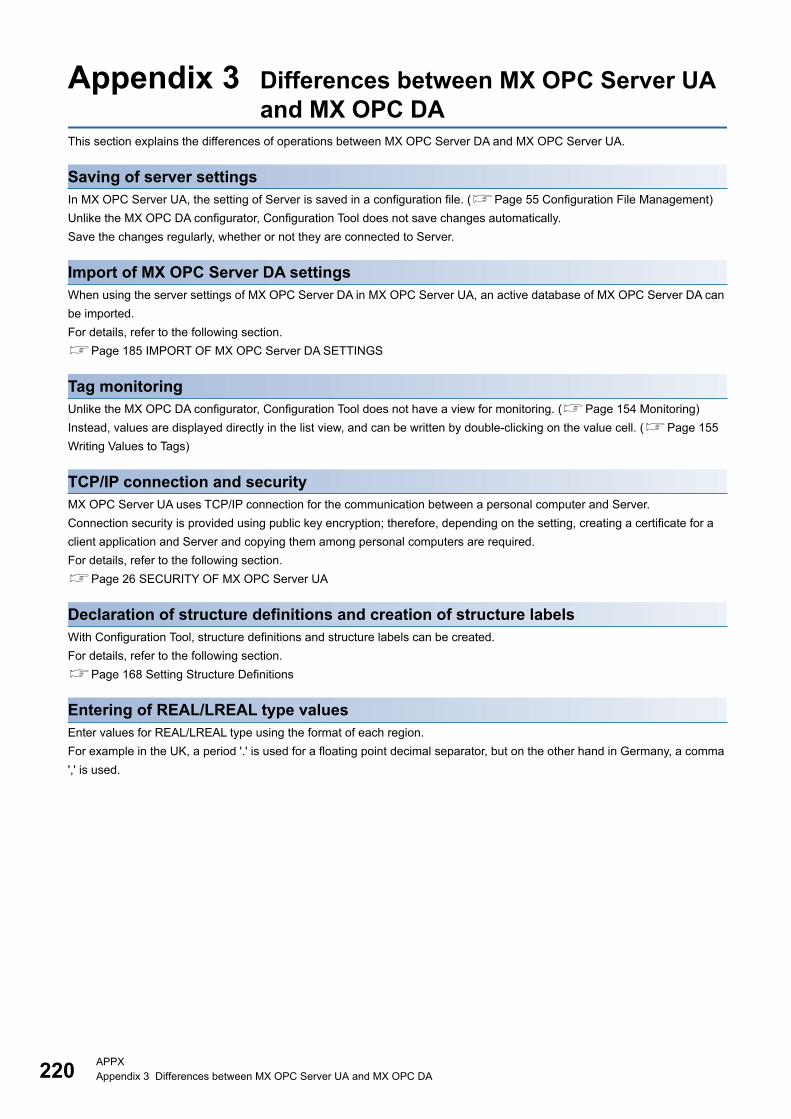
220APPXAppendix 3 Differences between MX OPC Server UA and MX OPC DA
Appendix 3 Differences between MX OPC Server UA and MX OPC DA
This section explains the differences of operations between MX OPC Server DA and MX OPC Server UA.
Saving of server settingsIn MX OPC Server UA, the setting of Server is saved in a configuration file. (Page 55 Configuration File Management)
Unlike the MX OPC DA configurator, Configuration Tool does not save changes automatically.
Save the changes regularly, whether or not they are connected to Server.
Import of MX OPC Server DA settingsWhen using the server settings of MX OPC Server DA in MX OPC Server UA, an active database of MX OPC Server DA can
be imported.
For details, refer to the following section.
Page 185 IMPORT OF MX OPC Server DA SETTINGS
Tag monitoringUnlike the MX OPC DA configurator, Configuration Tool does not have a view for monitoring. (Page 154 Monitoring)
Instead, values are displayed directly in the list view, and can be written by double-clicking on the value cell. (Page 155
Writing Values to Tags)
TCP/IP connection and securityMX OPC Server UA uses TCP/IP connection for the communication between a personal computer and Server.
Connection security is provided using public key encryption; therefore, depending on the setting, creating a certificate for a
client application and Server and copying them among personal computers are required.
For details, refer to the following section.
Page 26 SECURITY OF MX OPC Server UA
Declaration of structure definitions and creation of structure labelsWith Configuration Tool, structure definitions and structure labels can be created.
For details, refer to the following section.
Page 168 Setting Structure Definitions
Entering of REAL/LREAL type valuesEnter values for REAL/LREAL type using the format of each region.
For example in the UK, a period '.' is used for a floating point decimal separator, but on the other hand in Germany, a comma
',' is used.

APPXAppendix 4 Restart of Service 221
A
Appendix 4 Restart of ServiceThis section shows the procedures to restart service in Windows for each operating system.
Windows Server 2003/2008 R2/2012 R2
Operating procedure
1. Windows Server 2008 R2: Click the Windows icon, enter 'Services.msc' in the search box, and press the key.
When the "User Account Control" screen appears, click the [Yes] button.
2. Right-click "MELSOFT MX OPC Server UA" in the list, and click the [Restart] button.
Windows 7
Operating procedure
1. Select the Windows Start, enter 'Services.msc' in the search box, and press the key.
When the "User Account Control" screen appears, click the [Yes] button.
2. Right-click "MELSOFT MX OPC Server UA" in the list, and click the [Restart] button.
Windows 8 or 8.1
Operating procedure
1. Move the mouse pointer on the upper right of the screen to display the Charms bar.
2. Click [Search] in the Charms bar.
3. Enter 'Services.msc' in the search box of the Search charm, and enter the key.
When the "User Account Control" screen appears, click the [Yes] button.
4. Right-click "MELSOFT MX OPC Server UA" in the list, and click the [Restart] button.
Windows 10
Operating procedure
1. Enter 'Services.msc' in the search box, and enter the key.
When the "User Account Control" screen appears, click the [Yes] button.
2. Right-click "MELSOFT MX OPC Server UA" in the list, and click the [Restart] button.
222APPXAppendix 5 USB Driver Installation Procedure
Appendix 5 USB Driver Installation ProcedureTo communicate with a CPU module via USB, installing a USB driver is required.
If multiple MELSOFT products are already installed, refer to the installation location of the first product.
Windows 7 or later
Operating procedure
1. Connect a personal computer and a CPU module with a USB cable, and turn the power of the programmable controller
ON.
2. Select [Control Panel] [System and Security] [Administrative Tools] [Computer Management] [Device
Manager] from Windows Start*1. Right-click "Unknown device" and click "Update Driver Software".
3. Select "Browse my computer for driver software" on the "Update Driver Software" screen, and specify
'Easysocket\USBDrivers' in the folder where MELSOFT MX OPC Server UA Configuration Tool is installed on the next
screen.
*1 On the Start screen or from the Start menu.

223
I
INDEX
F
Function list . . . . . . . . . . . . . . . . . . . . . . . . . 17,19
U
USB driver . . . . . . . . . . . . . . . . . . . . . . . . . . . 222

224
MEMO

225
REVISIONS*The manual number is given on the bottom left of the back cover.
Japanese manual number: SH-081858-B
2017 MITSUBISHI ELECTRIC CORPORATION
Revision date *Manual number Description
October 2017 SH(NA)-081859ENG-A First edition
December 2017 SH(NA)-081859ENG-B ■Added or modified parts
TERMS, Chapter 2, Chapter 8, Section 12.1, Chapter 20, Section 21.1, Appendix 1, Appendix 2
This manual confers no industrial property rights of any other kind, nor does it confer any patent licenses. Mitsubishi Electric Corporation cannot be held
responsible for any problems involving industrial property rights which may occur as a result of using the contents noted in this manual.

226
TRADEMARKSMicrosoft, Windows, and Internet Explorer are either registered trademarks or trademarks of Microsoft Corporation in the
United States and/or other countries.
Ethernet is a registered trademark of Fuji Xerox Co., Ltd. in Japan.
The company names, system names and product names mentioned in this manual are either registered trademarks or
trademarks of their respective companies.
In some cases, trademark symbols such as '' or '' are not specified in this manual.


SH(NA)-081859ENG-B(1712)
MODEL:SW3DND-OPCUAS-O-E
Specifications subject to change without notice.
When exported from Japan, this manual does not require application to theMinistry of Economy, Trade and Industry for service transaction permission.
HEAD OFFICE : TOKYO BUILDING, 2-7-3 MARUNOUCHI, CHIYODA-KU, TOKYO 100-8310, JAPANNAGOYA WORKS : 1-14 , YADA-MINAMI 5-CHOME , HIGASHI-KU, NAGOYA , JAPAN