melting behavior of coal ash materials …web.anl.gov/pcs/acsfuel/preprint...
TRANSCRIPT
MELTING BEHAVIOR OF COAL ASH MATERIALS FROM COAL ASH COMPOSITION
by
Karl S. Vorres Institute of Cas Technology
Chicago, Illinois 606 16
May 1977
INTRODUCTION
The melting behavior of coal ash materials is characterized by several
temperatures relating to stages of deformation of cone-shaped ash samples
on heating. range i s a l so useful for characterization.
primarily for design of steam generation equipment, but m a y be usefully
extended to coal conversion processes such a s gasification. Coal ash does
not mel t sharply like a pure compound, but ra ther softens over a tempera-
ture range a s the temperature is increased.
exhibits a plastic range between the solid and mobile liquid states.
temperature range corresponding to the plastic state, a s well a s viscosity
and melting phemonena. depend on the composition of the ash and the gaseous environment.
of temperatures and gaseous environments have demonstrated this
Viscosity of coal ash melts through the molten temperature
This information has been used
As it melts, the heated ash
The
Studies of the melting and viscosity of ash melts over a range
The purpose of this paper is to p r w i d e some framework f o r understanding
the observed behavior, and to suggest use of a concept that should be helpful
in further studies of that behavior.
Acids and Bases
The melting and viscosity behavior has been described a s a function of
the composition of the coal ash in t e r m s of acids and bases. The acids have been defined as oxides of Al. Si, and Ti, while the bases were oxides of Na,
K. Ca, Mg, and Fe.
118
The structural inorganic chemical characteristics of the acids and bases
will be of interest in establishing the reasons for labels such a s acid or base,
and i n understanding the impact of the acid or base characteristics on the melting or viscosity properties of coal ash.
Inorganic cations m a y be characterized by ionic radii for their common
valences.
weight for a given valence.
ganic cations indicated above a r e fisted below in Angstrom units:
In general, the radii decrease with charge, and a l so with atomic
The radii, according to Ahrens, for the inor-
sit4 0.42
~ 1 ' ~ 0.51
Fe" 0.64
Mg t2 0.67
Ti+4 0.68
Fe" 0.74
N a " 0.94
Ca " 0.99
K +l 1.33
The two values a r e given for i ron because of the importance of both valence
s tate 8 .
In crystals, and in some cases for liquids, the cations a r e surrounded by
a specific number of anions.
the rat io of the radii of the two oppositely charged species. A coordination
number of four produces a tetrahedron and i s expected between radius ratio limits of 0.225 and 0.414.
octahedron and i s expected between radius ra t io limits of 0.414 and 0.732.
The coordination number of eight is expected for somewhat larger radius ratios.
This coordination number is determined by
A coordination number of six produces an
In coal ash the predominant anion is the oxide ion. Using a radius of 0
1.40 A for the oxide and applying the radius ratio cr i ter ia , tetrahedral
coordination is expected for cations with a radius smaller than 0.58 A or
specifically Si" and Alt3.
cations between 0.58 and 1.03 2 or Fet3, Mg", Tit4, Fet2. Na", and t z t Ca . The remaining K would be expected to have a cubic configuration
with coordination number eight.
numbers would be expected in melts.
0
The octahedral configuration is expected for
Under proper conditions, these coordination
119
Ionic Potential
Another useful concept is the ionic potential which i s defined as the quotient of the valence and ionic radius for a given ion.
indicates something about the ability of a cation to coordinate anions about it.
A higher ionic potential indicates the ability of one cation type to compete
effectively with other cations f o r available anions t o form complex ions
such a s SO,-' i n a mixture like coal ash.
tials of the species of interest a re :
This parameter
The values for the ionic poten-
si* 9.52 FeS2 2.70
~ 1 + 3 5.88 , Cat' 2.02
Ti '* 5.88
Fet3 4.69
N a " 1.06
K 0.752
Mg " 2.98
The highest values belong to the acid group S i , Al , and Ti, while the lowest
values belong t o the bases.
It is suggested h e r e that the ionic potential may be the physical charac- teristic which is useful in quantifying acid and base behavior, and would
also be useful in future efforts to correlate melting behavior or viscosity
with chemical composition.
The ionic potential is a measure of a cation's ability to compete for anions
in order to f o r m a complex ion of the form MOin. The abi l i ty is also
dependent on the available oxide ions.
oxide ions would be limited in the pure oxide Si 0, if it were not for the
possibility of sharing oxide ions between different Si.
S i O2 groups in a V shape can f o r m polymer type groupings. could be extremely long chains of linked tetrahedra. possible. If additional oxide ions became
the species needed to terminate the chains.
the groupings would terminate more frequently and have a smaller agglomerate weight.
potential such as the alkalis or alkaline earths. These would be expected to dissociate into hard sphere ions, and the oxide ions would be coordinated by
cations of the highest ionic potential.
The ability of S i t o coordinate four
A s a result, repeating
These groupings
Other forms a r e also
available, then they would provide
A s more oxide became available,
A source for oxide ions would be oxides of cations with low ionic
120
It is suggested that the role of acids in coal ash melts is that of polymer
formers with the greatest tendency to form polymers correlating with the
greatest ionic potential.
The oxide ions would be attracted to the ions of high potential to break up
polymers and reduce viscosity.
The role of bases i s that of oxide ion donors.
In general, the available oxide ions from cations would tend to reduce
the size of polymeric groups associated with cations of high ionic potential.
Additions of compounds increasing the available oxide ion concentration
would decrease the viscosity of a melt rich in si and A1 typical of eastern coal ash material. This effect h a s already been noted.
The Behavior of Iron
The two valence states of i ron give significantly different values with The special importance of the fe r r ic ion being between the two groups.
i ron can, in par t a t least, be correlated with the two valences it displays. This m a y be compared with the amphoteric behavior of certain other species.
On the basis of the table of ionic potentials, the fe r r ic ion m a y be thought of
a s a weak acid, and the ferrous ion as a base. In practice, the iron i n coal ash in boilers will exist a s a mixture of the two states. Only a minor par t ,
frequently about 20%, is Fe,O,.
possibly some elemental iron.
classifying iron oxides (if they must be lumped into one type) with the bases ,
even though they a r e listed as Fe,O,.
The major par t (about 80%) is FeO, with
This indicates the appropriateness of
The gaseous environment i s important in determining properties of coal Studies have shown a marked reduction of viscosity of mel ts ash systems.
in going from oxidizing to reducing conditions, which would significantly
alter the proportion of fe r r ic and ferrous ions. This change in properties
would be consistent with a complex ion forming tendency for the fe r r ic ion with its high ionic potential, and an oxide ion donor role for the ferrous ion
with i ts lower ionic potential.
in a reducing environment: I) reduction of concentration of polymer
forming fe r r ic ions, and 2 ) increase in oxide ion concentration available for cations with high ionic potential. The oxide ions would have been associated
with the ferrous ions.
Two factors would work to reduce the viscosity
121
Conceptual Structural Considerations
Winegartner and Rhodes) indicated that the coefficients in front of the bases
CaO, MgO, K,O, and Na,O should each be one when calculating the softening
temperature using the base-toacid ratio and expressing the a s h composition
for these mater ia ls in The implication of that observation in the context of this paper is that the
bases a r e equally effective a s oxide ion donors.
oxide unit. This is a l so consistent with characterizing FeO a s a base and indicating the
role of oxide ion donor for FeO.
percentages rather than weight percentages.
Each formula contains one They fur ther note that Fe20, should really be expressed a s FeO.
The melting process m a y be pictured a s application of energy to disrupt
the crystal lattice of a solid. The lattice of the solid m a y be modified by
the impurities t o permit easier melting through introduction of additional
large oxide ions in the acid oxide structure.
would probably occur in the available interstices appropriate for the base
coordination number.
thermal requirement for melting or a lower melting point. implication of Winegartner and Rhodes work is that the number of oxide ions is most significant, and that the nature of the base cations is not significant
in affecting the softening temperature.
SUMMARY
Insertion of base cations
The resultant lattice s t ra in would yield a lower
The further
The ionic potential (valence divided by ionic radius) may be used a s a
measure of acids and bases in predicting coal ash melting and viscosity
f rom the chemical composition.
ion former with anions provided by bases which in coal ash systems are oxide ion donors.
trations, polymers tend to form in the melts.
polymer s ize and would decrease viscosity. a l ter the relative concentration of fe r r ic and ferrous ions, interconverting
acid and base ions. In general, bases a r e reported to be equally effective oxide ion donors.
amount of oxide ion provided to the system.
The role of a n acid is that of a complex
In systems containing acids and limited oxide ion concen-
Addition of bases reduces
The gaseous environment m a y
The effects of base addition a r e proportional to the
122
REFERENCES CITED
1. Sage, W. L. and McIlroy, J. B., J. Engineering for Power, g, 145 (1960).
2. Rees, 0. W., Ill. State Geological Survey, Circular 365 (1964).
3. Winegarher. E. C. and Rhodes, J. Engineering for Power, 97, 395 (1975).
123
CHARACTERISTICS OF ASH AGGLOMERATES FROM AN ASH-AGGLOMERATING GASIFIER
David M. Mason
Institute of Gas Technology 3424 S. State Street
Chicago, Illinois 60616
INTRODUCTION
An ash-agglomerating fluidized-bed gasifier has been under investigation a t the Institute of Gas Technology (IGT). In such a process, carbon utilization can be sub- stantially improved over that obtained when ash is removed by continually discharg- ing a nonselective portion of the fluidized bed containing both ash and carbon.
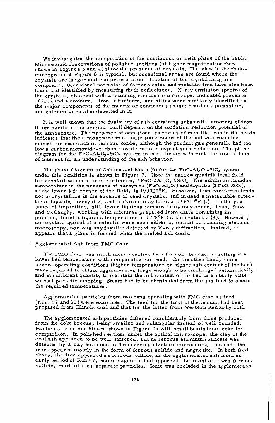
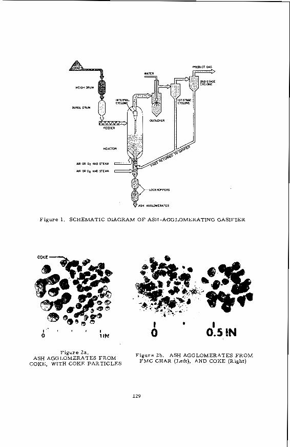
The pilot plant gasifier has a diameter of 4 feet and operates a t near atmospher- ic pressure. leaves the gasifier through a centrally located venturi tube through which par t of the gaseous feed (steam plus air or oxygen) i s introduced to the reactor. the gasifier and i t s operation have been described by Sandstrom. Rehmat. and Bair in a recent paper (8). a s h obtained during gasification of coke breeze and FMC char , and we discuss the probable mechanisms of their formation.
The schematic diagram of Figure 1 shows that agglomerated ash
Details of
In the present paper, we describe the agglomerated
EXPERIMENTAL
Petrographic samples were mounted, sectioned, and polished mostly according to methods employed in coal petrography (1). observations and determination of reflectance has been described (4).
Our apparatus for microscopical
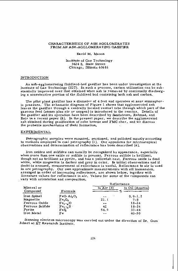
I ron oxides and sulfides can usually be recognized by appearance, especially when m o r e than one oxide or sulfide i s present. Fer rous sulfide is brilliant, though not a s brilliant as pyrite, and has a yellowish cast. Fer rous oxide is dead white, while magnetite is darker and gray in color. In initial observations and if doubt is aroused, measurement of reflectance i s useful. Reflectance in a i r i s used in ore petrography. arranged in order of increasing reflectance, a r e shown below, together with literature values for reflectance in air. Values for some of the compounds can vary with orientation and composition.
O u r own approximate measurements with oil immersion,
Reflect anc e Mineral or Compound Formula
Iron Spinel FeO. A1,0,
Fer rous Oxide Fe, -,O Ferrous Sulfide Fel -,S .
Iron Metal F e
Magnetite Fe304
Pyrite FeS,
In Air (3) In Oil (Approx) %
0. 9-1.2 7-8
18-24 18-24
3 3 - 4 4 40-50
Scanning electron microscopy was carr ied out under the direction of Dr. Oom Johari a t IIT Research Institute.
124
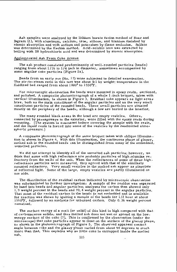
Ash samples were analyzed by the lithium borate fusion method of Boar a n d Ingram (2), with aluminum, calcium, iron, silicon, and titanium finished by atomic absorption and with sodium and potassium by flame emission. was determined by the Eschka method. Acid-soluble iron was extracted by boiling with 3N hydrochloric acid and was determined by atomic absorption.
Sulfate
Agglomerated Ash From Coke Breeze
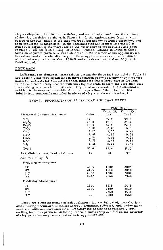
The a s h product consisted predominantly of well-rounded particles (beads) ranging from about 1/16 to 1 / 4 inch in diameter, sometimes accompanied by some angular coke particles (Figure 2a).
Beads f r o m an early run (No. 17) were subjected to detailed examination. The air- to-s team ratio in this test was about 4:l by weight: temperature i n the fluidized bed ranged from about 1880' to 1930".
For microscopic observation the beads were mounted in epoxy resin, sectioned, and polished. A composite photomicrograph of a whole 1 -inch briquet, taken with vertical illumination, is shown in Figure 3. Residual coke appears as light a r e a s here , both a s the main constituent of the angular particles and a s the very small constituent particles of the rounded beads. These small particles a r e situated mostly on the periphery of the beads, although a few a r e buried in the interior.
The many rounded black a r e a s in the bead a r e empty vesicles. Others, connected by passageways to the exterior, were filled with the epoxy resin during mounting. (The system is evacuated before covering the sample with the resin, and the liquid resin is forced into some of the vesicles by the readmitted atmo- spheric pressure.)
A composite photomicrograph of the same briquet taken with oblique illumina- tion is shown in Figure 4. W i t h this illumination, the continuous phase of glassy, melted a s h in the rounded beads can be distinguished from many of the embedded, unmelted particles,
We did not attempt to identify all of the unmelted a s h particles; however, we think that some with high reflectance a r e probably particles of high-alumina r e - fractory f rom the walls of the unit. When the reflectances of some of these high- reflectance particles were measured, they agreed with that of the similarly mounted refractory. Very small vesicles in the melted ash appear a s pinpoints of reflected light. Some of the large, empty vesicles a r e partly illuminated on one side.
The distribution of the residual carbon indicated by microscopic observation was substantiated by further investigation: A sample of the residue was separated by hand into beads and angular particles; analyses for carbon then showed only 1.9 weight percent in the beads and 70.4 weight percent in the angular particles. That most of the residual carbon in the beads is not embedded and i s available for reaction was shown by igniting a sample of the beads for 112 hour at about 1550°F, followed by an analysis for unburned carbon. remained.
Only 0. 36 weight percent
The surface energy of a melt (or solid) of this kind i s high compared with that of carbonaceous solids, and thus melted a s h does not wet or spread on the low- energy surface of the coke (7). This is confirmed by the observation (under the microscope) that coke particles appear to float on the surface of the glassy phase, a s shown in the photomicrograph of Figure 5. The observed apparent contact angle between coke and the glassy phase varied from about 90 degrees to much more than that. This explains why so little coke is entrapped inside the melted ash.
125
We investigated the composition of the continuous or melt phase of the beads. Microscopic observations of polished sections (at higher magnification than s h o w in Figures 3 and 4) show the presence of crystals. The view in thephoto- micrograph of Figure 6 is typical, but occasional a r e a s a re found where the crystals a r e larger and comprise a larger fraction of the crystal-in-glass composite. Occasional particles of ferrous oxide and metallic iron have also been found and identified by measuring their reflectance. X-ray emission spectra of the crystals, obtained with a scanning electron microscope, indicated presence of i ron and aluminum. Iron, aluminum, and silica were similarly identified as the major components of the matrix or continuous phase; titanium, potassium, and calcium were a l so detected in it.
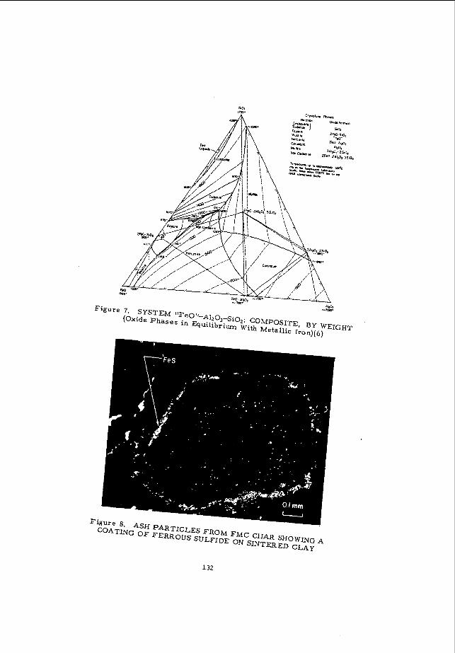
It is well known that the fusibility of ash containing substantial amounts of iron (from pyrite in the original coal) depends on the oxidation-reduction potential of the atmosphere. The presence of occasional par t ic les of metallic iron in the beads indicates that the atmosphere in a t least some zones of the bed was reducing enough for reduction of fe r rous oxide, although the product g a s generally had too low a carbon monoxide-carbon dioxide ratio to expect such reduction. The phase diagram for the Fe0-A1,03-SiQ system in equilibrium with metallic iron i s thus of interest for a n understanding of the a s h behavior.
The phase diagram of Osborn and Muan (6) for the FeO-Al,O,-SiQ system under this condition is shown in Figure 7. for crystallization of i ron cordierite, 2Fe0. 2A1203. 5SiQ. The minimum liquidus temperature in the presence of hercynite (FeO. Al2O3) and fayalite (2FeO. SiO,), a t the lower left corner of the field, is 1990t9OF. However, i ron cordierite tends not to crystallize in the absence of seed crystals , and instead a metastable eutec- t ic of fayalite, hercynite, and tridymite may form at 1963~9'F (5). In the pre- sence of impurities, s t i l l lower liquidus temperatures may occur. Thus, Snow and McCaughy, working with mixtures prepared from clays containing im- purities, found a liquidus temperature of 1778OF for this eutectic (9). However, n o crystals typical of a eutectic were seen either by optical o r scanning electron microscopy, nor was any fayalite detected by X-ray diffraction. appears that a g lass is formed when the melted ash cools.
Aeelomerated Ash from FMC Char
Note the narrow quadrilateral field
Instead, i t
The FMC char was much more reactive than the coke breeze, resulting in a lower bed temperature with comparable gas feed. severe operating conditions (higher temperature or higher a s h content of the bed) were required to obtain agglomerates large enough to be discharged automatically and in sufficient quantity to maintain the ash content of the bed in a steady state without periodic dumping. Steam had to be eliminated from the gas feed to obtain the required temperatures.
On the o the r hand, more
Agglomerated par t ic les f rom two runs operating with FMC char a s feed (Nos. 57 and 60) were examined. The feed for the f i r s t of these runs had been prepared from I l l ino is coal and that for the latter f rom Western Kentucky coal.
The agglomerated a s h particles differed considerably f r o m those produced f rom the coke breeze, being smaller and subangular instead of well-rounded. Par t ic les from Run 6 0 a r e shown in Figure Zb with small beads from coke for comparison. In polished sections under the optical microscope, the clay of the coal ash appeared to be well-sintered, but no ferrous aluminum silicate was detected by X-ray emission in the scanning electron microscope. Instead, the i ron appeared most ly in the form of ferrous sulfide and magnetite. chars, the iron appeared a s ferrous sulfide; in the agglomerated ash from an early period of Run 57, some magnetite had appeared, but mos t of i t was ferrous sulfide, much of i t a s separate particles. Some was occluded in the agglomerated
In both feed
126
clay a s dispered. 1 to 1 0 - p - ~ particles, and some had spread over the surface of the clay particles a s shown in Figure 8. period of the run, much of the exposed iron, but not the occluded particles, had been converted to magnetite. In the agglomerated ash from a late period of Run 60, a portion of the magnetite on the outer zone of the particles had been reduced to wcstite (FeO). Rings of ferrous sulfide, similar in shape to those found on separate particles, were observed in the interior of the agglomerates. Formation and automatic discharge of these agglomerates occurred in Run 60 with a bed temperature of about 1950°F and an a s h content of about 50% in the fluidized bed.
DISCUSSION
In the agglomerates f rom a la ter
Differences in elemental composition among the three feed mater ia ls (Table 1 ) a r e probably not very significant in interpretation of the agglomeration process; however, analysis for acid-soluble i ron indicated that a large par t of the iron in the coke had already reacted with the clay minerals to form the acid-insoluble, low -melting ferrous aluminosilicate. acid but is decomposed o r oxidized in the preparation of the coke and char. Soluble i ron compounds occluded in sintered clay also do not dissolve. )
(Pyri te also is insoluble in hydrochloric
Table 1. PROPERTIES OF ASH I N COKE AND CHAR FEEDS
Elemental Composition, wt % Si02 A1203 Fez03 Ti02 CaO MgO NazO Kz 0 so3 Total
Acid-Soluble Iron, % of total iron
Ash Fusibility, O F
Reducing Atmosphere
IT ST HT FT
Oxidizing Atmosphere
IT ST HT F T
Coke
47. 1 20. 8 18. 9
0. 81 3. 25 1. 01 0. 54 1. 72 2. 26
96. 4
47
2085 2155 2230 2440
2510 2630 - -
_ _
FMC Char F r o m Ill. F r o m Ky.
Coal Coal
35. 7 39. 9 17. 5 23. 4 24. 1 24. 1
0. 88 0. 51 3. 50 0. 43 0. 85 0. 74 4. 03 0. 60 2. 48 0. 65 5. 15 1. 95
93. 4 92. 3
98 97
- -
1780 2005 1950 2050 1980 2080 2160 2340
2215 2475 2300 2520 2360 2540 2500 2560
Thus, two different modes of a s h agglomeration a r e indicated, namely, i ron oxide fluxing (formation of molten ferrous aluminum silicate), and, under m o r e severe conditions, clay sintering. melting (and thus prone to sintering) ferrous sulfide (mp 218O0F) on the exterior of clay particles may have aided in their agglomeration.
Possibly the presence of relatively low-
127
prediction of the performance that will be obtained with other types of feed is uncertain. The f o r m of the iron in the feed is obviously important; iron in hydrogasification residue, for example, i s likely to have been converted to ferrous oxide and would thus be in a much readier form to react with and flux the clay than it i s in char. This may also be the case even with raw coal a s the feed, because a gasification atmosphere has a higher oxidation potential than a pyrolysis atmosphere does.
ACKNOWLEDGMENTS
This work was conducted a s par t of the HYGAS@ coal gasification program jointly sponsored by the United States Energy Research and Development Administration (ERDA) and the American Gas Association. under the technical direction of Dr . C. Lowell Miller and Mr. Stephen C. Verikios of ERDA and Dr. Ab Flowers of the American Gas Association.
REFERENCES
This program i s
1. ASTM 1975 Annual Book of ASTM Standards, Part 26 -Gaseous Fuels: Coal and Coke: Atmospheric Analysis. D 2797 , "Preparing Coal Samples for Microscopical Analysis by Reflected Light. " Philadelphia: American Society for Testing and Materials, 1975.
2. Boar, P. L. and Ingram, L. K . , "Comprehensive Analysis of Coal Ash and Silicate Rocks by Atomic -Absorption Spectrophotometry by a Fusion Technique," Analyst (London) 95 (1127), 124-30 (1970).
3. Cameron, E. N. , Ore Microscopy. New York: John Wiley, 1961.
4.
5.
6.
7.
8.
9.
Mason, D. M. and Schora, F. C., Jr. , "Coal and Char Transformation in Hydrogasification," Adv. Chem. Ser. No. 9, 18-30 (1967).
Muan, A. , "Phase Equilibrium Relationships a t Liquidus Temperatures in the System FeO-Fe,0,-A120,-SiQ, " J. Amer. Ceram. SOC. 4J 420-31 (1 95 7 1. Osborn, E.F. and Muan, A., in Levin, E. M., Robbins, C.R. and McMurdie, H. F., Eds. , Phase Diagrams for Ceramists, 241. Columbus: The American Ceramic Society, 1964.
Raask, E. , "Slag -Coal Interface Phenomena, " J. Eng. Power (No. I), 40-44 (1966).
Sandstrom, W.A. , Rehmat, A. G. and Bair, W. G. , "The Gasification of Coal Chars in a Fluidized-Bed Ash-Agglomeration Gasifier. ' I Paper presented a t the A. I. Ch. E. 69th Annual Meeting, Chicago, November 28 - December 2, 1976.
Snow, R.B. and McCaughy, W. J., "Equilibrium Studies in the System FeO-Al,O,-SiQ, " J. Amer. Ceram. Soc. 25, 151 -60 (1942).
128
ZNDSTIIGE C Y M N E I
LOCKHOPPERS
ASH AGGLOMERATES
Figure 1. SCHEMATIC DIAGRAM O F ASH-AGGLOMERATING GASIFIER
Figure 2b. ASH AGGLOMERATES FROM Figure 2a. ASH AGGLOMERATES FROM
COKE, WITH COKE PARTICLES FMC CHAR AND (Right)
129
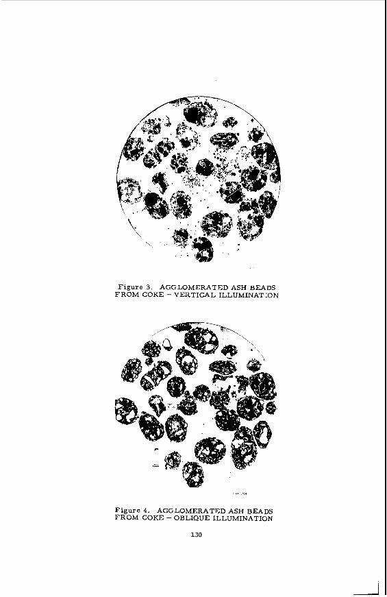
Figure 3. AGGLOMERATED ASH BEADS FROM COKE - VERTICAL ILLUMINATION
Figure 4. AGGLOMERATED ASH BEADS FROM COKE - OBLIQUE ILLUMINATION
130
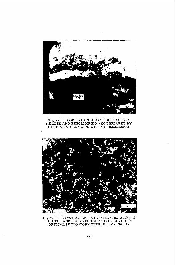
Figure 5. COKE PARTICLES ON SURFACE OF MELTED AND RESOLIDIFIED ASH OBSERVED BY
OPTICAL MICROSCOPE WITH OIL IMMERSION
Figure 6. CRYSTALS O F HERCYNITE (FeO- AlzO,) IN MELTED AND RESOLIDIFIED ASH OBSERVED BY
OPTICAL MICROSCOPE WITH OIL IMMERSION
131
E
132
Petrochemistry of Coal Ash Slags. 1. Formation of Melilite and a High Temperature Glass from a Calcium-Rich, Silica-Deficient Slag.
21 4 / H. H. Schobert,L/ D. L. Barbie,- 0. D. Christensen,z' and F. R. Karnex-
Grand Forks Energy Research Center Box 8213, University Station
Grand Forks, ND 58202 and
Department of Geology University of North Dakota Grand Forks, NE 58202
The Grand Forks Energy Research Center (GFEXC) of the Energy Research and Development Administration is conducting pilot plant studies of a fixed-bed slagging coal gasification process. The pilot plant was originally operated from 1958-1965 by the Bureau of Mines. Mines test results have been documented (2,g). Recent papers (3,i) have described the program objectives for the reactivated plant and have presented some prelimi- nary results.
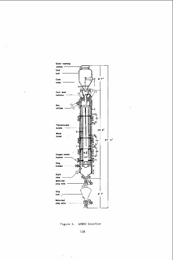
The design and operation of the gasifier and the Bureau of
A schematic diagram of the gasifier is shown in Figure 1. Lignite or subbi- tuminous coal is reacted with steam and oxygen at pressures to 27 atmospheres psig and at hearth zone temperatures exceeding 1650' C. which 90% is carbon monoxide and hydrogen at 2:l ratio and the balance is composed of methane, carbon dioxide, and nitrogen. The hearth zone temperatures are main- tained sufficiently high to cause melting of the ash. The molten slag drains into a water quench bath through a taphole in the hearth. Maintaining a steady flow of slag is crucial to the successful operation of the gasifier, since a build-up of slag on the hearth o r a plug forming in the taphole will result in a premature shutdown of the test.
A gas mixture is produced of
The petrochemistry of the slag is of considerable importance as a factor in hearth section design. relationship between slag constituents and the refractories. If a phase trans- formation in the slag should produce a liquid having a composition well outside the design specifications, a rapid chemical degradation of the refractory struc- tures could occur. The temperature dependence of slag viscosity is a function of slag composition. Since design of slag discharge orifices w i l l be influenced in part by the expected viscosity range, viscosity changes caused by corresponding composition changes could alter slag flow characteristics.
Refractory selection will depend in part upon the chemical
Additional interest in slag petrochemistry arises from a similarity of slag compositions to naturally-occurring silicate melts. in the gasifier can provide opportunities for studies of igneous rock petrology.
Thus the slagging operations
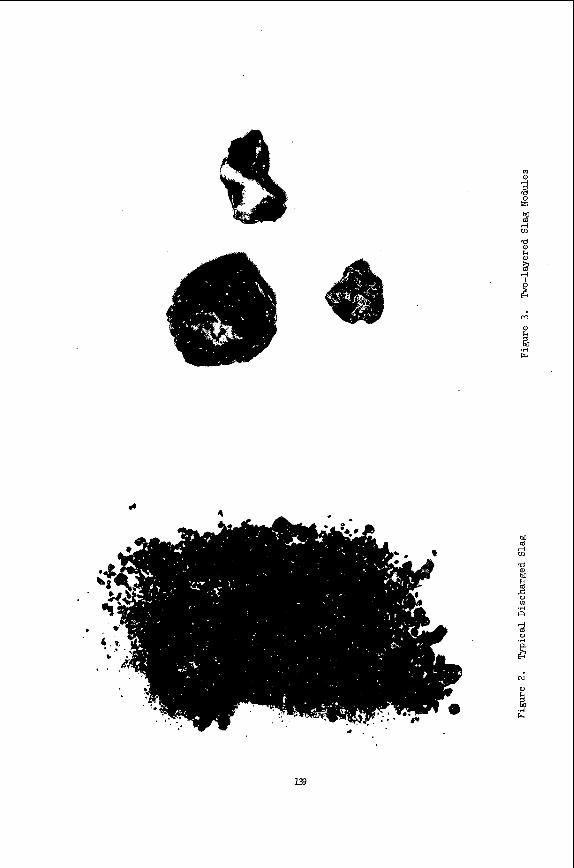
During operation, the slag is removed from the gasifier by periodically discharging the slag lock. granules (Fig. 2).
The discharged slag is recovered as black, glassy In some tests the slag has been found to contain structures Of
- 1/ - 2/ 3/ g/
Research Chemist, Grand Forks Energy Research Center. Physical Science Aide, Grand Forks Energy Research Center. Assistant Professor of Geology, University of North Dakota. Professor of Geology, University of North Dakota.
133
unusual o r a typica l appearance. i c a l and petrographic analysis . It i s of Par t icu lar concern t o i d e n t i f y t h e phases formed, t o determine or suggest t h e mechanism of t h e phase separat ion, and t o pred ic t t h e e f f e c t on such parameters as r e f r a c t o r y ' a t t a c k , s lag v iscos i ty , and heat t ransfer .
Samples of these a r e re ta ined f o r de ta i led chem-
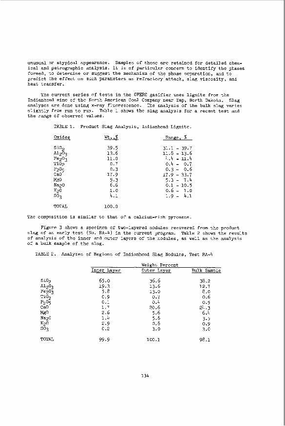
The current s e r i e s of t e s t s i n the GFERC g a s i f i e r uses l i g n i t e from t h e Indianhead mine of t h e North American Coal Company near Zap, North Dakota. Slag analyses a r e done using x-ray fluorescence. s l i g h t l y from run t o run. Table 1 shows t h e s l a g ana lys i s f o r a recent t e s t and t h e range of observed values.
The analysis of t h e bulk s lag var ies
TABLE 1. Product Slag Analysis, Indianhead Ligni te .
Oxides
Si02 *l2O3 Fe203 Ti02 P205 C a O MgO Nap0 K20 so3
39.5 13.6 11.0
0.7 0.3
17.9 5.3 6.6 1 . 0 4 . 1
Range, %
31.1 - 39.7
4.4 - 11 .4 0.4 - 0.7 0.3 - 0.6
11.8 - 13.6
17.9 - 33.7 5.3 - 7.4
0.6 - 1.0 1.9 - 4 . 1
0 .1 - 10.5
TOTAL 100.0
The composition i s s i m i l a r t o t h a t of a calcium-rich pyroxene.
Figure 3 shows a specimen of two-layered nodules recovered from t h e product s l a g of an ear ly t e s t (No. RA-4) i n the current program. Table 2 shows t h e r e s u l t s of ana lys i s of t h e inner and outer layers of t h e nodules, as well as t h e analysis of a bulk sample of t h e s lag.
TABLE 2. Analyses of Regions of Indianhead Slag Nodules, Test FA-4
Weight Percent Inner Layer Outer Layer Bulk Sample
Si02 A1203 Fe203 Ti02 p2°5 CaO
65.0 19.3
5.8 0.9 0.1 1 . 7 2 .6 1.4 2.9 0.2
36.6 13.6 13.0
0.7 0.4
20.6 5.6 5.8 0.8 3.0
38.2 12.7 8.0 0.6 0.5
24.3 6.4 3.5 0.9 3.0
TOTAL 99.9 100.1 98.1
134

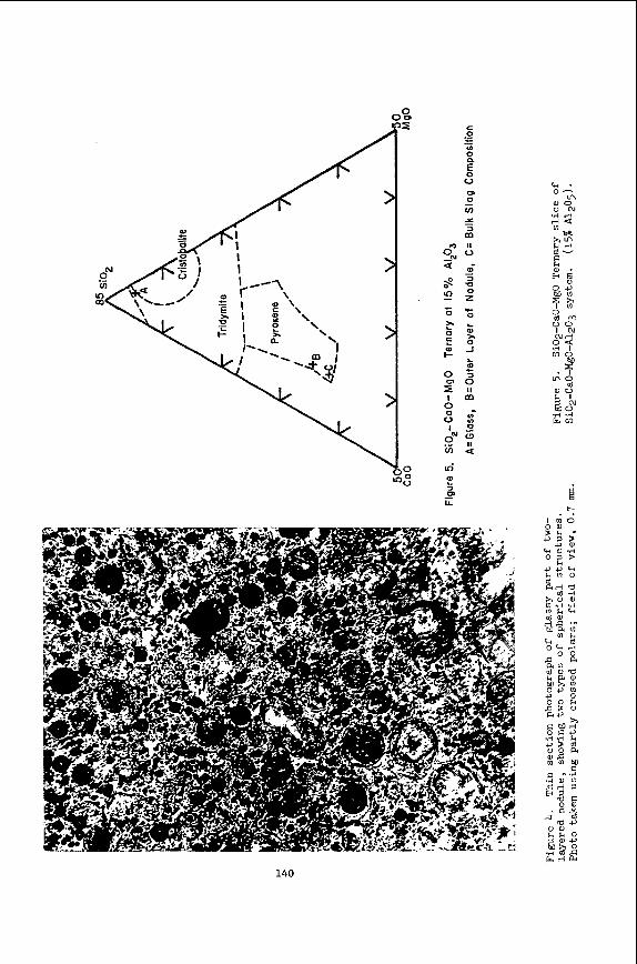
A t h i n sect ion of one of these nodules i s shown i n Figure 4 . Optical and x-ray d i f f rac t ion study shows t h a t the inner mater ia l i s a ves icu lar g lass with a small amount of disseminated quartz grains or fragments. across t h e thin-sectioned chips , typ ica l ly occurring i n zones of smaller (0 .01 mm) and la rger (0.04 mm) approximate average diameter. numerous s imi la r , spherical s t ruc tures with pa le t a n color a r e present . These of ten contain or par t ly contain quartz grains . s imilar t o the or ig ina l s lag.
The ves ic les vary i n s i z e
In addi t ion t o t h e ves ic les ,
The outer layer of t h e nodules i s very
Figure 5 shows a port ion of a Si02-Ca0-Mg0 te rnary s l i c e through t h e Si02- CaO-MgO-Al203 quarternary system, a t 15 pct Al2O3. bas i s of Si02 + CaO + MgO + A1203 = 100 p c t ) . The composition of t h e inner layer l i e s i n t h e c r i s t o b a l i t e f i e l d , while both t h e outer l a y e r and bulk s lag composi- t ions l i e i n the pyroxene f i e l d . The fac t t h a t c r y s t a l l i z a t i o n of t h e inner l a y e r was not more pronounced is very l i k e l y due t o undercooling, s ince reported (5) s lag discharge temperatures of 2300' F (1260' C ) a r e l e s s than 100' C above t h e f l u i d temperature of Indianhead s lag.
(Points a r e p lo t ted on t h e
The three-layered nodules were recovered from t h e s lag i n a more recent t e s t (RA-7). t h e bulk s lag.
TABLE 3.
The analysis of each layer i s given i n Table 3, along with an analysis of
Analyses of Regions of Indianhead Slag Nodules, Test RA-7
Inner Layer
Si02 36.6 A1203 10.2 Ti02 0.3
0.5 p205 CaO 40.5 MgO 7.9 Nap0 0.3 K20 0.3
3.1 0.2
so3 Fe203
Middle Layer
37.8 8.9 0.3 0.5
38.7 9.5 0.5 0.3 2.5 1 .0
Outer Layer
39.2 12.5
0.5 0.5
31.1 6.8 1.2 0.6 1 . 4 6 .1
Bulk Sample
33.1 1 3 . 1
0.5 0.6
22.6 5.4 6.1 0.8 2.4
1 1 . 4
TOTAL 99.9 100.0 99.9 96.0
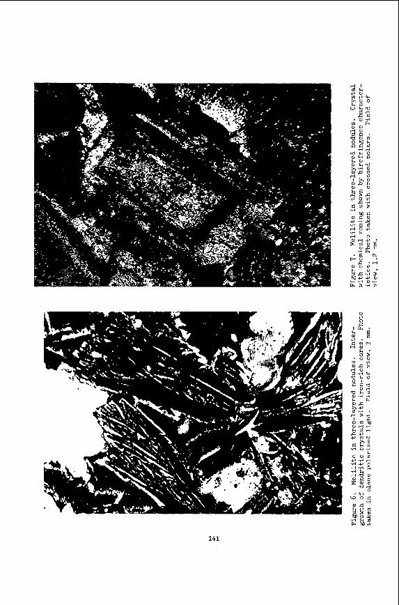
Thin sect ion photographs of a three-layered nodule a r e shown i n Figures 6 and Optical and x-ray d i f f r a c t i o n da ta show t h a t the inner layers contain abundant 7.
m e l i l i t e while t h e outer core i s a glass . Mel i l i t e occurs as two types of clus- t e r s of rad ia t ing , zoned c r y s t a l s . One type has zoning produced by dark, reddish cores, probably resu l t ing from abundant iron-rich inclusions and exhib i t s a wel l developed dendri t ic intergrowth tex ture , probably from quenching. The second type of m e l i l i t e has zoning shown by birefringence c h a r a c t e r i s t i c s , probably from osc i l la tory o r reverse chemical zoning and subhedral t o euhedral c r y s t a l form.
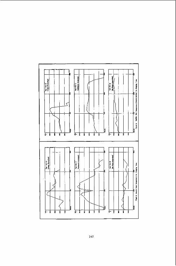
I n both cases these phase transformations can be r e l a t e d t o temperature f luctuat ions i n t h e g a s i f i e r hear th . Hearth zone temperatures a re measured by a thermocouple mounted on t h e bottom of t h e hear th p l a t e , and another i n the gasi- f i e r w a l l approximately 5-112 f e e t above the hearth. Figures 8 and 9 show t h e two temperatures a s a function of time f o r t e s t s RA-4 and RA-7, as well as t e s t FA-8, i n which no s lag phase separat ion was observed. Temperature data from FA-4 and RA-7 show sharp f luc tua t ions , whereas the da ta from RA-8 show r e l a t i v e l y s tab le temperatures.
135

The s lag-refractory chemistry w a s found not t o be s ign i f icant ly affected by e i t h e r phase t ransformation described here. The s lags have been characterized by calculat ing t h e base t o acid r a t i o :
CaO + g o + Nap0 + K20 + Fe2O3
Si02 + A1203 + Ti02 B/A =
I n t h e case of g lass formation, t h e bulk s l a g has a b a s i c i t y / a c i d i t y r a t i o of 0.84, while t h e l i q u i d phase which would remain a f t e r formation of t h e g lass nodules has a value of 0.90 (ca lcu la ted from t h e ana lys i s of t h e outer layer of t h e nodules). The corresponding values f o r t h e m e l i l i t e formation a r e , respec- t i v e l y , 0.99 and 0.88. bas ic i ty . Accelerated chemical degradation of hear th zone r e f r a c t o r i e s is there- fore an unl ikely consequence of these phase transformations.
Neither s i t u a t i o n represents a d r a s t i c change i n s lag
Changes i n s l a g v i s c o s i t y were estimated by ca lcu la t ing v i s c o s i t i e s from a modified form of t h e Watt-Fereday equation (I_),
l o g II = 107M/(T-150)2 + C
where M and C a r e empir ical constants which a r e funct ions of s lag composition, t h e v iscos i ty i n poise , and t h e temperature i n degrees Centigrade. Preliminary r e s u l t s from current GFERC research on adapting t h e Watt-Fereday equation t o l i g n i t e s lags were used t o estimate order-of-magnitude v iscos i ty changes. calculated from t h e bulk s lag ana lys i s and from t h e ana lys i s of t h e outer layer of t h e nodules. Massive formation of m e l i l i t e from Indianhead s lag would leave a r e s i d u a l l i q u i d having a ca lcu la ted v iscos i ty of 125 poise a t 1350' C , while t h e calculated v i s c o s i t y of t h e bulk s lag i s only 8 poise.
Viscos i t ies were
The change i n s l a g v iscos i ty w i l l a l so a f f e c t hear th zone heat t r a n s f e r re la t ionships . For example, t h e ca lcu la t ion of t h e heat t r a n s f e r coef f ic ien t between the s lag and hear th p l a t e i s dependent upon t h e Grashof and Prandt l num- bers f o r the flowing s l a g , both of which a r e funct ions of v iscos i ty (g).
The r e s u l t s of t h i s study show t h a t t h e c h a r a c t e r i s t i c s of t h e coa l ash s lag can be affected by temperature f luc tua t ions i n t h e g a s i f i e r hear th . Chemical, flow, and heat t r a n s f e r behavior a r e a l l suscept ible t o change as a r e s u l t .
REFERENCES
G.H. Gronhovd, A.E. Harak, W.R. Kube, and W.H. Oppelt. "Design and I n i t i a l Operation of a Slagging, Fixed-Bed, Pressure Gasif icat ion P i l o t Plant." U.S. Bureau of Mines R I 6084 (1962).
G.H. Gronhovd, A.E. Harak, M . M . Fegley, and D.E. Severson. "Slagging Fixed- Bed Gasif icat ion of North Dakota Ligni te at Pressures t o 400 psig." Bureau of Mines R I 7408 (1970).
R.C. Ellman and B.C. Johnson. "Slagging Fixed-Bed Gasif icat ion a t t h e Grand Forks Energy Research Center." Gas Symposium, Chicago, I L , October 1976.
U.S.
Presented at t h e Eighth Synthetic Pipel ine
136

4. R.C. Ellman and H.H. Schobert. "Pi lot Plant Operation of a Fixed-Bed Slagging Gasifier." Society, New Orleans, LA, March 1977.
Presented at t h e National Meeting of t h e American Chemical
5. G.H. Gronhovd. "Quarterly Technical Progress Report, April-June, 1976." ERDA Report GFEXC/QTR-76/4 (1976).
6. B. Mason. "Principles of Geochemistry." Second Ed., John Wiley and Sons, Inc , New York, NY 1958.
7. J . D . Watt and F. Fereday. "The Flow Propert ies of Slags Formed From t h e Ashes of B r i t i s h Coals: Par t 1: Viscosi ty of Homogeneous Liquid Slags i n Relat ion t o Slag Composition." J. I n s t . Fuel, 42, 99 (1969).
8. C.O. Bennett and J . E . Myers. "Momentum, Heat, and Mass Transfer." Second Ed., McGraw-Hill Book Co., New York, NY 1974.
137
Quick -opening closura Cod
3
Figure 1. GFERC Gasifier
138
m 0)
2 .rl a
e
140
d
f k V
10
G
a .rl
t-
.rl i F
. k w o
I m
CI 0
a e .rl
u ld rl a C
c M
1 4 2