membranes for water treatment: properties and characterization · advanced membrane technologies...
TRANSCRIPT
Advanced Membrane TechnologiesStanford University, May 07, 2008Advanced Membrane TechnologiesStanford University, May 07, 2008
Ingo Pinnau, Ph.D.
Membranes for Water Treatment:Properties and Characterization

Membrane Separation Processes and CharacteristicsMembrane Separation Processes and Characteristics
Molecular(Nonporous)
< 10Solution/Diffusion
ReverseOsmosis (RO)
Mesopores20 - 500Size ExclusionUltrafiltration(UF)
Macropores500 - 50,000Size ExclusionMicrofiltration(MF)
Macropores> 50,000Size ExclusionParticleFiltration
TransportRegime
Pore Size (Å)
SeparationMechanism
Process
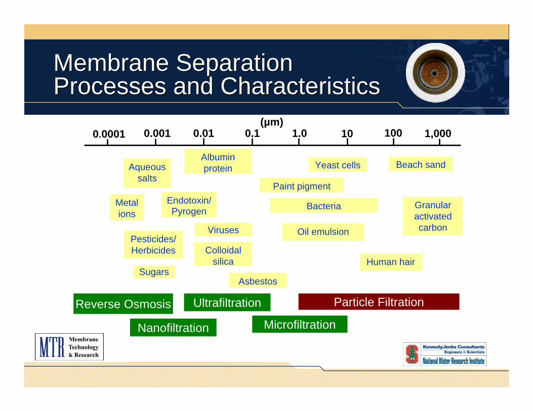
Membrane Separation Processes and CharacteristicsMembrane Separation Processes and Characteristics
0.001 0.01 0.1 1.0 10 100 1,000
Beach sand
Granular activated carbon
Human hair
Yeast cells
Bacteria
Paint pigment
Oil emulsion
Albumin protein
Endotoxin/ Pyrogen
Colloidal silica
Asbestos
Pesticides/ Herbicides
Aqueous salts
Viruses
Metal ions
0.0001(µm)
Sugars
Reverse Osmosis
Nanofiltration
Ultrafiltration
Microfiltration
Particle Filtration

Membrane Characteristics:Porous MembranesMembrane Characteristics:Porous Membranes
MonovalentMonovalentionsions
MultivalentMultivalentionsions
SuspendedSuspendedsolidssolidsWaterWater VirusesViruses BacteriaBacteria
MicrofiltrationMicrofiltration
MonovalentMonovalentionsions
MultivalentMultivalentionsions
SuspendedSuspendedsolidssolidsWaterWater VirusesViruses BacteriaBacteria
UltrafiltrationUltrafiltration

Membrane Characteristics:Non-Porous MembranesMembrane Characteristics:Non-Porous Membranes
MonovalentMonovalentionsions
MultivalentMultivalentionsions
SuspendedSuspendedsolidssolidsWaterWater VirusesViruses BacteriaBacteria
NanofiltrationNanofiltration
MonovalentMonovalentionsions
MultivalentMultivalentionsions
SuspendedSuspendedsolidssolidsWaterWater VirusesViruses BacteriaBacteria
Reverse Reverse OsmosisOsmosis

Ideal Membranes for UF, NF and RO ApplicationsIdeal Membranes for UF, NF and RO Applications
High water flux (low capital cost)High solute rejection (high water purity)Long-term stability of water flux and rejection(Membrane fouling)Mechanical, chemical and thermal stabilityMinimum pre-treatment (backflushing and chemical treatment)Can be processed into large-scale membranes and modulesInexpensive!

Problems of Current Membranes Used in UF and RO ApplicationsProblems of Current Membranes Used in UF and RO Applications
Poor long-term stability of water flux(Membrane Fouling)
Backflushing and chemical treatment
High membrane replacement cost
Poor resistance to chlorine
Membrane system size

Major Foulant Types in Natural and Industrial WastewaterMajor Foulant Types in Natural and Industrial Wastewater
ScalingScaling
ColloidalColloidalFoulingFouling
BiofoulingBiofouling
OrganicOrganicFoulingFouling

Surface Structure of a Typical UF MembraneSurface Structure of a Typical Surface Structure of a Typical UF MembraneUF Membrane

Membrane Separation Processes and CharacteristicsMembrane Separation Processes and Characteristics
Porous SurfacePorous Surface
UnfouledUnfouled MembraneMembrane Fouled Membrane
Surface Fouling
Internal Fouling

Schematic Structures of Porous and Non-Porous UF MembranesSchematic Structures of Porous Schematic Structures of Porous and Nonand Non--Porous UF MembranesPorous UF Membranes
Microporous Ultrafiltration MembraneSelective skin layerSelective skin layer
Porous substratePorous substrate
Non-Porous Ultrafiltration Membrane
NonNon--porous hydrophilicporous hydrophilicSurface coating (0.1Surface coating (0.1--0.5 0.5 µµm)m)
Porous substratePorous substrate

Cross-Section of a Non-PorousUF MembraneCross-Section of a Non-PorousUF Membrane
Nonporous PolymerNonporous PolymerCoating LayerCoating Layer(~ 0.3 (~ 0.3 µµm)m)
MicroporousMicroporousSupport MembraneSupport Membrane

Long-Term Water Flux of Porous and Non-Porous Ultrafiltration MembranesLong-Term Water Flux of Porous and Non-Porous Ultrafiltration Membranes
10
100
1,000
0 5 10 15 20 25 30 35
Water flux(L/m2•h)
Permeation Time (Days)
Microporous PVDF module
Non-porousPebax 1074/PVDF
module
water flushwater flush
pure water Feed: 1% motor oil in waterFeed pressure: 150 psigFeed temperature: 23°C

Fouling Index of Porous and Non-Porous Ultrafiltration Membranes for Separation of Oil/Water Emulsions
Fouling Index of Porous and Non-Porous Ultrafiltration Membranes for Separation of Oil/Water Emulsions
0.01
0.1
1
0 5 10 15 20 25 30 35
Fouling Index H2O(t)/JH2O(0)
Permeation Time (Days)
MicroporousPVDF module
Pebax 1074 module
pure water
water flushwater flush

Long-Term Permeation Properties of Porous Ceramic and Ceramic/Polymer Composite Membranes
Long-Term Permeation Properties of Porous Ceramic and Ceramic/Polymer Composite Membranes
0
0.5
1
1.5
2
2.5
0 20 40 60 80 100 120
Permeation Resistance
(psi/gfd)
Time (hours)
Backflush
Ceramic Module
Ceramic/Pebax 1074Module
Feed: Bilge water ; permeate flux: 40 gfd

Membrane Types Used in Ultrafiltration, Nanofiltration and Reverse Osmosis
Membrane Types Used in Ultrafiltration, Nanofiltration and Reverse Osmosis
Integral asymmetric membrane (Cellulose acetate)Integral asymmetric membrane (Cellulose acetate)
Selective layer (Material A)
Microporous substrate(Material A)
ThinThin--film composite membrane (Polyamide)film composite membrane (Polyamide)
Selective layer (Material A)
Microporous substrate(Material B)

2003 RO/NF Membrane Sales2003 RO/NF Membrane Sales
444
58
11
3034
Share (%)
15Others12TriSep15Toyobo
18Koch/Fluid Systems
27GE Osmonics36Toray
99Nitto Denko/ Hydranautics
115Dow/FilmtechSales ($ MM)Company
R. Truby, Water Executive, September/October 2004, p.11 (Supplement of Ultrapure Water 21, 2004)

4Plate-and-frame
5Cellulose acetate hollow fiber
module
91Polyamide spiral-wound(8’x40’)
Market Share (%)Module Type
•• Expected RO/NF membrane lifetime ~ 3Expected RO/NF membrane lifetime ~ 3--5 years.5 years.•• Actual RO/NF membrane lifetime ~ 7Actual RO/NF membrane lifetime ~ 7--12 years.12 years.•• Membrane replacement makes up for ~ 60% of annual sales.Membrane replacement makes up for ~ 60% of annual sales.
R. Truby, Water Executive, September/October 2004, p.9 (Supplement of Ultrapure Water 21, 2004)
2003 RO/NF Module Sales Distribution

Incremental Changes in Spiral-Wound RO Module PerformanceIncremental Changes in Spiral-Wound RO Module Performance
Dave Furukawa (1999)
99.37.041.940.141999
30.83.521.660.191995
7.92.011.320.341990
2.61.561.100.651985
1.01.001.001.001980
Figure ofMerit
Reciprocal Salt Passage(Normalized to 1980)
Productivity(Normalized to 1980)
Cost (Normalized to 1980 U.S.$)
Year
Figure of Merit = (Productivity) x (1/Salt Passage)Cost

Interfacial Polymerization for Preparation of Thin-Film Composite RO MembranesInterfacial Polymerization for Preparation of Thin-Film Composite RO Membranes
Hydrocarbon/acid chloridesolution
Polyamide layer~ 0.1-0.2 µm
Aqueousaminesolution
Poroussupport
Heat cure

Formation of FT 30 Thin-Film Composite MembraneFormation of FT 30 Thin-Film Composite Membrane
NH2
NH2
ClOC
COCl
COCl
NH NHCO CO
CO
HN NHCO CO
COOH
n 1- n

Formation of PEC 1000 Thin-Film Composite MembraneFormation of PEC 1000 Thin-Film Composite Membrane
N N
NO
O
O
HOH2CH2C
CH2CH2OH
CH2CH2OH O CH2OHH2SO4
O CH2CH2N N
NO
O
O
CH2CH2
CH2CH2OCH2CH2CH2
N
N NCH2
O
HO3S
CH2 CH2CH2O
O
O
O

Rejection and Water Flux of RO Seawater Desalination MembranesRejection and Water Flux of RO Seawater Desalination Membranes

Organic Solute Rejection of Commercial RO MembranesOrganic Solute Rejection of Commercial RO Membranes

Surface Structures of InterfacialAromatic Polyamide Composite Membranes
Surface Structures of InterfacialAromatic Polyamide Composite Membranes
28 gfd 28 gfd
37 gfd 45 gfd
S.-Y. Kwak, D.W. Ihm, J. Membrane Sci. 158 (1999) 143-153

Cross-Section of Interfacial Polyamide Composite Membranes (BW 30)Cross-Section of Interfacial Polyamide Composite Membranes (BW 30)
Ridge and valleyRidge and valleystructurestructure~ 0.2 ~ 0.2 -- 0.5 0.5 µµmm
Selective layerSelective layer~ 500 ~ 500 -- 1,000 1,000 ÅÅ

Surface Structure of Uncoated and Coated RO MembranesSurface Structure of Uncoated and Coated RO Membranes
Uncoated Coated

Surface Structure of Uncoated and Coated RO Membranes (AFM)Surface Structure of Uncoated and Coated RO Membranes (AFM)
ESPA-3
ESPA-3 - coated
AFM pictures courtesy of Jennifer Louie, Stanford University

Performance of Commercial and Modified RO Membranes for Wastewater Treatment
Performance of Commercial and Modified RO Membranes for Wastewater Treatment
0
10
20
30
40
50
0 5 10 15 20 25 30
Water Flux
(L/m2•h)
Permeation Time (Days)
SWC-2
SWC-2/Pebax 4011
Feed: 900 ppm mineral oil; 100 surfactant DC 193Pressure: 500 psigTemperature: 25°C

AcknowledgementsAcknoAcknowledgements
Financial support was provided by Office of Naval Research and SERDP
Special thanks to my colleagues Isabelle Ciobanu, Sylvie Thomas and Alvin Ng.