mems inertial sensors - search read.pudn.comread.pudn.com/downloads165/ebook/756655/strapdown... ·...
TRANSCRIPT

7.1 Introduction
New applications that have demanded low-cost sensors for providing measurementsof acceleration and angular motion have provided a major incentive for the devel-opment of micro-machined electromechanical system (MEMS) sensors. One typicalmodern application is the use of inertial sensors in transport, such as motor cars; anindication of the current extent of the use of these devices in this application andexamples of many others are given in Chapter 15.
MEMS devices are one of the most exciting developments in inertial sensorsin the last 25 years. These devices overcome many of the features that have impededthe adoption of inertial systems by many potential applications, especially where cost,size and power consumption have been governing parameters. Many efforts involvingvalue engineering and automation have been applied to the design and manufactureof conventional inertial instruments, with significant success; however, the cost hasremained high. The major reasons centre on:
• high parts count;• requirement for many parts with high-precision tolerances;• intricate and precision assembly techniques;• accurate testing, characterisation and calibration.
The use of silicon as the base material in the manufacture of the componentsoffers a radical approach and overcomes many of the issues considered above forconventional mechanical sensors. This is summarised in Figure 7.1. Additionally,they can be considered as offering a sensing device on a chip with the very realprospect of a precision inertial measurement unit sensor on a chip in the near future.This holds the opportunity to make an inertial navigation system (with GPS aiding)costing less than $1000.
MEMS sensor technology makes direct use of the chemical etching and batchprocessing techniques used by the electronics integrated circuit industry. Precision
Chapter 7
MEMS inertial sensors

1955 1965 1975 1985 1990 2000
Numberof parts
Floatedgyros
Tunedgyros
Ringlasergyros
Fibreopticgyros
Vibratorygyros
MEMSgyros
Figure 7.1 Reduction in part count
techniques developed by this industry for 'machining silicon' have been adapted tomake very small mechanical structures using silicon or quartz. Particular advanceshave been obtained through the use of plane-wall etching. The properties of theresulting solid-state sensors, viz.
small size;low weight;rugged construction;low power consumption;short start-up time;inexpensive to produce (in high volume);high reliability;low maintenance;compatible with operation in hostile environments;
provide the engineer with a level of design flexibility beyond anything that has pre-ceded these developments. The consequence has been a proliferation of applications,both military and commercial, where such devices may be used; some of these arediscussed in Chapter 15.
The properties of silicon and the ease of perfecting high-fidelity componentswas a key breakthrough in the transition of this sensor technology from a researchdevice to a practical, mass-volume sensor. However, the reduction in size ofthe sensing elements brings with it challenges for attaining good measurementperformance and high resolution. In general, reductions in size give rise to decreasesin sensitivity/scale-factor and increases in noise. In addition, there are thermalsensitivity concerns; for example, the change in the Young's modulus of siliconwith temperature is ^100ppm/°C.
Despite these limitations, low-cost MEMS gyroscopes and accelerometersdemonstrating performance approaching l°/h and 50-100 micro-g, respectively, areexpected to become readily available within the next few years. One of the major

reasons for the enhanced performance of MEMS devices is the ability to undertakecomplex compensation of the systematic errors exhibited by these sensors, whichcan now be accomplished in real time. Complex or deep compensation methods relyon a very detailed knowledge of both the error mechanisms and the fundamentalcharacteristics of each sensor type and have to be embodied into the design of theKalman filter to give IMU-level compensation.
Moreover, recent research has given rise to an enhanced understanding of thephysical behaviour of the sensing element technology and the fundamental interac-tion with the supporting electronics used by these devices. These advances, alongwith sophisticated compensation techniques, have seen a dramatic increase in themeasurement accuracy. Over the last decade techniques have been demonstrated thatwill enable the measurement accuracy of the best quality devices to approach thoseof inertial-grade sensors, namely:
• angular rate measurement accuracy of 0.01°/h with MEMS gyroscopes;• specific force measurement to better than 1 milli-g from MEMS accelerometers.
Hence, there is the real prospect that such devices with enhanced performancewill displace ring laser and fibre optic gyroscopes in many tactical applications ina similar time scale.
Initial MEMS sensor developments focused on the generation of miniatureaccelerometers, the system and performance requirements of which were driven bythe demands of the automobile industry. As a result, MEMS accelerometer techno-logy was the first to achieve a level of technical maturity, with a significant numberof sensors now being commercially available.
In contrast, there was less of a stimulus for the development of similar angularmeasurement sensors, so commercially available devices in this class were slow toemerge initially. More recently, MEMS gyroscopic sensor development has been thesubject of significant investment and development effort in industry and researchinstitutions, both in Europe and the United States, culminating in the wide avail-ability of lower cost/lower performance sensors in recent years. Research effort hasconcentrated, and continues to be focused, on both the physics of the devices as wellas the refinement of the batch processing techniques required for their cost-effectivemanufacture leading to a high batch yield.
There are a number of reasons for the phenomenal increase in the performanceof the sensors during the last decade of the twentieth century; particularly plane-walletch. This has been a direct result of enhanced knowledge of the effects of geometryof the structure and its size, as well as the electronics and packaging, on the ultimateperformance and reliability of the devices. Moreover, there has been a significantinvestment in developing techniques for integrating all of the sensors on to a singlechip, which led to many system and performance benefits.
Hence these micro-miniature devices appear to be the sensors of the future. This isbecause they are based on a solid-state architecture and with careful design have fewcomponents and therefore have the potential to become the 'Holy Grail' for inertialsensor technology. Consequently, inertial sensor technology developments in recent

years have been concentrated almost exclusively on the development and perfectionof MEMS devices.
In the more distant future it is likely that further enhancements in performancecould show a similar trend. The miniature sensors of the future may well be basedon micro-opto-electromechanical systems (MOEMS). Currently, the technologyrequired to make a true MOEMS device with an optical read-out has not been reported.
This chapter sets out to summarise the advances in MEMS technology relat-ing to sensors designed to measure both angular rotation and linear acceleration.The physical principles of the operation of these devices are considered along withan attempt to predict the future technical performance of these devices.
7.2 Silicon processing
The use of silicon to make the sensing elements is attractive, as it is a proven routeto cost reduction through use of techniques developed in the semiconductor electron-ics industry for wafer processing. This industry has established very effective robustmethods for high-yield and high-volume production that lead to precision low-costcomponents. Moreover, the mechanical properties of crystalline silicon are inter-esting as it has a fracture limit of 7 GPa, which exceeds that of many steel alloys;additionally, its density is quite low at 2390 kg/m3. Hence, crystalline silicon is veryrobust and ideal for this application.
A range of manufacturing techniques has been devised and perfected over thelast three or four decades. These have concentrated on rapid and accurate etchingapproaches that avoid mechanical methods such as sawing, cleaving or filing. Themodern methods lead to components with flat surfaces and an absence of under-cutting. Efficient chemical 'machining' methods are very attractive, as they enablestress-free components to be produced rapidly. Moreover, the technique is capableof producing multiple components with identical dimensions to a high tolerance andhaving identical characteristics.
Silicon processing enables a robust design process to be devised. It is possible toreduce the fabrication process to three mask levels. For example, a 100 |xm wafer canhave a deposited oxide layer patterned with mask level 1, with a metal layer sputterdeposited and patterned with mask level 2. Finally, photo-resist is spun and patternedwith mask level 3 giving the shape of the resonator structure that is then generatedthrough a dry deep-trench etch technique. On completion of the etching process thephoto-resist is removed leaving a wafer of resonators.
The silicon wafer of resonators is anodically bonded to a pre-shaped glass waferand then diced to give individual sensor elements. This design technique avoids theneed to leave small gaps between the resonator and the surrounding material requiredfor conventional processing; consequently the problems associated with stiction aremitigated. Additionally with some designs, such as the ring resonator where thevibratory motion is in one plane, all of the silicon processing is planar, thus avoidingthe necessity for multi-layer processing.
Trade-off studies have shown that optimal gyroscopic performance is achievedwith sensing elements having a thickness in the region of 50-100 |xm. It is considered

that continued evolution of the advanced micro-machining processes are required tobuild thicker and more three-dimensional parts that have less critical tolerances onthe entire structure in order to reduce the cost of these sensors.
Another suitable material used as an alternative to crystalline silicon is quartz,and its application as the base material for MEMS inertial sensing devices is discussedlater in the chapter.
7.3 MEMS gyroscope technology
7.3.1 Introduction
MEMS gyroscopes operate on a very similar principle to that already described forvibrating gyroscopes, in Chapter 4. However, it will be described again here, but inthe context of a MEMS gyroscope.
MEMS gyroscopes are non-rotating devices and use the Coriolis accelerationeffect on a vibrating proof mass(es) to detect inertial angular rotation. Thus, thesesensors rely on the detection of the force acting on a mass that is subject to linearvibratory motion in a frame of reference which is rotating about an axis perpendicularto the axis of linear motion. The resulting force, the Coriolis force, acts in a direction,that is perpendicular to both the axis of vibration and the axis about which the rotationis applied. This is shown in Figure 7.2.
Whilst there are many practical sensor configurations based upon this principle,they fall generally into one of the three categories described below, and discussedpreviously in Chapter 4:
• simple oscillators;• balanced oscillators (tuning fork gyroscope);• shell resonators (wine glass, cylinder, ring oscillators).
Figure 7.3 provides a schematic illustration of these three angular sensors.
Rotation
Linear motion
Coriolis acceleration - ac = 2VxQ
Figure 7.2 Generation of Coriolis force

Simple beam oscillator Balanced oscillator Cylindrical shell
Figure 7.3 Classes of MEMS oscillator
Simple oscillators form the most basic class of vibratory gyroscopes; devicesbased on an oscillator that can be modelled as a single vibrating mass. The majordrawbacks in this type of design arise through mechanical asymmetry, resulting inadditional coupling between the axis of vibration and the output or measurementaxis, and sensitivity to external vibration and interaction of the vibrating elementwith the structure on which the instrument is mounted. The latter effect is attributableto the reaction forces exerted by the case of the sensor on the vibrating member. Oneof the more successful sensor designs, which fall into this category, is the vibratingwire sensor, as described in Chapter 4 (Section 4.4.8).
The problems associated with the sensitivity simple oscillators to external vibra-tion can be largely overcome by using a balanced oscillator. A device of this type thathas received considerable attention over the years is the tuning fork gyroscope (TFG),and a number of MEMS sensors based upon this principle have been produced usingeither quartz or silicon in their construction. As discussed later in the chapter, it isthe developments based around the TFG principle that have resulted in significantperformance improvements in recent years.
The third category for this type of sensor is the vibrating shell or ring device,which is symmetric about the axis of rotation. Sensors that fall into this categoryinclude the wine glass gyroscope and devices based on a vibrating cylinder or ring.Such devices are relatively easy to manufacture to a high level of accuracy.
MEMS devices have been implemented based upon a vibrating ring structure.For such a ring, the modes of flexural vibration may be classified as in-plane or out-of-plane modes. They occur in degenerate pairs at a mutual angle of 90/p degrees,where p is the number of modal diameters. Existing devices measure angular rateabout an axis perpendicular to the plane of the ring using the Coriolis coupling between

the in-plane modes. One mode is maintained at constant amplitude of vibration. Thecarrier mode may be excited by a number of methods including electromagnetic,electrostatic or piezoelectric means.
The vibrational behaviour of this type of sensor is considerably more complexthan that of the simpler single mass or balanced oscillator devices outlined above.However, such devices are also less susceptible to the effects of applied vibrationand the interactions between the vibrating element and the structure in which it ismounted.
As indicated above, the vibratory sensor types, which have been the focus ofrecent MEMS developments, have been based upon the principles of the tuningfork gyroscope and the vibrating ring device. Some examples of developments in thisfield of technology are described in the following sections.
7.3.2 Tuning fork MEMS gyroscopes
7.3.2.1 Silicon sensorsThe focus for much of the development of advanced performance silicon tuning forkgyroscopes has been, and continues to be, The Charles Stark Draper Laboratories,Inc. in the United States. In 1992, a team of engineers succeeded in implement-ing a Coriolis vibratory gyroscope using MEMS technology employing siliconwafer photolithographic and chemical etching processes adapted from the electronicsindustry. Since that time, as part of a continuing development process, gyroscopeshave been produced with an in-run bias stability in the region 3-10°/h over militaryoperating temperatures, falling to tenths of a degree per hour in a temperaturecontrolled environment with in-depth compensation techniques. Further dramaticimprovements in performance are anticipated over the next five years.
Whilst much of this development has been directed towards military applications,driving the quest for higher performance devices, it has also been licenced for com-mercial exploitation. The technology lends itself to high volume, low cost production($10 per axis) for more modest performance applications. The largest user in the nearterm is the automobile industry, where applications include gyroscopes for anti-skidbraking, steering control, roll detection and map navigation displays.
Principles of operationThe Draper micro electromechanical gyroscope, shown in Figure 7.4, consists ofa silicon structure suspended above a glass substrate. The silicon structure containstwo masses suspended by a sequence of beams that are anchored to the substrate atspecific points. These two masses are made to oscillate 180° out of phase throughthe application of voltages to the outer comb motor drives. This feature has led to thedesignation of the sensor as a tuning fork gyroscope; see Section 4.4.4.
The application of an angular rate about the input axis, which is perpendicularto the velocity vector of the masses, gives rise to a Coriolis force that acts to pushthe masses in and out of the plane of oscillation. Because the instantaneous velocityvectors of the relative masses are equal and opposite, anti-parallel motion is inducedin response to the Coriolis force. The resultant motion is measured by capacitor

Figure 7.4 MEMS comb-drive tuning fork gyroscope (© The Charles Stark DraperLaboratory, Inc. All rights reserved. Reprinted with permission)
plates above and below each of the two masses, providing a signal proportional to theapplied input rate. The operating elements of the gyroscope are shown schematicallyin Figure 7.5.
A simplified schematic is shown in Figure 7.6 to illustrate further the principleof operation. This diagram indicates the directions of vibration of the proof masswhen the device is rotated about its input axis.
This device, also known as an in-plane sensing device,1 is fabricated froma single crystal of silicon on Pyrex, the size of the proof mass element being1000 |xm x 1000 |xm x 20 |xm. The operating frequency is ~ 12 kHz, and the ampli-tude of the motion imparted to the proof mass is 10 |xm (peak). The sensor drive iselectrostatic and a capacitive pick-off is employed to detect the output motion of theproof mass.
The following values are given to put into context the precision of the measurementtask that needs to be undertaken in a MEMS gyroscope. For a typical device, a 1 rad/sinput rate results in a Coriolis force of approximately 9 x 10~8N, a peak motionalong the sense axis of 10~9 m, a 3 aF (aF = attofarad; 1 aF = 10~18 F) peak changein capacitance and a charge generation of 15 000-65 000 electrons.
As with all gyroscopes, the design of the electronics used to drive and controlthe sensors is a critical sub-system. This 'component' requires careful optimisationto give stable and repeatable output, in order to achieve good and reliable perfor-mance. For the particular device described here, the drive motor loop and the senseelectronics are particularly important. The motor loop comprises a self-drive oscil-lator that provides voltages to generate an electrostatic force to induce motion ofeach proof mass. This motion is sensed and controlled to sustain a constant driveamplitude. Detection of the Coriolis induced motion is carried out using a highly
1 Care must be taken in defining what is meant by 'in-plane' and 'out-of-plane' devices. 'In-plane'refers here to the orientation of the sensitive axis of the sensor, which in this case is parallel to the plane ofthe sensing element. It is noted that the resulting Coriolis motion of the sensitive element is perpendicularto the plane of the device (out-of-plane).

Top view
Left sense
Centremotor
Vibratingmass
Right sense
Leftmotor
Combstructure
Rightmotor
Flexuralsupport
Output
Vibrating masses
Side view
Rightmotordrive
Sense plate Rebalanceplate
Figure 7.5 Operating elements of MEMS tuning fork gyroscope (O The CharlesStark Draper Laboratory, Inc. All rights reserved. Reprinted withpermission)
sensitive capacitive pick-off. A pre-amplifier detects the charge generated throughchanges in proof-mass displacement. Existing devices operate in an open-loop mode,the output of the pick-off electronics providing a signal proportional to the inputrate. A block diagram representation of the MEMS gyroscope electronics is given inFigure 7.7.
Sensor fabrication and packagingSensors are manufactured by the dissolved wafer process, illustrated in Figure 7.8.The first step (Mask 1) involves the etching of recesses in a doped-silicon wafer,which defines the height of the silicon above the glass substrate and the gap spacing
Anchor point
Leftmotordrive
Centremotordrive
Glasssubstrate

Input angular rate
Figure 7.6 Motion of proof mass elements of a MEMS tuning fork gyroscope
for the capacitive sensing plates. A boron diffusion process follows, which definesthe thickness of the structure. The pattern features are defined by Mask 2 and are thenmicro-machined using a reactive ion etching process. The glass wafer is processedseparately, Mask 3 defining the glass recess and metal electrode pattern. The siliconwafer is then inverted and bonded to the glass wafer. This is followed by the finaletching process to dissolve the un-doped silicon and leave the free-standing device.Hundreds of sensors are made on a single wafer.
The device is hermetically sealed in a package, which has a vacuum maintainedin it to ensure the high-Q resonance is achieved to enable the desired operationalcharacteristics. Leadless chip carriers (LCCs) with braze-sealed lids have been usedin pilot production. Sensor chips are installed in packages using compression bondingand wire bond interconnections. The sensor package is then aligned mechanicallyon a printed circuit board containing the electronics. The resulting LCC is 0.25 in.2
by 0.1 in. high.
Plan view
Proof mass
Side viewProof mass
Sense electrodes

Figure 7.7 MEMS gyroscope electronics (© The Charles Stark Draper Laboratory,Inc. All rights reserved. Reprinted with permission)
Silicon Glass
MASK 1: Etch recess MASK 3: Recess and metal deposition
Diffuse boron Electrostatic bonding
Si-metal contact
MASK 2: RIE structure pattern Wafer etch in EDP
Figure 7.8 Dissolved wafer, silicon on glass process for gyro manufacture(O The Charles Stark Draper Laboratory, Inc. All rights reserved.Reprinted with permission)
Recent advances in the reactive ion etching process used in the manufacture ofMEMS gyroscopes have resulted in designs incorporating silicon proof masses withincreased component thickness up to 50 |xm. The additional thickness of the siliconproof mass is expected to yield greater stability and improved device performance.In addition, recent devices include both upper and lower glass-sense plates to give
Self drive oscillator loop
Driveforce Drive axis
dynamicsElectrical
comp.
Velocity Velocitysignal
2mQOutputnoise
Other forces Sense axisdynamics
ACgain
Filter andDC gain
Indicatedrate
Sense axis chain

increased signal-to-noise ratio. Further details concerning the fabrication of thesedevices and their drive electronics can be found in the literature [1-3].
PerformanceThe MEMS gyroscope described here is capable of measuring rotation rates of severalthousand degrees per second, whilst having the resolution to detect small fractions ofa degree per hour. Typical performance figures are tabulated in Table 7.1.
It is stressed that current MEMS sensors are heavily reliant on pre-run char-acterisation followed by calibration to remove turn-on errors and so achieve highperformance.
As with other solid-state technologies, such instruments are able to withstandhigh levels of mechanical shock and vibration, and hence are applicable for oper-ation in hostile environments. MEMS gyroscopes and accelerometers have alreadyfound application in guided-munitions' applications where they must withstand andoperate in the presence of launch accelerations of many thousands of gs. This featurecombined with their capability to provide precise rotational measurements, opens upmany new areas of application, many of which require in-depth investigation.
Since this is an emerging technology, it is felt to be appropriate to give someindication of performance expectations, as indicated by the performance goals given inTable 7.1. Gyroscopic performance improvements are expected to come about throughthe use of thicker and larger component parts; increased thickness of the silicon proof-mass in gyroscopes. This has become possible as a result of recent improvements inreactive ion etching techniques, allowing straight sidewall and flatness tolerances tobe met. This in turn leads to reduced susceptibility to fabrication tolerances, higherscale-factor and greater sensor performance stability. Although higher performance
Table 7.1 MEMS tuning fork gyroscope performance figures
Operating range (°/s)
Turn-on bias stability (°/h)
In-run bias stability (°/h)
Turn-on scale-factor stability (pp]
In-run scale-factor stability (ppm
Angle random walk (%/h)
^-Sensitivity (0IhJg)
Currentsensors
100-6000
10-150
3-300.3-10
m) 500-1500
) 300-1500100-300
0.01-0.3
10
Performancegoals
100-6000
<1
<1<0.1
<100
<100<10
0.01-0.03
0.5
Comments
Selectable
AU environments
-40 to 85°C5°C temperature range
All environments
-40 to 85°C5°C temperature range
Lower random walk atlower maximuminput rate

devices will be physically larger as a result of the developments outlined above, thesechanges will yield sensors that are still quite small in size and capable of fulfillingsize requirements for the types of application in which they are expected to be used.
7.3.2.2 Quartz sensors
A number of MEMS gyroscopes use quartz as the base material for the sensingelement. The use of piezoelectric quartz material simplifies the sensing element,resulting in a reliable and durable sensor that is stable over both temperature and time.
An example of this type of device is the quartz rate sensor (QRS) produced bythe Systron Donner Inertial Division of BEI Technologies, Inc. [4], and describedearlier in Section 4.4.5. A picture of this device, which is based around an H-shapedquartz crystal, is shown in Figure 7.9. MEMS versions of these devices are in highvolume production for automobile applications, as well as uses in platform sta-bilisation and smart munitions; a high-g version has been produced for the latterapplication.
This device comprises a pair of coupled tuning forks, the drive tines and thepick-up tines, along with their support flexures and frames that are batch fabricatedfrom thin wafers of single-crystal piezoelectric quartz. The piezoelectric drive tinesare driven by an oscillator to vibrate at a precisely defined amplitude, causing thetines to move toward and away from one another at a high frequency. This vibrationcauses the drive fork to become sensitive to angular rate about an axis parallel to itstines, defining the true input axis of the sensor.
Figure 7.9 Quartz rate sensor (Courtesy of BEI Systron Donner Inertial Division)

Vibration of the drive tines causes them to act like the arms of a spinning ice skater,where moving them in causes the skater's spin rate to increase, and moving them outcauses a decrease in rate. In the presence of tine vibration, an applied rotation rateabout an axis parallel to the tines gives rise to a torque about the sensitive axis ofthe device that varies sinusoidally at the frequency of oscillation of the drive tines.The pick-up tines respond to this oscillating torque by moving up and down, outof the plane of the fork assembly, at the frequency of the drive tines. The motionof the pick-up tines is sensed, giving rise to an alternating electrical signal that isdemodulated to produce a d.c. output proportional to the applied turn rate.
A further sensor that uses a quartz element is the Sagem Quapason gyroscopewhich has four quartz tines extending upwards from a common base. The advan-tage of this device is its ability to reduce unwanted cross-coupling from drive tosense channels [5].
7.3.3 Resonant ring MEMS gyroscopes
Vibrating ring structures have been successfully used to detect turn rates applied aboutan axis that is perpendicular to the plane of the ring using Coriolis force couplingbetween in-plane displacements. Such sensors have an advantage in that the ringstructure maintains the drive and sense vibrational energy in a single plane. However,such devices do suffer from the drawback of having a relatively low vibrating mass,and hence exhibit a low scale-factor.
The initial work on this class of gyroscope involved the design of a vibratingelement based on a gyroscope with a piezoceramic cylinder to sense the angularmotion. The technology evolved into a device with a metal ring or disc resonator as thesensing element of the device, as shown in Figure 4.17 and described in Section 4.4.3.The design evolved through the use of silicon instead of metal [6-9].
An example of a MEMS implementation of this type of technology is the BAE Sys-tems' silicon vibrating structure (SiVSG), which comprises a silicon ring supportedby eight spokes that are radially compliant [10], as shown in Figure 7.10.
The silicon gyroscope creates and sustains a resonance in the structure througha combination of currents flowing through the metallic tracks on the surface of thering and a magnetic field perpendicular to the plane of the sensor. This is analogousto an electric motor for the drive and a generator for the pick-off. The diameter ofthe ring is 6 mm, and the fundamental vibration mode of interest occurs at 14.5 kHz.The sensor chip is anodically bonded to a supporting glass structure, which has itsthermal coefficient of expansion matched to that of silicon.
The sensing element has eight identical conducting loops that follow a similarpath along metallic tracks on the surface of the silicon. These activation and pick-offcircuits pass from the bond pad, along the top of one support leg, around one-eighthof the silicon ring, along the length on the next supporting leg and back to the bondpad. Each supporting leg has three conductors running along its length, one from eachadjacent loop and between them a single conductor to minimise capacitive coupling.A ground plane is also created in this device by connecting to the silicon substrate.

Figure 7.11 Cross-section of MEMS sensor (Courtesy of BAE Systems)
These conduction paths and a magnetic field, which is perpendicular to the planeof the silicon ring, form the drive and pick-off elements of the sensor. As usual, thesetransducers are arranged in pairs, 180° apart. The four transducers are the primarymode drive, the secondary mode drive, the primary mode pick-off and the secondarymode pick-off. A samarium cobalt magnet and a magnetic circuit, with two polepieces, provide the magnetic field, which is confined to the size of the ring. Themagnetic circuit maximises the magnetic field at the ring. A schematic of the layoutis shown in Figure 7.11.
The sensing element has been designed so that the lowest order vibration mode isin excess of 5 kHz; this is whole-ring motion with respect to the mount. Consequently,this type of vibratory sensor is insensitive to the normal bandwidth of ambientvibratory motions experienced in many applications. Moreover, the design of theplanar-ring structure is such that all of the vibratory motion is in one plane, whilst
Ring: diameter 6 mmwidth 120 jimdepth 100|Lim
Legs: width 60 fim
Figure 7.10 Silicon vibrating structure gyroscope sensitive element (Courtesy ofBAE Systems)
Can lid
Upper pole Magnet
Silicon
Pedestal glass Can base Support glass
Lower pole

being subjected to angular motion so there is no coupling of vibrations from one crystalplane to another. Hence, performance parameters such as frequency, modal-frequencysplit and Q are very stable over a wide temperature range.
The sensing element is operated in a closed loop mode to give high performance.The primary vibration mode is controlled by the primary drive loop to ensure thatthe vibration mode is at resonance; there is also an automatic gain control loop tocontrol the magnitude of the displacement. When the sensor is subjected to angulardisturbance, energy is coupled from the primary mode to the secondary mode. Thismotion is sensed by the secondary pick-off and this signal provides a measure ofangular rate, that is, this would be an open-loop device architecture. However, in thisdesign the secondary drive loop is used to null this motion, and this drive currentprovides the measure of the allied angular rate.
This form of feedback control aims to provide a constant modal pattern in thevibrating sensor during angular motion. This condition leads to improved linearity ofthe scale-factor and reduced bias. The combination of the automatic gain control (age)loop and the secondary drive loop removes any ' <2' (quality factor) dependence fromthe scale-factor. This secondary loop is quite complex as it has two parts, a rate loopand a quadrature loop to null the quadrature motion in the resonator. The control of theso-called quadrature motion effects helps to minimise errors in the measurement ofthe applied angular motion about the input axis, resulting from frequency differencesbetween the primary and secondary modes.
It is worth noting that in an open-loop configuration the scale-factor would havea Q2 dependence.
It can be shown that the scale-factor is proportional to
The rate equivalent noise is given by:
where Vpd is the potential applied to the primary, Vn is the pick-off noise, Vagc isthe potential of the age loop, / n is the resonant frequency (co/27r), /BW is the outputbandwidth, GO is the angular frequency, Q is the resonance quality factor, B is themagnetic field, K\ is a term that includes the dimensions of the resonator and themode shape (Bryan factor), g& is the gain of the current amplifier, g^s is the gain ofthe secondary amplifier and gf
p is the derivative of the gain of the pick-off amplifier.This theory predicts that a sensor with a 40Hz bandwidth will have an rms
noise figure of the order of 0.2°/s, reducing to 0.025% for a sensor with a 0-10 Hzbandwidth.
This sensor has been developed for commercial applications by BAE Systemsin conjunction with Sumitomo Precision Products Company Limited. The resultingdevice, fabricated using silicon, lends itself to batch production and is rela-tively inexpensive to produce. Whilst the sensor is suited to a wide range of

Table 7.2 SiVSG performance figures
Parameter Value Comments
Operating range (°/s) ± 1000Turn-on bias stability (°/s) <0.06 XaIn-run bias stability (°/s) 0.05 Xa (0-30 min)Scale-factor stability temperature <±1 -40 to +850Csensitivity (%)
Scale-factor linearity (% of FS) < 1 Input rates ± 100°/sNoise (°/s rms) <0.5 0 ^ 5 Hz
commercial applications, particularly automotive, it has been designed to withstandthe environments typical of military and space applications.
A summary of key performance figures is given in Table 7.2.More recent developments have explored the possibilities for detecting angular
rates applied about three mutually orthogonal axes using the Coriolis couplingbetween in-plane and out-of-plane displacements.
Along with BAE Systems, other corporations, such as Delphi2 and QinetiQ aredeveloping ring gyroscope components which stimulate the primary ring mode usingelectrostatic actuation techniques. Such implementations will offer significant advan-tages in the future, such as reduced power consumption, less complex assembly anda reduction in component size.
For multi-axis operation, the additional response of the ring owing to angularvelocity applied about axes in the plane of the ring has been examined. In a similarmanner to the single-axis ring resonator gyroscope, a carrier mode is maintained atconstant amplitude. The carrier mode can be either an in-plane or an out-of-planemode. When subject to a turn rate, Coriolis coupling is induced between the carriermode and one or more response modes (in-plane or out-of-plane), depending onthe axis about which the rate is applied. The magnitude of the induced response isproportional to the applied rate. The implementation of a number of concepts forsensors having two-axis and three-axis rate sensitivity is the subject of continuingresearch at the present time.
7.4 MEMS accelerometer technology
7.4.1 Introduction
As noted above, the use of silicon to make the precision micro parts of an accelerom-eter to measure the specific force being applied to an input axis is well established.The current state of development is that the entire sensor may be constructed entirely
Originally developed in conjunction with Michigan University, USA.

from silicon, with the exception of the hermetically sealed case, which still tends to bemetallic. Modern designs and precision micro-machining enable a precision sensorto consist of as few as five parts.
MEMS devices may be divided into two distinct classes, reflecting the manner inwhich acceleration applied to the case of the device is sensed:
• the displacement of a proof mass supported by a hinge or flexure in the presenceof an applied acceleration, that is, a mechanical sensor using silicon components;
• the change in frequency of a vibrating element caused by the change in tensionin the element as a result of the mechanical loading that occurs when the elementis subjected to acceleration.
These MEMS devices are analogous to the pendulous open-loop and force-feedback accelerometers, and the vibrating-beam sensors described separately inChapter 6.
As a general guide to the current state of technological development of these twodistinct classes of inertial sensor, it may be considered that:
• pendulous types of MEMS accelerometer can provide acceleration measure-ments to an accuracy compatible with inertial (25 micro-g) or sub-inertial quality(lmilli-g);
• vibrating beam devices or resonant sensors tend to have a potentially higheraccuracy capability approaching 1 micro-g.
7.4.2 Pendulous mass MEMS accelerometers
Both out-of-plane (sometimes known as z-plane) and in-plane pendulous devices havebeen developed and are in quantity production. Figure 7.12 shows a typical out-of-plane MEMS accelerometer in which a hinged pendulous proof mass, suspended bytorsional spring flexures over a glass substrate, rotates when subjected to accelerationperpendicular to the plane of the sensor. One of the major attractions of this type ofsensor is the versatility of the packaging, which enables planar mounting of the sensor.
1 Og-100,00Og accelerometer (open loop) 100 [ig - 2g accelerometer (closed loop)
Figure 7.12 MEMS out-of-plane pendulous accelerometer (© The Charles StarkDraper Laboratory, Inc. All rights reserved. Reprinted withpermission)
The device shown is a closed loop sensor having a dynamic range of 100 micro-gto 2g. Both open and closed loop devices have been developed, and open-loop devicescapable of measuring 10000Og are available.
Motion is detected by the change in the capacitance gap between the proof massand the substrate using electrodes on an insulator substrate. Under a \g acceleration,the change in angle of the proof mass is typically 70 |xrad resulting in a change in thesense gap of approximately 3 x 10~8 m corresponding to a peak change in capacitanceof 15 f F (fF = femtofarad; 1 f F = 10~15 F). Typical measurement ranges are from100 micro-g to 15g. To achieve this dynamic range, it is necessary to resolve motionof 3 x 10~12 m, or about 22.5 electrons charge change on the proof mass per carriercycle.
Careful characterisation of this type of sensor is required as the scale-factortends to decrease with increasing temperature [I]. The temperature dependence issystematic, and approximately linear, so it is easy to model and correct througha compensation routine.
Devices of this type, such as the Northrop Grumman Si Ac™, have found broadapplication in a range of military applications, both tactical and inertial grade sensorshaving been produced. Similar devices have been produced through technical collab-oration between The Charles Stark Draper Laboratory, Inc. and Honeywell. Theseare silicon devices which have been evaluated in extended range guided-munitionsapplications.
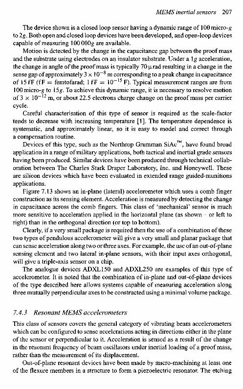
Figure 7.13 shows an in-plane (lateral) accelerometer which uses a comb fingerconstruction as its sensing element. Acceleration is measured by detecting the changein capacitance across the comb fingers. This class of 'mechanical' sensor is muchmore sensitive to acceleration applied in the horizontal plane (as shown - or left toright) than in the orthogonal direction (or top to bottom).
Clearly, if a very small package is required then the use of a combination of thesetwo types of pendulous accelerometer will give a very small and planar package thatcan sense acceleration along two or three axes. For example, the use of an out-of-planesensing element and two lateral in-plane sensors, with their input axes orthogonal,will give a triple-axis sensor on a chip.
The analogue devices ADXLl 50 and ADXL250 are examples of this type ofaccelerometer. It is noted that the combination of in-plane and out-of-plane devicesof the type described here allows systems capable of measuring acceleration alongthree mutually perpendicular axes to be constructed using a minimal volume package.
7.4.3 Resonant MEMS accelerometers
This class of sensors covers the general category of vibrating beam accelerometerswhich can be configured to sense accelerations acting in directions either in the planeof the sensor or perpendicular to it. Acceleration is sensed as a result of the changein the resonant frequency of beam oscillators under inertial loading of a proof mass,rather than the measurement of its displacement.
Out-of-plane resonant devices have been made by micro-machining at least oneof the flexure members in a structure to form a piezoelectric resonator. The etching

TG bias voltage
In-plane accelerometer schematic
Figure 7.13 MEMS lateral in-plane accelerometer (O The Charles Stark DraperLaboratory, Inc. All rights reserved. Reprinted with permission)
of the structure is undertaken at positions where the resonator is calculated to havea zone, or zones, of high stress in its modal pattern. As the flexure element is distortedunder the displacement of the proof mass the resonant frequency of the structurechanges.
Both silicon and quartz devices have been fabricated. Figure 7.14 shows thein-plane (lateral) vibrating beam structure of a silicon oscillating accelerometer (SOA)developed by The Charles Stark Draper Laboratory, Inc. In this case the fundamentalconfiguration is a monolithic vibrating tuning fork structure with a large silicon proofmass, which is driven electrostatically. The beams are loaded axially when an accel-eration is applied in the plane of the vibratory motion (in the plane of the wafer) andthe resonant frequency changes. Oscillator resonance and sensing is accomplishedusing a silicon comb drive structure as shown in the figure.
In-plane accelerometer
Flexure SG- TG- TG+ SG+
Anchor
SG- TG- TG+ SG+
Proof massPosition
AC gainand demod
Servocompensation
Pre-amp
TG rebalancevoltage

Capacitlvely driven resonator Comb drive
Figure 7.14 Silicon oscillating accelerometer (© The Charles Stark Laboratory,Inc. All rights reserved. Reprinted with permission)
The silicon oscillating accelerometer (SOA) MEMS accelerometer manufacturingprocess is silicon on glass; the silicon is perfectly elastic allowing very high precisionfrequency control and stability. The sensor is contained within a ceramic vacuumpackage, which provides high oscillator Q factor (typically > 100 000). For a devicehaving a nominal oscillator frequency of 2OkHz and a scale-factor of 100 Hz/g, afrequency stability of 5 parts per billion yields a bias stability of 1 micro-g.
A device developed in France by ONERA3 is of particular interest. This sensorhas a mechanical isolating system that thermally isolates the vibrating beam from themounting base and protects the sensing element from thermal stress caused by thedifferences in the thermal expansion coefficients of quartz and the case material.This class of accelerometer is capable of inertial-grade performance: accuracy of upto 1 micro-g bias stability has been reported.
7.4.4 Tunnelling MEMS accelerometers
This class of MEMS accelerometers is a recent development that offers significantenhancements over the devices described above that use read-out methods based onmeasurement of changes in capacitance. In this type of accelerometer the read-outhas very high sensitivity and consequently offers better resolution, higher bandwidthand reduced size.
The control electrode deflects the cantilevered beam using an electrostatic forceinto a position known as the tunnelling position, a deflection of less than 1 |xm.The device has a servo system that holds the beam in a position that maintains thegap between the tunnelling tip and the surface of the beam, and thereby maintainsthe tunnelling current, typically of the order of 1 nA. When an acceleration forceis applied it attempts to move the beam and the servo system changes the appliedpotential at the electrode, and this change is a measure of the applied acceleration.A schematic view of this type of sensor is shown in Figure 7.15. The construction uses
3 Office National d'Etudes et de Recherches Aerospatiales.

Figure 7.15 Schematic of a MEMS tunnelling accelerometer (© The CharlesStark Draper Laboratory, Inc. All rights reserved. Reprinted withpermission)
a structure with low resonant frequency proof mass cantilever beams with a mass ofthe order of 1 |xg and read-out circuits with sub-Angstrom resolution.
This class of sensors is designed to have a resolution in the nano-g regime.However, the dynamic range is relatively modest at approximately 106, so themaximum input acceleration is in the 1 milli-g range.
7.4.5 Electrostatically levitated MEMS accelerometers
There have been many diverse studies and developments aimed at removing theconstraints imposed by the elastic restraint and non-linear response of supportingmechanisms. The dynamically tuned gyroscope (Section 4.2.6) and the mass unbal-ance sensor (Section 6.5.4) are two particularly successful devices. However, thesensing element is only free over a very small angle. Novel gyroscopes such as thenuclear magnetic resonance device (Section 4.5.1) and the electrostatically suspendedsensor (Section 4.6) are other examples aimed at very specialised applications.
A new approach involving MEMS technology and electrostatic levitation aimsto produce a high performance accelerometer with high sensitivity, very accurateresolution and an easily adaptable response bandwidth, without modification to thestructure. Additionally, the use of levitation of a small proof mass could ease some ofthe demanding fabrication tolerances. As with all of these novel approaches, there isa shift in the design difficulty and in this case it is to the control loop which becomescomplex. However, with modern computational techniques and electronic systemsthis should not be an insurmountable problem.
This new approach has a small sphere 1 mm diameter with a mass of 1.2 mgsuspended in an electrostatic field. The position of this sphere is sensed by changesin capacitance and a closed loop servo system maintains the position of the sphere by
Cantlleveredproof mass(~1 figm)
Tunnellingtip
Servo control electrode
Output voltage is required to keepcantilevered beam in fixed tunnelling
position during acceleration
A scanning electron microscope (SEM)view of triangular nitride cantilever and
tunnelling tip

Electrode pattern
Figure 7.16 Levitation accelerometer (O The Charles Stark Draper Laboratory,Inc. All rights reserved. Reprinted with permission)
controlling the electrostatic force on the sensing element. A schematic representationof the sensor is shown in Figure 7.16.
The gap between the sphere and the outer shell is formed by removal of a sacrificiallayer of poly crystalline silicon, which is etched through the outer shell structure.
An alternative approach using a levitated disc is under consideration at theUniversity of Southampton in the United Kingdom [H]. This class of technologywith a levitated spinning mass sensing element could lead to a very capable inertialsensor.
This type of sensor is aimed at the measurement of micro-gravity measurementsin space and is expected to have a noise value in the region of 40 micro-g/VHz.
iBiSpliiilii^llljlllllipjIlJIIIilSjil!llilii
Hi
HHHMjBiliililSi
H H H H ^ B
SiO2
Metal
Metal wire
Cross-sectional view of accelerometer(1 mm dia. proof mass)

7.4.6 Dithered accelerometers
There has long been a desire to use a single class of inertial sensor to provide all ofthe inertial measurements for an inertial measurement unit (IMU). Some examplesof approaches that have had some success include:
• use of multiple accelerometers, but this is difficult owing to the real-timeprocessing required;
• use of mass unbalanced tuned rotor gyroscopes, which also requires quite complexprocessing and the sensor package is quite large; see Section 6.5.4;
• use of multi-sensors, which again are not small sensors; see Section 6.5.
A novel technique has been developed from the multi-sensor approach to enableangular rate to be sensed by an accelerometer. In this sensor, the three opposingpairs of monolithic resonating beam accelerometers are dithered about an axis ona vibrating structure. Acceleration applied about the input axes is sensed from thechange in resonant frequency of the vibrating beams in the device. The angularmotion is sensed from synchronous demodulation of the Coriolis force acting on theaccelerometers.
This device has been developed in the form of the micro-machined silicon CoriolisInertial Rate and Acceleration Sensor (ixSCIRAS) [13].
7.5 MOEMS
A new approach to micro-machined sensors is micro-opto electromechanical systems(MOEMS). This class of technology offers a true solid-state sensor with an opti-cal readout, so the limitations in performance of MEMS devices using capacitativetechniques for measuring small displacements are eliminated.
Various optical pick-off techniques are current topics of research. These are eitherinterferometric approaches, which offer low noise and high resolution, or attenuationmethods, involving the interruption of a light beam from a diode. These approaches,or others, may be adapted as the characteristics and origin of the noise are understood,and fully characterised. Another important aspect of an optical read-out is the instal-lation and alignment/harmonisation of the optical source and its detector; particularconsiderations are low-cost installation and maintainability.
7.6 Multi-axis/rotating structures
The approach of mounting in-plane sensors on a rotating ceramic mounting block andusing demodulation techniques to extract the multi-axis inertial data from a reducednumber of sensors, has enabled a considerable size reduction in multi-axis systemsto be achieved. Off-axis sensors may be used for measuring orthogonality.
The use of the more modern in-plane and out-of-plane sensors is likely to lead toa further reduction in IMU size and make the need for a rotating structure redundantfor many applications.

7.7 MEMS based inertial measurement units
A number of projects are underway to produce multi-axis sensors on a chip, whichwill provide estimates of angular rate as well as linear acceleration. Examples includethe combination of two in-plane and one out-of-plane MEMS sensors on a single chip.Such approaches offer many advantages including:
• ease of manufacture;• a vast reduction in volume;• negligible power consumption;• ability to carry out a complete characterisation of the unit in a single operation.
7.7.7 Silicon IMU
The 'Draper' laboratory has reported one chip that has two tuning fork gyroscopesand one out-of plane gyroscope. A complementary chip with three accelerometershas been produced; this integrated sensor also has two in-plane accelerometer sensorsand a single out-of-plane pendulous device. The resulting inertial measurement unithas a volume of about 3.3 cm3 [I]. However, further work is required before a highperformance IMU is available.
BAE Systems has developed a silicon-sensor based IMU for a number of appli-cations [12]. The IMU has three sensing axes, which are in a right-handed orthogonalset. Each sensor axis has an associated set of devices to sense angular rate about thataxis, acceleration along that axis and temperature of the sensors. An exploded viewshowing the layout of the components is shown in Figure 7.17.
This IMU has been designed to operate in an environment that is subjected tohigh angular rates. The inertial sensors are arranged on the edges of a cube to form
Top cover
Processing electronics(compensation and interface)
3 x SiVSG sensor head
3 x Accelerometers
Orthogonal mount
Bottom cover
Yaw axis
Roll axis
Pitch axis
Figure 7.17 SUMU® (Courtesy of BAE Systems)

a right-handed orthogonal set of axes. This axis system is rotated away from thevertical; however, the relative orientations of the sensors with respect to each otherare not skewed. This configuration has the input axes of all sensors at 54.73° to thevertical and is equally spaced at 120° to each other in the horizontal plane.
A direction cosine matrix is used to convert the sensed motion by each of thesensors into a body reference frame. This approach is necessary as no one sensor isaligned with the body axis reference frame in this configuration of sensor axes.
This skew or rotated axis configuration enables
• the x-axis (of the vehicle) to sense up to >/3 times the maximum input angularrate of the gyroscope, when the input rates about the other two orthogonal bodyaxes are zero; similarly for the accelerometer;
• common mode errors, such as sensor bias, to be magnified by y/3 for the x-axis,but reduced for the orthogonal axes.
The downside of this configuration is that if the vehicle containing the IMU issubjected to the same maximum rates simultaneously, then this configuration willrequire sensors with a higher maximum rate capability than would be needed for thenon-rotated cluster.
One of the aspects for achieving high navigational data capability from thesesmall sensors is to undertake characterisation and modelling of the sensors. Thistype of sensor requires equipment that allows application of maximum temperature,acceleration and rates to at least two independent axes. Hence, a single-axis ratetable is inadequate, as scale-factor errors and misalignments need to be observedindependently; therefore dual-axis rate tables are used in the characterisation.
This IMU compensates for the following systematic errors:
• sensor bias;• sensor scale-factor errors;• 'g-dependent' bias of the silicon gyroscopes;• misalignment of axes from harmonisation errors and non-orthogonality;• size effect.
The compensation routine for compensating the above errors runs in real time. Thisleads to a unit with a run-to-run bias of 200°/h (Ia) and 'g'-dependent bias of7°/h/g (lcr). The corresponding performance for the measurement of accelerationis20milli-g(lo).
7.7.2 Quartz IMU
The quartz rate sensor (QRS), described in Section 7.3.2.2, together with a vibratingquartz accelerometer have been built into an IMU; the Systron Donner Digital QuartzIMU (DQI). This is a solid-state, six-degree of freedom inertial measurement sys-tem that provides measurements of angular rate and linear acceleration about threeorthogonal axes [4]. The integrated unit combines the inertial sensor assembly, theinertial sensor assembly electronics and a processor in which digital filtering andcompensation algorithms are implemented.

Figure 7.18 BEIC-MIGITS™ III miniature INS/GPS integrated system (Courtesyof BEI Systron Donner Inertia! Division)
The inertial sensor assembly is machined out of a single aluminium block to forma cube, and is designed to eliminate structural resonances that would coincide withany of the sensor drive modes. To further eliminate coupling between the individualsensors, each sensor operates at a unique drive frequency. One of the advantages ofusing quartz sensors is the stability of this material, which allows each gyroscope tobe produced to a known frequency which can be accurately maintained.
MIGITST is a family of products for applications requiring guidance, navigationand control. The C-MIGITS™ III system, shown in Figure 7.18, is a compact andlightweight system that contains the Systron Donner DQI and a commercial GPSreceiver. The inertial system and GPS measurements are combined using a tightlycoupled integration architecture; discussed separately in Section 13.7.
7.8 System integration
An array of MEMS sensors may be integrated into a single chip to provide multipleindependent measurements of inertial motion. A direct advantage of this class oftechnology is that the sensors may be integrated directly to the electronic controlcircuits, in an applications specific integrated circuit (ASIC) configuration, in a single

hermetically sealed package. The logic control may be achieved by the use of field-programmable gate arrays.
The characteristics of the MEMS devices tend to be of a form that is readilycorrected leading to a sub-system that can be hard mounted in a vehicle. These deviceshave been used in cannon-launched projectiles that experience many thousands of 'g'during the launch of the weapon. The power requirements are modest and compatiblewith normal electronic circuitry.
MEMS devices are ideal for integration with other navigation systems, both interms of complementary error characteristics and small size with rugged operationalcharacteristics.
7.9 Summary
MEMS sensors have developed substantially over the last 15 years in many respects.A number of new approaches have been very successful and this has led to highperformance devices. Advances in the micro-machining techniques have provideda substantial enhancement to the technology, leading to substantial cost reduction.As the technology has advanced there has been a greater understanding of the causeand effects of the error mechanisms and the need for a close integration between thesensing element and the electronic control circuits.
The performance of MEMS devices has increased by many orders of magnitudeover a decade or so, owing to successful development projects. Consequently, MEMSaccelerometers and gyroscopes are capable of providing inertial-grade measurementsof acceleration and angular motion for long-range navigation systems.
Techniques have been demonstrated that enable the sensing devices of an inertialmeasurement unit to be fabricated on a single chip for lower-grade requirements.Methods for characterisation and compensation of systematic errors are proven andhave been applied successfully to a range of systems. However, there is still scopefor further improvement!
There is optimism that further enhancements are possible as a greater under-standing is reached of the effects that geometry, size, packaging and interferencefrom electronic circuits have on the performance of these miniature devices. Itwould be advantageous to improve the turn-on to turn-on repeatability, and reducethe initial transient response particularly for rapid reaction applications. Other per-formance areas where there is scope for improvement include: reduction in noise,improved fabrication precision, improved electronic control and reduced sensitivityto packaging.
The development of MOEMS devices is likely to lead to a further enhancementin performance owing to the true solid-state nature of these devices.
References
1 BARBOUR, N.: 'Inertial navigation sensors', NATO RTO Lecture Series-232,'Advances in Navigation Sensors and Integration Technology', Oct. 2003

2 BARBOUR, N., ANDERSON, R., CONNELLY, J., et al.: 'Inertial MEMS systemapplications', NATO RTO Lecture Series-232, 'Advances in Navigation Sensorsand Integration Technology', Oct. 2003
3 GAIBER, A., FRECH, J., SCHUMACHER, A., et al: 'Evaluation of DAVED -microgyros realised with a new 50|xm SOI-based technology'. Presented atDGON symposium, Gyro Technology', Stuttgart, 2003
4 BAKER, G.: 'Quartz MEMS GPS/INS technology developments'. Presented atDGON symposium, Gyro Technology, Stuttgart, 2003
5 LEGER, P.: 'Quapason-anewlowcost vibratory gyroscope'. Presented at DGONsymposium, Gyro Technology, Stuttgart, 1996
6 ELEY, R., FOX, C.H.J., and McWILLIAM, S.: 'The dynamics of a vibrating-ringmulti-axis rate gyroscope', Proc. Institution of Mechanical Engineers, 2000,214,Part C
7 ROURKE, A.K., FOX, C.H.J., and McWILLIAM, S.: 'Development and testingof novel, multi-channel vibrating structure rate sensor'. Presented at DGONsymposium, Gyro Technology, Stuttgart, 2003
8 FOX, C.H.J., ROURKE, A.K., ELEY, R., FELL, C , and McWILLIAM, S.,'Multi-channel and multi-axis inertial sensor concepts based on vibratingstructures'. Presented at SPIE conference, Smart Structures and Materials,San Diego, CA, March 2003
9 ROYLE, CM., and FOX, C.H.J.: 'The mechanics of an oscillatory rate gyroscopewith piezoelectric film actuation and sensing', Proc. Institution of MechanicalEngineers, 2001, 215, Part C
10 FOUNTAIN, J.R.: 'Characteristics and overview of a silicon vibrating structuregyroscope', NATO RTO Lecture Series-232, 'Advances in Navigation Sensorsand Integration Technology', Oct. 2003
11 HOULIHAN, R.: 'Modelling of an accelerometer based on a levitated proof mass',Journal of Micromechanics and Microengineering, 1992,13 (4), pp. 495-503
12 FOUNTAIN, J.R.: 'Silicon IMU for missile and munitions applications',NATO RTO Lecture Series-232, 'Advances in Navigation Sensors and IntegrationTechnology', Oct. 2003
13 HULSING, R.: 'MEMS Inertial rate and acceleration sensor,' ION NationalTechnical Meeting, CA, January, 1998