menara customer gui - menara...
TRANSCRIPT

Menara Networks 020-04007-00E
March 2013 CONFIDENTIAL & PROPRIETARY 1
Menara Customer GUI
User Manual
Menara Networks 020-04007-00E
March 2013 CONFIDENTIAL & PROPRIETARY 2
Table of Contents 1. Introduction ........................................................................................................................................... 4
1.1. Equipment List ............................................................................................................................. 4 1.1.1. Host Board Equipment List ................................................................................................. 4 1.1.2. USB Tuning Cable Equipment List ..................................................................................... 4
1.2. Menara GUI Installation ............................................................................................................... 5 1.3. Installing Menara USB Tuning Cable Driver (SFP+ or XFP) ....................................................... 5 1.4. Connecting to the RS-232 Host Board ...................................................................................... 10 1.5. Launching the Customer GUI .................................................................................................... 10
2. SFP/SFP+ Tuning Cable .................................................................................................................... 12 2.1. SFP+ Wavelength Tuning .......................................................................................................... 12 2.2. Alarms and Status ..................................................................................................................... 13
3. XFP Tuning Cable and Serial Host Board .......................................................................................... 15 3.1. XFP Wavelength Tuning ............................................................................................................ 16 3.2. Default Traffic Mode Setting ...................................................................................................... 21 3.3. BER Test – Available on Host Board ONLY .............................................................................. 24
3.3.1. Test Topology ................................................................................................................... 24 3.3.2. Test Procedure .................................................................................................................. 24 3.3.3. Operating the Quick BER Test .......................................................................................... 27 3.3.4. Wavelength Tuning ........................................................................................................... 31 3.3.5. Save the Test Data ........................................................................................................... 31
3.4. Set Payload Type Identifier........................................................................................................ 32 3.5. Tuning by Wavelegth ................................................................................................................. 35
Appendix A: Menara Wavelength Reference Table .................................................................................... 37 Appendix B: Saved Data File ...................................................................................................................... 39 Appendix C: Troubleshooting ...................................................................................................................... 41

Menara Networks 020-04007-00E
March 2013 CONFIDENTIAL & PROPRIETARY 3
Table of Figures Figure 1: Menara Customer GUI ................................................................................................................. 10 Figure 2: SFP+ Wavelength Tuning ............................................................................................................ 12 Figure 3: SFP Alarms & Status ................................................................................................................... 13 Figure 4: SFP/SFP+ Alarms & Status ......................................................................................................... 14 Figure 5: XFP Tuning Cable Applications ................................................................................................... 15 Figure 6: XFP Serial Host board applications ............................................................................................. 16 Figure 7: WL Tuning GUI ............................................................................................................................ 17 Figure 8: Wavelength Tuning GUI – Current Channel ................................................................................ 18 Figure 9: Wavelength Tuning GUI - Channel Select ................................................................................... 19 Figure 10: Wavelength Tuning GUI – Successful change of the part number and wavelength ................. 19 Figure 11: Traffic Mode Setting GUI – Analyze XFP .................................................................................. 21 Figure 12: Traffic Mode Setting GUI – Set Default Traffic from PassThru to OTN Mode ........................... 22 Figure 13: Traffic was Successfully Converted from PassThru to OTN mode. .......................................... 23 Figure 14: Quick BER GUI - Initializing ....................................................................................................... 25 Figure 15: Pre-FEC BER Test..................................................................................................................... 28 Figure 16: Pre-FEC and Post-FEC BER Test ............................................................................................. 29 Figure 17: Post-FEC BER Test with FEC Set to Off. .................................................................................. 30 Figure 18: Pre-FEC and Post-FEC BER Test with High BER .................................................................... 31 Figure 19: Set PTI GUI ................................................................................................................................ 32 Figure 20: Setting the PTI Value ................................................................................................................. 32 Figure 21: Set PTI Success ........................................................................................................................ 34 Figure 22: Tuning by Wavelength ............................................................................................................... 35 Figure 23: Tuning by Wavelength Complete ............................................................................................... 36

Menara Networks 020-04007-00E
March 2013 CONFIDENTIAL & PROPRIETARY 4
1. Introduction
This document describes the Menara GUI which allows a user to perform the following tasks:
Read and modify the wavelength of the Menara tunable XFP and SFP+ modules
Read and switch the default traffic mode between OTN and PassThru on Menara OTN XFPs
Read and switch the TX Payload Type Identifier (PTI) on Menara OTN XFPs
Run link performance testing with 231
-1 PRBS payload over a DWDM network (Menara Host
Board only)
Disable the tuning by wavelength option on Menara OTN XFPs
These tasks can be performed using the Menara serial host board (XFP only) or USB tuning cables.
Procedures for installing the driver files for the USB tuning cables will also be covered in this document.
1.1. Equipment List
The following section describes the equipment needed to connect to either the Host Board or the USB Tuning cables.
1.1.1. Host Board Equipment List
1. 1 - OTN XFP RS-232 Host Board
2. 1 - PC with Menara GUI software installed – version 1.15 or later
3. 1 – Standard RS-232 cable (straight) or RS-232 to USB cable if the computer does not have an
RS-232 com port
4. 1 – 12V wall mount AC adaptor
5. 1 - OTN XFP Module
Note: In order to test the OTN XFPs over a DWDM network then the equipment list above should be
doubled plus the below are required:
6. 4 – LC-LC 2-meter optical patch cords
7. 2 – Fixed 10dB to 20dB attenuators
1.1.2. USB Tuning Cable Equipment List
1. 1 – Menara USB Tuning unit (SFP+ or XFP)
2. 1 - PC with Menara GUI software installed – version 1.15 or later
3. 1 – USB2.0 A-Male to USB B-Male cable
4. 1 – Tunable XFP or SFP+ module
Menara Networks 020-04007-00E
March 2013 CONFIDENTIAL & PROPRIETARY 5
1.2. Menara GUI Installation
1. If an existing copy of the Menara OTN XFP GUI is installed it will be necessary to uninstall the
existing version GUI before installing a newer version. Please follow the directions below if required.
a. Open the Control Panel and then select uninstall programs b. Select the OTN XFP GUI software and press uninstall.
2. Download version 1.15 or later of the Menara Customer GUI from http://www.menaranet.com/GUI/
3. Unzip and copy all files to a local folder. 4. Double click on setup.exe file inside the Menara Customer GUI installer folder to install the GUI.
Follow the step by step instruction and once the installation is completed, a ‘Menara Customer GUI” icon should appear on the desk top.
5. Click on the icon to launch the GUI.
1.3. Installing Menara USB Tuning Cable Driver (SFP+ or XFP)
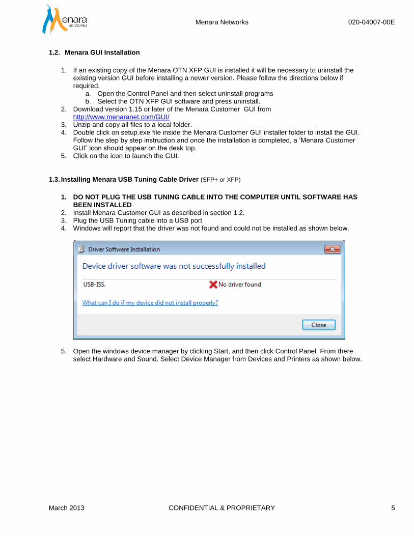
1. DO NOT PLUG THE USB TUNING CABLE INTO THE COMPUTER UNTIL SOFTWARE HAS
BEEN INSTALLED 2. Install Menara Customer GUI as described in section 1.2. 3. Plug the USB Tuning cable into a USB port 4. Windows will report that the driver was not found and could not be installed as shown below.
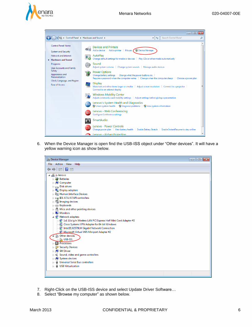
5. Open the windows device manager by clicking Start, and then click Control Panel. From there select Hardware and Sound. Select Device Manager from Devices and Printers as shown below.
Menara Networks 020-04007-00E
March 2013 CONFIDENTIAL & PROPRIETARY 6
6. When the Device Manager is open find the USB-ISS object under “Other devices”. It will have a yellow warning icon as show below.
7. Right-Click on the USB-ISS device and select Update Driver Software… 8. Select “Browse my computer” as shown below.
Menara Networks 020-04007-00E
March 2013 CONFIDENTIAL & PROPRIETARY 7
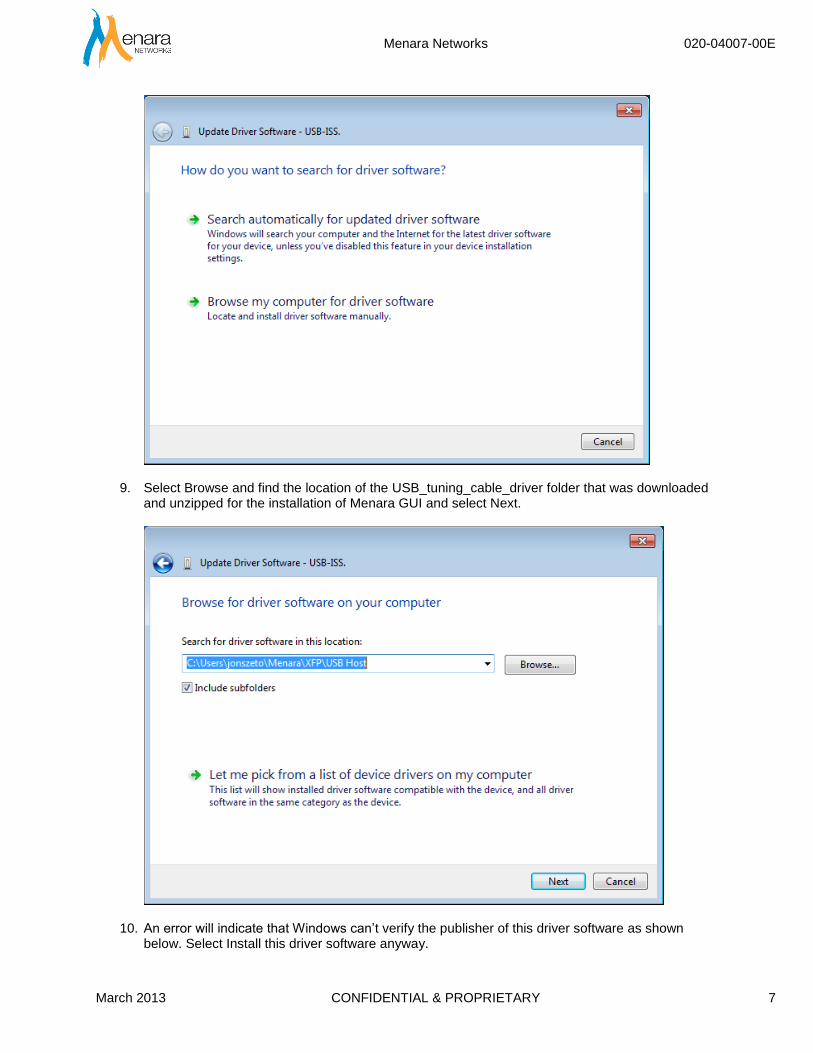
9. Select Browse and find the location of the USB_tuning_cable_driver folder that was downloaded and unzipped for the installation of Menara GUI and select Next.
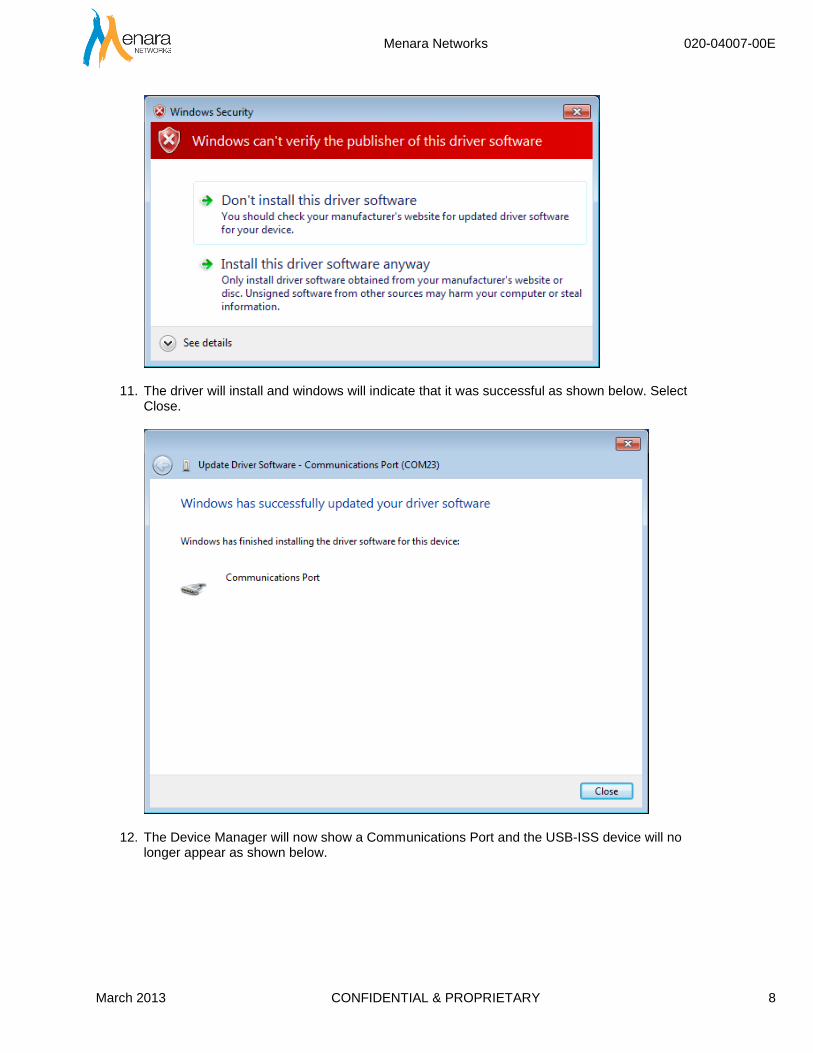
10. An error will indicate that Windows can’t verify the publisher of this driver software as shown below. Select Install this driver software anyway.
Menara Networks 020-04007-00E
March 2013 CONFIDENTIAL & PROPRIETARY 8
11. The driver will install and windows will indicate that it was successful as shown below. Select Close.
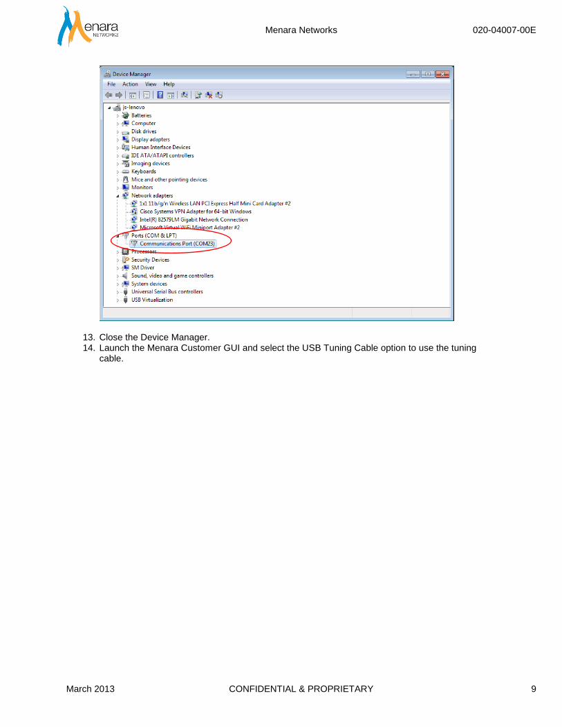
12. The Device Manager will now show a Communications Port and the USB-ISS device will no longer appear as shown below.
Menara Networks 020-04007-00E
March 2013 CONFIDENTIAL & PROPRIETARY 9
13. Close the Device Manager. 14. Launch the Menara Customer GUI and select the USB Tuning Cable option to use the tuning
cable.

Menara Networks 020-04007-00E
March 2013 CONFIDENTIAL & PROPRIETARY 10
1.4. Connecting to the RS-232 Host Board
The following procedure describes how to connect to a RS-232 Serial host board.
1. Connect the host board serial com port to the computer serial com port (or USB port if a RS-
232/USB converter cable is used.)
a. Install the RS-232 to USB drivers that came with the host board if necessary
2. Connect the 12V DC input to the host board
3. Double click on Menara Customer GUI icon to launch the GUI.
1.5. Launching the Customer GUI
The following procedure describes how to start the Customer GUI.
1. Double-Click on the Menara Customer GUI Icon
A menu will appear as shown in Figure 1 below.
Figure 1: Menara Customer GUI
2. There will be three options to choose. Ensure that the proper device is plugged into the PC.

Menara Networks 020-04007-00E
March 2013 CONFIDENTIAL & PROPRIETARY 11
a. Tuning Cable SFP/SFP+ – This GUI is for the tunable SFP+ modules only
b. Tuning Cable OTN XFP GUI – This GUI is for the Menara OTN XFP modules and the
USB tuning cable
c. Serial Host board OTN XFP GUI – This GUI is for Menara OTN XFP modules and the
serial host board.
3. Select the desired program to launch. Details for the programs are found later in this manual.
Menara Networks 020-04007-00E
March 2013 CONFIDENTIAL & PROPRIETARY 12
2. SFP/SFP+ Tuning Cable
The GUI for the SFP/SFP+ is designed to be used with the Menara Tunable SFP+ modules or Menara non-tunable modules. However, some features are only available with the Menara Tunable SFP+ module.
2.1. SFP+ Wavelength Tuning
SFP+ Wavelength tuning can only be done with the Menara Tunable SFP+. The following procedure can be used to change the wavelength of the Menara tunable SFP+ module.
1. Insert the tunable SFP+ module in the tuning cable and insert the tuning cable into an open USB port.
2. Launch the Menara Customer GUI and the SFP/SFP+ GUI
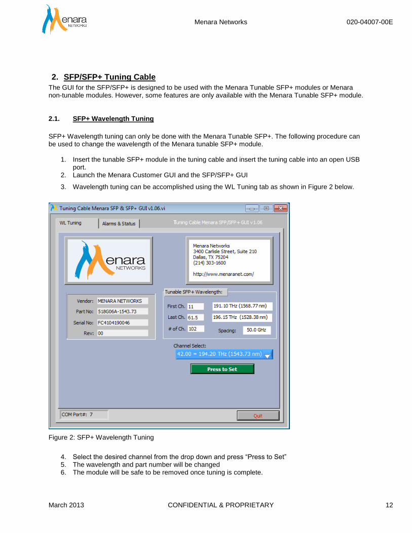
3. Wavelength tuning can be accomplished using the WL Tuning tab as shown in Figure 2 below.
Figure 2: SFP+ Wavelength Tuning
4. Select the desired channel from the drop down and press “Press to Set” 5. The wavelength and part number will be changed 6. The module will be safe to be removed once tuning is complete.
Menara Networks 020-04007-00E
March 2013 CONFIDENTIAL & PROPRIETARY 13
2.2. Alarms and Status
This section of the SFP/SFP+ GUI can be used for diagnostic testing and monitoring of alarms. It does not generate any customer traffic.
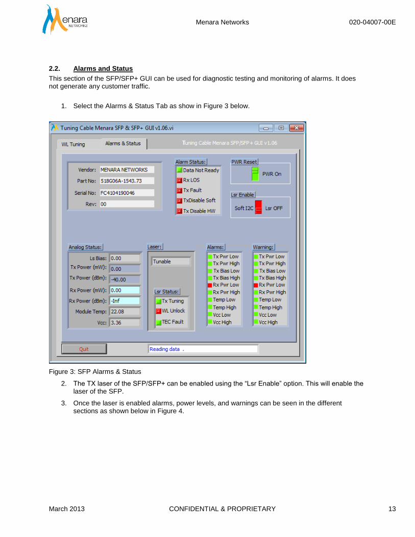
1. Select the Alarms & Status Tab as show in Figure 3 below.
Figure 3: SFP Alarms & Status
2. The TX laser of the SFP/SFP+ can be enabled using the “Lsr Enable” option. This will enable the laser of the SFP.
3. Once the laser is enabled alarms, power levels, and warnings can be seen in the different sections as shown below in Figure 4.

Menara Networks 020-04007-00E
March 2013 CONFIDENTIAL & PROPRIETARY 14
Figure 4: SFP/SFP+ Alarms & Status
4. The module can also be reset using the PWR Reset option
5. Press “Quit” to exit the GUI

Menara Networks 020-04007-00E
March 2013 CONFIDENTIAL & PROPRIETARY 15
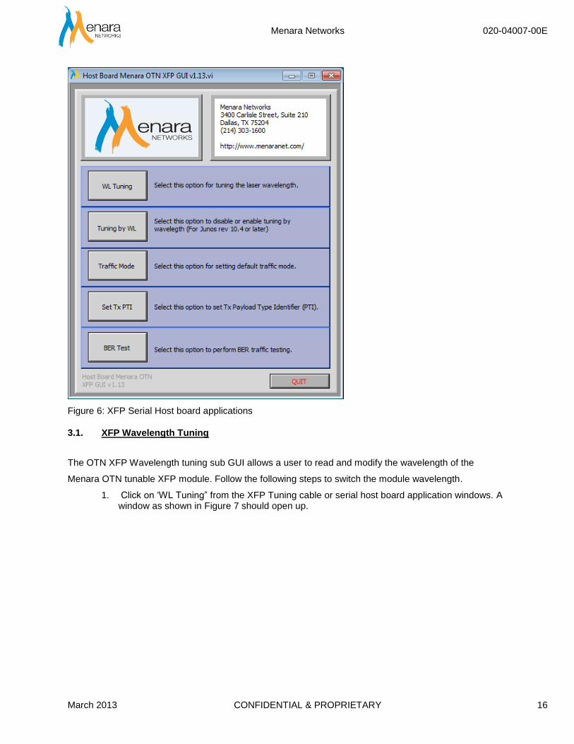
3. XFP Tuning Cable and Serial Host Board
The following applications can be found using the XFP Tuning cable or the serial host board. These require the use of Menara OTN XFPs. The options for the USB Tuning cable are show in Figure 5 and the Serial Host board in Figure 6.
Figure 5: XFP Tuning Cable Applications
Menara Networks 020-04007-00E
March 2013 CONFIDENTIAL & PROPRIETARY 16
Figure 6: XFP Serial Host board applications
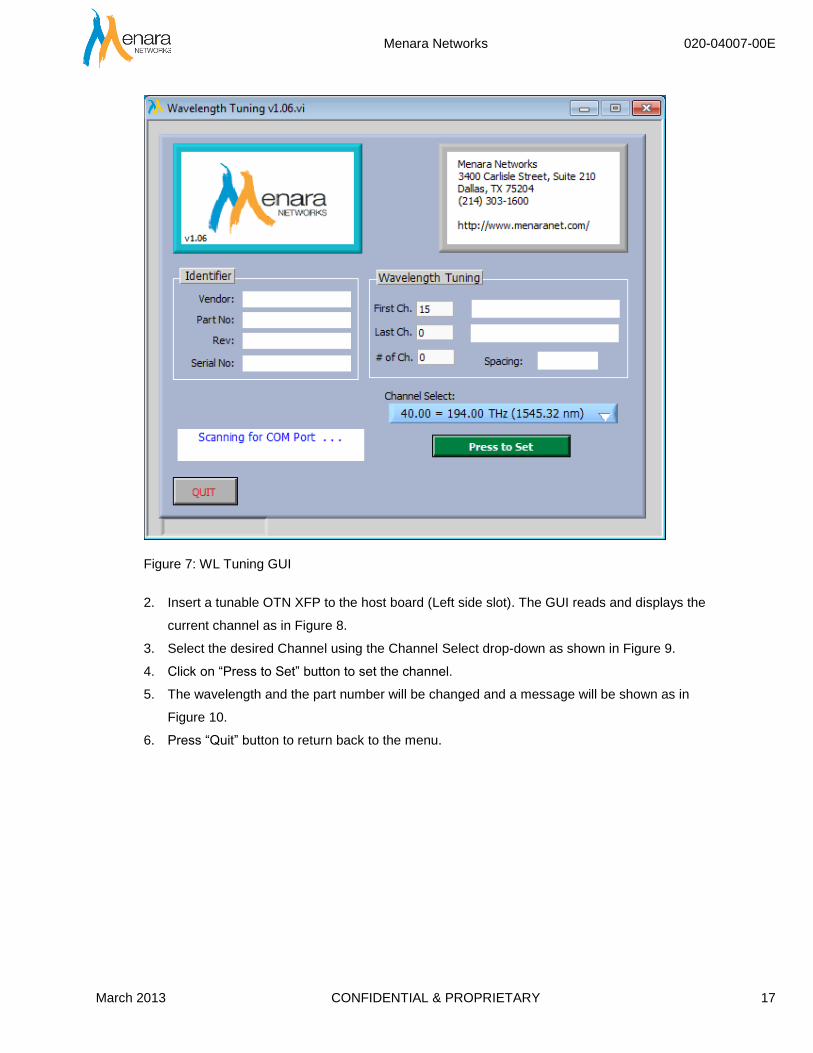
3.1. XFP Wavelength Tuning
The OTN XFP Wavelength tuning sub GUI allows a user to read and modify the wavelength of the
Menara OTN tunable XFP module. Follow the following steps to switch the module wavelength.
1. Click on ‘WL Tuning” from the XFP Tuning cable or serial host board application windows. A window as shown in Figure 7 should open up.
Menara Networks 020-04007-00E
March 2013 CONFIDENTIAL & PROPRIETARY 17
Figure 7: WL Tuning GUI
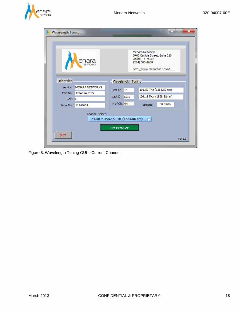
2. Insert a tunable OTN XFP to the host board (Left side slot). The GUI reads and displays the
current channel as in Figure 8.
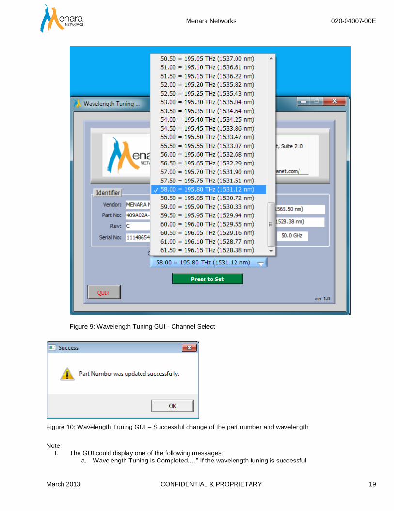
3. Select the desired Channel using the Channel Select drop-down as shown in Figure 9.
4. Click on “Press to Set” button to set the channel.
5. The wavelength and the part number will be changed and a message will be shown as in
Figure 10.
6. Press “Quit” button to return back to the menu.
Menara Networks 020-04007-00E
March 2013 CONFIDENTIAL & PROPRIETARY 18
Figure 8: Wavelength Tuning GUI – Current Channel
Menara Networks 020-04007-00E
March 2013 CONFIDENTIAL & PROPRIETARY 19
Figure 9: Wavelength Tuning GUI - Channel Select
Figure 10: Wavelength Tuning GUI – Successful change of the part number and wavelength
Note:
I. The GUI could display one of the following messages: a. Wavelength Tuning is Completed,…” If the wavelength tuning is successful

Menara Networks 020-04007-00E
March 2013 CONFIDENTIAL & PROPRIETARY 20
b. “No new wavelength was selected …” if “Press to Set” button was pressed without selecting a new channel to tune to.
II. Follow the same procedure to tune a 2-channel OTN XFP.

Menara Networks 020-04007-00E
March 2013 CONFIDENTIAL & PROPRIETARY 21
3.2. Default Traffic Mode Setting
The OTN XFP supports traffic in either PassThru or OTN G.709 mode. The default “Traffic Mode Setting” sub GUI allows a user to program the traffic mode in which the module we come up in after power up. Follow the following steps to set the default traffic mode:
1. Click ‘Traffic Mode” button from the “Menara OTN XFP GUI”. 2. Enter a proper IP address (Network Mode only) and then press enter. If there is an OTN XFP
module already in the left slot, the GUI will start to analyze the XFP to determine if it is compatible for default traffic mode switching and the current traffic mode as shown in Figure 11. The “XFP Analyzer” checks part number and the FW version to determine if the module supports default traffic mode switching or not. If it does not support traffic mode switching, then the user has to return the module back to Menara to set the new default traffic mode.
Figure 11: Traffic Mode Setting GUI – Analyze XFP
Menara Networks 020-04007-00E
March 2013 CONFIDENTIAL & PROPRIETARY 22
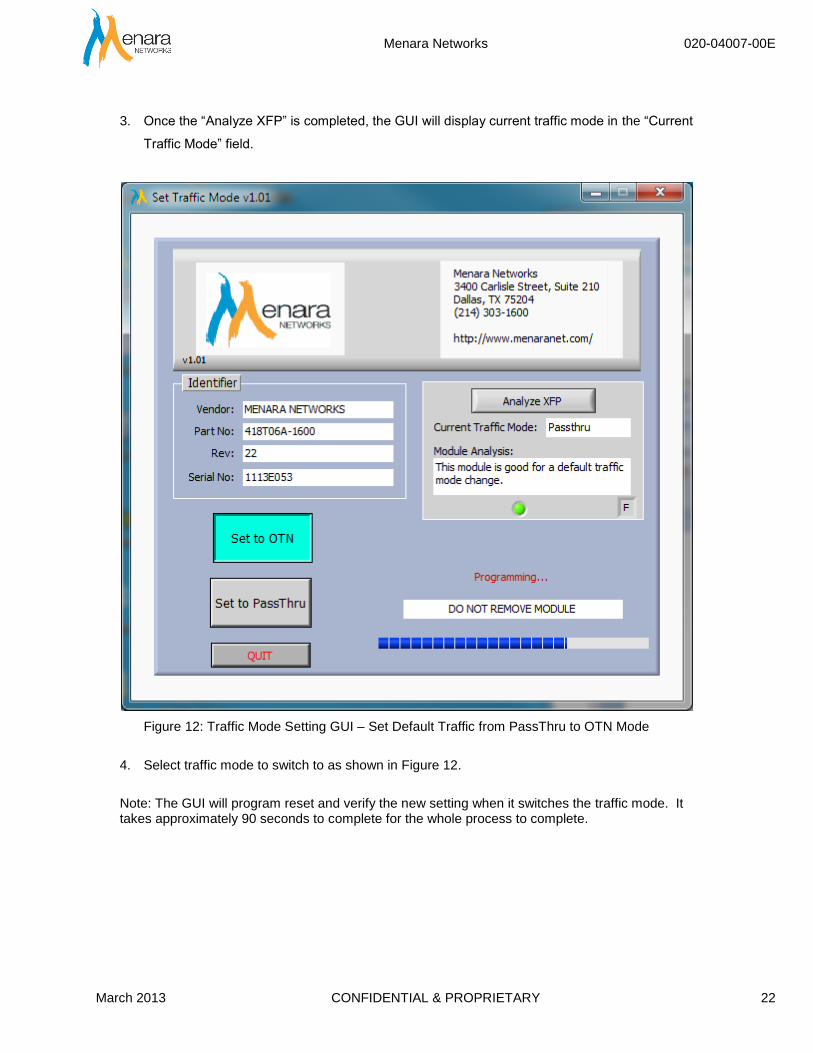
3. Once the “Analyze XFP” is completed, the GUI will display current traffic mode in the “Current
Traffic Mode” field.
Figure 12: Traffic Mode Setting GUI – Set Default Traffic from PassThru to OTN Mode
4. Select traffic mode to switch to as shown in Figure 12.
Note: The GUI will program reset and verify the new setting when it switches the traffic mode. It takes approximately 90 seconds to complete for the whole process to complete.
Menara Networks 020-04007-00E
March 2013 CONFIDENTIAL & PROPRIETARY 23
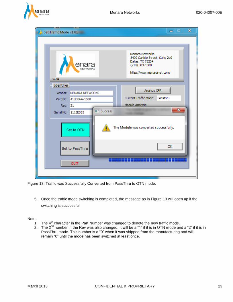
Figure 13: Traffic was Successfully Converted from PassThru to OTN mode.
5. Once the traffic mode switching is completed, the message as in Figure 13 will open up if the
switching is successful.
Note: 1. The 4
th character in the Part Number was changed to denote the new traffic mode.
2. The 2nd
number in the Rev was also changed. It will be a “1” if it is in OTN mode and a “2” if it is in PassThru mode. This number is a “0” when it was shipped from the manufacturing and will remain “0” until the mode has been switched at least once.

Menara Networks 020-04007-00E
March 2013 CONFIDENTIAL & PROPRIETARY 24
3.3. BER Test – Available on Host Board ONLY
The OTN XFP BER Test sub GUI allows a user to measure and run BER test over a DWDM network or just back to back to verify the XFP performance as incoming inspection or at any other time. The test results can be saved as a text file for benchmarking or reference.
3.3.1. Test Topology
The BER Test can be run in one of two ways. It can either be run head to head using two host boards running the Quick BER test, from a single host board to a facility loop on a third party router, or another device with second Menara XFP installed.
3.3.2. Test Procedure
1) From the “Menara OTN XFP GUI” window, select “BER Test” button to launch the GUI.
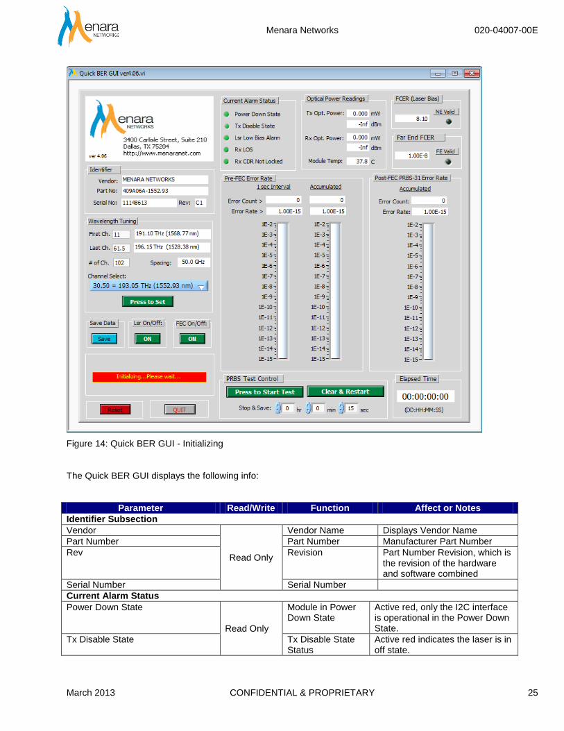
2) Enter a valid IP address (Network GUI only). If there is no module in the slot, “No module detected. Insert a module” message will be flashing. Otherwise the GUI will start to initialize the module as shown in Figure 14.
Note: If an invalid COM port number or IP address is entered, then an error message window as in Error! Reference source not found. or Error! Reference source not found. will appear. Enter the correct IP address or COM port to proceed.
Menara Networks 020-04007-00E
March 2013 CONFIDENTIAL & PROPRIETARY 25
Figure 14: Quick BER GUI - Initializing
The Quick BER GUI displays the following info:
Parameter Read/Write Function Affect or Notes
Identifier Subsection
Vendor
Read Only
Vendor Name Displays Vendor Name
Part Number Part Number Manufacturer Part Number
Rev Revision Part Number Revision, which is the revision of the hardware and software combined
Serial Number Serial Number
Current Alarm Status
Power Down State
Read Only
Module in Power Down State
Active red, only the I2C interface is operational in the Power Down State.
Tx Disable State Tx Disable State Status
Active red indicates the laser is in off state.
Menara Networks 020-04007-00E
March 2013 CONFIDENTIAL & PROPRIETARY 26
Parameter Read/Write Function Affect or Notes
Lsr Low Bias Warning Laser Low Bias Warning Status.
Active red, indicated laser bias is fall below the Low Bias Warning threshold. When the laser bias current displays the FCER, the Warning alarm displays the Pre-FEC error alarm. The Pre-FEC alarm threshold is normally set to 1E-5.
Rx LOS Rx LOS Status Active red indicates loss of signal on the Rx input.
Rx CDR Not Locked Rx CDR Not Locked Status
Active red, indicates the Rx CDR, is not locked.
Optical Power Range
Tx Opt. Power
Read Only
Tx Output Power Tx output power in dBm and mW.
Rx Opt. Power Rx Input Power Rx input power in dBm and mW.
Module Temp Module Temperature
Module case temperature in Celsius.
FCER Counters
FCER (Laser Bias)
Read only
NE FCER Near End FCER
NE Valid (ity flag) NE Validity Flag indicator
The NE FCER is valid when FE validity flag is green
Far End FCER Far End FCER Far End FCER
FE Valid (ity Flag) FE Validity Flag indicator
The FE FCER is valid when FE validity flag is green
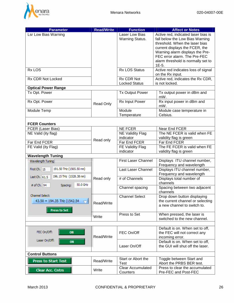
Wavelength Tuning
Read only
First Laser Channel Displays ITU channel number, Frequency and wavelength
Last Laser Channel Displays ITU channel number, Frequency and wavelength
# of Channels
Displays total number of channels
Channel spacing Spacing between two adjacent channels
Read/Write
Channel Select
Drop down button displaying the current channel or selecting a new channel to switch to.
Write Press to Set When pressed, the laser is
switched to the new channel.
Read/Write
FEC On/Off
Default is on. When set to off, the FEC will not correct any incoming error.
Laser On/Off
Default is on. When set to off, the GUI will shut off the laser.
Control Buttons
Read/Write
Start or Abort the Test
Toggle between Start and Abort the PRBS BER test.
Write
Clear Accumulated Counters
Press to clear the accumulated Pre-FEC and Post-FEC

Menara Networks 020-04007-00E
March 2013 CONFIDENTIAL & PROPRIETARY 27
Parameter Read/Write Function Affect or Notes
counters.
Read/Write
Elapsed Time of the Current Running Test
Indicates the current test elapse time. Only counting when the PRBS BER test is running.
Write
Stop and Save Time The default test time is 1hr. Enter a new number to set the test time. The test will stop once the elapse time reaches Stop & Save time. The user is prompted to enter a file name where the data is to be saved to.
Write
Save the current test data.
When pressed, the user is prompted to enter a file name where the test data is to be saved to. The test will be stopped at that point.
Write
Quit or terminate the BER Test GUI
When pressed, the BER Test sub GUI is stopped returned to the Menara OTN XFO GUI.
Write
Reset
When pressed, the GUI re-initialized the module. Only selectable when the PRBS BER is not running.
3.3.3. Operating the Quick BER Test
The GUI will start to initialize the module when a new module is inserted or when the GUI is launched and there is a module in the slot. The Pre-FEC BER test will start automatically once the module initialization was completed.
Menara Networks 020-04007-00E
March 2013 CONFIDENTIAL & PROPRIETARY 28
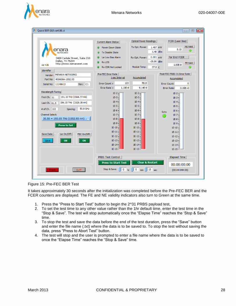
Figure 15: Pre-FEC BER Test
It takes approximately 30 seconds after the initialization was completed before the Pre-FEC BER and the FCER counters are displayed. The FE and NE validity indicators also turn to Green at the same time.
1. Press the “Press to Start Test” button to begin the 2^31 PRBS payload test, 2. To set the test time to any other value rather than the 1hr default time, enter the test time in the
“Stop & Save”. The test will stop automatically once the “Elapse Time” reaches the ‘Stop & Save” time.
3. To stop the test and save the data before the end of the test duration, press the “Save” button and enter the file name (.txt) where the data is to be saved to. To stop the test without saving the data, press “Press to Abort Test” button.
4. The test will stop and the user is prompted to enter a file name where the data is to be saved to once the “Elapse Time” reaches the “Stop & Save” time.

Menara Networks 020-04007-00E
March 2013 CONFIDENTIAL & PROPRIETARY 29
Figure 16: Pre-FEC and Post-FEC BER Test
Note: Tx output is looped back to the Rx input through an optical attenuator. In this set up, the Near End and Far End FCER counters displays the same value.
Menara Networks 020-04007-00E
March 2013 CONFIDENTIAL & PROPRIETARY 30
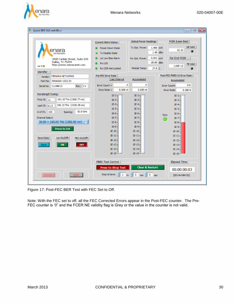
Figure 17: Post-FEC BER Test with FEC Set to Off.
Note: With the FEC set to off, all the FEC Corrected Errors appear in the Post-FEC counter. The Pre-FEC counter is ‘0” and the FCER NE validity flag is Grey or the value in the counter is not valid.

Menara Networks 020-04007-00E
March 2013 CONFIDENTIAL & PROPRIETARY 31
Figure 18: Pre-FEC and Post-FEC BER Test with High BER
Note: With very low input power, at -32.22dBm, the FEC could not correct all the errors in the incoming data. Any error that is not corrected is appeared in the Post-FEC counter.
3.3.4. Wavelength Tuning
The Wavelength Tuning procedure is exactly the same as described above.
3.3.5. Save the Test Data
When the “Elapsed Time” reaches the “Stop & Save” time, or when the “Save” button is pressed, the user is prompted to enter a file name where the data is to be saved to. Enter a file name and .txt as file type. If an existing file name is entered, the GUI will append the data to the existing data in that file. The content of the saved data is displayed in Appendix B.
Menara Networks 020-04007-00E
March 2013 CONFIDENTIAL & PROPRIETARY 32
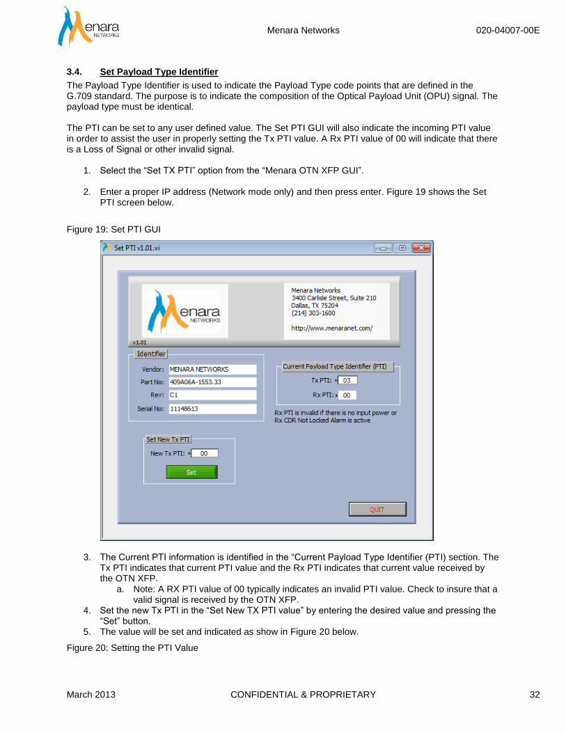
3.4. Set Payload Type Identifier
The Payload Type Identifier is used to indicate the Payload Type code points that are defined in the G.709 standard. The purpose is to indicate the composition of the Optical Payload Unit (OPU) signal. The payload type must be identical. The PTI can be set to any user defined value. The Set PTI GUI will also indicate the incoming PTI value in order to assist the user in properly setting the Tx PTI value. A Rx PTI value of 00 will indicate that there is a Loss of Signal or other invalid signal.
1. Select the “Set TX PTI” option from the “Menara OTN XFP GUI”. 2. Enter a proper IP address (Network mode only) and then press enter. Figure 19 shows the Set
PTI screen below.
Figure 19: Set PTI GUI
3. The Current PTI information is identified in the “Current Payload Type Identifier (PTI) section. The Tx PTI indicates that current PTI value and the Rx PTI indicates that current value received by the OTN XFP.
a. Note: A RX PTI value of 00 typically indicates an invalid PTI value. Check to insure that a valid signal is received by the OTN XFP.
4. Set the new Tx PTI in the “Set New TX PTI value” by entering the desired value and pressing the “Set” button.
5. The value will be set and indicated as show in Figure 20 below.
Figure 20: Setting the PTI Value

Menara Networks 020-04007-00E
March 2013 CONFIDENTIAL & PROPRIETARY 33
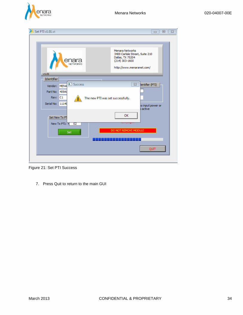
6. A successful completion will be show in Figure 21 below.
Menara Networks 020-04007-00E
March 2013 CONFIDENTIAL & PROPRIETARY 34
Figure 21: Set PTI Success
7. Press Quit to return to the main GUI
Menara Networks 020-04007-00E
March 2013 CONFIDENTIAL & PROPRIETARY 35
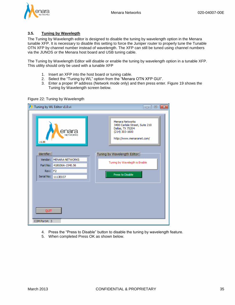
3.5. Tuning by Wavelegth
The Tuning by Wavelength editor is designed to disable the tuning by wavelength option in the Menara tunable XFP. It is necessary to disable this setting to force the Juniper router to properly tune the Tunable OTN XFP by channel number instead of wavelength. The XFP can still be tuned using channel numbers via the JUNOS or the Menara host board and USB tuning cable. The Tuning by Wavelength Editor will disable or enable the tuning by wavelength option in a tunable XFP. This utility should only be used with a tunable XFP
1. Insert an XFP into the host board or tuning cable. 2. Select the “Tuning by WL” option from the “Menara OTN XFP GUI”. 3. Enter a proper IP address (Network mode only) and then press enter. Figure 19 shows the
Tuning by Wavelength screen below.
Figure 22: Tuning by Wavelength
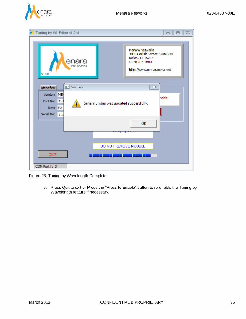
4. Press the “Press to Disable” button to disable the tuning by wavelength feature. 5. When completed Press OK as shown below.
Menara Networks 020-04007-00E
March 2013 CONFIDENTIAL & PROPRIETARY 36
Figure 23: Tuning by Wavelength Complete
6. Press Quit to exit or Press the “Press to Enable” button to re-enable the Tuning by
Wavelength feature if necessary.

Menara Networks 020-04007-00E
March 2013 CONFIDENTIAL & PROPRIETARY 37
Appendix A: Menara Wavelength Reference Table The following table provides correlation of the ITU-T DWDM wavelength and frequency as it relates to Menara Networks ID.
Frequency Wavelength Menara ID
196.15 1528.38 61.5
196.10 1528.77 61
196.05 1529.16 60.5
196.00 1529.55 60
195.95 1529.94 59.5
195.90 1530.33 59
195.85 1530.72 58.5
195.80 1531.12 58
195.75 1531.51 57.5
195.70 1531.90 57
195.65 1532.29 56.5
195.60 1532.68 56
195.55 1533.07 55.5
195.50 1533.47 55
195.45 1533.86 54.5
195.40 1534.25 54
195.35 1534.64 53.5
195.30 1535.04 53
195.25 1535.43 52.5
195.20 1535.82 52
195.15 1536.22 51.5
195.10 1536.61 51
195.05 1537.00 50.5
195.00 1537.40 50
194.95 1537.79 49.5
194.90 1538.19 49
194.85 1538.58 48.5
194.80 1538.98 48
194.75 1539.37 47.5
194.70 1539.77 47
194.65 1540.16 46.5
194.60 1540.56 46
194.55 1540.95 45.5
194.50 1541.35 45
194.45 1541.75 44.5
194.40 1542.14 44
194.35 1542.54 43.5
194.30 1542.94 43
194.25 1543.33 42.5
194.20 1543.73 42
194.15 1544.13 41.5
194.10 1544.53 41
194.05 1544.92 40.5
194.00 1545.32 40
Frequency Wavelength Menara ID
193.95 1545.72 39.5
193.90 1546.12 39
193.85 1546.52 38.5
193.80 1546.92 38
193.75 1547.32 37.5
193.70 1547.72 37
193.65 1548.11 36.5
193.60 1548.51 36
193.55 1548.91 35.5
193.50 1549.32 35
193.45 1549.72 34.5
193.40 1550.12 34
193.35 1550.52 33.5
193.30 1550.92 33
193.25 1551.32 32.5
193.20 1551.72 32
193.15 1552.12 31.5
193.10 1552.52 31
193.05 1552.93 30.5
193.00 1553.33 30
192.95 1553.73 29.5
192.90 1554.13 29
192.85 1554.54 28.5
192.80 1554.94 28
192.75 1555.34 27.5
192.70 1555.75 27
192.65 1556.15 26.5
192.60 1556.55 26
192.55 1556.96 25.5
192.50 1557.36 25
192.45 1557.77 24.5
192.40 1558.17 24
192.35 1558.58 23.5
192.30 1558.98 23
192.25 1559.39 22.5
192.20 1559.79 22
192.15 1560.20 21.5
192.10 1560.61 21
192.05 1561.01 20.5
192.00 1561.42 20
191.95 1561.83 19.5
191.90 1562.23 19
191.85 1562.64 18.5
191.80 1563.05 18

Menara Networks 020-04007-00E
March 2013 CONFIDENTIAL & PROPRIETARY 38
Frequency Wavelength Menara ID
191.75 1563.45 17.5
191.70 1563.86 17
191.65 1564.27 16.5
Frequency Wavelength Menara ID
191.60 1564.68 16
191.55 1565.09 15.5
191.50 1565.50 15

Menara Networks 020-04007-00E
March 2013 CONFIDENTIAL & PROPRIETARY 39
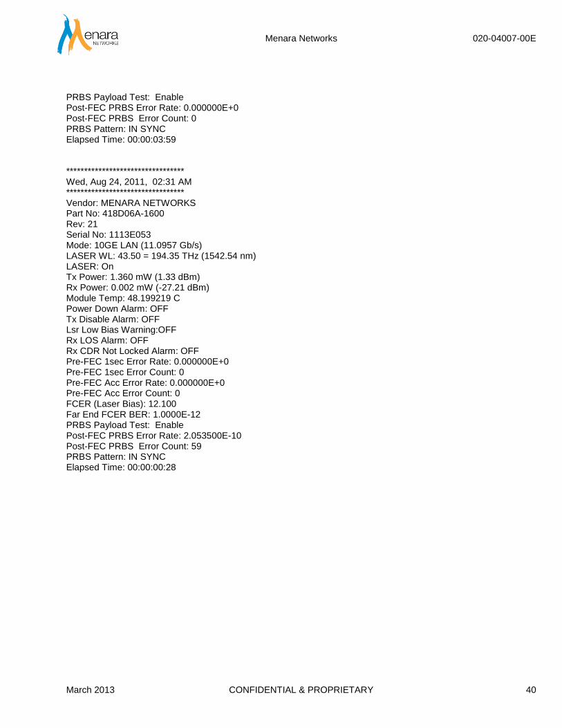
Appendix B: Saved Data File
Example of saved data is shown below. ********************************* Wed, Aug 24, 2011, 02:25 AM ********************************* Vendor: MENARA NETWORKS Part No: 418D06A-1600 Rev: 21 Serial No: 1113E053 Mode: 10GE LAN (11.0957 Gb/s) LASER WL: 43.50 = 194.35 THz (1542.54 nm) LASER: On Tx Power: 1.363 mW (1.34 dBm) Rx Power: 0.001 mW (-30.97 dBm) Module Temp: 48.640625 C Power Down Alarm: OFF Tx Disable Alarm: OFF Lsr Low Bias Warning:OFF Rx LOS Alarm: OFF Rx CDR Not Locked Alarm: ON Pre-FEC 1sec Error Rate: 8.770221E-4 Pre-FEC 1sec Error Count: 9033328 Pre-FEC Acc Error Rate: 9.207241E-4 Pre-FEC Acc Error Count: 284503762 FCER (Laser Bias): 4.900 Far End FCER BER: 9.0000E-4 PRBS Payload Test: Enable Post-FEC PRBS Error Rate: 5.238906E-7 Post-FEC PRBS Error Count: 192381 PRBS Pattern: IN SYNC Elapsed Time: 00:00:00:36 ********************************* Wed, Aug 24, 2011, 02:30 AM ********************************* Vendor: MENARA NETWORKS Part No: 418D06A-1600 Rev: 21 Serial No: 1113E053 Mode: 10GE LAN (11.0957 Gb/s) LASER WL: 43.50 = 194.35 THz (1542.54 nm) LASER: On Tx Power: 1.361 mW (1.34 dBm) Rx Power: 0.002 mW (-27.21 dBm) Module Temp: 48.640625 C Power Down Alarm: OFF Tx Disable Alarm: OFF Lsr Low Bias Warning:OFF Rx LOS Alarm: OFF Rx CDR Not Locked Alarm: OFF Pre-FEC 1sec Error Rate: 9.708738E-11 Pre-FEC 1sec Error Count: 1 Pre-FEC Acc Error Rate: 3.193413E-10 Pre-FEC Acc Error Count: 671 FCER (Laser Bias): 10.400 Far End FCER BER: 4.0000E-10
Menara Networks 020-04007-00E
March 2013 CONFIDENTIAL & PROPRIETARY 40
PRBS Payload Test: Enable Post-FEC PRBS Error Rate: 0.000000E+0 Post-FEC PRBS Error Count: 0 PRBS Pattern: IN SYNC Elapsed Time: 00:00:03:59 ********************************* Wed, Aug 24, 2011, 02:31 AM ********************************* Vendor: MENARA NETWORKS Part No: 418D06A-1600 Rev: 21 Serial No: 1113E053 Mode: 10GE LAN (11.0957 Gb/s) LASER WL: 43.50 = 194.35 THz (1542.54 nm) LASER: On Tx Power: 1.360 mW (1.33 dBm) Rx Power: 0.002 mW (-27.21 dBm) Module Temp: 48.199219 C Power Down Alarm: OFF Tx Disable Alarm: OFF Lsr Low Bias Warning:OFF Rx LOS Alarm: OFF Rx CDR Not Locked Alarm: OFF Pre-FEC 1sec Error Rate: 0.000000E+0 Pre-FEC 1sec Error Count: 0 Pre-FEC Acc Error Rate: 0.000000E+0 Pre-FEC Acc Error Count: 0 FCER (Laser Bias): 12.100 Far End FCER BER: 1.0000E-12 PRBS Payload Test: Enable Post-FEC PRBS Error Rate: 2.053500E-10 Post-FEC PRBS Error Count: 59 PRBS Pattern: IN SYNC Elapsed Time: 00:00:00:28

Menara Networks 020-04007-00E
March 2013 CONFIDENTIAL & PROPRIETARY 41
Appendix C: Troubleshooting
Problems installing the USB Tuning Cable
- Check that the USB drivers are installed properly by verifying in the device manager that there
are no yellow question marks next to any devices. - Ensure that the USB tuning cable drivers are used and NOT the USB to serial cable drivers.
Drivers can be downloaded at http://www.menaranet.com/GUI/ - If installing on Windows XP use the devtech.inf file when searching for the driver file and not the
usb-devtech.inf or usb-devtech folder. - Administrator access is required to install the USB Tuning cable drivers
Errors when opening Menara Customer GUI
- Ensure that the USB tuning cables are installed properly - If using the serial host board ensure that the USB to serial drivers are installed properly and the
serial host board is plugged in. - Verify the COM port that was selected. The Menara Customer GUI requires that the COM ports
be below 30. Reassign or delete COM ports if a port above 30 was selected. - Check to see if any other Menara GUI software is installed. It may be necessary to uninstall any
previously installed versions and then reinstall the most current version. Questions/Issues: Contact Menara Networks at: [email protected]