mendooran wtp upgrades concept design
TRANSCRIPT

Mendooran WTP
Upgrades Concept
Design
For Warrumbungle Shire Council
WMA1334-05-REP-C
5 November 2020

WMA1334-05-REP-C │ 1
Mendooran WTP Upgrades Concept Design
For Warrumbungle Shire Council
City Water Technology Pty Ltd
ABN 92 052 448 094
26 / 924 Pacific Highway, Gordon, NSW 2072, Australia
T: +61 2 9498 1444
F: +61 2 9498 1666
W: www.citywater.com.au
Issue Date Revision Issued to Prepared by Reviewed by Comments
7/07/2020 A Warrumbungle Shire Council
JC, CS JC/ BM First draft
23/07/2020 B Warrumbungle Shire Council
JC, CS JC Updated in line with Concept Design Workshop discussions
05/11/2020 C Warrumbungle Shire Council
CS MMC Minor updates to align with technical specification and removed “draft” watermark.
WMA1334-05-REP-C │ 2
Contents
Definitions 8
1 Introduction 10
1.1 Background 10
1.2 Reference Documents and Supporting Evidence 10
1.3 Objectives 13
1.4 Further Investigation 14
2 Existing System 15
2.1 Demand 15
2.2 Catchment 15
2.3 Start/ Stop Control of Plant and Flow Balancing 15
2.4 Raw Water Extraction 16
2.5 Water Treatment Plant and Reticulation 17
2.6 Water Quality Statistical Analysis 18
2.6.1 Raw Water Quality Data 18
2.6.2 Settled and Filtered Water Quality 20
2.6.3 Sedimentation Lagoon Performance 21
2.7 Process Flow Diagram 21
3 Project Scope 23
3.1 Scope of Works Overview 23
3.1.1 Project Timing 23
3.1.2 Small Works Packages 23
3.1.3 Additional Work Packages 23
3.1.4 Scope of Works’ Activities 24
3.2 Preferred Treatment Process 26
3.3 Process Equipment Status and Requirements 26
3.4 Project Limits 28
3.5 Project Exclusions 29
3.6 Process Flow Diagram for Concept Design Scope of Works 30
4 Design Requirements 32
4.1 General Considerations 32
4.2 Process Requirements 32
4.2.1 Preferred Treatment Process 32
4.2.2 Design Capacities 32
WMA1334-05-REP-C │ 3
4.2.3 Multi-Barrier Approach 34
4.1 Treated Water Quality Targets 34
ADWG (2011) Treated Water Quality Targets 34
WSAA (2015) Health-Based Pathogen Log Removal Targets 35
4.2 Buildings 37
4.3 Power Supply 37
4.4 Telemetry and Control Systems 37
4.5 Documentation 37
4.6 Training 38
5 Site Layout 39
5.1 Castlereagh River Pumps Site 39
5.2 Old Raw Water Pump Station Site 39
5.3 Mendooran WTP Site Layout 39
5.4 Mendooran Standpipe Site Layout 39
5.5 Coolabah Reservoirs Site Layout 40
6 Work Package 1: Raw Water Supply and Blending 41
6.1 Description of works 41
6.1.1 Overview 41
6.1.2 Process Description 41
6.1.3 Location of Works 42
6.2 Assumptions 42
6.3 Design Requirements 43
6.3.1 Raw Water Supply 43
6.3.2 Blending Tank 43
6.4 Concept Design Calculations 44
7 Work Package 2: Chemical Dosing Facilities 45
7.1 Description of works 45
7.1.1 Overview 45
7.1.2 Process Description 45
7.1.3 Location of works 46
7.2 Design Requirements 47
7.2.1 Design Basis 47
7.2.2 Design Chemical Dose Rates 48
7.3 Concept Design Calculations for Chemical Dosing Facilities 48
7.3.1 Soda Ash 48

WMA1334-05-REP-C │ 4
7.3.2 Potassium Permanganate 49
7.3.3 Polyaluminium Chloride 50
7.3.4 Cationic Polymer LT22SS 51
7.3.5 Chlorine Gas 52
7.4 Concept Design for Inline Mixer 55
7.4.1 General 55
7.4.2 Design Requirements 55
7.5 Concept Design for Service Water Pumps 55
7.5.1 General 55
7.5.2 Design Requirements 56
7.5.3 Concept Design Calculations 56
7.6 Concept Design for Wastewater Holding Tank 57
7.6.1 General 57
7.6.2 Design Requirements 57
7.7 Safety in Design Considerations 57
8 Work Package 3: Online Instrumentation & Process Control 60
8.1 Description of works 60
8.1.1 Overview 60
8.1.2 General 60
8.1.3 Performance Requirements 61
8.1.4 Summary of Instruments and Requirements 61
8.2 Instrument List and Controls 62
8.3 Critical Control Points 65
8.4 Alarm Lists 66
8.5 Raw Water Supply 67
8.6 Chemical Dosing Systems 68
8.6.1 Soda Ash 68
8.6.2 Potassium Permanganate 68
8.6.3 Polyaluminium Chloride (PACl) 69
8.6.4 Polymer 69
8.6.5 Chlorine Dosing 70
8.7 Filtration and Backwash Control 72
9 Work Package 4: Mendooran Standpipe Booster Pumps and Standpipe Modifications 73
9.1 Description of works 73
9.1.1 Overview 73
WMA1334-05-REP-C │ 5
9.1.2 Process Description 73
9.1.3 Location of Works 73
9.2 Design Requirements 73
9.3 Concept Design 74
9.3.1 Standpipe Booster Pumps 74
9.3.2 Mendooran Standpipe Modifications 75
9.4 Safety in Design 75
10 Work Package 5: Management of Coolabah Reservoirs’ Water Age and Reservoir Modifications 77
10.1 Description of works 77
10.1.1 Overview 77
10.1.2 Process Description 77
10.1.3 Location of Works and Hydraulic Connections 78
10.2 Design Requirements 78
10.3 Concept Design 79
10.3.1 Management of Water Age 79
10.3.2 Chlorine Gas for Booster Chlorination 79
10.3.3 Coolabah Reservoir Modifications 79
11 Work Package 6: Replacement of Sludge Lagoons with Clarifier 80
11.1 Description of works 80
11.1.1 Overview 80
11.1.2 Process Description 80
11.1.3 Location of Works 81
11.2 Design Requirements 81
11.3 Concept Design Calculations 82
12 Work Package 8: Installation of UV Disinfection Unit 83
12.1 Description of Works 83
12.1.1 Overview 83
12.1.2 Process Description 83
12.2 Design Requirements 83
12.3 Concept Design Calculations 84
13 References 85

WMA1334-05-REP-C │ 6
Figures
Figure 2-1 Existing Mendooran WTP and Reticulation ............................................................................................... 22
Figure 3-1 Proposed Scope of Works (in red) for new Mendooran WTP Concept Design ............................................. 31
Figure 5-1 Mendooran WTP Site Layout (SixMaps 2020) ............................................................................................ 39
Figure 5-2 Mendooran Standpipe Site Layout (SixMaps 2020) .................................................................................. 40
Figure 5-3 Coolabah Reservoirs Site Layout (SixMaps 2020) ..................................................................................... 40
Figure 6-1 Schematic of Work Package 1 .................................................................................................................. 42
Figure 11-1 Example of Inclined Plate 200 GPM Clarifier (HydroFlow, 2020) .............................................................. 80
Tables
Table 1-1: Documentation References ....................................................................................................................... 10
Table 2-1: Mendooran WTP Raw Water Storages....................................................................................................... 16
Table 2-2: Mendooran WTP Process Description ....................................................................................................... 17
Table 2-3: Mendooran WTP operating data ............................................................................................................... 19
Table 2-4: Statistical Summary of Inter-Process Water Quality Data (Jun 2017 – Oct 2019) ....................................... 20
Table 3-1: Scope of Works and Activities ................................................................................................................... 24
Table 3-2: Process Equipment Status and Requirements............................................................................................ 27
Table 4-1: Capacity Metrics from IWCMP ................................................................................................................... 33
Table 4-2: Design Capacities for Concept Design ....................................................................................................... 33
Table 4-3: Treatment Barriers Against Key Hazards ................................................................................................... 34
Table 4-4: ADWG Recommended Treated Water Quality Targets.............................................................................. 34
Table 4-5: WSAA Recommended Health-Based Treated Water Quality Targets ........................................................ 35
Table 4-6: Theoretical Log Reduction Capacity of Stage 1 Mendooran WTP .............................................................. 36
Table 4-7: Theoretical Log Reduction Capacity of Stage 2 Mendooran WTP .............................................................. 36
Table 6-1: Work Package 1 - Scope of Works and Activities ........................................................................................ 41
Table 6-2: Work Package 1 – Location of Works ........................................................................................................ 42
Table 6-3: Blending Tank Design Basis, Assumptions and Calculations ..................................................................... 44
Table 7-1: Scope of Works and Activities ................................................................................................................... 45
Table 7-2: Chemicals and Purpose ............................................................................................................................. 45
Table 7-3: Location of Works ..................................................................................................................................... 46
Table 7-4: Chemical Dose Rates ................................................................................................................................ 48
Table 7-5: Chemical Dose Rates and Product Consumption ...................................................................................... 49
Table 7-6: Chemical Dose Rates and Product Consumption ...................................................................................... 50
Table 7-7: Chemical Dose Rates and Product Consumption ........................................................................................ 51
Table 7-8: Chemical Dose Rates and Product Consumption ...................................................................................... 52
Table 7-9: Chemical Dose Rates and Product Consumption ...................................................................................... 54
Table 7-10: Chemical Dose Rates and Product Consumption ..................................................................................... 54
Table 7-11: Coagulation System Options Design ........................................................................................................ 55
Table 8-1: Scope of Works and Activities................................................................................................................... 60
Table 8-2: Summary of Instrumentation, Location and Requirements ....................................................................... 61
Table 8-3: Preliminary Instrument List ...................................................................................................................... 62
Table 8-4: Recommendation for Revised CCPs at Mendooran WTP .......................................................................... 66
Table 8-5: Preliminary WTP Alarm List...................................................................................................................... 66
Table 9-1: Work Package 4 - Scope of Works and Activities ....................................................................................... 73
WMA1334-05-REP-C │ 7
Table 9-2: Work Package 4 - Location of Works ......................................................................................................... 73
Table 9-3: Service pressure limit recommendations, subject to pressure testing ........................................................ 74
Table 9-4: Mendooran Booster Pumps Design Summary ........................................................................................... 75
Table 9-5: Scope of Mendooran Standpipe modifications .......................................................................................... 75
Table 10-1: Scope of Works and Activities .................................................................................................................. 77
Table 10-2: Location of Works and Hydraulic Connections ......................................................................................... 78
Table 10-3: Work Package 5 - Design Requirements ................................................................................................... 78
Table 10-4: UV Disinfection Unit Design Basis, Assumptions and Calculations ........................................................... 79
Table 10-5: Coolabah Reservoir Modifications ........................................................................................................... 79
Table 11-1: Scope of Works and Activities ................................................................................................................. 80
Table 11-2: Location of Works .................................................................................................................................... 81
Table 11-3: Summary of Design Requirements ........................................................................................................... 81
Table 11-4: Clarifier Design Basis, Assumptions and Calculations .............................................................................. 82
Table 12-1: Scope of Works and Activities .................................................................................................................. 83
Table 12-2 :UV Disinfection Unit Design Basis, Assumptions and Calculations .......................................................... 84

WMA1334-05-REP-C │ 8
Definitions
ADWG Australian Drinking Water Guidelines
BF Baffle Factor
CCP Critical Control Point
Contractor Term used interchangeably with successful tenderer to refer to the organisation
responsible for delivery all components of work described in this document
CWT City Water Technology
DBP Disinfection By-Products
DOC Dissolved Organic Carbon
DWMS Drinking Water Management System
‘Good Practice Guide’ Refers to Good Practice Guide to the Operation of Drinking Water Supply Systems for the
Management of Microbial Risk (WSAA/WRA, 2015)
‘Guidelines’ Refers to the Australian Drinking Water Guidelines (NHMRC, 2011)
HBT Health Based Target
HBT Manual Abbreviation for Manual for the Application of Health-Based Treatment Targets (WSAA,
2015).
KMnO4 Potassium Permanganate
LRV Log Reduction Value
‘Manual’ Refers to the Manual for the Application of Health-Based Treatment Targets (WSAA,
2015)
Mn Chemical symbol for manganese
NaOCl Sodium Hypochlorite
NTU Nephelometric Turbidity Unit
PACl Polyaluminium Chloride
PHA Preliminary Hazard Assessment
PFD Process Flow Diagram
RTU Remote Terminal Unit
Sedimentation Lagoon Existing sedimentation lagoons No.1 and 2
Wastewater Lagoon Existing sedimentation lagoons No.1 and 2 repurposed into wastewater lagoons. This is
associated with installation of a clarifier.

WMA1334-05-REP-C │ 9
Tenderer Organisation presenting a bid for the Design and Construct Contract for Mendooran
WTP upgrades
THM Trihalomethanes
TDS Total Dissolved Solids
TSS Total Suspended Solids
T&O Tastes & Odours; often due to the presence of algae
UPS Uninterruptable Power Supply
UVT UV Transmissivity (units: %)
VSD Variable Speed Drive
WHS Work Health and Safety (previously OHS Occupational Health and Safety)
WSAA Water Services Association of Australia; authors of the Manual for the Application of
Health-Based Treatment Targets (2015) and co-author of Good Practice Guide to the
Operation of Drinking Water Supply Systems for the Management of Microbial Risk (2015)
WRA Water Research Australia; co-author of Good Practice Guide to the Operation of Drinking
Water Supply Systems for the Management of Microbial Risk (2015)
WSC Warrumbungle Shire Council
WSS Water Supply System/ Scheme
WTP Water Treatment Plant
WQ Water Quality

WMA1334-05-REP-C │ 10
1 Introduction
1.1 Background
CWT were engaged by Warrumbungle Shire Council (WSC) to assess options and design upgrades for the Mendooran
Water Treatment Plant (WTP) and reticulation.
The existing Mendooran WTP supplies treated water to the Mendooran and Coolabah areas. Mendooran WTP was
constructed in 2009 and has a capacity of ~1.0 ML/day.
In 2015, City Water Technology (CWT) was engaged by NSW Health to offer support to numerous utilities for WTP
process review. CWT visited Mendooran WTP and in May 2015 submitted an audit report. Several recommendations
were provided in the WSC742-02-A Mendooran WTP Audit Report, of which many issues remain unresolved.
Up until 2019, several other incident investigations and site inspections were performed, noting several process
deficiencies, water quality issues and work health and safety concerns. Between April 2017 and June 2017 E. Coli was
also detected in the reticulation and led to a boil water notice being issued to the Mendooran and Coolabah customers.
Water security in the region is also an issue for concern; in November 2019 Mendooran was placed on Level 2
restrictions, Level 3 in December 2018, then Level 5 and 6 in Jan 2019.
In May 2020 CWT (Jess Circosta, Christina Saxvik) facilitated a preliminary hazard assessment (PHA) by teleconference
with WSC (Cornelia Wiebels, Andrew Milford and Stephen Drew). The purpose of the PHA was to ensure that packages
of works identified in Council’s Brief were sufficient to mitigate known process deficiencies, water quality issues and
work health and safety concerns. However, from the PHA, CWT’s recent site visit and other investigations (see Section
1.2), CWT identified the need for additional works.
These works, together with those described in Council’s Brief shall be address further by this concept design.
1.2 Reference Documents and Supporting Evidence
Previous projects have been facilitated by Council in an effort to identify and mitigate issues to operability and safety,
treatability, current and future water quality.
Table 1-1 provides a summary of reference documents and supporting evidence used for the development of this
concept design.
Table 1-1: Documentation References
Report Title Author Year Description
Mendooran Water
Treatment Plant –
Operation of Equipment
Manual
Water Treatment
Australia
2010 Operations manual and control philosophy of the
Mendooran WTP. WTA’s scope of works included the
“Filtration Plant” and “Chemical Dosing”. This document was
intended as a guide for YORECON to develop their detailed
functional description.
Mendooran WTP Audit
Report
Hunter Water Australia/
Lower Macquarie
Water Utilities Alliance
2014 This report documented several WTP deficiencies, including
the information systems for the WTP, the overall process,
safety and security.
WMA1334-05-REP-C │ 11
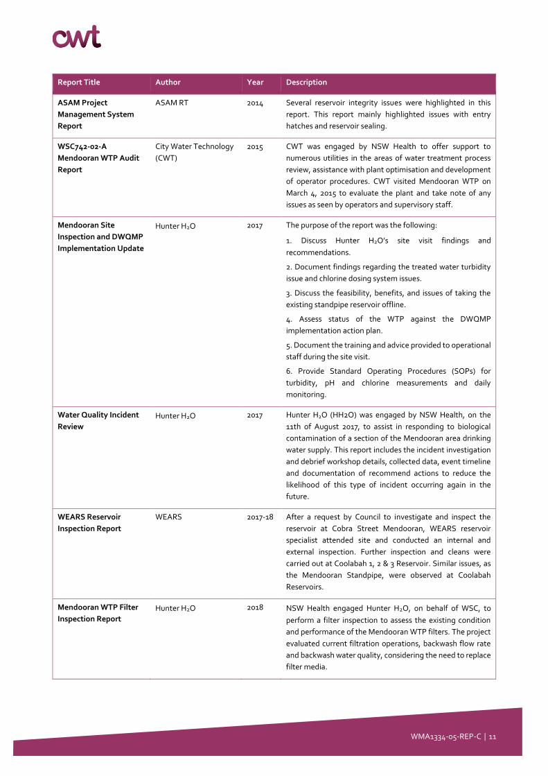
Report Title Author Year Description
ASAM Project
Management System
Report
ASAM RT 2014 Several reservoir integrity issues were highlighted in this
report. This report mainly highlighted issues with entry
hatches and reservoir sealing.
WSC742-02-A
Mendooran WTP Audit
Report
City Water Technology
(CWT)
2015 CWT was engaged by NSW Health to offer support to
numerous utilities in the areas of water treatment process
review, assistance with plant optimisation and development
of operator procedures. CWT visited Mendooran WTP on
March 4, 2015 to evaluate the plant and take note of any
issues as seen by operators and supervisory staff.
Mendooran Site
Inspection and DWQMP
Implementation Update
Hunter H2O 2017 The purpose of the report was the following:
1. Discuss Hunter H2O’s site visit findings and
recommendations.
2. Document findings regarding the treated water turbidity
issue and chlorine dosing system issues.
3. Discuss the feasibility, benefits, and issues of taking the
existing standpipe reservoir offline.
4. Assess status of the WTP against the DWQMP
implementation action plan.
5. Document the training and advice provided to operational
staff during the site visit.
6. Provide Standard Operating Procedures (SOPs) for
turbidity, pH and chlorine measurements and daily
monitoring.
Water Quality Incident
Review
Hunter H2O 2017 Hunter H2O (HH2O) was engaged by NSW Health, on the
11th of August 2017, to assist in responding to biological
contamination of a section of the Mendooran area drinking
water supply. This report includes the incident investigation
and debrief workshop details, collected data, event timeline
and documentation of recommend actions to reduce the
likelihood of this type of incident occurring again in the
future.
WEARS Reservoir
Inspection Report
WEARS 2017-18 After a request by Council to investigate and inspect the
reservoir at Cobra Street Mendooran, WEARS reservoir
specialist attended site and conducted an internal and
external inspection. Further inspection and cleans were
carried out at Coolabah 1, 2 & 3 Reservoir. Similar issues, as
the Mendooran Standpipe, were observed at Coolabah
Reservoirs.
Mendooran WTP Filter
Inspection Report
Hunter H2O 2018 NSW Health engaged Hunter H2O, on behalf of WSC, to
perform a filter inspection to assess the existing condition
and performance of the Mendooran WTP filters. The project
evaluated current filtration operations, backwash flow rate
and backwash water quality, considering the need to replace
filter media.

WMA1334-05-REP-C │ 12
Report Title Author Year Description
Mendooran WTP
Remote Alarming
Report
Hunter H2O 2018 Warrumbungle Shire Council (WSC) via NSW Health
engaged Hunter H2O to inspect the WTP control system and
provide further advice and recommendations on the
required alarm dialler system, as there was no remote
alarming at the WTP.
Mendooran Reservoir
Upgrade Report 2019
WEARS 2019 Several reservoir integrity issues were addressed in this
report, mainly on entry hatches and reservoir sealing.
Additional issues were highlighted in this report, including
access structures and reservoir mixing.
WIS – Mendooran –
Cobra Street – Visual
Inspection
Water Infrastructure
Services
2019 This report highlighted any defects and inherent risks
associated with the operations and maintenance of the
Mendooran Standpipe Reservoir.
Mendooran WTP
Emergency Ops Support
Report April 2019
Hunter H2O 2019 Hunter H2O was engaged by NSW Health and WSC to
provide emergency operational support to Mendooran WTP.
The purpose of the operational support visit was to identify
possible solutions to algae issues and determine if it is
possible to increase the current operational capacity.
Representatives from WSC, Hunter H2O, Department of
Industry Water and NSW Health attended the site and
discussed the current situation and identify pathways to
removing water restrictions while preventing algal blooms in
the sedimentation lagoons.
Mendooran WTP Site
Constraint and Hazard
Review Report
City Water Technology
(CWT)
2019 CWT was engaged by Warrumbungle Shire Council (WSC) to
assess options for upgrades at Mendooran Water Treatment
Plant (WTP) and to develop a concept design and technical
specification for several upgrade packages.
The purpose of this report was to summarise the process
issues identified during the site visit conducted by City Water
Technology (CWT) on November 14th, 2019. This report
provides the background information needed to develop the
proposed upgrade options for the WTP, which will be
described in the WMA1334-03-REP Mendooran Design Basis
and Options Assessment Report.
Mendooran WTP
Design Basis and
Options Assessment
Report
City Water Technology
(CWT)
2019 CWT was engaged by Warrumbungle Shire Council (WSC) to
assess options for upgrades at Mendooran Water Treatment
Plant (WTP) and to develop a concept design and technical
specification for several upgrade packages.
The purpose of this report was to help address process issues
identified in the WMA1334-02-REP Mendooran
WTP Site Constraint and Preliminary Hazard Review Report
by listing the upgrade options available. This report also
provides a design basis that will be used in the development
of the WTP upgrade concept designs.
Mendooran WTP City Water Technology
(CWT)
2020 CWT was engaged by Warrumbungle Shire Council (WSC) to
assess options for upgrades at Mendooran Water Treatment
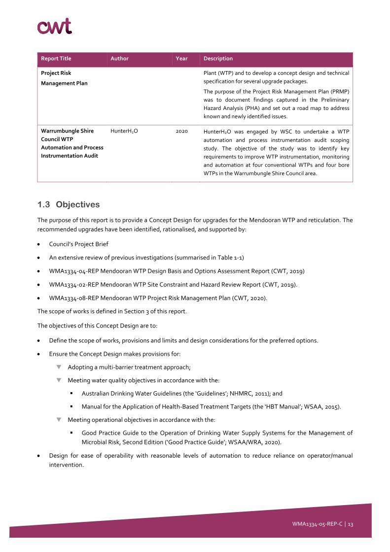
WMA1334-05-REP-C │ 13
Report Title Author Year Description
Project Risk
Management Plan
Plant (WTP) and to develop a concept design and technical
specification for several upgrade packages.
The purpose of the Project Risk Management Plan (PRMP)
was to document findings captured in the Preliminary
Hazard Analysis (PHA) and set out a road map to address
known and newly identified issues.
Warrumbungle Shire
Council WTP
Automation and Process
Instrumentation Audit
HunterH2O 2020 HunterH2O was engaged by WSC to undertake a WTP
automation and process instrumentation audit scoping
study. The objective of the study was to identify key
requirements to improve WTP instrumentation, monitoring
and automation at four conventional WTPs and four bore
WTPs in the Warrumbungle Shire Council area.
1.3 Objectives
The purpose of this report is to provide a Concept Design for upgrades for the Mendooran WTP and reticulation. The
recommended upgrades have been identified, rationalised, and supported by:
• Council’s Project Brief
• An extensive review of previous investigations (summarised in Table 1-1)
• WMA1334-04-REP Mendooran WTP Design Basis and Options Assessment Report (CWT, 2019)
• WMA1334-02-REP Mendooran WTP Site Constraint and Hazard Review Report (CWT, 2019).
• WMA1334-08-REP Mendooran WTP Project Risk Management Plan (CWT, 2020).
The scope of works is defined in Section 3 of this report.
The objectives of this Concept Design are to:
• Define the scope of works, provisions and limits and design considerations for the preferred options.
• Ensure the Concept Design makes provisions for:
Adopting a multi-barrier treatment approach;
Meeting water quality objectives in accordance with the:
▪ Australian Drinking Water Guidelines (the ‘Guidelines’; NHMRC, 2011); and
▪ Manual for the Application of Health-Based Treatment Targets (the ‘HBT Manual’; WSAA, 2015).
Meeting operational objectives in accordance with the:
▪ Good Practice Guide to the Operation of Drinking Water Supply Systems for the Management of
Microbial Risk, Second Edition (‘Good Practice Guide’; WSAA/WRA, 2020).
• Design for ease of operability with reasonable levels of automation to reduce reliance on operator/manual
intervention.

WMA1334-05-REP-C │ 14
1.4 Further Investigation
This Concept Design has been established based on data made available as of December 2019.
Additional data is recommended to further support this concept design and to be made available prior to the tendering
phase.
This includes but is not limited to:
• Ongoing raw water quality monitoring from the various raw water sources to provide confidence in the selection
and sizing of chemical dosing systems.
• Jar testing of raw water quality to provide confidence for the selection of dosed chemicals and their dose ranges.
• Geotechnical surveying for the purposes of an installation of a new Clarifier and/or extension of existing Sludge
Lagoons etc.
• Condition assessments and/or pressure testing of reticulation pipework extending from the Mendooran
Standpipe. Integration of the Mendooran Standpipe booster pumps would increase reticulation supply pressure.
Testing should be performed to help prevent future pipe ruptures.
WMA1334-05-REP-C │ 15
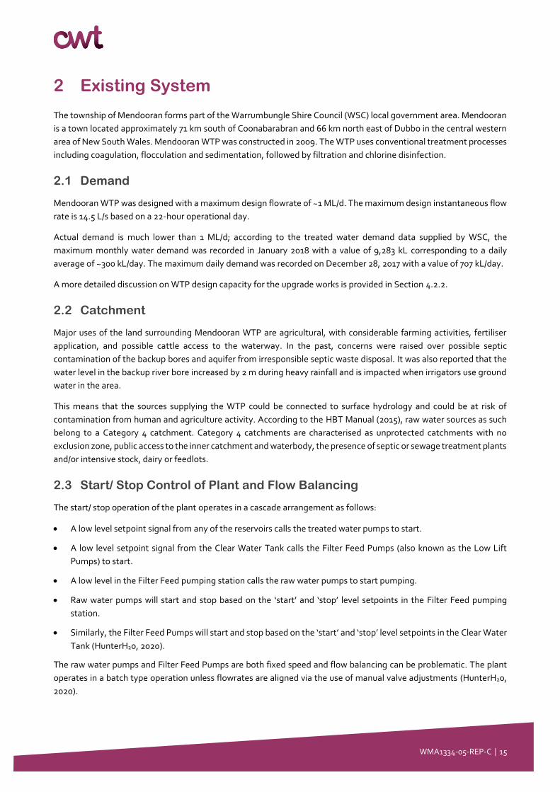
2 Existing System
The township of Mendooran forms part of the Warrumbungle Shire Council (WSC) local government area. Mendooran
is a town located approximately 71 km south of Coonabarabran and 66 km north east of Dubbo in the central western
area of New South Wales. Mendooran WTP was constructed in 2009. The WTP uses conventional treatment processes
including coagulation, flocculation and sedimentation, followed by filtration and chlorine disinfection.
2.1 Demand
Mendooran WTP was designed with a maximum design flowrate of ~1 ML/d. The maximum design instantaneous flow
rate is 14.5 L/s based on a 22-hour operational day.
Actual demand is much lower than 1 ML/d; according to the treated water demand data supplied by WSC, the
maximum monthly water demand was recorded in January 2018 with a value of 9,283 kL corresponding to a daily
average of ~300 kL/day. The maximum daily demand was recorded on December 28, 2017 with a value of 707 kL/day.
A more detailed discussion on WTP design capacity for the upgrade works is provided in Section 4.2.2.
2.2 Catchment
Major uses of the land surrounding Mendooran WTP are agricultural, with considerable farming activities, fertiliser
application, and possible cattle access to the waterway. In the past, concerns were raised over possible septic
contamination of the backup bores and aquifer from irresponsible septic waste disposal. It was also reported that the
water level in the backup river bore increased by 2 m during heavy rainfall and is impacted when irrigators use ground
water in the area.
This means that the sources supplying the WTP could be connected to surface hydrology and could be at risk of
contamination from human and agriculture activity. According to the HBT Manual (2015), raw water sources as such
belong to a Category 4 catchment. Category 4 catchments are characterised as unprotected catchments with no
exclusion zone, public access to the inner catchment and waterbody, the presence of septic or sewage treatment plants
and/or intensive stock, dairy or feedlots.
2.3 Start/ Stop Control of Plant and Flow Balancing
The start/ stop operation of the plant operates in a cascade arrangement as follows:
• A low level setpoint signal from any of the reservoirs calls the treated water pumps to start.
• A low level setpoint signal from the Clear Water Tank calls the Filter Feed Pumps (also known as the Low Lift
Pumps) to start.
• A low level in the Filter Feed pumping station calls the raw water pumps to start pumping.
• Raw water pumps will start and stop based on the ‘start’ and ‘stop’ level setpoints in the Filter Feed pumping
station.
• Similarly, the Filter Feed Pumps will start and stop based on the ‘start’ and ‘stop’ level setpoints in the Clear Water
Tank (HunterH20, 2020).
The raw water pumps and Filter Feed Pumps are both fixed speed and flow balancing can be problematic. The plant
operates in a batch type operation unless flowrates are aligned via the use of manual valve adjustments (HunterH20,
2020).

WMA1334-05-REP-C │ 16
Plant raw water flowrate and settled water flowrate (filtered water flowrate) is set via manual valves (HunterH20, 2020).
Treated water is preferentially supplied to the Mendooran Standpipe until the high level setpoint is reached, upon
which a control valve closes and thus directs treated water to the Coolabah reservoirs. A high level in the Coolabah
reservoirs triggers the treated water pumps to stop (HunterH20, 2020).
2.4 Raw Water Extraction
Mendooran WTP can draw water from several sources, which include the following:
• Castlereagh Riverbed: Two submersible pumps (duty/standby) located in a pump well, supplied by intake screens
located underneath the Castlereagh Riverbed.
These pumps feed a DN150 rising main, pumping water to the WTP approximately 850 m away.
Based on the results of the site visit, the ground surface water appeared stagnant with minimal river water
flow at the extraction point. However, there is reportedly an under-river drift channel that continues to
supply water to the raw water pumps.
According to the “Conceptual Hydraulic Profile (Work as Executed)” drawing #0700910-04, the raw water
pumps operate at 14.5 L/s.
Based on review of the provided P&IDs, it is assumed that these pumps are not VSD controlled.
• Backup bore: A 25 m deep back-up bore reportedly 20 m from the riverbed. The backup bore pipework is connected
to the WTP rising main.
Based on review of the provided P&IDs, it is been assumed that their design flow rate is 4 L/s. WSC has
indicated that they expect that this flowrate is higher than 4 L/s, therefore the flowrate is to be reported as
‘>4 L/s’ further in this report. Although the P&IDs indicate VSD control, Council has reported that this supply
operates at fixed flow and does not contain VSDs.
• Emergency onsite bore: An onsite WTP bore, which is intended for use in emergency.
It was reported by Council that this bore can only provide a fixed raw water flow rate of 0.8 L/s to the WTP.
For a 22-hour operational day, this equates to 0.06 ML/d.
This water is pumped directly to the inlet of the cascade aerator and is not connected to the WTP main.
• Old river pump station: This pump station was the previous raw water supply for the town but was taken offline
once the WTP was built. Council applied for funding to install a pipeline between the pump station and the existing
rising main into the WTP. This work has now been completed and there are reportedly two operable 6”
submersible pumps with VSDs in the riverbank well. This supply is missing process control implementation;
however, this is soon to be commissioned by another contractor.
Table 2-1 summarises data on the available raw water sources.
Table 2-1: Mendooran WTP Raw Water Storages
Raw water Source Pump configuration Duty (L/s, kL/h) Fixed or Variable flow
Castlereagh Riverbed 2 × duty/standby 14.5, 52.2 Fixed
Backup Bore 1 × duty >4.0, >14.4 Fixed
Emergency Onsite Bore 1 × duty 0.8, 2.88 Fixed
WMA1334-05-REP-C │ 17
Raw water Source Pump configuration Duty (L/s, kL/h) Fixed or Variable flow
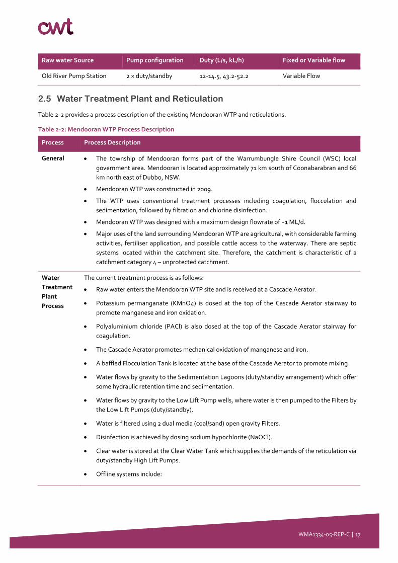
Old River Pump Station 2 × duty/standby 12-14.5, 43.2-52.2 Variable Flow
2.5 Water Treatment Plant and Reticulation
Table 2-2 provides a process description of the existing Mendooran WTP and reticulations.
Table 2-2: Mendooran WTP Process Description
Process Process Description
General • The township of Mendooran forms part of the Warrumbungle Shire Council (WSC) local
government area. Mendooran is located approximately 71 km south of Coonabarabran and 66
km north east of Dubbo, NSW.
• Mendooran WTP was constructed in 2009.
• The WTP uses conventional treatment processes including coagulation, flocculation and
sedimentation, followed by filtration and chlorine disinfection.
• Mendooran WTP was designed with a maximum design flowrate of ~1 ML/d.
• Major uses of the land surrounding Mendooran WTP are agricultural, with considerable farming
activities, fertiliser application, and possible cattle access to the waterway. There are septic
systems located within the catchment site. Therefore, the catchment is characteristic of a
catchment category 4 – unprotected catchment.
Water
Treatment
Plant
Process
The current treatment process is as follows:
• Raw water enters the Mendooran WTP site and is received at a Cascade Aerator.
• Potassium permanganate (KMnO4) is dosed at the top of the Cascade Aerator stairway to
promote manganese and iron oxidation.
• Polyaluminium chloride (PACl) is also dosed at the top of the Cascade Aerator stairway for
coagulation.
• The Cascade Aerator promotes mechanical oxidation of manganese and iron.
• A baffled Flocculation Tank is located at the base of the Cascade Aerator to promote mixing.
• Water flows by gravity to the Sedimentation Lagoons (duty/standby arrangement) which offer
some hydraulic retention time and sedimentation.
• Water flows by gravity to the Low Lift Pump wells, where water is then pumped to the Filters by
the Low Lift Pumps (duty/standby).
• Water is filtered using 2 dual media (coal/sand) open gravity Filters.
• Disinfection is achieved by dosing sodium hypochlorite (NaOCl).
• Clear water is stored at the Clear Water Tank which supplies the demands of the reticulation via
duty/standby High Lift Pumps.
• Offline systems include:

WMA1334-05-REP-C │ 18
Process Process Description
o Soda Ash Dosing System for pH control and Fluoride Dosing System. They are present but
these systems are not in use. The Soda Ash Dosing System has been used for spare parts.
The Fluoride Dosing System requires redesign and recommissioning. A separate
contractor is engaged by Council to re-design the Fluoride Dosing System.
Reservoirs
and
Reticulation
• Treated water from the Clear Water Tank is transferred via the High Lift Pumps to a dedicated
pipe feeding the reservoir system.
o The reticulation contains 4 reservoirs with a combined capacity of 1.06 ML.
o The Mendooran Standpipe Reservoir is located on the corner of Brambil St and Cobra St
and has a capacity of 0.55 ML.
o There are 3 reservoirs located in the Coolabah reticulation zone on Manusu Drive, which
are Coolabah Reservoirs No. 1, 2 and 3. These have a capacity of 0.09, 0.09 and 0.33 ML
respectively.
o The Coolabah Reservoirs have a top water level elevation higher than the Mendooran
Standpipe Reservoir.
• The Coolabah Reservoir site has a sodium hypochlorite Booster Chlorination System on the
common inlet/outlet water main.
2.6 Water Quality Statistical Analysis
2.6.1 Raw Water Quality Data
As reported in the HunterH2o Mendooran WTP Filter Service “15 Point Check” Report, the plant data prior to June 2017
does not appear to be reliable due to inconsistencies with recorded filtered turbidity data and the poor condition of the
WTP. To enable meaningful data analysis, only the data after June 2017 has been considered.
Based on discussion with operations staff and the provided plant monitoring data, the following assumptions have
been made for the river water pumps and backup bore data sets:
• All raw water data before 21/12/2018 corresponds to water from the river water pump station. This is assumed as
the monitoring data does not provide comment as to whether “bore” or “river” water is used.
• Monitoring data from 21/12/2018 until 29/08/19 indicates which raw water source, between the river water pump
station and the backup river bore, was used.
• Monitoring data after 29/08/19 does not indicate which source is used. The operations team has indicated that the
backup river bore was in use until 22/10/19. Council has commented that the backup bore has continued to be the
primary source beyond this date.
The data for the Emergency Onsite Bore was analysed by an external laboratory and reported in the Warrumbungle Shire
Council Water Quality Database spreadsheet. Three samples were dated between 23/08/2017 and 25/08/2017, and a
fourth sample was dated 26/11/2019.
• The data for the Old River Pump Station is a combination of NSW Health recorded data, and on-site testing
performed by Hunter H2O and operational monitoring undertaken by Council.
WMA1334-05-REP-C │ 19
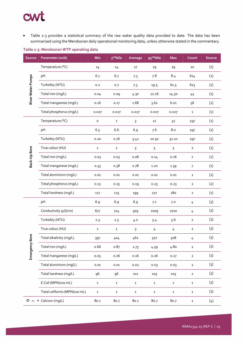
• Table 2-3 provides a statistical summary of the raw water quality data provided to date. The data has been
summarised using the Mendooran daily operational monitoring data, unless otherwise stated in the commentary.
Table 2-3: Mendooran WTP operating data
Source Parameter (unit) Min 5th%ile Average 95th%ile Max Count Source
Riv
er
Wa
ter
Pu
mp
s
Temperature (°C) 14 14 17 19 19 10 [1]
pH 6.1 6.7 7.3 7.8 8.4 614 [1]
Turbidity (NTU) 0.2 0.7 7.3 19.5 61.5 613 [1]
Total iron (mg/L) 0.04 0.09 4.30 12.26 14.50 44 [1]
Total manganese (mg/L) 0.16 0.17 1.68 3.62 6.01 56 [1]
Total phosphorus (mg/L) 0.027 0.027 0.027 0.027 0.027 1 [1]
Ba
ck-U
p B
ore
Temperature (°C) 0 1 3 11 32 197 [1]
pH 6.5 6.6 6.9 7.6 8.0 197 [1]
Turbidity (NTU) 0.20 0.76 3.42 10.50 32.10 197 [1]
True colour (HU) 1 1 3 5 5 2 [1]
Total iron (mg/L) 0.03 0.03 0.06 0.14 0.16 7 [1]
Total manganese (mg/L) 0.53 0.58 0.78 1.20 1.39 7 [1]
Total aluminium (mg/L) 0.01 0.01 0.01 0.01 0.01 1 [1]
Total phosphorus (mg/L) 0.15 0.15 0.19 0.23 0.23 2 [2]
Total hardness (mg/L) 117 125 199 272 280 2 [1]
Em
erg
en
cy B
ore
pH 6.9 6.9 6.9 7.1 7.0 4 [3]
Conductivity (µS/cm) 677 724 919 1009 1010 4 [3]
Turbidity (NTU) 2.3 2.5 4.0 5.4 5.6 2 [3]
True colour (HU) 1 1 3 4 4 2 [3]
Total alkalinity (mg/L) 397 404 462 507 508 4 [3]
Total iron (mg/L) 0.66 0.87 2.73 4.59 4.80 2 [3]
Total manganese (mg/L) 0.05 0.06 0.16 0.26 0.27 2 [3]
Total aluminium (mg/L) 0.01 0.01 0.02 0.03 0.03 2 [3]
Total hardness (mg/L) 96 96 101 105 105 2 [3]
E.Coli (MPN/100 mL) 1 1 1 1 1 1 [3]
Total coliforms (MPN/100 mL) 1 1 1 1 1 1 [3]
O l d
R i v e r P u m p
S t a t i o n
Calcium (mg/L) 80.7 80.7 80.7 80.7 80.7 1 [4]
WMA1334-05-REP-C │ 20
Source Parameter (unit) Min 5th%ile Average 95th%ile Max Count Source
Chloride (mg/L) 353 353 353 353 353 1 [4]
DOC (mg/L) 91.8 91.8 91.8 91.8 91.8 1 [4]
Iron (mg/L) 0.01 0.04 0.27 0.50 0.53 2 [4]
Magnesium (mg/L) 62.60 62.60 62.60 62.60 62.60 1 [4]
Manganese (mg/L) 0.280 0.282 0.304 0.326 0.328 2 [4]
Phosphorus (mg/L) 0.20 0.20 0.20 0.20 0.20 1 [4]
Sodium (mg/L) 388 388 388 388 388 1 [4]
TDS (mg/L) 1,336 1,336.0 1336.0 1336.0 1336.0 1 [4]
Total Hardness (mg/L) 459.30 459.30 459.30 459.30 459.30 1 [4]
True Colour (HU) 1 1 1 1 1 1 [4]
Uranium (mg/L) 0.017 0.017 0.017 0.017 0.017 1 [4]
References:
[1] Mendooran operational monitoring v2.0 Spreadsheet (01/06/2017 to 10/10/2019)
[2] Hunter H2O Mendooran WTP Emergency Ops Support Report (April 2019) (19/02/2019 to 20/02/2019).
[3] External Laboratory, recorded in Warrumbungle Shire Council Water Quality Database spreadsheet (23/8/2017 to
25/08/2017, and 26/11/2019)
[4] Combined data from the Hunter H2O Mendooran WTP Emergency Ops Support Report (April 2019), which includes an NSW Health
data summary (19/02/2019 to 20/02/2019), and Mendooran Operational Monitoring (01/06/2017 to 10/10/2019)
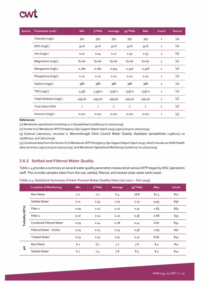
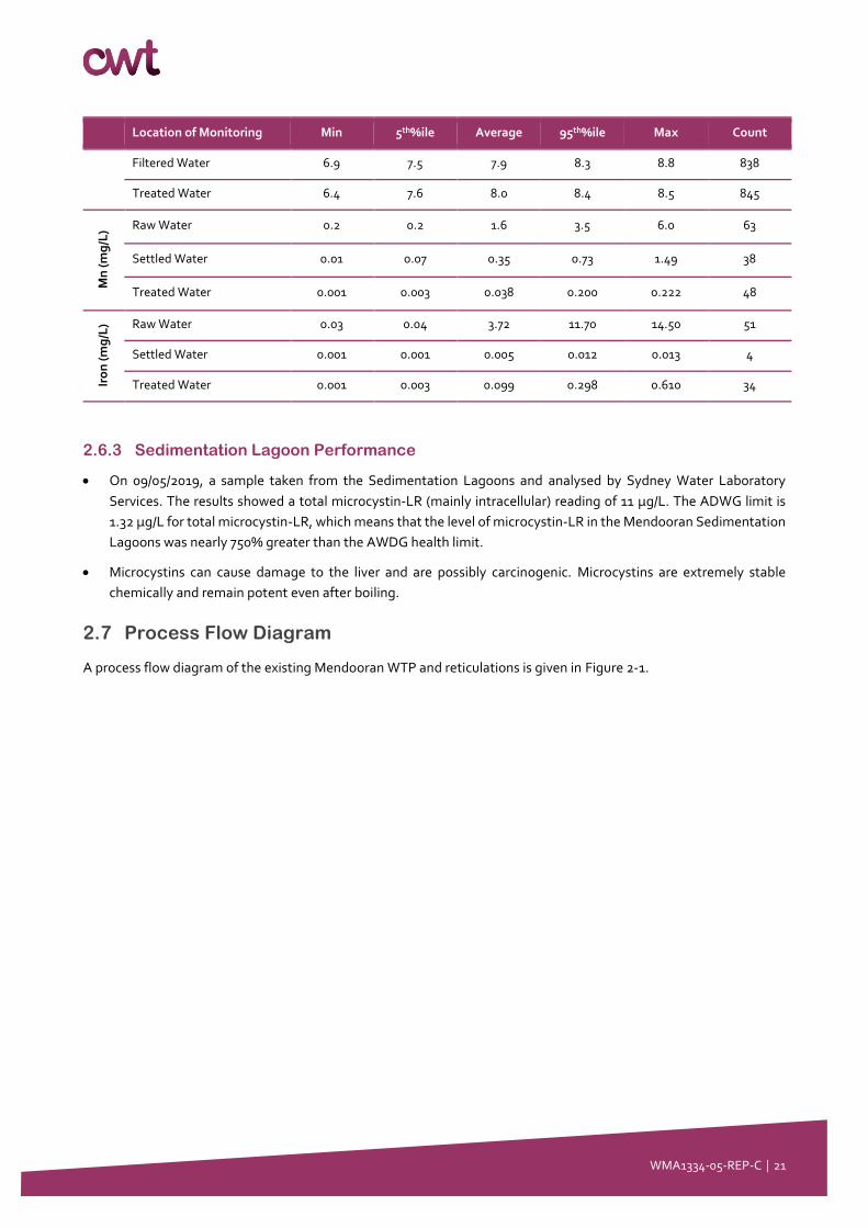
2.6.2 Settled and Filtered Water Quality
Table 2-4 provides a summary on several water quality parameters measured at various WTP stages by WSC operations
staff. This includes samples taken from the raw, settled, filtered, and treated (clear water tank) water.
Table 2-4: Statistical Summary of Inter-Process Water Quality Data (Jun 2017 – Oct 2019)
Location of Monitoring Min 5th%ile Average 95th%ile Max Count
Tu
rbid
ity
(N
TU
)
Raw Water 0.2 0.7 6.4 18.8 61.5 810
Settled Water 0.11 0.34 1.03 2.23 9.93 836
Filter 1 0.09 0.12 0.22 0.37 0.83 663
Filter 2 0.07 0.12 0.21 0.36 0.68 655
Combined Filtered Water 0.09 0.14 0.28 0.42 6.87 834
Filtered Water - Online 0.03 0.04 0.15 0.36 0.69 667
Treated Water 0.03 0.13 0.31 0.47 8.60 840
pH
Raw Water 6.1 6.7 7.2 7.8 8.4 811
Settled Water 6.7 7.4 7.8 8.3 8.5 841
WMA1334-05-REP-C │ 21
Location of Monitoring Min 5th%ile Average 95th%ile Max Count
Filtered Water 6.9 7.5 7.9 8.3 8.8 838
Treated Water 6.4 7.6 8.0 8.4 8.5 845
Mn
(m
g/L
) Raw Water 0.2 0.2 1.6 3.5 6.0 63
Settled Water 0.01 0.07 0.35 0.73 1.49 38
Treated Water 0.001 0.003 0.038 0.200 0.222 48
Iro
n (
mg
/L) Raw Water 0.03 0.04 3.72 11.70 14.50 51
Settled Water 0.001 0.001 0.005 0.012 0.013 4
Treated Water 0.001 0.003 0.099 0.298 0.610 34
2.6.3 Sedimentation Lagoon Performance
• On 09/05/2019, a sample taken from the Sedimentation Lagoons and analysed by Sydney Water Laboratory
Services. The results showed a total microcystin-LR (mainly intracellular) reading of 11 µg/L. The ADWG limit is
1.32 µg/L for total microcystin-LR, which means that the level of microcystin-LR in the Mendooran Sedimentation
Lagoons was nearly 750% greater than the AWDG health limit.
• Microcystins can cause damage to the liver and are possibly carcinogenic. Microcystins are extremely stable
chemically and remain potent even after boiling.
2.7 Process Flow Diagram
A process flow diagram of the existing Mendooran WTP and reticulations is given in Figure 2-1.

WMA1334-05-REP-C │ 22
Figure 2-1 Existing Mendooran WTP and Reticulation
WMA1334-05-REP-C │ 23
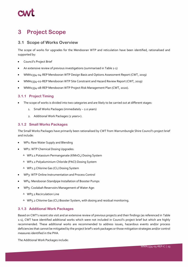
3 Project Scope
3.1 Scope of Works Overview
The scope of works for upgrades for the Mendooran WTP and reticulation have been identified, rationalised and
supported by:
• Council’s Project Brief
• An extensive review of previous investigations (summarised in Table 1-1)
• WMA1334-04-REP Mendooran WTP Design Basis and Options Assessment Report (CWT, 2019)
• WMA1334-02-REP Mendooran WTP Site Constraint and Hazard Review Report (CWT, 2019)
• WMA1334-08-REP Mendooran WTP Project Risk Management Plan (CWT, 2020).
3.1.1 Project Timing
• The scope of works is divided into two categories and are likely to be carried out at different stages:
1. Small Works Packages (immediately – 2.0 years)
2. Additional Work Packages (2 years+).
3.1.2 Small Works Packages
The Small Works Packages have primarily been rationalised by CWT from Warrumbungle Shire Council’s project brief
and include:
• WP1: Raw Water Supply and Blending
• WP2: WTP Chemical Dosing Upgrades:
WP2.1 Potassium Permanganate (KMnO4) Dosing System
WP2.2 Polyaluminium Chloride (PACl) Dosing System
WP2.3 Chlorine Gas (Cl2) Dosing System
• WP3: WTP Online Instrumentation and Process Control
• WP4: Mendooran Standpipe Installation of Booster Pumps
• WP5: Coolabah Reservoirs Management of Water Age:
WP5.1 Recirculation Line
WP5.2 Chlorine Gas (Cl2) Booster System, with dosing and residual monitoring.
3.1.3 Additional Work Packages
Based on CWT’s recent site visit and an extensive review of previous projects and their findings (as referenced in Table
1-1), CWT have identified additional works which were not included in Council’s project brief but which are highly
recommended. These additional works are recommended to address issues, hazardous events and/or process
deficiencies that cannot be mitigated by the project brief’s work packages or those mitigation strategies and/or control
measures identified in the PHA.
The Additional Work Packages include:
WMA1334-05-REP-C │ 24
• WP2.4 Soda ash dosing system
• WP2.5 Polymer dosing system
• WP7 Replacement of Sedimentation Lagoons with Clarifier
• WP8 Installation of UV disinfection unit.
3.1.4 Scope of Works’ Activities
CWT have included all work packages in this Concept Design. However, in keeping consistent with Council’s brief, work
packages WP7 and WP8 will not be included in the development of the Technical Specification.
Summarised, these packages include:
• WP1: Raw Water Supply and Blending
• WP2: WTP Chemical Dosing Upgrades:
WP2.1 Potassium Permanganate (KMnO4) Dosing System
WP2.2 Polyaluminium Chloride (PACl) Dosing System
WP2.3 Chlorine Gas (Cl2) Dosing System
WP2.4 Soda ash dosing system
WP2.5 Polymer dosing system
• WP3: WTP Online Instrumentation and Process Control
• WP4: Mendooran Standpipe Installation of Booster Pumps
• WP5: Coolabah Reservoirs Management of Water Age:
WP5.1 Recirculation Line
WP5.2 Chlorine Gas (Cl2) Booster System, with dosing and residual monitoring.
• WP6 Replacement of Sedimentation Lagoons with Clarifier
WP6.1 Replacement of Sedimentation Lagoons with Clarifier
WP6.1 Reconfiguration of Sedimentation Lagoons to Sludge Lagoons
WP6.1 Installation of supernatant return facilities
• WP7 Installation of UV disinfection unit.
Table 3-1 summaries the activities associated with each work package.
Table 3-1: Scope of Works and Activities
No. Work packages Activities
WP1 Raw water supply and
blending
• Concept design and description of:
o Connection of Emergency Onsite Bore to common inlet main
o Raw water blending philosophy (subject to water quality data
availability)
o Installation of a new Blending Tank
WMA1334-05-REP-C │ 25
No. Work packages Activities
WP2 Chemical dosing facilities
upgrades
• Concept design and description for each chemical dosing systems (soda ash,
potassium permanganate, polyaluminium chloride, polymer LT22S and chlorine
gas) with consideration for:
o Delivery (to site) and loading
o Batching, mixing and storage
o Delivery (to process)
o Dosing location
o WHS incl. PPE and safety equipment
o Relevant standards.
• Installation of an inline mixer
• Upgrade of service water pumps
• Installation of a Wastewater Holding Tank
WP3 Online instrumentation and
process control
• Identification for all required instrumentation including:
o Analytical: turbidimeters, pH, free chlorine, UVI
o Flow switches, flow meters and level sensors
o Variable speed drives at:
▪ Castlereagh Riverbed Pumps
▪ Backup Bore Pumps
▪ Low level/filter feed pumps
• Describe process control philosophy (alarm setpoints and feedback control) for:
o All chemical dosing systems listed in WP2
o Filtration forward and backwash control
o Analytical instrumentation in accordance with CWT and Hunter H2O
recommendations
WP4 Mendooran standpipe
booster pump installation
• Concept design and description of:
o Mendooran Standpipe Booster Pumps (subject to reticulation
condition assessment and/or pressure testing – out of scope)
o Mitigation of reservoir integrity and WHS issues
WP5 Management of Coolabah
Reservoir water age
• Concept Design and description of:
o Piping and hydraulic connections between the Coolabah Reservoirs
o Installation of a recirculation line and pump
o Installation of a chlorine gas dosing system
o Chlorine residual monitoring
• Mitigation of reservoir integrity and WHS issues
WP6 Replacement of Sludge
Lagoons with Clarifier
• Concept design for:
o Replacement of Sedimentation Lagoons with Clarifier
o Reconfiguration of Sedimentation Lagoons to Sludge Lagoons
o Reconfiguration of filter backwash waste to Lagoons
o Implementation of filter-to-waste line
o Installation of supernatant return facilities
WP7 Installation of UV
Disinfection Unit
• Concept design for:

WMA1334-05-REP-C │ 26
No. Work packages Activities
o UV Disinfection Unit
Section 3.2 summarises the treatment process configuration in relation to these work packages.
3.2 Preferred Treatment Process
This Concept Design is based on the following preferred treatment process configuration:
• Raw water delivery to a raw water Blending Tank (this project)
• Primary pH and alkalinity adjustment by soda ash at inlet to Blending Tank and before KMnO4 dosing to optimise
oxidation process (this project)
• Chemical oxidation by KMnO4 dosing for iron and manganese removal at Blending Tank (this project)
• Secondary pH and alkalinity adjustment (alternate dose point) by soda ash at the outlet of the Blending Tank (this
project)
• Coagulation with polyaluminium chloride (PACl) dosing at an in-line mixer after soda ash dosing (this project)
• Polymer dosing to enhance flocculation at inlet to flocculation tank (this project)
• Clarification with a new lamella plate or tube settler clarifier (by others)
• Chlorine dosing at inlet to dual media filters to promote a manganese oxide coating at filter media to facilitate
secondary oxidation for removal of manganese and iron (this project)
• Dual media filtration (existing)
• UV disinfection (by others)
• Chlorine disinfection via chlorine gas (this project)
• Tertiary pH and alkalinity adjustment by soda ash (alternate dose point) at inlet to Clear Water Tank (this project)
• Treated water storage and supply (this project), with the following:
Recirculation and booster chlorination at Coolabah reservoirs to reduce water age
Booster pumps at the Mendooran Standpipe to increase supply pressure for mains cleaning and for consumer
supply.
• Wastewater management (clarifier blowdown and filter backwash water) received at lagoons for sedimentation.
Supernatant drawn off and returned to Blending Tank.
3.3 Process Equipment Status and Requirements
The following table summarises the status and capacity of all major process components either installed or to be
installed at Mendooran WTP and reticulation assets.

WMA1334-05-REP-C │ 27
Table 3-2: Process Equipment Status and Requirements
Process Equipment Existing Equipment Details Scope of Works
Existing New
Raw Water Supply & Blending
Castlereagh Riverbed Pumps ✓ 2 × 14.5 L/s duty/standby pumps
(fixed flow)
Included in WP1 scope of works for
modification with VSDs.
Back-up Bore Pump ✓ 1 × >4.0 L/s duty pump (fixed flow) Included in WP1 scope of works for
modification with VSDs.
Emergency Onsite Bore Pump ✓ 1 × 0.8 L/s duty pump (fixed flow)
Included in WP1 scope of works:
discharge end of pipe to be
reconfigured to connect to main
Old River Pump Station Pumps ✓ 2 × 12-14.5 L/s duty/standby
pumps (variable flow)
Blending Tank ✓ Included in WP1 scope of works
Chemical Dosing
Potassium permanganate ✓
Included in WP2 and WP3 scope of
works
Polyaluminium chloride ✓
Chlorine gas ✓
Soda ash ✓
Polymer ✓
Fluoride ✓ Existing system offline Other contractor engaged to re-
design the fluoride dosing system.
Service Water Pumps ✓ ✓ 2 × 3.8 L/s duty/standby pumps Included in WP2: Service water
system to be replaced.
Equipment
Flocculation Tank ✓ 3 baffled chambers (each chamber
volume approx. 1.6 x 2.5 x 2.4 m)1
Cascade Aerator ✓
6 x SS angles (Grade 316); 150 x
150 x 10 mm and equally spaced;
fixed to concrete with SS chemical
anchors.
Clarifier ✓ Included as WP6 scope of works
Low Lift Pumps ✓ 2 × 12.6 L/s duty/standby pumps Included in WP3: Modify with
VSDs.
Dual Media Filters ✓
2 x gravity filters; diameter = 2.5
m; filter area = 4.91 m2/filter;
design filtration rate = 4.6 m/hr.
Filtered Water Tank ✓ 1 x 1,000 L tank
Filtered Water Pumps ✓ 2 × 12.6 L/s duty/standby pumps
with VSDs

WMA1334-05-REP-C │ 28
Filter Backwash Pumps ✓ 2 × 68.2 kL/h duty/standby pumps
UV System ✓ Included in WP7 scope of works
Clear Water Tank ✓ 1 x 100 kL tank installed.
High Lift Pumps ✓
1 × 21 L/s duty pump to Standpipe
1 × 8 L/s duty pump to Coolabah
Reservoirs
Mendooran Standpipe ✓ 1 x 0.6 ML tank Included in WP4 scope of works:
Installation of booster pumps
Mendooran Standpipe Booster
Pumps ✓
Coolabah Estate Reservoirs ✓ 3 x tanks of 0.09, 0.09- and 0.33-
ML
Included in WP5 scope of works:
installation of recirculation line,
pumps, chlorine dosing and
monitoring.
Wastewater Handling System /
Lagoons ✓ Included in WP6 scope of works
Wastewater Holding Tank ✓
Included in WP2 scope of works:
to receive chemical spills and
wastes for offsite disposal
Laboratory ✓
Control Room ✓
Note 1: Normal operating level is 1.8 m.
3.4 Project Limits
For the work packages and their activities described in Table 3-1, the Concept Design project limits are as follows:
• For works relating to raw water supply and blending and water treatment plant upgrades (i.e. WP1, WP2, WP6,
WP7):
The upstream limit of the works is at each raw water offtake point including:
▪ Castlereagh River Pumps
▪ Backup Bore
▪ Emergency Onsite Bore
The downstream limit of the works is at the plant boundary at the treated water line
• For works relating to online instrumentation and process control (i.e. WP3):
The upstream limit of the works is at each raw water offtake point including:
▪ Castlereagh River Pumps
▪ Backup Bore
WMA1334-05-REP-C │ 29
▪ Emergency Onsite Bore
The downstream limit of the works is at:
▪ Common inlet/outlet treated water line to/from the Mendooran Standpipe at the Mendooran Standpipe site
boundary.
▪ Common inlet/outlet treated water line to/from the Coolabah Reservoirs at the Coolabah Reservoir site
boundary.
• For works relating to the management of the Coolabah Reservoir water age (i.e. WP4):
The upstream and downstream limit of the works is at common inlet/outlet treated water line to/from the
Coolabah Reservoirs at the Coolabah Reservoir site boundary.
Works are to be carried out within the boundaries of the Coolabah Reservoir site lot (Lot DP 717238)
• For works relating to the installation of booster pumps at the Mendooran Standpipe (i.e. WP5)
The upstream and downstream limit of the works is at common inlet/outlet treated water line to/from the
Mendooran Standpipe at the Mendooran Standpipe site boundary.
Works are to be carried out within the boundaries of the Mendooran Standpipe site boundary lot (Lot # N/A –
corner of Brambil and Cobra Street, Mendooran).
All activities described in Table 3-1 are to be connected to or interface with existing utilities within the boundaries of
the work site including:
• Power
• Communications and telemetry
• Wastewater management including Sedimentation/ Sludge Lagoons and a Wastewater Holding Tank.
3.5 Project Exclusions
The following items are outside the scope of this concept design and will be the responsibility of WSC:
• Jar testing and raw water quality monitoring to provide confidence for the selection of chemicals and their dose
ranges
• Geotechnical surveying for any civil works including those related to a new clarifier or extension of Sludge Lagoons
• Asset condition assessments and/or pressure testing of any components (particularly those relating to the
reticulation extending from Mendooran Standpipe)
• Upgrades or replacement of any raw water pumps and associated electrical, communications and telemetry and
other ancillaries
• Upgrades to any of the following utilities inside the boundaries of the work sites:
Installation or connection to septics and/or sewer
Stormwater management
New buildings
Fencing and security
• Upgrades to any utilities outside the boundaries of the work sites including:
Power

WMA1334-05-REP-C │ 30
Communications and telemetry
Connection to sewer
• Land acquisition.
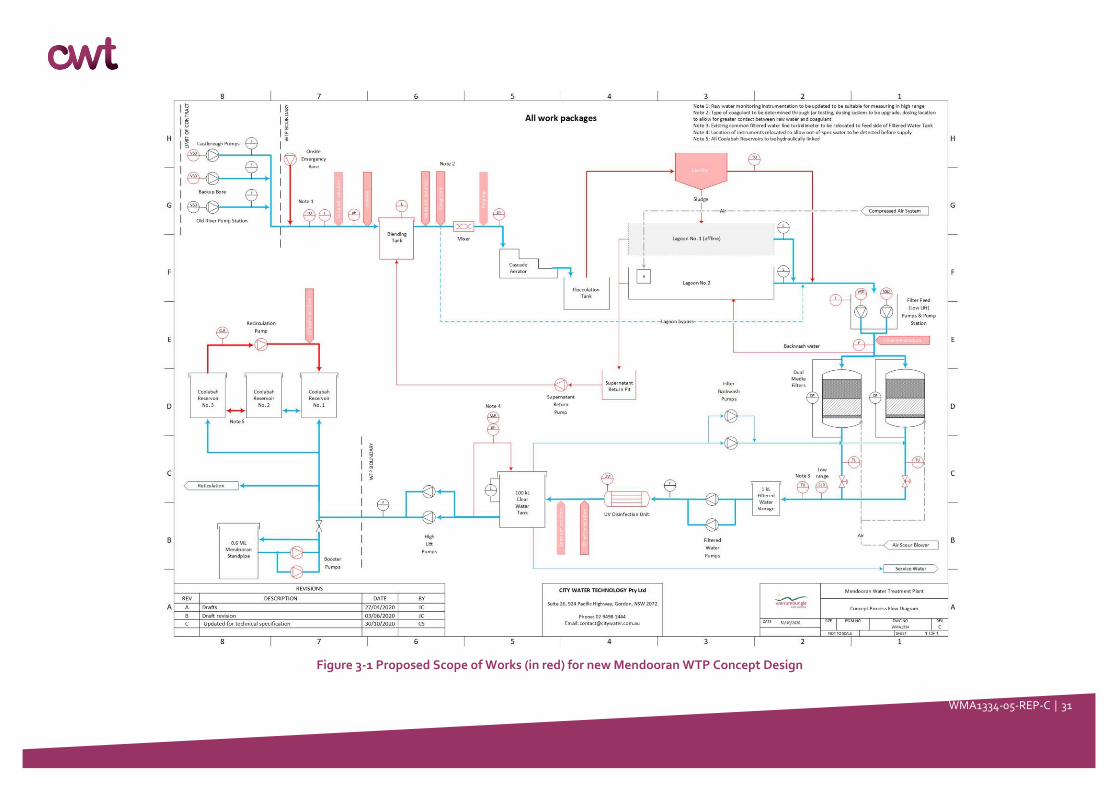
3.6 Process Flow Diagram for Concept Design Scope of Works
Figure 3-1 is process flow diagram illustrates in red all work packages that will be considered in the Concept Design.
WMA1334-05-REP-C │ 31
Figure 3-1 Proposed Scope of Works (in red) for new Mendooran WTP Concept Design
WMA1334-05-REP-C │ 32
4 Design Requirements
To provide a water treatment plant that is robust, effective, reliable, and with a low WHS risk, the following design
considerations shall be addressed in the concept design and/or technical specifications.
4.1 General Considerations
• The concept design acknowledges that the inlet hydraulics of the upgraded WTP must complement the existing
raw water supply hydraulics and pumps.
• The existing WTP is run at a fixed rate in start/ stop mode with some flow reduction via valve throttling. The
concept design shall allow the plant to be downrated and chemical dosing systems to be flow-paced.
• The concept design must allow the WTP to be fully automated and remotely operated based on Supervisory
Control and Data Acquisition (SCADA). Where economic feasibility does not permit such automation, the designer
must make provisions for operator intervention e.g. sample taps, operator adjusted dose rates and laboratory
testing facilities.
• A risk and hazard assessment (HAZOP) of the design is required, with WSC involvement.
• A hazard and critical control point assessment of the design is required, with WSC involvement.
• Existing services or assets to be retained, connected to or refurbished on site are to be taken into consideration
when configuring new process components.
• The existing Mendooran WTP must be operable throughout construction and commissioning.
• It is the Contractor’s responsibility to ensure that provisions are made to ensure new infrastructure is appropriately
secured from public access during construction.
• Chemical delivery access roads and turnaround bays to be constructed should be suitable for the delivery of IBC
chemical dosing systems and equipment and materials replacements as required. WSC would need to liaise with
local suppliers regarding vehicle delivery tonnage.
• Flexibility and redundancy in the design is included, for example multiple chemical dosing points, duty/ standby
dosing pumps with automatic duty changeover, and the ability to take units off-line for maintenance whilst
continuing to operate.
4.2 Process Requirements
4.2.1 Preferred Treatment Process
• Refer to Section 3.2 of this report.
4.2.2 Design Capacities
The existing Mendooran WTP was designed for ~1 ML/d with the Castlereagh Riverbed pumps (main supply) delivering
raw water at an instantaneously flowrate of 14.5 L/s (i.e. 1.15 ML/d extraction for 22 hours of operation).
The plant is oversized with respect to water licencing limits (150 ML/pa from Castlereagh River) as well peak demands.
Oversizing the plant has several disadvantages including, but not limited to:
• Higher capital and operational costs associated with implementation of new equipment sized to 1 ML/d.
• Short plant run times (due to high instantaneous flowrates) leading to more frequent start/stop operation and
consequently, greater opportunity for turbidity spikes.
WMA1334-05-REP-C │ 33
At present, the higher instantaneous rate through the plant (~14.5 L/s) is favoured by Council as it allows the
Mendooran Standpipe to maintain a sufficient volume/head pressure to mitigate low pressure issues in parts of the
reticulation. However, with the implementation of booster pumps at the Standpipe, this requirement will be
redundant.
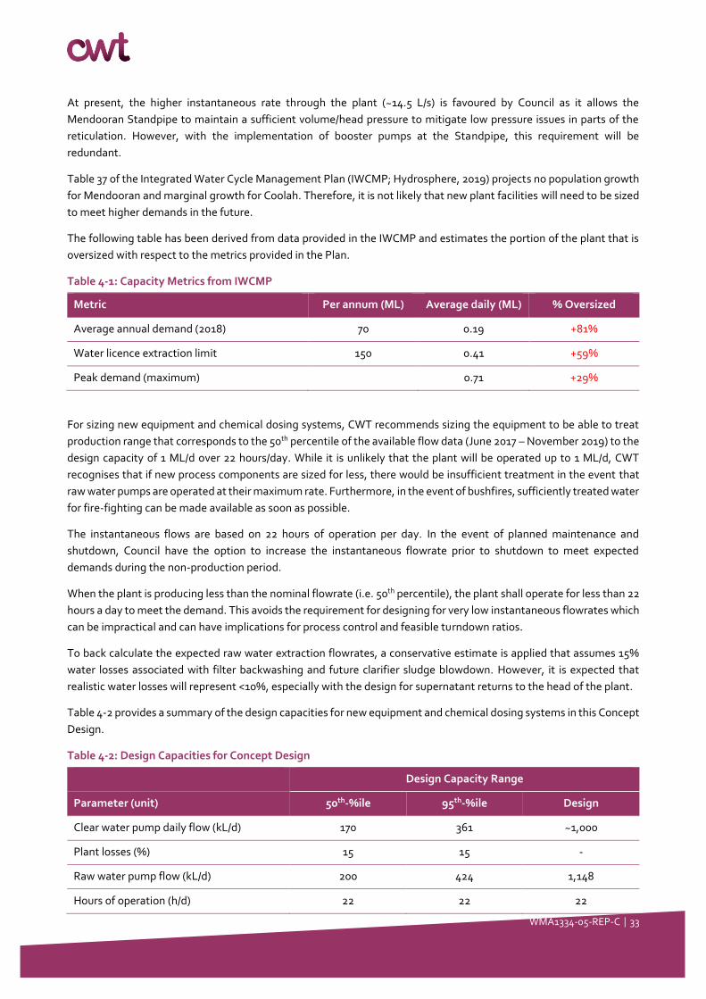
Table 37 of the Integrated Water Cycle Management Plan (IWCMP; Hydrosphere, 2019) projects no population growth
for Mendooran and marginal growth for Coolah. Therefore, it is not likely that new plant facilities will need to be sized
to meet higher demands in the future.
The following table has been derived from data provided in the IWCMP and estimates the portion of the plant that is
oversized with respect to the metrics provided in the Plan.
Table 4-1: Capacity Metrics from IWCMP
Metric Per annum (ML) Average daily (ML) % Oversized
Average annual demand (2018) 70 0.19 +81%
Water licence extraction limit 150 0.41 +59%
Peak demand (maximum) 0.71 +29%
For sizing new equipment and chemical dosing systems, CWT recommends sizing the equipment to be able to treat
production range that corresponds to the 50th percentile of the available flow data (June 2017 – November 2019) to the
design capacity of 1 ML/d over 22 hours/day. While it is unlikely that the plant will be operated up to 1 ML/d, CWT
recognises that if new process components are sized for less, there would be insufficient treatment in the event that
raw water pumps are operated at their maximum rate. Furthermore, in the event of bushfires, sufficiently treated water
for fire-fighting can be made available as soon as possible.
The instantaneous flows are based on 22 hours of operation per day. In the event of planned maintenance and
shutdown, Council have the option to increase the instantaneous flowrate prior to shutdown to meet expected
demands during the non-production period.
When the plant is producing less than the nominal flowrate (i.e. 50th percentile), the plant shall operate for less than 22
hours a day to meet the demand. This avoids the requirement for designing for very low instantaneous flowrates which
can be impractical and can have implications for process control and feasible turndown ratios.
To back calculate the expected raw water extraction flowrates, a conservative estimate is applied that assumes 15%
water losses associated with filter backwashing and future clarifier sludge blowdown. However, it is expected that
realistic water losses will represent <10%, especially with the design for supernatant returns to the head of the plant.
Table 4-2 provides a summary of the design capacities for new equipment and chemical dosing systems in this Concept
Design.
Table 4-2: Design Capacities for Concept Design
Design Capacity Range
Parameter (unit) 50th-%ile 95th-%ile Design
Clear water pump daily flow (kL/d) 170 361 ~1,000
Plant losses (%) 15 15 -
Raw water pump flow (kL/d) 200 424 1,148
Hours of operation (h/d) 22 22 22
WMA1334-05-REP-C │ 34
Design Capacity Range
Parameter (unit) 50th-%ile 95th-%ile Design
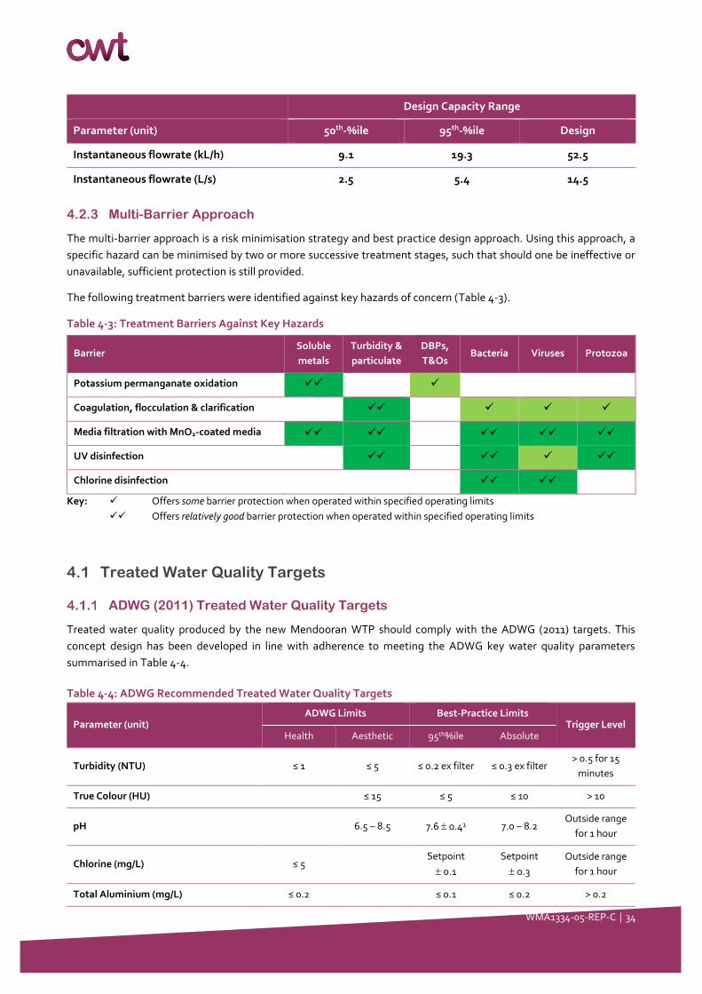
Instantaneous flowrate (kL/h) 9.1 19.3 52.5
Instantaneous flowrate (L/s) 2.5 5.4 14.5
4.2.3 Multi-Barrier Approach
The multi-barrier approach is a risk minimisation strategy and best practice design approach. Using this approach, a
specific hazard can be minimised by two or more successive treatment stages, such that should one be ineffective or
unavailable, sufficient protection is still provided.
The following treatment barriers were identified against key hazards of concern (Table 4-3).
Table 4-3: Treatment Barriers Against Key Hazards
Barrier Soluble
metals
Turbidity &
particulate
DBPs,
T&Os Bacteria Viruses Protozoa
Potassium permanganate oxidation ✓✓ ✓
Coagulation, flocculation & clarification ✓✓ ✓ ✓ ✓
Media filtration with MnO2-coated media ✓✓ ✓✓ ✓✓ ✓✓ ✓✓
UV disinfection ✓✓ ✓✓ ✓ ✓✓
Chlorine disinfection ✓✓ ✓✓
Key: ✓ Offers some barrier protection when operated within specified operating limits
✓✓ Offers relatively good barrier protection when operated within specified operating limits
4.1 Treated Water Quality Targets
ADWG (2011) Treated Water Quality Targets
Treated water quality produced by the new Mendooran WTP should comply with the ADWG (2011) targets. This
concept design has been developed in line with adherence to meeting the ADWG key water quality parameters
summarised in Table 4-4.
Table 4-4: ADWG Recommended Treated Water Quality Targets
Parameter (unit) ADWG Limits Best-Practice Limits
Trigger Level Health Aesthetic 95th%ile Absolute
Turbidity (NTU) ≤ 1 ≤ 5 ≤ 0.2 ex filter ≤ 0.3 ex filter > 0.5 for 15
minutes
True Colour (HU) ≤ 15 ≤ 5 ≤ 10 > 10
pH 6.5 – 8.5 7.6 0.41 7.0 – 8.2 Outside range
for 1 hour
Chlorine (mg/L) ≤ 5 Setpoint
0.1
Setpoint
0.3
Outside range
for 1 hour
Total Aluminium (mg/L) ≤ 0.2 ≤ 0.1 ≤ 0.2 > 0.2
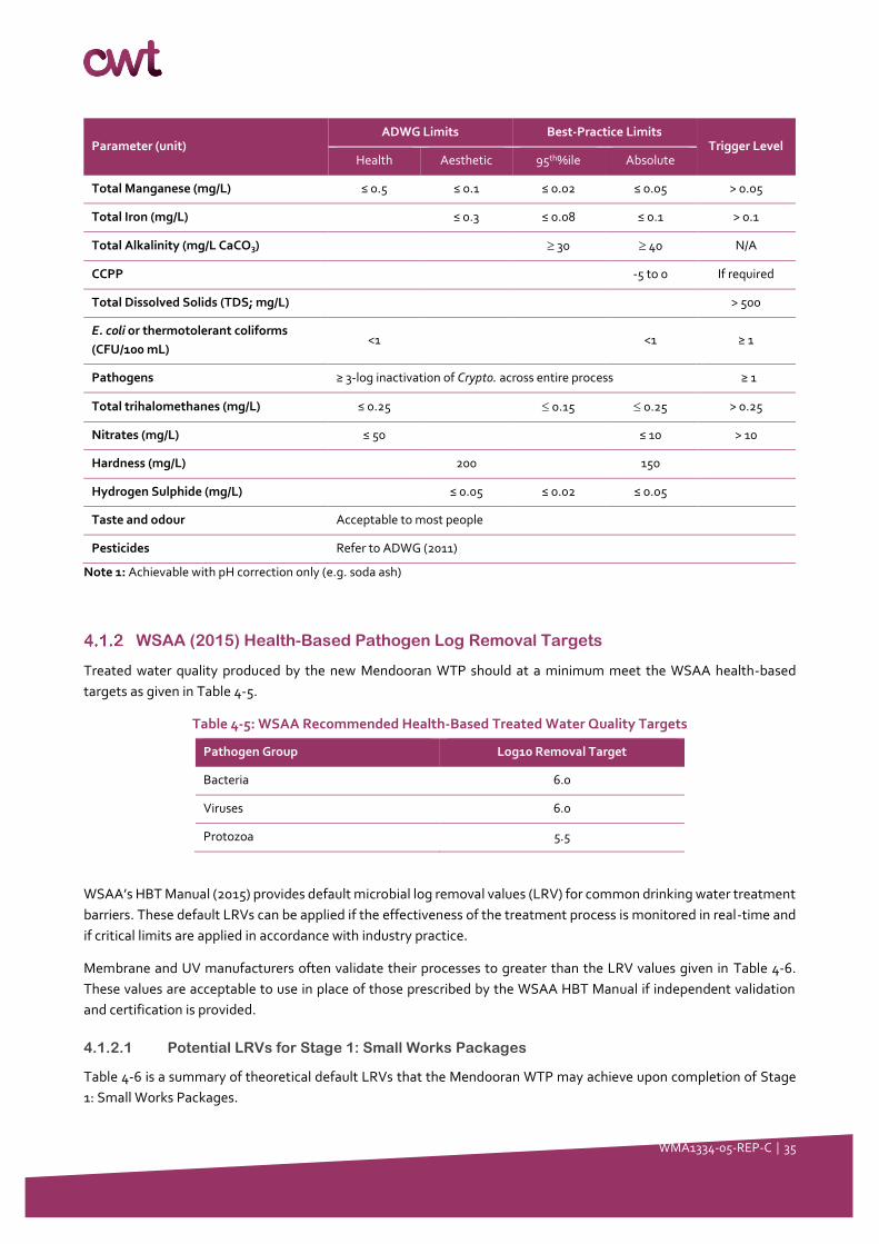
WMA1334-05-REP-C │ 35
Parameter (unit) ADWG Limits Best-Practice Limits
Trigger Level Health Aesthetic 95th%ile Absolute
Total Manganese (mg/L) ≤ 0.5 ≤ 0.1 ≤ 0.02 ≤ 0.05 > 0.05
Total Iron (mg/L) ≤ 0.3 ≤ 0.08 ≤ 0.1 > 0.1
Total Alkalinity (mg/L CaCO3) 30 40 N/A
CCPP -5 to 0 If required
Total Dissolved Solids (TDS; mg/L) > 500
E. coli or thermotolerant coliforms
(CFU/100 mL) <1 <1 ≥ 1
Pathogens ≥ 3-log inactivation of Crypto. across entire process ≥ 1
Total trihalomethanes (mg/L) ≤ 0.25 0.15 0.25 > 0.25
Nitrates (mg/L) ≤ 50 ≤ 10 > 10
Hardness (mg/L) 200 150
Hydrogen Sulphide (mg/L) ≤ 0.05 ≤ 0.02 ≤ 0.05
Taste and odour Acceptable to most people
Pesticides Refer to ADWG (2011)
Note 1: Achievable with pH correction only (e.g. soda ash)
WSAA (2015) Health-Based Pathogen Log Removal Targets
Treated water quality produced by the new Mendooran WTP should at a minimum meet the WSAA health-based
targets as given in Table 4-5.
Table 4-5: WSAA Recommended Health-Based Treated Water Quality Targets
Pathogen Group Log10 Removal Target
Bacteria 6.0
Viruses 6.0
Protozoa 5.5
WSAA’s HBT Manual (2015) provides default microbial log removal values (LRV) for common drinking water treatment
barriers. These default LRVs can be applied if the effectiveness of the treatment process is monitored in real-time and
if critical limits are applied in accordance with industry practice.
Membrane and UV manufacturers often validate their processes to greater than the LRV values given in Table 4-6.
These values are acceptable to use in place of those prescribed by the WSAA HBT Manual if independent validation
and certification is provided.
4.1.2.1 Potential LRVs for Stage 1: Small Works Packages
Table 4-6 is a summary of theoretical default LRVs that the Mendooran WTP may achieve upon completion of Stage
1: Small Works Packages.

WMA1334-05-REP-C │ 36
Table 4-6: Theoretical Log Reduction Capacity of Stage 1 Mendooran WTP
Treatment Barrier
Default LRV Manual Critical Limits
Bacteria Virus Protozoa
Conventional Treatment
(coagulation, flocculation,
sedimentation and granular
filtration)
2.0 2.0 3.0
Individual treated water turbidity ≤0.3 NTU for 95% of
the month and not >0.5 NTU for ≥15 consecutive
minutes.
Chlorine Disinfection 4.0 4.0 0
C.t. will vary depending on the log removal required and
the temperature, turbidity and pH of the water.
Typically, the C.t. will be greater than 15 mg.min/L.
Total LRV capacity 6.0 6.0 3.0
Health-Based Target 6.0 6.0 5.5
LRV credit or deficit +0 +0 -2.5 Assuming critical limits (above) are not exceeded
Even if the Stage 1 upgraded Mendooran WTP meets the water quality objectives for their treatment processes defined
in Table 4-6, the WTP would not meet its HBT for protozoa.
4.1.2.2 Potential LRVs for Stage 2: Additional Work Packages
Table 4-6 is a summary of theoretical default LRVs that the Mendooran WTP may achieve upon completion of stage 2:
Additional Work Packages.
Table 4-7: Theoretical Log Reduction Capacity of Stage 2 Mendooran WTP
Treatment Barrier
Default LRV Manual Critical Limits
Bacteria Virus Protozoa
Conventional Treatment
(coagulation,
flocculation,
sedimentation and
granular filtration)
2.0 2.0 3.0 Individual filter turbidity ≤ 0.3 NTU for 95% of month and
not > 0.5 NTU for ≥ 15 consecutive minutes.
Chlorine Disinfection 4.0 4.0 0
C.t. will vary depending on the log removal required and
the temperature, turbidity and pH of the water. Typically,
the C.t. will be greater than 16 mg.min/L.
UV Disinfection 4.0 0.5 4.0
UV dose > 40 mJ/cm2
Feed water <1 NTU
UVT% > manufacturer’s specifications
Total LRV capacity 10.0 6.5 7.0
Health-Based Target 6.0 6.0 5.5
LRV credit or deficit +4.0 +0.5 +1.5 Assuming critical limits (above) are not exceeded
If Stage 2 upgraded Mendooran WTP meets the water quality objectives for their treatment processes defined in Table
4-7, the WTP could theoretically meets its HBTs.

WMA1334-05-REP-C │ 37
4.2 Buildings
• New chlorine gas rooms are to be built in accordance with AS/NZS 2927: The Storage and Handling of Liquefied
Chlorine Gas at two (2) sites:
Mendooran WTP site located on Lot DP 1076077
Coolabah Reservoir site located on Lot DP 717238.
• No other new buildings are included in the scope of works.
• However, consideration is made for WHS and safety equipment and modifications to existing infrastructure will
be included as required e.g. modifications to bunds.
4.3 Power Supply
• Power is available at each of the three sites: WTP site at Lot DP 1076077, Mendooran Standpipe site at Lot #N/A
and Coolabah Reservoir site at Lot DP 717238.
• Additional power supply requirements are to be determined by WSC. WSC will be responsible for providing
sufficient power for connection by the Contractor.
4.4 Telemetry and Control Systems
• The control system is to be linked to the raw water supply pumps to enable automatic start-up where possible.
• The control system may incorporate:
A hot backup computer control system
Continuous monitoring
Remote access and control
Automatic adjustment of all dosing rates based on monitoring (parameters and feedback loops to be
determined)
Flow pacing, with no hunting or rapid changes to dosing or flowrates
Calibration testing ability
A manual override facility.
• Telemetry and communications are available at site. The Contractor is to connect and/or interface with the existing
telemetry and communications utilities available at site. The Contractor shall make an assessment for any
necessary augmentations to the existing system.
• Any additional telemetry and communication requirements are to be determined by WSC.
4.5 Documentation
The following documentation should be provided by the Contractor:
• Operation and maintenance manuals
• Functional description
• Equipment supplier manuals
• As built drawings
WMA1334-05-REP-C │ 38
• Piping and instrument diagram
• Calibration certificates
• Commissioning checklists (FAT / SAT)
• Proof of Performance (PoP) Test Plan
• PoP outcomes report and supporting evidence
• Safe work method statements
• Standard operating procedures
• Equipment schedules
• I/O list
• PLC code
• Alarm list.
4.6 Training
Upon commissioning each Stage of works, the Contractor shall provide training to ensure operators are appropriately
trained to operate and maintain the installations.
Operator training should include:
• Operating principles
• Routine operation
• Routine maintenance (calibration, cleaning, etc.)
• Jar testing
• Troubleshooting
• Safety considerations
• Environment considerations.
It is Council’s preference that training is carried after commissioning of each stage of works for a minimum of one (1)
working day.
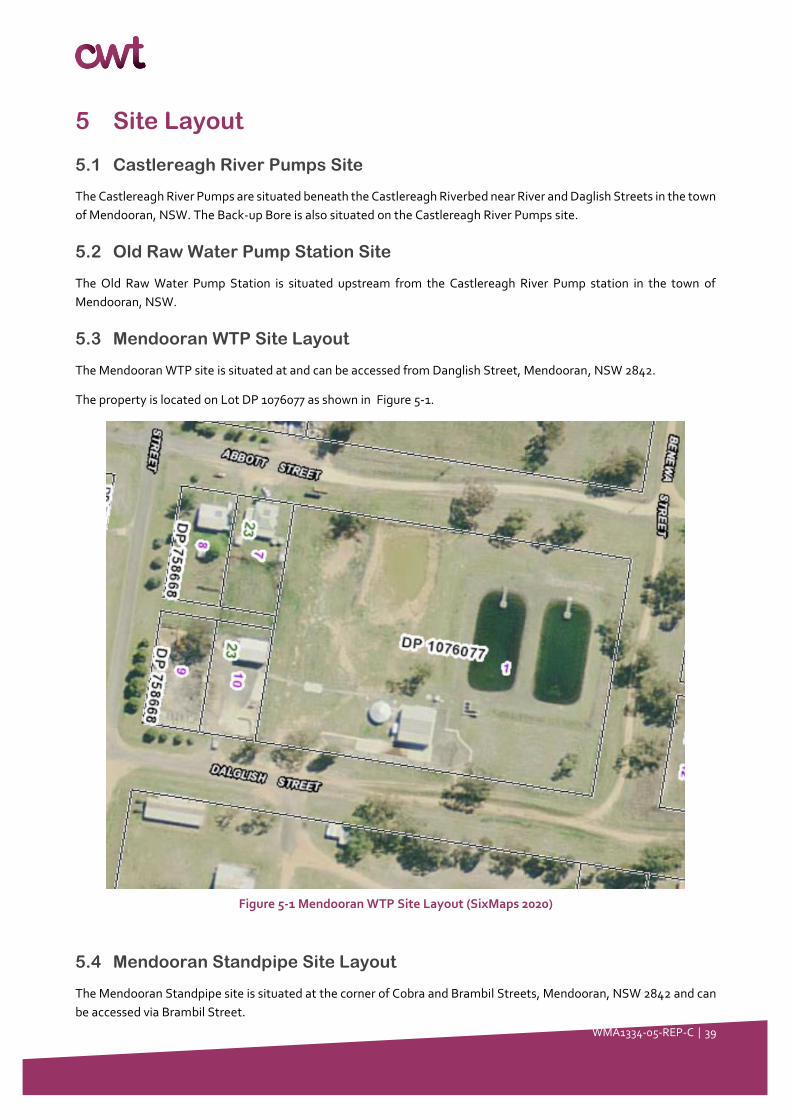
WMA1334-05-REP-C │ 39
5 Site Layout
5.1 Castlereagh River Pumps Site
The Castlereagh River Pumps are situated beneath the Castlereagh Riverbed near River and Daglish Streets in the town
of Mendooran, NSW. The Back-up Bore is also situated on the Castlereagh River Pumps site.
5.2 Old Raw Water Pump Station Site
The Old Raw Water Pump Station is situated upstream from the Castlereagh River Pump station in the town of
Mendooran, NSW.
5.3 Mendooran WTP Site Layout
The Mendooran WTP site is situated at and can be accessed from Danglish Street, Mendooran, NSW 2842.
The property is located on Lot DP 1076077 as shown in Figure 5-1.
Figure 5-1 Mendooran WTP Site Layout (SixMaps 2020)
5.4 Mendooran Standpipe Site Layout
The Mendooran Standpipe site is situated at the corner of Cobra and Brambil Streets, Mendooran, NSW 2842 and can
be accessed via Brambil Street.
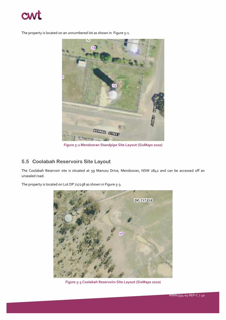
WMA1334-05-REP-C │ 40
The property is located on an unnumbered lot as shown in Figure 5-1.
Figure 5-2 Mendooran Standpipe Site Layout (SixMaps 2020)
5.5 Coolabah Reservoirs Site Layout
The Coolabah Reservoir site is situated at 59 Manusu Drive, Mendooran, NSW 2842 and can be accessed off an
unsealed road.
The property is located on Lot DP 717238 as shown in Figure 5-3.
Figure 5-3 Coolabah Reservoirs Site Layout (SixMaps 2020)

WMA1334-05-REP-C │ 41
6 Work Package 1: Raw Water Supply and Blending
6.1 Description of works
6.1.1 Overview
The following table is an excerpt of Table 3-1, and summarises the activities to be addressed in this Section of the
Report.
Table 6-1: Work Package 1 - Scope of Works and Activities
No. Work packages Activities
WP1 Raw water supply and
blending
• Concept design and description of:
o Connection of Emergency Onsite Bore to common inlet main
o Raw water blending philosophy (subject to water quality data
availability)
o Installation of a new Blending Tank
6.1.2 Process Description
The raw water source to Mendooran WTP shall be selected by the operator in the PLC. Raw water is primarily sourced
from the Castlereagh River Pumps. A Backup Bore is also available adjacent to the Castlereagh River Pumps. The Old
Raw Water Pump Station designated as an alternate water supply during periods of low flow. Each supply line is
equipped with a flowmeter before connecting to the raw water main which extends to the Mendooran WTP.
Within the WTP site boundary, a newly configured T-connection shall provide supply from the Onsite Emergency Bore
if elected to run.
The Castlereagh River Pumps, Backup Bore, Old River Pump Station and Emergency Onsite Bore can be operated
concurrently to improve raw water availability. However, the total combined raw water flowrate received at the plant
shall not exceed 14.5 L/s to prevent over-pressurising the main and/or overwhelming the plant treatment processes.
Each raw water pump, except for the Onsite Emergency Bore Pump is to be equipped with variable speed drives to
allow the plant to be downrated to extend run-times while meeting treated water demands. Downrating the plant will
have significant impact on improved water quality.
After the T-section, the raw water pH and turbidity shall be measured online before passing through a common raw
water flow meter.
Prior to being received at a newly installed Blending Tank, soda ash for pH and alkalinity adjustment (optional), and
potassium permanganate for soluble metals oxidation, shall be flow-paced to the raw water flowrate as measured by
the common raw water flowmeter.
The Blending Tank shall facilitate blending of raw water received from alternating sources and supernatant returns
(future) as well as sufficient contact time for potassium permanganate dosing. In the future (stage 2), a supernatant
return pump shall return supernatant from converted Sedimentation Lagoons (to Sludge Lagoons) to the Blending
Tank, to allow dilution of supernatant with raw water and enable contact with the downstream coagulation process.
The Blending Tank shall be fitted with a level transmitter for the stop/ start signals of the selected Raw Water Pump(s).
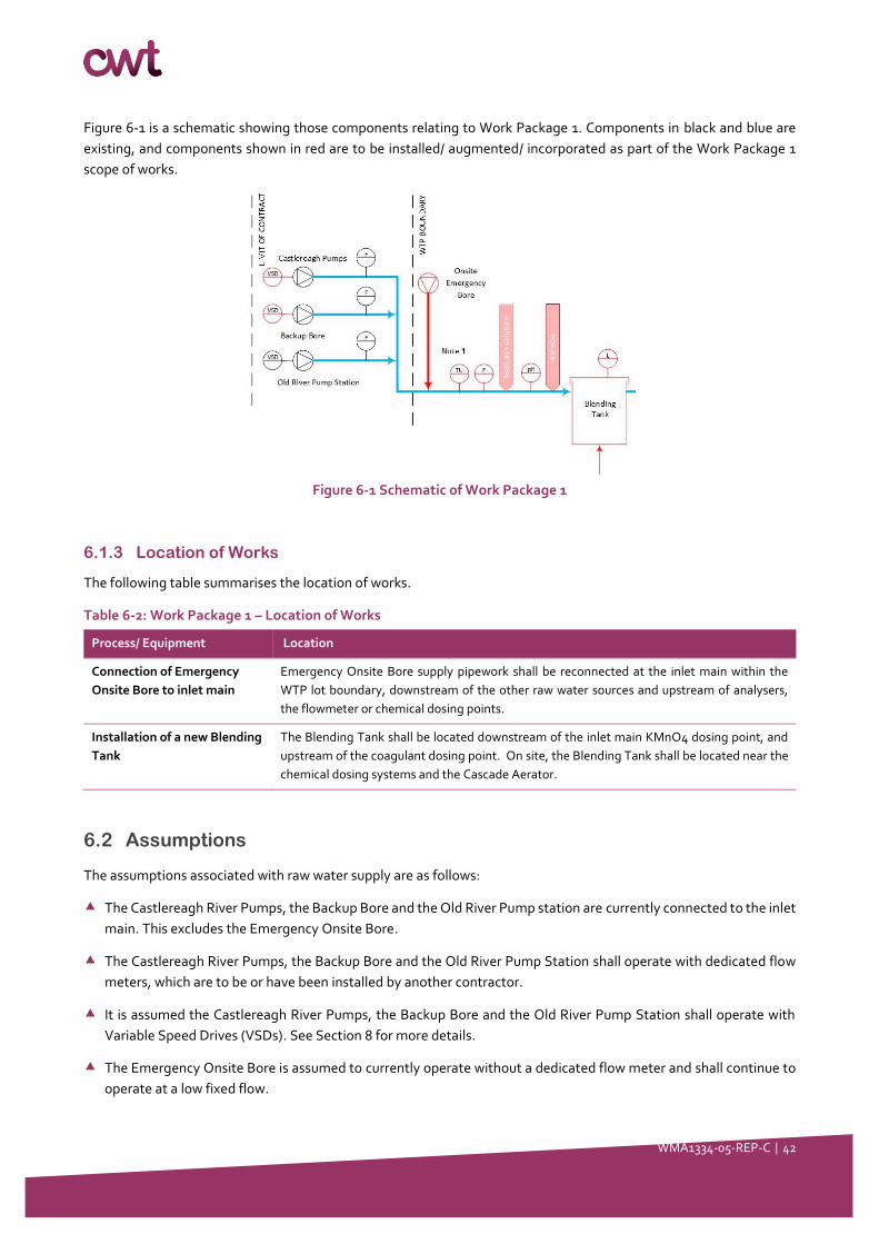
WMA1334-05-REP-C │ 42
Figure 6-1 is a schematic showing those components relating to Work Package 1. Components in black and blue are
existing, and components shown in red are to be installed/ augmented/ incorporated as part of the Work Package 1
scope of works.
Figure 6-1 Schematic of Work Package 1
6.1.3 Location of Works
The following table summarises the location of works.
Table 6-2: Work Package 1 – Location of Works
Process/ Equipment Location
Connection of Emergency
Onsite Bore to inlet main
Emergency Onsite Bore supply pipework shall be reconnected at the inlet main within the
WTP lot boundary, downstream of the other raw water sources and upstream of analysers,
the flowmeter or chemical dosing points.
Installation of a new Blending
Tank
The Blending Tank shall be located downstream of the inlet main KMnO4 dosing point, and
upstream of the coagulant dosing point. On site, the Blending Tank shall be located near the
chemical dosing systems and the Cascade Aerator.
6.2 Assumptions
The assumptions associated with raw water supply are as follows:
The Castlereagh River Pumps, the Backup Bore and the Old River Pump station are currently connected to the inlet
main. This excludes the Emergency Onsite Bore.
The Castlereagh River Pumps, the Backup Bore and the Old River Pump Station shall operate with dedicated flow
meters, which are to be or have been installed by another contractor.
It is assumed the Castlereagh River Pumps, the Backup Bore and the Old River Pump Station shall operate with
Variable Speed Drives (VSDs). See Section 8 for more details.
The Emergency Onsite Bore is assumed to currently operate without a dedicated flow meter and shall continue to
operate at a low fixed flow.
WMA1334-05-REP-C │ 43
The Castlereagh River Pumps, Backup Bore, Old River Pump Station and Emergency Onsite Bore can be operated
concurrently to improve raw water availability. However, the total combined raw water flowrate received at the
plant shall not exceed 14.5 L/s to prevent over-pressurising the main and/or overwhelming the plant treatment
processes.
6.3 Design Requirements
6.3.1 Raw Water Supply
The design requirements for raw water supply are as follows:
To match raw water flow and treated water demand, all pumps except the Emergency Onsite Bore require VSDs.
The Emergency Onsite Bore is an exception as it does not provide enough flow to validate the use of a VSD. The
details of the VSD instrumentation are listed in Section 8.
The raw water sources and the flow rates, within the capacity range outlined in Section 4.2.2, shall be operator
selectable.
The Castlereagh River Pumps, Backup Bore, Old River Pump Station and Emergency Onsite Bore can be operated
concurrently but must not exceed a combined raw water flowrate of 14.5 L/s as measured by the combined raw
water flowmeter.
The Emergency Onsite Bore pipework shall be modified to connect to the common inlet main upstream of
instruments and chemical dose points. See assumptions below.
Flow and analytic instrumentation will be provided, with details outlined in Section 8.
The inlet works shall be designed to accommodate the inline dosing of potassium permanganate and soda ash. The
details of the chemical dosing systems are listed in Section 7.
The dosing point for potassium permanganate shall be located downstream of the mains intersection from any raw
water pumps or raw water quality instrumentation.
The dosing point for soda ash shall be located downstream of the mains intersection from any raw water pumps or
raw water quality instrumentation and shall be located upstream of the potassium permanganate dosing point.
The raw water main shall be connected to the new Blending Tank.
6.3.2 Blending Tank
The design requirements for Blending Tank are as follows:
• Existing plant hydraulics i.e. sized for the maximum flow of 1.148 ML/d over 22 hours.
• 5-15 minutes contact time for oxidation of soluble metals by upstream dosing of potassium permanganate
• An appropriately designed inlet, outlet and/or baffles to prevent short-circuiting so that the effective contact time
is achieved i.e. baffle factor of 0.3
• The Blending Tank is to be sized with respect to:
Hydraulic requirements
5 - 10% supernatant returns
• Suitable materials of construction to be compliant with potassium permanganate dosing
• Level sensors for the stop/ start of the WTP.
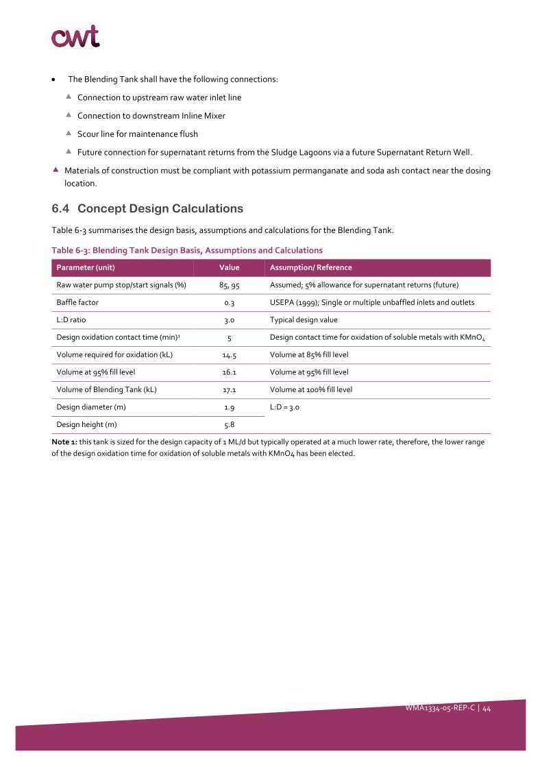
WMA1334-05-REP-C │ 44
• The Blending Tank shall have the following connections:
Connection to upstream raw water inlet line
Connection to downstream Inline Mixer
Scour line for maintenance flush
Future connection for supernatant returns from the Sludge Lagoons via a future Supernatant Return Well.
Materials of construction must be compliant with potassium permanganate and soda ash contact near the dosing
location.
6.4 Concept Design Calculations
Table 6-3 summarises the design basis, assumptions and calculations for the Blending Tank.
Table 6-3: Blending Tank Design Basis, Assumptions and Calculations
Parameter (unit) Value Assumption/ Reference
Raw water pump stop/start signals (%) 85, 95 Assumed; 5% allowance for supernatant returns (future)
Baffle factor 0.3 USEPA (1999); Single or multiple unbaffled inlets and outlets
L:D ratio 3.0 Typical design value
Design oxidation contact time (min)1 5 Design contact time for oxidation of soluble metals with KMnO4
Volume required for oxidation (kL) 14.5 Volume at 85% fill level
Volume at 95% fill level 16.1 Volume at 95% fill level
Volume of Blending Tank (kL) 17.1 Volume at 100% fill level
Design diameter (m) 1.9 L:D = 3.0
Design height (m) 5.8
Note 1: this tank is sized for the design capacity of 1 ML/d but typically operated at a much lower rate, therefore, the lower range
of the design oxidation time for oxidation of soluble metals with KMnO4 has been elected.

WMA1334-05-REP-C │ 45
7 Work Package 2: Chemical Dosing Facilities
7.1 Description of works
7.1.1 Overview
The following table is an excerpt of Table 3-1 is summarises the activities to be addressed in this Section of the Report.
Table 7-1: Scope of Works and Activities
No. Work packages Activities
WP2 Chemical
dosing facilities
upgrades
• Concept design and description for each chemical dosing systems (soda ash, potassium
permanganate, polyaluminium chloride, polymer LT22S and chlorine gas) with
consideration for:
o Delivery (to site) and loading
o Batching, mixing and storage
o Delivery (to process)
o Dosing location
o WHS incl. PPE and safety equipment
o Relevant standards.
• Installation of an inline mixer
• Upgrade of service water pumps
• Installation of a Wastewater Holding Tank
7.1.2 Process Description
The following table summarises the purpose for each work activity which is addressed in this Section of the report.
Table 7-2: Chemicals and Purpose
Chemical Dosing Location Purpose
Soda Ash Primary dose point (optional): On the combined raw
water line at the inlet to the Blending Tank and prior
to potassium permanganate dosing.
To raise pH to meet target pH setpoint for optimal
oxidation with potassium permanganate. Potassium
permanganate is most effective at pH 8.5.
Secondary dose point (optional): At the outlet of the
Blending Tank prior to coagulant dosing.
If required, to adjust pH to meet a target pH setpoint
for optimal coagulation; typically 7.0 – 8.0. However,
PACl coagulant is not highly pH dependant.
Tertiary dose point (optional): Downstream of
chlorine dosing point for disinfection and prior to the
Clear Water Tank
If required, to adjust pH to meet a target pH setpoint
for optimal corrosion control; typically 7.6 to 7.8.
Potassium
Permanganate
(KMnO4)
On the combined raw water line at the inlet to the
Blending Tank and after primary soda ash dosing.
For the oxidation of soluble metals; particularly
manganese and iron.
Poly-
Aluminium
Chloride
(PACl)
At the outlet of the Blending Tank, after the
secondary soda ash dosing point and prior to the
inline mixer.
To form floc for the removal of dissolved organic
matter and colloidal particles through sedimentation.

WMA1334-05-REP-C │ 46
Chemical Dosing Location Purpose
Cationic
Polymer
LT22S
At the juncture between the existing Cascade Aerator
and prior to the Flocculation Tank
To act as a flocculation aid and facilitate in the
coagulation of floc.
Chlorine Gas Oxidation: At the inlet to the Media Filters on the
common filter feed line
To catalyse the formation of manganese oxide-
coated media within the filter media bed for
secondary oxidation of soluble metals; manganese
and iron.
Also establishes an oxidation barrier for manganese
removal in the event of KMnO4 overdosing or
destratification in the Sedimentation Lagoons
leading to leaching of metals.
Disinfection: After UV Disinfection Unit and prior to
soda ash dosing and Clear Water Tank.
Disinfection for inactivation of chlorine-sensitive
pathogens; particularly bacteria and viruses
Booster chlorination: At the Coolabah Reservoir
Recirculation Line
Booster chlorination to booster chlorination to
replace any chlorine lost due to water age to meet
chlorine residual setpoint as required.
Inline Mixer To ensure sufficient chemical dispersion, mixing and
contact with volume of water.
Service Water
Pumps
- To provide sufficient service water for chemical
dosing batching, dilution and/or carrier water as well
as services for hose-down etc.
Waste Holding
Tank
- For the collection chemicals not suitable for disposal
to the environment or for recycle to the head of works
such as chemical spills.
7.1.3 Location of works
The following table summarises the location of works.
Table 7-3: Location of Works
Work Packages Location of Works
Soda Ash Dosing Facility To be installed within the existing Chemical Storage Building with dosing lines extending to
the appropriate dose points in the process as described in Table 7-2 above. KMnO4 Dosing Facility
PACl Dosing Facility
Polymer LT22S Dosing
Facility
Chlorine Gas Dosing Facility Mendooran WTP site: To be installed in separate and potentially adjoining Chlorine Gas
Dosing Room
Coolabah Reservoirs’ site: To be installed in a newly construction Chlorine Gas Dosing Room
Inline Mixer To be installed in proximity to the chemical dosing systems, Blending Tank and Cascade
Aerator.

WMA1334-05-REP-C │ 47
Work Packages Location of Works
Service Water Pumps To be installed on the service water supply line extending from existing Clear Water Tank and
supplying each chemical dosing facility (except the chlorine gas dosing facility) and Service
Water taps and hoses.
Waste Holding Tank To be installed at a location to be determined by the Contractor
7.2 Design Requirements
7.2.1 Design Basis
A number of design bases have been applied to determine the chemical dosing and storage requirements for the
upgraded Mendooran WTP:
• The coagulant dosing system shall have at least 30 days’ storage volume at average dose and average flowrate
• Sufficient capacity of all systems will allow at least three days unattended operation
• The soda ash dosing system shall include a softener to prevent scaling
• Liquid dosing systems will be fitted with pulsation dampeners and local calibration tubes
• Relevant chemical systems and unloading areas will be suitably bunded to contain the chemical in the event of
spillage
• All chemical dosing lines with be laid in chemical trenches or trays where appropriate. The trenches will be covered
with removable covers
• All chemical dosing lines will be appropriately labelled identifying the chemical in the line, the direction of flow and
marked with appropriate colours (in accordance with WSC’s elected standards)
• All equipment (including injection equipment and dosing lines) will allow for easy and safe isolation, to facilitate
quick repairs without necessitating shutdown of the plant
• Service water pumps shall be sized to permit all chemicals to be adequately diluted prior to dosing to improve
mixing:
Soda ash shall be:
▪ Batched as a 10% w/v solution
▪ Delivered at a 10:1 ratio of carrier water to soda ash solution
Potassium permanganate shall be:
▪ Batched as a 2% w/v solution. Note: this is an estimate based on previous experience. Solubility can
vary depending on mixing efficacy and temperature.
▪ Delivered at a 10:1 ratio of carrier water to potassium permanganate slurry
Polymer LT22S shall be:
▪ Batched as a 0.2% w/v solution (typically 0.15-0.3%)
▪ Delivered at a 10:1 ratio of carrier water to polymer solution
Coagulant PACl shall be delivered as at a 20:1 ratio of carrier water to coagulant
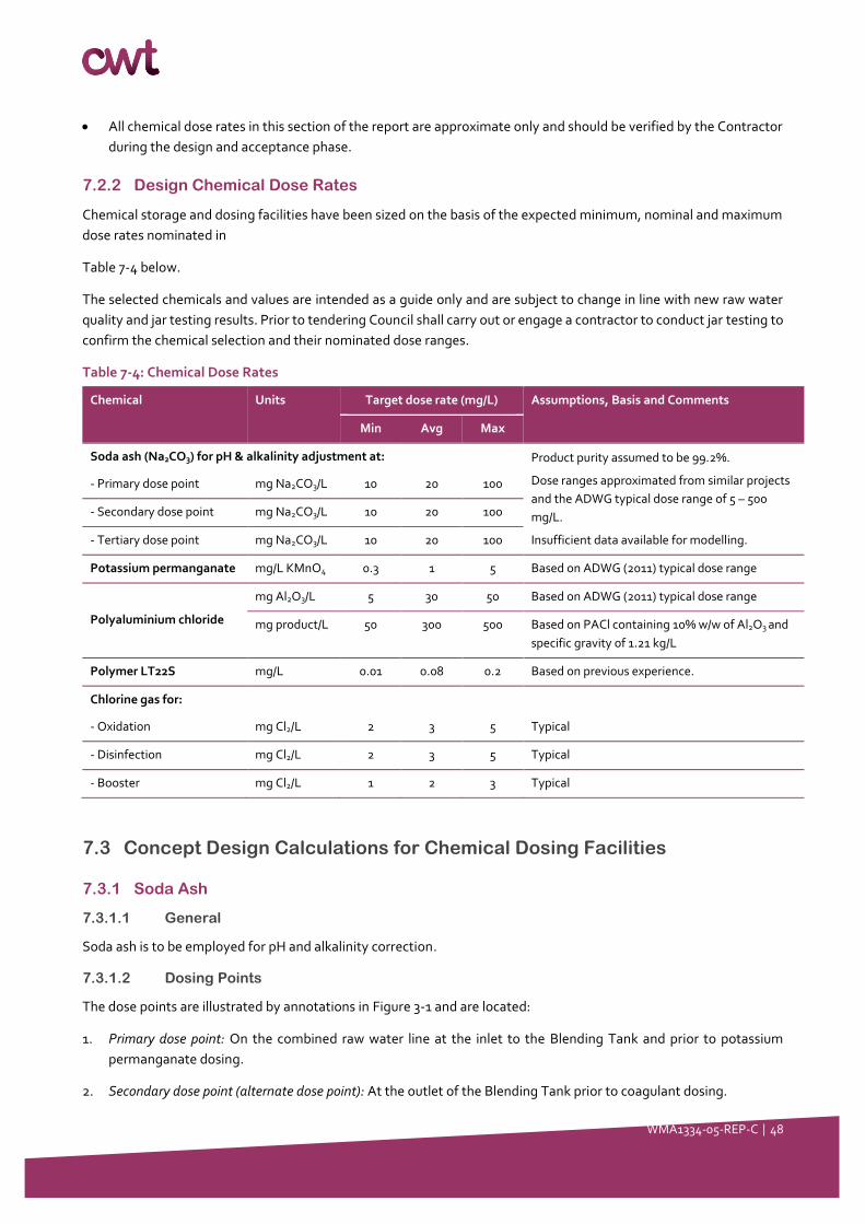
WMA1334-05-REP-C │ 48
• All chemical dose rates in this section of the report are approximate only and should be verified by the Contractor
during the design and acceptance phase.
7.2.2 Design Chemical Dose Rates
Chemical storage and dosing facilities have been sized on the basis of the expected minimum, nominal and maximum
dose rates nominated in
Table 7-4 below.
The selected chemicals and values are intended as a guide only and are subject to change in line with new raw water
quality and jar testing results. Prior to tendering Council shall carry out or engage a contractor to conduct jar testing to
confirm the chemical selection and their nominated dose ranges.
Table 7-4: Chemical Dose Rates
Chemical Units Target dose rate (mg/L) Assumptions, Basis and Comments
Min Avg Max
Soda ash (Na2CO3) for pH & alkalinity adjustment at: Product purity assumed to be 99.2%.
Dose ranges approximated from similar projects
and the ADWG typical dose range of 5 – 500
mg/L.
Insufficient data available for modelling.
- Primary dose point mg Na2CO3/L 10 20 100
- Secondary dose point mg Na2CO3/L 10 20 100
- Tertiary dose point mg Na2CO3/L 10 20 100
Potassium permanganate mg/L KMnO4 0.3 1 5 Based on ADWG (2011) typical dose range
Polyaluminium chloride
mg Al2O3/L 5 30 50 Based on ADWG (2011) typical dose range
mg product/L 50 300 500 Based on PACl containing 10% w/w of Al2O3 and
specific gravity of 1.21 kg/L
Polymer LT22S mg/L 0.01 0.08 0.2 Based on previous experience.
Chlorine gas for:
- Oxidation mg Cl2/L 2 3 5 Typical
- Disinfection mg Cl2/L 2 3 5 Typical
- Booster mg Cl2/L 1 2 3 Typical
7.3 Concept Design Calculations for Chemical Dosing Facilities
7.3.1 Soda Ash
7.3.1.1 General
Soda ash is to be employed for pH and alkalinity correction.
7.3.1.2 Dosing Points
The dose points are illustrated by annotations in Figure 3-1 and are located:
1. Primary dose point: On the combined raw water line at the inlet to the Blending Tank and prior to potassium
permanganate dosing.
2. Secondary dose point (alternate dose point): At the outlet of the Blending Tank prior to coagulant dosing.
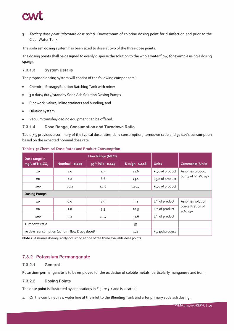
WMA1334-05-REP-C │ 49
3. Tertiary dose point (alternate dose point): Downstream of chlorine dosing point for disinfection and prior to the
Clear Water Tank
The soda ash dosing system has been sized to dose at two of the three dose points.
The dosing points shall be designed to evenly disperse the solution to the whole water flow, for example using a dosing
sparge.
7.3.1.3 System Details
The proposed dosing system will consist of the following components:
• Chemical Storage/Solution Batching Tank with mixer
• 3 × duty/ duty/ standby Soda Ash Solution Dosing Pumps
• Pipework, valves, inline strainers and bunding; and
• Dilution system.
• Vacuum transfer/loading equipment can be offered.
7.3.1.4 Dose Range, Consumption and Turndown Ratio
Table 7-5 provides a summary of the typical dose rates, daily consumption, turndown ratio and 30 day’s consumption
based on the expected nominal dose rate.
Table 7-5: Chemical Dose Rates and Product Consumption
Dose range in
mg/L of Na2CO3
Flow Range (ML/d)
Units Comments/ Units Nominal – 0.200 95th-%ile - 0.424 Design - 1.148
10 2.0 4.3 11.6 kg/d of product Assumes product
purity of 99.2% w/v 20 4.0 8.6 23.1 kg/d of product
100 20.2 42.8 115.7 kg/d of product
Dosing Pumps
10 0.9 1.9 5.3 L/h of product Assumes solution
concentration of
10% w/v 20 1.8 3.9 10.5 L/h of product
100 9.2 19.4 52.6 L/h of product
Turndown ratio 57
30 days’ consumption (at nom. flow & avg dose)1 121 kg/30d product
Note 1: Assumes dosing is only occurring at one of the three available dose points.
7.3.2 Potassium Permanganate
7.3.2.1 General
Potassium permanganate is to be employed for the oxidation of soluble metals, particularly manganese and iron.
7.3.2.2 Dosing Points
The dose point is illustrated by annotations in Figure 3-1 and is located:
1. On the combined raw water line at the inlet to the Blending Tank and after primary soda ash dosing.
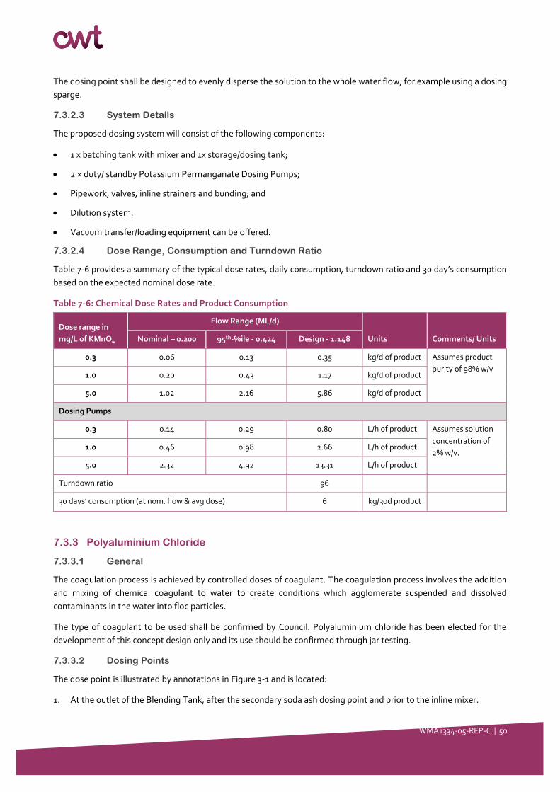
WMA1334-05-REP-C │ 50
The dosing point shall be designed to evenly disperse the solution to the whole water flow, for example using a dosing
sparge.
7.3.2.3 System Details
The proposed dosing system will consist of the following components:
• 1 x batching tank with mixer and 1x storage/dosing tank;
• 2 × duty/ standby Potassium Permanganate Dosing Pumps;
• Pipework, valves, inline strainers and bunding; and
• Dilution system.
• Vacuum transfer/loading equipment can be offered.
7.3.2.4 Dose Range, Consumption and Turndown Ratio
Table 7-6 provides a summary of the typical dose rates, daily consumption, turndown ratio and 30 day’s consumption
based on the expected nominal dose rate.
Table 7-6: Chemical Dose Rates and Product Consumption
Dose range in
mg/L of KMnO4
Flow Range (ML/d)
Units Comments/ Units Nominal – 0.200 95th-%ile - 0.424 Design - 1.148
0.3 0.06 0.13 0.35 kg/d of product Assumes product
purity of 98% w/v 1.0 0.20 0.43 1.17 kg/d of product
5.0 1.02 2.16 5.86 kg/d of product
Dosing Pumps
0.3 0.14 0.29 0.80 L/h of product Assumes solution
concentration of
2% w/v. 1.0 0.46 0.98 2.66 L/h of product
5.0 2.32 4.92 13.31 L/h of product
Turndown ratio 96
30 days’ consumption (at nom. flow & avg dose) 6 kg/30d product
7.3.3 Polyaluminium Chloride
7.3.3.1 General
The coagulation process is achieved by controlled doses of coagulant. The coagulation process involves the addition
and mixing of chemical coagulant to water to create conditions which agglomerate suspended and dissolved
contaminants in the water into floc particles.
The type of coagulant to be used shall be confirmed by Council. Polyaluminium chloride has been elected for the
development of this concept design only and its use should be confirmed through jar testing.
7.3.3.2 Dosing Points
The dose point is illustrated by annotations in Figure 3-1 and is located:
1. At the outlet of the Blending Tank, after the secondary soda ash dosing point and prior to the inline mixer.
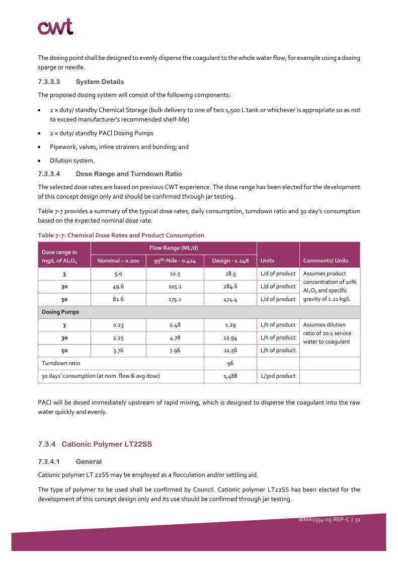
WMA1334-05-REP-C │ 51
The dosing point shall be designed to evenly disperse the coagulant to the whole water flow, for example using a dosing
sparge or needle.
7.3.3.3 System Details
The proposed dosing system will consist of the following components:
• 2 × duty/ standby Chemical Storage (bulk delivery to one of two 1,500 L tank or whichever is appropriate so as not
to exceed manufacturer’s recommended shelf-life)
• 2 × duty/ standby PACl Dosing Pumps
• Pipework, valves, inline strainers and bunding; and
• Dilution system.
7.3.3.4 Dose Range and Turndown Ratio
The selected dose rates are based on previous CWT experience. The dose range has been elected for the development
of this concept design only and should be confirmed through jar testing.
Table 7-7 provides a summary of the typical dose rates, daily consumption, turndown ratio and 30 day’s consumption
based on the expected nominal dose rate.
Table 7-7: Chemical Dose Rates and Product Consumption
Dose range in
mg/L of Al2O3
Flow Range (ML/d)
Units Comments/ Units Nominal – 0.200 95th-%ile - 0.424 Design - 1.148
3 5.0 10.5 28.5 L/d of product Assumes product
concentration of 10%
Al2O3 and specific
gravity of 1.21 kg/L
30 49.6 105.1 284.6 L/d of product
50 82.6 175.2 474.4 L/d of product
Dosing Pumps
3 0.23 0.48 1.29 L/h of product Assumes dilution
ratio of 20:1 service
water to coagulant 30 2.25 4.78 12.94 L/h of product
50 3.76 7.96 21.56 L/h of product
Turndown ratio 96
30 days’ consumption (at nom. flow & avg dose) 1,488 L/30d product
PACl will be dosed immediately upstream of rapid mixing, which is designed to disperse the coagulant into the raw
water quickly and evenly.
7.3.4 Cationic Polymer LT22SS
7.3.4.1 General
Cationic polymer LT 22SS may be employed as a flocculation and/or settling aid.
The type of polymer to be used shall be confirmed by Council. Cationic polymer LT22SS has been elected for the
development of this concept design only and its use should be confirmed through jar testing.
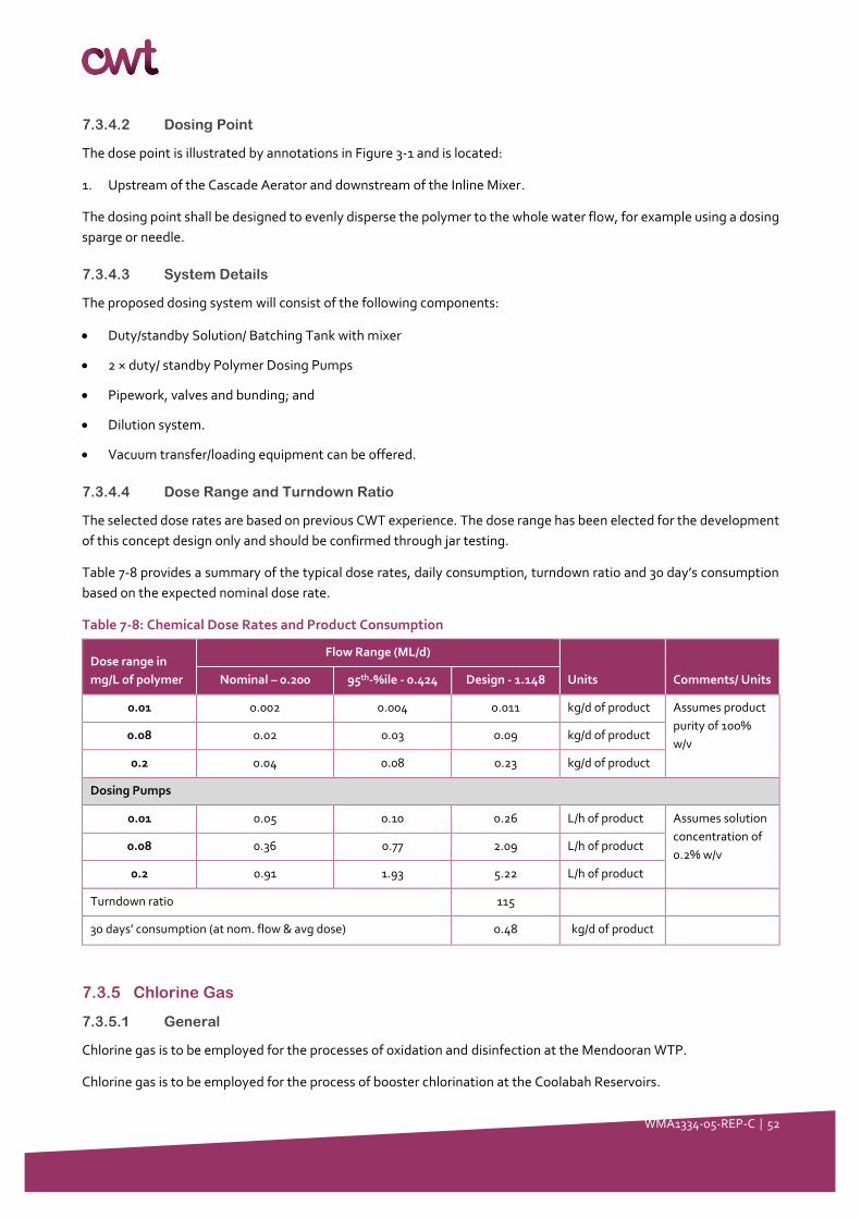
WMA1334-05-REP-C │ 52
7.3.4.2 Dosing Point
The dose point is illustrated by annotations in Figure 3-1 and is located:
1. Upstream of the Cascade Aerator and downstream of the Inline Mixer.
The dosing point shall be designed to evenly disperse the polymer to the whole water flow, for example using a dosing
sparge or needle.
7.3.4.3 System Details
The proposed dosing system will consist of the following components:
• Duty/standby Solution/ Batching Tank with mixer
• 2 × duty/ standby Polymer Dosing Pumps
• Pipework, valves and bunding; and
• Dilution system.
• Vacuum transfer/loading equipment can be offered.
7.3.4.4 Dose Range and Turndown Ratio
The selected dose rates are based on previous CWT experience. The dose range has been elected for the development
of this concept design only and should be confirmed through jar testing.
Table 7-8 provides a summary of the typical dose rates, daily consumption, turndown ratio and 30 day’s consumption
based on the expected nominal dose rate.
Table 7-8: Chemical Dose Rates and Product Consumption
Dose range in
mg/L of polymer
Flow Range (ML/d)
Units Comments/ Units Nominal – 0.200 95th-%ile - 0.424 Design - 1.148
0.01 0.002 0.004 0.011 kg/d of product Assumes product
purity of 100%
w/v 0.08 0.02 0.03 0.09 kg/d of product
0.2 0.04 0.08 0.23 kg/d of product
Dosing Pumps
0.01 0.05 0.10 0.26 L/h of product Assumes solution
concentration of
0.2% w/v 0.08 0.36 0.77 2.09 L/h of product
0.2 0.91 1.93 5.22 L/h of product
Turndown ratio 115
30 days’ consumption (at nom. flow & avg dose) 0.48 kg/d of product
7.3.5 Chlorine Gas
7.3.5.1 General
Chlorine gas is to be employed for the processes of oxidation and disinfection at the Mendooran WTP.
Chlorine gas is to be employed for the process of booster chlorination at the Coolabah Reservoirs.
WMA1334-05-REP-C │ 53
7.3.5.2 Dosing Points
The dose points are illustrated by annotations in Figure 3-1 and are located:
1. Oxidation: At the inlet to the Media Filters on the common filter feed line
2. Disinfection: After UV Disinfection Unit and prior to soda ash dosing and Clear Water Tank.
3. Booster chlorination: On the recirculation line at the Coolabah Reservoirs.
7.3.5.3 System Details
The chlorine gas systems are is to be installed in accordance with AS NZS 2927 (2001) – The Storage and Handling of
Liquefied Chlorine Gas.
Two (2) chlorine gas dosing systems are to be installed; one at the Mendooran WTP (shared between the chlorine
oxidation and disinfection points) and one at Coolabah Reservoir site.
Mendooran WTP Chlorination System
The chlorine gas dosing system at Mendooran WTP consists of the following components:
• 2 × duty/standby 70 kg chlorine gas drums on weigh scales with auto-changeover
• 1 × cold standby 70 kg chlorine gas drum
• 2 × vacuum regulators, rate valves and ejectors
• 2 × control valves
• 2 × electrical auto cylinder shutdown systems
• 2 × duty/ standby chlorine booster pumps for pre- and post-dosing
• 2 × chlorinators (duty/ duty)
• 1 × Leak detection with auto gas generator
Coolabah Reservoir Site Chlorination System
The chlorine gas dosing system at Coolabah Reservoir site consists of the following components:
• 2 × duty/standby 70 kg chlorine gas drums on weigh scales with auto-changeover
• 2 × vacuum regulators, rate valves and ejectors
• 2 × control valves
• 2 × electrical auto cylinder shutdown systems
• 2 × duty/ standby chlorine booster pumps
• 1 × chlorinator (duty)
• 1 × Leak detection with auto gas generator.
7.3.5.4 Dose Range and Turndown Ratio
Mendooran WTP Site
Table 7-9 provides a summary of the typical dose rates, daily consumption, turndown ratio and 30 day’s consumption
based on the expected nominal dose rate at the Mendooran WTP site.
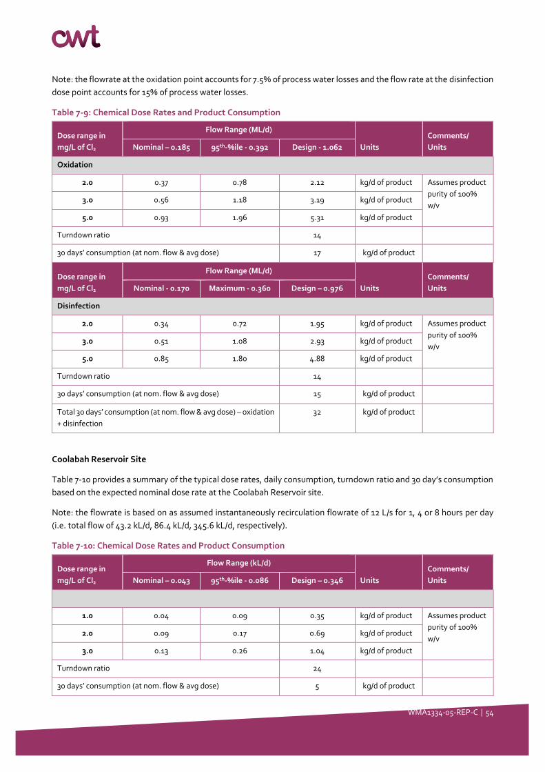
WMA1334-05-REP-C │ 54
Note: the flowrate at the oxidation point accounts for 7.5% of process water losses and the flow rate at the disinfection
dose point accounts for 15% of process water losses.
Table 7-9: Chemical Dose Rates and Product Consumption
Dose range in
mg/L of Cl2
Flow Range (ML/d)
Units
Comments/
Units Nominal – 0.185 95th-%ile - 0.392 Design - 1.062
Oxidation
2.0 0.37 0.78 2.12 kg/d of product Assumes product
purity of 100%
w/v 3.0 0.56 1.18 3.19 kg/d of product
5.0 0.93 1.96 5.31 kg/d of product
Turndown ratio 14
30 days’ consumption (at nom. flow & avg dose) 17 kg/d of product
Dose range in
mg/L of Cl2
Flow Range (ML/d)
Units
Comments/
Units Nominal - 0.170 Maximum - 0.360 Design – 0.976
Disinfection
2.0 0.34 0.72 1.95 kg/d of product Assumes product
purity of 100%
w/v 3.0 0.51 1.08 2.93 kg/d of product
5.0 0.85 1.80 4.88 kg/d of product
Turndown ratio 14
30 days’ consumption (at nom. flow & avg dose) 15 kg/d of product
Total 30 days’ consumption (at nom. flow & avg dose) – oxidation
+ disinfection
32 kg/d of product
Coolabah Reservoir Site
Table 7-10 provides a summary of the typical dose rates, daily consumption, turndown ratio and 30 day’s consumption
based on the expected nominal dose rate at the Coolabah Reservoir site.
Note: the flowrate is based on as assumed instantaneously recirculation flowrate of 12 L/s for 1, 4 or 8 hours per day
(i.e. total flow of 43.2 kL/d, 86.4 kL/d, 345.6 kL/d, respectively).
Table 7-10: Chemical Dose Rates and Product Consumption
Dose range in
mg/L of Cl2
Flow Range (kL/d)
Units
Comments/
Units Nominal – 0.043 95th-%ile - 0.086 Design – 0.346
1.0 0.04 0.09 0.35 kg/d of product Assumes product
purity of 100%
w/v 2.0 0.09 0.17 0.69 kg/d of product
3.0 0.13 0.26 1.04 kg/d of product
Turndown ratio 24
30 days’ consumption (at nom. flow & avg dose) 5 kg/d of product
WMA1334-05-REP-C │ 55
7.4 Concept Design for Inline Mixer
7.4.1 General
Good coagulation requires that all coagulant chemicals be mixed very quickly and thoroughly with the water and with
sufficient energy so that the particles and the coagulant molecules collide rapidly and often. This is particularly
important for the metal coagulants where the initial chemical reactions of adsorption-destabilisation occur in less than
1 second.
The Inline Mixer will be used to mix coagulant downstream of the Blending Tank, with the outlet of the Inlet Mixer
connected with the existing Cascade Aerator.
7.4.2 Design Requirements
The design requirements for Inline Mixer are as follows:
The Inline Mixer will be of static or mechanical type.
Monitoring instrumentation will be provided in the pipework between the Blending Tank and Inline Mixer. These
details are outlined in Section 8.
The works shall be designed to accommodate the inline dosing of coagulant and soda ash. The details of the
chemical dosing systems are listed in Section 7.
The dosing point for coagulant shall be located downstream of the soda ash dosing point and monitoring
equipment, and upstream of the mixer.
The dosing point for soda ash shall be located downstream of the Blending Tank and upstream of the monitoring
equipment, coagulant dosing and Inline Mixer.
Materials of construction must be compliant with the chemicals dosed.
The outlet of the Inline Mixer shall be connected to the inlet of the Cascade Aerator.
The rapid mixing stage should provide at least 2 seconds’ detention time for in-line mixing. The mixing gradient (i.e. G
value) for the rapid mixing stage should be at least 750 s-1.
Table 7-11: Coagulation System Options Design
Item Details Value Comments
In-line mixer Mixing gradient (s-1) 750 Mechanical mixing
Coefficient of Variance 0.05 Static mixer
After inline mixing, the coagulated water will flow on to the existing Cascade Aerator where coagulated water will
gravitate towards the Flocculation Tank.
7.5 Concept Design for Service Water Pumps
7.5.1 General
Two (2) new duty/ standby Service Water Pumps connected to a pressure accumulator shall be made available at the
outlet of the Clear Water Tank to provide service water for:
WMA1334-05-REP-C │ 56
• Chemical batching, dilution, carrier and flushing requirements
• Service water to an onsite hose reel for chemical area washdown inside chemical dosing room
• Other
7.5.2 Design Requirements
The design requirements for the service water pumps is as follows:
• The service water pumps shall be sized to:
Provide sufficient dilution water for chemical makeup/ batching and delivery as follows:
▪ Soda ash shall be:
– Batched as a 10% w/v solution
– Delivered at a 10:1 ratio of carrier water to soda ash solution
▪ Potassium permanganate shall be:
– Batched as a 2% w/v solution (without heating). Note: this is an estimate based on previous experience.
Solubility can vary depending on mixing efficacy and temperature.
– Delivered at a 10:1 ratio of carrier water to potassium permanganate slurry
▪ Polymer LT22S shall be:
– Batched as a 0.2% w/v solution (typically 0.15-0.3%)
– Delivered at a 10:1 ratio of carrier water to polymer solution
▪ Coagulant PACl shall be delivered as at a 20:1 ratio of carrier water to coagulant
▪ Chlorine solution shall be delivered at 10 L/min (Chlorine Handbook)
Provide service water to one (1) standard hose rated to deliver 65 L/min
Include contingency of +25%
The system will comprise two (2) duty/ standby Service Water Pumps connected to a pressure accumulator to maintain
a constant pressure throughout the service water reticulation and deliver up to approximately 130 L/min.
7.5.3 Concept Design Calculations
The following calculations were used to determine the Service Water Pump sizing requirements and turndown ratio
for the three design capacities i.e. 0.200, 0.424 and 1.148 ML/d (which correspond to nominal, 95th%ile and design flow
rates).
Contractor
Table 7-12 Service Water Pumps Design Calculations
Service water requirements Nominal
WTP flow
95th%ile
WTP flow
Design
Flow Comments
Number of pumps 2
Configuration Duty/standby
1 × standard hose for chemical washdown
area (L/min)
65.00 65.00 65.00 Assumes standard hose delivers 65
L/min
WMA1334-05-REP-C │ 57
Service water requirements Nominal
WTP flow
95th%ile
WTP flow
Design
Flow Comments
Soda ash batching and carrier water
(L/min)
1.53 3.24 8.77 Based on 10% w/v solution, 10:1 dilution
KMnO4 batching and carrier water (L/min) 0.39 0.82 2.22 Based on 2% w/v solution, 10:1 dilution
Coagulant carrier water (L/min) 1.25 2.65 7.19 Based on 20:1 dilution
Polymer batching and carrier water (L/min) 0.15 0.32 0.87 Based on 0.2% solution, 10:1 dilution
Chlorine carrier water (L/min) 20 20 20 Based on Chlorine Handbook data
Contingency +/- 25% 22.08 23.01 26.01
Turndown ratio To be determined by contractor
Total estimation (L/min) 110.4 115.0 130.1
Total estimation (L/s) 1.8 1.9 2.2
7.6 Concept Design for Wastewater Holding Tank
7.6.1 General
• A Wastewater Holding Tank of approximately 6 kL is to be installed at site for transfer of chemical waste in the
event of a chemical spill.
• The Wastewater Holding Tank will not be plumbed in by rather be fed by temporary 25 mm flexible hose connected
to an uninstalled chemical transfer pump.
7.6.2 Design Requirements
The design requirements are as follows:
• Wastewater Holding Tank sized to contain 110% of liquid chemical stored at site or 6 kL; whichever is larger
• Tank materials of construction to be suitable for contact with corrosive liquids
• Uninstalled chemical transfer pump to transfer contained spills to tank via an inlet value situated below eye level).
• Camlock fitting at tank for transfer of waste offsite
• Pressure relief valve
• Access hatch for inspection and maintenance
• Scour valve for maintenance cleans
• Level sensor affixed to top of tank to alert operators when tank is approaching its maximum limit.
7.7 Safety in Design Considerations
The following safety equipment will be available:
• Chemical bunds around liquid chemical dosing systems sized to contain 110% of chemical storage volumes with
entry and exit ladders as required.
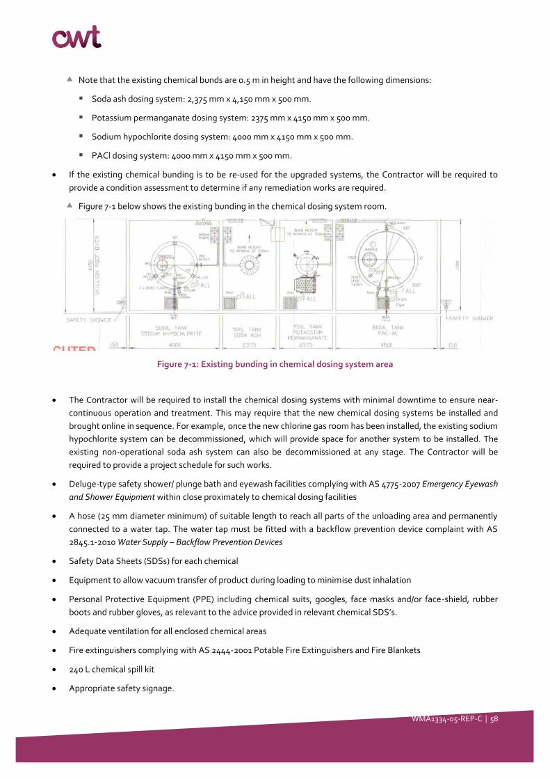
WMA1334-05-REP-C │ 58
Note that the existing chemical bunds are 0.5 m in height and have the following dimensions:
▪ Soda ash dosing system: 2,375 mm x 4,150 mm x 500 mm.
▪ Potassium permanganate dosing system: 2375 mm x 4150 mm x 500 mm.
▪ Sodium hypochlorite dosing system: 4000 mm x 4150 mm x 500 mm.
▪ PACl dosing system: 4000 mm x 4150 mm x 500 mm.
• If the existing chemical bunding is to be re-used for the upgraded systems, the Contractor will be required to
provide a condition assessment to determine if any remediation works are required.
Figure 7-1 below shows the existing bunding in the chemical dosing system room.
Figure 7-1: Existing bunding in chemical dosing system area
• The Contractor will be required to install the chemical dosing systems with minimal downtime to ensure near-
continuous operation and treatment. This may require that the new chemical dosing systems be installed and
brought online in sequence. For example, once the new chlorine gas room has been installed, the existing sodium
hypochlorite system can be decommissioned, which will provide space for another system to be installed. The
existing non-operational soda ash system can also be decommissioned at any stage. The Contractor will be
required to provide a project schedule for such works.
• Deluge-type safety shower/ plunge bath and eyewash facilities complying with AS 4775-2007 Emergency Eyewash
and Shower Equipment within close proximately to chemical dosing facilities
• A hose (25 mm diameter minimum) of suitable length to reach all parts of the unloading area and permanently
connected to a water tap. The water tap must be fitted with a backflow prevention device complaint with AS
2845.1-2010 Water Supply – Backflow Prevention Devices
• Safety Data Sheets (SDSs) for each chemical
• Equipment to allow vacuum transfer of product during loading to minimise dust inhalation
• Personal Protective Equipment (PPE) including chemical suits, googles, face masks and/or face-shield, rubber
boots and rubber gloves, as relevant to the advice provided in relevant chemical SDS’s.
• Adequate ventilation for all enclosed chemical areas
• Fire extinguishers complying with AS 2444-2001 Potable Fire Extinguishers and Fire Blankets
• 240 L chemical spill kit
• Appropriate safety signage.

WMA1334-05-REP-C │ 59
• The following standards are applicable to the Mendooran WTP chemical dosing system upgrades and shall be
referenced in the technical specification:
AS NZS 2927:2001 The storage and handling of liquefied chlorine gas
AS 3780: 2008 The storage and handling of corrosive substances
AS 4326: 2008 The storage and handling of oxidizing agents
AS 2845: 2010 Water supply—Backflow preventions devices
AS 4775: 2007 Emergency eyewash and shower equipment
AS NZS 3000: 2007 Wiring rules.
WMA1334-05-REP-C │ 60
8 Work Package 3: Online Instrumentation & Process
Control
8.1 Description of works
8.1.1 Overview
The following table is an excerpt of Table 3-1 is summarises the activities to be addressed in this Section of the Report.
Table 8-1: Scope of Works and Activities
No. Work packages Activities
WP3 Online instrumentation and
process control
• Identification for all required instrumentation including:
o Analytical: turbidimeters, pH, free chlorine, UVI
o Flow switches, flow meters and level sensors
o Variable speed drives at:
▪ Castlereagh Riverbed Pumps
▪ Backup Bore Pumps
▪ Low level/filter feed pumps
• Describe process control philosophy (alarm setpoints and feedback control)
for:
o All chemical dosing systems listed in WP2
o Filtration forward and backwash control
o Analytical instrumentation in accordance with CWT and Hunter H2O
recommendations (defined in Section 8)
8.1.2 General
The Mendooran WTP shall be upgraded with sufficient automation for remote unmanned operation with periodic on-
site input from operators of around 20 man-hours per week at site (excluding travel to/from site).
The control system upgrades to the WTP shall include the following control system components:
If possible, the control system shall be linked to the raw water supply control systems via a RTU system
A master Programmable Logic Controller (PLC) system and programming in accordance with Hunter H2O’s
recommendations
Proprietary PLC systems where relevant such as those made available with the UV disinfection systems
Supervisory Control and Data Acquisition (SCADA) system and programming; including:
SCADA information and processes status and alarms
SCADA to include time stamped events and alarm logs
SCADA HMI computer
All necessary SCADA I/O for remote monitoring and control from WSC’s SCADA system
The option to link new RTU units with WSC’s existing ELPRO Automation system
Local controls for components as applicable
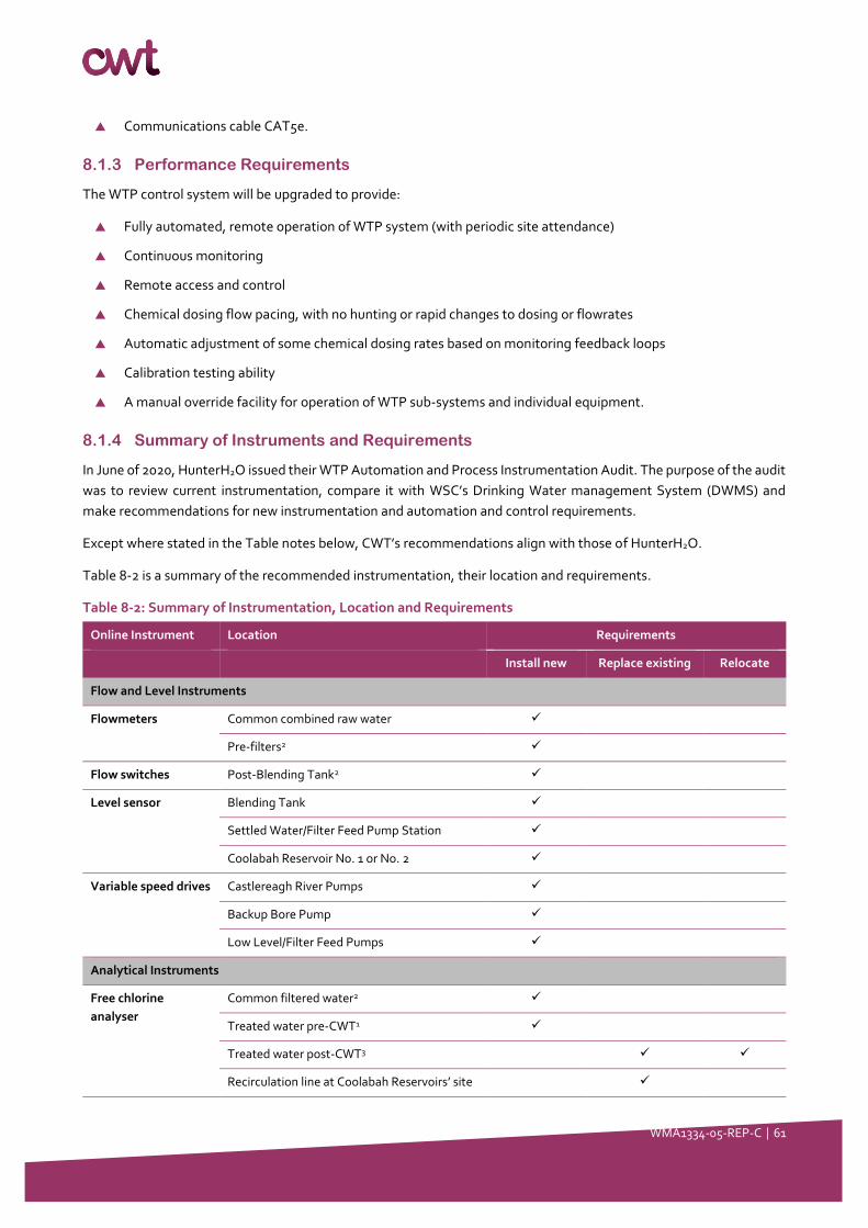
WMA1334-05-REP-C │ 61
Communications cable CAT5e.
8.1.3 Performance Requirements
The WTP control system will be upgraded to provide:
Fully automated, remote operation of WTP system (with periodic site attendance)
Continuous monitoring
Remote access and control
Chemical dosing flow pacing, with no hunting or rapid changes to dosing or flowrates
Automatic adjustment of some chemical dosing rates based on monitoring feedback loops
Calibration testing ability
A manual override facility for operation of WTP sub-systems and individual equipment.
8.1.4 Summary of Instruments and Requirements
In June of 2020, HunterH2O issued their WTP Automation and Process Instrumentation Audit. The purpose of the audit
was to review current instrumentation, compare it with WSC’s Drinking Water management System (DWMS) and
make recommendations for new instrumentation and automation and control requirements.
Except where stated in the Table notes below, CWT’s recommendations align with those of HunterH2O.
Table 8-2 is a summary of the recommended instrumentation, their location and requirements.
Table 8-2: Summary of Instrumentation, Location and Requirements
Online Instrument Location Requirements
Install new Replace existing Relocate
Flow and Level Instruments
Flowmeters Common combined raw water ✓
Pre-filters2 ✓
Flow switches Post-Blending Tank2 ✓
Level sensor Blending Tank ✓
Settled Water/Filter Feed Pump Station ✓
Coolabah Reservoir No. 1 or No. 2 ✓
Variable speed drives Castlereagh River Pumps ✓
Backup Bore Pump ✓
Low Level/Filter Feed Pumps ✓
Analytical Instruments
Free chlorine
analyser
Common filtered water2 ✓
Treated water pre-CWT1 ✓
Treated water post-CWT3 ✓ ✓
Recirculation line at Coolabah Reservoirs’ site ✓
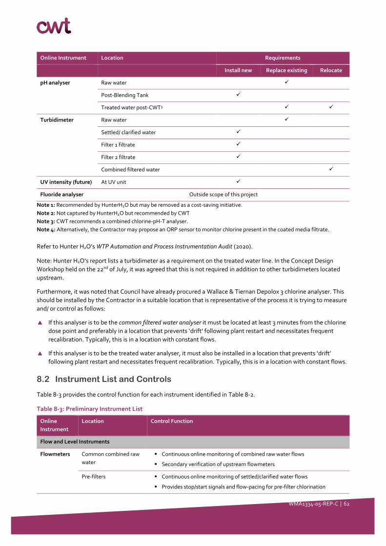
WMA1334-05-REP-C │ 62
Online Instrument Location Requirements
Install new Replace existing Relocate
pH analyser Raw water ✓
Post-Blending Tank ✓
Treated water post-CWT3 ✓ ✓
Turbidimeter Raw water ✓
Settled/ clarified water ✓
Filter 1 filtrate ✓
Filter 2 filtrate ✓
Combined filtered water ✓
UV intensity (future) At UV unit ✓
Fluoride analyser Outside scope of this project
Note 1: Recommended by HunterH2O but may be removed as a cost-saving initiative.
Note 2: Not captured by HunterH2O but recommended by CWT
Note 3: CWT recommends a combined chlorine-pH-T analyser.
Note 4: Alternatively, the Contractor may propose an ORP sensor to monitor chlorine present in the coated media filtrate.
Refer to Hunter H2O’s WTP Automation and Process Instrumentation Audit (2020).
Note: Hunter H2O’s report lists a turbidimeter as a requirement on the treated water line. In the Concept Design
Workshop held on the 22nd of July, it was agreed that this is not required in addition to other turbidimeters located
upstream.
Furthermore, it was noted that Council have already procured a Wallace & Tiernan Depolox 3 chlorine analyser. This
should be installed by the Contractor in a suitable location that is representative of the process it is trying to measure
and/ or control as follows:
If this analyser is to be the common filtered water analyser it must be located at least 3 minutes from the chlorine
dose point and preferably in a location that prevents ‘drift’ following plant restart and necessitates frequent
recalibration. Typically, this is in a location with constant flows.
If this analyser is to be the treated water analyser, it must also be installed in a location that prevents ‘drift’
following plant restart and necessitates frequent recalibration. Typically, this is in a location with constant flows.
8.2 Instrument List and Controls
Table 8-3 provides the control function for each instrument identified in Table 8-2.
Table 8-3: Preliminary Instrument List
Online
Instrument
Location Control Function
Flow and Level Instruments
Flowmeters Common combined raw
water
▪ Continuous online monitoring of combined raw water flows
▪ Secondary verification of upstream flowmeters
Pre-filters ▪ Continuous online monitoring of settled/clarified water flows
▪ Provides stop/start signals and flow-pacing for pre-filter chlorination
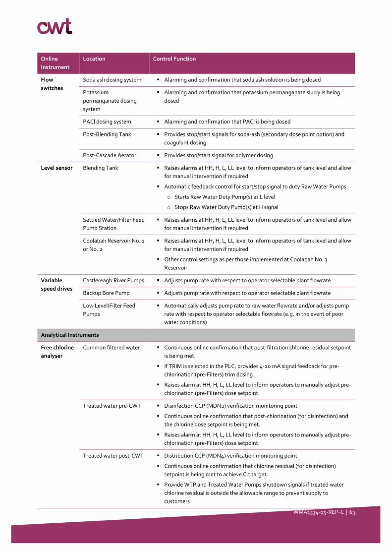
WMA1334-05-REP-C │ 63
Online
Instrument
Location Control Function
Flow
switches
Soda ash dosing system ▪ Alarming and confirmation that soda ash solution is being dosed
Potassium
permanganate dosing
system
▪ Alarming and confirmation that potassium permanganate slurry is being
dosed
PACl dosing system ▪ Alarming and confirmation that PACl is being dosed
Post-Blending Tank ▪ Provides stop/start signals for soda-ash (secondary dose point option) and
coagulant dosing
Post-Cascade Aerator ▪ Provides stop/start signal for polymer dosing
Level sensor Blending Tank ▪ Raises alarms at HH, H, L, LL level to inform operators of tank level and allow
for manual intervention if required
▪ Automatic feedback control for start/stop signal to duty Raw Water Pumps
o Starts Raw Water Duty Pump(s) at L level
o Stops Raw Water Duty Pump(s) at H signal
Settled Water/Filter Feed
Pump Station
▪ Raises alarms at HH, H, L, LL level to inform operators of tank level and allow
for manual intervention if required
Coolabah Reservoir No. 1
or No. 2
▪ Raises alarms at HH, H, L, LL level to inform operators of tank level and allow
for manual intervention if required
▪ Other control settings as per those implemented at Coolabah No. 3
Reservoir.
Variable
speed drives
Castlereagh River Pumps ▪ Adjusts pump rate with respect to operator selectable plant flowrate
Backup Bore Pump ▪ Adjusts pump rate with respect to operator selectable plant flowrate
Low Level/Filter Feed
Pumps
▪ Automatically adjusts pump rate to raw water flowrate and/or adjusts pump
rate with respect to operator selectable flowrate (e.g. in the event of poor
water conditions)
Analytical Instruments
Free chlorine
analyser
Common filtered water ▪ Continuous online confirmation that post-filtration chlorine residual setpoint
is being met.
▪ If TRIM is selected in the PLC, provides 4-20 mA signal feedback for pre-
chlorination (pre-Filters) trim dosing
▪ Raises alarm at HH, H, L, LL level to inform operators to manually adjust pre-
chlorination (pre-Filters) dose setpoint.
Treated water pre-CWT ▪ Disinfection CCP (MDN2) verification monitoring point
▪ Continuous online confirmation that post-chlorination (for disinfection) and
the chlorine dose setpoint is being met.
▪ Raises alarm at HH, H, L, LL level to inform operators to manually adjust pre-
chlorination (pre-Filters) dose setpoint.
Treated water post-CWT ▪ Distribution CCP (MDN4) verification monitoring point
▪ Continuous online confirmation that chlorine residual (for disinfection)
setpoint is being met to achieve C.t target.
▪ Provide WTP and Treated Water Pumps shutdown signals if treated water
chlorine residual is outside the allowable range to prevent supply to
customers
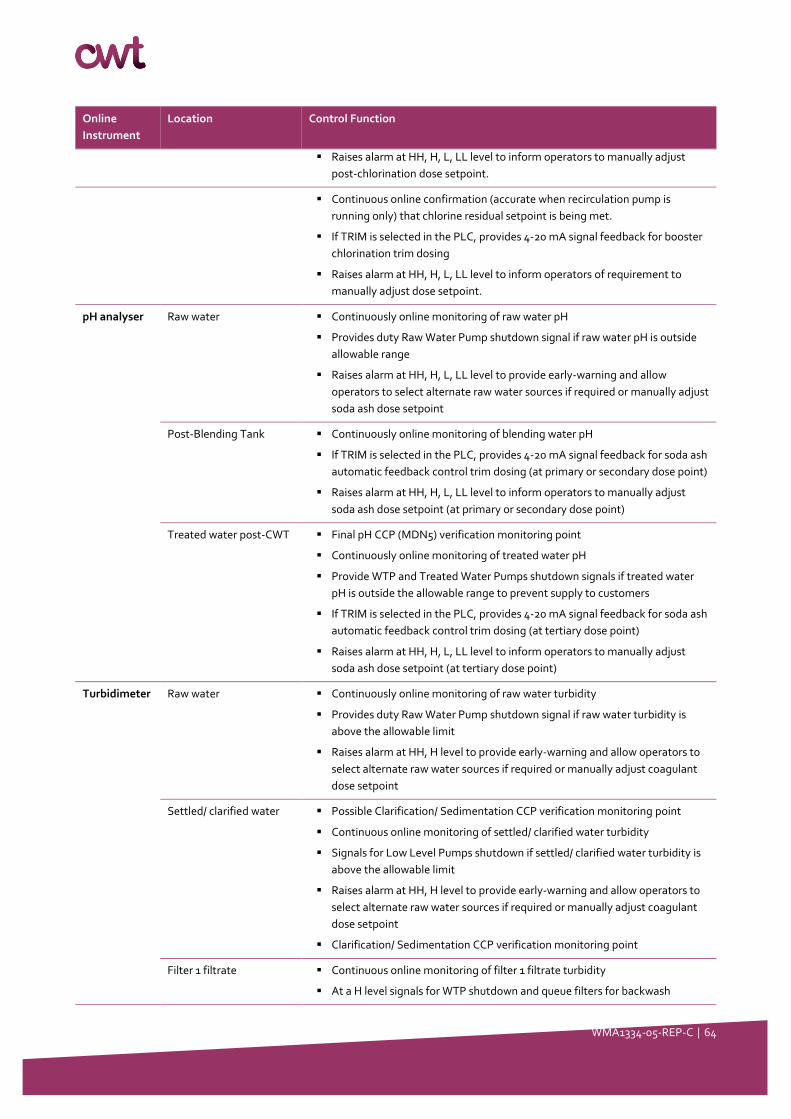
WMA1334-05-REP-C │ 64
Online
Instrument
Location Control Function
▪ Raises alarm at HH, H, L, LL level to inform operators to manually adjust
post-chlorination dose setpoint.
▪ Continuous online confirmation (accurate when recirculation pump is
running only) that chlorine residual setpoint is being met.
▪ If TRIM is selected in the PLC, provides 4-20 mA signal feedback for booster
chlorination trim dosing
▪ Raises alarm at HH, H, L, LL level to inform operators of requirement to
manually adjust dose setpoint.
pH analyser Raw water ▪ Continuously online monitoring of raw water pH
▪ Provides duty Raw Water Pump shutdown signal if raw water pH is outside
allowable range
▪ Raises alarm at HH, H, L, LL level to provide early-warning and allow
operators to select alternate raw water sources if required or manually adjust
soda ash dose setpoint
Post-Blending Tank ▪ Continuously online monitoring of blending water pH
▪ If TRIM is selected in the PLC, provides 4-20 mA signal feedback for soda ash
automatic feedback control trim dosing (at primary or secondary dose point)
▪ Raises alarm at HH, H, L, LL level to inform operators to manually adjust
soda ash dose setpoint (at primary or secondary dose point)
Treated water post-CWT ▪ Final pH CCP (MDN5) verification monitoring point
▪ Continuously online monitoring of treated water pH
▪ Provide WTP and Treated Water Pumps shutdown signals if treated water
pH is outside the allowable range to prevent supply to customers
▪ If TRIM is selected in the PLC, provides 4-20 mA signal feedback for soda ash
automatic feedback control trim dosing (at tertiary dose point)
▪ Raises alarm at HH, H, L, LL level to inform operators to manually adjust
soda ash dose setpoint (at tertiary dose point)
Turbidimeter Raw water ▪ Continuously online monitoring of raw water turbidity
▪ Provides duty Raw Water Pump shutdown signal if raw water turbidity is
above the allowable limit
▪ Raises alarm at HH, H level to provide early-warning and allow operators to
select alternate raw water sources if required or manually adjust coagulant
dose setpoint
Settled/ clarified water ▪ Possible Clarification/ Sedimentation CCP verification monitoring point
▪ Continuous online monitoring of settled/ clarified water turbidity
▪ Signals for Low Level Pumps shutdown if settled/ clarified water turbidity is
above the allowable limit
▪ Raises alarm at HH, H level to provide early-warning and allow operators to
select alternate raw water sources if required or manually adjust coagulant
dose setpoint
▪ Clarification/ Sedimentation CCP verification monitoring point
Filter 1 filtrate ▪ Continuous online monitoring of filter 1 filtrate turbidity
▪ At a H level signals for WTP shutdown and queue filters for backwash
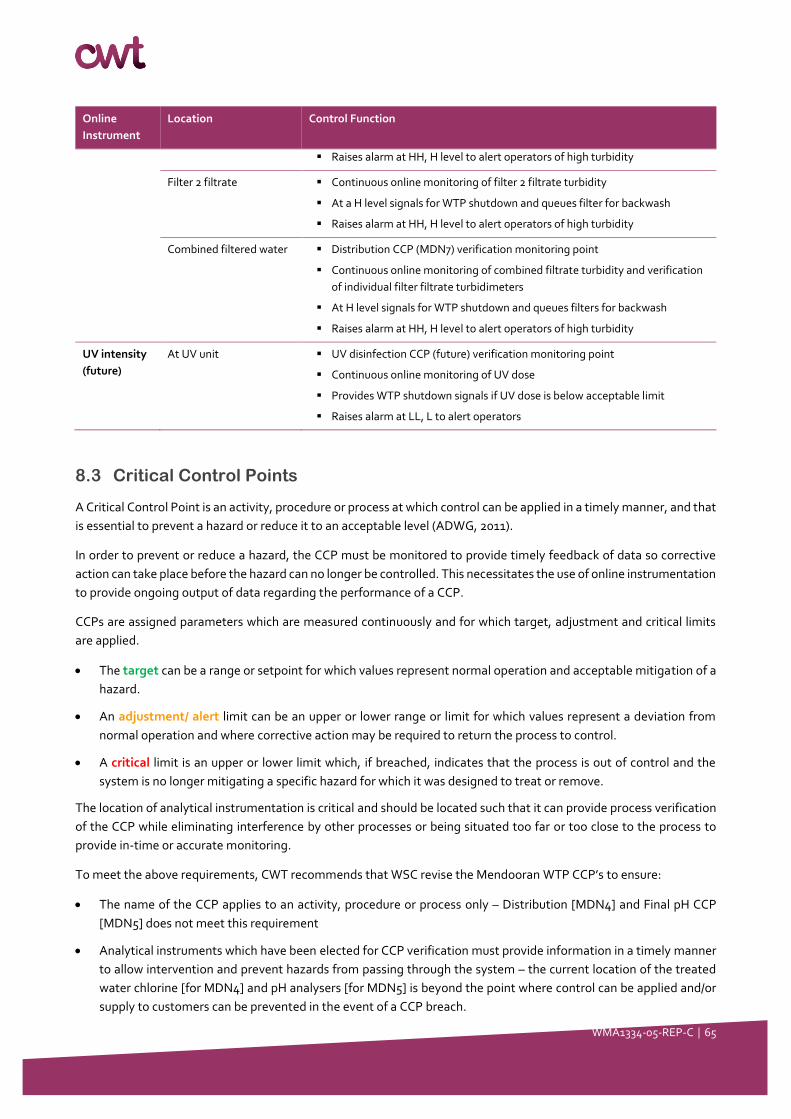
WMA1334-05-REP-C │ 65
Online
Instrument
Location Control Function
▪ Raises alarm at HH, H level to alert operators of high turbidity
Filter 2 filtrate ▪ Continuous online monitoring of filter 2 filtrate turbidity
▪ At a H level signals for WTP shutdown and queues filter for backwash
▪ Raises alarm at HH, H level to alert operators of high turbidity
Combined filtered water ▪ Distribution CCP (MDN7) verification monitoring point
▪ Continuous online monitoring of combined filtrate turbidity and verification
of individual filter filtrate turbidimeters
▪ At H level signals for WTP shutdown and queues filters for backwash
▪ Raises alarm at HH, H level to alert operators of high turbidity
UV intensity
(future)
At UV unit ▪ UV disinfection CCP (future) verification monitoring point
▪ Continuous online monitoring of UV dose
▪ Provides WTP shutdown signals if UV dose is below acceptable limit
▪ Raises alarm at LL, L to alert operators
8.3 Critical Control Points
A Critical Control Point is an activity, procedure or process at which control can be applied in a timely manner, and that
is essential to prevent a hazard or reduce it to an acceptable level (ADWG, 2011).
In order to prevent or reduce a hazard, the CCP must be monitored to provide timely feedback of data so corrective
action can take place before the hazard can no longer be controlled. This necessitates the use of online instrumentation
to provide ongoing output of data regarding the performance of a CCP.
CCPs are assigned parameters which are measured continuously and for which target, adjustment and critical limits
are applied.
• The target can be a range or setpoint for which values represent normal operation and acceptable mitigation of a
hazard.
• An adjustment/ alert limit can be an upper or lower range or limit for which values represent a deviation from
normal operation and where corrective action may be required to return the process to control.
• A critical limit is an upper or lower limit which, if breached, indicates that the process is out of control and the
system is no longer mitigating a specific hazard for which it was designed to treat or remove.
The location of analytical instrumentation is critical and should be located such that it can provide process verification
of the CCP while eliminating interference by other processes or being situated too far or too close to the process to
provide in-time or accurate monitoring.
To meet the above requirements, CWT recommends that WSC revise the Mendooran WTP CCP’s to ensure:
• The name of the CCP applies to an activity, procedure or process only – Distribution [MDN4] and Final pH CCP
[MDN5] does not meet this requirement
• Analytical instruments which have been elected for CCP verification must provide information in a timely manner
to allow intervention and prevent hazards from passing through the system – the current location of the treated
water chlorine [for MDN4] and pH analysers [for MDN5] is beyond the point where control can be applied and/or
supply to customers can be prevented in the event of a CCP breach.
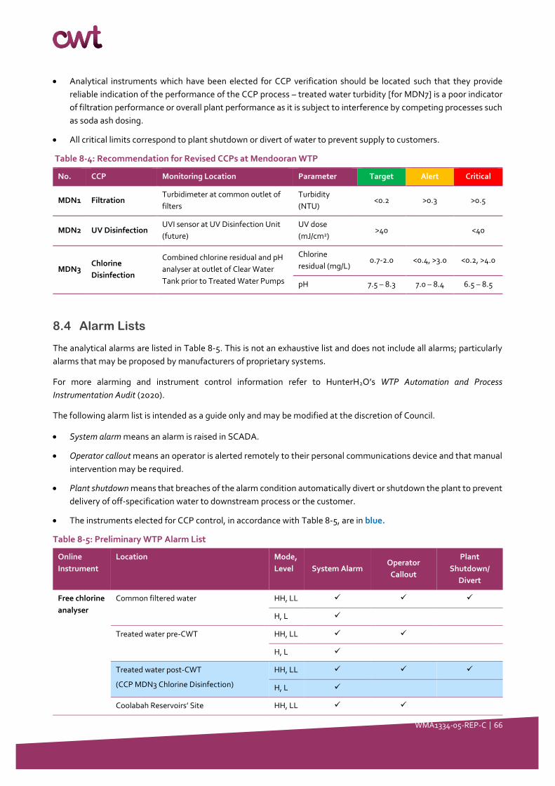
WMA1334-05-REP-C │ 66
• Analytical instruments which have been elected for CCP verification should be located such that they provide
reliable indication of the performance of the CCP process – treated water turbidity [for MDN7] is a poor indicator
of filtration performance or overall plant performance as it is subject to interference by competing processes such
as soda ash dosing.
• All critical limits correspond to plant shutdown or divert of water to prevent supply to customers.
Table 8-4: Recommendation for Revised CCPs at Mendooran WTP
No. CCP Monitoring Location Parameter Target Alert Critical
MDN1 Filtration Turbidimeter at common outlet of
filters
Turbidity
(NTU) <0.2 >0.3 >0.5
MDN2 UV Disinfection UVI sensor at UV Disinfection Unit
(future)
UV dose
(mJ/cm2) >40 <40
MDN3 Chlorine
Disinfection
Combined chlorine residual and pH
analyser at outlet of Clear Water
Tank prior to Treated Water Pumps
Chlorine
residual (mg/L) 0.7-2.0 <0.4, >3.0 <0.2, >4.0
pH 7.5 – 8.3 7.0 – 8.4 6.5 – 8.5
8.4 Alarm Lists
The analytical alarms are listed in Table 8-5. This is not an exhaustive list and does not include all alarms; particularly
alarms that may be proposed by manufacturers of proprietary systems.
For more alarming and instrument control information refer to HunterH2O’s WTP Automation and Process
Instrumentation Audit (2020).
The following alarm list is intended as a guide only and may be modified at the discretion of Council.
• System alarm means an alarm is raised in SCADA.
• Operator callout means an operator is alerted remotely to their personal communications device and that manual
intervention may be required.
• Plant shutdown means that breaches of the alarm condition automatically divert or shutdown the plant to prevent
delivery of off-specification water to downstream process or the customer.
• The instruments elected for CCP control, in accordance with Table 8-5, are in blue.
Table 8-5: Preliminary WTP Alarm List
Online
Instrument
Location Mode,
Level System Alarm Operator
Callout
Plant
Shutdown/
Divert
Free chlorine
analyser
Common filtered water HH, LL ✓ ✓ ✓
H, L ✓
Treated water pre-CWT HH, LL ✓ ✓
H, L ✓
Treated water post-CWT
(CCP MDN3 Chlorine Disinfection)
HH, LL ✓ ✓ ✓
H, L ✓
Coolabah Reservoirs’ Site HH, LL ✓ ✓
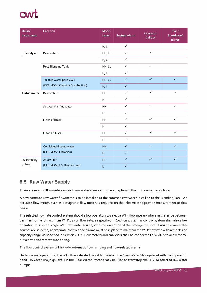
WMA1334-05-REP-C │ 67
Online
Instrument
Location Mode,
Level System Alarm Operator
Callout
Plant
Shutdown/
Divert
H, L ✓
pH analyser Raw water HH, LL ✓ ✓
H, L ✓
Post-Blending Tank HH, LL ✓ ✓
H, L ✓
Treated water post-CWT
(CCP MDN3 Chlorine Disinfection)
HH, LL ✓ ✓ ✓
H, L ✓
Turbidimeter Raw water HH ✓ ✓ ✓
H ✓
Settled/ clarified water HH ✓ ✓ ✓
H ✓
Filter 1 filtrate HH ✓ ✓ ✓
H ✓
Filter 2 filtrate HH ✓ ✓ ✓
H ✓
Combined filtered water
(CCP MDN1 Filtration)
HH ✓ ✓ ✓
H ✓
UV intensity
(future)
At UV unit
(CCP MDN2 UV Disinfection)
LL ✓ ✓ ✓
L ✓
8.5 Raw Water Supply
There are existing flowmeters on each raw water source with the exception of the onsite emergency bore.
A new common raw water flowmeter is to be installed at the common raw water inlet line to the Blending Tank. An
accurate flow meter, such as a magnetic flow meter, is required on the inlet main to provide measurement of flow
rates.
The selected flow rate control system should allow operators to select a WTP flow rate anywhere in the range between
the minimum and maximum WTP design flow rate, as specified in Section 4.2.2. The control system shall also allow
operators to select a single WTP raw water source, with the exception of the Emergency Bore. If multiple raw water
sources are selected, appropriate controls and alarms must be in place to maintain the WTP flow rate within the design
capacity range, as specified in Section 4.2.2. Flow meters and analysers shall be connected to SCADA to allow for call
out alarms and remote monitoring.
The flow control system will include automatic flow ramping and flow-related alarms.
Under normal operations, the WTP flow rate shall be set to maintain the Clear Water Storage level within an operating
band. However, low/high levels in the Clear Water Storage may be used to start/stop the SCADA selected raw water
pump(s).
WMA1334-05-REP-C │ 68
8.6 Chemical Dosing Systems
Chemical doses should be able to be selected on the SCADA screen in terms of the “mg/L” dose of active ingredient in
a given chemical. The control system will calculate the required dosing pump rate based on the dose setpoint and the
WTP flow rate.
All chemical dosing will be flow proportional and adjusted with respect to the first flowmeter upstream of the dose
point.
Where there is no flowmeter immediately upstream of the chemical dose point, a flow switch shall be made available
to allow the stop/start of the chemical dosing.
Trim dosing shall be made available for the soda ash and chlorine gas dosing systems and will be described further in
their relevant Sections.
Where chemical systems dose to several different points and share a common standby dosing pump, the SCADA
system will need to allow for checks and alarms so that the standby pump uses the correct flow pacing and/or feedback
analyser signals when it is used.
8.6.1 Soda Ash
When soda ash dosing is selected to operate, the required soda ash dose rate set point is entered into SCADA as “mg/L
of Na2CO3.”
The required soda ash dose rate set point shall be entered into SCADA. The dose required shall be determined by the
operators and should be adjusted with respect to the incoming raw water pH (as measured online) and alkalinity (as
measured in the lab).
The soda ash dosing system will operate when the following conditions are satisfied:
• The Raw Water Pumps are operating i.e. the front-end of the WTP is in operation
• The WTP flow rate as selected by the operator in the PLC is equal to or ±10% as detected at the common raw water
flowmeter
• The soda ash dosing system is selected to operate
• The soda ash dosing system is available and online
If the soda ash dosing system is selected to operate but is not available due to any system fault, an alarm will be raised,
and the system will not run.
Soda ash dosing can occur at only one of three locations in the plant (as described in Section 7.3.1) and therefore share
2 × duty/ standby dosing pumps. An “Automatic / Manual / off” selection shall be provided on SCADA for the dosing
pumps. Automatic transfer to the standby pump is required on detection of a duty pump failure or soda ash solution
flow fault.
8.6.2 Potassium Permanganate
The required potassium permanganate dose rate set point shall be entered into SCADA as “mg/L of KMnO4.” The dose
required shall be determined by the operators and should be proportional to the soluble manganese concentration of
the raw water.
The potassium permanganate dosing system will operate when the following conditions are satisfied:
• The Raw Water Pumps are operating i.e. the front-end of the WTP is in operation
WMA1334-05-REP-C │ 69
• The WTP flow rate as selected by the operator in the PLC is equal to or ±10% as detected at the common raw water
flowmeter
• The potassium permanganate dosing system is selected to operate
• The potassium permanganate dosing system is available and online
If the potassium permanganate dosing system is selected to operate but is not available due to any system fault, an
alarm will be raised, and the system will not run.
Potassium permanganate dosing occurs at one location in the plant (as described in Section 7.3.2) and therefore has
dedicated 2 × duty/ standby dosing pumps. An “Automatic / Manual / off” selection shall be provided on SCADA for the
dosing pumps. Automatic transfer to the standby pump is required on detection of a duty pump failure or potassium
permanganate slurry flow fault.
8.6.3 Polyaluminium Chloride (PACl)
The required PACl dose rate set point shall be entered into SCADA as “mg/L of Al2O3.” The dose required shall be
determined by the operators and should be adjusted with respect to the incoming raw water turbidity (as measured
online) and daily jar tests (as performed in the lab).
The PACl dosing system will operate when the following conditions are satisfied:
• The Raw Water Pumps are operating i.e. the front-end of the WTP is in operation
• The WTP flow rate as selected by the operator in the PLC is equal to or ±10% as detected at a flow switch
• The PACl dosing system is selected to operate
• The PACl dosing system is available and online.
If the PACl dosing system is selected to operate but is not available due to any system fault, an alarm will be raised,
and the system will not run.
PACl dosing occurs at one location in the plant (as described in Section 7.3.3) and therefore has dedicated 2 × duty/
standby dosing pumps. An “Automatic / Manual / off” selection will be provided on SCADA for the dosing pumps.
Automatic transfer to the standby pump will be required on detection of a duty pump failure or PACl flow fault.
8.6.4 Polymer
When polymer dosing is selected to operate, the required polymer dose rate set point is entered into SCADA as “mg/L
of polymer.” The dose required shall be determined by the operators and should be adjusted with respect to the
incoming raw water turbidity (as measured online) and daily jar tests (as performed in the lab).
The polymer dosing system will operate when the following conditions are satisfied:
• The Raw Water Pumps are operating i.e. the front-end of the WTP is in operation
• The WTP flow rate as selected by the operator in the PLC is equal to or ±10% as detected at a flow switch
• The polymer dosing system is selected to operate
• The polymer dosing system is available and online.
Polymer dosing can occur at one location in the plant (as described in Section 7.3.4) and therefore has dedicated 2 ×
duty/ standby dosing pumps. An “Automatic / Manual / off” selection will be provided on SCADA for the dosing pumps.
Automatic transfer to the standby pump will be required on detection of a duty pump failure or polymer flow fault. An
“Automatic / Manual / off” selection will be provided on SCADA for the dosing pumps. Automatic transfer to the
standby pump will be required on detection of a duty pump failure or polymer flow fault.
WMA1334-05-REP-C │ 70
8.6.5 Chlorine Dosing
8.6.5.1 Chlorine Dosing for Oxidation (Pre-Dosing)
The required chlorine dose rate set point shall be entered into SCADA as “mg/L of Cl2.” The dose required for oxidation
shall be determined by the operators and should be adjusted to achieve a minimum detectable chlorine residual at the
outlet of the filters. The acceptable chlorine dose range does not need to exceed 0.5 mg/L; only a minimal detectable
limit (e.g. 0.02 mg/L) is required to ensure that the filter media beds are saturated with chlorine to maintain a
manganese-oxide coating for manganese removal.
The chlorine (for oxidation) dosing system will operate when the following conditions are satisfied:
• The Low Lift Pumps are operating i.e. the back-end of the WTP is operating
• The WTP flow rate as selected by the operator in the PLC is equal to or ±10% as detected at a flowmeter prior to
the filters
• The chlorine (for oxidation) dosing system is selected to operate
• The chlorine (for oxidation) dosing system is available and online.
If the chlorine (for oxidation) dosing system is selected to operate but is not available due to any system fault, an alarm
will be raised, and the system will not run.
Chlorine (for oxidation) dosing occurs at one location in the plant (as described in Section 7.3.5) and therefore has a
dedicated chlorinator.
8.6.5.2 Chlorine Dosing for Disinfection (Post-Dosing)
The required chlorine dose rate set point shall be entered into SCADA as “mg/L of Cl2.” The dose required for
disinfection shall be determined by the operators and should be adjusted to achieve a sufficient chlorine residual (at
the outlet of the Clear Water Tank) that correlates to a C.t value of ≥16 mg.min/L for 4-log removal of bacteria and
viruses (assuming water quality is ≤2 NTU, pH ≤8.0 and T ≥ 10°C; WaterVal 2015).
The chlorine (for oxidation) dosing system will operate when the following conditions are satisfied:
• The Low Lift Pumps are operating i.e. the back-end of the WTP is operating
• The WTP flow rate as selected by the operator in the PLC is equal to or ±10% as detected at a flowmeter prior to
the filters
• The chlorine (for disinfection) dosing system is selected to operate
• The chlorine (for disinfection) dosing system is available and online.
If the chlorine (for disinfection) dosing system is selected to operate but is not available due to any system fault, an
alarm will be raised, and the system will not run.
Chlorine (for disinfection) dosing occurs at one location in the plant (as described in Section 7.3.5) and therefore has a
dedicated chlorinator.
8.6.5.3 Chlorine Dosing for Booster Chlorination
The required chlorine dose rate set point shall be entered into SCADA as “mg/L of Cl2.” The dose required for booster
chlorination shall be determined by the operators and should be adjusted to achieve a sufficient chlorine concentration
to target a minimum chlorine residual of 0.2 mg/L at the extremities of the reticulation.
The chlorine (for booster chlorination) dosing system will operate when the following conditions are satisfied:
WMA1334-05-REP-C │ 71
• The recirculation line is operation for a minimum period of time (delay period to be set by operators)
• A low level setpoint on SCADA for chlorine residual has been detected after the recirculation pump run time delay
has lapsed. This delay shall allow the analyser reading to stabilize before providing automatic feedback to the
booster pump system.
• The recirculation rate is equal to or ±10% as detected at a flow switch on the recirculation line
• The chlorine (for booster chlorination) dosing system is available and online.
If the chlorine (for booster chlorination) dosing system is selected to operate but is not available due to any system
fault, an alarm will be raised, and the system will not run.
The booster chlorination and recirculation system shall stop once the chlorine residual, as measured by the chlorine
residual analyser, reaches a desired setpoint, as input/adjusted by operators in the PLC.
8.6.5.4 Common facilities
Mendooran WTP Site
Liquified gas chlorine shall be housed in the chlorine gas room where two cylinders (duty/standby) shall be connected
to the dosing system. The cylinders would be on weight scales to monitor their available capacity and the cylinders
should have their temperature maintained by a storage heater.
The chlorine dosing system should deliver accurate doses of chlorine gas to two (2) chlorinators i.e. a chlorinator for
chlorine oxidation and a chlorinator for chlorine disinfection. The chlorinators are monitored with flow indicators,
pressure switches and speed indicator controllers.
When called to operate, the chlorination system should operate automatically from the PLC. The set point would be
entered into SCADA for each chlorine dose point. The required feed rate would be calculated in the WTP PLC based on
the set point and the flowrate of the WTP. The chlorinators would then provide this feed rate.
Shared chlorine booster pumps operating in duty/ standby will deliver water to each chlorinator. An “Automatic /
Manual / off” selection will be provided on SCADA for the shared booster pumps. Automatic transfer to the standby
pump will be required on detection of a duty pump failure or chlorine flow fault.
Coolabah Reservoirs’ Site
Liquified gas chlorine shall be housed in the chlorine gas room where two cylinders (duty/standby) shall be connected
to the dosing system. The cylinders would be on weight scales to monitor their available capacity and the cylinders
should have their temperature maintained by a storage heater.
The chlorine dosing system should deliver accurate doses of chlorine gas to one (1) chlorinator for booster chlorination.
The chlorinator is monitored with flow indicators, pressure switches and speed indicator controllers.
When called to operate, the chlorination system should operate automatically from the PLC. The set point would be
entered into SCADA for each chlorine dose point. The required feed rate would be calculated in the WTP PLC based on
the set point and the flowrate of the recirculation line. The chlorinator would then provide this feed rate.
Chlorine booster pumps operating in duty/ standby will deliver water to the chlorinator. An “Automatic / Manual / off”
selection will be provided on SCADA for the shared booster pumps. Automatic transfer to the standby pump will be
required on detection of a duty pump failure or chlorine flow fault.
WMA1334-05-REP-C │ 72
8.7 Filtration and Backwash Control
At present flow through the filters is moderator by manual adjustment of the outlet flow control valves. Backwash is
triggered on a timer every 5 hours.
The filtration and backwash control systems are to be upgraded to include:
• Installation of filter-to-waste line to discharge first pass of water after plant start-up or after filter backwash (may
form part of works in Work Package 6)
• Installation of automatic flow control valves at the outlet of each filter (to maintain constant flow across filters and
minimise turbidity breakthrough at start-up)
• Installation of turbidimeters at the outlet of each filters
• PLC control system to be updated/ upgraded to allow backwash to be triggered by:
Automatic timer
Differential pressure setpoint across each filter as measured by existing differential pressure indicators; and/or
Filtered water turbidity setpoint at outlet of each filter as measured by new turbidimeters.

WMA1334-05-REP-C │ 73
9 Work Package 4: Mendooran Standpipe Booster
Pumps and Standpipe Modifications
9.1 Description of works
9.1.1 Overview
The following table is an excerpt of Table 3-1 is summarises the activities to be addressed in this Section of the Report.
Table 9-1: Work Package 4 - Scope of Works and Activities
No. Work packages Activities
WP4 Mendooran standpipe
booster pump installation
• Concept design and description of:
o Mendooran Standpipe Booster Pumps (subject to reticulation
condition assessment and/or pressure testing – out of scope)
• Mitigation of reservoir integrity and WHS issues
9.1.2 Process Description
When a low level is detected at the Mendooran Standpipe, the High Lift Pumps at the Mendooran WTP will start
supplying the Standpipe. Customers can be supplied directly from the main extending from the High Lift Pumps to the
Standpipe.
At the Standpipe, water is supplied under gravity to the Mendooran township. When the Mendooran Standpipe
approaches its lower limit, and therefore has reduced head pressure, two (2) duty/ standpipe Booster Pump shall boost
and maintain pressure to the reticulation for improved distribution mains cleaning purposes.
9.1.3 Location of Works
The following table summarises the location of works.
Table 9-2: Work Package 4 - Location of Works
Process/ Equipment Location
Mendooran Standpipe
Booster Pumps
Located near the base of the Mendooran Standpipe near the inlet and outlet pipes.
Mitigation of reservoir
integrity and WHS issues
Items located internally, externally and on the roof of the Mendooran Standpipe, in specifically
these areas:
• Roof access stairs
• Internal access stairs
• Internal overflow riser bracket
• Safety equipment located on the Mendooran Standpipe roof.
9.2 Design Requirements
The service pressure requirements, as outlined by AS/NZS 3500.1:2015 Plumbing and Drainage, are the following:
WMA1334-05-REP-C │ 74
• The minimum working pressure at the furthermost or most disadvantaged residential fixture or outlet shall not be
less than 50 kPa (5 m head). Note, that some household fixtures may require more than 50 kPa supply pressure to
function.
• Provision shall be made to ensure that the maximum static pressure at any outlet, other than a fire service outlet,
within a building does not exceed 500 kPa.
• The maximum water velocity in piping shall be 3.0 m/s. The velocity limitation shall not apply to piping used
exclusively for fire services.
• The pumps shall be controlled to limit the number of starts per hour to within the capacity of the pump.
• The pumps shall contain the following components:
Have vibration eliminators at the base of the pump, on the suction side and the delivery side of the pump, to
minimise noise along the piping system and to prevent undue stress placed on the pump.
Have isolation valves on the delivery side and suction side of the pump.
Have a non-return valve on the delivery side of the pump before the isolation valve.
Have pressure gauges on the inlet and outlet of the pump.
Have unions or flanges to enable the pump’s removal.
The suggested service pressure limits within the reticulation system, subject to pressure testing, are listed in the table
below.
Table 9-3: Service pressure limit recommendations, subject to pressure testing
Item Details Value
Treated Water
Supply Pressure
Desirable maximum service pressure 600 kPa (~87 psi, 60 m head)
Minimum allowable service pressure 150 kPa (~22 psi, 15 m head)
Desirable minimum service pressure 300 kPa (~44 psi, 30 m head)
Desirable minimum static pressure 350 kPa (~51 psi, 35 m head)
The Standpipe Booster pumps shall be fully automatic. Pumps will start, change speed (where appropriate) or stop, as
directed by the control sequences of the local PLC, with input from district control loops (locally at reservoir or pressure
sensor) and from the HMI at the WTP.
Provision is required for connecting emergency standby generation directly into the switchboard.
9.3 Concept Design
9.3.1 Standpipe Booster Pumps
The Contractor will be required to size the booster pumps with a size range and appropriate turndown ratio that will
be suitable for incremental changes in reticulation pressure during pressure testing. Care will be required during the
supply pressure testing phase due to the age of the reticulation and varying materials of construction.
In the event of a pump failure, change over between the duty and standby booster pumps shall be automatically
controlled by the SCADA System. The pumps may have either fixed or variable speed motors, designed to deliver the
required flow at the available head. Pump curves will show the appropriateness of the pumps for their application.
The design parameters of the Standpipe Booster Pumps are listed below.

WMA1334-05-REP-C │ 75
Table 9-4: Mendooran Booster Pumps Design Summary
Item Details Value
Mendooran
Standpipe
Maximum Capacity (kL) 0.55 ML
High level height – current (m) To be confirmed by Council
Low level height – current (m) To be confirmed by Council
High level height – new (m) Same as existing
Low level height – new (m) Minimum suction pressure to be determined by the Contractor
Mendooran
Standpipe
Booster
Pumps
Number of pumps 2
Configuration Duty/ standby
Maximum pump supply pressure To be determined by Contractor through reticulation pressure testing
Minimum pump suction pressure To be determined by Contractor
Turndown ratio To be determined by Contractor
9.3.2 Mendooran Standpipe Modifications
A number of reservoir integrity issues were identified in previous audit reports. CWT provided Council with a summary
of these issues (WMA1334-08-REG-B), to determine whether they were to be included within the Concept Design
scope. The items that were chosen by Council to be included within the scope of the project are listed in the table
below. Note that CWT has not performed any detailed reservoir inspections, and that the requirements below are
based on previous inspection audit reports.
Table 9-5: Scope of Mendooran Standpipe modifications
Process/ Equipment Modifications
Roof access stairs • Replace or cover the existing roof access stair treads with FRP or galvanised tread, as
the stairway is very narrow.
• Strip and re-paint the existing roof access stairs due to potential contact with lead-
based paint. Task not required if the stairs are replaced.
• Install a base ladder with a security enclosure for the roof access stairs. No base ladder is
present.
Internal access stairs • Install an internal ladder for safe access or rescue. No internal ladder is present.
Internal overflow riser bracket • Replace the overflow riser bracket due to corrosion and risk of failure for supply.
Safety equipment on
Standpipe roof
• Load testing on the roof access davit. The davit is currently uncertified.
• Add handrailing on roof for safe maintenance access.
9.4 Safety in Design
The following standards must be followed by the Contractor during the pressure testing phase of the installation.
AS 4037 1999 Pressure Equipment – Examination and Testing
AS4041 2006 Pressure Piping
AS 4037 Standard Hydrostatic Pressure Test Records

WMA1334-05-REP-C │ 76
The application of these standard for hydrostatic test states that the test should be undertaken for a minimum of 30
minutes unless otherwise specified in applicable standards.
A test pressure of 4 bar is to be applied in accordance with the standards.
The pressures discussed in these standards are for the design pressure of the fabricated pipe work and defer to the
applicable installation standards for installation hydrostatic test pressures and durations.
The following standards must be followed by the Contractor for the design pressure of any fabricated pipe work, which
defer to the applicable installation standards for installation hydrostatic test pressures and durations.
AS/NZS 2033:2008 Installation of polyethylene pipe systems
AS 4032 2006 Installation of PVC pipe systems
AS 2566.2-2002 Buried flexible lines
The testing pressure gauge should be of an accuracy of not less than AS-1349.
The requirement for reporting results are
Date of test
Identification of the fabrication
Test pressure
Certification of compliance with the test requirements – no visible evidence of bulging, distortion or leakage.
WMA1334-05-REP-C │ 77
10 Work Package 5: Management of Coolabah
Reservoirs’ Water Age and Reservoir Modifications
10.1 Description of works
10.1.1 Overview
The following table is an excerpt of Table 3-1 is summarises the activities to be addressed in this Section of the Report.
Table 10-1: Scope of Works and Activities
No. Work packages Activities
WP5 Management of
Coolabah
Reservoir water
age
• Concept Design and description of:
o Piping and hydraulic connections between the Coolabah Reservoirs
o Installation of a recirculation line and pump
o Installation of a chlorine gas dosing system
o Chlorine residual monitoring
• Mitigation of reservoir integrity and WHS issues
10.1.2 Process Description
Treated water would be received at the three Coolabah Reservoirs with a combined capacity of 0.51 ML (0.09 ML, 0.09
ML and 0.33 ML). The complex currently consists of three concrete tanks; Coolabah Reservoir No. 1 and 3 are connected
to a common inlet-0utlet main. Coolabah Reservoir No. 1 and 2 are hydraulically connected through a low-level
connection.
To resolve poor circulation and storage dead zone issues, the Coolabah Reservoirs shall be hydraulically linked such
that when one tank is filled the other tanks fill at a comparable rate. This requires that a low-level connection be
provided between Coolabah Reservoir No. 2 and No. 3 and a recirculation line, fitted with a Recirculation Pump and
chlorine analyser to be connected from Reservoir No. 3 to Reservoir No. 1.
Level sensors shall be available at another reservoir. Coolabah No. 3 is currently monitored with a level sensor, while
the other two are not. Installing an additional analyser will provide some redundancy. .
After a period of time has lapsed, as set in the PLC, the Recirculation Pump will run allowing water to recirculate from
Reservoir No. 3 to 1, then consequently, from No. 1 via No. 2 and back through No. 3. After a delay period, the reading
from the chlorine analyser on the recirculation line shall stabilise to provide a representative average chlorine residual
reading across the tanks.
If the chlorine residual reading is below a target setpoint chlorine concentration of 1-3 mg/L, a signal from the analyser
will provide automatic feedback control to initiate the booster chlorination system. When the chlorine residual reaches
the target chlorine concentration setpoint, the booster chlorine system shall turn off, following by the Recirculation
Pump.
This purpose of this is to:
Maintain chlorine residuals towards the end of the distribution network
Reduce chlorine fluctuation at sites throughout the distribution network
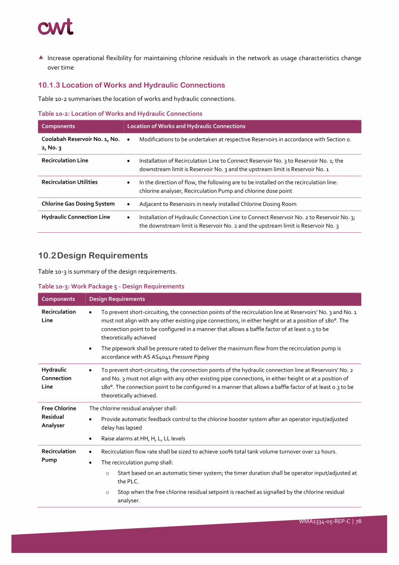
WMA1334-05-REP-C │ 78
Increase operational flexibility for maintaining chlorine residuals in the network as usage characteristics change
over time
10.1.3 Location of Works and Hydraulic Connections
Table 10-2 summarises the location of works and hydraulic connections.
Table 10-2: Location of Works and Hydraulic Connections
Components Location of Works and Hydraulic Connections
Coolabah Reservoir No. 1, No.
2, No. 3
• Modifications to be undertaken at respective Reservoirs in accordance with Section 0.
Recirculation Line • Installation of Recirculation Line to Connect Reservoir No. 3 to Reservoir No. 1; the
downstream limit is Reservoir No. 3 and the upstream limit is Reservoir No. 1
Recirculation Utilities • In the direction of flow, the following are to be installed on the recirculation line:
chlorine analyser, Recirculation Pump and chlorine dose point
Chlorine Gas Dosing System • Adjacent to Reservoirs in newly installed Chlorine Dosing Room
Hydraulic Connection Line • Installation of Hydraulic Connection Line to Connect Reservoir No. 2 to Reservoir No. 3;
the downstream limit is Reservoir No. 2 and the upstream limit is Reservoir No. 3
10.2 Design Requirements
Table 10-3 is summary of the design requirements.
Table 10-3: Work Package 5 - Design Requirements
Components Design Requirements
Recirculation
Line
• To prevent short-circuiting, the connection points of the recirculation line at Reservoirs’ No. 3 and No. 1
must not align with any other existing pipe connections, in either height or at a position of 180°. The
connection point to be configured in a manner that allows a baffle factor of at least 0.3 to be
theoretically achieved
• The pipework shall be pressure rated to deliver the maximum flow from the recirculation pump is
accordance with AS AS4041 Pressure Piping
Hydraulic
Connection
Line
• To prevent short-circuiting, the connection points of the hydraulic connection line at Reservoirs’ No. 2
and No. 3 must not align with any other existing pipe connections, in either height or at a position of
180°. The connection point to be configured in a manner that allows a baffle factor of at least 0.3 to be
theoretically achieved.
Free Chlorine
Residual
Analyser
The chlorine residual analyser shall:
• Provide automatic feedback control to the chlorine booster system after an operator input/adjusted
delay has lapsed
• Raise alarms at HH, H, L, LL levels
Recirculation
Pump
• Recirculation flow rate shall be sized to achieve 100% total tank volume turnover over 12 hours.
• The recirculation pump shall:
o Start based on an automatic timer system; the timer duration shall be operator input/adjusted at
the PLC.
o Stop when the free chlorine residual setpoint is reached as signalled by the chlorine residual
analyser.
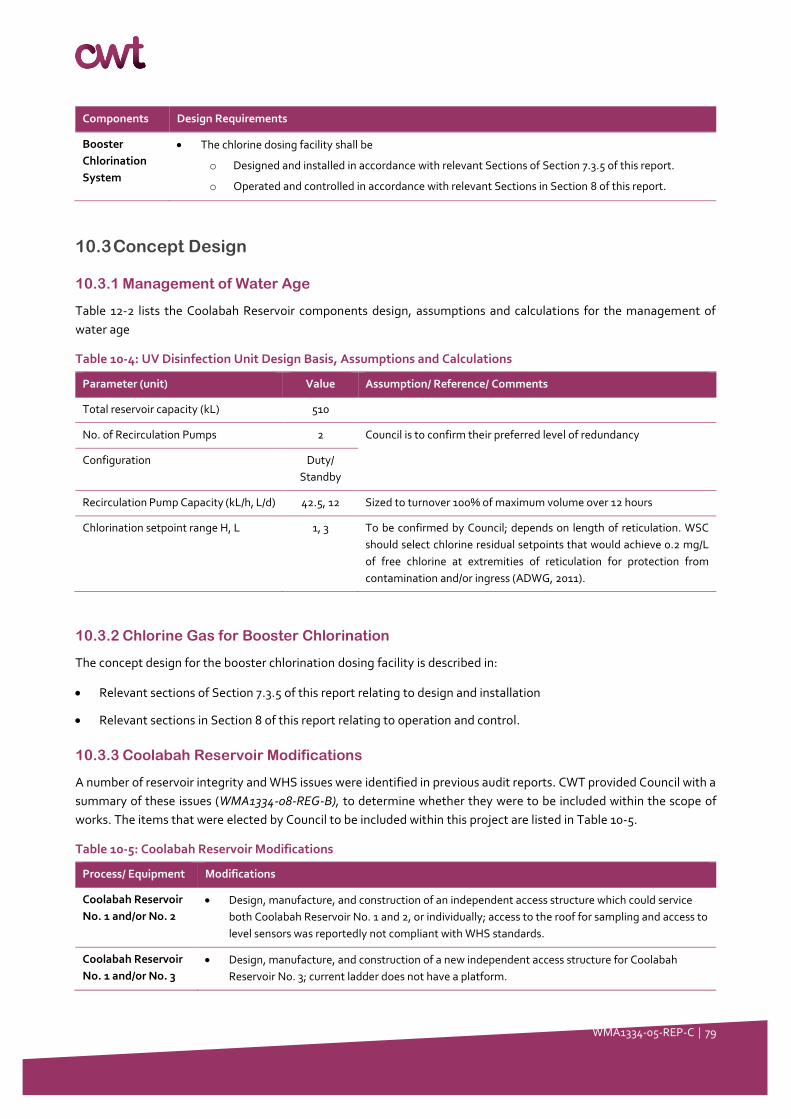
WMA1334-05-REP-C │ 79
Components Design Requirements
Booster
Chlorination
System
• The chlorine dosing facility shall be
o Designed and installed in accordance with relevant Sections of Section 7.3.5 of this report.
o Operated and controlled in accordance with relevant Sections in Section 8 of this report.
10.3 Concept Design
10.3.1 Management of Water Age
Table 12-2 lists the Coolabah Reservoir components design, assumptions and calculations for the management of
water age
Table 10-4: UV Disinfection Unit Design Basis, Assumptions and Calculations
Parameter (unit) Value Assumption/ Reference/ Comments
Total reservoir capacity (kL) 510
No. of Recirculation Pumps 2 Council is to confirm their preferred level of redundancy
Configuration Duty/
Standby
Recirculation Pump Capacity (kL/h, L/d) 42.5, 12 Sized to turnover 100% of maximum volume over 12 hours
Chlorination setpoint range H, L 1, 3 To be confirmed by Council; depends on length of reticulation. WSC
should select chlorine residual setpoints that would achieve 0.2 mg/L
of free chlorine at extremities of reticulation for protection from
contamination and/or ingress (ADWG, 2011).
10.3.2 Chlorine Gas for Booster Chlorination
The concept design for the booster chlorination dosing facility is described in:
• Relevant sections of Section 7.3.5 of this report relating to design and installation
• Relevant sections in Section 8 of this report relating to operation and control.
10.3.3 Coolabah Reservoir Modifications
A number of reservoir integrity and WHS issues were identified in previous audit reports. CWT provided Council with a
summary of these issues (WMA1334-08-REG-B), to determine whether they were to be included within the scope of
works. The items that were elected by Council to be included within this project are listed in Table 10-5.
Table 10-5: Coolabah Reservoir Modifications
Process/ Equipment Modifications
Coolabah Reservoir
No. 1 and/or No. 2
• Design, manufacture, and construction of an independent access structure which could service
both Coolabah Reservoir No. 1 and 2, or individually; access to the roof for sampling and access to
level sensors was reportedly not compliant with WHS standards.
Coolabah Reservoir
No. 1 and/or No. 3
• Design, manufacture, and construction of a new independent access structure for Coolabah
Reservoir No. 3; current ladder does not have a platform.

WMA1334-05-REP-C │ 80
11 Work Package 6: Replacement of Sludge Lagoons
with Clarifier
11.1 Description of works
11.1.1 Overview
The following table is an excerpt of Table 3-1 is summarises the activities to be addressed in this Section of the Report.
Table 11-1: Scope of Works and Activities
No. Work packages Activities
WP6 Replacement of Sludge
Lagoons with Clarification
• Concept design for:
o Replacement of Sedimentation Lagoons with Clarifier
o Reconfiguration of Sedimentation Lagoons to Sludge Lagoons
o Reconfiguration of filter backwash waste to Lagoons
o Implementation of filter-to-waste line
o Installation of supernatant return facilities
A Preliminary Hazard Assessment (PHA) facilitated by CWT (Jess Circosta, Christina Saxvik) on the 14th and 20th of May
2020 found that WSC’s proposed upgrades works were not sufficient to mitigate identified risks at the Sludge Lagoons
to an acceptable level. Algae and their toxins (see Section 2.6.3), faecal contamination by birds and environmental
runoff were identified as key hazards which could not be reduced to an acceptable level by the existing measures, even
with improved operation or upgrades to the upstream infrastructure.
It is recommendation that the existing Sludge Lagoons are replaced by a Clarifier to exclude algae-favouring conditions
and introduced contaminants from the environment.
11.1.2 Process Description
Flocculated water from the Flocculation Tank would gravitate to a
Clarifier.
At the Clarifier, sludge would be drawn out intermittently on timer via
duty/ standby Clarifier Sludge Pumps and transferred to Sludge
Lagoons. The existing Sedimentation Lagoons may serve as these
Sludge Lagoons.
Clarified water would pass into the launders and to the outlet of the
Clarifier where it will be collected at the Low Lift Pump Station and
pumped to the filters.
The Sludge Lagoons would be operated in duty/standby and alternated
every 6 months to 1 year for desludging purposes.
From the Sludge Holding Lagoons, supernatant shall gravitate to a
Supernatant Return Well where it can be returned to the Blending Tank
at the head of the works via a duty Supernatant Return Pump at a rate
not exceeding 10% of the plant’s instantaneous flow.
Council may also opt to use supernatant for onsite irrigation purposes.
Figure 11-1 Example of Inclined Plate 200
GPM Clarifier (HydroFlow, 2020)

WMA1334-05-REP-C │ 81
Backwash water from the filters shall be redirected to the Sludge Lagoons (rather than the Flocculation Tank as per
the current configuration). Pipework and valves at the discharge side of the filters shall direct first pass water upon
plant start up to a filter-to-waste line. This filter-to-waste line shall extend to the Sludge Lagoons.
11.1.3 Location of Works
Table 11-2 provides a summary of the key process components included in this package of works and their location for
instalment.
Table 11-2: Location of Works
Components Location of Works
Clarifier Adjacent to existing Sludge Lagoons; downstream of the Flocculation Tank and upstream of the Low
Lift Pump Station
Sludge Pump(s) Adjacent to the Clarifier; downstream of the Clarifier and upstream of the Sludge Lagoons
Sludge Lagoons At existing Sedimentation Lagoons; existing Sedimentation Lagoons to be repurposed as Sludge
Lagoons
Supernatant Return
Well
Within a pit at the outlet the Sludge Lagoons; downstream of the Sludge Lagoons and upstream of
the Blending Tank
Supernatant Return
Pump
Either submerged or adjacent to/in the Supernatant Return Well; downstream of the Sludge Lagoons
and upstream of the Blending Tank
Filter Backwash Line At the feed side of the existing filters and extending to the Sludge Lagoons
Filter-to-Waste Line At the discharge side of the existing filters and extending to the Sludge Lagoons
11.2 Design Requirements
Table 11-3 is summary of the design requirements.
Table 11-3: Summary of Design Requirements
Components Design Requirements
Clarifier • Designed for loading rate of:
o 5 m/h for circular clarifier
o 1.5 m/h for tube settler or lamella plate clarifier
Clarifier Sludge Pump • Duty/ standby arrangement
Sludge Lagoons • Duty/ standby arrangement alternated every 6-12 months
Supernatant Return Well • Capacity of pit is sized to contain the volume of:
o 2 × filter backwash volumes based on backwash pump capacity of 68.2 kL/h and
backwash duration of 10 minutes per filter
o Clarifier sludge production of 10 minutes with flowrate based on 10% of total
plant flows
o Plus 10% for overflows
Supernatant Return Pump • Duty or duty/ standby arrangement (as per Council’s preference) fitted with VSD
• Return supernatant f0lows to head of works to be limited to 10% of incoming raw
water flows to the plant as measured by the common raw water flowmeter.

WMA1334-05-REP-C │ 82
11.3 Concept Design Calculations
The equipment sizing shall depend on the elected design basis. The existing components of the plant, and in particular
the raw water pumps are sized to deliver up to 1 ML/d. However, as discussed in Section 4.2.2of this report, the daily
demand infrequently exceeds 0.424 ML/d. The following sizing requirements are given for the 0.424 ML/d (over 16
h/day) and 1 ML/d (over 22 h/d).
Table 11-4: Clarifier Design Basis, Assumptions and Calculations
Component/
Option
Parameter (unit) 95-%ile – 0.424
ML/d
Design –
1.00 ML/d
Assumption/ Reference/ Comment
Circular
clarifier option
Loading rate (m/h) 1.5 1.5 WIOA (2008) Practical Guide to
Coagulation, Flocculation and
Clarification; Clarification loading rate
of 1.5 m/h is targeted for Circular
Clarifiers, a clarification rate of 5 m/h is
targeted for lamella plate or tube
settler clarifiers.
Surface area of Clarifier (m2) 17.7 30.3
Diameter of Clarifier (m) 4.7 6.2
Lamella or
inclined plate
option
Loading rate (m/h) 5.0 5.0
Surface area of Clarifier (m2) 5.3 7.6
Diameter of Clarifier (m) 2.6 3.1
Clarifier Sludge
Pump
No. of pumps 2 2
Configuration Duty/standby Duty/standby
Capacity As per package specifications
Supernatant
Return Pit Capacity (kL) 25.5
Sized for 10 minutes of clarifier sludge
production at 10% of total plant flows +
the volume of 2 × 10- minute filter
backwashes at 68.2 kL/h.
Sludge
Lagoons Capacity (kL)
As per existing Sludge capacity requirements should
be confirmed during detailed design
Supernatant
Return Pump
No of pumps 1 1 Redundancy requirements to be
confirmed by Council Configuration Duty Duty
Capacity (kL/h) 2.7 4.6 10% of instantaneous raw water flows

WMA1334-05-REP-C │ 83
12 Work Package 8: Installation of UV Disinfection Unit
12.1 Description of Works
12.1.1 Overview
The following table is an excerpt of Table 3-1, and summarises the activities to be addressed in this Section of the
Report.
Table 12-1: Scope of Works and Activities
No. Work packages Activities
WP7 Installation of UV
Disinfection Unit
• Concept design for:
o UV Disinfection Unit
o UV transmissivity benchtop analyser
A Preliminary Hazard Assessment (PHA) facilitated by CWT (Jess Circosta, Christina Saxvik) on the 14th and 20th of May
2020 found that WSC’s proposed upgrades works were not sufficient to meet the new health-based log removal targets
for raw water sourced from a Category 4 catchment. Category 4 catchments are characterised as unprotected
catchments with agricultural and human activities in the catchment and the possible presence of septics. These
catchments attract health-based targets of 6.0-, 6.0- and 5.5-log reduction of bacteria, viruses and protozoa,
respectively.
Even with the proposed upgrades as described in the previous sections of this report, the WTP processes, even
optimised, would have a 2.5-log removal deficit for protozoa (see Table 4-6).
Therefore, it is recommended that an inline UV disinfection unit is installed at Mendooran WTP.
12.1.2 Process Description
From the 1 kL Filtered Water Tank, water would be pumped to an inline UV disinfection unit sized to deliver 40 mJ/cm2
for 4.0-, 0.5- and 4.0-log removal of bacteria, viruses and protozoa, respectively. The UV unit shall continuously monitor
UV intensity.
From the UV Disinfection Unit, water is to pass to the Clear Water Tank. En route, UV treated water is to be dosed with
chlorine solution for final disinfection and soda ash for pH and alkalinity correction (as required).
The UV transmissivity of filtered water shall be measured daily using a benchtop UVT analyser.
12.2 Design Requirements
The design requirements are as follows:
• The UV unit shall be sized to deliver a validated Reduction Equivalent Dose (RED) of 40 mJ/cm2 or a dose sufficient
to meet to log deficit for protozoa removal, as outlined by the Health Based Targets.
• The manufacturer’s stated operating envelop for water quality must be consistent with that of the filtered water
quality produced by the Mendooran WTP. Typically, this includes water of <1 NTU and with ≥85% UV
transmissivity.
• A benchtop UVT analyser shall be procured to verify that water being received at the UV unit is within the required
water quality envelop as set out in the manufacturer’s specifications.
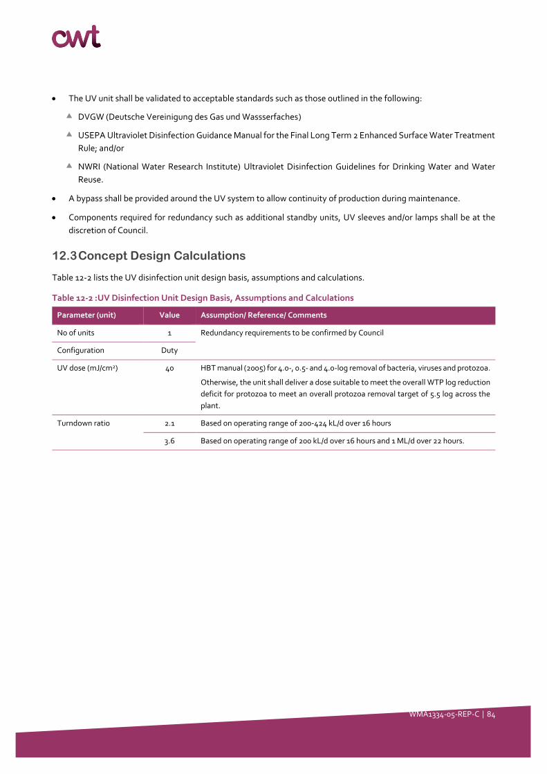
WMA1334-05-REP-C │ 84
• The UV unit shall be validated to acceptable standards such as those outlined in the following:
DVGW (Deutsche Vereinigung des Gas und Wassserfaches)
USEPA Ultraviolet Disinfection Guidance Manual for the Final Long Term 2 Enhanced Surface Water Treatment
Rule; and/or
NWRI (National Water Research Institute) Ultraviolet Disinfection Guidelines for Drinking Water and Water
Reuse.
• A bypass shall be provided around the UV system to allow continuity of production during maintenance.
• Components required for redundancy such as additional standby units, UV sleeves and/or lamps shall be at the
discretion of Council.
12.3 Concept Design Calculations
Table 12-2 lists the UV disinfection unit design basis, assumptions and calculations.
Table 12-2 :UV Disinfection Unit Design Basis, Assumptions and Calculations
Parameter (unit) Value Assumption/ Reference/ Comments
No of units 1 Redundancy requirements to be confirmed by Council
Configuration Duty
UV dose (mJ/cm2) 40 HBT manual (2005) for 4.0-, 0.5- and 4.0-log removal of bacteria, viruses and protozoa.
Otherwise, the unit shall deliver a dose suitable to meet the overall WTP log reduction
deficit for protozoa to meet an overall protozoa removal target of 5.5 log across the
plant.
Turndown ratio 2.1 Based on operating range of 200-424 kL/d over 16 hours
3.6 Based on operating range of 200 kL/d over 16 hours and 1 ML/d over 22 hours.
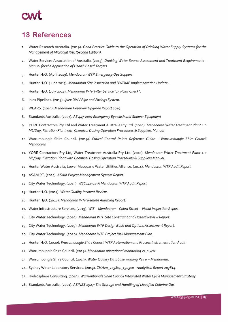
WMA1334-05-REP-C │ 85
13 References
1. Water Research Australia. (2019). Good Practice Guide to the Operation of Drinking Water Supply Systems for the
Management of Microbial Risk (Second Edition).
2. Water Services Association of Australia. (2015). Drinking Water Source Assessment and Treatment Requirements -
Manual for the Application of Health Based Targets.
3. Hunter H2O. (April 2019). Mendooran WTP Emergency Ops Support.
4. Hunter H2O. (June 2017). Mendooran Site Inspection and DWQMP Implementation Update.
5. Hunter H2O. (July 2018). Mendooran WTP Filter Service “15 Point Check”.
6. Iplex Pipelines. (2013). Iplex DWV Pipe and Fittings System.
7. WEARS. (2019). Mendooran Reservoir Upgrade Report 2019.
8. Standards Australia. (2007). AS 447-2007 Emergency Eyewash and Shower Equipment
9. YORE Contractors Pty Ltd and Water Treatment Australia Pty Ltd. (2010). Mendooran Water Treatment Plant 1.0
ML/Day, Filtration Plant with Chemical Dosing Operation Procedures & Suppliers Manual
10. Warrumbungle Shire Council. (2019). Critical Control Points Reference Guide – Warrumbungle Shire Council
Mendooran
11. YORE Contractors Pty Ltd, Water Treatment Australia Pty Ltd. (2010). Mendooran Water Treatment Plant 1.0
ML/Day, Filtration Plant with Chemical Dosing Operation Procedures & Suppliers Manual.
12. Hunter Water Australia, Lower Macquarie Water Utilities Alliance. (2014). Mendooran WTP Audit Report.
13. ASAM RT. (2014). ASAM Project Management System Report.
14. City Water Technology. (2015). WSC742-02-A Mendooran WTP Audit Report.
15. Hunter H2O. (2017). Water Quality Incident Review.
16. Hunter H2O. (2018). Mendooran WTP Remote Alarming Report.
17. Water Infrastructure Services. (2019). WIS – Mendooran – Cobra Street – Visual Inspection Report
18. City Water Technology. (2019). Mendooran WTP Site Constraint and Hazard Review Report.
19. City Water Technology. (2019). Mendooran WTP Design Basis and Options Assessment Report.
20. City Water Technology. (2020). Mendooran WTP Project Risk Management Plan.
21. Hunter H2O. (2020). Warrumbungle Shire Council WTP Automation and Process Instrumentation Audit.
22. Warrumbungle Shire Council. (2019). Mendooran operational monitoring v2.0.xlsx.
23. Warrumbungle Shire Council. (2019). Water Quality Database working Rev 0 – Mendooran.
24. Sydney Water Laboratory Services. (2019). ZHH20_203814_190510 - Analytical Report 203814.
25. Hydrosphere Consulting. (2019). Warrumbungle Shire Council Integrated Water Cycle Management Strategy.
26. Standards Australia. (2001). AS/NZS 2927: The Storage and Handling of Liquefied Chlorine Gas.
WMA1334-05-REP-C │ 86
27. Standards Australia. (2007). AS 4775-2007 Emergency Eyewash and Shower Equipment.
28. Standards Australia. (2010). AS 2845.1-2010 Water Supply – Backflow Prevention Devices.
29. Standards Australia. (2001). AS 2444-2001 Potable Fire Extinguishers and Fire Blankets.
30. Standards Australia. (2008). AS 3780-2008 The storage and handling of corrosive substances.
31. Standards Australia. (2008). AS 4326-2008 The storage and handling of oxidizing agents.
32. Standards Australia. (2007). AS NZS 3000-2007 Wiring rules.
33. Standards Australia. (2015). AS/NZS 3500.1:2015 Plumbing and Drainage.
34. Standards Australia. (1999). AS 4037 1999 Pressure Equipment – Examination and Testing.
35. Standards Australia. (2006). AS 4041 2006 Pressure Piping.
36. Standards Australia. AS 4037 Standard Hydrostatic Pressure Test Records.
37. Standards Australia. (2008). AS/NZS 2033:2008 Installation of polyethylene pipe systems.
38. Standards Australia. (2006). AS 4032 2006 Installation of PVC pipe systems.
39. Standards Australia. (2002). AS 2566.2-2002 Buried flexible lines.
40. Deutsche Vereinigung des Gas und Wassserfaches (DVGW). Various standards.
41. United States Environmental Protection Agency (USEPA). (2006). Ultraviolet Disinfection Guidance Manual for the
Final Long Term 2 Enhanced Surface Water Treatment Rule.
42. National Water Research Institute (NWRI). (2012). Ultraviolet Disinfection Guidelines for Drinking Water and Water
Reuse.