menges/michaeli/mohren · georg menges walter michaeli paul mohren how to make injection molds...
TRANSCRIPT


Menges/Michaeli/MohrenHow to Make Injection Molds


Georg MengesWalter MichaeliPaul Mohren
How to MakeInjection MoldsThird Edition
Hanser Publishers, Munich
Hanser Gardner Publications, Inc., Cincinnati

Translated and revised edition of“Anleitung zum Bau von Spritzgießwerkzeugen”, 5th Edition, 1999by Prof. Dr.-Ing. Georg Menges, Prof. Dr.-Ing. Walter Michaeli and Ing. Paul Mohren,Institut für Kunststoffverarbeitung in Industrie und Handwerkan der Rhein.-Westf. Technischen Hochschule Aachen(Institute for Plastics Processing, Technical University of Aachen)
Translated by Rolf J. Kahl and Raymond Brown
Distributed in the USA and in Canada byHanser Gardner Publications, Inc.6915 Valley Ave.Cincinnati, OH 45244, USAFax: +1 (513) 527 8950http://www.hansergardner.com
Distributed in all other countries by Carl Hanser VerlagPostfach 86 04 20, 81631 München, GermanyFax: +49 (89) 99 830-269http://hanser.de
Library of Congress Cataloging-in-Publication Data
Menges, Georg, 1923–[Anleitung zum Bau von Spritzgiesswerkzeugen. English]How to make injection molds. – 3rd ed. / Georg Menges, Walter Michaeli, Paul Mohren;[translated by Rolf J. Kahl and Raymond Brown].
p. cmIncludes bibliographical references and index.ISBN: 1-56990-282-81. Injection molding of plastics. I. Michaeli, Walter. II. Mohren, Paul. III. Title.
TP1150.M3813 2000668.4’12–dc21 00-046238
Die Deutsche Bibliothek – CIP-Einheitsaufnahme
Menges, Georg:How to make injection molds / Georg Menges ; Walter Michaeli ; Paul Mohren. [Transl. by Rolf J. Kahland Raymond Brown]. – 3. ed.. – Munich : Hanser; Cincinnati : Hanser Gardner, 2000Einheitssacht.: Anleitung für den Bau von Spritzgießwerkzeugen <engl.>ISBN: 3-446-21256-6
The use of general descriptive names, trademarks, etc. in this publication, even if the former are notespecially identified, is not to be taken as a sign that such names, as understood by the Trade Marks andMerchandise Marks Act, may accordingly be used freely by anyone.While the advice and information in this book are believed to be true and accurate at the date of goingto press, neither the authors nor the editors nor the publisher can accept any legal responsibility for anyerrors or omissions that may be made. The publisher makes no warranty, express or implied, with respectto the material contained herein.
All right reserved. No part of this book may be reproduced or transmitted in any form or by any means,electronic or mechanical, including photocopying or by any information storage and retrieval system,without permission in writing from the publisher.Copyright „ Carl Hanser Verlag, Munich, 2001Typesetting by Cicero Lasersatz, GermanyPrinted in Germany by Kösel

Preface to the 3rd Edition
Injection molds are high-precision tools whose smooth-operation on a day-to-day basisis vital to the economic success of many plastics processors. Consequently, errors indesign and construction of molds can have grave consequences.
That is where this book comes in. Building on the earlier editions, it draws extensi-vely both on the literature and on the development work carried out at the Institute forPlastics Processing in the Technical University of Aachen with the aid of substantial pri-vate and public research funding.
We are especially grateful to those who participated in this edition and to those wholaid the foundations for it in earlier editions, namely Dr. H. Bangert, Dr. P. Barth, Dr. W.Hoven-Nievelstein, Dr. O. Kretschmar, Dr. M. Paar, Dr. G. Pötsch, Dr. Th. W. Schmidt.,Dr. Ch. Schneider, Prof. E. Schürmann and Prof. S. Stitz.
We are indebted to the co-workers and students in the institute who contributed to thesuccess of this book through their unstinting work and their personal commitment. Asthey are too numerous to mention, we trust that Ms. G. Nelissen, Ms. I. Zekorn and Mr.W. Okon will accept our thanks on their behalf. Finally, we extend our appreciation toCarl Hanser Verlag, and especially to Dr. W. Glenz and Mr. O. Immel, for taking themanuscript and turning it into such a distinctive and attractive book.
G. MengesW. MichaeliP. Mohren

Contents
1 Materials for Injection Molds . . . . . . . . . . . . . . . . . . . . . . . . . . . . . . . . . . . . 11.1 Steels . . . . . . . . . . . . . . . . . . . . . . . . . . . . . . . . . . . . . . . . . . . . . . . . . . . 2
1.1.1 Summary . . . . . . . . . . . . . . . . . . . . . . . . . . . . . . . . . . . . . . . . . . . 21.1.2 Case-Hardening Steels . . . . . . . . . . . . . . . . . . . . . . . . . . . . . . . . . 61.1.3 Nitriding Steels . . . . . . . . . . . . . . . . . . . . . . . . . . . . . . . . . . . . . . 71.1.4 Through-Hardening Steels . . . . . . . . . . . . . . . . . . . . . . . . . . . . . . 71.1.5 Heat-Treated Steels . . . . . . . . . . . . . . . . . . . . . . . . . . . . . . . . . . . 91.1.6 Martensitic Steels . . . . . . . . . . . . . . . . . . . . . . . . . . . . . . . . . . . . . 101.1.7 Hard Mold Alloys. . . . . . . . . . . . . . . . . . . . . . . . . . . . . . . . . . . . . 101.1.8 Corrosion-Resistant Steels . . . . . . . . . . . . . . . . . . . . . . . . . . . . . . 101.1.9 Refined Steels . . . . . . . . . . . . . . . . . . . . . . . . . . . . . . . . . . . . . . . 11
1.2 Cast Steel . . . . . . . . . . . . . . . . . . . . . . . . . . . . . . . . . . . . . . . . . . . . . . . . 121.3 Nonferrous Metallics . . . . . . . . . . . . . . . . . . . . . . . . . . . . . . . . . . . . . . . 12
1.3.1 Copper Alloys . . . . . . . . . . . . . . . . . . . . . . . . . . . . . . . . . . . . . . . 121.3.1.1 Beryllium-Copper Alloys . . . . . . . . . . . . . . . . . . . . . . . . 13
1.3.2 Zinc and its Alloys . . . . . . . . . . . . . . . . . . . . . . . . . . . . . . . . . . . . 141.3.3 Aluminum Alloys . . . . . . . . . . . . . . . . . . . . . . . . . . . . . . . . . . . . . 161.3.4 Bismuth-Tin Alloys . . . . . . . . . . . . . . . . . . . . . . . . . . . . . . . . . . . 18
1.4 Materials for Electrolytic Deposition. . . . . . . . . . . . . . . . . . . . . . . . . . . . 191.5 Surface Treatment of Steels for Injection Molds . . . . . . . . . . . . . . . . . . . 20
1.5.1 General Information . . . . . . . . . . . . . . . . . . . . . . . . . . . . . . . . . . . 201.5.2 Heat Treatment of Steels . . . . . . . . . . . . . . . . . . . . . . . . . . . . . . . 211.5.3 Thermochemical Treatment Methods . . . . . . . . . . . . . . . . . . . . . . 21
1.5.3.1 Carburizing . . . . . . . . . . . . . . . . . . . . . . . . . . . . . . . . . . 211.5.3.2 Nitriding. . . . . . . . . . . . . . . . . . . . . . . . . . . . . . . . . . . . . 221.5.3.3 Boriding . . . . . . . . . . . . . . . . . . . . . . . . . . . . . . . . . . . . . 22
1.5.4 Electrochemical Treatments . . . . . . . . . . . . . . . . . . . . . . . . . . . . . 231.5.4.1 Chrome Plating. . . . . . . . . . . . . . . . . . . . . . . . . . . . . . . . 231.5.4.2 Nickel Plating. . . . . . . . . . . . . . . . . . . . . . . . . . . . . . . . . 231.5.4.3 NYE-CARD Process . . . . . . . . . . . . . . . . . . . . . . . . . . . 241.5.4.4 Hard Alloy Coating . . . . . . . . . . . . . . . . . . . . . . . . . . . . 24
1.5.5 Coating at Reduced Pressure . . . . . . . . . . . . . . . . . . . . . . . . . . . . 241.5.5.1 CVD Process . . . . . . . . . . . . . . . . . . . . . . . . . . . . . . . . . 241.5.5.2 PVD Process . . . . . . . . . . . . . . . . . . . . . . . . . . . . . . . . . 25
1.6 Laser Surface Treatment . . . . . . . . . . . . . . . . . . . . . . . . . . . . . . . . . . . . . 261.6.1 Laser Hardening and Re-Melting . . . . . . . . . . . . . . . . . . . . . . . . . 271.6.2 Laser Alloying, Dispersing, and Coating. . . . . . . . . . . . . . . . . . . . 27
1.7 Electron Beam Hardening . . . . . . . . . . . . . . . . . . . . . . . . . . . . . . . . . . . . 281.8 Lamcoat Coating. . . . . . . . . . . . . . . . . . . . . . . . . . . . . . . . . . . . . . . . . . . 28References . . . . . . . . . . . . . . . . . . . . . . . . . . . . . . . . . . . . . . . . . . . . . . . . . . . 28

VIII Contents
2 Mold Making Techniques . . . . . . . . . . . . . . . . . . . . . . . . . . . . . . . . . . . . . . . 312.1 Production of Metallic Injection Molds and Mold Inserts by Casting . . . . 32
2.1.1 Casting Methods and Cast Alloys . . . . . . . . . . . . . . . . . . . . . . . . . 322.1.2 Sand Casting . . . . . . . . . . . . . . . . . . . . . . . . . . . . . . . . . . . . . . . . 332.1.3 Precision Casting Techniques . . . . . . . . . . . . . . . . . . . . . . . . . . . . 35
2.2 Rapid Tooling for Injection Molds . . . . . . . . . . . . . . . . . . . . . . . . . . . . . 352.2.1 State of the Art . . . . . . . . . . . . . . . . . . . . . . . . . . . . . . . . . . . . . . . 372.2.2 Direct Rapid Tooling . . . . . . . . . . . . . . . . . . . . . . . . . . . . . . . . . . 39
2.2.2.1 Direct Fabrication of Metallic Molds . . . . . . . . . . . . . . . 392.2.2.1.1 Generative Methods. . . . . . . . . . . . . . . . . . . . 392.2.2.1.2 Direct Fabrication of Nonmetallic Molds . . . . 42
2.2.3 Indirect Rapid Tooling (Multistage Process Chains) . . . . . . . . . . . 432.2.3.1 Process Chains Involving a Positive Pattern . . . . . . . . . . 442.2.3.2 Process Chains Involving a Negative Pattern . . . . . . . . . 46
2.2.4 Outlook . . . . . . . . . . . . . . . . . . . . . . . . . . . . . . . . . . . . . . . . . . . . 502.3 Hobbing . . . . . . . . . . . . . . . . . . . . . . . . . . . . . . . . . . . . . . . . . . . . . . . . . 502.4 Machining and Other Material Removing Operations . . . . . . . . . . . . . . . 54
2.4.1 Machining Production Methods . . . . . . . . . . . . . . . . . . . . . . . . . . 542.4.2 Surface Treatment (Finishing) . . . . . . . . . . . . . . . . . . . . . . . . . . . 55
2.4.2.1 Grinding and Polishing (Manual or Assisted) . . . . . . . . . 552.4.2.2 Vibratory Grinding . . . . . . . . . . . . . . . . . . . . . . . . . . . . . 562.4.2.3 Sand Blasting (Jet Lapping) . . . . . . . . . . . . . . . . . . . . . . 562.4.2.4 Pressure Lapping . . . . . . . . . . . . . . . . . . . . . . . . . . . . . . 572.4.2.5 Electrochemical Polishing. . . . . . . . . . . . . . . . . . . . . . . . 572.4.2.6 Electric-Discharge Polishing. . . . . . . . . . . . . . . . . . . . . . 57
2.5 Electric-Discharge Forming Processes. . . . . . . . . . . . . . . . . . . . . . . . . . . 592.5.1 Electric-Discharge Machining (EDM). . . . . . . . . . . . . . . . . . . . . . 592.5.2 Cutting by Spark Erosion with Traveling-Wire Electrodes . . . . . . 62
2.6 Electrochemical Machining (ECM) . . . . . . . . . . . . . . . . . . . . . . . . . . . . . 632.7 Electrochemical Material Removal-Etching. . . . . . . . . . . . . . . . . . . . . . . 632.8 Surfaces Processed by Spark Erosion or Chemical Dissolution (Etching). 652.9 Laser Carving . . . . . . . . . . . . . . . . . . . . . . . . . . . . . . . . . . . . . . . . . . . . . 67
2.9.1 Rapid Tooling with LASERCAV . . . . . . . . . . . . . . . . . . . . . . . . . 682.10 Molds for the Fusible-Core Technique. . . . . . . . . . . . . . . . . . . . . . . . . . . 68
2.10.1 Molds for Sheathing the Fusible Cores . . . . . . . . . . . . . . . . . . . . . 712.10.1.1 Gating the Molding . . . . . . . . . . . . . . . . . . . . . . . . . . . . 742.10.1.2 Thermal Considerations Concerning Mold Design . . . . . 742.10.1.3 Core Shifting . . . . . . . . . . . . . . . . . . . . . . . . . . . . . . . . . 752.10.1.4 Venting. . . . . . . . . . . . . . . . . . . . . . . . . . . . . . . . . . . . . . 75
2.10.2 Molds for Making the Fusible Cores. . . . . . . . . . . . . . . . . . . . . . . 772.10.2.1 Core Material . . . . . . . . . . . . . . . . . . . . . . . . . . . . . . . . . 782.10.2.2 Construction of a Casting Mold . . . . . . . . . . . . . . . . . . . 782.10.2.3 Gating Systems. . . . . . . . . . . . . . . . . . . . . . . . . . . . . . . . 782.10.2.4 Thermal Considerations Concerning the Core-Casting
Mold . . . . . . . . . . . . . . . . . . . . . . . . . . . . . . . . . . . . . . . 802.10.2.5 Demolding Cast Fusible Cores . . . . . . . . . . . . . . . . . . . . 81
References . . . . . . . . . . . . . . . . . . . . . . . . . . . . . . . . . . . . . . . . . . . . . . . . . . . 81

IXContents
3 Procedure for Estimating Mold Costs . . . . . . . . . . . . . . . . . . . . . . . . . . . . . 853.1 General Outline . . . . . . . . . . . . . . . . . . . . . . . . . . . . . . . . . . . . . . . . . . . 853.2 Procedures for Estimating Mold Costs . . . . . . . . . . . . . . . . . . . . . . . . . . 853.3 Cost Group I: Cavity. . . . . . . . . . . . . . . . . . . . . . . . . . . . . . . . . . . . . . . . 88
3.3.1 Computation of Working Hours for Cavities . . . . . . . . . . . . . . . . . 893.3.2 Time Factor for Machining Procedure . . . . . . . . . . . . . . . . . . . . . 903.3.3 Machine Time for Cavity Depth . . . . . . . . . . . . . . . . . . . . . . . . . . 903.3.4 Time Consumption for Cavity Surface . . . . . . . . . . . . . . . . . . . . . 913.3.5 Time Factor for Parting Line . . . . . . . . . . . . . . . . . . . . . . . . . . . . 923.3.6 Time Factor for Surface Quality . . . . . . . . . . . . . . . . . . . . . . . . . . 923.3.7 Machining Time for Fixed Cores . . . . . . . . . . . . . . . . . . . . . . . . . 923.3.8 Time Factor for Tolerances . . . . . . . . . . . . . . . . . . . . . . . . . . . . . . 933.3.9 Time Factor for Degree of Difficulty
and Multifariousness . . . . . . . . . . . . . . . . . . . . . . . . . . . . . . . . . . 933.3.10 Time Factor for Number of Cavities . . . . . . . . . . . . . . . . . . . . . . . 943.3.11 Computation of Working Hours for EDM Electrodes . . . . . . . . . . 94
3.4 Cost Group II: Basic Molds . . . . . . . . . . . . . . . . . . . . . . . . . . . . . . . . . . 953.5 Cost Group III: Basic Functional Components. . . . . . . . . . . . . . . . . . . . . 96
3.5.1 Sprue and Runner System. . . . . . . . . . . . . . . . . . . . . . . . . . . . . . . 963.5.2 Runner System. . . . . . . . . . . . . . . . . . . . . . . . . . . . . . . . . . . . . . . 983.5.3 Hot-Runner Systems. . . . . . . . . . . . . . . . . . . . . . . . . . . . . . . . . . . 983.5.4 Heat-Exchange System. . . . . . . . . . . . . . . . . . . . . . . . . . . . . . . . . 983.5.5 Ejector System . . . . . . . . . . . . . . . . . . . . . . . . . . . . . . . . . . . . . . . 99
3.6 Cost Group IV: Special Functions . . . . . . . . . . . . . . . . . . . . . . . . . . . . . . 993.7 Other Cost Calculation Methods . . . . . . . . . . . . . . . . . . . . . . . . . . . . . . . 100
3.7.1 Costs Based on Similarity Considerations. . . . . . . . . . . . . . . . . . . 1003.7.2 The Principle behind Hierarchical Similarity Searching . . . . . . . . 103
References . . . . . . . . . . . . . . . . . . . . . . . . . . . . . . . . . . . . . . . . . . . . . . . . . . . 103
4 The Injection Molding Process . . . . . . . . . . . . . . . . . . . . . . . . . . . . . . . . . . . 1054.1 Cycle Sequence in Injection Molding . . . . . . . . . . . . . . . . . . . . . . . . . . . 105
4.1.1 Injection Molding of Thermoplastics . . . . . . . . . . . . . . . . . . . . . . 1074.1.2 Injection Molding of Crosslinkable Plastics . . . . . . . . . . . . . . . . . 107
4.1.2.1 Injection Molding of Elastomers . . . . . . . . . . . . . . . . . . . 1084.1.2.2 Injection Molding of Thermosets . . . . . . . . . . . . . . . . . . 108
4.2 Terms Used in Connection with Injection Molds . . . . . . . . . . . . . . . . . . . 1094.3 Classification of Molds . . . . . . . . . . . . . . . . . . . . . . . . . . . . . . . . . . . . . . 1094.4 Functions of the Injection Mold . . . . . . . . . . . . . . . . . . . . . . . . . . . . . . . 110
4.4.1 Criteria for Classification of Molds . . . . . . . . . . . . . . . . . . . . . . . 1114.4.2 Basic Procedure for Mold Design . . . . . . . . . . . . . . . . . . . . . . . . . 1154.4.3 Determination of Mold Size . . . . . . . . . . . . . . . . . . . . . . . . . . . . . 115
4.4.3.1 Maximum Number of Cavities . . . . . . . . . . . . . . . . . . . . 1154.4.3.2 Clamping Force . . . . . . . . . . . . . . . . . . . . . . . . . . . . . . . 1214.4.3.3 Maximum Clamping Area. . . . . . . . . . . . . . . . . . . . . . . . 1214.4.3.4 Required Opening Stroke . . . . . . . . . . . . . . . . . . . . . . . . 121
4.4.4 The Flow Length/Wall Thickness Ratio . . . . . . . . . . . . . . . . . . . . 1224.4.5 Computation of Number of Cavities . . . . . . . . . . . . . . . . . . . . . . . 123
4.4.5.1 Algorithm for the Determination of the Technically and Economically Optimum Number of Cavities . . . . . . 127

X Contents
4.4.5.2 Costs for Sampling, Setup, and Maintenance . . . . . . . . . 1364.5 Cavity Layouts . . . . . . . . . . . . . . . . . . . . . . . . . . . . . . . . . . . . . . . . . . . . 138
4.5.1 General Requirements . . . . . . . . . . . . . . . . . . . . . . . . . . . . . . . . . 1384.5.2 Presentation of Possible Solutions . . . . . . . . . . . . . . . . . . . . . . . . 1394.5.3 Equilibrium of Forces in a Mold During Injection . . . . . . . . . . . . 1394.5.4 Number of Parting Lines . . . . . . . . . . . . . . . . . . . . . . . . . . . . . . . 140
References . . . . . . . . . . . . . . . . . . . . . . . . . . . . . . . . . . . . . . . . . . . . . . . . . . . 141
5 Design of Runner Systems . . . . . . . . . . . . . . . . . . . . . . . . . . . . . . . . . . . . . . 1435.1 Characterization of the Complete Runner System . . . . . . . . . . . . . . . . . . 1435.2 Concept and Definition of Various Types of Runners. . . . . . . . . . . . . . . . 144
5.2.1 Standard Runner Systems . . . . . . . . . . . . . . . . . . . . . . . . . . . . . . . 1445.2.2 Hot-Runner Systems. . . . . . . . . . . . . . . . . . . . . . . . . . . . . . . . . . . 1445.2.3 Cold-Runner Systems. . . . . . . . . . . . . . . . . . . . . . . . . . . . . . . . . . 144
5.3 Demands on the Runner System . . . . . . . . . . . . . . . . . . . . . . . . . . . . . . . 1455.4 Classification of Runner Systems . . . . . . . . . . . . . . . . . . . . . . . . . . . . . . 1465.5 The Sprue . . . . . . . . . . . . . . . . . . . . . . . . . . . . . . . . . . . . . . . . . . . . . . . . 1465.6 Design of Runners . . . . . . . . . . . . . . . . . . . . . . . . . . . . . . . . . . . . . . . . . 1515.7 Design of Gates . . . . . . . . . . . . . . . . . . . . . . . . . . . . . . . . . . . . . . . . . . . 152
5.7.1 Position of the Gate at the Part . . . . . . . . . . . . . . . . . . . . . . . . . . . 1565.8 Runners and Gates for Reactive Materials . . . . . . . . . . . . . . . . . . . . . . . . 161
5.8.1 Elastomers . . . . . . . . . . . . . . . . . . . . . . . . . . . . . . . . . . . . . . . . . . 1615.8.2 Thermosets. . . . . . . . . . . . . . . . . . . . . . . . . . . . . . . . . . . . . . . . . . 1625.8.3 Effect of Gate Position for Elastomers . . . . . . . . . . . . . . . . . . . . . 1625.8.4 Runners for Highly-Filled Melts . . . . . . . . . . . . . . . . . . . . . . . . . . 163
5.9 Qualitative (Flow Pattern) and Quantitative Computation of the Filling Process of a Mold (Simulation Models) . . . . . . . . . . . . . . . 1645.9.1 Introduction . . . . . . . . . . . . . . . . . . . . . . . . . . . . . . . . . . . . . . . . . 1645.9.2 The Flow Pattern and its Significance. . . . . . . . . . . . . . . . . . . . . . 1655.9.3 Using the Flow Pattern for Preparing a Simulation of the
Filling Process . . . . . . . . . . . . . . . . . . . . . . . . . . . . . . . . . . . . . . . 1665.9.4 Theoretical Basis for Producing a Flow Pattern . . . . . . . . . . . . . . 1685.9.5 Practical Procedure for Graphically Producing a Flow Pattern . . . 169
5.9.5.1 Drawing the Flow Fronts . . . . . . . . . . . . . . . . . . . . . . . . 1695.9.5.2 Radius Vectors for the Presentation of Shadow Regions . 1695.9.5.3 Areas with Differences in Thickness . . . . . . . . . . . . . . . . 1725.9.5.4 Flow Patterns of Ribs . . . . . . . . . . . . . . . . . . . . . . . . . . . 1755.9.5.5 Flow Patterns of Box-Shaped Moldings . . . . . . . . . . . . . 1765.9.5.6 Analysis of Critical Areas . . . . . . . . . . . . . . . . . . . . . . . . 1765.9.5.7 Final Comments . . . . . . . . . . . . . . . . . . . . . . . . . . . . . . . 179
5.9.6 Quantitative Analysis of Filling . . . . . . . . . . . . . . . . . . . . . . . . . . 1795.9.7 Analytical Design of Runners and Gates. . . . . . . . . . . . . . . . . . . . 180
5.9.7.1 Rheological Principles . . . . . . . . . . . . . . . . . . . . . . . . . . 1805.9.7.2 Determining Viscous Flow Behavior under Shear
with the Aid of a Capillary Viscometer . . . . . . . . . . . . . 1865.9.7.3 Elongational Viscosity . . . . . . . . . . . . . . . . . . . . . . . . . . 1895.9.7.4 Simple Equations for Calculating Loss of Pressure
in Gates and Runners . . . . . . . . . . . . . . . . . . . . . . . . . . . 1895.10 Special Phenomena Associated with Multiple Gating . . . . . . . . . . . . . . . 192

XIContents
5.11 Design of Gates and Runners for Crosslinking Compounds . . . . . . . . . . 1945.11.1 Elastomers . . . . . . . . . . . . . . . . . . . . . . . . . . . . . . . . . . . . . . . . . 194
5.11.1.1 Calculation of Filling Process . . . . . . . . . . . . . . . . . . . . 1945.11.1.2 Effect of Processing Characteristics on the Basis
of Processing Windows . . . . . . . . . . . . . . . . . . . . . . . . . 1955.11.1.3 Criticism and Examples Concerning the
Processing-Window Model . . . . . . . . . . . . . . . . . . . . . . 1965.11.2 Thermosets. . . . . . . . . . . . . . . . . . . . . . . . . . . . . . . . . . . . . . . . . . 198
5.11.2.1 Flow-Curing Behavior of Thermosets . . . . . . . . . . . . . . . 198References . . . . . . . . . . . . . . . . . . . . . . . . . . . . . . . . . . . . . . . . . . . . . . . . . . . 200
6 Design of Gates . . . . . . . . . . . . . . . . . . . . . . . . . . . . . . . . . . . . . . . . . . . . . . . 2056.1 The Sprue Gate . . . . . . . . . . . . . . . . . . . . . . . . . . . . . . . . . . . . . . . . . . . . 2056.2 The Edge or Fan Gate . . . . . . . . . . . . . . . . . . . . . . . . . . . . . . . . . . . . . . . 2066.3 The Disk Gate. . . . . . . . . . . . . . . . . . . . . . . . . . . . . . . . . . . . . . . . . . . . . 2086.4 The Ring Gate . . . . . . . . . . . . . . . . . . . . . . . . . . . . . . . . . . . . . . . . . . . . 2086.5 The Tunnel Gate (Submarine Gate) . . . . . . . . . . . . . . . . . . . . . . . . . . . . . 2106.6 The Pinpoint Gate in Three-Platen Molds . . . . . . . . . . . . . . . . . . . . . . . . 2126.7 Reversed Sprue with Pinpoint Gate . . . . . . . . . . . . . . . . . . . . . . . . . . . . . 2146.8 Runnerless Molding . . . . . . . . . . . . . . . . . . . . . . . . . . . . . . . . . . . . . . . . 2156.9 Molds with Insulated Runners . . . . . . . . . . . . . . . . . . . . . . . . . . . . . . . . . 2176.10 Temperature-Controlled Runner Systems – Hot Runners . . . . . . . . . . . . . 220
6.10.1 Hot-Runner Systems. . . . . . . . . . . . . . . . . . . . . . . . . . . . . . . . . . . 2216.10.1.1 Economic Advantages and Disadvantages
of Hot-Runner Systems. . . . . . . . . . . . . . . . . . . . . . . . . . 2216.10.1.2 Hot Runners for Various Applications and New
Possibilities . . . . . . . . . . . . . . . . . . . . . . . . . . . . . . . . . . 2226.10.1.3 Design of a Hot-Runner System and its Components . . . 223
6.10.1.3.1 Sprue Bushing . . . . . . . . . . . . . . . . . . . . . . . . 2276.10.1.3.2 Melt Filters . . . . . . . . . . . . . . . . . . . . . . . . . . 2286.10.1.3.3 Manifold Blocks . . . . . . . . . . . . . . . . . . . . . . 228
6.10.1.3.3.1 Single Cavity Molds . . . . . . . . . . 2286.10.1.3.4 Manifold Beams . . . . . . . . . . . . . . . . . . . . . . 229
6.10.1.3.4.1 Multi-Cavity Molds . . . . . . . . . . 2296.10.1.4 Nozzles for Hot-Runner Molds . . . . . . . . . . . . . . . . . . . . 2316.10.1.5 Data Concerning the Design of Hot Runner Manifolds . . 234
6.10.1.5.1 Manifold Beams . . . . . . . . . . . . . . . . . . . . . . 2346.10.1.5.2 Nozzle Design . . . . . . . . . . . . . . . . . . . . . . . . 2376.10.1.5.3 Notes on Operating Hot Runners . . . . . . . . . . 238
6.10.1.6 Heating of Hot Runner Systems . . . . . . . . . . . . . . . . . . . 2386.10.1.6.1 Heating of Nozzles . . . . . . . . . . . . . . . . . . . . 2386.10.1.6.2 Heating of Manifolds. . . . . . . . . . . . . . . . . . . 2396.10.1.6.3 Computing of Power Output . . . . . . . . . . . . . 2406.10.1.6.4 Temperature Control in Hot Manifolds. . . . . . 2416.10.1.6.5 Placement of Thermocouples . . . . . . . . . . . . . 241
6.10.2 Cold Runners . . . . . . . . . . . . . . . . . . . . . . . . . . . . . . . . . . . . . . . . 2426.10.2.1 Cold-Runner Systems for Elastomer Injection Molds . . . 2426.10.2.2 Cold-Runner Molds for Thermosets . . . . . . . . . . . . . . . . 248
6.11 Special Mold Concepts . . . . . . . . . . . . . . . . . . . . . . . . . . . . . . . . . . . . . . 249
XII Contents
6.11.1 Stack Molds . . . . . . . . . . . . . . . . . . . . . . . . . . . . . . . . . . . . . . . . . 2496.11.2 Molds for Multicomponent Injection Molding . . . . . . . . . . . . . . . 252
6.11.2.1 Combination Molds . . . . . . . . . . . . . . . . . . . . . . . . . . . . 2536.11.2.2 Two-Component Sandwich Injection Molds . . . . . . . . . . 2566.11.2.3 Bi-Injection Molds . . . . . . . . . . . . . . . . . . . . . . . . . . . . . 256
References . . . . . . . . . . . . . . . . . . . . . . . . . . . . . . . . . . . . . . . . . . . . . . . . . . . 256
7 Venting of Molds . . . . . . . . . . . . . . . . . . . . . . . . . . . . . . . . . . . . . . . . . . . . . . 2597.1 Passive Venting. . . . . . . . . . . . . . . . . . . . . . . . . . . . . . . . . . . . . . . . . . . . 2607.2 Active Venting . . . . . . . . . . . . . . . . . . . . . . . . . . . . . . . . . . . . . . . . . . . . 2657.3 Venting of Gas Counter-Pressure Injection Molds . . . . . . . . . . . . . . . . . . 266References . . . . . . . . . . . . . . . . . . . . . . . . . . . . . . . . . . . . . . . . . . . . . . . . . . . 268
8 The Heat Exchange System . . . . . . . . . . . . . . . . . . . . . . . . . . . . . . . . . . . . . 2718.1 Cooling Time . . . . . . . . . . . . . . . . . . . . . . . . . . . . . . . . . . . . . . . . . . . . . 2728.2 Thermal Diffusivity of Several Important Materials. . . . . . . . . . . . . . . . . 275
8.2.1 Thermal Diffusivity of Elastomers . . . . . . . . . . . . . . . . . . . . . . . . 2768.2.2 Thermal Diffusivity of Thermosets . . . . . . . . . . . . . . . . . . . . . . . . 276
8.3 Computation of Cooling Time of Thermoplastics . . . . . . . . . . . . . . . . . . 2778.3.1 Estimation . . . . . . . . . . . . . . . . . . . . . . . . . . . . . . . . . . . . . . . . . . 2778.3.2 Computation of Cooling Time with Nomograms. . . . . . . . . . . . . . 2778.3.3 Cooling Time with Asymmetrical Wall Temperatures . . . . . . . . . . 2798.3.4 Cooling Time for Other Geometries . . . . . . . . . . . . . . . . . . . . . . . 280
8.4 Heat Flux and Heat-Exchange Capacity . . . . . . . . . . . . . . . . . . . . . . . . . 2838.4.1 Heat Flux . . . . . . . . . . . . . . . . . . . . . . . . . . . . . . . . . . . . . . . . . . . 283
8.4.1.1 Thermoplastics . . . . . . . . . . . . . . . . . . . . . . . . . . . . . . . . 2838.4.1.2 Reactive Materials . . . . . . . . . . . . . . . . . . . . . . . . . . . . . 287
8.4.1.2.1 Thermosets . . . . . . . . . . . . . . . . . . . . . . . . . . 2878.5 Analytical, Thermal Calculation of the Heat-Exchange System
Based on the Specific Heat Flux (Overall Design) . . . . . . . . . . . . . . . . . . 2938.5.1 Analytical Thermal Calculation . . . . . . . . . . . . . . . . . . . . . . . . . . 294
8.5.1.1 Calculating the Cooling Time . . . . . . . . . . . . . . . . . . . . . 2968.5.1.2 Heat Flux Balance . . . . . . . . . . . . . . . . . . . . . . . . . . . . . 2968.5.1.3 Coolant Throughput . . . . . . . . . . . . . . . . . . . . . . . . . . . . 2988.5.1.4 Temperature of the Cooling Channel. . . . . . . . . . . . . . . . 3008.5.1.5 Position of the Cooling Channels . . . . . . . . . . . . . . . . . . 3028.5.1.6 Design of Cooling Circuit. . . . . . . . . . . . . . . . . . . . . . . . 307
8.5.1.6.1 Flow Rate of Coolant. . . . . . . . . . . . . . . . . . . 3078.5.1.6.2 Pressure Drop . . . . . . . . . . . . . . . . . . . . . . . . 308
8.6 Numerical Computation for Thermal Design of Molded Parts . . . . . . . . . 3088.6.1 Two-Dimensional Computation . . . . . . . . . . . . . . . . . . . . . . . . . . 3098.6.2 Three-Dimensional Computation . . . . . . . . . . . . . . . . . . . . . . . . . 3098.6.3 Simple Estimation of the Heat Flow at Critical Points. . . . . . . . . . 3108.6.4 Empirical Correction for Cooling a Corner . . . . . . . . . . . . . . . . . . 311
8.7 Practical Design of Cooling Systems. . . . . . . . . . . . . . . . . . . . . . . . . . . . 3128.7.1 Heat-Exchange Systems for Cores and Parts with Circular
Cross-Section . . . . . . . . . . . . . . . . . . . . . . . . . . . . . . . . . . . . . . . . 3128.7.2 Cooling Systems for Flat Parts . . . . . . . . . . . . . . . . . . . . . . . . . . . 3168.7.3 Sealing of Cooling Systems . . . . . . . . . . . . . . . . . . . . . . . . . . . . . 318
XIIIContents
8.7.4 Dynamic Mold Cooling . . . . . . . . . . . . . . . . . . . . . . . . . . . . . . . . 3208.7.5 Empirical Compensation of Corner Distortion in Thermoplastic
Parts from Heat-Flux Differences . . . . . . . . . . . . . . . . . . . . . . . . . 3228.7.5.1 Cold Core and Warm Cavity . . . . . . . . . . . . . . . . . . . . . . 3238.7.5.2 Modification of Corner Configuration. . . . . . . . . . . . . . . 3238.7.5.3 Local Adjustment of Heat Fluxes . . . . . . . . . . . . . . . . . . 324
8.8 Calculation for Heated Molds for Reactive Materials . . . . . . . . . . . . . . . 3258.9 Heat Exchange in Molds for Reactive Materials . . . . . . . . . . . . . . . . . . . 325
8.9.1 Heat Balance . . . . . . . . . . . . . . . . . . . . . . . . . . . . . . . . . . . . . . . . 3258.9.2 Temperature Distribution . . . . . . . . . . . . . . . . . . . . . . . . . . . . . . . 328
8.10 Practical Design of the Electric Heating for Thermoset Molds. . . . . . . . . . . . . . . . . . . . . . . . . . . . . . . . . . . . . . . . 329
References . . . . . . . . . . . . . . . . . . . . . . . . . . . . . . . . . . . . . . . . . . . . . . . . . . . 331
9 Shrinkage . . . . . . . . . . . . . . . . . . . . . . . . . . . . . . . . . . . . . . . . . . . . . . . . . . . 3359.1 Introduction . . . . . . . . . . . . . . . . . . . . . . . . . . . . . . . . . . . . . . . . . . . . . . 3359.2 Definition of Shrinkage. . . . . . . . . . . . . . . . . . . . . . . . . . . . . . . . . . . . . . 3359.3 Tolerances. . . . . . . . . . . . . . . . . . . . . . . . . . . . . . . . . . . . . . . . . . . . . . . . 3379.4 Causes of Shrinkage . . . . . . . . . . . . . . . . . . . . . . . . . . . . . . . . . . . . . . . . 3429.5 Causes of Anisotropic Shrinkage. . . . . . . . . . . . . . . . . . . . . . . . . . . . . . . 3439.6 Causes of Distortion . . . . . . . . . . . . . . . . . . . . . . . . . . . . . . . . . . . . . . . . 3459.7 Effect of Processing on Shrinkage . . . . . . . . . . . . . . . . . . . . . . . . . . . . . 3469.8 Supplementary Means for Predicting Shrinkage . . . . . . . . . . . . . . . . . . . 348References . . . . . . . . . . . . . . . . . . . . . . . . . . . . . . . . . . . . . . . . . . . . . . . . . . . 349
10 Mechanical Design of Injection Molds . . . . . . . . . . . . . . . . . . . . . . . . . . . . . 35110.1 Mold Deformation . . . . . . . . . . . . . . . . . . . . . . . . . . . . . . . . . . . . . . . . 35110.2 Analysis and Evaluation of Loads and Deformations . . . . . . . . . . . . . . . 351
10.2.1 Evaluation of the Acting Forces . . . . . . . . . . . . . . . . . . . . . . . . . 35210.3 Basis for Describing the Deformation . . . . . . . . . . . . . . . . . . . . . . . . . . 353
10.3.1 Simple Calculation for Estimating Gap Formation . . . . . . . . . . . 35310.3.2 More Accurate Calculation for Estimating Gap Formation
and Preventing Flash. . . . . . . . . . . . . . . . . . . . . . . . . . . . . . . . . . 35410.4 The Superimposition Procedure. . . . . . . . . . . . . . . . . . . . . . . . . . . . . . . 355
10.4.1 Coupled Springs as Equivalent Elements. . . . . . . . . . . . . . . . . . . 35610.4.1.1 Parallel Coupling of Elements . . . . . . . . . . . . . . . . . . . . 35710.4.1.2 Elements Coupled in Series. . . . . . . . . . . . . . . . . . . . . . 358
10.5 Computation of the Wall Thickness of Cavities and Their Deformation . 35810.5.1 Presentation of Individual Cases of Loading
and the Resulting Deformations . . . . . . . . . . . . . . . . . . . . . . . . . 35910.5.2 Computing the Dimensions of Cylindrical Cavities . . . . . . . . . . . 36010.5.3 Computing the Dimensions of Non-Circular Cavity Contours . . . 36210.5.4 Computing the Dimensions of Mold Plates . . . . . . . . . . . . . . . . . 363
10.6 Procedure for Computing Dimensions of Cavity Walls under Internal Pressure . . . . . . . . . . . . . . . . . . . . . . . . . . . . . . . . . . . . . . . . . . 364
10.7 Deformation of Splits and Slides under Cavity Pressure. . . . . . . . . . . . . 36410.7.1 Split Molds. . . . . . . . . . . . . . . . . . . . . . . . . . . . . . . . . . . . . . . . . 364
10.8 Preparing for the Deformation Calculations. . . . . . . . . . . . . . . . . . . . . . 37010.8.1 Geometrical Simplifications . . . . . . . . . . . . . . . . . . . . . . . . . . . . 372

XIV Contents
10.8.2 Tips on Choosing Boundary Conditions . . . . . . . . . . . . . . . . . . . 37410.9 Sample Calculations . . . . . . . . . . . . . . . . . . . . . . . . . . . . . . . . . . . . . . . 37610.10 Other Loads . . . . . . . . . . . . . . . . . . . . . . . . . . . . . . . . . . . . . . . . . . . . . 385
10.10.1 Estimating Additional Loading . . . . . . . . . . . . . . . . . . . . . . . . . 385References . . . . . . . . . . . . . . . . . . . . . . . . . . . . . . . . . . . . . . . . . . . . . . . . . . . 386
11 Shifting of Cores . . . . . . . . . . . . . . . . . . . . . . . . . . . . . . . . . . . . . . . . . . . . . . 38711.1 Estimating the Maximum Shifting of a Core . . . . . . . . . . . . . . . . . . . . . . 38711.2 Shifting of Circular Cores with Lateral Pinpoint Gate at the Base
(Rigid Mount) . . . . . . . . . . . . . . . . . . . . . . . . . . . . . . . . . . . . . . . . . . . . . 38811.3 Shifting of Circular Cores with Disk Gates (Rigid Mount) . . . . . . . . . . . 390
11.3.1 Basic Examination of the Problem . . . . . . . . . . . . . . . . . . . . . . . . 39111.3.2 Results of the Calculations . . . . . . . . . . . . . . . . . . . . . . . . . . . . . . 392
11.4 Shifting of Cores with Various Types of Gating (Rigid Mount) . . . . . . . . 39411.5 Shifting of Inserts . . . . . . . . . . . . . . . . . . . . . . . . . . . . . . . . . . . . . . . . . . 395
11.5.1 Analytical Calculation of Deformation of Metal Inserts Using a Cylindrical Roll Shell as an Example. . . . . . . . . . . . . . . . 395
11.5.1.1 Evaluation of the Deflection Line for Different Part Geometries . . . . . . . . . . . . . . . 396
11.6 Design Examples for Core Mounting and Alignment of Deep Cavities . . 399References . . . . . . . . . . . . . . . . . . . . . . . . . . . . . . . . . . . . . . . . . . . . . . . . . . . 400
12 Ejection . . . . . . . . . . . . . . . . . . . . . . . . . . . . . . . . . . . . . . . . . . . . . . . . . . . . . 40112.1 Summary of Ejection Systems. . . . . . . . . . . . . . . . . . . . . . . . . . . . . . . . . 40112.2 Design of the Ejection System – Ejection and Opening Forces . . . . . . . . 405
12.2.1 General Discussion. . . . . . . . . . . . . . . . . . . . . . . . . . . . . . . . . . . . 40512.2.2 Methods for Computing the Release Forces . . . . . . . . . . . . . . . . . 407
12.2.2.1 Coefficients of Static Friction for Determining Demolding and Opening Forces . . . . . . . . . . . . . . . . . . . 407
12.2.2.2 The Estimation Method for Cylindrical Sleeves . . . . . . . 41012.2.2.3 Rectangular Sleeves . . . . . . . . . . . . . . . . . . . . . . . . . . . . 41312.2.2.4 Tapered Sleeves . . . . . . . . . . . . . . . . . . . . . . . . . . . . . . . 41312.2.2.5 Summary of Some Basic Cases. . . . . . . . . . . . . . . . . . . . 413
12.2.3 The Release Forces for Complex Parts Exemplified with a Fan. . . 41412.2.4 Numerical Computation of Demolding Processes
(for Elastomer Parts) . . . . . . . . . . . . . . . . . . . . . . . . . . . . . . . . . . 42012.2.5 Estimating the Opening Forces . . . . . . . . . . . . . . . . . . . . . . . . . . . 424
12.2.5.1 Changes of State in a p-v-T Diagram for Molds with Different Rigidities . . . . . . . . . . . . . . . . . . . . . . . . . 425
12.2.5.2 Indirect Opening Forces . . . . . . . . . . . . . . . . . . . . . . . . . 42612.2.5.3 Total Opening Force . . . . . . . . . . . . . . . . . . . . . . . . . . . . 426
12.3 Types of Ejectors . . . . . . . . . . . . . . . . . . . . . . . . . . . . . . . . . . . . . . . . . . 42612.3.1 Design and Dimensions of Ejector Pins . . . . . . . . . . . . . . . . . . . . 42612.3.2 Points of Action of Ejector Pins and Other Elements of
Demolding . . . . . . . . . . . . . . . . . . . . . . . . . . . . . . . . . . . . . . . . . . 42912.3.3 Ejector Assembly . . . . . . . . . . . . . . . . . . . . . . . . . . . . . . . . . . . . . 433
12.4 Actuation of the Ejector Assembly . . . . . . . . . . . . . . . . . . . . . . . . . . . . . 43412.4.1 Means of Actuation and Selection of Places of Action . . . . . . . . . 43412.4.2 Means of Actuation . . . . . . . . . . . . . . . . . . . . . . . . . . . . . . . . . . . 434

XVContents
12.5 Special Release Systems . . . . . . . . . . . . . . . . . . . . . . . . . . . . . . . . . . . . . 43712.5.1 Double-Stage Ejection . . . . . . . . . . . . . . . . . . . . . . . . . . . . . . . . . 43712.5.2 Combined Ejection. . . . . . . . . . . . . . . . . . . . . . . . . . . . . . . . . . . . 43712.5.3 Three-Plate Molds . . . . . . . . . . . . . . . . . . . . . . . . . . . . . . . . . . . . 440
12.5.3.1 Ejector Movement by Stripper Bolt. . . . . . . . . . . . . . . . . 44012.5.3.2 Ejector Movement by Latch . . . . . . . . . . . . . . . . . . . . . . 44012.5.3.3 Reversed Ejection from the Stationary Side . . . . . . . . . . 441
12.6 Ejector Return. . . . . . . . . . . . . . . . . . . . . . . . . . . . . . . . . . . . . . . . . . . . . 44312.7 Ejection of Parts with Undercuts . . . . . . . . . . . . . . . . . . . . . . . . . . . . . . . 446
12.7.1 Demolding of Parts with Undercuts by Pushing Them off . . . . . . . 44612.7.2 Permissible Depth of Undercuts for Snap Fits. . . . . . . . . . . . . . . . 447
12.8 Demolding of Threads . . . . . . . . . . . . . . . . . . . . . . . . . . . . . . . . . . . . . . 44912.8.1 Demolding of Parts with Internal Threads. . . . . . . . . . . . . . . . . . . 449
12.8.1.1 Stripper Molds . . . . . . . . . . . . . . . . . . . . . . . . . . . . . . . . 44912.8.1.2 Collapsible Cores . . . . . . . . . . . . . . . . . . . . . . . . . . . . . . 44912.8.1.3 Molds with Interchangeable Cores . . . . . . . . . . . . . . . . . 450
12.8.2 Molds with Unscrewing Equipment . . . . . . . . . . . . . . . . . . . . . . . 45112.8.2.1 Semiautomatic Molds . . . . . . . . . . . . . . . . . . . . . . . . . . . 45212.8.2.2 Fully Automatic Molds . . . . . . . . . . . . . . . . . . . . . . . . . . 453
12.8.3 Demolding of Parts with External Threads . . . . . . . . . . . . . . . . . . 460
12.9 Undercuts in Noncylindrical Parts . . . . . . . . . . . . . . . . . . . . . . . . . . . . . . 46112.9.1 Internal Undercuts . . . . . . . . . . . . . . . . . . . . . . . . . . . . . . . . . . . . 46112.9.2 External Undercuts . . . . . . . . . . . . . . . . . . . . . . . . . . . . . . . . . . . . 461
12.9.2.1 Slide Molds . . . . . . . . . . . . . . . . . . . . . . . . . . . . . . . . . . 46212.9.2.2 Split-Cavity Molds . . . . . . . . . . . . . . . . . . . . . . . . . . . . . 467
12.9.3 Molds with Core-Pulling Devices . . . . . . . . . . . . . . . . . . . . . . . . . 471References . . . . . . . . . . . . . . . . . . . . . . . . . . . . . . . . . . . . . . . . . . . . . . . . . . . 472
13 Alignment and Changing of Molds. . . . . . . . . . . . . . . . . . . . . . . . . . . . . . . . 47513.1 Function of Alignment . . . . . . . . . . . . . . . . . . . . . . . . . . . . . . . . . . . . . . 47513.2 Alignment with the Axis of the Plasticating Unit . . . . . . . . . . . . . . . . . . . 47513.3 Internal Alignment and Interlocking . . . . . . . . . . . . . . . . . . . . . . . . . . . . 47613.4 Alignment of Large Molds . . . . . . . . . . . . . . . . . . . . . . . . . . . . . . . . . . . 48013.5 Changing Molds . . . . . . . . . . . . . . . . . . . . . . . . . . . . . . . . . . . . . . . . . . . 482
13.5.1 Systems for a Quick Change of Molds for Thermoplastics . . . . . . 48213.5.2 Mold Exchanger for Elastomer Molds . . . . . . . . . . . . . . . . . . . . . 489
References . . . . . . . . . . . . . . . . . . . . . . . . . . . . . . . . . . . . . . . . . . . . . . . . . . . 490
14 Computer-Aided Mold Design and the Use of CAD in Mold Construction 49314.1 Introduction . . . . . . . . . . . . . . . . . . . . . . . . . . . . . . . . . . . . . . . . . . . . . . 493
14.1.1 The Flow Pattern Method Pointed the Way Forward . . . . . . . . . . . 49314.1.2 Geometry Processing Marks the Key to Success . . . . . . . . . . . . . . 49414.1.3 Complex Algorithms Mastered . . . . . . . . . . . . . . . . . . . . . . . . . . . 49514.1.4 Simulation Techniques Still Used Too Infrequently. . . . . . . . . . . . 49514.1.5 Simpler and Less Expensive . . . . . . . . . . . . . . . . . . . . . . . . . . . . . 49514.1.6 The Next Steps already Carved out. . . . . . . . . . . . . . . . . . . . . . . . 496
14.2 CAD Use in Mold Design . . . . . . . . . . . . . . . . . . . . . . . . . . . . . . . . . . . 49814.2.1 Introduction . . . . . . . . . . . . . . . . . . . . . . . . . . . . . . . . . . . . . . . . 498

XVI Contents
14.2.2 Principles of CAD . . . . . . . . . . . . . . . . . . . . . . . . . . . . . . . . . . . . 49814.2.2.1 2D/3D Model Representation . . . . . . . . . . . . . . . . . . . . . 49814.2.2.2 Enhancing the Performance of CAD Models by
Associativity, Parametrics, and Features . . . . . . . . . . . . . 50114.2.2.3 Interfaces and Use of Integrated CAD. . . . . . . . . . . . . . . 50214.2.2.4 Data Administration and Flow of Information . . . . . . . . . 506
14.2.3 CAD Application in Mold-Making . . . . . . . . . . . . . . . . . . . . . . . . 50714.2.3.1 Modeling . . . . . . . . . . . . . . . . . . . . . . . . . . . . . . . . . . . . 50714.2.3.2 Integrated Functions for Mold-Making . . . . . . . . . . . . . . 51114.2.3.3 Application-Specific Function Extension . . . . . . . . . . . . 51414.2.3.4 Possibilities Afforded to Concurrent Engineering
through the Use of CAD . . . . . . . . . . . . . . . . . . . . . . . . . 51514.2.4 Selection and Introduction of CAD Systems . . . . . . . . . . . . . . . . . 517
14.2.4.1 Phases in System Selection . . . . . . . . . . . . . . . . . . . . . . . 51814.2.4.2 Formulating the CAD Concept . . . . . . . . . . . . . . . . . . . . 52014.2.4.3 Benchmarking . . . . . . . . . . . . . . . . . . . . . . . . . . . . . . . . 52114.2.4.4 CAD Introduction. . . . . . . . . . . . . . . . . . . . . . . . . . . . . . 522
References . . . . . . . . . . . . . . . . . . . . . . . . . . . . . . . . . . . . . . . . . . . . . . . . . . . 523
15 Maintenance of Injection Molds . . . . . . . . . . . . . . . . . . . . . . . . . . . . . . . . . . 52715.1 Advantages of Maintenance Schedules . . . . . . . . . . . . . . . . . . . . . . . . . . 52915.2 Scheduling Mold Maintenance . . . . . . . . . . . . . . . . . . . . . . . . . . . . . . . . 530
15.2.1 Data Acquisition. . . . . . . . . . . . . . . . . . . . . . . . . . . . . . . . . . . . . . 53015.2.2 Data Evaluation and Weak-Point Analysis . . . . . . . . . . . . . . . . . . 53215.2.3 Computer-Based Support . . . . . . . . . . . . . . . . . . . . . . . . . . . . . . . 534
15.3 Storage and Care of Injection Molds . . . . . . . . . . . . . . . . . . . . . . . . . . . . 53415.4 Repairs and Alterations of Injection Molds . . . . . . . . . . . . . . . . . . . . . . . 538References . . . . . . . . . . . . . . . . . . . . . . . . . . . . . . . . . . . . . . . . . . . . . . . . . . . 541
16 Measuring in Injection Molds. . . . . . . . . . . . . . . . . . . . . . . . . . . . . . . . . . . . 54316.1 Sensors in Molds . . . . . . . . . . . . . . . . . . . . . . . . . . . . . . . . . . . . . . . . . . 54316.2 Temperature Measurement . . . . . . . . . . . . . . . . . . . . . . . . . . . . . . . . . . . 543
16.2.1 Measuring Melt Temperatures in Molds Using IR Sensors . . . . . . 54316.3 Pressure Measurement . . . . . . . . . . . . . . . . . . . . . . . . . . . . . . . . . . . . . . 544
16.3.1 Purpose of Pressure Measurement . . . . . . . . . . . . . . . . . . . . . . . . 54416.3.2 Sensors for Measuring Melt Pressures in Molds . . . . . . . . . . . . . . 544
16.3.2.1 Direct Pressure Measurement . . . . . . . . . . . . . . . . . . . . . 54516.3.2.2 Indirect Pressure Measurement . . . . . . . . . . . . . . . . . . . . 546
16.4 Use of Sensor-Transducer Probes . . . . . . . . . . . . . . . . . . . . . . . . . . . . . . 54716.5 Process Optimization . . . . . . . . . . . . . . . . . . . . . . . . . . . . . . . . . . . . . . . 54716.6 Monitoring Quality . . . . . . . . . . . . . . . . . . . . . . . . . . . . . . . . . . . . . . . . . 548References . . . . . . . . . . . . . . . . . . . . . . . . . . . . . . . . . . . . . . . . . . . . . . . . . . . 550
17 Mold Standards. . . . . . . . . . . . . . . . . . . . . . . . . . . . . . . . . . . . . . . . . . . . . . . 553References . . . . . . . . . . . . . . . . . . . . . . . . . . . . . . . . . . . . . . . . . . . . . . . . . . . 559
18 Temperature Controllers for Injection and Compression Molds. . . . . . . . . 56018.1 Function, Method, Classification. . . . . . . . . . . . . . . . . . . . . . . . . . . . . . . 560

XVIIContents
18.2 Control . . . . . . . . . . . . . . . . . . . . . . . . . . . . . . . . . . . . . . . . . . . . . . . . . . 56318.2.1 Control Methods . . . . . . . . . . . . . . . . . . . . . . . . . . . . . . . . . . . . . 56318.2.2 Preconditions for Good Control Results . . . . . . . . . . . . . . . . . . . . 565
18.2.2.1 Controllers . . . . . . . . . . . . . . . . . . . . . . . . . . . . . . . . . . . 56518.2.2.2 Heating, Cooling, and Pump Capacity. . . . . . . . . . . . . . . 56518.2.2.3 Temperature Sensors. . . . . . . . . . . . . . . . . . . . . . . . . . . . 56618.2.2.4 Installation of Temperature Sensors in the Mold . . . . . . . 56618.2.2.5 Heat-Exchange System in the Mold . . . . . . . . . . . . . . . . 56718.2.2.6 Keeping the Temperature as Stable as Possible . . . . . . . . 568
18.3 Selection of Equipment . . . . . . . . . . . . . . . . . . . . . . . . . . . . . . . . . . . . . . 56918.4 Connection of Mold and Equipment – Safety Measures. . . . . . . . . . . . . . 56918.5 Heat Carrier . . . . . . . . . . . . . . . . . . . . . . . . . . . . . . . . . . . . . . . . . . . . . . 57018.6 Maintenance and Cleaning . . . . . . . . . . . . . . . . . . . . . . . . . . . . . . . . . . . 571References . . . . . . . . . . . . . . . . . . . . . . . . . . . . . . . . . . . . . . . . . . . . . . . . . . . 571
19 Steps for the Correction of Molding Defects During Injection Molding . . . 573References . . . . . . . . . . . . . . . . . . . . . . . . . . . . . . . . . . . . . . . . . . . . . . . . . . . 576
20 Special Processes – Special Molds . . . . . . . . . . . . . . . . . . . . . . . . . . . . . . . . 57720.1 Injection Molding of Microstructures . . . . . . . . . . . . . . . . . . . . . . . . . . . 577
20.1.1 Molding Technology and Process Control. . . . . . . . . . . . . . . . . . . 57720.1.2 Production Processes for Microcavities. . . . . . . . . . . . . . . . . . . . . 579
20.1.2.1 Silicon Technology . . . . . . . . . . . . . . . . . . . . . . . . . . . . . 58120.1.2.2 The LiGA Technique . . . . . . . . . . . . . . . . . . . . . . . . . . . 58320.1.2.3 Laser LiGA . . . . . . . . . . . . . . . . . . . . . . . . . . . . . . . . . . 58420.1.2.4 Laser Removal . . . . . . . . . . . . . . . . . . . . . . . . . . . . . . . . 58420.1.2.5 Electric-Discharge Removal . . . . . . . . . . . . . . . . . . . . . . 58520.1.2.6 Micromachining . . . . . . . . . . . . . . . . . . . . . . . . . . . . . . . 587
20.2 In-Mold Decoration . . . . . . . . . . . . . . . . . . . . . . . . . . . . . . . . . . . . . . . . 58720.3 Processing of Liquid Silicone . . . . . . . . . . . . . . . . . . . . . . . . . . . . . . . . . 591
20.3.1 Evacuation . . . . . . . . . . . . . . . . . . . . . . . . . . . . . . . . . . . . . . . . . . 59120.3.2 Gate . . . . . . . . . . . . . . . . . . . . . . . . . . . . . . . . . . . . . . . . . . . . . . . 59220.3.3 Demolding . . . . . . . . . . . . . . . . . . . . . . . . . . . . . . . . . . . . . . . . . . 59220.3.4 Temperature Control. . . . . . . . . . . . . . . . . . . . . . . . . . . . . . . . . . . 59220.3.5 Cold-Runner Technique . . . . . . . . . . . . . . . . . . . . . . . . . . . . . . . . 593
20.4 Injection-Compression Molding . . . . . . . . . . . . . . . . . . . . . . . . . . . . . . . 593References . . . . . . . . . . . . . . . . . . . . . . . . . . . . . . . . . . . . . . . . . . . . . . . . . . . 596
Index . . . . . . . . . . . . . . . . . . . . . . . . . . . . . . . . . . . . . . . . . . . . . . . . . . . . . . . . . . 601


The following contributors helped to revise and update this new edition:
Chapter 1 Prof. Dr. F. KlockeA. Karden
Chapter 2 Prof. Dr. A. Bührig PolaczekProf. Dr. F. Klocke A. KardenDr. M. LangenProf. Dr. E. SchmachtenbergDr. M. Polifke
Chapter 3 Prof. Dr. H. SchlüterDr. V. Romberg-Forkert
Chapter 4 P. Niggemeier
Chapter 5 Dr. F. Ehrig
Chapter 6 J. BertholdDr. C. BrockmannC. P. CuttatDr. F. EhrigC. HopmannC. Ronnewinkel
Chapter 7 Dr. A. Rogalla
Chapter 8 Dr. F. EhrigA. SpennemannDr. J. Zachert
Chapter 9 P. Niggemeier
Chapter 11 Dr. F. Ehrig
Chapter 12 Dr. M. Stommel
Chapter 13 Dr. N. Kudlik
Chapter 14 Dr. P. FilzH. GenoskeDr. A. BiswasDr. K. Schlesinger
Chapter 15 Dr. A. Feldhaus
Chapter 16 Dr. H. ReckerDr. O. Schnerr-Häselbarth
Chapter 18 P. Gorbach
Chapter 20 Dr. A. RogallaC. BrockmannE. Henze


1 Materials for Injection Molds
The injection molding technique has to meet the ever increasing demand for a highquality product (in terms of both consumption properties and geometry) that is stilleconomically priced. This is feasible only if the molder can adequately control themolding process, if the configuration of the part is adapted to the characteristics of themolding material and the respective conversion technique, and a mold is available whichsatisfies the requirements for reproducible dimensional accuracy and surface quality.Therefore injection molds have to be made with the highest precision. They are expectedto provide reliable and fully repeatable function in spite of being under extreme loadsduring the molding process, and a long service life to offset the high capital investment.Besides initial design and maintenance while in service, reliability and service life areprimarily determined by the mold material used, its heat treatment and the machiningoperations during mold making [1.1, 1.2].
Injection molding uses almost exclusively high-strength molds made of metals,primarily steel. While the frames are almost always made of steel, the cavitiesare frequently made of other high-quality materials – metals or nonmetals – andinserted into the cavity retainer plate. Inserts made of materials other than steel arepreferably used for cavities that are difficult to shape. They are often made byelectrodeposition.
Recently, nonmetallic materials have been growing in importance in moldconstruction. This is due on the one hand to the use of new technologies, some of whichare familiar from prototype production, and especially to the fact that users wish toobtain moldings as quickly and inexpensively as possible that have been produced inrealistic series production, so that they can inspect them to rule out weaknesses in theproduct and problems during later production. The production of such prototype molds,which may also be used for small and medium-sized series, as well as the materialsemployed, will be discussed later.
An injection mold is generally assembled from a number of single components (seeFigure 4.3). Their functions within the mold call for specific properties and thereforeappropriate selection of the right material. The forming parts, the cavity in connectionwith the core, provide configuration and surface texture. It stands to reason that theseparts demand particular attention to material selection and handling.
Several factors determine the selection of materials for cavity and core. They resultfrom economic considerations, nature and shape of the molding and its application, andfrom specific properties of the mold material. Details about the molded part shouldprovide information concerning the plastic material to be employed (e.g. reinforced orunreinforced, tendency to decompose, etc.). They determine minimum cavitydimensions, wear of the mold under production conditions, and the quality demands onthe molding with respect to dimensions and surface appearance. The market placedetermines the quantity of parts to be produced and thus the necessary service life as wellas justifiable expenses for making the mold. The demands on the mold material, on its

2 1 Materials for Injection Molds
thermal, mechanical, and metallurgical properties are derived from these requirements.Frequently a compromise must be made between conflicting demands.
1.1 Steels
1.1.1 Summary
Normally, steel is the only material that guarantees reliably functioning molds with longservice lives, provided that a suitable steel grade has been selected from the assortmentoffered by steel manufacturers and this grade has been treated so as to develop a structurethat produces the properties required in use. This necessitates first of all a suitablechemical composition. The individual alloying elements, according to their amount,have positive as well as negative effects on the desired characteristics. Generally severalalloying elements will be present, which can also mutually affect one another(Table 1.1). The requirements result from the demands of the molder and the moldmaker. The following properties are expected from steels:
– characteristics permitting economical workability (machining, electric dischargemachining, polishing, etching, possibly cold hobbing),
– capacity for heat treatment without problems,– sufficient toughness and strength,– resistance to heat and wear,– high thermal conductivity, and– corrosion resistance.
The surface contour is still mostly achieved by machining. This is time consuming andcalls for expensive machine equipment and results in a surface quality which, in mostcases, has to be improved by expensive manual labor. There are limitations to machiningbecause of the mechanical properties of the machined material [1.9]. Steels with astrength of 600 to 800 MPa can be economically machined [1.2] although they areworkable up to about 1500 MPa. Because a strength of less than 1200 MPa is generallynot sufficient, steels have to be employed that are brought up to the desired strength levelby additional treatment after machining, mostly by heat treatment such as hardening andtempering.
Such heat treatment imbues steels with the required properties, especially high surfacehardness and sufficient core strength. Each heat treatment involves risks, though(distortion, cracking). Lest molds be rendered unusable by heat treatment, for those withlarge machined volumes and complex geometries, annealing for stress relief is suggestedprior to the last machining step. Eventual dimensional changes from distortion can beremedied in the final step.
To avoid such difficulties steel manufacturers offer prehardened steels in a strengthrange between 1100 and 1400 MPa. They contain sulfur (between 0.06 and 0.10%) sothat they can be machined at all. Uniform distribution of the sulfur is important [1.10].The higher sulfur content also causes a number of disadvantages, which may outweighthe advantage of better machining. High-sulfur steels cannot be polished as well as steelwithout sulfur. Electroplating for corrosion resistance (chromium, nickel) cannot becarried out without flaws. In the event of repair work, they cannot be satisfactorilywelded and are not suited for chemical treatment such as photochemical etching forproducing surface textures.

31.1 Steels
Tab
le 1
.1E
ffec
t of
all
oyin
g el
emen
ts o
n th
e ch
arac
teri
stic
s of
ste
els
[1.3
–1.8
]
All
oyin
g el
emen
t →
CS
iS
PC
rN
iM
nC
oM
oV
WC
uT
i
↓P
rope
rty
Str
engt
h↑
↑–
↑↑
↑↑
↑↑
↑↑
↑–
Toug
hnes
s↓
↓↓
↓↓
↑↓
↓↓
↓↓
–↓
Not
ched
im
pact
str
engt
h↓
↓↓
↓↓
––
––
––
––
Elo
ngat
ion
↓↓
↓↓
↓↓
↓–
↓–
↓–
–
Wea
r re
sist
ance
↑–
––
↑–
↑–
↑↑
↑–
↑
Har
dena
bili
ty–
↑–
–↑
↑↑
–↑
––
––
Har
dnes
s↑
↑–
–↑
↑–
↑↑
↑↑
––
Mac
hina
bili
ty↓
↓↑
↓↓
↓↓
––
↓↓
––
Wel
dabi
lity
↓↓
↓↓
↓↓
↓↓
↓↓
––
–
Duc
tili
ty↓
↓↓
↓↓
↑↓
↓–
–↓
––
Mal
leab
ilit
y↓
↓↓
––
––
–↓
–↓
––
Hea
t re
sist
ance
/red
har
dnes
s↑
↑–
↑↑
––
↑↑
↑↑
––
Ove
rhea
ting
sen
siti
vity
↓↓
––
↑↑
↓↓
↑↓
↑–
↑
Ret
enti
on o
f ha
rdne
ss↑
↑–
↑↓
–↑
↑↑
↑↑
––
Cor
rosi
on r
esis
tanc
e–
↑↓
↑↑
↑↑
↑↑
↑↑
↑–

4 1 Materials for Injection Molds
In recent years, electric-discharge machining, including spark erosion with travelingwire electrodes, has become a very important method of machine operations for -heattreated steel without sulfur.
If a series of equal cavities of small size has to be made (e.g. typewriter keys),coldhobbing is an economical process. Steels suitable for this process should have goodplasticity for cold working after annealing. Therefore soft steel with a carbon content ofless than 0.2% is utilized.
After forming, they receive adequate surface hardness through heat treatment. Suchhardening is made possible by carburizing. These case-hardening steels are an importantgroup of materials for mold cavities.
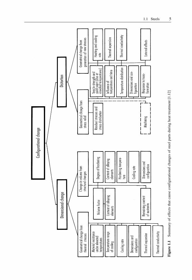
Distortion and dimensional changes often occur as a side effect of heat treatment.Dimensional changes are caused by thermal stresses and changes in volume resultingfrom transformations within the steel. They are unavoidable. Distortion, on the otherhand, is caused by incompetent execution of heat treatment before, during, or after theforming process, or by faulty mold design (sharp corners and edges, large differences incross sections etc.). Deviation from the accurate shape as a consequence of heattreatment is always the sum of distortion and dimensional change. The two cannot bestrictly separated. Figure 1.1 points out the various effects which cause configurationalchanges. Use of steels with a low tendency to dimensional changes reduces such effectsto a minimum [1.11, 1.12].
Prehardened, martensitic hardenable, and through-hardening steels should bepreferred in order to avoid distortion. Pretreated steels do not need any appreciable heattreatment after forming. The required wear resistance of these steel grades is achievedby a chemical process (e.g. chrome plating) or a diffusion process (e.g. nitriding attemperatures between 450 and 600 °C). Because of the low treatment temperature of 400to 500 °C for martensitic steels, only small transformation and thermal stresses occur inthese steels, and the risks generally associated with heat treatment are slight [1.13]. Inthrough-hardening steels, the heat treatment causes a uniform structure throughout thecross section and thus no appreciable stresses occur.
The range of applications for through-hardening steels is limited, however, since thedanger of cracking under bending forces is high, especially in the case of molds withlarge cavities. Demands for molds with a tough core and a wear-resistant, hardenedsurface are best met with case-hardening steels (e.g. for long cores or similar items).
High wear in use is most effectively countered with high surface hardness. The besthardening results and a uniform surface quality can be achieved with steels that are freefrom surface imperfections, are of the highest purity and have a uniform structure.Completely pure steels are the precondition for the impeccably polishable, i.e. flawless,mold surface required for processing clear plastics for optical articles. A high degree ofpurity is obtained only with steels that are refined once or more. Remelting improves themechanical properties, too. These steels have gained special importance in mold makingfor producing cavity inserts.
The maximum abrasive strength is obtained with steels produced by powdermetallurgy (hard-material alloys).
Mold temperature and heat exchange in the mold are determined by the plasticmaterial and the respective molding technique. The thermal effect of the moldtemperature during the processing of the majority of thermoplastics (usually below120 °C) is practically insignificant for the selection of the mold material. There are,however, an increasing number of thermoplastics with melt temperatures up to 400 °Cthat require a constant mold temperature of more than 200 °C during processing. Mold
51.1 Steels
Fig
ure
1.1
Sum
mar
y of
eff
ects
tha
t ca
use
conf
igur
atio
nal
chan
ges
of s
teel
par
ts d
urin
g he
at t
reat
men
t [1
.12]

6 1 Materials for Injection Molds
temperatures for thermosets are also between 150 and 250 °C. At this point, themechanical properties of the mold material are affected. Wear and tendency to distortionincrease, creep to rupture data and fatigue resistance decrease [1.14]. This has to be takeninto account through selecting the most suitable material. A heat-treatment diagram(hardness versus temperature) can indicate the permissible temperature of use if the latteris taken as 30 to 50 °C below the tempering temperature.
Heat exchange between the solidifying molding and the mold has a substantial effecton the cost of a part. This heat exchange is considerably influenced by the thermalconductivity of the mold material which again is affected by its alloying components.Their different structures give rise to varying thermal conductivity. Notch sensitivity canbe countered to a certain degree with case hardening or nitriding because such treatmentcauses compressive stresses in the surface [1.15]. Nevertheless, attention should be paidto avoiding notches during the design and manufacturing stages.
Some plastics release chemically aggressive substances during processing, such ashydrochloric acid, acetic acid or formaldehyde. They attack the mold surface if it is notprotected with a deposit of hard chromium or nickel.
Since such deposits have a tendency to peel off if the molds are improperly designed(e.g., shape, sharp corners) or handled, corrosion resistant steels should be used formaking molds which are employed under such conditions. Then no further precautionsagainst possible corrosion from humidity or coolant are necessary.
The demands listed so far are partially contradictory. Therefore the mold designer andmold maker have to select that steel grade which is best suited for a particular job.
The following steel grades are presently offered for producing cavity inserts:
– case hardening steels,– nitriding steels,– through-hardening steels,– tempered steels for use as supplied,– martensitic-hardening steels,– hard-material alloys,– corrosion-resistant steels,– refined steels.
The most important steels for mold making are shown in Table 1.2, along with theircomposition, heat treatment and application areas. A more detailed characterization ofthese groups of steels is provided below.
1.1.2 Case-Hardening Steels
Case-hardening steels best meet the qualifications for mold making. They are notexpensive, and it should not come as a surprise that their share is about 80% of the totalsteel consumed in mold making [1.16] (This figure includes consumption for base andclamp plates). Unalloyed or low-alloyed steels offer a special advantage. Through casehardening, carburization or cementization (so-called because cementite is formed duringsubsequent hardening), a mold surface as hard as glass is generated and, at the sametime, a tough, ductile core. The hard surface renders the mold wear resistant and thetough core confers resistance to shock and alternate loading [1.17].
There are other criteria favoring the application of case-hardening steels overhighcarbon and through-hardening steels. Easy machining and, if properly produced and
71.1 Steels
treated, very good polishing are especially worth mentioning. In carburization, there isthe possibility of performing local hardening by covering certain areas. However, theextensive heat-treatment procedure required for carburization cannot preventdimensional changes from occurring, with the result that additional outlay is requiredbefore the molds can be used [1.18]. Another advantage over the other steel groups is thelow strength after low-temperature annealing. Case-hardening steels are thereforesuitable for hobbing (see Section 2.3). This process is particularly suitable for smallcavities and multi-cavity molds with a large number of equal cavities.
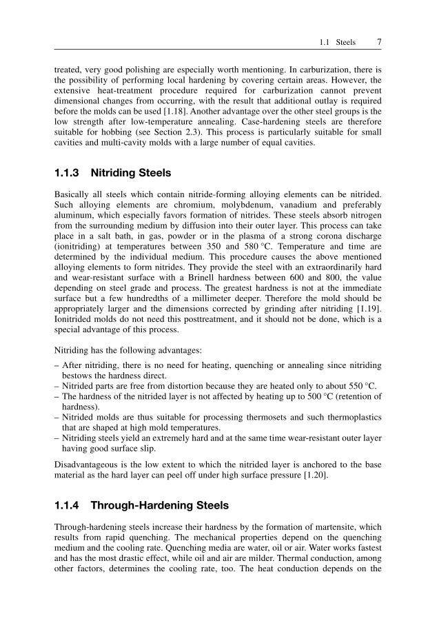
1.1.3 Nitriding Steels
Basically all steels which contain nitride-forming alloying elements can be nitrided.Such alloying elements are chromium, molybdenum, vanadium and preferablyaluminum, which especially favors formation of nitrides. These steels absorb nitrogenfrom the surrounding medium by diffusion into their outer layer. This process can takeplace in a salt bath, in gas, powder or in the plasma of a strong corona discharge(ionitriding) at temperatures between 350 and 580 °C. Temperature and time aredetermined by the individual medium. This procedure causes the above mentionedalloying elements to form nitrides. They provide the steel with an extraordinarily hardand wear-resistant surface with a Brinell hardness between 600 and 800, the valuedepending on steel grade and process. The greatest hardness is not at the immediatesurface but a few hundredths of a millimeter deeper. Therefore the mold should beappropriately larger and the dimensions corrected by grinding after nitriding [1.19].Ionitrided molds do not need this posttreatment, and it should not be done, which is aspecial advantage of this process.
Nitriding has the following advantages:
– After nitriding, there is no need for heating, quenching or annealing since nitridingbestows the hardness direct.
– Nitrided parts are free from distortion because they are heated only to about 550 °C.– The hardness of the nitrided layer is not affected by heating up to 500 °C (retention of
hardness).– Nitrided molds are thus suitable for processing thermosets and such thermoplastics
that are shaped at high mold temperatures.– Nitriding steels yield an extremely hard and at the same time wear-resistant outer layer
having good surface slip.
Disadvantageous is the low extent to which the nitrided layer is anchored to the basematerial as the hard layer can peel off under high surface pressure [1.20].
1.1.4 Through-Hardening Steels
Through-hardening steels increase their hardness by the formation of martensite, whichresults from rapid quenching. The mechanical properties depend on the quenchingmedium and the cooling rate. Quenching media are water, oil or air. Water works fastestand has the most drastic effect, while oil and air are milder. Thermal conduction, amongother factors, determines the cooling rate, too. The heat conduction depends on the

8 1 Materials for Injection Molds
Steel type AISI Composition (%) Thermal Thermal No. conductivity expansion
(W/(m · K)) (10–6 K–1)
Carbon steel 1020 0.18–0.23 C 0.30–0.60 Mn 46.7 11–150.04 P 0.05 S
1030 0.28–0.34 C 0.60–0.90 Mn 46.7 14.90.04 P 0.05 S
1040 0.37–0.44 C 0.60–0.90 Mn 46.70.04 P 0.05 S
1095 0.90–1.03 C 0.30–0.50 Mn 43.3 11–140.04 P 0.05 S
Alloy steel 4130 0.28–0.33 C 0.30–0.60 Mn 46.70.20–0.35 Si 0.80–1.10 Cr0.15–0.25 Mo 0.035 P0.04 S
4140 0.38–0.43 C 0.75–1.00 Mn0.20–0.35 Si 0.80–1.00 Cr0.15–0.25 Mo 0.035 P0.04 S
6150 0.48–0.53 C 0.70–0.90 Mn 60.6 10–120.20–0.35 Si 0.80–1.10 Cr0.15 V 0.035 P 0.04 S
8620 0.18–0.23 C 0.70–0.90 Mn0.20–0.35 Si 0.40–0.70 Ni0.40–0.60 Cr 0.15–0.25 Mo0.035 P 0.04 S 46.7
Tool steelsShock-resisting S1 0.50 C 0.75 Si 1.25 Cr 62.3 11–13steels: 2.50 W 0.20 V
S7 0.50 C 0.70 Mn 0.25 Si 14.93.25 Cr 1.40 Mo
Cold-work steels:– oil hardening O1 0.90 C 1.20 Mn 0.50 Cr
0.50 W 0.20 V– medium alloy, A2 1.00 C 1.00 Mo 5.00 Cr– air hardening A4 0.95 C 2.00 Mn 0.35 Si
2.20 G 1.15 Mo– medium alloy, A6 0.70 C 2.00 Mn 1.00 Cr– air hardening 1.00 Mo– high carbon, D2 1.50 C 1.00 Mo 12.00 Cr– high chromium 1.00 V
Hot-Work steels:– chromium base H13 0.35 C 0.40 Mn 1.00 Si 24.6 12–13
1.40 Mo 5.00 Cr 1.00 V– tungsten base H23 0.30 C 12.00 Cr 12.00 WSpecial purpose steels: L6 0.75 C 0.75 Mn 0.90 Cr– low-alloy 1.75 Ni 0.35 Mo
Mold steels:– low carbon P2 0.07 C 0.20 Mo 2.00 Cr– medium alloy P20 0.35 C 0.80 Mn 0.50 Si 29.0 12.7
0.45 Mo 1.70 CrStainless steel: 420 0.15 C (min.) 1.00 Mn 1.00 Si 23.0 11–12(martensitic) 12.00–14.00 Cr
Table 1.2 Steels for injection molds [1.18, 1.26, 1.28]
Such tables are subject to change from time to time with new steels added or others eliminated,and comprosition of steels is sometimes altered. Current publications (AISI/SAE) should beconsulted if latest information is desired.

91.1 Steels
surface-to-volume ratio of the mold and the alloying elements added to the steel. Ni, Mn,Cr, Si and other elements lower the critical cooling rate and, therefore, permitthroughhardening of larger cross sections [1.17].
The hardening process consists in preheating, heating to prescribed temperature,quenching with formation of a hard martensitic structure and then normalizing toimprove toughness. Because of the low toughness of through-hardening steels, moldswith deep cavities have a higher risk of cracking.
Unlike tempering, normalizing reduces the hardness only slightly. The temperaturesfor normalizing are between 160 and 250 °C. Besides improving toughness, normalizinghas the effect of reducing stresses. (Occasionally this treatment is, therefore, called stressrelieving but it should not be confused with stress-relieving annealing.)
Through-hardening steels exhibit very good dimensional stability when heat-treated.Because of their natural hardening capacity they have high compressive strength and areespecially suitable for molds with shallow cavities where high pressure peaks may beexpected. They can also be recommended in molds for insert molding (with possiblehigh edge pressure) and, due to good wear resistance and high normalizing temperatures,for processing thermosets [1.20, 1.21].
As far as the mechanical properties are concerned, through-hardening steels have ahomogeneous structure. Major postmachining does not remove outer layers havingspecial strength as is the case with case-hardening steels. Since the introduction ofelectrical discharge machining (EDM), the use of through-hardening steels has beensteadily gaining in importance.
1.1.5 Heat-Treated Steels
These steels are tempered by the manufacturer and can therefore be used as suppliedwithout the need for further heat treatment.
After hardening, these steels are submitted to a tempering process. At temperaturesabove 500 °C, the martensite decomposes into carbide and alpha iron. This causes areduction in hardness and strength of these steels and, at the same time, an increase intoughness. Ductility and toughness increase with rising tempering temperatures;hardness and strength, however, decrease.
Through judicious choice of temperature (usually constant) and duration of tempering(1 to 2 hours), it is possible to obtain a certain degree of toughness, the exact valuedepending on the strength. 1200 to 1400 MPa yield strength can be assumed as the upperlimit. Steels of higher strength can no longer be economically machined [1.22].
To improve the machining properties, sulfur (0.06%) is added to the heat-treatedsteels. However, this reduces the scope for electroplating the mold surfaces, such as byhard chroming. Similarly, photo-etchability is severely restricted by the manganesesulfides emitted at the surface.
These disadvantages are compensated by treating the steels in some cases withcalcium as they are being made. The sulfur content can thereby be reduced (< 0.005%;these steels are said to be highly desulfurized) and the machinability and etchabilityimproved simultaneously [1.18, 1.23].
Heat-treated steels are preferably employed for medium-sized and large molds. Theyhave the additional advantage that corrections are more easily accomplished if deemednecessary after a first trial run [1.2, 1.25].

10 1 Materials for Injection Molds
1.1.6 Martensitic Steels
Martensitic steels combine extreme strength and hardness with the advantage of simpleheat treatment. They are supplied in an annealed state. Their structure consists of toughnickel martensite with a strength of 1000–1150 MPa. To an extent depending on theirstrength, their machinability is comparable to that of tempered steel. It takes about 10 to20% more machine time than with mild steels.
After machining, molds are subjected to a simple heat treatment that harbors no risks.They are heated up to temperatures between 480 and 500 °C, kept at this temperature for3 to 5 hours and slowly cooled in still air. No normalizing is done.
Due to the low hardening temperature, no distortion is to be expected. There is onlya slight dimensional change from a shrinkage of 0.05 to 0.1% on all sides. The wearresistance of the mold surface can be improved even further by a diffusion process suchas nitriding. Care should be taken not to exceed 480 to 500 °C when doing this. Thepreceding hardening step can be omitted if diffusion treatment occurs. The extraordinarytoughness of martensitic steel at the high hardness of 530 to 600 Brinell is remarkable[1.2, 1.13, 1.20, 1.25].
The use of martensitic steels is recommended for smaller cavity inserts with complexcontours that exhibit large differences in cross sections and detached thin flanges.
The use of other steel grades for such molds would definitely result in distortion.It should be noted that hardened martensitic steels can be easily welded using materialsof the same kind without the need for preheating.
1.1.7 Hard Mold Alloys
Hard mold alloys are steels produced by a powder-metallurgical process that have a highproportion of small carbides which are uniformly embedded in a steel matrix of differentcomposition, primarily a chromium-molybdenum-carbon matrix with added cobalt andnickel [1.18, 1.26–1.28]. These practically isotropic steels are produced in a diffusionprocess under pressure and temperature from homogeneous alloying powders ofmaximum purity. To an extent depending on the steel grade and manufacturer, thesesteels have a titanium carbide content of 50 vol.%. This high carbide content renders thesteels extremely wear resistant. They are thus particularly suitable for processingwearpromoting compounds (thermosets and reinforced thermoplastics) and for varioustool parts subjected to increased wear, such as nozzles, gate systems, etc.
Hard mold alloys are supplied in a soft-annealed state and may be machined. Afterheat treatment (6–8 hours storage at 480 °C), the hardness increases to 60–62 Rc. Toincrease the hardness further, storage may be combined with a nitriding treatment. Thesurface hardness increases as a result to 72–74 Rc [1.27].
Due to their isotropic structure and low coefficient of thermal expansion, hard moldalloys undergo extremely little distortion during heat treatment.
1.1.8 Corrosion-Resistant Steels
Some polymeric materials release chemically aggressive substances during processingthat attack steel and harm the surface, e.g. by causing rusting. One way of protectingmolds against corrosion is afforded by applying a protective electroplating coat (chrom-

111.1 Steels
nickel plating). Complicated geometries make it difficult, however to apply uniformcoatings, particularly on the corners and edges. It is therefore possible that the shape ofthe moldings will change as a result. In addition, protective electroplating coats tend topeel off very easily. If the molds are likely to be used in a corrosive setting, it is advisableto use corrosion-resistant steel.
The corrosion resistance of such steels is due to their having been alloyed withchromium. Given a chromium content of at least 12%, very dense, strongly adhering,invisible layers of chromium oxide are formed in contact with atmospheric oxygen orother oxygen-providing media. They protect the steel against corrosion. In this case thecrystalline structure is a solid solution of iron and chromium. Adding other alloyingelements to steel, especially carbon, may partially reduce the corrosion resistance.Carbon has the tendency to react with chromium and form ineffective chromium carbide.Only in the hardened state does carbon remain bound to the iron atoms or in solution,thereby allowing the chromium to fully play its anti-corrosive function. Through heattreatment above ca. 400 °C, part of the carbon escapes from the solution and can formchromium carbide. Thus, carbon binds part of the chromium, preventing it fromperforming its protective role. Because of the required mechanical properties, however,carbon cannot be dispensed with mold in stainless steels for mold making [1.28].Therefore hardened chrome steel is always the best choice.
The corrosion resistance also depends on the quality of the mold surface. A roughsurface presents a larger area for attack than a smooth, highly polished one. Chrome steelwith only 13% chromium, for instance, is corrosion resistant only if the surface is highlypolished. In addition, the plastics processor himself should make every effort to protecthis molds from corrosion by cleaning them before storage.
Steels with 17% chromium and martensitic structure have better corrosion resistancebut tend to coarseness and formation of soft ferritic parts in their crystalline structure.Only the hard material alloys (tool steels with the maximum carbide content producedby powder metallurgical processes) are not susceptible to these problems (see alsoSection 1.1.7).
1.1.9 Refined Steels
The cosmetic appearance of a plastic molding depends largely on the mold’s surfacequality. Particular attention to this fact should be paid when selecting a steel for moldinserts that will be employed for molding transparent articles such as lenses etc.
The better the steel can be polished, the higher is the surface quality of the mold. Howwell steels can be polished is determined by their degree of purity. This degree dependson the amount of nonmetallic inclusions in the steel, such as oxides, sulfides and silicates[1.19]. These inclusions, unavoidable in an open-hearth steel, can be eliminated byremelting. In modern practice three methods with self-consuming electrodes are applied:melting in an electric-arc vacuum oven, in an electron beam oven or by electro-slagrefining.
For refining in an electric-arc vacuum oven, a normally produced steel rod as self-consuming electrode is burnt off in a cooled copper die under high vacuum (10–1 or 10–3 Pa).
In an electron beam oven, the rod is melted in an ingot mold by an electron beam.Electro-slag refining has gained greatest importance in recent years. In this process,
the electrode, which is in the form of a completely alloyed block, dips into electricallyconductive liquid slag in a water-cooled mold and is melted [1.29]. The melt dripping

12 1 Materials for Injection Molds
from the electrode passes through the liquid slag and is purified by respectivemetallurgical reactions [1.30, 1.31].
Refined steels have the following advantages over those conventionally produced:
– more homogeneous primary structure and extensive freedom from ingot liquation andinternal defects from solidification,
– less crystal liquation and therefore more homogeneous microstructure,– reduced quantity and size and a more favorable distribution of nonmetallic inclusions,
such as oxides, sulfides and silicates [1.32].
Remelted and refined steels are the purest steels presently on the market. Therefore theycan be very well polished.
1.2 Cast Steel
The production of molds from forged or rolled steel is relatively expensive because ofthe high labor costs for machining and the expenses for the necessary equipment whichis partly special machinery. In addition, there are high material losses from cuttingoperations, which can amount to 30 to 50% for large cavities [1.19]. Besides this, stylistsand consumers demand a molding whose surface quality or texture cannot be producedin a cavity by conventional cutting operations. Solutions can be found in physical orchemical procedures or precision casting.
The most common casting steel grades and casting processes are discussed in detailin Sections 2.1.1–2.1.3. A summary of cast steel alloys is shown in Table 1.3.
1.3 Nonferrous Metallics
The best known nonferrous metals employed in mold making are:
– copper alloys,– zinc alloys,– aluminum alloys,– bismuth-tin alloys.
1.3.1 Copper Alloys
The importance of copper alloys as materials for mold making is based on their highthermal conductivity and ductility, which equalizes stresses from nonuniform heatingquickly and safely. The mechanical properties of pure copper are moderate. Althoughthey can be improved by cold rolling or forming, they generally do not meet the demandson a mold material.
Therefore, copper serves in mold making at best as an auxiliary material, for instance,as components of heat exchangers in molds cast from low melting alloys. Beryllium-copper-cobalt alloys, however, are important materials for mold cavities.

131.3 Nonferrous Metallic Materials
1.3.1.1 Beryllium-Copper Alloys
As with other alloys, the mechanical and thermal properties depend on the chemicalcomposition of the alloy. With increasing beryllium content, the mechanical propertiesimprove while the thermal properties deteriorate. Beryllium-copper alloys with morethan 1.7% beryllium have prevailed in mold making. They have a tensile strength of upto 1200 MPa and can be hardened up to 440 Brinell. Hardening up to 330 to 360 Brinellis generally sufficient for practical purposes. In this range the material is very ductile,has no tendency to fragility at the edges, and is readily polishable [1.39].
Carbon steels AISI 1020 0.18–0.23% C 0.30–0.60% Mn 0.04% P 0.05% Sannealed BH 122, normalized BH 134Welding is readily done by most arc and gas processes. Preheating unnecessary unless parts are very heavy
AISI 1040 0.37–0.44% C 0.60–0.90% Mn 0.04% P 0.05% Snormalized and annealed BH 175normalized and oil quenched BH 225Welding can be done by arc, resistance and gas processes. Todecrease cooling rate and subsequently hardness preheating toabove 150 preferably 260 °C. Final heating to 600–650 °Crestores ductility and relieves stress
Alloy steels AISI 1330 0.28–0.33% C 1.60–1.90% Mn 0.20–0.35% Si0.035% P 0.04% Snormalized BH 187, normalized and tempered BH 160Can be relatively easily welded with mild-steel filler metal
AISI 4130 0.28–0.33% C 0.40–0.60% Mn 0.20–0.35% Si0.80–1.10% Cr 0.15–0.25% Mo 0.035% P 0.04% Sannealed BH 175Welding same as 1330
AISI 4340 0.38–0.43% C 0.60–0.80% Mn 0.20–0.35% Si1.65–2.00% Ni 0.70–0.90% Cr 0.20–0.30% Mo0.035% P 0.04% Snormalized and annealed BH 200quenched and tempered BH 300Welding calls for pre- and postheating and filler metals of thesame mechanical properties as the base metal. Stress relieving isdesirable especially in repair work
AISI 8630 0.28–0.30% C 0.70–0.90% Mn 0.20–0.35% Si0.40–0.70% Ni 0.40–0.60% Cr 0.15–0.25% Monormalized BH 240, annealed BH 175Welding preferably with filler metal of the same chemicalanalysis. No preheating needed for sections up to 0.5 in. butstress relieving after welding
Heat-resistant AISI 501 0.10% C 1.00% Mn 1.00% Si 4.00–4.00% Crsteel 0.40–0.65% Mo
Welding similar to 8630
Table 1.3 Cast steels for injection molds; composition – treatment – properties [1.38]

14 1 Materials for Injection Molds
Tempering, which provides a homogeneous hardness, can be done in a simple oven [1.40].Alloys with a beryllium content below 1.7% are only used for functional components,
such as heat conductors in heat exchangers, because of their diminished strength.Table 1.4 summarizes the technical data of some beryllium-copper alloys.
Molds made of beryllium copper are sufficiently corrosion resistant and can bechrome or nickel plated if needed. Protective coating is mainly done by electroless nickelplating today. It has the advantage of a more even deposit and a hardenability of up to780 Brinell with an appropriate heat treatment at about 400 °C. Besides this, a nickelcoating is less prone to cracking than a hard chrome coating [1.40]. In contrast to caststeel, beryllium-copper alloys are practically insensitive to thermal shock.
Mechanical damage can be repaired by brazing or welding. Beryllium-copper rodswith about 2% beryllium are preferably used for welding with 250 Amps [1.39, 1.40].The molds are appropriately preheated to 300 °C [1.40].
Molds of beryllium copper can be made by machining or casting. Cold-hobbing isonly conditionally suitable for shallow cavities. The alloy can be better formed byhothobbing in a temperature range of 600 to 800 °C followed by solution annealing.
Beryllium-copper alloys are employed as materials for molds or functionalcomponents wherever high heat conductivity is important either for the whole mold orpart of it. The temperature differential between cavity wall and cooling channel isreduced. This results in higher output with the same, or often better, quality with thesame cooling capacity. These alloys also offer an advantage if high demands on surfaceaccuracy have to be met. They are well suited for casting with patterns having astructured surface such as wood, leather or fabric grain.
1.3.2 Zinc and its Alloys
High-grade zinc alloys for casting are used in mold making only for prototype molds ormolds for small production runs because of their inferior mechanical properties. They aremore frequently utilized for blow molding or vacuum forming where molds are notunder high mechanical loads. Zinc alloys, like copper alloys, are characterized by highthermal conductivity of about 100 W/(m · K).
Molds of zinc alloys are mostly cast. The low casting temperature (melting point ca.390 °C, casting temperature 410 to 450 °C) is a special advantage. It allows patterns tobe made of wood, plaster, or even plastics, in addition to steel. Patterns of plaster andplastics can be made especially easily and fast. High-grade zinc alloys can also be castin sand and ceramic molds. Die casting, although possible, is used only rarely.
The excellent behavior of zinc alloys during casting produces smooth and nonporoussurfaces of intricate and structured surfaces [1.39]. Molds, especially plaster molds, mustbe adequately dried before use (plaster for several days at 220 °C), since otherwise aporous and rough cavity surface results from the generation of steam [1.21].
Molds of high-grade zinc alloys can also be made by cold-hobbing. The blank ispreheated to 200 to 250 °C before hobbing. Even deep cavities are produced in one stepwithout intermediate annealing. Hobs with a Brinell hardness of 430 are employed.Vertical motion is sometimes combined with rotation. With such hobs cavity inserts formolding helical gears can be made [1.21].
Another process using high-grade zinc alloys is metal spraying (Section 2.2).Because of low mechanical strength only cavity inserts are made of high-grade zinc
alloys. These inserts are fitted into steel bases, which have to resist the forces from

151.3 Nonferrous Metallic Materials
Designation C 17 200 C 17 300 C17 000 C 17 510 C 17 500
Composition Be Be Be Be Be1.80–2.00% 1.80–2.00%, 1.60–1.79% 0.20–0.60% 0.40–0.75%Co/Ni Co/Ni Co/Ni Ni Co0.20% min. 0.20% min., 0.20% min., 1.40–2.20% 2.40–2.70%Co/Ni/Fe Co/Ni/Fe Co/Ni/Fe Cu balance Cu balance0.6% max., 0.6% max., 0.6% max.,Cu balance Pb Cu balance
0.20–0.6%,Cu balance
Density kg/m3 8250 8415 8610 8775Therm. conductivity
W/(m · K) 130 130 260 260
Therm. expansion10–6 K–1 17.5 17.5 17.6 18
Specifie heat capacityJ/(kg · K) 420 420 420 420
Electric resistivity10–8W · m 7.7 7.7 3.8 3.8
Modulus of elasticity GPa 131 128 138 138
Tensile strength [MPa] I 415–585 I 415–585 I 240–380II 620–895 II 620–895 II 450–550III 1140–1310 III 1035–1310 III 690–830IV 1275–1480 IV 1170–1450 IV 760–900
Yield strength [MPa] I 140–415 I 140–205 I 140–310II 515–725 II 515–725 II 340–515III 1000–1200 III 860–1070 III 550–690IV 1140–1380 IV 930–1140 IV 690–830
Elongation [%] I 35–60 I 35–60 I 20–35II 10–20 II 10–20 II 10–15III 3–10 III 4–10 III 10–25IV 2–5 IV 2–5 IV 10–20
Rockwell hardness I B45–80 I B45–85 I B25–50II B88–103 II B91–103 II B60–75III C36–41 III C32–39 III B92–100IV C39–44 IV C35–41 IV B95–102
Table 1.4 Technical data of beryllium-copper [1.41]
Notes: I: Solution heat treatedII: Cold drawnIII: Solution heat treated and age hardenedIV: Cold drawn and age hardened

16 1 Materials for Injection Molds
clamping and injection pressure during the molding process. The most commonhighgrade zinc alloys, known under their trade names Zamak or Kirksite, aresummarized in Table 1.5.
1.3.3 Aluminum Alloys
For a long time, aluminum was not used to any major extent for making injection molds.However, extensive improvements in properties, particularly mechanical properties,have led to this material being used more and more often in recent times. The mainproperties in favor of using aluminum for mold making are:
– low density,– good machinability,– high thermal conductivity, and– corrosion resistance.
Aluminum alloys are available as casting and forging alloys. The casting alloys are notof much significance. Casting is difficult. Perfect molds presuppose correct choice ofalloy, the appropriate melting and casting technique and a mold design amenable tocasting. It is therefore advisable to collaborate with the manufacturer at the designstage.
More important for mold making are the forging alloys which, in the form ofheathardening, high-strength aluminum-zinc-magnesium-copper alloys, have alreadyshown their mettle in aircraft construction. These are now available commercially in theform of complete mold structures as well as plates that have been machined on all sidesand as blanks [1.44]. The chemical composition and physical properties of a typicalaluminum alloy used in mold making are shown in Table 1.6.
Aluminum molds weigh less than steel molds due to their specific weights (between2.7 and 2.85 g/cm3, depending on alloying additives). Unfortunately this “positivecharacteristic” is not fully recognized because the individual plates, which arecomponents of a mold, have to be about 40% thicker than steel plates because of theirlower mechanical strength (modulus of elasticity is only roughly 30% that of steel; Table1.6). In spite of this, aluminum molds weigh about 50% less than steel molds. This is aconsiderable advantage during mold making and assembly as well as later on duringsetup in the molding shop. With smaller molds, it is frequently possible to do withoutexpensive lifting devices such as cranes and lift trucks.
Additional advantages result from good machinability, which can allow cuttingspeeds five times as fast as those for steel [1.44]. This holds particularly true if therecommendations of the producer are taken into account and those tools are used whichare especially suited for aluminum. Distortion from machining is not to be expectedbecause aluminum has very little residual stresses due to special heat treatment duringproduction (the wrought products are hot-rolled, then heat-treated and stretched untilstress-free). Aluminum can be worked with cutting tools as well as shaped by means ofEDM.
Electrode material made of electrolytic copper or copper containing alloys areprimarily used for this procedure. Here, too, the high eroding speed (6 to 8 times that ofsteel) is economically significant. Cut or eroded surfaces can be polished with standardmachines and wheels and made wear resistant by chrome plating or anodizing. Servicelives of up to 200,000 shots per mold have been achieved with aluminum molds, the

171.3 Nonferrous Metallic Materials
Des
igna
tion
Den
sity
Mel
ting
Shr
inka
geT
herm
al
Tens
ile
Elo
ngat
ion
Bri
nell
C
ompr
essi
ve
She
ar(k
g/m
3 )po
int
%ex
pans
ion
stre
ngth
(% i
n 50
mm
)ha
rdne
ssst
reng
th
stre
ngth
(°C
)(1
0–6/K
)(M
Pa)
BH
(MP
a)(M
Pa)
Zam
ak67
0039
01.
127
220–
240
1–2
1000
600–
700
300
Kir
ksit
e A
6700
380
0.7–
1.2
2722
63
1000
420–
527
246
Kay
em67
0038
01.
128
236
1.25
1090
793
–K
ayem
266
0035
81.
1–
149
Ver
y lo
w14
50–1
500
685
–
Tab
le 1
.5H
igh-
grad
e zi
nc a
lloy
s fo
r in
ject
ion
mol
ds [
1.42
, 1.4
3]
Che
mic
al c
ompo
siti
on
A.A
.C
ompo
siti
on (
wt.
-%)
No.
Cu
Cs
Fe
Mg
Mn
Si
Ti
Zn
Oth
ers
3.43
651.
2–2.
00.
18–0
.28
0.5
2.1–
2.9
0.3
0.4
0.2
5.1–
6.1
Ti
+ Z
r =
0.2
5
Phy
sica
l pro
pert
ies
A.A
.D
ensi
tyY
ield
str
engt
hU
ltim
ate
tens
ile
Mod
ulus
of
Coe
ffic
ient
of
The
rmal
N
o.st
reng
thel
asti
city
ther
mal
exp
ansi
onco
nduc
tivi
ty
kg/d
m3
N/m
m2
N/m
m2
MP
aW
/(m
°C)
W/(
K·m
)
3.43
652.
8241
0–53
048
0–61
072
000
23.7
153
(0–1
00°C
)
Tab
le 1
.6C
hem
ical
com
posi
tion
and
phy
sica
l pr
oper
ties
of
a ty
pica
l he
at-h
arde
ning
alu
min
um f
orgi
ng a
lloy
use
d fo
r m
old
mak
ing
[1.4
4, 1
.45,
1.4
7]

number depending on the application [1.48, 1.49]. Surface treatment will be discussedlater.
The thermal conductivity of the materials used for the molds is critical to injectionmolding. When aluminum alloys are used, it ensures good, rapid heat distribution anddissipation. This shortens cycle times and may lead to enhanced quality of moldings.
In the presence of atmospheric oxygen, a dense, strongly adhering oxide layer about0.001 µm thick forms on the surface of the aluminum [1.44, 1.46]. This layer protects theunderlying materials, particularly in dry environments, against atmospheric attack. If itis destroyed or removed during machining, it re-forms anew spontaneously. It isdamaged by acids formed from salts and gases in contact with moisture (water ofcondensation). If this kind of stress is expected during operation, surface treatment isadvisable. Good results in this connection have been produced by
– chrome plating,– nickel plating,– anodizing, and– PVD coating.
Surface treatment enhances not only corrosion resistance but also wear and abrasionresistance and sometimes facilitates demolding. Layer thicknesses and hardnessesobtained with the aforementioned coating methods are summarized in Table 1.7.
Due to the positive aspects for mold making described above, mold plates already milledand surface-ground to finished dimensions, with the corresponding bores for guidesystems right through to complete mold structures, are now commercially available.
Designs combining aluminum with steel have yielded good results. This constructionhas the advantage of allowing the more resistant steels to be used for areas subject tohigh wear and abrasion. It therefore combines the advantages of both materials.
The service life of aluminum molds depends on the plastic to be processed (reinforcedor unreinforced), its processing conditions (injection pressure, temperature) and thegeometry of the molding. The literature contains reports of molds that have produced15,000–200,000 moldings. Aluminum is of little or no suitability for processingthermosets on account of the high processing temperatures and the associated thermalstress [1.45, 1.49].
1.3.4 Bismuth-Tin Alloys
Bismuth-tin alloys are marketed under the trade name Cerro alloys. They are relativelysoft, heavy metals, which generally react to shock in a brittle manner but exhibit plasticityunder constant loading. The strength of these alloys increases with aging [1.51].
18 1 Materials for Injection Molds
Process Layer thickness Hardness
Chrome plating 20–200 µm 900–1100 HVNickel plating 35–50 µm 500–600 HVAnodizing 30–60 µm 350–450 HVPVD coating 5–10 µm
Table 1.7 Coating processes for aluminum and properties obtained [1.45, 1.47]

191.4 Materials for Electrolytic Deposition
Bismuth-tin alloys are compositions of metals with low melting points (between 40 and170 °C depending on composition). They are suitable for normal casting as well as for dieor vacuum casting. They can also be used with a special spray gun. Those alloys whichdo not change their volume during solidification are particularly suited for making molds.
Because of their moderate mechanical properties, bismuth-tin alloys are primarilyused for prototype molds in injection molding. More common is their use for blowmolds, molds for hot forming and for high-precision matrices in electrolytic depositing.Besides this, they are used as a material for fusible cores, which will be discussed inmore detail later on (Section 2.10). Table 1.8 shows the physical and chemical Propertiesof some Cerro alloys.
1.4 Materials for Electrolytic Deposition
Electrolytic deposition of metals has two applications in mold making. A distinction ismade between “decorative” plating and electrolytic forming. The techniques are similarbut their end products and their intended use are very much different. In plating, a thinlayer, usually about 25 µm thick, is deposited. This layer is intended to protect the metalunderneath from corrosion, to facilitate demolding, and to reduce forming of depositsand facilitate the cleaning of molds.
To do this, the electrolytic deposit must adhere well to the substrate.In electrolytic forming, a considerably thicker layer is deposited on a pattern that has
the contours and dimensions of the later cavity insert. The thickness of the deposit isarbitrary and limited only by production time. After the desired thickness is obtained andfurther work in the form of adding a backing is completed, the structure should detacheasily from the pattern.
There are a number of materials that can be electrolytically deposited. The mostimportant ones are nickel and cobalt-nickel alloys. Nickel is the most frequently -employed metal for electrolytic forming because of its strength, toughness, and corrosionresistance. Besides this, the process is simple and easily controlled. Hardness, strength,
Designation (registered trademark) Cerrotru Cerrocast
Density kg/dm3 8.64 8.16
Melting point or range °C 138 138–170
Specific heat kJ/kg 1.88 1.97
Thermal expansion 10–6 15 15
Thermal conductivity W/(K · m) 21 38
Brinell hardness BHN 22 22
Ultimate tensile strength MPa 56 56
Elongation (slow loading) % 200 200
Max. constant load MPa 3.5 3.5
Composition% Bi 58 40% Sn 42 60
Table 1.8 Bismuth-tin alloys (Cerro® alloys) for injection molds [1.52]

ductility, and residual stresses can be varied within a broad range by selecting certainelectrolytic solutions and process conditions [1.53, 1.54].
Even the hardest forms of electrolytically deposited copper and iron are too soft forcavity walls. Copper is primarily used for backing an already formed nickel shell. Therate at which copper can be deposited is a very desirable feature of this procedure.
By contrast, electrolytically deposited chromium is so hard that postoperations suchas drilling holes for ejector pins are impractical. In addition chromium exhibits highresidual stresses, which can easily lead to cracks in the chrome layer. Thereforechromium is used only for protective coatings in mold making.
1.5 Surface Treatment of Steels for Injection Molds
1.5.1 General Information
As already explained in Section 1.1, materials for mold making have to exhibitdistinctive properties. Frequently, a compromise becomes necessary because theproperties of steels depend largely on their chemical composition and the alloyingcomponents affect each other.
Therefore it is reasonable that steel producers and users, together with plasticsprocessors, keep looking for suitable processes to improve the quality and particularlythe service life of injection molds. This can be done by numerous surface treatments. Thegoal of all these processes is to improve
– surface quality,– fatigue and wear resistance,– corrosion resistance,– sliding ability, and – to reduce the tendency to form material residues and deposits in the mold.
The surface properties of components of injection molds can be considerably modifiedby suitable machining, controlled heat treatment or a change in the alloying elements inthe surface layers, by diffusion or build-up. Special demands can thus be met.
Before the details of some selected procedures are discussed below, it must be pointedout that the application of the various processes calls for specialist knowledge and, insome cases, considerable technical resources. Therefore such work is ordinarily done byspecialists. Steel producers also provide advice in this respect.
20 1 Materials for Injection Molds
Hardness 4500–5400 MPaTensile strength 360–1510 MPaTyp. strength for molds 1400 MPaYield strength 230–640 MPaTyp. strength for molds 460 MPaElongation 2–37%Typ. elongation for molds 10%Temperature resistance max. 300 °CCorrosion and wear resistantFine, ductile grain
Table 1.9 Characteristics of electro-deposited nickel [1.53, 1.55]

211.5 Surface Treatment of Steels for Injection Molds
Currently, the most common surface treatments for mold steels are shown in Figure 1.2.Some are presented in more detail below.
1.5.2 Heat Treatment of Steels
In traditional heat-treatment processes changes in the crystalline structure are caused bysimple heating and cooling. This confers distinct properties on the steel. To this end, thesteel producers provide special heat-treatment information showing the feasibility oftreatments and the resulting properties. Such “simple” treatments do not require – aslong as small dimensions are considered – a great amount of technique. They onlyassume a theoretical understanding of the reactions occurring during heat treatment.Annealing, hardening and tempering are considered “simple” treatments.
1.5.3 Thermochemical Treatment Methods
Unlike their thermal counterparts, thermochemical methods utilize chemical elementsthat diffuse from a gaseous, liquid or solid state into the material surface to produce ahard, wear-resistant layer [1.56]. A distinction is drawn between
– carburizing,– nitriding, and– boriding.
1.5.3.1 Carburizing
In carburizing, the carbon content of layers close to the surface of steel, having a lowcarbon content of ordinarily less than 0.25%, and therefore not soluble is increased to as
Figure 1.2 Techniques of surfacetreatment [1.56, 1.57]

much as 0.9% at temperatures between 850 and 980 °C. If quenching is doneimmediately from the carburizing temperature, this process is called direct hardening[1.58]. Carburizing produces a hard surface, which is supported by a soft, tough interiorcore [1.58].
After hardening the steel is tempered. The tempering temperature is determined bylater application or temperature at which the mold is used [1.56] and determines thehardness of the surface. Tempering at temperatures between 100 and 300 °C yields ahardness of 600 to 700 Brinell.
1.5.3.2 Nitriding
Nitriding (see also Section 1.1.3) can be done in a salt bath, in gas, or powder. Themedium determines the temperature and duration of the process. The aim of all processesis to saturate the outer layer of the workpiece by diffusion of nitrogen so as to increasehardness, wear resistance or corrosion resistance.
In nitriding in a bath, the molds are preheated to 400 °C. The nitriding itself is doneat 580 °C. The nitriding time depends on the desired depth of nitriding, but two hours aregenerally sufficient. A special form of nitriding in a bath is the Tenifer treatment, whichis characterized by an aerated nitriding bath of special composition. The required surfacehardness for injection molds is likewise achieved after two hours at a temperature of570 °C [1.59].
Much longer nitriding times are necessary for gas nitriding. The desired surfacehardness takes at least 15 to 30 hours treatment, the exact time depending on the steelgrade. The treatment is performed at temperatures between 500 and 550 °C. It is possibleto selectively nitride certain areas by partially covering the surface with a coating ofcopper or nickel or with a special paste [1.59].
When nitro-carburizing in gas, a reaction component that provides carbon is used inaddition to ammonia. This enriches the connecting zone with carbon. Applicablecomponents are endogas, exogas or combinations thereof as well as natural gas or liquidsthat contain carbon dioxide. The treatment temperatures are about 570 °C, and the timeis 2 to 6 hours.
Activator content, nitriding time and temperature determine the quality of the resultsof powder nitriding for a particular steel grade. It is carried out at temperatures between450 and 570 °C [1.59].
Ionitriding is nitriding in the plasma of a high-amperage corona discharge. It causesnitrogen to be deposited on the mold surface. The hardening depth can range from a fewmicrometers to 1 mm. The greatest hardness is achieved here immediately at the surface,reaching 800 Brinell for some steel grades. Posttreatment of the surface is, therefore,unnecessary. The treatment is done in the temperature range between 350 and 580 °C.Treatment times start at a few minutes and are practically unlimited (20 min to 36 h) [1.60].
Distortion of molds through nitriding or ionitriding does not normally occur. Afterheat treatment, molds are obtained which are tough and free of stresses, have highsurface hardness and improved corrosion resistance.
Nitriding steels are annealed before delivery and can be machined without difficulties.
1.5.3.3 Boriding
In boriding, layers close to the surface are enriched with boron. The result is a very thinbut extremely hard (1800 to 2100 HV 0.025 [1.56]) and wear-resistant layer of iron
22 1 Materials for Injection Molds

231.5 Surface Treatment of Steels for Injection Molds
boride, which is interlocked with the base metal. Boriding can be effected in a solidcompound, through treatment in gas or in borax-based melts, both with and withoutelectrolyte.
Boriding is carried out in a temperature range of 800 to 1050 °C. The usual durationis between 15 minutes and 30 hours. Treatment time, temperature and base materialdetermine the thickness of the layer. Thicknesses of up to 600 µm can be achieved.Partial boriding is feasible.
After boriding, workpieces can be heat-treated to confer a higher “load capacity” on thebase material. The use of a heat-treated steel is a precondition for this. The temperaturedepends on the base material. This treatment should be limited to workpieces with amedium layer of boride (100 to 120 µm). Thicker layers are liable to crack [1.61].
Borided surfaces usually have a dull-gray appearance, and build-up of the boride layeron the surface is possible, the extent depending on the processing conditions. Therefore,a finishing operation in the form of grinding, polishing, lapping or honing is oftennecessary.
1.5.4 Electrochemical Treatments
During processing, some polymeric materials release chemically aggressive substances,mostly hydrochloric or acetic acid. In such cases, the molds are frequently protected byelectrolytic plating with chromium or nickel.
Not only is corrosion resistance enhanced, but also the antifriction properties and, inthe case of chromium, the wear resistance as well.
This plating is permanently effective only if the thickness of the deposit is uniformand sharp edges in the mold are avoided. Nonuniform thickness and sharp edges causestresses in the protective layer, which can lead to peeling off under loads. The risk of anonuniform deposit is particularly great in molds with intricate contours (undercuts etc.).Plated thin flanges subject to bending stresses are very susceptible to cracking.
Before protective plating by electrolytic depositing can be performed, the molds haveto be finished accordingly. Build-up and surface quality of the deposit depend on thequality of the base material. Ground, or even better, polished and compacted surfacesgive the best results.
1.5.4.1 Chrome Plating
The thickness of electrolytically deposited layers of chromium depends on the currentdensity and the temperature of the electrolyte. Their hardness also depends on thetemperature of the heat treatment after plating. Common thicknesses lie between 5 and200 µm, in special cases between 0.5 and 1 mm [1.56]. A surface hardness of 900 HV0.2 is obtained. Because the chrome layer is deposited electrolytically, it builds up inlumps and needs to be reground to the requirements imposed on the quality of the coatedworkpiece.
1.5.4.2 Nickel Plating
A distinction is drawn between electrolytic and chemical nickel plating. The propertiesof the deposits also depend on the processing parameters. Nickel deposits are relativelysoft and therefore not wear resistant.
1.5.4.3 NYE-CARD Process
In order to remedy this disadvantage, procedures have been developed, such as the NYE-CARD process, with which 20 to 70% by volume silicon particles of 25 to 75 µm areincorporated into a nickel-phosphorus layer. The nickel phosphorides contain 7 to 10%phosphorus.
The temperatures to which the material to be coated is exposed are less than 100 °Cduring the process. If subsequent heat treatment to improve adhesion is intended, thetemperature should be about 315 °C. Besides steel, materials such as aluminum orcopper alloys can be coated. It makes sense, however, to employ hardened base materialsdue to of the low thickness of the deposit, and to bring the surface quality of the base upto the required standard.
1.5.4.4 Hard Alloy Coating
Hard alloy coatings are electrolytically deposited protective layers of either tungsten-chromium (Hardalloy W) or vanadium-cobalt (Hardalloy TD). They are applied to asurface that has previously been smoothed and compacted by an ion beam [1.62].
1.5.5 Coating at Reduced Pressure
Common coating techniques based on the principle of deposition from the gas phase arechemical vapor deposition (CVD) and physical vapor deposition (PVD) and theirrespective variants. Both techniques have specific advantages and disadvantages.Because CVD requires high temperatures above the retention of hardness for tool steels,steel materials require subsequent heat treatment. However, this may lead to imprecisedimensions and shapes due to distortion. PVD techniques do not require subsequent heattreatment. However, CVD layers generally yield higher adhesive strength and depth ofpenetration into deep, narrow openings.
1.5.5.1 CVD Process
The CVD process (chemical vapor deposition) is based on the deposition of solids froma gaseous phase by a chemical reaction at temperatures above 800 °C [1.56]. It is shownschematically in Figure 1.3.
In a CVD process, carbides, metals, nitrides, borides, silicides or oxides can bedeposited on the heated surface of molds at temperatures between 800 and 1100 °C.Depending on location and mold type, layers having a thickness of 6 to 30 µm and astrength of up to 4000 MPa may be deposited, e.g. a coating of titanium carbide with athickness of 10 µm. The deposits faithfully copy the surface of the mold, that is, tracesfrom machining of the surface such as scratches and grooves are not hidden by a CVDprocess. Therefore the mold surface must already have the same quality before coatingthat is expected from the finished tool [1.64].
The high temperatures needed for this process cause the base material to loosehardness and strength. This disadvantage must be compensated by another heat treatmentand associated hardening of the base material. Appropriate steel grades should be used.
Because every heat treatment involves risks such as distortion, efforts are being madeto lower the process temperatures with a view to improving the technique. Temperaturesof 700 °C and lower are being discussed [1.65].
24 1 Materials for Injection Molds

251.5 Surface Treatment of Steels for Injection Molds
1.5.5.2 PVD Process
The term PVD (physical vapor deposition) summarizes all those coating techniques bywhich metals, their alloys and their chemical compounds such as oxides, nitrides, andcarbides can be deposited in a vacuum under the simultaneous effects of thermal andkinetic energy through particle bombardment [1.56]. The process is shown schematicallyin Figure 1.4.PVD techniques include
– deposition through evaporation in high vacuum,– ion plating,– sputtering [1.56].
In contrast to the CVD process, the coating of molds by this physical procedure occursat temperatures between 500 and 550 °C. This temperature is in many cases below thetempering temperature of the base material and so further heat treatment (with theassociated risk of distortion) after coating does not become necessary. This process issuitable for all tool steels [1.64].
For the PVD technique, the quality and cleanliness (freedom from rust and grease) ofthe mold surface before coating are also crucial to the bond and surface quality aftercoating.
A variant of PVD, namely PVD arc coating, makes it possible to deposit virtually anycoating material in monolayer and multilayer systems. The coating materials aregenerally chosen on the basis of attainable hardness, coefficient of friction, corrosionresistance and cost. Candidate coating materials or systems include TiN, TiC, TiCN,TiAlN, CrN and CrAlN [1.66, 1.67]. The thinnest hard layers are obtained by ionimplantation, e.g. of nitrogen or carbon [1.68].
PVD coatings have the advantage of being independent of the surface contour for allpractical purposes. They do not affect either the fineness of shape or the dimensional
Figure 1.3 Equipment for depositing titanium carbide (schematic) [1.56]

accuracy. Changes in dimensions are of the order of less than 5 µm and roughness valuesof less than 0.5 µm are attainable [1.37].
So far, titanium nitride (TiN) layers have frequently been used in practice. Titaniumis vaporized in vacuum at temperatures of 550 °C, and together with the nitrogen present,forms a golden wear-resistant deposit up to 5 µm thick on the metal surface [1.36].
The use of PVD layers greatly reduces deposit formation and makes it possible toperform less risky cleaning of the surface.
The use of PVD layers can in some cases considerably extend the service life of themolds (by as much as 20 times). Greatly extended service lives have been demonstratedin molds exposed to corrosive attack, e.g. from the processing of flame-retardentpolyamide or acetal [1.57]. A further major advantage is a lowering of release forces.
1.6 Laser Surface Treatment
Laser surface treatment methods rank among the special finishing procedures. Asidefrom its widespread use for cutting and welding, laser surface treatment is finding moreand more widespread application in industrial practice. Laser surface treatment methodscan be divided into two groups, namely thermal and thermochemical. Laser treatmenttherefore presents an alternative to conventional hardening techniques for increasing theservice life of molds with high component costs.
Thermal variants include laser hardening and laser remelting while thermochemicalmethods include laser alloying, laser dispersing and laser coating. With thethermochemical methods, the material properties are affected not only by the heattreatment but also by the addition of extra materials. The outer layer properties areimproved in respect of the mechanical, tribological, thermochemical and chemical wearresistance of the surface [1.35].
Laser sources nowadays are industrial carbon dioxide lasers rated between 1 and25 kW and Nd:YAG lasers rated at 0.5 to 3 kW. The beam is focused on the surface ofthe workpiece, which becomes heated by absorption. The extent of absorption orreflection depends on the wavelength, the material’s properties and the texture of theworkpiece. Heat incorporation also depends on the intensity of the beam and theexposure time. The exposure time is derived from the rate at which the beam is moved
26 1 Materials for Injection Molds
Figure 1.4 Basics of the PVDtechnique [1.56]
271.6 Laser Surface Treatment
across the surface of the workpiece. Processing usually occurs in adjacent tracks thatmay or may not overlap. It is thus possible to perform large-scale and partial surfacecoating [1.35].
1.6.1 Laser Hardening and Re-Melting
All steel and cast-iron materials with a carbon content exceeding 3% can be laserhardened since they harden martensitically. In laser hardening, the workpiece is heatedto temperatures above the austenitizing temperature; at the surface, heating is due toabsorption of the infrared laser beam and down to a certain depth in the lower zones, dueto heat conduction. This heating process occurs so quickly that the cooling which occursimmediately afterwards creates an extremely steep temperature gradient between theworkpiece surface and the rest of the workpiece. As the laser beam is moved on, theabsorbed quantity of heat is dissipated so quickly inside the workpiece that the criticalcooling rate for martensite formation is exceeded (self-quenching) [1.34].
Laser hardening is a partial hardening process in which the focused beam is guidedback and forth across the area to be hardened. The advantage of this is that selectivehardening can be performed at points where increased wear is expected. As a result,hardening can be performed with very little distortion, zones of partial hardening can bereproducibly created and the workpiece suffers only minor thermal stress. However, thedisadvantage is that large areas have to be hardened in several steps.
Laser re-melting is primarily used for cast materials. The heating and subsequent -selfquenching generate supersaturated solutions, metastable phases and amorphousstructures. Re-melting generates homogeneous, extremely fine-grained structures in theouter layer of the component. These structures are notable for their high strength and, atthe same time, high toughness [1.35].
1.6.2 Laser Alloying, Dispersing, and Coating
Laser alloying is used for completely dissolving additional materials into the basematerial. Convection and diffusion processes in the melting bath lead to homogeneousmixing of the base and additional materials. The high cooling rates ensure that theadditives stay in solution even after cooling. The additive elements and compoundsprimarily increase the wear and corrosion resistance.
By contrast, laser dispersing does not dissolve the additive but rather keeps it finelydispersed in the base structure. Standard high-melting or dissolving-resistant additivesfor laser alloying are SiC, TaC, TiC, VC and WC.
Finally, the aim of laser coating is not to cause any mingling of the base and additivematerials. A homogeneous, strongly adhering layer is generated on the substratematerial. The additive material is completely melted on top and the base structure is onlymelted in the narrow edge zone to create a metallurgical bond. The most commonadditive materials are usually low-melting Ni or Co alloys.

1.7 Electron Beam Hardening
In principle, electron beams may be used instead of laser beams. Consequently, electronbeam hardening works on the same principle as laser hardening. Bombardment by theelectron beam causes rapid heating up and subsequent self-quenching of the outer layerof the workpiece. Since an electron beam is extremely diffuse under ambient conditionsand the necessary intensity cannot be attained, processing can only be carried out inhigh-vacuum chambers. This restriction increases the processing time because a highvacuum has to be produced after the vacuum chamber has been set up. In addition, thecramped conditions of the electron beam equipment restricts the size of the componentsthat can be processed. For these reasons, this process has so far found little industrial use.
1.8 Lamcoat Coating
The Lamcoat process was developed in the USA for smooth, sliding surfaces. In it, a softlayer based on tungsten disulfide is applied mechanically to the mold surface at roomtemperature. To this end, the mold is first thoroughly cleaned in an alcoholic ultrasonicdegreasing bath by means of special high-pressure micro-sprays (no material ablationoccurs). Then the tungsten disulfide is applied manually in a spray booth with the aid ofdry, purified compressed air at high pressure. The coating material does not accumulateon the surface, however, but penetrates extensively into it to form molecular bonds withthe base material. Excess material does not material. As a result, a very thin layermeasuring 0.5–1.5 µm is formed that cannot be made any thicker.
Studies in the USA have shown that a Lamcoat coating reduces friction by up to 70%.This leads to lower injection pressures and increases flow paths by up to 10%. Furtherpositive results are shorter cycle times and a 30–70% increase in mold service life [1.33].This coating technology is currently offered by two companies in Germany.
References[1.1] Becker, H. J.: Herstellung und Wärmebehandlung von Werkzeugen für die Kunst-
stoffverarbeitung. VDI-Z, 114 (1972), 7, pp. 527–532.[1.2] Krumpholz, R.; Meilgen, R.: Zweckmäßige Stahlauswahl beim Verarbeiten von
Kunststoffen. Kunststoffe, 63 (1973), 5, pp. 286–291.[1.3] Kuhlmann, E.: Die Werkstoffe der metallverarbeitenden Berufe. Girardet, Essen, 1954.[1.4] Fachkunde Metall. 50th Ed., Verlag Europe-Lehrmittel Nourney, Vollmer GmbH & Co.,
Haan Gruiten, 1990.[1.5] Werkstoffkunde für Praktiker. 3rd Ed., Verlag Europe-Lehrmittel Nourney, Vollmer
GmbH & Co., Haan Gruiten, 1989.[1.6] Werkstofftechnik für Metallberufe. Verlag Europe-Lehrmittel Nourney, Vollmer GmbH
& Co., Haan Gruiten.[1.7] Das ist Edelstahl. Thyssen Edelstahl Werke AG. Publication, 1980, 2, Krefeld.[1.8] Werkstoff + Werkzeug. Thyssen Edelstahl Werke AG. Publication, 1984, 3, Krefeld.[1.9] König, W.: Neuartige Bearbeitungsverfahren. Lecture, Production techniques, 11, Tech.
University Aachen, Laboratory for Machine Tools and Plant Management.[1.10] Auswahl und Wärmebehandlung von Stahl für Kunststoff-Formen. Arburg heute, 5
(1974), 7, pp. 16–18.[1.11] Dember, G.: Stähle zum Herstellen von Werkzeugen für die Kunststoffverarbeitung,
Kunststoff-Formenbau, Werkstoffe und Verarbeitungsverfahren. VDI-Verlag, Düssel-dorf, 1976.
28 1 Materials for Injection Molds

29References
[1.12] Maßänderungsarme Stähle. Company brochure, Boehler.[1.13] Becker, H. J.: Werkzeugstähle für die Kunststoffverarbeitung im Preß- und Spritzgieß-
verfahren. VDI-Z, 113 (1971), 5, pp. 385–390.[1.14] Catic, I.: Kriterien zur Auswahl der Formnestwerkstoffe. Plastverarbeiter, 26 (1975), 11,
pp. 633–637.[1.15] Werkstoffe für den Formenbau. Technical information, 4.6, BASF, Ludwigshafen/Rh.,
1969.[1.16] Treml, F.: Stähle für die Kunststoffverarbeitung. Paper given at the IKV Aachen,
November 15, 1969.[1.17] Malmberg, W.: Glühen, Härten und Vergüten des Stahls. Springer Verlag, Berlin,
Göttingen, Heidelberg, 1961.[1.18] Mennig, G.: Mold Making Handbook, 2nd ed., Carl Hanser Verlag, Munich, 1998.[1.19] Stoeckhert, K.: Werkzeugbau für die Kunststoffverarbeitung. 3rd Ed., Carl Hanser
Verlag, Munich, Vienna, 1979.[1.20] Weckener, H. D.; Häpken, H.; Dörlam, H.: Werkzeugstähle für die Kunststoff-
verarbeitung. Stahlwerke Südwestfalen AG. Information, 15/75, Hüttental-Geisweid,1975, pp. 31–40.
[1.21] Spritzgießen von Thermoplasten. Company brochure, Farbwerke Hoechst AG.,Frankfurt, 1971.
[1.22] Illgner, K. H.: Gesichtspunkte zur Auswahl von Vergütungs- und Einsatzstählen.Metalloberfläche, 22 (1968), 11, pp. 321–330.
[1.23] Bauer, M.: Kunstofformenstählen – Moderne Werkzeugstähle. Paper presented at the 8thTechnical Conference on Plastic, Würzburg, September 24–25, 1997.
[1.24] Auswahl und Wärmebehandlung von Stahl für Kunststoff-Formen, Arburg heute, 5(1974), 8, pp. 23–25.
[1.25] Auswahl und Wärmebehandlung von Stahl für Kunststoff-Formen, Arburg heute, 5(1974), 7, pp. 16–18.
[1.26] Dittrich, A.; Kortmann, W.: Werkstoffauswahl und Obernächenbearbeitung vonKunststoffstählen. Thyssen Edelst. Technical Report, 7 (1981), 2, pp. 190–192.
[1.27] Frehn, F.: Höchst-Carbidhaltige. Werkzeugstähle für die Kunststoff-Verarbeitung.Kunststoffe, 66 (1976), 4, pp. 220–226.
[1.28] Boehler Company. Publication, Düsseldorf, 1997.[1.29] Becker, H. J.; Haberling, E.; Rascher, K.: Herstellung von Werkzeugstählen durch das
Electro-Schlacke-Umschmelz-(ESU)-Verfahren. Thyssen Edelst. Technical Report, 15(1989), 2, pp. 138–146.
[1.30] Weckener, H. D.; Dörlatu, H.: Neuere Entwicklungen auf dem Gebiet der Werkzeug-stähle für die Kunststoffverarbeitung. Publication, 57/67, Stahlwerke Südwestfalen AG,Hüttental-Geisweid, 1967.
[1.31] Stähle und Superlegierungen. Elektroschlacke umgeschmolzen. WF Informations MBB,5 (1972), pp. 140–143.
[1.32] Verderber, W.; Leidel, B.: Besondere Maßnahmen bei der Herstellung von Werkzeug-stählen für die Kunststoffverarbeitung. Information, 15/75, Stahlwerke SüdwestfalenAG, Hüttental-Geisweid (1975), pp. 22–27.
[1.33] Mikroschicht stoppt teueren Verschleiß. VDI-Nachrichten, 7. 8. 1998.[1.34] Meis, F. U.; Schmitz-Justen, C.: Gezieltes Härten durch Laser-Licht. Industrie-Anzeiger,
105 (1983), 56/57, pp. 28–31.[1.35] König, W.; Klocke, F.: Fertigungsverfahren. Vol. 3: Abtragen und Generieren. Springer
Verlag, Berlin, 1997. [1.36] Wild, R.: PVD-Hartstoffbeschichtung – Was Werkzeugbauer und Verarbeiter beachten
sollten. Plastverarbeiter, 39 (1988), 4, pp. 14–28.[1.37] Bennighoff, H.: Beschichten von Werkzeugen. K. Plast. Kautsch. Z., 373 (1988), p. 13.[1.38] Spezialgegossene Werkzeuge. Information Stahlwerke Carp & Hones, Ennepetal,
1156/4, 1973.[1.39] Merten, H.: Gegossene NE-Metallformen. Angewandte NE-Metalle – Angewandte
Gießverfahren. VDI-Bildungswerk, BW 2197. VDI-Verlag, Düsseldorf.[1.40] Beck, G.: Kupfer Beryllium, Kunststoff-Formenbau, Werkstoffe und Verarbeitungs-
verfahren. VDI-Verlag, Düsseldorf, 1976.[1.41] Gegossene Formen. Company brochure, BECU, Hemer-Westig.

[1.42] Richter, F. H.: Gießen von Spritzguß- und Tiefziehformen aus Feinzinklegierungen.Kunststoffe, 50 (1960), 12, pp. 723–727.
[1.43] Wolf, W.: Tiehzieh-, Präge- und Stanzwerkzeuge aus Zinklegierungen. Z. Metall fürTechnik, Industrie und Handel, 6 (1952), 9/10, pp. 240–243.
[1.44] Erstling, A.: Erfolge mit Aluminium im Werkzeug- und Formenbau. Werkstoff undInnovation, 11/12/1990, pp. 31–34.
[1.45] Menning, G.: Mold Making Handbook, 2nd ed., Carl Hanser Verlag, Munich, 1998.[1.46] Erstling, A.: Aluminium für Blasform Werkzeuge. Reprint of Plastverarbeiter. Vol. 1,
1995, pp. 76–80.[1.47] Prospectus, Almet, Fellbach.[1.48] Erstling, A.: Aluminium im Spritzgießwerkzeugbau. Kunststoffe, 78 (1988), 7,
pp. 596–598.[1.49] Zürb, G.: Vorteilhafter Aluminium-Einsatz im Werkzeug und Formenbau. Stahlbauer.
Vol. 4, 1986.[1.50] Erstling, A.: Sparen mit Alu. Form und Werkzeug. November 1997, pp. 40–51.[1.51] Cerro-Legierungen für schnellen Werkzeugbau. Plastverarbeiter, 25 (1974), 3,
pp. 175–176.[1.52] Eigenschaften und Anwendungen der Cerro-Legierungen. Prospectus, Hek GmbH,
Lübeck.[1.53] Winkler, L.: Galvanoformung – ein modernes Fertigungsverfahren. Vol. 1 and 11.
Metalloberfläche, 21 (1967), 8, 9, 11.[1.54] Watson, S. A.: Taschenbuch der Galvanoformung mit Nickel. Lenze, Saulgau/Württ.,
1976.[1.55] Galvanoeinsätze für Klein- und Großwerkzeuge. Prospectus, Gesellschaft für Galvano-
plastik mbH, Lahr.[1.56] Kortmann, W.: Vergleichende Betrachtungen der gebräuchlichsten Oberflächen-
behandlungsverfahren. Thyssen Edelstahl. Technical report, 11 (1985), 2, pp. 163–199.[1.57] Walkenhorst, U.: Überblick über verschiedene Schutzmaßnahmen gegen Verschleiß und
Korrosion in Spritzgießmaschinen und -werkzeugen. Reprint of 2nd Tooling Conferenceat Würzburg, October 4–5, 1988.
[1.58] Rationalisierung im Formenbau. Symposium report, 1981, VKI. Kunstst. Plast., 29(1982), 172, pp. 25–28.
[1.59] Werkzeugstähle für die Kunststoffverarbeitung. Publication, 0122/4. EdelstahlwerkeWitten AG, Witten, 1973.
[1.60] Ionitrieren ist mehr als Härten. Publication, Kloeckner Ionen GmbH, Köln.[1.61] Publication. Elektroschmelzwerk Kempten GmbH, Munich, 1974.[1.62] Publication. Hardalloy W. and T. D., IEPCO, Zürich, 1979.[1.63] Piwowarski, E.: Herstellen von Spritzgießwerkzeugen. Kunststoffe, 78 (1988), 12,
pp. 1137–1146.[1.64] Ludwig, J. H.: Werkzeugwerkstoffe, ihre Oberflächenbehandlung, Verschmutzung und
Reinigung. Gummi Asbest Kunstst., 35 (1982), 2, pp. 72–78.[1.65] Ruminski, L.: Harte Haut aus Titancarbid. Bild der Wissenschaft, 2 (1984), p. 28.[1.66] Müller, D.; Härlen, U.: Verschleißschutz an Werkzeugen für die Blechbearbeitung.
In: Leistungssteigerung in der Stanztechnik, VDI Bildungswerk, Düsseldorf, 1996.[1.67] Leistungsfähige Fertigungsprozesse – Lösungen für den Werkzeugbau. In: Produktions-
technik: Aachener Perspektiven, VDI-Verlag, Düsseldorf, 1996.[1.68] Frey, H.: Maßgeschneiderte Oberflächen. VDI-Nachrichten-Magazin, 1988, 2, pp. 7–11.
30 1 Materials for Injection Molds

2 Mold Making Techniques
Injection molds are made by a highly varied number of processes and combinationsthereof.
Figure 2.1 demonstrates the relative costs for cavities made from various materials.Accordingly, steel cavities appear to be many times more expensive than those made ofother materials. In spite of this, a cavity made of steel is normally the preferred choice.This apparent contradiction is explained with the consideration that the service life of asteel mold is the longest, and the additional costs for a cavity represent only a fractionof those for the whole mold.
Cavities made by electrolytic deposition as well as other procedures, which cannot bedone in-house, call for additional working hours until the mold is finally available. Thismay be rather inconvenient. The making of an electrolytically deposited insert takesweeks or even months. A cavity made of heat-treated steel can be used for samplingwithout problems and still be finished afterwards. The high production costs also justifythe application of a superior material because its costs are generally only 10 to 20% ofthe total mold costs.
In spite of all the modern procedures in planning, design, and production, moldmaking calls for highly qualified and trained craftsmen and such personnel are in shortsupply nowadays. Thus, the production of molds always poses a bottleneck.
Figure 2.1 Comparison of costs: production methods in mold making [2.1]
32 2 Mold Making Techniques
It is clear, therefore, that only up-to-date equipment is found in modern mold-makingfacilities such as numerically-controlled machine tools. With their help one tries toreduce the chances of rejects or to automate the working process without human operator(e.g. EDM).
2.1 Production of Metallic Injection Molds and Mold Inserts by Casting
The production of mold inserts, or whole mold halves by casting, attained a certainpreeminence in some application areas for a time. The reason was that the castingprocess offers suitable alloys for nearly every type of application and that there arehardly any limits concerning geometry. Molds requiring extensive machining couldtherefore be made economically by casting. Another application area is the simple, morecost effective production of injection molds for low production runs and samples,particularly of non-ferrous metals. Only a brief account of the casting methods forproducing mold inserts is provided below. Readers requiring more detailed informationare referred to the literature at the end of the chapter.
2.1.1 Casting Methods and Cast Alloys
Of the numerous casting methods available [2.2, 2.3], variants of sand casting andprecision casting are used to make mold inserts. The choice of casting method dependson the dimensions of the mold, the specified dimensional tolerances, the desiredfaithfulness of reproduction and the requisite surface quality.
After casting, the mold essentially has the contours necessary for producing themolding. For large molds cast in one piece, the heat-exchange system can be integrateddirectly by casting a tubing system or by means of a special arrangement of recesses atthe rear through which the temperature-control medium can flow freely.
Generally, the inner contours of the mold (the mold recesses) are cast slightly largerand so require only a minimal amount of additional machining. Another critical factor isthe requirements imposed on the surface quality of the molding. Any posttreatment ofthe surfaces (e.g. polishing) that may be necessary is performed by the same methods asin conventional mold making. Grained and textured surfaces such as can be produced byprecision casting mostly do not require posttreatment. With cast molds, just as inconventional mold making, incorporation of holes for ejector pins, sprue bushings andinserts as well as the fitting of slide bars and the application of wear-resistant protectivelayers are all performed on the cast blank.
The metallic casting materials suitable for mold making fall into two groups:
– ferrous materials (cast steel alloys, cast iron materials), and– non-ferrous materials (aluminum, copper, zinc and tin-bismuth alloys).
Only cast steel will generally satisfy the mechanical demands of mold inserts that arerequired for more than just experimental and low-production runs. Furthermore, onlysteel has an adequate degree of polishability. Many of the steel grades successfullyemployed in mold making are amenable to casting. However, it must be borne in mindthat castings always have a coarse structure that is not comparable to the transformationstructure of forged or rolled steels. At the macroscopic level, castings have different

332.1 Production of Metallic Injection Molds and Mold Inserts by Casting
primary grain sizes between the edge and core zones. There is limited scope for usingsubsequent heat treatment to eliminate the primary phases that settle out on the grainsurfaces during solidification. For these reasons, when making cast molds, it is best touse steel grades that have little tendency to form coarse crystals or to separate byliquation [2.4]. Some common cast steel grades are shown in Table 1.3.
Not only does thermal posttreatment bring about the improvement in structurementioned above but it also enhances the mechanical properties, and the necessary notchresistance and stress relief are obtained. The strength, which depends on the carboncontent, is lower than that of rolled or forged steel, and so too are the toughness andductility [2.5]. However, they meet the major demands imposed on them. The service lifeof cast steel molds depends on the wear resistance and, under thermal load, on thethermal shock resistance. Given comparable steel grades, the thermal shock resistance ofcast steels is generally lower than that of worked steels.
Mold inserts of copper and aluminum alloys are made both by casting and machining.Refined-zinc cast alloys for injection molding are used only for making mold inserts forexperimental injection, for the production of low runs and for blow molding molds.Refined-zinc cast alloys, like copper alloys, have excellent thermal conductivity of100 W/(m · K). The mold-filling characteristics of zinc alloys so outstanding thatsmooth, pore-free surfaces are even obtained in the case of pronounced contours withstructured surfaces [2.6]. The most common refined-zinc alloys, sold under the namesZamak, Kirksite and Kayem, are summarized in Table 1.5.
Tin-bismuth alloys, also called Cerro alloys, are comparatively soft, heavy, low-melting metals (melting point varying according to composition between 47 and 170 °C)[2.7]. Particularly suitable for mold making are the Cerro alloys that neither shrink norgrow during solidification. Due to their moderate mechanical properties, Cerro alloys ininjection molding are only used for molds for trial runs or for blow molds. Moreover,they serve as material for fusible cores. The physical and mechanical properties of someCerro alloys are shown in Table 1.8.
2.1.2 Sand Casting
This process is used to produce medium-to-large molds weighing several tons per moldhalf. It consists of three major production steps:
– production of a negative pattern (wood, plastic, metal),– production of the sand mold with the aid of the negative pattern, and– casting the sand mold and removing the cooled casting.
The negative pattern is made either direct or from an original or positive master pattern.To an extent depending on the shape, dimensions, alloy and sand-casting method,allowance must be made for machining and necessary drafts of 1° to 5°. When makingthe pattern, allowance for shrinkage has to be made. To determine the shrinkage, thedimensional change of the cast metal from solidification and cooling and the shrinkageof the plastics to be processed in the mold have to be taken into account (does not applyto wooden patterns) [2.8]. Typical allowances for a number of cast metals in sand castingare listed in Figure 2.2. The exact measurements in each case depend on the castingmethod, part size and part shape. These should be set down in the design phase afterconsultation with the foundry.

34 2 Mold Making Techniques
The casting mold is made by applying the mold material to the pattern and solidifying iteither by compaction (physically) or by hardening (chemically).
A wide range of synthetic mold materials of varied composition is available [2.2].Washed, classified quartz sand is the predominant refractory base substance. For specialneeds, e.g. to prevent high-alloy casting materials (cast-steel alloys) from reacting withthe melt, chromite, zirconium or olivine sand may be used. The binders used for moldsands are organic and inorganic. The inorganic binders may be divided into natural andsynthetic types. Natural inorganic binders are clays such as montmorillonite, glauconite,kaolinite and illite. Synthetic, inorganic binders include waterglass, cement and gypsum.
Organic binders are synthetic resins such as phenol, urea, furan and epoxy resins. Inpractice, the molds are made predominantly of bentonite-bound (a natural inorganicbinder) mold materials (classified quartz sand) that have to be mechanically compactedin order that adequate sag resistance may be obtained.
After the mold has been produced, the pattern is removed. To an extent depending onthe requirements imposed on surface texture and alloy, the finished sand mold may ormay not be smoothed with a facing. After casting, the finished mold is more or lessready. The sand mold is destroyed when the mold is removed.
Material Solidification Shrinkage in %shrinkage in %
Cast iron:With lamellar graphite –1 to 4 0.9 to 1.1With spheroidal graphite 1 to 6 0.8 to 0.9
Malleable cast iron 5.5 to 6 0.5 to 1.9Cast steel 5 to 6 1.5 to 2.8Aluminum base 5 to 6 0.9 to 1.4Copper base 4 to 8 0.8 to 2.4
Figure 2.2 Shrinkageon solidification andshrinkage for differentcasting alloys

352.2 Rapid Tooling for Injection Molds
A somewhat different procedure is employed in the lost foam method. In this, apolystyrene foam pattern is embedded in sand, remains in the casting mold, and isgasified by the casting heat only when the liquid metal is poured into the casting mold.Polystyrene patterns may be milled from slab material (once-off production) or foamedin mold devices (mass production). Since the pattern is generally only used a few timesto make inserts for injection molds, the use of CAD interfaces can allow a polystyrenepattern to be milled quickly and cost effectively.
The major advantage of cast molds is the fact that the mold is ready for use almostimmediately after casting. Posttreatment is limited, especially if a heat-exchange systemhas already been integrated by embedding a prefabricated tubing system before casting.
2.1.3 Precision Casting Techniques
Precision casting is used for mold inserts that must satisfy particularly high demands onreproducibility. The techniques are eminently suitable for fine contours and, owing to thevery high reproducibility, for the faithful reproduction of surface structures, such as thatof wood, leather, fabrics, etc.
A number of different types of precision casting process exist [2.9] that vary in thesequence of processes, the ceramic molding material and the binders employed. Moldinserts are usually made by the Shaw process (Figure 2.3) or variants thereof. Formolding, a pattern is required that already contains the shrinkage allowance (see alsoSection 2.1.2). The patterns are reusable and so further castings can be made forreplacement parts. This pattern forms the basis for producing the ceramic casting mold(entailing one, two or more intermediate steps, depending on method chosen). The liquidceramic molding compound usually consists of very finely ground zirconium sand mixedwith a liquid binder. After the mold has been produced, it is baked for several hours atelevated temperatures. It is then ready to be used for casting. After casting, the ceramicmold is broken and the part removed.
Precision-cast parts may be made from the same molding steels employed for makinginjection molds, but all other casting alloys may also be used. Posttreatment of precision-cast parts is generally restricted to the mounting and mating surfaces, as well as allregions that comprise the mold parting surface.
2.2 Rapid Tooling for Injection Molds
Time and costs are becoming more and more important factors in the development ofnew products. It is therefore extremely important for the injection molding industry toproduce prototypes that can go into production as quickly as possible. To be sure, rapidprototyping is being employed more and more often but such prototypes frequentlycannot fully match the imposed requirements. Where there is a need for molds that areas close to going into production as possible, rapid tooling (RT) is the only process bywhich the molds can be made that will enable the production of injection moldedprototypes from the same material that will eventually be used for the mass-producedpart. Rapid tooling allows properties such as orientation, distortion, strength and long-term characteristics to be determined at an early stage in product development. Suchproximity to series production, however, also entails greater outlay on time and costs.For this reason, RT will only be used where the specifications require it.
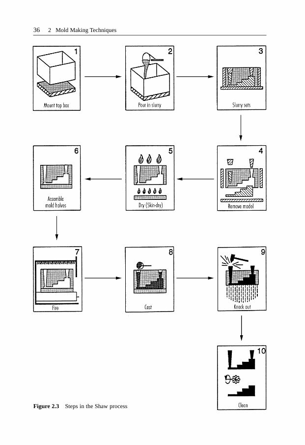
36 2 Mold Making Techniques
Figure 2.3 Steps in the Shaw process

372.2 Rapid Tooling for Injection Molds
2.2.1 State of the Art
A breakdown of all RT techniques is shown in Figure 2.4. The material additive pro-cesses lead fastest to moldings and are therefore the most promising. These also includenew and further developments in RP. Examples of such techniques are laser sintering,laser-generated RP and stereolithography, which enable mold inserts to be made directlyfrom a three-dimensional CAD model of the desired mold.
RT also covers conventional processes for removal or coating. These include high-speedcutting (HSC) [2.10] with direct control through the processing program generated bythe computer from the CAD model; erosion with rapidly machining graphite electrodes;and metal spraying, which has been used for decades in mold making.
Master molding techniques like precision and resin casting may be considered asbelonging to RT. These process chains become rapid tooling techniques when an RPtechnique is used to produce the necessary master mold.
Whereas, in the techniques mentioned so far, the prototype mold is produced eitherdirectly by means of a material additive method or in several processing stages, the so-called hybrid techniques integrate several such stages in one item of equipment. Theseprocessing stages are a combination of processes from the other three groups(conventional, master-molding, and material additive techniques). Because hybridtechniques combine sequential processes in unit, they can be just as fast as the materialadditive techniques. All these techniques are still in one development, however.
For a better understanding of the diverse processes and combinations involved, thedifferent RT techniques will be presented and discussed in this chapter.
Figure 2.5 illustrates the general procedure for RT. All methods rely on the existenceof consistent 3D CAD data that can be converted into closed volume elements. Thesedata are processed and sliced into layers. 2D horizontally stacked, parallel layers are thusgenerated inside the computer that, with the aid of a technique such as laser sintering,
Figure 2.4 Classification of RT processes

38 2 Mold Making Techniques
can be successively created within a few hours without the use of tools or a mold [2.11].Furthermore, there is generally no need for supervision by an operative.
To an extent depending on the principle underlying the chosen RT method, either apositive pattern, i.e. the molding to be fabricated later, or a negative pattern (the requi-site mold geometry) is produced. Once a physical positive pattern has been produced,usually any number of moldings may be made by master-molding and coating tech-niques, which will ultimately lead to a prototype mold after one or more stages.Examples of such process chains are resin casting and metal spraying.
The systematic use of 3D CAD systems during design affords a simple means ofgenerating mold cavities. Most 3D CAD systems already contain modules that canlargely perform a conversion from positive to negative automatically.
Once the data have been prepared thus, there are two possibilities to choose from. Oneis to create a physical model of the moving and fixed mold halves (negative patterns) soas to make a certain number of moldings that will lead to a mold. Metal casting is anexample of this. Alternatively, the negatives, perhaps made by stereolithography, may beelectrostatically coated. This process chain is shorter than the molding chain justmentioned.
Because the possibilities presented so far involve a sequence of different processes,they are known as indirect tooling. By contrast, direct tooling involves using thegenerated negative data without intervening steps to produce on an RP/RT system, as isthe case with selective laser sintering. Although this is undoubtedly a particularly fastoption, the boundary conditions need closer examination. Some of the resultant moldsentail laborious postmachining, which is more time consuming.
A major criterion other than subdivision into direct and indirect RT is the choice oftooling material. These are either metallic or so-called substitute materials, the latterusually being filled epoxy resins, two-component polyurethane systems, silicone rubber[2.12] or ceramics.
The more important and promising RT methods are presented below.
Figure 2.5 Basic approaches to RT

392.2 Rapid Tooling for Injection Molds
2.2.2 Direct Rapid Tooling
The goal of all developments in the field of RT is automated, direct fabrication ofprototype molds, whose properties approach those of production parts, from 3D CADdata describing the mold geometry. This data set must already allow for technical aspectsof molds, such as drafts, allowance for dimensional shrinkage and shrinkage parametersfor the RT process.
Processes for the direct fabrication of metallic and nonmetallic molds are presentedbelow. In either case, the mold may be made from the CAD data direct.
2.2.2.1 Direct Fabrication of Metallic Molds
Direct fabrication of prototype molds encompasses conventional methods that allowrapid processing (machining) of, e.g. aluminum.
2.2.2.1.1 Generative MethodsA common feature of generative methods for making metallic molds is that theworkpiece is formed by addition of material or the transition of a material from the liquidor powder state into the solid state, and not by removal of material as is the case withconventional production methods.
All the processes involved here have been developed out of RP methods (e.g. selectivelaser sintering, 3D printing, metal LOM (Laminated Object Manufacturing), shapemelting, and multiphase jet solidification) or utilize conventional techniques augmentedby layered structuring (laser-generated RP, controlled metal build-up).
In selective laser sintering (SLS) of metals, a laser beam melts powder startingmaterials layer by layer, with the layer thickness varying from 0.1 to 0.4 mm in line withthe particle size of the metal powder [2.13, 2.14]. The mold is thus generated layer bylayer.
Sintering may be performed indirectly and directly. In the indirect method (DTMprocess), metal powder coated with binder is sintered in an inert work chamber (e.g.flooded with nitrogen). Heated to a temperature just below the melting point of thebinder, the powder is applied thinly by a roller and melted at selected sites. The geometryof the desired mold inserts is thus obtained by melting the polymer coating. The resultantgreen part, which has low mechanical strength, is then heat-treated. The polymer binderis burned out at elevated temperatures to produce the brown part, which is then sinteredat a higher temperature. At an even higher temperature again, the brown part is infiltratedwith copper (at approx. 1120 °C), solder alloy or epoxy resin [2.15], this serving to sealthe open pores that were formed when the polymer binder was removed (Figure 2.6).
In direct laser sintering manufacture, metals are sintered in the absence of binder(EOS process). The advantage of not using coated powders is that the laborious removalof binder, and the possibility of introducing inaccuracies into the processing stage, canbe dispensed with. Nevertheless, the part must be infiltrated since it has only provedpossible so far to sinter parts to 70% of the theoretical density [2.16]. After infiltration,posttreatment is necessary and generally takes the form of polishing.
Aside from pure metal powders and powders treated with binder, multicomponentmetallic powders are used. These consist of a powder mixture containing at least twometals that can also be used in the direct sintering process. The lower-meltingcomponent provides the cohesion in the SLS preform and the higher-melting componentmelts in the furnace to imbue the mold with its ultimate strength. Candidate metals and

40 2 Mold Making Techniques
metal alloys for direct and indirect sintering are, according to [2.17]: aluminum, alu-minum bronze, copper, nickel, steel, nickel-bronze powder and stainless steel. Themaximum size capable of being made by laser sintering is currently 250 · 250 · 150 mm3.
Another way to apply metal is by laser-generated RP. Powder is continually added tothe melt in a movable process head [2.18]. The added material combines with the meltedmaterial on the preceding layer. The layers can be added in thicknesses of 0.5 to 3 mm.Metal powder is blown in and melted in a focused laser beam. As the process head movesrelative to the work surface, fine beads of metal are formed. The materials used arechrome and nickel alloys, copper and steel. Laser-generated RP is not as accurate as lasersintering and can only generate less complex geometries due to the process setup.
A further development of laser-generated RP is that of controlled metal build-up[2.19]. This is a combination of laser-generated RP and HSC milling (Figure 2.7). Oncea layer 0.1 to 0.15 mm thick has been generated by laser, it is then milled. This resultsin high contour accuracy of a level not previously possible with laser-generated RP.The maximum part size is currently 200 mm3 for medium complexity. No undercuts arepossible.
Other processes still undergoing development are shape melting and multiphase jetsolidification [2.20]. Both processes are similar to fused deposition modeling, which isan RP process [2.21]. In shape melting, a metal filament is melted in an arc anddeposited while, in multiphase jet solidification, melt-like material is applied layer bylayer via a nozzle system. Low-melting alloys and binders filled with stainless steel,ceramic or titanium powder are employed. As in SLS, the binder is burned out, and theworkpiece is infiltrated and polished. However, the two processes are still not asaccurate as SLS.
3D printing of metals is now being used to fabricate prototype molds for injectionmolding, but it is not yet commercially available. Figure 2.8 illustrates how the 3Dprinting process works. After a layer of metal powder has been applied, binder is appliedselectively by means of a traversing jet that is similar to an ink jet. This occurs at low
Figure 2.6 Indirect sintering followed by infiltration
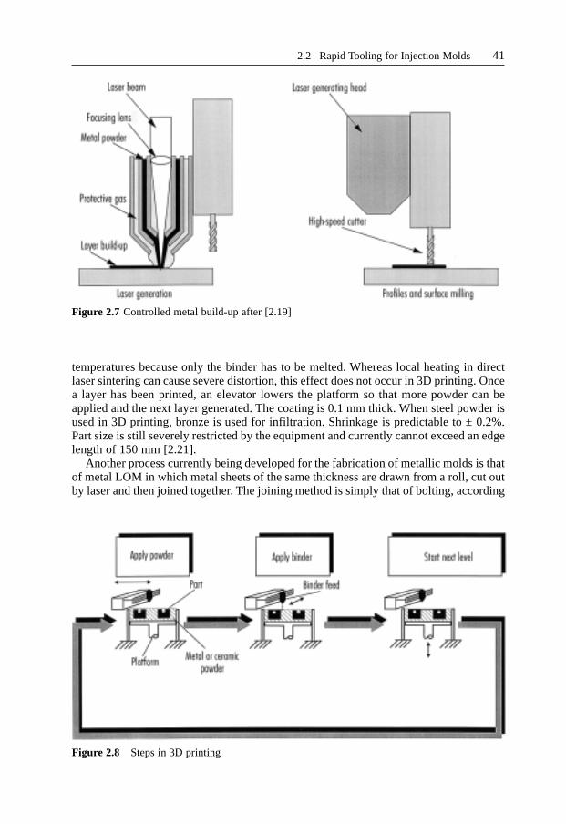
412.2 Rapid Tooling for Injection Molds
temperatures because only the binder has to be melted. Whereas local heating in directlaser sintering can cause severe distortion, this effect does not occur in 3D printing. Oncea layer has been printed, an elevator lowers the platform so that more powder can beapplied and the next layer generated. The coating is 0.1 mm thick. When steel powder isused in 3D printing, bronze is used for infiltration. Shrinkage is predictable to ± 0.2%.Part size is still severely restricted by the equipment and currently cannot exceed an edgelength of 150 mm [2.21].
Another process currently being developed for the fabrication of metallic molds is thatof metal LOM in which metal sheets of the same thickness are drawn from a roll, cut outby laser and then joined together. The joining method is simply that of bolting, according
Figure 2.7 Controlled metal build-up after [2.19]
Figure 2.8 Steps in 3D printing

to [2.22]. So far, molds made in this way have only been used for metal shaping and forinjection molding wax patterns for precision casting. The advantage of molds joined bybolts is that the geometry can be modified simply by swapping individual metal sheets.
The variant developed by [2.23] is a combination of laser cutting and diffusionwelding. Unlike metal LOM and most other RT processes, which grow the layers atconstant thickness, this process variant allows sheets of any thickness to be used. As aresult, simple geometric sections of a mold may be used as a compact segment, a factwhich allows RT only to be used where it is necessary and expedient. Possibledimensional accuracy is in the order of 0.1%. Due to the process itself, it is never lowerthan ± 0.1 mm in the build direction. The tolerances of laser cutting are from 0.001 to0.1 mm. Unlike most of the processes mentioned so far, this process imposes virtuallyno restrictions on part size [2.24].
Direct RT processes are still in their infancy. Apart from selective laser sintering and3D printing of metals, all the processes discussed in this section are still being developedand so are not yet available on the market. This explains why stereolithography, despitethe fact that it is a direct fabrication process involving nonmetallic materials, is virtuallythe only one used for these purposes. Because it has constantly evolved over the last 10years and is offered by many service providers, it is readily available. Moreover, manylarge companies are in possession of stereolithographic equipment and still elect to useit for making prototype molds.
2.2.2.1.2 Direct Fabrication of Nonmetallic MoldsWhile most direct methods for making metallic molds require posttreatment (infiltrationand mechanical finishing), the production of molds from auxiliary materials largelydispenses with this need.
Stereolithography (STL) is based on the curing of liquid, UV-curing polymers throughthe action of a computer-controlled laser. The laser beam traverses predeterminedcontours on the surface of a UV-curable photopolymer bath point by point, therebycuring the polymer. An elevator lowers the part so that the next layer can be cured. Oncethe whole part has been generated, it is postcured by UV radiation in a postcuringfurnace [2.24].
STL‘s potential lies in its accuracy, which is as yet unsurpassed. Because it was thefirst RP process to come onto the market, at the end of the 1980s, it has a head-start overother technologies. Ongoing improvements to the resins and the process have broughtabout the current accuracies of 0.04 mm in the x- and y-axes and 0.05 mm in the z-axis.
The process was originally developed for RP purposes but is also used for rapidtooling of injection molds because of its accuracy and the resultant good surfaces whichit produces. When STL is used to make a mold cavity, the mold halves are generated onthe machine and then mounted in a frame. Usually, however, the shell technique isemployed. In this, a shell of the mold contour is built by STL and then back-filled withfilled epoxy resin [2.25]. The use of the shell technique to produce such an RT mold isillustrated in Figure 2.9.
Parts made by stereolithography feature high precision and outstanding surfaceproperties. Unlike all other direct methods for making metallic molds, no furthertreatment is necessary other than posttreatment of the typical step-like structurestemming from the layered build-up by the RP/RT processes. This translates to aconsiderable advantage time-wise, particularly when the mold surfaces must be glossyand planar. The downside is the poor thermal and mechanical properties of the availableresins (acrylate, vinyl ether, epoxy), which cause the molds to have very short service
42 2 Mold Making Techniques

432.2 Rapid Tooling for Injection Molds
lives. The best dimensional and surface properties are obtained with epoxy resins; theuse of particularly powerful lasers makes for faster, more extensive curing of the resineven during the stereolithography process, and this in turn minimizes distortion [2.26].
Although STL has primarily been used for RP, the number of RT applications is onthe increase. It is used to make molds for casting wax patterns as well as for injectionmolding thermoplastics. Such molds serve in the production of parts for a pilot series,which can yield important information about the filling characteristics of the cavities.Moreover, it is even possible to identify fabrication problems at this very early stage.
Ceramics are other materials used for direct rapid tooling. Bettany [2.27] has reportedon the use of ceramic molds for injection molding. They are employed in the 3D printingprocess described in the previous section as well as in ballistic particle manufacturing(droplets of the melted material are deposited by means of piezoelectric ink-jet nozzle).The advantage over metallic molds is the high strength of ceramic molds. This comesparticularly to the fore when abrasive, filled polymers are processed.
2.2.3 Indirect Rapid Tooling (Multistage Process Chains)
An RT chain is defined here as a succession of individual molding stages. The use ofsuch a molding chain leads from a master pattern to a cavity that may be used forinjection molding. In the sense of this definition, intermediate stages such as machiningor simple assembly of already finished cavity modules do not count as individual linksin this chain. A good RT chain is notable on the one hand for having a minimum numberof molding stages (chain links). The lower the number of molding stages, the moreaccurately the part matches the master pattern and the faster a prototype mold can bemade. Every intermediate pattern can only be as good as the pattern from which it
Figure 2.9 The shell technique for generating an STL mold