mep 480 b.sc. design project - july 2016/2017 design of an
TRANSCRIPT
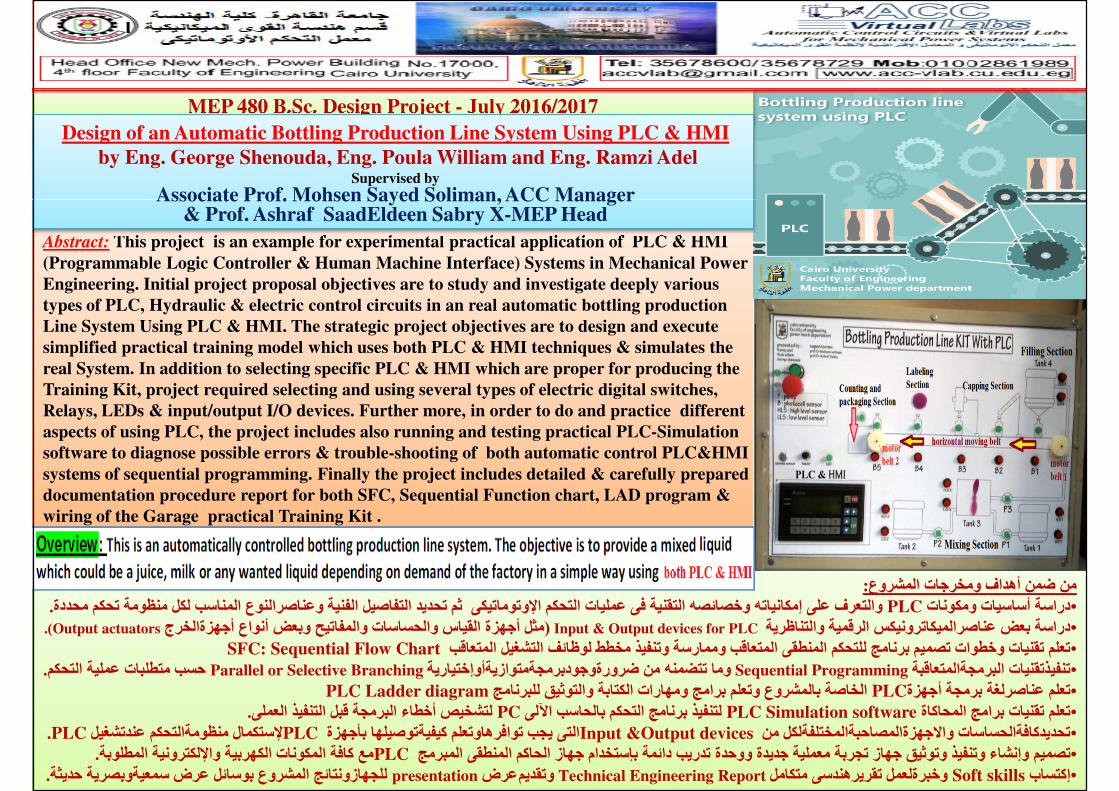
Abstract: This project is an example for experimental practical application of PLC & HMI
(Programmable Logic Controller & Human Machine Interface) Systems in Mechanical Power
MEP 480 B.Sc. Design Project - July 2016/2017
Design of an Automatic Bottling Production Line System Using PLC & HMI
by Eng. George Shenouda, Eng. Poula William and Eng. Ramzi AdelSupervised by
Associate Prof. Mohsen Sayed Soliman, ACC Manager & Prof. Ashraf SaadEldeen Sabry X-MEP Head
(Programmable Logic Controller & Human Machine Interface) Systems in Mechanical Power
Engineering. Initial project proposal objectives are to study and investigate deeply various
types of PLC, Hydraulic & electric control circuits in an real automatic bottling production
Line System Using PLC & HMI. The strategic project objectives are to design and execute
simplified practical training model which uses both PLC & HMI techniques & simulates the
real System. In addition to selecting specific PLC & HMI which are proper for producing the
Training Kit, project required selecting and using several types of electric digital switches,
Relays, LEDs & input/output I/O devices. Further more, in order to do and practice different
aspects of using PLC, the project includes also running and testing practical PLC-Simulation
software to diagnose possible errors & trouble-shooting of both automatic control PLC&HMI
systems of sequential programming. Finally the project includes detailed & carefully prepared
documentation procedure report for both SFC, Sequential Function chart, LAD program &
wiring of the Garage practical Training Kit .
:من ضمن أھداف ومخرجات المشروع
.كم محددةتحوالتعرف على إمكانياته وخصائصه التقنية فى عمليات التحكم ا*وتوماتيكى ثم تحديد التفاصيل الفنية وعناصرالنوع المناسب لكل منظومة PLCدراسة أساسيات ومكونات •& Inputدراسة بعض عناصرالميكاترونيكس الرقمية والتناظرية • Output devices for PLC ) مثل أجھزة القياس والحساسات والمفاتيح وبعض أنواع أجھزةالخرجOutput actuators(. SFC: Sequential Flow Chartتعلم تقنيات وخطوات تصميم برنامج للتحكم المنطقى المتعاقب وممارسة وتنفيذ مخطط لوظائف التشغيل المتعاقب •
. حسب متطلبات عملية التحكم Parallel or Selective Branchingوما تتضمنه من ضرورةوجودبرمجةمتوازيةأوإختيارية Sequential Programmingتنفيذتقنيات البرمجةالمتعاقبة• PLC Ladder diagramالخاصة بالمشروع وتعلم برامج ومھارات الكتابة والتوثيق للبرنامج PLCتعلم عناصرلغة برمجة أجھزة•
.لتشخيص أخطاء البرمجة قبل التنفيذ العملى PCلتنفيذ برنامج التحكم بالحاسب اQلى PLC Simulation softwareتعلم تقنيات برامج المحاكاة •.PLC*ستكمال منظومةالتحكم عندتشغيل PLCالتى يجب توافرھاوتعلم كيفيةتوصيلھا بأجھزة Input &Output devicesتحديدكافةالحساسات واTجھزةالمصاحبةالمختلفةلكل من •.مع كافة المكونات الكھربية وا*لكترونية المطلوبةPLCتصميم وإنشاء وتنفيذ وتوثيق جھاز تجربة معملية جديدة ووحدة تدريب دائمة بإستخدام جھاز الحاكم المنطقى المبرمج •.للجھازونتائج المشروع بوسائل عرض سمعيةوبصرية حديثة presentationعرض وتقديم Technical Engineering Reportوخبرةلعمل تقريرھندسى متكامل Soft skillsإكتساب •
PLC_Student_Real_Project_Bottle_Filling_Capping_machine.mp4
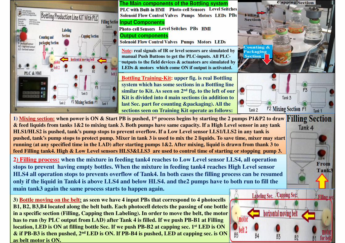
Note: real signals of IR or level sensors are simulated by
manual Push Buttons to get the PLC-inputs. All PLC-
outputs to the field devices & actuators are simulated by
LEDs & motors which come ON if output is activated.
Bottling Training-Kit: upper fig. is real Bottling
1) Mixing section: when power is ON & Start PB is pushed, 1st process begins by starting the 2 pumps P1&P2 to draw
& feed liquids from tanks 1&2 to mixing tank 3. Both pumps have same capacity. If a High Level sensor in any tank
HLS1/HLS2 is pushed, tank’s pump stops to prevent overflow. If a Low Level sensor LLS1/LLS2 in any tank is
pushed, tank’s pump stops to protect pump. Mixer in tank 3 is used to mix the 2 liquids. To save time, mixer may start
running (at any specified time in the LAD) after starting pumps 1&2. After mixing, liquid is drawn from thank 3 to
feed Filling tank4. High & Low Level sensors HLS3&LLS3 are used to control time of starting or stopping pump 3.
system which has some sections in a Bottling line
similar to Kit. As seen on 2nd fig. to the left of our
Kit is divided into 4 main sections (in addition to
last Sec. part for counting &packaging). All the
sections seen on Training Kit operate as follows:
2) Filling process: when the mixture in feeding tank4 reaches to Low Level sensor LLS4, all operation 2) Filling process: when the mixture in feeding tank4 reaches to Low Level sensor LLS4, all operation
stops to prevent having empty bottles. When the mixture in feeding tank4 reaches High Level sensor
HLS4 all operation stops to prevents overflow of Tank4. In both cases the filling process can be resumed
only if the liquid in Tank4 is above LLS4 and below HLS4. and the2 pumps have to both run to fill the
main tank3 again the same process starts to happen again.
3) Bottle moving on the belt: as seen we have 4 input PBs that correspond to 4 photocells
B1, B2, B3,B4 located along the belt bath. Each photocell detects the passing of one bottle
in a specific section (Filling, Capping then Labeling). In order to move the belt, the motor
has to run (by PLC output from LAD) after Tank 4 is filled. If we push PB-B1 at Filling
location, LED is ON at filling bottle Sec. If we push PB-B2 at capping sec. 1st LED is ON
& if PB-B3 is then pushed, 2nd LED is ON. If PB-B4 is pushed, LED at capping sec. is ON
as belt motor is ON.
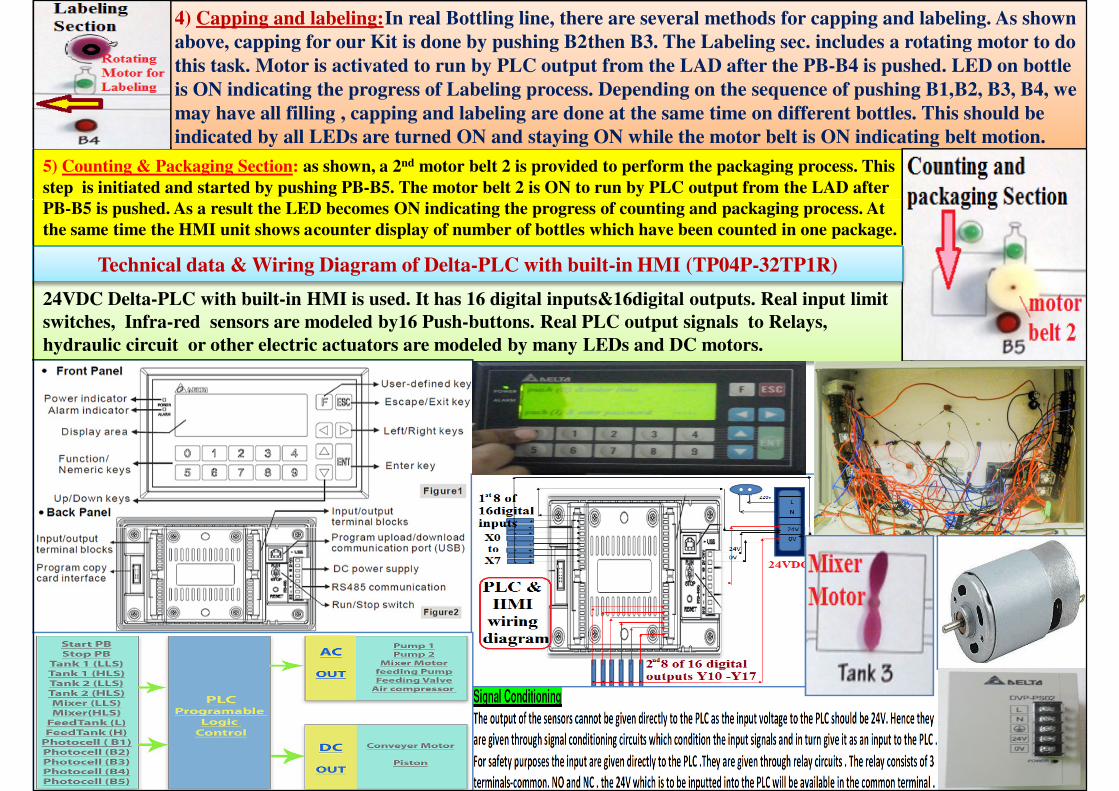
4) Capping and labeling:In real Bottling line, there are several methods for capping and labeling. As shown
above, capping for our Kit is done by pushing B2then B3. The Labeling sec. includes a rotating motor to do
this task. Motor is activated to run by PLC output from the LAD after the PB-B4 is pushed. LED on bottle
is ON indicating the progress of Labeling process. Depending on the sequence of pushing B1,B2, B3, B4, we
may have all filling , capping and labeling are done at the same time on different bottles. This should be
indicated by all LEDs are turned ON and staying ON while the motor belt is ON indicating belt motion.
5) Counting & Packaging Section: as shown, a 2nd motor belt 2 is provided to perform the packaging process. This
step is initiated and started by pushing PB-B5. The motor belt 2 is ON to run by PLC output from the LAD after
PB-B5 is pushed. As a result the LED becomes ON indicating the progress of counting and packaging process. At
the same time the HMI unit shows acounter display of number of bottles which have been counted in one package.
Technical data & Wiring Diagram of Delta-PLC with built-in HMI (TP04P-32TP1R)
24VDC Delta-PLC with built-in HMI is used. It has 16 digital inputs&16digital outputs. Real input limit
switches, Infra-red sensors are modeled by16 Push-buttons. Real PLC output signals to Relays,
hydraulic circuit or other electric actuators are modeled by many LEDs and DC motors.
Technical data & Wiring Diagram of Delta-PLC with built-in HMI (TP04P-32TP1R)
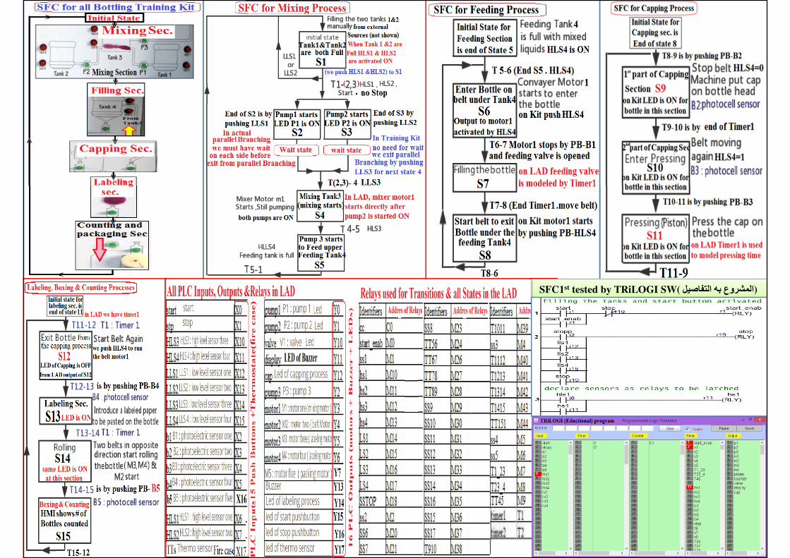
SFC1st tested by TRiLOGI SW( المشروع به التفاصيل)

LAD on ISPصورلكل تفاصيل برنامج يوجدبالمشروع
على البرنامج محاكاةتشغيل صوركثيرةمن المشروع يوجدفى
PLCعملى ب تشغيله أخطاءالبرمجةقبل لتشخيص الحاسب
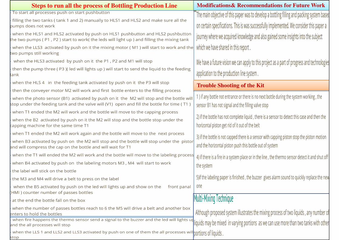
Steps to run all the process of Bottling Production Line Modifications& Recommendations for Future Work
Trouble Shooting of the Kit