meraki mr24 - rho wirelessrhowireless.com/hardware/mesh/docs/meraki_setup_mr24.pdf · meraki,...
TRANSCRIPT
Meraki MR24Hardware Installation Guide
TrademarksMeraki, Meraki MR24, Meraki Cloud Controller, and Meraki Mesh are trademarks of Meraki, Inc. Other brand and product names are registered trademarks or trademarks of their respective holders. Statement of Conditions In the interest of improving internal design, operational function, and/or reliability, Meraki reserves the right to make changes to the products described in this document without notice. Meraki does not assume any liability that may occur due to the use or application of the product(s) or circult layout(s) described herein.
WarrantyMeraki, Inc. provides a lifetime warranty on this product. Warranty details may be found at www.meraki.com/legal.
3
Table of Contents 1 Scope of Document and Related Publications 4
2 MR24 Overview 5 2.1 Package Contents 5 2.2 Understanding the MR24 5 2.3 Security Features 7 2.4 Ethernet Ports 7 2.5 Power Source Options 7 2.6 Factory Reset Button 7 2.7 LED Indicators and Run Dark Mode 7 2.8 UL 2043 Plenum rating 8
3 Pre-Install Preparation 8 3.1 Configure Your Network in Dashboard 8 3.2 Check and Upgrade Firmware 8 3.3 Check and Configure Firewall Settings 8 3.4 Assigning IP Addresses to MR24s 9 3.4.1 Dynamic Assignment 9 3.4.2 Static Assignment 9 3.4.3 Static IP Assignment via DHCP Reservations 9 3.5 Collect Tools 10 3.6 Collect Additional Hardware for Installation 10
4 Installation Instructions 11 4.1 Choose Your Mounting Location 11 4.2 Install the MR24 11 4.2.1 Attach the Mount Plate 11 4.2.1.1 Wall or Solid Ceiling Mount Using Mount Plate 13 4.2.1.2 Drop Ceiling Mount Using Mount Plate 14 4.2.1.3 Electrical Junction Box Mount Using Mount Plate 18 4.2.1.4 Plenum Mount (Above Drop Ceiling) 19 4.2.2 Power the MR24 20 4.2.2.1 Powering the MR24 with Meraki AC Adapter 21 4.2.2.2 Powering the MR24 with Meraki 802.3af Power over Ethernet Injector 21 4.2.2.3 Powering the MR24 with an 802.3af Power over Ethernet Switch 22 4.2.3 Mount the MR24 22 4.2.3.1 Assemble Security Hasp to the MR24 22 4.2.3.2 Assemble MR24 to the Mount Plate 23 4.2.3.3 Desk or Shelf Mount 25 4.2.3.4 Wall or Solid Ceiling Mount without Mount Plate 25 4.3 Secure the MR24 26 4.3.1 Security Screw 26 4.3.2 Pad Lock 26 4.3.2 Kensington Lock 26 4.4 Verify Device Functionality and Test Network Coverage 27
5 Troubleshooting 27
6 Regulatory Information for MR24 28
4
1 Scope of Document and Related Publications
The MR24 Hardware Installation Guide describes the installation procedure for the MR24 access point.
Additional reference documents are available online at www.meraki.com/library/product.
5
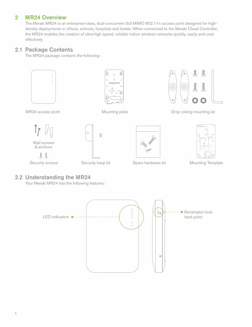
MR24 access point Drop ceiling mounting kit
2 MR24 Overview The Meraki MR24 is an enterprise-class, dual-concurrent 3x3 MIMO 802.11n access point designed for high- density deployments in offices, schools, hospitals and hotels. When connected to the Meraki Cloud Controller, the MR24 enables the creation of ultra-high speed, reliable indoor wireless networks quickly, easily and cost- effectively.
2.1 Package Contents The MR24 package contains the following:
2.2 Understanding the MR24 Your Meraki MR24 has the following features:
Kensington lock hard point
Spare hardware kitSecurity hasp kitSecurity screws
Wall screws & anchors
LED indicators
Mounting Template
Mounting plate
6
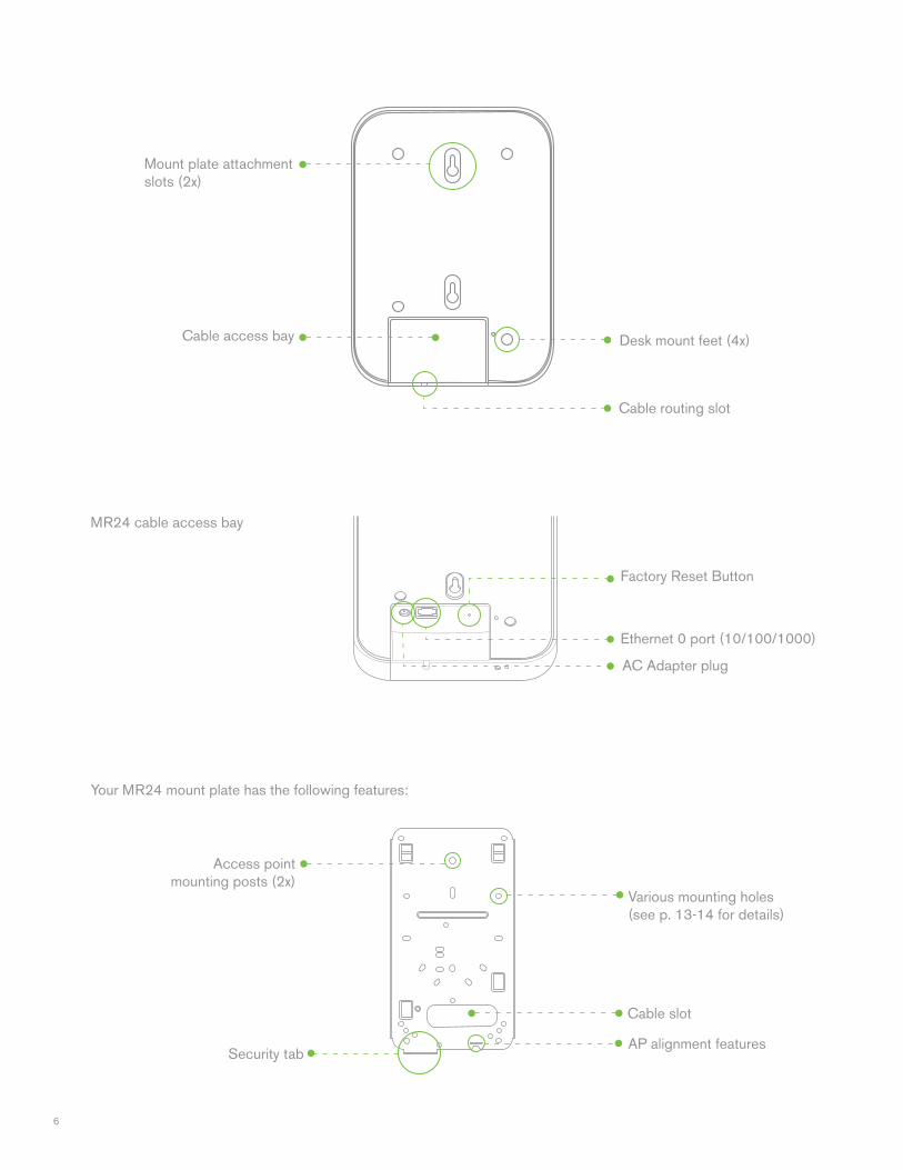
Cable slot
Security tab
Your MR24 mount plate has the following features:
MR24 cable access bay
Mount plate attachment slots (2x)
Access point mounting posts (2x)
Desk mount feet (4x)
Cable routing slot
Cable access bay
AC Adapter plug
Ethernet 0 port (10/100/1000)
Factory Reset Button
Various mounting holes (see p. 13-14 for details)
AP alignment features
7
2.3 Security Features The MR24 features multiple options for physically securing the access point after installation: 1. Security screw – The accessory kit includes screws that can be used to secure the access point to the mount plate. Engaging the security screw prevents accidental dislodging and theft. 2. Kensington lock – The access point contains a hard point that allows it to be secured to any nearby permanent structure using a standard Kensington lock.
2.4 Ethernet Ports Both MR24 and MR24 feature a Gigabit Ethernet RJ45 port that accepts 802.3af power (labeled “Eth0, PoE”). This port should be used for uplink to your WAN connection.
2.5 Power Source Options The MR24 access point can be powered using either the Meraki AC Adapter or 802.3af PoE Injector (both sold separately) or a third-party 802.3af PoE switch.
2.6 Factory Reset Button If the button is pressed and held for at least five seconds and then released, the MR24 will reboot and be restored to its original factory settings by deleting all configuration information stored on the unit.
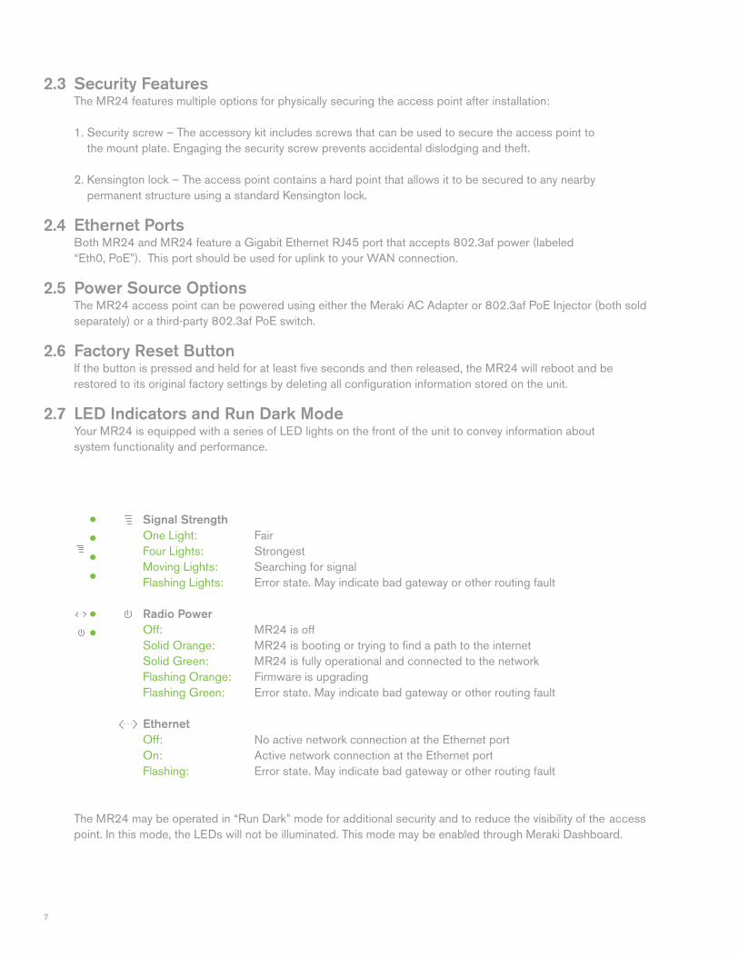
2.7 LED Indicators and Run Dark Mode Your MR24 is equipped with a series of LED lights on the front of the unit to convey information about system functionality and performance.
The MR24 may be operated in “Run Dark” mode for additional security and to reduce the visibility of the access point. In this mode, the LEDs will not be illuminated. This mode may be enabled through Meraki Dashboard.
Signal Strength One Light: Fair Four Lights: Strongest Moving Lights: Searching for signal Flashing Lights: Error state. May indicate bad gateway or other routing fault
Radio PowerOff: MR24 is off Solid Orange: MR24 is booting or trying to find a path to the internet Solid Green: MR24 is fully operational and connected to the network Flashing Orange: Firmware is upgrading Flashing Green: Error state. May indicate bad gateway or other routing fault Ethernet Off: No active network connection at the Ethernet port On: Active network connection at the Ethernet port Flashing: Error state. May indicate bad gateway or other routing fault
8
2.8 UL 2043 Plenum rating The MR24 meets the UL 2043 plenum-rating standard. This certifies that the MR24 has adequate fire resistance and low smoke-emission characteristics to be mounted and operated in a building’s environmental air spaces, such as above suspended ceilings in an office environment.
3 Pre-Install Preparation You should complete the following steps before going on-site to perform an installation.
3.1 Configure Your Network in Dashboard The following is a brief overview only of the steps required to add an MR24 to your network. For detailed instructions about creating, configuring and managing Meraki wireless networks, refer to the Meraki Cloud Controller Manual (meraki.com/library/product). 1. Login to http://dashboard.meraki.com. If this is your first time, create a new account. 2. Find the network to which you plan to add your APs or create a new network. 3. Add your APs to your network. You will need your Meraki order number (found on your invoice if you ordered directly from Meraki) or the serial number of each AP, which looks like Qxxx-xxxx-xxxx, and is found on the bottom of the unit. You will also need your Enterprise Cloud Controller license key, which you should have received via email from [email protected]. 4. Go to the map / floor plan view and place each AP on the map by clicking and dragging it to the location where you plan to mount it.
3.2 Check and Upgrade Firmware To ensure your MR24 performs optimally immediately following installation, Meraki recommends that you facilitate a firmware upgrade prior to mounting your MR24. 1. Attach your MR24 to power and a wired Internet connection. See p. 19 of this Hardware Installation Guide for details. 2. The MR24 will turn on and the Power LED will glow solid orange. If the unit does not require a firmware upgrade, the Power LED will turn green within thirty seconds. * If the unit requires an upgrade, the Power LED will begin blinking orange until the upgrade is complete, at which point the Power LED will turn solid green. You should allow about an hour for the firmware upgrade to complete, depending on the speed of your internet connection. 3.3 Check and Configure Firewall Settings If a firewall is in place, it must allow outgoing connections on particular ports to particular IP addresses. The most current list of outbound ports and IP addresses can be found here: http://tinyurl.com/y79une3
9
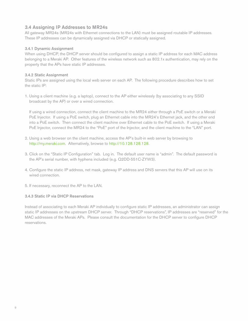
3.4 Assigning IP Addresses to MR24s All gateway MR24s (MR24s with Ethernet connections to the LAN) must be assigned routable IP addresses. These IP addresses can be dynamically assigned via DHCP or statically assigned.
3.4.1 Dynamic Assignment When using DHCP, the DHCP server should be configured to assign a static IP address for each MAC address belonging to a Meraki AP. Other features of the wireless network such as 802.1x authentication, may rely on the property that the APs have static IP addresses. 3.4.2 Static Assignment Static IPs are assigned using the local web server on each AP. The following procedure describes how to set the static IP: 1. Using a client machine (e.g. a laptop), connect to the AP either wirelessly (by associating to any SSID broadcast by the AP) or over a wired connection. If using a wired connection, connect the client machine to the MR24 either through a PoE switch or a Meraki PoE Injector. If using a PoE switch, plug an Ethernet cable into the MR24’s Ethernet jack, and the other end into a PoE switch. Then connect the client machine over Ethernet cable to the PoE switch. If using a Meraki PoE Injector, connect the MR24 to the “PoE” port of the Injector, and the client machine to the “LAN” port. 2. Using a web browser on the client machine, access the AP’s built-in web server by browsing to http://my.meraki.com. Alternatively, browse to http://10.128.128.128.
3. Click on the “Static IP Configuration” tab. Log in. The default user name is “admin”. The default password is the AP’s serial number, with hyphens included (e.g. Q2DD-551C-ZYW3).
4. Configure the static IP address, net mask, gateway IP address and DNS servers that this AP will use on its wired connection.
5. If necessary, reconnect the AP to the LAN.
3.4.3 Static IP via DHCP Reservations
Instead of associating to each Meraki AP individually to configure static IP addresses, an administrator can assign static IP addresses on the upstream DHCP server. Through “DHCP reservations”, IP addresses are “reserved” for the MAC addresses of the Meraki APs. Please consult the documentation for the DHCP server to configure DHCP reservations.
10
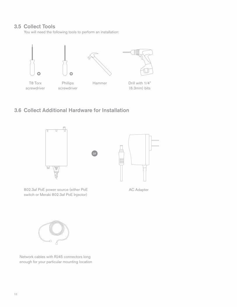
T8 Torxscrewdriver
Phillips screwdriver
Hammer Drill with 1/4” (6.3mm) bits
3.6 Collect Additional Hardware for Installation
802.3af PoE power source (either PoE switch or Meraki 802.3af PoE Injector)
Network cables with RJ45 connectors long enough for your particular mounting location
3.5 Collect Tools You will need the following tools to perform an installation:
AC Adapter
or
11
4 Installation Instructions
4.1 Choose Your Mounting Location A good mounting location is important to getting the best performance out of your MR24 access point. Keep the following in mind: 1. The device should have unobstructed line of sight to most coverage areas. For example, if installing in an office filled with workspaces divided by mid-height cubicle walls, installing on the ceiling or high on a wall would be ideal. 2. Power over Ethernet supports a maximum cable length of 300 ft (100 m). 3. If being used in a mesh deployment, the MR24 should have line of sight to at least two other Meraki devices. For more detailed instructions regarding access point location selection, reference the Meraki Network Design Guide (meraki.com/library/product).
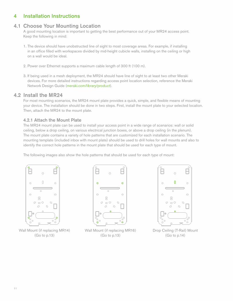
4.2 Install the MR24 For most mounting scenarios, the MR24 mount plate provides a quick, simple, and flexible means of mounting your device. The installation should be done in two steps. First, install the mount plate to your selected location. Then, attach the MR24 to the mount plate.
4.2.1 Attach the Mount Plate The MR24 mount plate can be used to install your access point in a wide range of scenarios: wall or solid ceiling, below a drop ceiling, on various electrical junction boxes, or above a drop ceiling (in the plenum). The mount plate contains a variety of hole patterns that are customized for each installation scenario. The mounting template (included inbox with mount plate) should be used to drill holes for wall mounts and also to identify the correct hole patterns in the mount plate that should be used for each type of mount.
The following images also show the hole patterns that should be used for each type of mount:
Wall Mount (if replacing MR14)(Go to p.13)
Drop Ceiling (T-Rail) Mount(Go to p.14)
Wall Mount (if replacing MR16)(Go to p.13)
12
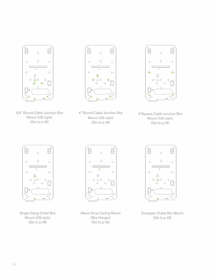
3.5” Round Cable Junction Box Mount (US style)
(Go to p.18)
Single-Gang Outlet Box Mount (US style)
(Go to p.18)
Above Drop Ceiling Mount(Box Hanger)(Go to p.19)
4” Round Cable Junction Box Mount (US style)
(Go to p.18)
4”Square Cable Junction Box Mount (US style)
(Go to p.18)
European Outlet Box Mount(Go to p.18)
13
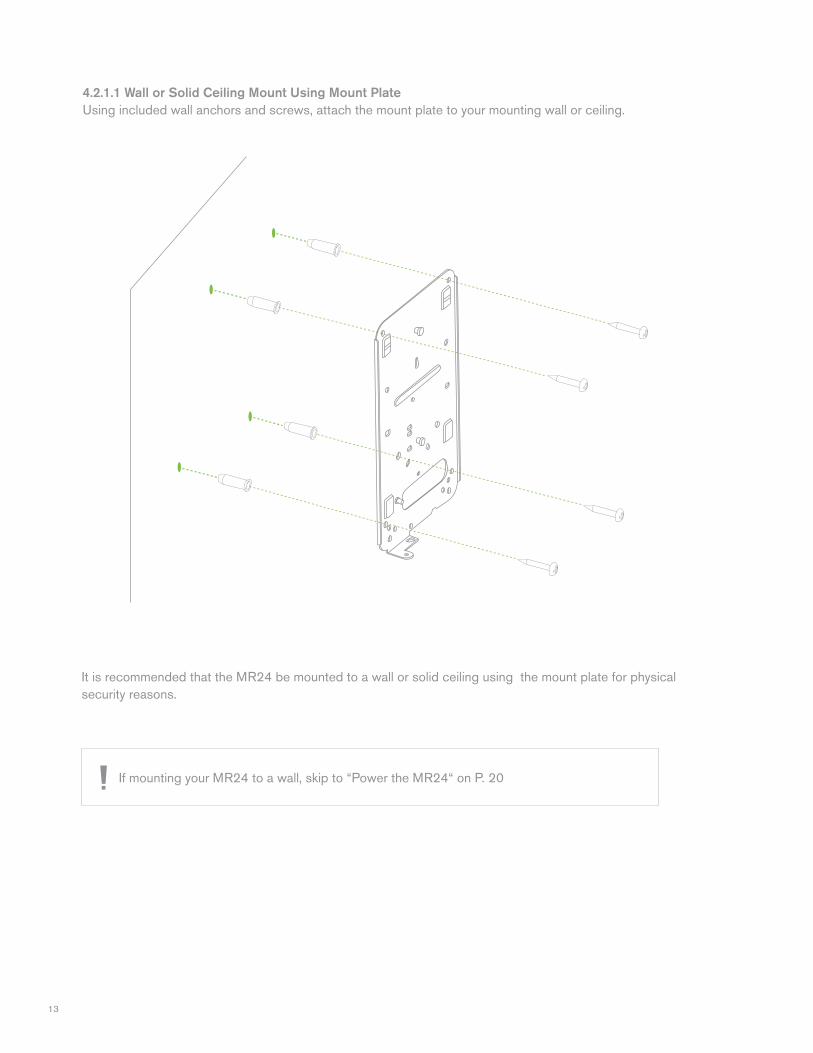
4.2.1.1 Wall or Solid Ceiling Mount Using Mount PlateUsing included wall anchors and screws, attach the mount plate to your mounting wall or ceiling.
It is recommended that the MR24 be mounted to a wall or solid ceiling using the mount plate for physical security reasons.
If mounting your MR24 to a wall, skip to “Power the MR24“ on P. 20
14
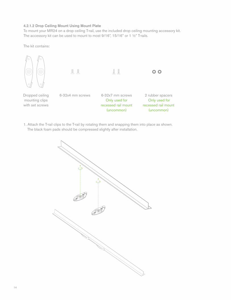
1. Attach the T-rail clips to the T-rail by rotating them and snapping them into place as shown. The black foam pads should be compressed slightly after installation.
4.2.1.2 Drop Ceiling Mount Using Mount PlateTo mount your MR24 on a drop ceiling T-rail, use the included drop ceiling mounting accessory kit. The accessory kit can be used to mount to most 9/16”, 15/16” or 1 ½” T-rails.
Dropped ceiling mounting clipswith set screws
6-32x4 mm screws 6-32x7 mm screwsOnly used for
recessed rail mount (uncommon)
2 rubber spacers Only used for
recessed rail mount (uncommon)
The kit contains:
15
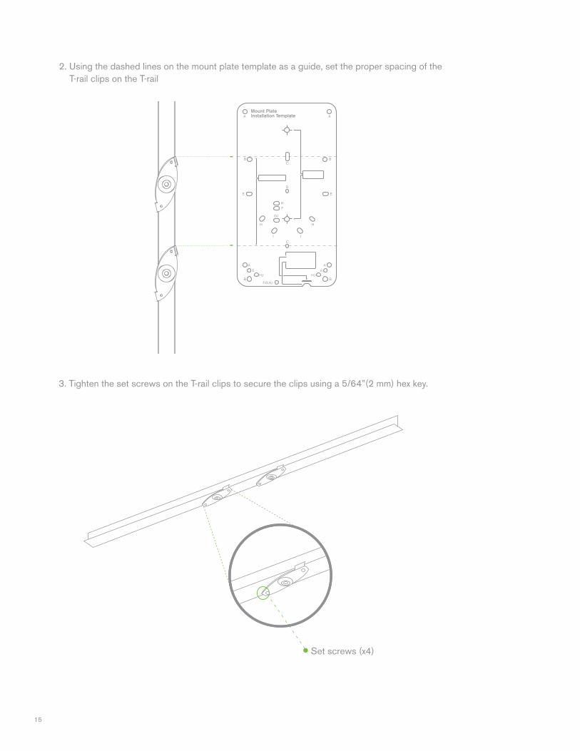
3. Tighten the set screws on the T-rail clips to secure the clips using a 5/64”(2 mm) hex key.
2. Using the dashed lines on the mount plate template as a guide, set the proper spacing of the T-rail clips on the T-rail
Set screws (x4)
16
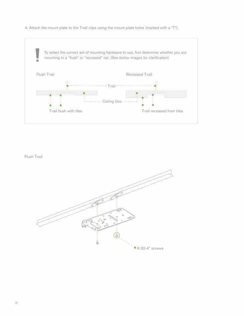
4. Attach the mount plate to the T-rail clips using the mount plate holes (marked with a “T“).
To select the correct set of mounting hardware to use, first determine whether you are mounting to a “flush” or “recessed“ rail. (See below images for clarification)
Flush T-rail Recessed T-rail
T-rail flush with tiles T-rail recessed from tiles
Ceiling tiles
T-rail
6-32-4” screws
Flush T-rail
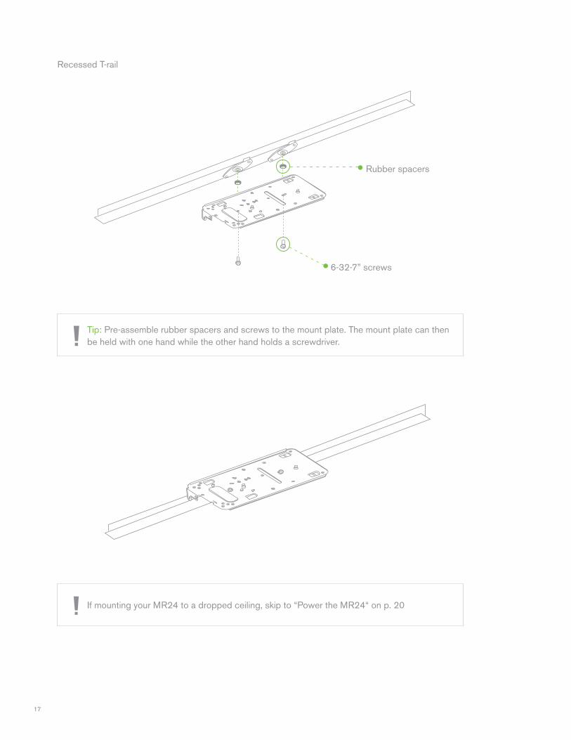
17
Rubber spacers
6-32-7” screws
Tip: Pre-assemble rubber spacers and screws to the mount plate. The mount plate can then be held with one hand while the other hand holds a screwdriver.
If mounting your MR24 to a dropped ceiling, skip to “Power the MR24“ on p. 20
Recessed T-rail
18
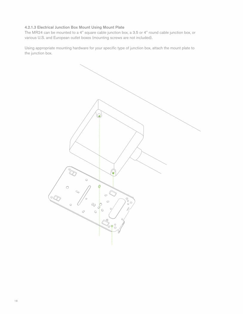
4.2.1.3 Electrical Junction Box Mount Using Mount PlateThe MR24 can be mounted to a 4” square cable junction box, a 3.5 or 4” round cable junction box, or various U.S. and European outlet boxes (mounting screws are not included).
Using appropriate mounting hardware for your specific type of junction box, attach the mount plate to the junction box.
19
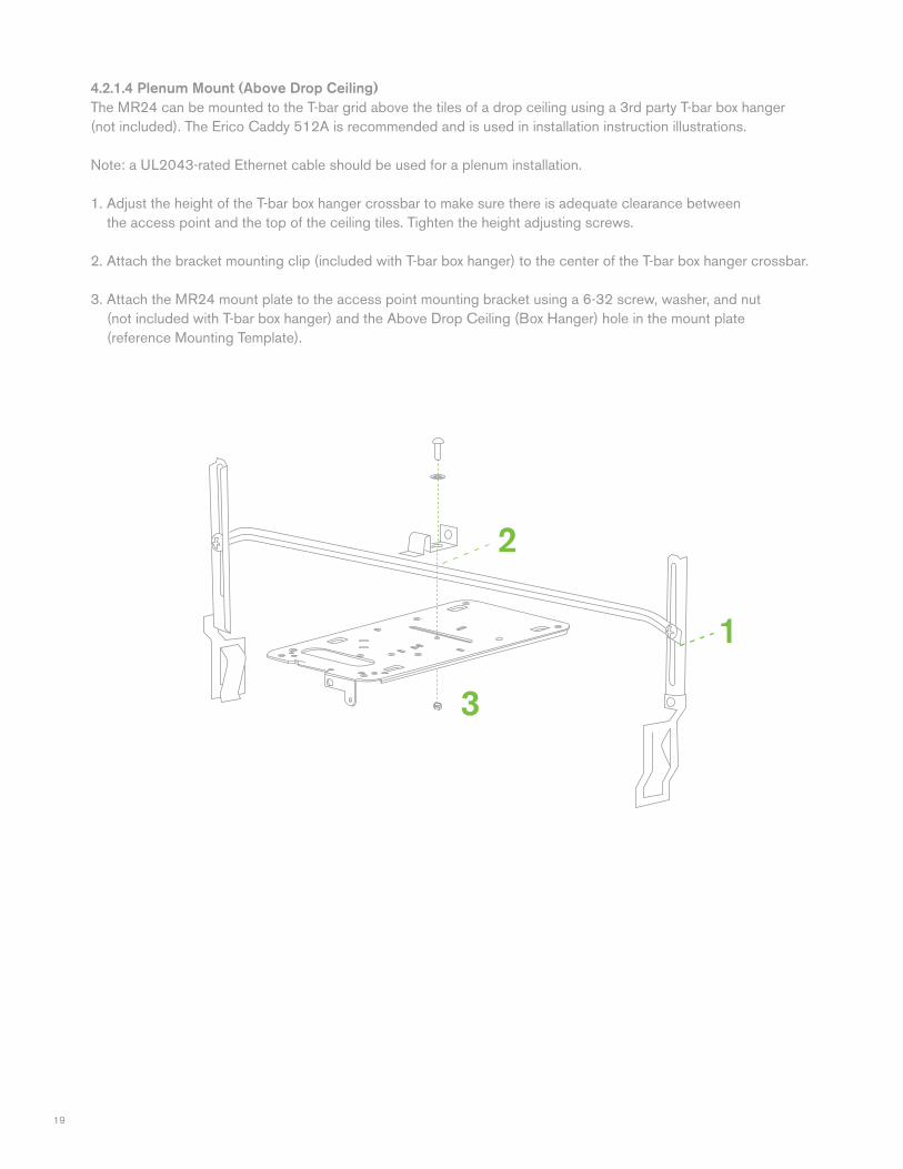
4.2.1.4 Plenum Mount (Above Drop Ceiling)The MR24 can be mounted to the T-bar grid above the tiles of a drop ceiling using a 3rd party T-bar box hanger (not included). The Erico Caddy 512A is recommended and is used in installation instruction illustrations.
Note: a UL2043-rated Ethernet cable should be used for a plenum installation.
1. Adjust the height of the T-bar box hanger crossbar to make sure there is adequate clearance between the access point and the top of the ceiling tiles. Tighten the height adjusting screws.
2. Attach the bracket mounting clip (included with T-bar box hanger) to the center of the T-bar box hanger crossbar.
3. Attach the MR24 mount plate to the access point mounting bracket using a 6-32 screw, washer, and nut (not included with T-bar box hanger) and the Above Drop Ceiling (Box Hanger) hole in the mount plate (reference Mounting Template).
2
1
3
20
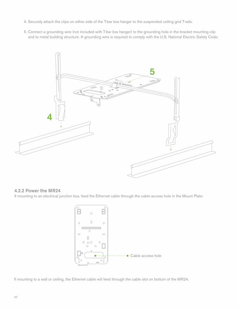
4.2.2 Power the MR24If mounting to an electrical junction box, feed the Ethernet cable through the cable access hole in the Mount Plate:
If mounting to a wall or ceiling, the Ethernet cable will feed through the cable slot on bottom of the MR24.
Cable access hole
4. Securely attach the clips on either side of the T-bar box hanger to the suspended ceiling grid T-rails.
5. Connect a grounding wire (not included with T-bar box hanger) to the grounding hole in the bracket mounting clip and to metal building structure. A grounding wire is required to comply with the U.S. National Electric Safety Code.
5
4
21
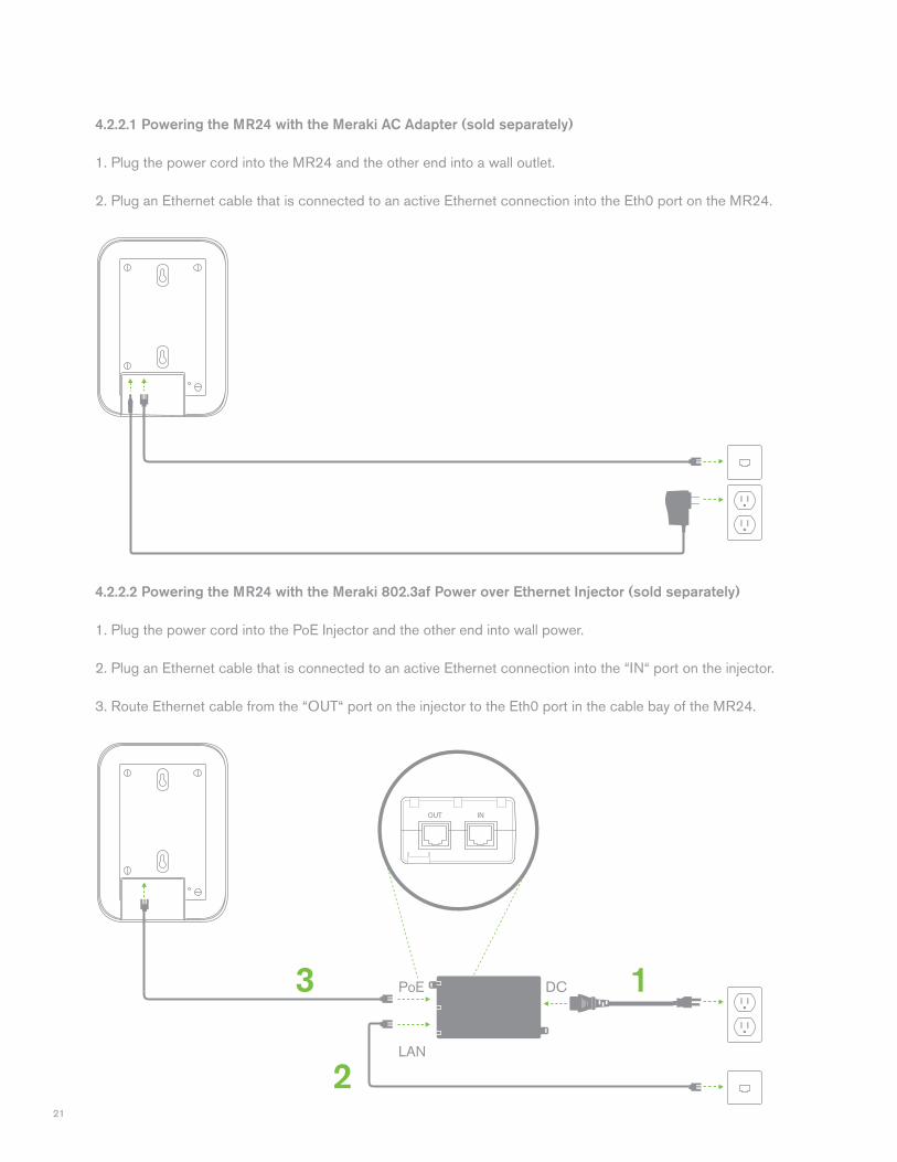
4.2.2.1 Powering the MR24 with the Meraki AC Adapter (sold separately)
1. Plug the power cord into the MR24 and the other end into a wall outlet. 2. Plug an Ethernet cable that is connected to an active Ethernet connection into the Eth0 port on the MR24.
4.2.2.2 Powering the MR24 with the Meraki 802.3af Power over Ethernet Injector (sold separately)
1. Plug the power cord into the PoE Injector and the other end into wall power. 2. Plug an Ethernet cable that is connected to an active Ethernet connection into the “IN“ port on the injector. 3. Route Ethernet cable from the “OUT“ port on the injector to the Eth0 port in the cable bay of the MR24.
1
2
3 DCPoE
LAN
22
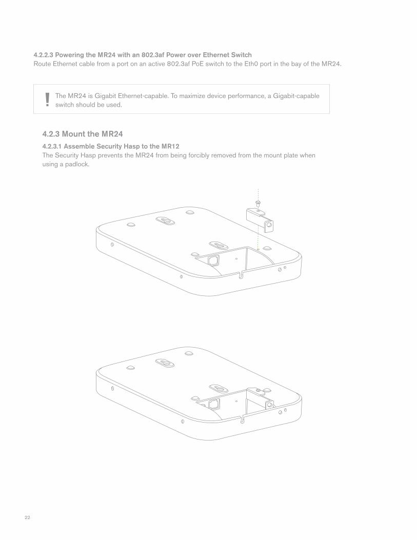
4.2.3 Mount the MR244.2.3.1 Assemble Security Hasp to the MR12The Security Hasp prevents the MR24 from being forcibly removed from the mount plate when using a padlock.
4.2.2.3 Powering the MR24 with an 802.3af Power over Ethernet Switch Route Ethernet cable from a port on an active 802.3af PoE switch to the Eth0 port in the bay of the MR24.
The MR24 is Gigabit Ethernet-capable. To maximize device performance, a Gigabit-capable switch should be used.
23
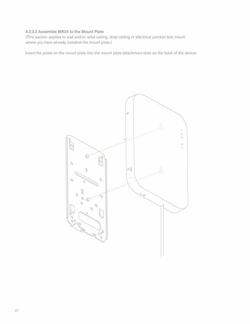
4.2.3.2 Assemble MR24 to the Mount Plate(This section applies to wall and/or solid ceiling, drop ceiling or electrical junction box mount where you have already installed the mount plate.)
Insert the posts on the mount plate into the mount plate attachment slots on the back of the device.
24
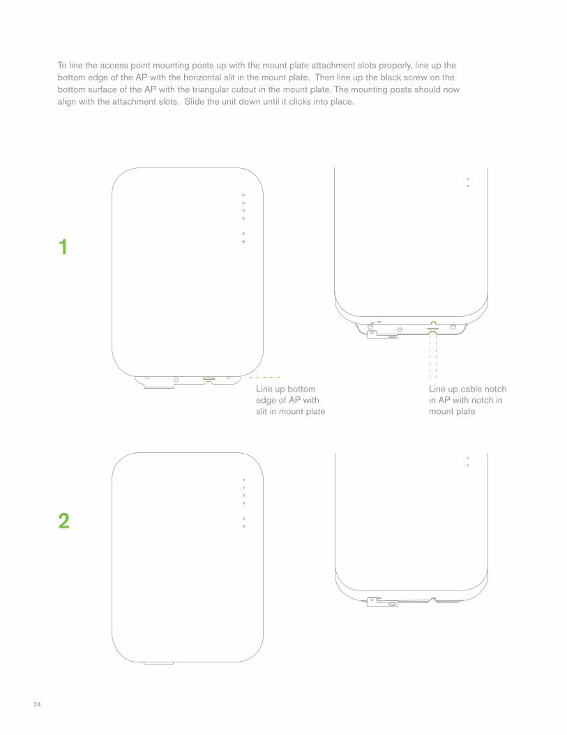
To line the access point mounting posts up with the mount plate attachment slots properly, line up the bottom edge of the AP with the horizontal slit in the mount plate. Then line up the black screw on the bottom surface of the AP with the triangular cutout in the mount plate. The mounting posts should now align with the attachment slots. Slide the unit down until it clicks into place.
2
1
Line up bottom edge of AP with slit in mount plate
Line up cable notch in AP with notch in mount plate
25
4.2.3.3 Desk or Shelf MountThe MR24 can be placed on a desk or shelf resting on the non-scratch rubber feet. The mount plate is not necessary for a desk or shelf mounting.
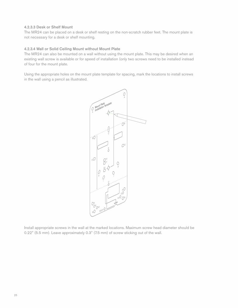
4.2.3.4 Wall or Solid Ceiling Mount without Mount PlateThe MR24 can also be mounted on a wall without using the mount plate. This may be desired when an existing wall screw is available or for speed of installation (only two screws need to be installed instead of four for the mount plate.
Using the appropriate holes on the mount plate template for spacing, mark the locations to install screws in the wall using a pencil as illustrated.
Install appropriate screws in the wall at the marked locations. Maximum screw head diameter should be 0.22” (5.5 mm). Leave approximately 0.3” (7.5 mm) of screw sticking out of the wall.
26
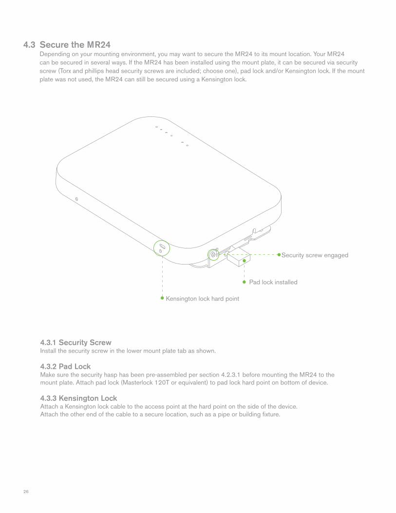
4.3 Secure the MR24 Depending on your mounting environment, you may want to secure the MR24 to its mount location. Your MR24 can be secured in several ways. If the MR24 has been installed using the mount plate, it can be secured via security screw (Torx and phillips head security screws are included; choose one), pad lock and/or Kensington lock. If the mount plate was not used, the MR24 can still be secured using a Kensington lock.
4.3.1 Security Screw Install the security screw in the lower mount plate tab as shown.
4.3.2 Pad LockMake sure the security hasp has been pre-assembled per section 4.2.3.1 before mounting the MR24 to the mount plate. Attach pad lock (Masterlock 120T or equivalent) to pad lock hard point on bottom of device.
4.3.3 Kensington LockAttach a Kensington lock cable to the access point at the hard point on the side of the device.Attach the other end of the cable to a secure location, such as a pipe or building fixture.
Pad lock installed
Kensington lock hard point
Security screw engaged
27
4.4 Verify Device Functionality and Test Network Coverage 1. Check LEDs The Radio Power LED should be solid green. If it is flashing orange, the firmware is automatically upgrading and the LED should turn green when the upgrade is completed (normally in under thirty minutes). If the device is a gateway, the Ethernet LED and the four Signal Strength LEDs should be green as well. If the device is a repeater only, the Ethernet LED will not be illuminated and the number of green Signal Strength LEDs will show the signal strength to the nearest Meraki device. See section 2.6 for further details about information conveyed by the LEDs. Note: Your MR24 must have an active route to the Internet to check and upgrade its firmware.
2. Verify access point connectivity Use any 802.11 client device to connect to the MR24 and verify proper connectivity using the client’s web browser.
3. Check network coverage Confirm that you have good signal strength throughout your coverage area. You can use the signal strength meter on a laptop, smart phone, or other wireless device.
5 Troubleshooting Reference the Meraki knowledge base at http://meraki.com/support/knowledge_base for additional information and troubleshooting tips.
28
6 Regulatory Information for MR24
U.S. Regulatory Wireless Notice Federal Communication Commission Interference Statement: This equipment has been tested and found to comply with the limits for a Class B digital device, pursuant to Part 15 of the FCC Rules. These limits are designed to provide reasonable protection against harmful interference in a residential installation. This equipment generates, uses and can radiate radio frequency energy and, if not installed and used in accordance with the instructions, may cause harmful interference to radio communications. However, there is no guarantee that interference will not occur in a particular installation. If this equipment does cause harmful interference to radio or television reception, which can be determined by turning the equipment off and on, the user is encouraged to try to correct the interference by one of the following measures: • Reorient or relocate the receiving antenna. • Increase the separation between the equipment and receiver. • Connect the equipment into an outlet on a circuit different from that to which the receiver is connected. • Consult the dealer or an experienced radio/TV technician for help. FCC Caution: Any changes or modifications not expressly approved by the party responsible for compliance could void the user’s authority to operate this equipment. This device complies with Part 15 of the FCC Rules. Operation is subject to the following two conditions: • this device may not cause harmful interference, and • this device must accept any interference received, including interference that may cause undesired operation.
FCC Radiation Exposure Statement: This equipment complies with FCC radiation exposure limits set forth for an uncontrolled environment. This equipment should be installed and operated with minimum distance 20 cm between the radiator and your body. This transmitter must not be co-located or operating in conjunction with any other antenna or transmitter. IEEE 802.11b or 802.11g operation of this product in the USA is firmware-limited to channels 1 through 11.
29
Canadian Regulatory Wireless Notice (Model Number: 600-14010) This device complies with RSS-210 of the Industry Canada Rules. Operation is subject to the following two conditions: • this device may not cause interference and • this device must accept any interference, including interference that may cause undesired operation of the device.
Ce dispositif est conforme à la norme CNR-210 d’Industrie Canada applicable aux appareils radio exempts de licence. Son fonctionnement est sujet aux deux conditions suivantes:
• le dispositif ne doit pas produire de brouillage préjudiciable, et • ce dispositif doit accepter tout brouillage reçu, y compris un brouillage susceptible de provoquer un fonctionnement indésirable.
Important Notice: (i) The device for operation in the band 5150-5250 MHz is only for indoor use to reduce the potential for harmful interference to co-channel mobile satellite systems; (ii) The maximum antenna gain permitted for devices in the bands 5250-5350 MHz and 5470-5725 MHz shall comply with the e.i.r.p. limit; and (iii) The maximum antenna gain permitted for devices in the band 5725-5825 MHz shall comply with the e.i.r.p. limits specified for point-to-point and non point-to-point operation as appropriate. (iv) High-power radars are allocated as primary users (i.e. priority users) of the bands 5250-5350 MHz and 5650-5850 MHz and that these radars could cause interference and/or damage to LE-LAN devices. Note Importante: (i) L’appareil dans la bande 5150-5250 MHz est seulement pour utilisation à l’intérieur d’un bâtiment pour réduire le ris que de brouillage apporté aux systèmes de satellite mobile; (ii) Le gain d’antenne maximal autorisé pour les appareils dans les bandes 5250-5350 MHz et 5470-5725 MHz doivent respecter la limite e.i.r.p. , et (iii) Le gain d’antenne maximal autorisé pour les appareils dans les bandes 5725-5825 MHz doivent respecter la limite e.i.r.p., ainsi que les limites pour les opérations point-à-point et non-point-à-point, le cas échéant; (iv) Les radars à haute puissance sont les usagers primaires (c’est-à-dire, des utilisateurs prioritaires) pour les bandes 5250-5350 MHz et 5650-5850 MHz et que ces radars pourraient provoquer des interférences et / ou des dommages aux appareil LE-LAN.
IC Radiation Exposure Statement: This equipment complies with IC radiation exposure limits set forth for an uncontrolled environment. This equipment should be installed and operated with minimum distance 20 cm between the radiator and your body.
NOTE IMPORTANTE: (Pour l’utilisation de dispositifs mobiles) Déclaration d’exposition aux radiations:
Cet équipement est conforme aux limites d’exposition aux rayonnements IC établies pour un environnement non contrôlé. Cet équipement doit être installé et utilisé avec un minimum de 20 cm de distance entre la source de rayonnement et votre corps.
30
Europe – EU Declaration of Conformity This device complies with the essential requirements of the R&TTE Directive 1999/5/EC. The following test methods have been applied in order to prove presumption of conformity with the essential requirements of the R&TTE Directive 1999/5/EC:
Radio: EN 300 328, EN 301 EMC: EN 301 489-1, EN 301 489-17 Safety: EN 60950-1 RF Exposure: EN 50385 Emissions: EN 55022 Immunity: EN 61000-4-2, EN 61000-4-3, EN 61000-4-4, EN 61000-4-5, EN 61000-4-6 This device is a 2.4 GHz and 5 GHz wideband transmission system (transceiver), intended for use in all EU member states and EFTA countries with the following restrictions:
In Italy the end-user should apply for a license at the national spectrum authorities in order to obtain authorization to use the device for setting up outdoor radio links and/or for supplying public access to telecommunications and/or network services.
The device may not be used in the 5 GHz spectrum unless the 5.725 - 5.875 GHz has been disabled. This can be done through the Meraki Dashboard.
In Italy the end-user should apply for a license at the national spectrum authorities in order to obtain authorization to use the device for setting up outdoor radio links and/or for supplying public access to telecommunications and/or network services.
Česky(Czech) Meraki,Inc.tímtoprohlašuje,žetentowirelessdevicejeveshoděsezákladnímipožadavky adalšímipříslušnýmiustanovenímisměrnice.
Dansk(Danish) UndertegnedeMeraki,Inc.erklærerherved,atfølgendeudstyrwirelessdeviceoverholder devæsentligekravogøvrigerelevantekravidirektiv1999/5/EF. Deutsch(German) HiermiterklärtMeraki,Inc.,dasssichdasGerätwirelessdeviceinÜbereinstimmungmit dengrundlegendenAnforderungenunddenübrigeneinschlägigenBestimmungender Richtlinie1999/5/EGbefindet. Eesti(Estonian) KäesolevagakinnitabMeraki,Inc.seadmewirelessdevicevastavustdirektiivi1999/5/EÜ põhinõuetelejanimetatuddirektiivisttulenevatele. English Hereby,Meraki,Inc.,declaresthatthiswirelessdeviceisincompliancewiththeessential requirementsandotherrelevantprovisionsofDirective1999/5/EC.
31
Español(Spanish) PormediodelapresenteMeraki,Inc.declaraqueelwirelessdevicecumpleconlosrequisitos esencialesycualesquieraotrasdisposicionesaplicablesoexigiblesdelaDirectiva1999/5/CE.
Ελληνική(Greek) ΜΕΤΗΝΠΑΡΟΥΣΑMeraki,Inc.ΔΗΛΩΝΕΙΟΤΙwirelessdeviceΣΥΜΜΟΡΦΩΝΕΤΑΙΠΡΟΣΤΙΣ ΟΥΣΙΩΔΕΙΣΑΠΑΙΤΗΣΕΙΣΚΑΙΤΙΣΛΟΙΠΕΣΣΧΕΤΙΚΕΣΔΙΑΤΑΞΕΙΣΤΗΣΟΔΗΓΙΑΣ1999/5/ЕΚ.
Français(French) ParlaprésenteMeraki,Inc.déclarequel’appareilwirelessdeviceestconformeauxexigences essentiellesetauxautresdispositionspertinentesdeladirective1999/5/CE.
Italiano(Italian) ConlapresenteMeraki,Inc.dichiarachequestowirelessdeviceèconformeairequisitiessenziali edallealtredisposizionipertinentistabilitedalladirettiva1999/5/CE.
Latviski(Latvian) AršoMeraki,Inc.deklarē,kawirelessdeviceatbilstDirektīvas1999/5/EKbūtiskajāmprasībām uncitiemartosaistītajiemnoteikumiem.
Lietuvių(Lithuanian) ŠiuoMeraki,Inc.deklaruoja,kadšiswirelessdeviceatitinkaesminiusreikalavimusirkitas 1999/5/EBDirektyvosnuostatas.
Nederland(Dutch) HierbijverklaartMeraki,Inc.dathettoestelwirelessdeviceinovereenstemmingismetde essentiëleeisenendeandererelevantebepalingenvanrichtlijn1999/5/EG.
Malti(Maltese) Hawnhekk,Meraki,Inc.,jiddikjaralidanwirelessdevicejikkonformamal-ħtigijietessenzjali umaprovvedimentioħrajnrelevantilihemmfid-Dirrettiva1999/5/EC.
Magyar(Hungarian) Alulírott,Meraki,Inc.nyilatkozom,hogyawirelessdeviccemegfelelavonatkozóalapvetõ követelményeknekésaz1999/5/ECirányelvegyébelõírásainak.
Polski(Polish) NiniejszymMeraki,Inc.oświadcza,żewirelessdevicejestzgodnyzzasadniczymiwymogami orazpozostalymistosownymi
Português(Portuguese) Meraki,Inc.declaraqueestewirelessdeviceestáconformecomosrequisitosessenciaise outrasdisposiçõesdaDirectiva1999/5/CE.
Slovensko(Slovenian) Meraki,Inc.izjavlja,dajetawirelessdevicevskladuzbistvenimizahtevamiinostalimi relevantnimidolocilidirektive1999/5/ES.
32
Slovensky(Slovak) Meraki,Inc.týmtovyhlasuje,žewirelessdevicesplnazákladnépožiadavkyavšetkypríslušné ustanoveniaSmernice1999/5/ES.
Suomi(Finnish) Meraki,Inc.vakuuttaatätenettäwirelessdevicetyyppinenlaiteondirektiivin1999/5/EY oleellistenvaatimustenjasitäkoskeviendirektiivinmuidenehtojenmukainen.
Svenska(Swedish) HärmedintygarMeraki,Inc.attdennawirelessdevicestårIöverensstämmelsemedde väsentligaegenskapskravochövrigarelevantabestämmelsersomframgårdirektiv1995/5/EG.

33
Copyright © 2011 Meraki, Inc. All rights reserved. Trademarks Meraki® is a registered trademark of Meraki, Inc.

34
www.meraki.com 660 Alabama St.San Francisco, California 94110Phone: +1 415 632 5900 Fax: +1 415 632 5890

© Meraki, Inc. 2011 280-14030