merlin legend communications system release 7 · 5ess, audix, conversant, centrevu, definity, magic...
TRANSCRIPT

555-670-111Comcode 108370271
Issue 1April 1999
MERLIN LEGEND®
Communications SystemRelease 7.0
System Programmming
Disclaimer
Intellectual property related to this product (including trademarks) and registered to LucentTechnologies Inc. has been transferred or licensed to Avaya Inc.
Any reference within the text to Lucent Technologies Inc. or Lucent should be interpreted as references to Avaya Inc. The exception is cross references to books published prior to April 1, 2001, which may retain their original Lucent titles.
Avaya Inc. formed as a result of Lucent’s planned restructuring, designs builds and deliversvoice, converged voice and data, customer relationship management, messaging, multi-servicenetworking and structured cabling products and services. Avaya Labs is the research and development arm for the company.
Copyright © 2000, Avaya Inc.All Rights ReservedPrinted in U.S.A.

������
Every effort has been made to ensure that the information in this guide is complete and accurate at the time of printing. Information, however, is subject to change. See Appendix A, “Customer Support Information,” in System Programming for important information.
������ ������������������������������
Toll fraud is the unauthorized use of your telecommunications system by an unauthorized party—for example, persons other than your company’s employees, agents, subcontractors, or persons working on your company’s behalf. Note that there may be a risk of toll fraud associated with your telecommunications system, and, if toll fraud occurs, it can result in substantial additional charges for your telecommunications services.
You and your system manager are responsible for the security of your system, such as programming and configuring your equipment to prevent unauthorized use. The system manager is also responsible for reading all installation, instruction, and system administration documents provided with this product in order to fully understand the features that can introduce risk of toll fraud and the steps that can be taken to reduce that risk. Lucent Technologies does not warrant that this product is immune from or will prevent unauthorized use of common-carrier telecommunication services or facilities accessed through or connected to it. Lucent Technologies will not be responsible for any charges that result from such unauthorized use. For important information regarding your system and toll fraud, see Appendix A, “Customer Support Information,” in System Programming.
���������������������������������������
This equipment has been tested and found to comply with the limits for a Class A digital device, pursuant to Part 15 of the FCC Rules. These limits are designed to provide reasonable protection against harmful interference when the equipment is operated in a commercial environment. This equipment generates, uses, and can radiate radio frequency energy and, if not installed and used in accordance with the instruction manual, may cause harmful interference to radio communications. Operation of this equipment in a residential area is likely to cause harmful interference, in which case the user will be required to correct the interference at their own expense. For further FCC information, see Appendix A, “Customer Support Information,” in System Programming.
���������� �����������������������������������������������
This digital apparatus does not exceed the Class A limits for radio noise emissions set out in the radio interferenceregulations of the Canadian Department of Communications.
Le Présent Appareil Numérique n’émet pas de bruits radioélectriques dépassant les limites applicables auxappareils numériques de la classe A préscrites dans le réglement sur le brouillage radioélectrique édicté par leministère des Communications du Canada.
���� ��� ������
The MERLIN LEGEND Communications System is certified to be Year 2000 compliant. Additional information on this certification, and other issues regarding Year 2000 compliance, is available online at http://www.lucent.com/enterprise/sig/yr2000.
!�����"�
5ESS, AUDIX, CONVERSANT, CentreVu, DEFINITY, Magic On Hold, MERLIN, MERLIN LEGEND, MERLIN Mail, PARTNER, PassageWay, MLX-10, MLX-10D, MLX-10DP, MLX-16DP, MLX-20L, MLX-28D, MLS-6, MLS-12, MLS-12D, MLS-18D, MLS-34D, SYSTIMAX, TransTalk, and Voice Power are registered trademarks and 4ESS, Intuity, Lucent Technologies, and Prologix are trademarks of Lucent Technologies in the US and other countries.
Acculink, ACCUNET, MEGACOM, MulitiQuest, MLX-5, MLX-5D, and NetPROTECT are registered trademarks of AT&T.
Microsoft, Windows, Windows NT, and MS-DOS are registered trademarks of Microsoft Corporation.
ProComm and ProComm Plus are registered trademarks of DataStorm Technologies, Inc.
Supra, Supra NC, StarSet, and Mirage are registered trademarks of Plantronics, Inc.
UNIX is a registered trademark of UNIX System Laboratories, Inc.
PagePac is a registered trademark and Powermate and Zonemate are trademarks of DRACON, a division of Harris Corporation.
Okidata is a registered trademark of Okidata Corporation.
Pipeline is a trademark of Ascend Communications, Inc.
Intel and Pentium are registered trademarks of Intel Corporation.
Apple and Macintosh are registered trademarks of Apple Computer, Inc.
IBM is a registered trademark of International Business Machines, Inc.
Novell and NetWare are registered trademarks of Novell Corporation.
CLASS is a servicemark of Bellcore.
�� ��#$�%&'''()�����!��$����#��� ��������***+,- +&&&
.����#$������/�� �������& 01- �-&
2�������3�. �����&
. ��&'''

�����#����������
For more information about Lucent Technologies documents, refer to the section entitled “Related Documents” in “About This Guide” in System Programming.
�� ��!��� $��������
In the continental US, Lucent Technologies provides a toll-free customer helpline 24 hours a day. Call the Lucent Technologies Helpline at 1-800-628-2888 or your Lucent Technologies authorized dealer if you need assistance when installing, programming, or using your system. Outside the continental US, contact your local Lucent Technologies authorized representative.
���4�"5�#������#6��
For assistance in designing a private network, call the Network Engineering Group at 1-888-297-4700.
)�����!��$����#����� �����������
Whether or not immediate support is required, all toll fraud incidents involving Lucent Technologies products or services should be reported to Lucent Technologies Corporate Security at 1-800-821-8235. In addition to recording the incident, Lucent Technologies Corporate Security is available for consultation on security issues, investigation support, referral to law enforcement agencies, and educational programs.
)�����!��$����#�����������/������
If you suspect you are being victimized by toll fraud and you need technical support or assistance, call BCS National Service Assistance Center at 1-800-628-2888.
7�����
Lucent Technologies provides a limited warranty on this product. Refer to “Limited Warranty and Limitation of Liability” in Appendix A, “Customer Support Information,” of System Programming.
Call: BCS Publications Center
Voice 1-800-457-1235 International Voice 317-322-6791
Fax 1-800-457-1764 International Fax 317-322-6699
Write: BCS Publications Center
2855 North Franklin Road
Indianapolis, IN 46219-1385
Order: Document No. 555-670-111
Comcode: 108370271
Issue 1, April 1999

Master TOC i
System ProgrammingMaster Table of Contents
New Features and Enhancements� Release 7.0 Enhancements
(April 1999) xxvii
MLS and Enhanced Tip/Ring (ETR) TelephoneSupport xxvii
Expanded Digital Endpoint Connectivity xxviii
Voice Announce on Idle Only Option on MLX Telephones xxviii
Priority Call Queuing xxix
Calling Party Name on Caller ID xxix
MLX Headset Operation xxx
Touch-Tone or Rotary Signaling xxx
Abandoned Call Information Reported toMERLIN LEGEND Reporter xxx
Prior Releases: Features and Enhancements� Release 6.1 Enhancements
(August 1998) xxxi
Private Networking xxxi
Service Observing xxxiv
WinSPM xxxiv
Windows NT Driver xxxv
� Release 6.0 Enhancements (February 1998) xxxv
Private Networks xxxv
Group Calling Enhancements xxxvii
Centrex Transfer via Remote Call Forwarding xxxviii
Authorization Codes andRemote Call Forwarding xxxix
� Release 5.0 Enhancements (June 1997) xxxix
Computer Telephony Integration (CTI) xxxix
HotLine Feature xli
System Programming
ii Master TOC
Group Calling Enhancements xlii
MLX-5 and MLX-5D Telephones xliv
� Release 4.2 Enhancements (June 1997) xliv
Additional Network Switch and Services Optionsfor ISDN Primary Rate Interface (PRI) xliv
Improvements to Station Message DetailRecording (SMDR) and Support for MERLIN LEGEND Reporter Application xlv
MERLIN LEGEND Reporter xlvi
Maintenance Enhancements xlvi
� Release 4.1 Enhancements(June 1997) xlvii
Coverage Timers Programmed forIndividual Extensions xlvii
Night Service with Coverage Control xlvii
Night Service Group Line Assignment xlviii
Forward on Busy xlviii
Maintenance Testing for BRI Facilities that ArePart of Multiline Hunt Groups (MLHGs) xlviii
� Release 4.0 Enhancements (March 1996) xlix
Support for Up to 200 Extensions xlix
Support for National ISDN BRI Service xlix
New Control Unit Modules xlix
Support for 2B Data Applications l
Support for T1 Switched 56Digital Data Transmission l
Forwarding Delay Option l
Voice Announce on Queued Call Console li
Time-Based Option forOverflow on Calling Group li
Single-Line Telephone Enhancements li
Seven-Digit Password for SPM li
Master TOC iii
Master Table of Contents
� Release 3.1 Enhancements (March 1996) lii
Call Restriction Checking for Star Codes lii
Trunk-to-Trunk Transfer Set for Each Extension lii
Programmable Second Dial Tone Timer lii
Security Enhancements lii
� Release 3.0 Enhancements (August 1994) liv
Equipment liv
Installation, Upgrade Administration, and Maintenance lv
User Features lv
Additional Application Packages, Adjuncts, andAdapter Enhancements lvii
� Release 2.1 Enhancements (August 1994) lviii
Operational lviii
Installation and Hardware lix
Equipment and Operations lx
Additional Application Packages, Telephones,Adjuncts, and Adapter lx
� Release 2.0 Enhancements (October 1992) lxi
Programming lxi
Operational lxii
Fax Attendant System™ lxiii
408 GS/LS-MLX Module lxiii
Primary Rate Interface (PRI) lxiii
Maintenance lxiv
� Release 1.1 Enhancements (October 1992) lxiv
Language Selection lxiv
Programming and Maintenance lxv
Operational lxv
SPM lxv
Equipment lxv
PF Registration lxv

System Programming
iv Master TOC
About This Guide� Intended Audience lxvii
� How to Use This Guide lxvii
� Terms and Conventions Used lxviii
Typographical Conventions lxix
Product Safety Advisories lxx
� Security lxx
� Related Documents lxxi
� How to Comment on This Guide lxxii
1 Programming Basics
� Overview 1-1
� Introduction to System Programming 1-2
Planning Forms 1-2
Types of Programming 1-3
� System Programming Console 1-4
Console Components 1-5
Console Buttons 1-6
Console Overlay 1-8
Console and DSS Lights 1-9
� Programming Procedures 1-10
Procedure Organization 1-10
Procedure Contents 1-10
Programming Screens 1-11
Verifying Data Entry 1-13
Saving Entries and Moving among Screens 1-14
Using Enter 1-16
Using Next 1-16
System Programming Hierarchy 1-17
Master TOC v
Master Table of Contents
� Access to System Programmingfrom the MLX-20L Console 1-43
System Programming Menu 1-44
� Idle States 1-45
System Forced Idle 1-46
Line or Trunk Idle 1-47
Extension Forced Idle 1-47
100D Module Idle 1-48
Forced Idle Reminder Tones 1-48
2 Programming with SPM
� Overview 2-1
� System Requirements 2-2
� Installing the SPM Software 2-4
DOS Installation 2-4
DOS Installation with Windows 95 2-6
Initializing the SPM Software 2-10
� Connecting the PC 2-13
Direct Local Connection 2-13
Local Modem Connection 2-15
Remote Modem Connection 2-15
� Accessing SPM 2-16
Direct Local Connection 2-16
Local or Remote Modem Connection 2-18
� Using SPM 2-20
SPM Screens 2-21
SPM Main Menu Options 2-25
SPM Help 2-26
Backup 2-26
Boards 2-30
Browse 2-34
Convert 2-35
System Programming
vi Master TOC
Language 2-41
Maintenance 2-42
Pass-Thru 2-43
Password 2-46
Print Options 2-47
Restore 2-48
� System Programming 2-51
Basic Programming Information 2-52
Idle States 2-52
Accessing System Programming 2-55
Printing Reports 2-55
� Upgrading the System 2-57
Before You Begin 2-58
Upgrade Procedure 2-59
� Surrogate Mode Programming 2-73
3 Programming Procedures
� Overview 3-1
� Basic System Operating Conditions 3-2
System Restart 3-2
System Programming Position Assignment 3-3
System Language 3-4
Board Renumbering 3-5
Mode of Operation 3-5
Automatic Maintenance Busy 3-6
Set System Date 3-8
Set System Time 3-9
� System Renumbering 3-10
Select System Numbering Plan 3-13
Single Renumbering 3-14
Master TOC vii
Master Table of Contents
Block Renumbering 3-15
Non-Local Dial Plan Extension Ranges 3-16
Direct Station Selector (DSS) Page Buttons 3-20
� System Operator Positions 3-21
Primary Operator Positions 3-22
QCC System Operator Positions 3-22
DLC Operator Positions 3-24
� Lines and Trunks 3-25
Type of Trunk 3-26
Outmode Signaling for Loop- or Ground-Start Trunks 3-27
Rotary Trunk Digit Transfer 3-28
Ringing Frequency 3-28
Second Dial Tone Timer 3-29
Disconnect Signaling Reliability 3-30
Toll Type 3-31
Hold Disconnect Interval 3-32
Principal User for Personal Line 3-33
QCC Queue Priority Level 3-34
QCC Operator to Receive Calls 3-35
Loop-Start Identification Delay 3-36
Clock Synchronization 3-37
Trunks to Pools Assignment 3-38
Copy Options for Lines/Trunks 3-40
� Uniform Dial Plan Facilities 3-42
Switch Identifiers 3-42
� DS1 Facilities 3-45
Type of DS1 Facility 3-45
Switched 56 Dial Plan Routing 3-50
Frame Format 3-51
Zero Code Suppression 3-51
Signaling Mode 3-52
Line Compensation 3-53
Channel Service Unit 3-54

System Programming
viii Master TOC
� Tie Trunks 3-54
Direction 3-55
Tie Trunk Seizure Type 3-55
E&M Signal 3-56
Dial Mode 3-57
Tie Trunk Dial Tone 3-58
Tie Trunk Answer Supervision Time 3-59
Disconnect Time 3-60
� DID Trunks 3-61
Block Assignment 3-61
DID Trunk Type 3-62
Disconnect Time 3-63
Expected Digits 3-63
Delete Digits 3-64
Add Digits 3-65
Signaling 3-65
Invalid Destination 3-66
� PRI Facilities 3-67
Switch Type 3-68
Telephone Number 3-69
B-Channel Groups 3-70
Network Service 3-72
Copy Telephone Number to Send 3-73
Incoming Routing 3-74
Telephone Number to Send 3-75
Test Telephone Number 3-76
Timers and Counters 3-77
Terminal Equipment Identifier 3-79
Dial Plan Routing 3-80
Outgoing Tables 3-83
Network Selection Tables 3-83
Special Services Tables 3-84
Master TOC ix
Master Table of Contents
Call-by-Call Service Table 3-86
� BRI Facilities 3-88
Service Profile Identifier (SPID) andDirectory Number (DN) 3-89
Timers 3-90
� Extensions 3-92
Assign Trunks or Pools to Extensions 3-92
Copy Line/Trunk Assignments 3-95
Assign Intercom or System Access Buttons 3-97
Analog Multiline Telephone without Built-inSpeakerphone (BIS) or Hands-Free Answer onIntercom (HFAI) Capability 3-101
Analog Multiline Telephones with VoiceAnnounce Feature 3-102
Rotary Signaling on Tip/Ring Ports 3-103
Tip/Ring Functionality on 412 LS-ID ETR and016 ETR Modules 3-104
� Auxiliary Equipment 3-106
Music-On-Hold 3-106
Loudspeaker Paging 3-107
Fax Machines 3-108
Maintenance Alarms 3-110
Voice Messaging System and Automated Attendant 3-110
� Computer Telephony Integration (CTI) Link 3-112
Programming a CTI Link 3-112
Summary: CTI Link 3-114
CTI Link Programming Errors 3-115
� Optional Extension Features 3-118
Extension Language 3-118
Pool Dial-Out Code 3-119
Calling Restrictions 3-120
Copy Calling Restrictions 3-122
ARS Restriction Level for Extensions 3-123
Forced Account Code Entry 3-124
Microphone Operation 3-125

System Programming
x Master TOC
Authorization Codes 3-126
Remote Call Forwarding 3-127
Delayed Call Forwarding 3-128
Trunk-to-Trunk Transfer 3-129
Primary Cover Ring Delay 3-130
Secondary Cover Ring Delay 3-131
Group Coverage Ring Delay 3-132
HotLine 3-133
Display Preference 3-133
Service Observing 3-134
� Optional Operator Features 3-135
Operator Hold Timer 3-136
DLC Operator Automatic Hold 3-136
� QCC Optional Features 3-137
Hold Return 3-137
Automatic Hold or Release 3-138
Queue over Threshold 3-139
Elevate Priority 3-140
Calls-In-Queue Alert 3-140
QCC Operator to Receive Call Types 3-141
Call Type Queue Priority Level 3-143
Message Center Operation 3-144
Extended (Directed) Call Completion 3-145
Return Ring 3-146
Position Busy Backup 3-146
Voice Announce 3-147
� Optional Group Features 3-148
Pickup Groups 3-148
Group Paging 3-149
Group Coverage Member Assignments 3-150
Group Coverage Delay Interval 3-151
Group Calling Member Assignments 3-152
Master TOC xi
Master Table of Contents
Group Calling Line/Trunk or Pool Assignments 3-153
Priority Call Queuing 3-154
� Optional Group Calling Features 3-155
Hunt Type 3-155
Group Calling Delay Announcements 3-156
Group Calling Announcement Interval 3-157
Group Calling Repeat Announcement 3-158
Group Coverage Receiver 3-159
Group Calling Overflow and Thresholds 3-159
Group Calling Message-Waiting Indicator 3-161
Group Calling Calls-In-Queue Alarm Thresholds 3-162
Group Calling External Alert for Calls-In-Queue Alarm 3-163
Group Type 3-163
Queue Control 3-165
� System Features 3-167
Transfer Return Time 3-168
One-Touch Transfer/One-Touch Hold 3-168
Transfer Audible 3-170
Type of Transfer 3-171
Camp-On Return Time 3-171
Call Park Return Time 3-172
Delay Ring Interval 3-172
Automatic Callback Interval 3-173
Extension Status 3-174
SMDR Language 3-174
SMDR Call Report Format 3-175
SMDR Call Length 3-176
SMDR Calls Recorded on Call Report 3-176
SMDR Account Code Format 3-177
SMDR Talk Time 3-178
SMDR UDP Calls Recorded on Call Report 3-178
Inside Dial Tone 3-179
Reminder Service Cancel 3-180
Redirect Outside Calls to Unassigned Extension Numbers 3-180

System Programming
xii Master TOC
Host System Dial Codes for Behind Switch Mode 3-181
Recall Timer 3-182
Interdigit Timers 3-183
Allowed Lists 3-183
Assign Allowed Lists to Extensions 3-184
Disallowed Lists 3-185
Assign Disallowed Lists to Extensions 3-186
� Remote Access Features 3-186
Remote Access over Networked Tandem PRIand Tie Trunks 3-188
Remote Access Trunk Assignment 3-189
Remote Access Automatic Callback 3-190
Remote Access without Barrier Codes 3-191
Remote Access Barrier Codes 3-193
Remote Access with Barrier Codes 3-195
� Automatic Route Selection 3-197
ARS over Private Networked Tandem PRI and Tie Trunks 3-197
1 + 7-Digit Dialing Requirements 3-199
ARS Tables 3-199
Start and Stop Times for Subpatterns 3-200
Pool Routing 3-201
Facility Restriction Level 3-203
Digit Absorption 3-204
Other Digits 3-205
N11 Special Numbers Tables 3-206
Dial 0 Table 3-207
Voice and/or Data Routing 3-208
� Uniform Dial Plan Routing 3-208
UDP Pool Routing 3-209
UDP Facility Restriction Level 3-210
UDP Digit Absorption 3-211
UDP Other Digits 3-212
Master TOC xiii
Master Table of Contents
UDP Voice and/or Data Routing 3-213
� Night Service 3-214
Night Service Group Assignment 3-214
Night Service with Outward Restriction 3-216
Night Service with Time Set 3-217
Night Service with Coverage Control 3-218
� Labeling 3-219
Extension Directory 3-220
Lines or Trunks 3-221
Posted Message 3-221
Group Calling 3-222
System Speed Dial Directory 3-223
� Print Reports 3-224
Report Language 3-224
Printing System Reports 3-224
� Data Features 3-228
Analog Multiline Telephones at Data Workstations 3-229
2B Data 3-230
� Memory Card 3-231
Card Types 3-231
Inserting the Card 3-233
Memory Card Formatting 3-234
Backup 3-236
Automatic Backup 3-237
Backup Messages 3-239
Restore 3-241
Restore Messages 3-242
4 Centralized Telephone Programming
� Overview 4-1
� Introduction 4-2
� Access to Centralized Telephone Programming 4-3

System Programming
xiv Master TOC
� Program Extension 4-4
Programming Codes 4-6
Using the List Feature Menu 4-11
� Copy Extension 4-12
Features That Can Be Copied 4-12
� Feature Quick Reference 4-17
Account Code Entry 4-17
Alarm 4-18
Authorization Code 4-18
Auto Answer All 4-18
Auto Answer Intercom 4-19
Auto Dial 4-19
Automatic Line Selection 4-19
Barge-In 4-20
Callback 4-20
Caller Number and Name on Caller ID 4-21
Call Waiting 4-22
Camp-On 4-22
Conference 4-23
Coverage 4-23
Data Status 4-24
Direct Voice Mail 4-25
Do Not Disturb 4-25
Drop 4-25
Extension Status 4-26
Feature Button 4-27
Forward 4-27
Group Calling 4-27
Calling Group Supervisor 4-28
Group Page Auto Dial Button 4-28
Headset 4-29
Last Number Dial 4-30

Master TOC xv
Master Table of Contents
Messaging 4-30
Night Service 4-32
Notify 4-33
Park 4-33
Park Zone Auto Dial 4-34
Personal Speed Dial 4-34
Pickup 4-34
Privacy 4-35
Recall 4-35
Reminder Service 4-36
Ringing/Idle Line Preference 4-36
Ringing Options 4-37
Saved Number Dial 4-38
Send/Remove Message 4-39
Service Observing 4-39
Signaling 4-40
System Access/Intercom Buttons 4-40
System Speed Dial 4-41
Transfer 4-42
Voice Announce 4-42
A Customer Support Information
� Support Telephone Number A-1
� Federal Communications Commission (FCC) ElectromagneticInterference Information A-1
� Canadian Department of Communications (DOC)Interference Information A-2
� FCC Notification and Repair Information A-2
� Installation and Operational Procedures A-4
� DOC Notification and Repair Information A-5
� Renseignements sur la Notification duMinistère des Communications du Canada et la Réparation A-6
� Security of Your System: Preventing Toll Fraud A-8

System Programming
xvi Master TOC
� Toll Fraud Prevention A-10
Physical Security, Social Engineering, andGeneral Security Measures A-10
Security Risks Associated with Transferringthrough Voice Messaging Systems A-12
Security Risks Associated with the AutomatedAttendant Feature of Voice Messaging Systems A-14
Security Risks Associated with the RemoteAccess Feature A-15
� Other Security Hints A-16
Educating Users A-16
Educating Operators A-17
Detecting Toll Fraud A-17
Establishing a Policy A-18
Choosing Passwords A-19
Physical Security A-19
Limiting Outcalling A-19
� Limited Warranty and Limitation of Liability A-20
Limitation of Liability A-21
� Remote Administration and Maintenance A-21
B Menu Hierarchy
� Overview B-1
C LED Displays
� Overview C-1

Master TOC xvii
Master Table of Contents
D General Feature Use and Telephone Programming
� General Feature Use Information D-1
Fixed Features D-1
Programmed Buttons D-2
Feature Codes D-3
� Telephone and Operator Features D-3
� Telephone Programming D-28
Programming Methods D-28
E Button Diagrams
� Overview E-1
F Sample Reports
� Overview F-1
� System Information Report F-7
� Dial Plan Report F-9
� Label Information Report F-12
� Tie Trunk Information Report F-13
� DID Trunk Information Report F-14
� GS/LS Trunk Information Report F-15
� General Trunk Information Report F-16
� Switch 56 Data Information Report F-17
� DS1 Information Report F-18
� PRI Information Report F-19
� Remote Access (DISA) Information Report F-22
� Operator Information Report F-23
� Allowed Lists Report F-25
� Access to Allowed Lists Report F-26
� Disallowed Lists Report F-27
System Programming
xviii Master TOC
� Access to Disallowed Lists Report F-28
� Automatic Route Selection Report F-29
� Extension Directory Report F-30
� System Directory Report F-31
� Group Paging Report F-32
� Extension Information Report F-33
� Group Coverage Information Report F-35
� Direct Group Calling Information Report F-36
� Night Service Information Report F-37
� Group Call Pickup Report F-38
� Error Log Report F-39
� Authorization Code Information Report F-40
� BRI Information Report F-41
� Non-Local Dial Plan Report F-42
� Service Observing Information Report F-43
G General System Programming Sequence
� Basic System Operating Conditions G-1
� System Renumbering G-2
� Identify System Operator Positions G-2
� Lines and Trunks G-2
� Complex Lines G-3
� Telephones G-3
� Auxiliary Equipment G-4
� Print Reports G-4

Master TOC xix
Master Table of Contents
H Programming Special Characters
� Single-Line Telephones H-1
� Analog Multiline Telephones H-2
� MLX-10 and MLX-5 Nondisplay Telephones H-3
� MLX Display Telephones H-4
Glossary
Index

System Programming
xx Master TOC
Master LOF xxi
������������ ��������� ������ ����
� ����� ������ ��1-1 MLX-20L Telephone with Direct Station Selector (DSS) 1-41-2 Display Buttons and Main Menu 1-71-3 Console Overlay 1-81-4 Selecting a Block of Lines/Trunks 1-91-5 Information Screen 1-111-6 Menu Selection Screen 1-121-7 Data Entry Screen 1-121-8 Inspect Example 1-131-9 Sample Inspect Screen 1-141-10 Screen Keys 1-151-11 System Programming Menu Screens 1-441-12 System Busy Screen 1-46
� ����� ���� ������2-1 Direct Local Connection 2-142-2 Direct Local Connection, PC More Than 50 Feet Away 2-142-3 Local Modem Connection 2-152-4 Remote Modem Connection 2-162-5 SPM Display 2-222-6 SPM Help 2-262-7 Pass-Thru 2-43
� ����� ����������3-1 2-Digit Numbering 3-113-2 3-Digit Numbering 3-123-3 Set-Up-Space Numbering 3-123-4 PCMCIA Memory Card 3-2323-5 Inserting the Memory Card 3-233
� ������� �����E-1 MLX-20L and MLX-28D Telephone (Hybrid/PBX Mode) E-1E-2 MLX-16DP Telephone (Hybrid/PBX Mode) E-2E-3 MLX 5- and 10-Button Telephone (Hybrid/PBX Mode) E-2E-4 Analog Multiline Telephone (Hybrid/PBX Mode) E-3E-5 MLX-20L and MLX-28D Telephone (Key and Behind Switch Modes) E-4E-6 MLX-16DP Telephone (Key and Behind Switch Modes) E-4E-7 MLX 5- and 10-Button Telephone (Key and Behind Switch Modes) E-5E-8 Analog Multiline Telephone (Key and Behind Switch Modes) E-5E-9 ETR-34D Telephone (Hybrid/PBX Mode) E-6

Master LOF xxii
System Programming
E-10 ETR-18/18D Telephone (Hybrid/PBX Mode) E-6E-11 ETR-6 Telephone (Hybrid/PBX Mode) E-7E-12 MLS-34D Telephone (Hybrid/PBX Mode) E-7E-13 MLS-18D Telephone (Hybrid/PBX Mode) E-8E-14 MLS-12/12D Telephone (Hybrid/PBX Mode) E-8E-15 MLS-6 Telephone (Hybrid/PBX Mode) E-8E-16 ETR-34D Telephone (Key Mode) E-9E-17 ETR-18/18D Telephone (Key Mode) E-9E-18 ETR-6 Telephone (Key Mode) E-10E-19 MLS-34D Telephone (Key Mode) E-10E-20 MLS-18D Telephone (Key Mode) E-11E-21 MLS-12/12D Telephone (Key Mode) E-11E-22 MLS-6 Telephone (Key Mode) E-11E-23 ETR-34D Telephone (Behind Switch Mode) E-12E-24 ETR-18/18D Telephone (Behind Switch Mode) E-12E-25 ETR-6 Telephone (Behind Switch Mode) E-13E-26 MLS-34D Telephone (Behind Switch Mode) E-13E-27 MLS-18D Telephone (Behind Switch Mode) E-13E-28 MLS-12/12D Telephone (Behind Switch Mode) E-14E-29 MLS-6 Telephone (Behind Switch Mode) E-14

Master LOT xxiii
System ProgrammingMaster List of Tables
1 Programming Basics1-1 MLX-20L Console Components 1-51-2 Direct Station Selector (DSS) Components 1-61-3 Fixed Display Buttons 1-71-4 Screen Keys 1-151-5 System Programming Menu Options 1-441-6 Exiting System Programming 1-45
2 Programming with SPM2-1 SPM Configuration File (ams.cfg) Options 2-102-2 Function of PC Keys in SPM 2-232-3 SPM Main Menu Options 2-252-4 Backup Header: Release Number 2-272-5 Board Types 2-312-6 Programming Needed after Upgrade to Release 1.1 2-612-7 Programming Needed after Upgrade to Release 2.0 or 2.1 2-622-8 Programming Needed after Upgrade to Release 3.0 2-632-9 Programming Needed after Upgrade to Release 3.1 2-632-10 Programming Needed after Upgrade to Release 4.0 2-642-11 Programming Needed after Upgrade to Release 4.1 2-652-12 Programming Needed after Upgrade to Release 4.2 2-672-13 Programming Needed after Upgrade to Release 5.0 2-692-14 Programming Needed after Upgrade to Release 6.0 2-702-15 Programming Needed after Upgrade to Release 6.1 2-722-16 Optional Programming after Upgrade to Release 7.0 2-73
3 Programming Procedures3-1 Maximum Number of Operator Positions 3-223-2 Switched 56 Data Signaling Options 3-493-3 Timers and Counters 3-793-4 Special Services Table 3-863-5 Timers 3-913-6 Programming Codes for Assigning Buttons 3-1013-7 Other Data Programming Procedures 3-2283-8 Memory Card Formatting Messages 3-235
4 Centralized Telephone Programming4-1 Telephone Programming Codes 4-64-2 Features that Can Be Copied: All Telephones 4-134-3 Features That Can Be Copied: Direct-Line Consoles Only 4-15

Master LOT xxiv
System Programming
C LED DisplaysC-1 Line or Trunk Status for MLX-20L Console C-2C-2 Telephone Feature Status for DSS Console Only C-4
D General Feature Use and Telephone ProgrammingD-1 Telephone and Operator Features for MLX Telephones D-4D-2 Telephone and Operator Features for Analog Multiline and
Single-Line Telephones D-14D-3 Telephone and Operator Features for ETR and MLS Telephones D-21D-4 Programming Analog Multiline Telephones D-29D-5 Programming ETR and MLS Telephones D-30D-6 Programming MLX-10 and MLX-5 Nondisplay Telephones D-31D-7 Programming MLX Telephones by Using the Display D-32D-8 Programming TransTalk MDC 9000 and MDW Telephones D-34
F Sample ReportsF-1 Sample Report Pages F-2F-2 System Reports F-3
H Programming Special CharactersH-1 Special Characters for Analog Multiline Telephones H-1H-2 Special Characters for Analog Multiline Telephones H-2H-3 Special Characters for MLX-10 and MLX-5 Nondisplay Telephones H-3H-4 Special Characters for MLX Display Telephones H-4
Safety xxv
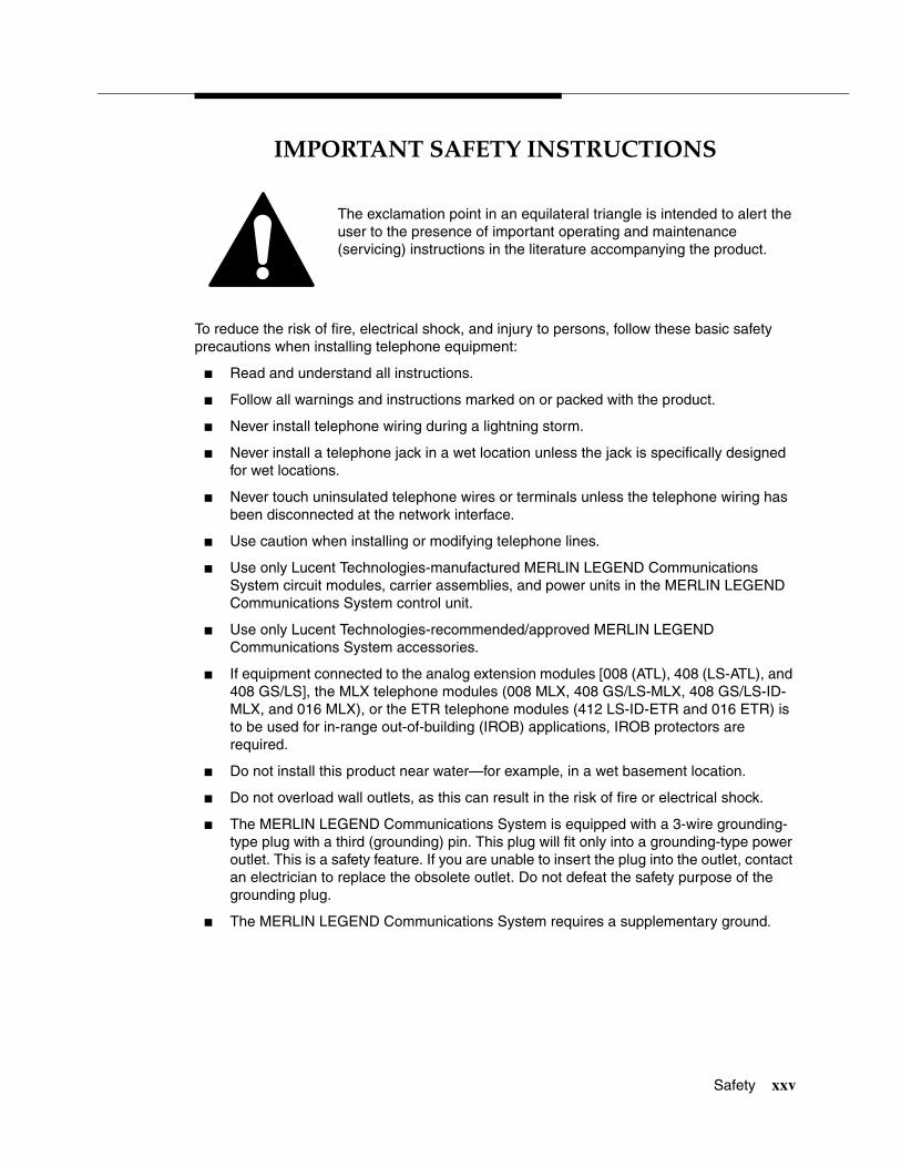
������������� ����������
The exclamation point in an equilateral triangle is intended to alert the user to the presence of important operating and maintenance (servicing) instructions in the literature accompanying the product.
To reduce the risk of fire, electrical shock, and injury to persons, follow these basic safety precautions when installing telephone equipment:
� Read and understand all instructions.
� Follow all warnings and instructions marked on or packed with the product.
� Never install telephone wiring during a lightning storm.
� Never install a telephone jack in a wet location unless the jack is specifically designed for wet locations.
� Never touch uninsulated telephone wires or terminals unless the telephone wiring has been disconnected at the network interface.
� Use caution when installing or modifying telephone lines.
� Use only Lucent Technologies-manufactured MERLIN LEGEND Communications System circuit modules, carrier assemblies, and power units in the MERLIN LEGEND Communications System control unit.
� Use only Lucent Technologies-recommended/approved MERLIN LEGEND Communications System accessories.
� If equipment connected to the analog extension modules [008 (ATL), 408 (LS-ATL), and 408 GS/LS], the MLX telephone modules (008 MLX, 408 GS/LS-MLX, 408 GS/LS-ID-MLX, and 016 MLX), or the ETR telephone modules (412 LS-ID-ETR and 016 ETR) is to be used for in-range out-of-building (IROB) applications, IROB protectors are required.
� Do not install this product near water—for example, in a wet basement location.
� Do not overload wall outlets, as this can result in the risk of fire or electrical shock.
� The MERLIN LEGEND Communications System is equipped with a 3-wire grounding-type plug with a third (grounding) pin. This plug will fit only into a grounding-type power outlet. This is a safety feature. If you are unable to insert the plug into the outlet, contact an electrician to replace the obsolete outlet. Do not defeat the safety purpose of the grounding plug.
� The MERLIN LEGEND Communications System requires a supplementary ground.

System Programming
Safety xxvi
� Do not attach the power supply cord to building surfaces. Do not allow anything to rest on the power cord. Do not locate this product where the cord will be abused by persons walking on it.
� Slots and openings in the module housings are provided for ventilation. To protect this equipment from overheating, do not block these openings.
� Never push objects of any kind into this product through module openings or expansion slots, as they may touch dangerous voltage points or short out parts, which could result in a risk of fire or electrical shock. Never spill liquid of any kind on this product.
� Unplug the product from the wall outlet before cleaning. Use a damp cloth for cleaning. Do not use cleaners or aerosol cleaners.
� Auxiliary equipment includes answering machines, alerts, modems, and fax machines. To connect one of these devices, you must first have a Multi-Function Module (MFM).
� Do not operate telephones if chemical gas leakage is suspected in the area. Use telephones located in some other safe area to report the trouble.
� For your personal safety, DO NOT install an MFM yourself.
� ONLY an authorized technician or dealer representative shall install, set options, or repair an MFM.
� To eliminate the risk of personal injury due to electrical shock, DO NOT attempt to install or remove an MFM from your MLX telephone. Opening or removing the module cover of your telephone may expose you to dangerous voltages.
SAVE THESE INSTRUCTIONS
! WARNING:
Release 7.0 Enhancements (April 1999) xxvii
��������������� ���������� 0
����������� ����������������������
Release 7.0 includes all Release 6.1 functionality, plus the enhancements listed below. For a description of features and enhancements in prior releases, see “Prior Releases: Features and Enhancements” in System Programming.
�������� �������� ��!���"�� ��� �����#������#� 0
One of the most important new capabilities of MERLIN LEGEND Release 7.0 is its support for MLS and ETR telephones, allowing existing customers with either telephones the ability to migrate to a MERLIN LEGEND Communications System. The MLS telephones include the MLS-6®, MLS-12®, MLS-12D®, MLS-18D®, and MLS-34D®. The ETR telephones include the ETR-6, ETR-18, ETR-18D, and ETR-34D. The Business Cordless 905 telephone and the TransTalk™ 9000 Digital Wireless System are also supported.
The MLS, ETR, and Business Cordless 905 telephones, as well as the TransTalk 9000 Digital Wireless System, require ETR station ports. To provide support for these telephones and for the TransTalk 9000 system, two new modules have been designed:
� 412 LS-ID-ETR Module. The 412 LS-ID-ETR module provides 4 LS trunks with Caller ID and 2 touch tone receivers (TTRs) plus 12 ETR station ports, including 4 with Tip/Ring (T/R) functionality. On the 412 LS-ID-ETR module, the first 8 ports are ETR ports only—these ports do not have T/R functionality. The remaining 4 ports (ports 9 through 12) can be

System Programming
xxviii Release 7.0 Enhancements (April 1999)
programmed to support either T/R or ETR, but not both simultaneously.This module does not have a separate PFT port. In the event of a power failure, port 12 becomes the PFT port for line 1. If the port is programmed for ETR operation, a single-line telephone must be plugged into the port for operation during power failure.
If caller identification is subscribed to from the local telephone company, the 412 LS-ID-ETR module displays the telephone number of incoming callers (from supported areas) on ETR and MLS display telephones. In addition, a button on the ETR and MLS telephone can be programmed to toggle between displaying caller name or caller number.
� 016 ETR Module. The 016 ETR module provides 16 ETR station ports, including 6 with T/R functionality and 4 TTRs. On the 016 ETR module, the first 10 ports are ETR ports only—these ports do not have T/R functionality. The remaining 6 ports (ports 11 through 16) can be programmed to support either T/R or ETR, but not both simultaneously.
$�������%�"����� ���#����&#������'��( 0
Release 7.0 increases the maximum number of digital telephones supported from 127 to 200 by introducing a new 016 MLX module. In addition, each of the 200 ports can support an MFM adjunct which increases the current 255 station endpoints to 400.
� 016 MLX Module. Each 016 MLX module provides 16 digital station ports and has an additional 32K of dual port RAM.
� Processor Module. The 016 MLX module can only be utilized with the CKE4 or later processor module with upgrade to R7.0 software. The CKE4 processor module provides the lead to access the additional 32K of RAM on the 016 MLX module.
)#�������#�����#��*����+��(�+���#��#����,� �����#�� 0
Prior to Release 7.0, no options were available for disabling intercom voice announcements at an MLX telephone when busy. In Release 7.0, a new option—Voice Announce on IDLE ONLY—is available with the existing Voice Announce feature. This new option allows a user to receive intercom voice announcements only when they are not active on another call.

New Features and Enhancements
Release 7.0 Enhancements (April 1999) xxix
-�#��(�&����.�����" 0
Priority call queuing provides the ability to:
� Place some callers ahead of others who are waiting for the same agent group.
� Give key clients priority over others.
� Automatically increase the number of agents answering calls during busy times, while continuing to offer callers the choice to leave a message instead of waiting.
� Keep costs down by handling toll free calls (calls arriving on 800 and 888 lines) before processing calls on local lines.
Priority call queuing is accomplished in Release 7.0 by allowing you to define a supportive relationship between calling groups. Calls that arrive in one calling group can be processed by another calling group when no one from the first calling group is available to answer the call. Through system programming, a calling group can be assigned a priority level between 1 (highest priority) and 32 (lowest priority) and then designated as a support group for another group.
&�����"�-��(������#��&�����*% 0
Release 7.0 continues to support Calling Party Number and adds a new functionality for Calling Party Name. By programming a button on the telephone or with a feature code through centralized programming, users are able to toggle between displaying the caller’s telephone number or the caller’s name. In order to use this feature, users must subscribe to caller identification from their local exchange carrier (LEC).
Calling Party Name can be 15 characters in length for MLX telephones as well as for ETR and MLS telephones. Calling Party Name is not recorded on SMDR reports. In addition, neither Calling Party Name nor Calling Party Number are displayed on analog multiline telephones.
This feature requires loop-start (LS) trunks. The existing LS-ID delay feature must be programmed for each line, as well. This prevents Calling Party Number and Name information from being lost when a call is answered too quickly.
Release 7.0 software also supports the Caller ID capability of the 408 GS/LS-ID-MLX module. Although previously orderable, the Caller ID capability of this module could not be used until Release 7.0 software became available.

System Programming
xxx Release 7.0 Enhancements (April 1999)
��,�/������+�����#� 0
Headset operation in Release 7.0 has been enhanced so that MLX headset operation more closely mimics the handset operation in the following ways:
� When a person is on a call using a headset and the headset auto-answer is turned on, the user hears a short ring when another call is coming in. In previous releases, this ring was not provided.
� When a person receives a voice-announced call and handles the call by using a headset and turning off the speakerphone, the associated LEDs (the DSS button and the inside Auto Dial button) for that extension at other telephones are lit. In previous releases, the LEDs for that extension did not light at the other telephones.
� When a reliable disconnect occurs on a headset-handled call, the associated LEDs (the DSS button and the inside Auto Dial button) for that extension at other telephones are turned off. In previous releases, the LEDs for that extension remained lit at the other telephones unless the user pressed the Headset Hangup button.
#���0 #���#��#��(���"�����" 0
Beginning in Release 7.0, you can program tip/ring ports to use rotary signaling. You can program any tip/ring port on an individual basis (including ports on the 412 LS-ID-ETR and 016 ETR modules that are programmed for tip/ring operation). The factory setting is that rotary signaling is disabled.
Whenever the system receives a rotary digit on a port, it determines if the port is programmed as rotary-enabled. If the port is rotary-enabled, the system processes the digit. If the port is not rotary-enabled, the digit is rejected. Touch-tone digits are always accepted by the port, regardless if it is rotary-enabled or not.
�1���#����&����*�2#����#�����#�����#� ��*��� 3 �%����#��� 0
For abandoned calls, you are now able to identify the queue or the agent where the call was abandoned. The MERLIN LEGEND Release 7.0 software has been modified so that either of the following occurs:
� If the caller hangs up while the call is in queue, the Auto Login/Logout Group ID is entered into the Station Message Detail Recording (SMDR) record.
� If the caller hangs up while the call is ringing at a group member’s extension, that group member’s extension number is entered into the SMDR record.
Release 6.1 Enhancements (August 1998) xxxi
��������������� ���������������� 0
������������������� ������ ������
Release 6.1 includes all Release 6.0 functionality plus the enhancements listed below.
���� ���� ��!��� 0
Release 6.1 enhances the functioning of the networked MERLIN LEGEND Communications System in a number of ways:
� Centralized Voice Messaging
� Group Calling Enhancements
� Transfer Redirect
� Direct Station Selector
� Call Forwarding
� SMDR
� Decrease in Call Set-Up Time
� PRI Switch Type Test

System Programming
xxxii Release 6.1 Enhancements (August 1998)
"�� ���#���$�����%����� 0
One or more MERLIN LEGEND Systems (Release 6.1 or later) can share the voice messaging system (VMS) of another MERLIN LEGEND System, provided the systems are directly connected to the system with the VMS. In this configuration, the system containing the VMS is known as the hub. This sharing of the VMS is called Centralized Voice Messaging. Centralized Voice Messaging includes the functions of voice mail, Automated Attendant, and fax messaging. See the Network Reference for detailed information about Centralized Voice Messaging.
Centralized Voice Messaging offers the following benefits:
� Private-networked MERLIN LEGEND Systems do not need a local VMS. Having systems use a centralized VMS instead of separate VMSs is more economical.
� Users who travel between sites can dial the same digits anywhere in the private network to access the voice messaging system. For example, a salesperson headquartered in Cincinnati can dial the same four digits at the company’s Los Angeles office to retrieve voice messages.
� Productivity is enhanced because messages can be forwarded and broadcast to all personnel within the private network.
� Calling groups on networked systems can send overflow coverage to a shared VMS, so that an incoming caller can leave a message instead of waiting in a queue.
� The VMS can light the Message Waiting lights on multiple MERLIN LEGEND Systems in a private network. This greater efficiency saves time because a user only has to look at his or her telephone to determine if he or she has a message.
&���'�"��������������� 0
A calling group can have a single non-local member that is defined by the Uniform Dial Plan and exists on another MERLIN LEGEND Communications System connected by a tandem trunk to the local system. If a calling group contains a non-local member, the non-local member must be the only member in the calling group. See the Network Reference for details.
A calling group containing a single non-local member can be used for the same purposes as a calling group containing local extensions, including:
� Night Service. Night Service coverage can be provided across a private network to a centralized Automated Attendant, a non-local calling group, a QCC queue, a DLC, or any individual extension on the remote system, such as a night bell.
Prior Releases: Features and Enhancements
Release 6.1 Enhancements (August 1998) xxxiii
� Group Coverage. Group Coverage can be provided across a private network to a VMS, a non-local calling group, a QCC queue, a DLC, or any individual extension on the remote system.
� Calling Group Overflow Coverage. Calling group overflow coverage can be provided by a centralized VMS, a non-local calling group, a QCC queue, a DLC, or any individual extension on the remote system.
� Calls Directed to Another System. Lines connected to remote systems can be answered by any extension programmed to answer the call, such as a centralized Automated Attendant or a system operator (QCC or DLC).
(��)���������� 0
When an Automated Attendant transfers a call to a non-local extension, the transferring MERLIN LEGEND System monitors the call to ensure that it is answered. If the non-local extension is not available, or the call is not answered within the transfer redirect timeout period (fixed at 32 seconds), the call stops ringing at the non-local destination and is redirected to the extension on the same system as the Automated Attendant that is programmed to receive redirected calls. This redirect extension can be a QCC queue, a calling group, or an individual extension.
*���� �+ ����+���� �� 0
Now users can press a Direct Station Selector (DSS) button for a non-local extension to make or transfer calls to that extension. No busy indication, however, is displayed by the DSS for non-local extensions.
"������ ����� 0
The Forward feature now can be used to send calls to non-local extensions across the private network.
+%*� 0
In addition to SMDR options for non-network calls placed to and from the local system, system managers now can program SMDR to log incoming and outgoing UDP calls, or they can choose to log no UDP calls. The factory setting is to record all UDP calls.
Customers who use a call accounting system may not want to fill the database with calls coming and going across the private network. These customers may choose not to log UDP calls.
System Programming
xxxiv Release 6.1 Enhancements (August 1998)
*���������"���+� �'�(��� 0
The setup time for a call across a private network has been reduced by programming the number of UDP digits expected.
��,�+ � ���(-'��(� 0
A new maintenance test, the PRI Switch Type Test, has been created to allow Lucent Technologies technicians or authorized dealers to automatically determine if each end of the PRI tandem trunks has been programmed correctly. The test works for directly connected MERLIN LEGEND Systems, not for DEFINITY®
systems.
For a PRI tandem trunk to operate correctly between two MERLIN LEGEND Systems, one system must have the PRI Switch Type set to Network, and the other system must have the PRI Switch Type set to PBX. If both ends of the PRI tandem trunk are programmed the same, problems occur in the communications between the two systems.
+�������./������ 0
Service Observing allows one extension to listen in on (observe) a call at another extension. A typical application of this feature is that of a Customer Service supervisor observing how a Customer Service representative handles calls.
The Service Observing group can listen to anywhere from one extension to all extensions in the system, including other Service Observers. Up to 16 Service Observing groups can be programmed. The Service Observer and the observed extension must be on the same system.
The observer activates Service Observing either by pressing a Service Observing button and then dialing an extension number, or by pressing a DSS or Auto Intercom button. The Service Observer must use an MLX telephone to observe an extension; the telephone at the observed extension can be of any type.
A warning tone that alerts the observer, the observed extension, and the caller that Service Observing is occurring can be set to on or off through System Programming. The factory setting is on.
0��+�% 0
The System Programming and Maintenance (SPM) software is now available in a Windows format called WinSPM. For R6.1 and later systems, WinSPM provides a graphical user interface (GUI) for those tasks most commonly performed by the system manager. Pictorial representations of system components, such as modules and their vintages and the creation of MLX telephone button labels

Prior Releases: Features and Enhancements
Release 6.0 Enhancements (February 1998) xxxv
appear on WinSPM. Supported in Windows 95, Windows NT, and Windows 98, WinSPM is also backwards-compatible with previous DOS versions of SPM and is available on CD-ROM.
0���� ��(�*����� 0
The MERLIN LEGEND Windows NT PBX driver is available in R6.1. When coupled with the CentreVU Telephony Services application, the driver provides true server-based Computer Telephony Integration (CTI). The new driver requires a MERLIN LEGEND System of Release 5.0 or later and servers and PCs that support the applications.
��������1���������� ����/���-������
Release 6.0 includes all Release 5.0 functionality, plus the enhancements listed below.
���� ���� ��! 0
In Hybrid/PBX mode systems only, MERLIN LEGEND Communications Systems can be networked with one another or with DEFINITY Enterprise Communications Server (ECS) and ProLogix™ Communications Systems in private networks. In previous releases, this functionality is available using tie lines, but users handle calls between networked switches as outside calls. In this release, dialing the pool access code is not necessary for a call going from one networked switch to another. Also, delay-start tie trunks or T1 trunks administered as PRI can act as tandem trunks to connect networked systems.
Available for Hybrid/PBX mode systems, the private network features of the MERLIN LEGEND Communications System Release 6.0 provide the following advantages for geographically dispersed organizational sites:
� Intersystem Calling. In a private network, users on one local system can call extensions on other systems in the network. Release 6.0 can support 2-, 3-, 4-, or 5-digit dial plans. They dial these extensions as inside calls. To implement this function, the system manager programs the extension ranges of remote networked switches to create a non-local dial plan. This programming does not actually affect numbering on the remote system. To correctly set up systems for transparent calling among non-local dial plan extensions, the system manager assigns networking tie and/or PRI tandem trunks to pools. Then he or she programs up to 20 patterns, associated routes, Facility Restriction Levels (FRLs), digit absorption, and digit prepending. This allows ARS-like routing of non-local dial plan calls. In

System Programming
xxxvi Release 6.0 Enhancements (February 1998)
addition, system managers can control whether calling name, calling number, or both are shown at MLX display telephones for incoming calls across PRI tandem trunks.
� Toll Savings. Private networked trunks may allow you to realize significant cost savings on long-distance and toll calls by performing tandem switching in the following two ways:
— Callers on a local system, or individuals dialing in to remote access at a local system, can reach the public switched telephone network (PSTN) via outside trunks connected to other systems in a private network, avoiding toll charges or decreasing the cost of toll calls. No special dialing is required. For example, an organization might have a main office in Boston and a subsidiary office in New Jersey connected by networked private tandem trunks between two systems. A user in the New Jersey office who wishes to make an outside call to the 617 area code (Boston) can do so through a line/trunk connected to the system in Boston. For example, he or she might dial, 916175551211. The local ARS tables would route this call over the private networked trunks and use the ARS tables of the remote system in Boston to route this call. The system managers at each end of a private network set up ARS and Remote Access features to implement this functionality.
— In addition, local organizations or incoming DID calls use private networked trunks to make intersystem calls between networked systems, which may be geographically distant from one another, also resulting in toll savings.
� Service Cost Savings. In addition to toll call savings, there are two ways that organizations can save on service costs incurred from telecommunications providers that provide public switched telephone network access:
— You order a point to point T1 facility from a service provider, then use system programming to set it up for PRI signalling. As necessary, a service provider can provide amplification on the T1 facility, but does not supply switching services.
— You can tailor your use of PRI B-channels with drop-and-insert equipment that allows fractional use of B-channels for dedicated data/video communications between systems at speeds greater than 64 kbps per channel or 128 kbps for 2B data, while keeping the remaining B-channels available for PRI voice traffic. The PRI D-channel must remain active.
— You can tailor use of T1 channels to support both T1-emulated tandem tie service and T1 Switched 56 service for data communications at 56 kbps per channel, allowing 2B data transfers at 112 kbps. You can also use drop-and-insert equipment to provide fractional T1 use.
Prior Releases: Features and Enhancements
Release 6.0 Enhancements (February 1998) xxxvii
� Voice Mail and Auto Attendant. Networked systems (prior to Release 6.1) should have their own local voice mail and/or auto attendant applications as well as their own external alerts and Music-On-Hold sources. A single Auto Attendant, however, can transfer calls throughout the network. It can answer only those calls that arrive on the PSTN facilities of the system where it is connected.
Although many features are available using tie trunks for network connectivity, PRI tandem trunks provide greatly enhanced features and faster call setup. For this reason, PRI is recommended over tie functionality in private networks.
&���'�"��������������� 0
Release 6.0 and later systems include Group Calling features that enhance group calling operations.
2�����"�� ��� 0
The system manager can control the maximum number of calls allowed in the primary calling group queue for calls that arrive on certain facilities often assigned to calling groups. When the number of the calls in queue reaches the programmed maximum, subsequent callers receive a busy signal.
Queue control applies to calls received on the following types of facilities:
� Direct Inward Dialing (DID)
� PRI facilities programmed for dial-plan routing
� All calls transferred from a voice messaging interface (VMI) port
� Dial-in Tie
Queue control also applies to internal calls to a calling group and calls to a calling group through the Queued Call Console (QCC).
Internal calls that dial #0 or #800 and are directed to a calling group administered as Position-Busy Backup are eligible for queue control. Calls that come in on a trunk assigned to the QCC are not eligible for queue control if the call is directed to a calling group designated as Position-Busy Backup.
Remote-access calls to a calling group, coverage calls directed to a calling group, calls directed to a calling group through QCC Position-Busy Backup, and all other outside calls are not eligible for queue control.

System Programming
xxxviii Release 6.0 Enhancements (February 1998)
����' 34���.���)�� 0
System managers can activate the Prompt-Based Overflow option. This option allows callers waiting in queue and listening to a delay announcement to press the # key in order to reach the overflow receiver for the group, which may be the QCC queue or another calling group (including a calling group assigned for a voice mail system).
All three overflow distribution options—based on the number of calls, the time a caller has waited, and according to the caller’s prompt—may be used at one time. In this case, time-based and number-of-calls based options take precedence over overflow distribution based on the caller’s prompt.
When prompt-based overflow distribution is used, an extra TTR must be provided for each delay announcement device assigned to the associated calling group. The delay announcement informs the caller of the # key option to exit the queue and leave rather than waiting for an agent. If no TTR is available when a calling group call arrives, the call is not sent to a delay announcement extension.
"�� ��5�(��)���������� ��"������ ����� 0
Centrex Transfer via Remote Call Forwarding can be used in all system modes of operation to send outside calls to a remote telephone number or another Centrex station. In this context, the term outside calls refers to calls from outside the communications system, which may originate at extensions in the Centrex system that are not connected to the local MERLIN LEGEND Communications System.
An outside call that uses this feature is defined as a call that arrives on an analog Centrex loop-start line at the MERLIN LEGEND Communications System. It may arrive directly or be transferred without consultation or without transfer supervision (in the case of an automated attendant). The forwarding call to the outside number is made on the same line/trunk on which the call arrived, conserving system facilities. The following considerations and rules apply:
� Only outside Centrex calls are forwarded using this feature.
� The system must be equipped with analog loop-start Centrex lines and all loop-start lines in the system must be Centrex facilities. Loop-start lines do not have to provide reliable disconnect for use by the Centrex Transfer via the Remote Call Forwarding feature.
� To transfer calls outside the Centrex system, the organization must subscribe to a Centrex trunk-to-trunk transfer feature.
Activating Centrex Transfer via Remote Call Forwarding is just like activating regular Remote Call Forwarding and requires that Remote Call Forwarding be enabled for the extension. However, the user dials * instead of a dial-out code, and a Pause character may be required after the *. The Centrex service provider determines whether the Pause is needed.
Prior Releases: Features and Enhancements
Release 5.0 Enhancements (June 1997) xxxix
Pause cannot be originated from a single-line telephone or a remote access user. A multiline telephone user in the local system must enter an authorization code to activate the feature.
A remote access user may activate the feature without using an authorization code. Barrier code requirements, however, do apply.
�� ����# ����"���������� � "�� ��� ����� 0
In Release 6.0 and later Key or Hybrid/PBX mode systems, forwarding features (including Centrex Transfer via Remote Call Forwarding, but excluding Follow Me) can be activated or deactivated at a multiline telephone by entering the authorization code for the extension from which calls are to be forwarded. The user enters the authorization code, then activates or deactivates the forwarding feature in the normal fashion. This is especially useful for a single-line telephone user who must include a Pause character in a Centrex Transfer via Remote Call Forwarding dialing sequence, because the character cannot be dialed at a single-line telephone. It is also useful when activating Call Forwarding or Remote Call Forwarding at phantom stations or via remote access (for example, from another switch in the network). No other features can be used by entering an authorization code in this fashion.
������6�1���������� ��7�������8�
Release 5.0 includes all Release 4.2 functionality, plus the enhancements listed below.
"��'� ���(���'���-�,� ��� �����"(,� 0
Beginning with Release 5.0, a PassageWay® Telephony Services CTI link from the MERLIN LEGEND Communications System to a LAN server running Novell® NetWare® software allows Lucent Technologies-certified telephony applications to control and monitor MLX and analog multiline telephone (BIS only) operations. The physical connection for the CTI link is an MLX port on a 008 MLX or 408 MLX module on the MERLIN LEGEND Communications System control unit and an ISDN link interface card plugged into the customer’s server. The feature is available for Hybrid/PBX mode systems only.
System Programming
xl Release 5.0 Enhancements (June 1997)
NOTES:� The NetWare server software version must be 3.12, 4.1, or 4.11.
� The 008 MLX and 408 MLX modules must have a firmware vintage other than 29. If the module has firmware 29, programming a CTI link on the module is prevented. An earlier or later vintage firmware is supported.
4���"���"�� ���� 0
A CTI link application on a user’s computer can assume basic call control of the user’s analog multiline or MLX telephone’s SA buttons. Basic call control includes:
� Answering calls arriving on an SA button.
� Making calls from an SA button.
� Hanging up calls.
� Holding and retrieving a call on hold at the user’s extension.
NOTE:Transfer and three-way conference, when handled through a CTI link application, provide the original caller’s calling number information or other information to the transfer receiver or new conference participant, if the user has screen-pop capability.
+��������' 0
Screen pop occurs when the calling number, called number, or other user-defined identifier (such as an account code that a voice-response unit prompts the caller to dial) is used to display a screen associated with the far-end party. For example, Caller ID services can be used to support screen pop on a system that includes a CTI link; using the calling party number as a database key code, information about a caller automatically appears on the user’s computer screen when the call arrives at the extension. Depending on the application, screen pop may be available for calls that arrive on line buttons other than SA buttons and/or calls that are answered manually at the telephone rather than by the application.
Screen pop can occur on incoming calls from the following sources:
� Calling group distribution.
� ISDN PRI Routing by Dial Plan.
� An extension on the MERLIN LEGEND Communications System.
� Remote access.

Prior Releases: Features and Enhancements
Release 5.0 Enhancements (June 1997) xli
NOTE:In the case of remote access calls, the only information that the application can collect about the caller is the remote telephone number.
� A transfer of a call that was answered by a voice response unit.
� A transfer, redirection, or conference of a call that was answered at a Direct-Line Console (DLC) or at a Queued Call Console (QCC).
NOTES:� DLCs may use CTI applications. If they do, they perform the same way
as other extensions. A DLC assigned to use a CTI link application is a monitored DLC. When a DLC is used as a regular operator console and is not using a CTI link extension, it is non-monitored.
� Calls to a QCC or a DLC not using a CTI application do not initiate screen pop at the operator position. However, when an operator directs a call to an extension using a CTI application, caller information does initiate screen pop. If the DLC is non-monitored, screen pops can occur after the DLC releases the call.
� Calls transferred from Cover buttons on non-monitored DLCs do not initiate screen pop at the destination extension.
9� :������ ��� 0
The Release 5.0 HotLine feature is designed for retail sales, catalogue sales, and other types of businesses and organizations, and is available in all three modes of system operation. It allows a system manager to program a single-line telephone extension connected to an 008 OPT, 012, or 016 module as a HotLine. When a user lifts the handset at the HotLine extension, the telephone automatically dials the inside extension or outside telephone number programmed as the first Personal Speed Dial number (code #01) for the extension. The system does not permit calls to be transferred, put on hold, or conferenced. (A user can press the telephone’s Hold button, if it has one, to put a call on local hold, but the call cannot be redirected in any way. Switchhook flashes are ignored.)
Personal Speed Dial codes can be programmed from the extension prior to HotLine assignment (a system programming function). Alternatively, a Personal Speed Dial code can be programmed from the single-line telephone after HotLine operation is assigned. However, because of security considerations, this is a one-time opportunity. Once the Personal Speed Dial number is programmed, any changes to it or any other extension programming must be performed using centralized telephone programming.

System Programming
xlii Release 5.0 Enhancements (June 1997)
Any type of inside or outside line that is normally available to a single-line telephone can be assigned to a HotLine extension. Generally, the HotLine telephone does not receive calls, and its lines should be set to No Ring.
! SECURITY ALERT:If a HotLine extension accesses a loop-start line, that line should provide reliable disconnect and be programmed for reliable disconnect. Otherwise, a user at the extension may be able to stay on the line after a call is completed and then make a toll call.
&���'�"��������������� 0
Release 5.0 and later systems include Group Calling features that enhance group calling operations.
%� �,����9�� �(-'� 0
In addition to the Circular (factory setting) and Linear hunt types supported in earlier releases, a third hunt type distributes calling group calls in an order based on which agent has waited the longest since transferring or hanging up on an incoming calling group call. For some applications, this hunt type is more efficient than the circular type because it takes into account the varying duration of calls. The system distributes calls based on when an agent last completed a call, not on when he or she last received one. This hunting method ignores non-calling group calls. For example, if an agent transfers a call that arrived on a line not assigned to the calling group, the calling group member’s most-idle status is unaffected.
�*��-������������ �*����� 0
The system manager can designate as many as ten primary delay announcement devices per group, rather than the single device for each group that is available in Release 4.2 and earlier systems. Furthermore, an additional secondary delay announcement device can be specified, for a total of ten primary device extensions and one secondary device extension per group.
A primary delay announcement device operates in the same fashion as a single delay announcement device, playing once, as soon as it is available, for the caller who has waited the longest for a calling group agent and has not heard a primary delay announcement. If a secondary announcement device is used, it can use the factory setting, which plays the announcement once, or it can be set to repeat the announcement after a certain amount of time. The system manager programs the time (0–900 seconds) between announcements. This setting controls both the interval between primary and secondary announcements and the interval between repetitions of the secondary announcement, if it is set to repeat. (See “Calling Group Options” in Chapter 4 of System Planning for guidelines on setting the delay.)

Prior Releases: Features and Enhancements
Release 5.0 Enhancements (June 1997) xliii
The primary and secondary announcement options, when used together, allow an initial message to play for callers, followed by a repeating announcement that, for example, urges callers to stay on the line and wait for a calling group member.
Two or more groups may share an announcement device.
A primary delay announcement device can be programmed as a secondary delay announcement device.
��������"��3��32����������(������� 0
Three Calls-in-Queue Alarm thresholds can be set to more clearly indicate the real-time status of the calls waiting in the queue according to the behavior of programmed Calls-in-Queue Alarm buttons. In earlier releases, only one Calls-in-Queue Alarm Threshold setting is available to activate the LEDs at programmed Calls-in-Queue Alarm buttons for a calling group.
Using all three levels, the system manager sets Threshold 3 to the highest value, Threshold 2 to a middle value, and Threshold 1 to the lowest value. A Calls-in-Queue Alarm button indicates the severity of the alarm conditions in the following ways:
� If the number of waiting calls is less than the value programmed for Threshold 1 or drops below that level, the LED is unlit.
� If the number of waiting calls is greater than or equal to the Threshold 1 value but less than the Threshold 2 value, the LED flashes.
� If the number of waiting calls is greater than or equal to the Threshold 2 value but less than the value for Threshold 3, the LED winks.
� If the number of waiting calls is greater than or equal to the highest value, Threshold 3, the LED lights steadily.
NOTE:A Direct Station Selector (DSS) button that is used as a Calls-in-Queue Alarm button can only indicate two threshold levels, either by flashing or by lighting steadily. If a calling group must use this type of Calls-in-Queue Alarm button, only two threshold levels should be programmed.
If all three thresholds are set to the same value, the result is one threshold only with LED state either off or on (steady). If two values are the same, then the result is two alarm levels (flash, steady). The factory setting is one call for all three thresholds, with LED states of off and steady.
An external alert signals only when the number of calls in the queue meets or exceeds the programmed Threshold 3 value.

System Programming
xliv Release 4.2 Enhancements (June 1997)
%:;36����%:;36*�(���'���� 0
The MLX-5 nondisplay and MLX-5D display telephones are compatible with all system releases. The display telephone includes a 2-line by 24-character display, and both telephones come with five line buttons. In systems prior to Release 5.0, the MLX-5 and MLX-5D telephones are treated as MLX-10 and MLX-10D telephones, respectively. As of Release 5.0, the system recognizes the MLX-5 and MLX-5D telephones as 5-button telephones.
If these telephones are connected to communications system releases prior to 5.0, they are recognized by the communications system as 10-button telephones.
������<�=���������� ��7�������8�
Release 4.2 includes all Release 4.1 functionality, plus the enhancements listed below. There are no hardware changes for Release 4.2.
���� ������� ��!�+ � ������+�������.' ���)���,+*�������-�� ��,� ��)������,� 0
Release 4.2 of the system supports connectivity to MCI® or local exchange carrier (LEC) PRI services and to the following central office switch types (in addition to the 4ESS™ and 5ESS® switch types that carry AT&T Switched Network services):
� NORTEL® DMS™-100 BCS 36 for local exchange carrier services.
� NORTEL DMS-250 generic MCI07, serving the MCI network.
� Digital Switch Corporation DEX600E generic 500-39.30, serving the MCI network.
Beginning with Release 4.2, the following MCI PRI and PRI local exchange carrier (LEC) services (along with AT&T Switched Network services) can be provided to users of the MERLIN LEGEND Communications System:
� MCI Toll Services for DMS-250 or DEX600E switch type:
— MCI Prism® service for domestic outgoing long-distance and international voice calls; for domestic outgoing 56-kbps restricted, 64-kbps unrestricted, and 64-kbps restricted circuit-switched data calls.
— MCI VNet® service for incoming and outgoing domestic and voice calls; for 56-kbps restricted, 64-kbps restricted, and 64-kbps unrestricted circuit-switched data calls.
— MCI 800 for domestic, toll-free incoming voice calls.

Prior Releases: Features and Enhancements
Release 4.2 Enhancements (June 1997) xlv
— MCI 900 service numbers.
� LEC services for DMS-100 switch types:
— DMS Virtual Private Network service for calls between the MERLIN LEGEND Communications System and another communications system (such as another MERLIN LEGEND Communications System).
— DMS INWATS (Inward Wide Area Telephone Service) for domestic toll-free incoming voice calls.
— DMS OUTWATS (Outward Wide Area Telephone Service) for domestic outgoing long-distance voice calls.
— DMS FX (foreign exchange) to provide local call rating for calls from the local exchange to the area serviced by the foreign exchange.
— DMS tie trunk service to provide private exchange call rating for calls placed on a dedicated central office facility between the MERLIN LEGEND Communications System and another communications system (such as another MERLIN LEGEND Communications System).
,�'������� � ��+ ����%����*� �������������+%*������+�''�� �)���%��:,��:�&��*���'�� ����''��� ��� 0
The SMDR feature is enhanced to provide more details about calling group agent activities and to help system managers assess the effectiveness of call centers in terms of both agent performance and the adequacy of facilities to handle inbound calls. These improvements apply to calling groups that are programmed as Auto Login or Auto Logout type. The SMDR and MERLIN LEGEND Reporter features listed are administrable:
� TALK Field. For Auto Login and Auto Logout calling groups, the TALK field records the amount of time a calling group agent spends on a call.
� DUR. (DURATION) Field. For Auto Login and Auto Logout calling groups, call timing begins when a call arrives at the MERLIN LEGEND Communications System and not after a preset number of seconds. Call timing ends when the call is disconnected; either the caller or the agent hangs up. This allows the system manager to determine how long a caller waited for an agent’s attention.
� Coding of Calls on Reports. An asterisk (*) appears in the call record when:
— A call is not answered by an Auto Login or Auto Logout calling group agent and is abandoned while waiting for an agent.

System Programming
xlvi Release 4.2 Enhancements (June 1997)
— The call is answered by someone not a member of an Auto Login or Auto Logout calling group.
An exclamation point (!) signals that an Auto Login or Auto Logout agent handled a call that was answered by someone who was not a member of that Auto Login or Auto Logout with Overflow group. An ampersand (&) in the call record indicates that the group’s overflow receiver answered the call.
%��:,��:�&��*���'�� �� 0
MERLIN LEGEND Reporter provides basic call accounting system reports for all incoming calls to Auto Login or Auto Logout type calling groups. MERLIN LEGEND Reporter assists in determining the effectiveness of calling group agents, assessing the level of service provided to callers, and ascertaining whether adequate incoming telephone lines and agents are available to handle peak-call load. The SMDR Talk Time option sets up special call records used by MERLIN LEGEND Reporter. The default is off, in which case the Release 4.0 SMDR reports are available. If the option is set to on, the following new reports are provided:
� Organization Detail Report
� Organization Summary and Trends Report
� Selection Detail Report
� Account Code Report
� Traffic Report
� Extension Summary Report
� Data Report
� Talk and Queue Time Distribution Report
� Time of Day Report
� ICLID Call Distribution Report
� Facility Grade-of-Service Report
%�� ��������������� 0
"����� ��������� ����������� 0
Beginning with Release 4.2, the most recent permanent error alarm is not shown on the System Error Log menu screen but is available as an option from that screen. For details, refer to the maintenance section of the technician guide, Installation, Programming, and Maintenance.

Prior Releases: Features and Enhancements
Release 4.1 Enhancements (June 1997) xlvii
���������5 ������,�)��� ������'�� 0
Beginning with Release 4.2, the Extension Information Report includes the Extension Status and supervisory mode of each extension.
������<������������ �7�������8�
Release 4.1 includes all Release 4.0 functionality, plus the enhancements listed below. There are no hardware changes in Release 4.1.
"�������(���������������)��,�������� �5 ����� 0
Beginning with Release 4.1, coverage timers, which control the duration of the delay before calls are sent to each level of coverage, are changed as follows:
� The Group Coverage Ring Delay (1–9 rings) is programmed on individual extensions and replaces the Coverage Delay Interval programmed systemwide in previous releases.
� The Primary Cover Ring Delay (1–6 rings) and Secondary Cover Ring Delay (1–6 rings), programmed on individual extensions, replace the Delay Ring Interval programmed systemwide in previous releases.
These enhancements allow the system manager to customize coverage call delivery to match individual extensions’ call-handling requirements.
���� �+������� � ��"�������"�� ��� 0
Beginning with Release 4.1, a system manager can enable the Night Service Coverage Control option to automatically control the status of telephones programmed with Coverage VMS (voice messaging system) Off buttons, according to Night Service status.
When Coverage Control is enabled and the MERLIN LEGEND Communications System is put into Night Service, all programmed Coverage VMS Off buttons are automatically turned off (LED is unlit) and all eligible outside calls are sent to the assigned voice messaging system calling group with normal ringing delay. When Night Service is deactivated during the day, all programmed Coverage VMS Off buttons are automatically turned on (LED is lit) and voice mail coverage is disabled for outside calls.
Users can override the Coverage VMS Off button status at any time by pressing the programmed Coverage VMS Off button to turn the LED on or off.

System Programming
xlviii Release 4.1 Enhancements (June 1997)
���� �+�������&���'�:����������� 0
Beginning with Release 4.1, a system manager can assign lines to Night Service groups to control handling of after-hours calls received on individual lines. This capability replaces the automatic assignment to Night Service groups of only those lines that ring on the Night Service operator console. An outside line must be assigned to a Night Service group to receive Night Service treatment.
With this enhancement, Night Service can be activated and deactivated on lines that do not appear on operator consoles (for example, personal lines), and lines appearing at operator positions can be excluded from Night Service.
��� ������4�- 0
Beginning with Release 4.1, the Forward, Follow Me, and Remote Call Forward features are enhanced to remove the requirement that a call be ringing at an extension before it can be forwarded. With the Forward on Busy enhancement, a call to an extension with no available SA or ICOM buttons is forwarded immediately to the programmed destination, preventing the caller from hearing a busy signal from the intended call recipient’s extension.
%�� ������(� ����)���4�,������ ��� � ������ ��)�%�� ������9�� �&���'��%:9&� 0
Beginning with Release 4.1, the NI-1 BRI (National Integrated Services Digital Network-1 Basic Rate Interface) Provisioning Test Tool is enhanced to include testing for BRI facilities that are part of Multiline Hunt Groups (MLHGs).
The NI-1 BRI Provisioning Test Tool is used by Lucent Technologies maintenance personnel on MERLIN LEGEND Communications Systems that include an 800 NI-BRI module. Technicians use the tool during system installation and maintenance to test the functionality of the BRI lines and to report analyzed results.

Prior Releases: Features and Enhancements
Release 4.0 Enhancements (March 1996) xlix
������<�1���������� ��%���������
Release 4.0 includes all Release 3.1 functionality, plus the enhancements listed below.
+�''�� �)���>'� ��=11��5 ����� 0
An expanded dial plan supports up to 200 tip/ring devices.
+�''�� �)���� �����,+*��4�,�+������� 0
This service (Hybrid/PBX and Key modes) provides an alternative to loop-start and ground-start lines/trunks for voice and digital data connectivity to the central office. Each of the two B-channels (bearer channels) on a BRI line can carry one voice and one data call at any given time. The data speeds on a B-channel are up to 28.8 kbps for analog data and up to 64 kbps for digital data, which is necessary for videoconferencing and other high-speed applications. Release 4.0 supports the ISDN Ordering Code (IOC) Package “S” (basic call handling) service configuration and Multiline Hunt service configuration on designated central office switches.
�� �"�� ����>�� �%����� 0
Release 4.0 supports a new NI-BRI line/trunk module and a higher-capacity tip/ring module.
�11��,34�,�%����� 0
This new module connects NI-BRI trunks to the MERLIN LEGEND System for voice, high-speed data, and video transmission.
1���(�'?�����%����� 0
This new module supports a 200-extension dial plan by providing 16 ports for tip/ring devices. Applications that use a tip/ring interface can connect to this board. All 16 ports can ring simultaneously. Four touch-tone receivers (TTRs) are included on the module as well. The module’s ringing frequency (default 20 Hz) can be changed, through programming, to 25 Hz for those locations that require it.

System Programming
l Release 4.0 Enhancements (March 1996)
*� ����/������� ���)��� ���1����(?�� �� �,34�, %����� 0
The Personal Computer Memory Card International Association (PCMCIA) technology, introduced in Release 3.0, continues to support these two modules for installation and upgrade in Release 4.0. A Release 3.0 or later processor is required for PCMCIA technology.
+�''�� �)���=4�* ��''��� ���� 0
A Lucent Technologies-certified group and desktop video application can use two B-channels to make video/data calls when connected to a single MLX extension jack programmed for 2B data. The 2B data devices must be equipped with ISDN-BRI interfaces. NI-1 BRI, PRI, or T1 Switched 56 facilities support 2B data communications at 112 kbps (using two 56-kbps channels) or 128 kbps (using two 64-kbps B-channels). This feature is available for Hybrid/PBX and Key modes only.
+�''�� �)���(��+ � �����6�*��� � * (�������� 0
For Hybrid/PBX and Key mode systems, Release 4.0 expands support of T1 functionality by providing access to digital data over the public switched 56-kbps network, as well as to digital data tie-trunk services. Users who have T1 facilities for voice services can now use them for video or data calls at rates of 56 kbps per channel (112 kbps for video calls using 2B data). The Release 4.0 offering also includes point-to-point connectivity over T1 tie trunks, allowing customers to connect two MERLIN LEGEND Communications Systems or a MERLIN LEGEND Communications System with a Lucent Technologies DEFINITY G1.1 Communications System or DEFINITY Enterprise Communications Server. The two communications systems can be co-located or can be at different sites.
��� ������*��-�.' ��� 0
Each user can program a Forwarding Delay setting for the Forward, Remote Call Forwarding, or Follow Me features. The forwarding delay is the number of times that a call rings at the forwarding extension before the call is sent to the receiver. The delay period gives the original call recipient time to answer or to screen calls by checking the displayed calling number (if available). The delay can be set from 0 to 9 rings. The factory setting for the forwarding delay is 0 rings (no delay).

Prior Releases: Features and Enhancements
Release 4.0 Enhancements (March 1996) li
$�����������������2������"���"����� 0
The system manager can enable the fifth Call button on a QCC console (Hybrid/PBX mode only) to announce a call on another user’s speakerphone (providing the destination telephone has a voice announce-capable SA button available). A QCC cannot receive voice-announced calls; they are received as ringing calls. The factory-set status for the fifth Call button is voice announce disabled.
(���34���.' ����)��.���)�� �� "����� &���' 0
Release 4.0 has added a time limit for calls in queue in addition to the previous number of calls limit. If the Overflow Threshold Time option is set to a valid number between 1 and 900 seconds, calls that remain in the calling group queue for the set time are sent to the overflow receiver. If the overflow threshold time is set to 0, overflow by time is turned off. The factory-set time limit is 0 seconds (off).
+�����3:����(���'�������������� 0
The following changes enhance the performance of single-line telephones:
� Disable Transfer. Through centralized telephone programming, the system manager can disable transfer by removing all but one SA or ICOM button from the extension.
� No Transfer Return. When a handset bounces in its cradle, the system interprets this as a switchhook flash and attempts to transfer a call. When the transfer attempt period expires, the user’s telephone rings. Release 4.0 eliminates this unintended ringing by disconnecting the call in situations where a switchhook flash is followed by an on-hook state and a dial tone is present.
� Forward Disconnect. All ports on 008 OPT, 012, and 016 modules now send forward disconnect to all devices connected to them when forward disconnect is received from the central office. This enhancement prevents the trunk/line from being kept active when one end disconnects from the call. If an answering machine is connected to the port, it does not record silence, busy tones, or other useless messages. This operation is not programmable.
+����3*��� �� ����)���+�% 0
Release 4.0 has increased system security by requiring a 7-digit password for system managers or technicians who use System Programming and Maintenance (SPM) to perform programming or the Trunk Test procedure. This password is for use in addition to a remote access barrier code.
System Programming
lii Release 3.1 Enhancements (March 1996)
������@������������ ��%���������
Release 3.1 includes all Release 3.0 functionality, plus the enhancements listed below.
"����� ��� ����"���!����)���+ ��"��� 0
Beginning with Release 3.1, a system manager can add star (*) codes to Allowed and Disallowed Lists to help prevent toll fraud. Star codes, typically dialed before an outgoing call, enable telephone users to obtain special services provided by the central office. For example, in many areas, a telephone user can dial *67 before a telephone number to disable central office-supplied caller identification at the receiving party’s telephone. You must contract with your telephone service provider to have these codes activated.
When users dial star codes, the system’s calling restrictions determine whether the codes are allowed. If they are allowed, the system’s calling restrictions are reset, and the remaining digits that the users dial are checked against the calling restrictions.
(���!3 �3(���!�(��)���+� �)��������5 ����� 0
This enhancement to the Transfer feature enables the system manager to allow or disallow trunk-to-trunk transfer on a per-extension basis. In Release 3.1 and later systems, the default setting for all extensions is restricted.
�������/���+������*���(����(���� 0
The system manager can assign a second dial tone timer to lines/trunks, in order to help prevent toll fraud (for example, when star codes are used). After receiving certain digits dialed by a user, the central office may provide a second dial tone, prompting the user to enter more digits. If this second dial tone is delayed, and the user dials digits before the central office provides the second dial tone, there is a risk of toll fraud or misrouting the call. The second dial tone timer enables the system manager to make sure that the central office is ready to receive more digits from the caller.
+����� -���������� 0
The sections below outline security measures that are implemented in Release 3.1 and later systems.
Prior Releases: Features and Enhancements
Release 3.1 Enhancements (March 1996) liii
*���� ���:� �,������������/���.) ������ ��� � ��(�������� 0
A factory-set Disallowed List 7 contains default entries, which are numbers frequently associated with toll fraud. By default, Disallowed List 7 is automatically assigned to both generic and integrated voice messaging interface (VMI) ports used by voice messaging systems. The system manager can manually assign this list to other extensions.
*�)�� ������*��3.� �"����� ��� ��� )�� ��� �5 ����� 0
The default setting for the pool dial-out code restriction (Hybrid/PBX mode only) is restricted. No extension or remote access user with a barrier code has access to pools until the restriction is removed by the system manager.
*�)�� �.� ����� ��� ����)���$%,���� 0
Ports assigned for use by voice messaging systems (generic or integrated VMI ports) are now assigned outward restrictions by default. If a voice messaging system must be allowed to call out (for example, to send calls to a user’s home office), the system manager must remove these restrictions.
! SECURITY ALERT:Before removing restrictions, it is strongly recommended that you read Appendix A, “Customer Support Information,” in System Programming.
*�)�� ������ -��� ��� ���:���� ���:� )�� $%, ��� 0
The default Automatic Route Selection (ARS) FRL for VMI ports is 0, restricting all outcalling.
*�)�� �)��� ���*�)�� �:����(/��� 0
The default Automatic Route Selection (Hybrid/PBX mode only) FRL has changed to 2 for the Default Local table. System managers can easily change an extension’s default FRL of 3 to 2 or lower to restrict calling. No adjustment to the route FRL is required.
System Programming
liv Release 3.0 Enhancements (August 1994)
�� �%�� ����������������)���(� ���.� ������(���! 0
Technicians must enter a password in order to perform trunk tests.
! SECURITY ALERT:The enhancements in Release 3.1 help increase the security of the MERLIN LEGEND System. To fully utilize these security enhancements, be sure to read and understand the information in these upgrade notes and in the relevant system guides.
������@�1���������� ������ ����<� 0
Release 3.0 includes all Release 2.1 functionality plus the enhancements listed below.
�A��'��� 0
New hardware includes a variety of components. Additional details are included elsewhere in this book.
� CPU modifications include:
— A processor running at 16 MHz with a 32-bit wide data bus.
— 1.5 MB of non-volatile (battery-backed) RAM.
— 4.0 MB of Flash ROM.
— PCMCIA memory card interface.
— A full-duplex 1200/2400 bps modem.
— Error/Status code display for maintenance support.
� An 800 GS/LS-ID line/trunk module delivers the calling party’s telephone number to the customer premises (MLX display telephones only) if the service is subscribed to by the customer and if it is supported by the caller’s telephone company.
� Support for:
— MDC 9000 (six-line, cordless).
— MDW 9000 (six-line, cordless, wireless).
— 8101 (single-line telephone, desk or wall-mount, data/fax jack, selectable positive disconnect).
Prior Releases: Features and Enhancements
Release 3.0 Enhancements (August 1994) lv
— 2500YMGL and 2500 MMGL (single-line desk telephones, selectable positive disconnect).
— Picasso™ Still-Image telephone (for interactive display of still images).
— Videophone 2500 single-line telephone with interactive video display
� Pre-fabricated and pre-drilled backboard.
,� �� ���B�>'����������� � ���B����%�� ����� 0
These are the new MERLIN LEGEND Communications System capabilities:
� SPM (Release 3.18) conversion of translations from Release 1.0, 1.1, 2.0, and 2.1 to 3.0.
� Remote operation at 1200/2400bps.
� Advice and feedback administration screens for new Release 3.0 functionality.
� PCMCIA Memory Card Interface (a Release 3.0 processor board required) allowing:
— System software installation.
— System software upgrade.
— 800 GS/LS-ID port module firmware upgrade.
— Integrated backup and restore of translations.
— Automatic and manual options for backup and restore are available on the system. Automatic backup can be scheduled weekly or daily to fit the customer’s needs.
� Inter-digit dialing timer values are programmable.
� Inspection of Lines/Trunks displays only those lines and trunks configured on system rather than all 80 facilities.
� Extensions and facilities in Maintenance Busy (both manual and automatic) can be identified by the maintenance monitor.
>����� ��� 0
+����� - 0
The Remote Access feature allows people at remote locations to enter the system by dialing the number of a line or trunk designated for remote access. The system

System Programming
lvi Release 3.0 Enhancements (August 1994)
can be programmed to require the remote user to dial a barrier code (a type of password) after reaching the system. In earlier versions, the systemwide barrier code length is fixed at four digits. Release 3.0 allows a systemwide barrier code length ranging from a minimum of four digits to a maximum of 11 digits, with a factory setting of seven digits. SMDR records are enhanced to provide information for remote access calls. If the remote access call is received on a facility providing Caller ID information (see below), the SMDR report can help trace the call.
"�����,* 0
Caller information (telephone number) is furnished to MLX display telephones by an 800 GS/LS-ID module using the LS (loop-start) option. This allows customers to screen calls before answering the telephone, as well as providing calling party information for use with various applications. This function is available only when the customer subscribes to caller identification service from the telephone company, if the telephone company supports that service.
+�����+- ���������++�� 0
A telephone may have up to 27 Shared SA buttons to expand extension coverage.
�� ����# ����"��� 0
The Authorization Code feature allows you to make calls using your calling privileges when you are dialing from an extension other than your own. When you enter your authorization code (ranging from 2 to 11 characters and unique across the system), the privileges and restrictions assigned to your home extension override the current restrictions at the host extension. This includes toll restriction, outward restriction, Facility Restriction Level (FRL), Allowed Lists, Disallowed Lists, Night Service Exclusion List, and Dial Access to Pools. All other functions on the telephone are those of the local telephone, not the home extension.
Authorization codes can also be used for the purpose of call accounting through the SMDR printout. The SMDR account code field can hold either the authorization code extension number or the authorization code itself.
*���� �$�����%�� 0
If your company has voice mail, this feature allows you to dial a co-worker’s voice mailbox directly without ringing that person’s extension. Direct Voice Mail is especially useful for transferring calls when a co-worker is not available.

Prior Releases: Features and Enhancements
Release 3.0 Enhancements (August 1994) lvii
���� ������� ��� 0
The status of Leave Word Calling (LWC) and Privacy are retained across cold starts.
Caller ID (CLASSSM ICLID and PRI) are available on primary coverage and return from transfer.
���� ������''��� ������!��B���C��� B�����' ������������ 0
���0-�*���� �"����� ����+��� ��� 0
PassageWay Direct Connection Solution (Release 2.0) is a computer telephony integrated product that links a desktop Microsoft® Windows®-based PC to the MERLIN LEGEND Communication System’s MLX-10DP, MLX-20L, or MLX-28D telephone. The Windows applications are: AT&T Call (autodial/contact manager), AT&T Buzz (screen-pop applications), AT&T Set (extension programming interface), and Log Viewer (call log application). PassageWay Direct Connection Solution (Release 2.0) is the version supported on MERLIN LEGEND Communications System Release 3.0.
�����D 0
PagePal connects several paging systems to the MERLIN LEGEND Communications System. No other system adapter is necessary for loudspeaker paging.
�5�� ���� �=���� 0
Fax Attendant Release 2.1.1, which co-resides with AUDIX Voice Power on the IS III Release 1.2 platform, provides the same functionality as earlier versions, plus the following enhancements:
� Personal Fax Messaging. Inbound faxes can be stored until the subscriber asks that they be printed, at any fax machine he or she specifies, on company premises or offsite (when the subscriber retrieves fax messages remotely).
� Fax Mail. Allows subscribers to send fax messages, get fax messages, record personal greetings, and program outcalling.
� Fax Broadcast. Provides a simple way to send one fax to as many as 1000 fax numbers.

System Programming
lviii Release 2.1 Enhancements (August 1994)
"��������� ����+- ����"�+��)���0���� 0
This stand-alone version of CAS takes advantage of the easy-to-use graphical environment offered by Microsoft Windows. Through data communications, it also allows one CAS system to serve multiple business sites.
&���'�$�������)�������� 0
Group videoconferencing is supported over DS1 (Digital Signal Level 1) facilities with PRI. (Videoconferencing has been available since Release 2.0.)
������=������������ ������ ����<� 0
Refer to Release 2.1 Notes for detailed descriptions of Release 2.1 enhancements. Release 2.1 includes all Release 2.0 functionality plus the enhancements listed below.
.'�� ���� 0
System operational enhancements include the following:
� When a call is forwarded to a multiline telephone that has an Auto Dial or DSS button programmed for the forwarding telephone, the green light next to the Auto Dial or DSS button for the forwarding telephone does not flash.
� People answering calls received on Cover buttons are allowed to generate touch tones if their telephones are not outward- or toll-restricted.
� Calls received on personal lines with Do Not Disturb on go immediately to coverage instead of waiting for the coverage delay interval.
� A call put on hold at a Cover button can be added to a conference by someone who has a personal line for the call.
� A call put on hold at a Cover button can be picked up by any person who has a personal line for the call.
� Calls that have been put on hold at a Cover, SA, Shared SA, or Pool button can be picked up by a person who has a personal line button for the call.
� An inside call on hold at an SA button can be picked up and transferred by any person with a Shared SA button corresponding to the button with the held call.
� Calls that are on hold awaiting transfer can be picked up by any user who has a personal line for the call.

Prior Releases: Features and Enhancements
Release 2.1 Enhancements (August 1994) lix
� Beginning with Integrated Solution III Version 1.2, the automatic reconciliation program that was run automatically at 3:00 a.m. is disabled and can be invoked manually from the User Maintenance menu.
� If an extension is programmed for Forced Account Code Entry, account codes do not have to be entered when using a programmed Loudspeaker Paging button. In addition, an SMDR record is not generated for calls made to paging ports.
� When an MLX telephone, other than an MLX-20L, is plugged into an MLX port and the Personal Directory does not contain any entries, the allocation of the Personal Directory resource is released. If there are any entries in the Personal Directory, the Personal Directory allocation and the entries in the Personal Directory are saved in the MLX port.
� SMDR call records for calls made on PRI facilities are more accurate than SMDR call records for calls made on non-PRI facilities. Outgoing calls made on PRI facilities receive “answer supervision.” Consequently, SMDR timing for calls made on PRI facilities begins when the call is answered. Timing for calls made on non-PRI facilities begins when dialing is completed. Therefore, an SMDR call record is not generated when a call made on a PRI facility is not answered at the far end.
� The Call Type field and the Called Number field on the SMDR report are changed for both the Basic and ISDN report formats.
� An 012 port that is programmed as a generic voice messaging interface (VMI) port can transfer an outside call to an outside number.
� In a system where the transfer audible option is programmed for Music-On-Hold and a music source is provided, outside callers who are transferred to a calling group and are waiting in the queue or who are parked or camped-on, hear music while they are waiting. Internal callers never hear music on hold while waiting in the calling group queue or when they are parked, camped-on, or being transferred to another extension.
,� �� �������9�� ��� 0
Installation and hardware enhancements include the following:
� The control unit covers for the MERLIN LEGEND Communications System are the same easy-to-use covers as those for the MERLIN II Communications System.
� A new 012 (tip/ring) module [apparatus code 517G13 (28) or higher letter] contains a built-in ring generator. The maximum ring equivalency number (REN) supported is 2.2, and the module will ring four ports at one time. Bridging of single-line telephones is not supported because of poor transmission quality.

System Programming
lx Release 2.1 Enhancements (August 1994)
� A new 008 OPT module (labeled “with RING GEN.”) contains a built-in ring generator. It rings four ports at a time.
� Ferrite cores for the power supply modules are shipped from the factory to comply with FCC Part 15 requirements.
� 3129-WTWA (touch tone outdoor telephone equipped with cast aluminum housing and armored handset cord with bell ringers)
� 3129-WRWA (rotary dial outdoor telephone equipped with cast aluminum housing and armored handset cord with bell ringers).
� 3129-WAWA (auto dial outdoor telephone equipped with cast aluminum housing and armored handset cord with bell ringers).
� 3129-WNWA (nondial, automatic ringing on dedicated circuit outdoor telephone equipped with cast aluminum housing and armored handset cord with bell ringers).
�A��'��� ����.'�� ���� 0
Equipment and operations enhancements include the following:
� A new release (Version 2.16) of the System Programming and Maintenance (SPM) software to support international use.
� Support of PRI connection to DEFINITY‚ Communications Systems
� MLX-10DP telephone, identical to an MLX-10D, except that it provides a jack for access to the PassageWay™ Solution and PassageWay Direct Connection Solution application.
���� ������''��� ������!��B�(���'����B��C��� B������' ��� 0
Additional application packages, adjuncts, and adapter enhancements include the following:
� A Digital Announcer Unit, compatible with all call management systems and tip/ring applications currently available for the MERLIN LEGEND Communications System.
� The HackerTracker™ system software enhancement to the Call Accounting System (CAS) detects abnormal calling activity by allowing monitoring of facilities or authorization code usage.
Prior Releases: Features and Enhancements
Release 2.0 Enhancements (October 1992) lxi
� A new digital Magic On Hold unit is available in three configurations:
— Basic Prerecorded Package
— Personalized Package
— Custom Production Package
� The MERLIN® Identifier application enables people to receive, store, and use information provided by the local telephone company, specifically, the telephone number of a caller in an area where the service is also supported.
� An Off-Premises Range Extender (OPRE) supports off-premises operation with an off-premises extension capability and extended range operation for tip/ring devices as well as variable gain to improve voice transmission levels.
� PagePac® Plus Loudspeaker Paging Systems do not require system adapters. The controller provides eight built-in zones (expandable to 56 zones by using up to three 16-zone expansion units), group zones, talkback, night bell, operator override, tones, door supervision, microphone input, and system access security codes as standard features.
� PassageWay Solution (Release 1.0) software consisting of four applications that run with Microsoft® Windows™ 3.1 or later and provide an interface between an IBM®-compatible personal computer and the MERLIN LEGEND Communications System.
� Four single-line telephones with memory buttons: 710, 715, 725, and 730.
� Four specialty handsets compatible with all MLX telephones and the 3101 series, 3178-NHL, 8102, and 8110 single-line telephones.
������=�1���������� ��.� �/������=� 0
Refer to Release 2.0 Notes for detailed descriptions of Release 2.0 enhancements. Release 2.0 includes all Release 1.1 functionality plus the enhancements listed below.
���������� 0
Programming enhancements include the following:
� Extension Copy is a feature that reduces programming time by allowing the use of any extension as a template for programming another extension or block of extensions through centralized telephone programming.

System Programming
lxii Release 2.0 Enhancements (October 1992)
� Integrated Administration provides a single interface through Integrated Solution III (IS III) for programming entries common to the MERLIN LEGEND Communications System and AUDIX™ Voice Power.
� Any SPM Version 2.xx (where xx is replaced by numbers) provides a Convert function for use in upgrading the system from Release 1.0 or 1.1. This function converts a backup file from a Release 1.0 or 1.1 system to Release 2.0 and later format, allowing reuse of existing system programming on the upgraded system.
� Forced idle reductions keep system interruptions at a minimum. In general, the smallest necessary component is forced idle during programming activities. For example, renumbering a single extension idles only one extension. Only a few systemwide programming activities, such as setting the system mode and system renumbering, idle the entire system.
.'�� ���� 0
System operational enhancements include the following:
� Coverage VMS Off is a feature that prevents incoming outside calls from going to voice mail. (All other coverage remains active as programmed.) The feature is programmed extension by extension, either through extension programming or through centralized telephone programming.
� A Night Service group can be programmed to include either extensions or a calling group as members. You should not program both individual extensions and a calling group into the Night Service group, however, because individuals will not have a chance to answer before calling group members do.
� When AUDIX Voice Power sends a Leave Message notification to an extension, the system identifies the voice mail system as the sender of the message. When the voice mail subscriber uses the Return Call feature, the call goes to any available voice mail port, not just to the specific port that generated the message. This reduces the chance of getting a busy port.
� Coverage receivers can call coverage senders and have the call receive coverage treatment. If a receiver calls a sender for whom he or she is covering, and the sender is busy or unavailable, the call proceeds to other points of coverage. It does not come back to the receiver who originated the call.
� Enhancements to display prompts include automatic posting of a Do Not Disturb message (for MLX display telephones or other multiline telephones, a Posted Message button must be programmed for the Do Not Disturb message to be posted automatically) when a user activates the Do Not Disturb feature, and confirmation messages when a user activates Hold, Privacy, Saved Number Dial, and Transfer.
Prior Releases: Features and Enhancements
Release 2.0 Enhancements (October 1992) lxiii
� Direct Inward Dialing (DID) trunk emulation on a T1 facility provides up to 24 DID channels on a single DS1 interface, instead of requiring 24 separate physical trunks.
� A telephone user can send a timed flash (switchhook flash) on a loop-start trunk call on a System Access (SA) button.
�5�� ���� �+- ��D 0
Fax Attendant is an application for sending and receiving fax messages; its interface is similar to the voice mail interface provided by AUDIX Voice Power. Fax Attendant System, which co-resides with AUDIX Voice Power on the IS III platform, provides the following services:
� Fax Call Coverage. Receives and holds messages for subscribers whose fax machines are busy or out of paper. This service also allows a subscriber to have a personal fax number without having a fax machine.
� Fax Mail. Allows subscribers to create and use fax distribution lists, send and receive fax messages, and record personal greetings for incoming fax calls.
� Fax Response. Prompts callers to select and receive faxes from a customer-created menu of choices, using touch-tone responses.
<1��&+?:+3%:;�%������ 0
The 408 GS/LS-MLX module (Releases 2.0 and later only) combines four line/trunk jacks for ground-start or loop-start trunks and eight extension jacks for MLX telephones on a single module in the control unit.
�����-�� ��,� ��)������,� 0
Primary Rate Interface (PRI) enhancements include the following:
� Connectivity to the 5ESS Generic 6
� Multiple incoming calls to directory number
� Call-by-Call Service Selection
� Password handling for FTS2000
� Extension ID as Calling Party Number for Automatic Number ID (ANI)
System Programming
lxiv Release 1.1 Enhancements (October 1992)
%�� ����� 0
Maintenance enhancements include the following:
� Clear descriptions of module test failures
� Optional printing of hard copy of error logs
� Display that correlates extension numbers with slot/port and logical ID
� Display showing which slots, trunks, and extensions are maintenance busy
� Internal digital switching element (DSE) loopback test for all modules
� B-channel loopback test for MLX modules
� B-channel line or call service states display
� Error log entries for dual-port RAM errors
������������������� ��.� �/������=� 0
Refer to Release 1.1 Notes for detailed descriptions of Release 1.1 enhancements. Release 1.1 includes all Release 1.0 functionality plus the enhancements described in the following sections.
:������+���� ��� 0
This selection allows you to program the system for the display of prompts, menus, and messages on MLX display telephones in English, French, or Spanish. You can also program the following options in any of these languages, independently of the system language:
� Individual extensions with MLX telephones
� System Programming and Maintenance (SPM)
� System programming reports
� SMDR report headers
MLX-10D, MLX-20L, and MLX-28D display telephones and MLX-10 nondisplay telephones are available in three separate versions, with factory-set buttons in English, Spanish, or French. (The MLX-10DP is available in the English version only.) In addition, user and operator guides and telephone tray cards are available in all three languages.
Prior Releases: Features and Enhancements
Release 1.1 Enhancements (October 1992) lxv
��������������%�� ����� 0
Programming and maintenance enhancements include the following:
� Additional Inspect capability in system programming.
� Editing capability (Backspace selection) in extension programming.
� Improvements to system reports.
� An access log that records the last 20 times maintenance or system programming has been accessed.
� Longer (20-second) gap between ring cycles for programming mode and Forced Idle tone.
.'�� ���� 0
System operational enhancements include the following:
� Automatic selection of an SA button when Conference is invoked(Hybrid/PBX mode).
� Prompting through Conference feature on MLX display telephones.
� Relocation of the More prompt on the MLX-20L display.
� Display of the number saved on a programmed Last Number Dial or Saved Number Dial button when the button is inspected.
+�% 0
SPM enhancements include operation in English, French, or Spanish, faster backup and restore, and automatic onscreen display of reports as they are created, with a Browse capability for reading the reports.
�A��'��� 0
Additional equipment includes the 8102 and 8110 analog telephones, four headsets, two headset amplifiers, and a transparent protective cover for the MLX-10 and MLX-10D telephones. The 8102 and 8110 telephones are also compatible with Release 1.0.
������� � ��� 0
PF registration number AS5USA-65646-PF-E is assigned by the FCC for operating the MERLIN LEGEND Communications System in Hybrid/PBX mode in the United States. (The PF registration is also applicable to Release 1.0 systems.)

System Programming
lxvi Release 1.1 Enhancements (October 1992)
Intended Audience lxvii
������������ 0
The power and versatility of the MERLIN LEGEND® Communications System is due in part to its many options and features. These options and features have been recorded on system planning forms and initially programmed at the time of installation. Changes in use patterns, the addition of new equipment, or a change in operating mode may necessitate additional system programming.
��� �� ����� �� 0
This guide is intended for system managers—those personnel who plan, program, maintain, and manage the system. It is also intended for qualified support personnel who are responsible for installation and initial system programming.
�������� ������� 0
This guide contains all the programming procedures you need to enable your system to function at peak efficiency. Refer to the following documents for additional information:
� Feature Reference describes features in detail and any feature interaction.
� System Planning describes the System Planning Forms and their use.
‘‘Related Documents,” later in this section, provides a complete list of system documentation, together with ordering information.
In the USA only, Lucent Technologies provides a toll-free customer Helpline 24 hours a day. Call the Helpline at 1-800-628-2888 (consultation charges may

System Programming
lxviii Terms and Conventions Used
apply), or contact your Lucent Technologies representative if you need assistance when installing, programming, or using your system.
Outside the USA, if you need assistance when installing, programming, or using your system, contact your Lucent Technologies authorized representative.
� ����������� ������ � 0
The terms described here are used in preference to other, equally acceptable terms for describing communications systems.
�� ������������������ 0
Facility is a general term that designates a communications path between a telephone system and the telephone company central office. Technically, a trunk connects a switch to a switch—for example, the MERLIN LEGEND Communications System to the central office. Technically, a line is a loop-start facility or a communications path that does not connect switches—for example, an intercom line or a Centrex line. In actual usage, however, the terms line and trunk are often applied interchangeably. In this guide, we use line/trunk and lines/trunks to refer to facilities in general. Specifically, we refer to digital facilities. We also use specific terms such as personal line, ground-start trunk, Direct Inward Dialing (DID) trunk, and so on. When you talk to personnel at your local telephone company central office, ask them which terms they use for the specific facilities they connect to your system.
Some older terms have been replaced with newer terms, as follows:
Old Term New Term
trunk module line/trunk module
trunk jack line/trunk jack
station extension
station jack extension jack
analog data station modem data workstation
digital data station terminal adapter workstation
7500B data station ISDN terminal adapter data workstation
analog voice andanalog data station
analog voice andmodem data workstation
digital voice and analog data station
MLX voice and modem data workstation
analog data-only station modem data-only workstation

About This Guide
Terms and Conventions Used lxix
���� ������������ ���� 0
Certain type fonts and styles act as visual cues to help you rapidly understand the information presented:
digital data-only station terminal adapter data-only workstation
7500B data-only station ISDN terminal adapter data-only workstation
digital voice and digital data station
MLX voice andterminal adapter workstation
MLX voice and7500B data station
MLX voice and ISDN terminal adapter data workstation
Convention Example
Italics or bold indicate emphasis. It is very important that you follow these steps.
WARNING: Do not remove modules from the carrier without following proper procedures.
Italics also set off special terms. The part of the headset that fits over one or both ears is called a headpiece.
Plain constant-width type indicates text that appears on the telephone display or PC screen, as well as characters you dial at the telephone or type at the PC.
Choose Ext Prog from the display screen.
To activate Call Waiting, dial *11.
Old Term New Term
System Programming
lxx Security
!�������"�# �������� 0
Throughout these documents, hazardous situations are indicated by an exclamation point inside a triangle and the word CAUTION or WARNING.
! WARNING:Warning indicates the presence of a hazard that could cause death or severe personal injury if the hazard is not avoided.
! CAUTION:Caution indicates the presence of a hazard that could cause minor personal injury or property damage if the hazard is not avoided.
" ����� 0
Certain features of the system can be protected by passwords to prevent unauthorized users from abusing the system. You should assign passwords wherever possible and limit distribution of such passwords to three or fewer people.
Nondisplaying authorization codes and telephone numbers provide another layer of security. For more information, see Appendix A, ‘‘Customer Support Information.”
Throughout this guide, toll fraud security hazards are indicated by an exclamation point inside a triangle and the words SECURITY ALERT.
! SECURITY ALERT:Security Alert indicates the presence of a toll fraud security hazard. Toll fraud is the unauthorized use of your telecommunications system, or use by an unauthorized party (e.g., persons other than your company’s employees, agents, subcontractors, or persons working on your company’s behalf). Be sure to read “Your Responsibility for Your System’s Security” on the inside front cover of this guide and ‘‘Security of Your System: Preventing Toll Fraud’’ in Appendix A, ‘‘Customer Support Information.”

About This Guide
Related Documents lxxi
$ ��� ��%���� �� 0
The documents listed in the following table are part of the MERLIN LEGEND documentation set. Within the continental United States, contact the Lucent Technologies BCS Publications Center by calling 1-800-457-1235.
Document No. Title
System Documents:
555-670-100 Customer Documentation Package:
Consists of paper versions of the System Manager’s Quick Reference, the Feature Reference, and System Programming
555-670-110 Feature Reference
555-670-111 System Programming
555-670-112 System Planning
555-670-113 System Planning Forms
555-670-116 Pocket Reference
555-670-119 System Manager’s Quick Reference
555-661-150 Network Reference
555-670-800 Customer Reference CD-ROM:
Consists of the System Manager’s Quick Reference, the Feature Reference, System Programming, and the Network Reference
Telephone User Support:
555-660-122 MLX Display Telephone User’s Guide
555-630-150 MLX- 5D, MLX-10D and MLX-10DP Display Telephone Tray Cards (5 cards)
555-630-152 MLX-28D and MLX-20L Telephone Tray Cards (5 cards)
555-660-124 MLX-5® and MLX-10® Nondisplay Telephone User’s Guide
555-630-151 MLX-5 and MLX-10 Nondisplay Telephone Tray Cards(6 cards)
555-630-155 MLX-16DP Display Telephone Tray Cards (5 cards)
555-660-120 Analog Multiline Telephones User’s Guide
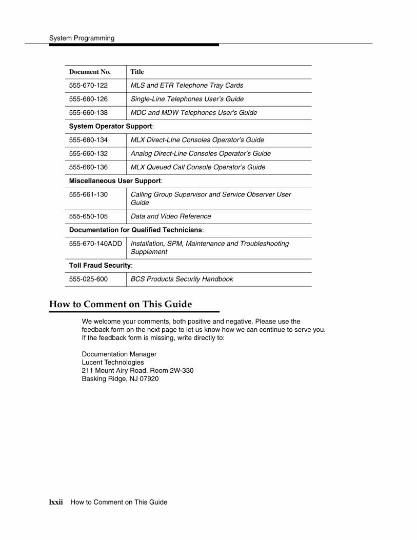
System Programming
lxxii How to Comment on This Guide
����������� ������������ 0
We welcome your comments, both positive and negative. Please use the feedback form on the next page to let us know how we can continue to serve you. If the feedback form is missing, write directly to:
Documentation ManagerLucent Technologies211 Mount Airy Road, Room 2W-330Basking Ridge, NJ 07920
555-670-122 MLS and ETR Telephone Tray Cards
555-660-126 Single-Line Telephones User’s Guide
555-660-138 MDC and MDW Telephones User's Guide
System Operator Support:
555-660-134 MLX Direct-LIne Consoles Operator’s Guide
555-660-132 Analog Direct-Line Consoles Operator’s Guide
555-660-136 MLX Queued Call Console Operator’s Guide
Miscellaneous User Support:
555-661-130 Calling Group Supervisor and Service Observer User Guide
555-650-105 Data and Video Reference
Documentation for Qualified Technicians:
555-670-140ADD Installation, SPM, Maintenance and Troubleshooting Supplement
Toll Fraud Security:
555-025-600 BCS Products Security Handbook
Document No. Title
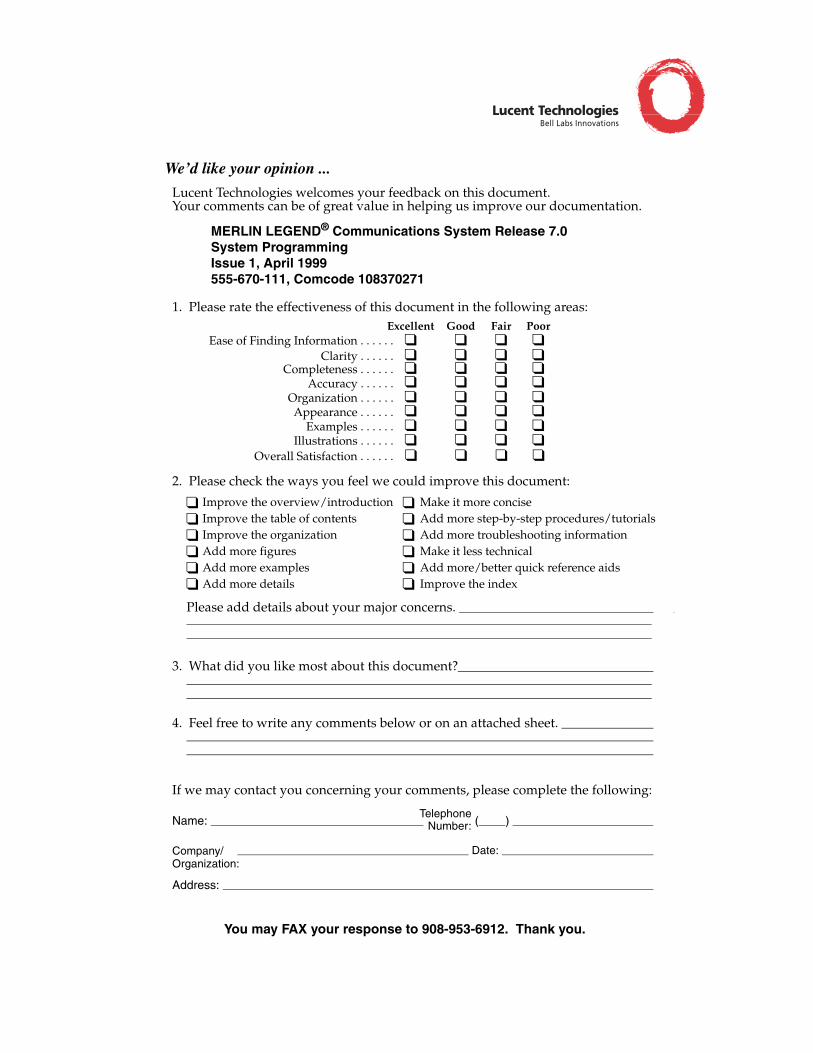
Name: ��������������������������������������������������������������������������������Telephone
Number:
Company/Organization:
Address: �������������������������������������������������������������������������������������������������������������������������������������������������������������������
You may FAX your response to 908-953-6912. Thank you.
Bell Labs InnovationsLucent Technologies
MERLIN LEGEND® Communications System Release 7.0System ProgrammingIssue 1, April 1999555-670-111, Comcode 108370271
We’d like your opinion ...
������������� ��������������������������� ������������������������������������������� ����� ������ ������������������ ��
�� ������������������������������������ ������� ����������
�
�
�
�
�
�
�
�
�
�
�
�
�������������� �� ������� �
�������������������������
�������������� !�� �
"�������� �����
"��������#������
"����������� ��
$���� ��������� ��
"�����������%��%�������������� ���� ���
"��������������� ��� ������ �
$���� ����������� ���
"������ �������&� �������������� ��
���������� ���#
��������������� ��������������'������������������������������������������������������������������������������������������������������������������������������������������������������������������������������������������������������������������������������������������������������������������
�������������������������������������������������������������������������������������������������������������������������������������������������������������������������������
(� )���� ������ ������������� ���������*���������������������������������������������������������������������������������������������������������������������������������������������������������������������������������������������������������������������������������������������������������������������������������������������������������������������������������������������������
������������������������������������������������������������������������������������������������������������������������������������������������������������������������������������������������������������������������������������������������������������������������������������������
+� ,������������� ���������������������������������������������������������������������
�������������������������� ��������������-����������������������� ���
(����������) �����������������������������������������������������
��������������������������������������������������������������������������������������� Date: �����������������������������������������������������������
.������, �� ���������� �������������
/��� ��������������/����������������������
"�������������������0���� !�� �������������"���������������������.#������������������
��������� ��������������
0�������1�� ����� �������������
��������� � �� � ��
�
���
��
�
�
2� ��������������������� ���������� ���������� ��������� ���������
�
���
��
�
�
�
���
��
�
�
�
���
��
�
�
����

��������
1-i
1�������� �����
�������� 1-1
������������ �� ������ �������� 1-2
� Planning Forms 1-2
� Types of Programming 1-3
������ �������� ������� 1-4
� Console Components 1-5
� Console Buttons 1-6
Fixed Display Buttons 1-7
Unlabeled Display Buttons 1-7
� Console Overlay 1-8
� Console and DSS Lights 1-9
Console Lights 1-9
DSS Lights 1-9
�������� ���������� 1-10
� Procedure Organization 1-10
� Procedure Contents 1-10
� Programming Screens 1-11
� Verifying Data Entry 1-13
� Saving Entries and Moving among Screens 1-14
� Using Enter 1-16
� Using Next 1-16
� System Programming Hierarchy 1-17

1-ii
��������
System Programming
������ �� ������ ������������ ��� ���� !� ������� 1-43
� System Programming Menu 1-44
Exiting System Programming 1-45
���� ����� 1-45
� System Forced Idle 1-46
� Line or Trunk Idle 1-47
� Extension Forced Idle 1-47
� 100D Module Idle 1-48
� Forced Idle Reminder Tones 1-48
Overview 1-1
1Programming Basics 1
Overview 1
This chapter presents the information you need to master before you begin the programming procedures covered in Chapter 3, ‘‘Programming Procedures.” It covers the following subjects:
� An introduction to system programming basics
� How to use the system programming console
� How the programming screens and keys work
� How to interpret and use the programming procedures
� How to enter and exit system programming
� Which system components require idle states for programming
System Programming
1-2 Introduction to System Programming
Introduction to System Programming 1
The communications system offers easy-to-use, menu-driven software for system programming. After your system is installed, use this software to accommodate your company’s changing needs for such enhancements and modifications as upgraded lines, additional modules, and new extension programming.
Planning Forms 1
Before you begin to program or modify your communications system, you should familiarize yourself with the system planning forms. Initially, system planning forms are used to plan your communications system and program your system during installation. After installation, they remain a source for all programming information on your communications system database. The information ranges from the system time and date to specific equipment configurations and feature programming.
Each planning form is either required or optional:
� Required forms are necessary to program the system.
� Optional forms are needed only if the system manager included the features or options shown on the forms.
Before you begin to program or modify your system, review the Control Unit Diagram on system planning Form 1 to identify the module types installed in the system’s control unit. Use this information to program or modify lines and trunks and assign or reassign lines to extensions. Check the physical control unit to verify that the modules are placed in the slots identified on the diagram. Correct the diagram on Form 1 if there are any discrepancies.
Before you make any changes to your system, be sure to do the following:
� Mark any system modifications or changes on the appropriate planning form. Keep your planning forms up-to-date.
� Check the Feature Reference for possible feature interactions.
� Program the system or the system component during the appropriate idle state. See ‘‘Idle States’’ on page 1-45.
Programming Basics
Introduction to System Programming 1-3
Types of Programming 1
The three types of programming available for the communications system are:
� System Programming. This type of programming enables the system manager to program features that affect all or most system users, and requires one of the following:
— An MLX-20L telephone connected to one of the first five jacks of the first MLX module in the control unit.
— A PC with System Programming and Maintenance (SPM) software. SPM emulates a system programming console on your PC.The PC should be connected to the lower port (labeled ADMIN) on the processor module. A PC with a modem can perform system programming remotely through the public network, or by connecting to a tip/ring extension jack (012 (T/R), 016 (T/R), or 008 OPT module) on the communications system. A built-in modem in the processor allows the PC and the communications system to communicate.
� Extension Programming. This type of programming enables individual extension users and system operators (except for Queued Call Console operators) to change their extension features to meet individual needs. For details about extension programming, see the appropriate user and operator guides.
� Centralized Telephone Programming. This type of programming enables the system manager to program any feature that can be programmed by individual extension users or system operators. Some features can be programmed only in centralized telephone programming. Centralized telephone programming can be done on the programming console or on a PC with the SPM software. See Chapter 4, ‘‘Centralized Telephone Programming.”
� If your system has the Integrated Solution II1 or Integrated Solution III1 (IS II/III) UNIX® application, see Chapter 2, ‘‘Programming with SPM” for a list of the appropriate documentation.
1 Can no longer be ordered.
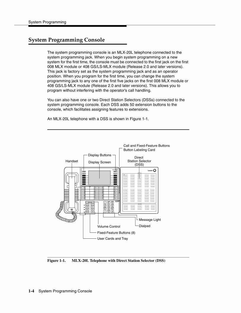
System Programming
1-4 System Programming Console
System Programming Console 1
The system programming console is an MLX-20L telephone connected to the system programming jack. When you begin system programming on a new system for the first time, the console must be connected to the first jack on the first 008 MLX module or 408 GS/LS-MLX module (Release 2.0 and later versions). This jack is factory set as the system programming jack and as an operator position. When you program for the first time, you can change the system programming jack to any one of the first five jacks on the first 008 MLX module or 408 GS/LS-MLX module (Release 2.0 and later versions). This allows you to program without interfering with the operator’s call handling.
You can also have one or two Direct Station Selectors (DSSs) connected to the system programming console. Each DSS adds 50 extension buttons to the console, which facilitates assigning features to extensions.
An MLX-20L telephone with a DSS is shown in Figure 1-1.
Figure 1-1. MLX-20L Telephone with Direct Station Selector (DSS)
ABC DEF
GHI JKL MNO
PQRS TUV WXYZ
OPER
1 2 3
4 5 6
7 8 9
0 #*
Direct Station Selector
(DSS)
Display Buttons
Display ScreenHandset
Volume
vvFeature
HFAI
Mute
Speaker Hold
Drop
Conf
Transfer
Home
Menu
More
Inspct00
Message Light
Volume Control
User Cards and Tray
Fixed-Feature Buttons (8)
Dialpad
Call and Fixed-Feature ButtonsButton Labeling Card
MLX-20L
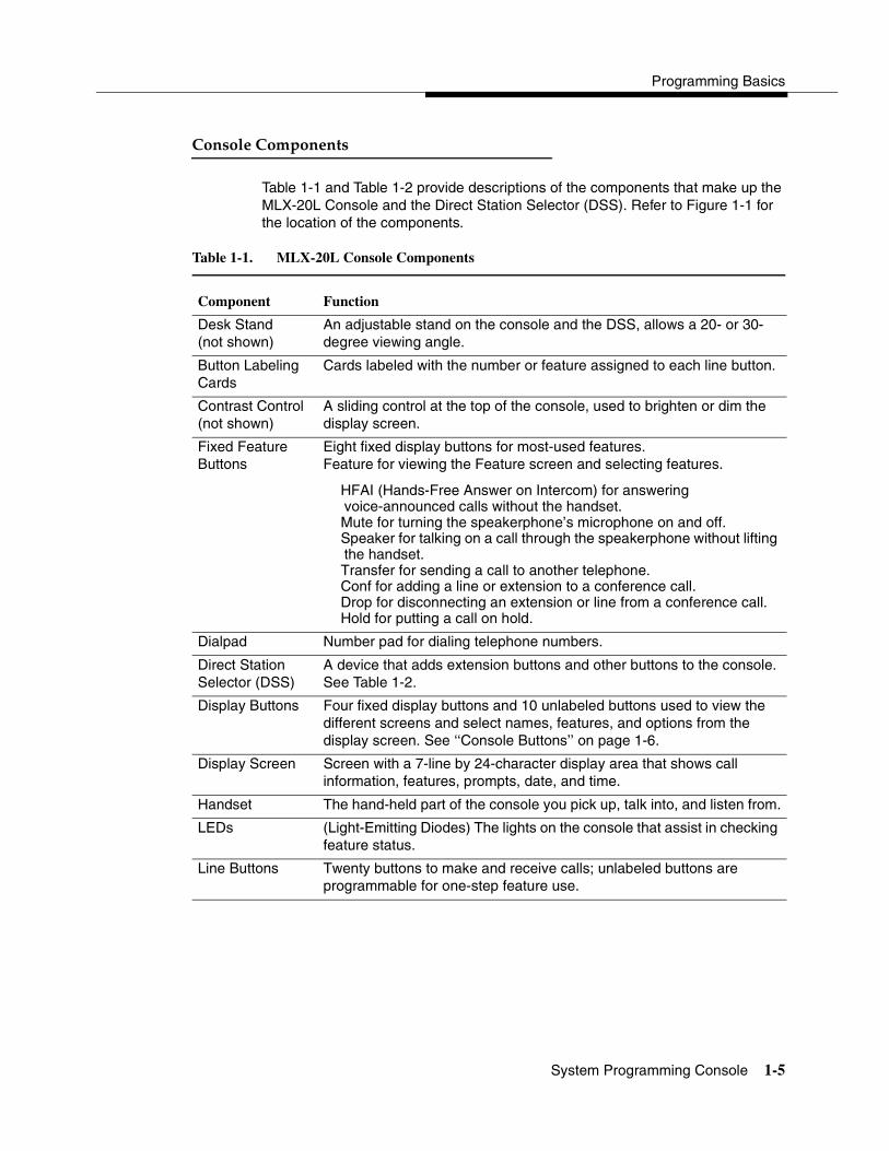
Programming Basics
System Programming Console 1-5
Console Components 1
Table 1-1 and Table 1-2 provide descriptions of the components that make up the MLX-20L Console and the Direct Station Selector (DSS). Refer to Figure 1-1 for the location of the components.
Table 1-1. MLX-20L Console Components
Component Function
Desk Stand(not shown)
An adjustable stand on the console and the DSS, allows a 20- or 30-degree viewing angle.
Button Labeling Cards
Cards labeled with the number or feature assigned to each line button.
Contrast Control(not shown)
A sliding control at the top of the console, used to brighten or dim the display screen.
Fixed Feature Buttons
Eight fixed display buttons for most-used features.Feature for viewing the Feature screen and selecting features.
HFAI (Hands-Free Answer on Intercom) for answering voice-announced calls without the handset.Mute for turning the speakerphone’s microphone on and off.Speaker for talking on a call through the speakerphone without lifting the handset.Transfer for sending a call to another telephone.Conf for adding a line or extension to a conference call.Drop for disconnecting an extension or line from a conference call.Hold for putting a call on hold.
Dialpad Number pad for dialing telephone numbers.
Direct Station Selector (DSS)
A device that adds extension buttons and other buttons to the console. See Table 1-2.
Display Buttons Four fixed display buttons and 10 unlabeled buttons used to view the different screens and select names, features, and options from the display screen. See ‘‘Console Buttons’’ on page 1-6.
Display Screen Screen with a 7-line by 24-character display area that shows call information, features, prompts, date, and time.
Handset The hand-held part of the console you pick up, talk into, and listen from.
LEDs (Light-Emitting Diodes) The lights on the console that assist in checking feature status.
Line Buttons Twenty buttons to make and receive calls; unlabeled buttons are programmable for one-step feature use.

System Programming
1-6 System Programming Console
Console Buttons 1
Use the 14 buttons located on either side of the MLX-20L console display area for system programming. These buttons are arranged in two columns of seven buttons, as shown in Figure 1-2.
Component Function
Message Light A red light that signals a waiting message.
User Cards and Tray
A slide-out drawer with erasable cards for noting telephone numbers and feature codes.
Volume Control A button for adjusting the volume of the speaker, handset, headset, and ringer.
Table 1-2. Direct Station Selector (DSS) Components
Component FunctionCovers Removable plastic covers to protect the designation cards. The top
cover protects the 50 DSS button labels. The lower cover fits over the fixed buttons.
DSS Designation Cards
Cards for labeling the extension or feature assigned to each button.
DSS Buttons Fifty buttons used for one-touch dialing of co-workers’ extensions to make or transfer calls. DSS buttons are also used to page co-workers over speakerphones, to park calls, and to handle outside calls.
Fixed Buttons Ten additional buttons, including Message Status, Direct Voice Mail, and three Page buttons. The five remaining buttons on the first DSS are not used. If a second DSS is connected to the console, the 10 buttons at the bottom of the second DSS are not used.
Fixed Message Status button used with fixed Page buttons to see which telephones have Message Lights on.
Fixed Page Buttons are three buttons used to select the pages of extensions that the 50 DSS buttons represent.
LEDs (Light-Emitting Diodes)
The lights that assist in checking feature status.
Table 1-1. MLX-20L Console Components—Continued
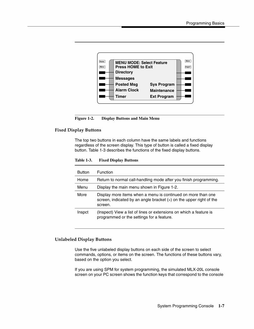
Programming Basics
System Programming Console 1-7
Figure 1-2. Display Buttons and Main Menu
Fixed Display Buttons 1
The top two buttons in each column have the same labels and functions regardless of the screen display. This type of button is called a fixed display button. Table 1-3 describes the functions of the fixed display buttons.
Unlabeled Display Buttons 1
Use the five unlabeled display buttons on each side of the screen to select commands, options, or items on the screen. The functions of these buttons vary, based on the option you select.
If you are using SPM for system programming, the simulated MLX-20L console screen on your PC screen shows the function keys that correspond to the console
Table 1-3. Fixed Display Buttons
Button Function
Home Return to normal call-handling mode after you finish programming.
Menu Display the main menu shown in Figure 1-2.
More Display more items when a menu is continued on more than one screen, indicated by an angle bracket (>) on the upper right of the screen.
Inspct (Inspect) View a list of lines or extensions on which a feature is programmed or the settings for a feature.
Home
Menu
More
Inspct
MENU MODE: Select FeaturePress HOME to ExitDirectory
Messages
Posted MsgAlarm Clock
Timer Ext Program
Maintenance
Sys Program
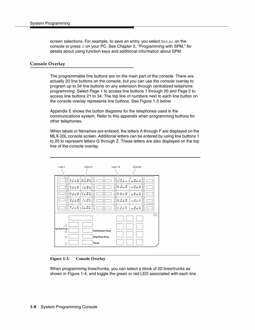
System Programming
1-8 System Programming Console
screen selections. For example, to save an entry, you select Enter on the console or press 0 on your PC. See Chapter 2, ‘‘Programming with SPM,” for details about using function keys and additional information about SPM.
Console Overlay 1
The programmable line buttons are on the main part of the console. There are actually 20 line buttons on the console, but you can use the console overlay to program up to 34 line buttons on any extension through centralized telephone programming. Select Page 1 to access line buttons 1 through 20 and Page 2 to access line buttons 21 to 34. The top line of numbers next to each line button on the console overlay represents line buttons. See Figure 1-3 below.
Appendix E shows the button diagrams for the telephones used in the communications system. Refer to this appendix when programming buttons for other telephones.
When labels or filenames are entered, the letters A through F are displayed on the MLX-20L console screen. Additional letters can be entered by using line buttons 1 to 20 to represent letters G through Z. These letters are also displayed on the top line of the console overlay.
Figure 1-3. Console Overlay
When programming lines/trunks, you can select a block of 20 lines/trunks as shown in Figure 1-4, and toggle the green or red LED associated with each line
G5 25 45 65
K4 24 44 64
O3 23 43 63
S2 22 42 62
W1 21 41 61
1O 30 50 70 H
9 29 49 69L
8 28 48 68P
7 27 47 67T
6 26 46 66X
I15 35 55 75
M14 34 54 74
Q13 33 53 73
U12 32 52 72
Y11 31 51 71
20 40 60 80J
19 39 59 79N
18 38 58 78R
17 37 57 77V
16 36 56 76Z
Top Sys Prog
Stop/Drop Entry
Pause
Switchhook Flash
5 / 25
4 / 24
3 / 23
2 / 22
1 / 21
10 / 30
9 / 29
8 / 28
7 / 27
6 / 26
15 20
14 / 34 19
13 / 33 18
12 / 32 17
11 / 31 16
/ /
/
/
/
/
Line 1 Line 21 Line 14 Line 34
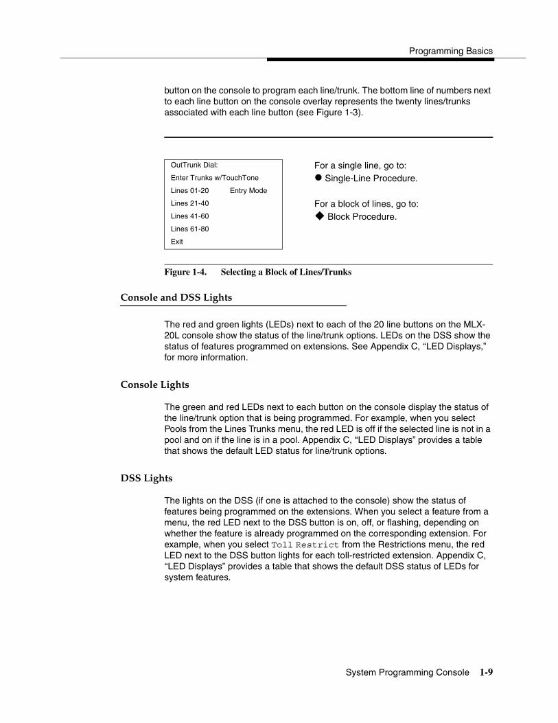
Programming Basics
System Programming Console 1-9
button on the console to program each line/trunk. The bottom line of numbers next to each line button on the console overlay represents the twenty lines/trunks associated with each line button (see Figure 1-3).
Figure 1-4. Selecting a Block of Lines/Trunks
Console and DSS Lights 1
The red and green lights (LEDs) next to each of the 20 line buttons on the MLX-20L console show the status of the line/trunk options. LEDs on the DSS show the status of features programmed on extensions. See Appendix C, ‘‘LED Displays,” for more information.
Console Lights 1
The green and red LEDs next to each button on the console display the status of the line/trunk option that is being programmed. For example, when you select Pools from the Lines Trunks menu, the red LED is off if the selected line is not in a pool and on if the line is in a pool. Appendix C, ‘‘LED Displays” provides a table that shows the default LED status for line/trunk options.
DSS Lights 1
The lights on the DSS (if one is attached to the console) show the status of features being programmed on the extensions. When you select a feature from a menu, the red LED next to the DSS button is on, off, or flashing, depending on whether the feature is already programmed on the corresponding extension. For example, when you select Toll Restrict from the Restrictions menu, the red LED next to the DSS button lights for each toll-restricted extension. Appendix C, ‘‘LED Displays” provides a table that shows the default DSS status of LEDs for system features.
OutTrunk Dial: For a single line, go to:Enter Trunks w/TouchTone � Single-Line Procedure.Lines 01-20 Entry Mode
Lines 21-40 For a block of lines, go to:Lines 41-60 � Block Procedure.Lines 61-80
Exit
System Programming
1-10 Programming Procedures
Programming Procedures 1
The programming procedures provide step-by-step instructions for programming the communications system. This section details how to make the best use of the programming procedures.
Procedure Organization 1
The programming procedures in Chapter 3, ‘‘Programming Procedures,” are organized into logical groups. The programming procedures associated with a specific aspect of the system are grouped together under one heading. For example, to assign network services for PRI, you would go to the section titled ‘‘PRI Facilities’’ and then locate the network services procedure. For quick reference, see ‘‘System Programming Hierarchy’’ on page 1-17 for a list of procedures based on the menu hierarchy in Appendix B. It traces the menu path for a specific function.
Procedure Contents 1
Each procedure begins with a general description of the feature, followed by a summary of programming information that includes the items listed below:
Programmable by Indicates who has permission to use the procedure.
Mode Specifies which system mode supports the procedure: Key, Hybrid/PBX, Behind Switch, or a combination.
Idle condition Specifies the idle state required before the procedure can be performed.
Planning form Indicates the planning forms that provide information for the procedure.
Factory setting Shows the factory settings, if any, for equipment or features affected by the procedure.
Valid entries Specifies the characters, numbers, or values accepted during data entry.
Inspect Specifies whether or not the feature status can be verified using the Inspect feature.
Copy option Indicates whether or not the feature can be copied to another system component once it has been programmed.
Console Procedure Provides a summary of the procedure steps using the system console.
PC Procedure Provides a summary of the procedure steps using SPM.

Programming Basics
Programming Procedures 1-11
In the unabridged, or expanded, version of System Programming, available on CD-Rom, step-by-step procedures, including screen displays, for programming the feature are provided after the summary version of the procedure. In addition, in Chapter 1 of the unabridged version of System Programming, a section entitled “Using the Programming Procedures” provides information about how to use the expanded version of the programming procedures.
Programming Screens 1
There are three types of system programming screens:
� Information Screens. To view what is currently programmed on the system.
� Menu selection screens. To select options from a menu.
� Data entry screens. To enter values or to identify a specific extension or line/trunk you want to program.
Figure 1-5 shows a sample information screen. When you select Sys Program from the main menu screen (shown in Figure 1-2 on page 1-7), the screen shown in Figure 1-5 appears with system setup information.
Figure 1-5. Information Screen
You cannot make changes on an information screen. Select Exit (or � on the PC) to continue to the next screen in the procedure.
System Set-up Your system information appears inReview and Exit place of the x’s. Size: xxxx
Type: xxxx
Operator: xxxx xxxx xxxx xxxx xxxx xxxx
Exit

System Programming
1-12 Programming Procedures
Figure 1-6 shows a sample menu selection screen.
Figure 1-6. Menu Selection Screen
A menu selection screen prompts you to select one of the available options. The screen title is the first line on all screens. The second line contains a system prompt or instruction. The remaining lines of text vary, based on the selected option.
An angle bracket (>) appears in the upper right corner of menu selection screens that have additional option screens. Press More (or � on the PC) to see the additional screens. Continue to press More to move through the screens and return to the original screen.
Figure 1-7 shows a sample data entry screen.
Figure 1-7. Data Entry Screen
A data entry screen prompts you to enter specific data or to make specific choices. Data to be entered will be displayed with n’s in the text. When n’s appear on the data entry screen they indicate data currently programmed for the feature.
System Programming: > Screen title and More indicator (>)Make a Selection PromptSystem Extensions Options ListSysRenumber Options
Operator Tables
LinesTrunks AuxEquip
Exit NightSrvce
Assign Lines/Trunks: Selected OptionEnter extension Prompt
Data Entry Area
Backspace
Exit Enter
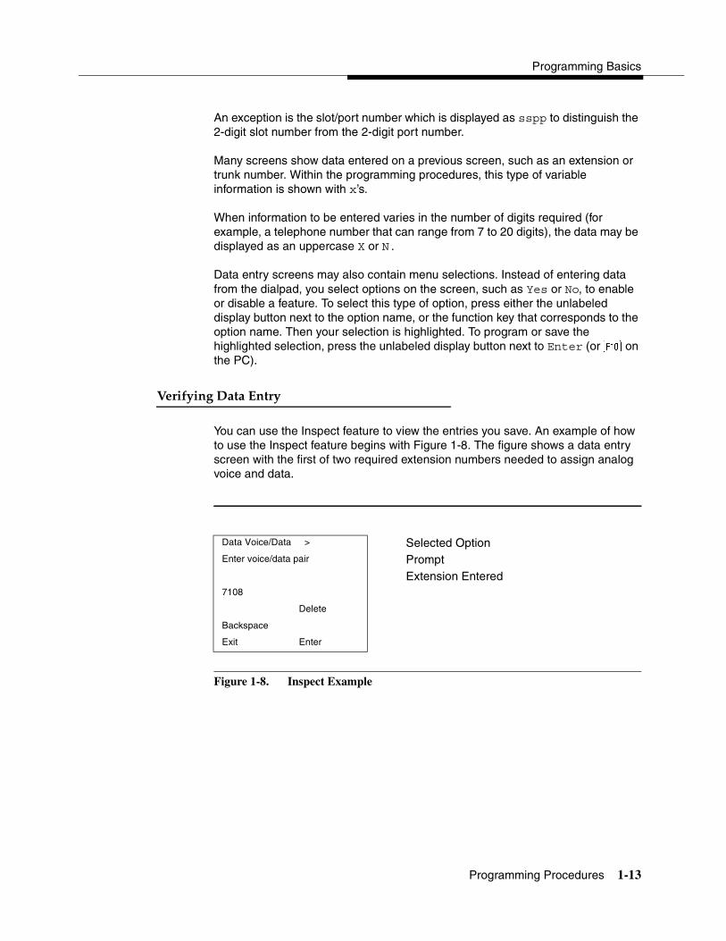
Programming Basics
Programming Procedures 1-13
An exception is the slot/port number which is displayed as sspp to distinguish the 2-digit slot number from the 2-digit port number.
Many screens show data entered on a previous screen, such as an extension or trunk number. Within the programming procedures, this type of variable information is shown with x’s.
When information to be entered varies in the number of digits required (for example, a telephone number that can range from 7 to 20 digits), the data may be displayed as an uppercase X or N.
Data entry screens may also contain menu selections. Instead of entering data from the dialpad, you select options on the screen, such as Yes or No, to enable or disable a feature. To select this type of option, press either the unlabeled display button next to the option name, or the function key that corresponds to the option name. Then your selection is highlighted. To program or save the highlighted selection, press the unlabeled display button next to Enter (or � on the PC).
Verifying Data Entry 1
You can use the Inspect feature to view the entries you save. An example of how to use the Inspect feature begins with Figure 1-8. The figure shows a data entry screen with the first of two required extension numbers needed to assign analog voice and data.
Figure 1-8. Inspect Example
Data Voice/Data > Selected OptionEnter voice/data pair Prompt
Extension Entered7108
Delete
Backspace
Exit Enter

System Programming
1-14 Programming Procedures
After you enter and save 7108, the system automatically assigns the next sequential extension jack number. This extension jack pair does not appear on the data entry screen; however, if you press Inspct (� on the PC), the pair appears, as shown on the sample Inspect screen in Figure 1-9.
Figure 1-9. Sample Inspect Screen
Whenever you want to return to the previous screen, select Exit (� on the PC).
The Inspect feature also allows you to check a value currently programmed for a feature. This is helpful when you are changing or modifying features. You can also use it when you program sequential extensions or lines to verify the last number programmed. See the Feature Reference for details about the Inspect feature.
Saving Entries and Moving among Screens 1
At the bottom of each screen, one or more screen keys may appear representing functions that allow you to change your entry, save your entry, or return to a previous screen. Various combinations of these screen keys appear on each programming screen. Figure 1-10 shows the QCC Priority screen with a typical display of screen keys.
Voice/Data Pairs: >
7108 7109 Inspect Data Displayed
Exit

Programming Basics
Programming Procedures 1-15
Figure 1-10. Screen Keys
The PC keys that correspond to the screen key selections are shown here for quick reference. These PC keys do not appear on the console display screen.
Table 1-4 contains details on the use of the screen keys.
QCC Priority x: x = QCC Priority entered in earlier stepEnter line/trunk number
xxx xxx = line/trunk number (801–880)Delete �
� Backspace Next � � Exit Enter �
Table 1-4. Screen Keys
Display PC Key Function
BackSpace � or �
Change your entry. Select Backspace (� or � on the PC) to correct your entry. Each time you press the key, the screen cursor moves backward to erase one character at a time.
Enter � or
Save your entry. Typically, you select Enter (� or on the PC) to complete a procedure and save the information. Occasionally, you must select Exit (� on the PC) and return to a previous screen after you use Enter. If the entry is not valid, the system may beep and/or display an error message and does not save the entry.
Delete � Delete a current entry. Select Delete �
Next � Program sequentially numbered items. If you are programming a group of sequentially numbered extensions, lines, or trunks, you may optionally select Next (� on the PC). This saves your entry and automatically provides the number of the next extension or trunk in the sequence. Typically, you remain at the same screen until you select Next. In a few cases, you may return to an earlier screen in the procedure.
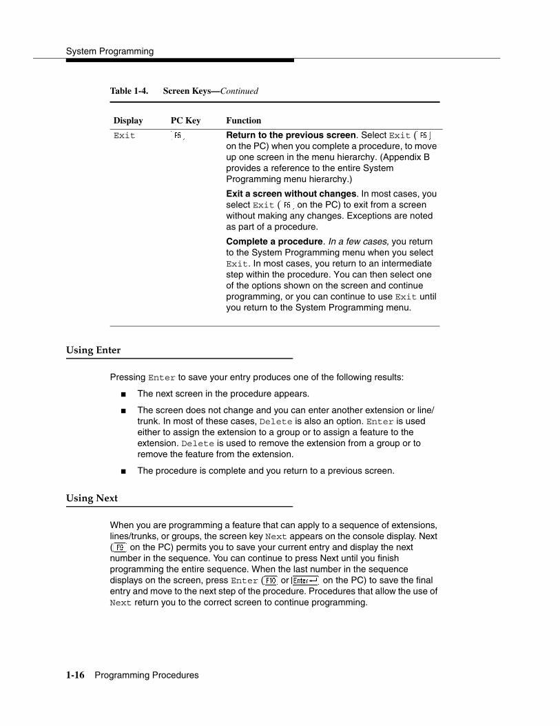
System Programming
1-16 Programming Procedures
Using Enter 1
Pressing Enter to save your entry produces one of the following results:
� The next screen in the procedure appears.
� The screen does not change and you can enter another extension or line/trunk. In most of these cases, Delete is also an option. Enter is used either to assign the extension to a group or to assign a feature to the extension. Delete is used to remove the extension from a group or to remove the feature from the extension.
� The procedure is complete and you return to a previous screen.
Using Next 1
When you are programming a feature that can apply to a sequence of extensions, lines/trunks, or groups, the screen key Next appears on the console display. Next (� on the PC) permits you to save your current entry and display the next number in the sequence. You can continue to press Next until you finish programming the entire sequence. When the last number in the sequence displays on the screen, press Enter (� or on the PC) to save the final entry and move to the next step of the procedure. Procedures that allow the use of Next return you to the correct screen to continue programming.
Display PC Key Function
Exit � Return to the previous screen. Select Exit (� on the PC) when you complete a procedure, to move up one screen in the menu hierarchy. (Appendix B provides a reference to the entire System Programming menu hierarchy.)
Exit a screen without changes. In most cases, you select Exit (� on the PC) to exit from a screen without making any changes. Exceptions are noted as part of a procedure.
Complete a procedure. In a few cases, you return to the System Programming menu when you select Exit. In most cases, you return to an intermediate step within the procedure. You can then select one of the options shown on the screen and continue programming, or you can continue to use Exit until you return to the System Programming menu.
Table 1-4. Screen Keys—Continued

Programming Basics
Programming Procedures 1-17
System Programming Hierarchy 1
The following table shows all of the options that are available under each of the System Programming main menu options displayed on the system programming console. A brief description of the option and the page number where detailed instructions can be found follow the option name.
Main menu options are shown in a separate box. First-level options are bold; second-level options are preceded by an asterisk (*). The remaining levels are shown with increasing degrees of indentation.
Option Description Page
System
Restart Restart the system (cold start) 3-2
SProg Port Extension used for system programming 3-3
Mode Sets the system mode. 3-5
* Key
* Hybrid/PBX
* BehindSwitch
Board Renum Renumber boards that are already installed 3-5
MaintenBusy Enable Automatic Maintenance Busy 3-6
* Enable
- Auto Busy TieTrunks
- Enable
- Disable
* Disable Disable Automatic Maintenance Busy
Date System date 3-8
Time System time 3-9
Back/Restore
* Backup Back up system programming to a Memory Card 3-236
* Restore Restore system programming from a Memory Card 3-236
* Auto Backup Automatic backup 3-237
- Off Turn off automatic backups
- Daily Daily backups of system programming
- Weekly Weekly backups of system programming

System Programming
1-18 Programming Procedures
Option Description Page
SysRenumber
Default Numbering Default extension numbering plans 3-10
* 2-Digit
* 3-Digit
* SetUp Space
Single Single extension renumbering 3-14
* Lines Lines/Trunks
* Extensions Extensions
* Pools Pools (Hybrid/PBX only)
* Group Page Paging Group
* GrpCalling Calling Group
* Adjuncts Adjuncts
* Park Park
* ARS DialOut Automatic Route Selection dial out (Hybrid/PBX only)
* RemoteAccs Remote Access
* DSS Buttons Page buttons on the DSS
* ListDirctNo Listed directory number
Block Block extension renumbering 3-15
* Lines
* Extensions
* Adjuncts
NonLocal UDPSpecify ranges of extensions on remote networked system
3-16

Programming Basics
Programming Procedures 1-19
Option Description Page
Operator
Positions System operator positions 3-21
* Direct Line Direct-Line Console (DLC) 3-24
* Queued Call Queued Call Console (QCC) 3-22
Queued Call QCC optional features (Hybrid/PBX mode 3-137
only)
* Hold Rtrn Hold Return 3-137
- Return to Queue
- Remain on Hold
* HoldRelease Automatic hold or release 3-138
- Auto Hold
- Auto Release
* Threshold Queue over threshold 3-139
* ElvatePrior Elevate priority 3-140
* InQue Alert Calls-In-Queue Alert 3-140
- InQue Alert Enable
- InQue Alert Disable
* Call Types QCC Operator to Receive Call Types 3-379
- Dial 0
- Priority
- Operator
- Follow/Frwd Forward/Follow Me Calls
- Unassign DID DID call to invalid destinations
- Priority
- Operator
- ListedNumber Calls to the Listed Directory Number
- Priority
- Operator
- QCC Ext QCC Extension calls
- Returning Returning calls

System Programming
1-20 Programming Procedures
Option Description Page
Operator Continued
- Priority
- Operator
- GrpCoverage Group Coverage calls
- Priority
- Operator
* Msg Center Message center operation 3-144
* ExtndComplt Extended call completion 3-145
- Automatic Complete
- Manual Complete
* Return Ring Return Ring 3-146
* QCC Backup Position Busy Backup 3-146
* Voice Annc Voice Announce for QCC 3-147
Hold Timer Systemwide hold timer for QCCs and
DLCs 3-136
DLC Hold DLC Operator Automatic Hold 3-136
* Auto Hold Enable
* Auto Hold Disable
Option Description Page
LinesTrunks Lines/Trunks options
LS/GS/DS1 Loop-start, ground-start or DS1 options
* (DS1) DS1 options
- Type Type of DS1 facility 3-45
- T1
- GroundStart Ground-start emulation on selected channels
- Loop Start Loop-start emulation on selected channels
- TIE Tie Trunk emulation on selected channels
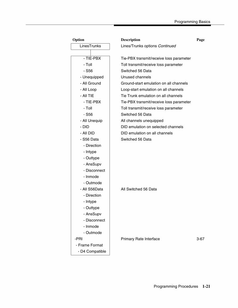
Programming Basics
Programming Procedures 1-21
Option Description Page
LinesTrunks Lines/Trunks options Continued
- TIE-PBX Tie-PBX transmit/receive loss parameter
- Toll Toll transmit/receive loss parameter
- S56 Switched 56 Data
- Unequipped Unused channels
- All Ground Ground-start emulation on all channels
- All Loop Loop-start emulation on all channels
- All TIE Tie Trunk emulation on all channels
- TIE-PBX Tie-PBX transmit/receive loss parameter
- Toll Toll transmit/receive loss parameter
- S56 Switched 56 Data
- All Unequip All channels unequipped
- DID DID emulation on selected channels
- All DID DID emulation on all channels
- S56 Data Switched 56 Data
- Direction
- Intype
- Outtype
- AnsSupv
- Disconnect
- Inmode
- Outmode
- All S56Data All Switched 56 Data
- Direction
- Intype
- Outtype
- AnsSupv
- Disconnect
- Inmode
- Outmode
-PRI Primary Rate Interface 3-67
- Frame Format
- D4 Compatible
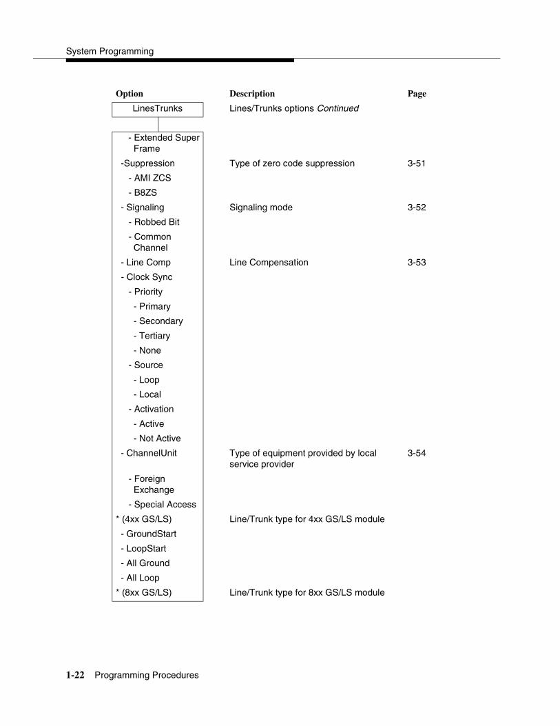
System Programming
1-22 Programming Procedures
Option Description Page
LinesTrunks Lines/Trunks options Continued
- Extended Super Frame
-Suppression Type of zero code suppression 3-51
- AMI ZCS
- B8ZS
- Signaling Signaling mode 3-52
- Robbed Bit
- Common Channel
- Line Comp Line Compensation 3-53
- Clock Sync
- Priority
- Primary
- Secondary
- Tertiary
- None
- Source
- Loop
- Local
- Activation
- Active
- Not Active
- ChannelUnit Type of equipment provided by local service provider
3-54
- Foreign Exchange
- Special Access
* (4xx GS/LS) Line/Trunk type for 4xx GS/LS module
- GroundStart
- LoopStart
- All Ground
- All Loop
* (8xx GS/LS) Line/Trunk type for 8xx GS/LS module

Programming Basics
Programming Procedures 1-23
Option Description Page
LinesTrunks Lines/Trunks options Continued
- GroundStart
- LoopStart
- All Ground
- All Loop
Tie Lines
* Direction Tie trunks direction
- Two Way
- OutGoing
- Incoming
* Intype Signaling type: incoming tie trunk
- Wink
- Delay
- Immed
- Auto
* Outtype Signaling type: outgoing tie trunk
- Wink
- Delay
- Immed
- Auto
* E&M Signal Type of tie trunk signal
- Type 1S
- Type 1C
- Type 5
* Inmode Set incoming tie trunk to touch-tone or rotary
* Outmode Set outgoing tie trunk to touch-tone or rotary
* Dialtone Tie trunk dial tone
* AnsSupvr Tie trunk answer supervision time
* Disconnect Tie trunk disconnect time
TT/LS Disc
* OutMode Outmode Signaling for loop- or ground-start trunks
3-27

System Programming
1-24 Programming Procedures
Option Description Page
LinesTrunks Lines/Trunks options Continued
* LS Disconnect Disconnect signaling reliability 3-30
- Yes
- No
DID DID Trunk Options 3-61
* Block Block assignment 3-61
* Type DID trunk type 3-62
- Immed
- Wink
* Disconnect DID trunk disconnect time 3-63
* ExpectDigit Expected digits 3-63
* DeleteDigit Delete digits 3-64
* Add Digits Add digits 3-65
* Signaling Type of dialing signal 3-65
- Rotary
- Touch Tone
* InvalDstn Directing outside calls on invalid extension 3-66
- Send To Backup Extension
- Return Fast Busy
PRI Primary Rate Interface (PRI) trunk options 3-67
* PhoneNumber Telephone number to each PRI channel 3-69
* B-ChannelGRP Assign B-channel groups 3-70
- Lines Assign lines to B-channel groups 3-70
- Network Serv Network service 3-72
- AT&T Toll AT&T toll service
- MegacomWATS
- ACCUNET SDS
- SoftDefNetw
- Megacom 800
- MULTIQUEST
- LongDistnce
- 5ESS Local Local service

Programming Basics
Programming Procedures 1-25
Option Description Page
LinesTrunks Lines/Trunks options Continued
- OUTWATS
- 56/64 Digit
- VirtPrivNet
- INWATS
- MCI Toll
- MCI PRISM
- MCI VNET
- MCI 800
- MCI 900
- DMS-100Local
- DMS-Private
- DMS- OUTWATS
- DMS-FX
- DMS-TieTrk
- Misc Miscellaneous network service
- Other
- CallByCall
- Legend UDP Private network tandem trunk
- ElectTandNwk
- Copy Number Copy telephone number to send 3-73
- Copy PhnNum to NumToSend
- Do Not CopyTelephone Number
- IncomingRtg Incoming Routing 3-74
- Routing by Dial Plan
- Route by Line Appearance
- Route Directly to UDP
* NumberToSend Telephone number to send to the network 3-75
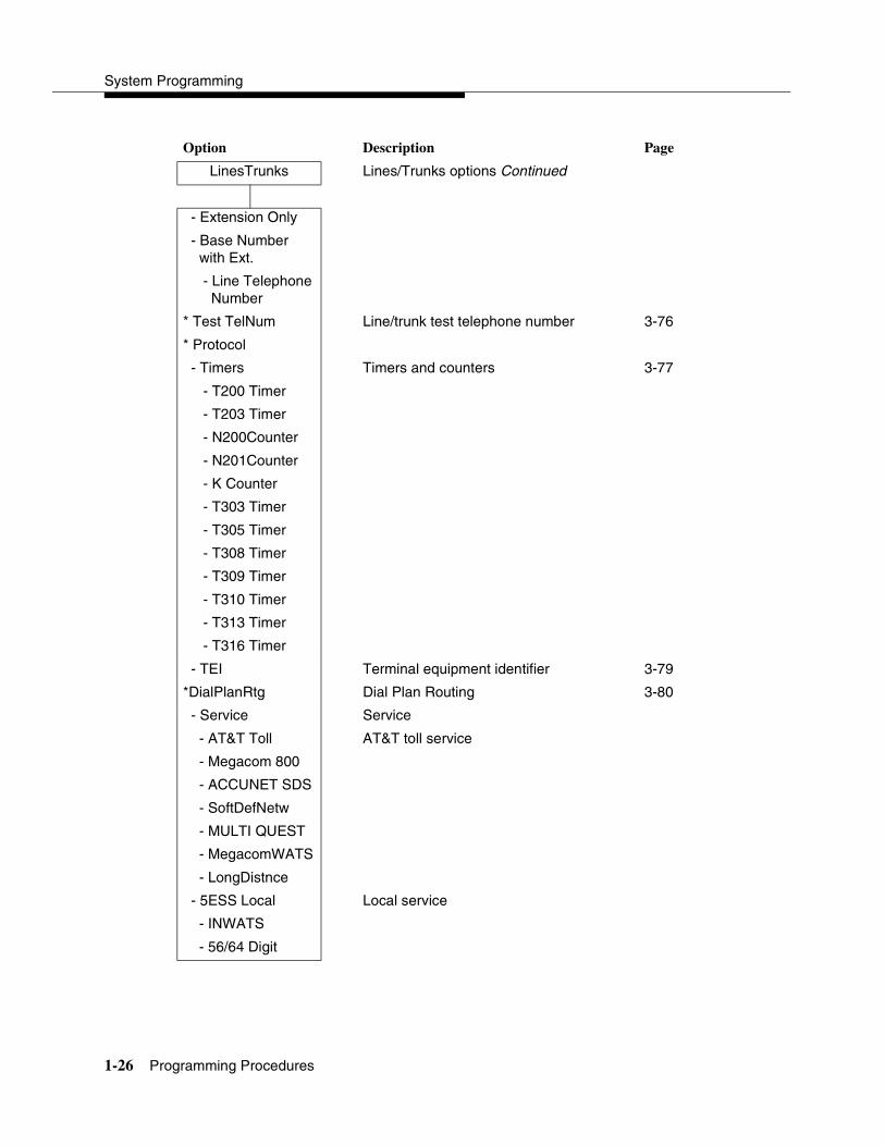
System Programming
1-26 Programming Procedures
Option Description Page
LinesTrunks Lines/Trunks options Continued
- Extension Only
- Base Numberwith Ext.
- Line Telephone Number
* Test TelNum Line/trunk test telephone number 3-76
* Protocol
- Timers Timers and counters 3-77
- T200 Timer
- T203 Timer
- N200Counter
- N201Counter
- K Counter
- T303 Timer
- T305 Timer
- T308 Timer
- T309 Timer
- T310 Timer
- T313 Timer
- T316 Timer
- TEI Terminal equipment identifier 3-79
*DialPlanRtg Dial Plan Routing 3-80
- Service Service
- AT&T Toll AT&T toll service
- Megacom 800
- ACCUNET SDS
- SoftDefNetw
- MULTI QUEST
- MegacomWATS
- LongDistnce
- 5ESS Local Local service
- INWATS
- 56/64 Digit
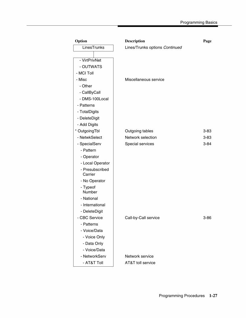
Programming Basics
Programming Procedures 1-27
Option Description Page
LinesTrunks Lines/Trunks options Continued
- VirtPrivNet
- OUTWATS
- MCI Toll
- Misc Miscellaneous service
- Other
- CallByCall
- DMS-100Local
- Patterns
- TotalDigits
- DeleteDigit
- Add Digits
* OutgoingTbl Outgoing tables 3-83
- NetwkSelect Network selection 3-83
- SpecialServ Special services 3-84
- Pattern
- Operator
- Local Operator
- Presubscribed Carrier
- No Operator
- Typeof Number
- National
- International
- DeleteDigit
- CBC Service Call-by-Call service 3-86
- Patterns
- Voice/Data
- Voice Only
- Data Only
- Voice/Data
- NetworkServ Network service
- AT&T Toll AT&T toll service

System Programming
1-28 Programming Procedures
Option Description Page
LinesTrunks Lines/Trunks options Continued
- Megacom WATS
- ACCUNET SDS
- SoftDefNetw
- LongDistnce
- MCI Toll
- MCI PRISM
- MCI VNET
- MCI 800
- MCI 900
- DMS-100Local
- DMS-Private
- DMS-OUTWATS
- DMS-FX
- DMS-TieTrk
- Local Local service
- OUTWATS
- 56/64 Digit
- VirtPrivNet
- Misc Miscellaneous service
- Other
- No Service
- Delete Digit Number of digits to delete
* Switch Type Type of switch at far end 3-68
- 4ESS
- 5ESS
- DMS-250
- DMS-100
- DES-600E
- Legend-NTWK For PRI tandem trunks

Programming Basics
Programming Procedures 1-29
Option Description Page
LinesTrunks Lines/Trunks options Continued
- Legend-PBX For PRI tandem trunks
Copy Copy options for lines/trunks 3-40
* Single
* Block
Remote Access Remote Access options
* LinesTrunks Remote Access trunk assignment 3-189
- Dedicated
- Shared
- No Remote
* Non-TIE Non-Tie Lines: Remote Access options
- BarrierCode Barrier code requirements
- Barrier Code Required
- BarrierCode Not Required
- Restriction Non-Tie trunk restriction
- Unrestricted
- Outward Restrict
- Toll Restrict
- ARS Restrict Non-Tie trunk ARS Facility Restriction Level
- Allow List Non-Tie trunk Allowed Lists assignment
- DisallowLst Non-Tie trunk Disallowed Lists assignment
* TIE Lines Tie lines: Remote Access options
- BarrierCode Barrier code requirements 3-195
- Barrier Code Required
- BarrierCode Not Required
- Restriction Tie trunk restriction
- Unrestricted
- Outward Restrict

System Programming
1-30 Programming Procedures
Option Description Page
LinesTrunks Lines/Trunks options Continued
- Toll Restrict
- ARS Restrict Tie and DID trunk ARS Facility Restriction Level
- Allow List Tie and DID trunk Allowed Lists assignment
- DisallowLst Tie and DID trunk Disallowed Lists assignment
* BarrierCode Barrier code options 3-193
- SProg/Maint Not currently available
- Code Info Barrier code information
- Code Length Barrier code length
- Code Entry Barrier code assignment
- Restriction Remote Access with barrier code: restrictions
- Unrestricted
- Outward Restrict
- Toll Restrict
- ARS Restrict Remote Access with barrier code: ARS Restriction
- Allow List Remote Access with barrier code: Allowed Lists
- DisallowLst Remote Access with barrier code: Disallowed Lists
* AutoQueuing Automatic Callback on busy pools or extensions
3-190
- Enable
- Disable
Pools Trunk to Pools assignment 3-38
Toll Type Toll prefix (1 or 0) requirement 3-31
HoldDiscnct Hold disconnect interval 3-32
PrncipalUsr Principal user for personal line 3-33
QCC Prior QCC queue priority level 3-34
QCC Oper QCC operator to receive calls 3-35
LS-ID Delay LS-ID delay for 800 LS-ID module 3-36
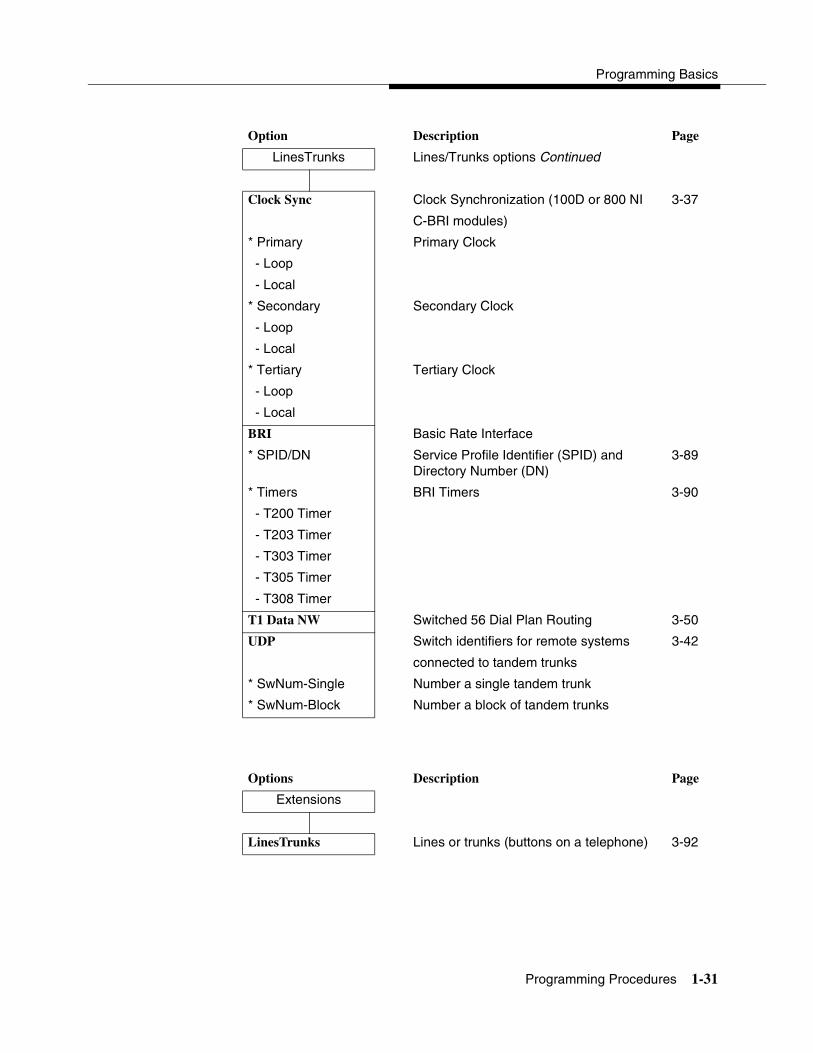
Programming Basics
Programming Procedures 1-31
Option Description Page
LinesTrunks Lines/Trunks options Continued
Clock Sync Clock Synchronization (100D or 800 NI 3-37
C-BRI modules)
* Primary Primary Clock
- Loop
- Local
* Secondary Secondary Clock
- Loop
- Local
* Tertiary Tertiary Clock
- Loop
- Local
BRI Basic Rate Interface
* SPID/DN Service Profile Identifier (SPID) and Directory Number (DN)
3-89
* Timers BRI Timers 3-90
- T200 Timer
- T203 Timer
- T303 Timer
- T305 Timer
- T308 Timer
T1 Data NW Switched 56 Dial Plan Routing 3-50
UDP Switch identifiers for remote systems 3-42
connected to tandem trunks
* SwNum-Single Number a single tandem trunk
* SwNum-Block Number a block of tandem trunks
Options Description Page
Extensions
LinesTrunks Lines or trunks (buttons on a telephone) 3-92

System Programming
1-32 Programming Procedures
Options Description Page
Extensions Continued
Line Copy Copy outside line/trunk options 3-95
* Single
* Block
Dial OutCd Pool dial-out code restrictions 3-119
Restriction Outward/toll restrictions 3-120
* Unrestricted
* Outward Restrict
* Toll Restrict
RestrctCopy Copy calling restrictions, Allowed Lists, and Disallowed
3-122
* Single Lists
* Block
Account Account code entry 3-124
BIS/HFAI Built-in Speakerphone/Hands-Free Answer on Intercom
3-102
Call PickUp Call pickup group 3-148
VoiceSign1 Assign voice pair to provide Voice Announce to Busy
3-102
Ext Status Extension status: hotel or Group Calling/CMS
3-174
Group Page Paging group members 3-149
Group Cover Coverage group members 3-150
Grp Calling Calling group members and options 3-155
* Hunt Type Hunt Type 3-155
- Circular
- Linear
- Most Idle
* DelayAnnce Group Calling delay announcement 3-156
- Primary
- Secondary
- Interval
- Repeat
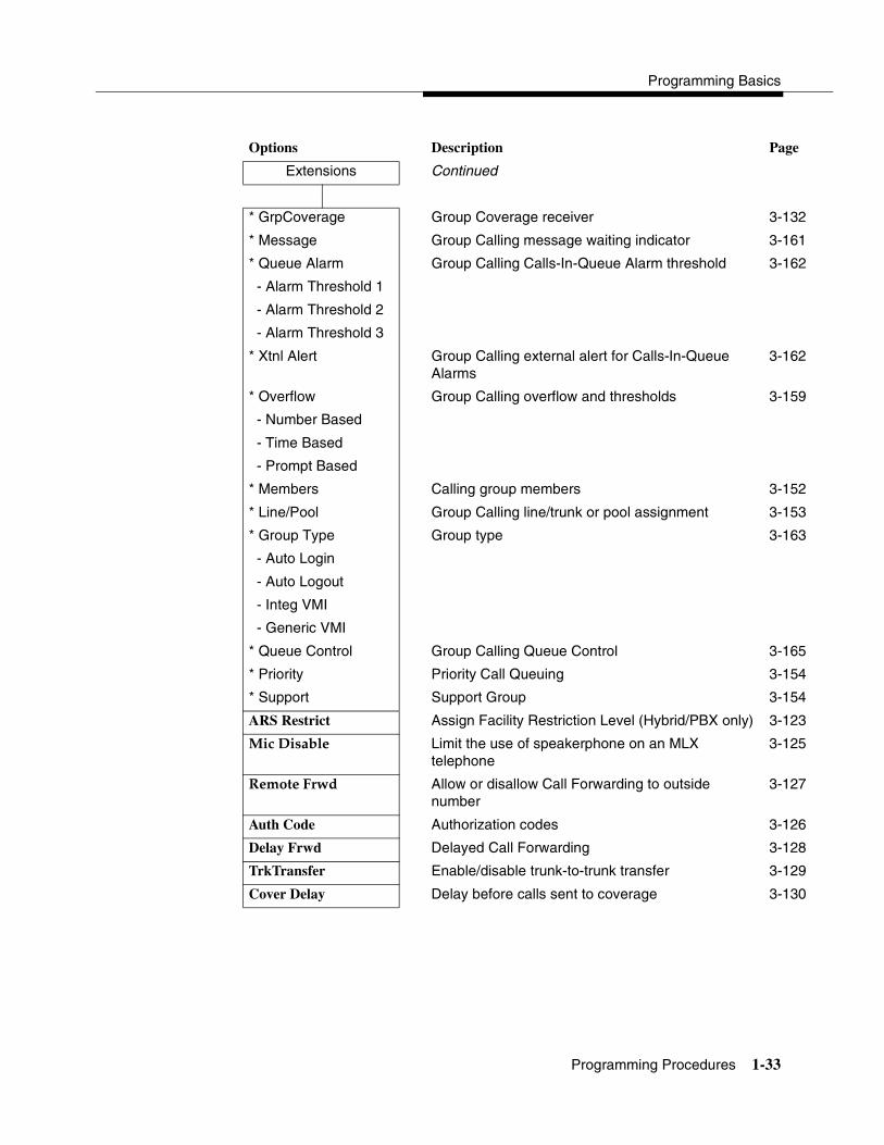
Programming Basics
Programming Procedures 1-33
Options Description Page
Extensions Continued
* GrpCoverage Group Coverage receiver 3-132
* Message Group Calling message waiting indicator 3-161
* Queue Alarm Group Calling Calls-In-Queue Alarm threshold 3-162
- Alarm Threshold 1
- Alarm Threshold 2
- Alarm Threshold 3
* Xtnl Alert Group Calling external alert for Calls-In-Queue Alarms
3-162
* Overflow Group Calling overflow and thresholds 3-159
- Number Based
- Time Based
- Prompt Based
* Members Calling group members 3-152
* Line/Pool Group Calling line/trunk or pool assignment 3-153
* Group Type Group type 3-163
- Auto Login
- Auto Logout
- Integ VMI
- Generic VMI
* Queue Control Group Calling Queue Control 3-165
* Priority Priority Call Queuing 3-154
* Support Support Group 3-154
ARS Restrict Assign Facility Restriction Level (Hybrid/PBX only) 3-123
Mic Disable Limit the use of speakerphone on an MLX telephone
3-125
Remote Frwd Allow or disallow Call Forwarding to outside number
3-127
Auth Code Authorization codes 3-126
Delay Frwd Delayed Call Forwarding 3-128
TrkTransfer Enable/disable trunk-to-trunk transfer 3-129
Cover Delay Delay before calls sent to coverage 3-130
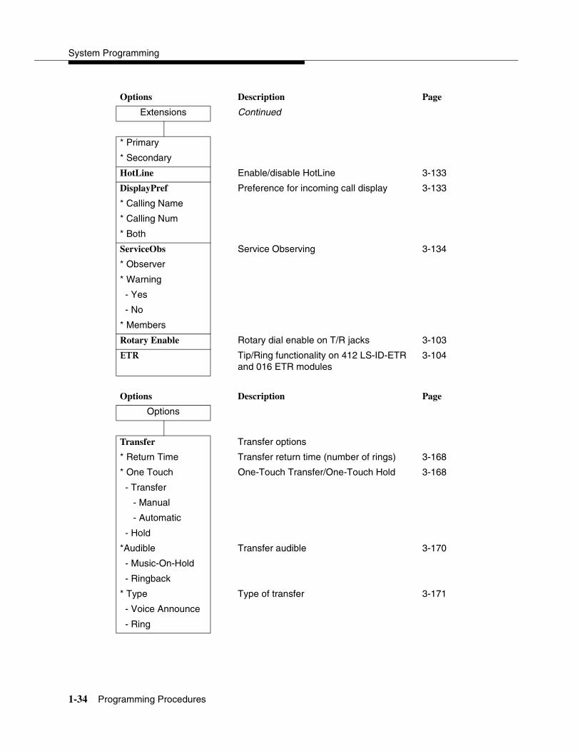
System Programming
1-34 Programming Procedures
Options Description Page
Extensions Continued
* Primary
* Secondary
HotLine Enable/disable HotLine 3-133
DisplayPref Preference for incoming call display 3-133
* Calling Name
* Calling Num
* Both
ServiceObs Service Observing 3-134
* Observer
* Warning
- Yes
- No
* Members
Rotary Enable Rotary dial enable on T/R jacks 3-103
ETR Tip/Ring functionality on 412 LS-ID-ETR and 016 ETR modules
3-104
Options Description Page
Options
Transfer Transfer options
* Return Time Transfer return time (number of rings) 3-168
* One Touch One-Touch Transfer/One-Touch Hold 3-168
- Transfer
- Manual
- Automatic
- Hold
*Audible Transfer audible 3-170
- Music-On-Hold
- Ringback
* Type Type of transfer 3-171
- Voice Announce
- Ring
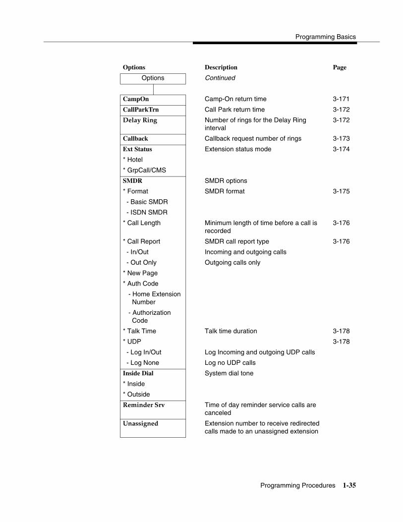
Programming Basics
Programming Procedures 1-35
Options Description Page
Options Continued
CampOn Camp-On return time 3-171
CallParkTrn Call Park return time 3-172
Delay Ring Number of rings for the Delay Ring interval
3-172
Callback Callback request number of rings 3-173
Ext Status Extension status mode 3-174
* Hotel
* GrpCall/CMS
SMDR SMDR options
* Format SMDR format 3-175
- Basic SMDR
- ISDN SMDR
* Call Length Minimum length of time before a call is recorded
3-176
* Call Report SMDR call report type 3-176
- In/Out Incoming and outgoing calls
- Out Only Outgoing calls only
* New Page
* Auth Code
- Home Extension Number
- Authorization Code
* Talk Time Talk time duration 3-178
* UDP 3-178
- Log In/Out Log Incoming and outgoing UDP calls
- Log None Log no UDP calls
Inside Dial System dial tone
* Inside
* Outside
Reminder Srv Time of day reminder service calls are canceled
Unassigned Extension number to receive redirected calls made to an unassigned extension
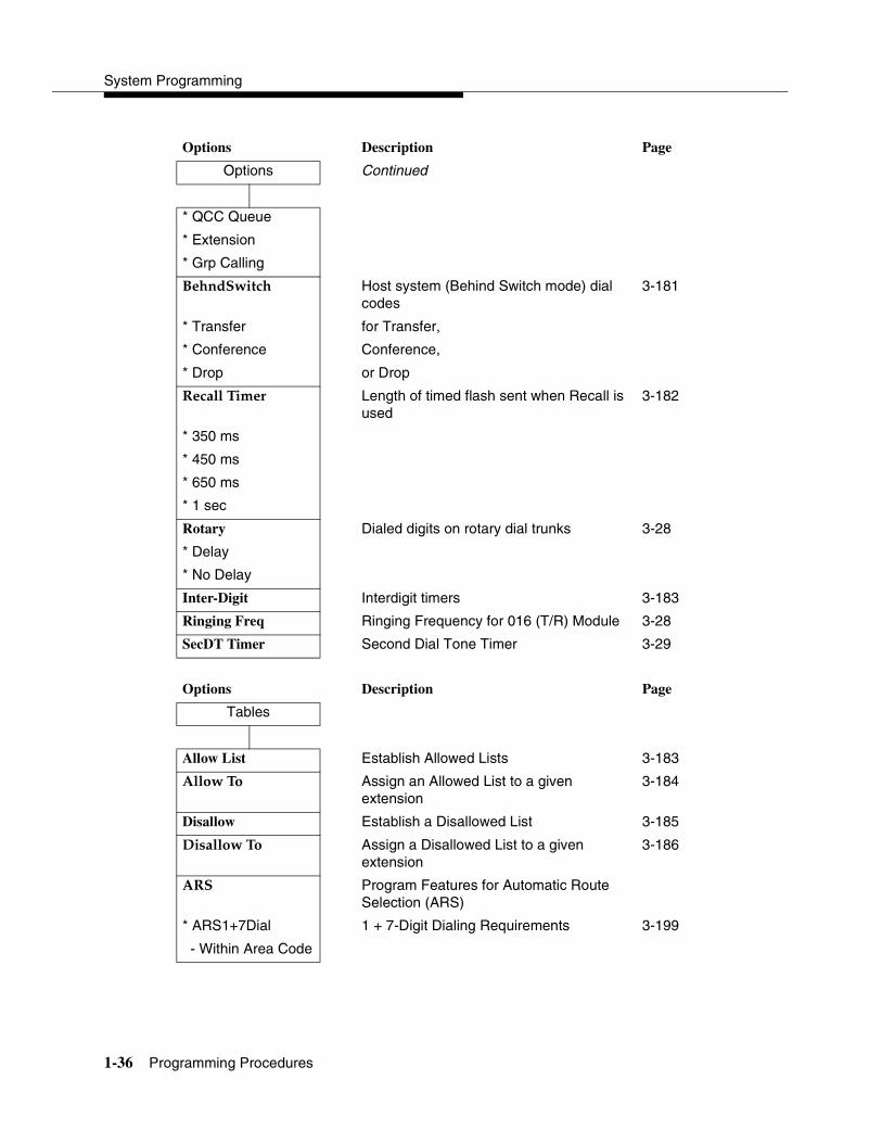
System Programming
1-36 Programming Procedures
Options Description Page
Options Continued
* QCC Queue
* Extension
* Grp Calling
BehndSwitch Host system (Behind Switch mode) dial codes
3-181
* Transfer for Transfer,
* Conference Conference,
* Drop or Drop
Recall Timer Length of timed flash sent when Recall is used
3-182
* 350 ms
* 450 ms
* 650 ms
* 1 sec
Rotary Dialed digits on rotary dial trunks 3-28
* Delay
* No Delay
Inter-Digit Interdigit timers 3-183
Ringing Freq Ringing Frequency for 016 (T/R) Module 3-28
SecDT Timer Second Dial Tone Timer 3-29
Options Description Page
Tables
Allow List Establish Allowed Lists 3-183
Allow To Assign an Allowed List to a given extension
3-184
Disallow Establish a Disallowed List 3-185
Disallow To Assign a Disallowed List to a given extension
3-186
ARS Program Features for Automatic Route Selection (ARS)
* ARS1+7Dial 1 + 7-Digit Dialing Requirements 3-199
- Within Area Code

Programming Basics
Programming Procedures 1-37
Options Description Page
Tables Continued
- Not Within Area Code
* ARS Input Create/Change ARS Tables 3-199
- 6-Digit
- Area Code
- Exchange
- 1+7
* Sub A Pools Subpattern A pool routing 3-201
* Sub A FRL Subpattern A Facility Restriction Level (FRL)
3-203
* SubA Absorb Subpattern A digit absorption 3-204
* Sub A Digit Subpattern A other digits 3-205
* Sub B Start Subpattern B start time 3-200
* Sub B Stop Subpattern B stop time 3-200
* Sub B Pool Subpattern B pool routing 3-201
* Sub B FRL Subpattern B Facility Restriction Level (FRL)
3-203
* SubB Absorb Subpattern B digit absorption 3-204
* Sub B Digit Subpattern B other digits 3-205
* SpeclNumber N11 Special Numbers Table 3-206
- ARS FRL
- ARS Digit
* Dial 0 Dial 0 Table 3-207
- ARS Pool
- ARS FRL
- ARS Digits
* Sub A Data Voice and/or data routing for Subpattern A 3-208
- Voice Only
- Data Only
- Voice/Data
* Sub B Data Voice and/or data routing for Subpattern B 3-208
- Voice Only
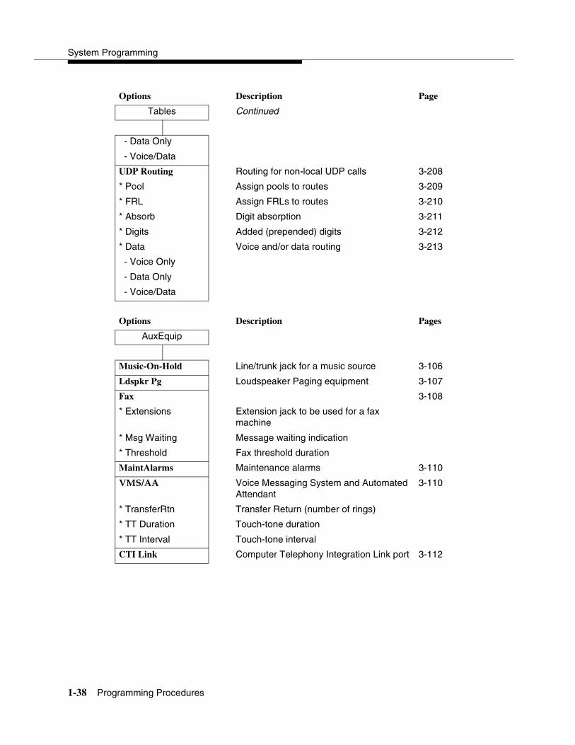
System Programming
1-38 Programming Procedures
Options Description Page
Tables Continued
- Data Only
- Voice/Data
UDP Routing Routing for non-local UDP calls 3-208
* Pool Assign pools to routes 3-209
* FRL Assign FRLs to routes 3-210
* Absorb Digit absorption 3-211
* Digits Added (prepended) digits 3-212
* Data Voice and/or data routing 3-213
- Voice Only
- Data Only
- Voice/Data
Options Description Pages
AuxEquip
Music-On-Hold Line/trunk jack for a music source 3-106
Ldspkr Pg Loudspeaker Paging equipment 3-107
Fax 3-108
* Extensions Extension jack to be used for a fax machine
* Msg Waiting Message waiting indication
* Threshold Fax threshold duration
MaintAlarms Maintenance alarms 3-110
VMS/AA Voice Messaging System and Automated Attendant
3-110
* TransferRtn Transfer Return (number of rings)
* TT Duration Touch-tone duration
* TT Interval Touch-tone interval
CTI Link Computer Telephony Integration Link port 3-112

Programming Basics
Programming Procedures 1-39
Options Description Page
NightSrvce
GroupAssign Night Service group assignment 3-214
* Extensions
* Calling Grp
* Lines
* CoverContrl
OutRestrict Password for use with out of hours calls 3-216
Emergency Emergency numbers free from password requirement
ExcludeList Extensions exempt from Night Service restrictions
Start Time of day Night Service is activated 3-217
Stop Time of day Night Service is deactivated 3-217
Time Control Turn Night Service Time Control on or off 3-217
* On
* Off
Cover Control 3-218
Options Description Pages
Labeling
Directory
* System System directory and internal speed dial numbers
3-223
* Extension Extensions to identify inside callers 3-220
* Personal Personal Directory listings
LinesTrunks Label used to identify line or trunk 3-221
PostMessage Change posted messages 3-221
Grp Calling Calling groups 3-222

System Programming
1-40 Programming Procedures
Options Description Pages
Data Data Options
Voice/Data Analog multiline telephones with voice and data
3-228
2B Data Enable 2B Data at MLX port 3-230
Options Description Pages
Print Print Screen Reports 3-224
All Print all reports
SysSet-up System Information report
Dial Plan Dial Plan report
NonLocl UDP Non-Local Dial Plan report
Labels Label Information report
Trunk Info Trunk Information report
* TIE Tie Trunk Information report
* DID DID Trunk Information report
* Loop/Ground GS/LS Trunk Information report
* General General Trunk Information report
* S56 Data Switched 56 Data Report
T1 Info DS1 Information report
PRI Info PRI (Primary Rate Interface) Information report
RmoteAccess Remote Access (DISA) report
Oper Info Operator Information report
AllowList Allowed Lists report
AllowListTo Access To Allowed Lists report
DisallowLst Disallowed Lists report
DisallowTo Access To Disallowed Lists report
ARS Automatic Route Selection report
Ext Direct Extension Directory report
Sys Direct System Directory report
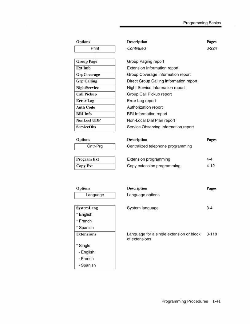
Programming Basics
Programming Procedures 1-41
Options Description Pages
Print Continued 3-224
Group Page Group Paging report
Ext Info Extension Information report
GrpCoverage Group Coverage Information report
Grp Calling Direct Group Calling Information report
NightService Night Service Information report
Call Pickup Group Call Pickup report
Error Log Error Log report
Auth Code Authorization report
BRI Info BRI Information report
NonLocl UDP Non-Local Dial Plan report
ServiceObs Service Observing Information report
Options Description Pages
Cntr-Prg Centralized telephone programming
Program Ext Extension programming 4-4
Copy Ext Copy extension programming 4-12
Options Description Pages
Language Language options
SystemLang System language 3-4
* English
* French
* Spanish
Extensions Language for a single extension or block of extensions
3-118
* Single
- English
- French
- Spanish
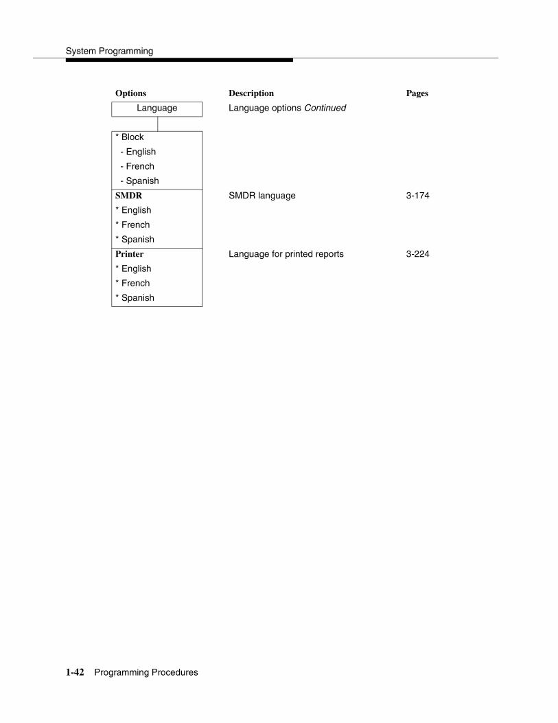
System Programming
1-42 Programming Procedures
Options Description Pages
Language Language options Continued
* Block
- English
- French
- Spanish
SMDR SMDR language 3-174
* English
* French
* Spanish
Printer Language for printed reports 3-224
* English
* French
* Spanish
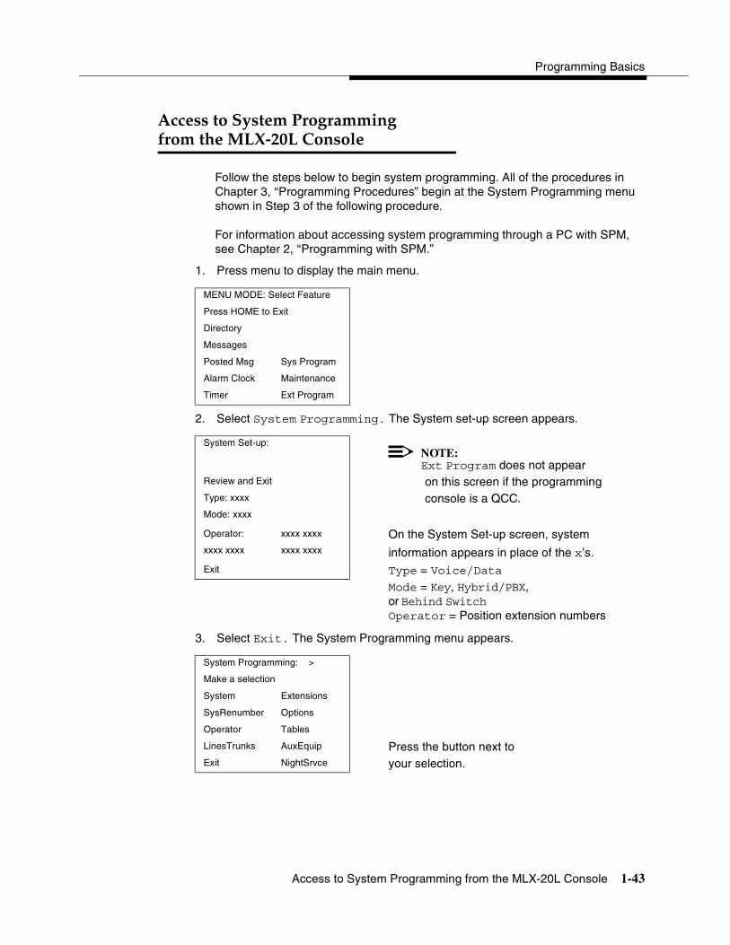
Programming Basics
Access to System Programming from the MLX-20L Console 1-43
Access to System Programmingfrom the MLX-20L Console 1
Follow the steps below to begin system programming. All of the procedures in Chapter 3, ‘‘Programming Procedures” begin at the System Programming menu shown in Step 3 of the following procedure.
For information about accessing system programming through a PC with SPM, see Chapter 2, ‘‘Programming with SPM.”
1. Press menu to display the main menu.
2. Select System Programming. The System set-up screen appears.
3. Select Exit. The System Programming menu appears.
MENU MODE: Select Feature
Press HOME to Exit
Directory
Messages
Posted Msg Sys Program
Alarm Clock Maintenance
Timer Ext Program
System Set-up:NOTE:Ext Program does not appear
Review and Exit on this screen if the programmingType: xxxx console is a QCC.Mode: xxxx
Operator: xxxx xxxx On the System Set-up screen, system xxxx xxxx xxxx xxxx information appears in place of the x’s.Exit Type = Voice/Data
Mode = Key, Hybrid/PBX, or Behind Switch Operator = Position extension numbers
System Programming: >
Make a selection
System Extensions
SysRenumber Options
Operator Tables
LinesTrunks AuxEquip Press the button next to Exit NightSrvce your selection.

System Programming
1-44 Access to System Programming from the MLX-20L Console
System Programming Menu 1
Figure 1-11 shows the two screens that make up the System Programming menu.
Figure 1-11. System Programming Menu Screens
Table 1-5 describes the options.
System Programming: > System Programming: >
Make a Selection Make a Selection
System Extensions Labeling Language
SysRenumber Options Data
Operator Tables Print
LinesTrunks AuxEquip Cntr-Prg
Exit NightSrvce Exit
Table 1-5. System Programming Menu Options
Option Description
System Set system operating conditions.
SysRenumber Select the system numbering plan and/or reassign extension numbers with 1- to 4-digit numbers that are more appropriate or convenient for your company.
Operator Assign or remove operator positions, and program operator features (such as Operator Hold Timer or QCC options).
LinesTrunks Program line/trunk options.
Extensions Program extension features (such as line assignments).
Options Program systemwide features (such as Transfer Return).
Tables Program features that require entering information in a table (such as Allowed Lists and Disallowed Lists).
AuxEquip Program auxiliary equipment connected to the system (such as loudspeaker paging and fax).
NightSrvce Program Night Service features.
Labeling Program the labels shown on display telephones (such as Posted Messages and entries in the System Directory).
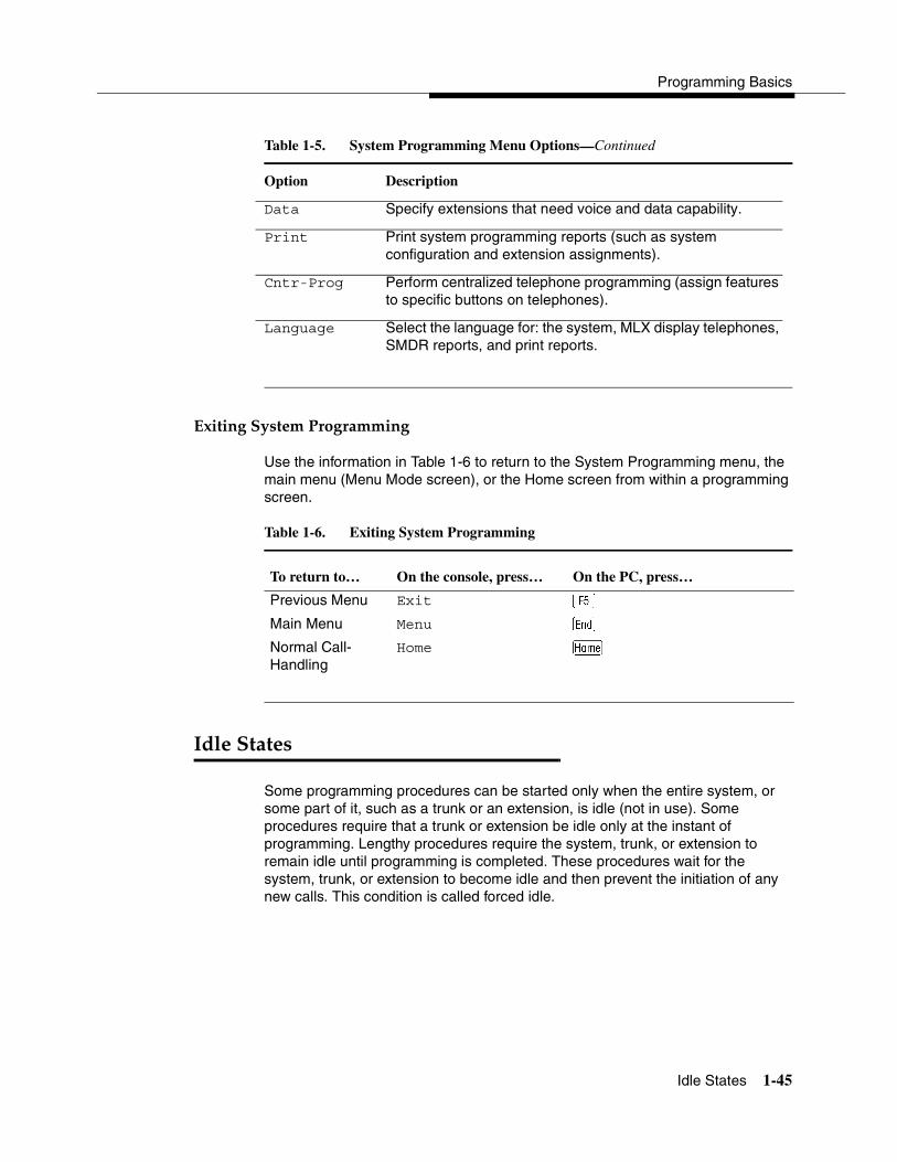
Programming Basics
Idle States 1-45
Exiting System Programming 1
Use the information in Table 1-6 to return to the System Programming menu, the main menu (Menu Mode screen), or the Home screen from within a programming screen.
Idle States 1
Some programming procedures can be started only when the entire system, or some part of it, such as a trunk or an extension, is idle (not in use). Some procedures require that a trunk or extension be idle only at the instant of programming. Lengthy procedures require the system, trunk, or extension to remain idle until programming is completed. These procedures wait for the system, trunk, or extension to become idle and then prevent the initiation of any new calls. This condition is called forced idle.
Data Specify extensions that need voice and data capability.
Print Print system programming reports (such as system configuration and extension assignments).
Cntr-Prog Perform centralized telephone programming (assign features to specific buttons on telephones).
Language Select the language for: the system, MLX display telephones, SMDR reports, and print reports.
Table 1-6. Exiting System Programming
To return to… On the console, press… On the PC, press…
Previous Menu Exit �
Main Menu Menu
Normal Call-Handling
Home �
Table 1-5. System Programming Menu Options—Continued
Option Description

System Programming
1-46 Idle States
NOTE:If a procedure requires an idle condition, do the programming outside of normal business hours.
If a procedure requires that the system be idle and the system is busy when you begin, you see the screen shown in Figure 1-12.
Figure 1-12. System Busy Screen
The screen changes to the appropriate programming screen when the system is no longer busy.
System Forced Idle 1
When the entire system is forced idle, no calls can be made or received. The following procedures can be performed only when the entire system (every line and every extension) is idle:
� Select system mode
� Identify system operator positions
� Renumber system
� Renumber boards
� Identify extensions with voice signal pairs for the Voice Announce to Busy feature
� Identify extensions that need voice and data features
� Restore system programming information
� Identify the Music-On-Hold jack
System Busy Pls Wait
Dial Code:nnnn S/P:ss/pp nnnn = a previously entered extensionss/pp = the slot and port number of thebusy extension
Exit Enter

Programming Basics
Idle States 1-47
When the system is forced idle, the following occurs: Multiline telephone users hear a signal, indicating that the telephone cannot be used; display telephone users see the message Wait: System Busy; single-line telephone users do not hear a dial tone.
Line or Trunk Idle 1
Because these procedures require the line or trunk to be idle only at the instant of programming, the line or trunk is not forced idle (as described in the previous paragraph). The following procedures can be performed only when the line or trunk being programmed is idle:
� Identify loudspeaker paging extension jack
� Assign trunks to pools
� Specify incoming or outgoing DID or tie-trunk type
� Specify tie-trunk direction
� Specify tie-trunk E&M signal
Extension Forced Idle 1
When an extension is forced idle, no calls can be made or received on that telephone or data equipment. The following procedures can be performed only when the extension being programmed is idle:
� Assign calling restrictions
� Assign pool dial-out restrictions
� Copy extension assignments
� Assign lines, trunks, or pools to extensions
� Assign labels to a personal directory
� Use centralized telephone programming
When the telephone is forced idle, the following occurs: Multiline telephone users hear a signal, indicating that the telephone cannot be used; display telephone users see the message Wait: System Busy; single-line telephone users do not hear a dial tone.
System Programming
1-48 Idle States
100D Module Idle 1
The following procedures can be performed only when the 100D module is idle:
� Specify board type
� Specify frame format
� Specify board signaling format
� Specify board suppression format
� Specify board facility compensation
Forced Idle Reminder Tones 1
The forced idle reminder tone is a high-low “doorphone” tone—400 ms of 667-Hz tone followed by 400 ms of 571-Hz tone. The tone is provided under the following circumstances:
� At the extension, to remind the user that the system or the extension is in the forced idle state.
� At the programming console or at a PC running SPM, to remind the system manager that the system (or at least one extension) is in the forced idle state because of administrative activity.
In Release 1.1 or later of the communications system, forced idle reminder tones occur every 20 seconds. You can adjust the volume of these tones with the volume control.
Contents
2-i
2Programming with SPM
Overview 2-1
System Requirements 2-2
Installing the SPM Software 2-4
� DOS Installation 2-4
Considerations 2-4
� DOS Installation with Windows 95 2-6
Considerations 2-6
Installation 2-7
Configuring a PIF file for DOS SPM 2-9
Hiding the spm.exe and spm.bat Files 2-10
� Initializing the SPM Software 2-10
Connecting the PC 2-13
� Direct Local Connection 2-13
� Local Modem Connection 2-15
� Remote Modem Connection 2-15
Accessing SPM 2-16
� Direct Local Connection 2-16
� Local or Remote Modem Connection 2-18
Considerations 2-18
Using SPM 2-20
� SPM Screens 2-21
� SPM Main Menu Options 2-25
� SPM Help 2-26

2-ii
Contents
System Programming
� Backup 2-26
Determining the Release Number of a Backup File 2-27
� Boards 2-30
� Browse 2-34
� Convert 2-35
� Language 2-41
PC Language 2-41
Console Window Language 2-41
� Maintenance 2-42
� Pass-Thru 2-43
� Password 2-46
� Print Options 2-47
SMDR Port Output 2-48
PC Port Output 2-48
� Restore 2-48
Considerations 2-49
System Programming 2-51
� Basic Programming Information 2-52
� Idle States 2-52
System Forced Idle 2-53
Line or Trunk Idle 2-53
Extension Forced Idle 2-54
Forced Idle Reminder Tone 2-54
� Accessing System Programming 2-55
� Printing Reports 2-55
Print Hard Copy 2-56
Print to Hard Disk 2-56
Print to Floppy Disk 2-57
Upgrading the System 2-57
� Before You Begin 2-58
� Upgrade Procedure 2-59
Surrogate Mode Programming 2-73

Overview 2-1
2sProgramming with SPM 2
Overview 2
The System Programming and Maintenance (SPM) software package offers an alternate method of programming the MERLIN LEGEND Communications System using a PC. This method frees the system programming console for other uses and also provides the additional functions listed below:
� Backing up system programming information.
� Restoring system programming information from a backup.
� Converting system programming information from one release to another (part of the upgrade procedure).
� Printing, viewing, and storing reports.
� Programming the communications system remotely.
� Programming in surrogate mode.
SPM software is available in DOS (which can run as a DOS application or can be installed to run with Windows 95) or UNIX (as part of Intuity Integrated Solution II1, or Integrated Solution III1).
NOTE:The System Programming and Maintenance (SPM) software is available in a Windows format called WinSPM. For Release 6.0 and later systems, WinSPM provides a graphical user interface (GUI) for
1 Can no longer be ordered.
System Programming
2-2 System Requirements
those tasks most commonly performed by the system manager (for example, add or delete members of groups, perform system inventories, create reports, administer multiple systems, make station labels shown on display telephones, and more). Pictorial representations of system components, such as modules and their vintages, and the creation of MLX telephone button labels are available with WinSPM. WinSPM also provides an SPM DOS Emulator mode that allows basic SPM programming of all releases of the MERLIN LEGEND System. Also supported in Release 6.0 and later systems is SPM programming for options not included in the GUI. For Release 6.0 and later systems, WinSPM is supported in Windows 95, Windows NT, and Windows 98, and is available on CD-ROM and floppy disks.
DOS SPM and WinSPM software can be used directly from the floppy disks or CD-ROM on your PC. If your PC has a hard disk, however, you should install DOS SPM or WinSPM from either the floppy disks or CD-ROM onto the hard disk.
This guide describes the use of SPM on a PC with a DOS operating system or use of WinSPM in the SPM DOS Emulator mode. If you are using WinSPM, refer to the documentation and online help provided with the WinSPM application for additional information. If your system includes the Intuity or IS II/III applications, you have the UNIX System version of SPM.
For information about accessing SPM from the IS II/III application, refer to the following books:
� Integrated Solution III System Manager’s Guide, order no. 555-601-010
� Integrated Solution III Installation and Maintenance Guide, order no. 555-601-011
� Integrated Solution II System Manager’s Guide, order no. 555-600-726
� Integrated Solution II Installation and Maintenance Guide, order no. 555-600-720
System Requirements 2
To use SPM for system programming, you need the SPM diskette and an approved PC with version 3.3 (or later) of MS-DOS. At a minimum, your PC should support and include the following items:
� At least 640 kbytes of RAM
� A floppy disk drive to accommodate the SPM disk (3.5-inch or 5.25-inch)
� A monochrome or color monitor

Programming with SPM
System Requirements 2-3
� A serial port that can use either a DB-9 or DB-25 connector
NOTE:For a DB-9 connector, use a 9-pin to 25-pin adapter to attach the 25-pin connector of the RS-232 interface cable.
� An RS-232 interface cable of appropriate length for your site connection
Depending on how you connect the PC to the control unit, you also need the following items:
� Direct local connection, if the PC is within 50 feet of the control unit:
— Either a 355AF modular adapter (if there is a male connector on the interface cable) or a 355A modular adapter (if there is a female connector on the interface cable)
— A four-pair modular cord (D8W)
� Direct local connection, if the PC is more than 50 feet from the control unit:
— 355AF adapter
— EIA crossover cable
— Two Z3A2 Asynchronous Data Units (ADUs)
— ADU crossover cable
— 400B2 power adapter
— 2012D transformer
— BR1A-4P adapter and either a 102 connecting block or 103 connecting block
— 248B adapter
— Eight-position wall jacks
— Four-pair plug-ended cable
— D8W cords
— D6AP power cord
— EIA-232-D cables
� Modem (local or remote) connection:
— Modem that supports 1200- or 2400-bps connections
— Modem cable
In addition, a parallel printer is useful for reports. The PC needs a parallel port for the connection.

System Programming
2-4 Installing the SPM Software
NOTE:SPM uses Interrupt 4 and I/O address 3F8 for COM1. It uses Interrupt 3 and I/O address 2F8 for COM2.
Installing the SPM Software 2
Before you install or run SPM, it is recommended that you use diskcopy on a DOS PC (see your operating system guide) to make a backup copy of the SPM disk. Store the original in a safe place. Use the backup copy to run the installation program.
For installing DOS SPM on a PC, follow the appropriate instructions in the next section. For installing DOS SPM on a Windows 95 PC, follow the instructions provided in ‘‘DOS Installation with Windows 95’’ on page 2-6.
NOTE:If your PC does not have a hard disk, you do not need to run the installation program. Go to ‘‘Initializing the SPM Software’’ on page 2-10.
DOS Installation 2
Use the following procedure to install SPM on the hard drive of a DOS PC.
NOTE:If you are updating SPM, you do not need to remove the current SPM files. The new files will overwrite your current SPM files.
Considerations 2
Review the following items before you begin the installation procedure.
The installation program automatically performs the following:
� Checks available space on the hard disk. If space is insufficient, the installation is terminated and an error message is generated.
� Checks the autoexec.bat and config.sys files. If either file is write-protected, the installation is terminated and an error message is generated. SPM must make changes to these files.
� Saves a copy of autoexec.bat as autoexec.old.
� Saves a copy of config.sys as config.old.
� If autoexec.bat has not already been configured for SPM:
— Adds c:\spm to the path statement.
Programming with SPM
Installing the SPM Software 2-5
— Adds the line SET AMS_PATH=C:
— Adds the background print command:PRINT /D:PRN /B:4096 /U:3 /M:200 /S:1 >NUL
� Adds the following line to config.sys, if it is not already present:DEVICE=C:\ANSI.SYS
� Copies the ansi.sys file from the floppy disk to c:\.
� Creates the directory c:\spm.
� Copies the following files from the floppy disk into the c:\spm directory:
— spm.exe.
— ams_hlp.eng (English language Help file).
— ams_hlp.fre (French language Help file).
— sams_hlp.spa (Spanish language Help file).
� Creates the following directories if they do not already exist:
— c:\spm\backup.
— c:\spm\reports.
— c:\spm\tmp.
� Does one of the following:
— Creates the SPM configuration file c:\spm\ams.cfg, if it does not already exist. In this case, the ams.cfg file consists of only one line, in which the language attribute is specified: LANG 1 if you specified English or did not specify a language with the install command.
— Modifies the ams.cfg file, if it already exists, by adding or changing the LANG value.
Follow the steps below to install SPM on the PC’s hard disk.
1. Switch to Drive A, if it is not already the current drive.
A:> appears on the screen.
2. Insert the backup copy of the SPM disk into Drive A.
3. Type one of the commands shown below and press �:
� install
� install french
� install spanish

System Programming
2-6 Installing the SPM Software
Because English is the default language, install and install english have the same result. If you do use the language argument (english, french, or spanish), you must type it in lowercase letters as shown. The command install may be uppercase or lowercase.
4. Wait for the message shown below to appear.
SPM HARD DISK INSTALLATION PROGRAMStrike a key when ready
5. Press any key to begin the installation.
When the installation is finished, the following message appears:
SPM HARD DISK INSTALLATION IS NOW COMPLETEYOU MUST REBOOT YOUR SYSTEM BEFORE USING SPM
6. Remove the SPM disk from Drive A and reboot your system.
The installation procedure is complete. Go to ‘‘Initializing the SPM Software’’ on page 2-10.
DOS Installation with Windows 95 2
Using DOS SPM with Windows 95 improves the interaction of SPM with the operating system compared to a Windows 3.x installation. For example, the interaction with the print driver is improved. If an online printer is not available when you try to print while using SPM, you see a message box explaining the problem. You can correct the problem by bringing the printer online and continuing, or you can cancel the print operation. SPM operation is not affected by the error message or the action you take to correct the problem.
NOTE:This procedure is used to install the DOS version of SPM to run with Windows 95. Do not use this procedure if you have the WinSPM application. For WinSPM, refer to the documentation that was provided with the application.
Use the following procedure to install SPM. You do not need to remove the current SPM files. The new files automatically overwrite your current SPM files.
Considerations 2
Review the following items before you begin the installation procedure.
The installation program automatically performs the following functions.

Programming with SPM
Installing the SPM Software 2-7
� If you typed install (the command for DOS installation) instead of instal95, checks that your PC has Windows 95 installed. If Windows 95 is detected, you see an error message that tells you to run the Instal95 program.
� Creates the directory c:\spm, if it does not already exist.
� Checks if the print.exe file is present in any directory listed in the PATH environment variable.
� Runs the DOS SETVER command to set the version table for print.exe to 6.22. This is required to enable print.exe to run on Windows 95.
� Creates an spm.bat file in the directory c:\spm. The spm.bat file contains the ams_path and print statements required to run SPM.
� Unzips and copies the remaining files into the directory c:\spm.
� Instructs you to refer to this document for details on using the PIF Editor to configure an SPM PIF file to work with the spm.exe file.
Installation 2
With Windows 95 running on your PC, follow these steps to install SPM on the PC’s hard disk:
1. Insert the SPM installation disk in any floppy disk drive (usually the A drive).
2. Choose either of the following two methods to install SPM:
Method 1 – Install DOS SPM with French, Spanish, or English Language: 2
a. Open a DOS window from Windows Explorer.
b. At the DOS prompt, switch to the drive with the SPM installation disk (usually the A drive).
c. At the DOS prompt, type one of the commands shown below and press �.
� instal95 or instal95 english
� instal95 french
� instal95 spanish
NOTE:Because English is the factory-set language, instal95 and instal95english have the same result. If you do use the language argument (english, french, or spanish), you must type it in lowercase letters as shown. The command instal95 may be in uppercase or lowercase letters.
System Programming
2-8 Installing the SPM Software
Method 2 – Install DOS SPM with French, Spanish, or English Language: 2
a. From Windows Explorer, select the floppy drive that contains the backup copy of the SPM disk.
b. Select and run Instal95 (either by double-clicking the file name, or single-clicking the file name and, from the File menu, selectingOpen).
3. After you start the DOS SPM installation using either method, the following message appears:
SPM WINDOWS 95 HARD DISK INSTALLATION PROGRAMPress any key to continue
4. Press any key to begin the installation.
5. If your PC does not have a copy of print.exe in any directory listed in your system’s PATH environment, the following message appears:
Copying print.exe to directory c:\spmfile(s) copied.
WARNING - The application you are adding to the Windows version table may not have been verified by Microsoft in this version of Windows. Please contact your software vendor for information on whether this application will operate properly under this version of Windows. If you execute this application by instructing Windows to report a different MS-DOS version number, you may lose or corrupt data, or cause system instabilities. In that circumstance, Microsoft is not responsible for any loss or damage.
Version table successfully updated.The version change will take effect the next time you restart your system.
*******************************************************
SPM Note: The warning message seen above was produced by the SETVER command. This command was used in the SPM install program to set the proper version of PRINT.EXE file in the DOS version table. Please note that in Windows 95, running SETVER always produces the warning message seen above, even when the command is run properly.
*******************************************************
Press any key to continue. . .
Programming with SPM
Installing the SPM Software 2-9
6. Press any key to continue installation. When SPM installation is complete the following message appears:
Installation of SPM for DOS on your Windows 95 hard drive is now complete. For easy access to SPM from Windows 95, configure an SPM.PIF file. See the SPM Manual for details. Press any key to continue . . .
7. Press any key.
If you installed DOS SPM using Method 1 in Step 2, type exit at the DOS prompt and press � to close the DOS window. If the window does not close, then the Close on Exit option for the DOS window is not set. Click the
in the upper right corner of the window to close it.
If you installed DOS SPM using Method 2 in Step 2, the DOS window closes automatically.
8. If the print.exe file was copied to your PC in Step 4, you must reboot your PC.
9. Configure a PIF file for SPM using the instructions that follow.
Configuring a PIF file for DOS SPM 2
Refer to the Windows 95 Help topic, “PIF Editor,” for details about using the PIF editor to implement an SPM PIF file to work with the spm.exe file.
To configure a PIF file for DOS SPM, use the following steps:
1. In Windows Explorer, select the SPM application file, and then, from the File menu, select Properties. A tabbed window displays.
2. In Program Tab, enter the following line in the Working Directory entry:
C:\SPM
3. In Program Tab, enter the following line in the Batch File entry:
C:\SPM\SPM.BAT
4. In Program Tab, make sure the Close on Exit check box is selected.
You can now double-click either the SPM application icon or the SPM Shortcut to MS-DOS icon to run SPM. When you quit SPM (by pressing the Home key), the window closes automatically.
X

System Programming
2-10 Installing the SPM Software
Hiding the spm.exe and spm.bat Files 2
To hide the spm.exe and spm.bat files, use the following steps:
1. In Windows Explorer, select each file.
2. From the File menu, select Properties.
The Properties dialog box displays.
3. In the Attributes section of the General Tab, click the Hidden check box.
Initializing the SPM Software 2
To run correctly, the DOS version of SPM requires certain information (transmission speed, type of monitor, and so on). You must supply this information only once—the first time you run SPM.
The information you provide during the initialization process is written to the SPM configuration file (ams.cfg). If you need to change this information at some later time, you can do so in either of the following ways:
� Use any of the options in Table 2-1 to change the information in ams.cfg.
� Edit the ams.cfg file. (If you are unsure about editing the file, you can remove it. You are prompted to reinitialize the next time you invoke SPM. The file is created at that time.)
NOTE:The DEBUG attribute is also specified in ams.cfg as DEBUG=0 (off—the factory setting), or DEBUG=1 (on). This attribute is used to enable the Escape-to-Shell feature of SPM, activated by pressing � + �. To turn DEBUG on, you must edit the ams.cfg file; it is not part of the initialization process. The DEBUG attribute is for use by qualified service personnel only.
Table 2-1. SPM Configuration File (ams.cfg) Options
Option Use
spm -com1 Specifies COM1 as the serial communications port used by SPM
spm -com2 Specifies COM2 as the serial communications port used by SPM
spm -s1200 Specifies modem speed of 1,200 bps
spm -s2400 Specifies modem speed of 2,400 bps

Programming with SPM
Installing the SPM Software 2-11
To perform the SPM initialization, follow the steps below:
1. Type spm and press � to display the SPM Welcome screen shown in Step 2.
� If you have installed SPM on your PC’s hard disk, make your entry at the C:> prompt.
� If you are using the floppy drive, make your entry at the A:> prompt.
2. Press any key.
The screens shown in Steps 3 through 7 appear only if the system has not been initialized. Otherwise, the screen shown in Step 8 appears.
3. Select the serial communications port used for SPM and press �.
spm -color Specifies color monitor
spm -mono Specifies monochrome monitor
spm -1 english Specifies English as the PC language
spm -1 french Specifies French as the PC language
spm -1 spanish Specifies Spanish as the PC language
Welcome to SPM X.XX = current version of SPMThe MERLIN LEGEND
System Programming
& Maintenance Utility
Please press any key
to continue
Version X.XX
COMM PORT: Type 1 for serial port 1 (COM1).1. Comm 1 Type 2 for serial port 2 (COM2).2. Comm 2
Enter selection #
Table 2-1. SPM Configuration File (ams.cfg) Options—Continued
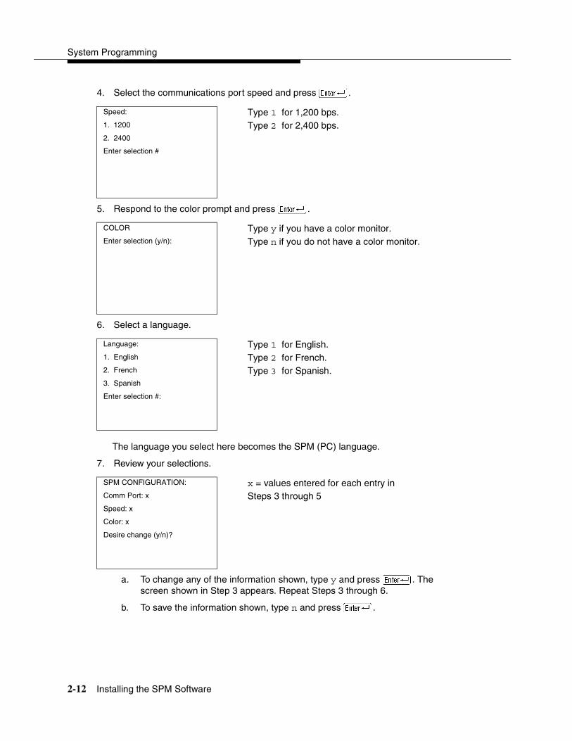
System Programming
2-12 Installing the SPM Software
4. Select the communications port speed and press �.
5. Respond to the color prompt and press �.
6. Select a language.
The language you select here becomes the SPM (PC) language.
7. Review your selections.
a. To change any of the information shown, type y and press �. The screen shown in Step 3 appears. Repeat Steps 3 through 6.
b. To save the information shown, type n and press �.
Speed: Type 1 for 1,200 bps.1. 1200 Type 2 for 2,400 bps.2. 2400
Enter selection #
COLOR Type y if you have a color monitor.Enter selection (y/n): Type n if you do not have a color monitor.
Language: Type 1 for English.1. English Type 2 for French.2. French Type 3 for Spanish.3. Spanish
Enter selection #:
SPM CONFIGURATION: x = values entered for each entry in Comm Port: x Steps 3 through 5Speed: x
Color: x
Desire change (y/n)?

Programming with SPM
Connecting the PC 2-13
— If the PC is connected to the processor, the SPM Main Menu appears as shown in Step 8.
— If the PC is not connected, go to ‘‘Connecting the PC’’ on page 2-13.
8. Press the function key that corresponds to the desired option.
NOTE:The function keys shown on either side of the display are included here for quick reference. See ‘‘SPM Screens’’ on page 2-21 for details on using the PC keys in SPM.
Connecting the PC 2
There are three ways to connect the PC to the control unit. Choose the method below that is most useful for your installation.
� Direct local connection
� Local modem connection
� Remote modem connection
Direct Local Connection 2
For a direct local connection, you must connect the PC to the system programming jack. This is the lower modular RS-232 jack on the processor module, as shown in Figure 2-1. (The upper jack is reserved for the SMDR printer.)
To connect a PC more than fifty feet from the control unit, see Figure 2-2.
For direct local connections, the system supports speeds of 1,200 and 2,400 bps.
NOTE:You must use a direct local connection to program in surrogate mode.
SPM Main Menu
Menu: Select Function
� Sys Program Maintenance �
� Backup Restore �
� Boards Pass-Thru
Print Opts Password �
� Monitor Language �

System Programming
2-14 Connecting the PC
Figure 2-1. Direct Local Connection
Figure 2-2. Direct Local Connection, PC More Than 50 Feet Away
CAUTION
POWER
ON
OFF
AG INPUTAG INPUT
FRFR
GNDGND
Turn offpower beforeinserting orremovingmodules
408
GS
/LS
44G
S o
r LS
Out
side
Lin
es/
8 A
nalo
g Te
leph
ones
(ATL
)
408 008
MLX
8 M
LX (D
igita
l) Te
leph
ones
012
PR
OC
ES
SO
R
355AFAdapter
SystemProgrammingJack
SerialCommunicationsPort
D8WRS-232
CAUTION
POWER
ON
OFF
AG INPUT
FRGND
Turn offpower beforeinserting orremovingmodules
408 G
S/L
S44G
S o
r LS
Outs
ide L
ines/
8 A
nalo
g T
ele
phones (
AT
L)
408
008 M
LX
8 M
LX
(D
igital) T
ele
pho
nes
012
PR
OC
ES
SO
R
AC Outlet
D8W
D8W
D6AP
Z3A2 ADU
EIA-232-D
DIW
102 or 103Connecting Block
2012D-50MTransformer
EIA-232-D
BR1A-4P Adapteror
102 Connecting Blockor
103 Connecting Block
ADU Crossover Cable Control Unit
Processor Module
EIACrossover
Cable
Z3A2 ADU
SMDRJackADMINJack
355AFAdapter
8DW
or Direct Connection
WallJack
WallJack
4 Pair PlugEnded Cable
BuildingWiring
or
Cable Joints
D8W
400B2Power
Adapter

Programming with SPM
Connecting the PC 2-15
Local Modem Connection 2
For a local modem connection, you must use a modem (either connected to, or built into, the PC) to access the internal modem in the control unit. Connect the modem to a T/R jack on an 012 (T/R) or 016 (T/R) module, or to a jack that has been programmed for T/R on a 412 LS-ID-ETR or 016 ETR module in the control unit, as shown in Figure 2-3.
The internal modem operates at speeds of 1,200 and 2,400 bps.
Figure 2-3. Local Modem Connection
Remote Modem Connection 2
For a remote modem connection, you must use a modem (either connected to, or built into, the PC) to access the internal modem in the control unit. You must also use a dial-up connection, as shown in Figure 2-4. See ‘‘Accessing SPM’’ on page 2-16 for details on accessing SPM with a remote modem connection.
The internal modem operates at speeds of 1,200 and 2,400 bps.
CAUTION
POWER
ON
OFF
AG INPUT
FRGND
Turn offpower beforeinserting orremovingmodules
408
GS
/LS
44G
S o
r LS
Out
side
Lin
es/
8 A
nalo
g Te
leph
ones
(ATL
)
408 008
MLX
8 M
LX (D
igita
l) Te
leph
ones
012
PR
OC
ES
SO
R
RS-232
012 (T/R)Port
SerialCommunicationsPort
MODEM

System Programming
2-16 Accessing SPM
Figure 2-4. Remote Modem Connection
NOTE:Remote access (modem connection) has priority over local access (direct connection), unless a backup or restore procedure is in progress through a direct local connection. If a modem connection is attempted while any other type of onsite programming is in progress (either at the system or at a directly connected PC), the system sends a message to the onsite programmer. The message indicates that a modem connection is being established and the onsite programming session is terminated.
Accessing SPM 2
The procedure for accessing SPM depends on whether your PC is connected to the control unit with a modem (either local or remote) or without a modem (direct). This section covers both of these access procedures.
Direct Local Connection 2
To access SPM when your PC is connected directly to the control unit, follow the steps below:
1. Set up the appropriate physical connections between the PC and the control unit.
See ‘‘Connecting the PC’’ on page 2-13.
CAUTION
POWER
ON
OFF
AG INPUT
FRGND
Turn offpower beforeinserting orremovingmodules
408
GS
/LS
44G
S o
r LS
Out
side
Lin
es/
8 A
nalo
g Te
leph
ones
(ATL
)
408 008
MLX
8 M
LX (D
igita
l) Te
leph
ones
012
PR
OC
ES
SO
R
RS-232
SerialCommunicationsPort
Incoming trunk line
Public or private telephone network
MODEM
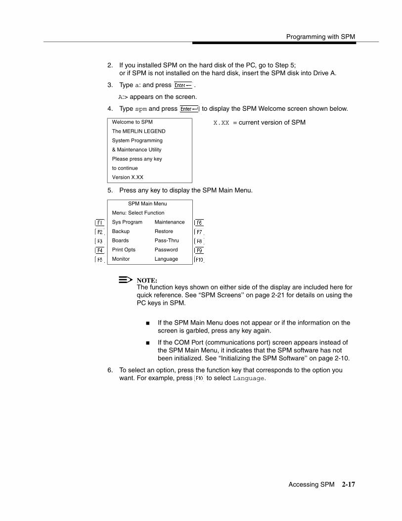
Programming with SPM
Accessing SPM 2-17
2. If you installed SPM on the hard disk of the PC, go to Step 5;or if SPM is not installed on the hard disk, insert the SPM disk into Drive A.
3. Type a: and press �.
A:> appears on the screen.
4. Type spm and press � to display the SPM Welcome screen shown below.
5. Press any key to display the SPM Main Menu.
NOTE:The function keys shown on either side of the display are included here for quick reference. See ‘‘SPM Screens’’ on page 2-21 for details on using the PC keys in SPM.
� If the SPM Main Menu does not appear or if the information on the screen is garbled, press any key again.
� If the COM Port (communications port) screen appears instead of the SPM Main Menu, it indicates that the SPM software has not been initialized. See ‘‘Initializing the SPM Software’’ on page 2-10.
6. To select an option, press the function key that corresponds to the option you want. For example, press � to select Language.
Welcome to SPM X.XX = current version of SPM The MERLIN LEGEND
System Programming
& Maintenance Utility
Please press any key
to continue
Version X.XX
SPM Main Menu
Menu: Select Function
� Sys Program Maintenance �
� Backup Restore �
� Boards Pass-Thru
Print Opts Password �
� Monitor Language �
System Programming
2-18 Accessing SPM
Local or Remote Modem Connection 2
The method you use to access SPM by modem depends on whether you are programming onsite (locally) or from a remote location.
� If you are onsite, the modem must be connected to a T/R jack on an 012 (T/R) or 016 (T/R) module, or to a jack that has been programmed for T/R on a 412 LS-ID-ETR or 016 ETR module on the control unit. To establish a connection to the control unit’s internal modem, dial *10.
� If you are at a remote location, do either of the following:
— Place a call to the system on a Remote Access line, enter the barrier code (if required), and dial the code for the internal modem (*10).
— Place a voice call to the system using the line to which the modem is connected and ask the operator to transfer you to the modem (press Transfer, dial *10, then hang up the telephone). When you hear the modem answer tone, switch to data mode.
Considerations 2
Review the following items before you begin the modem connection procedure.
Set the Programming Language 2
If you prefer to program in a language other than the current SPM language setting, see ‘‘Language’’ on page 2-41.
Modem Connections 2
You must make a data connection to a modem. The following modem dialing commands are for Hayes® and Hayes-compatible modems. These may not be the commands your modem uses; refer to the user guide that came with your modem for specific information.
� If the PC is in the same location as the control unit, type *10.
� If the PC is in a remote location and your system has the Remote Access feature activated, type the following and press �:
— Without barrier codes, type:
ATDT; the remote access telephone number; and W*10. For example: ATDT12015551234 W*10 �.
— With barrier codes, type:
ATDT; the remote access telephone number; and the barrier code preceded by a “W” and W*10. The barrier code in the example below is 555555.For example: ATDT12015551234 W555555 W*10 �.
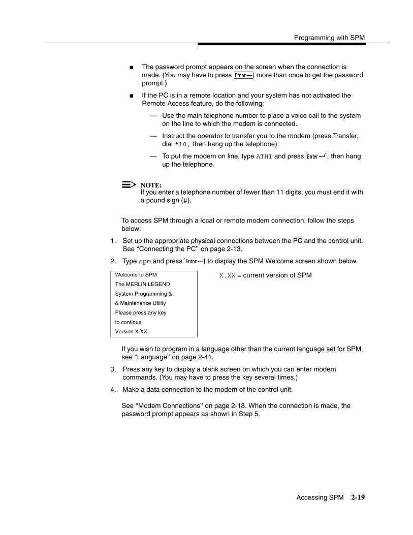
Programming with SPM
Accessing SPM 2-19
� The password prompt appears on the screen when the connection is made. (You may have to press �more than once to get the password prompt.)
� If the PC is in a remote location and your system has not activated the Remote Access feature, do the following:
— Use the main telephone number to place a voice call to the system on the line to which the modem is connected.
— Instruct the operator to transfer you to the modem (press Transfer, dial *10, then hang up the telephone).
— To put the modem on line, type ATH1 and press �, then hang up the telephone.
NOTE:If you enter a telephone number of fewer than 11 digits, you must end it with a pound sign (#).
To access SPM through a local or remote modem connection, follow the steps below:
1. Set up the appropriate physical connections between the PC and the control unit. See ‘‘Connecting the PC’’ on page 2-13.
2. Type spm and press � to display the SPM Welcome screen shown below.
If you wish to program in a language other than the current language set for SPM, see ‘‘Language’’ on page 2-41.
3. Press any key to display a blank screen on which you can enter modem commands. (You may have to press the key several times.)
4. Make a data connection to the modem of the control unit.
See ‘‘Modem Connections’’ on page 2-18. When the connection is made, the password prompt appears as shown in Step 5.
Welcome to SPM X.XX = current version of SPMThe MERLIN LEGEND
System Programming &
& Maintenance Utility
Please press any key
to continue
Version X.XX

System Programming
2-20 Using SPM
5. Type the SPM password to display the SPM Main Menu shown in Step 6.
The password does not display as you type it.
6. To select an option, press the function key that corresponds to the option you want. For example, press � to select Language.
NOTE:The function keys shown on either side of the display are included here for quick reference. See ‘‘SPM Screens’’ on page 2-21 for details on using the PC keys in SPM.
Using SPM 2
This section describes how to use the SPM screens, SPM Help, and the following SPM options:
� Backup
� Boards
� Browse
� Convert
� Language
� Maintenance
� Monitor
� Pass-Thru
Enter Password:
SPM Main Menu
Menu: Select Function
� Sys Program Maintenance � � Backup Restore � � Boards Pass-Thru Print Opts Password � � Monitor Language �
Programming with SPM
Using SPM 2-21
� Password
� Print Options
� Restore
� System Programming
NOTE:If you are using WinSPM, Backup, Restore, and Convert can be selected from the Main Menu. For Release 6.0 and later systems, the System Inventory option in the Quick Access mode provides a graphical representation of your system inventory, which includes all modules and versions. For all other options and for all MERLIN LEGEND System releases, all of the options listed above are available in the SPM DOS Emulator mode. For additional information on using WinSPM, refer to the documentation and online help provided with WinSPM.
Some of the procedures described in this section should be performed by qualified service personnel only.
SPM Screens 2
SPM screens simulate the system programming console. Each SPM screen includes a 7-line by 24-character console simulation window that corresponds to the display area of the MLX-20L telephone. To the right and left of this console simulation window are columns that list the keys corresponding to similarly located buttons on the MLX-20L telephone. If you are working with Version 2.0 or higher, the version number appears in the upper left corner of the screen (for example, V6). Figure 2-5 illustrates the SPM display screen.
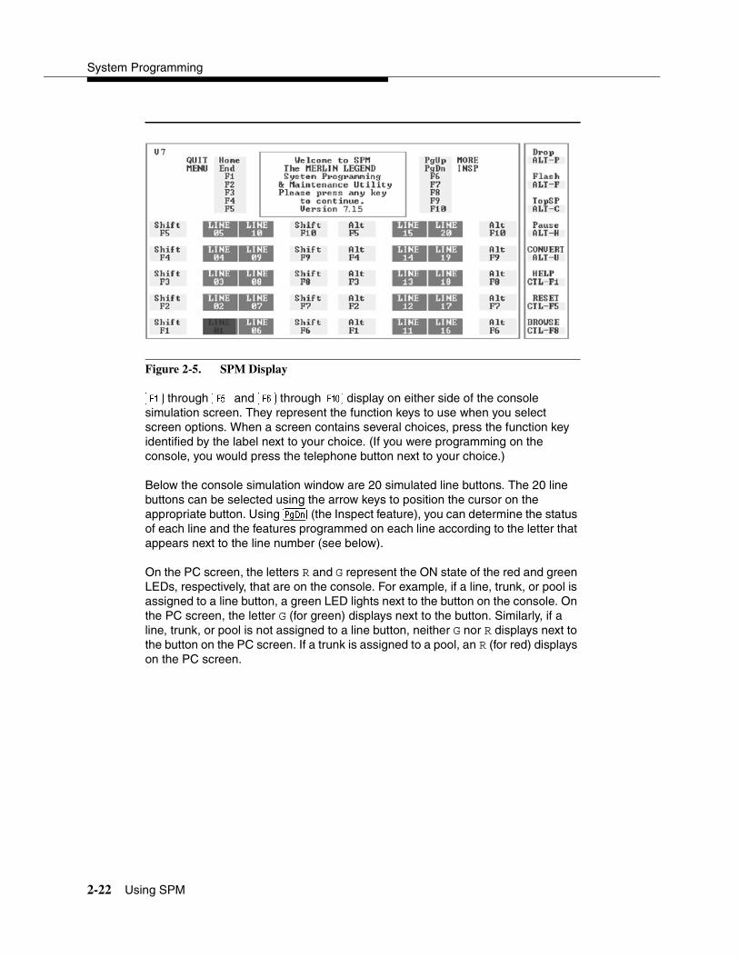
System Programming
2-22 Using SPM
Figure 2-5. SPM Display
� through � and � through � display on either side of the console simulation screen. They represent the function keys to use when you select screen options. When a screen contains several choices, press the function key identified by the label next to your choice. (If you were programming on the console, you would press the telephone button next to your choice.)
Below the console simulation window are 20 simulated line buttons. The 20 line buttons can be selected using the arrow keys to position the cursor on the appropriate button. Using � (the Inspect feature), you can determine the status of each line and the features programmed on each line according to the letter that appears next to the line number (see below).
On the PC screen, the letters R and G represent the ON state of the red and green LEDs, respectively, that are on the console. For example, if a line, trunk, or pool is assigned to a line button, a green LED lights next to the button on the console. On the PC screen, the letter G (for green) displays next to the button. Similarly, if a line, trunk, or pool is not assigned to a line button, neither G nor R displays next to the button on the PC screen. If a trunk is assigned to a pool, an R (for red) displays on the PC screen.

Programming with SPM
Using SPM 2-23
The labels in the column on the right side of the screen show key combinations that correspond to buttons on the MLX-20L telephone. Table 2-2 describes the function of PC keys in SPM.
Table 2-2. Function of PC Keys in SPM
PC Key Console SPM Function
� Home Quit. Exit from SPM and return to the DOS prompt when you finish with system programming. If you are using a modem, the call is disconnected.
� Menu Return to the SPM Main menu.
� More Display more menu items (when there is another screen and the > symbol appears next to the key).
� Inspct Display the current information that has been programmed for a feature or button.
��� Drop Enter a stop in a speed-dialing sequence. This combination also deletes an entry in a field on any screen, except the one in which you are entering a speed-dialing sequence.
��� Conf Flash. Enter a switchhook flash in a speed-dialing sequence.
��� n/a TopSP. Return to the top of the System Programming menu.
��� Hold Pause. Enter a pause in a speed-dialing sequence.
��� n/a Convert. Convert a backup file from its original release format to a different release format.
��� n/a Toggle modem speed between 1,200 and 2,400 bps.
��� n/a Help. Display a Help screen about SPM operations. To exit from Help, press �.
��� n/a Reset. Reset the communications port. For example, if the information on the screen is garbled, try exiting from and then re-entering the screen. If the screen remains garbled, use ��� to clear the screen and return to the SPM Welcome screen. Note that using��� drops the modem connection.

System Programming
2-24 Using SPM
�� n/a Browse. View print reports saved with Print Opts.
��� n/a Escape to shell. To use this key sequence, you must set DEBUG=1 in the configuration file ams.cfg. You can then use this key sequence to execute DOS (or UNIX System) commands. To return to SPM, type exit.
� Enter The� key on your PC can be used instead of � when Enter appears as a choice in the console simulation window.
� Backspace The � key on your PC can be used instead of � (Backspace) when Backspace appears as a choice in the console simulation window.
� Delete The � key on your PC can be used instead of (Delete) when Delete appears as a choice in the console simulation window.
��
��
n/a The up, down, left, and right arrow keys can be used to highlight selections in a menu and to select the 20 line buttons below the console simulation window.
Table 2-2. Function of PC Keys in SPM—Continued
PC Key Console SPM Function
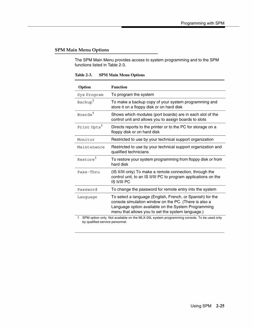
Programming with SPM
Using SPM 2-25
SPM Main Menu Options 2
The SPM Main Menu provides access to system programming and to the SPM functions listed in Table 2-3.
Table 2-3. SPM Main Menu Options
Option Function
Sys Program To program the system
Backup1
1 SPM option only. Not available on the MLX-20L system programming console. To be used only by qualified service personnel.
To make a backup copy of your system programming and store it on a floppy disk or on hard disk
Boards1 Shows which modules (port boards) are in each slot of the control unit and allows you to assign boards to slots
Print Opts1 Directs reports to the printer or to the PC for storage on a floppy disk or on hard disk
Monitor Restricted to use by your technical support organization
Maintenance Restricted to use by your technical support organization and qualified technicians
Restore1 To restore your system programming from floppy disk or from hard disk
Pass-Thru (IS II/III only) To make a remote connection, through the control unit, to an IS II/III PC to program applications on the IS II/III PC
Password To change the password for remote entry into the system
Language To select a language (English, French, or Spanish) for the console simulation window on the PC. (There is also a Language option available on the System Programming menu that allows you to set the system language.)
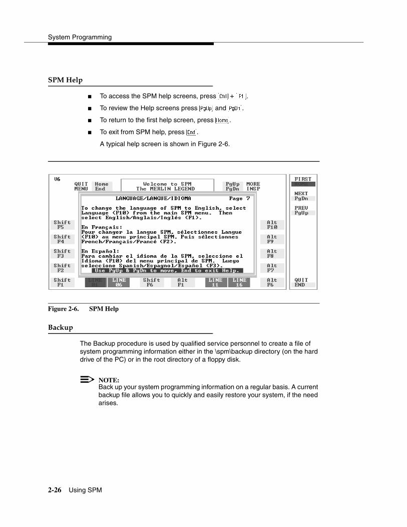
System Programming
2-26 Using SPM
SPM Help 2
� To access the SPM help screens, press ���.
� To review the Help screens press � and �.
� To return to the first help screen, press �.
� To exit from SPM help, press �.
A typical help screen is shown in Figure 2-6.
Figure 2-6. SPM Help
Backup 2
The Backup procedure is used by qualified service personnel to create a file of system programming information either in the \spm\backup directory (on the hard drive of the PC) or in the root directory of a floppy disk.
NOTE:Back up your system programming information on a regular basis. A current backup file allows you to quickly and easily restore your system, if the need arises.

Programming with SPM
Using SPM 2-27
Determining the Release Number of a Backup File 2
If you have a backup disk but do not know its release number, you may be able to find this information in the backup header.
Beginning with later versions of Release 1.1, the backup file contains a backup header 128 bytes long. Approximately 59 of these bytes are currently used. Bytes 55 through 59 of the header contain the MERLIN LEGEND Communication System Release number, as shown in Table 2-4. (Release 1.0 and early versions of Release 1.1 do not contain this information in readable form.)
The release number is found in the first two bytes (four characters) of the identification number—for example, 0600 = 6.0, 0402 = 4.2.
If the backup file is compressed (Release 1.1 and later), you can read the header but you cannot read the data area following the header. Use type [backup filename] to read the header on a DOS system or cat [backup filename] to read the header on a UNIX System.
Note that it is the communication system release number, not the version number of SPM, that reflects whether the backup file is compressed or uncompressed. Release 1.0 backups are uncompressed and Release 1.1 and later backups are compressed. Uncompressed files take longer to restore.
Considerations 2
Review the following items before you begin the backup procedure:
� The communications system does not have to be idle during backup; however, extension programming is blocked.
� Any objects that are in a maintenance-busy state are stored in that state. When you restore system programming, these objects are busied out, even if they have since been released from the maintenance-busy state.
Table 2-4. Backup Header: Release Number
Release No. Build No. System Size Mode
Size 2 bytes 12 bytes 1 byte 1 byte
Examples 06 00 32 01 01 (Key)
04 02 02 (Behind Switch)
03 (Hybrid/PBX)

System Programming
2-28 Using SPM
� If you plan to store your backup file on a floppy disk, format a DOS disk. (DOS formatting can be done on either a UNIX System PC or a DOS PC).
� Uncompressed backup files are 100,000 to 210,000 bytes in size; compressed files are about 70,000 to 85,000 bytes.
� Maintenance data (error logs and other data used by qualified service technicians) is not saved in the backup file.
To perform the backup procedure, follow the steps below:
1. At the SPM Main Menu, press � to select Backup.
2. Follow the instructions for a floppy or a hard disk.
A second window appears, which displays the GOTO FLOPPY and MAKE NEW FILE options and a directory listing for the C:\spm\backup directory.
� If you are saving the backup file to a floppy disk, go to Step 3.
� If you are saving the backup file to the hard disk, go to Step 4.
3. Remove the SPM disk from the floppy drive and insert a formatted disk. Use the arrow keys to highlight GOTO FLOPPY and press �.
After you press �, the GOTO FLOPPY statement shown above changes to GOTO HARD DISK and the directory listing for A:\ is displayed. Continue with Step 4.
The screen displays the default name for the backup file (backup.ams).
SPM Main Menu
Menu: Select Function
Sys Program Maintenance
Backup Restore
Boards Pass-Thru
Print Opts Password
Monitor Language
Make a selection for GOTO FLOPPY
the BACKUP file. MAKE NEW FILE
MAKE NEW FILE will backup.ams
create a new file file.1
on selected device. file.2
Press ESC to abort.
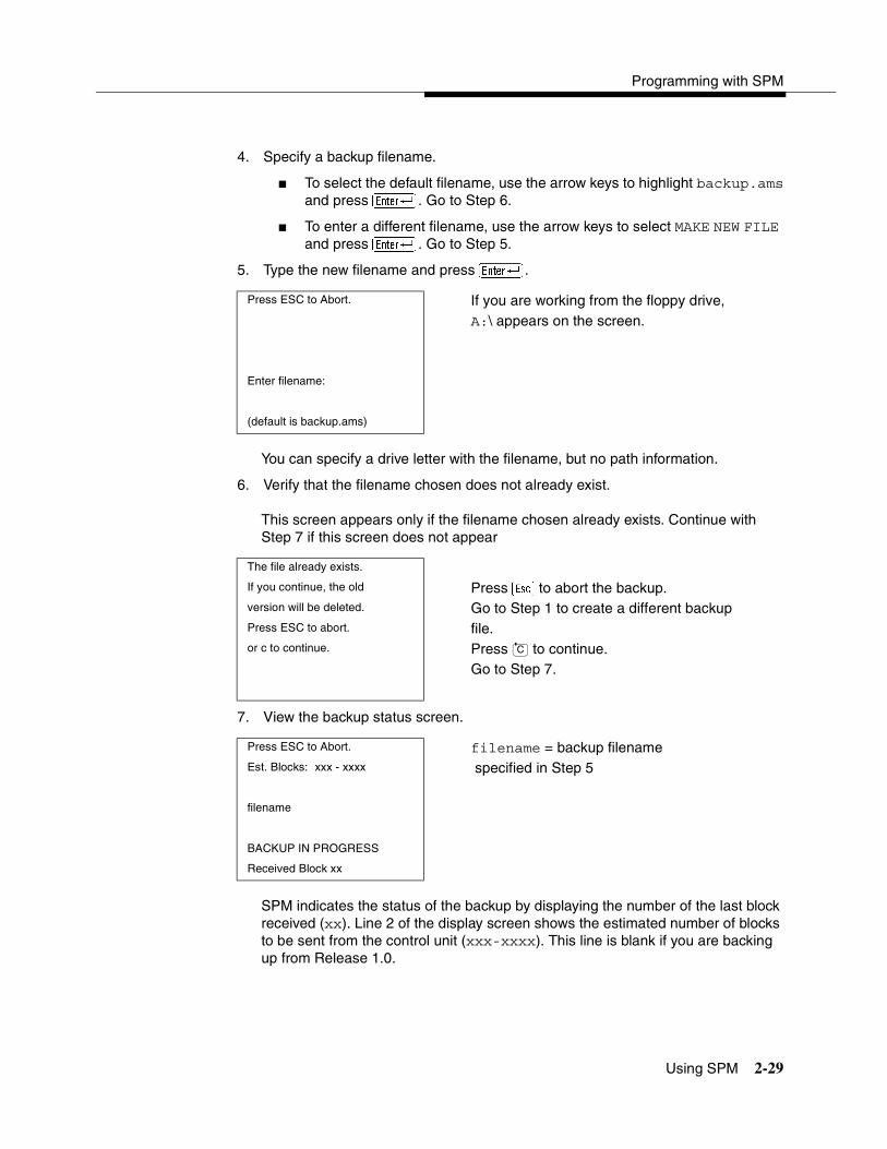
Programming with SPM
Using SPM 2-29
4. Specify a backup filename.
� To select the default filename, use the arrow keys to highlight backup.amsand press �. Go to Step 6.
� To enter a different filename, use the arrow keys to select MAKE NEW FILE and press �. Go to Step 5.
5. Type the new filename and press �.
You can specify a drive letter with the filename, but no path information.
6. Verify that the filename chosen does not already exist.
This screen appears only if the filename chosen already exists. Continue with Step 7 if this screen does not appear
7. View the backup status screen.
SPM indicates the status of the backup by displaying the number of the last block received (xx). Line 2 of the display screen shows the estimated number of blocks to be sent from the control unit (xxx-xxxx). This line is blank if you are backing up from Release 1.0.
Press ESC to Abort. If you are working from the floppy drive,A:\ appears on the screen.
Enter filename:
(default is backup.ams)
The file already exists.
If you continue, the old Press � to abort the backup. version will be deleted. Go to Step 1 to create a different backup Press ESC to abort. file.or c to continue. Press to continue.
Go to Step 7.
Press ESC to Abort. filename = backup filename Est. Blocks: xxx - xxxx specified in Step 5
filename
BACKUP IN PROGRESS
Received Block xx
C
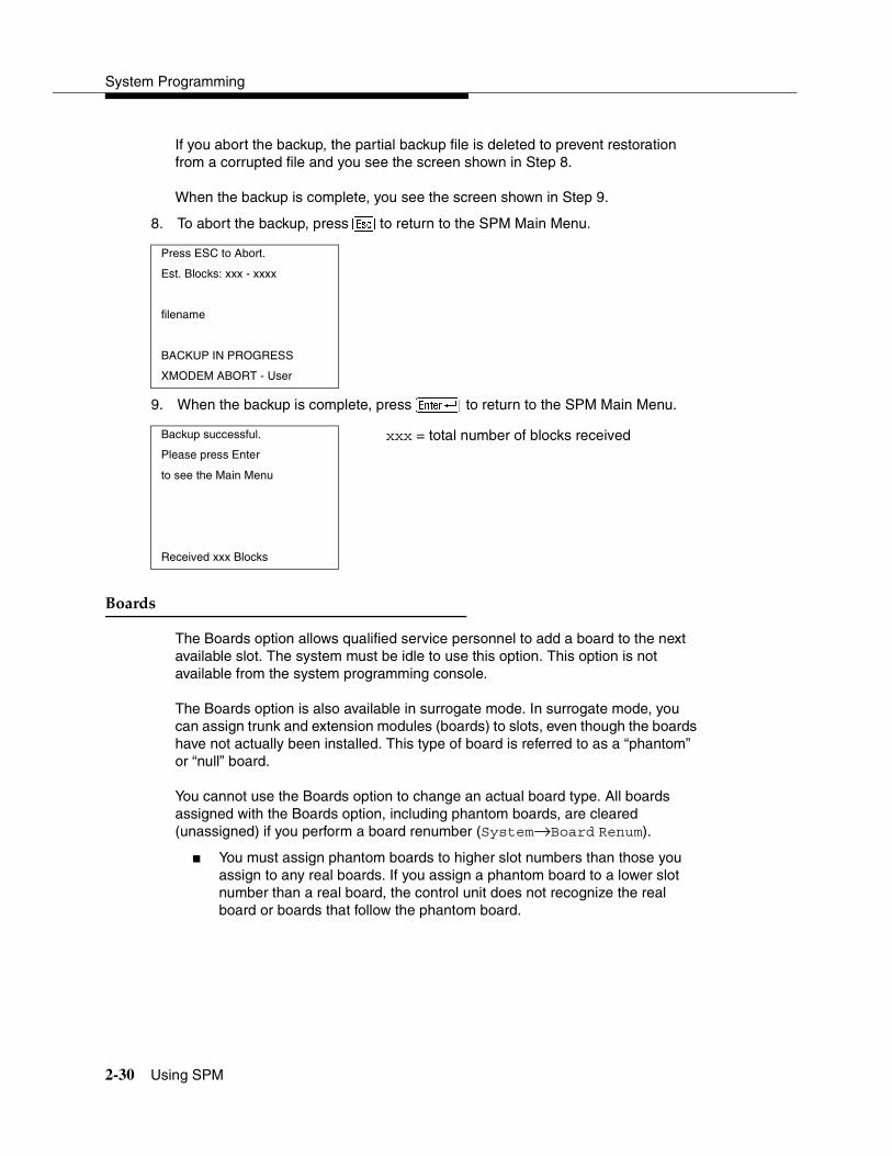
System Programming
2-30 Using SPM
If you abort the backup, the partial backup file is deleted to prevent restoration from a corrupted file and you see the screen shown in Step 8.
When the backup is complete, you see the screen shown in Step 9.
8. To abort the backup, press � to return to the SPM Main Menu.
9. When the backup is complete, press � to return to the SPM Main Menu.
Boards 2
The Boards option allows qualified service personnel to add a board to the next available slot. The system must be idle to use this option. This option is not available from the system programming console.
The Boards option is also available in surrogate mode. In surrogate mode, you can assign trunk and extension modules (boards) to slots, even though the boards have not actually been installed. This type of board is referred to as a “phantom” or “null” board.
You cannot use the Boards option to change an actual board type. All boards assigned with the Boards option, including phantom boards, are cleared (unassigned) if you perform a board renumber (System→Board Renum).
� You must assign phantom boards to higher slot numbers than those you assign to any real boards. If you assign a phantom board to a lower slot number than a real board, the control unit does not recognize the real board or boards that follow the phantom board.
Press ESC to Abort.
Est. Blocks: xxx - xxxx
filename
BACKUP IN PROGRESS
XMODEM ABORT - User
Backup successful. xxx = total number of blocks receivedPlease press Enter
to see the Main Menu
Received xxx Blocks

Programming with SPM
Using SPM 2-31
� If you remove a board but do not replace it, and then perform a board renumber, the control unit will not recognize any boards that follow the empty slot. You must reseat all of the boards to fill the empty slot before you perform the board renumber.
The Inspect function (�) lets you see which modules have been assigned to slots on the control unit. Note that both phantom boards and real boards display if you use the Inspect function. Table 2-5 shows the type of boards that you can select. To see only real board assignments, you must print the System Information report: System→More→Print→SysSet-up.
Table 2-5. Board Types
Board Type Description
400LSR 4 loop-start line jacks with 4 touch-tone receivers
400GLR 4 ground-start/loop-start line jacks with 4 touch-tone receivers
800LS 8 loop-start line jacks
800GLID 8 ground-start/loop-start line jacks with Caller ID capability available on the loop-start lines and 2 touch-tone receivers
800GLS 8 ground-start/loop-start line jacks
408LSA 4 loop-start line jacks and 8 ATL analog extension jacks
408GLA 4 ground-start/loop-start line jacks and 8 ATL analog extension jacks
408GLM 4 ground-start/loop-start line jacks and 8 MLX extension jacks (16 endpoints)
408GLM-U 4 ground-start/loop-start line jacks and 8 MLX extension jacks (16 endpoints); Caller ID; Upgradable with PCMCIA card
008ATL 8 analog extension jacks
008MLX 8 MLX extension jacks (16 endpoints)
008MLX-U 8 MLX extension jacks (16 endpoints); Upgradable with PCMCIA card
016MLX 16 MLX extension jacks (32 endpoints)
016MLX-U 16 MLX extension jacks (32 endpoints); Upgradable with PCMCIA card
012TR/OPT 12 tip/ring extension jacks with 2 touch-tone receivers or 008 OPT jacks
016TRR 16 tip/ring extension jacks with 4 touch-tone receivers

System Programming
2-32 Using SPM
Follow the steps below to assign modules:
1. At the SPM Main Menu, press � to select Boards.
2. Press the function key that corresponds to the module you want to select.
412LS/ETR 4 loop-start line jacks with Caller ID capability with 2 touch-tone receivers and 12 ETR extension jacks including 4 with tip/ring functionality
016ETR 16 ETR extension jacks including 6 with tip/ring functionality with 4 touch-tone receivers
800DID 8 DID trunk jacks with 2 touch-tone receivers
400E&M 4 E&M tie trunk jacks
100D 1 DS1 jack (24 channels) (Prior to Release 7.0, Common Channel Signaling (CCS) was an option for T1; for Release 7.0 and later systems, CCS is not an option for T1.)
100D-U 1 DS1 jack (24 channels); Upgradable with PCMCIA card
800BRI 8 BRI trunk jacks (16 channels)
SPM Main Menu
Menu: Select Function
Sys Program Maintenance
Backup Restore
Boards Pass-Thru
Print Opts Password
Monitor Language
Boards: >
Make a selection
408LSA 800LS
012TR/OPT 008ATL
800DID 008MLX
800GLS 400GLR
Exit 400LSR
Table 2-5. Board Types—Continued
Board Type Description

Programming with SPM
Using SPM 2-33
3. If the module you want to assign is not shown on the first screen of the Boards menu, press � to display the next menu screen.
NOTE:The 408GLM module does not provide Caller ID; the 408GLM-U for Release 2.5 or later provides Caller ID.
4. If the module you want to assign is not shown on the second screen of the Boards menu, press � to display the next menu screen.
5. Type the control unit slot number (01 through 17) in which the module is to be installed.
Boards:
Make a selection
400E&M 800GLID
408GLA 016TRR
100D 800BRI
408GLM 408GLM-U
Exit 008MLX-U
Boards:
Make a selection
100D-U
016MLX-U
412LS/ETR
016ETR
Exit
module name module name = option selected in Step 2Enter slot numbers
(01–17)
Delete
Backspace Next
Exit Enter

System Programming
2-34 Using SPM
6. Assign or remove the module from the slot entered in previous Step.
� To remove the module type from the specified slot number, select (Delete). The Boards menu reappears.
� To assign the module type to the specified slot number and assign that same module type to another slot, select � (Next).
� To assign the module type to the specified slot number and assign a different module type to another slot, select � (Enter).
� To terminate the procedure and assign a different module, select � (Exit) and repeat Steps 2 through 4.
� To view types of modules assigned to all slots, select � (Inspect).
7. To save your entry, select Exit.
The programming session terminates and the system restarts.
Browse 2
The Browse option allows you to browse through reports saved in the Reports directory (\spm\reports) on the hard disk of the PC or on a floppy.
1. From any screen, press �� to activate the Browse option.
module name module name = option selected in Step 2Enter slot numbers
(01–17) nn = slot entered in Step 5nn
Delete
Backspace Next
Exit Enter
SPM Main Menu
Menu: Select Function
Sys Program Maintenance
Backup Restore
Boards Pass-Thru
Print Opts Password
Monitor Language

Programming with SPM
Using SPM 2-35
2. Use the arrow keys to highlight the source (hard disk or floppy) from which you want to view the reports and press �.
A list of the current reports appears:
� FILENAME.XXX and FILENAME.YYY are from the \spm\reports directory of the hard disk.
3. Use the arrow keys to highlight the report you want to view and press �.
The report appears.
� To view the next page of a report, press �.
� To view the previous page of a report, press �.
� To return to the beginning of a report, press �.
� To exit from the Browse option and return to the SPM Main Menu, press �.
Convert 2
The Convert option (which can be used remotely) simplifies upgrading from an earlier release to a current release of the communications system. See ‘‘Upgrading the System’’ on page 2-57. This procedure should be done only by Lucent Technologies personnel or your authorized dealer.
To convert system programming to Release 7.0 format, version 7.15 or later of SPM is required. This version can be easily identified by the version number that appears on the last line of the console simulation window.
Help screens are available to guide you through the Convert procedure. See ‘‘SPM Help’’ on page 2-26.
GOTOFLOPPY
Please enter file name FILENAME.XXX
FILENAME.XXX
Press ESC to Abort.
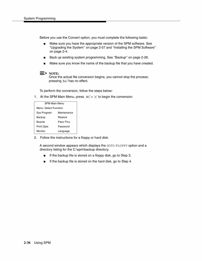
System Programming
2-36 Using SPM
Before you use the Convert option, you must complete the following tasks:
� Make sure you have the appropriate version of the SPM software. See ‘‘Upgrading the System’’ on page 2-57 and ‘‘Installing the SPM Software’’ on page 2-4.
� Back up existing system programming. See ‘‘Backup’’ on page 2-26.
� Make sure you know the name of the backup file that you have created.
NOTE:Once the actual file conversion begins, you cannot stop the process; pressing � has no effect.
To perform the conversion, follow the steps below:
1. At the SPM Main Menu, press � + � to begin the conversion.
2. Follow the instructions for a floppy or hard disk.
A second window appears which displays the GOTO FLOPPY option and a directory listing for the C:\spm\backup directory.
� If the backup file is stored on a floppy disk, go to Step 3.
� If the backup file is stored on the hard disk, go to Step 4.
SPM Main Menu
Menu: Select Function
Sys Program Maintenance
Backup Restore
Boards Pass-Thru
Print Opts Password
Monitor Language
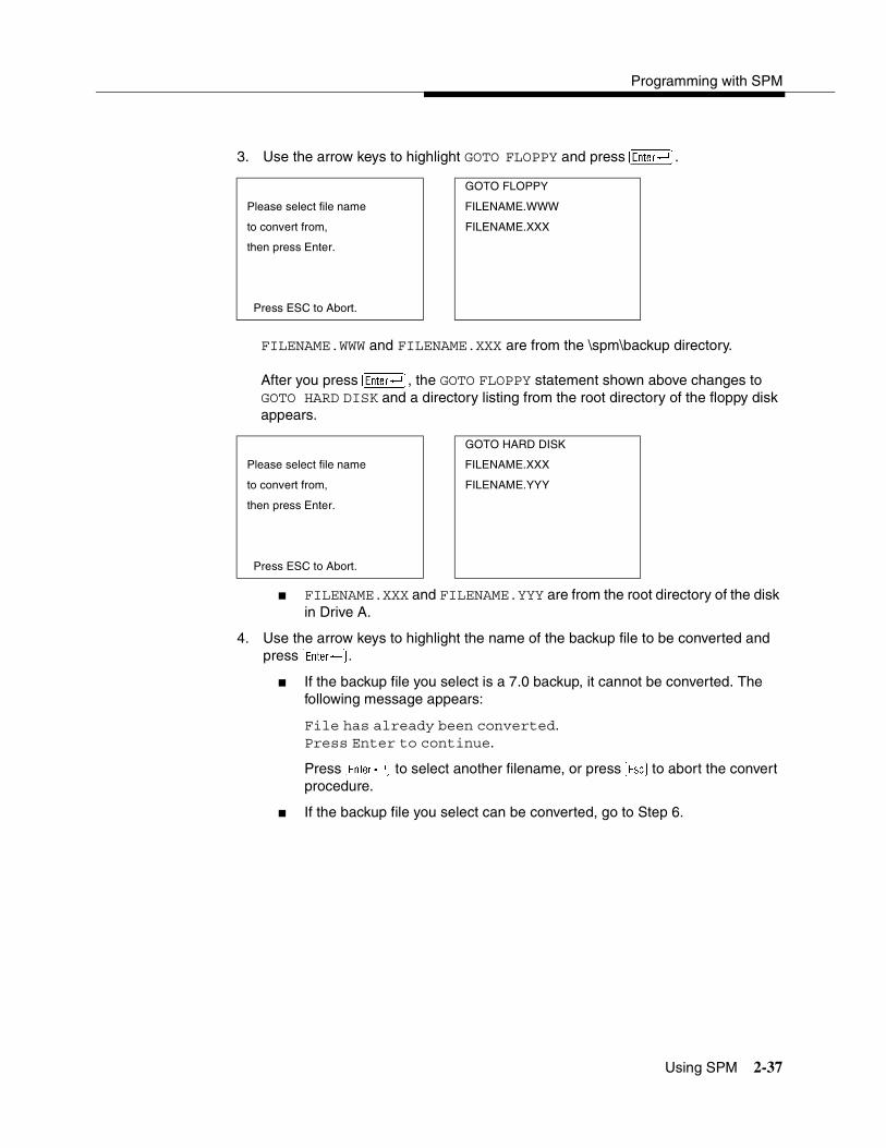
Programming with SPM
Using SPM 2-37
3. Use the arrow keys to highlight GOTO FLOPPY and press �.
FILENAME.WWW and FILENAME.XXX are from the \spm\backup directory.
After you press �, the GOTO FLOPPY statement shown above changes to GOTO HARD DISK and a directory listing from the root directory of the floppy disk appears.
� FILENAME.XXX and FILENAME.YYY are from the root directory of the disk in Drive A.
4. Use the arrow keys to highlight the name of the backup file to be converted and press �.
� If the backup file you select is a 7.0 backup, it cannot be converted. The following message appears:
File has already been converted.Press Enter to continue.
Press � to select another filename, or press � to abort the convert procedure.
� If the backup file you select can be converted, go to Step 6.
GOTO FLOPPY
Please select file name FILENAME.WWW
to convert from, FILENAME.XXX
then press Enter.
Press ESC to Abort.
GOTO HARD DISK
Please select file name FILENAME.XXX
to convert from, FILENAME.YYY
then press Enter.
Press ESC to Abort.
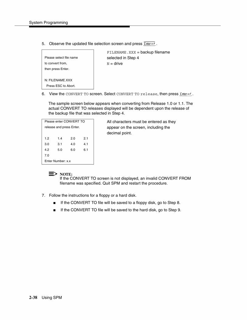
System Programming
2-38 Using SPM
5. Observe the updated file selection screen and press �.
6. View the CONVERT TO screen. Select CONVERT TO release, then press �.
The sample screen below appears when converting from Release 1.0 or 1.1. The actual CONVERT TO releases displayed will be dependent upon the release of the backup file that was selected in Step 4.
NOTE:If the CONVERT TO screen is not displayed, an invalid CONVERT FROM filename was specified. Quit SPM and restart the procedure.
7. Follow the instructions for a floppy or a hard disk.
� If the CONVERT TO file will be saved to a floppy disk, go to Step 8.
� If the CONVERT TO file will be saved to the hard disk, go to Step 9.
FILENAME.XXX = backup filenamePlease select file name selected in Step 4to convert from, N = drivethen press Enter.
N: FILENAME.XXX
Press ESC to Abort.
Please enter CONVERT TO All characters must be entered as they release and press Enter. appear on the screen, including the
decimal point.1.2 1.4 2.0 2.1
3.0 3.1 4.0 4.1
4.2 5.0 6.0 6.1
7.0
Enter Number: x.x
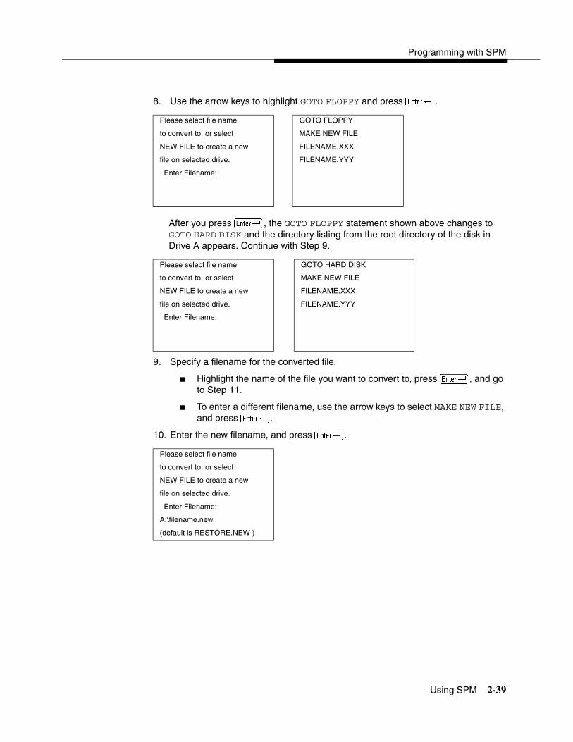
Programming with SPM
Using SPM 2-39
8. Use the arrow keys to highlight GOTO FLOPPY and press �.
After you press �, the GOTO FLOPPY statement shown above changes to GOTO HARD DISK and the directory listing from the root directory of the disk in Drive A appears. Continue with Step 9.
9. Specify a filename for the converted file.
� Highlight the name of the file you want to convert to, press �, and go to Step 11.
� To enter a different filename, use the arrow keys to select MAKE NEW FILE, and press �.
10. Enter the new filename, and press �.
Please select file name GOTO FLOPPY
to convert to, or select MAKE NEW FILE
NEW FILE to create a new FILENAME.XXX
file on selected drive. FILENAME.YYY
Enter Filename:
Please select file name GOTO HARD DISK
to convert to, or select MAKE NEW FILE
NEW FILE to create a new FILENAME.XXX
file on selected drive. FILENAME.YYY
Enter Filename:
Please select file name
to convert to, or select
NEW FILE to create a new
file on selected drive.
Enter Filename:
A:\filename.new
(default is RESTORE.NEW )
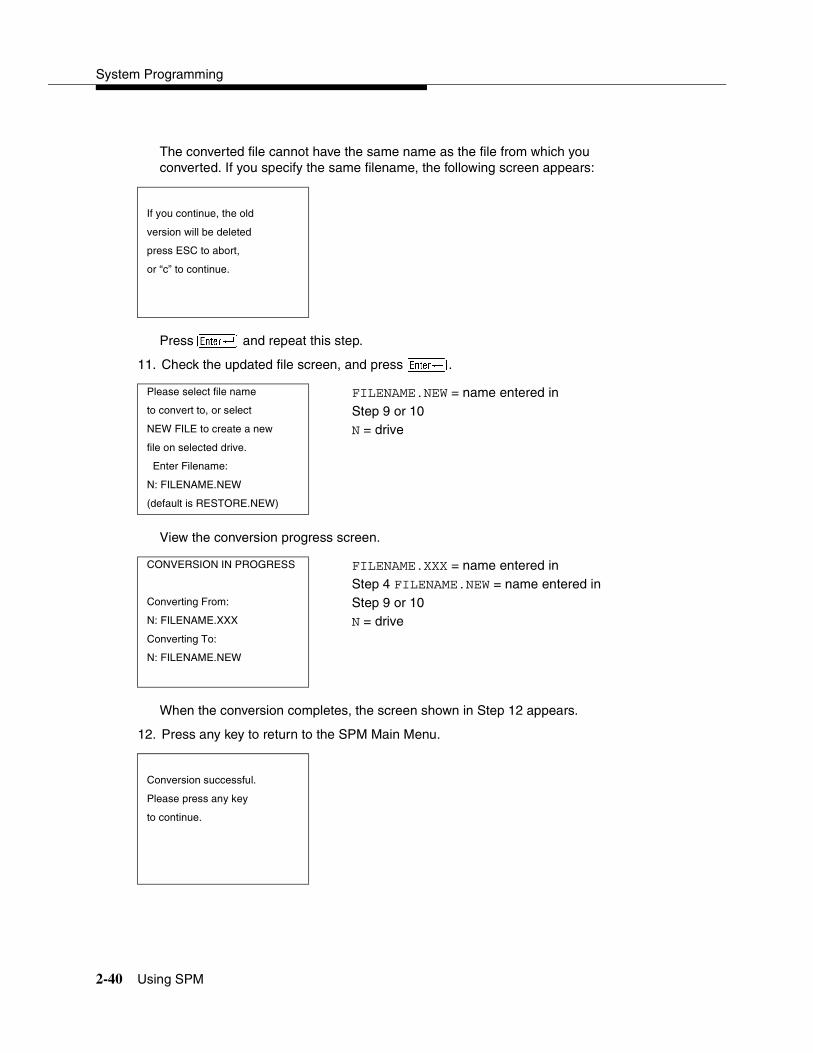
System Programming
2-40 Using SPM
The converted file cannot have the same name as the file from which you converted. If you specify the same filename, the following screen appears:
Press � and repeat this step.
11. Check the updated file screen, and press �.
View the conversion progress screen.
When the conversion completes, the screen shown in Step 12 appears.
12. Press any key to return to the SPM Main Menu.
If you continue, the old
version will be deleted
press ESC to abort,
or “c” to continue.
Please select file name FILENAME.NEW = name entered in to convert to, or select Step 9 or 10NEW FILE to create a new N = drivefile on selected drive.
Enter Filename:
N: FILENAME.NEW
(default is RESTORE.NEW)
CONVERSION IN PROGRESS FILENAME.XXX = name entered in Step 4 FILENAME.NEW = name entered in
Converting From: Step 9 or 10N: FILENAME.XXX N = driveConverting To:
N: FILENAME.NEW
Conversion successful.
Please press any key
to continue.
Programming with SPM
Using SPM 2-41
Language 2
A language attribute in the SPM configuration file \spm\ams.cfg (DOS version) or /usr/ams/ams.cfg (UNIX System version) specifies whether SPM menus, pop-up windows, and other messages are presented in English, French, or Spanish. A second language selection option affects messages from the control unit to SPM, and controls the display on the console simulation window for the duration of the session. These two language options operate independently of each other.
The following discussion refers to the language specified in the SPM configuration file as the PC language and the language used by the control unit as the console window language.
PC Language 2
During SPM installation, you select a language that is recorded in the SPM configuration file. Any time thereafter, SPM can be started with the -l option to specify a different language, using one of the following command lines:
� spm-l english
� spm-l french
� spm-l spanish
NOTE:The option is a lowercase letter “l” and not the number “1”.
Use of the -l option changes the language attribute in the ams.cfg file. The language specified becomes the new PC language, used whenever SPM is started without the -l option.
Console Window Language 2
By default, the language used in the console simulation window is the language specified in the ams.cfg file; however, you can select a different language for this window for the duration of the current session.

System Programming
2-42 Using SPM
To select a different language for the current session, follow the steps below:
1. At the SPM Main Menu, press � to select Language.
2. Press the function key that corresponds to your language selection.
The Display Language screen reappears with the language you selected.
3. Press � to return to the SPM Main Menu or select another language.
Maintenance 2
! CAUTION:This option is for use by qualified technicians only. Maintenance procedures are provided in the documentation for qualified technicians. See ‘‘Related Documents’’ on page lxxi.
! CAUTION:This is a password-protected option and is for use by your technical support organization only.
SPM Main Menu
Menu: Select Function
Sys Program Maintenance
Backup Restore
Boards Pass-Thru
Print Opts Password
Monitor Language
Display Language
Make a Selection:
English
French
Spanish
Exit

Programming with SPM
Using SPM 2-43
Pass-Thru 2
The Pass-Thru option allows qualified service personnel to program IS II/III1 applications on a remote PC. It permits you to establish a remote connection with the control unit to which the IS II/III PC is directly connected. Figure 2-7 illustrates the relationship of the SPM PC, the communications system control unit, and the IS II/III PC.
Figure 2-7. Pass-Thru
A Pass-Thru request must be initiated at a DOS PC; it is not available from a UNIX System PC—that is, Pass-Thru cannot be established between two IS II/III PCs. The local admin PC must be in an idle state.
A Pass-Thru request to a locally connected IS II/III system causes the modem to fall back to 1200 bps if the speed is set to 2400 bps and the modem call to the control unit is at 1200 bps. If necessary, the communications system adjusts its speed to that of the local SPM PC.
Once the Pass-Thru connection is established, you can program in any of the following IS II/III applications from your SPM PC:
� AUDIX Voice Power™1
� Call Accounting System2
� Fax Attendant System (IS III only)
� CONVERSANT Intro (IS III only)
1 Can no longer be ordered.
2 Can be ordered only as an upgrade to existing CAS installations.
CAUTION
POWER
ON
OFF
AG INPUTAG INPUT
FRFR
GNDGND
Turn offpower beforeinserting orremovingmodules
408
GS
/LS
44G
S o
r LS
Out
side
Lin
es/
8 A
nalo
g Te
leph
ones
(ATL
)
408 00
8 M
LX8
MLX
(Dig
ital)
Tele
phon
es
012
PR
OC
ES
SO
R
SPM PCControl UnitIS II/III PC
Direct Connection
RemoteConnection

System Programming
2-44 Using SPM
NOTE:You cannot program the SPM application on the IS II/III PC because the remote call (from your SPM PC) uses the IS II/III PC’s COM1 port; therefore, the system programming jack cannot be used for system programming. For the same reason, a user at the IS II/III PC end of the connection cannot use SPM while your Pass-Thru is in effect. If use of SPM is attempted, the user at the IS II/III end sees the following message:
PRE-EMPT IN PROGRESSPlease try again.
To initiate Pass-Thru, establish a modem connection between the SPM PC and the control unit.
If the IS II/III PC does not respond to the Pass-Thru request from the control unit (for example, because the PC is turned off), you see the following message:
Pass-thru failed.Please try again.
If the connection between the control unit and the IS II/III PC fails, the connection between the control unit and the SPM PC is dropped. You see the following message:
Pass-through Sessionunexpectedly terminated.Please press Enterto continue.
When you press �, you return to the SPM Main Menu.
To initiate the Pass-Thru, follow the steps below:
1. At the SPM Main Menu, press to select Pass-Thru.
The display area changes to 24-lines by 80-characters, which is much larger than the display area on the console simulation window (7-lines by 24-characters).
SPM Main Menu
Menu: Select Function
Sys Program Maintenance
Backup Restore
Boards Pass-Thru
Print Opts Password
Monitor Language
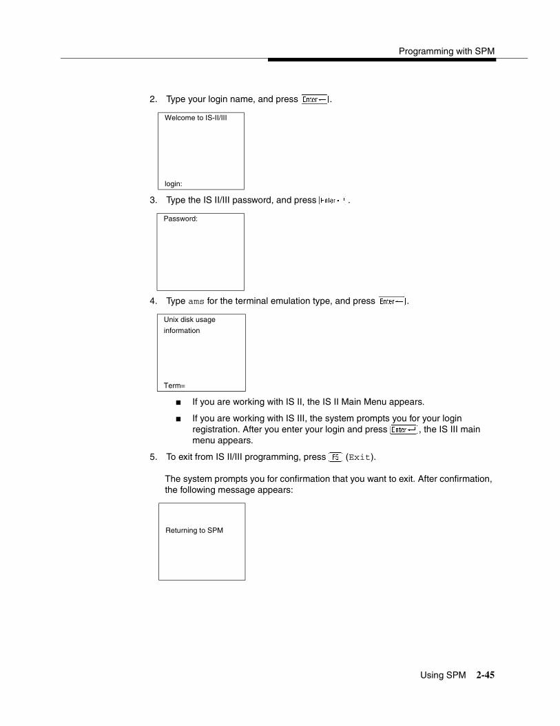
Programming with SPM
Using SPM 2-45
2. Type your login name, and press �.
3. Type the IS II/III password, and press �.
4. Type ams for the terminal emulation type, and press �.
� If you are working with IS II, the IS II Main Menu appears.
� If you are working with IS III, the system prompts you for your login registration. After you enter your login and press �, the IS III main menu appears.
5. To exit from IS II/III programming, press � (Exit).
The system prompts you for confirmation that you want to exit. After confirmation, the following message appears:
Welcome to IS-II/III
login:
Password:
Unix disk usage
information
Term=
Returning to SPM

System Programming
2-46 Using SPM
Password 2
The Password option is used by qualified service personnel to change the modem connection password. A password is always required to establish a connection with the built-in modem. The password always consists of seven characters. You can perform remote system programming only if you enter the password correctly. A default password is set at the factory. You must obtain this password from your system consultant (SC).
To change the modem connection password, follow the steps below:
1. At the SPM Main Menu, press � to select Password.
2. Type the old (current) password. Do not press �.
If you type the old password incorrectly, the bottom of the screen displays the message, Not Equal. Repeat Step 2.
If you fail to enter the password correctly after three attempts, the bottom of the screen displays the message Old Password in Use, and the procedure terminates. Press � to return to the SPM Main Menu.
SPM Main Menu
Menu: Select Function
Sys Program Maintenance
Backup Restore
Boards Pass-Thru
Print Opts Password
Monitor Language
Password:
Enter Old Password

Programming with SPM
Using SPM 2-47
3. Type the new password (any seven characters). Do not press �
! SECURITY ALERT:The password does not appear on the screen as you type it.
Always use the longest length password allowed on the system.
Passwords should consist of a random, non-repetitive, hard-to-guess sequence of characters.
4. Type the new password again. Do not press �.
5. To return to the SPM Main Menu, press �.
Print Options 2
The Print Opts option allows qualified service personnel to direct the output of system programming reports either to the PC (where you can save them, browse through them, or print them with the system programming Print option) or to the SMDR printer.
Password
Enter New Password
Password
Enter New Password again
New Password in use

System Programming
2-48 Using SPM
To direct the output of the system programming reports, follow the steps below:
1. At the SPM Main Menu, press to select Print Opts.
2. Select the target device for the reports.
3. To return to the SPM Main Menu, press �.
SMDR Port Output 2
See ‘‘Printing System Reports’’ on page 3-224 for more information about the print procedure using the system console and the SMDR port.
PC Port Output 2
See ‘‘Printing Reports’’ on page 2-55 for more information about the print procedure using SPM and the PC port.
Restore 2
The Restore option allows qualified service personnel to load system programming from either a disk or from the hard disk into the processor module memory.
This procedure is used either to program a new system if a disk was created through surrogate mode programming, or to restore information (using a backup disk) lost through system failure. It is also part of the upgrade procedure.
SPM Main Menu
Menu: Select Function
Sys Program Maintenance
Backup Restore
Boards Pass-Thru
Print Opts Password
Monitor Language
Printer Options
Make a selection
SMDR Port
PC Port
Exit

Programming with SPM
Using SPM 2-49
Considerations 2
Review the following items before you begin the restore procedure:
� The system will be forced idle during a restore procedure.
� You must have a backup file containing system programming before you use this procedure. See ‘‘Backup’’ on page 2-26.
� Features that were not programmed when the backup file was created are reset to factory settings.
� The data restored reflects the number of extensions and lines available on the system at the time the backup was created. The remaining extensions and lines are set to the factory settings that are initialized during a Restart (cold start).
� Restore is terminated under the following conditions:
— If fewer boards are listed on the backup disk than on the control unit.
— If any real board is out of sequence with the boards listed on the backup disk.
— If phantom boards are not listed last.
— If the operating mode of the system being restored is Hybrid/PBX, but the control unit processor module has been modified to operate only in Key mode.
� A successful restore is followed automatically by a Restart (cold start).
! WARNING:An unsuccessful or terminated restore results in a System Erase (frigid start). All calls are dropped. The system configuration is erased. All system programming is lost and the system returns to the factory settings. If the restore is being done remotely, the connection is dropped immediately. If this happens, attempt to reconnect to the control unit and immediately perform another restore. If this is not successful, programming must be restored on site.

System Programming
2-50 Using SPM
To perform a restore, follow the steps below:
1. At the SPM Main Menu, press � to select Restore.
2. Follow the instructions for a floppy or a hard disk.
A second window appears which displays the GOTO FLOPPY option and a directory listing for C:\spm\backup.
� If you are performing a Restore with a file saved on a floppy disk, go to Step 3.
� If you are performing a Restore with a file saved on the hard disk, go to Step 4.
3. Use the arrow keys to highlight GOTO FLOPPY and press �.
After you press �, the GOTO FLOPPY statement shown above changes to GOTO HARD DISK. Go to Step 5.
4. Specify the filename from which to restore.
� To select the default backup filename, use the arrow keys to highlight backup.ams and press �.
� If you used a different backup filename, use the arrow keys to select one of the other filenames and press �.
SPM Main Menu
Menu: Select Function
Sys Program Maintenance
Backup Restore
Boards Pass-Thru
Print Opts Password
Monitor Language
Make a selection for GOTO FLOPPY
the RESTORE file. backup.ams
file.1
If upgrading, convert file.2
files before restoring.
Press ESC to Abort.
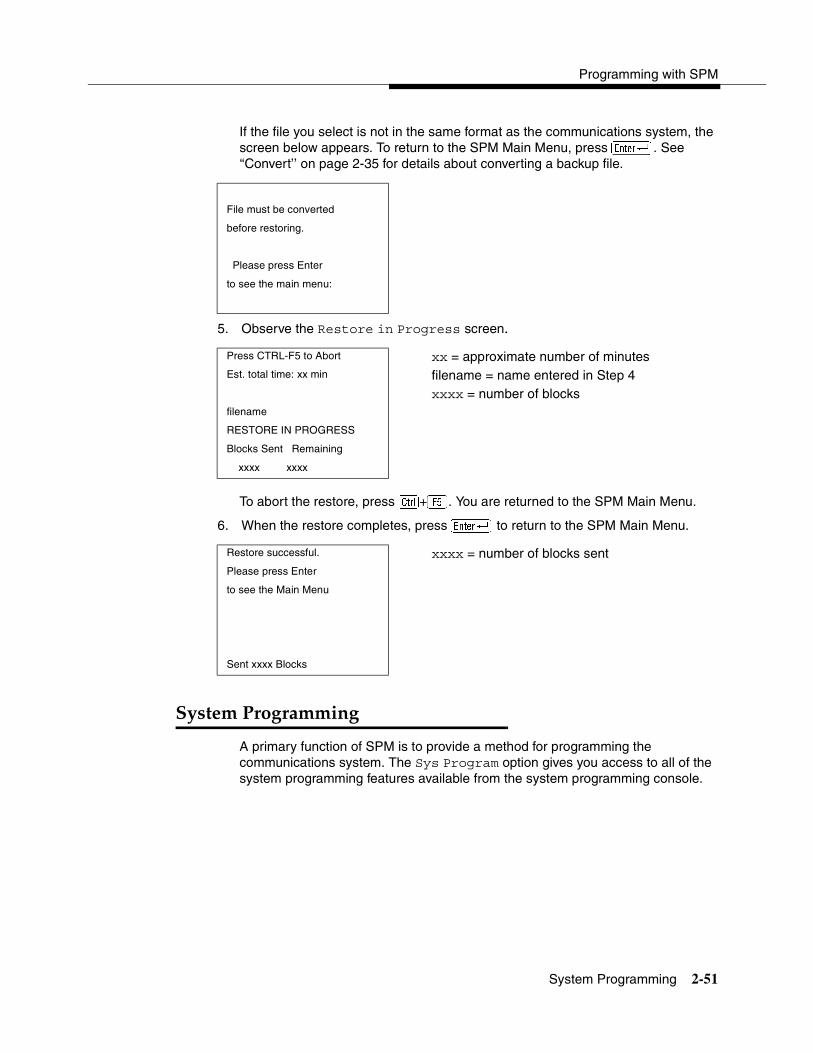
Programming with SPM
System Programming 2-51
If the file you select is not in the same format as the communications system, the screen below appears. To return to the SPM Main Menu, press �. See ‘‘Convert’’ on page 2-35 for details about converting a backup file.
5. Observe the Restore in Progress screen.
To abort the restore, press �+�. You are returned to the SPM Main Menu.
6. When the restore completes, press � to return to the SPM Main Menu.
System Programming 2
A primary function of SPM is to provide a method for programming the communications system. The Sys Program option gives you access to all of the system programming features available from the system programming console.
File must be converted
before restoring.
Please press Enter
to see the main menu:
Press CTRL-F5 to Abort xx = approximate number of minutesEst. total time: xx min filename = name entered in Step 4
xxxx = number of blocksfilename
RESTORE IN PROGRESS
Blocks Sent Remaining
xxxx xxxx
Restore successful. xxxx = number of blocks sentPlease press Enter
to see the Main Menu
Sent xxxx Blocks
System Programming
2-52 System Programming
Basic Programming Information 2
To begin programming, you must perform one of the following to display the System Programming menu on the MLX-20L console or PC:
In most cases, you can press Exit or � to exit from a screen without making any changes. Exceptions to this are noted as part of a procedure. When you complete a procedure and press Exit (�), you usually move up one screen in the menu hierarchy. Occasionally, when you press Exit (�), you return to the previous screen. In a few cases, pressing Exit brings you back to the System Programming menu, where you can select another option to program or exit from system programming.
To complete a procedure and save the information you have programmed, press Enter (�).
If you are programming a group of sequentially numbered extensions or trunks, you may have the option of pressing Next (). This saves your entry and automatically provides the number of the next extension or trunk in the sequence, thus saving you a couple of steps. If Next displays on the screen, you can use it with the current option.
In most cases, you will be at an intermediate step in the procedure you have just completed. At that point, you can select one of the options shown on the screen and continue programming, or you can press Exit (�) again. This usually takes you back to the System Programming menu. If not, you again can continue programming on the current screen or press Exit (�) again.
Idle States 2
A few of the programming procedures can be started only when the entire system or some part of it, such as a trunk or an extension, is idle (not in use). Some procedures require that the trunk or extension be idle only at the instant of programming. Other procedures, which take longer, require the system, trunk, or extension to be forced to remain idle until programming is completed. These procedures wait for the system, trunk, or extension to become idle and then prevent the initiation of any new calls. This condition is called forced idle.
NOTE:If a procedure requires an idle condition, perform the programming outside of normal business hours.
On the console: Menu→Sys Program →Exit
On the PC: Type spm →�→Press any key→�→�
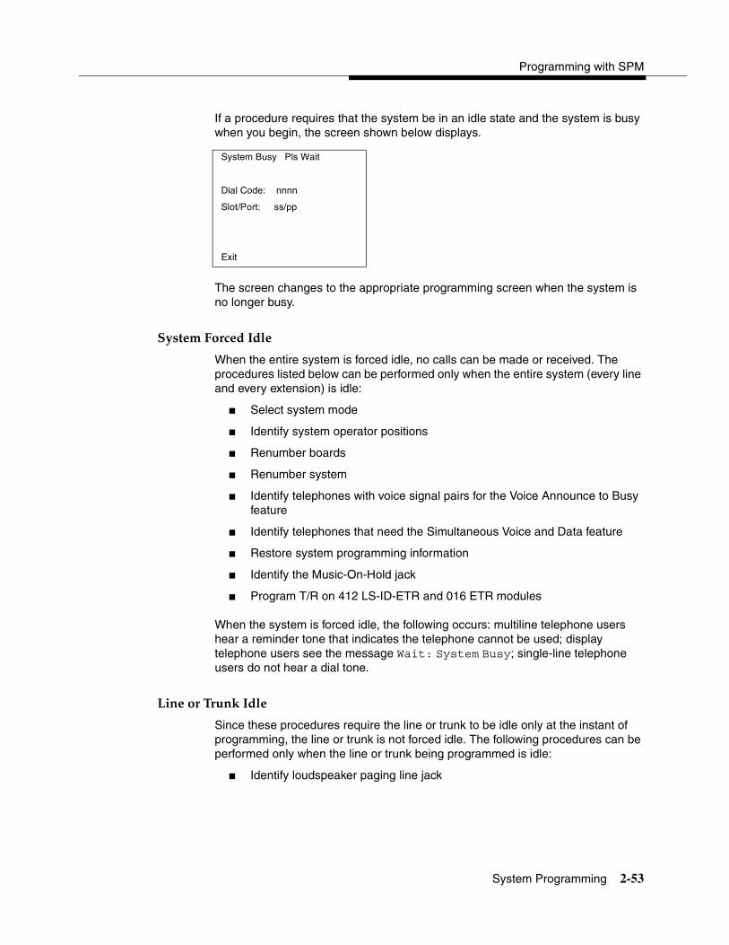
Programming with SPM
System Programming 2-53
If a procedure requires that the system be in an idle state and the system is busy when you begin, the screen shown below displays.
The screen changes to the appropriate programming screen when the system is no longer busy.
System Forced Idle 2
When the entire system is forced idle, no calls can be made or received. The procedures listed below can be performed only when the entire system (every line and every extension) is idle:
� Select system mode
� Identify system operator positions
� Renumber boards
� Renumber system
� Identify telephones with voice signal pairs for the Voice Announce to Busy feature
� Identify telephones that need the Simultaneous Voice and Data feature
� Restore system programming information
� Identify the Music-On-Hold jack
� Program T/R on 412 LS-ID-ETR and 016 ETR modules
When the system is forced idle, the following occurs: multiline telephone users hear a reminder tone that indicates the telephone cannot be used; display telephone users see the message Wait: System Busy; single-line telephone users do not hear a dial tone.
Line or Trunk Idle 2
Since these procedures require the line or trunk to be idle only at the instant of programming, the line or trunk is not forced idle. The following procedures can be performed only when the line or trunk being programmed is idle:
� Identify loudspeaker paging line jack
System Busy Pls Wait
Dial Code: nnnn
Slot/Port: ss/pp
Exit
System Programming
2-54 System Programming
� Assign trunks to pools
� Specify incoming or outgoing DID- or tie-trunk type
� Specify tie-trunk direction
� Specify tie-trunk E&M signal
Extension Forced Idle 2
When an extension is forced idle, no calls can be made or received on that extension. The following procedures can be performed only when the extension being programmed is idle:
� Assign call restrictions
� Assign pool dial-out restrictions
� Copy extension assignments
� Assign lines, trunks, or pools to extensions
� Assign labels to a personal directory
� Use centralized telephone programming
When the extension is forced idle, the following occurs: multiline telephone users hear a reminder tone that indicates the telephone cannot be used; display telephone users see the message Wait: System Busy; single-line telephone users do not hear a dial tone.
Forced Idle Reminder Tone 2
The forced idle reminder tone is a high-low “door-telephone” tone → 400 ms of 667 Hz tone followed by 400 ms of 571 Hz tone. The tone is provided under the following circumstances:
� At the extension, to remind the user that the system or the extension is in the forced idle state.
� At the programming console or at a PC running SPM, to remind the system manager that the system (or at least one extension) is in the forced idle state because of administrative activity.
In Release 1.1 and higher of the communications system, forced idle reminder tones occur every 20 seconds. You can adjust the volume of these tones with the volume control on the system console.
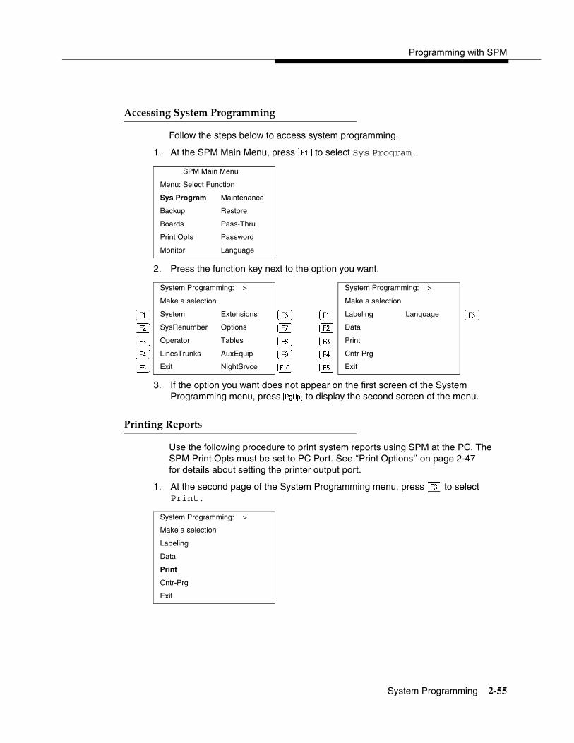
Programming with SPM
System Programming 2-55
Accessing System Programming 2
Follow the steps below to access system programming.
1. At the SPM Main Menu, press � to select Sys Program.
2. Press the function key next to the option you want.
3. If the option you want does not appear on the first screen of the System Programming menu, press � to display the second screen of the menu.
Printing Reports 2
Use the following procedure to print system reports using SPM at the PC. The SPM Print Opts must be set to PC Port. See ‘‘Print Options’’ on page 2-47 for details about setting the printer output port.
1. At the second page of the System Programming menu, press � to select Print.
SPM Main Menu
Menu: Select Function
Sys Program Maintenance
Backup Restore
Boards Pass-Thru
Print Opts Password
Monitor Language
System Programming: > System Programming: >
Make a selection Make a selection
� System Extensions � � Labeling Language � � SysRenumber Options � � Data
� Operator Tables � Print
LinesTrunks AuxEquip � Cntr-Prg
� Exit NightSrvce � � Exit
System Programming: >
Make a selection
Labeling
Data
Cntr-Prg
Exit

System Programming
2-56 System Programming
2. Press the function key that corresponds to the report to be printed.
3. Use one of the methods shown after this procedure to print the report or reports.
4. View the print status screen.
To interrupt printing and return to the SPM Main Menu, press �.
Print Hard Copy 2
To print a hardcopy of the report, use the arrow keys to highlight LPT1: and press �.
Print to Hard Disk 2
To print the reports to the hard disk if the print file does not exist, use the arrow keys to highlight MAKE NEW FILE and press �.
� To save to the default print filename (print.ams), press �.
� To save to the filename of your choice, type [filename] and press �.
To print the reports to the hard disk if the print file already exists, use the arrow keys to highlight the filename and press �.
Print (English): >
Make a selection
All Trunk Info
SysSet-up T1 Info
Dial Plan Pri Info
Labels RmoteAccess
Exit Oper Info
LPT1:
Please enter file name GOTO FLOPPY
to store print(default is print.ams)
MAKE NEW FILEPRINT.AMS
Press Esc to Abort.
Print in Progress ...
Exit
Programming with SPM
Upgrading the System 2-57
Print to Floppy Disk 2
Use the arrow keys to highlight GOTO FLOPPY: and press �. Use one of the methods shown below.
� To print the reports to a floppy disk if the print file does not exist, use the arrow keys to highlight MAKE NEW FILE and press �.
— To save to the default print filename (print.ams), press �.
— To save to the filename of your choice, type [filename] and press�.
� To print the reports to a floppy disk if the print file already exists, use the arrow keys to highlight the filename and press �.
Upgrading the System 2
! WARNING:The following procedures are to be used by qualified technicians or service personnel only. Installation or maintenance of this product by anyone other than qualified personnel may damage or impair the product; your limited warranty does not cover such damage. For details, see your limited warranty in ‘‘Customer Support Information’’ on page A-1.
Hazardous electrical voltages are present inside this product.
This section describes upgrading your communications system to Release 7.0. You can use this procedure to perform the following upgrades:
� Release 1.0 to Release 7.0
� Release 1.1 to Release 7.0
� Release 2.0 to Release 7.0
� Release 2.1 to Release 7.0
� Release 3.0 to Release 7.0
� Release 3.1 to Release 7.0
� Release 4.0 to Release 7.0
� Release 4.1 to Release 7.0
� Release 4.2 to Release 7.0
� Release 5.0 to Release 7.0
� Release 6.0 to Release 7.0
� Release 6.1 to Release 7.0

System Programming
2-58 Upgrading the System
NOTE:MERLIN II Communications System programming cannot be upgraded to this communications system. The new communications system must be completely reprogrammed.
Before You Begin 2
Before you begin the upgrade to Release 7.0, you will need the following items:
� Any version of DOS SPM or WinSPM to backup system programming information.
� WinSPM Release 2.0 or later which contains SPM Version 7.15 or later to convert and restore system programming information.
— If SPM is already installed, the Welcome to SPM screen that appears when you start SPM identifies the version on both the last line of the console simulation window and in the upper left corner of the screen. If you are working with Version 7.15, V7 appears in the upper left-hand corner of the screen and Version 7.15 appears on the last line of the console simulation window.
— The version of UNIX SPM packaged with Intuity does not support conversion. The most current version of DOS or UNIX SPM is available for download from the NSAC bulletin board.
� A CKE4 or later processor module (if one is not already installed in the system).
� An R7.0 Forced Installation PCMCIA Memory Card.
NOTES:� If a new processor module is installed as part of the upgrade procedure,
the system software is already installed. The R7.0 Forced Installation Memory Card is required only if you are upgrading a system and the processor module is not replaced.
� Releases 1.0/1.1 and 2.0/2.1 that are being upgraded to Release 7.0 require a new CKE4 processor board. Also, all earlier releases (1.0 to 6.1) with a CKE3 or earlier processor module must be upgraded to the new Release 7.0 CKE4 processor. The processor name appears on the label on the front of the module. If ‘CKE4’ does not appear on the label, the module must be upgraded.
� The 016 MLX module requires a CKE4 or later processor module. The processor name appears on the label on the front of the module. If ‘CKE4’ does not appear on the label, the module must be upgraded.

Programming with SPM
Upgrading the System 2-59
Upgrade Procedure 2
The system upgrade procedure must follow the order of the steps shown below.
1. Back up your system programming.
This step creates a file containing system programming information. See ‘‘Backup’’ on page 2-26. Any version of SPM may be used to back up system programming.
2. Install DOS SPM or WinSPM.
� If you are using DOS SPM, you must have Version 7.15 to upgrade the system to Release 7.0. If DOS SPM Version 7.15 is already installed on your system, proceed to Step 3. If it is not, see ‘‘Installing the SPM Software’’ on page 2-4.
� If you are using WinSPM, you must have Release 2.0 to upgrade the system to Release 7.0. If WinSPM Release 2.0 is already installed on your system, proceed to Step 3. If it is not, see the installation instructions that came with the software.
3. Convert your backup file.
This step converts the backup file created in Step 1. Refer to Table 2-4 to determine if the backup file needs to be converted to Release 7.0 format.
� If not required, continue with the next step.
� If required, convert the backup file. See ‘‘Convert’’ on page 2-35, then continue with the next step.
4. Turn off the AC power switches on the control unit in the following order:
a. Basic carrier.
b. Expansion carrier 1, if present.
c. Expansion carrier 2, if present.
5. If the system already has a processor module with a PCMCIA Memory Card slot installed, proceed to Step 6. Otherwise, continue with this step to replace the processor module:
� Unplug the interface cords from the SPM and SMDR printer ports on the processor module.
� Remove the processor module from Slot 0.
� Install the new processor module in Slot 0.
� Plug the interface cords into the SPM and SMDR printer ports on the processor module.

System Programming
2-60 Upgrading the System
6. If a new processor module was installed in Step 5, proceed to Step 7. Otherwise, insert the R7.0 forced installation memory card into the PCMCIA Memory Card slot on the processor module.
NOTE:Using the forced installation memory card will cause a frigid start.
7. Turn on the AC power switches on the control unit in the following order:
a. Expansion carrier 2, if present.
b. Expansion carrier 1, if present.
c. Basic carrier.
8. Restore your system programming.
The system is forced idle and cannot be used during this procedure. See ‘‘Restore’’ on page 2-48.
9. Program new features.
If you wish to use the factory settings for the new features available with Release 7.0, skip this step.
NOTE:When upgrading from a networked Release 6.0 (not a Release 6.1 system), the non-local dial plan extension ranges must be programmed to suit the customer’s configuration.
Tables 2-7 through 2-16 which follow present summary information for the programming required when upgrading to a later MERLIN LEGEND release.
Please note that you must perform all of the programming for all releases subsequent to the current release through the latest upgrade. For example, if you are upgrading from Release 1.0 to Release 3.1, you would consult Tables 2-6 through 2-9. Similarly, if upgrading from Release 5.0 to Release 7.0, you would consult Tables 2-14 through 2-16.
For programming needed after upgrade to… See…Release 1.1 Table 2-6Release 2.0/2.1 Table 2-7Release 3.0 Table 2-8Release 3.1 Table 2-9Release 4.0 Table 2-10Release 4.1 Table 2-11Release 4.2 Table 2-12Release 5.0 Table 2-13
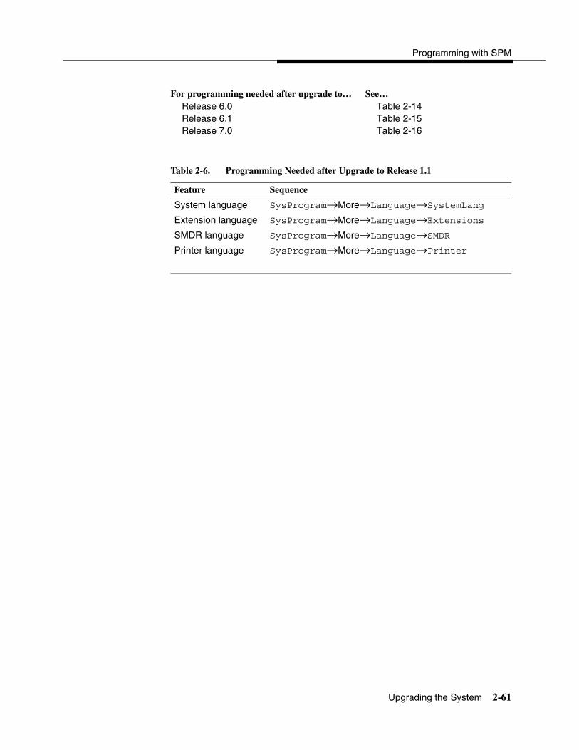
Programming with SPM
Upgrading the System 2-61
Release 6.0 Table 2-14Release 6.1 Table 2-15Release 7.0 Table 2-16
Table 2-6. Programming Needed after Upgrade to Release 1.1
Feature Sequence
System language SysProgram→More→Language→SystemLang
Extension language SysProgram→More→Language→Extensions
SMDR language SysProgram→More→Language→SMDR
Printer language SysProgram→More→Language→Printer
For programming needed after upgrade to… See…

System Programming
2-62 Upgrading the System
Table 2-7. Programming Needed after Upgrade to Release 2.0 or 2.1
Feature Sequence
Primary Rate SysProgram→LinesTrunks→LS/GS/DS1→Type→PRI
Interface (PRI) SysProgram→LinesTrunks→LS/GS/DS1→ FrameFormat
SysProgram→LinesTrunks→LS/GS/DS1→Suppression
SysProgram→LinesTrunks→PRI→PhoneNumber
SysProgram→LinesTrunks→PRI→B-ChannlGrp
SysProgram→LinesTrunks→PRI→NumbrToSend
SysProgram→LinesTrunks→PRI→Test TelNum
SysProgram→LinesTrunks→PRI→Protocol
SysProgram→LinesTrunks→PRI→DialPlanRtg
SysProgram→LinesTrunks→PRI→OutgoingTbl
SysProgram→Tables→ARS
DID Emulation on T1
SysProgram→LinesTrunks→LS/GS/DS1→Type→ More→DID/All DID
Night Service Calling Group
SysProgram→NightSrvce→GroupAssign→Calling Group
Coverage VMS Off SysProgram→More→Cntr-Prg→Program Ext
Data Status SysProgram→More→Cntr-Prg→Program Ext
Extension Copy SysProgram→More→Cntr-Prg→Copy Ext
Posted Message button on MLX-10 nondisplay and analog multiline telephones (for use with Do Not Disturb)
SysProgram→More→Cntr-Prg→Program Ext

Programming with SPM
Upgrading the System 2-63
Table 2-8. Programming Needed after Upgrade to Release 3.0
Feature Sequence
Automatic Backup SysProgram→System→Back/Restore→Auto Backup
Incoming Call Line Identification Delay
LinesTrunks→More→LS-ID Delay→Drop→ Dial trunk no.→Enter
Remote Access Barrier Codes
LinesTrunks→RemoteAccss→BarrierCode→ Code Info→Code Length
LinesTrunks→RemoteAccss→BarrierCode→ Code Info→Code Entry
Authorization Codes
Extensions→More→Auth Code
Table 2-9. Programming Needed after Upgrade to Release 3.1
Feature Sequence
Trunk-to-Trunk Transfer
Extensions→More→More→TrkTransfer→Toggle LED on/off or Dial ext. no.→Enter→Exit→Exit
Second Dial Tone Timer
Options→More→SecDT→Dial second dial tone timer value→Enter

System Programming
2-64 Upgrading the System
Table 2-10. Programming Needed after Upgrade to Release 4.0
Feature Sequence
Delayed Call Forwarding
Extensions→More→Delay Frwd→Dial ext. no.→ Enter→Dial no. of delay rings→Enter
Group Calling Overflow and Thresholds
Extensions→More→Grp Calling→Overflow→ Dial calling group ext. no.→Enter→Dial ext. no.→Enter→Number Based Overflow→Drop→Dial no. of calls→Enter→Time Based Overflow→Drop→Dial no. of seconds→Enter
Voice Announce on a QCC
Operator→Queued Call→More→Voice Annc→ Enabled or Disabled→Enter
2B Data Data→2B Data→Dial adjunct ext. no.→Enter
Basic Rate Interface (BRI)
LinesTrunks→More→BRI→SPID/DN.→Dial line/trunk no.→Enter→Drop→Dial SPID→Enter→Drop→ Dial DN→Enter
LinesTrunks→More→BRI→Timers→Select timer→ Drop→Dial no. of seconds or ms→Enter
Clock Synchronization
LinesTrunks→More→ClockSync→Primary→Drop→Dial slot no.→Enter→Dial port no. or select source of synchronization→Enter→Secondary→Dial slot no.→Enter→Dial port no. or select synchronization source→Enter→Tertiary→Dial slot no.→Enter→ Dial port no. or select source of synchronization→Enter
Ringing Frequency(016 T/R module)
Options→More→Ringing Freq→Dial slot no.→ Select 20Hz or 25Hz→Enter

Programming with SPM
Upgrading the System 2-65
Table 2-11. Programming Needed after Upgrade to Release 4.1
Feature Sequence
Group Coverage Ring Delay
SysProgram→Extensions→More→More→ Cover Delay→Group Cover→sender’s extension→ number of rings→Enter
Primary Cover Ring Delay
SysProgram→Extensions→More→More→ Cover Delay→Primary→sender’s extension→number of rings→Enter
Secondary Cover Ring Delay
SysProgram→Extensions→More→More→ Cover Delay→Secondry→sender’s extension→number of rings→Enter
Night Service Group Line Assignment
SysProgram→NightSrvce→GroupAssign→Lines→ Night Service attendant position number→Enter→ line number→Enter
Night Service Coverage Control
SysProgram→NightSrvce→CoverContrl→Enable or Disable→Enter
Board Renumber[when an 012 (T/R) module is replaced by an 016 (T/R) module]
System→Board Renum→Yes

System Programming
2-66 Upgrading the System
Feature Sequence
Switched 56 Data To select T1 All Tie: Switched 56 Data:LinesTrunks→LS/GS/DS1→Dial slot no.→ Enter→Type→T1→Enter→All TIE→Enter→S56→ Enter→Dial channel no.→Enter→Exit→Exit→Exit→Exit
To select T1 Tie: Switched 56 Data:LinesTrunks→LS/GS/DS1→Dial slot no.→ Enter→Type→T1→Enter→TIE→Enter→S56→Enter→Dial channel no.→Enter→Exit→Exit→Exit→Exit
To select T1 All: Switched 56 Data:LinesTrunks→LS/GS/DS1→Dial slot no.→Enter→ Type→T1→Enter→More→ALL S56 Data→ Enter→Select Direction, Intype, Outtype, AnsSupv, Disconnect, Inmode, or Outmode→Program options→Enter→Exit→Exit→Exit→Exit
To select T1: Switched 56 Data:LinesTrunks→LS/GS/DS1→Dial slot no.→Enter→ Type→T1→Enter→More→S56 Data→Enter→Dial channel no.→Enter→Select Direction, Intype, Outtype, AnsSupv, Disconnect, Inmode, or Outmode→ Program options→Enter→Exit→Exit→Exit→Exit
Switched 56 DataNetwork Dial Plan Routing
To specify Expected Digits:LinesTrunks→More→T1 Data NW→S56 Dial Plan Routing→Expected Digits→Drop→Dial expected digits→Enter→Exit→Exit→Exit
To specify Delete Digits:LinesTrunks→More→T1 Data NW→S56 Dial Plan Routing→Delete Digits→Drop→Dial delete digits→Enter→Exit→Exit→Exit
To specify Add Digits:LinesTrunks→More→T1 Data NW→S56 Dial Plan Routing→Add Digits→Drop→Dial add digits→ Enter→Exit→Exit→Exit
Table 2-11. Programming Needed after Upgrade to Release 4.1—Continued
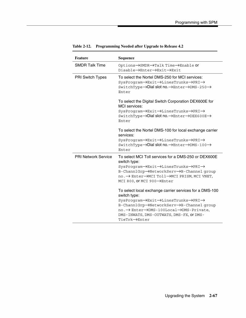
Programming with SPM
Upgrading the System 2-67
Table 2-12. Programming Needed after Upgrade to Release 4.2
Feature Sequence
SMDR Talk Time Options→SMDR→Talk Time→Enable or Disable→Enter→Exit→Exit
PRI Switch Types To select the Nortel DMS-250 for MCI services:SysProgram→Exit→LinesTrunks→PRI→SwitchType→Dial slot no.→Enter→DMS-250→Enter
To select the Digital Switch Corporation DEX600E for MCI services:SysProgram→Exit→LinesTrunks→PRI→ SwitchType→Dial slot no.→Enter→DEX600E→Enter
To select the Nortel DMS-100 for local exchange carrier services:SysProgram→Exit→LinesTrunks→PRI→SwitchType→Dial slot no.→Enter→DMS-100→ Enter
PRI Network Service To select MCI Toll services for a DMS-250 or DEX600E switch type:SysProgram→Exit→LinesTrunks→PRI→B-ChannlGrp→NetworkServ→B-Channel group no.→ Enter→MCI Toll→MCI PRISM, MCI VNET, MCI 800, or MCI 900→Enter
To select local exchange carrier services for a DMS-100 switch type:SysProgram→Exit→LinesTrunks→PRI→B-ChannlGrp→NetworkServ→B-Channel group no.→ Enter→DMS-100Local→DMS-Private, DMS-INWATS, DMS-OUTWATS, DMS-FX, or DMS-TieTrk→Enter

System Programming
2-68 Upgrading the System
Feature Sequence
PRI Dial Plan Routing To specify MCI Toll Dial Plan Routing services for a DMS-250 or DEX600E switch type:SysProgram→Exit→LinesTrunks→PRI→DialPlanRtg→Service→Entry no.→Enter→MCI Toll→MCI PRISM, MCI VNET, MCI 800, orMCI 900→Enter
To specify local exchange carrier Dial Plan Routing services for a DMS-100 switch type:SysProgram→Exit→LinesTrunks→PRI→DialPlanRtg→Service→Entry no.→Enter→DMS-100Local→DMS-Private, DMS-INWATS, DMS-OUTWATS, DMS-FX, or DMS-TieTrk→Enter
PRI Call-by-Call Services Table
To select MCI Toll Call-by-Call Services for a DMS-250 or DEX600E switch type:SysProgram→Exit→LinesTrunks→PRI→OutgoingTbl→CBC Service→NetworkServ→ List no.→Enter→MCI Toll→MCI PRISM or MCI VNET→Enter
To specify local exchange carrier Dial Plan Routing services for a DMS-100 switch type:SysProgram→Exit→LinesTrunks→PRI→OutgoingTbl→CBC Service→NetworkServ→ List no.→Enter→DMS-100Local→DMS-Private, DMS-OUTWATS, DMS-FX, or DMS-TieTrk→Enter
Table 2-12. Programming Needed after Upgrade to Release 4.2—Continued
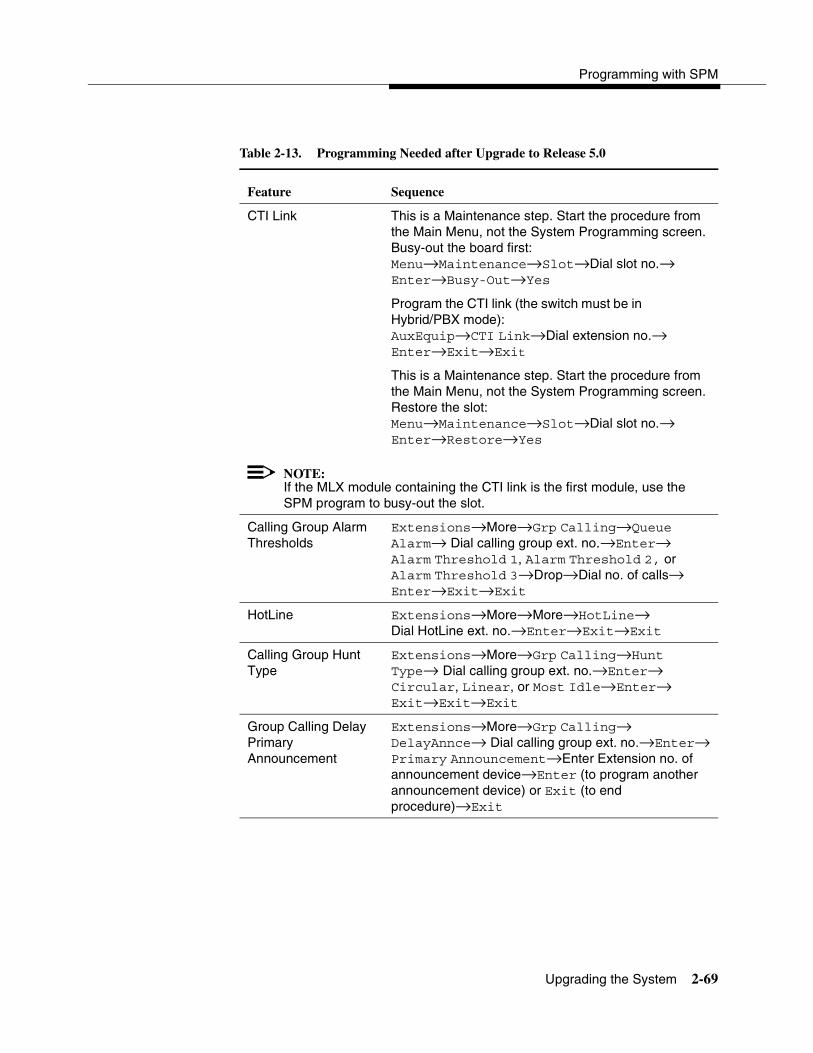
Programming with SPM
Upgrading the System 2-69
Table 2-13. Programming Needed after Upgrade to Release 5.0
Feature Sequence
CTI Link This is a Maintenance step. Start the procedure from the Main Menu, not the System Programming screen. Busy-out the board first:Menu→Maintenance→Slot→Dial slot no.→ Enter→Busy-Out→Yes
Program the CTI link (the switch must be in Hybrid/PBX mode):AuxEquip→CTI Link→Dial extension no.→Enter→Exit→Exit
This is a Maintenance step. Start the procedure from the Main Menu, not the System Programming screen. Restore the slot:Menu→Maintenance→Slot→Dial slot no.→ Enter→Restore→Yes
NOTE:If the MLX module containing the CTI link is the first module, use the SPM program to busy-out the slot.
Calling Group Alarm Thresholds
Extensions→More→Grp Calling→Queue Alarm→ Dial calling group ext. no.→Enter→Alarm Threshold 1, Alarm Threshold 2, or Alarm Threshold 3→Drop→Dial no. of calls→Enter→Exit→Exit
HotLine Extensions→More→More→HotLine→ Dial HotLine ext. no.→Enter→Exit→Exit
Calling Group Hunt Type
Extensions→More→Grp Calling→Hunt Type→ Dial calling group ext. no.→Enter→Circular, Linear, or Most Idle→Enter→Exit→Exit→Exit
Group Calling Delay Primary Announcement
Extensions→More→Grp Calling→ DelayAnnce→ Dial calling group ext. no.→Enter→Primary Announcement→Enter Extension no. of announcement device→Enter (to program another announcement device) or Exit (to end procedure)→Exit
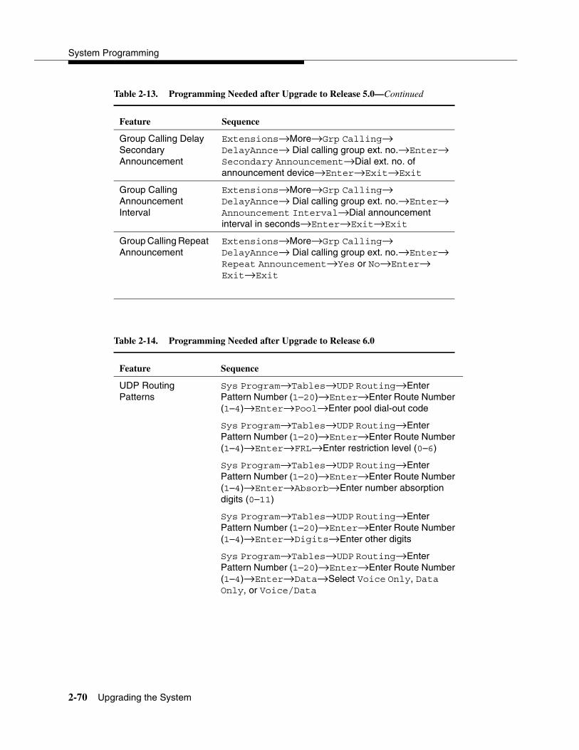
System Programming
2-70 Upgrading the System
Feature Sequence
Group Calling Delay Secondary Announcement
Extensions→More→Grp Calling→ DelayAnnce→ Dial calling group ext. no.→Enter→Secondary Announcement→Dial ext. no. of announcement device→Enter→Exit→Exit
Group Calling Announcement Interval
Extensions→More→Grp Calling→ DelayAnnce→ Dial calling group ext. no.→Enter→Announcement Interval→Dial announcement interval in seconds→Enter→Exit→Exit
Group Calling Repeat Announcement
Extensions→More→Grp Calling→ DelayAnnce→ Dial calling group ext. no.→Enter→Repeat Announcement→Yes or No→Enter→Exit→Exit
Table 2-14. Programming Needed after Upgrade to Release 6.0
Feature Sequence
UDP Routing Patterns
Sys Program→Tables→UDP Routing→Enter Pattern Number (1–20)→Enter→Enter Route Number (1–4)→Enter→Pool→Enter pool dial-out code
Sys Program→Tables→UDP Routing→Enter Pattern Number (1–20)→Enter→Enter Route Number (1–4)→Enter→FRL→Enter restriction level (0–6)
Sys Program→Tables→UDP Routing→Enter Pattern Number (1–20)→Enter→Enter Route Number (1–4)→Enter→Absorb→Enter number absorption digits (0–11)
Sys Program→Tables→UDP Routing→Enter Pattern Number (1–20)→Enter→Enter Route Number (1–4)→Enter→Digits→Enter other digits
Sys Program→Tables→UDP Routing→Enter Pattern Number (1–20)→Enter→Enter Route Number (1–4)→Enter→Data→Select Voice Only, Data Only, or Voice/Data
Table 2-13. Programming Needed after Upgrade to Release 5.0—Continued

Programming with SPM
Upgrading the System 2-71
Feature Sequence
Sys Program→Extensions→More→More→ DisplayPre→Dial ext. no.→Enter→Select Calling Name, Calling Num, or Both
Sys Program→SysRenumber→NonLocal UDP→ Enter starting number→Enter→Enter ending number
Sys Program→LinesTrunks→More→UDP→ SwNum-Single→Enter trunk number→Enter→ Enter switch number→Enter
Sys Program→LinesTrunks→More→UDP→SwNum-Block→Enter starting number→Enter→ Enter ending trunk→Enter→Enter switch number→Enter
Sys Program→LinesTrunks→More→UDP→ SMDR→Enter trunk number→Enter→Select Logincoming, Log outgoing, Log both, or Log none
Sys Program→LinesTrunks→PRI→B-ChannlGrp→ NetworkServ→Enter→LegendUDP→Select ElecTandNtwk
Sys Program→LinesTrunks→PRI→B-ChannlGrp→IncomingRtg→Enter→Route Directly to UDP→Enter
Sys Program→LinesTrunks→PRI→SwitchType (Select Legend-Ntwk or Legend-PBX)→Enter
Table 2-14. Programming Needed after Upgrade to Release 6.0—Continued

System Programming
2-72 Upgrading the System
Table 2-15. Programming Needed after Upgrade to Release 6.1
Feature Sequence
Service Observing
To assign a Service Observer to a Service Observing group:Extensions→More→More→ServiceObs→Observer→Dial group no.→Enter→Dial ext. no. of Service Observer→Enter or Delete→Exit→Exit
To enable or disable Warning Tone on a per group basis:Extensions→More→More→ServiceObs→Warning→Dial group no.→Enter→Yes or No→Enter→Exit→Exit
To assign a member extension to a Service Observing group:Extensions→More→More→ServiceObs→Members→Dial group no.→Enter→Dial ext. no.→Enter or Delete→Exit→Exit→Exit
SMDR Log UDP Calls
Options→SMDR→UDP→Log Incoming/Outgoing or Log None→Exit
Non-Local Dial Plan Extension Ranges
SysRenumber→NonLocal UDP→Dial no. of first extension in range→Enter→Dial no. of last ext in range→ Enter→ Dial max. no. of digits user can enter to reach an ext in range→Enter→Dial pattern no. for ext range→ Enter→ Exit→Exit

Programming with SPM
Surrogate Mode Programming 2-73
Surrogate Mode Programming 2
Surrogate mode allows qualified service personnel to perform system programming at an offsite service location. The actual communications system hardware does not have to be installed — the programmer needs a power supply, carrier, processor, and a direct connection from the PC to the processor module. By following a customer’s set of completed planning forms, the system can be programmed as if the appropriate modules, trunks, telephones, and other communications equipment have been installed. When system programming is completed, a system backup is performed to save the information on disk. This backup disk is then taken to the new installation site and used with the Restore option to provide complete system programming for a new communications system.
Table 2-16. Optional Programming after Upgrade to Release 7.0
Feature Sequence
Voice Announce Receive
Extensions→Dial ext. no.→Enter→SysProg→Start→Choose a button→ListFeatMore→More→More→More→VoiceAnnounce
Caller Number and Name on Caller ID
LinesTrunks→More→LS-ID Delay→EntryMode→ Type trunk no.→Enter
Priority Call Queuing
Extensions→More→Grp Calling→More→ Priority→Enter extension number of group→ Enter→Enter Group Priority (1–32)→(To program the next group, select Next)→Enter→Exit→ Support→ Enter extension number of group→ Enter→Enter Support Group→(To program the next group, select Next)→Enter→Exit→Exit→Exit
Tip/Ring Functionality on 412 LS-ID-ETR and 016 ETR Modules
Extensions→More→More→ETR→Type ext. no.→ Enter→Type ETR tip/ring port→Select port type→Enter→Exit→Exit
Rotary Signaling on Tip/Ring Ports
Extensions→More→More→RotaryEnabl→Type rotary ext. no.→Enter→Exit→Exit
System Programming
2-74 Surrogate Mode Programming
You do not “select” surrogate mode programming—you enter it automatically under the following conditions:
� The PC is connected to the lower RS-232 port on a control unit (direct local connection).
� Only the processor and power modules are connected.
Once you enter surrogate mode programming, you must follow the sequence of procedures shown below.
� At the service location, perform the following:
1. System Erase
2. Program the Boards
3. System Programming
4. Backup
� At the installation site, perform a Restore.
While you are in surrogate mode, the Pass-Thru and Password options are not available.
NOTE:Surrogate mode is available only through the local programming port. You cannot access surrogate features through the system programming console.

��������
3-i
3�������� ����������
�������� 3-1
���� ������ ������� ���������� 3-2
������ ���������� 3-10
������ ������� ��������� 3-21
����� �� ������ 3-25
������� �� � � !�� ����� 3-42
��" !�� ����� 3-45
��� ������ 3-54
�#� ������ 3-61
��# !�� ����� 3-67
��# !�� ����� 3-88
$%�������� 3-92
&�%� ��� $'������� 3-106
�������� �� ��(��� #�������� )��#* ���� 3-112
������ $%������� !������ 3-118
������ ������� !������ 3-135
+�� ������ !������ 3-137
������ ,���� !������ 3-148
������ ,���� � �� !������ 3-155
������ !������ 3-167

3-ii
��������
System Programming
������ &����� !������ 3-186
&������� ����� �� ������ 3-197
������� �� � � ������ 3-208
-�(� ������� 3-214
��� �� 3-219
����� ������� 3-224
�� !������ 3-228
.����� ��� 3-231

Overview 3-1
3Programming Procedures 3
Overview 3
This chapter contains all of the procedures required for programming each of the features and options that is available for the MERLIN LEGEND Communications System.
Each of the procedures begins at the System Programming menu. Use one of the methods shown below to display the System Programming menu.
� At the console: Menu→Sys Program→Exit
� At the PC or with SPM: Type spm→�→Press any key→�→�
Before you begin any of the procedures in this chapter, you should read and understand all of the information presented in Chapter 1, ‘‘Programming Basics.”

System Programming
3-2 Basic System Operating Conditions
Basic System Operating Conditions 3
The procedures in this section are all related to the system, rather than to the operation of telephones, operator positions, lines, or trunks. These are operating conditions that must be set only once—when the system is new or when you reset the factory settings.
NOTE:You must reset the system time when Daylight Savings Time begins and ends.
This section contains the following programming procedures:
� System Restart
� System Programming Position Assignment
� System Language
� Board Renumbering
� Mode of Operation
� Automatic Maintenance Busy
� System Date
� System Time
System Restart 3
! CAUTION:This procedure is to be performed by qualified support personnel only.
Use this procedure to perform a System Restart (cold start). All calls are dropped when you perform this procedure. Existing system programming is saved. Telephones with the Extension Status feature may lose toll restrictions as a result of a System Restart.
Summary: System Restart 3
Programmable by Qualified support personnel
Mode All
Idle Condition Not required
Planning Form Not applicable
Factory Setting None

Programming Procedures
Basic System Operating Conditions 3-3
Valid Entries None
Inspect No
Copy Option No
Console Procedure System→Restart→Yes
PC Procedure �→�→�
System Programming Position Assignment 3
Use this procedure to reassign the extension used for system programming. This extension should not be the same extension as that used for the operator position. The system programming position can be reassigned only to one of the first five extension jacks on the first MLX module. Only one system programming console is allowed per system.
If you are programming on the console, be aware of the following:
� The console must be connected to the extension currently assigned for system programming.
� As soon as you change the system programming extension, the system programming session is terminated. To proceed with system programming, you must connect the system programming console to the newly assigned extension and enter system programming again.
NOTE:The telephone used for system programming must be an MLX-20L.
Summary: System Programming Position Assignment 3
Programmable by System Manager
Mode All
Idle Condition Not required
Planning Form 1, System Planning
Factory Setting First extension jack on the first MLX module (also set as an operator position)
Valid Entries Extension number of one of the first five extension jacks on the first MLX module
Inspect No
Copy Option No

System Programming
3-4 Basic System Operating Conditions
Console Procedure System→SProg Port→Drop→Dial ext. no.→ Enter→Exit
PC Procedure �→�→� + �→Type ext. no.→�→�
System Language 3
Your communications system offers you a choice of three languages (English, French, and Spanish) for the following options:
� System Language. For system programming.
� Station Message Detail Recording (SMDR) Reports. See ‘‘SMDR Language’’ on page 3-174.
� Print Reports. See ‘‘Report Language’’ on page 3-224.
� Extensions. See ‘‘Optional Extension Features’’ on page 3-118.
Use this procedure to set the system language. See the sections listed above to set a different language for SMDR reports and print reports, as well as for an MLX display telephone.
NOTE:MERLIN LEGEND Communications System Release 1.0 does not offer a choice of languages.
Summary: System Language 3
Programmable by System Manager
Mode All
Idle Condition Not required
Planning Form 1, System Planning
Factory Setting English
Valid Entries English, French, Spanish
Inspect No
Copy Option No
Console Procedure More→Language→SystemLang→Yes→Select a language (English, French, or Spanish)→Enter
PC Procedure �→�→�→→Select a language (English, French, or Spanish)→�

Programming Procedures
Basic System Operating Conditions 3-5
Board Renumbering 3
! CAUTION:This procedure is to be performed by qualified support personnel only.
Use this procedure to renumber boards that have already been installed. This procedure restarts the system (system programming is not lost). Note that this is not the same procedure used with the Boards option, which is available to qualified service personnel with SPM only.
Board Renumbering is a system programming procedure that is required only when an existing module is replaced by a different type of module. When a Board Renumbering is performed, the system reassigns the logical ID numbers to the extension and line ports sequentially from left to right in the control unit and from bottom to top of each module.
Summary: Board Renumbering 3
Programmable by Qualified support personnel only
Mode All
Idle Condition System idle
Planning Form Not applicable
Factory Setting None
Valid Entries Not applicable
Inspect Not applicable
Copy Option Not applicable
Console Procedure System→Board Renum→Yes
PC Procedure �→→�
Mode of Operation 3
The system mode—Key, Behind Switch, or Hybrid/PBX—determines how the system operates and directly affects the following operations:
� How lines and/or trunks are provided to users
� Types of operator consoles allowed
� Features available
Changing this option causes a system restart and terminates the programming session. You must enter system programming again to program other features.

System Programming
3-6 Basic System Operating Conditions
NOTE:The Hybrid/PBX option is not available if the control unit processor module has been modified to operate in Permanent Key mode only. See the Feature Reference for more information.
The following options cannot be programmed for Behind Switch or Key systems:
� Automatic Route Selection (ARS)
� Pools
� Queued Call Consoles (QCCs) and associated features
� Direct Inward Dialing (DID) Trunks
� System Access buttons
� Dial Plan Routing (PRI)
� Call-by-Call Services (PRI)
The Ground-Start lines/trunks option cannot be programmed if the processor module has been modified for Permanent Key mode operation only.
Summary: Mode of Operation 3
Programmable by System Manager
Mode All
Idle Condition System idle
Planning Form 1, System Planning
Factory Setting Hybrid/PBX
Valid Entries Key, Behind Switch, Hybrid/PBX
Inspect No
Copy Option No
Console Procedure System→Mode→Select mode (Key, Behind Switch, or Hybrid/PBX)→Enter
PC Procedure �→→Select mode (Key, Behind Switch, or Hybrid/PBX)→�
Automatic Maintenance Busy 3
Automatic Maintenance Busy allows the system to take a malfunctioning trunk out of service for outgoing calls (incoming calls are never blocked). This prevents faulty outside facilities from causing disruptions in outgoing calling patterns.
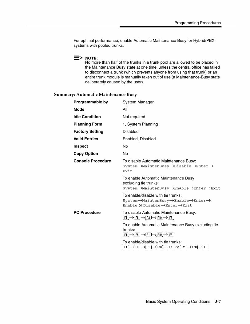
Programming Procedures
Basic System Operating Conditions 3-7
For optimal performance, enable Automatic Maintenance Busy for Hybrid/PBX systems with pooled trunks.
NOTE:No more than half of the trunks in a trunk pool are allowed to be placed in the Maintenance Busy state at one time, unless the central office has failed to disconnect a trunk (which prevents anyone from using that trunk) or an entire trunk module is manually taken out of use (a Maintenance-Busy state deliberately caused by the user).
Summary: Automatic Maintenance Busy 3
Programmable by System Manager
Mode All
Idle Condition Not required
Planning Form 1, System Planning
Factory Setting Disabled
Valid Entries Enabled, Disabled
Inspect No
Copy Option No
Console Procedure To disable Automatic Maintenance Busy:System→MaintenBusy→Disable→Enter→Exit
To enable Automatic Maintenance Busy excluding tie trunks: System→MaintenBusy→Enable→Enter→Exit
To enable/disable with tie trunks:System→MaintenBusy→Enable→Enter→Enable or Disable→Enter→Exit
PC Procedure To disable Automatic Maintenance Busy:�→�→�→�→�
To enable Automatic Maintenance Busy excluding tie trunks:�→�→�→�→�
To enable/disable with tie trunks:�→�→�→�→� or �→�→�
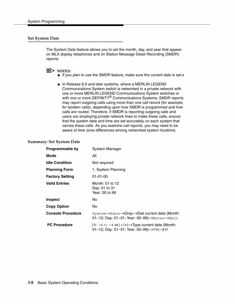
System Programming
3-8 Basic System Operating Conditions
Set System Date 3
The System Date feature allows you to set the month, day, and year that appear on MLX display telephones and on Station Message Detail Recording (SMDR) reports.
NOTES:� If you plan to use the SMDR feature, make sure the current date is set.s
� In Release 6.0 and later systems, where a MERLIN LEGEND Communications System switch is networked in a private network with one or more MERLIN LEGEND Communications System switches or with one or more DEFINITY® Communications Systems, SMDR reports may report outgoing calls using more than one call record (for example, for tandem calls), depending upon how SMDR is programmed and how calls are routed. Therefore, if SMDR is reporting outgoing calls and users are employing private network lines to make these calls, ensure that the system date and time are set accurately on each system that carries these calls. As you examine call reports, you may need to be aware of time zone differences among networked system locations.
Summary: Set System Date 3
Programmable by System Manager
Mode All
Idle Condition Not required
Planning Form 1, System Planning
Factory Setting 01-01-00
Valid Entries Month: 01 to 12Day: 01 to 31Year: 00 to 99
Inspect No
Copy Option No
Console Procedure System→Date→Drop→Dial current date (Month: 01–12; Day: 01–31; Year: 00–99)→Enter→Exit
PC Procedure �→�→� +�→Type current date (Month: 01–12; Day: 01–31; Year: 00–99)→�→�

Programming Procedures
Basic System Operating Conditions 3-9
Set System Time 3
NOTES:� The System Time feature allows you to set the time that appears on
MLX, ETR, and MLS display telephones and on SMDR reports.
� If you are planning to use the SMDR feature, make sure the system time is set accurately. If you change the system time while the system is in Night Service mode, Night Service is deactivated and must be manually reactivated. If you have installed applications such as MERLIN LEGEND Mail or Intuity AUDIX, you may need to set the time in the applications software whenever you reset the system time.
� In Release 6.0 and later systems, where a MERLIN LEGEND Communications System is networked in a private network with one or more MERLIN LEGEND Communications Systems or with one or more DEFINITY Communications Systems, SMDR reports may report outgoing calls using more than one call record (especially for tandem calls), depending upon how SMDR is programmed and how calls are routed. Therefore, ensure that the system date and time are set accurately on each system that carries these calls. When you examine records for network calls, you may need to be aware of time zone differences among different system locations.
Summary: Set System Time 3
Programmable by System Manager
Mode All
Idle Condition Not Required
Planning Form 1, System Planning
Factory Setting 0000
Valid Entries 0000 to 2359
Inspect No
Copy Option No
Console Procedure System→Time→Drop→Dial current time (0000–2359)→Enter→Exit
PC Procedure �→�→� +�→Type current time (0000–2359)→�→�
System Programming
3-10 System Renumbering
System Renumbering 3
The procedures in this section are used to assign the 2-digit, 3-digit, and Set-Up-Space numbering plans for the local MERLIN LEGEND Communications System.
NOTE:System Renumbering is called Flexible Numbering in the MERLIN II Communications System. This is not the same as Board Renumbering, an option used when modules in the control unit are changed.
Do not attempt to assign a numbering plan without Planning Forms 2a, System Numbering: Extension Jacks; 2b, System Numbering: Digital Adjuncts; and 2d, System Numbering: Special Renumbers. Form 6a, Optional Operator Features, is needed to assign a DSS Page button. This section contains the following programming procedures:
� Select System Numbering Plan
� Single Renumbering
� Block Renumbering
� Non-Local Dial Plan Renumbering (Release 6.0 and later systems only)
� Direct Station Selector (DSS) Page Button Assignment
For the local system, you then select only one of the numbering plans (2-digit numbering, 3-digit numbering, or Set-Up-Space numbering). In addition, you may need to perform single and/or block renumbering. You do not need to assign DSS Page buttons unless the system programming console or one of the operator positions is connected to a DSS. No matter which procedures you need to perform, assign the numbering plan first, then do single and/or block renumbering, and finally, assign DSS Page buttons (if necessary).
In Release 6.0 and later systems (Hybrid/PBX mode only), you may choose non-local dial plan numbering to specify the numbering of extensions connected to remote private network systems and to allow users on your system to access those extensions as if they were connected to your own system. You specify only ranges of extensions.
NOTE:Refer to the Network Reference for information on private networking and non-local dial plan numbering.
Use the single renumbering procedure whenever the extension numbers you are changing from or to are not sequential.

Programming Procedures
System Renumbering 3-11
Block renumbering is quicker, but you can use block renumbering only when the extension numbers you are changing from and to are sequential.
When trunk or extension modules are removed from the control unit, the remaining modules must be rearranged so that no empty slots remain. The system does not acknowledge any modules installed after an empty slot; therefore, if the system is renumbered, extensions are not assigned to extension jacks after the empty slots.
NOTE:Figure 3-1, Figure 3-2, and Figure 3-3 show the factory settings in the gray spaces. Extensions can be renumbered to any number shown in the white spaces.
Figure 3-1. 2-Digit Numbering
0 Operator Console (not flexible) 01 Extensions 10−192 Extensions 20−293 Extensions 30−394 Extensions 40−495 Extensions 50−596 Extensions 60 −−66 Extra
Extensions6700−6842
6843−6849
Extra MFMs/Terminal Adapters6850−6992
6993−6999
7 Main Pool70
MFMs/Terminal Adapters710−766
767−769
Calling Groups770–791,7920−7929
PagingGroups793−799
8 8001 Trunks 801−880 Park881−888
8892 Pools 890 −−899
9 ARS Access (Hybrid/PBX Mode) / Idle Line Access 9
1 Listed Directory Number (QCC Queue)2 Remote AccessNOTE: “0” and “10” are the same station.
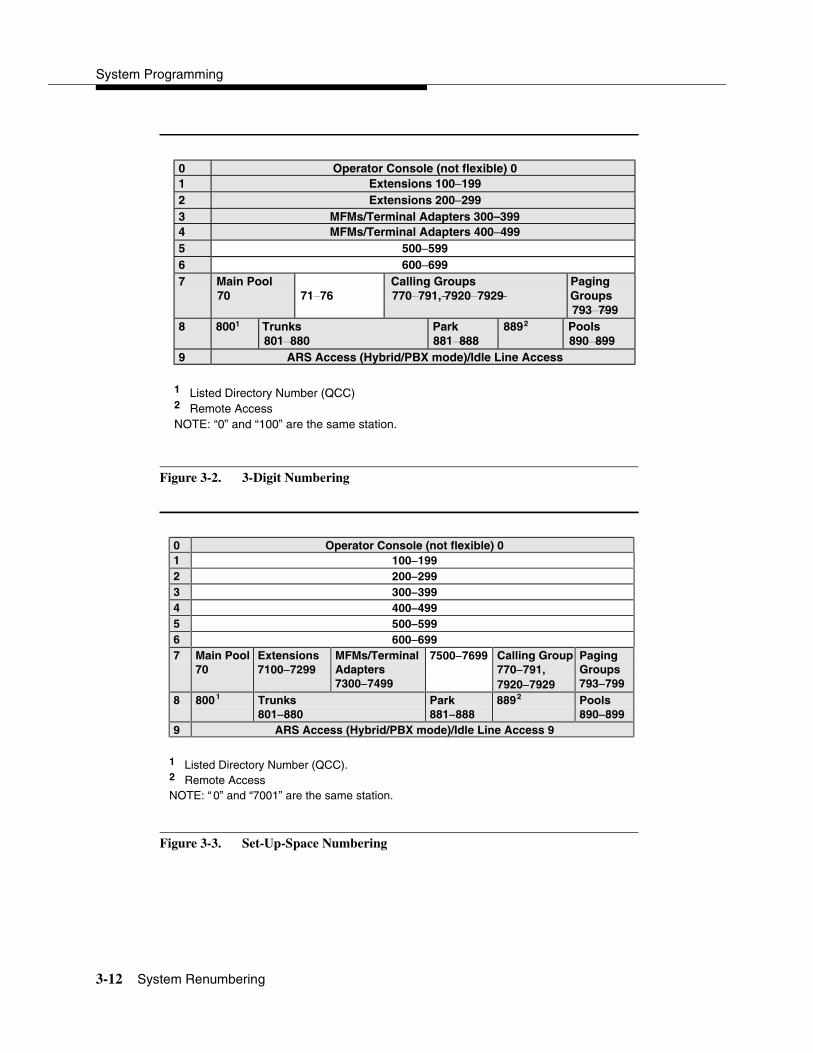
System Programming
3-12 System Renumbering
Figure 3-2. 3-Digit Numbering
Figure 3-3. Set-Up-Space Numbering
0 Operator Console (not flexible) 01 Extensions 100−1992 Extensions 200−2993 MFMs/Terminal Adapters 300–3994 MFMs/Terminal Adapters 400−4995 500−5996 600−6997 Main Pool
70 71−76Calling Groups770 −−791, 7920 −−7929
PagingGroups793 −−799
8 8001 Trunks801−880
Park881 −−888
8892 Pools890 −−899
9 ARS Access (Hybrid/PBX mode)/Idle Line Access
1 Listed Directory Number (QCC)2 Remote AccessNOTE: “0” and “100” are the same station.
0 Operator Console (not flexible) 01 100−−1992 200−−2993 300−−3994 400−−4995 500−−5996 600−−6997 Main Pool
70Extensions7100−−7299
MFMs/TerminalAdapters7300−−7499
7500−−7699 Calling Group770−−791,7920−−7929
PagingGroups793−−799
8 8001 Trunks801−−880
Park881−−888
8892 Pools890−−899
9 ARS Access (Hybrid/PBX mode)/Idle Line Access 9
1 Listed Directory Number (QCC).2 Remote AccessNOTE: “ 0” and “7001” are the same station.
Programming Procedures
System Renumbering 3-13
Select System Numbering Plan 3
! WARNING:To avoid possible loss of system programming information, renumber the system before you program the rest of the options described in this chapter.
The three available local system numbering plans listed below appear on System Planning Form 2a.
� Two-Digit. This plan is for systems with fewer than 50 extensions and no plans to exceed that number in the foreseeable future. Each of the first 58 extension jacks is assigned a 2-digit extension number, beginning with 10 and ending with 67. Any remaining extensions are assigned 4-digit numbers, starting with 6700 and ending with 6842.
� Three-Digit. This plan is for systems with 50 or more extensions or plans to grow to that number in the foreseeable future. All extensions are assigned a 3-digit number, starting with 100 and ending with 299.
� Set-Up-Space. This plan is for systems with a need to customize extension numbers or use extension numbers of varying lengths (one to four digits). All extensions are assigned 4-digit numbers in the 7000 range. Extension numbers 1000–6999 are also available for use when you renumber.
In all three local numbering plans, the system assigns 3-digit extension numbers to pools (Hybrid/PBX only), calling groups, paging groups, remote access codes, the Listed Directory Number, park codes, and Idle Line Access (Key and Behind Switch modes). In addition, the system assigns 9 for Automatic Route Selection (Hybrid/PBX only) and Idle Line Access (Key and Behind Switch only). Zero (0) represents a special extension number—actually a fixed dial code—for the primary operator or QCC queue. Any extension number except 0 can be renumbered.
Extension numbers can be composed of any combination of digits; however, no number can begin with 0. Trunk numbers (801–880) are considered to be extensions and can be renumbered.
The system does not provide a message to indicate a successful renumber when either the 2-digit or 3-digit numbering plan is selected. For the Set-Up-Space numbering plan, the system provides a message indicating that all extensions are in the 7000 range.

System Programming
3-14 System Renumbering
! CAUTION:Select Exit on the console, or � on the PC, when you have finished selecting the numbering plan. If you press Home, extensions may remain in the forced idle condition (indicated when the LED next to each DSS button is on). To restore extensions to their normal operating state, restart the system.
Summary: Select System Numbering Plan 3
Programmable by System Manager
Mode All
Idle Condition System idle
Planning Form 2a, System Numbering: Extension Jacks
Factory Setting 2-Digit
Valid Entries 2-Digit, 3-Digit, SetUp-Space
Inspect No
Copy Option No
Console Procedure SysRenumber→Default Numbering→Select numbering plan (2-Digit, 3-Digit, SetUp-Space)→Exit→Exit
PC Procedure �→�→Select numbering plan (2-Digit, 3-Digit, SetUp-Space)→�→�
Single Renumbering 3
Use this procedure to assign a specified extension number to a telephone, accessory, line, pool (Hybrid/PBX only), calling group, paging group, or Listed Directory Number. Single renumbering is also used for Remote Access, Park, Idle Line Access (Key and Behind Switch only), and Automatic Route Selection (Hybrid/PBX only).
! CAUTION:Select Exit on the console, or � on the PC, after renumbering extensions. If you press Home, extensions may remain in the forced idle condition (indicated when the LED next to each DSS button is on). To restore extensions to their normal operating state, restart the system.
When required, this procedure should be performed immediately following the selection of a system numbering plan.

Programming Procedures
System Renumbering 3-15
Summary: Single Renumbering 3
Programmable by System Manager
Mode All
Idle Condition System idle
Planning Form 2a, System Numbering: Extension Jacks2b, System Numbering: Digital Adjuncts2d, System Numbering: Special Renumbers
Factory Setting Not applicable
Valid Entries Old and new extension numbers
Inspect Yes
Copy Option No
Console Procedure SysRenumber→Single→Select item→Dial old ext. no.→Enter→Dial new ext. no.→Enter→Exit→ Exit
PC Procedure �→�→Select item→Type old ext. no.→ �→Type new ext. no.→�→�→�
Block Renumbering 3
Use this procedure to assign extension numbers to a group of extensions, accessories, or lines. Both the original numbers and the numbers they are being changed to must be sequentially numbered.
When required, this procedure should be performed immediately following the selection of a system numbering plan.
! CAUTION:Select Exit on the console, or � on the PC, when you have finished renumbering extensions. If you press Home, extensions may remain in the forced idle condition (indicated when the LED next to each DSS button is on). To restore extensions to their normal operating state, restart the system.
Summary: Block Renumbering 3
Programmable by System Manager
Mode All
Idle Condition System idle

System Programming
3-16 System Renumbering
Planning Form 2a, System Numbering: Extension Jacks2b, System Numbering: Digital Adjuncts2d, System Numbering: Special Renumbers
Factory Setting Not applicable
Valid Entries Old and new extension numbers
Inspect Yes
Copy Option Yes
Console Procedure SysRenumber→Block→Select type of group→Dial no. of first group member→Enter→Dial no. of last group member→Enter→Dial new beginning no.→ Enter→Exit→Exit→Exit
PC Procedure �→→Select type of group→Type no. of first group member→�→Type no. of last groupmember →�→Type new beginning no.→�→ �→�→�
Non-Local Dial Plan Extension Ranges 3
In Release 6.0 and later systems (Hybrid/PBX mode only), the system manager can enter ranges of extensions for non-local systems networked to the local MERLIN LEGEND Communications System. The process does not affect programming on non-local systems, each system must be individually programmed.
In Release 6.1 and later systems, the maximum number of digits (1 to 11) the user can enter to reach an extension on the non-local system is specified for each non-local dial plan extension range. This accelerates dialing by allowing call processing to act immediately when the number of digits entered equals the number specified.
This topic describes the following procedures:
� Specifying new extension number ranges
� Deleting extension number ranges
The extension ranges you enter using this procedure are the numbers that users on your system dial in order to make System Access (SA) calls to users on the non-local system. Users dial these calls in the same way that they dial inside calls on your local system. In most cases they should be the same numbers that users in the non-local system dial to reach one another. Numbering must be planned to avoid conflicts and provide unambiguous extension numbers across private networks.

Programming Procedures
System Renumbering 3-17
NOTE:It is recommended that all extensions in a range be of the same length to help minimize call processing times. For private networks that include Centralized Voice Messaging, it is recommended that all extensions in the private network be of the same length. See the Network Reference for additional considerations.
Non-local dial plan calls are routed over pools of private trunks using UDP routing. Maintaining existing dial plans when systems are connected in a private network may not be possible due to ambiguity or when one system’s dial plan changes. UDP routing using digit absorption and digit prepending, which allow dialed numbers to be modified before they are actually sent to the remote system, may help to minimize changes. However, this will quickly increase dial plan complexity for private network UDP calls and can affect Centralized Voice Messaging operation. Therefore, these techniques should not be used except in special cases for non-local private network UDP calls. Deleting and prepending digits are very useful methods and are easily set up for routing non-local dial plan calls over the PSTN, if necessary. For additional information about UDP routing, see ‘‘Uniform Dial Plan Routing’’ on page 3-208.
! WARNING:Use extreme caution when employing the Default Numbering option of System Renumbering. Any numbering you have entered is erased and the system numbering is set to factory settings.
NOTES:� The Default Numbering option of System Renumbering renumbers local
system extensions only. It also removes the local system’s non-local dial plan entries.
� Non-local dial plan ranges on local systems should be large enough to minimize range renumbering when a remote system changes. When the numbering of a remote system changes, the system manager should check the new external numbers and ascertain their impact on the non-local dial plan numbers accessed using this procedure, then make changes manually.
Specifying New Extension Ranges 3
This procedure verifies that extension numbers on the local system do not conflict with those on a non-local private network switch. For example, if Extension 110 exists in the local system, Extension 1100 cannot exist on a non-local system. It also checks to see whether new extension number ranges conflict with existing ranges set for the non-local system.
System Programming
3-18 System Renumbering
MERLIN LEGEND Communications System non-local dial plan numbering supports extensions up to 4 digits in length (2-, 3-, or 4-digit dial plans), while DEFINITY Communications Systems have 5-digit extension numbers. There are two methods you can use to number DEFINITY non-local dial plan ranges. Choose one of the following techniques, depending upon the actual extension numbers you are entering in ranges and potential conflicts:
� Specify ranges that include the first four digits in the extension numbers. Each number you enter in the procedure represents 10 numbers in the remote system. For example, an extension range entered as 4321 through 4322 represents remote extensions 43210 through 43220. Users actually dial five digits. The local system recognizes the number range by the first four digits. In Release 6.1 and later, program the number of dial digits to 5.
� Enter the last four digits and use UDP routing to prepend the first digit in the DEFINITY extension number. The local system recognizes the number range using the last four digits. Users dial only the last four digits. This method must be used for DID trunks that terminate on a MERLIN LEGEND System which have numbers in the DID range that terminate on a DEFINITY System. For details about UDP routing, see ‘‘Uniform Dial Plan Routing’’ on page 3-208. In Release 6.1 and later, program the number of dial digits to 4.
An extension range may stipulate a single extension number.
Renumbering of non-local extensions does not require putting those extensions in the forced-idle condition on the remote system.
The pattern number specified in this procedure creates an index into a group of routes that are used to connect to the non-local dial plan extensions. More than one range of extensions can use the same pattern number. UDP routes within a pattern are assigned pools, routes, and other attributes. For more information, see ‘‘Uniform Dial Plan Routing’’ on page 3-208.
! SECURITY ALERT:Do not program the remote system ARS access code into the non-local dial plan. To do so will allow unauthorized calling over remote system facilities. If the local system interprets the number as an extension on the remote system, no ARS restriction checking is performed locally. Remote systems normally do not perform ARS restriction checking.
Summary: Specifying New Extension Ranges 3
Programmable by System Manager
Mode Hybrid/PBX
Idle Condition None
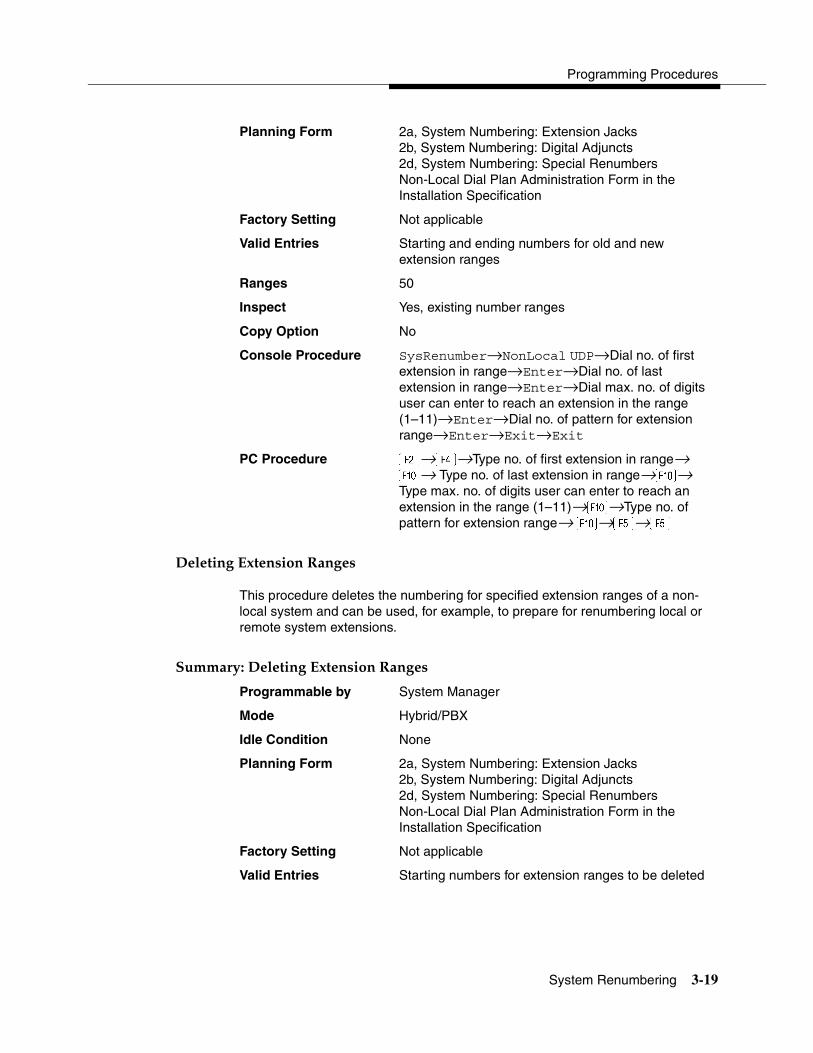
Programming Procedures
System Renumbering 3-19
Planning Form 2a, System Numbering: Extension Jacks2b, System Numbering: Digital Adjuncts2d, System Numbering: Special RenumbersNon-Local Dial Plan Administration Form in the Installation Specification
Factory Setting Not applicable
Valid Entries Starting and ending numbers for old and new extension ranges
Ranges 50
Inspect Yes, existing number ranges
Copy Option No
Console Procedure SysRenumber→NonLocal UDP→Dial no. of first extension in range→Enter→Dial no. of last extension in range→Enter→Dial max. no. of digits user can enter to reach an extension in the range (1–11)→Enter→Dial no. of pattern for extension range→Enter→Exit→Exit
PC Procedure �→→Type no. of first extension in range→ �→ Type no. of last extension in range→�→Type max. no. of digits user can enter to reach an extension in the range (1–11)→�→Type no. of pattern for extension range→ �→�→�
Deleting Extension Ranges 3
This procedure deletes the numbering for specified extension ranges of a non-local system and can be used, for example, to prepare for renumbering local or remote system extensions.
Summary: Deleting Extension Ranges 3
Programmable by System Manager
Mode Hybrid/PBX
Idle Condition None
Planning Form 2a, System Numbering: Extension Jacks2b, System Numbering: Digital Adjuncts2d, System Numbering: Special RenumbersNon-Local Dial Plan Administration Form in the Installation Specification
Factory Setting Not applicable
Valid Entries Starting numbers for extension ranges to be deleted

System Programming
3-20 System Renumbering
Inspect Yes: existing number ranges
Copy Option No
Console Procedure SysRenumber→NonLocal UDP→Dial no. of first extension in range→Enter→DelRange→Exit→ Exit
PC Procedure �→→Type no. of first extension in range→�→�→�→�
Direct Station Selector (DSS) Page Buttons 3
Use this procedure to set the three Page buttons on the DSS to correspond to the system numbering plan. This procedure assigns extension numbers to DSS buttons. You cannot program individual buttons on a DSS; this is the only method for programming DSS buttons.
Page button assignment should be sequential. If only one DSS is attached, each Page button assignment sets the console for a range of 50 extension numbers: Page 1: 0 to 49; Page 2: 50 to 99; Page 3: 100 to 149.
If two DSSs are attached, each Page button assignment sets the console for a range of 100 extension numbers. If two DSSs are attached to the console, change the factory setting so that the difference between extension numbers assigned to the range is at least 100. For example, assign Page 1 to begin with extension 10, Page 2 to begin with extension 110, and Page 3 to begin with extension 210.
Operator Park Zone codes must be included in the extension number range specified for one of the Page buttons.
! CAUTION:Select Exit on the console, or � on the PC, when you have finished this procedure. If you press Home, extensions may remain in the forced idle condition (the LED next to each DSS button is on), and the system may have to be restarted.
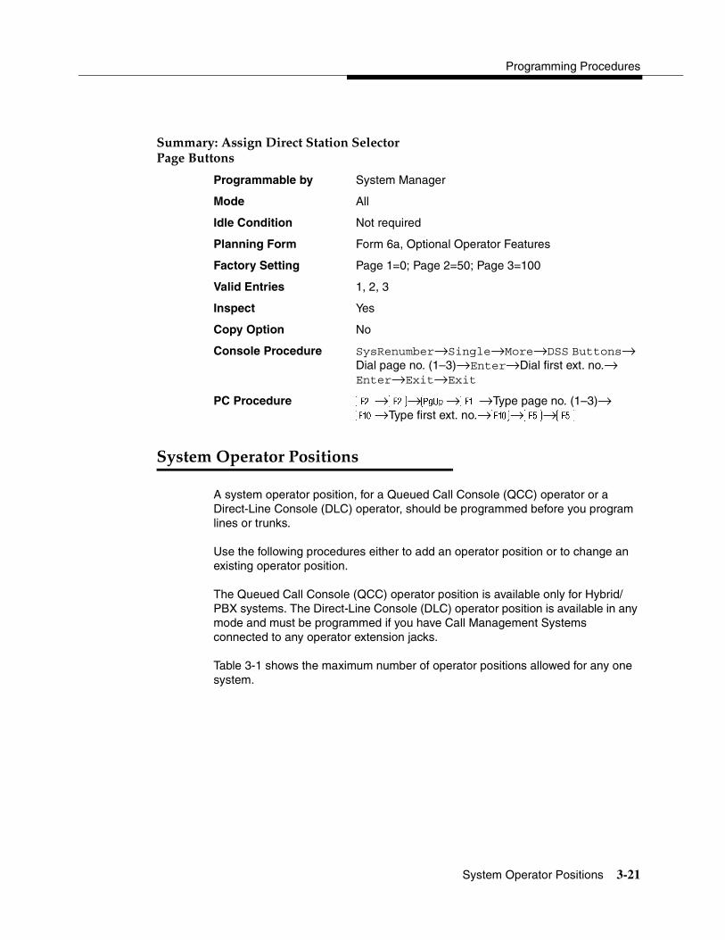
Programming Procedures
System Operator Positions 3-21
Summary: Assign Direct Station Selector Page Buttons 3
Programmable by System Manager
Mode All
Idle Condition Not required
Planning Form Form 6a, Optional Operator Features
Factory Setting Page 1=0; Page 2=50; Page 3=100
Valid Entries 1, 2, 3
Inspect Yes
Copy Option No
Console Procedure SysRenumber→Single→More→DSS Buttons→ Dial page no. (1–3)→Enter→Dial first ext. no.→ Enter→Exit→Exit
PC Procedure �→�→�→�→Type page no. (1–3)→ �→Type first ext. no.→�→�→�
System Operator Positions 3
A system operator position, for a Queued Call Console (QCC) operator or a Direct-Line Console (DLC) operator, should be programmed before you program lines or trunks.
Use the following procedures either to add an operator position or to change an existing operator position.
The Queued Call Console (QCC) operator position is available only for Hybrid/PBX systems. The Direct-Line Console (DLC) operator position is available in any mode and must be programmed if you have Call Management Systems connected to any operator extension jacks.
Table 3-1 shows the maximum number of operator positions allowed for any one system.
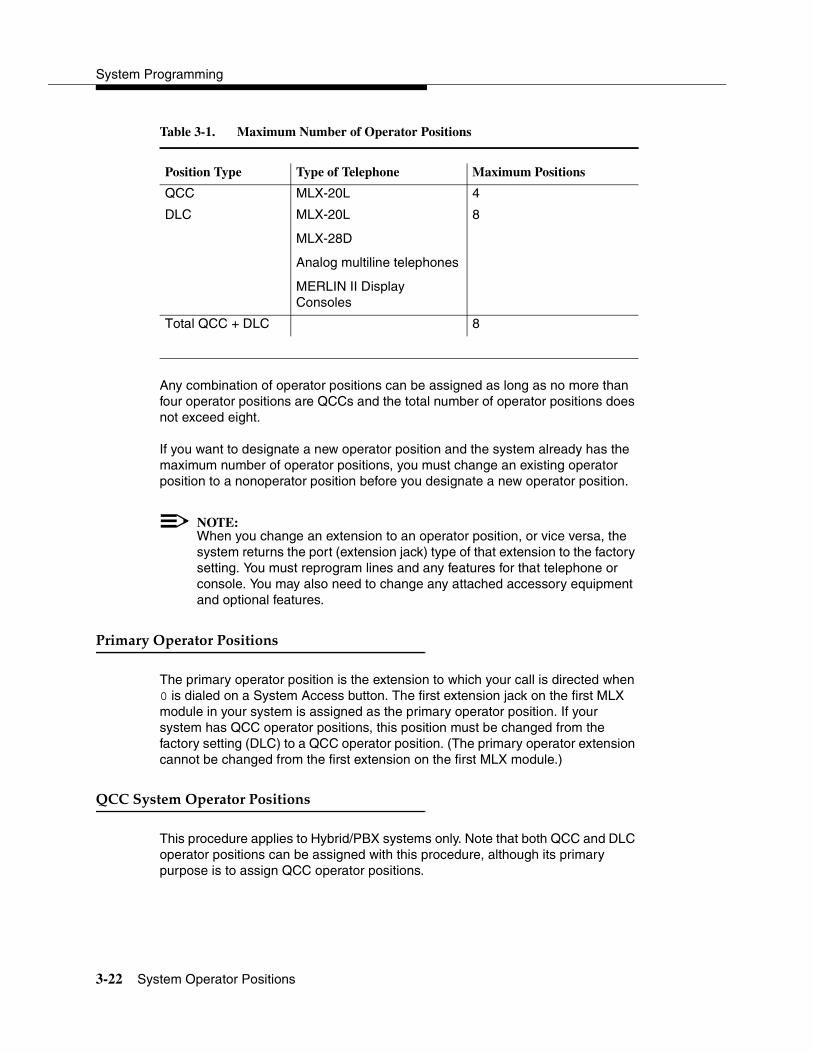
System Programming
3-22 System Operator Positions
Table 3-1. Maximum Number of Operator Positions
Any combination of operator positions can be assigned as long as no more than four operator positions are QCCs and the total number of operator positions does not exceed eight.
If you want to designate a new operator position and the system already has the maximum number of operator positions, you must change an existing operator position to a nonoperator position before you designate a new operator position.
NOTE:When you change an extension to an operator position, or vice versa, the system returns the port (extension jack) type of that extension to the factory setting. You must reprogram lines and any features for that telephone or console. You may also need to change any attached accessory equipment and optional features.
Primary Operator Positions 3
The primary operator position is the extension to which your call is directed when 0 is dialed on a System Access button. The first extension jack on the first MLX module in your system is assigned as the primary operator position. If your system has QCC operator positions, this position must be changed from the factory setting (DLC) to a QCC operator position. (The primary operator extension cannot be changed from the first extension on the first MLX module.)
QCC System Operator Positions 3
This procedure applies to Hybrid/PBX systems only. Note that both QCC and DLC operator positions can be assigned with this procedure, although its primary purpose is to assign QCC operator positions.
Position Type Type of Telephone Maximum Positions
QCC MLX-20L 4
DLC MLX-20L
MLX-28D
Analog multiline telephones
MERLIN II Display Consoles
8
Total QCC + DLC 8

Programming Procedures
System Operator Positions 3-23
QCC operators serve as central answering positions for all incoming calls. Incoming calls are held in the QCC queue and are directed to each QCC operator in a prioritized sequence. The calls are received one at a time, regardless of the number of incoming calls to the system.
Additional QCC operator positions can be assigned only to the first and fifth extension jacks of the MLX modules. A maximum of four QCC operator positions can be assigned. Use this procedure to specify QCC operator positions that serve as central answering positions for all incoming calls.
NOTE:If you want to add or remove QCC operator positions, the following conditions apply:
� If other QCC positions remain in your system, the primary QCC operator position cannot be removed.
� When QCC operator positions are added, the primary QCC operator position should be the first one added.
� If QCC operator positions are being removed, the primary QCC operator position must be the last one removed.
Summary: QCC Operator Positions 3
Programmable by System Manager
Mode All
Idle Condition System idle
Planning Form 2a, System Numbering: Extension Jacks
Factory Setting Type: DLC
Valid Entries First or fifth extension jack on MLX module (maximum: two per module; four QCCs per system).First, fifth, ninth, or thirteenth extension jack on the 016 MLX module (Release 7.0 and later).
Inspect Yes
Copy Option No
Console Procedure Operator→Positions→Queued Call→Dial ext. no.→ Enter or Delete→Store All
PC Procedure →�→�→Type ext. no.→� or �→

System Programming
3-24 System Operator Positions
DLC Operator Positions 3
DLC operator positions can be assigned to the first and fifth extension jacks on the first modules with either digital or analog multiline extension jacks. A maximum of eight DLC operator positions can be assigned. Any combination of operator positions can be assigned as long as there are no more than four QCC operator positions and no more than a total of eight operator positions.
Use this procedure to specify extensions that serve as central answering positions for all incoming calls, either for Call Management Systems (CMSs) connected to operator extension jacks, or as calling group supervisor extensions. (You do not need to use this procedure in a Key or Behind Switch system unless you have more than one DLC position.) For a new system, remove the factory-set DLC operator position assignment for any telephone not used as an operator position.
Lines and trunks are assigned to individual buttons.
The system programming console can have several incoming calls ringing simultaneously.
Each CMS requires two DLC operator positions to connect the equipment and one position to serve as CMS supervisor.
Summary: Identify or Remove DLC Operator Positions 3
Programmable by System Manager
Mode All
Idle Condition System idle
Planning Form 2a, System Numbering: Extension Jacks
Factory Setting Type: DLC
Valid Entries First or fifth extension jack on MLX module (maximum: two per module; maximum: eight DLCs per system)
Inspect Yes
Copy Option No
Console Procedure Operator→Positions→Direct Line→Dial ext. no.→ Enter or Delete→Store All
PC Procedure →�→�→Type ext. no.→� or �→
Programming Procedures
Lines and Trunks 3-25
Lines and Trunks 3
The procedures in this section are used to assign optional features to individual lines and trunks. The following optional features can be assigned:
� Type of Trunk
� Outmode Signaling for Loop- or Ground-Start Trunks
� Rotary Trunk Digit Transfer
� Disconnect Signaling Reliability
� Toll Type
� Hold Disconnect Interval
� Principal User for Personal Line
� QCC Queue Priority
� QCC Operator to Receive Calls
� Incoming Call Line Identification Delay
� Trunks to Pools Assignment
The Copy Options feature (described at the end of this section) allows you to copy several optional features from an idle trunk. This option eliminates the need to individually enter each feature.
Separate sections cover ‘‘DS1 Facilities,” ‘‘Tie Trunks,” ‘‘DID Trunks,”‘‘PRI Facilities,” and ‘‘BRI Facilities.”
A slot is the physical location of the individual module on the control unit. There is a maximum of 17 slots, which are numbered as follows:
� Basic carrier: slots 1 through 5
� First expansion carrier: slots 6 through 11
� Second expansion carrier: slots 12 through 17
A port is a line or trunk jack on the module. Individual modules support different numbers of ports. On any module, port 1 is the lowest physical jack position. For modules with both line and extension jacks, the port numbers for the line jacks follow the numbers for the extension jacks instead of beginning with 1. For example, for a 408 LS-ID-MLS module, the port numbers for the extension jacks are 01 through 08 and the port numbers for the line jacks are 09 through 12.

System Programming
3-26 Lines and Trunks
Type of Trunk 3
Use this procedure to specify the type of trunk, loop-start (LS) or ground-start (GS), for each outside trunk connected to one of the following modules:
� 400 GS/LS
� 408 GS/LS
� 408 GS/LS-MLX
� 408 GS/LS-ID-MLX
� 800 GS/LS
� 800 GS/LS-ID (loop-start trunks only)
� 412 LS-ID-ETR
Any combination of trunk types (all loop-start, all ground-start, or some of each) is permissible.
This procedure is not used for a system registered with a KF registration number (Key or Behind Switch). Ground-start trunks are allowed only for systems with an MF (Hybrid) or PF (PBX) registration number.
Summary: Type of Trunk 3
Programmable by System Manager
Mode All
Idle Condition Not required
Planning Form 2c, System Numbering: Line/Trunk Jacks
Factory Setting All Loop-Start
Valid Entries All Ground, All Loop, Ground-Start, Loop-Start
Inspect Yes
Copy Option Yes
Console Procedure LinesTrunks→LS/GS/DS1→Dial slot no. (1–17)→ Enter→Select trunk type (all ground, all loop, ground-start, or loop-start)→Dial port no.→ Enter→Exit→Exit
PC Procedure →�→Type slot no. (1–17)→�→Select trunk type (all ground, all loop, ground-start, or loop-start)→Type port no.→�→�→�

Programming Procedures
Lines and Trunks 3-27
Outmode Signaling for Loop- or Ground-Start Trunks 3
Use this procedure to identify either touch-tone signaling or rotary-dial signaling for outgoing calls placed by using the specified loop- or ground-start trunk.
NOTE:Since the factory setting is touch-tone, this procedure is not required if your system has only touch-tone lines/trunks.
Summary: Outmode Signaling for Loop- orGround-Start Trunks 3
Programmable by System Manager
Mode Loop-Start: All; Ground-Start: Hybrid/PBX only
Idle Condition Not required
Planning Form 2c, System Numbering: Line/Trunk Jacks
Factory Setting Touch-tone
Valid Entries Touch-tone, Rotary
Inspect No
Copy Option Yes
Console Procedure To program a single line/trunk:LinesTrunks→TT/LS Disc→Outmode→Select entry mode (touch-tone or rotary)→Dial no. of line/trunk→Enter or Delete→Exit→Exit→Exit
To program a block of lines/trunks:LinesTrunks→TT/LS Disc→OutMode→Select block of lines/trunks→Toggle LED on/off→Enter or Delete→ Exit→Exit→Exit
PC Procedure To program a single line/trunk:→→�→� (touch-tone or rotary)→ Type no. of the line/trunk→� or �→�→�→�
To program a block of lines/trunks:→→�→Select block of lines/trunks→Toggle letter G on/off→� or�→�→�→�

System Programming
3-28 Lines and Trunks
Rotary Trunk Digit Transfer 3
Use this procedure to designate whether dialed digits on rotary-dial lines/trunks are sent one by one as they are dialed (no delay), or are stored and sent when dialing is completed (delay). Contact your service provider for more information about the appropriate setting.
Summary: Rotary Trunk Digit Transfer 3
Programmable by System Manager
Mode All
Idle Condition Not required
Planning Form Form 8a, System Features
Factory Setting No Delay
Valid Entries Delay, No Delay
Inspect No
Copy Option No
Console Procedure Options→More→Rotary→Select option (delay or no delay)→ Enter→Exit
PC Procedure �→�→→Select option (delay or no delay)→�→�
Ringing Frequency 3
Use this procedure to program the ringing frequency on an 016 (T/R) module. Contact your service provider for more information about the appropriate setting. The 016 (T/R) module is available only in Release 4.0 and later.
Summary: Ringing Frequency 3
Programmable by System Manager
Mode All
Idle Condition Not required
Planning Form Form 8a, System Features
Factory Setting 20 Hz
Valid Entries 20 Hz, 25 Hz
Inspect No
Copy Option No
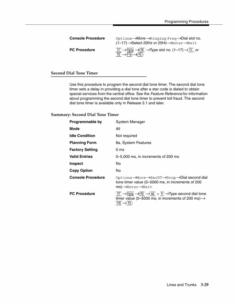
Programming Procedures
Lines and Trunks 3-29
Console Procedure Options→More→Ringing Freq→Dial slot no. (1–17)→Select 20Hz or 25Hz→Enter→Exit
PC Procedure �→�→�→Type slot no. (1–17)→� or�→�→�
Second Dial Tone Timer 3
Use this procedure to program the second dial tone timer. The second dial tone timer sets a delay in providing a dial tone after a star code is dialed to obtain special services from the central office. See the Feature Reference for information about programming the second dial tone timer to prevent toll fraud. The second dial tone timer is available only in Release 3.1 and later.
Summary: Second Dial Tone Timer 3
Programmable by System Manager
Mode All
Idle Condition Not required
Planning Form 8a, System Features
Factory Setting 0 ms
Valid Entries 0–5,000 ms, in increments of 200 ms
Inspect No
Copy Option No
Console Procedure Options→More→SecDT→Drop→Dial second dial tone timer value (0–5000 ms, in increments of 200 ms)→Enter→Exit
PC Procedure �→�→�→� + �→Type second dial tone timer value (0–5000 ms, in increments of 200 ms)→ �→�
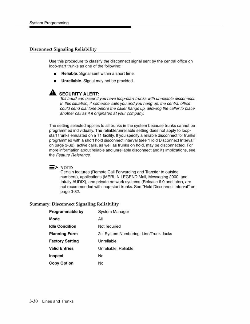
System Programming
3-30 Lines and Trunks
Disconnect Signaling Reliability 3
Use this procedure to classify the disconnect signal sent by the central office on loop-start trunks as one of the following:
� Reliable. Signal sent within a short time.
� Unreliable. Signal may not be provided.
! SECURITY ALERT:Toll fraud can occur if you have loop-start trunks with unreliable disconnect. In this situation, if someone calls you and you hang up, the central office could send dial tone before the caller hangs up, allowing the caller to place another call as if it originated at your company.
The setting selected applies to all trunks in the system because trunks cannot be programmed individually. The reliable/unreliable setting does not apply to loop-start trunks emulated on a T1 facility. If you specify a reliable disconnect for trunks programmed with a short hold disconnect interval (see ‘‘Hold Disconnect Interval’’ on page 3-32), active calls, as well as trunks on hold, may be disconnected. For more information about reliable and unreliable disconnect and its implications, see the Feature Reference.
NOTE:Certain features (Remote Call Forwarding and Transfer to outside numbers), applications (MERLIN LEGEND Mail, Messaging 2000, and Intuity AUDIX), and private network systems (Release 6.0 and later), are not recommended with loop-start trunks. See ‘‘Hold Disconnect Interval’’ on page 3-32.
Summary: Disconnect Signaling Reliability 3
Programmable by System Manager
Mode All
Idle Condition Not required
Planning Form 2c, System Numbering: Line/Trunk Jacks
Factory Setting Unreliable
Valid Entries Unreliable, Reliable
Inspect No
Copy Option No
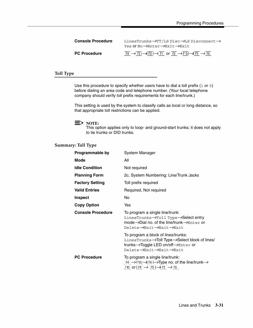
Programming Procedures
Lines and Trunks 3-31
Console Procedure LinesTrunks→TT/LS Disc→LS Disconnect→ Yes or No→Enter→Exit→Exit
PC Procedure →→�→� or�→�→�→�
Toll Type 3
Use this procedure to specify whether users have to dial a toll prefix (1 or 0) before dialing an area code and telephone number. (Your local telephone company should verify toll prefix requirements for each line/trunk.)
This setting is used by the system to classify calls as local or long distance, so that appropriate toll restrictions can be applied.
NOTE:This option applies only to loop- and ground-start trunks; it does not apply to tie trunks or DID trunks.
Summary: Toll Type 3
Programmable by System Manager
Mode All
Idle Condition Not required
Planning Form 2c, System Numbering: Line/Trunk Jacks
Factory Setting Toll prefix required
Valid Entries Required, Not required
Inspect No
Copy Option Yes
Console Procedure To program a single line/trunk:LinesTrunks→Toll Type→Select entry mode→Dial no. of the line/trunk→Enter or Delete→Exit→Exit→Exit
To program a block of lines/trunks:LinesTrunks→Toll Type→Select block of lines/trunks→Toggle LED on/off→Enter or Delete→Exit→Exit→Exit
PC Procedure To program a single line/trunk:→�→�→Type no. of the line/trunk→� or �→ �→�→�

System Programming
3-32 Lines and Trunks
To program a block of lines/trunks:→�→Select block of lines/trunk→Toggle letter G→on/off→� or �→�→�→�
Hold Disconnect Interval 3
Use this procedure to specify the number of milliseconds before a loop-start line/trunk is released when a caller on hold hangs up and abandons the call. This can be specified as either a long interval (450 ms) or a short interval (50 ms). The hold disconnect interval applies to loop-start trunks; it does not apply to emulated loop-start trunks (T1 facility).
NOTES:� If the disconnect interval is longer than the telephone company setting,
the line is not released when a caller on hold hangs up.
� Do not program a short interval unless the local telephone company’s central office is the crossbar type.
� Do not program a reliable disconnect for lines/trunks with a short hold disconnect interval. This can cause active calls as well as lines/trunks on hold to be disconnected. See ‘‘Disconnect Signaling Reliability’’ on page 3-30.
For more information on Hold Interval Disconnect and Reliable and Unreliable Disconnect, see the Feature Reference.
Summary: Hold Disconnect Interval 3
Programmable by System Manager
Mode All
Idle Condition Not required
Planning Form 2c, System Numbering: Line/Trunk Jacks
Factory Setting Long interval (450 ms)
Valid Entries Long interval, Short interval
Inspect No
Copy Option No
Console Procedure To program a single line/trunk:LinesTrunks→More→HoldDiscnct→Select entry mode→ Dial no. of the line/trunk→ Enter→Exit→Exit

Programming Procedures
Lines and Trunks 3-33
To program a block of lines/trunks:LinesTrunks→More→HoldDiscnct→Select block of lines/trunks→Toggle LED on/off→Enter→Exit→Exit
PC Procedure To program a single line/trunk:→�→�→�→Type no. of the line/trunk→�→�→�
To program a block of lines/trunks:→�→�→Select block of lines/trunks→ Toggle letter G on/off→�→�→�
Principal User for Personal Line 3
Use this procedure to assign or remove one telephone as principal user for a personal line. When a telephone with Remote Call Forwarding activated is assigned as principal user, calls received on the personal line are forwarded to an outside telephone number. In addition, calls received on that line are sent to that telephone’s individual and/or Group Coverage receivers unless the personal line button is set to No Ring.
The principal user assignment must be removed before the trunk can be removed from a button on the telephone.
When no principal user is assigned for a personal line, calls received on the personal line are not forwarded to outside telephone numbers; calls received on the personal line follow the coverage patterns for all users who share the line.
Summary: Principal User for Personal Line 3
Programmable by System Manager
Mode All
Idle Condition Not required
Planning Form 4b, Analog Multiline Telephone4d, MLX Telephone4e, MFM Adjunct: MLX telephone4f, Tip/Ring Equipment5a, Direct-Line Console (DLC): Analog5b, Direct-Line Console (DLC): Digital5c, MFM Adjunct: DLC
Factory Setting No principal user
Valid Entries Not applicable
Inspect No
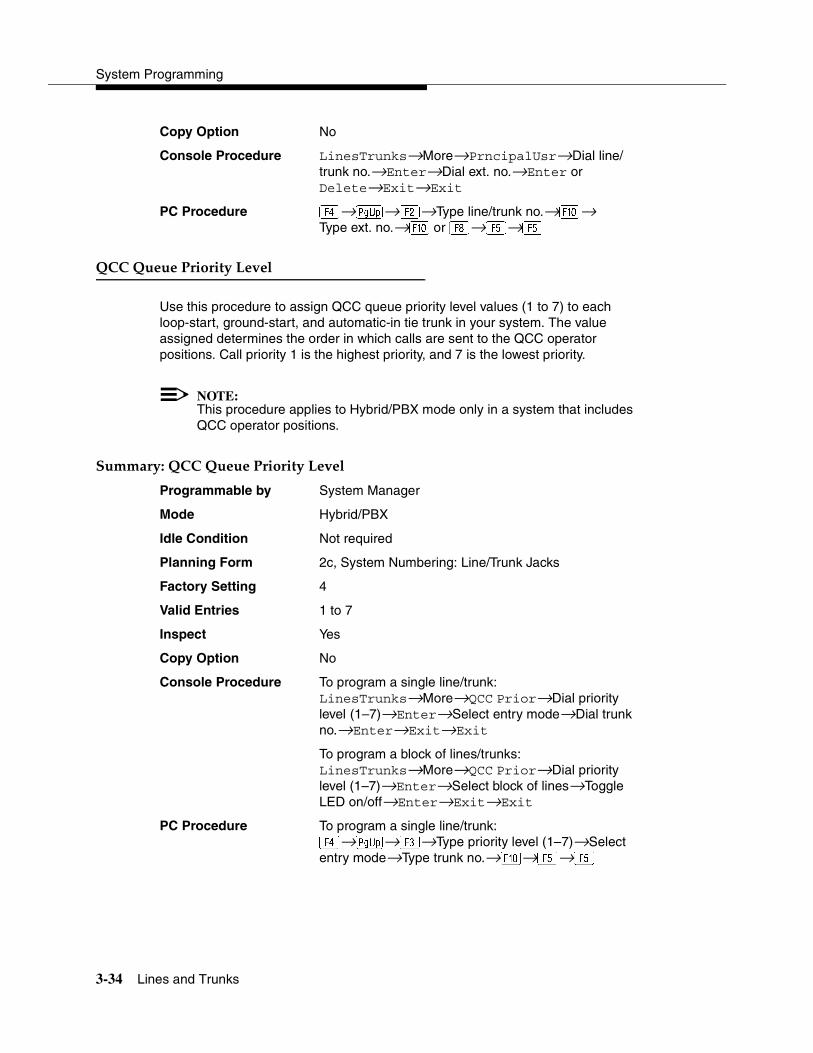
System Programming
3-34 Lines and Trunks
Copy Option No
Console Procedure LinesTrunks→More→PrncipalUsr→Dial line/trunk no.→Enter→Dial ext. no.→Enter or Delete→Exit→Exit
PC Procedure →�→�→Type line/trunk no.→�→Type ext. no.→� or �→�→�
QCC Queue Priority Level 3
Use this procedure to assign QCC queue priority level values (1 to 7) to each loop-start, ground-start, and automatic-in tie trunk in your system. The value assigned determines the order in which calls are sent to the QCC operator positions. Call priority 1 is the highest priority, and 7 is the lowest priority.
NOTE:This procedure applies to Hybrid/PBX mode only in a system that includes QCC operator positions.
Summary: QCC Queue Priority Level 3
Programmable by System Manager
Mode Hybrid/PBX
Idle Condition Not required
Planning Form 2c, System Numbering: Line/Trunk Jacks
Factory Setting 4
Valid Entries 1 to 7
Inspect Yes
Copy Option No
Console Procedure To program a single line/trunk:LinesTrunks→More→QCC Prior→Dial priority level (1–7)→Enter→Select entry mode→Dial trunk no.→Enter→Exit→Exit
To program a block of lines/trunks:LinesTrunks→More→QCC Prior→Dial priority level (1–7)→Enter→Select block of lines→Toggle LED on/off→Enter→Exit→Exit
PC Procedure To program a single line/trunk:→�→→Type priority level (1–7)→Select entry mode→Type trunk no.→�→�→�
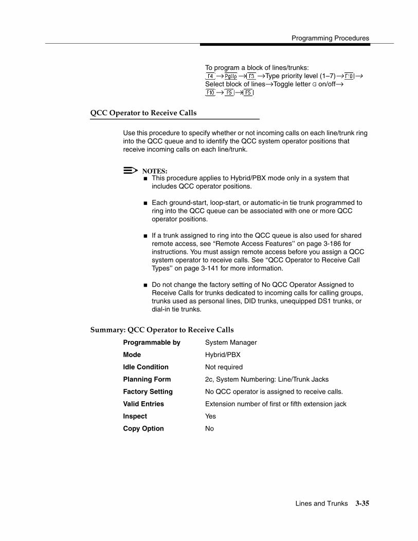
Programming Procedures
Lines and Trunks 3-35
To program a block of lines/trunks:→�→→Type priority level (1–7)→�→Select block of lines→Toggle letter G on/off→�→�→�
QCC Operator to Receive Calls 3
Use this procedure to specify whether or not incoming calls on each line/trunk ring into the QCC queue and to identify the QCC system operator positions that receive incoming calls on each line/trunk.
NOTES:� This procedure applies to Hybrid/PBX mode only in a system that
includes QCC operator positions.
� Each ground-start, loop-start, or automatic-in tie trunk programmed to ring into the QCC queue can be associated with one or more QCC operator positions.
� If a trunk assigned to ring into the QCC queue is also used for shared remote access, see ‘‘Remote Access Features’’ on page 3-186 for instructions. You must assign remote access before you assign a QCC system operator to receive calls. See ‘‘QCC Operator to Receive Call Types’’ on page 3-141 for more information.
� Do not change the factory setting of No QCC Operator Assigned to Receive Calls for trunks dedicated to incoming calls for calling groups, trunks used as personal lines, DID trunks, unequipped DS1 trunks, or dial-in tie trunks.
Summary: QCC Operator to Receive Calls 3
Programmable by System Manager
Mode Hybrid/PBX
Idle Condition Not required
Planning Form 2c, System Numbering: Line/Trunk Jacks
Factory Setting No QCC operator is assigned to receive calls.
Valid Entries Extension number of first or fifth extension jack
Inspect Yes
Copy Option No
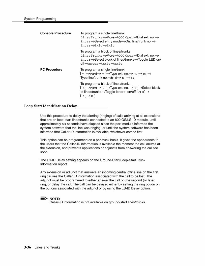
System Programming
3-36 Lines and Trunks
Console Procedure To program a single line/trunk:LinesTrunks→More→QCC Oper→Dial ext. no.→ Enter→Select entry mode→Dial line/trunk no.→ Enter→Exit→Exit
To program a block of lines/trunks:LinesTrunks→More→QCC Oper→Dial ext. no.→ Enter→Select block of lines/trunks→Toggle LED on/off→Enter→Exit→Exit
PC Procedure To program a single line/trunk:→�→→Type ext. no.→�→�→ Type line/trunk no.→�→�→�
To program a block of lines/trunks:→�→→Type ext. no.→�→Select block of lines/trunks→Toggle letter G on/off→�→ �→�
Loop-Start Identification Delay 3
Use this procedure to delay the alerting (ringing) of calls arriving at all extensions that are on loop-start lines/trunks connected to an 800 GS/LS-ID module, until approximately six seconds have elapsed since the port module informed the system software that the line was ringing, or until the system software has been informed that Caller ID information is available, whichever comes first.
This option can be programmed on a per-trunk basis. It gives the appearance to the users that the Caller-ID information is available the moment the call arrives at the extension, and prevents applications or adjuncts from answering the call too soon.
The LS-ID Delay setting appears on the Ground-Start/Loop-Start Trunk Information report.
Any extension or adjunct that answers an incoming central office line on the first ring causes the Caller ID information associated with the call to be lost. The adjunct must be programmed to either answer the call on the second (or later) ring, or delay the call. The call can be delayed either by setting the ring option on the buttons associated with the adjunct or by using the LS-ID Delay option.
NOTE:Caller-ID information is not available on ground-start lines/trunks.

Programming Procedures
Lines and Trunks 3-37
Summary: Loop-Start Identification Delay 3
Programmable by System Manager
Mode All
Idle Condition Not required
Planning Form 2c, System Numbering: Line/Trunk Jacks
Factory Setting No delay
Valid Entries Loop-start line/trunk numbers
Inspect Yes
Copy Option Yes, but only to the same trunk type
Console Procedure To program a single line/trunk:LinesTrunks→More→LS-ID Delay→Select entry mode→ Dial no. of the line/trunk→Enter→Exit→ Exit
To program a block of lines/trunks:LinesTrunks→More→LS-ID Delay→Select block of lines/trunks→Toggle LED on/off→Enter→Exit→ Exit
PC Procedure To program a single line/trunk:→�→�→�→Type no. of the line/trunk→ �→�→�
To program a block of lines/trunks:→�→�→Select block of lines/trunks→ Toggle letter G on/off→�→�→�
Clock Synchronization 3
NOTE:The following information is for planning clock synchronization in systems that are not part of a private network. For planning clock synchronization in a private network configuration, see the Network Reference.
Use this procedure to specify the primary, secondary, and tertiary clock source. A clock source may be either a 100D module or a port on an 800 NI-BRI module. See the Feature Reference for more information about the appropriate setting. If the clock is taken from a 100D module, you can also specify whether the clock is synchronized to the outside endpoint (loop) or to the clock reference source (local).

System Programming
3-38 Lines and Trunks
NOTE:This procedure is necessary only if your system includes an 800 NI-BRI module or more than one 100D module.
Summary: Clock Synchronization 3
Programmable by System Manager
Mode All
Idle Condition Not required
Planning Form 3b, Incoming Trunks: DS1 Connectivity 100D module3i, Incoming Trunks: BRI Options
Factory Setting Primary clock: the first 100D module in the control unit carrier
Valid Entries Primary, Secondary, Tertiary, Loop/Local
Inspect No
Copy Option No
Console Procedure LinesTrunks→More→ClockSync→Primary→Dial slot no. (1–17)→Enter→Dial port no. or select source of synchronization→ Enter→ Secondary→ Dial slot no. (1–17)→Enter→Dial port no. or select source of synchronization→ Enter→ Tertiary→ Dial slot no. (1–17)→Enter→Dial port no. or select source of synchronization→ Enter→Exit→Exit
PC Procedure →�→�→�→Type slot no. (1–17)→ �→Type port no. or select source of synchronization→�→ �→Type slot no. (1–17)→ �→Type port no. or select source of synchronization→�→→Type slot no. (1–17)→ �→Type port no. or select source of synchronization→�→�→�
Trunks to Pools Assignment 3
Use this procedure to create trunk pools (groups of outside lines/trunks connected to the system). Trunk pools are used to specify preferred routes for Automatic Route Selection (ARS). In addition, trunk pools enable users to select a line/trunk by dialing a pool dial-out code or by pressing a single button on the telephone. (A separate button for each line/trunk is not needed.) Each pool should contain trunks of the same type (for example, loop- or ground-start or WATS); however, ground- and loop-start trunks of the same type can be included in the same pool.

Programming Procedures
Lines and Trunks 3-39
Ground-start trunks must be manually assigned. A maximum of 11 trunk pools is allowed. A trunk can be assigned to only one pool.
Do not mix different service areas of WATS (Wide Area Telecommunications Service) trunks or FX (Foreign Exchange) lines to different cities. Do not include both incoming-only and outgoing-only lines/trunks in the same pool.
In Release 6.0 and later systems (Hybrid/PBX mode only), when dialing 10*** and 101**** equal access (Interexchange Carrier or IXC) calls via a private networked switch that is not connected to the public switched network, the private trunks must be assigned to the main pool. When routing Dial 0 and N11 calls via this type of networked switch, the private trunks must be assigned to the main pool containing private network trunks. For more information, see ‘‘Automatic Route Selection’’ on page 3-197.
If you want to reassign a line/trunk to a different pool, you must remove it from the current pool before you assign it to the new pool. Once you assign a line/trunk to a pool, it can be assigned to a button only on a direct-line console operator position; individual lines intended for personal use on telephones other than the DLC console should not be assigned to pools.
DID trunks cannot be grouped in pools. Loop-start trunks are automatically placed in pools and must be removed manually if used for paging loudspeakers, Music-On-Hold, or maintenance alarms.
Dial-in tie trunks should not be grouped in pools if you intend to assign Pool buttons on telephones.
! SECURITY ALERT:In Release 6.0 and later systems (Hybrid/PBX mode only), do not assign pools of non-local tie or PRI tandem trunks to Pool buttons or DSS buttons, or allow dial access to them. When callers in your system need to use these pools for outside calls, use ARS to direct the calls to these pools. Callers in your system use normal calling procedures to reach extensions on private networked systems.
If you are using Automatic Route Selection, the main pool (factory-set dial-out code 70) must contain loop- or ground-start trunks.
The system provides an error tone when a line/trunk is in use, or if a loudspeaker paging system, Music-On-Hold, or maintenance alarm is already assigned; however, the system does not indicate the reason for the error tone.
NOTE:This procedure applies to Hybrid/PBX mode only.
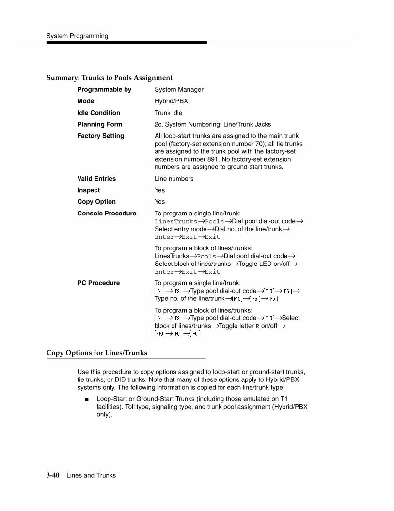
System Programming
3-40 Lines and Trunks
Summary: Trunks to Pools Assignment 3
Programmable by System Manager
Mode Hybrid/PBX
Idle Condition Trunk idle
Planning Form 2c, System Numbering: Line/Trunk Jacks
Factory Setting All loop-start trunks are assigned to the main trunk pool (factory-set extension number 70); all tie trunks are assigned to the trunk pool with the factory-set extension number 891. No factory-set extension numbers are assigned to ground-start trunks.
Valid Entries Line numbers
Inspect Yes
Copy Option Yes
Console Procedure To program a single line/trunk:LinesTrunks→Pools→Dial pool dial-out code→ Select entry mode→Dial no. of the line/trunk→ Enter→Exit→Exit
To program a block of lines/trunks:LinesTrunks→Pools→Dial pool dial-out code→ Select block of lines/trunks→Toggle LED on/off→ Enter→Exit→Exit
PC Procedure To program a single line/trunk:→�→Type pool dial-out code→�→�→Type no. of the line/trunk→�→�→�
To program a block of lines/trunks:→�→Type pool dial-out code→�→Select block of lines/trunks→Toggle letter R on/off→�→�→�
Copy Options for Lines/Trunks 3
Use this procedure to copy options assigned to loop-start or ground-start trunks, tie trunks, or DID trunks. Note that many of these options apply to Hybrid/PBX systems only. The following information is copied for each line/trunk type:
� Loop-Start or Ground-Start Trunks (including those emulated on T1 facilities). Toll type, signaling type, and trunk pool assignment (Hybrid/PBX only).
Programming Procedures
Lines and Trunks 3-41
� Tie Trunks. Direction, tie trunk type, E&M signal, dial mode, dial tone, answer supervision time, disconnect time, and trunk pool assignment (Hybrid/PBX only).
� DID Trunks (Hybrid/PBX only). Block assignment and disconnect time.
To find out whether there is an optional feature assigned that you would like to copy, use Inspct from the system programming console, or � on a PC.
NOTES:� You can copy options to a block of lines/trunks only if they are all of the
same type (loop-start, ground-start, Tie, or DID). If you attempt to copy assignments and there is a mismatch in line/trunk type, information is copied to that point only. You receive no error message.
� In Release 6.0 and later systems, options cannot be copied from private lines/trunks.
� If you are copying options to a block of lines/trunks, they must be sequentially numbered.
� If the block you are copying to includes an invalid line/trunk type, the copying process stops at the invalid type. Only the lines/trunks that were copied to before the invalid type was found are copied successfully.
� If you are copying assignments to a block of lines/trunks and one of the lines or trunks is in use, you see the message Trunk Busy - Pls wait on your display. The copying for the rest of the lines/trunks in the block is delayed until the busy line/trunk becomes idle. If you exit without waiting for the copying to complete, the copying done up to that point is not canceled.
Summary: Copy Options for Lines/Trunks 3
Programmable by System Manager
Mode All (but note differences)
Idle Condition Not required
Planning Form 2c, System Numbering: Line/Trunk Jacks 3c, Incoming Trunks: TIE3d, Incoming Trunks: DID
Factory Setting Not applicable
Valid Entries Not applicable
Inspect No
Copy Option Not applicable

System Programming
3-42 Uniform Dial Plan Facilities
Console Procedure To copy individual lines/trunks:LinesTrunks→Copy→Single→Dial copy-from trunk no.→ Enter→Dial copy-to trunk no.→Enter→Exit→Exit→Exit
To copy blocks of lines/trunks:LinesTrunks→Copy→Block→Dial copy-from trunk no.→Enter→Dial first copy-to trunk no. in block→Enter→Dial last copy-to trunk no. in block→Enter→Exit→Exit→Exit
PC Procedure To copy individual lines/trunks:→�→�→Type copy to trunk no.→�→Type copy-from trunk no.→�→�→�→�
To copy blocks of lines/trunks:→�→�→Type copy-from trunk no.→Type first copy-to trunk no. in block→�→�→Type last copy-to trunk no. in block→�→�→�→�
Uniform Dial Plan Facilities 3
Release 6.0 and later systems, Hybrid/PBX mode only, provide support for Uniform Dial Plan (UDP) facilities, private network tandem lines/trunks originating at one or more other MERLIN LEGEND Communications Systems or DEFINITY Communications Systems. Use the procedures in this section to program the switch identifiers for private network trunks.
Switch Identifiers 3
Switch identifiers are 1- or 2-digit prefixes that appear in print reports and are used by the system for transmission level determination, route checking, and to identify calls. If your system uses private facilities, you must program switch identifiers. Switch identifiers indicate the switch connected to the far end of a private trunk.
The procedures in this topic allow you to add, change, and remove switch identifiers.
Trunks connected to your system from the central office do not require identifiers. They are, by default, correctly assigned a null identifier.
When a private networked trunk is deleted, it is assigned a null identifier, as are trunks newly added to the system.

Programming Procedures
Uniform Dial Plan Facilities 3-43
You can add a switch identifier to a block of trunks, and you can remove a switch identifier from a block of trunks that use the same switch identifier.
The correct switch identifier for a trunk or block of trunks is determined by the type of switch to which the trunk is connected and whether or not that switch is a satellite switch located within 200 miles of the local system. Identifying those switches greater than 200 miles from the local system as satellite is important in assuring transmission quality across the private network. The identifiers are switch numbers that have the following meanings:
� Unassigned (null) = trunk connected to central office
� 1–20 = trunk connected to a non-satellite MERLIN LEGEND Communications System greater than 200 miles
� 21–40 = trunk connected to a satellite MERLIN LEGEND Communications System
� 41–50 = trunk connected to a non-satellite, non-LEGEND system (for example, a DEFINITY Communications System) greater than 200 miles
� 51–60 = trunk connected to a satellite, non-LEGEND system (for example, a DEFINITY Communications System)
NOTE:The Enter Switch Number screens for the switch identifier procedures include a Help option that supplies the information above.
Wherever possible, the same switch identifiers should be used for the same switch across a private network. For example, LEGEND A is identified by switch identifier 22 in LEGEND B and LEGEND C systems in a private network. This helps avoid a situation where calls are directed in a loop through several systems. However, a trunk may connect to a switch that is a satellite for one networked system, but not a satellite for another networked system. In this case, a system may have more than one switch identifier. For example, LEGEND D may be located within 200 miles of LEGEND E, but more than 200 miles from LEGEND F in the same private network. In this case, the switch identifier for LEGEND D (for example, 21) as specified in LEGEND E is different from the identifier for LEGEND D (for example, 1) as specified in LEGEND F.
This topic includes procedures for adding a switch identifier to a single trunk or to a block of sequentially numbered trunks.

System Programming
3-44 Uniform Dial Plan Facilities
Summary: Switch Identifiers 3
Programmable by System Manager
Mode Hybrid/PBX
Idle Condition Not required
Planning Form 2c, System Numbering: Line/Trunk Jacks3b, Incoming Trunks: DS1 Connectivity (100D Module)
Factory Setting Null (no value)
Valid Entries no value, 1–20, 21–40, 41–50, 51–60
Inspect No
Copy Option No
Console Procedure To enter or remove an identifier for one trunk:LinesTrunks→More→UDP→SwNum-Single→Dial trunk no.→Enter→Dial switch no. (no value, 1–20, 21–40, 41–50, or 51–60)→Enter or Delete→ Exit→Exit→Exit
To enter or remove identifiers for a block of trunks:LinesTrunks→More→UDP→SwNum-Block→Dial starting trunk in block→Enter→Dial ending trunk in block→Enter→Dial switch no. (no value, 1–20, 21–40, 41–50, or 51–60)→Enter or Delete→ Exit→Exit→Exit
PC Procedure To enter or remove an identifier for one trunk:→�→�→�→Type trunk no.→�→Type switch no. (no value, 1–20, 21–40, 41–50, or 51–60)→� or �→�→�→�
To enter or remove identifiers for a block of trunks:→�→�→�→Type starting trunk in block→�→Type ending trunk in block→�→Type switch no. (no value, 1–20, 21–40, 41–50, or 51–60)→ � or �→�→�→�
Programming Procedures
DS1 Facilities 3-45
DS1 Facilities 3
Use the procedures in this section to program the following options for DS1 (digital signal level 1) facilities (T1 or PRI) connected to a 100D (DS1) module:
� Type of DS1 facility
— T1
— ISDN (Integrated Services Digital Network) Primary Rate Interface (PRI)
� Switched 56 Dial Plan Routing
� Frame Format
� Zero Code Suppression
� Signaling Mode
� Line Compensation
� Channel Service Unit
Type of DS1 Facility 3
Use this procedure to specify the type of facility (T1 or PRI) connected to a 100D (DS1) module. If T1 type is programmed, and the channels are used for emulation and/or AT&T Switched Network (ASN), you must specify the type of channel emulation.
NOTE:In Release 6.0 and later systems, you may order a point-to-point T1 circuit in order to provide amplification but not switching for a PRI tandem trunk that carries calls over long distances. PRI tandem trunks are preferable to T1 tandem trunks. Consult your Lucent Technologies representative for advice.
If the type is T1 and the type of channel emulation is tie trunk, you must specify whether the lines/trunks are TIE-PBX, Toll, or Switched 56 Data service. The valid settings are as follows:
� TIE-PBX. Select when emulated tie trunks are used to connect to another communications system (such as PBX or Centrex). For releases prior to Release 6.0, the transmit/receive parameter is set to 0/4.
� Toll. Select when emulated tie trunks are used for ASN services (such as Megacom‚ Megacom 800, or Software Defined Network). For releases prior to Release 6.0, the transmit/receive parameter is set to 0/6.

System Programming
3-46 DS1 Facilities
NOTE:The parameters listed in the two above items are for releases prior to Release 6.0. In Release 6.0 and later systems, the transmit/receive gains are determined by the call constituents.
� TIE – S56 Data. Select when emulated tie trunks are used for Switched 56 Data Service. Switched 56 Data Service is available only in Release 4.0 and later. The transmit/receive parameter is set to 0/0.
If the type is T1 and S56 Data Network Service is selected (available only in Release 4.0 and later), you must specify the following parameters:
� Direction. Specifies whether the trunk operates in one- or two-way direction. For one-way trunks, Outgoing Only or Incoming Only must also be specified.
� Trunk Seizure Type. Trunk seizure type is programmed independently for incoming or outgoing directions. Select one of the following: Wink Start, Delay Start, or Automatic Start.
� Answer Supervision Time. The time in milliseconds the answer supervision signal must be present to be considered valid.
� Disconnect Time. The time in milliseconds the disconnect signal must be present to be considered valid.
� Dial Mode. Select either Rotary or Touch-Tone. Dial mode is set independently for incoming or outgoing directions (Inmode or Outmode).
NOTE:Touch-Tone Receivers are required on the far-end switch when the setting is Touch-Tone.
Table 3-2 on page 3-49 shows the factory setting for each S56 Data Network Service option and the valid range for each threshold.
In Release 6.0 and later systems, T1 S56 service is not supported for tandeming applications. Use PRI instead.
If you select T1, channels can emulate ground- or loop-start trunks, tie trunks, or DID trunks in any combination. Note that unused channels must be specified as unequipped.
If either T1 or PRI is selected, channels can be used for ASN services. When T1 channels are used for ASN services, each channel must be programmed for tie trunk emulation.

Programming Procedures
DS1 Facilities 3-47
If you select PRI, you must perform additional procedures. At a minimum, the Framing Mode and Zero Code Suppression procedures must be performed. See ‘‘PRI Facilities’’ on page 3-67 for more information.
Summary: Type of DS1 Facility 3
Programmable by System Manager
Mode All
Idle Condition 100D module idle
Planning Form 2c, System Numbering: Line/Trunk Jacks3b, Incoming Trunks: DS1 Connectivity (100D module)
Factory Setting T1, see Table 3-2 on page 3-49 for options
Valid Entries T1, PRI
Inspect Yes
Copy Option No
Console Procedure To select PRI:LinesTrunks→LS/GS/DS1→Dial slot no. (1–17)→ Enter→Type→PRI→Enter→ Exit→ Exit→ Exit→Exit
To select T1: All Ground, All Loop, or All Unequip:LinesTrunks→LS/GS/DS1→Dial slot no. (1–17)→ Enter→ Type→ T1→Enter→Select type of emulation→Enter→Exit→Exit→Exit→Exit
To select T1: Ground-Start, Loop-Start, All Tie, or Unequip:LinesTrunks→LS/GS/DS1→Dial slot no. (1–17)→ Enter→Type→T1→Enter→Select type of emulation→Enter→Dial channel no.→ Enter→ Exit→Exit→Exit→Exit
To select T1: All DID:LinesTrunks→LS/GS/DS1→Dial slot no. (1–17)→ Enter→Type→T1→Enter→More→All DID→ Enter→Exit→Exit→Exit→Exit
To select T1: DID:LinesTrunks→LS/GS/DS1→Dial slot no. (1–17)→ Enter→Type→T1→Enter→More→DID→Enter→Dial channel no.→Enter→Exit→ Exit→ Exit→Exit

System Programming
3-48 DS1 Facilities
To select T1- All Tie:LinesTrunks→LS/GS/DS1→Dial slot no. (1–17)→ Enter→Type→T1→Enter→All TIE→Enter→ TIE-PBX, Toll, or S56→Enter→Dial channel no.→ Enter→Exit→Exit→Exit→Exit
To select T1- Tie:LinesTrunks→LS/GS/DS1→Dial slot no. (1–17)→ Enter→Type→T1→Enter→TIE→Enter→TIE-PBX, Toll, or S56→Enter→Dial channel no.→Enter→Exit→Exit→Exit→Exit
To select T1: All Switched 56 Data:LinesTrunks→LS/GS/DS1→Dial slot no. (1–17)→ Enter→Type→T1→Enter→More→ALL S56 Data→Enter→Select Direction, Intype, Outtype, AnsSupv, Disconnect, Inmode, or Outmode→Program options→ Enter→ Exit→Exit→Exit→Exit
To select T1: Switched 56 Data:LinesTrunks→LS/GS/DS1→Dial slot no. (1–17)→ Enter→ Type→T1→Enter→More→S56 Data→ Enter→Dial channel no.→Enter→Select Direction, Intype, Outtype, AnsSupv, Disconnect, Inmode, or Outmode→Program options→Enter→Exit→ Exit→Exit→Exit
PC Procedure To select PRI:→�→Type slot no. (1–17)→�→�→ �→�→�→�→�→�
To select T1: All Ground, All Loop, All Unequip:→�→Type slot no. (1–17)→�→ �→ �→ �→�→Select type of emulation→ �→�→�→�→�
To select T1: Ground-Start, Loop-Start, All Tie, or Unequip:→�→Type slot no. (1–17)→ �→ �→ �→�→Select type of emulation→ �→Type channel no.→�→�→�→�→�
To select T1: All DID:→�→Type slot no. (1–17)→ �→ �→ �→�→�→�→�→�→�→�→�

Programming Procedures
DS1 Facilities 3-49
To select T1: DID:→�→Type slot no. (1–17)→�→�→�→�→�→ �→�→Type channel no.→�→ �→�→�→�
To select T1- All Tie:→�→Type slot no. (1–17)→�→�→�→�→Select �, �, or →�→�→�→ �→�
To select T1- Tie:→�→Type slot no. (1–17)→�→�→�→�→Select �, �, or →�→Type channel no.→�→�→�→ �→�
To select T1: All Switched 56 Data:→�→Type slot no. (1–17)→�→�→�→�→�→� →�→Select �,�, ,,�,�, or �→Program options→�→�→ �→�→�
To select T1: Switched 56 Data:→�→Type slot no. (1–17)→�→�→�→�→�→�→�→Type channel no.→�→Select �, �, ,, �, �, or �→Program options→ �→�→ �→�→�
Table 3-2. Switched 56 Data Signaling Options
Option Factory Setting Range
Direction Two-Way Two-Way, Outgoing, Incoming
Intype Wink-Route by Dial Plant
Wink-Route by Dial Plan, Delay-Route by Dial PlanAuto-Route by Line Appearance
Outtype Wink Wink, Delay, Auto
Answer Supervision 300 ms 200–4,800 ms (increments of 20 ms)
Disconnect 300 ms 200–4,800 ms (increments of 20 ms)
Inmode Touch Tone Touch Tone, Rotary
Outmode Touch Tone Touch Tone, Rotary
System Programming
3-50 DS1 Facilities
Switched 56 Dial Plan Routing 3
Dial plan routing provides a way to route incoming calls received on a Switched 56 Network line. An incoming call is routed by matching the incoming number and then optionally deleting and/or adding digits to direct the call to a specific endpoint. The expected digits are the number of incoming digits outpulsed from the central office.
Summary: Switched 56 Dial Plan Routing 3
Programmable by System Manager
Mode Hybrid/PBX
Idle Condition 100D module idle
Planning Form 3b, Incoming Trunks: DS1 Connectivity (100D module)
Factory Setting D4 compatible
Valid Entries D4, ESF
Inspect No
Copy Option No
Console Procedure To specify Expected Digits:LinesTrunks→More→T1 Data NW→S56 Dial Plan Routing→Expected Digits→Drop→ Dial expected digits→Enter→Exit→ Exit→Exit
To specify Delete Digits:LinesTrunks→More→T1 Data NW→S56 Dial Plan Routing→Delete Digits→Drop→Dial delete digits→Enter→Exit→Exit→Exit
To specify Add Digits:LinesTrunks→More→T1 Data NW→S56 Dial Plan Routing→Add Digits→Drop→Dial add digits→Enter→Exit→Exit→Exit
PC Procedure To specify Expected Digits:→�→�→�→�→� + �→Type expected digits→�→�→�→�
To specify Delete Digits:→�→�→�→�→� +�→Type delete digits→�→�→�→�

Programming Procedures
DS1 Facilities 3-51
To specify Add Digits:→�→�→�→→� +�→Type add digits→�→�→�→�
Frame Format 3
Use this procedure to specify the framing format for the 100D module as D4-compatible or Extended Superframe. Your selection must match the framing mode at the far end of the DS1 facility.
NOTE:In Release 6.0 and later systems, use the Extended Superframe format for tandem PRI trunks.
Summary: Frame Format 3
Programmable by System Manager
Mode All
Idle Condition 100D module idle
Planning Form 3b, Incoming Trunks: DS1 Connectivity (100D module)
Factory Setting D4-compatible
Valid Entries D4, ESF
Inspect No
Copy Option No
Console Procedure LinesTrunks→LS/GS/DS1→Dial slot no. (1–17)→ Enter→FrameFormat→Select format type→ Enter→Exit→Exit
PC Procedure →�→Type slot no. (1–17)→�→�→Select format type→�→�→�
Zero Code Suppression 3
Use this procedure to specify zero code suppression for the 100D module as AMI zero code suppression (AMI-ZCS) or bipolar eight zero suppression (B8ZS). Your selection must match the suppression at the far end of the DS1 facility.
NOTE:In Release 6.0 and later systems, use bipolar eight zero suppression (B8ZS) for tandem PRI trunks.
System Programming
3-52 DS1 Facilities
Summary: Zero Code Suppression 3
Programmable by System Manager
Mode All
Idle Condition 100D module idle
Planning Form 3b, Incoming Trunks: DS1 Connectivity (100D module)
Factory Setting AMI-ZCS
Valid Entries AMI-ZCS, B8ZS
Inspect No
Copy Option No
Console Procedure LinesTrunks→LS/GS/DS1→Dial slot no. (1–17)→ Enter→Suppression→AMI-ZCS or B8ZS→ Enter→Exit→Exit
PC Procedure →�→Type slot no. (1–17)→�→→� or �→ �→�→�
Signaling Mode 3
Use this procedure to specify the signaling for the 100D module as robbed-bit or common-channel signaling.
NOTE:This procedure is needed only for T1 facilities; common-channel signaling is set automatically for PRI facilities. For 100D-U modules, however, this procedure is not valid for T1 facilities.
Summary: Signaling Mode 3
Programmable by System Manager
Mode All
Idle Condition 100D module idle
Planning Form 3b, Incoming Trunks: DS1 Connectivity (100D module)
Factory Setting Robbed bit
Valid Entries Robbed Bit, Common Channel
Inspect No
Copy Option No
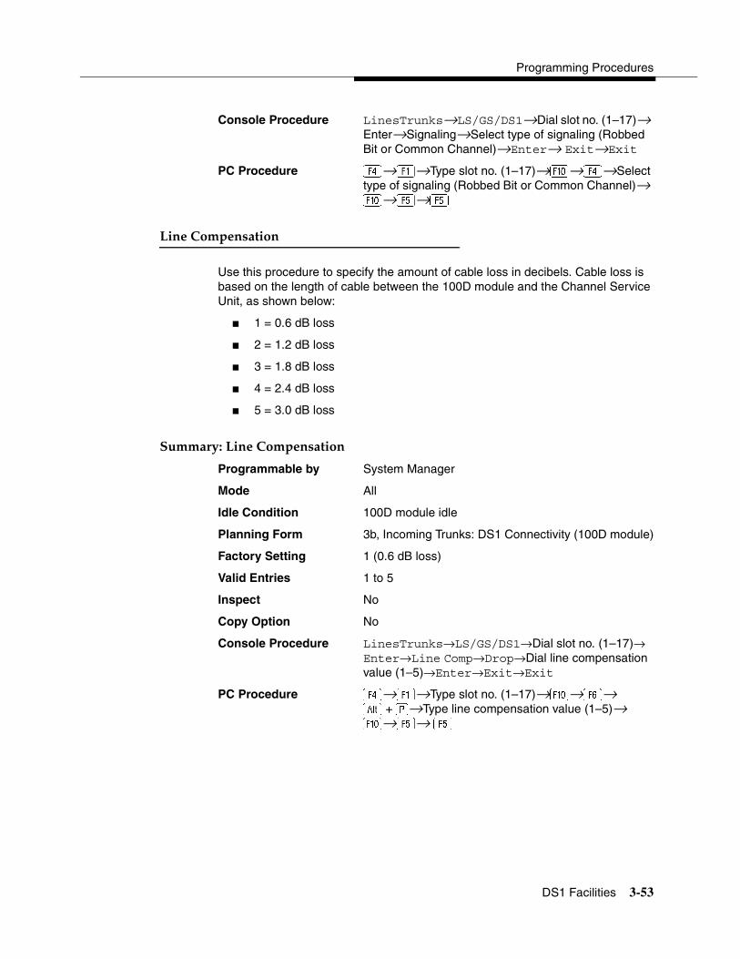
Programming Procedures
DS1 Facilities 3-53
Console Procedure LinesTrunks→LS/GS/DS1→Dial slot no. (1–17)→ Enter→Signaling→Select type of signaling (Robbed Bit or Common Channel)→Enter→ Exit→Exit
PC Procedure →�→Type slot no. (1–17)→�→→Select type of signaling (Robbed Bit or Common Channel)→ �→�→�
Line Compensation 3
Use this procedure to specify the amount of cable loss in decibels. Cable loss is based on the length of cable between the 100D module and the Channel Service Unit, as shown below:
� 1 = 0.6 dB loss
� 2 = 1.2 dB loss
� 3 = 1.8 dB loss
� 4 = 2.4 dB loss
� 5 = 3.0 dB loss
Summary: Line Compensation 3
Programmable by System Manager
Mode All
Idle Condition 100D module idle
Planning Form 3b, Incoming Trunks: DS1 Connectivity (100D module)
Factory Setting 1 (0.6 dB loss)
Valid Entries 1 to 5
Inspect No
Copy Option No
Console Procedure LinesTrunks→LS/GS/DS1→Dial slot no. (1–17)→Enter→Line Comp→Drop→Dial line compensation value (1–5)→Enter→Exit→Exit
PC Procedure →�→Type slot no. (1–17)→�→�→� +�→Type line compensation value (1–5)→ �→�→ �

System Programming
3-54 Tie Trunks
Channel Service Unit 3
Use this procedure to specify the type of equipment provided by the local telephone company as foreign exchange or special access.
NOTE:You do not need to use this procedure unless your system emulates loop-start or ground-start with the T1 type of DS1 facility.
Summary: Channel Service Unit 3
Programmable by System Manager
Mode All
Idle Condition 100D module idle
Planning Form 3b, Incoming Trunks: DS1 Connectivity (100D module)
Factory Setting Foreign Exchange
Valid Entries Foreign Exchange, Special Access
Inspect No
Copy Option No
Console Procedure LinesTrunks→LS/GS/DS1→Dial slot no. (1–17)→ Enter→ChannelUnit→Foreign Exchange or Special Access→Enter→Exit→Exit
PC Procedure →�→Type slot no. (1–17)→�→�→� or �→ �→�→�
Tie Trunks 3
This section covers programming procedures for the following tie trunk options:
� Direction
� Tie Trunk Seizure Type
� E&M Signal
� Dial Mode
� Tie Trunk Dial Tone
� Tie Trunk Answer Supervision Time
� Disconnect Time
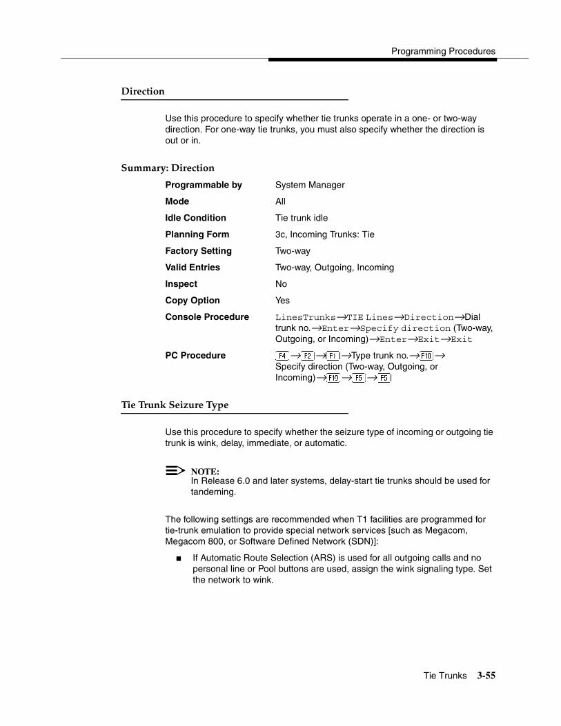
Programming Procedures
Tie Trunks 3-55
Direction 3
Use this procedure to specify whether tie trunks operate in a one- or two-way direction. For one-way tie trunks, you must also specify whether the direction is out or in.
Summary: Direction 3
Programmable by System Manager
Mode All
Idle Condition Tie trunk idle
Planning Form 3c, Incoming Trunks: Tie
Factory Setting Two-way
Valid Entries Two-way, Outgoing, Incoming
Inspect No
Copy Option Yes
Console Procedure LinesTrunks→TIE Lines→Direction→Dial trunk no.→Enter→Specify direction (Two-way, Outgoing, or Incoming)→Enter→Exit→Exit
PC Procedure →�→�→Type trunk no.→�→Specify direction (Two-way, Outgoing, or Incoming)→�→�→�
Tie Trunk Seizure Type 3
Use this procedure to specify whether the seizure type of incoming or outgoing tie trunk is wink, delay, immediate, or automatic.
NOTE:In Release 6.0 and later systems, delay-start tie trunks should be used for tandeming.
The following settings are recommended when T1 facilities are programmed for tie-trunk emulation to provide special network services [such as Megacom, Megacom 800, or Software Defined Network (SDN)]:
� If Automatic Route Selection (ARS) is used for all outgoing calls and no personal line or Pool buttons are used, assign the wink signaling type. Set the network to wink.

System Programming
3-56 Tie Trunks
� If personal line or Pool buttons (pool or dial-out codes) are used for outgoing calls, assign the immediate signaling type. Set the network to dial. Contact your service provider for more information about the dial setting.
� If Dialed Number Identification Service (DNIS) is used for incoming calls, assign the wink signaling type. The network is also set to wink. (Setting both ends to immediate also works.) Contact your service provider for more information about the appropriate setting.
� When DNIS is not used for incoming calls, assign the automatic signaling type. The network is set to automatic.
Summary: Tie Trunk Seizure Type 3
Programmable by System Manager
Mode All
Idle Condition Tie trunk idle
Planning Form 3c, Incoming Trunks: Tie
Factory Setting Wink
Valid Entries Wink, Delay, Immediate, Automatic
Inspect No
Copy Option Yes
Console Procedure LinesTrunks→TIE Lines→Intype orOuttype →Dial trunk no.→Enter→Specify seizure type (Wink, Delay, Immediate, or Automatic)→Enter→Exit→Exit
PC Procedure →�→� or→Type trunk no.→�→Specify seizure type (Wink, Delay, Immediate, or Automatic)→�→�→�
E&M Signal 3
Use this procedure to specify the type of tie trunk signal, as follows:
� E&M Mode:
— 1S, Type 1 Standard. Tie trunks that are connected through the local telephone company.
— 1C, Type 1 Compatible. Tie trunks that are connected directly to a system that uses 1S signaling.

Programming Procedures
Tie Trunks 3-57
� Simplex Mode:
— 5, Type 5 Simplex. Tie trunks that are connected to a system using Type 5 signaling.
NOTE:In Release 6.0 and later systems, E&M trunks that are used for private networking should be programmed at each end with a switch identifier that indicates the remote system where the trunk is connected. See ‘‘Uniform Dial Plan Facilities’’ on page 3-42 for details.
Summary: E&M Signal 3
Programmable by System Manager
Mode All
Idle Condition Tie trunk idle
Planning Form 3c, Incoming Trunks: Tie
Factory Setting 1S
Valid Entries 1S, 1C, 5
Inspect No
Copy Option Yes
Console Procedure LinesTrunks→TIE Lines→E&M Signal→Dial trunk no.→ Enter→Specify signaling type (1S, 1C, or 5)→ Enter→Exit→Exit
PC Procedure →�→→Type trunk no.→�→Specify signaling type (1S, 1C, or 5)→�→ �→�
Dial Mode 3
Use this procedure to specify whether an incoming or outgoing tie trunk is touch-tone or rotary.
Touch-tone cannot be programmed for incoming immediate signaling tie trunks. Users of touch-tone single-line telephones cannot make calls by using individual trunks programmed for rotary operation. The touch-tone signals generated from the telephone while the user is dialing are transmitted to the central office at the same time the rotary signals are sent to the system. The central office receives both signals and cannot process the call.

System Programming
3-58 Tie Trunks
Summary: Dial Mode 3
Programmable by System Manager
Mode All
Idle Condition Not required
Planning Form 3c, Incoming Trunks: Tie
Factory Setting Rotary
Valid Entries Rotary, Touch-tone
Inspect Yes
Copy Option Yes
Console Procedure To program a single line/trunk:LinesTrunks→TIE Lines→Inmode or Outmode→Entry Mode→Dial line/trunk no.→ Enter or Delete→Exit→Exit→Exit
To program a block of lines/trunks:LinesTrunks→TIE Lines→Inmode or Outmode→Select block of lines→Toggle LED on/off→Exit→Exit→Exit
PC Procedure To program a single line/trunk:→�→� or �→�→Type line/trunk no.→� or �→�→�→�
To program a block of lines/trunks:→�→� or �→Select block of lines→Toggle letter G on/off→�→�→�
Tie Trunk Dial Tone 3
Use this procedure to specify whether the system provides dial tone for people calling in on a tie trunk. The settings are remote (system provides dial tone) and local (system does not provide dial tone).
Summary: Tie Trunk Dial Tone 3
Programmable by System Manager
Mode All
Idle Condition Not required
Planning Form 3c, Incoming Trunks: Tie
Factory Setting Remote
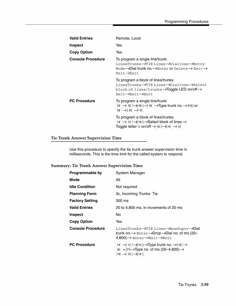
Programming Procedures
Tie Trunks 3-59
Valid Entries Remote, Local
Inspect Yes
Copy Option Yes
Console Procedure To program a single line/trunk:LinesTrunks→TIE Lines→Dialtone→Entry Mode→Dial trunk no.→Enter or Delete→ Exit→ Exit→Exit
To program a block of lines/trunks:LinesTrunks→TIE Lines→Dialtone→Select block of lines/trunks→Toggle LED on/off→ Exit→Exit→Exit
PC Procedure To program a single line/trunk:→�→�→�→Type trunk no.→� or �→ �→�
To program a block of lines/trunks:→�→�→Select block of lines→Toggle letter G on/off→�→�→�
Tie Trunk Answer Supervision Time 3
Use this procedure to specify the tie trunk answer supervision time in milliseconds. This is the time limit for the called system to respond.
Summary: Tie Trunk Answer Supervision Time 3
Programmable by System Manager
Mode All
Idle Condition Not required
Planning Form 3c, Incoming Trunks: Tie
Factory Setting 300 ms
Valid Entries 20 to 4,800 ms, in increments of 20 ms
Inspect No
Copy Option Yes
Console Procedure LinesTrunks→TIE Lines→AnsSupvr→Dial trunk no.→ Enter→Drop→Dial no. of ms (20–4,800)→ Enter→Exit→Exit
PC Procedure →�→�→Type trunk no.→�→� +�→Type no. of ms (20–4,800)→ �→�→�

System Programming
3-60 Tie Trunks
Disconnect Time 3
Use this procedure to specify the tie trunk disconnect time limit in milliseconds.
Summary: Disconnect Time 3
Programmable by System Manager
Mode All
Idle Condition Not required
Planning Form 3c, Incoming Trunks: Tie
Factory Setting 300 ms
Valid Entries 140 to 2,400 ms
Inspect No
Copy Option Yes
Console Procedure LinesTrunks→TIE Lines→Disconnect→Dial trunk no.→Enter→Drop→Dial no. of ms (140–2,400)→Enter→Exit→Exit
PC Procedure →�→�→Type trunk no.→�→� +�→Type no. of ms (140–2,400)→�→ �→�
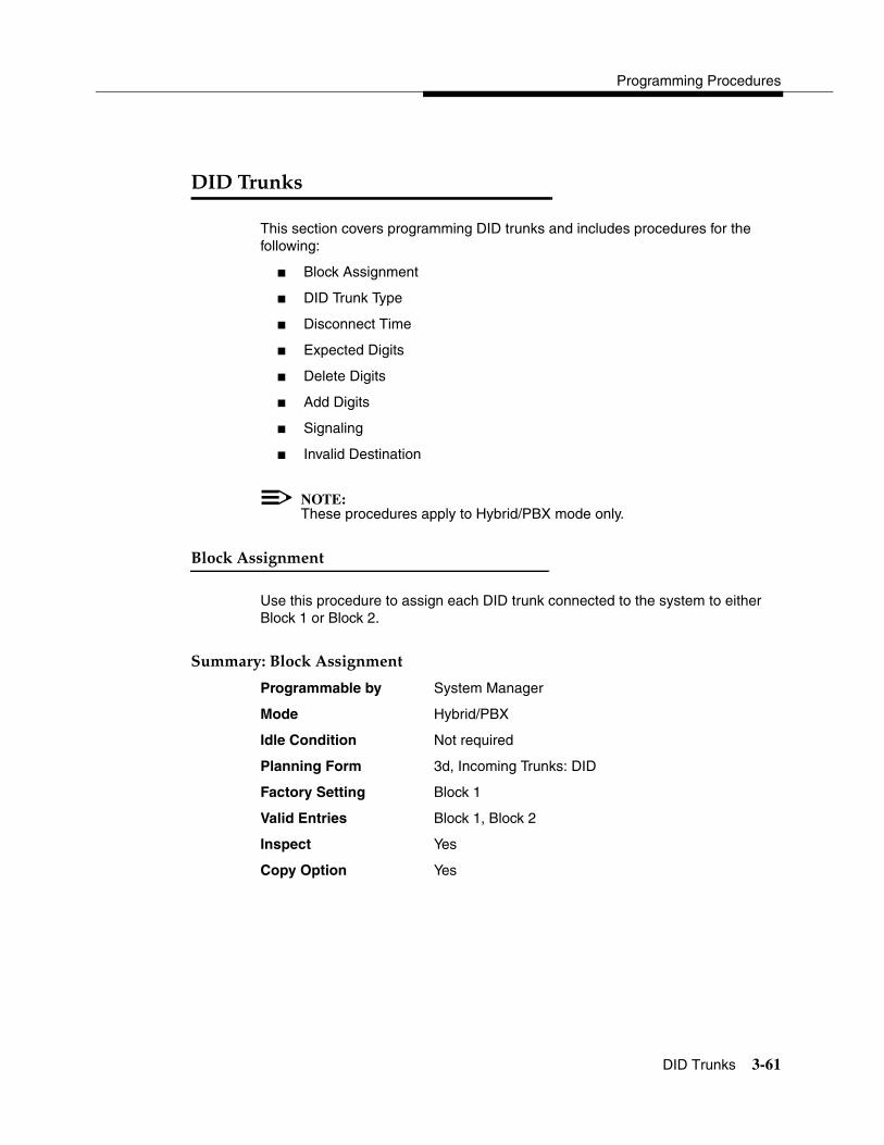
Programming Procedures
DID Trunks 3-61
3Programming Procedures
��������� 3
This section covers programming DID trunks and includes procedures for the following:
� Block Assignment
� DID Trunk Type
� Disconnect Time
� Expected Digits
� Delete Digits
� Add Digits
� Signaling
� Invalid Destination
NOTE:These procedures apply to Hybrid/PBX mode only.
�� ���������� 3
Use this procedure to assign each DID trunk connected to the system to either Block 1 or Block 2.
����������� ���������� 3
Programmable by System Manager
Mode Hybrid/PBX
Idle Condition Not required
Planning Form 3d, Incoming Trunks: DID
Factory Setting Block 1
Valid Entries Block 1, Block 2
Inspect Yes
Copy Option Yes
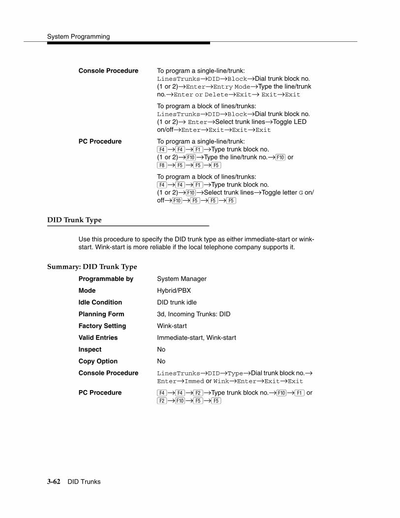
System Programming
3-62 DID Trunks
Console Procedure To program a single-line/trunk:LinesTrunks→DID→Block→Dial trunk block no. (1 or 2)→Enter→Entry Mode→Type the line/trunk no.→Enter or Delete→Exit→ Exit→Exit
To program a block of lines/trunks:LinesTrunks→DID→Block→Dial trunk block no. (1 or 2)→ Enter→Select trunk lines→Toggle LED on/off→Enter→Exit→Exit→Exit
PC Procedure To program a single-line/trunk:�→�→�→Type trunk block no.(1 or 2)→�→Type the line/trunk no.→� or �→�→�→�
To program a block of lines/trunks:�→�→�→Type trunk block no. (1 or 2)→�→Select trunk lines→Toggle letter G on/off→�→�→�→�
�������������� 3
Use this procedure to specify the DID trunk type as either immediate-start or wink-start. Wink-start is more reliable if the local telephone company supports it.
����������������������� 3
Programmable by System Manager
Mode Hybrid/PBX
Idle Condition DID trunk idle
Planning Form 3d, Incoming Trunks: DID
Factory Setting Wink-start
Valid Entries Immediate-start, Wink-start
Inspect No
Copy Option No
Console Procedure LinesTrunks→DID→Type→Dial trunk block no.→ Enter→Immed or Wink→Enter→Exit→Exit
PC Procedure �→�→�→Type trunk block no.→�→��or �→�→�→�

Programming Procedures
DID Trunks 3-63
�� ���� ������ 3
Use this procedure to specify the DID trunk disconnect time limit in milliseconds.
����������� ���� ������ 3
Programmable by System Manager
Mode Hybrid/PBX
Idle Condition Not required
Planning Form 3d, Incoming Trunks: DID
Factory Setting 500 ms
Valid Entries 10 to 2,400 ms, in increments of 10 ms
Inspect No
Copy Option Yes
Console Procedure LinesTrunks→DID→Disconnect→Dial trunk no.→ Enter→Drop→Dial no. of ms (10–2,400)→ Enter→Exit→ Exit
PC Procedure �→�→�→Type trunk no.→�→ + �→Type no. of ms (10–2,400)→��→�→�
���� ��������� 3
Use this procedure to tell the system how many digits are sent by the local telephone company.
NOTE:In Release 6.0 and later systems, if the dialed digits received on a DID trunk correspond to a non-local extension number, the call is routed to that extension.
! SECURITY ALERT:In Release 6.0 and later systems, do not assign a non-local remote ARS code to the non-local dial plan. Doing so would allow DID callers to use the private network to make outside calls. For more information, see ‘‘Uniform Dial Plan Routing’’ on page 3-208.

System Programming
3-64 DID Trunks
������������� ��������� 3
Programmable by System Manager
Mode Hybrid/PBX
Idle Condition Not required
Planning Form 3d, Incoming Trunks: DID
Factory Setting 3 digits
Valid Entries 1 to 4 digits
Inspect No
Copy Option No
Console Procedure LinesTrunks→DID→ExpectDigit→Dial trunk block no. (1 or 2)→Enter→Drop→Dial no. of digits (1–4)→Enter→Exit→Exit
PC Procedure �→�→�→Type trunk block no. (1 or 2)→ �→�+ �→Type no. of digits (1–4) �→ �→�
������������ 3
Use this procedure to specify the number of leading digits to be deleted from the digits sent by the local telephone company. Use this procedure when the number of digits sent by the telephone company is greater than the number in the system numbering plan.
��������������������� 3
Programmable by System Manager
Mode Hybrid/PBX
Idle Condition Not required
Planning Form 3d, Incoming Trunks: DID
Factory Setting 0 digits
Valid Entries 0 to 4 digits
Inspect No
Copy Option No
Console Procedure LinesTrunks→DID→DeleteDigit→Dial trunk block no. (1 or 2)→Enter→Drop→Dial no. of digits (0–4)→Enter→Exit→Exit
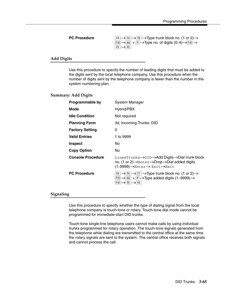
Programming Procedures
DID Trunks 3-65
PC Procedure �→�→→Type trunk block no. (1 or 2)→ �→ + �→Type no. of digits (0–4)→�→ �→�
��������� 3
Use this procedure to specify the number of leading digits that must be added to the digits sent by the local telephone company. Use this procedure when the number of digits sent by the telephone company is fewer than the number in the system numbering plan.
������������������ 3
Programmable by System Manager
Mode Hybrid/PBX
Idle Condition Not required
Planning Form 3d, Incoming Trunks: DID
Factory Setting 0
Valid Entries 1 to 9999
Inspect No
Copy Option No
Console Procedure LinesTrunks→DID→Add Digits→Dial trunk block no. (1 or 2)→Enter→Drop→Dial added digits (1–9999)→Enter→ Exit→Exit
PC Procedure �→�→�→Type trunk block no. (1 or 2)→ �→ +��→Type added digits (1–9999)→�→�→�
��������� 3
Use this procedure to specify whether the type of dialing signal from the local telephone company is touch-tone or rotary. Touch-tone dial mode cannot be programmed for immediate-start DID trunks.
Touch-tone single-line telephone users cannot make calls by using individual trunks programmed for rotary operation. The touch-tone signals generated from the telephone while dialing are transmitted to the central office at the same time the rotary signals are sent to the system. The central office receives both signals and cannot process the call.
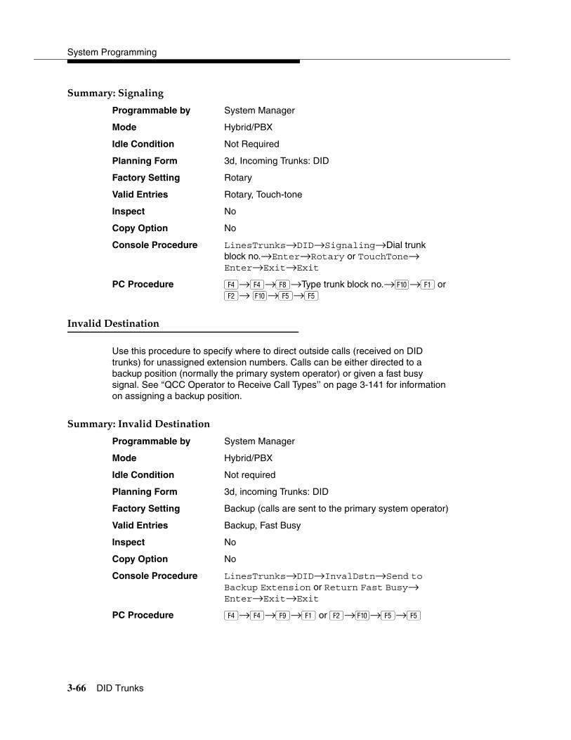
System Programming
3-66 DID Trunks
������������������ 3
Programmable by System Manager
Mode Hybrid/PBX
Idle Condition Not Required
Planning Form 3d, Incoming Trunks: DID
Factory Setting Rotary
Valid Entries Rotary, Touch-tone
Inspect No
Copy Option No
Console Procedure LinesTrunks→DID→Signaling→Dial trunk block no.→Enter→Rotary or TouchTone→Enter→Exit→Exit
PC Procedure �→�→�→Type trunk block no.→�→� or �→ �→�→�
������������������ 3
Use this procedure to specify where to direct outside calls (received on DID trunks) for unassigned extension numbers. Calls can be either directed to a backup position (normally the primary system operator) or given a fast busy signal. See ‘‘QCC Operator to Receive Call Types’’ on page 3-141 for information on assigning a backup position.
��������������������������� 3
Programmable by System Manager
Mode Hybrid/PBX
Idle Condition Not required
Planning Form 3d, incoming Trunks: DID
Factory Setting Backup (calls are sent to the primary system operator)
Valid Entries Backup, Fast Busy
Inspect No
Copy Option No
Console Procedure LinesTrunks→DID→InvalDstn→Send to Backup Extension or Return Fast Busy→ Enter→Exit→Exit
PC Procedure �→�→�→� or �→�→�→�
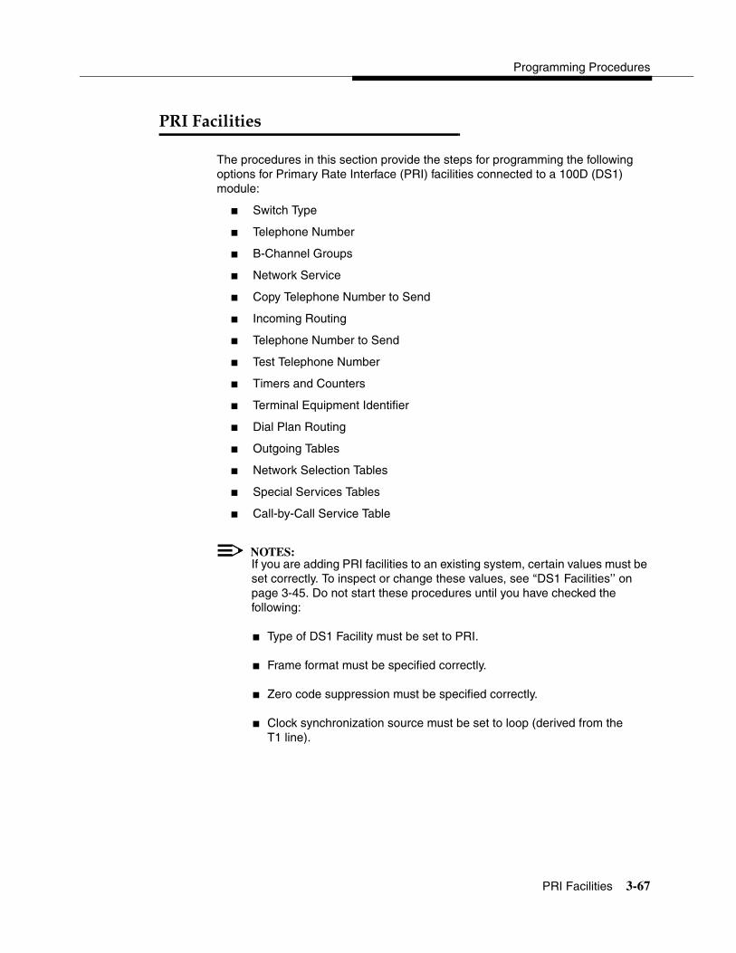
Programming Procedures
PRI Facilities 3-67
������ ������ 3
The procedures in this section provide the steps for programming the following options for Primary Rate Interface (PRI) facilities connected to a 100D (DS1) module:
� Switch Type
� Telephone Number
� B-Channel Groups
� Network Service
� Copy Telephone Number to Send
� Incoming Routing
� Telephone Number to Send
� Test Telephone Number
� Timers and Counters
� Terminal Equipment Identifier
� Dial Plan Routing
� Outgoing Tables
� Network Selection Tables
� Special Services Tables
� Call-by-Call Service Table
NOTES:If you are adding PRI facilities to an existing system, certain values must be set correctly. To inspect or change these values, see ‘‘DS1 Facilities’’ on page 3-45. Do not start these procedures until you have checked the following:
� Type of DS1 Facility must be set to PRI.
� Frame format must be specified correctly.
� Zero code suppression must be specified correctly.
� Clock synchronization source must be set to loop (derived from the T1 line).

System Programming
3-68 PRI Facilities
The settings for frame format and zero code suppression must be consistent with the options selected when the PRI connection was ordered.
If you are using ARS in connection with PRI, make sure you select voice, data, or voice and data, as appropriate, when you perform the ARS ‘‘Voice and/or Data Routing’’ on page 3-208.
� �� !����� 3
In Release 4.2 and later systems, use this procedure to specify the PRI connection through the following switch types:
� 4ESS
� 5ESS
� Nortel DMS-100 BCS 36 for local exchange carrier services
� Nortel DMS-250 serving the MCI network
� Digital Switch Corporation DEX600E serving the MCI network
In Release 6.0 and later systems, two additional switch types allow you to specify additional switch options in order to set up a PRI tandem trunk that connects two MERLIN LEGEND Communications Systems or a MERLIN LEGEND Communications System and a DEFINITY Communications System. The two additional options are the following:
� Legend-NTWK
� Legend-PBX
To set up a PRI tandem trunk, one system is specified as operating in PBX mode and the other as operating in network mode. When you program this switch type, you specify the type of switch at the other end of the PRI trunk, not the local switch. The slot number that you enter is the slot number on the local system.
The following rules apply to PRI tandem trunks in PBX or network mode:
� A single unused B-channel group number is automatically assigned to all 23 B-channels on the trunk; B-channels may be removed or added (for more information, see ‘‘B-Channel Groups’’ on page 3-70). The group can still exist, even if it includes no B-channels.
� PRI Dial Plan Routing does not apply for incoming calls on the trunk. Incoming routing is automatically set to Route Directly to UDP for B-channels in the automatically assigned group; this cannot be changed as long as the Legend-PBX or Legend-NTWK switch type is in effect (see ‘‘Incoming Routing’’ on page 3-74). However, local extensions need not be included in the UDP Routing table.
Programming Procedures
PRI Facilities 3-69
� PRI outgoing tables do not apply to outgoing calls on the trunk.
� The system automatically assigns Electronic Tandem Network (ETN) as the network service for the B-channel group that is automatically assigned to the PRI tandem trunk; this setting cannot be changed as long as the switch type is in effect (see ‘‘Network Service’’ on page 3-72).
� The Copy Telephone Number to Send setting is set to Do Not Copy for the PRI tandem trunk B-channel group; this setting cannot be changed as long as the switch type is in effect (see ‘‘Copy Telephone Number to Send’’ on page 3-73).
���������� �� !����� 3
Programmable by System Manager
Mode Hybrid/PBX
Idle Condition Not required
Planning Form 3b, Incoming Trunks: DS1 Connectivity (100D module)
Factory Setting 4ESS
Valid Entries Not applicable
Inspect Yes
Copy Option No
Console Procedure LinesTrunks→PRI→SwitchType→Dial slot no. (1–17)→Enter→Specify switch type→Enter→ Exit→Exit
PC Procedure �→→�→Type slot no. (1–17)→�→Specify switch type→�→�→�
�����!����"��#�� 3
Use this procedure to assign a string of up to 12 digits to each PRI channel. This string must match the number sent by the network (that is, the number provided by the PRI service provider) to indicate the number dialed by an outside caller. The system uses this number to route the call to the correct destination, which means that the number assigned to each channel in the same B-channel group must be unique. Note also that the number cannot be the same as the associated test telephone number.

System Programming
3-70 PRI Facilities
��������������!����"��#�� 3
Programmable by System Manager
Mode Hybrid/PBX, Key
Idle Condition Not required
Planning Form 3b, Incoming Trunks: DS1 Connectivity (100D module)
Factory Setting No digits
Valid Entries Up to 12 digits (any combination of 0 to 9)
Inspect No
Copy Option No
Console Procedure LinesTrunks→PRI→PhoneNumber→Dial trunk no.→Enter→Drop→Dial telephone no. (up to 12 digits; 0–9)→Enter→ Exit→Exit
PC Procedure �→→�→Type trunk no.→�→ +��→Type telephone no. (up to 12 digits; 0–9)→�→�→�
$%!������&���� 3
Use this procedure to perform the following:
� Assign B-channels to a group.
� Associate individual ISDN channels (that can place and receive calls) on the B-channels in each group.
B-channels are partitioned into trunk groups when PRI service is ordered. The trunk groups defined when service is ordered must match the B-channel groups defined when the MERLIN LEGEND Communications System is programmed.
NOTE:In Release 6.0 and later systems, when the PRI switch type is set to Legend-PBX or Legend-NTWK, all B-channels for a PRI tandem trunk are automatically assigned to a single unused B-channel group. If your private network includes drop-and-insert hardware between the networked switches, use this procedure to remove a dropped B-channel from the group, after the switch type has been programmed and the B-channels automatically assigned. This equipment must never drop channel 24, which provides necessary signalling for the B-channels.
Programming Procedures
PRI Facilities 3-71
Each B-channel can be assigned to only one group, and each ISDN channel can be associated with only one group. Up to 80 B-channel groups can be established.
Each group can contain up to 23 channels; however, all channels assigned must signal through the same D-channel (that is, must be connected to the same 100D module).
! CAUTION:B-channels must be assigned in the order of system search (through the group) for an available channel. To minimize call attempts on the same line or trunk, you must arrange B-channels in the opposite order of the hunting arrangement provided by the network service provider.
B-channels must be identified by control unit slot and port numbers since they are not associated with a line/trunk number or a logical ID.
PRI B-channel groups programmed for line routing perform similarly to loop-start trunks. PRI B-channel groups programmed for dial plan routing perform similarly to DID trunks.
NOTE:If more lines than B-channels are assigned to a B-channel group, users may experience situations where a line that is idle is not able to seize a B-channel. The user receives a fast busy tone.
���������$%!������&���� 3
Programmable by System Manager
Mode Hybrid/PBX, Key
Idle Condition Not required
Planning Form 3b, Incoming Trunks: DS1 Connectivity (100D module)
Factory Setting Not applicable
Valid Entries Group numbers (1 to 80)
Inspect Yes
Copy Option No
Console Procedure To program a single-line/trunk:LinesTrunks→PRI→B-ChannlGrp→B Channels→Dial group no. (1–80)→Enter→Dial B-channel slot and port nos.→Enter→Lines→Dial group no.→Enter→Entry Mode→Dial line/trunk no.→Enter→Exit→Exit→Exit
System Programming
3-72 PRI Facilities
To program a block of lines/trunks:LinesTrunks→PRI→B-ChannlGrp→B Channels→Dial group no. (1–80)→Enter→Dial B-channel slot and port no.→ Enter→Lines→Dial group no.→Enter→Select specific lines/trunks→Toggle LED on/off→Exit→Exit→Exit
PC Procedure To program a single-line/trunk:�→→�→�→Type group no.→Type B-channel slot and port nos.→�→Type group no.→�→→Type line/trunk no.→��→ �→�→�
To program a block of lines/trunks:�→→�→�→Type group no.→Type B-channel slot and port nos.→�→Type group no.→�→Select specific lines/trunks→Toggle letter G on or off→�→�→�
"�� ��������� � 3
Use this procedure to specify the type of outgoing service provided by eachB-channel group.
� You can enter a service not shown on the Network Service screen by using the 5-digit binary code that represents the service in the Network Facilities Information Element of ISDN PRI signaling protocol. For information on these codes, contact your service provider.
� In Release 6.0 and later systems, setting the switch type to Legend-PBX or Legend-NTWK automatically assigns the B-channels for the specified PRI tandem trunk to a single unused B-channel group. This group is automatically assigned LEGEND UDP as the general type of network service and Electronic Tandem Network (ETN) as specific LEGEND UDP network service. As long as the switch type for the PRI trunk remains as Legend-PBX or Legend-NTWK, you cannot change the type of network service. For more information about switch types, see ‘‘Switch Type’’ on page 3-68.
Programming Procedures
PRI Facilities 3-73
���������"�� ��������� � 3
Programmable by System Manager
Mode Hybrid/PBX, Key
Idle Condition Not required
Planning Form 3b, Incoming Trunks: DS1 Connectivity (100D module)
Factory Setting Not applicable
Valid Entries AT&T Toll, 5ESS Local, MCI Toll, Miscellaneous,DMS-100 Local, LEGEND UDP
Inspect Yes
Copy Option No
Console Procedure LinesTrunks→PRI→B-ChannlGrp→ NetworkServ→Dial group no.→Enter→Specify network service (AT&T Toll, 5ESS Local, MCI Toll, Miscellaneous, DMS-100, Local, Legend UDP)→ Enter→Exit→Exit→Exit→ Exit
PC Procedure �→→�→�→Type group no.→�→Specify network service (AT&T Toll, 5ESS Local, MCI Toll, Miscellaneous, DMS-100, Local, Legend UDP)→�→�→�→�→�
%���������!����"��#���������� 3
Use this procedure to indicate whether or not the telephone number to send to the network (for calls going out over ISDN lines assigned to a B-channel group) is copied from the number assigned to that channel.
NOTE:In Release 6.0 and later systems (Hybrid/PBX mode only), setting the switch type to Legend-PBX or Legend-Ntwk automatically assigns Copy Number as the option for the single B-channel group associated with PRI tandem trunk that you specified in the Switch Type setting. As long as the switch type for the slot is set this way, you cannot change the Copy programming. For more information about switch types, see ‘‘Switch Type’’ on page 3-68.
Select Do Not Copy Telephone Number either when a telephone number to send is assigned to each channel in the B-channel group or when no telephone number is to be sent to the network. In the latter case, make sure that no telephone
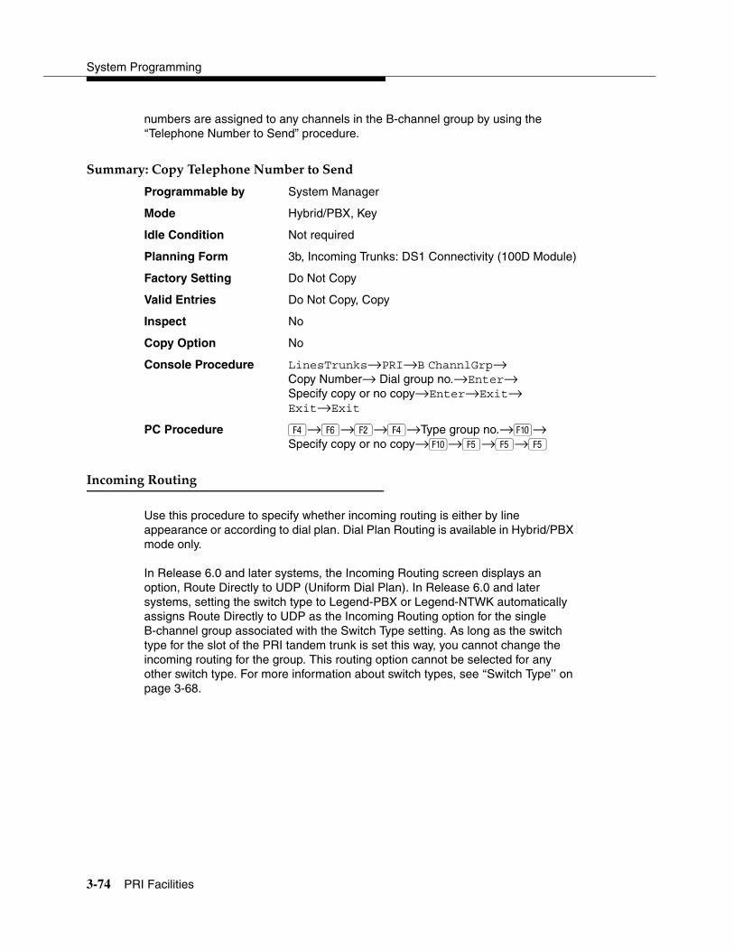
System Programming
3-74 PRI Facilities
numbers are assigned to any channels in the B-channel group by using the ‘‘Telephone Number to Send” procedure.
���������%���������!����"��#���������� 3
Programmable by System Manager
Mode Hybrid/PBX, Key
Idle Condition Not required
Planning Form 3b, Incoming Trunks: DS1 Connectivity (100D Module)
Factory Setting Do Not Copy
Valid Entries Do Not Copy, Copy
Inspect No
Copy Option No
Console Procedure LinesTrunks→PRI→B ChannlGrp→Copy Number→ Dial group no.→Enter→Specify copy or no copy→Enter→Exit→Exit→Exit
PC Procedure �→→�→�→Type group no.→�→ Specify copy or no copy→�→�→�→�
�� ������������� 3
Use this procedure to specify whether incoming routing is either by line appearance or according to dial plan. Dial Plan Routing is available in Hybrid/PBX mode only.
In Release 6.0 and later systems, the Incoming Routing screen displays an option, Route Directly to UDP (Uniform Dial Plan). In Release 6.0 and later systems, setting the switch type to Legend-PBX or Legend-NTWK automatically assigns Route Directly to UDP as the Incoming Routing option for the single B-channel group associated with the Switch Type setting. As long as the switch type for the slot of the PRI tandem trunk is set this way, you cannot change the incoming routing for the group. This routing option cannot be selected for any other switch type. For more information about switch types, see ‘‘Switch Type’’ on page 3-68.

Programming Procedures
PRI Facilities 3-75
����������� ������������� 3
Programmable by System Manager
Mode Line appearance: Hybrid/PBX, Key; Dial Plan Routing or Route Directly to UDP; Hybrid/PBX only
Idle Condition Not required
Planning Form 3b, Incoming Trunks: DS1 Connectivity (100D module)
Factory Setting Line appearance
Valid Entries Dial Plan Routing, Routing by Line Appearance, Route Directly to UDP
Inspect No
Copy Option No
Console Procedure LinesTrunks→PRI→B-ChannlGrp→Incoming Rtg→ Dial B-channel group no.→ Enter→Specify routing method (Dial Plan Routing, Routing by Line Appearance, or Route Directly to UDP)→Enter→Exit→ Exit→Exit
PC Procedure �→→�→→Type B-channel group no.→ �→Specify routing method (Dial Plan Routing, Routing by Line Appearance, or Route Directly to UDP)→ �→�→�→�
�����!����"��#���������� 3
Use this procedure to assign the telephone number to send to the network when outgoing calls are made on an ISDN line. If the person being called subscribes to an automatic number identification service, the number indicates who is calling.
The number assigned to each channel does not have to be unique because it is not used for routing.
The telephone number sent to the network can be one of the following:
� The extension number assigned to the calling telephone (Select Extension Only in Step 4).
� The extension number substituted into the lower order digits of a systemwide base number (Select Base Number with Ext in Step 4).
� The facility-based line telephone number (Select Line Telephone Number in Step 4).

System Programming
3-76 PRI Facilities
NOTE:Only one base number is supported per system. In systems having non-uniform extension numbers, for example, where there are some 3-digit extension numbers and some 4-digit extension numbers, one base number may not be sufficient to represent all the outside telephone numbers of all extensions.
��������������!����"��#���������� 3
Programmable by System Manager
Mode All
Idle Condition Not required
Planning Form 3b, Incoming Trunks: DS1 Connectivity (100D module)
Factory Setting No digits are assigned
Valid Entries Up to 12 digits (any combination of 0 to 9)
Inspect No
Copy Option No
Console Procedure LinesTrunks→PRI→NumbrToSend→Specify type of no.→Enter→Drop→Dial base no.→Enter→ Dial line no.→Enter→Drop→Dial telephone no. (up to 12 digits; 0–9)→Enter→Exit→Exit
PC Procedure �→→�→Specify type of no.→�→ + �→Type base no.→�→ + �→Type telephone no. (up to 12 digits; 0–9)→ �→�→�
���������!����"��#�� 3
Use this procedure to assign a test line or trunk telephone number for each 100D module installed in the control unit.
The number assigned to the test line/trunk must be different from the numbers assigned to other channels in the same B-channel group. It must be identical to the number provided by the PRI service provider.
������������������!����"��#�� 3
Programmable by System Manager
Mode Hybrid/PBX, Key
Idle Condition Not required
Planning Form 3b, Incoming Trunks: DS1 Connectivity (100D module)

Programming Procedures
PRI Facilities 3-77
Factory Setting Not applicable
Valid Entries Telephone number of up to 12 digits
Inspect No
Copy Option No
Console Procedure LinesTrunks→PRI→Test TelNum→Dial slot no. (1–17)→Enter→Drop→Dial telephone no. (up to 12 digits; 0–9)→ Enter→Exit→Exit
PC Procedure �→→�→Type slot no. (1–17)→�→ + �→ Type telephone no. (up to 12 digits; 0–9)→�→�→�
����������%������ 3
Use this procedure to set timer and counter thresholds.
! CAUTION:The factory settings for these thresholds are standard and rarely need to be changed. If you are not sure of the correct timer and threshold settings for your PRI lines and trunks, check with your Lucent Technologies representative before you make a change. Incorrect settings can cause your PRI lines and trunks to malfunction.
If the network does not respond before the programmed time or count, the system takes the appropriate corrective action.
The timers and counters are listed below.
� T200 Timer. Times the delay in the link layer acknowledgment of a message sent from the system to the network over a D-channel.
� T203 Timer. Times the interval between each exchange of messages between the system and the network on the D-channel.
� N200 Counter. Counts the number of times the system has transmitted a message on a D-channel because no link layer acknowledgment is received from the network.
� N201 Counter. Counts the maximum number of layer three octets the system can send or receive in a single D-channel message.
� K Counter. Counts the number of layer three unacknowledged messages sent from the system to the network on a D-channel.
� T303 Timer. Times the delay in network response when the system sends a setup message to initiate an outgoing call.
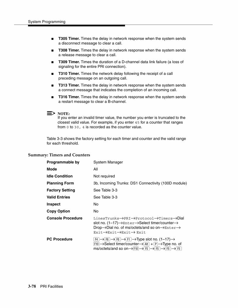
System Programming
3-78 PRI Facilities
� T305 Timer. Times the delay in network response when the system sends a disconnect message to clear a call.
� T308 Timer. Times the delay in network response when the system sends a release message to clear a call.
� T309 Timer. Times the duration of a D-channel data link failure (a loss of signaling for the entire PRI connection).
� T310 Timer. Times the network delay following the receipt of a call preceding message on an outgoing call.
� T313 Timer. Times the delay in network response when the system sends a connect message that indicates the completion of an incoming call.
� T316 Timer. Times the delay in network response when the system sends a restart message to clear a B-channel.
NOTE:If you enter an invalid timer value, the number you enter is truncated to the closest valid value. For example, if you enter 45 for a counter that ranges from 0 to 30, 4 is recorded as the counter value.
Table 3-3 shows the factory setting for each timer and counter and the valid range for each threshold.
�������������������%������ 3
Programmable by System Manager
Mode All
Idle Condition Not required
Planning Form 3b, Incoming Trunks: DS1 Connectivity (100D module)
Factory Setting See Table 3-3
Valid Entries See Table 3-3
Inspect No
Copy Option No
Console Procedure LinesTrunks→PRI→Protocol→Timers→Dial slot no. (1–17)→Enter→Select timer/counter→Drop→Dial no. of ms/octets/and so on→Enter→Exit→Exit→Exit→ Exit
PC Procedure �→→→�→Type slot no. (1–17)→ �→Select timer/counter→ +��→Type no. of ms/octets/and so on→�→�→�→�→�

Programming Procedures
PRI Facilities 3-79
����������'��������������(��� 3
Use this procedure to assign the link layer address of a piece of equipment connected to each D-channel. Normally, only one piece is connected and the system assumes that the Terminal Equipment Identifier (TEI) is 0.
! CAUTION:The value of the TEI rarely has to be changed. Check with your Lucent Technologies representative before changing this value.
�������������������'��������������(��� 3
Programmable by System Manager
Mode All
Idle Condition Not required
Planning Form 3b, Incoming Trunks: DS1 Connectivity (100D module)
Factory Setting 0
Valid Entries 0 to 63
Table 3-3. Timers and Counters
Timer/Counter Purpose Factory Setting Valid Range
T200 Timer Maximum response time 1 second 1,000 to 3,000 ms
T203 Timer Maximum time 30 seconds 1 to 60 seconds
N200 Counter Maximum transmissions 3 transmissions 1 to 5 transmissions
N201 Counter Maximum octets 260 octets 16 to 260 octets
K Counter Maximum outstanding
I-frames
7 frames 1 to 15 frames
T303 Timer Set up timeout 4 seconds 4 to 12 seconds
T305 Timer Disconnect timeout 4 seconds 4 to 30 seconds
T308 Timer Release timeout 4 seconds 4 to 12 seconds
T309 Timer Signal loss 90 seconds 30 to 120 seconds
T310 Timer Call Proc. timeout 60 seconds 2 to 120 seconds
T313 Timer Connect timeout 4 seconds 4 to 60 seconds
T316 Timer Restart timeout 120 seconds 30 to 120 seconds

System Programming
3-80 PRI Facilities
Inspect No
Copy Option No
Console Procedure LinesTrunks→PRI→Protocol→TEI→Dial slot no. (1–17)→Enter→Drop→Dial new ID no. (0–63)→ Enter→Exit→ Exit→Exit
PC Procedure �→→→�→Type slot no. (1–17)→�→ +��→Type new ID no. (0–63)→�→�→ �→�
����������������� 3
Dial plan routing provides a way to route incoming calls on a “per B-channel group” basis. An incoming call is routed by matching the incoming number (by service, number of digits, and pattern) and then optionally deleting and/or adding digits to direct the call to a specific endpoint. A service must be specified; the number of digits and pattern are optional. For example, you can specify that calls received from a particular area code should be routed to the specific individual or group responsible for accounts in that area.
Dial plan routing is available in Hybrid/PBX mode only. Key systems route incoming calls on a per-line basis.
In Release 4.2 and later, you can specify the following additional services:
� MCI Toll Services available for a DMS-250 or DEX600E switch type:
— MCI PRISM
— MCI Vnet
— MCI 800
— MCI 900
� Local exchange carrier services available for a DMS-100 switch type:
— DMS Private
— DMS INWATS
— DMS OUTWATS
— DMS FX (foreign exchange)
— DMS Tie Trunk

Programming Procedures
PRI Facilities 3-81
NOTES:� You can enter a service not shown on the Network Service screen by
using the 5-digit binary code that represents the service in the Network Facilities Information Element of ISDN PRI layer 3 signaling protocol. Contact your service provider for more information about the codes.
� Dial plan routing does not affect PRI tandem trunks connected to slots with switch types of LEGEND-Network or LEGEND-PBX. See ‘‘Switch Type’’ on page 3-68 for details.
� You must program a service before you program any other Dial Plan Routing function. If you have not programmed a service, complete the procedure below for the Service option and then repeat the procedure for each optional function that you want to program.
�������������������������� 3
Programmable by System Manager
Mode Hybrid/PBX
Idle Condition Not required
Planning Form 3b, Incoming Trunks: DS1 Connectivity (100D module)
Factory Setting Service: empty; Patterns: blank; Total Digits: 0;Delete Digits: 0; Add Digits: 0
Valid Entries Service: Toll, Local, MiscellaneousEntries: 0–15Digits per Pattern: 0–8Total Digits: 1–14Delete Digits: 0–14, 0=wildcardAdd Digits: 0–4 (valid digits: 0–9)
Inspect No
Copy Option No
Console Procedure To specify Service:LinesTrunks→PRI→DialPlanRtg→Service→Dial entry no.→Enter→Select service (AT&T Toll, 5ESS Local, MCI Toll, Miscellaneous, or DMS-100 Local)→Exit→ Exit→Exit
To specify Patterns:LinesTrunks→PRI→DialPlanRtg→Patterns→Dial entry no.→Enter→Drop→Dial pattern (0–8)→ Enter→Exit→Exit→Exit

System Programming
3-82 PRI Facilities
To specify Total Digits:LinesTrunks→PRI→DialPlanRtg→Total Digits→Dial entry no.→Enter→Drop→Dial digits (1–14)→Enter→Exit→ Exit→Exit
To specify Delete Digits:LinesTrunks→PRI→DialPlanRtg→Delete Digits→Dial entry no.→Enter→Drop→Dial delete digits (0–14; 0=wildcard)→Enter→ Exit→Exit→Exit
To specify Add Digits:LinesTrunks→PRI→DialPlanRtg→Add Digits→Dial entry no.→Enter→Drop→Dial add digits (0–14; valid digits: 0–9)→ Enter→Exit→Exit→Exit
PC Procedure To specify Service:�→→�→�→Type entry no.→�→ Select service (AT&T Toll, 5ESS Local, MCI Toll, Miscellaneous, or DMS-100 Local)→�→�→�→�
To specify Patterns:�→→�→� Type entry no.→�→ + �→Type pattern (0–8)→�→�→ �→�
To specify Total Digits:�→→�→�→Type entry no.→�→ + �→Type digits (1–14)→� →�→ �→�
To specify Delete Digits:�→→�→� Type entry no.→�→ + �→Type delete digits (0–14; 0=wildcard)→�→�→�→�
To specify Add Digits:�→→�→� Type entry no.→�→ +��→Type add digits (0–14; valid digits: 0–9)→�→�→�→�
Programming Procedures
PRI Facilities 3-83
)����������#�� 3
PRI provides tables that work in conjunction with personal lines, pools, and ARS tables to route calls. The following tables specify services for outgoing calls:
� Call-by-Call. Selects an outgoing service, based on routing digits and the bearer capability (voice, data, or both) of the calling extension. It allows a single group of B-channels to carry a variety of services, such as ACCUNET, SDN, and Megacom WATS.
� Network Selection. Selects a long-distance carrier. Calls that match Network Selection tables can be routed to a specific service by the Call-by-Call tables.
� Special Services. Selects services, such as international dialing and operator assistance. Calls that match these tables are not routed by the Call-by-Call tables.
NOTES:� PRI tables that work with pools and ARS apply to Hybrid/PBX mode
only.
� In Release 6.0 and later systems, when the PRI switch type is set for Legend-PBX or Legend-NTWK to support a PRI tandem trunk, outgoing tables do not affect outgoing calls for the PRI facility connected to the slot specified by the Switch Type setting.
"�� �������� �������#�� 3
Dialed prefixes for selecting long-distance carriers are matched to entries in the four Network Selection tables. Eight default tables are provided, specifying 10*** and 101****. The asterisks are wildcards that represent the various long-distance carrier codes. (10*** is the current U.S. standard for specifying long-distance carriers; 101**** is provided for future use.)
NOTES:� U.S. customers rarely need to program additional Network Selection
tables because long-distance carrier codes match 10*** or 101****.
� In Release 6.0 and later systems (Hybrid/PBX mode only), when routing private network trunks for ARS 10*** and 101**** (Interexchange or IXC) calls from a networked switch that is not connected to the public switched network and only has private trunks, the private network trunks must be assigned to the main pool on the switch where ARS is dialed. The ARS access code for local and remote systems must be identical. The following procedure does not affect these PRI tandem trunks.

System Programming
3-84 PRI Facilities
���������"�� �������� �������#�� 3
Programmable by System Manager
Mode Key and Hybrid/PBX
Idle Condition Not required
Planning Form 3b, Incoming Trunks: DS1Connectivity (100D module)
Factory Setting Not applicable
Valid Entries Prefix for long distance carrier
Inspect No
Copy Option No
Console Procedure LinesTrunks→PRI→OutgoingTbl→NetwkSelect→Dial entry no.→Enter→Drop→Dial prefix→Enter→ Exit→Exit→Exit
PC Procedure �→→�→�→Type entry no.→�→ + �→ Type prefix→�→�→�→�
��� ��������� ����#�� 3
Eight tables provide for international calling and for operator-assisted calls. Default tables include the special prefixes 0 and 00 for operator-assisted calls. Dialed numbers are matched against entries in these tables for patterns (011, 010, 01, 00, 0, and 1); for operator assistance (operator-assisted, presubscribed common carrier operator, and none); and for type of number (national or international). Up to four digits can be deleted.
������������ ��������� ����#�� 3
Programmable by System Manager
Mode Key and Hybrid/PBX
Idle Condition Not required
Planning Form 3b, Incoming Trunks: DS1 Connectivity (100D module)
Factory Setting See Table 3-4
Valid Entries Prefix for international or operator-assisted calls
Inspect No
Copy Option No

Programming Procedures
PRI Facilities 3-85
Console Procedure To specify Pattern:LinesTrunks→PRI→OutgoingTbl→SpecialServ→Pattern→Dial entry no.→Enter→Drop→Dial pattern→Enter→Exit→Exit→Exit→Exit
To specify Operator:LinesTrunks→PRI→OutgoingTbl→SpecialServ→Operator→Dial entry no.→Enter→Select type of operator→Enter→Exit→Exit→Exit→Exit
To specify Type of Number:LinesTrunks→PRI→OutgoingTbl→SpecialServ→TypeOfNumbr→Dial entry no.→ Enter→Select type→Enter→Exit→Exit→ Exit→Exit
To specify Delete Digits:LinesTrunks→PRI→OutgoingTbl→SpecialServ→DeleteDigit→Dial entry no.→Enter→Drop→Dial pattern→Enter→Exit→Exit→Exit→Exit
PC Procedure To specify Pattern:�→→�→�→�→Type entry no.→�→ + �→Type pattern→�→�→�→�→ �
To specify Operator:�→→�→�→�→Type entry no.→�→ Select type of operator→�→�→�→�→ �
To specify Type of Number:�→→�→�→�→Type entry no.→�→Type number type→�→�→�→�→�
To specify Delete Digits:�→→�→�→�→Type entry no.→�→�+��→Type digits to be deleted→��→�→ �→�→�
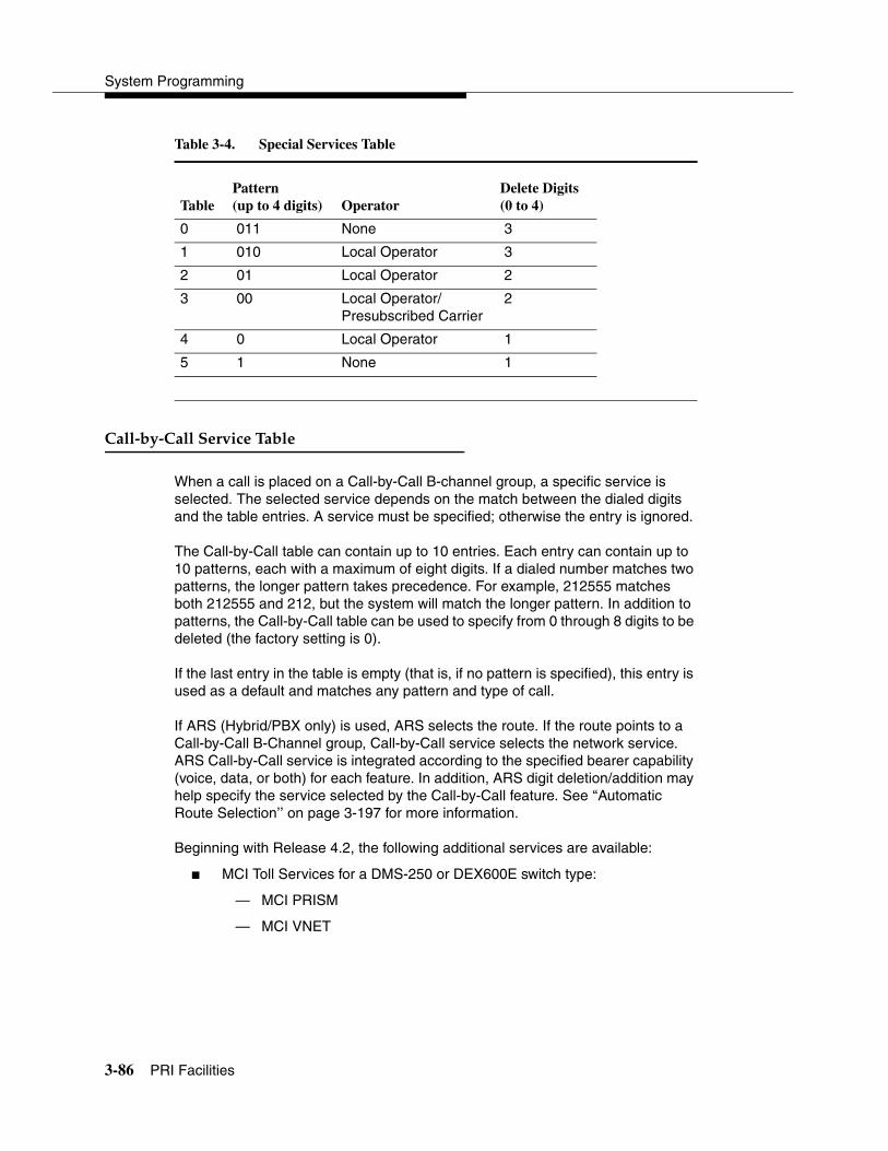
System Programming
3-86 PRI Facilities
Table 3-4. Special Services Table
%���$#�$%��������� ����#�� 3
When a call is placed on a Call-by-Call B-channel group, a specific service is selected. The selected service depends on the match between the dialed digits and the table entries. A service must be specified; otherwise the entry is ignored.
The Call-by-Call table can contain up to 10 entries. Each entry can contain up to 10 patterns, each with a maximum of eight digits. If a dialed number matches two patterns, the longer pattern takes precedence. For example, 212555 matches both 212555 and 212, but the system will match the longer pattern. In addition to patterns, the Call-by-Call table can be used to specify from 0 through 8 digits to be deleted (the factory setting is 0).
If the last entry in the table is empty (that is, if no pattern is specified), this entry is used as a default and matches any pattern and type of call.
If ARS (Hybrid/PBX only) is used, ARS selects the route. If the route points to a Call-by-Call B-Channel group, Call-by-Call service selects the network service. ARS Call-by-Call service is integrated according to the specified bearer capability (voice, data, or both) for each feature. In addition, ARS digit deletion/addition may help specify the service selected by the Call-by-Call feature. See ‘‘Automatic Route Selection’’ on page 3-197 for more information.
Beginning with Release 4.2, the following additional services are available:
� MCI Toll Services for a DMS-250 or DEX600E switch type:
— MCI PRISM
— MCI VNET
TablePattern (up to 4 digits) Operator
Delete Digits(0 to 4)
0 011 None 3
1 010 Local Operator 3
2 01 Local Operator 2
3 00 Local Operator/Presubscribed Carrier
2
4 0 Local Operator 1
5 1 None 1
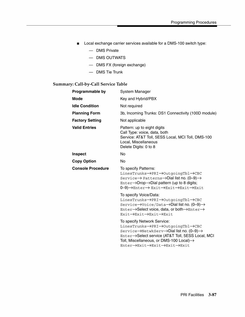
Programming Procedures
PRI Facilities 3-87
� Local exchange carrier services available for a DMS-100 switch type:
— DMS Private
— DMS OUTWATS
— DMS FX (foreign exchange)
— DMS Tie Trunk
���������%���$#�$%��������� ����#�� 3
Programmable by System Manager
Mode Key and Hybrid/PBX
Idle Condition Not required
Planning Form 3b, Incoming Trunks: DS1 Connectivity (100D module)
Factory Setting Not applicable
Valid Entries Pattern: up to eight digitsCall Type: voice, data, bothService: AT&T Toll, 5ESS Local, MCI Toll, DMS-100 Local, MiscellaneousDelete Digits: 0 to 8
Inspect No
Copy Option No
Console Procedure To specify Patterns:LinesTrunks→PRI→OutgoingTbl→CBC Service→ Patterns→Dial list no. (0–9)→ Enter→Drop→Dial pattern (up to 8 digits; 0–9)→Enter→ Exit→Exit→Exit→Exit
To specify Voice/Data:LinesTrunks→PRI→OutgoingTbl→CBC Service→Voice/Data→Dial list no. (0–9)→ Enter→Select voice, data, or both→Enter→ Exit→Exit→Exit→Exit
To specify Network Service:LinesTrunks→PRI→OutgoingTbl→CBC Service→NetwkServ→Dial list no. (0–9)→ Enter→Select service (AT&T Toll, 5ESS Local, MCI Toll, Miscellaneous, or DMS-100 Local)→ Enter→Exit→Exit→Exit→Exit

System Programming
3-88 BRI Facilities
To specify Delete Digits:LinesTrunks→PRI→OutgoingTbl→CBC Service→DeleteDigit→Dial list no.(0–9)→Enter→Drop→Dial no. of digits (0–8)→Enter→Exit→Exit→Exit→Exit
PC Procedure To specify Patterns:�→→�→�→�→Type list no. (0–9)→�→ + �→Type pattern (up to 8 digits; 0–9)→�→�→�→�→��
To specify Voice/Data:�→→�→�→�→Type list no.(0–9)→�→Select voice, data, or both→�→ �→�→�→�
To specify Network Service:�→→�→�→�→Type list no. (0–9)→ �→Select service (AT&T Toll, 5ESS Local, MCI Toll, Miscellaneous, or DMS-100 Local)→�→�→ �→�
To specify Delete Digits:�→→�→�→�→Dial list no. (0–9)→�→ + �→Dial no. of digits (0–8)→�→ �→�→�→�
����� ������ 3
The procedures in this section provide the steps for programming the following options for Basic Rate Interface (BRI) facilities connected to an 800 NI-BRI module:
� Service Profile Identifier (SPID) and Directory Number (DN)
� Timers
NOTES:� The 800 NI-BRI module is only available in Release 4.0 and later.
� If you are adding BRI facilities to an existing system, clock synchronization must be set correctly. To inspect or change these values, see ‘‘Clock Synchronization’’ on page 3-37.
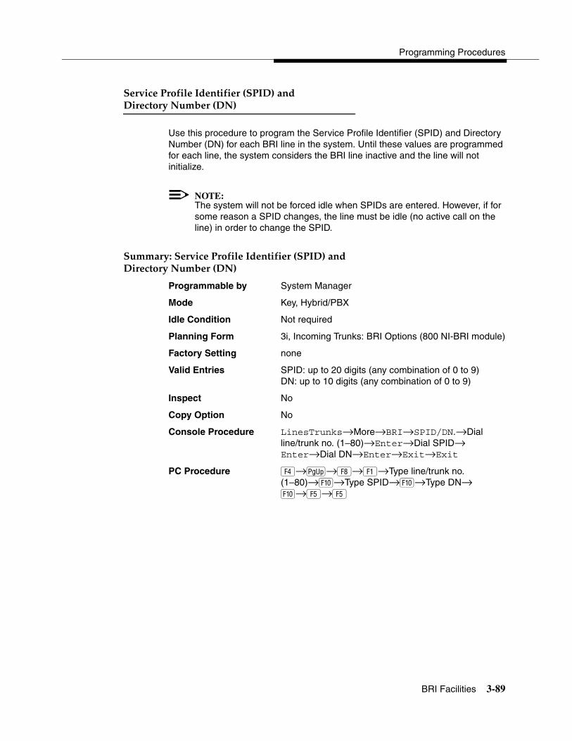
Programming Procedures
BRI Facilities 3-89
����� �����(����������(����*����+����
���� ���� "��#���*�"+ 3
Use this procedure to program the Service Profile Identifier (SPID) and Directory Number (DN) for each BRI line in the system. Until these values are programmed for each line, the system considers the BRI line inactive and the line will not initialize.
NOTE:The system will not be forced idle when SPIDs are entered. However, if for some reason a SPID changes, the line must be idle (no active call on the line) in order to change the SPID.
�������������� �����(����������(����*����+����
���� �����"��#���*�"+ 3
Programmable by System Manager
Mode Key, Hybrid/PBX
Idle Condition Not required
Planning Form 3i, Incoming Trunks: BRI Options (800 NI-BRI module)
Factory Setting none
Valid Entries SPID: up to 20 digits (any combination of 0 to 9)DN: up to 10 digits (any combination of 0 to 9)
Inspect No
Copy Option No
Console Procedure LinesTrunks→More→BRI→SPID/DN.→Dial line/trunk no. (1–80)→Enter→Dial SPID→ Enter→Dial DN→Enter→Exit→Exit
PC Procedure �→ →�→�→Type line/trunk no.(1–80)→�→Type SPID→�→Type DN→ �→�→�

System Programming
3-90 BRI Facilities
����� 3
Use this procedure to set timer thresholds.
! CAUTION:The factory settings for these thresholds are standard and rarely need to be changed. If you are not sure of the correct timer and threshold settings for your BRI lines and trunks, check with your Lucent Technologies representative before you make a change. Incorrect settings can cause your BRI lines and trunks to malfunction.
If the network does not respond before the programmed time, the system takes the appropriate corrective action.
The timers are listed below:
� T200 Timer. Minimum time that the link layer waits for an acknowledgment of a message sent from the communications system to the network.
� T203 Timer. Maximum time that the link layer can remain inactive.
� T303 Timer. Times the delay in network response when the communications system sends a setup message to initiate an outgoing call.
� T305 Timer. Times the delay in network response when the communications system sends a disconnect message to clear a call.
� T308 Timer. Times the delay in network response when the communications system sends a release message to clear a call.
NOTE:If you enter an invalid timer value, you hear an error beep and the value that was previously stored is displayed on the screen.
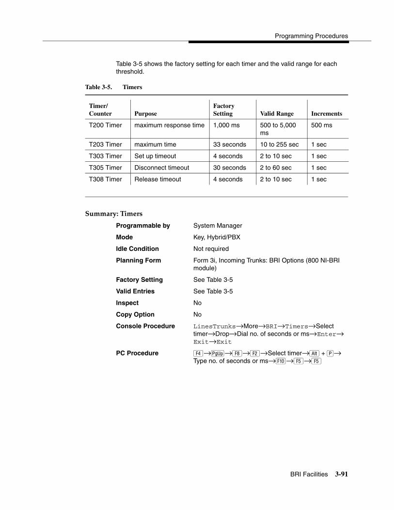
Programming Procedures
BRI Facilities 3-91
Table 3-5 shows the factory setting for each timer and the valid range for each threshold.
�������������� 3
Programmable by System Manager
Mode Key, Hybrid/PBX
Idle Condition Not required
Planning Form Form 3i, Incoming Trunks: BRI Options (800 NI-BRI module)
Factory Setting See Table 3-5
Valid Entries See Table 3-5
Inspect No
Copy Option No
Console Procedure LinesTrunks→More→BRI→Timers→Select timer→Drop→Dial no. of seconds or ms→Enter→ Exit→Exit
PC Procedure �→ →�→�→Select timer→ + �→Type no. of seconds or ms→�→�→�
Table 3-5. Timers
Timer/Counter Purpose
Factory Setting Valid Range Increments
T200 Timer maximum response time 1,000 ms 500 to 5,000 ms
500 ms
T203 Timer maximum time 33 seconds 10 to 255 sec 1 sec
T303 Timer Set up timeout 4 seconds 2 to 10 sec 1 sec
T305 Timer Disconnect timeout 30 seconds 2 to 60 sec 1 sec
T308 Timer Release timeout 4 seconds 2 to 10 sec 1 sec

System Programming
3-92 Extensions
3Programming Procedures
���������� 3
This section contains the following procedures:
� Assigning outside lines or trunks to the buttons on a telephone (including lines and trunks used for loudspeaker paging).
� Copying line button assignments from one extension to either an individual extension or a block of extensions.
� Assigning the following buttons on telephones (for Hybrid/PBX systems only):
— System Access or Intercom Voice
— System Access or Intercom Ring
— System Access or Intercom Originate Only
— Shared System or Intercom Access
� Identifying analog multiline telephones that do not have built-in speakerphones (BIS) or Hands-Free Answer on Intercom (HFAI) capability.
� Identifying analog multiline telephone extensions that require pairing of extension jacks to provide either the Voice Announce feature or Voice and Data features.
� Programming rotary signaling on tip/ring ports.
� Assigning tip/ring functionality on 412/016 ETR (enhanced tip/ring) module.
������ ������ �������������������� 3
Use this procedure to assign outside lines/trunks (connected to the control unit) to specific buttons on each telephone. The lines/trunks assigned to a button on a telephone are called personal lines.
This procedure is used only to change or add personal lines, Loudspeaker Paging, or Pool buttons (Hybrid/PBX only) to telephones. See ‘‘Assign Intercom or System Access Buttons’’ on page 3-97 to add or change Intercom (ICOM) or System Access (SA) buttons.
! SECURITY ALERT:In Release 6.0 and later systems (Hybrid/PBX mode only), do not assign private networked lines as personal lines on telephone buttons. Do not assign pools of private network trunks (tandem PRI or tandem tie) to telephones. Do not provide dial access to these pools. Use ARS to provide

Programming Procedures
Extensions 3-93
access to a remote networked system’s trunks for making outside calls. System users can reach extensions on the remote system by using normal inside calling procedures.
Individual lines/trunks can be assigned to a maximum of 64 extensions. Individual pools can be assigned as a Pool button on a maximum of 64 extensions.
The following lines/trunks cannot be assigned to a button on a telephone:
� Lines/trunks used for Music-On-Hold
� Lines/trunks used for maintenance alarms
NOTE:If you use equipment that rebroadcasts music or other copyrighted materials, you may be required to obtain a copyright license from and pay license fees to a third party (such as the American Society of Composers, Artists, and Producers or Broadcast Music Incorporated). Magic On Hold requires no such license and can be purchased from Lucent Technologies.
Pool buttons cannot be assigned to or removed from extensions unless the pool has trunks assigned. If all trunks are to be removed from a pool, all Pool button assignments must first be removed from extensions. Another way of handling this situation is to program another trunk into the pool and then remove the Pool button assignments from the extensions.
� Hybrid/PBX only. Individual lines/trunks assigned to a pool can be assigned to a button only on a DLC operator position. If one of the lines/trunks in a pool is assigned to a button on a non-DLC telephone, the result is a Pool button assignment.
� Key only. The system assigns the first eight line numbers to buttons on multiline telephones whether or not an outside line is physically connected. If a line is not connected, the button assignment must be removed so the user can assign a feature to the button.
� For the MDC 9000 and MLC-5 cordless multiline telephones and the MDW 9000 wireless multiline telephone. The system assigns the first eight lines connected to the control unit even though the telephone has fewer than eight buttons available. Remove the extra lines in system programming so that the appropriate number of lines is assigned to buttons on these telephones.
Lines and trunks are assigned to buttons in the order in which you presseach line button on the system programming console or keyboard. Existing line assignments can be rearranged by removing all current assignments and then pressing the line buttons on the console or keyboard in the order in which they should appear on the buttons. For information on the order of the programmed

System Programming
3-94 Extensions
buttons, refer to the button numbers on the applicable planning form for each telephone.
If you want to reserve some blank buttons for features between line buttons, a line must be assigned as a placeholder for each blank button. After all lines are assigned, remove the lines used as placeholders on the buttons reserved for features.
����� ��������� ������ �������������������� 3
Programmable by System Manager
Mode All, but note differences in factory settings.
Idle Condition Extension idle
Planning Form 4b, Analog Multiline Telephone4d, MLX Telephone4e, MFM Adjunct: MLX Telephone4f, Tip/Ring Equipment5a, Direct-Line Console (DLC): Analog5b, Direct-Line Console (DLC): Digital5c, MFM Adjunct: DLCData Form 1a, Modem Data WorkstationData Form 1b, ISDN Terminal Adapter Data Workstation
Factory Setting Key Mode. An Intercom Ring (ICOM Ring) button, an Intercom Voice (ICOM Voice) button, and the first eight lines connected to the control unit are assigned to all analog multiline telephones, MLX telephones (excluding operator positions), and MFMs connected to MLX telephones. Two ICOM Ring buttons are assigned to single-line telephones; no outside lines are assigned.
Behind Switch Mode. ICOM Ring, ICOM Voice, and prime line buttons are assigned to all analog multiline telephones, MLX telephones (excluding operator positions), and MFMs connected to MLX telephones. Two ICOM Ring buttons are assigned to single-line telephones; no outside lines are assigned. When prime lines are assigned to MLX extensions, lines are not assigned to MFMs used to connect adjuncts. Lines for MFMs must be assigned separately.
Hybrid/PBX Mode. System Access Ring (SA Ring), System Access Voice (SA Voice), and System Access Originate Only (SA Orig Only) buttons are assigned to all analog multiline telephones and MLX telephones

Programming Procedures
Extensions 3-95
(excluding operator positions). Five Call buttons are assigned to QCC operator positions. Two SA Ring buttons and one SA Orig Only button are assigned to single-line telephones. No personal line or Pool buttons are assigned.
Valid Entries Extension numbers
Inspect Yes
Copy Option Yes
Console Procedure To program a single line/trunk:Extensions→Lines/Trunks→Dial ext. no.→ Enter→Entry Mode→Dial line/trunk no.→ Enter→Exit→Exit
To program a block of lines/trunks:Extensions→Lines/Trunks→Dial ext. no.→Enter→Select trunk range→Toggle LED on/off→ Enter→Exit→Exit
PC Procedure To program a single line/trunk:�→�→Type ext. no.→�→�→ Type line/trunk no.→�→�→�
To program a block of lines/trunks: →��→ �→Type ext. no.→�→Select trunk range→Toggle letter G on/off→�→�→�
����������� ������������� 3
Use this procedure to copy outside line/trunk button assignments, pool dial-out code restrictions (Hybrid/PBX only), and (for operator positions only) Night Service information from one extension to another extension or block of extensions with identical requirements.
If you are copying assignments to a block of extensions and one of the extensions in the block is in use, the display shows the Station Busy - Pls Wait message. Copying for the rest of the extensions in the block is delayed until the busy extension becomes idle. The number of the busy extension is not shown. If a DSS is attached, the LED associated with the busy extension is on. If you exit instead of waiting for the busy extension to become idle, copying for the rest of the extensions is canceled; however, the assignments that have already been copied are not canceled.
If you are copying assignments from an operator position to a block of extensions that includes both operator and non-operator extensions, the information is copied to only the operator positions; the non-operator positions are not affected. Similarly, if you are copying assignments from a non-operator position to a block

System Programming
3-96 Extensions
of extensions that includes both operator and non-operator extensions, the information is copied to only the non-operator positions; the operator positions are not affected. The system does not provide an error tone to signal that the copy did not work for all of the extensions in the block.
����� �������������� ������������� 3
Programmable by System Manager
Mode All
Idle Condition Extension idle
Planning Form 4a, Extension Copy: Analog Multiline Telephone Template4c, Extension Copy: MLX Telephone Template
Factory Setting Not applicable
Valid Entries Not applicable
Inspect Yes: lines/pools assigned to an extension.
Copy Option Not applicable
Console Procedure To copy to a single extension:Extensions→Line Copy→Single→Dial copy from ext. no.→Enter→Dial copy to ext. no.→Enter→Exit→Exit
To copy to a block of extensions: Extensions→Line Copy→Block→Dial copy from ext. no.→Enter→Dial ext. no of first extension in block→Enter→Dial ext. no of last extension in block→Enter→Exit→Exit
PC Procedure To copy to a single extension:�→�→�→Type copy from ext. no.→�→ Type copy to ext. no.→�→�→�
To copy to a block of extensions:�→�→�→Type copy from ext. no.→�→Type ext. no. of first extension in block→�→Type ext. no. of last extension in block→�→�→�
Programming Procedures
Extensions 3-97
��������� ����� ��������������������� 3
Use this procedure to assign or change the assignments for Intercom (ICOM) buttons used to make and receive inside calls. This includes the following types of ICOM buttons:
� Ring
� Voice
� Originate Only (Ring or Voice)
In Hybrid/PBX mode only, use this procedure to assign or change assignments for System Access (SA) buttons used to make or receive inside and outside calls. This procedure includes the following types of System Access buttons:
� Ring
� Voice
� Originate Only (Ring or Voice)
� Shared (Ring or Voice)
NOTE:You cannot change the factory setting for Call buttons assigned to QCC operator positions, and you cannot assign Ring, Voice, Originate Only, or Shared buttons to QCC operator positions. In Release 4.0 and later, however, the Call 5 (Ring/Voice) button on a QCC can be programmed for Voice Announce. See ‘‘Voice Announce’’ on page 3-147.
System Access or Intercom buttons can be assigned to only the first 10 buttons on a telephone. This allows for a combination of up to 10 SA or ICOM buttons for each telephone (excluding QCC operator positions).
You can remove SA or ICOM buttons, but at least one must remain on the extension.
Although you can make selections from the screen (with the ListFeature option) to assign Ring and Voice buttons, the following procedure provides the programming codes to perform these functions. Using the codes speeds the button assignment process.
NOTE:When single-line sets are programmed with only one SA or ICOM button, the Transfer, Conference and Drop features are disabled. Other features that require a second dial tone, such as Account

System Programming
3-98 Extensions
Code/Number Entry, After Call Work States, Call Pickup, Call Waiting, and Privacy, are also affected. For more information, see the Feature Reference.
Each System Access Ring or Voice on an individual telephone can be assigned as a Shared System Access (SSA) button on up to 16 other extensions.
Shared SA buttons cannot be assigned to single-line telephones or other tip/ring equipment connected to an 016 (T/R), 012 (T/R), or 008 OPT module; or in Release 7.0 and later systems, to a 412 LS-ID-ETR and 016 ETR port when the port is programmed for T/R operation. Shared SA buttons can be assigned to a tip/ring or external alert device connected to an MFM in an MLX telephone or a GPA connected to an analog multiline telephone. Shared SA buttons cannot be assigned when the corresponding SA button is on a single-line set.
On Release 3.0 and later, each System Access Ring or Voice on an individual extension can be assigned as a Shared System Access (SSA) button on up to 27 other extensions.
SA and ICOM buttons are centrally programmed and cannot be programmed by individual extension users.
����� ������������ ����� ��������������������� 3
Programmable by System Manager
Mode All, but note differences in factory settings
Idle Condition Extension idle
Planning Form 4b, Analog Multiline Telephone4d, MLX Telephone4e, MFM Adjuncts: MLX Telephone4f, Tip/Ring Equipment5a, Direct-Line Console (DLC): Analog5b, Direct-Line Console (DLC): Digital5c, MFM Adjunct (DLC)Data Form 1a, Modem Data WorkstationData Form 1b, ISDN Terminal Adapter Data Workstation
Factory Setting Key Mode. An Intercom Ring (ICOM Ring) button, an Intercom Voice (ICOM Voice) button, and the first eight lines connected to the system are assigned to all analog multiline and MLX telephones, excluding operator positions. Two ICOM Ring buttons are

Programming Procedures
Extensions 3-99
assigned to tip/ring equipment connected to an 012 (T/R) and 016 (T/R) module, or in Release 7.0 and later systems, to a 412 LS-ID-ETR and 016 ETR port when the port is programmed for T/R operation. An ICOM Ring and an Intercom Originate Only (ICOM Orig Only) button are assigned to tip/ring equipment connected by an MFM. No outside lines are assigned.
Behind Switch Mode. An ICOM Ring button, an ICOM Voice button, and a prime line button are assigned to all analog multiline and MLX telephones, excluding operator positions. Two ICOM Ring buttons and a prime line button are assigned to tip/ring equipment connected to an 012 (T/R) and 016 (T/R) module, or in Release 7.0 and later systems, to a 412 LS-ID-ETR and 016 ETR port when the port is programmed for T/R operation. An ICOM Ring button and an Intercom Originate Only Ring button are assigned to tip/ring equipment connected by an MFM. No outside lines are assigned.
Hybrid/PBX Mode. System Access Ring (SA Ring), System Access Voice (SA Voice), and System Access Originate Only (SA Orig Only) buttons are assigned to all analog multiline and MLX telephones, excluding operator positions. Two SA Ring buttons and an SA Orig Only Ring button are assigned to tip/ring equipment (for example, single-line telephones or fax machines connected to an 012 (T/R) module). No personal line or pool buttons are assigned.
All Modes. System Access Ring (Hybrid/PBX mode) or Intercom Ring (Key and Behind Switch modes), System Access Voice (Hybrid/PBX mode) or Intercom Voice (Key and Behind Switch modes), and the first 18 through 29 lines connected to the control unit are assigned to all DLC operator positions. The number of lines assigned depends on the type of telephone used as a DLC operator position. Refer to the appropriate telephone planning form for details.
Valid Entries Not applicable.
Inspect Yes: specific button options.
Copy Option Yes. (You can copy additional SA buttons to another extension, but you cannot overwrite SA buttons that are already assigned.)

System Programming
3-100 Extensions
Console Procedure To program an extension:More→Cntr-Prg→Program Ext.→Dial ext. no.→Enter→Start→Program extension→Enter→Exit→Exit
To copy extension programming:More→Cntr-Prg→Copy ext.→Dial copy from ext. no.→Enter→Dial copy to ext. no.→Enter→ Exit→Exit
PC Procedure To program an extension:�→�→�→Type ext. no.→�→Program extension→�→�→�
To copy extension programming:�→�→�→Type copy from ext. no.→�→Type copy to ext. no.→�→�→�
Although you can make selections from the screen (with the ListFeature option) to assign Ring and Voice buttons, using programming codes to perform these functions speeds the button assignment process.
Table 3-6 provides the programming codes for assigning Ring and Voice buttons. You can handle errors in data entry as follows:
� If you enter a code incorrectly while programming, the display shows the Programming Error message and the red LED next to the button flashes. If this happens, press the button again and repeat the procedure.
� If you make a mistake and program the wrong feature on a button, press the button, select Delete (� on the PC), and press the button again.

Programming Procedures
Extensions 3-101
Table 3-6. Programming Codes for Assigning Buttons
������������������������� ������������!�������� ������"���#�� �$��%�!& ����� � ������� ����"$&�#�����'����� 3
Use this procedure to identify analog multiline telephones with flat membrane buttons that do not have BIS or HFAI capability. The models that must be identified are 5-button, 10-button, 34-button, and 34-button deluxe analog multiline models with flat membrane buttons.
Keep the factory setting for analog multiline models with raised plastic buttons, including the following models: 10-button HFAI, 34-button with speakerphone (SP-34), 34-button with speakerphone and display (SP-34D), BIS-10, BIS-22, BIS-34, BIS-22D, and BIS-34D.
To... On the console... On the PC...
Assign SA or ICOM Ring button
Dial *16 Type *16
Assign SA or ICOM Voice button
Dial *16, press button being programmed again, and dial *19
Type *16, press V + function key for button being programmed again, and type *19
Assign SA or ICOM Originate Only Ring button
Dial *18 Type *18
Assign SA or ICOM Originate Only Voice button
Dial *18, press button being programmed again, and dial *19
Type *18, press V + function key for button being programmed again, and type *19
Assign SA button Dial *17, press the extension number of principal telephone [nnnn] then press the button number being shared [nn]
Type *17, press the extension number of principal telephone [nnnn] then press the button number of specific button being shared [nn]
Change current assignment for SA or ICOM Voice, Originate Only or Shared SA buttons from Voice to Ring
Dial **19 Type **19

System Programming
3-102 Extensions
This procedure is not necessary for MLX or single-line telephones.
����� ����������������������������� ����������� �$&������'����� 3
Programmable by System Manager
Mode All
Idle Condition Not required
Planning Form 4b, Analog Multiline Telephone5a, Direct-Line Console (DLC): AnalogData Form 1a, Modem Data Workstations
Factory Setting All models of analog multiline telephones (except the analog multiline display console) have BIS/HFAI capability.
Valid Entries Extension numbers
Inspect Yes
Copy Option No
Console Procedure Extensions→BIS/HFAI→Dial ext. no.→Enter→ Exit→Exit.
PC Procedure �→→Type ext. no.→�→�→�
�������������������������� ����(������������&���� � 3
Use this procedure to dedicate a voice or voice pair to be used to provide the Voice Announce feature on an analog multiline telephone when it is busy.
The extension number associated with the first (odd-numbered) extension jack in the pair is the telephone’s extension number. The extension number for the second (even-numbered) extension jack is dedicated to the Voice Announce feature when the telephone is busy or off-hook. Calls cannot be placed to the extension jack reserved for the Voice Announce feature when the telephone is busy.
The Voice Announce feature must be disabled at data workstations.
NOTE:This procedure does not apply to MLX telephones (Voice Announce when the telephone is off-hook is automatically provided) and cannot be programmed for ETR, MLS, or single-line telephones.

Programming Procedures
Extensions 3-103
����� ����������������������������� ����(�������������&���� � 3
Programmable by System Manager
Mode All
Idle Condition System idle
Planning Form 4b, Analog Multiline Telephone 5a, Direct-Line Console (DLC) Analog Data Form 1a, Modem Data Workstation
Factory Setting Not applicable
Valid Entries Extension numbers
Inspect Yes
Copy Option Yes
Console Procedure Extensions→VoiceSignl→Dial ext. no.→Enter→ Exit→Exit
PC Procedure �→�→Type ext. no.→�→�→�
NOTE:‘‘Data Features’’ on page 3-228 provides information about analog multiline telephones in data workstations.
Although you can make selections from the screen (with the ListFeature option) to assign Ring and Voice buttons, the following procedure provides the programming codes to perform these functions. Using the codes speeds the button assignment process.
)��� �����������������)����� �� 3
Use this procedure to enable or disable rotary signaling on tip/ring ports. You can program any tip/ring port on an individual basis (including ports on the 412 LS-ID-ETR and 016 ETR modules that are programmed for tip/ring operation). The factory setting is that rotary signaling is disabled.
Whenever the system receives a rotary digit on a port, it determines if the port is programmed as rotary-enabled. If the port is rotary-enabled, the system processes the digit. If the port is not rotary-enabled, the digit is rejected. Touch-tone digits are always accepted by the port, regardless whether it is rotary-enabled or not.

System Programming
3-104 Extensions
����� ���)��� �����������������)����� �� 3
Programmable by System Manager
Mode All
Idle Condition System idle
Planning Form 4f
Factory Setting Touch-tone
Valid Entries Extension numbers for rotary dial telephones
Inspect Yes
Copy Option No
Console Procedure Extensions→More→More→RotaryEnabl→Type rotary ext. no.→Enter→Exit→Exit
PC Procedure �→�→→Type rotary ext. no.→ �→�→�
Although you can make selections from the screen (with the ListFeature option) to assign Ring and Voice buttons, the following procedure provides the programming codes to perform these functions. Using the codes speeds the button assignment process.
����)���&����������������*+,���!�-���)���%.+/���)���%���� 3
Use this procedure to assign either T/R or ETR functionality to ports on the 412 LS-ID-ETR or 016 ETR modules. For these ports, one or the other can be assigned, but not both simultaneously. The boards and corresponding ports include:
� 412 LS-ID-ETR: ports 9-12 can be ETR or T/R (ports 1–8 can be ETR only)
� 016 ETR: ports 11-16 can be ETR or T/R (ports 1–10 can be ETR only)
When a port on a 412 LS-ID-ETR or 016 ETR module is changed from ETR to T/R or from T/R to ETR, all programming assigned to the extension (such as inclusion in coverage groups and calling groups) is cleared and the extension is restored to the functionality defined with the factory settings (such as calling restrictions and button assignments).
NOTE:A system forced idle occurs when you perform this task. In addition to assigning either T/R or ETR functionality, with this task you are also able to determine whether a port on a 412 LS-ID-ETR or 016 ETR module has been administered as T/R or ETR. however, because this task forces the

Programming Procedures
Extensions 3-105
entire system into a forced idle state, it is recommended you do not use it to determine how the port has been administered. Instead, to determine the functionality of an ETR port, it is recommended that you do one of the following:
� Print an Extension Print Report. The report shows:
— “T/R” if the port is programmed as T/R.
— “ETR” if the port is programmed as ETR and an MLS or ETR telephone is connected to the port.
— “UNEQUIPPED” if the port is programmed as ETR and an MLS or ETR telephone is not connected to the port.
� View the extension profile by using this procedure: Maintenance→Port→Station→StatusThe profile shows the same information as previously listed for the Extensions Print Report.
����� �������)���&����������������*+,���!�-!��)���%�.+/���)���%���� 3
Programmable by System Manager
Mode All
Idle Condition System idle
Planning Form 4g
Factory Setting ETR
Valid Entries Tip/ring port
Inspect Yes
Copy Option No
Console Procedure Extensions→More→More→ETR→Type ext. no.→Enter→Select port type (ETR or Tip Ring)→Enter→Exit→Exit
PC Procedure �→�→�→→Type ext. no.→�→ Select port type (ETR or Tip Ring)→�→�→�

System Programming
3-106 Auxiliary Equipment
������ ���0������� 3
The procedures in this section describe the steps needed to perform the following:
� Identify the line/trunk jacks used for Music-On-Hold, loudspeaker paging, and maintenance alarms.
� Identify the extension jacks used for fax and CTI link.
� Specify parameters for MERLIN LEGEND Mail, Messaging 2000, Intuity AUDIX, MERLIN Mail Voice Messaging System (no longer orderable), Automated Attendant, and AUDIX Voice Power (no longer orderable).
�����!1�!$��% 3
Use this procedure to identify the line/trunk jack reserved for connection of a music source, such as a radio, tape player, or stereo system.
If you use equipment that rebroadcasts music or other copyrighted materials, you may be required to obtain a copyright license from and pay license fees to a third party [such as the American Society of Composers, Artists, and Producers (ASCAP) or Broadcast Music Incorporated (BMI)]. Magic On Hold requires no such license and can be purchased from your Lucent Technologies dealer.
Only one Music-On-Hold line/trunk jack is allowed per system.
You cannot assign the line/trunk identified for Music-On-Hold to a line/trunk pool. If the line/trunk is currently assigned to a pool, you must remove it before you program this option.
You cannot assign the line/trunk identified for use with Music-On-Hold to a button on any extension or as a Remote Access trunk, and you cannot use the line/trunk jack identified for Music-On-Hold for a loudspeaker paging system or maintenance alarm.
In Release 6.0 and later systems, each system in a private network must have its own music source. A music source connected to a remote private networked switch cannot be used by the local system.
Although you can make selections from the screen (with the ListFeature option) to assign Ring and Voice buttons, the following procedure provides the programming codes to perform these functions. Using the codes speeds the button assignment process.

Programming Procedures
Auxiliary Equipment 3-107
����� ��������!1�!$��% 3
Programmable by System Manager
Mode All, but in Hybrid/PBX mode the line/trunk designated for Music-On-Hold cannot be assigned to a line/trunk pool.
Idle Condition System idle
Planning Form 2c, System Numbering: Line/Trunk Jacks
Factory Setting Not Applicable
Valid Entries Line/trunk number
Inspect No
Copy Option No
Console Procedure AuxEquip→MusicOnHold→Dial line/trunk no.→ Enter→Exit
PC Procedure �→�→Type line/trunk no.→�→�
Although you can make selections from the screen (with the ListFeature option) to assign Ring and Voice buttons, the following procedure provides the programming codes to perform these functions. Using the codes speeds the button assignment process.
���%������ ����� 3
Use this procedure to identify the line/trunk jack reserved for connection of loudspeaker paging equipment.
If you use equipment that rebroadcasts music or other copyrighted materials, you may be required to obtain a copyright license from and pay license fees to a third party (such as ASCAP or BMI). Magic On Hold requires no such license and can be purchased from your Lucent Technologies dealer.
A maximum of three single-zone or multizone loudspeaker paging systems can be connected to the system.
You cannot assign the line/trunk identified for loudspeaker paging equipment to a line/trunk pool. If the line/trunk is currently assigned to a pool, you must remove it before you program this option.
You cannot assign the line/trunk identified for loudspeaker paging equipment as a Remote Access line/trunk, and you cannot use its jack for Music-On-Hold or maintenance alarm.
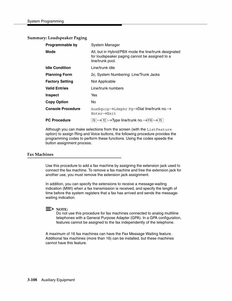
System Programming
3-108 Auxiliary Equipment
����� ������%������ ����� 3
Programmable by System Manager
Mode All, but in Hybrid/PBX mode the line/trunk designated for loudspeaker paging cannot be assigned to a line/trunk pool.
Idle Condition Line/trunk idle
Planning Form 2c, System Numbering: Line/Trunk Jacks
Factory Setting Not Applicable
Valid Entries Line/trunk numbers
Inspect Yes
Copy Option No
Console Procedure AuxEquip→Ldspkr Pg→Dial line/trunk no.→Enter→Exit
PC Procedure �→�→Type line/trunk no.→�→�
Although you can make selections from the screen (with the ListFeature option) to assign Ring and Voice buttons, the following procedure provides the programming codes to perform these functions. Using the codes speeds the button assignment process.
&����������� 3
Use this procedure to add a fax machine by assigning the extension jack used to connect the fax machine. To remove a fax machine and free the extension jack for another use, you must remove the extension jack assignment.
In addition, you can specify the extensions to receive a message-waiting indication (MWI) when a fax transmission is received, and specify the length of time before the system registers that a fax has arrived and sends the message-waiting indication.
NOTE:Do not use this procedure for fax machines connected to analog multiline telephones with a General Purpose Adapter (GPA). In a GPA configuration, features cannot be assigned to the fax independently of the telephone.
A maximum of 16 fax machines can have the Fax Message Waiting feature. Additional fax machines (more than 16) can be installed, but these machines cannot have this feature.
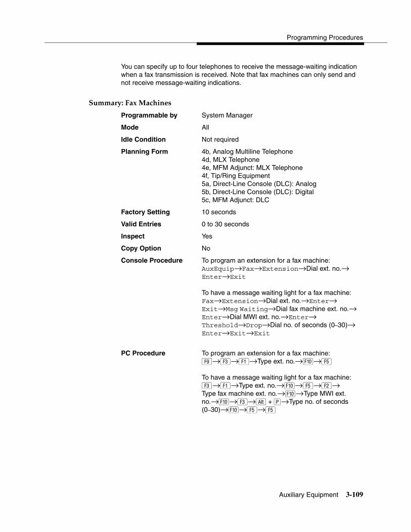
Programming Procedures
Auxiliary Equipment 3-109
You can specify up to four telephones to receive the message-waiting indication when a fax transmission is received. Note that fax machines can only send and not receive message-waiting indications.
����� ���&����������� 3
Programmable by System Manager
Mode All
Idle Condition Not required
Planning Form 4b, Analog Multiline Telephone4d, MLX Telephone4e, MFM Adjunct: MLX Telephone4f, Tip/Ring Equipment5a, Direct-Line Console (DLC): Analog5b, Direct-Line Console (DLC): Digital5c, MFM Adjunct: DLC
Factory Setting 10 seconds
Valid Entries 0 to 30 seconds
Inspect Yes
Copy Option No
Console Procedure To program an extension for a fax machine:AuxEquip→Fax→Extension→Dial ext. no.→Enter→Exit
To have a message waiting light for a fax machine:Fax→Extension→Dial ext. no.→Enter→ Exit→Msg Waiting→Dial fax machine ext. no.→ Enter→Dial MWI ext. no.→Enter→Threshold→Drop→Dial no. of seconds (0–30)→ Enter→Exit→Exit
PC Procedure To program an extension for a fax machine:�→�→�→Type ext. no.→�→�
To have a message waiting light for a fax machine:�→�→Type ext. no.→�→�→�→ Type fax machine ext. no.→�→Type MWI ext. no.→�→�→ �+ �→Type no. of seconds (0–30)→�→�→�
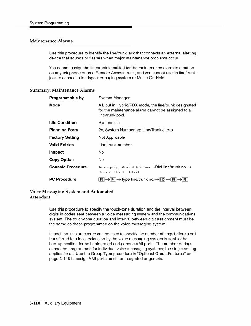
System Programming
3-110 Auxiliary Equipment
�������������� �� 3
Use this procedure to identify the line/trunk jack that connects an external alerting device that sounds or flashes when major maintenance problems occur.
You cannot assign the line/trunk identified for the maintenance alarm to a button on any telephone or as a Remote Access trunk, and you cannot use its line/trunk jack to connect a loudspeaker paging system or Music-On-Hold.
����� ����������������� �� 3
Programmable by System Manager
Mode All, but in Hybrid/PBX mode, the line/trunk designated for the maintenance alarm cannot be assigned to a line/trunk pool.
Idle Condition System idle
Planning Form 2c, System Numbering: Line/Trunk Jacks
Factory Setting Not Applicable
Valid Entries Line/trunk number
Inspect No
Copy Option No
Console Procedure AuxEquip→MaintAlarms→Dial line/trunk no.→Enter→Exit→Exit
PC Procedure �→�→Type line/trunk no.→�→�→�
(����������������������%��������%�����%��� 3
Use this procedure to specify the touch-tone duration and the interval between digits in codes sent between a voice messaging system and the communications system. The touch-tone duration and interval between digit assignment must be the same as those programmed on the voice messaging system.
In addition, this procedure can be used to specify the number of rings before a call transferred to a local extension by the voice messaging system is sent to the backup position for both integrated and generic VMI ports. The number of rings cannot be programmed for individual voice messaging systems; the single setting applies for all. Use the Group Type procedure in ‘‘Optional Group Features’’ on page 3-148 to assign VMI ports as either integrated or generic.

Programming Procedures
Auxiliary Equipment 3-111
NOTE:This does not apply to calls transferred to a non-local extension. See the Network Reference for information.
! SECURITY ALERT:See ‘‘Security Risks Associated with the Automated Attendant Feature of Voice Messaging Systems’’ on page A-14 and ‘‘Security Risks Associated with Transferring through Voice Messaging Systems’’ on page A-12 in Appendix A, ‘‘Customer Support Information,” for details on preventing toll fraud.
����� ���(����������������������%��������%�����%��� 3
Programmable by System Manager
Mode All
Idle Condition Not required
Planning Form See forms packaged with application
Factory Setting Touch-tone duration: 100 ms Interval between digits: 50 ms Number of rings before transfer sent to backup: 4
Valid Entries Touch-tone duration: 50 to 200 ms, in increments of25 msInterval between digits: 50 to 200 ms, in increments of 25 msNumber of rings before transfer sent to backup: 0 to 9
Inspect No
Copy Option No
Console Procedure AuxEquip→VMS/AA→TransferRtn→Drop→Dial no. of rings (0–9)→Enter→TT Duration→ Drop→ Dial no. of ms (50–200 ms, in increments of 25 ms)→ Enter→TT Interval→Drop→Dial no. of ms (50–200 ms, in increments of 25 ms)→Enter→ Exit→Exit
PC Procedure �→�→�→ + �→Type no. of rings (0–9)→�→�→ + �→Type no. of ms (50–200 ms, in increments of 25 ms)→�→�→ �+��→Type no. of ms (50–200 ms, in increments of 25 ms)→�→�→�

System Programming
3-112 Computer Telephony Integration (CTI) Link
������� ��������������� ������"���# ���� 3
Release 5.0 and later systems support the use of an MLX port as a Computer Telephony Integration (CTI) link on Hybrid/PBX mode systems. The CTI link feature allows CTI applications to interact with the MERLIN LEGEND Communications System over a local area network (LAN). The CTI link is the system’s hardware and software interface to the Lucent Technologies PassageWay Telephony Services product, which supports the Windows® 95, Windows NT, Windows 3.1, Windows 3.11 for Workgroups, Apple® Macintosh® OS and UNIX® systems platforms on the client side. CTI link circuitry connects to an MLX port on the system and to a LAN server using Novell NetWare (releases 3.12, 4.1, and 4.11) or Windows NT 4.0 Server or Workstation software (Server is recommended).
� � ���������������� 3
Before programming a CTI link, refer to the Feature Reference, System Planning, and the documentation provided with the telephony platform.
The following constraints apply to programming an MLX port as a CTI link:
� CTI links cannot be used with communications systems operating in Key mode or Behind Switch mode.
� CTI link extensions cannot be programmed on tip/ring or analog multiline extension module ports. You must chose a free extension jack on an MLX extension module. The free extension jack cannot be the first or fifth port on an 008 MLX, 408 GS/LS-MLX, or 408 GS/LS-ID-MlX module; or the first, fifth, ninth, or thirteenth port on an 016 MLX module (Release 7.0 and later systems).
� You cannot use a port reserved for an operator extension as the CTI link extension.
� You cannot use a system programming port as the CTI link extension.
� You cannot program a port as a CTI link if it has a telephone or other equipment connected to it.
� MLX modules with firmware vintage 29 do not work correctly with the CTI link. You must either choose a port on a board with firmware vintage that is not 29 or replace the module with a module that has a firmware vintage other than 29.

Programming Procedures
Computer Telephony Integration (CTI) Link 3-113
NOTES:� You should choose a module other than the one that has the system
programming port so that you can still perform maintenance and system programming when the board with the CTI link extension is busied-out.
� Be sure to busy-out the board with the CTI link before starting any programming activities.
When you add a CTI link, the system performs the following actions:
� The programmed buttons for that extension revert to the factory settings for a non-operator MLX telephone.
� Forwarding is deactivated to the extension.
� The extension is removed from membership in calling groups.
� The extension is removed from membership in coverage groups.
� The extension is removed from membership in Service Observing groups, or as an Observer of a Service Observing group.
� The Extension Directory label for the extension is changed to CTILINK.
� The factory setting for alarms is active on this link.
� Dial access to pools is removed from the station.
NOTES:� Be sure to restore the board after finishing any programming activities.
� If the primary and secondary cover buttons are not removed, the following message appears on the programming device (SPM or MLX-20L):
CTI Link Extension xxxx added, but it has primary or secondary cover buttons at other extensions. Please remove them.Exit
Although you can make selections from the screen (with the ListFeature option) to assign Ring and Voice buttons, the following procedure provides the programming codes to perform these functions. Using the codes speeds the button assignment process.

System Programming
3-114 Computer Telephony Integration (CTI) Link
����� ����������� 3
Programmable by System Manager
Mode Hybrid/PBX
Idle Condition Not required
Planning Form 2b, System Numbering: Digital Adjuncts
Factory Setting No port programmed as CTI link
Valid Entries Any extension on an MLX port board except the System Programming console port and the first and fifth ports.
Inspect Yes
Copy Option No
Console Procedure Busy out the board first. This is a Maintenance step. Start the procedure from the main menu, not the System Programming screen.Menu→Maintenance→Slot→Dial slot no. (1–17)→Enter→Busy-Out→Yes
Program the CTI link:AuxEquip→CTI Link→Dial extension no.→Enter→ Exit→Exit
Restore the slot. This is a Maintenance step. Start the procedure from the main menu, not the System Programming screen.Menu→Maintenance→Slot→Dial slot no. (1–17)→Enter→Restore→Yes
PC Procedure Busy out the board first:�→�→Type slot no. (1–17)→�→�→�
Program the CTI link:�→→Type extension number→�→�→�
Restore the slot. This is a Maintenance step. Start the procedure from the main menu, not the System Programming screen.�→�→Dial slot no. (1–17)→�→�→�
Although you can make selections from the screen (with the ListFeature option) to assign Ring and Voice buttons, the following procedure provides the programming codes to perform these functions. Using the codes speeds the button assignment process.

Programming Procedures
Computer Telephony Integration (CTI) Link 3-115
Although you can make selections from the screen (with the ListFeature option) to assign Ring and Voice buttons, the following procedure provides the programming codes to perform these functions. Using the codes speeds the button assignment process.
���������� � ������� � � 3
During the programming of the CTI link, entering an inappropriate extension number can give you an error message. This section contains displays of each screen and information about what to do if the screen appears.
�������2������$�' �%���3���%� 3
This message appears if the communications system is not in Hybrid/PBX mode. CTI links cannot be used with communications systems operating in Key mode or Behind Switch mode.
�����������������%�2��������3��� ����%��� 3
This message appears if you have chosen an extension that is not on an MLX Port Module. CTI link extensions cannot be programmed on tip/ring or analog multiline extension module ports. You must chose an extension that is on an MLX port module (008 MLX or 408 MLX).
CTI Link Extensions:
Extension xxxx Failed.
System Not in
Hybrid/PBX Mode.
Exit
CTI Link Extensions:
Extension xxxx Failed.
Not on MLX Port Module.
Exit
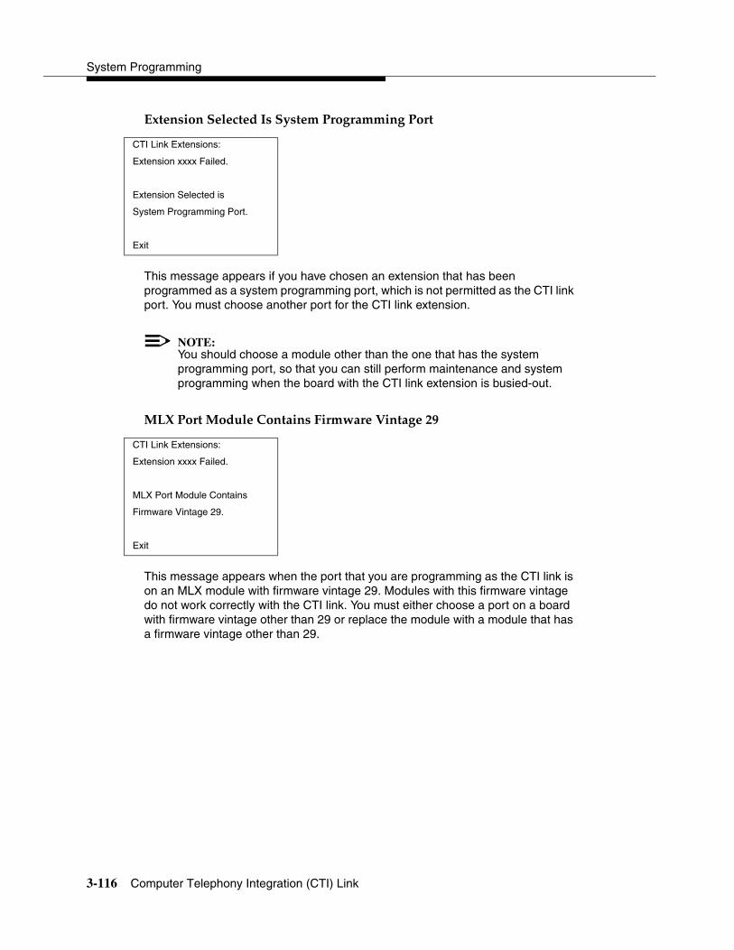
System Programming
3-116 Computer Telephony Integration (CTI) Link
�����������������%������������ � �������� � 3
This message appears if you have chosen an extension that has been programmed as a system programming port, which is not permitted as the CTI link port. You must choose another port for the CTI link extension.
NOTE:You should choose a module other than the one that has the system programming port, so that you can still perform maintenance and system programming when the board with the CTI link extension is busied-out.
��3��� ����%�������������&� � � ��(������,4 3
This message appears when the port that you are programming as the CTI link is on an MLX module with firmware vintage 29. Modules with this firmware vintage do not work correctly with the CTI link. You must either choose a port on a board with firmware vintage other than 29 or replace the module with a module that has a firmware vintage other than 29.
CTI Link Extensions:
Extension xxxx Failed.
Extension Selected is
System Programming Port.
Exit
CTI Link Extensions:
Extension xxxx Failed.
MLX Port Module Contains
Firmware Vintage 29.
Exit
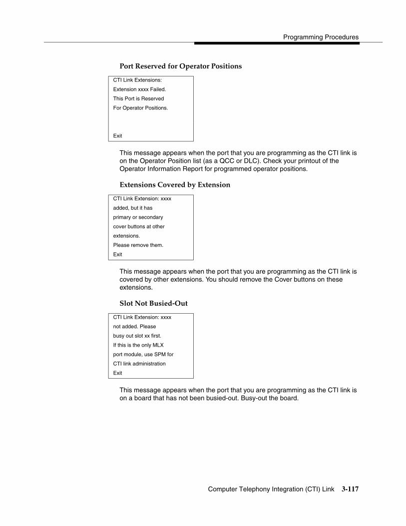
Programming Procedures
Computer Telephony Integration (CTI) Link 3-117
�� ��)��� 5�%�6� �1�� ��� ���������� 3
This message appears when the port that you are programming as the CTI link is on the Operator Position list (as a QCC or DLC). Check your printout of the Operator Information Report for programmed operator positions.
�������������5� �%�'����������� 3
This message appears when the port that you are programming as the CTI link is covered by other extensions. You should remove the Cover buttons on these extensions.
�����2��������%!1�� 3
This message appears when the port that you are programming as the CTI link is on a board that has not been busied-out. Busy-out the board.
CTI Link Extensions:
Extension xxxx Failed.
This Port is Reserved
For Operator Positions.
Exit
CTI Link Extension: xxxx
added, but it has
primary or secondary
cover buttons at other
extensions.
Please remove them.
Exit
CTI Link Extension: xxxx
not added. Please
busy out slot xx first.
If this is the only MLX
port module, use SPM for
CTI link administration
Exit

System Programming
3-118 Optional Extension Features
1������������������&���� �� 3
The summaries in this section detail the steps in programming the following optional features:
� Extension Language
� Pool Dial-Out Code
� Calling Restrictions
� Copy Calling Restrictions
� ARS Restriction Level for Extensions
� Forced Account Code Entry
� Microphone Operation
� Authorization Codes
� Remote Call Forwarding
� Delayed Call Forwarding
� Trunk-to-Trunk Transfer
� Primary Cover Ring Delay
� Secondary Cover Ring Delay
� Group Coverage Ring Delay
� Hotline (single-line telephone only)
� Display Preference
� Service Observing
���������������� 3
Use this procedure to change the language for an MLX telephone. It applies to Releases 1.1 and later only.
����� ������������������� 3
Programmable by Users and system manager
Mode All
Idle Condition Not required
Planning Form 4d, MLX Telephone5b, Direct-Line Console (DLC): Digital Data Data Form 1b, ISDN Terminal Adapter Data Workstation
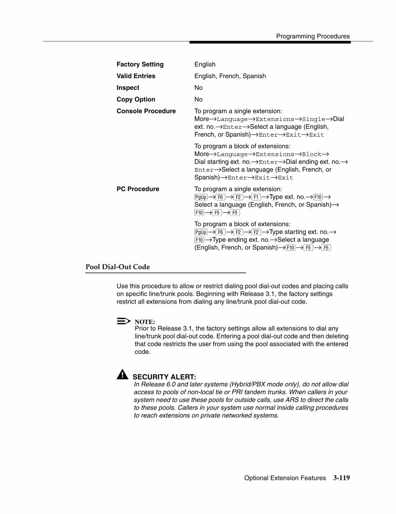
Programming Procedures
Optional Extension Features 3-119
Factory Setting English
Valid Entries English, French, Spanish
Inspect No
Copy Option No
Console Procedure To program a single extension:More→Language→Extensions→Single→Dial ext. no.→Enter→Select a language (English, French, or Spanish)→Enter→Exit→Exit
To program a block of extensions:More→Language→Extensions→Block→Dial starting ext. no.→Enter→Dial ending ext. no.→ Enter→Select a language (English, French, or Spanish)→Enter→Exit→Exit
PC Procedure To program a single extension:�→�→�→�→Type ext. no.→�→Select a language (English, French, or Spanish)→�→�→�
To program a block of extensions:�→�→�→�→Type starting ext. no.→�→Type ending ext. no.→Select a language (English, French, or Spanish)→�→�→�
�����-���!1�����%� 3
Use this procedure to allow or restrict dialing pool dial-out codes and placing calls on specific line/trunk pools. Beginning with Release 3.1, the factory settings restrict all extensions from dialing any line/trunk pool dial-out code.
NOTE:Prior to Release 3.1, the factory settings allow all extensions to dial any line/trunk pool dial-out code. Entering a pool dial-out code and then deleting that code restricts the user from using the pool associated with the entered code.
! SECURITY ALERT:In Release 6.0 and later systems (Hybrid/PBX mode only), do not allow dial access to pools of non-local tie or PRI tandem trunks. When callers in your system need to use these pools for outside calls, use ARS to direct the calls to these pools. Callers in your system use normal inside calling procedures to reach extensions on private networked systems.

System Programming
3-120 Optional Extension Features
����� ��������-���!1�����%� 3
Programmable by System Manager
Mode Hybrid/PBX
Idle Condition Extension idle
Planning Form 4b, Analog Multiline Telephone4d, MLX Telephone4e, MFM Adjunct: MLX Telephone4f, Tip/Ring Equipment5a, Direct-Line Console (DLC): Analog5b, Direct-Line Console (DLC): Digital5c, MFM Adjunct (DLC): Digital5d, Queued Call Console (QCC)Data Form 1a, Modem Data WorkstationData Form 1b, ISDN Terminal Adapter Data Workstation
Factory Setting Main pool: 70; All other pools: 890 to 899. All telephones are restricted from dialing any pool dial-out code.
Valid Entries Pool numbers
Inspect Yes
Copy Option No
Console Procedure Extensions→Dial OutCd→Dial ext. no.→Enter→Dial pool dial-out code→Enter→Exit→Exit
PC Procedure �→�→Type ext. no.→�→Type pool dial-out code→ �→�→�
Although you can make selections from the screen (with the ListFeature option) to assign Ring and Voice buttons, the following procedure provides the programming codes to perform these functions. Using the codes speeds the button assignment process.
�������)��� ������� 3
Use this procedure to change individual extension calling restrictions to one of the following:
� Unrestricted
� Restricted from making all outgoing calls
� Restricted from making toll calls

Programming Procedures
Optional Extension Features 3-121
! SECURITY ALERT:Toll fraud can occur if extensions are not properly restricted. See ‘‘Security of Your System: Preventing Toll Fraud’’ on page A-8 in Appendix A for more information and security procedures.
NOTE:In Release 6.0 and later systems, outward and toll calling restrictions are automatically removed when a caller dials an extension in the non-local dial plan. FRL restrictions still apply. For details, see ‘‘Uniform Dial Plan Routing’’ on page 3-208.
����� ����������)��� ������� 3
Programmable by System Manager
Mode All
Idle Condition Extension idle
Planning Form 4b, Analog Multiline Telephone4d, MLX Telephone4e, MFM Adjunct: MLX Telephone4f, Tip/Ring Equipment5a, Direct-Line Console (DLC): Analog5b, Direct-Line Console (DLC): Digital5c, MFM Adjunct: DLC5d, Queued Call Console (QCC)Data Form 1a, Modem Data WorkstationData Form 1b, ISDN Terminal Adapter Data Workstation
Factory Setting Unrestricted
Valid Entries Unrestricted, Outward restricted, Toll restricted
Inspect No
Copy Option Yes
Console Procedure Extensions→Restriction→Dial ext. no.→Enter→Select restriction (Unrestricted, Outward restricted, or Toll restricted)→Enter→Exit
PC Procedure �→�→Type ext. no.→�→Select restriction (Unrestricted, Outward restricted, or Toll restricted)→�→�

System Programming
3-122 Optional Extension Features
������������)��� ������� 3
Use this procedure to copy calling restrictions, allowed lists, and disallowed lists. Feature assignment must be completed for the “copy from” extension. These features can then be copied to an individual extension or block of extensions with identical calling restriction requirements.
If you are copying restrictions to a block of extensions and one of the extensions in the block is in use, the display shows the Station Busy - Pls Wait message. Copying for the rest of the extensions in the block is delayed until the busy extension becomes idle. The number of the busy extension is not shown. If a DSS is attached, the LED associated with the busy extension is on. If you exit instead of waiting for the busy extension to become idle, copying for the rest of the extensions in the block is canceled; however, the restrictions that have already been copied are not canceled.
If you are copying restrictions to a block of extensions, they must be sequentially numbered.
The extensions you are copying to and from can be both operator and nonoperator positions.
NOTE:Dial-out code restrictions are not copied.
����� ���������������)��� ������� 3
Programmable by System Manager
Mode All
Idle Condition “Copy to” extension or extensions idle
Planning Form 4b, Analog Multiline Telephone4d, MLX Telephone4e, MFM Adjunct: MLX Telephone5a, Direct-Line Console (DLC): Analog5b, Direct-Line Console (DLC): Digital5c, MFM Adjunct: DLC5d, Queued Call Console (QCC)Data Form 1a, Modem Data WorkstationData Form 1b, ISDN Terminal Adapter Data Workstation
Factory Setting Not applicable
Valid Entries Not applicable
Inspect No
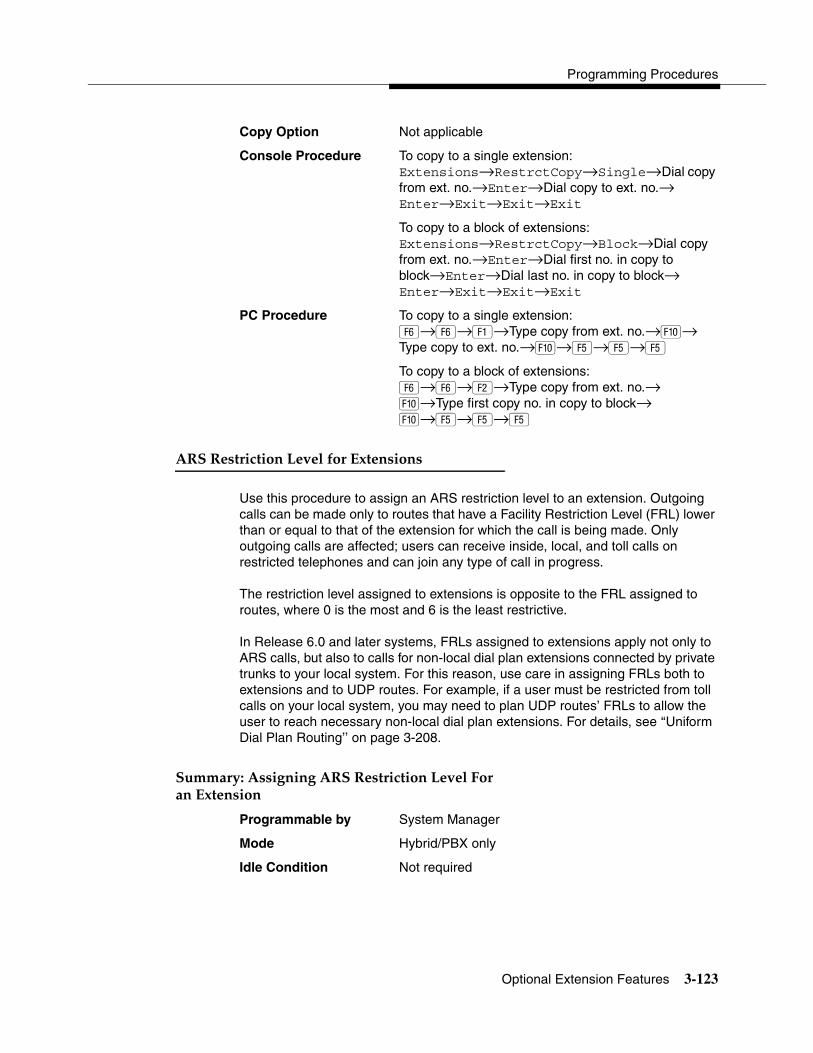
Programming Procedures
Optional Extension Features 3-123
Copy Option Not applicable
Console Procedure To copy to a single extension:Extensions→RestrctCopy→Single→Dial copy from ext. no.→Enter→Dial copy to ext. no.→ Enter→Exit→Exit→Exit
To copy to a block of extensions:Extensions→RestrctCopy→Block→Dial copy from ext. no.→Enter→Dial first no. in copy to block→Enter→Dial last no. in copy to block→Enter→Exit→Exit→Exit
PC Procedure To copy to a single extension:�→�→�→Type copy from ext. no.→�→Type copy to ext. no.→�→�→�→�
To copy to a block of extensions:�→�→�→Type copy from ext. no.→�→Type first copy no. in copy to block→�→�→�→�
)��)��� ���������5���6� ����������� 3
Use this procedure to assign an ARS restriction level to an extension. Outgoing calls can be made only to routes that have a Facility Restriction Level (FRL) lower than or equal to that of the extension for which the call is being made. Only outgoing calls are affected; users can receive inside, local, and toll calls on restricted telephones and can join any type of call in progress.
The restriction level assigned to extensions is opposite to the FRL assigned to routes, where 0 is the most and 6 is the least restrictive.
In Release 6.0 and later systems, FRLs assigned to extensions apply not only to ARS calls, but also to calls for non-local dial plan extensions connected by private trunks to your local system. For this reason, use care in assigning FRLs both to extensions and to UDP routes. For example, if a user must be restricted from toll calls on your local system, you may need to plan UDP routes’ FRLs to allow the user to reach necessary non-local dial plan extensions. For details, see ‘‘Uniform Dial Plan Routing’’ on page 3-208.
����� ����������)��)��� ���������5���&� ������������� 3
Programmable by System Manager
Mode Hybrid/PBX only
Idle Condition Not required

System Programming
3-124 Optional Extension Features
Planning Form 4b, Analog Multiline Telephone4d, MLX Telephone4e, MFM Adjunct: MLX Telephone4f, Tip/Ring Equipment5a, Direct-Line Console (DLC): Analog5b, Direct-Line Console (DLC): Digital5c, MFM Adjunct: DLC6g, Call Restriction Assignments and Lists
Factory Setting 3
Valid Entries 0–6 (0 is most restrictive and 6 is least restrictive)
Inspect No
Copy Option No
Console Procedure Extensions→More→ARS Restrict→Dial ext. no.→ Enter→Drop→Dial restriction level (0–6)→Enter→Exit
PC Procedure �→�→�→Type ext. no.→�→ + �→Type restriction level (0–6)→�→�
&� ��%����������%����� � 3
Use this procedure to assign or remove Forced Account Code Entry. When this feature is programmed on individual extensions, the user must enter a 1- to 16-digit account code before making an outside call.
����� ���&� ��%����������%����� � 3
Programmable by System Manager
Mode All
Idle Condition Not required
Planning Form 4b, Analog Multiline Telephone4d, MLX Telephone4e, MFM Adjunct: MLX Telephone4f, Tip/Ring Equipment5a, Direct-Line Console (DLC): Analog5b, Direct-Line Console (DLC): Digital5c, MFM Adjunct: DLC5d, Queued Call Console (QCC)Data Form 1a, Modem Data WorkstationData Form 1b, ISDN Terminal Adapter Data Workstation
Factory Setting Not assigned

Programming Procedures
Optional Extension Features 3-125
Valid Entries Assigned, not assigned
Inspect Yes
Copy Option No
Console Procedure Extensions→Account→Toggle LED on/off or dial ext. no.→Enter→Exit→Exit
PC Procedure �→→Toggle letter R on/off or type ext. no.→ �→�→�
��� �������1�� ����� 3
Use this procedure to enable or disable microphones on MLX telephones (except QCC operator positions). When the microphone is disabled, users cannot use the speakerphone to conduct conversations.
NOTE:The microphone cannot be disabled on analog multiline telephones or on MLX telephones used as QCC operator positions.
����� ������ �������1�� ����� 3
Programmable by System Manager
Mode All
Idle Condition Not required
Planning Form 4d, MLX Telephone5b, Direct-Line Console (DLC): Digital
Factory Setting Enabled
Valid Entries Enabled, Disabled
Inspect Yes
Copy Option No
Console Procedure Extensions→More→Mic Disable→Toggle LED on/off or dial ext. no.→Enter→Exit→Exit
PC Procedure �→�→→Toggle letter R on/off or type ext. no.→�→�→�

System Programming
3-126 Optional Extension Features
���� �7��������%�� 3
The Authorization Code feature allows you to pick up someone else’s telephone, enter your authorization code, and complete a call with the restrictions that apply to your own telephone (home extension). This includes toll restrictions, outward restriction, FRL, Allowed Lists, Disallowed Lists, Forced Account Code Entry (FACE), Night Service Exclusion List, and Dial Access to Pools.
NOTE:In Release 6.0 and later systems, a user can activate Call Forwarding and Remote Call Forwarding by entering his or her home extension authorization code while at any telephone in the system; this is useful when activating Call Forwarding or Remote Call Forwarding at phantom stations. It is also useful when a single-line telephone extension needs a PAUSE character in the Remote Call Forwarding digit string.
Use this procedure to assign or remove an authorization code to an extension. The authorization code can range from 2 to 11 characters (0 – 9, *) and must be unique for each extension. An authorization code cannot begin with an “*”.
If you are assigning authorization codes for a group of sequential extensions, begin programming the lowest extension number to take advantage of the Next screen key (see “Standard Procedures”).
����� ������� �7��������%�� 3
Programmable by System Manager
Mode All
Idle Condition Not required
Planning Form 6h, Authorization Codes
Factory Setting Not assigned
Valid Entries 2–11 characters (0–9, *)
Inspect Yes
Copy Option No
Console Procedure Extensions→More→Auth Code→Dial ext. no.→Enter→Dial authorization code (2–11 digits, 0–9, *)→Enter→Exit→Exit
PC Procedure �→�→�→Type ext. no.→�→Type authorization code (2–11 digits, 0–9, *)→ �→�→�
Programming Procedures
Optional Extension Features 3-127
Although you can make selections from the screen (with the ListFeature option) to assign Ring and Voice buttons, the following procedure provides the programming codes to perform these functions. Using the codes speeds the button assignment process.
)�����������&� � %�� 3
Use this procedure to allow or disallow the Remote Call Forwarding capability, which permits users to forward calls to an outside number. In Release 6.0 and later systems, Remote Call Forwarding must be enabled in order for an extension user to activate Centrex Transfer via Remote Call Forwarding. In a Release 6.0 private network, Remote Call Forwarding may be used to forward calls across the private network.
If an extension with Remote Call Forwarding has one or more personal lines assigned, that extension can be assigned as the principal user, and calls received on that line are forwarded to outside numbers. See ‘‘Principal User for Personal Line’’ on page 3-33.
NOTES:� This feature is not recommended unless you have ground-start trunks.
See ‘‘Disconnect Signaling Reliability’’ on page 3-30.
� Ensure that the number of rings for Remote Call Forwarding is less than the Coverage Delay or the call will not forward.
� In Release 6.1 and later systems, use the Forwarding feature.
! SECURITY ALERT:See ‘‘Security of Your System: Preventing Toll Fraud’’ on page A-8 in Appendix A for more information and security procedures on preventing toll fraud with Remote Call Forwarding.
����� ���)�����������&� � %�� 3
Programmable by System Manager
Mode All
Idle Condition Not required
Planning Form 4b, Analog Multiline Telephone4d, MLX Telephone4e, MFM Adjunct: MLX Telephone4f, Tip/Ring Equipment5a, Direct-Line Console (DLC): Analog5b, Direct-Line Console (DLC): Digital

System Programming
3-128 Optional Extension Features
5c, MFM Adjunct: DLC5d, Queued Call Console (QCC)Data Form 1a, Modem Data WorkstationData Form 1b, ISDN Terminal Adapter Data Workstation
Factory Setting Disallowed
Valid Entries Disallowed, allowed
Inspect Yes
Copy Option No
Console Procedure Extensions→More→Remote Frwd→Toggle LED on/off or dial ext. no.→Enter→Exit→Exit
PC Procedure �→�→→Toggle letter R on/off or type ext. no.→�→�→�
-�����%������&� � %�� 3
Delayed Call Forwarding allows a user to answer or screen a call arriving at an extension before the call is forwarded through Call Forwarding, Remote Call Forwarding, or Follow Me. The forwarding delay is the number of rings before the call is forwarded. This delay can range from 0 to 9 rings. If the forwarding delay is set to 0, the call is forwarded immediately. Delayed Call Forwarding is available only in Release 4.0 and later.
NOTE:When Do Not Disturb is activated at an extension, it overrides Delayed Call Forwarding and the call is forwarded immediately.
Use this procedure to assign or remove Delayed Call Forwarding from an extension. If you are assigning Delayed Call Forwarding to a group of sequential extensions, begin by programming the lowest extension number to take advantage of the Next screen key (see “Standard Procedures”).
����� ���-�����%������&� � %�� 3
Programmable by System Manager
Mode All
Idle Condition Not required
Planning Form 4b, Analog Multiline Telephone4d, MLX Telephone4e, MFM Adjunct: MLX Telephone4f, Tip/Ring Equipment

Programming Procedures
Optional Extension Features 3-129
5a, Direct-Line Console (DLC): Analog5b, Direct-Line Console (DLC): Digital5c, MFM Adjunct: DLC5d, Queued Call Console (QCC)Data Form 1a, Modem Data WorkstationData Form 1b, ISDN Terminal Adapter Data Workstation
Factory Setting 0 rings
Valid Entries 0–9 rings
Inspect Yes
Copy Option No
Console Procedure Extensions→More→Delay Frwd→Dial ext. no.→ Enter→Drop→Dial no. of delay rings (0–9)→Enter→Exit→Exit
PC Procedure �→�→�→Type ext. no.→�→ �+ �→ Type no. of delay rings (0–9)→0→5→5
� ���!��!� ����� ���6� 3
Use this procedure to enable or disable trunk-to-trunk transfer at an extension. When trunk-to-trunk transfer is disabled, users cannot transfer an outside call to an outside line.
NOTE:In Release 6.0 and later systems (Hybrid/PBX mode only), calls can be transferred to members in the non-local dial plan tables, even if trunk-to-trunk transfer is not allowed. This allows users of single-line telephones to transfer incoming calls from the PSTN to non-local dial plan extensions.
����� ���� ���!��!� ����� ���6� 3
Programmable by System Manager
Mode All
Idle Condition Not required
Planning Form 4b, Analog Multiline Telephone4d, MLX Telephone4e, MFM Adjunct: MLX Telephone4f, Tip/Ring Equipment5a, Direct-Line Console (DLC): Analog5b, Direct-Line Console (DLC): Digital5c, MFM Adjunct: DLC

System Programming
3-130 Optional Extension Features
5d, Queued Call Console (QCC)Data Form 1a, Modem Data WorkstationData Form 1b, ISDN Terminal Adapter Data Workstation
Factory Setting Disabled
Valid Entries Enabled, Disabled
Inspect Yes
Copy Option No
Console Procedure Extensions→More→More→TrkTransfer→Toggle LED on/off or dial ext. no.→Enter→Exit→Exit
PC Procedure �→�→�→�→Toggle letter R on/off or type ext. no.→�→�→�
� ��� ����5� �)���-���� 3
The Primary Cover Ring Delay option replaces the Delay Ring Interval programmed on a systemwide basis in releases prior to Release 4.1.
Use this procedure to specify the following:
� The delay before a Primary Cover button, programmed for Delay Ring, begins to ring audibly.
� The delay, in addition to the Group Coverage Ring Delay, before sending calls to Group Coverage when the sender has Primary or Secondary Coverage and any receiver is available.
The Primary Cover Ring Delay is programmed for each sender’s extension.
����� ���� ��� ����5� �)���-���� 3
Programmable by System Manager
Mode All
Idle Condition Not required
Planning Form 4b, Analog Multiline Telephone4d, MLX Telephone4e, MFM Adjunct: MLX Telephone4f, Tip/Ring Equipment5a, Direct-Line Console (DLC): Analog5b, Direct-Line Console (DLC): Digital5c, MFM Adjunct: DLC

Programming Procedures
Optional Extension Features 3-131
Factory Setting 2 rings
Valid Entries 1–6 rings
Inspect No
Copy Option No
Console Procedure Extensions→More→More→Cover Delay→Primary→Dial sender’s extension→Enter→Dial no. of rings (1–6)→Enter→Exit
PC Procedure �→�→�→�→�→Type sender’s extension→�→Type no. of rings (1–6)→�→�
�����%� ����5� �)���-���� 3
The Secondary Cover Ring Delay option replaces the Delay Ring Interval programmed on a systemwide basis in releases prior to Release 4.1.
Use this procedure to specify the delay, in addition to the fixed Secondary Coverage Delay Interval (two rings), before a Secondary Cover button programmed for Delay Ring begins to ring audibly.
The Secondary Cover Ring Delay is programmed for each sender’s extension.
����� ��������%� ����5� �)���-���� 3
Programmable by System Manager
Mode All
Idle Condition Not required
Planning Form 4b, Analog Multiline Telephone4d, MLX Telephone4e, MFM Adjunct: MLX Telephone4f, Tip/Ring Equipment5a, Direct-Line Console (DLC): Analog5b, Direct-Line Console (DLC): Digital5c, MFM Adjunct: DLC
Factory Setting 2 rings
Valid Entries 1–6 rings
Inspect No
Copy Option No
Console Procedure Extensions→More→More→Cover Delay→Secondary→Dial sender’s extension→Enter→Dial no. of rings (1–6)→Enter→Exit→Exit

System Programming
3-132 Optional Extension Features
PC Procedure �→�→�→�→�→Type sender’s extension→�→Type no. of rings (1–6)→�→�→�
8 ������5� ���)���-���� 3
The Group Cover Ring Delay option replaces the Delay Ring Interval programmed on a systemwide basis in releases prior to Release 4.1.
Use this procedure to specify the following:
� The number of rings before sending calls to Group Coverage when the sender does not have Primary or Secondary Coverage or the receivers are not available, and the Group Coverage receiver is either a Calling Group only or the QCC queue only (no Group Cover buttons on multiline telephones).
� The number of rings, in addition to the Primary Cover Ring delay, before sending calls to Group Coverage when the sender has Primary or Secondary Coverage and the receivers are available.
The Group Coverage Ring Delay is programmed for each sender’s extension.
����� ���8 ������5� ���)���-���� 3
Programmable by System Manager
Mode All
Idle Condition Not required
Planning Form 4b, Analog Multiline Telephone4d, MLX Telephone4e, MFM Adjunct: MLX Telephone4f, Tip/Ring Equipment5a, Direct-Line Console (DLC): Analog5b, Direct-Line Console (DLC): Digital5c, MFM Adjunct: DLC
Factory Setting 3 rings
Valid Entries 1–9 rings
Inspect No
Copy Option No
Console Procedure Extensions→More→More→Cover Delay→Group→Dial sender’s extension→Enter→Dial no. of rings (1–9)→Enter→Exit→Exit

Programming Procedures
Optional Extension Features 3-133
PC Procedure �→�→�→�→�→Type sender’s extension→�→Type no. of rings (1–9)→�→�→�
$������ 3
Use this procedure to enable or disable the HotLine feature on a single-line telephone set or device.
����� ���$������ 3
Programmable by System Manager
Mode All
Idle Condition Not required
Planning Form 4f, Tip/Ring Equipment
Factory Setting Disabled
Valid Entries Yes, No
Inspect No
Copy Option No
Console Procedure Extensions→More→More→HotLine→Enter HotLine extension→Enter→Exit→Exit
PC Procedure �→�→�→�→Type HotLine extension→ �→�→�
-�������� �6� ���� 3
In Release 6.0 and later systems, use this procedure to specify display preferences for incoming inside calls or non-local dial plan calls that arrive on PRI tandem trunks. Non-local dial plan calls that arrive on private networked tandem tie trunks are not affected; such calls display on the recipient’s telephone like outside calls do—that is, they do not have Calling Party information. For details about the display content, see the Feature Reference.
����� ���-�������� �6� ���� 3
Programmable by System Manager
Mode Hybrid/PBX
Idle Condition Not required

System Programming
3-134 Optional Extension Features
Planning Form Non-Local Dial Plan Administration Form in the Installation Specification
Factory Setting Calling Number
Valid Entries Calling Name, Calling Number, Both
Inspect No
Copy Option Yes
Console Procedure Extensions→More→More→DisplayPref→Dial extension no.→Enter→Select display option (Calling Name, Calling Number, or Both)→Enter→ Exit→Exit
PC Procedure �→�→�→�→Type extension no.→�→Select display option (Calling Name, Calling Number, or Both)→�→�→�
�� 5����1'�� 5�� 3
In Release 6.1 and later systems, use this procedure to configure up to 16 Service Observing groups on a system. Each Service Observing group consists of one Service Observer and a list of the stations (up to the system maximum of 200) that the observer is allowed to monitor. A warning tone is programmed on a per group basis to provide an audible indication that a station is being observed.
NOTE:Service Observing may be subject to federal, state, or local laws, rules, or regulations or require the consent of one or both of the call parties. You must check in your jurisdiction and comply with all applicable laws, rules, and regulations before using this feature. Failure to comply may result in severe penalties.
����� ����� 5����1'�� 5�� 3
Programmable by System Manager
Mode All
Idle Condition Not required
Planning Form 4d, MLX Telephone5b, Direct-Line Console (DLC): Digital11, Service Observing: Group Assignment
Factory Setting Warning: Yes
Valid Entries Warning: Yes, No
Inspect Yes
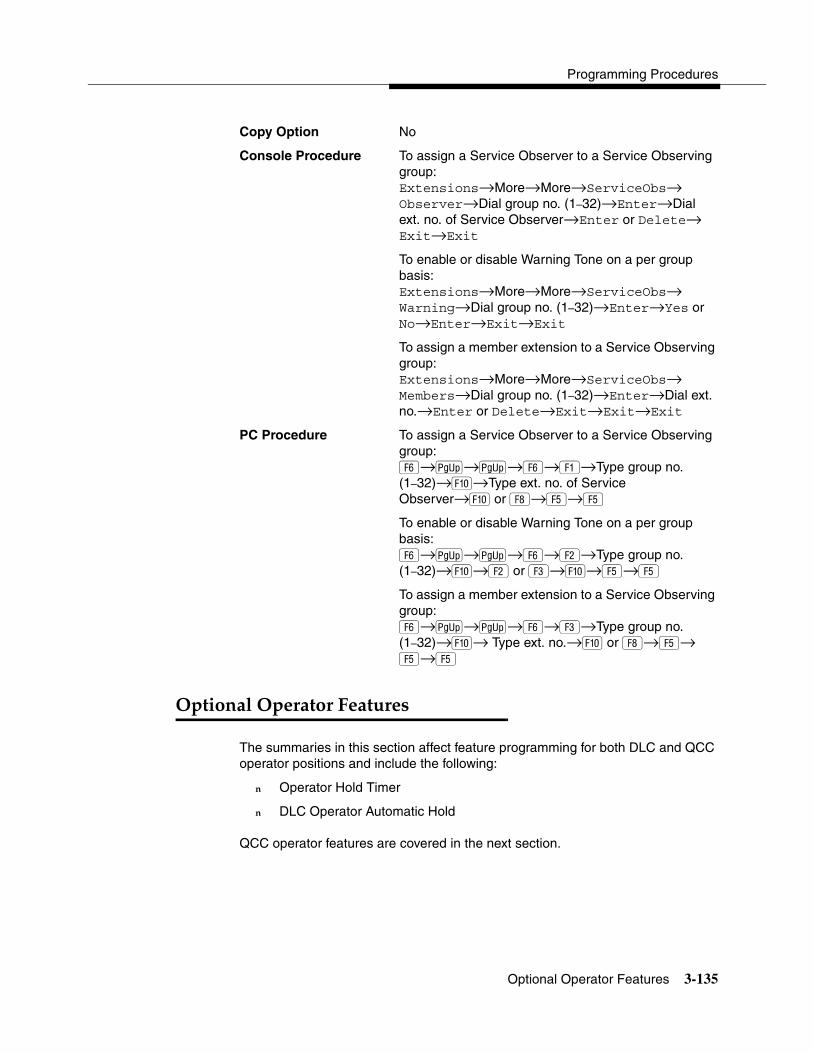
Programming Procedures
Optional Operator Features 3-135
Copy Option No
Console Procedure To assign a Service Observer to a Service Observing group:Extensions→More→More→ServiceObs→Observer→Dial group no. (1–32)→Enter→Dial ext. no. of Service Observer→Enter or Delete→ Exit→Exit
To enable or disable Warning Tone on a per group basis:Extensions→More→More→ServiceObs→Warning→Dial group no. (1–32)→Enter→Yes or No→Enter→Exit→Exit
To assign a member extension to a Service Observing group:Extensions→More→More→ServiceObs→Members→Dial group no. (1–32)→Enter→Dial ext. no.→Enter or Delete→Exit→Exit→Exit
PC Procedure To assign a Service Observer to a Service Observing group:�→�→�→�→�→Type group no. (1–32)→�→Type ext. no. of Service Observer→� or →�→�
To enable or disable Warning Tone on a per group basis:�→�→�→�→�→Type group no. (1–32)→�→� or �→�→�→�
To assign a member extension to a Service Observing group:�→�→�→�→�→Type group no. (1–32)→�→ Type ext. no.→� or →�→�→�
1��������1�� ��� �&���� �� 3
The summaries in this section affect feature programming for both DLC and QCC operator positions and include the following:
� Operator Hold Timer
� DLC Operator Automatic Hold
QCC operator features are covered in the next section.

System Programming
3-136 Optional Operator Features
1�� ��� �$��%����� 3
Use this procedure to set the length of the operator hold timer for all DLCs and QCCs. If the system operator does not pick up the call within the time programmed, an abbreviated ring reminds the operator that a call is being held.
This option cannot be programmed for individual operator positions.
����� ���1�� ��� �$��%����� 3
Programmable by System Manager
Mode All
Idle Condition Not required
Planning Form 6a, Optional Operator Features
Factory Setting 60 seconds
Valid Entries 10 to 255 seconds
Inspect No
Copy Option No
Console Procedure Operator→Hold Timer→Drop→Dial no. of seconds (10–255)→ Enter→Exit
PC Procedure �→�→ �+��→Type no. of seconds(10–255)→�→�
Although you can make selections from the screen (with the ListFeature option) to assign Ring and Voice buttons, the following procedure provides the programming codes to perform these functions. Using the codes speeds the button assignment process.
-���1�� ��� ����������$��% 3
Use this procedure to enable or disable the DLC Operator Automatic Hold feature for DLC operator positions. When this feature is enabled, it prevents accidental call disconnection.
����� ���-���1�� ��� ����������$��% 3
Programmable by System Manager
Mode All
Idle Condition Not required
Planning Form 6a, Optional Operator Features

Programming Procedures
QCC Optional Features 3-137
Factory Setting Disabled
Valid Entries Disabled, Enabled
Inspect No
Copy Option No
Console Procedure Operator→DLC Hold→Automatic Hold Enable or Automatic Hold Disable→Enter→Exit
PC Procedure �→�→� or �→�→�
9���1��������&���� �� 3
This section contains programming summaries for the following options for QCC operator positions:
� Hold Return
� Automatic Hold or Release
� Queue over Threshold
� Elevate Priority
� Calls-in-Queue Alert
� QCC Operator to Receive Call Types
� Call Type Queue Priority Level
� Message Center Operation
� Automatic or Manual Extended (Directed) Call Completion
� Return Ring
� Position Busy Backup
� Voice Announce
NOTE:These options are available in Hybrid/PBX mode only.
$��%�)��� � 3
Use this procedure to determine whether calls on hold are returned to the QCC queue or remain on hold, on the QCC operator console, after the hold timer has expired twice. After the hold timer expires the first time, the operator hears an abbreviated ring as a call-on-hold reminder. If another call is received at the same time that the hold timer expires, 10 seconds are added to the programmed operator hold timer interval for the first call. If the QCC operator does not pick up a
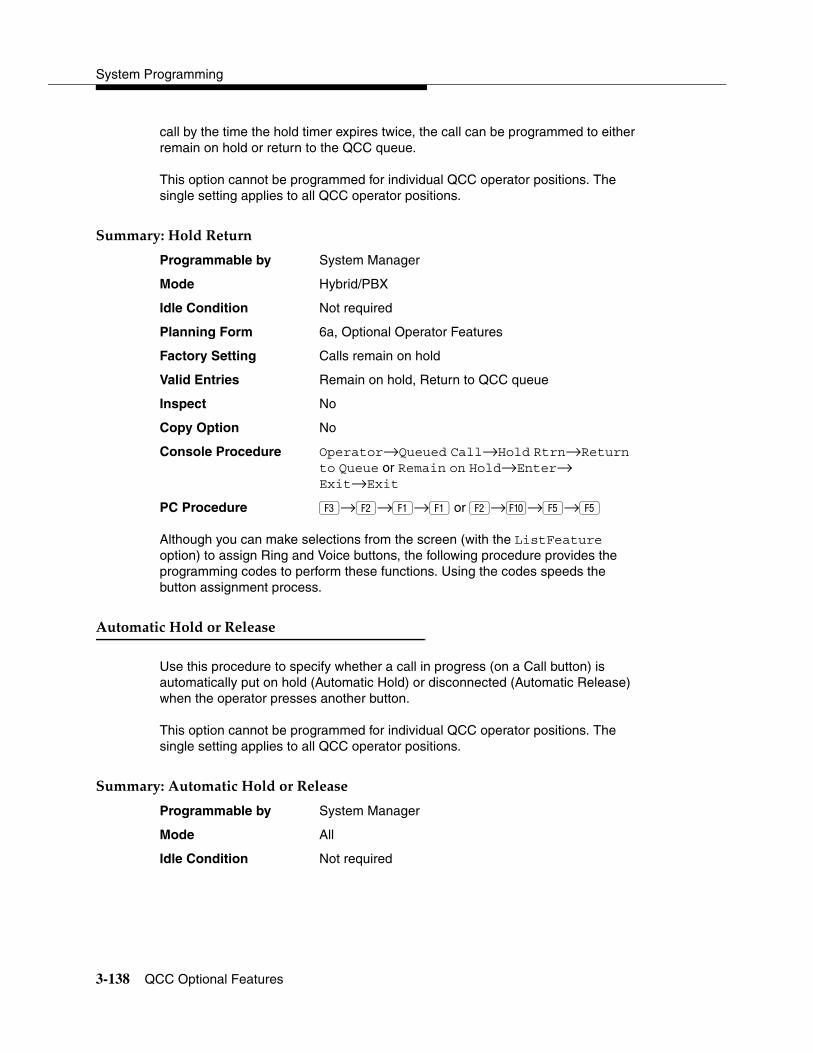
System Programming
3-138 QCC Optional Features
call by the time the hold timer expires twice, the call can be programmed to either remain on hold or return to the QCC queue.
This option cannot be programmed for individual QCC operator positions. The single setting applies to all QCC operator positions.
����� ���$��%�)��� � 3
Programmable by System Manager
Mode Hybrid/PBX
Idle Condition Not required
Planning Form 6a, Optional Operator Features
Factory Setting Calls remain on hold
Valid Entries Remain on hold, Return to QCC queue
Inspect No
Copy Option No
Console Procedure Operator→Queued Call→Hold Rtrn→Return to Queue or Remain on Hold→Enter→Exit→Exit
PC Procedure �→�→�→� or �→�→�→�
Although you can make selections from the screen (with the ListFeature option) to assign Ring and Voice buttons, the following procedure provides the programming codes to perform these functions. Using the codes speeds the button assignment process.
���������$��%�� �)������ 3
Use this procedure to specify whether a call in progress (on a Call button) is automatically put on hold (Automatic Hold) or disconnected (Automatic Release) when the operator presses another button.
This option cannot be programmed for individual QCC operator positions. The single setting applies to all QCC operator positions.
����� ������������$��%�� �)������ 3
Programmable by System Manager
Mode All
Idle Condition Not required
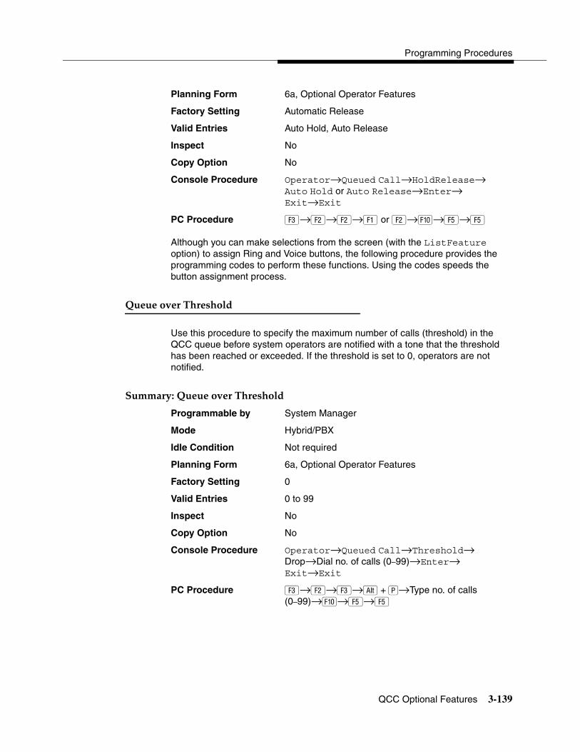
Programming Procedures
QCC Optional Features 3-139
Planning Form 6a, Optional Operator Features
Factory Setting Automatic Release
Valid Entries Auto Hold, Auto Release
Inspect No
Copy Option No
Console Procedure Operator→Queued Call→HoldRelease→Auto Hold or Auto Release→Enter→Exit→Exit
PC Procedure �→�→�→� or �→�→�→�
Although you can make selections from the screen (with the ListFeature option) to assign Ring and Voice buttons, the following procedure provides the programming codes to perform these functions. Using the codes speeds the button assignment process.
9������5� ��� �����% 3
Use this procedure to specify the maximum number of calls (threshold) in the QCC queue before system operators are notified with a tone that the threshold has been reached or exceeded. If the threshold is set to 0, operators are not notified.
����� ���9������5� ��� �����% 3
Programmable by System Manager
Mode Hybrid/PBX
Idle Condition Not required
Planning Form 6a, Optional Operator Features
Factory Setting 0
Valid Entries 0 to 99
Inspect No
Copy Option No
Console Procedure Operator→Queued Call→Threshold→Drop→Dial no. of calls (0–99)→Enter→Exit→Exit
PC Procedure �→�→�→ �+��→Type no. of calls (0–99)→�→�→�

System Programming
3-140 QCC Optional Features
Although you can make selections from the screen (with the ListFeature option) to assign Ring and Voice buttons, the following procedure provides the programming codes to perform these functions. Using the codes speeds the button assignment process.
���5����� �� ��� 3
Use this procedure to specify the length of time before calls waiting in the QCC queue are automatically reprioritized to a higher level. If priority is set to 0, calls are not prioritized.
����� ������5����� �� ��� 3
Programmable by System Manager
Mode Hybrid/PBX
Idle Condition Not required
Planning Form Form 6a, Optional Operator Features
Factory Setting 0 seconds
Valid Entries 0 and 5 to 30 seconds
Inspect No
Copy Option No
Console Procedure Operator→QueuedCall→ElvatePrior→ Drop→Dial no. of seconds (0 and 5–30)→ Enter→Exit→Exit
PC Procedure �→�→�→ �+��→Type no. of seconds (0 and 5–30)→�→�→�
Although you can make selections from the screen (with the ListFeature option) to assign Ring and Voice buttons, the following procedure provides the programming codes to perform these functions. Using the codes speeds the button assignment process.
�����!��!9������� � 3
Use this procedure to specify whether each QCC operator is notified (with a single beep) when a new call enters the QCC queue.

Programming Procedures
QCC Optional Features 3-141
����� ��������!��!9������� � 3
Programmable by System Manager
Mode Hybrid/PBX
Idle Condition Not required
Planning Form 6a, Optional Operator Features
Factory Setting Disable
Valid Entries Enable, Disable
Inspect Yes
Copy Option No
Console Procedure Operator→Queued Call→InQue Alert→Dial ext. no.→Enter→InQue Alert Enable or InQue Alert Disable→Enter→Exit→Exit
PC Procedure �→�→�→Type ext. no.→�→� or �→�→�→�
Although you can make selections from the screen (with the ListFeature option) to assign Ring and Voice buttons, the following procedure provides the programming codes to perform these functions. Using the codes speeds the button assignment process.
9���1�� ��� ����)����5������������ 3
Use this procedure to specify which QCC operators receive the following types of calls:
� Dial 0 calls (internal calls to the system operator)
� DID calls to invalid destinations (unassigned extension numbers)
� Calls to the Listed Directory Number (extension for the QCC queue)
� Calls programmed to return to the QCC queue (returning from directing, camped-on, held calls, and operator parked calls)
� Group Coverage calls
� Forward/Follow Me calls
The QCC queue can be a receiver for the maximum number of coverage groups (30).
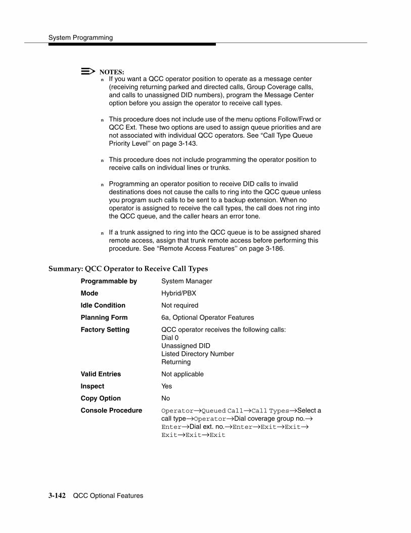
System Programming
3-142 QCC Optional Features
NOTES:� If you want a QCC operator position to operate as a message center
(receiving returning parked and directed calls, Group Coverage calls, and calls to unassigned DID numbers), program the Message Center option before you assign the operator to receive call types.
� This procedure does not include use of the menu options Follow/Frwd or QCC Ext. These two options are used to assign queue priorities and are not associated with individual QCC operators. See ‘‘Call Type Queue Priority Level’’ on page 3-143.
� This procedure does not include programming the operator position to receive calls on individual lines or trunks.
� Programming an operator position to receive DID calls to invalid destinations does not cause the calls to ring into the QCC queue unless you program such calls to be sent to a backup extension. When no operator is assigned to receive the call types, the call does not ring into the QCC queue, and the caller hears an error tone.
� If a trunk assigned to ring into the QCC queue is to be assigned shared remote access, assign that trunk remote access before performing this procedure. See ‘‘Remote Access Features’’ on page 3-186.
����� ���9���1�� ��� ����)����5������������ 3
Programmable by System Manager
Mode Hybrid/PBX
Idle Condition Not required
Planning Form 6a, Optional Operator Features
Factory Setting QCC operator receives the following calls:Dial 0Unassigned DIDListed Directory NumberReturning
Valid Entries Not applicable
Inspect Yes
Copy Option No
Console Procedure Operator→Queued Call→Call Types→Select a call type→Operator→Dial coverage group no.→Enter→Dial ext. no.→Enter→Exit→Exit→Exit→Exit→Exit
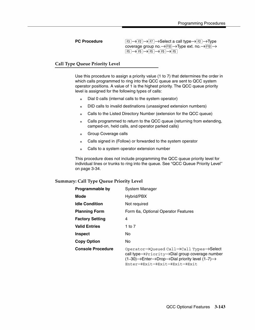
Programming Procedures
QCC Optional Features 3-143
PC Procedure �→�→→Select a call type→�→Type coverage group no.→�→Type ext. no.→�→�→�→�→�→�
����������9������ �� ������5�� 3
Use this procedure to assign a priority value (1 to 7) that determines the order in which calls programmed to ring into the QCC queue are sent to QCC system operator positions. A value of 1 is the highest priority. The QCC queue priority level is assigned for the following types of calls:
� Dial 0 calls (internal calls to the system operator)
� DID calls to invalid destinations (unassigned extension numbers)
� Calls to the Listed Directory Number (extension for the QCC queue)
� Calls programmed to return to the QCC queue (returning from extending, camped-on, held calls, and operator parked calls)
� Group Coverage calls
� Calls signed in (Follow) or forwarded to the system operator
� Calls to a system operator extension number
This procedure does not include programming the QCC queue priority level for individual lines or trunks to ring into the queue. See ‘‘QCC Queue Priority Level’’ on page 3-34.
����� �������������9������ �� ������5�� 3
Programmable by System Manager
Mode Hybrid/PBX
Idle Condition Not required
Planning Form Form 6a, Optional Operator Features
Factory Setting 4
Valid Entries 1 to 7
Inspect No
Copy Option No
Console Procedure Operator→Queued Call→Call Types→Select call type→Priority→Dial group coverage number (1–30)→Enter→Drop→Dial priority level (1–7)→ Enter→Exit→Exit→Exit→Exit
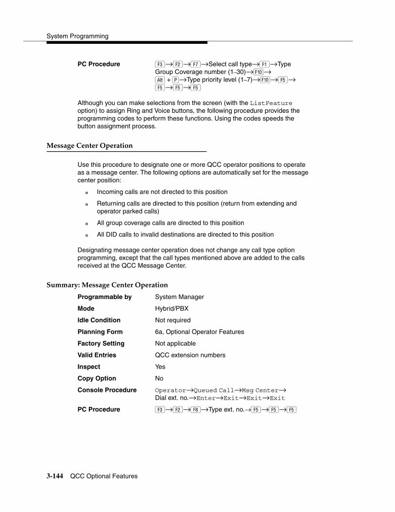
System Programming
3-144 QCC Optional Features
PC Procedure �→�→→Select call type→�→Type Group Coverage number (1–30)→�→ �+��→Type priority level (1–7)→�→�→ �→�→�
Although you can make selections from the screen (with the ListFeature option) to assign Ring and Voice buttons, the following procedure provides the programming codes to perform these functions. Using the codes speeds the button assignment process.
������������ �1�� ����� 3
Use this procedure to designate one or more QCC operator positions to operate as a message center. The following options are automatically set for the message center position:
� Incoming calls are not directed to this position
� Returning calls are directed to this position (return from extending and operator parked calls)
� All group coverage calls are directed to this position
� All DID calls to invalid destinations are directed to this position
Designating message center operation does not change any call type option programming, except that the call types mentioned above are added to the calls received at the QCC Message Center.
����� ��������������� �1�� ����� 3
Programmable by System Manager
Mode Hybrid/PBX
Idle Condition Not required
Planning Form 6a, Optional Operator Features
Factory Setting Not applicable
Valid Entries QCC extension numbers
Inspect Yes
Copy Option No
Console Procedure Operator→Queued Call→Msg Center→Dial ext. no.→Enter→Exit→Exit→Exit
PC Procedure �→�→→Type ext. no.→�→�→�
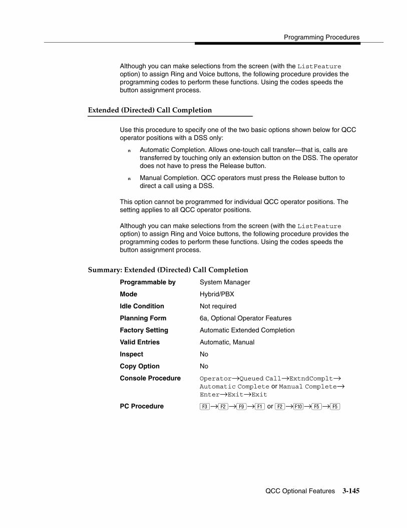
Programming Procedures
QCC Optional Features 3-145
Although you can make selections from the screen (with the ListFeature option) to assign Ring and Voice buttons, the following procedure provides the programming codes to perform these functions. Using the codes speeds the button assignment process.
�����%�%�"-� ����%#���������������� 3
Use this procedure to specify one of the two basic options shown below for QCC operator positions with a DSS only:
� Automatic Completion. Allows one-touch call transfer—that is, calls are transferred by touching only an extension button on the DSS. The operator does not have to press the Release button.
� Manual Completion. QCC operators must press the Release button to direct a call using a DSS.
This option cannot be programmed for individual QCC operator positions. The setting applies to all QCC operator positions.
Although you can make selections from the screen (with the ListFeature option) to assign Ring and Voice buttons, the following procedure provides the programming codes to perform these functions. Using the codes speeds the button assignment process.
����� ��������%�%�"-� ����%#���������������� 3
Programmable by System Manager
Mode Hybrid/PBX
Idle Condition Not required
Planning Form 6a, Optional Operator Features
Factory Setting Automatic Extended Completion
Valid Entries Automatic, Manual
Inspect No
Copy Option No
Console Procedure Operator→Queued Call→ExtndComplt→Automatic Complete or Manual Complete→Enter→Exit→Exit
PC Procedure �→�→�→� or �→�→�→�
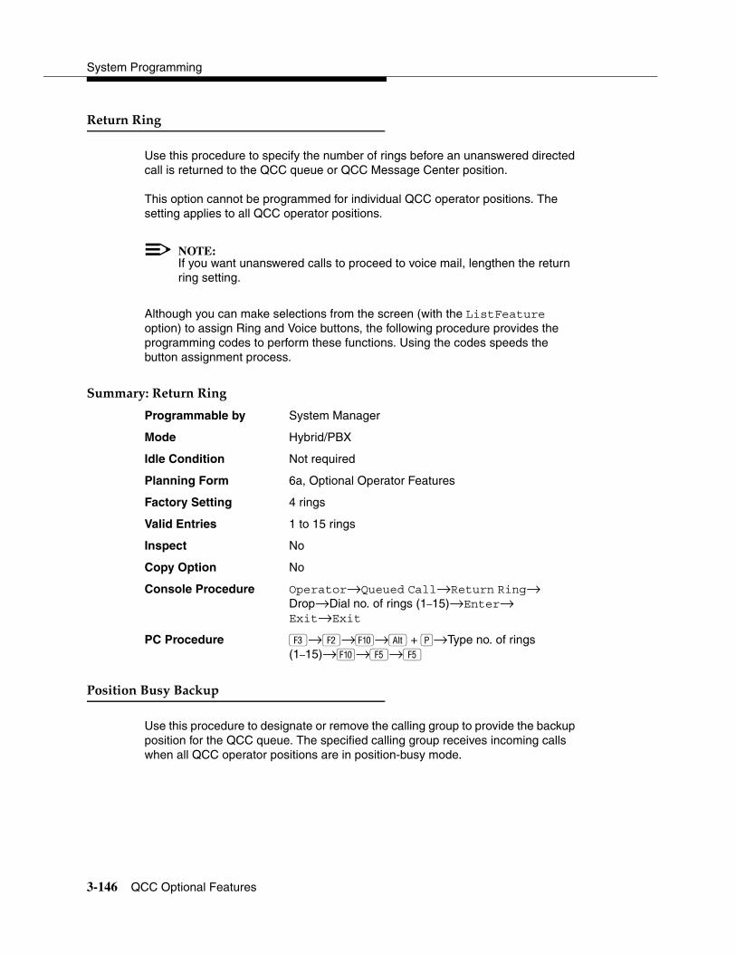
System Programming
3-146 QCC Optional Features
)��� ��)�� 3
Use this procedure to specify the number of rings before an unanswered directed call is returned to the QCC queue or QCC Message Center position.
This option cannot be programmed for individual QCC operator positions. The setting applies to all QCC operator positions.
NOTE:If you want unanswered calls to proceed to voice mail, lengthen the return ring setting.
Although you can make selections from the screen (with the ListFeature option) to assign Ring and Voice buttons, the following procedure provides the programming codes to perform these functions. Using the codes speeds the button assignment process.
����� ���)��� ��)�� 3
Programmable by System Manager
Mode Hybrid/PBX
Idle Condition Not required
Planning Form 6a, Optional Operator Features
Factory Setting 4 rings
Valid Entries 1 to 15 rings
Inspect No
Copy Option No
Console Procedure Operator→Queued Call→Return Ring→Drop→Dial no. of rings (1–15)→Enter→ Exit→Exit
PC Procedure �→�→�→ �+��→Type no. of rings(1–15)→�→�→�
�������������������� 3
Use this procedure to designate or remove the calling group to provide the backup position for the QCC queue. The specified calling group receives incoming calls when all QCC operator positions are in position-busy mode.

Programming Procedures
QCC Optional Features 3-147
Position Busy Backup is programmed for the QCC queue rather than for individual QCC operator positions. The calling group designated as the QCC queue backup serves as the backup for the Remote Access feature and as backup when the QCC is being used as the system programming console.
Only one Position Busy Backup can be programmed per system.
����� ����������������������� 3
Programmable by System Manager
Mode Hybrid/PBX
Idle Condition Not required
Planning Form 6a, Optional Operator Features
Factory Setting No backup
Valid Entries Calling group number
Inspect No
Copy Option No
Console Procedure Operator→Queued Call→More→QCC Backup→Drop→Dial ext. number→Enter or Delete→Exit→Exit
PC Procedure �→�→�→�→ +��→Type ext. number→� or →�→�
(������������ 3
Use this procedure to enable or disable Voice Announce for the QCC. Voice Announce is available only on a QCC in Release 4.0 and later.
When Voice Announce is enabled, every QCC in the system has one Voice Announce Call button, the Call 5 (Ring/Voice) button. All Intercom calls that originate from a QCC Call 5 (Ring/Voice) button are delivered as Voice Announce calls.
When Voice Announce is disabled, all Intercom calls originating at the QCC Call buttons are Intercom Ringing calls.
����� ���(������������ 3
Programmable by System Manager
Mode Hybrid/PBX
Idle Condition Not required
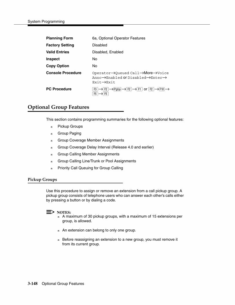
System Programming
3-148 Optional Group Features
Planning Form 6a, Optional Operator Features
Factory Setting Disabled
Valid Entries Disabled, Enabled
Inspect No
Copy Option No
Console Procedure Operator→Queued Call→More→Voice Annc→Enabled or Disabled→Enter→Exit→Exit
PC Procedure �→�→�→�→� or �→�→�→�
1��������8 ����&���� �� 3
This section contains programming summaries for the following optional features:
� Pickup Groups
� Group Paging
� Group Coverage Member Assignments
� Group Coverage Delay Interval (Release 4.0 and earlier)
� Group Calling Member Assignments
� Group Calling Line/Trunk or Pool Assignments
� Priority Call Queuing for Group Calling
�������8 ���� 3
Use this procedure to assign or remove an extension from a call pickup group. A pickup group consists of telephone users who can answer each other’s calls either by pressing a button or by dialing a code.
NOTES:� A maximum of 30 pickup groups, with a maximum of 15 extensions per
group, is allowed.
� An extension can belong to only one group.
� Before reassigning an extension to a new group, you must remove it from its current group.

Programming Procedures
Optional Group Features 3-149
����� ����������8 ���� 3
Programmable by System Manager
Mode All
Idle Condition Not required
Planning Form 7a, Pickup Groups
Factory Setting Not applicable
Valid Entries Pickup group number, extension number
Inspect Yes
Copy Option No
Console Procedure Extensions→Call Pickup→Dial pickup group no.→Enter→Dial ext. no.→Enter→Enter→ Exit→Exit
PC Procedure �→�→Type pickup group no.→�→Type ext. no.→�→�→�
8 �������� 3
Use this procedure to assign or remove an extension from a paging group. A paging group consists of telephone users who hear common announcements over the telephone speakerphone. Only MLX telephones and analog multiline telephones with speakerphones can be members of a paging group.
A maximum of six paging groups with a maximum of 10 extensions per group is allowed. A seventh paging group, called the Page All group, is not limited and includes all telephones connected to the system. Extensions cannot be added to or removed from the Page All group.
To reassign an extension to a new paging group, just assign it; the extension is automatically removed from its old paging group.
����� ���8 �������� 3
Programmable by System Manager
Mode All
Idle Condition Not required
Planning Form 7b, Group Paging
Factory Setting Not applicable
Valid Entries Extension number

System Programming
3-150 Optional Group Features
Inspect Yes
Copy Option No
Console Procedure Extensions→More→Group Page→Dial paging group no.→Enter→Dial ext. no.→Enter→Exit→Exit
PC Procedure �→�→�→Type paging group no.→�→Type ext. no.→�→�→�
Although you can make selections from the screen (with the ListFeature option) to assign Ring and Voice buttons, the following procedure provides the programming codes to perform these functions. Using the codes speeds the button assignment process.
8 ������5� ������'� ���������� 3
Use this procedure to assign or remove an extension from a coverage group. A coverage group is a group of senders. Coverage is an arrangement in which calls from a group of senders are redirected to one or more receivers.
NOTE:This procedure assigns senders. Before you begin, make certain that the receivers for the coverage group are also programmed. Receivers can be assigned through individual or centralized telephone programming. You can also use the Integrated Solution III/IV feature, Integrated Administration, to assign coverage receivers. See Chapter 4, ‘‘Centralized Telephone Programming,” for information about the appropriate centralized programming procedure.
A maximum of 30 coverage groups are allowed, each with an unlimited number of members. Up to eight receivers can be assigned per coverage group.
An extension can be a sender in only one group; it can be a receiver for more than one coverage group. A calling group can be assigned as a receiver for a coverage group (see ‘‘Group Coverage Receiver’’ on page 3-159). In Hybrid/PBX mode only, the QCC queue can be a receiver for up to 30 coverage groups. See ‘‘QCC Operator to Receive Calls’’ on page 3-35.
If the sender’s extension has one or more personal lines assigned, the sender can be assigned as the principal user so that calls received on the personal line are sent to receivers programmed for Individual or Group Coverage. See ‘‘Principal User for Personal Line’’ on page 3-33.
To reassign an extension to a new coverage group, just make the assignment; the extension is automatically removed from its old group.

Programming Procedures
Optional Group Features 3-151
����� ���8 ������5� ������'� ���������� 3
Programmable by System Manager
Mode All
Idle Condition Not required
Planning Form 7c, Group Coverage
Factory Setting Not applicable
Valid Entries Extension numbers
Inspect Yes
Copy Option No
Console Procedure Extensions→More→Group Cover→Dial group no. (1–30)→Enter→Dial ext. no.→Enter→ Exit→Exit
PC Procedure �→�→�→Type group no. (1–30)→ �→Type ext. no.→�→�→�
8 ������5� ���-��������� 5�� 3
Use this procedure to specify the number of rings before a call is sent to group coverage receivers.
NOTE:This setting is for Release 4.0 and earlier systems. Use Group Coverage Ring Delay for Release 4.1 and later systems.
Although you can make selections from the screen (with the ListFeature option) to assign Ring and Voice buttons, the following procedure provides the programming codes to perform these functions. Using the codes speeds the button assignment process.
����� ���8 ������5� ���-��������� 5�� 3
Programmable by System Manager
Mode All
Idle Condition Not required
Planning Form 7c, Group Coverage
Factory Setting Not applicable
Valid Entries Extension numbers
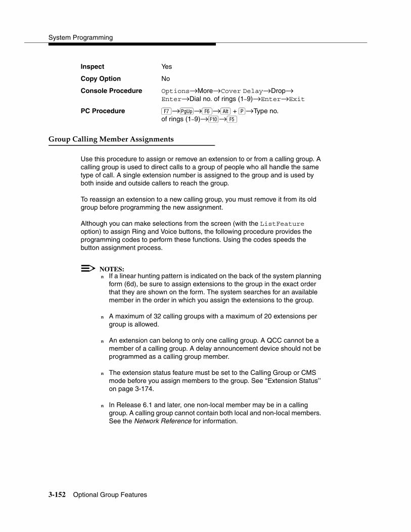
System Programming
3-152 Optional Group Features
Inspect Yes
Copy Option No
Console Procedure Options→More→Cover Delay→Drop→Enter→Dial no. of rings (1–9)→Enter→Exit
PC Procedure →�→�→ +��→Type no. of rings (1–9)→�→�
8 ��������������'� ���������� 3
Use this procedure to assign or remove an extension to or from a calling group. A calling group is used to direct calls to a group of people who all handle the same type of call. A single extension number is assigned to the group and is used by both inside and outside callers to reach the group.
To reassign an extension to a new calling group, you must remove it from its old group before programming the new assignment.
Although you can make selections from the screen (with the ListFeature option) to assign Ring and Voice buttons, the following procedure provides the programming codes to perform these functions. Using the codes speeds the button assignment process.
NOTES:� If a linear hunting pattern is indicated on the back of the system planning
form (6d), be sure to assign extensions to the group in the exact order that they are shown on the form. The system searches for an available member in the order in which you assign the extensions to the group.
� A maximum of 32 calling groups with a maximum of 20 extensions per group is allowed.
� An extension can belong to only one calling group. A QCC cannot be a member of a calling group. A delay announcement device should not be programmed as a calling group member.
� The extension status feature must be set to the Calling Group or CMS mode before you assign members to the group. See ‘‘Extension Status’’ on page 3-174.
� In Release 6.1 and later, one non-local member may be in a calling group. A calling group cannot contain both local and non-local members. See the Network Reference for information.

Programming Procedures
Optional Group Features 3-153
����� ���8 ��������������'� ���������� 3
Programmable by System Manager
Mode All
Idle Condition Not required
Planning Form 7c, Group Coverage
Factory Setting Not applicable
Valid Entries Extension numbers
Inspect Yes
Copy Option No
Console Procedure Extensions→More→Grp Calling→Members→Dial calling group ext. no.→Enter→Dial ext. no.→Enter→Exit→Exit→Exit
PC Procedure �→�→�→�→Type calling group ext. no.→�→Type ext. no.→�→�→�→�
Although you can make selections from the screen (with the ListFeature option) to assign Ring and Voice buttons, the following procedure provides the programming codes to perform these functions. Using the codes speeds the button assignment process.
8 ����������������� ����� ��������������� 3
Use this procedure to assign or remove lines, trunks, or pools (Hybrid/PBX only) that ring directly into a calling group.
Incoming calls on each line/trunk or pool can be directed to only one calling group.
To reassign a line/trunk or pool to a new calling group, you must remove it from its old group before making the new assignment.
����� ���8 ����������������� ����� ��������������� 3
Programmable by System Manager
Mode All
Idle Condition Not required
Planning Form 7d, Group Calling
Factory Setting Not applicable
Valid Entries Line, trunk, or pool number

System Programming
3-154 Optional Group Features
Inspect Yes
Copy Option No
Console Procedure Extensions→More→Grp Calling→Line/Pool→Dial calling group ext. no.→Enter→Dial line/trunk no.→Enter→Exit→Exit→Exit
PC Procedure �→�→�→�→Type calling group ext. no.→�→Type line/trunk no.→�→�→�→�
� �� ���������9����� 3
Use this procedure to establish a supportive relationship between calling groups. Calls that arrive in one calling group (a home group) can be processed by another calling group (a support group) when no one from the first calling group is available to answer the call.
A calling group can be assigned a priority level between 1 (highest priority) and 32 (lowest priority) and then designated as a support group for a home group. There can be only one support group per home group. Each support group can support up to 31 home groups.
����� ���� �� ���������9����� 3
Programmable by System Manager
Mode All
Idle Condition Not Required
Planning Form 7d, Group Calling
Factory Setting 16
Valid Entries Priority Level (1 to 32)
Inspect Yes
Copy Option No
Console Procedure Extensions→More→Grp Calling→More→ Priority→Enter extension number of group→ Enter→Enter Group Priority (1–32)→(To program the next group, select Next)→Enter→Exit→ Support→Enter extension number of group→ Enter→Enter Support Group→(To program the next group, select Next)→Enter→Exit→Exit→Exit
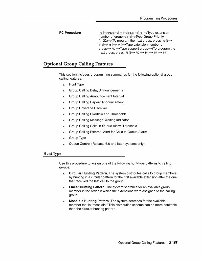
Programming Procedures
Optional Group Calling Features 3-155
PC Procedure �→�→�→�→�→Type extension number of group→�→Type Group Priority (1–32)→(To program the next group, press �)→ �→�→�→Type extension number of group→�→Type support group→(To program the next group, press �)→�→�→�→�
1��������8 �����������&���� �� 3
This section includes programming summaries for the following optional group calling features:
� Hunt Type
� Group Calling Delay Announcements
� Group Calling Announcement Interval
� Group Calling Repeat Announcement
� Group Coverage Receiver
� Group Calling Overflow and Thresholds
� Group Calling Message-Waiting Indicator
� Group Calling Calls-in-Queue Alarm Threshold
� Group Calling External Alert for Calls-in-Queue Alarm
� Group Type
� Queue Control (Release 6.0 and later systems only)
$�������� 3
Use this procedure to assign one of the following hunt-type patterns to calling groups:
� Circular Hunting Pattern. The system distributes calls to group members by hunting in a circular pattern for the first available extension after the one that received the last call to the group.
� Linear Hunting Pattern. The system searches for an available group member in the order in which the extensions were assigned to the calling group.
� Most Idle Hunting Pattern. The system searches for the available member that is “most idle.” This distribution scheme can be more equitable than the circular hunting pattern.
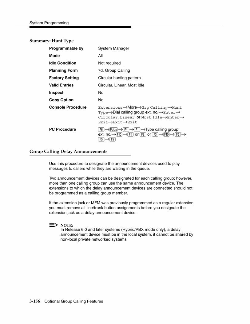
System Programming
3-156 Optional Group Calling Features
����� ���$�������� 3
Programmable by System Manager
Mode All
Idle Condition Not required
Planning Form 7d, Group Calling
Factory Setting Circular hunting pattern
Valid Entries Circular, Linear, Most Idle
Inspect No
Copy Option No
Console Procedure Extensions→More→Grp Calling→Hunt Type→Dial calling group ext. no.→Enter→Circular, Linear, or Most Idle→Enter→Exit→Exit→Exit
PC Procedure �→�→�→�→Type calling group ext. no.→�→� or � or �→�→�→�→�
8 �����������-����������������� 3
Use this procedure to designate the announcement devices used to play messages to callers while they are waiting in the queue.
Two announcement devices can be designated for each calling group; however, more than one calling group can use the same announcement device. The extensions to which the delay announcement devices are connected should not be programmed as a calling group member.
If the extension jack or MFM was previously programmed as a regular extension, you must remove all line/trunk button assignments before you designate the extension jack as a delay announcement device.
NOTE:In Release 6.0 and later systems (Hybrid/PBX mode only), a delay announcement device must be in the local system, it cannot be shared by non-local private networked systems.

Programming Procedures
Optional Group Calling Features 3-157
����� ���8 �����������-���������������� 3
Programmable by System Manager
Mode All
Idle Condition Not required
Planning Form 7d, Group Calling
Factory Setting No delay announcement devices are assigned
Valid Entries Primary Announcement, Secondary Announcement
Inspect No
Copy Option No
Console Procedure Extensions→More→Grp Calling→DelayAnnce→Dial calling group ext. no.→Enter→Primary Announcement or Secondary Announcement→Enter extension number of announcement device→Enter→Exit→Exit→Exit
PC Procedure �→�→�→�→Type calling group ext. no.→ �→��or �→Type ext. no. of announcement device→�→�→�
8 ��������������������������� 5�� 3
Use this procedure to set the delay before the secondary announcement is played and/or repeated.
����� ���8 ��������������������������� 5��3
Programmable by System Manager
Mode All
Idle Condition Not required
Planning Form 7d, Group Calling
Factory Setting 0 (disabled)
Valid Entries 0–900 seconds
Inspect No
Copy Option No

System Programming
3-158 Optional Group Calling Features
Console Procedure Extensions→More→Grp Calling→DelayAnnce→ Dial calling group ext. no.→Announcement Interval→Enter the Announcement Interval (0–900)→Enter→ Exit→Exit
PC Procedure �→�→�→�→Type calling group ext. no.→�→Type the Announcement Interval(0–900)→ �→�→�
8 �����������)����������������� 3
Use this procedure to set the secondary announcement to repeat after the Announcement Interval.
����� ���8 �����������)����������������� 3
Programmable by System Manager
Mode All
Idle Condition Not required
Planning Form 7d, Group Calling
Factory Setting No repeat
Valid Entries Yes, No
Inspect No
Copy Option No
Console Procedure Extensions→More→Grp Calling→DelayAnnce→Dial calling group ext. no.→Enter→Repeat Announcement→Yes or No→Enter→Exit→Exit
PC Procedure �→�→�→�→�→Type calling group ext. no.→��or���→�→�→�
Although you can make selections from the screen (with the ListFeature option) to assign Ring and Voice buttons, the following procedure provides the programming codes to perform these functions. Using the codes speeds the button assignment process.

Programming Procedures
Optional Group Calling Features 3-159
8 ������5� ���)����5� 3
Use this procedure to assign or remove a calling group as a receiver for a coverage group.
Calling group member assignments must be made before you assign the group as a receiver for a coverage group.
����� ���8 ������5� ���)����5� 3
Programmable by System Manager
Mode All
Idle Condition Not required
Planning Form 7c, Group Coverage
Factory Setting Not applicable
Valid Entries Group numbers
Inspect Yes
Copy Option No
Console Procedure Extensions→More→Grp Calling→Grp Coverage→Dial calling group ext. no.→Enter→Dial coverage group no.→Enter→Exit→Exit→Exit
PC Procedure �→�→�→�→Type calling group ext. no.→�→Type coverage group no.→�→�→�→�
8 �����������15� 6�� ���%��� �����%� 3
Use this procedure to designate either another calling group or the QCC queue (Hybrid/PBX only) to receive overflow calls. This procedure also specifies overflow threshold and methods.
Call overflow occurs in one of the three following ways:
� The number of calls waiting in the queue for a calling group is equal to or greater than the programmed threshold (overflow threshold).
� The time that a call has spent in the queue exceeds the programmed timeout value (overflow threshold time).
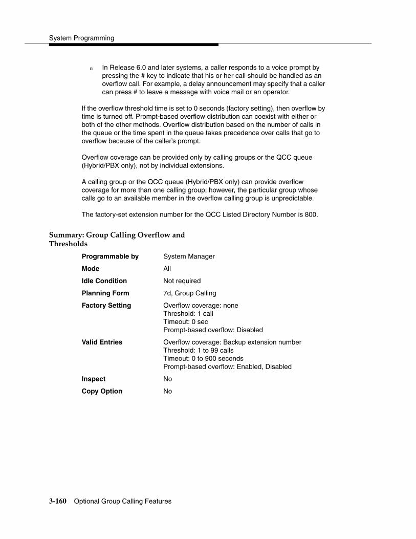
System Programming
3-160 Optional Group Calling Features
� In Release 6.0 and later systems, a caller responds to a voice prompt by pressing the # key to indicate that his or her call should be handled as an overflow call. For example, a delay announcement may specify that a caller can press # to leave a message with voice mail or an operator.
If the overflow threshold time is set to 0 seconds (factory setting), then overflow by time is turned off. Prompt-based overflow distribution can coexist with either or both of the other methods. Overflow distribution based on the number of calls in the queue or the time spent in the queue takes precedence over calls that go to overflow because of the caller’s prompt.
Overflow coverage can be provided only by calling groups or the QCC queue (Hybrid/PBX only), not by individual extensions.
A calling group or the QCC queue (Hybrid/PBX only) can provide overflow coverage for more than one calling group; however, the particular group whose calls go to an available member in the overflow calling group is unpredictable.
The factory-set extension number for the QCC Listed Directory Number is 800.
����� ���8 �����������15� 6�� ���%��� �����%� 3
Programmable by System Manager
Mode All
Idle Condition Not required
Planning Form 7d, Group Calling
Factory Setting Overflow coverage: noneThreshold: 1 callTimeout: 0 secPrompt-based overflow: Disabled
Valid Entries Overflow coverage: Backup extension numberThreshold: 1 to 99 callsTimeout: 0 to 900 secondsPrompt-based overflow: Enabled, Disabled
Inspect No
Copy Option No
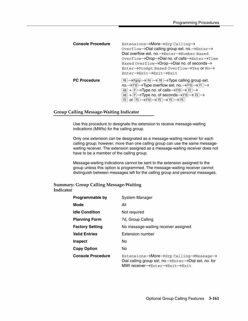
Programming Procedures
Optional Group Calling Features 3-161
Console Procedure Extensions→More→Grp Calling→Overflow→Dial calling group ext. no.→Enter→Dial overflow ext. no.→Enter→Number Based Overflow→Drop→Dial no. of calls→Enter→Time Based Overflow→Drop→Dial no. of seconds→Enter→Prompt Based Overflow→Yes or No→Enter→Exit→Exit→Exit
PC Procedure �→�→�→→Type calling group ext. no.→�→Type overflow ext. no.→�→�→ + �→Type no. of calls→�→�→ +��→Type no. of seconds→�→�→� or �→�→�→�→�
8 �����������������!:��������%����� 3
Use this procedure to designate the extension to receive message-waiting indications (MWIs) for the calling group.
Only one extension can be designated as a message-waiting receiver for each calling group; however, more than one calling group can use the same message-waiting receiver. The extension assigned as a message-waiting receiver does not have to be a member of the calling group.
Message-waiting indications cannot be sent to the extension assigned to the group unless this option is programmed. The message-waiting receiver cannot distinguish between messages left for the calling group and personal messages.
����� ���8 �����������������!:��������%����� 3
Programmable by System Manager
Mode All
Idle Condition Not required
Planning Form 7d, Group Calling
Factory Setting No message-waiting receiver assigned
Valid Entries Extension number
Inspect No
Copy Option No
Console Procedure Extensions→More→Grp Calling→Message→Dial calling group ext. no.→Enter→Dial ext. no. for MWI receiver→Enter→Exit→Exit
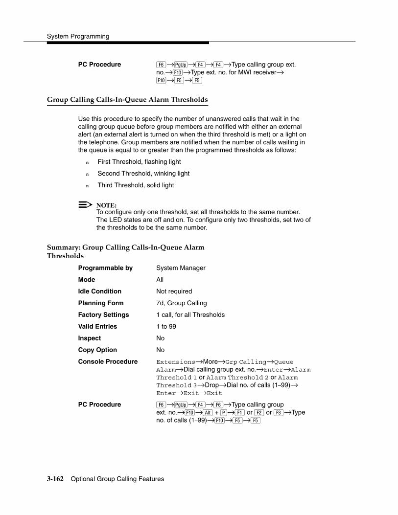
System Programming
3-162 Optional Group Calling Features
PC Procedure �→�→�→�→Type calling group ext. no.→�→Type ext. no. for MWI receiver→�→�→�
8 ����������������!��!9������� ���� �����%� 3
Use this procedure to specify the number of unanswered calls that wait in the calling group queue before group members are notified with either an external alert (an external alert is turned on when the third threshold is met) or a light on the telephone. Group members are notified when the number of calls waiting in the queue is equal to or greater than the programmed thresholds as follows:
� First Threshold, flashing light
� Second Threshold, winking light
� Third Threshold, solid light
NOTE:To configure only one threshold, set all thresholds to the same number. The LED states are off and on. To configure only two thresholds, set two of the thresholds to be the same number.
����� ���8 ����������������!��!9������� ���� �����%� 3
Programmable by System Manager
Mode All
Idle Condition Not required
Planning Form 7d, Group Calling
Factory Settings 1 call, for all Thresholds
Valid Entries 1 to 99
Inspect No
Copy Option No
Console Procedure Extensions→More→Grp Calling→Queue Alarm→Dial calling group ext. no.→Enter→Alarm Threshold 1 or Alarm Threshold 2 or Alarm Threshold 3→Drop→Dial no. of calls (1–99)→ Enter→Exit→Exit
PC Procedure �→�→�→�→Type calling groupext. no.→�→ +��→��or���or �→Type no. of calls (1–99)→�→�→�
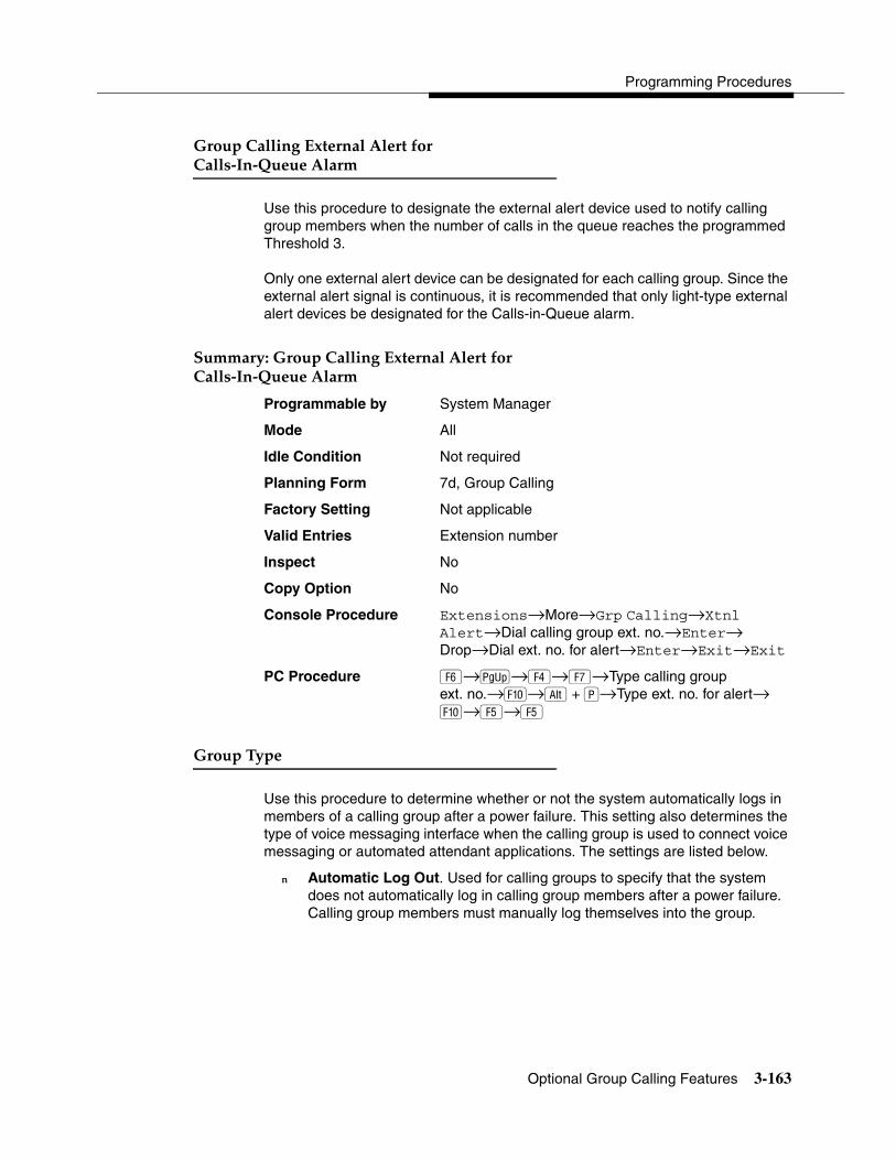
Programming Procedures
Optional Group Calling Features 3-163
8 ��������������� ������ ��6� ������!��!9���� �� � 3
Use this procedure to designate the external alert device used to notify calling group members when the number of calls in the queue reaches the programmed Threshold 3.
Only one external alert device can be designated for each calling group. Since the external alert signal is continuous, it is recommended that only light-type external alert devices be designated for the Calls-in-Queue alarm.
����� ���8 ��������������� ������ ��6� ������!��!9������� � 3
Programmable by System Manager
Mode All
Idle Condition Not required
Planning Form 7d, Group Calling
Factory Setting Not applicable
Valid Entries Extension number
Inspect No
Copy Option No
Console Procedure Extensions→More→Grp Calling→Xtnl Alert→Dial calling group ext. no.→Enter→Drop→Dial ext. no. for alert→Enter→Exit→Exit
PC Procedure �→�→�→→Type calling group ext. no.→�→ +��→Type ext. no. for alert→�→�→�
8 �������� 3
Use this procedure to determine whether or not the system automatically logs in members of a calling group after a power failure. This setting also determines the type of voice messaging interface when the calling group is used to connect voice messaging or automated attendant applications. The settings are listed below.
� Automatic Log Out. Used for calling groups to specify that the system does not automatically log in calling group members after a power failure. Calling group members must manually log themselves into the group.

System Programming
3-164 Optional Group Calling Features
� Automatic Log In. Used for calling groups that consist of fax machines or data workstations (also called data hunt groups) to specify that the system automatically logs in calling group members after a power failure. This setting can also be used for calling groups consisting of telephones.
� Integrated VMI. Used when a voice messaging system that requires special signaling for integrated operation (for example, MERLIN LEGEND Mail, Intuity AUDIX, AUDIX Voice Power1, IS II/III1, or MERLIN Mail‚ Voice Messaging System1) is connected to one or more extension jacks assigned to a calling group. The system automatically logs in the group members after a power failure.
� Generic VMI. Used when a voice messaging system that does not need special signaling is connected to one or more extension jacks assigned to a calling group. The system automatically logs in the group members after a power failure.
NOTE:In Release 3.1 and later, any port programmed as a VMI port is programmed with:
� Outward restriction on.
� A factory set FRL of 0 (the most restrictive).
� A factory set Disallowed List (List 7) that includes the numbers frequently associated with fraud.
If the system manager changes a VMI port to non-VMI port, the restrictions are not turned off. To remove restrictions, the system manager must change them through system programming.
����� ���8 �������� 3
Programmable by System Manager
Mode All
Idle Condition Not required
Planning Form 7d, Group Calling
Factory Setting Automatic Log Out
Valid Entries Automatic login, Automatic logout, Integrated VMI, Generic VMI
Inspect No
1 Can no longer be ordered

Programming Procedures
Optional Group Calling Features 3-165
Copy Option No
Console Procedure Extensions→More→Grp Calling→More→ Group Type→Dial calling group ext. no.→Enter→Specify login type (Auto login, Auto logout, Integrated VMI, or Generic VMI)→Enter→Exit→ Exit→Exit
PC Procedure �→�→�→�→�→Type calling group ext. no.→�→Specify login type (Auto login, Auto logout, Integrated VMI, or Generic VMI)→�→ �→�→�
9��������� �� 3
In Release 6.0 and later systems, the system manager can control the maximum number of calls allowed in the primary calling group queue for calls that arrive on the following types of facilities:
� DID (Direct Inward Dialing) and dial-in TIE
� PRI facilities programmed for dial-plan routing
� All calls transferred from a VMI (voice messaging interface) port
� Internal calls to the calling group
� Internal calls to the calling group through the QCC Position-Busy backup (PBB)
� Intrasystem calls to the calling group
� All private network dialed calls, including remote DID
When the number of the calls in queue reaches the programmed maximum, subsequent callers receive a busy signal.
NOTE:Dial-in tie trunks, including private tandem tie trunks (Release 6.0 and later systems, Hybrid/PBX only) cannot be assigned directly to calling groups.
Remote-access calls to a calling group, coverage calls directed to a calling group, and all outside/central office calls are not eligible for queue control.
Queue control does not apply to calls received directly on any of the following facilities:
� Loop-start lines
� Ground-start lines/trunks

System Programming
3-166 Optional Group Calling Features
� Auto-in tie trunks
� BRI (Basic Rate Interface) channels
� T1 facilities emulating ground-start or loop-start lines/trunks
� PRI facilities programmed for line-appearance routing
When a call arrives on one of the above facilities, it is added to the calling group queue, even if that queue has reached or exceeded the programmed maximum number of calls. For example, if the maximum number of calling group calls is set to 40, and 40 calls have come in, subsequent callers on eligible facilities hear the busy tone. Calls that come in on an LS line, however, are added to the queue.
����� ���9��������� �� 3
Programmable by System Manager
Mode All
Idle Condition Not required
Planning Form 7d, Group Calling
Factory Setting 99 calls
Valid Entries 0–99 (0 indicates no calls are queued)
Inspect No
Copy Option No
Console Procedure Extensions→More→Grp Calling→More→Queue Ctrl→Dial calling group ext. no.→Enter→Dial no. of calls allowed in queue (0–
99)→Enter→Exit→Exit→Exit
PC Procedure �→�→�→�→�→Type calling group ext. no.→�→Type no. of calls allowed in queue (0–99)→�→�→�→�

Programming Procedures
System Features 3-167
3Programming Procedures
System Features 3
This section contains programming summaries for the optional system features that affect all or most system users and includes the following:
� Transfer Return Time
� One-Touch Transfer/Hold
� Transfer Audible
� Type of Transfer
� Camp-On Return Time
� Call Park Return Time
� Delay Ring Interval
� Automatic Callback Interval
� Extension Status
� SMDR Language
� SMDR Call Report Format
� SMDR Call Length
� SMDR Calls Recorded on Call Report
� SMDR Account Code Format
� SMDR Talk Time
� SMDR UDP Calls Recorded on Call Report
� Inside Dial Tone
� Reminder Service Cancel
� Redirect Outside Calls to Unassigned Extension Numbers
� Host System Dial Codes for Behind Switch Mode
� Recall Timer
� Interdigit Timers
� Allowed Lists
� Assign Allowed Lists to Extensions
� Disallowed Lists
� Assign Disallowed Lists to Extensions

System Programming
3-168 System Features
Transfer Return Time 3
Use this procedure to specify the number of times the telephone rings before a call transferred to another inside telephone is returned to the originator. A setting of 0 means that transferred calls are never returned to the originator.
NOTE:The transfer return time should not be set to 0 in a system with single-line telephones.
Summary: Transfer Return Time 3
Programmable by System Manager
Mode All
Idle Condition Not required
Planning Form 8a, System Features
Factory Setting 4 rings
Valid Entries 0 to 9 rings
Inspect No
Copy Option No
Console Procedure Options→Transfer→Return Time→Drop→Dial no. of rings (0–9)→Enter→Exit→Exit
PC Procedure �→�→�→� + �→Type no. of rings (0–9)→�→�→�
One-Touch Transfer/One-Touch Hold 3
Use this procedure to assign either the One-Touch Transfer or One-Touch Hold feature.
One-Touch Transfer allows users to initiate transfers to another extension by pressing an Auto Dial or DSS button for that extension. If the One-Touch Transfer feature is assigned, you must also specify whether the transfer completion is manual (the user has to press another button to complete the transfer) or automatic (the transfer is completed automatically).
NOTE:The One-Touch Transfer feature is not available on single-line telephones.
One-Touch Hold applies to incoming central office calls only. When the user presses an Auto Dial or DSS button to initiate a transfer, the outside caller is put

Programming Procedures
System Features 3-169
on hold. The system automatically selects an intercom facility and dials the transfer destination. There is no transfer return function with this method. Consequently, if the transfer destination does not answer or is busy, the user who initiates the transfer must notify the outside caller, or the outside caller will remain on hold.
One-Touch Hold is the factory setting in Behind Switch mode only.
Summary: One-Touch Transfer/Hold 3
Programmable by System Manager
Mode All
Idle Condition Not required
Planning Form 8a, System Features
Factory Setting One-Touch Transfer, automatic completion (One-Touch Hold is the factory setting in Behind Switch mode.)
Valid Entries Transfer, Hold
Inspect No
Copy Option No
Console Procedure To program One-Touch Transfer:Options→Transfer→One Touch→Transfer→ Enter→Manual or Automatic→Enter→ Exit→Exit
To program One-Touch Hold:Options→Transfer→One Touch→Hold→Enter→Exit→Exit
PC Procedure To program One-Touch Transfer:�→�→�→�→�→� or �→�→�→�
To program One-Touch Hold:�→�→�→�→�→�→�
System Programming
3-170 System Features
Transfer Audible 3
Use this procedure to specify whether an outside caller hears ringing (also called ringback) or Music-On-Hold while being transferred. Inside callers always hear ringback during a transfer.
NOTES:� If you use equipment that rebroadcasts music or other copyrighted
materials, you may be required to obtain a copyright license from and pay license fees to a third party (such as the American Society of Composers, Artists, and Producers or Broadcast Music Incorporated). Magic On Hold requires no such license and can be purchased from Lucent Technologies.
� In Release 6.0 and later systems, when extensions are programmed to use the Centrex Transfer via Remote Call Forwarding feature, do not program Music-On-Hold as the transfer audible. If Music-On-Hold is programmed in this case, a caller being transferred hears a click, three seconds of Music-On-Hold, a second click, silence for about 10 seconds, then ringback or a busy tone from the central office. This can confuse callers, who may then hang up.
Summary: Transfer Audible 3
Programmable by System Manager
Mode All
Idle Condition Not required
Planning Form 8a, System Features
Factory Setting Music-On-Hold
Valid Entries Music-On-Hold, Ringback
Inspect No
Copy Option No
Console Procedure Options→Transfer→Audible→Music-On-Hold or Ringback→Enter→Exit→Exit
PC Procedure �→�→�→� or �→�→�→�
Programming Procedures
System Features 3-171
Type of Transfer 3
Use this procedure to specify whether the system automatically selects an Intercom or System Access Ring or Voice button when the Transfer button or an Auto Dial or DSS button (for One-Touch Transfer) is pressed.
Summary: Type of Transfer 3
Programmable by System Manager
Mode All
Idle Condition Not required
Planning Form 8a, System Features
Factory Setting Ring button (Intercom or System Access) is automatically selected
Valid Entries Voice Announce, Ring
Inspect No
Copy Option No
Console Procedure Options→Transfer→Type→Voice Announce or Ring→Enter→Exit→Exit
PC Procedure �→�→→� or �→�→�→�
Camp-On Return Time 3
Use this procedure to specify the number of seconds before a camped-on call (a call transferred to a busy telephone with the Camp-On feature) is returned to the originator.
Summary Camp-On Return Time: 3
Programmable by System Manager
Mode All
Idle Condition Not required
Planning Form 6f, System Features
Factory Setting 90 seconds
Valid Entries 30 to 300 seconds, in 10-second increments
Inspect No
Copy Option No

System Programming
3-172 System Features
Console Procedure Options→CampOn→Drop→Dial no. of seconds (30–300)→Enter→Exit
PC Procedure �→�→� + �→Type no. of seconds(30–300)→�→�
Call Park Return Time 3
Use this procedure to specify the number of seconds before a call put on hold with the Park feature is returned to the originator.
Summary: Call Park Return Time 3
Programmable by System Manager
Mode All
Idle Condition Not required
Planning Form 8a, System Features
Factory Setting 180 seconds
Valid Entries 30 to 300 seconds, in 10-second increments
Inspect No
Copy Option No
Console Procedure Options→CallParkRtn→Drop→Dial no. of seconds (30–300)→Enter→Exit
PC Procedure �→�→� + �→Type no. of seconds(30–300)→�→�
Delay Ring Interval 3
Use this procedure to specify the number of rings for the delay ring interval. The delay ring interval is applied when a primary, secondary, or group cover button is set to delayed ring.
NOTE:This setting is for Release 4.0 and earlier systems. Use Primary Cover Ring Delay and Secondary Cover Ring Delay for Release 4.1 and later systems.
Summary: Delay Ring Interval 3
Programmable by System Manager
Mode All
Idle Condition Not required
Programming Procedures
System Features 3-173
Planning Form 8a, System Features
Factory Setting 2 rings
Valid Entries 1 to 6 rings
Inspect No
Copy Option No
Console Procedure Options→Delay Ring→Drop→Dial no. of rings (1–6)→Enter→Exit
PC Procedure �→→� + �→Type no. of rings (1–6)→ �→�
Automatic Callback Interval 3
Use this procedure to specify the number of times the telephone rings at the originator’s telephone before the system cancels a Callback request.
Summary: Automatic Callback Interval 3
Programmable by System Manager
Mode All
Idle Condition Not required
Planning Form 8a, System Features
Factory Setting 3 rings
Valid Entries 1 to 6 rings
Inspect No
Copy Option No
Console Procedure Options→Callback→Drop→Dial no. of rings (1–6)→Enter→Exit
PC Procedure �→→� + �→Type no. of rings (1–6)→ �→�

System Programming
3-174 System Features
Extension Status 3
Use this procedure to specify whether the Extension Status (ES) feature is used in Hotel mode or Group Calling/Call Management System (CMS) mode.
The calling mode affects the meaning of the LEDs and the use of Auto Dial or DSS buttons when the DLC operator position is in Extension Status mode.
In Hotel mode, telephones are restricted from making calls in Extension Status states 1 and 2 (ES1 and ES2). In Group Calling/CMS mode, ES states reflect member or agent status without restricting the telephones. In the Group Calling/CMS mode, the Extension Status feature is used by the agents to log in and out, and by the supervisor to see agent status.
Summary: Extension Status 3
Programmable by System Manager
Mode All
Idle Condition Not required
Planning Form 8a, System Features
Factory Setting Group Calling/CMS mode
Valid Entries Group Calling/CMS mode, Hotel mode
Inspect No
Copy Option No
Console Procedure Options→Ext Status→Hotel or GrpCall/CMS→Enter→Exit
PC Procedure �→�→� or �→�→�
SMDR Language 3
Use this procedure to change the language of the SMDR reports. It applies to Releases 1.1 and later only. The report language is initially set to the same as that set for the system language. See ‘‘System Language’’ on page 3-4.
Summary: SMDR Language 3
Programmable by System Manager
Mode All
Idle Condition Not required

Programming Procedures
System Features 3-175
Planning Form 1, System Planning
Factory Setting English (matches System Language setting)
Valid Entries English, French, Spanish
Inspect No
Copy Option No
Console Procedure More→Language→SMDR→Select language (English, French, or Spanish)→Enter→Exit
PC Procedure �→→�→Select language (English, French, or Spanish)→�→�
SMDR Call Report Format 3
Use this procedure to specify whether the SMDR call reports are printed in Basic format or ISDN format. In ISDN format, Automatic Number Identification (ANI) or Caller ID information appears in the Calling Number field in place of IN (which appears in the Basic report format). The call recording type for these calls is I in ISDN format and C in Basic format.
NOTE:Caller ID name information is not captured in SMDR call reports.
ISDN format should be used only in conjunction with automatic number identification (ANI) or Caller ID service subscription.
Summary: SMDR Call Report Format 3
Programmable by System Manager
Mode All
Idle Condition Not required
Planning Form 8a, System Features
Factory Setting Basic format
Valid Entries Basic, ISDN
Inspect No
Copy Option No
Console Procedure Options→SMDR→Format→Basic SMDR or ISDN SMDR→Enter→Exit→Exit
PC Procedure �→�→�→� or �→�→�→�

System Programming
3-176 System Features
SMDR Call Length 3
Use this procedure to set the minimum time length of a call before it is recorded on SMDR call reports.
NOTES:� If the majority of lines/trunks are PRI, the recommended call length is 1.
See the Feature Reference for more information.
� The outbound call of a Centrex Transfer via Remote Call Forwarding call will not be recorded unless the minimum time length is set to zero (0). The inbound Centrex call to the Principle User who has Centrex Transfer via Remote Call Forwarding will also not be recorded unless the minimum time length is 0.
Summary: SMDR Call Length 3
Programmable by System Manager
Mode All
Idle Condition Not required
Planning Form 8a, System Features
Factory Setting 40 seconds
Valid Entries 0 to 255 seconds
Inspect No
Copy Option No
Console Procedure Options→SMDR→Call Length→Drop→Dial no. of seconds (0–255)→Enter→Exit→Exit
PC Procedure �→�→�→� + �→Type no. of seconds(0–255)→�→�→�
SMDR Calls Recorded on Call Report 3
Use this procedure to specify whether SMDR information should be recorded for both incoming and outgoing non-private network calls or for outgoing non-private network calls only.
NOTE:Refer to ‘‘SMDR UDP Calls Recorded on Call Report’’ on page 3-178 to program call recording for calls on private network tandem trunks.
Programming Procedures
System Features 3-177
Summary: SMDR Calls Recorded on Call Report 3
Programmable by System Manager
Mode All
Idle Condition Not required
Planning Form 8a, System Features
Factory Setting Incoming and outgoing
Valid Entries In/Out, Out Only
Inspect No
Copy Option No
Console Procedure Options→SMDR→Call Report→In/Out or Out Only→Enter→Exit→Exit
PC Procedure �→�→�→� or �→�→�→�
SMDR Account Code Format 3
For calls made using an authorization code, SMDR can be programmed to have either the “home extension” or the actual authorization codes recorded in the Account Code field if no Account Code is entered. Account Code overrides the Authorization Code entry in the SMDR record when both features are used.
Summary: SMDR Account Code Format 3
Programmable by System Manager
Mode All
Idle Condition Not required
Planning Form 6h, Authorization Codes
Factory Setting Home Extension Number
Valid Entries Home Extension Number, Authorization Code
Inspect No
Copy Option No
Console Procedure Options→SMDR→Auth Code→Home Extension Number or Authorization Code→Enter→Exit→ Exit
PC Procedure �→�→→� or �→�→�→�

System Programming
3-178 System Features
SMDR Talk Time 3
In Release 4.2 and later systems, the Talk field was added to the SMDR call record. The Talk field is designed for the MERLIN LEGEND Reporter application that is used to capture detailed information on incoming and outgoing voice and data calls with a special emphasis on calling groups. The Talk field contains the talk-time duration—the amount of time (59:59 maximum) that a calling group agent spends on an incoming call, including any actions that the agent takes while handling the call.
If your system includes a MERLIN LEGEND Reporter, the Talk Time option must be enabled. All other configurations must have the Talk Time option disabled.
Summary: SMDR Talk Time 3
Programmable by System Manager
Mode All
Idle Condition Not required
Planning Form 8a, System Features
Factory Setting Disabled
Valid Entries Enable, Disable
Inspect No
Copy Option No
Console Procedure Options→SMDR→Talk Time→Enable or Disable→Enter→Exit→Exit
PC Procedure �→�→�→� or �→�→�→�
SMDR UDP Calls Recorded on Call Report 3
Use this procedure to specify whether SMDR information should be recorded for both incoming and outgoing calls on private network tandem trunks, or if call recording will not be performed on private network calls.
NOTE:Refer to ‘‘SMDR Calls Recorded on Call Report’’ on page 3-176 to program call recording for non-private network calls.
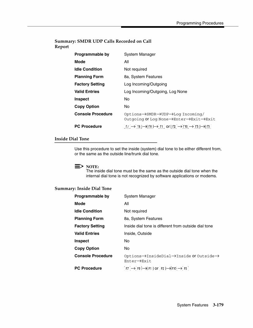
Programming Procedures
System Features 3-179
Summary: SMDR UDP Calls Recorded on Call Report 3
Programmable by System Manager
Mode All
Idle Condition Not required
Planning Form 8a, System Features
Factory Setting Log Incoming/Outgoing
Valid Entries Log Incoming/Outgoing, Log None
Inspect No
Copy Option No
Console Procedure Options→SMDR→UDP→Log Incoming/Outgoing or Log None→Enter→Exit→Exit
PC Procedure �→�→�→� or �→�→�→�
Inside Dial Tone 3
Use this procedure to set the inside (system) dial tone to be either different from, or the same as the outside line/trunk dial tone.
NOTE:The inside dial tone must be the same as the outside dial tone when the internal dial tone is not recognized by software applications or modems.
Summary: Inside Dial Tone 3
Programmable by System Manager
Mode All
Idle Condition Not required
Planning Form 8a, System Features
Factory Setting Inside dial tone is different from outside dial tone
Valid Entries Inside, Outside
Inspect No
Copy Option No
Console Procedure Options→InsideDial→Inside or Outside→ Enter→Exit
PC Procedure �→ →� or �→�→�
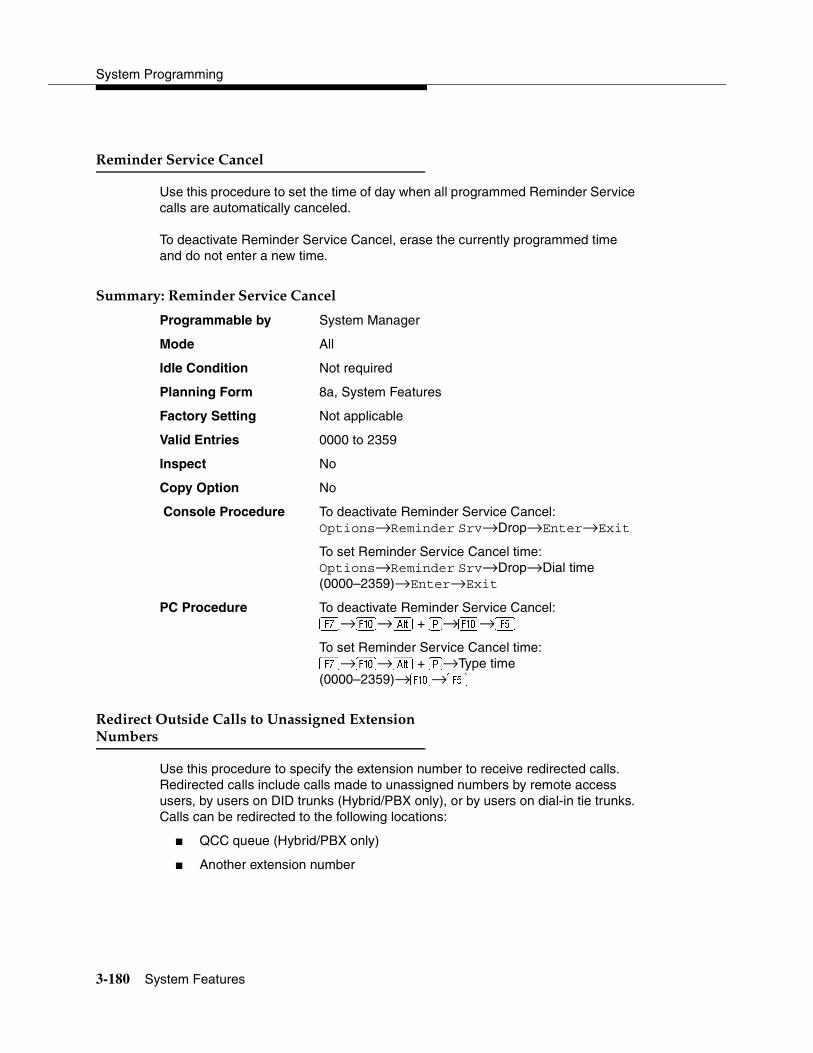
System Programming
3-180 System Features
Reminder Service Cancel 3
Use this procedure to set the time of day when all programmed Reminder Service calls are automatically canceled.
To deactivate Reminder Service Cancel, erase the currently programmed time and do not enter a new time.
Summary: Reminder Service Cancel 3
Programmable by System Manager
Mode All
Idle Condition Not required
Planning Form 8a, System Features
Factory Setting Not applicable
Valid Entries 0000 to 2359
Inspect No
Copy Option No
Console Procedure To deactivate Reminder Service Cancel:Options→Reminder Srv→Drop→Enter→Exit
To set Reminder Service Cancel time:Options→Reminder Srv→Drop→Dial time(0000–2359)→Enter→Exit
PC Procedure To deactivate Reminder Service Cancel:�→�→� + �→�→�
To set Reminder Service Cancel time:�→�→� + �→Type time (0000–2359)→�→�
Redirect Outside Calls to Unassigned Extension Numbers 3
Use this procedure to specify the extension number to receive redirected calls. Redirected calls include calls made to unassigned numbers by remote access users, by users on DID trunks (Hybrid/PBX only), or by users on dial-in tie trunks. Calls can be redirected to the following locations:
� QCC queue (Hybrid/PBX only)
� Another extension number

Programming Procedures
System Features 3-181
� A calling group
This setting does not affect calls received on DID trunks if you have specified that calls to unassigned DID extensions are to receive a fast busy signal. See ‘‘Invalid Destination’’ on page 3-66
Summary: Redirect Outside Calls to Unassigned Extension Numbers 3
Programmable by System Manager
Mode All
Idle Condition Not required
Planning Form 8a, System Features
Factory Setting Extension number of primary operator
Valid Entries QCC queue extension number, other extension number
Inspect No
Copy Option No
Console Procedure To select QCC queue:Options→More→Unassigned→QCC Queue→ Enter→Exit
To select extension or calling group:Options→More→Unassigned→Extension or Grp Calling→Enter→Dial ext. no. or group no.→ Enter→Exit
PC Procedure To select QCC queue:�→�→�→�→�→�
To select extension or calling group:�→�→�→� or �→Type ext. no. or group no.→�→�
Host System Dial Codes for Behind Switch Mode3
Use this procedure to assign the host system dial codes for the Transfer, Conference, and Drop features.
When multiline telephone users press the Transfer, Conference, or Drop button, a signal is sent to the host service and the communications system features are not accessed. Assigning dial codes to these features ensures that users can take advantage of them through the host system.

System Programming
3-182 System Features
NOTE:This procedure applies to Behind Switch mode only.
Summary: Host System Dial Codes for Behind Switch Mode 3
Programmable by System Manager
Mode Behind Switch
Idle Condition Not required
Planning Form 1, System Planning
Factory Setting No host dial codes are assigned
Valid Entries Host system dial code of up to six digits
Inspect No
Copy Option No
Console Procedure Options→More→BehndSwitch→Select feature→Drop→Dial host system dial code (up to 6 digits)→Enter→Exit→Exit
PC Procedure �→�→�→Select feature→� + �→ Type host system dial code (up to 6 digits)→ �→�→�
Recall Timer 3
Use this procedure to designate the length of the timed flash that is sent when Recall is used to disconnect a call and get a new dial tone without hanging up. Both the interval of the timed flash and the way Recall works depend on the type of telephone and system operating mode.
The recall timer should be reset if multiline telephone users experience either of the following problems:
� Nothing happens when the user presses the Recall button on an outside call. This indicates that the interval is too short and should be increased to 650 milliseconds or one second.
� In a system operating in Behind Switch mode, the call is disconnected when the user presses the Recall button on an outside call. This indicates that the interval is too long and should be decreased to 350 milliseconds.
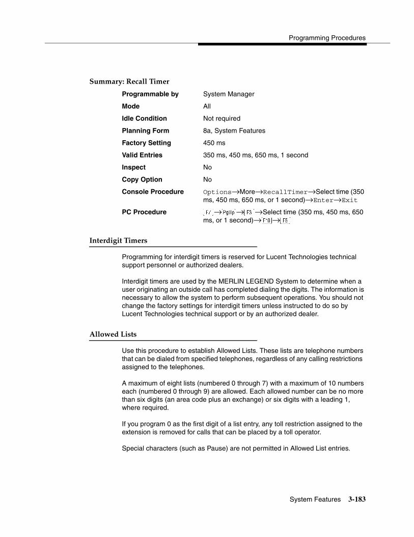
Programming Procedures
System Features 3-183
Summary: Recall Timer 3
Programmable by System Manager
Mode All
Idle Condition Not required
Planning Form 8a, System Features
Factory Setting 450 ms
Valid Entries 350 ms, 450 ms, 650 ms, 1 second
Inspect No
Copy Option No
Console Procedure Options→More→RecallTimer→Select time (350 ms, 450 ms, 650 ms, or 1 second)→Enter→Exit
PC Procedure �→�→�→Select time (350 ms, 450 ms, 650 ms, or 1 second)→�→�
Interdigit Timers 3
Programming for interdigit timers is reserved for Lucent Technologies technical support personnel or authorized dealers.
Interdigit timers are used by the MERLIN LEGEND System to determine when a user originating an outside call has completed dialing the digits. The information is necessary to allow the system to perform subsequent operations. You should not change the factory settings for interdigit timers unless instructed to do so by Lucent Technologies technical support or by an authorized dealer.
Allowed Lists 3
Use this procedure to establish Allowed Lists. These lists are telephone numbers that can be dialed from specified telephones, regardless of any calling restrictions assigned to the telephones.
A maximum of eight lists (numbered 0 through 7) with a maximum of 10 numbers each (numbered 0 through 9) are allowed. Each allowed number can be no more than six digits (an area code plus an exchange) or six digits with a leading 1, where required.
If you program 0 as the first digit of a list entry, any toll restriction assigned to the extension is removed for calls that can be placed by a toll operator.
Special characters (such as Pause) are not permitted in Allowed List entries.
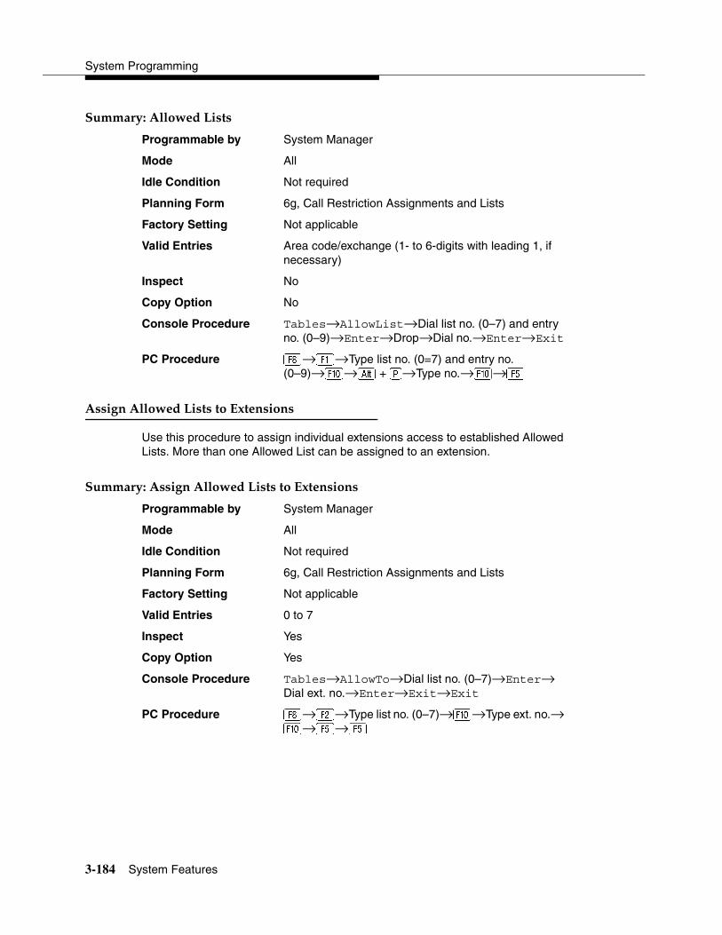
System Programming
3-184 System Features
Summary: Allowed Lists 3
Programmable by System Manager
Mode All
Idle Condition Not required
Planning Form 6g, Call Restriction Assignments and Lists
Factory Setting Not applicable
Valid Entries Area code/exchange (1- to 6-digits with leading 1, if necessary)
Inspect No
Copy Option No
Console Procedure Tables→AllowList→Dial list no. (0–7) and entry no. (0–9)→Enter→Drop→Dial no.→Enter→Exit
PC Procedure �→�→Type list no. (0=7) and entry no. (0–9)→�→� + �→Type no.→�→�
Assign Allowed Lists to Extensions 3
Use this procedure to assign individual extensions access to established Allowed Lists. More than one Allowed List can be assigned to an extension.
Summary: Assign Allowed Lists to Extensions 3
Programmable by System Manager
Mode All
Idle Condition Not required
Planning Form 6g, Call Restriction Assignments and Lists
Factory Setting Not applicable
Valid Entries 0 to 7
Inspect Yes
Copy Option Yes
Console Procedure Tables→AllowTo→Dial list no. (0–7)→Enter→Dial ext. no.→Enter→Exit→Exit
PC Procedure �→�→Type list no. (0–7)→�→Type ext. no.→ �→�→�
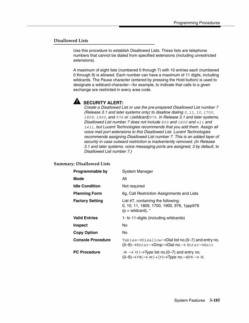
Programming Procedures
System Features 3-185
Disallowed Lists 3
Use this procedure to establish Disallowed Lists. These lists are telephone numbers that cannot be dialed from specified extensions (including unrestricted extensions).
A maximum of eight lists (numbered 0 through 7) with 10 entries each (numbered 0 through 9) is allowed. Each number can have a maximum of 11 digits, including wildcards. The Pause character (entered by pressing the Hold button) is used to designate a wildcard character—for example, to indicate that calls to a given exchange are restricted in every area code.
! SECURITY ALERT:Create a Disallowed List or use the pre-prepared Disallowed List number 7 (Release 3.1 and later systems only) to disallow dialing 0, 11, 10, 1700, 1809, 1900, and 976 or 1(wildcard)976. In Release 3.1 and later systems, Disallowed List number 7 does not include 800 and 1800 and 411 and 1411, but Lucent Technologies recommends that you add them. Assign all voice mail port extensions to this Disallowed List. Lucent Technologies recommends assigning Disallowed List number 7. This is an added layer of security in case outward restriction is inadvertently removed. (In Release 3.1 and later systems, voice messaging ports are assigned, 3 by default, to Disallowed List number 7.)
Summary: Disallowed Lists 3
Programmable by System Manager
Mode All
Idle Condition Not required
Planning Form 6g, Call Restriction Assignments and Lists
Factory Setting List #7, containing the following:0, 10, 11, 1809, 1700, 1900, 976, 1ppp976(p = wildcard), *
Valid Entries 1- to 11-digits (including wildcards)
Inspect No
Copy Option No
Console Procedure Tables→Disallow→Dial list no.(0–7) and entry no. (0–9)→Enter→Drop→Dial no.→ Enter→Exit
PC Procedure �→�→Type list no.(0–7) and entry no. (0–9)→�→� +�→Type no.→�→�

System Programming
3-186 Remote Access Features
Assign Disallowed Lists to Extensions 3
Use this procedure to assign established Disallowed Lists to individual extensions. Each restricted extension can be assigned to more than one list.
Summary: Assign Disallowed Lists to Extensions 3
Programmable by System Manager
Mode All
Idle Condition Not required
Planning Form 6g, Call Restriction Assignments and Lists
Factory Setting Not applicable
Valid Entries 0 to 7
Inspect Yes
Copy Option Yes
Console Procedure Tables→DisallowTo→Dial list no. (0–7)→ Enter→Dial ext. no.→Enter→Exit→Exit
PC Procedure �→→Type list no. (0–7)→�→Type ext. no.→ �→�→�
Remote Access Features 3
This section covers the following Remote Access features:
� Remote Access over Networked Tandem and Tie Trunks (Release 6.0 and later systems only)
� Remote Access Trunk Assignment
� Remote Access Automatic Callback
� Remote Access without Barrier Codes
� Remote Access Barrier Codes
� Remote Access with Barrier Codes
! SECURITY ALERT:As a customer of a new communications system, you should be aware that telephone fraud has become an increasingly prevalent problem. It can occur in many forms, despite the numerous efforts of telephone companies and telephone equipment manufacturers to control it. Some individuals use electronic devices to prevent or falsify records of these calls. Others charge calls to someone else’s number by illegally using lost or stolen calling cards,
Programming Procedures
Remote Access Features 3-187
billing innocent parties, clipping on to someone else’s line, or breaking into someone else’s telephone equipment physically or electronically. In certain instances, unauthorized individuals make connections to the public switched network through the use of remote access features.
The Remote Access feature of your system, if you choose to use it, permits off-premises callers to access the system from a remote telephone by using an 800 number or a 7- or 10-digit telephone number. The system returns an acknowledgment signaling the user to key in his or her barrier code, which is selected and programmed by the system manager. After the barrier code is accepted, the system returns dial tone to the user. If you do not program specific restrictions, the user will be able to place any call normally dialed from a telephone associated with the system. Such an off-premises network call is originated at and will be billed from the system location.
The Remote Access feature helps the customer, through proper administration, to minimize the ability of unauthorized persons to gain access to the network. Most commonly, telephone numbers and codes are compromised when overheard in a public location, through theft of a wallet or purse containing access information, or through carelessness (writing codes on a piece of paper and improperly discarding it). Additionally, hackers may use a computer to dial an access code and then publish the information to other hackers. Enormous charges can be run up quickly. It is the customer’s responsibility to take the appropriate steps to properly implement the features, evaluate and program the various restriction levels, and protect and distribute access codes only to individuals who have been fully advised of the sensitive nature of the access information.
Common carriers are required by law to collect their tariffed charges. While these charges are fraudulent charges when made by persons with criminal intent, applicable tariffs state that the customer of record is responsible for payment of all long-distance or other network charges. Lucent Technologies cannot be responsible for such charges and will not make any allowance or give any credit for charges that result from unauthorized access.
To minimize the risk of unauthorized access to your communications system, follow these basic rules:
� Use a nonpublished remote access number.
� Assign barrier codes randomly to users on a need-to-have basis, keeping a log of ALL authorized users and assigning one code to one person.
� Use random sequence barrier codes, which are less likely to be broken.
� Deactivate all unassigned codes promptly.

System Programming
3-188 Remote Access Features
� Ensure that remote access users are aware of their responsibility to keep the telephone number and any barrier codes secure.
� When possible, restrict the off-network capability of off-premises callers using the Calling Restrictions and Disallowed List capabilities.
� When possible, block out-of-hours calling.
� Frequently monitor system call detail reports for quicker detection of any unauthorized or abnormal calling patterns.
� Limit remote call forward to persons on a need-to-have basis.
� Always use the longest length password allowed on the system.
� Passwords should consist of a random, non-repetitive, hard-to-guess sequence of digits.
Remote Access over Networked Tandem PRIand Tie Trunks 3
In Release 6.0 and later systems, Hybrid/PBX mode only, an ARS call originating at a remote, private networked communications system can arrive on a networked tandem tie or PRI trunk of the local system and receive remote-access treatment automatically. This operation allows callers on one system to use lines on another system speedily and transparently when optimal cost efficiency dictates the need for lines connected to a different switch in the organization’s private network. (In prior systems and for calls over other remote access trunks, it is necessary to make an explicit remote-access call, enter a barrier code, and finally use ARS.)
To permit this operation, both the local and remote systems must be programmed using ARS and remote access options. If two or more different system managers program the private networked systems, they should work together to coordinate their efforts.
Local Users Calling out on Private Networked Lines 3
To implement this operation on a local system where callers will use the networked lines on a remote system, use the procedures outlined in the section, ‘‘Automatic Route Selection’’ on page 3-197.
Remote Users Calling out on Local Lines 3
When your system is in a private network with a remote system, you can set up your system so that remote users can use public switched network trunks connected to your control unit for cost-efficient calling. Your system treats such calls as remote access calls, but the networked user does not enter a barrier

Programming Procedures
Remote Access Features 3-189
code. Instead, the system applies default restrictions that apply to all tie and/or all non-tie trunks, as described later in this topic. These restrictions do not affect other remote-access trunks that are programmed for use with barrier codes.
Calling restrictions should be imposed at the remote originating switch using ARS and extension FRLs as necessary. In addition, it is unnecessary to assign tandem trunks for remote access. It is easiest if private networked systems that share outside facilities also use the same ARS access code (9, for example).
To implement this operation on a local system where callers on a remote networked system will use the local trunks connected to your MERLIN LEGEND Communications System control unit, use the procedures in this chapter as outlined below. The relevant topics provide additional details.
� It is not necessary to assign private networked trunks for remote access. Callback for non-local trunk-to-trunk tandem calls does not work. Automatic Callback can be used at the local system when all private networked trunks are busy.
� Specify that all tie trunks (that is, networked tandem tie trunks) and/or all non-tie trunks (that is, all PRI tandem trunks) will not require barrier codes. This will not affect calls dialing the remote access code if the trunks on the remote system are regular, assigned remote-access trunks accessed by remote access users on your own system. See ‘‘Remote Access without Barrier Codes’’ on page 3-191.
� Change the factory set class of restrictions, as necessary, on tie or non-tie trunks. Any necessary restrictions should be imposed by the system manager for a call at the originating switch. For example, extensions may be assigned a Disallowed List to prevent 900 and 976 calls. If certain private trunks are reserved for particular purposes, the remote system manager may use UDP routing FRLs for this purpose.
� Make any necessary changes to ARS in order to route remote users’ calls to yet another system if more cost effective, or to add or absorb digits (an area code, for example) before sending a call over a trunk that is connected to your system. See ‘‘Automatic Route Selection’’ on page 3-197 for the procedures.
Remote Access Trunk Assignment 3
Use this procedure to assign or remove the trunks used for remote access. You can also use this procedure to specify whether the Remote Access feature is dedicated (always used for remote access) or shared (used for remote access only when Night Service is activated).
Trunks used for dedicated remote access must not be assigned to ring into a calling group or the QCC queue (Hybrid/PBX mode only).
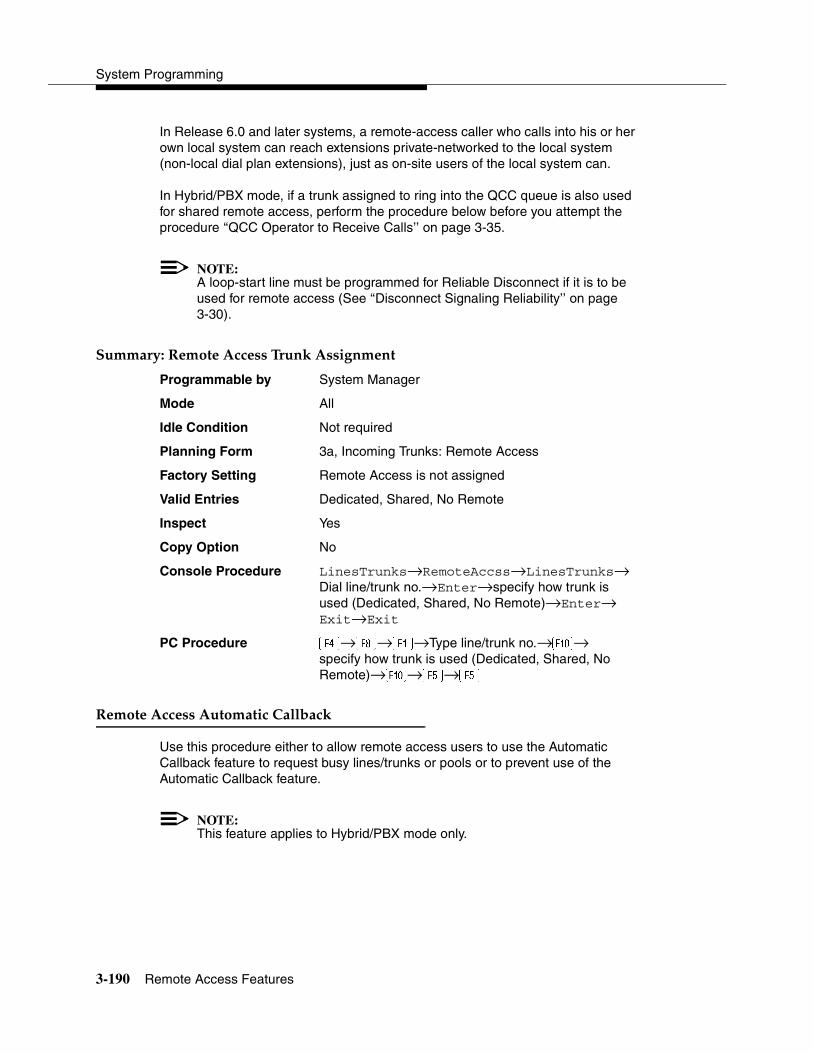
System Programming
3-190 Remote Access Features
In Release 6.0 and later systems, a remote-access caller who calls into his or her own local system can reach extensions private-networked to the local system (non-local dial plan extensions), just as on-site users of the local system can.
In Hybrid/PBX mode, if a trunk assigned to ring into the QCC queue is also used for shared remote access, perform the procedure below before you attempt the procedure ‘‘QCC Operator to Receive Calls’’ on page 3-35.
NOTE:A loop-start line must be programmed for Reliable Disconnect if it is to be used for remote access (See ‘‘Disconnect Signaling Reliability’’ on page 3-30).
Summary: Remote Access Trunk Assignment 3
Programmable by System Manager
Mode All
Idle Condition Not required
Planning Form 3a, Incoming Trunks: Remote Access
Factory Setting Remote Access is not assigned
Valid Entries Dedicated, Shared, No Remote
Inspect Yes
Copy Option No
Console Procedure LinesTrunks→RemoteAccss→LinesTrunks→Dial line/trunk no.→Enter→specify how trunk is used (Dedicated, Shared, No Remote)→Enter→ Exit→Exit
PC Procedure →�→�→Type line/trunk no.→�→specify how trunk is used (Dedicated, Shared, No Remote)→�→�→�
Remote Access Automatic Callback 3
Use this procedure either to allow remote access users to use the Automatic Callback feature to request busy lines/trunks or pools or to prevent use of the Automatic Callback feature.
NOTE:This feature applies to Hybrid/PBX mode only.
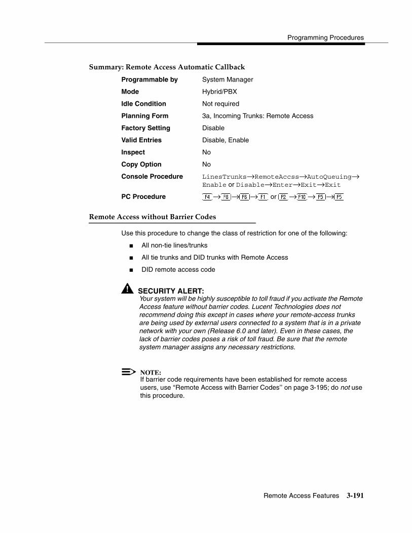
Programming Procedures
Remote Access Features 3-191
Summary: Remote Access Automatic Callback 3
Programmable by System Manager
Mode Hybrid/PBX
Idle Condition Not required
Planning Form 3a, Incoming Trunks: Remote Access
Factory Setting Disable
Valid Entries Disable, Enable
Inspect No
Copy Option No
Console Procedure LinesTrunks→RemoteAccss→AutoQueuing→Enable or Disable→Enter→Exit→Exit
PC Procedure →�→→� or �→�→�→�
Remote Access without Barrier Codes 3
Use this procedure to change the class of restriction for one of the following:
� All non-tie lines/trunks
� All tie trunks and DID trunks with Remote Access
� DID remote access code
! SECURITY ALERT:Your system will be highly susceptible to toll fraud if you activate the Remote Access feature without barrier codes. Lucent Technologies does not recommend doing this except in cases where your remote-access trunks are being used by external users connected to a system that is in a private network with your own (Release 6.0 and later). Even in these cases, the lack of barrier codes poses a risk of toll fraud. Be sure that the remote system manager assigns any necessary restrictions.
NOTE:If barrier code requirements have been established for remote access users, use ‘‘Remote Access with Barrier Codes’’ on page 3-195; do not use this procedure.
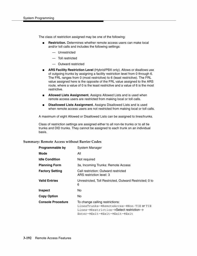
System Programming
3-192 Remote Access Features
The class of restriction assigned may be one of the following:
� Restriction. Determines whether remote access users can make local and/or toll calls and includes the following settings:
— Unrestricted
— Toll restricted
— Outward restricted
� ARS Facility Restriction Level (Hybrid/PBX only). Allows or disallows use of outgoing trunks by assigning a facility restriction level from 0 through 6. The FRL ranges from 0 (most restrictive) to 6 (least restrictive). The FRL value assigned here is the opposite of the FRL value assigned to the ARS route, where a value of 0 is the least restrictive and a value of 6 is the most restrictive.
� Allowed Lists Assignment. Assigns Allowed Lists and is used when remote access users are restricted from making local or toll calls.
� Disallowed Lists Assignment. Assigns Disallowed Lists and is used when remote access users are not restricted from making local or toll calls.
A maximum of eight Allowed or Disallowed Lists can be assigned to lines/trunks.
Class of restriction settings are assigned either to all non-tie trunks or to all tie trunks and DID trunks. They cannot be assigned to each trunk on an individual basis.
Summary: Remote Access without Barrier Codes 3
Programmable by System Manager
Mode All
Idle Condition Not required
Planning Form 3a, Incoming Trunks: Remote Access
Factory Setting Call restriction: Outward restrictedARS restriction level: 3
Valid Entries Unrestricted, Toll Restricted, Outward Restricted; 0 to 6
Inspect No
Copy Option No
Console Procedure To change calling restrictions:LinesTrunks→RemoteAccss→Non-TIE or TIE Lines→Restriction→Select restriction→ Enter→Exit→Exit→Exit→Exit

Programming Procedures
Remote Access Features 3-193
To change ARS Facility Restriction Level:LinesTrunks→RemoteAccss→Non-TIE or TIE Lines→ARS Restrict→Drop→Dial FRL value→Enter→Exit→Exit→Exit→Exit
To assign/remove Allowed Lists:LinesTrunks→RemoteAccss→Non-TIE or TIE Lines→Allow List→Dial list no.→Enter→ Exit→Exit→Exit→Exit
To assign/remove Disallowed Lists:LinesTrunks→RemoteAccss→Non-TIE or TIE Lines→DisallowLst→Dial list no.→ Enter→Exit→Exit→Exit→Exit
PC Procedure To change calling restrictions:→�→� or �→�→Select restriction→ �→�→�→�→�
To change ARS Facility Restriction Level:→�→� or �→�→� + �→Type FRL value→�→�→�→�→�
To assign/remove Allowed Lists:→�→� or �→→Type list no.→�→ �→�→�
To assign/remove Disallowed Lists:→�→� or �→→Type list no.→�→ �→�→�→�
Remote Access Barrier Codes 3
Use this procedure to establish or remove barrier code requirements, as well as to establish or remove the barrier codes themselves.
Barrier codes are security passwords that restrict users from making unauthorized remote access calls on tie and non-tie lines and trunks. Callers are allowed three attempts per call to enter the correct remote access barrier code. If the caller enters an incorrect barrier code or times out during code entry, the caller hears the retry tone. The caller can erase an entered code by dialing ** (two asterisks). Code erasure is counted as one of the three permitted attempts. After three unsuccessful attempts, the caller hears a reorder tone and the call is disconnected. If this happens, the SMDR contains sixteen 0s in the Account Code field to flag the three failed attempts.
A maximum of 16 barrier codes are allowed for all lines/trunks. Each of the 16 barrier codes may be programmed with its own class of restriction (COR).
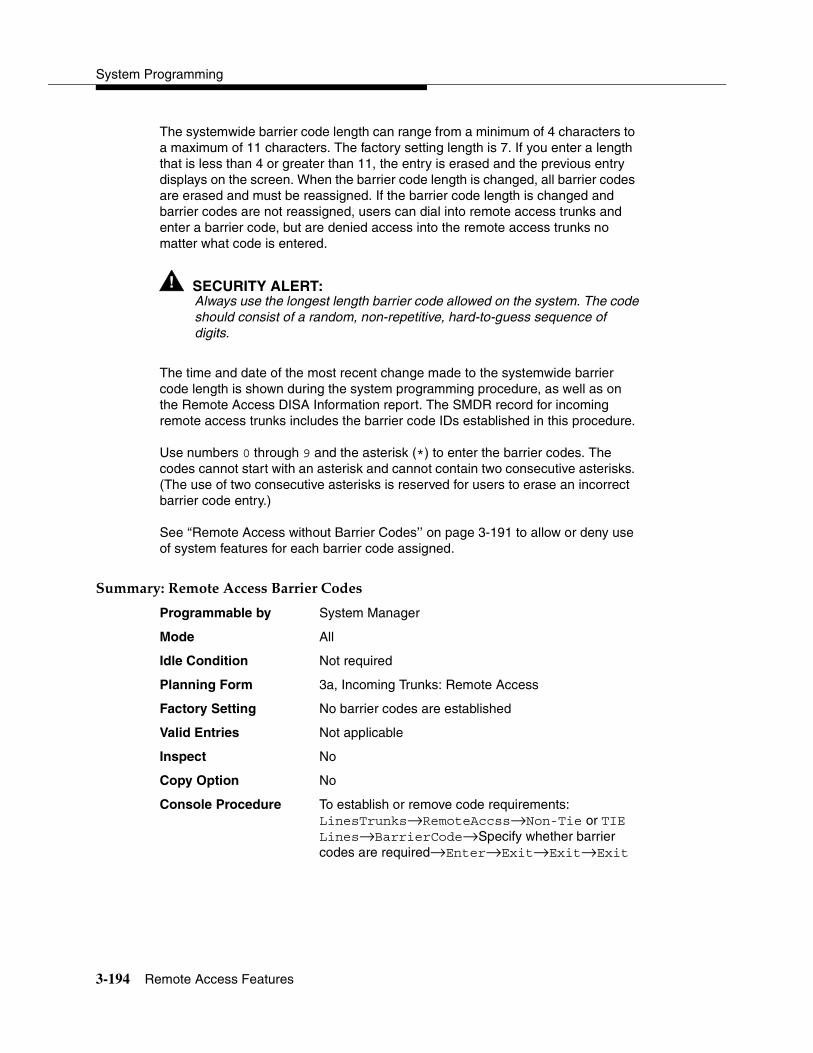
System Programming
3-194 Remote Access Features
The systemwide barrier code length can range from a minimum of 4 characters to a maximum of 11 characters. The factory setting length is 7. If you enter a length that is less than 4 or greater than 11, the entry is erased and the previous entry displays on the screen. When the barrier code length is changed, all barrier codes are erased and must be reassigned. If the barrier code length is changed and barrier codes are not reassigned, users can dial into remote access trunks and enter a barrier code, but are denied access into the remote access trunks no matter what code is entered.
! SECURITY ALERT:Always use the longest length barrier code allowed on the system. The codeshould consist of a random, non-repetitive, hard-to-guess sequence of digits.
The time and date of the most recent change made to the systemwide barrier code length is shown during the system programming procedure, as well as on the Remote Access DISA Information report. The SMDR record for incoming remote access trunks includes the barrier code IDs established in this procedure.
Use numbers 0 through 9 and the asterisk (*) to enter the barrier codes. The codes cannot start with an asterisk and cannot contain two consecutive asterisks. (The use of two consecutive asterisks is reserved for users to erase an incorrect barrier code entry.)
See ‘‘Remote Access without Barrier Codes’’ on page 3-191 to allow or deny use of system features for each barrier code assigned.
Summary: Remote Access Barrier Codes 3
Programmable by System Manager
Mode All
Idle Condition Not required
Planning Form 3a, Incoming Trunks: Remote Access
Factory Setting No barrier codes are established
Valid Entries Not applicable
Inspect No
Copy Option No
Console Procedure To establish or remove code requirements:LinesTrunks→RemoteAccss→Non-Tie or TIE Lines→BarrierCode→Specify whether barrier codes are required→Enter→Exit→Exit→Exit
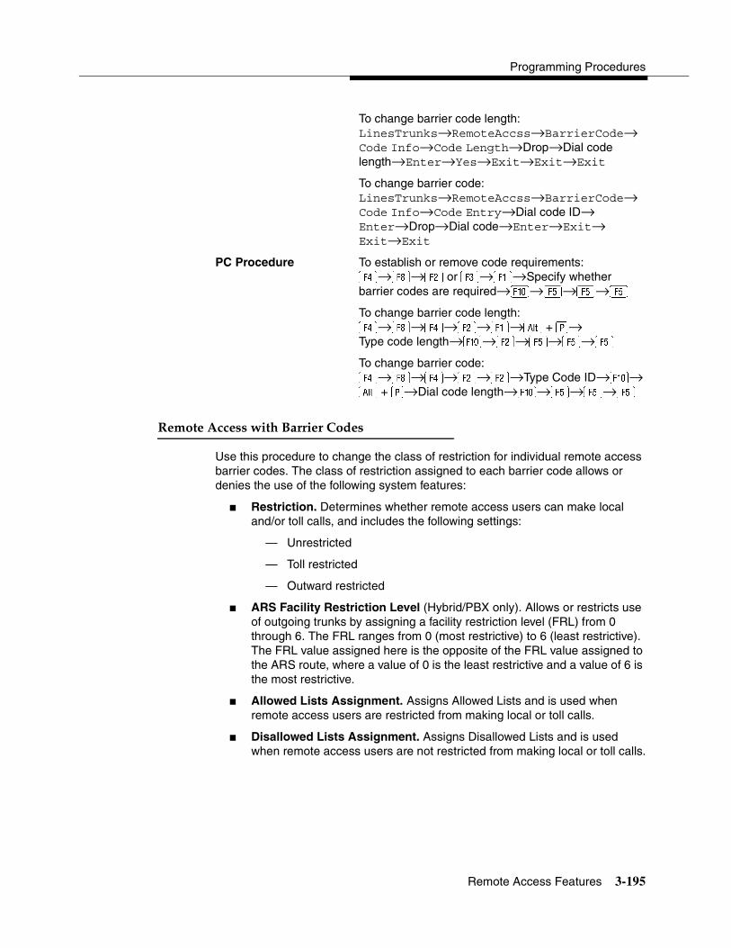
Programming Procedures
Remote Access Features 3-195
To change barrier code length:LinesTrunks→RemoteAccss→BarrierCode→Code Info→Code Length→Drop→Dial code length→Enter→Yes→Exit→Exit→Exit
To change barrier code:LinesTrunks→RemoteAccss→BarrierCode→Code Info→Code Entry→Dial code ID→ Enter→Drop→Dial code→Enter→Exit→ Exit→Exit
PC Procedure To establish or remove code requirements:→�→� or�→�→Specify whether barrier codes are required→�→�→�→�
To change barrier code length:→�→→�→�→� +�→Type code length→�→�→�→�→�
To change barrier code:→�→→�→�→Type Code ID→�→� + �→Dial code length→�→�→�→�
Remote Access with Barrier Codes 3
Use this procedure to change the class of restriction for individual remote access barrier codes. The class of restriction assigned to each barrier code allows or denies the use of the following system features:
� Restriction. Determines whether remote access users can make local and/or toll calls, and includes the following settings:
— Unrestricted
— Toll restricted
— Outward restricted
� ARS Facility Restriction Level (Hybrid/PBX only). Allows or restricts use of outgoing trunks by assigning a facility restriction level (FRL) from 0 through 6. The FRL ranges from 0 (most restrictive) to 6 (least restrictive). The FRL value assigned here is the opposite of the FRL value assigned to the ARS route, where a value of 0 is the least restrictive and a value of 6 is the most restrictive.
� Allowed Lists Assignment. Assigns Allowed Lists and is used when remote access users are restricted from making local or toll calls.
� Disallowed Lists Assignment. Assigns Disallowed Lists and is used when remote access users are not restricted from making local or toll calls.

System Programming
3-196 Remote Access Features
A maximum of eight Allowed or Disallowed Lists can be assigned to each barrier code. Class of restriction settings apply to individual barrier codes.
NOTE:If barrier code requirements have not been established or have been removed for remote access users, do not use this procedure. See ‘‘Remote Access without Barrier Codes’’ on page 3-191.
Summary: Remote Access with Barrier Codes 3
Programmable by System Manager
Mode All
Idle Condition Not required
Planning Form 3a, Incoming Trunks: Remote Access
Factory Setting Calling restrictions:Barrier Code: outward restrictedAll other barrier codes: unrestrictedARS restriction level: 3
Valid Entries Unrestricted, Toll Restricted, Outward Restricted; 0 to 6
Inspect No
Copy Option No
Console Procedure LinesTrunks→RemoteAccss→BarrierCode→Restriction→Dial barrier code no.→Enter→ Select restriction→Enter→ARS Restrict→Dial barrier code no.→Enter→Drop→Dial FRL value→Enter→Allow List or Disallow List→ Dial barrier code no. (1–16)→Enter→Dial list no.→ Enter→Exit→Exit→Exit→Exit
PC Procedure →�→→�→Type barrier code no.→ �→Select restriction→�→→Type barrier code no. (1–16)→�→� + �→Type FRL value→ �→ or�→Dial barrier code no.→ �→ �→�→�→�
Programming Procedures
Automatic Route Selection 3-197
Automatic Route Selection 3
This section contains programming procedures for the following Automatic Route Selection (ARS) features:
� 1 + 7-Digit Dialing Requirements
� ARS Tables
� Start and Stop Times for Subpatterns
� Pool Routing
� Facility Restriction Level (FRL)
� Digit Absorption
� Other Digits
� N11 Special Numbers Tables
� Dial 0 Table
� Voice and/or Data Routing
NOTE:ARS applies to Hybrid/PBX mode only.
ARS over Private Networked Tandem PRI and Tie Trunks 3
In Release 6.0 and later systems, Hybrid/PBX mode only, callers on one system can use lines on another system quickly and transparently for optimal cost by routing calls to a different switch in the organization’s private network (in prior systems, it is necessary to make an explicit remote-access call, enter a barrier code, and finally use ARS). To permit this operation, both the local and remote systems must be programmed using ARS and remote access options.
Remote Users Calling out on Local Private Networked Lines 3
To implement this operation on a local system where remote callers will use the private networked lines connected to your system, use the procedures outlined in the section ‘‘Remote Access Features’’ on page 3-186.
Local Users Calling out on Private Networked Lines 3
To implement this operation on a local system where callers will use the trunks on a remote system, use the procedures outlined in this section. The relevant topics provide additional details.

System Programming
3-198 Automatic Route Selection
� Assign the private networked tandem tie and/or PRI tandem trunks to a pool or pools including only those types of trunks. See ‘‘Trunks to Pools Assignment’’ on page 3-38.
� Use one or more ARS tables for routing calls. Typically, you might need an area code table. For example, if the remote system is in the 617 area code, and your local system is in the 908 area code, the area code table that you set up should include the entry 617. The type of table required depends upon how users in your system will employ private networked lines. At the remote system, ARS can be used, if necessary, to route the call to yet another networked system. See ‘‘ARS Tables’’ on page 3-199.
� Set up the subpatterns for the table. In doing so, you may wish to check with the remote system manager to ensure that routing will stipulate the most cost-effective timing based on the rates at the remote location. If the remote system is in a different time zone from your own, you may need to take this into consideration as well. See ‘‘Start and Stop Times for Subpatterns’’ on page 3-200.
� Assign each tandem and/or tie trunk pool to an ARS table. See ‘‘Pool Routing’’ on page 3-201.
� Assign appropriate Facility Restriction Levels to the routes and to the extensions that will use the private network lines. Factory settings restrict toll calls. See ‘‘Facility Restriction Level’’ on page 3-203 and ‘‘ARS Restriction Level for Extensions’’ on page 3-123, respectively.
� Assign absorbed and other (added) digits as required by the final destination. The local ARS feature adds (prepends) the ARS access code of the remote system. At the remote system, digit absorption may be needed. For example, if local callers are in the 908 area code but the private network lines are connected to a system in the 617 area code, callers might dial 916175551212, where 9 is the local ARS access code. At the remote system, because the call would be a local call, the absorbed digits would be 1617. See the ARS topics ‘‘Digit Absorption’’ on page 3-204 and ‘‘Other Digits’’ on page 3-205 for additional information.
! SECURITY ALERT:In Release 6.0 and later systems, do not place remote ARS access codes in the non-local dial plan by specifying, for example, a non-local extension range such as 9000–9050 when the remote ARS access code is 9. Doing so allows DID callers to make outside calls through the remote switch and may allow transferring of outside callers to outside dial tone on a remote switch, possibly resulting in toll fraud.

Programming Procedures
Automatic Route Selection 3-199
1 + 7-Digit Dialing Requirements 3
Use this procedure for calls placed within the same (home) area code as the system. The procedure allows you to specify whether or not the local telephone company requires a 1 to precede the 7-digit number. The two available settings are:
� Within Area Code. Requires that a 1 plus a 7-digit number must be dialed; the system checks the 1 plus 7-digit tables for routing.
� Not within Area Code. Does not require that a 1 precede the 7-digit number (the system does this automatically).
Summary: 1 + 7-Digit Dialing Requirements 3
Programmable by System Manager
Mode Hybrid/PBX
Idle Condition Not required
Planning Form 3f, Automatic Route Selection Tables
Factory Setting Not within area code
Valid Entries Not within area code, Within area code
Inspect No
Copy Option No
Console Procedure Tables→ARS→ARS 1+7Dial→Within Area Code or Not within Area Code→Enter→ Exit→Exit
PC Procedure �→→�→� or�→�→�→�
ARS Tables 3
Use this procedure for the following tasks:
� To specify type of table (6-digit, area code, exchange,or 1 plus 7-digit number)
� To add or change area codes to be included in each table
� To add or change exchanges to be included in each table
A maximum of 16 tables can be established, numbered 1 through 16. Each table can have a maximum of 100 entries, numbered 1 through 100. Tables 17 and 18, the Default Toll and Default Local tables respectively, cannot be changed.
The first entry in a 6-digit table must be the area code. Subsequent entries consist of exchanges within that area code.
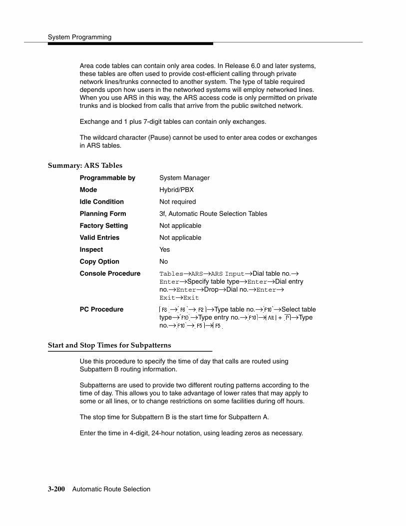
System Programming
3-200 Automatic Route Selection
Area code tables can contain only area codes. In Release 6.0 and later systems, these tables are often used to provide cost-efficient calling through private network lines/trunks connected to another system. The type of table required depends upon how users in the networked systems will employ networked lines. When you use ARS in this way, the ARS access code is only permitted on private trunks and is blocked from calls that arrive from the public switched network.
Exchange and 1 plus 7-digit tables can contain only exchanges.
The wildcard character (Pause) cannot be used to enter area codes or exchanges in ARS tables.
Summary: ARS Tables 3
Programmable by System Manager
Mode Hybrid/PBX
Idle Condition Not required
Planning Form 3f, Automatic Route Selection Tables
Factory Setting Not applicable
Valid Entries Not applicable
Inspect Yes
Copy Option No
Console Procedure Tables→ARS→ARS Input→Dial table no.→ Enter→Specify table type→Enter→Dial entry no.→Enter→Drop→Dial no.→Enter→ Exit→Exit
PC Procedure �→→�→Type table no.→�→Select table type→�→Type entry no.→�→� + �→Type no.→�→�→�
Start and Stop Times for Subpatterns 3
Use this procedure to specify the time of day that calls are routed using Subpattern B routing information.
Subpatterns are used to provide two different routing patterns according to the time of day. This allows you to take advantage of lower rates that may apply to some or all lines, or to change restrictions on some facilities during off hours.
The stop time for Subpattern B is the start time for Subpattern A.
Enter the time in 4-digit, 24-hour notation, using leading zeros as necessary.

Programming Procedures
Automatic Route Selection 3-201
In Release 6.0 and later systems, if you are setting up ARS to allow local users to make cost-efficient calls on trunks connected to remote systems, you may wish to check with the remote system manager to ensure that routing stipulates the most cost-effective timing based on the rates at the remote location. If the remote system is in a different time zone from your own, you may need to take this into consideration as well
Summary: Start and Stop Times for Subpatterns 3
Programmable by System Manager
Mode Hybrid/PBX
Idle Condition Not required
Planning Form 3f, Automatic Route Selection Tables3g, Automatic Route Selection Default andSpecial Numbers Tables
Factory Setting No time is specified, thus all calls are routed according to Subpattern A.
Valid Entries 0000 to 2359
Inspect No
Copy Option No
Console Procedure Tables→ARS→Sub B Start→Dial table no.→ Enter→Drop→Dial start time (0000–2359)→ Enter→Sub B Stop→Dial table no.→ Enter→Drop→Dial stop time→Enter→ Exit→Exit
PC Procedure �→→�→Type table no.→�→� + �→Type start time (0000–2359)→�→ �→Type table no.→�→� + �→Type stop time→�→�→�
Pool Routing 3
Use this procedure to identify the trunk pools on which to route calls to area codes and/or exchanges included in ARS tables.
A maximum of six routes (numbered 1 through 6) can be specified for each subpattern. Pool routing is programmed for Tables 1 through 16. Tables 17 and 18, the Default Toll and Default Local tables respectively, are factory set to the main pool and can be changed.

System Programming
3-202 Automatic Route Selection
NOTES:� In Release 6.0 and later, when routing for ARS 10*** and 101****
equal-access calls (Interexchange Carrier or IXC) from a private networked switch that is not connected to the public switched network and only has private network tandem trunks, the private network tandem trunks must be assigned to the main pool on the system where ARS is dialed. The ARS access code for the caller’s system must match that of the system where the public switched network trunks are connected. For this reason, consider using the same ARS access code for all systems in the private network.
� For Dial 0 and Special Numbers N11 calls (for example, 411 or 911) routed from systems with only private trunks, the private trunks must be assigned to the main pool, and the ARS access code of the remote system must be prepended to the dialed number (see ‘‘Dial 0 Table’’ on page 3-207 and ‘‘N11 Special Numbers Tables’’ on page 3-206). ARS access codes, therefore, should be the same.
Summary: Pool Routing 3
Programmable by System Manager
Mode Hybrid/PBX
Idle Condition Not required
Planning Form 3f, Automatic Route Selection Tables3g, Automatic Route Selection Default and Special Numbers Tables
Factory Setting Not applicable
Valid Entries Not applicable
Inspect No
Copy Option No
Console Procedure Tables→ARS→Sub A Pools or Sub B Pool→Dial table no. and pool route no.→Enter→Dial pool dial-out code→Enter→Exit→Exit
PC Procedure �→→� or �→Type table no. and pool route no.→�→Type pool dial-out code→ �→�→�

Programming Procedures
Automatic Route Selection 3-203
Facility Restriction Level 3
Use this procedure to assign a Facility Restriction Level (FRL) to each route. The FRL ranges from 0 (least restrictive) to 6 (most restrictive) and is used to restrict user access to the route. The FRL assigned to extensions and remote access users is the opposite of the FRL assigned to routes, where 0 is the most restrictive and 6 is the least restrictive.
NOTE:Pool routes must be programmed before you assign Facility Restriction Levels.
Facility Restriction Levels are assigned to Tables 1 through 18. Tables 17 and 18, the Default Toll and Default Local tables respectively, cannot be changed.
Summary: Facility Restriction Level 3
Programmable by System Manager
Mode Hybrid/PBX
Idle Condition Not required
Planning Form 3f, Automatic Route Selection Tables3g, Automatic Route Selection Default and Special Numbers Tables
Factory Setting 3 (beginning with Release 3.1, Table 18, the Default Local table has a factory setting of 2)
Valid Entries 0 to 6
Inspect No
Copy Option No
Console Procedure Tables→ARS→Sub A FRL or More and Sub B FRL→Dial table no. (1–18) and pool route no. (1–6)→ Enter→Dial restriction level (0–6)→Enter→ Exit→Exit
PC Procedure �→→ or� and �→Type table no. (1–18) and pool route no. (1–6)→�→Type restriction level (0–6)→�→�→�
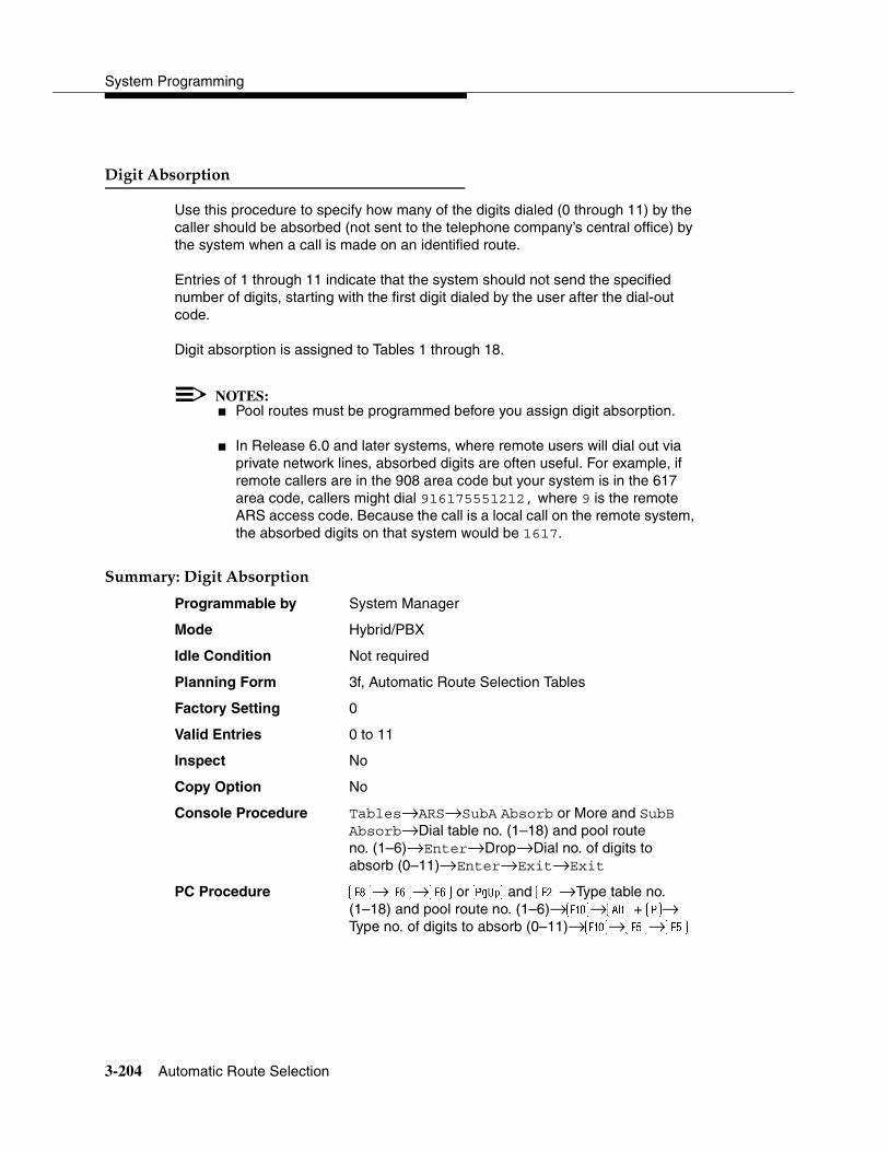
System Programming
3-204 Automatic Route Selection
Digit Absorption 3
Use this procedure to specify how many of the digits dialed (0 through 11) by the caller should be absorbed (not sent to the telephone company’s central office) by the system when a call is made on an identified route.
Entries of 1 through 11 indicate that the system should not send the specified number of digits, starting with the first digit dialed by the user after the dial-out code.
Digit absorption is assigned to Tables 1 through 18.
NOTES:� Pool routes must be programmed before you assign digit absorption.
� In Release 6.0 and later systems, where remote users will dial out via private network lines, absorbed digits are often useful. For example, if remote callers are in the 908 area code but your system is in the 617 area code, callers might dial 916175551212, where 9 is the remote ARS access code. Because the call is a local call on the remote system, the absorbed digits on that system would be 1617.
Summary: Digit Absorption 3
Programmable by System Manager
Mode Hybrid/PBX
Idle Condition Not required
Planning Form 3f, Automatic Route Selection Tables
Factory Setting 0
Valid Entries 0 to 11
Inspect No
Copy Option No
Console Procedure Tables→ARS→SubA Absorb or More and SubB Absorb→Dial table no. (1–18) and pool route no. (1–6)→Enter→Drop→Dial no. of digits to absorb (0–11)→Enter→Exit→Exit
PC Procedure �→→ or � and �→Type table no. (1–18) and pool route no. (1–6)→�→� + �→ Type no. of digits to absorb (0–11)→�→�→�
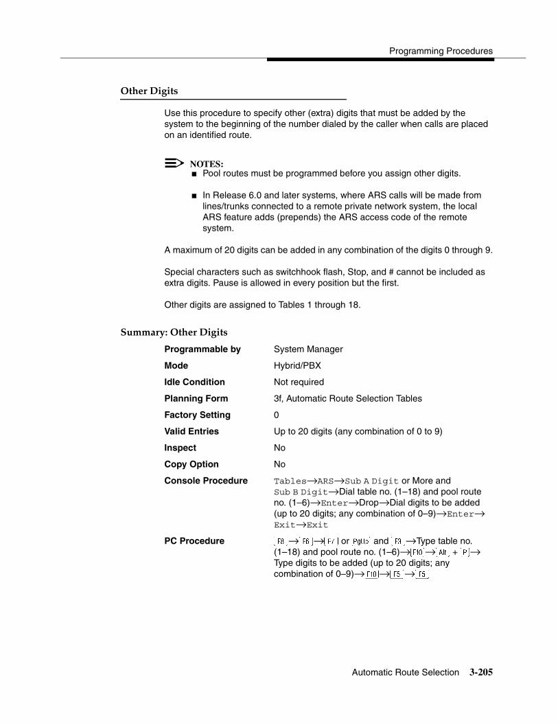
Programming Procedures
Automatic Route Selection 3-205
Other Digits 3
Use this procedure to specify other (extra) digits that must be added by the system to the beginning of the number dialed by the caller when calls are placed on an identified route.
NOTES:� Pool routes must be programmed before you assign other digits.
� In Release 6.0 and later systems, where ARS calls will be made from lines/trunks connected to a remote private network system, the local ARS feature adds (prepends) the ARS access code of the remote system.
A maximum of 20 digits can be added in any combination of the digits 0 through 9.
Special characters such as switchhook flash, Stop, and # cannot be included as extra digits. Pause is allowed in every position but the first.
Other digits are assigned to Tables 1 through 18.
Summary: Other Digits 3
Programmable by System Manager
Mode Hybrid/PBX
Idle Condition Not required
Planning Form 3f, Automatic Route Selection Tables
Factory Setting 0
Valid Entries Up to 20 digits (any combination of 0 to 9)
Inspect No
Copy Option No
Console Procedure Tables→ARS→Sub A Digit or More and Sub B Digit→Dial table no. (1–18) and pool route no. (1–6)→Enter→Drop→Dial digits to be added (up to 20 digits; any combination of 0–9)→Enter→ Exit→Exit
PC Procedure �→→� or � and �→Type table no.(1–18) and pool route no. (1–6)→�→� + �→ Type digits to be added (up to 20 digits; any combination of 0–9)→�→�→�
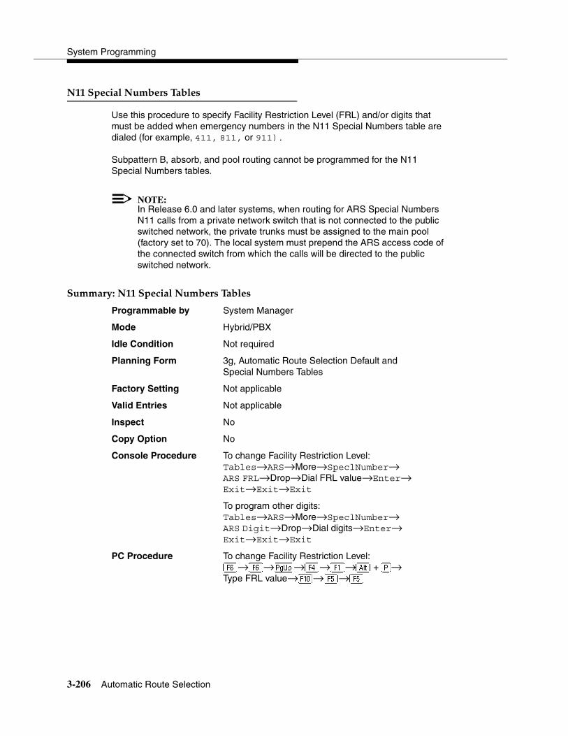
System Programming
3-206 Automatic Route Selection
N11 Special Numbers Tables 3
Use this procedure to specify Facility Restriction Level (FRL) and/or digits that must be added when emergency numbers in the N11 Special Numbers table are dialed (for example, 411, 811, or 911).
Subpattern B, absorb, and pool routing cannot be programmed for the N11 Special Numbers tables.
NOTE:In Release 6.0 and later systems, when routing for ARS Special Numbers N11 calls from a private network switch that is not connected to the public switched network, the private trunks must be assigned to the main pool (factory set to 70). The local system must prepend the ARS access code of the connected switch from which the calls will be directed to the public switched network.
Summary: N11 Special Numbers Tables 3
Programmable by System Manager
Mode Hybrid/PBX
Idle Condition Not required
Planning Form 3g, Automatic Route Selection Default and Special Numbers Tables
Factory Setting Not applicable
Valid Entries Not applicable
Inspect No
Copy Option No
Console Procedure To change Facility Restriction Level:Tables→ARS→More→SpeclNumber→ARS FRL→Drop→Dial FRL value→Enter→ Exit→Exit→Exit
To program other digits:Tables→ARS→More→SpeclNumber→ARS Digit→Drop→Dial digits→Enter→ Exit→Exit→Exit
PC Procedure To change Facility Restriction Level:�→→�→→�→� + �→Type FRL value→�→�→�

Programming Procedures
Automatic Route Selection 3-207
To program other digits:�→→�→→�→� + �→Type digits→�→�→�
Dial 0 Table 3
Use this procedure to specify pool routing, Facility Restriction Level (FRL), and Other Digits for the Dial 0 table.
Only one route can be specified. The Subpattern B route cannot be specified for this table, and digit absorption cannot be specified.
NOTE:In Release 6.0 and later systems, when routing for ARS Dial 0 calls via a private network switch that is not connected to the public switched network, the external private trunks must be assigned to a pool, and the ARS access code must be prepended to the dialed number using this procedure.
Summary: Dial 0 Table 3
Programmable by System Manager
Mode Hybrid/PBX
Idle Condition Not required
Planning Form 3g, Automatic Route Selection Default and Special Numbers Tables
Factory Setting 3
Valid Entries 0 to 6
Inspect No
Copy Option No
Console Procedure Tables→ARS→More→Dial 0→ARS Pool or ARS FRL (0–6) or ARS Digits→Dial value→Enter→Exit→Exit→Exit
PC Procedure �→→�→→� or � (0–6) or �→Type value→�→�→�→�
System Programming
3-208 Uniform Dial Plan Routing
Voice and/or Data Routing 3
Use this procedure to route voice, data, or voice and data. The voice/data specification is used mainly in conjunction with PRI. See ‘‘PRI Facilities’’ on page 3-67, especially its subtopic, ‘‘Outgoing Tables’’ on page 3-83.
Voice/data routes can be associated with Subpattern A or Subpattern B.
Summary: Voice and/or Data Routing 3
Programmable by System Manager
Mode Hybrid/PBX
Idle Condition Not required
Planning Form 3g, Automatic Route Selection Default and Special Numbers Tables
Factory Setting Voice
Valid Entries Voice Only, Data Only, Voice/Data
Inspect No
Copy Option No
Console Procedure Tables→ARS→More→Sub A Data or Sub B Data→Dial table no. and route no.→Enter→Select capability (Voice Only, Data Only, or Voice/Data)→Enter→Exit→Exit
PC Procedure �→→�→� or �→Type table no. and route no.→�→Select capability (Voice Only, Data Only, or Voice/Data)→�→�→�
Uniform Dial Plan Routing 3
This section includes programming procedures for assigning Uniform Dial Plan (UDP) Routing, available for Hybrid/PBX mode in Release 6.0 and later systems only.
UDP Routing is very similar to Automatic Route Selection (ARS). UDP Routing allows system users to reach non-local extensions at a remote DEFINITY or MERLIN LEGEND Communications System that is connected to the local system in a private network. Users simply dial the non-local extension number as they would an inside extension number. Then UDP Routing associates the dialed extension number with one of up to 20 programmed patterns. For each pattern, you can specify up to four routes. For each route, you specify a pool dial-out code.
Programming Procedures
Uniform Dial Plan Routing 3-209
Then you can program Facility Restriction Levels (FRLs), absorbed digits, added digits, and voice and/or data capability.
NOTE:Before assigning routes, patterns must be assigned to non-local extensions, which is part of the numbering of the extensions. To perform this procedure, see ‘‘Non-Local Dial Plan Extension Ranges’’ on page 3-16.
This section contains programming procedures for the following UDP Routing features:
� UDP Pool Routing
� Facility Restriction Level (FRL)
� Digit Absorption
� Other Digits
� Voice and/or Data Routing
! SECURITY ALERT:Do not include the ARS codes of non-local systems in the non-local dial plan, or calling restrictions may be violated.
Refer to the Network Reference for additional information.
UDP Pool Routing 3
Before beginning this procedure, assign tandem tie or PRI trunks to pools. To do so, see ‘‘Trunks to Pools Assignment’’ on page 3-38. In UDP routing, routes (1–4) are associated with patterns, which are assigned first. Each route has various attributes (FRL, digit absorption, and so on) for call delivery. You may assign from one to four routes, with Route 1 having the highest priority. See the Network Reference for additional information.
In many cases, only one pool may be needed. Multiple pools, however, can help prioritize certain types of calls and maximize the use of shared facilities.
PRI tandem trunk pools, if available, should be included in the first route.
! SECURITY ALERT:In Release 6.0 and later systems (Hybrid/PBX mode only), do not provide dial access to PRI or tie tandem trunk pools or assign these trunk pools to buttons on telephones or DSS buttons. Use ARS to provide access to a remote private network system’s trunks for making outside calls. System

System Programming
3-210 Uniform Dial Plan Routing
users can reach extensions on the remote system by using normal calling procedures.
Summary: UDP Pool Routing 3
Programmable by System Manager
Mode Hybrid/PBX
Idle Condition Not required
Planning Form Non-Local Dial Plan Administration Form in the Installation Specification
Factory Setting Not applicable
Valid Entries Routes (1–4)
Inspect Yes
Copy Option No
Console Procedure Tables→UDP Routing→Dial pattern no. (1–20)→ Enter→Dial route no. (1–4)→Enter→Pool→Dial pool dial-out code (up to 4 digits)→Enter→ Exit→Exit→Exit→Exit
PC Procedure �→�→Type pattern no. (1–20)→�→Type route no. (1–4)→�→�→Type pool dial-out code (up to 4 digits)→�→�→�→�→�
UDP Facility Restriction Level 3
Use this procedure to assign a Facility Restriction Level (FRL) to each UDP route. The FRL ranges from 0 (least restrictive) to 6 (most restrictive) and prevents users from accessing the route. The FRL assigned to extensions and remote access users is the opposite of the FRL assigned to routes, with 0 being the most restrictive FRL, and 6 the least restrictive. A call will succeed if the extension’s (or remote access) FRL is greater than or equal to the facility’s FRL.
FRLs assigned to extensions (or remote access) apply not only to ARS calls but also to calls for non-local dial plan extensions connected by private trunks to your local system. For this reason, use care in assigning FRLs both to extensions and to UDP routes. For example, if a user must be restricted from toll calls on your local system, you may need to plan UDP routes’ FRLs to be unrestricted so that the user can reach necessary non-local dial plan extensions. For information about assigning FRLs to extensions, see ‘‘ARS Restriction Level for Extensions’’ on page 3-123.
Programming Procedures
Uniform Dial Plan Routing 3-211
NOTES:� UDP pool routes must be programmed before you assign Facility
Restriction Levels to those routes.
� Extension outward and toll calling restrictions are removed when a user dials a non-local dial plan extension. FRL extension restrictions, however, remain in effect but are not sent with the call.
� If you have Centralized Voice Messaging, program an FRL of 0 for the routes used to send calls to Centralized Voice Messaging. See the Network Reference for additional information.
Summary: UDP Route Facility Restriction Level 3
Programmable by System Manager
Mode Hybrid/PBX
Idle Condition Not required
Planning Form Non-Local Dial Plan Administration Form in the Installation Specification
Factory Setting 3
Valid Entries 0 to 6
Inspect No
Copy Option No
Console Procedure Tables→UDP Routing→Dial pattern no. (1–20)→ Enter→Dial route no. (1–4)→Enter→FRL→Dial restriction level (0–6)→Enter→Exit→Exit→ Exit→Exit
PC Procedure �→�→Enter pattern no. (1–20)→�→Type route no. (1–4)→�→�→Type restriction level (0–6)→�→�→�→�→�
UDP Digit Absorption 3
Use this procedure to specify how many of the digits dialed (0 to 11) by the caller should be absorbed (not sent over the trunk) by the system when a UDP call to a non-local extension is made on an identified route. If the number is dialed without a pool access code or without using a Pool button, therefore, the dialed digits correspond to the non-local dial plan numbering. Digit absorption can be used to modify the digits that are actually sent to the remote system.
Entries of 1 through 11 indicate that the system should not send the specified number of digits, starting with the first digit dialed by the user.
System Programming
3-212 Uniform Dial Plan Routing
NOTES:� UDP pool routes must be programmed before you assign digit
absorption.
� Do not use this procedure to overcome conflicts between local and remote extension numbering. Such conflicts can result in numerous problems with system features.
Summary: UDP Digit Absorption 3
Programmable by System Manager
Mode Hybrid/PBX
Idle Condition Not required
Planning Form Non-Local Dial Plan Administration Form in the Installation Specification
Factory Setting 0
Valid Entries 0 to 11
Inspect No
Copy Option No
Console Procedure Tables→UDP Routing→Dial pattern no. (1–20)→ Enter→Dial route no. (1–4)→Enter→Absorb→ Drop→Dial number of absorption digits (0–11)→ Enter→Exit→Exit→Exit→Exit
PC Procedure �→�→Enter pattern no. (1–20)→�→Type route no. (1–4)→�→�→� + �→Type number of digits to absorb (0–11)→�→ �→�→�→�
UDP Other Digits 3
Use this procedure to specify other (extra) digits that must be added by the system to the beginning of the dialed digits when calls are placed on an identified route. You may need to prepend a digit in order to accommodate the 5-digit numbering of DEFINITY Communications System extensions in your private network. For more information about techniques for handling these non-local dial plan extension numbers, see ‘‘Non-Local Dial Plan Extension Ranges’’ on page 3-16.
The user does not use a Pool button or pool dial-out code. The dialed digits, therefore, correspond to the non-local dial plan numbering.

Programming Procedures
Uniform Dial Plan Routing 3-213
NOTES:� UDP pool routes must be programmed before you assign digit
absorption.
� Do not use this procedure to overcome conflicts between local and remote extension numbering. Such conflicts can result in numerous problems with system features.
A maximum of 20 digits can be added, in any combination of digits 0 through 9.
Special characters such as switchhook flash, Stop, and # cannot be included as extra digits. Pause is allowed in every position except the first.
Summary: UDP Other Digits 3
Programmable by System Manager
Mode Hybrid/PBX
Idle Condition Not required
Planning Form Non-Local Dial Plan Administration Form in the Installation Specification
Factory Setting 0
Valid Entries Up to 20 digits (any combination of 0 to 9)
Inspect No
Copy Option No
Console Procedure Tables→UDP Routing→Dial pattern no. (1–20)→ Enter→Dial route no. (1–4)→Enter→Digits→Drop→Dial digits to add (up to 20; any combination of 0–9)→Enter→Exit→Exit→Exit→Exit
PC Procedure �→�→Enter pattern no. (1–20)→�→Type route no. (1–4)→�→→� + �→Type digits to add (up to 20; any combination of0–9)→�→�→�→�→�
UDP Voice and/or Data Routing 3
Use this procedure to route voice, data, or voice and data. For UDP routing, the voice/data specification is used in conjunction with PRI tandem trunks. See ‘‘PRI Facilities’’ on page 3-67 for more information. When using Fractional-T1 tandem trunks, each channel on the trunk can be used for either voice or data, but not for voice/data. See ‘‘DS1 Facilities’’ on page 3-45 for more information.
Voice/data routes can be associated with any UDP pattern.

System Programming
3-214 Night Service
Summary: UDP Voice and/or Data Routing 3
Programmable by System Manager
Mode Hybrid/PBX
Idle Condition Not required
Planning Form Non-Local Dial Plan Administration Form in the Installation Specification
Factory Setting Voice/Data
Valid Entries Voice Only, Data Only, Voice/Data
Inspect No
Copy Option No
Console Procedure Tables→UDP Routing→Dial pattern no.→ Enter→Dial route no.→Enter→Data→Select capability (Voice Only, Data Only, Voice/Data)→ Enter→Exit→Exit→Exit→Exit
PC Procedure �→�→Type pattern no.→�→Type route no.→ �→→Select capability (Voice Only, Data Only, Voice Data)→�→�→�→�→�
Night Service 3
The procedures in this section cover how to program the following optional Night Service features:
� Night Service Group Assignment
� Night Service with Outward Restriction
� Night Service with Time Set
� Night Service with Coverage Control
Night Service Group Assignment 3
Use this procedure to assign extensions and calling groups to a Night Service group for coverage after hours.
A maximum of eight Night Service groups can be assigned (no more than one for each operator position assigned). Any number of extensions can be assigned to a Night Service group, and an extension can belong to more than one group.
A calling group can also be assigned to a Night Service group. This applies only to Release 2.0 or later.

Programming Procedures
Night Service 3-215
Beginning with Release 4.1 this option allows the system manager to assign outside lines to Night Service groups in addition to extensions and calling groups for coverage after hours.
Any number of outside lines can be assigned to a Night Service group. Each outside line can belong to more than one group.
Summary: Night Service Group Assignment 3
Programmable by System Manager
Mode All
Idle Condition Not required
Planning Form 9a, Night Service: Group Assignment
Factory Setting Not applicable
Valid Entries Not applicable
Inspect Yes (extensions only)
Copy Option No
Console Procedure To assign a calling group to a Night Service group:NightSrvce→GroupAssign→Calling Group→ Dial ext. no. of Night Service attendant→Enter→Dial calling group no.→Enter→Exit→Exit
To assign an extension to a Night Service group:NightSrvce→GroupAssign→Extensions→Dial ext. no. of Night Service attendant→Enter→Dial no. of extension→Enter→Exit→Exit
To assign an outside line to a Night Service group:NightSrvce→GroupAssign→Lines→Dial ext. no. of Night Service attendant→Enter→Dial outside line number (801–880)→Enter→ Exit→Exit
PC Procedure To assign a calling group to a Night Service group: �→�→�→Type ext. no. of Night Service attendant→�→Type calling group no.→ �→�→�
To assign an extension to a Night Service group: �→�→�→Type ext. no. of Night Service attendant→�→Type no. of extension→ �→�→�

System Programming
3-216 Night Service
To assign an outside line to a Night Service group: �→�→�→Type ext. no. of Night Service attendant→�→Type outside line number (801–880)→�→�→�
Night Service with Outward Restriction 3
Use this procedure to prevent unauthorized use of telephones after hours. This feature requires the user to enter a password to make a call when Night Service is activated, unless one of the lists below applies. It also requires an operator to enter a password in order to activate Night Service manually.
To remove the password requirement, follow the procedure below and delete the current password (press the Drop button).
This procedure is also used to establish the following lists:
� Emergency Allowed List. A list of telephone numbers that can be dialed without a password.
� Exclusion List. A list of extensions that are exempt from password requirements.
A maximum of 10 telephone numbers can be included on the Emergency Allowed List, each number with a maximum of 12 digits.
Extensions included in the Exclusion List keep normal call restrictions (if any are assigned); however, they are not protected in any other way from unauthorized use after hours.
Summary: Night Service with Outward Restriction 3
Programmable by System Manager
Mode All
Idle Condition Not required
Planning Form 9b, Night Service: Outward Restrictions
Factory Setting No password
Valid Entries Four digits (any combination of 0 to 9)
Inspect Yes (Exclusion List)
Copy Option No

Programming Procedures
Night Service 3-217
Console Procedure NightSrvce→OutRestrict→Drop→Dial password (4 digits; 0–9)→Enter→ Emergency→Dial item no.→Enter→Drop→Dial telephone no.→Enter→ExcludeList→Dial ext. no.→Enter→Exit→Exit
PC Procedure �→�→� + �→Type password (4 digits; 0–9)→�→�→Type item no.→�→� + �→Type telephone no.→�→→Type ext. no.→ �→�→�
Night Service with Time Set 3
Use this procedure to specify the time of day and the days of the week when Night Service is to be activated and deactivated.
Enter the time of day as four digits, using 24-hour notation. Enter the day of the week as a single digit (0 to 6), with 0 being Sunday. If you enter an invalid number, the system truncates the number.
If you change the system time while Night Service is active, Night Service is deactivated automatically and you must manually reactivate it.
Operators can override the timer and turn Night Service on and off manually. This feature can be deactivated when out-of-the-ordinary situations occur (for example, a midweek holiday).
NOTE:For Release 2.1 and earlier, after setting Start and Stop time for Night Service, you must use the following procedure to set the current day of the week for Night Service.
NightSrvce→Day of Week→Dial the current day of the week→Enter→Exit
If system programming information is being loaded into memory from a backup diskette, the current day of the week must be reset.
Night Service can be turned off by using the following procedure:
NightSrvce→Day of Week→Dial 9→Enter→Exit

System Programming
3-218 Night Service
Summary: Night Service with Time Set 3
Programmable by System Manager
Mode All
Idle Condition Not required
Planning Form 9c, Night Service: Time Set
Factory Setting Not applicable
Valid Entries Day: 0 to 6; Time: 0000 to 2359
Inspect No
Copy Option No
Console Procedure To add or change start/stop time:NightSrvce→Start→Drop→Dial start day (0–6)and time (0000–2359)→Enter→Stop→Drop→Dial stop day and time→Enter→Exit
To activate/deactivate:NightSrvce→Time Control→Off or On→ Enter→Exit
PC Procedure To add or change start/stop time:�→→� + �→Type start day (0–6) and time (0000–2359)→�→�→� + �→Type stop day (0–6) and time (0000–2359)→�→�
To activate/deactivate:�→�→� or �→�→�
Night Service with Coverage Control 3
Use this procedure to enable or disable the Night Service Coverage Control option to automatically control the status of programmed Coverage VMS Off buttons.
When the Coverage Control option is enabled, a transition into Night Service (either by pressing a Night Service button or automatically by the Time Set option) automatically deactivates the VMS Coverage Off (Release 2.0 or later) buttons (LED is off) and allows outside calls to go to VMS Coverage at night. When the system is taken out of Night Service (either by pressing a Night Service button or automatically by the Time Set option), programmed VMS Coverage Off buttons are activated (LED is on) and outside calls are prevented from going to VMS Coverage during the day.
When the Coverage Control option is disabled, Night Service status has no effect on programmed VMS Coverage Off buttons.
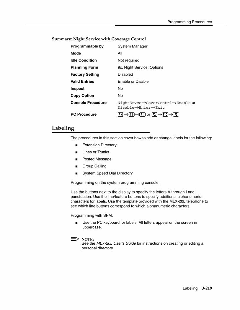
Programming Procedures
Labeling 3-219
Summary: Night Service with Coverage Control 3
Programmable by System Manager
Mode All
Idle Condition Not required
Planning Form 9c, Night Service: Options
Factory Setting Disabled
Valid Entries Enable or Disable
Inspect No
Copy Option No
Console Procedure NightSrvce→CoverContrl→Enable or Disable→Enter→Exit
PC Procedure �→ →� or �→�→�
Labeling 3
The procedures in this section cover how to add or change labels for the following:
� Extension Directory
� Lines or Trunks
� Posted Message
� Group Calling
� System Speed Dial Directory
Programming on the system programming console:
Use the buttons next to the display to specify the letters A through I and punctuation. Use the line/feature buttons to specify additional alphanumeric characters for labels. Use the template provided with the MLX-20L telephone to see which line buttons correspond to which alphanumeric characters.
Programming with SPM:
� Use the PC keyboard for labels. All letters appear on the screen in uppercase.
NOTE:See the MLX-20L User’s Guide for instructions on creating or editing a personal directory.

System Programming
3-220 Labeling
Extension Directory 3
Use this procedure to establish alphanumeric system labels for display telephone users to identify the person calling or leaving a message. This procedure is also used to program the Extension Directory feature for MLX telephones.
NOTES:In Release 6.0 and later systems (Hybrid/PBX mode only) where private networked systems are connected by PRI tandem trunks, programmed labels for extensions on the remote system may be displayed at a call recipient’s MLX display telephone on a local system. If other types of trunks connect the private network systems, the call display is the same as for an outside call. For additional information about controlling the display for such incoming calls, see ‘‘Display Preference’’ on page 3-133.
A label can have a maximum of seven characters.
Summary: Extension Directory 3
Programmable by System Manager
Mode All
Idle Condition Not required
Planning Form 2a, System Numbering: Extension Jacks
Factory Setting Not applicable
Valid Entries Not applicable
Inspect No
Copy Option
No
Console Procedure More→Labeling→Directory→Extension→Dial ext. no.→Enter→Drop→Enter label→ Enter→Exit→Exit→Exit
PC Procedure �→�→�→�→Type ext. no.→�→� + �→Type label→→�→�→�

Programming Procedures
Labeling 3-221
Lines or Trunks 3
Use this procedure to establish alphanumeric system labels for display telephone users to identify the line or trunk being used.
Summary: Lines or Trunks 3
Programmable by System Manager
Mode All
Idle Condition Not required
Planning Form 2c, System Numbering: Line/Trunk Jacks
Factory Setting Not applicable
Valid Entries Not applicable
Inspect No
Copy Option No
Console Procedure More→Labeling→LinesTrunks→Dial line/trunk no.→Enter→Drop→Dial label→Enter→ Exit→Exit
PC Procedure �→�→�→Type line/trunk no.→�→� + �→Type label→→�→�
Posted Message 3
Use this procedure to add or change existing posted messages. The posted messages allow callers with display telephones to know why the called extension does not answer.
Each posted message can have a maximum of 16 characters. Messages 2 through 20 can be changed through programming. Message 1, Do Not Disturb, cannot be changed.
NOTE:In Release 6.0 and later systems, posted messages are not supported across private network systems.

System Programming
3-222 Labeling
Summary: Posted Messages 3
Programmable by System Manager
Mode All
Idle Condition Not required
Planning Form 8a, Label Form: Posted Message
Factory Setting First 10 messages
Valid Entries 1 to 20
Inspect No
Copy Option No
Console Procedure More→Labeling→PostMessage→Dial message no. (1–20)→Enter→Drop→Enter message→ Enter→Exit→Exit
PC Procedure �→�→�→Type message no. (1–20)→�→� + �→Type message→→�→�
Group Calling 3
Use this procedure to establish alphanumeric system labels for display telephone users to identify calling groups.
A label can have a maximum of seven characters.
Summary: Group Calling 3
Programmable by System Manager
Mode All
Idle Condition Not required
Planning Form 6e, Group Calling
Factory Setting Not applicable
Valid Entries Not applicable
Inspect No
Copy Option No
Console Procedure More→Labeling→Grp Calling→Dial calling group ext. no.→Enter→Drop→Enter label→Enter→Exit→Exit
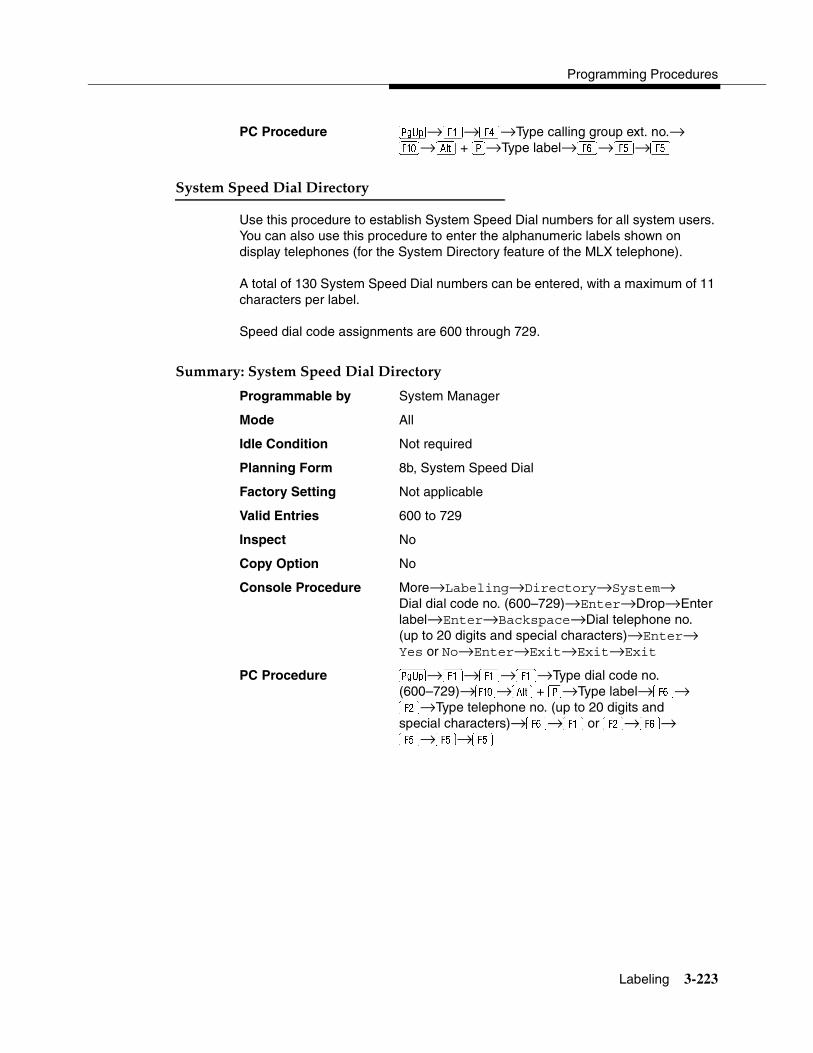
Programming Procedures
Labeling 3-223
PC Procedure �→�→→Type calling group ext. no.→�→� + �→Type label→→�→�
System Speed Dial Directory 3
Use this procedure to establish System Speed Dial numbers for all system users. You can also use this procedure to enter the alphanumeric labels shown on display telephones (for the System Directory feature of the MLX telephone).
A total of 130 System Speed Dial numbers can be entered, with a maximum of 11 characters per label.
Speed dial code assignments are 600 through 729.
Summary: System Speed Dial Directory 3
Programmable by System Manager
Mode All
Idle Condition Not required
Planning Form 8b, System Speed Dial
Factory Setting Not applicable
Valid Entries 600 to 729
Inspect No
Copy Option No
Console Procedure More→Labeling→Directory→System→Dial dial code no. (600–729)→Enter→Drop→Enter label→Enter→Backspace→Dial telephone no.(up to 20 digits and special characters)→Enter→ Yes or No→Enter→Exit→Exit→Exit
PC Procedure �→�→�→�→Type dial code no.(600–729)→�→� + �→Type label→→ �→Type telephone no. (up to 20 digits andspecial characters)→→� or �→→ �→�→�

System Programming
3-224 Print Reports
Print Reports 3
Use the procedures in this section to change the language for system reports and to print the system reports.
Report Language 3
Use this procedure to change the language of the system reports. It applies to Release 1.1 or later. Unless you change the report language, reports are printed in the language chosen as the system language.
Summary: Report Language 3
Programmable by System Manager
Mode All
Idle Condition Not required
Planning Form 1, System Planning
Factory Setting English
Valid Entries English, French, Spanish
Inspect No
Copy Option No
Console Procedure More→Language→Printer→English or French or Spanish→Enter→Exit
PC Procedure �→→→� or � or �→�→�
Printing System Reports 3
The communications system can be used to print a variety of reports. You can print individual reports or use the All option to print the entire set of available reports, including all report sections and options. See Appendix F for samples of the print reports.
Use this procedure to print the reports listed below. With the exception of Trunk Information, the dash lists under the bullets show the sections of each report that automatically print when the report option is selected.
� All
— Each report
— All report options
� System Set Up
Programming Procedures
Print Reports 3-225
� System Dial Plan
— Pools
— Telephone Paging Zones
— Direct Group Calling
— Lines/Trunks
— Stations (Extensions)
� Label Information
— Telephone Personal Directory
— Message Numbers and Posted Messages
� Trunk Information1
— TIE
— DID
— Loop/Ground
— General
— Switched 56 Data
� T1 Information
� PRI Information
� Remote Access
— General Options
— Non-TIE Restrictions
— TIE Restrictions
— Barrier Code Restrictions
� Operator Information
— Position
— General Options
— DSS Options
— QCC Operators
— Operator Information
� Allowed Lists
1 Trunk option must be specified

System Programming
3-226 Print Reports
� Allowed Lists Assigned to Extensions
� Disallowed Lists
� Disallowed Lists Assigned to Extensions
� Automatic Route Selection
� Tables
� Extension Directory
� System Directory
� Group Page
� Extension Information
� Group Coverage
� Group Calling
� Night Service
� Call Pickup Groups
� Error Logs
� Authorization Codes
� BRI Information Report
� Non-Local Dial Plan
� Service Observing Groups
NOTE:If you select the All option, keep in mind that the reports take from 30 minutes to 6 hours to print depending on the size of the system. You may want to schedule use of the printer during off-peak hours.
If you select a report for which there is no information, the report header still prints.
Print reports if you cannot back up your system programming information.
Do not print reports if your system must handle more than 100 calls per hour.
If you are printing from the console, your printer must be connected to the SMDR port. If you are programming on a PC with SPM, you have the following choices:
� Print reports on the SMDR printer (if available).
� Print reports on the PC printer.
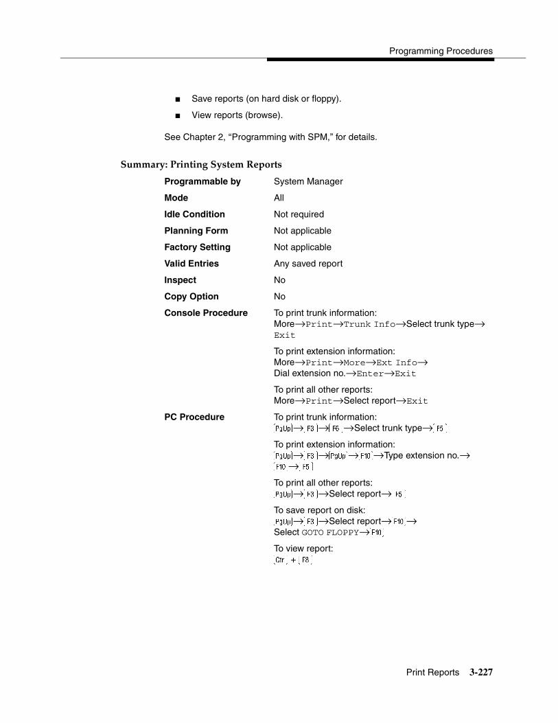
Programming Procedures
Print Reports 3-227
� Save reports (on hard disk or floppy).
� View reports (browse).
See Chapter 2, ‘‘Programming with SPM,” for details.
Summary: Printing System Reports 3
Programmable by System Manager
Mode All
Idle Condition Not required
Planning Form Not applicable
Factory Setting Not applicable
Valid Entries Any saved report
Inspect No
Copy Option No
Console Procedure To print trunk information:More→Print→Trunk Info→Select trunk type→ Exit
To print extension information:More→Print→More→Ext Info→Dial extension no.→Enter→Exit
To print all other reports:More→Print→Select report→Exit
PC Procedure To print trunk information:�→�→→Select trunk type→�
To print extension information:�→�→�→�→Type extension no.→ �→�To print all other reports:�→�→Select report→�
To save report on disk:�→�→Select report→�→Select GOTO FLOPPY→�
To view report:� + �
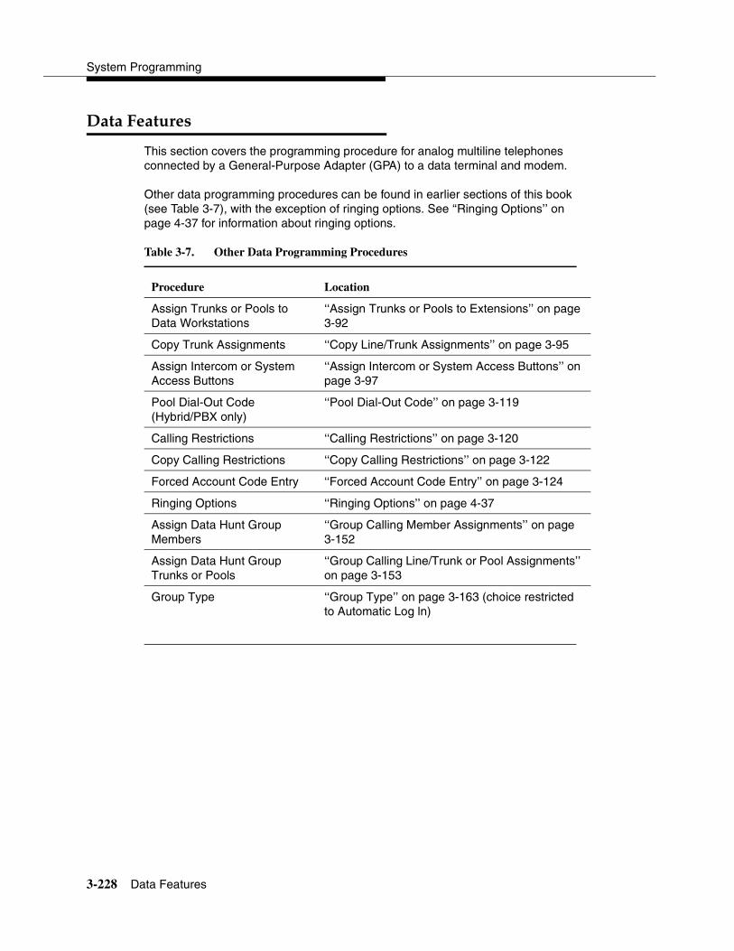
System Programming
3-228 Data Features
Data Features 3
This section covers the programming procedure for analog multiline telephones connected by a General-Purpose Adapter (GPA) to a data terminal and modem.
Other data programming procedures can be found in earlier sections of this book (see Table 3-7), with the exception of ringing options. See ‘‘Ringing Options’’ on page 4-37 for information about ringing options.
Table 3-7. Other Data Programming Procedures
Procedure Location
Assign Trunks or Pools to Data Workstations
‘‘Assign Trunks or Pools to Extensions’’ on page 3-92
Copy Trunk Assignments ‘‘Copy Line/Trunk Assignments’’ on page 3-95
Assign Intercom or System Access Buttons
‘‘Assign Intercom or System Access Buttons’’ on page 3-97
Pool Dial-Out Code(Hybrid/PBX only)
‘‘Pool Dial-Out Code’’ on page 3-119
Calling Restrictions ‘‘Calling Restrictions’’ on page 3-120
Copy Calling Restrictions ‘‘Copy Calling Restrictions’’ on page 3-122
Forced Account Code Entry ‘‘Forced Account Code Entry’’ on page 3-124
Ringing Options ‘‘Ringing Options’’ on page 4-37
Assign Data Hunt Group Members
‘‘Group Calling Member Assignments’’ on page 3-152
Assign Data Hunt Group Trunks or Pools
‘‘Group Calling Line/Trunk or Pool Assignments’’ on page 3-153
Group Type ‘‘Group Type’’ on page 3-163 (choice restricted to Automatic Log ln)

Programming Procedures
Data Features 3-229
Analog Multiline Telephones at Data Workstations 3
Use this procedure to dedicate a pair of extension jacks to provide the voice and data to an analog data workstation.
The extension number associated with the first (odd-numbered) extension jack in the pair is the telephone’s extension number. The extension number for the second (even-numbered) extension jack is dedicated to Data.
Calls cannot be placed to the extension jack reserved for data.
The Voice Announce feature must be disabled at data workstations.
When you select Enter after entering the voice extension number in the data entry screen, the system automatically assigns the data extension.
Use the Inspect feature to verify extension pairs.
Summary: Analog Multiline Telephones at Data Workstations 3
Programmable by System Manager
Mode All
Idle Condition System idle
Planning Form 2a, System Numbering: Extension Jacks 4b, Analog Multiline Telephone5a, Direct-Line Console (DLC): Analog DataData Form 2a, Analog Data Workstation
Factory Setting Not applicable
Valid Entries Extension numbers of analog sets
Inspect Yes
Copy Option Yes
Console Procedure More→Data→Voice/Data→Dial ext. no.→ Enter→Exit
PC Procedure �→�→�→Type ext. no.→�→�
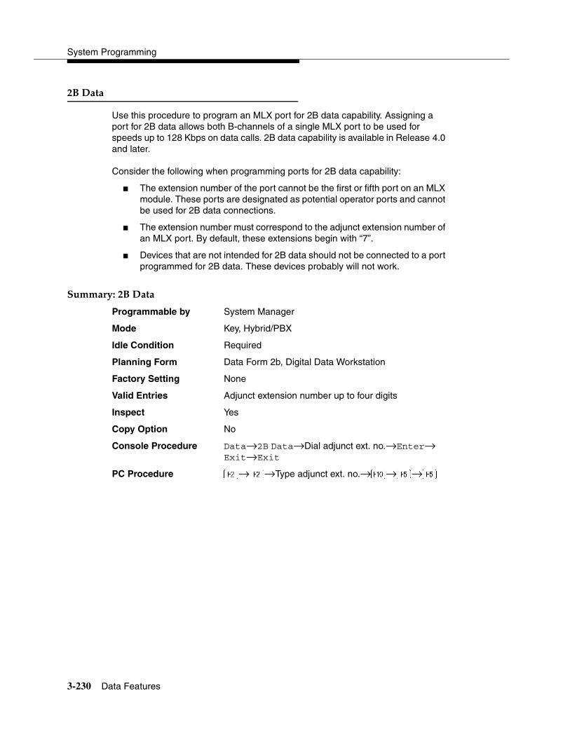
System Programming
3-230 Data Features
2B Data 3
Use this procedure to program an MLX port for 2B data capability. Assigning a port for 2B data allows both B-channels of a single MLX port to be used for speeds up to 128 Kbps on data calls. 2B data capability is available in Release 4.0 and later.
Consider the following when programming ports for 2B data capability:
� The extension number of the port cannot be the first or fifth port on an MLX module. These ports are designated as potential operator ports and cannot be used for 2B data connections.
� The extension number must correspond to the adjunct extension number of an MLX port. By default, these extensions begin with “7”.
� Devices that are not intended for 2B data should not be connected to a port programmed for 2B data. These devices probably will not work.
Summary: 2B Data 3
Programmable by System Manager
Mode Key, Hybrid/PBX
Idle Condition Required
Planning Form Data Form 2b, Digital Data Workstation
Factory Setting None
Valid Entries Adjunct extension number up to four digits
Inspect Yes
Copy Option No
Console Procedure Data→2B Data→Dial adjunct ext. no.→Enter→ Exit→Exit
PC Procedure �→�→Type adjunct ext. no.→�→�→�
Programming Procedures
Memory Card 3-231
Memory Card 3
A PCMCIA (Personal Computer Memory Card International Association) interface slot is present on the processor module. The slot is a standard interface through which information can be added to or obtained from the system using a memory card. The PCMCIA interface slot accepts one memory card at a time.
This section covers the following memory card functions:
� Memory Card Formatting
� Backup
� Automatic Backup
� Restore
Card Types 3
The types of memory cards are described below. The card type is identified by a preprinted, color-coded label.
� Upgrade Card. This card is used for MERLIN LEGEND Communications System software upgrades. The upgrade can be performed by the system manager using the memory card and the Maintenance option on the SPM main menu. See Maintenance and Troubleshooting for information about this feature.
This card is identified by an orange label with black lettering.
� Translation Card. The backup and restore procedures previously available to system managers through SPM (using the PC and floppy disks) can now be performed using the memory card and the new Backup/Restore option on the System menu. A new automatic backup feature permits you to set the system to perform automatic backups to the memory card on a daily or weekly basis. See ‘‘Backup’’ on page 3-236 and ‘‘Restore’’ on page 3-241 for more information.
This card is identified by a white label with black lettering.
� Forced Installation. For use by qualified service technicians only, this card is used when the system software has been corrupted and a re-installation must be done at the customer site. The use of the card for forced installation is reserved for emergency situations in which the system software on the processor module has been damaged.
This card is identified by an orange label with black lettering. In addition, black stripes are present on the card to distinguish it from an upgrade card.

System Programming
3-232 Memory Card
Figure 3-4 shows a sample Translation card.
Figure 3-4. PCMCIA Memory Card
LUCENT TECHNOLOGIES PROPRIETARYTHIS MEMORY CARD CONTAINS PROPRIETARY INFORMATION OF
LUCENT TECHNOLOGIES THAT IS NOT TO BE DISCLOSED OR USED EXCEPT IN ACCORDANCE WITH APPLICABLE AGREEMENTS.
COPYRIGHT© 1993 LUCENT TECHNOLOGIESALL RIGHTS RESERVED
INSERT
ME
RL
IN L
egen
d®
Tra
nsl
atio
n C
ard
CO
M c
od
e 1
2345
6789
MF
R 0
0DR
00
Fo
ur
(4)
Meg
abyt
es
• Do
not d
rop,
ben
d or
cru
sh• K
eep
away
from
moi
stur
e• K
eep
conn
ecto
r cle
an• A
void
hig
h te
mpe
ratu
res
and
dire
ct
sunl
ight
MEM
O
CAU
TIO
N
Rel
ease
3.5
Wri
te p
rote
ct

Programming Procedures
Memory Card 3-233
Inserting the Card 3
To insert the card, hold the card with the Lucent logo facing up and the arrow pointing toward the slot. See Figure 3-5 for the proper way to insert the memory card into the slot on the processor module.
Figure 3-5. Inserting the Memory Card
INSERT
COPYRIGHT© 1993 AT&T
ALL RIGHTS RESERVED
AT&T PROPRIETARY
THIS MEMORY CARD CONTAINS PROPRIETARY INFORMATION OF
AT&T THAT IS NOT TO BE DISCLOSED OR USED EXCEPT
IN ACCORDANCE WITH APPLICABLE AGREEMENTS.
PCMCIAInterface Slot
Error/Status CodeDisplay
MemoryCard
Push into remove
MemoryCard
PROCESSORMODULE
Alarm StatusLED
ME
RL
IN L
eg
en
d®
Fo
rced
In
sta
llati
on
S
N 0
0D
R 0
0000004
123456789
Fo
ur
(4)
Meg
ab
yte
s…
PR
OP
ER
TY
OF
AT
&T
…

System Programming
3-234 Memory Card
Memory Card Formatting 3
The memory card may have to be formatted before you begin any manual or automatic backup procedures. This section details the screens and messages that appear during the format procedure.
! CAUTION:Formatting overwrites previous data on the memory card. Make certain that there is no important information on the card before you begin formatting.
Unformatted Card 3
If you begin a backup procedure with an unformatted or incorrectly formatted card, the above screen appears.
The inserted memory card is not the correct type. You have the option of formatting the memory card as a translation memory card or repeating the backup procedure with a different memory card.
NOTES:� Only 4 MB Series I or Series II PCMCIA memory cards may be
formatted, except those already formatted as translation cards.
� If a memory card cannot be formatted, a message appears on screen. These messages are noted in the procedures as appropriate.
� A memory card may need to be formatted if it is intended for use as a translation card but is currently blank or contains data other than MERLIN LEGEND Communications System backup files.
Memory Card Backup:
Inserted Memory Card is
not the correct type.
Do you want it formatted?
Yes
No
Exit
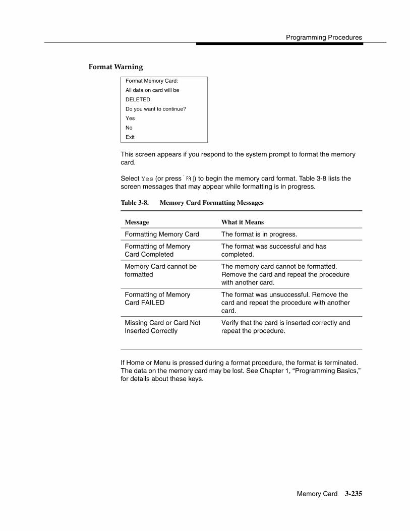
Programming Procedures
Memory Card 3-235
Format Warning 3
This screen appears if you respond to the system prompt to format the memory card.
Select Yes (or press �) to begin the memory card format. Table 3-8 lists the screen messages that may appear while formatting is in progress.
If Home or Menu is pressed during a format procedure, the format is terminated. The data on the memory card may be lost. See Chapter 1, ‘‘Programming Basics,” for details about these keys.
Format Memory Card:
All data on card will be
DELETED.
Do you want to continue?
Yes
No
Exit
Table 3-8. Memory Card Formatting Messages
Message What it Means
Formatting Memory Card The format is in progress.
Formatting of MemoryCard Completed
The format was successful and has completed.
Memory Card cannot beformatted
The memory card cannot be formatted. Remove the card and repeat the procedure with another card.
Formatting of Memory Card FAILED
The format was unsuccessful. Remove the card and repeat the procedure with another card.
Missing Card or Card Not Inserted Correctly
Verify that the card is inserted correctly and repeat the procedure.

System Programming
3-236 Memory Card
Backup 3
Use this procedure to make a copy of your customized system data. You should create a backup at least three times during system installation (so that programmed information is not lost) and once after each system upgrade, service technician visit, or major system reconfiguration.
The Inspect feature (Inspct or�) is available to view the attributes of the backup files on the memory card prior to initiating the backup procedure. The attributes included on the Inspect screen are the filename, the time and date of the file creation/update, the location of the system programming port, and information about the system software release from which the backup was made.
The list of backup files contains three manual backup filenames and two automatic backup filenames. The factory set names of the manual backup files are BACK1.*****, BACK2.*****, and BACK3.*****. When you select one of the backup filenames, the system automatically replaces the * in the filename with the current month and day (mmdd). For example, BACK1.0116 would appear if you selected BACK1.***** and performed the backup procedure on January 16. You can rename any of the three files during the backup procedure. The automatic backup filenames are AUTO.BACK1 and AUTO.BACK2. You cannot change the names of these files.
If you enter a filename that currently exists, the message File already exists appears. You must enter another filename.
While the backup is in progress, you cannot access system programming functions, your Personal Directory, or alarm clock functions (any programmed alarms are temporarily deactivated). You may terminate the backup procedure at any point prior to receiving confirmation of a successful backup.
If any type of programming is taking place at another extension when you begin the backup procedure, the backup is canceled and the number of the first busy extension appears on the screen. Attempt the backup procedure again when the busy extension becomes idle.
If the system is turned off during a backup procedure, the backup is terminated. The system performs a System Reset (cold start), after which you may repeat the backup procedure.
If Home or Menu is pressed during a backup procedure, the backup is terminated. This may result in the deletion of an old backup file. See Chapter 1, ‘‘Programming Basics,” for details about these keys.

Programming Procedures
Memory Card 3-237
NOTE:If the system performs a System Erase (frigid start), all programming is set to the factory-set values. If a previous backup file is available, perform a restore. If not, the system must be reprogrammed. See ‘‘Restore’’ on page 3-241 for information about the system restore procedure. Also see ‘‘Backup Messages’’ on page 3-239 for information about errors that may occur during the backup procedure.
Summary: Backup 3
Programmable by System Manager
Mode All
Idle Condition Not required (No extensions are allowed to be in programming mode except system programming console)
Planning Form 1, System Planning
Factory Setting Not applicable
Valid Entries 1- to 11-character filename
Inspect Yes
Copy Option No
Console Procedure Insert memory card→System→Back/Restore→ Backup→Select backup file→Dial the new backup filename→Enter→Yes→Exit→Exit→Exit
PC Procedure Insert memory card→�→ →�→Select backup file→Type the new backup filename→ →�→�→�→�
Automatic Backup 3
To preserve the most recent copy of your customized system data, you can program the system to automatically backup programming information onto the translation memory card. Automatic backups may be set for daily or weekly operation. If automatic backup is activated, the time may be set for daily backup (factory setting is 2:00 am) or the time and day may be set for weekly backup (factory setting is 2:00 am Sunday).
The system places the automatic backup into one of two designated files: AUTO.BACK1 and AUTO.BACK2. If both files are empty, the system places the backup in AUTO.BACK1. If both files already contain backups, the system selects the older of the two files and overwrites it. The system performs this file “toggle” each time it performs an automatic backup.
System Programming
3-238 Memory Card
While the backup is in progress, you cannot access system programming functions, your Personal Directory, or alarm clock functions (any programmed alarms are temporarily deactivated).
If any type of programming is taking place at an extension during the automatic backup procedure, the backup is canceled. The system does not re-attempt the backup.
If an automatic backup fails for any reason (including a system-busy condition), all of the programmed alarm buttons on system operator consoles light and the information is recorded in both the permanent error log and the last 10 error logs. The system does not re-attempt the backup.
Also see ‘‘Backup Messages’’ on page 3-239 for information about errors that may occur during the automatic backup procedure.
NOTE:If an automatic backup fails for any reason (except when the failure results because the memory card is write-protected), the automatic backup feature is turned off. Follow the procedure below to reprogram automatic backups.
Summary: Automatic Backup 3
Programmable by System Manager
Mode All
Idle Condition Not required (No extensions are allowed to be in programming mode, including the system programming console)
Planning Form 1, System Planning
Factory Setting Weekly backup: Sunday at 2:00 am(if daily backup is selected, time is factory set for 2:00 am)
Valid Entries Daily: hhmm (00 to 23; 00 to 59)Weekly: dhhmm (0 to 6; 00 to 23; 00 to 59)
Inspect No
Copy Option No
Console Procedure To program daily backup:Insert memory card→System→Back/Restore→Auto Backup→Daily→Drop→Dial time (00–23; 00–59)→Enter→Exit→Exit
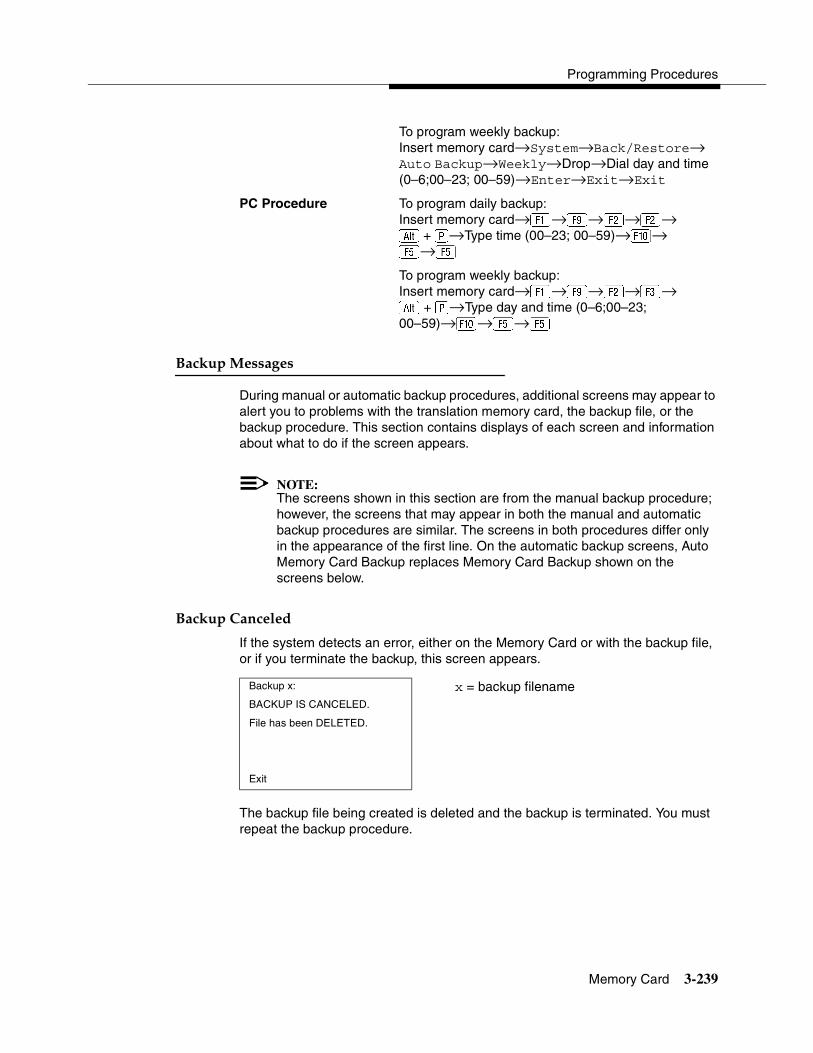
Programming Procedures
Memory Card 3-239
To program weekly backup:Insert memory card→System→Back/Restore→Auto Backup→Weekly→Drop→Dial day and time (0–6;00–23; 00–59)→Enter→Exit→Exit
PC Procedure To program daily backup:Insert memory card→�→ →�→�→� + �→Type time (00–23; 00–59)→�→ �→�To program weekly backup:Insert memory card→�→ →�→�→� + �→Type day and time (0–6;00–23; 00–59)→�→�→�
Backup Messages 3
During manual or automatic backup procedures, additional screens may appear to alert you to problems with the translation memory card, the backup file, or the backup procedure. This section contains displays of each screen and information about what to do if the screen appears.
NOTE:The screens shown in this section are from the manual backup procedure; however, the screens that may appear in both the manual and automatic backup procedures are similar. The screens in both procedures differ only in the appearance of the first line. On the automatic backup screens, Auto Memory Card Backup replaces Memory Card Backup shown on the screens below.
Backup Canceled 3
If the system detects an error, either on the Memory Card or with the backup file, or if you terminate the backup, this screen appears.
The backup file being created is deleted and the backup is terminated. You must repeat the backup procedure.
Backup x: x = backup filename BACKUP IS CANCELED.
File has been DELETED.
Exit
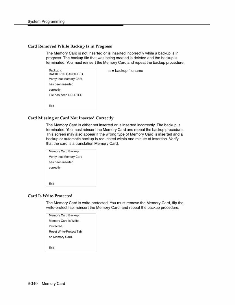
System Programming
3-240 Memory Card
Card Removed While Backup Is in Progress 3
The Memory Card is not inserted or is inserted incorrectly while a backup is in progress. The backup file that was being created is deleted and the backup is terminated. You must reinsert the Memory Card and repeat the backup procedure.
Card Missing or Card Not Inserted Correctly 3
The Memory Card is either not inserted or is inserted incorrectly. The backup is terminated. You must reinsert the Memory Card and repeat the backup procedure. This screen may also appear if the wrong type of Memory Card is inserted and a backup or automatic backup is requested within one minute of insertion. Verify that the card is a translation Memory Card.
Card Is Write-Protected 3
The Memory Card is write-protected. You must remove the Memory Card, flip the write-protect tab, reinsert the Memory Card, and repeat the backup procedure.
Backup x:BACKUP IS CANCELED.
x = backup filename
Verify that Memory Card
has been inserted
correctly.
File has been DELETED.
Exit
Memory Card Backup:
Verify that Memory Card
has been inserted
correctly.
Exit
Memory Card Backup:
Memory Card is Write-
Protected.
Reset Write-Protect Tab
on Memory Card.
Exit
Programming Procedures
Memory Card 3-241
! CAUTION:The Memory Card may be write-protected to avoid the accidental erasure of the backup files. Make certain this is not the case before you change the Write-Protect Tab.
Card Failure 3
If the card is damaged, repeat the backup with a different card. If a backup is in progress and fails, the system makes two additional attempts at the backup. At the start of each attempt, a message appears with the percentage of the backup that is completed. If the backup fails after three attempts, the screen shown below appears. Repeat the backup procedure using a different file and/or Memory Card.
Restore 3
Use this procedure to restore system conditions that were backed up onto a translation memory card. The information in a backup file on the translation card is copied to the system.
The restore procedure is necessary under the following conditions:
� System RAM is corrupt.
� A previously stored set of system conditions is preferred over the current set.
� Processor module is replaced.
� After a System Erase (frigid start) has been performed.
� System software has been reinstalled.
The Inspect feature (Inspct or�) is available to view the attributes of the backup files on the memory card prior to initiating the restore procedure. The attributes included on the Inspect screen are the filename, the time and day of the file creation/update, the location of the system programming port, and information about the system software release from which the backup was made.
If any type of programming is taking place at another extension when you begin the restore procedure, the restore is canceled and the number of the first busy
Memory Card Backup:
Backup Failure
Try a different file or
a new Memory Card.
Exit
System Programming
3-242 Memory Card
extension appears on the screen. Repeat the restore procedure when the busy extension becomes idle.
If a line is busy (incoming call or active call) when you begin the restore procedure, the restore is canceled and the number of the first active line appears on the screen. Repeat the restore procedure when the line becomes idle.
Also see ‘‘Restore Messages’’ on page 3-242 for information about errors that may occur during the restore procedure.
Summary: Restore 3
Programmable by System Manager
Mode All
Idle Condition System Forced Idle
Planning Form Not applicable
Factory Setting Not applicable
Valid Entries Not applicable
Inspect Yes
Copy Option No
Console Procedure Insert memory card→System→Back/Restore→ Restore→Select restore file→Yes
PC Procedure Insert memory card→�→ →�→Select restore file→�
Restore Messages 3
During the restore procedure, additional screens may appear to alert you to problems with the translation Memory Card, the backup file or the restore procedure. This section contains displays of each screen and information about what to do if the screen appears.
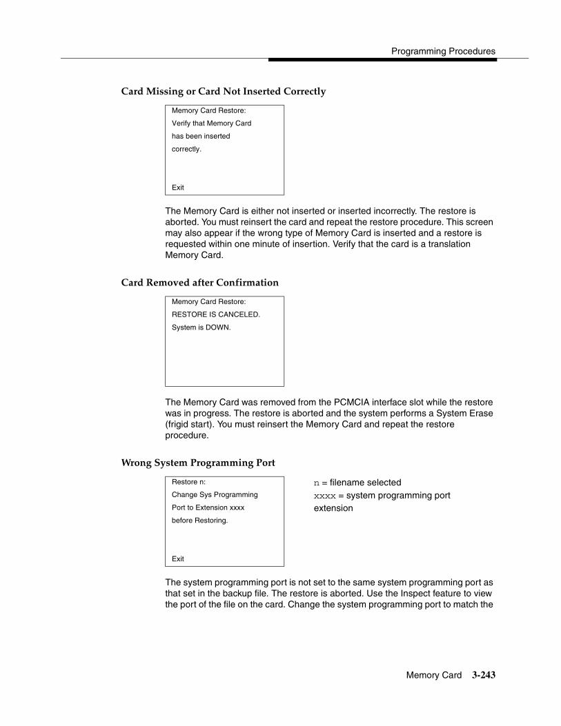
Programming Procedures
Memory Card 3-243
Card Missing or Card Not Inserted Correctly 3
The Memory Card is either not inserted or inserted incorrectly. The restore is aborted. You must reinsert the card and repeat the restore procedure. This screen may also appear if the wrong type of Memory Card is inserted and a restore is requested within one minute of insertion. Verify that the card is a translation Memory Card.
Card Removed after Confirmation 3
The Memory Card was removed from the PCMCIA interface slot while the restore was in progress. The restore is aborted and the system performs a System Erase (frigid start). You must reinsert the Memory Card and repeat the restore procedure.
Wrong System Programming Port 3
The system programming port is not set to the same system programming port as that set in the backup file. The restore is aborted. Use the Inspect feature to view the port of the file on the card. Change the system programming port to match the
Memory Card Restore:
Verify that Memory Card
has been inserted
correctly.
Exit
Memory Card Restore:
RESTORE IS CANCELED.
System is DOWN.
Restore n: n = filename selected Change Sys Programming xxxx = system programming port Port to Extension xxxx extensionbefore Restoring.
Exit

System Programming
3-244 Memory Card
port shown on the card (see ‘‘System Programming Position Assignment’’ on page 3-3) and repeat the restore procedure.
Release Mismatch 3
This screen only appears if you are upgrading from Release 3.0 or later and the releases are not compatible.
Card Failure Before Confirmation 3
If the restore fails because the card is damaged, repeat the restore procedure using a different file and/or Memory Card.
Card Failure after Confirmation 3
If the restore fails because the card is damaged, the system performs a System Erase (frigid start). Repeat the restore procedure using a different file and/or Memory Card.
Restore n: n = filename selectedFile is Not Compatible X.Y = release numberfor Release X.Y
Restore Canceled.
Conversion Required.
Exit
Memory Card Restore:
Restore Failure.
Try a different file
or a new Memory Card.
Exit
Restore n: n = filename selectedRestore Failure
RESTORE IS CANCELED.
System is DOWN.

Programming Procedures
Memory Card 3-245
Wrong Type of Card 3
The inserted card does not match the card option selected from the System menu. Remove the card and repeat the restore procedure with the correct type of card. See ‘‘Card Types’’ on page 3-231 for information about the card labels.
Board Mismatch 3
A mismatch exists between the hardware components present on the current system and the hardware components reflected in the backup file. The restore is aborted. You can do one of the following:
� Repeat the restore procedure with another file.
� Modify the system hardware to match the configuration of the backup file and repeat the restore procedure with the same file.
Memory Card Restore:
Inserted Memory Card is
not the correct type.
Remove and insert MERLIN
LEGEND Backup/Restore
Card.
Exit
Restore n: n = filename selectedRestore Failure
RESTORE IS CANCELED.
Board mismatch between
control unit and file.
Exit

System Programming
3-246 Memory Card
Strap in Place for Key Mode but Mode is Set to Hybrid 3
! CAUTION:This procedure should be performed only by qualified service personnel.
If the processor module has been set for Permanent Key mode, a restore to Hybrid/PBX mode is not possible. A service associate must be notified in order to modify the processor.
Restore n: n = filename selectedRestore Failure
RESTORE IS CANCELED.
Restore File Mode is
Hybrid/PBX. Control Unit
strap in place for KEY.
Exit

Contents
4-i
4Centralized Telephone Programming
Overview 4-1
Introduction 4-2
Access to Centralized Telephone Programming 4-3
Program Extension 4-4
� Programming Codes 4-6
� Using the List Feature Menu 4-11
Copy Extension 4-12
� Features That Can Be Copied 4-12
Feature Quick Reference 4-17
� Account Code Entry 4-17
Summary: Account Code Entry 4-17
� Alarm 4-18
Summary: Alarm 4-18
� Authorization Code 4-18
Summary: Authorization Code 4-18
� Auto Answer All 4-18
Summary: Auto Answer All 4-18
� Auto Answer Intercom 4-19
Summary: Auto Answer Intercom 4-19
� Auto Dial 4-19
Summary: Auto Dial Inside and Outside 4-19
� Automatic Line Selection 4-19
Summary: Automatic Line Selection 4-20
4-ii
Contents
System Programming
� Barge-In 4-20
Summary: Barge-In 4-20
� Callback 4-20
Summary: Automatic Callback 4-21
Summary: Selective Callback 4-21
� Caller Number and Name on Caller ID 4-21
Summary: Caller Number and Name 4-21
� Call Waiting 4-22
Summary: Call Waiting 4-22
� Camp-On 4-22
Summary: Camp-On 4-22
� Conference 4-23
Summary: Conference 4-23
� Coverage 4-23
Summary: Receiver Buttons–Primary, Secondary, Group 4-23
Summary: Coverage Inside Off/On 4-23
Summary: Sender Buttons, Coverage Off 4-24
Summary: Coverage VMS Off 4-24
� Data Status 4-24
Summary: Data Status 4-24
� Direct Voice Mail 4-25
Summary: Direct Voice Mail 4-25
� Do Not Disturb 4-25
Summary: Do Not Disturb 4-25
� Drop 4-25
Summary: Drop 4-25
� Extension Status 4-26
Summary: DLC Extension Status 4-26
Summary: Telephone Extension Status 1 and 2 4-26
� Feature Button 4-27
Summary: Feature Button 4-27
� Forward 4-27
Summary: Forward 4-27
4-iii
Contents
Centralized Telephone Programming
� Group Calling 4-27
Summary: Calls-In-Queue Alarm Button 4-27
� Calling Group Supervisor 4-28
Summary: Calling Group Supervisor 4-28
Summary: Calling Group Members 4-28
� Group Page Auto Dial Button 4-28
Summary: Group Page Auto Dial button 4-28
� Headset 4-29
Summary: Headset Auto Answer 4-29
Summary: Headset Hang Up 4-29
Summary: Headset Mute 4-29
Summary: Headset Status 4-30
� Last Number Dial 4-30
Summary: Last Number Dial 4-30
� Messaging 4-30
Summary: Leave Message After Calling 4-30
Summary: Leave Message–Message LED Off 4-31
Summary: Posted Message 4-31
Summary: Send/Remove Message 4-31
Summary: Receiving Messages–Delete 4-31
Summary: Receiving Messages–Next 4-32
Summary: Receiving Messages–Return Call 4-32
Summary: Receiving Messages–Scroll 4-32
� Night Service 4-32
Summary: Night Service 4-32
� Notify 4-33
Summary: Notify–Send and Receive 4-33
� Park 4-33
Summary: Park 4-33
� Park Zone Auto Dial 4-34
Summary: Park Zone Auto Dial 4-34
� Personal Speed Dial 4-34
Summary: Personal Speed Dial 4-34
� Pickup 4-34
4-iv
Contents
System Programming
Summary: Pickup–General Use,Specific Extension, Specific Line 4-34
� Privacy 4-35
Summary: Privacy 4-35
� Recall 4-35
Summary: Recall 4-35
� Reminder Service 4-36
Summary: Set, Cancel, or Missed Reminder Service 4-36
� Ringing/Idle Line Preference 4-36
Summary: Ringing and Idle Line Preference 4-36
� Ringing Options 4-37
Summary: Personalized Ringing 4-37
Summary: Ring Timing Options 4-37
Summary: Abbreviated Ringing Options 4-38
Summary: Send Ringing Options 4-38
� Saved Number Dial 4-38
Summary: Saved Number Dial 4-38
� Send/Remove Message 4-39
Summary: Send/Remove Message 4-39
� Service Observing 4-39
Summary: Service Observing 4-39
� Signaling 4-40
Summary: Signaling (manual) 4-40
� System Access/Intercom Buttons 4-40
Summary: Assign System Access/Intercom Buttons 4-40
Summary: Assign Shared System Access Buttons 4-41
Summary: Change Type of System Access Button 4-41
� System Speed Dial 4-41
Summary: System Speed Dial 4-41
� Transfer 4-42
Summary: Transfer 4-42
� Voice Announce 4-42
Summary: Voice Announce 4-42

Overview 4-1
4�������������� ���������������� 4
�������� 4
This chapter describes centralized telephone programming for the system manager and includes the following information:
� Accessing centralized telephone programming
� Programming the features available with this function
� Programming a single telephone
� Copying programmed features from one extension to another extension (Release 2.0 or later)
See the Feature Reference, or the appropriate user or operator guide for details about each feature.
NOTE:Only the system manager should perform the programming procedures described in this chapter.
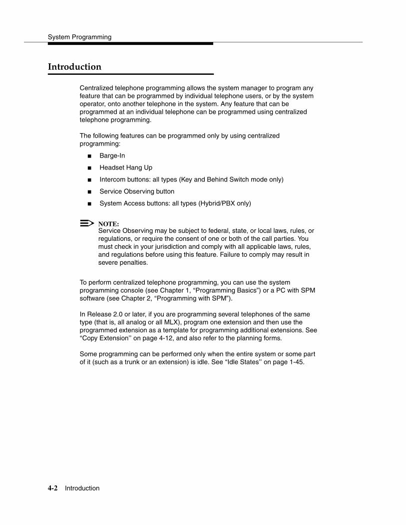
System Programming
4-2 Introduction
����������� 4
Centralized telephone programming allows the system manager to program any feature that can be programmed by individual telephone users, or by the system operator, onto another telephone in the system. Any feature that can be programmed at an individual telephone can be programmed using centralized telephone programming.
The following features can be programmed only by using centralized programming:
� Barge-In
� Headset Hang Up
� Intercom buttons: all types (Key and Behind Switch mode only)
� Service Observing button
� System Access buttons: all types (Hybrid/PBX only)
NOTE:Service Observing may be subject to federal, state, or local laws, rules, or regulations, or require the consent of one or both of the call parties. You must check in your jurisdiction and comply with all applicable laws, rules, and regulations before using this feature. Failure to comply may result in severe penalties.
To perform centralized telephone programming, you can use the system programming console (see Chapter 1, ‘‘Programming Basics”) or a PC with SPM software (see Chapter 2, ‘‘Programming with SPM”).
In Release 2.0 or later, if you are programming several telephones of the same type (that is, all analog or all MLX), program one extension and then use the programmed extension as a template for programming additional extensions. See ‘‘Copy Extension’’ on page 4-12, and also refer to the planning forms.
Some programming can be performed only when the entire system or some part of it (such as a trunk or an extension) is idle. See ‘‘Idle States’’ on page 1-45.
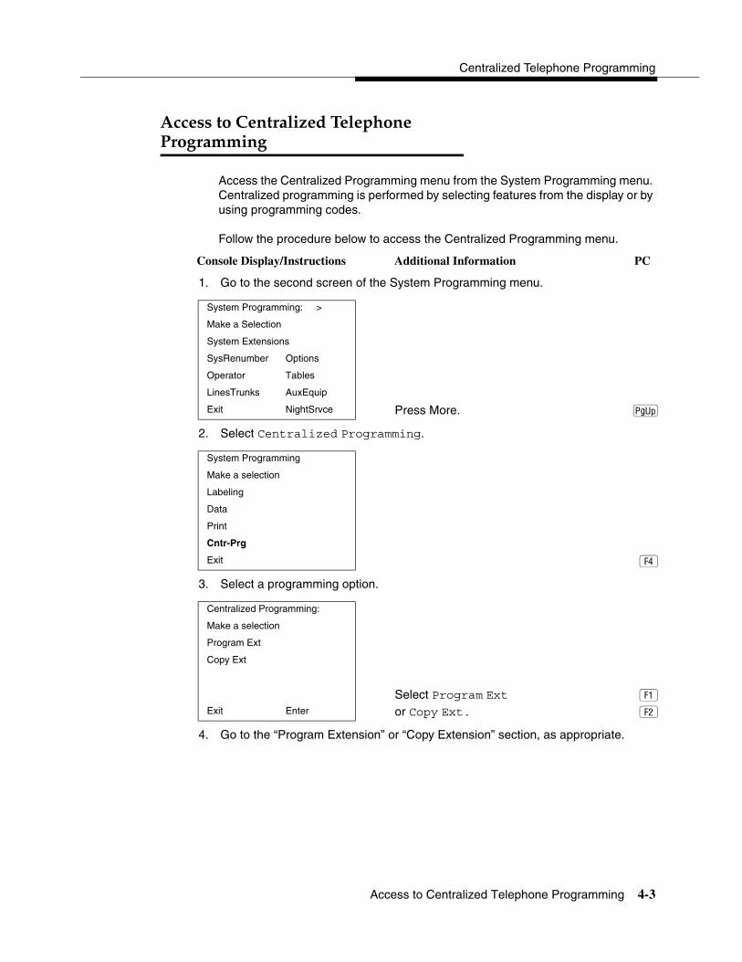
Centralized Telephone Programming
Access to Centralized Telephone Programming 4-3
������������������������ ���������������� 4
Access the Centralized Programming menu from the System Programming menu. Centralized programming is performed by selecting features from the display or by using programming codes.
Follow the procedure below to access the Centralized Programming menu.
Console Display/Instructions Additional Information PC
1. Go to the second screen of the System Programming menu.
2. Select Centralized Programming.
3. Select a programming option.
4. Go to the “Program Extension” or “Copy Extension” section, as appropriate.
System Programming: >
Make a Selection
System Extensions
SysRenumber Options
Operator Tables
LinesTrunks AuxEquip
Exit NightSrvce Press More. �
System Programming
Make a selection
Labeling
Data
Cntr-Prg
Exit �
Centralized Programming:
Make a selection
Program Ext
Copy Ext
Select Program Ext � Exit Enter or Copy Ext. �
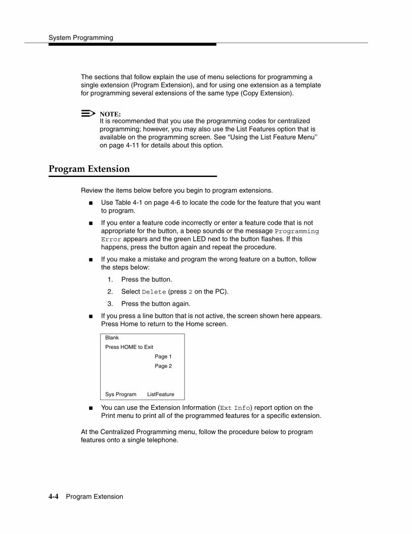
System Programming
4-4 Program Extension
The sections that follow explain the use of menu selections for programming a single extension (Program Extension), and for using one extension as a template for programming several extensions of the same type (Copy Extension).
NOTE:It is recommended that you use the programming codes for centralized programming; however, you may also use the List Features option that is available on the programming screen. See ‘‘Using the List Feature Menu’’ on page 4-11 for details about this option.
����������������� 4
Review the items below before you begin to program extensions.
� Use Table 4-1 on page 4-6 to locate the code for the feature that you want to program.
� If you enter a feature code incorrectly or enter a feature code that is not appropriate for the button, a beep sounds or the message Programming Error appears and the green LED next to the button flashes. If this happens, press the button again and repeat the procedure.
� If you make a mistake and program the wrong feature on a button, follow the steps below:
1. Press the button.
2. Select Delete (press 2 on the PC).
3. Press the button again.
� If you press a line button that is not active, the screen shown here appears. Press Home to return to the Home screen.
� You can use the Extension Information (Ext Info) report option on the Print menu to print all of the programmed features for a specific extension.
At the Centralized Programming menu, follow the procedure below to program features onto a single telephone.
Blank
Press HOME to Exit
Page 1
Page 2
Sys Program ListFeature
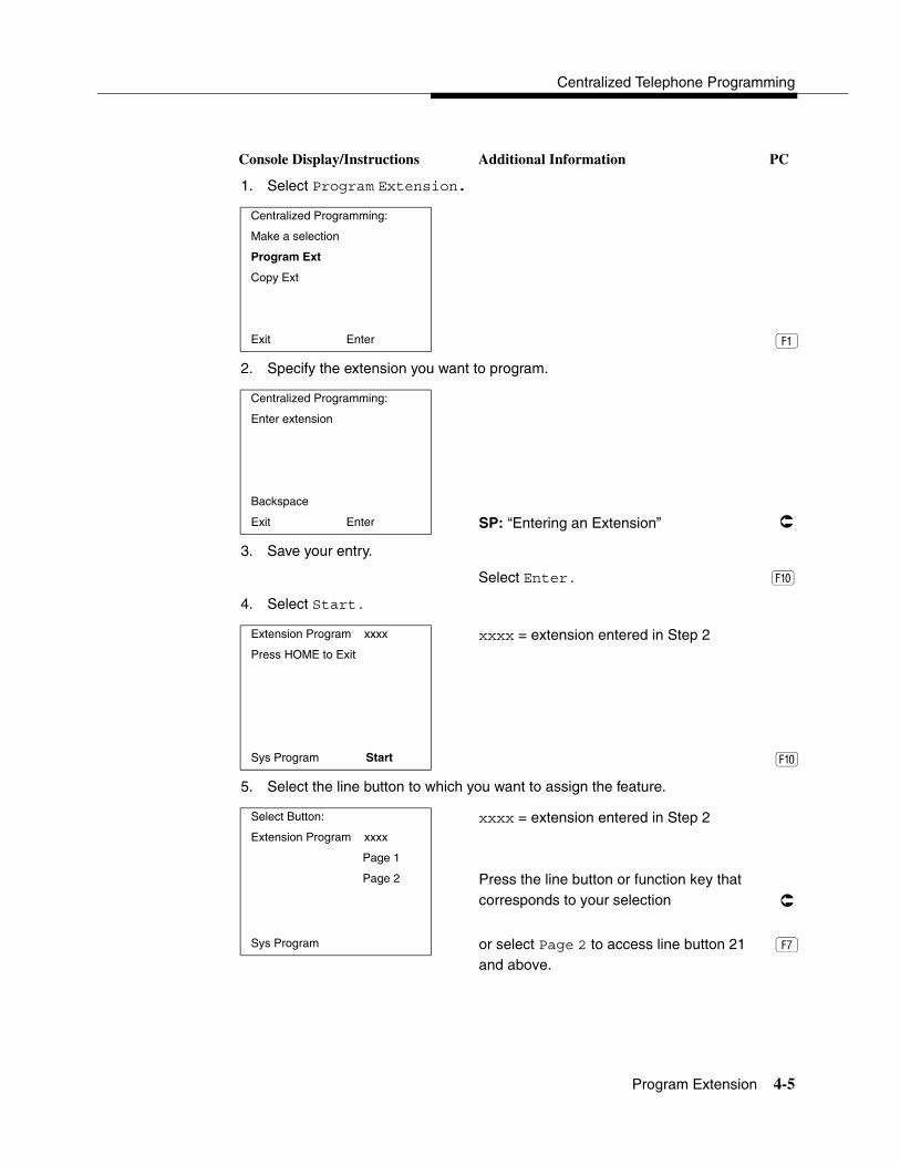
Centralized Telephone Programming
Program Extension 4-5
Console Display/Instructions Additional Information PC
1. Select Program Extension.
2. Specify the extension you want to program.
3. Save your entry.
Select Enter. �
4. Select Start.
5. Select the line button to which you want to assign the feature.
Centralized Programming:
Make a selection
Program Ext
Copy Ext
Exit Enter �
Centralized Programming:
Enter extension
Backspace
Exit Enter SP: “Entering an Extension” �
Extension Program xxxx xxxx = extension entered in Step 2Press HOME to Exit
Sys Program Start �
Select Button: xxxx = extension entered in Step 2Extension Program xxxx
Page 1
Page 2 Press the line button or function key thatcorresponds to your selection �
Sys Program or select Page 2 to access line button 21 �
and above.
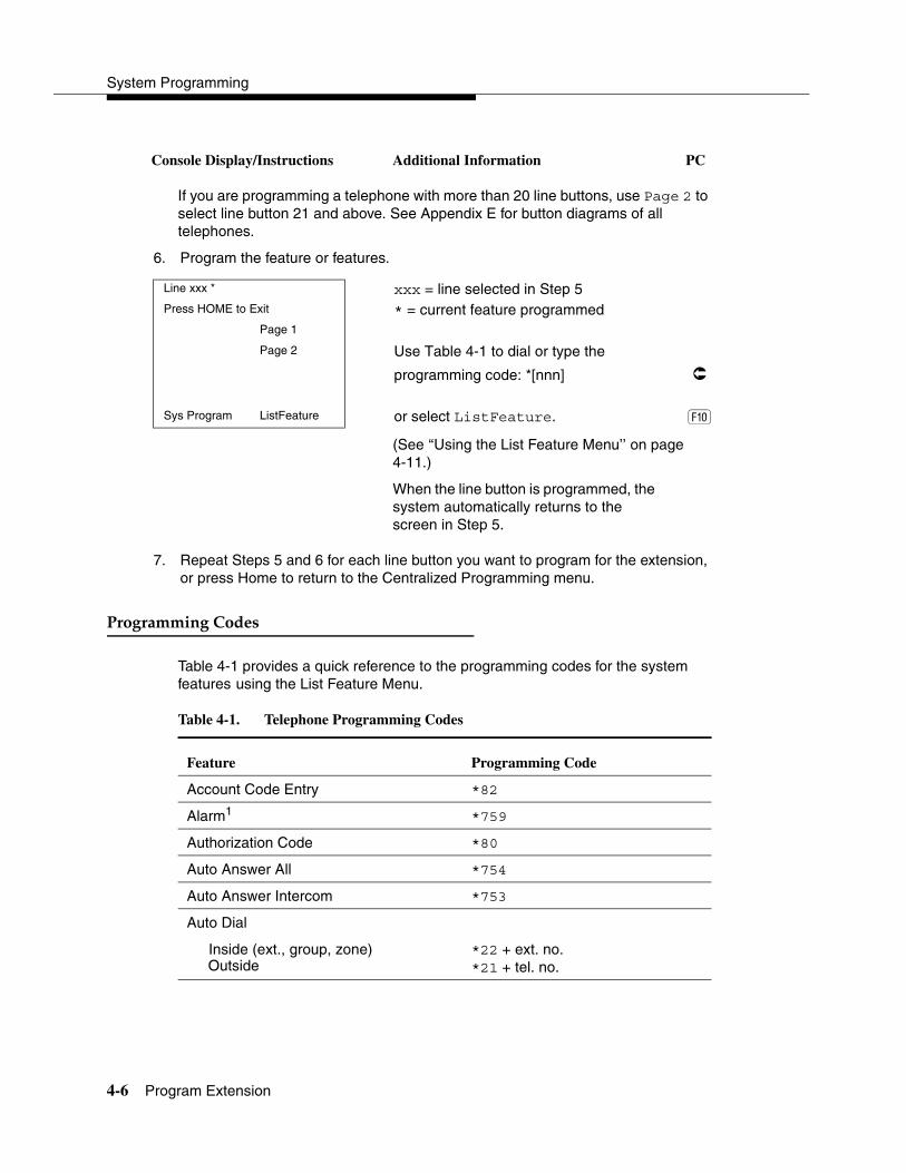
System Programming
4-6 Program Extension
Console Display/Instructions Additional Information PC
If you are programming a telephone with more than 20 line buttons, use Page 2 to select line button 21 and above. See Appendix E for button diagrams of all telephones.
6. Program the feature or features.
(See ‘‘Using the List Feature Menu’’ on page 4-11.)
When the line button is programmed, the system automatically returns to the screen in Step 5.
7. Repeat Steps 5 and 6 for each line button you want to program for the extension, or press Home to return to the Centralized Programming menu.
���������������� 4
Table 4-1 provides a quick reference to the programming codes for the system features using the List Feature Menu.
Line xxx * xxx = line selected in Step 5Press HOME to Exit * = current feature programmed
Page 1
Page 2 Use Table 4-1 to dial or type the
programming code: *[nnn] �
Sys Program ListFeature or select ListFeature. �
Table 4-1. Telephone Programming Codes
Feature Programming Code
Account Code Entry *82
Alarm1 *759
Authorization Code *80
Auto Answer All *754
Auto Answer Intercom *753
Auto Dial
Inside (ext., group, zone)Outside
*22 + ext. no.*21 + tel. no.

Centralized Telephone Programming
Program Extension 4-7
Automatic Line Selection
Begin SequenceEnd Sequence
*14**14
Barge-ln1, 2 *58
Callback
AutomaticOnOffSelective
*12**12*55
Caller ID (name/number toggle) *763
Call Waiting
OnOff
*11 **11
Camp-On *57
Conference *772
Coverage
Receiver buttonsGroupPrimarySecondary
Sender buttonsCover inside and outside callsCover outside calls onlyCoverage Off
Coverage VMS Off
*42 + ext. no.*40 + ext. no.*41 + ext. no.
*48**48*49
*46
Data Status *83 + ext. no.
Direct Voice Mail *56
Directories
Extension Directory Personal Directory System Directory
(display only)(display only)(sys. prog.)
Do Not Disturb *47
Drop *773
Table 4-1. Telephone Programming Codes—Continued
Feature Programming Code
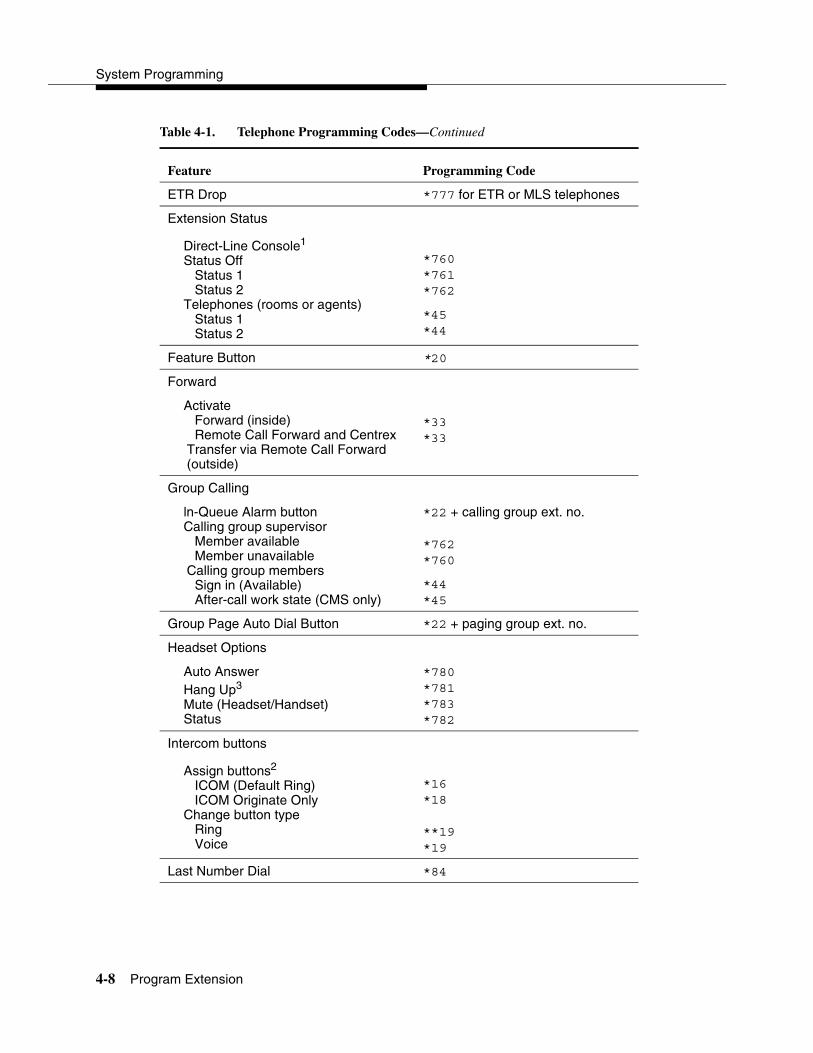
System Programming
4-8 Program Extension
ETR Drop *777 for ETR or MLS telephones
Extension Status
Direct-Line Console1
Status Off Status 1 Status 2Telephones (rooms or agents) Status 1 Status 2
*760*761*762
*45*44
Feature Button *20
Forward
Activate Forward (inside) Remote Call Forward and Centrex Transfer via Remote Call Forward (outside)
*33*33
Group Calling
ln-Queue Alarm buttonCalling group supervisor Member available Member unavailableCalling group members Sign in (Available) After-call work state (CMS only)
*22 + calling group ext. no.
*762*760
*44*45
Group Page Auto Dial Button *22 + paging group ext. no.
Headset Options
Auto Answer Hang Up3
Mute (Headset/Handset) Status
*780*781*783*782
Intercom buttons
Assign buttons2
ICOM (Default Ring) ICOM Originate Only Change button type Ring Voice
*16*18
**19*19
Last Number Dial *84
Table 4-1. Telephone Programming Codes—Continued
Feature Programming Code

Centralized Telephone Programming
Program Extension 4-9
Messaging
Leave MessageMessage LED off (for non-display
telephones)Message operation mode (for ETR,
MLS, and analog multiline display telephones)
*25*54
*54 (Used to enter/exit Message operation mode. MLS and analog multiline telephones return to normal call handling after 15 seconds if user has no messages; if these users have messages, they must delete them or use feature code or programmed button to exit Message operation. For ETR telephones, feature code or programmed button must be used to exit Message operation mode regardless of whether user has messages.)
Posted MessageSend/Remove Msg3
Receiving messages Delete Message3 Next Message3
Return Call3
Scroll3
*751*38
*26*28*27*29
Night Service1 *39
Notify
SendReceive
*757 + ext. no.*758 + ext. no.
Park *86
Park Zone Auto Dial4 *22 + park zone
Personal Speed Dial # + (01–24) +*21 + tel no. +##
Personalized Ringing *32 + ring (1–8)
Pickup
General useSpecific extensionSpecific lineGroup
*9*9 + ext. no.*9 + line no.*88
Table 4-1. Telephone Programming Codes—Continued
Feature Programming Code
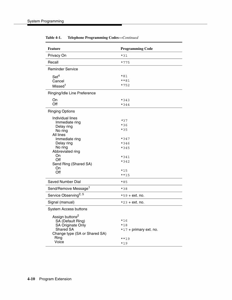
System Programming
4-10 Program Extension
Privacy On *31
Recall *775
Reminder Service
Set4
CancelMissed1
*81**81*752
Ringing/Idle Line Preference
OnOff
*343*344
Ringing Options
Individual lines Immediate ring Delay ring No ringAll lines Immediate ring Delay ring No ringAbbreviated ring On OffSend Ring (Shared SA) On Off
*37*36*35
*347*346*345
*341*342
*15**15
Saved Number Dial *85
Send/Remove Message1 *38
Service Observing2, 5 *59 + ext. no.
Signal (manual) *23 + ext. no.
System Access buttons
Assign buttons2
SA (Default Ring) SA Originate Only Shared SAChange type (SA or Shared SA) Ring Voice
*16*18*17 + primary ext. no.
**19*19
Table 4-1. Telephone Programming Codes—Continued
Feature Programming Code

Centralized Telephone Programming
Program Extension 4-11
����������������������� ��� 4
You can use the List Feature menu to select a feature, instead of using a programming code. When you select ListFeature (or press 0), the first screen of features appears as shown below.
There are additional feature option screens. Press More to move through the screens. Press the button or function key that corresponds to your selection. You can also use the FindFeature option to display alphabetized lists of features that begin with the letter or letters you select.
System Speed Dial *24 + code (600–729)
Transfer *774
Voice Announce
On Off VA on Idle Only6
*10**10*130
1 System operator feature only.
2 Centralized telephone programming only.
3 Display telephones only. Programming and feature codes are used with analog multiline telephones only.
4 English only: time is 12-hour (0100-1259) + 2 (A) or 7 (P); French and Spanish: time is 24-hour (000-2359).
5 MLX telephones only. Cannot be a QCC or CTI link.
6 MLX telephones only.
Select a Feature: >
Extension Program xxxx xxxx = previously entered extensionFind Feature Barge In
AccountCode Call Waiting
Auth Code Camp On
Auto Dial Cback Auto
AutoLineSel Cback Sel
Table 4-1. Telephone Programming Codes—Continued
Feature Programming Code

System Programming
4-12 Copy Extension
The Find Feature screen is shown below.
Press the button or function key that corresponds to the first letter of the feature you want. The resulting screen displays all of the features that begin with the selected letters. If the list of features for the letters you select does not fill a complete screen, the screen display continues with the next alphabetic feature. Press Home to return to the Home screen.
�� !���������� 4
The system manager uses the copy extension feature to copy an extension’s programmed buttons (with some exceptions) to one or more extensions. The features are individually programmed on an extension, creating a template that can then be copied to other extensions in the system.
Only extensions of the same type can be copied to one another (that is, analog to analog, and MLX to MLX) since the two extension types have different button layouts. For a system that has both analog and MLX telephone types, you will need two templates: one for analog and one for MLX.
An MFM can be copied to or from another MFM. A DLC can be copied only to another DLC. Single-line telephones and QCCs cannot be copied to or from.
������������������"���� �� 4
Table 4-2 lists the features that can be copied to another extension. Features that can be copied for DLC operator extensions are listed in Table 4-3 on page 4-15.
Choose Starting Letter
Press HOME to Exit
ABC PQRS
DEF TUV
GHI WXYZ
JKL
MNO

Centralized Telephone Programming
Copy Extension 4-13
Table 4-2. Features that Can Be Copied: All Telephones
FeatureAnalog
TelephonesMLX
Telephones MLS
Telephones ETR
Telephones
Account Code Entry � � � �
Authorization Code � � � �
Auto Answer All �
Auto Answer Intercom �
Auto Dial Inside � � � �
Auto Dial Outside1� � � �
Barge-In � � � �
Callback-Selective � � � �
Camp-On � � � �
Conference2� � � �
Coverage: Group � � � �
Coverage: Primary � � � �
Coverage Off � � � �
Coverage VMS Off � � � �
Data Status � � � �
Delete Message � � �
Direct Voice Mail � � � �
Do Not Disturb � � � �
Drop � � � �
ETR Drop � �
Extension Status 2 (ES2) (Non-operator)
� � � �
Extension Status 1 (ES1) (Non-operator)
� � � �
Feature Button �
Forward � � � �

System Programming
4-14 Copy Extension
Group Calling � � � �
Group Page � � � �
Headset Auto Answer �
Headset Hang Up �
Headset Status �
Headset/Handset Mute �
Last Number Dial1 � � � �
Leave Message � � � �
Message Light Off � � � �
Next Message � � �
Notify � �
Park � � � �
Personal Speed Dial � �
Pickup: Group � � � �
Pickup: General � � � �
Pickup: Extension � � � �
Pickup: Line � � � �
Posted Message � � � �
Privacy � � � �
Recall � � � �
Reminder Service: Set � � � �
Reminder Service: Cancel � � � �
Return Call � � �
SA Shared3� � � �
SA/ICOM Ring3� � � �
SA/ICOM Voice3� � � �
SA/ICOM Originate Only3� � � �
Saved Number Dial1 � � � �
Table 4-2. Features that Can Be Copied: All Telephones—Continued
FeatureAnalog
TelephonesMLX
Telephones MLS
Telephones ETR
Telephones

Centralized Telephone Programming
Copy Extension 4-15
Table 4-3 shows the operator features than can be copied for operator consoles. QCC features cannot be copied.
Scroll � � �
More �
Secondary Coverage � �
Signaling � � � �
System Speed Dial � � � �
Transfer2 � � � �
Account Code Entry � � � �
1 Number is not copied.
2 Behind Switch mode only.
3 Ringing options (No Ring, Delay Ring, and Immediate Ring) are copied with the button.
Table 4-3. Features That Can Be Copied: Direct-Line Consoles Only
FeatureAnalog Direct-Line Console (DLC)
MLX Direct-Line Console (DLC)
Alarm � �
Extension Status Off � �
Extension Status 1 � �
Extension Status 2 � �
Missed Reminder � �
Night Service � �
Operator Park � �
Send/Remove Message
� �
Table 4-2. Features that Can Be Copied: All Telephones—Continued
FeatureAnalog
TelephonesMLX
Telephones MLS
Telephones ETR
Telephones

System Programming
4-16 Copy Extension
Use the procedure below to copy programming from one extension to another.
Console Display/Instructions Additional Information PC
1. Select Copy Extension.
2. Specify the number of the extension from which you want to copy programming features.
3. Save your entry.
Select Enter. �
4. Specify the number of the extension to which you want to copy programming features.
Centralized Programming:
Make a selection
Program Ext
Copy Ext
Exit Enter �
Extension Program Copy:
Enter extension to copy
from
Backspace
Exit Enter SP: “Entering an Extension” �
Copy extension xxxx to: xxxx = extension entered in Step 2Enter extension
Backspace
Exit Enter SP: “Entering an Extension” �
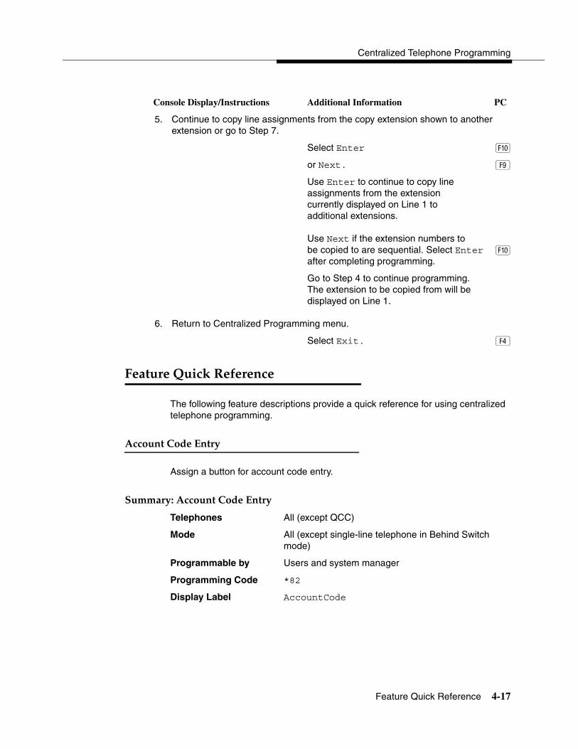
Centralized Telephone Programming
Feature Quick Reference 4-17
Console Display/Instructions Additional Information PC
5. Continue to copy line assignments from the copy extension shown to another extension or go to Step 7.
Select Enter �
or Next. �
Use Enter to continue to copy line assignments from the extension currently displayed on Line 1 to additional extensions.
Use Next if the extension numbers to be copied to are sequential. Select Enter � after completing programming.
Go to Step 4 to continue programming. The extension to be copied from will be displayed on Line 1.
6. Return to Centralized Programming menu.
Select Exit. �
��������#���$�%�&������ 4
The following feature descriptions provide a quick reference for using centralized telephone programming.
����������������! 4
Assign a button for account code entry.
'�����!(�����������������! 4
Telephones All (except QCC)
Mode All (except single-line telephone in Behind Switch mode)
Programmable by Users and system manager
Programming Code *82
Display Label AccountCode

System Programming
4-18 Feature Quick Reference
����� 4
Assign a button to alert the operator to system problems.
'�����!(������ 4
Telephones DLC operator only
Mode All
Programmable by DLC operator and system manager
Programming Code *759
Display Label Alarm
���������������� 4
Assign a button for authorization code entry.
'�����!(����������������� 4
Telephones All (except QCC)
Mode All (except single-line telephone in Behind Switch mode)
Programmable by Users and system manager
Programming Code *80
Display Label Auth Code
��������������� 4
Assign a button to direct calls to an answering device when the user is not available.
'�����!(���������������� 4
Telephones Analog multiline only
Mode All
Programmable by Users and system manager
Programming Code *754
Display Label AutoAns All
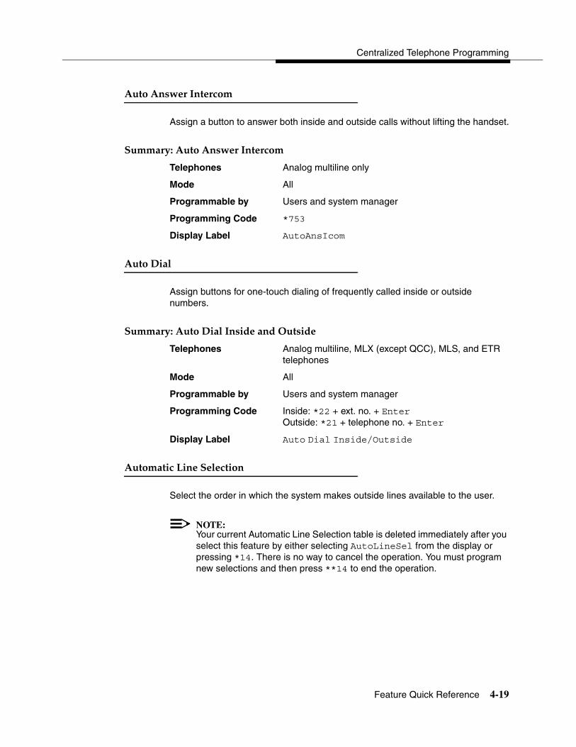
Centralized Telephone Programming
Feature Quick Reference 4-19
�������������������� 4
Assign a button to answer both inside and outside calls without lifting the handset.
'�����!(��������������������� 4
Telephones Analog multiline only
Mode All
Programmable by Users and system manager
Programming Code *753
Display Label AutoAnsIcom
�����)��� 4
Assign buttons for one-touch dialing of frequently called inside or outside numbers.
'�����!(������)������������������� 4
Telephones Analog multiline, MLX (except QCC), MLS, and ETR telephones
Mode All
Programmable by Users and system manager
Programming Code Inside: *22 + ext. no. + EnterOutside: *21 + telephone no. + Enter
Display Label Auto Dial Inside/Outside
���������������'�������� 4
Select the order in which the system makes outside lines available to the user.
NOTE:Your current Automatic Line Selection table is deleted immediately after you select this feature by either selecting AutoLineSel from the display or pressing *14. There is no way to cancel the operation. You must program new selections and then press **14 to end the operation.
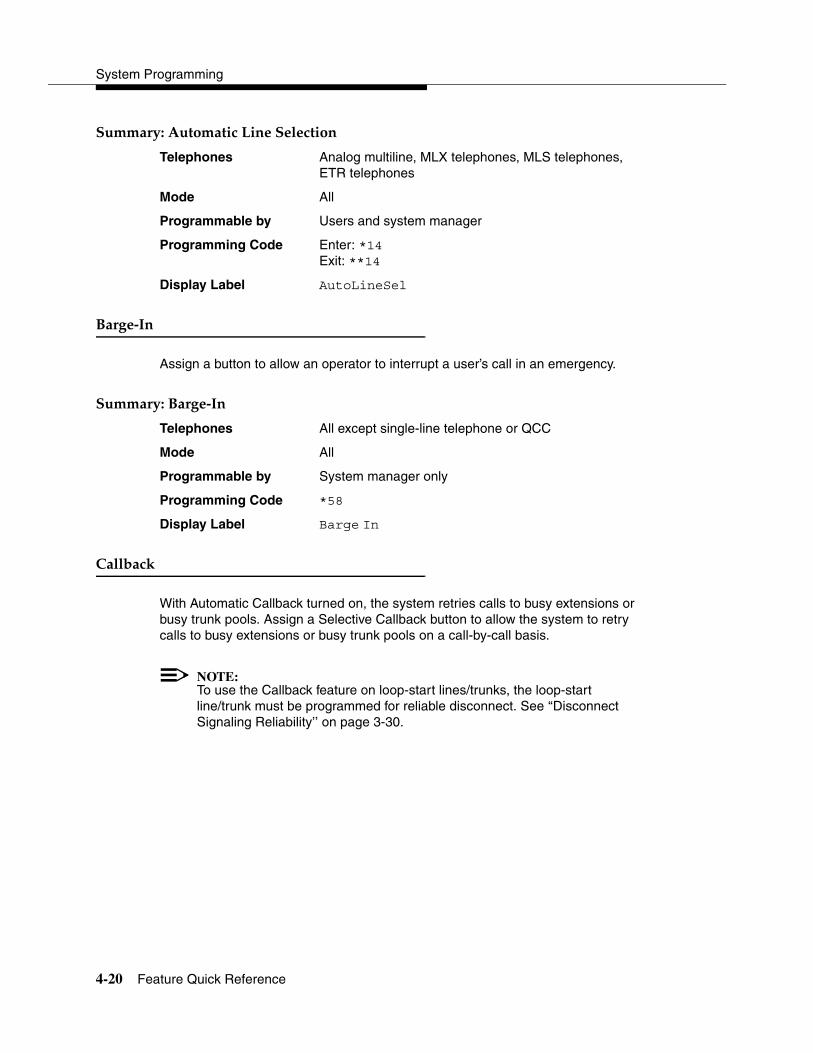
System Programming
4-20 Feature Quick Reference
'�����!(����������������'�������� 4
Telephones Analog multiline, MLX telephones, MLS telephones, ETR telephones
Mode All
Programmable by Users and system manager
Programming Code Enter: *14Exit: **14
Display Label AutoLineSel
"����*�� 4
Assign a button to allow an operator to interrupt a user’s call in an emergency.
'�����!(�"����*�� 4
Telephones All except single-line telephone or QCC
Mode All
Programmable by System manager only
Programming Code *58
Display Label Barge In
����+��$ 4
With Automatic Callback turned on, the system retries calls to busy extensions or busy trunk pools. Assign a Selective Callback button to allow the system to retry calls to busy extensions or busy trunk pools on a call-by-call basis.
NOTE:To use the Callback feature on loop-start lines/trunks, the loop-start line/trunk must be programmed for reliable disconnect. See ‘‘Disconnect Signaling Reliability’’ on page 3-30.
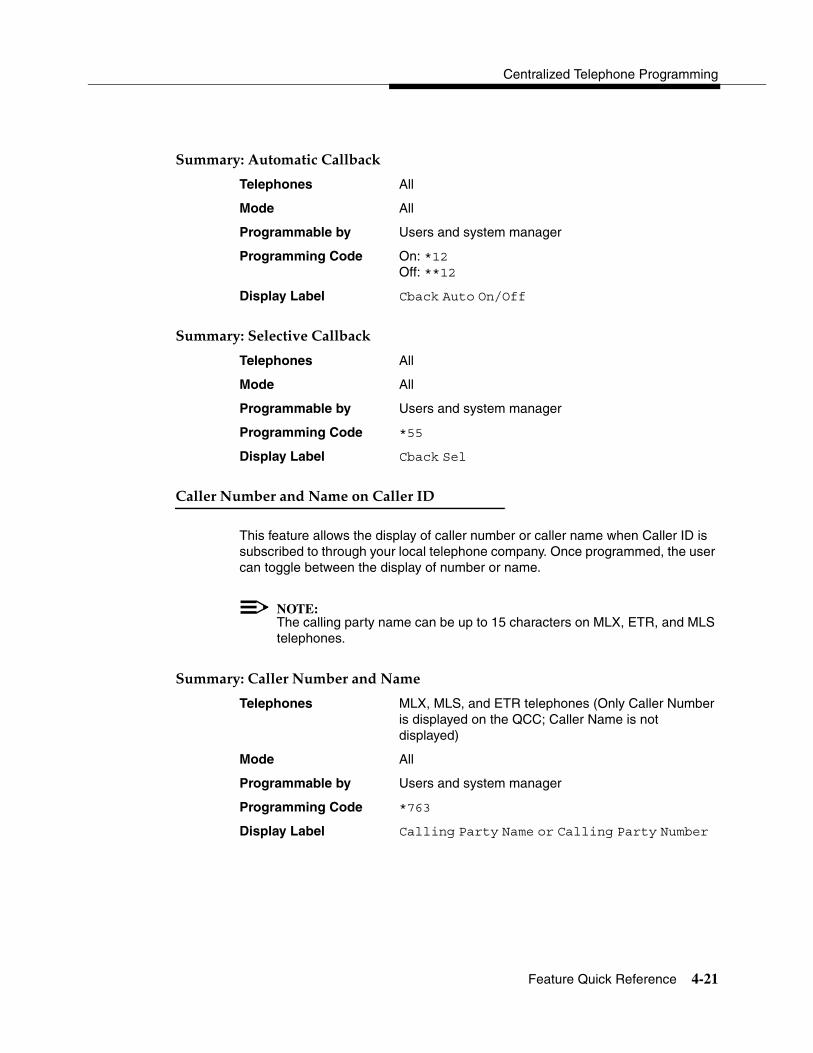
Centralized Telephone Programming
Feature Quick Reference 4-21
'�����!(���������������+��$ 4
Telephones All
Mode All
Programmable by Users and system manager
Programming Code On: *12Off: **12
Display Label Cback Auto On/Off
'�����!(�'�������������+��$ 4
Telephones All
Mode All
Programmable by Users and system manager
Programming Code *55
Display Label Cback Sel
�������,��+������,���������������) 4
This feature allows the display of caller number or caller name when Caller ID is subscribed to through your local telephone company. Once programmed, the user can toggle between the display of number or name.
NOTE:The calling party name can be up to 15 characters on MLX, ETR, and MLS telephones.
'�����!(��������,��+������,��� 4
Telephones MLX, MLS, and ETR telephones (Only Caller Number is displayed on the QCC; Caller Name is not displayed)
Mode All
Programmable by Users and system manager
Programming Code *763
Display Label Calling Party Name or Calling Party Number
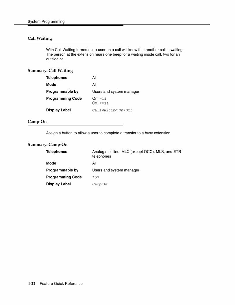
System Programming
4-22 Feature Quick Reference
�����-������ 4
With Call Waiting turned on, a user on a call will know that another call is waiting. The person at the extension hears one beep for a waiting inside call, two for an outside call.
'�����!(������-������ 4
Telephones All
Mode All
Programmable by Users and system manager
Programming Code On: *11Off: **11
Display Label CallWaiting On/Off
��� *�� 4
Assign a button to allow a user to complete a transfer to a busy extension.
'�����!(���� *�� 4
Telephones Analog multiline, MLX (except QCC), MLS, and ETR telephones
Mode All
Programmable by Users and system manager
Programming Code *57
Display Label Camp On
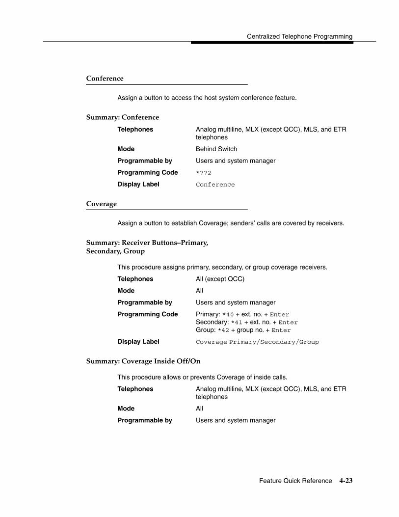
Centralized Telephone Programming
Feature Quick Reference 4-23
���&������ 4
Assign a button to access the host system conference feature.
'�����!(����&������ 4
Telephones Analog multiline, MLX (except QCC), MLS, and ETR telephones
Mode Behind Switch
Programmable by Users and system manager
Programming Code *772
Display Label Conference
�������� 4
Assign a button to establish Coverage; senders’ calls are covered by receivers.
'�����!(�%��������"������.������!/�'������!/ 0��� 4
This procedure assigns primary, secondary, or group coverage receivers.
Telephones All (except QCC)
Mode All
Programmable by Users and system manager
Programming Code Primary: *40 + ext. no. + EnterSecondary: *41 + ext. no. + EnterGroup: *42 + group no. + Enter
Display Label Coverage Primary/Secondary/Group
'�����!(�����������������&&1�� 4
This procedure allows or prevents Coverage of inside calls.
Telephones Analog multiline, MLX (except QCC), MLS, and ETR telephones
Mode All
Programmable by Users and system manager

System Programming
4-24 Feature Quick Reference
Programming Code In/Outside Calls: *48Outside Calls Only: **48
Display Label CoverInside, On/Off
'�����!(�'�����"������/�����������&& 4
This procedure turns off all Coverage.
Telephones Analog multiline, MLX (except QCC), MLS, and ETR telephones
Mode All
Programmable by Users and system manager
Programming Code *49
Display Label Coverage Off
'�����!(����������2 '��&& 4
This procedure prevents outside calls from being sent to voice mail.
Telephones Analog multiline, MLX (except QCC), MLS, and ETR telephones
Mode All
Programmable by Users and system manager
Programming code *46
Display Label Coverage VMS Off
)����'����� 4
Assign a button to indicate when a data call is in progress.
'�����!(�)����'����� 4
Telephones All (except QCC)
Mode All
Programmable by Users and system manager
Programming Code *83 + ext. no. + Enter
Display Label Data Status

Centralized Telephone Programming
Feature Quick Reference 4-25
)������2����� ��� 4
This feature allows one user to call another user’s voice mail, without ringing that user’s telephone.
'�����!(�)������2����� ��� 4
Telephones All
Mode All
Programmable by Users and system manager
Programming Code *56
Display Label Direct VoiceMail
)��,���)�����+ 4
Assign a button to prevent calls from ringing at the telephone.
'�����!(�)��,���)�����+ 4
Telephones Analog multiline, MLX (except QCC), MLS, and ETR telephones
Mode All
Programmable by Users and system manager
Programming Code *47
Display Label DoNotDisturb
)�� 4
Drop is a function that allows a conference participant to eliminate a party from a conference.
'�����!(�)�� 4
Telephones Analog multiline, MLX (except QCC), MLS, and ETR telephones.
In Hybrid/PBX and Key modes, analog multiline and MLX telephones have a fixed Drop button, while MLS and ETR telephones do not. On the MLS and ETR telephones, an ETR Drop button can be programmed with program code *777.

System Programming
4-26 Feature Quick Reference
In Behind Switch mode for analog multiline, MLX, MLS, and ETR telephones, rather than using a fixed drop button, program code *773 must be used to send a drop signal to the MERLIN LEGEND System.
Mode All
Programmable by Users and system manager
Programming Code *773 (for analog multiline, MLX, MLS, and ETR telephones in Behind Switch mode)
*777 (to program ETR Drop for ETR and MLS telephones)
Display Label Drop
����������'����� 4
Assign a button to allow system operators or supervisors to monitor the status of extensions and restrict use of telephones (hotel configuration) or change group members’ availability to take calls (Group Calling/CMS configuration).
'�����!(�)�������������'����� 4
Telephones DLCs
Mode All
Programmable by System manager only
Programming Code Off: *760ES1: *761ES2: *762
Display Label OperatorES, ESOff/ES1/ES2
'�����!(����� ���������������'������3����4 4
Telephones Single-line, analog multiline, MLX, ETR, and MLS telephones
Mode All
Programmable by Users and system manager
Programming Code ES1: *45ES2: *44
Display Label ES Status, ES1/ES2

Centralized Telephone Programming
Feature Quick Reference 4-27
��������"����� 4
Use in conjunction with features that require dial codes.
'�����!(���������"����� 4
Telephones Analog multiline
Mode All
Programmable by Users and system manager
Programming Code *20
Display Label Feature Btn
������ 4
Assign a button to activate the forwarding of a user’s calls to another extension or to an outside number.
'�����!(������� 4
Telephones Single-line, analog multiline, MLX (except QCC), MLS, and ETR telephones
Mode All
Programmable by Users and system manager
Programming Code *33
Display Label Forward
0��� �������� 4
Assign buttons to allow the calling group supervisor or group members to monitor the number of calls in the queue.
'�����!(������*��*#�����������"����� 4
Telephones Analog multiline, MLX, ETR, and MLS telephones
Mode All
Programmable by Users and system manager
Programming Code *22 + calling group ext. no. + Enter
Display Label Group Call
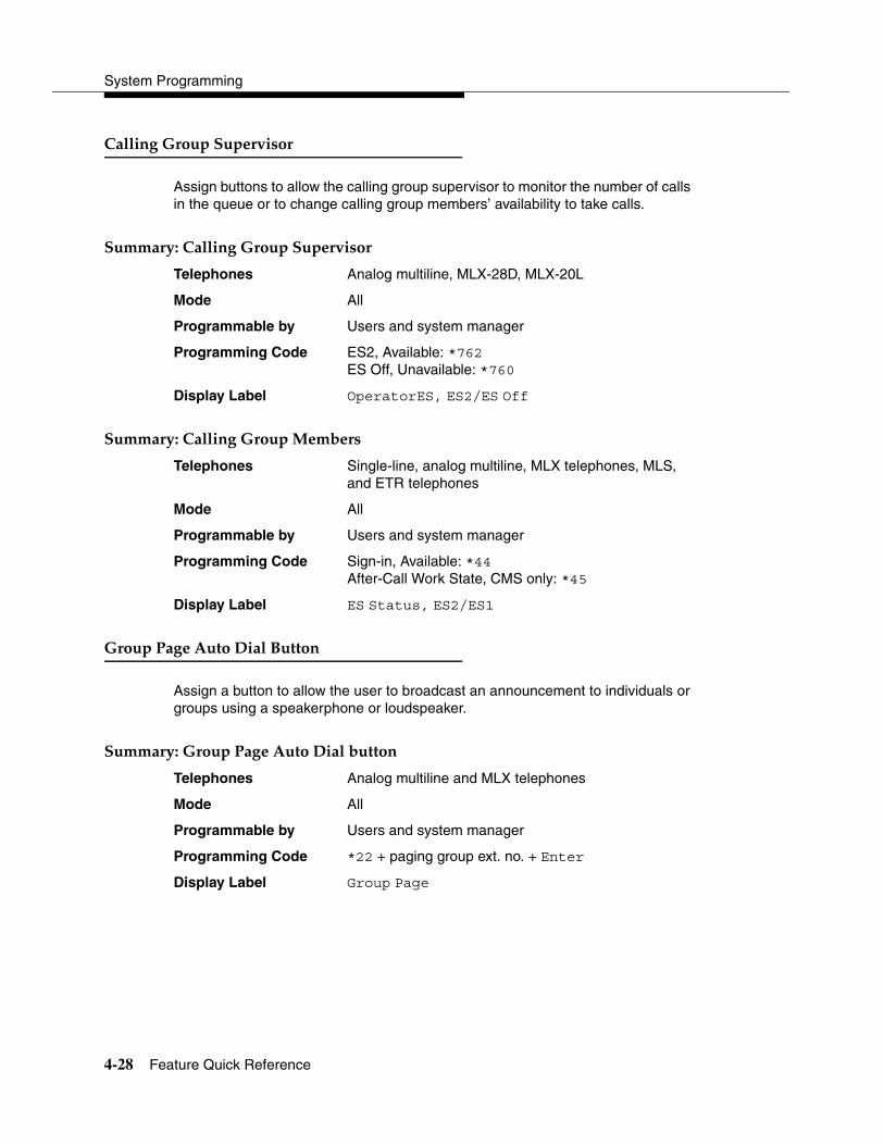
System Programming
4-28 Feature Quick Reference
��������0��� �'� ������� 4
Assign buttons to allow the calling group supervisor to monitor the number of calls in the queue or to change calling group members’ availability to take calls.
'�����!(���������0��� �'� ������� 4
Telephones Analog multiline, MLX-28D, MLX-20L
Mode All
Programmable by Users and system manager
Programming Code ES2, Available: *762ES Off, Unavailable: *760
Display Label OperatorES, ES2/ES Off
'�����!(���������0��� � ��+��� 4
Telephones Single-line, analog multiline, MLX telephones, MLS, and ETR telephones
Mode All
Programmable by Users and system manager
Programming Code Sign-in, Available: *44After-Call Work State, CMS only: *45
Display Label ES Status, ES2/ES1
0��� �����������)����"����� 4
Assign a button to allow the user to broadcast an announcement to individuals or groups using a speakerphone or loudspeaker.
'�����!(�0��� �����������)����+����� 4
Telephones Analog multiline and MLX telephones
Mode All
Programmable by Users and system manager
Programming Code *22 + paging group ext. no. + Enter
Display Label Group Page
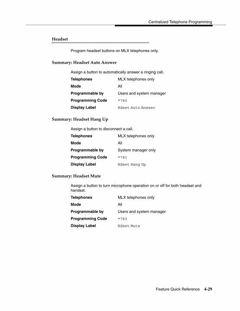
Centralized Telephone Programming
Feature Quick Reference 4-29
5����� 4
Program headset buttons on MLX telephones only.
'�����!(�5����������������� 4
Assign a button to automatically answer a ringing call.
Telephones MLX telephones only
Mode All
Programmable by Users and system manager
Programming Code *780
Display Label Hdset Auto Answer
'�����!(�5������5����� 4
Assign a button to disconnect a call.
Telephones MLX telephones only
Mode All
Programmable by System manager only
Programming Code *781
Display Label Hdset Hang Up
'�����!(�5������ ��� 4
Assign a button to turn microphone operation on or off for both headset and handset.
Telephones MLX telephones only
Mode All
Programmable by Users and system manager
Programming Code *783
Display Label Hdset Mute

System Programming
4-30 Feature Quick Reference
'�����!(�5������'����� 4
Assign a button to activate headset operation.
Telephones MLX telephones only
Mode All
Programmable by Users and system manager
Programming Code *782
Display Label Hdset Status
�����,��+���)��� 4
Assign a button to redial the last number dialed.
'�����!(������,��+���)��� 4
Telephones All
Mode All
Programmable by Users and system manager
Programming Code *84
Display Label LastNumDial
�������� 4
Assign a button to allow users to send, receive, and post messages.
'�����!(������� ��������&����������� 4
Telephones Analog multiline, MLX, MLS, and ETR telephones
Mode All
Programmable by Users and system manager
Programming Code *25
Display Label Leave Msg

Centralized Telephone Programming
Feature Quick Reference 4-31
'�����!(������� ������. ���������)��&& 4
Telephones Analog multiline, MLX, MLS, and ETR telephones
Mode All
Programmable by Users and system manager
Programming Code *54
Display Label none
'�����!(������� ������ 4
Telephones Analog multiline, MLX, MLS, and ETR telephones
Mode All
Programmable by Users and system manager
Programming Code *751
Display Label Posted Msg
'�����!(�'��1%������ ������ 4
Telephones DLC operator only
Mode All
Programmable by Users and system manager
Programming Code *38
Display Label Send/RmvMsg
'�����!(�%��������� �������.)����� 4
Telephones Analog multiline display, MLS, and ETR telephones
Mode All
Programmable by Users and system manager
Programming Code *26
Display Label Messages Delete Msg
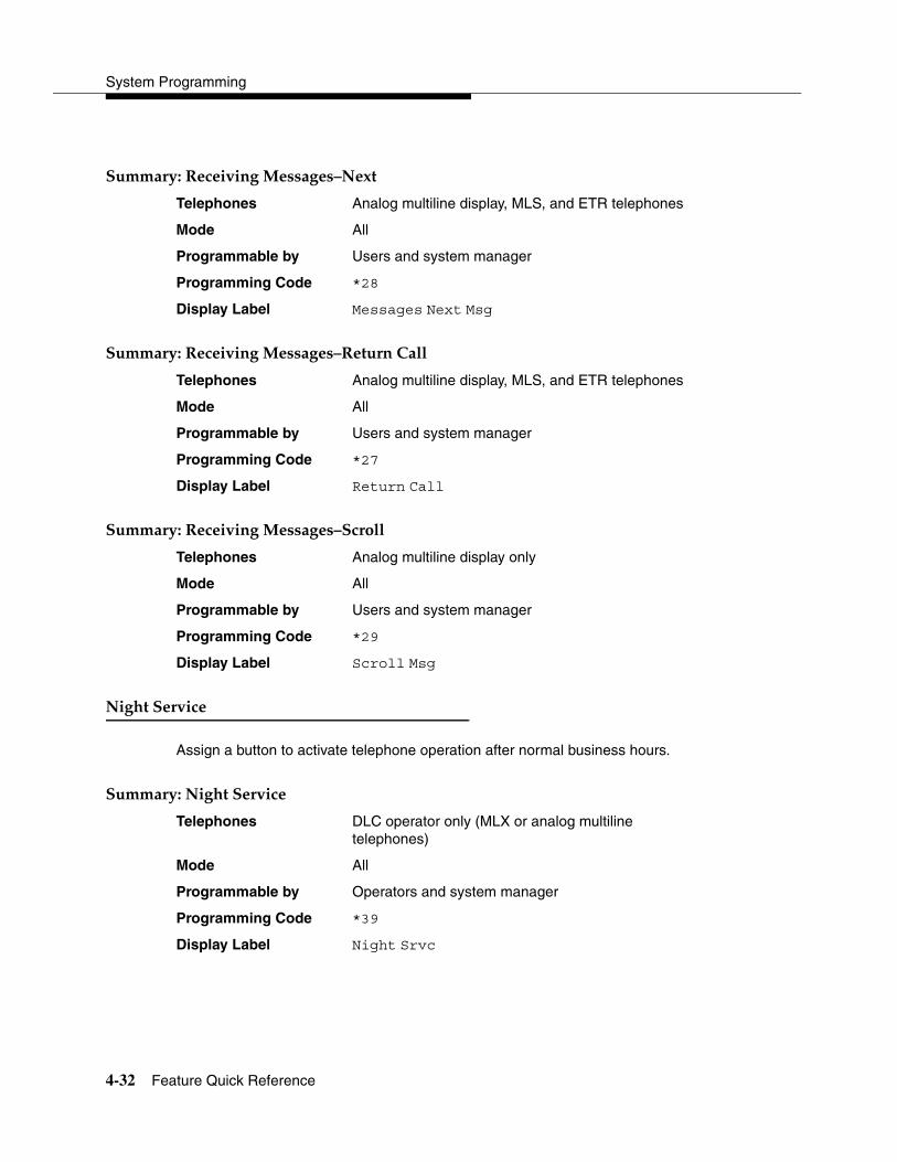
System Programming
4-32 Feature Quick Reference
'�����!(�%��������� �������.,��� 4
Telephones Analog multiline display, MLS, and ETR telephones
Mode All
Programmable by Users and system manager
Programming Code *28
Display Label Messages Next Msg
'�����!(�%��������� �������.%���������� 4
Telephones Analog multiline display, MLS, and ETR telephones
Mode All
Programmable by Users and system manager
Programming Code *27
Display Label Return Call
'�����!(�%��������� �������.'����� 4
Telephones Analog multiline display only
Mode All
Programmable by Users and system manager
Programming Code *29
Display Label Scroll Msg
,�����'������ 4
Assign a button to activate telephone operation after normal business hours.
'�����!(�,�����'������ 4
Telephones DLC operator only (MLX or analog multiline telephones)
Mode All
Programmable by Operators and system manager
Programming Code *39
Display Label Night Srvc

Centralized Telephone Programming
Feature Quick Reference 4-33
,���&! 4
Assign buttons to allow users to send a visual signal to another extension without making a call to that extension.
'�����!(�,���&!.'������%������ 4
Telephones Analog multiline, MLX, MLS, and ETR telephones
Mode All
Programmable by Users and system manager
Programming Code Send: *757 + ext. no. + EnterReceive: *758 + ext. no. + Enter
Display Label Notify Send/Receive
���$ 4
Assign a button to hold a call and allow the call to be picked up at any telephone in the system.
'�����!(����$ 4
Telephones All (except single-line telephones in Behind Switch mode)
Mode All
Programmable by Users and system manager
Programming Code *86
Display Label Park

System Programming
4-34 Feature Quick Reference
���$�6���������)��� 4
Assign a button to allow DLC operators to hold a call at a specified extension or park zone.
'�����!(����$�6���������)��� 4
Telephones DLC operator only
Mode All
Programmable by Users and system manager
Programming Code *22 + Park Zone + Enter
Display Label Park Zone
���������' ���)��� 4
Use this procedure to program codes that allow users to dial outside numbers by dialing a 2-digit code.
'�����!(����������' ���)��� 4
Telephones Single-line, analog multiline, and telephones with 10 or fewer buttons
Mode All
Programmable by Users and system manager
Programming Code # + 2-digit code (01–24) + *21 + tel. no. + # + Enter
Display Label PerSpeedD1
���$� 4
Assign buttons to allow users to answer calls that are ringing, parked, or on hold anywhere in the system.
'�����!(����$� .0����������/' ���&�� ���������/�' ���&������� 4
Telephones All
Mode All
Programmable by Users and system manager
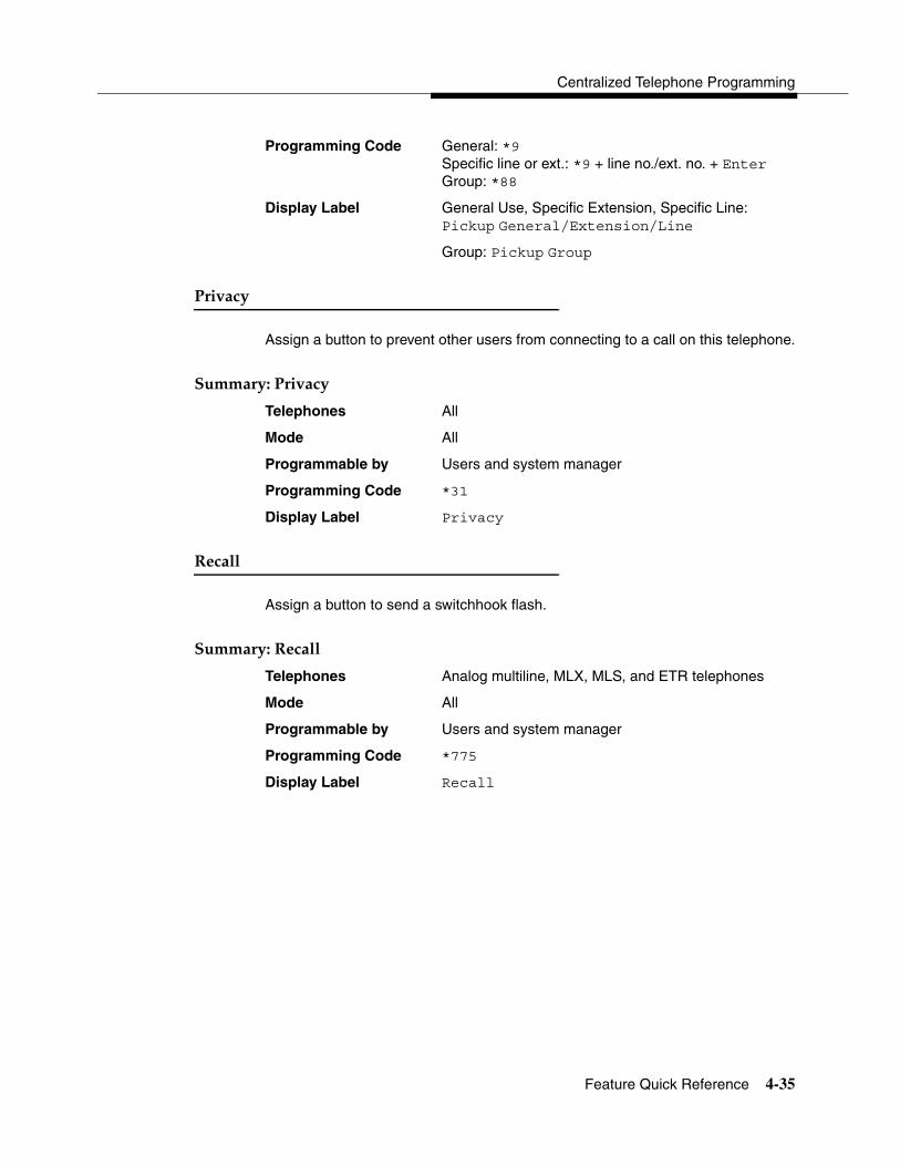
Centralized Telephone Programming
Feature Quick Reference 4-35
Programming Code General: *9Specific line or ext.: *9 + line no./ext. no. + Enter Group: *88
Display Label General Use, Specific Extension, Specific Line:Pickup General/Extension/Line
Group: Pickup Group
������! 4
Assign a button to prevent other users from connecting to a call on this telephone.
'�����!(�������! 4
Telephones All
Mode All
Programmable by Users and system manager
Programming Code *31
Display Label Privacy
%����� 4
Assign a button to send a switchhook flash.
'�����!(�%����� 4
Telephones Analog multiline, MLX, MLS, and ETR telephones
Mode All
Programmable by Users and system manager
Programming Code *775
Display Label Recall

System Programming
4-36 Feature Quick Reference
%�������'������ 4
Assign buttons to allow the system to make calls automatically at preset times and cancel reminder service calls and operator reminder calls that were not answered.
'�����!(�'��/�������/���� ���� %������ '������ 4
Telephones All
Mode All
Programmable by Users and system manager
Programming Code Set: *81Cancel: **81Missed: *752
Display Label Reminder Set/Cancel/Missed
%������1������������&������ 4
Use this procedure to turn on Ringing/Idle Line Preference.
'�����!(�%����������������������&������ 4
Telephones Analog multiline, MLX, MLS, and ETR telephones
Mode All
Programmable by Users and system manager
Programming Code On: *343Off: *344
Display Label Line Prefer, On/Off

Centralized Telephone Programming
Feature Quick Reference 4-37
%�������� ����� 4
'�����!(������������%������ 4
Use this procedure to individualize the telephone ring.
Telephones Analog multiline, MLX, MLS, and ETR telephones
Mode All
Programmable by Users and system manager
Programming Code *32 + ring pattern (1–8)
Display Label Personal Ring Pattern #n
'�����!(�%������������ ����� 4
Use this procedure to establish whether and how individual lines, or all lines, ring at a telephone.
Telephones Analog multiline, MLX, MLS, and ETR telephones
Mode All
Programmable by Users and system manager
Programming Code Individual Lines:Immediate: *37Delay: *36No Ring: *35
All Lines:Immediate: *347Delay: *346No Ring: *345
Display Label Individual Lines:Ring Options One Line Immed/Delay/No Ring
All Lines:Ring Options All Lines Immed/Delay/No Ring
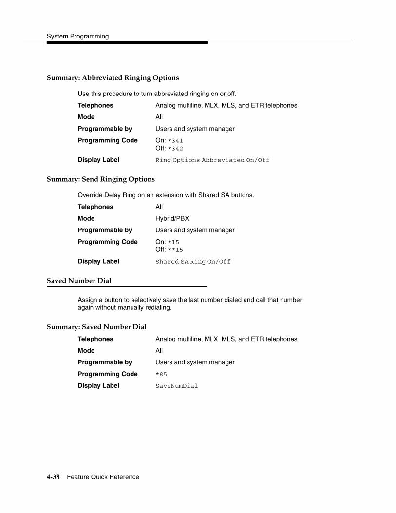
System Programming
4-38 Feature Quick Reference
'�����!(��++��������%�������� ����� 4
Use this procedure to turn abbreviated ringing on or off.
Telephones Analog multiline, MLX, MLS, and ETR telephones
Mode All
Programmable by Users and system manager
Programming Code On: *341Off: *342
Display Label Ring Options Abbreviated On/Off
'�����!(�'���%�������� ����� 4
Override Delay Ring on an extension with Shared SA buttons.
Telephones All
Mode Hybrid/PBX
Programmable by Users and system manager
Programming Code On: *15Off: **15
Display Label Shared SA Ring On/Off
'����,��+���)��� 4
Assign a button to selectively save the last number dialed and call that number again without manually redialing.
'�����!(�'����,��+���)��� 4
Telephones Analog multiline, MLX, MLS, and ETR telephones
Mode All
Programmable by Users and system manager
Programming Code *85
Display Label SaveNumDial
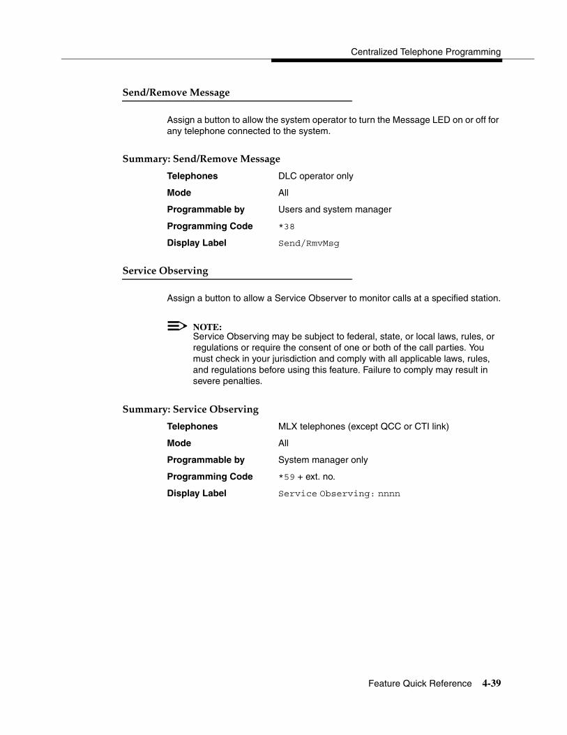
Centralized Telephone Programming
Feature Quick Reference 4-39
'��1%������ ������ 4
Assign a button to allow the system operator to turn the Message LED on or off for any telephone connected to the system.
'�����!(�'��1%������ ������ 4
Telephones DLC operator only
Mode All
Programmable by Users and system manager
Programming Code *38
Display Label Send/RmvMsg
'��������+������� 4
Assign a button to allow a Service Observer to monitor calls at a specified station.
NOTE:Service Observing may be subject to federal, state, or local laws, rules, or regulations or require the consent of one or both of the call parties. You must check in your jurisdiction and comply with all applicable laws, rules, and regulations before using this feature. Failure to comply may result in severe penalties.
'�����!(�'��������+������� 4
Telephones MLX telephones (except QCC or CTI link)
Mode All
Programmable by System manager only
Programming Code *59 + ext. no.
Display Label Service Observing: nnnn
System Programming
4-40 Feature Quick Reference
'�������� 4
Assign a button to allow a user to send an audible signal to another extension without making a call to that extension.
'�����!(�'���������7������8 4
Telephones Analog multiline, MLX, MLS, and ETR telephones
Mode All
Programmable by Users and system manager
Programming Code *23 + ext. no. + Enter
Display Label Signal
'!�����������1���������"������ 4
Assign Intercom or System Access buttons on telephones.
'�����!(��������'!�����������1���������"������ 4
Telephones All
Mode Intercom buttonsKey, Behind Switch
System Access buttonsHybrid/PBX
Programmable by System manager only
Programming Code Intercom buttons:Assign Intercom Ring button: *16Assign Intercom Originate Only button: *18
System Access buttons:Assign Ring button: *16Assign Originate Only button: *18
Display Label SysAccess/SysAcc-00

Centralized Telephone Programming
Feature Quick Reference 4-41
'�����!(��������'�����'!������������"������ 4
Telephones All
Mode Hybrid/PBX
Programmable by System manager only
Programming Code *17 + primary ext. no.
Display Label ShareSysAcc
'�����!(���������! ���&�'!������������"����� 4
Telephones All
Mode Intercom buttons:Key, Behind Switch
System Access buttons:Hybrid/PBX
Programmable by Users and system manager
Programming Code Ring: **19Voice: *19
Display Label Voice Annce, Place Ring/Voice
'!�����' ���)��� 4
Assign a button to dial any 3-digit speed dial code.
'�����!(�'!�����' ���)��� 4
Telephones All
Mode All
Programmable by Users and system manager
Programming Code *24 + 3-digit code (600–729) + Enter
Display Label SysSpeedDl

System Programming
4-42 Feature Quick Reference
�����&�� 4
Assign a button to access the host system Transfer feature.
'�����!(������&�� 4
Telephones Analog multiline, MLX, MLS, and ETR telephones
Mode Behind Switch
Programmable by Users and system manager
Programming Code *774
Display Label Transfer
2������������� 4
Allows users to prevent inside calls on their speakerphone, receive inside calls on their speakerphone whether they are busy on a call or not, or —for MLX telephone users only—receive inside calls on their speakerphone only when their telephone is idle and they are not busy on a call.
'�����!(�2������������� 4
Telephones Analog multiline, MLX, MLS, and ETR telephones
Mode All
Programmable by Users and system manager
Programming Code On: *10Off: **10 VA on Idle Only: *130 (MLX telephones only)
Display Label Voice Annce Receive On/Off/VA on Idle Only

Support Telephone Number A-1
A��������������� �������� A
������������� ������� 4
In the USA only, Lucent Technologies provides a toll-tree customer Helpline (1-800-628-2888) 24 hours a day. If you need assistance when installing, programming, or using your system, call the Helpline or your Lucent Technologies representative. Consultation charges may apply.
Outside the USA, if you need assistance when installing, programming, or using your system, contact your Lucent Technologies representative.
������������ ������ ���������� ��������������� ����� ������� ��� �������� 4
This equipment has been tested and found to comply with the limits for a Class A digital device, pursuant to Part 15 of the FCC Rules. These limits are designed to provide reasonable protection against harmful interference when the equipment is operated in a commercial environment. This equipment generates, uses, and can radiate radio frequency energy and, if not installed and used in accordance with the instruction manual, may cause harmful interference to radio communications. Operation of this equipment in a residential area is likely to cause harmful interference, in which case the user will be required to correct the interference at his or her own expense.

System Programming
A-2 Canadian Department of Communications (DOC) Interference Information
�� ���� �������� �������� ������ ������� ������� ��� �������� 4
This digital apparatus does not exceed the Class A limits for radio noise emissions set out in the radio interference regulations of the Canadian Department of Communications.
Le Présent Appareil Numérique n’émet pas de bruits radioélectriques dépassant les limites applicables aux appareils numériques de la classe A préscrites dans le règlement sur le brouillage radioélectrique edicté par le ministère des Communications du Canada.
�������������� � �������� �������� 4
This equipment is registered with the FCC in accordance with Part 68 of its rules. In compliance with those rules, you are advised of the following:
� Means of Connection. Connection of this equipment to the telephone network shall be through a standard network interface jack, USOC RJ11C, RJ14C, or RJ21X. Connection to E&M tie trunks requires a USOC RJ2GX. Connection to off-premises extensions requires a USOC RJ11C or RJ14C. Connection to 1.544-Mbps digital facilities must be through a USOC RJ48C or RJ48X. Connection to DID requires a USOC RJ11C, RJ14C, or RJ21X. These USOCs must be ordered from your telephone company. Connection to 56-Kbps or 64-Kbps facilities requires a USOC RJ11C, RJ14C, or RJ21.
� Party Lines and Coin Telephones. This equipment may not be used with party lines or coin telephone lines.
� Notification to the Telephone Companies. Before connecting this equipment, you or your equipment supplier must notify your local telephone company’s business office of the following:
— The telephone number or numbers you will be using with this equipment.
� The appropriate registration number and ringer equivalence number (REN), which can be found on the back or bottom of the control unit, as follows:
� If this equipment is to be used as a Key system, report the number AS593M-72914-KF-E.
� If the system provides both manual and automatic selection of incoming/outgoing access to the network, report the number AS593M-72682-MF-E.
Customer Support Information
FCC Notification and Repair Information A-3
� If there are no directly terminated trunks, or if the only directly terminated facilities are personal lines, report the number AS5USA-65646-PF-E.
� The REN (Ringer Equivalence Number) for all three systems is 1.5A.
— The facility interface code (FIC) and service order code (SOC): For tie line connection, the FIC is TL31M and the SOC is 9.0F.
� For connection to off-premises stations, the FIC is OL13C and the SOC is 9.0F.
� For equipment to be connected to DID facilities, the FIC is 02RV2-T and the SOC is AS.2.
� For equipment to be connected to 1.544-Mbps digital service, the SOC is 6.0P and the FIC is:
— 04DU9-BN for D4 framing format with AMI zero code suppression.
— 04DU9-DN for D4 framing format with bipolar 8 zero code suppression (B8ZS).04DU9-IKN for extended superframe format (ESF) with AMI zero code suppression.
— 04DU9-ISN with ESF and B8ZS.
� For equipment to be connected to 56-Kbps or 64-Kbps digital facilities, the FIC is 02B1Q.
— The quantities and USOC numbers of the jacks required.
— For each jack, the sequence in which lines are to be connected, the line types, the FIC, and the REN by position, when applicable.
� Ringer Equivalence Number (REN). The REN is used to determine the number of devices that may be connected to the telephone line. Excessive RENs on the line may result in the devices not ringing in response to an incoming call. In most, but not all, areas, the sum of the RENs should not exceed five (5.0). To be certain of the number of devices that may be connected to the line, as determined by the total RENs, contact the local telephone company to determine the maximum REN for the calling area.
� Disconnection. You must also notify your local telephone company if and when this equipment is permanently disconnected from the line or lines.

System Programming
A-4 Installation and Operational Procedures
� ��������� � ��������� �� ��������� 4
The guides for your system contain information about installation and operational procedures.
� Repair Instructions. If you experience trouble because your equipment is malfunctioning, the FCC requires that the equipment not be used and that it be disconnected from the network until the problem has been corrected. Repairs to this equipment can be made only by the manufacturers, their authorized agents, or others who may be authorized by the FCC. In the event repairs are needed on this equipment, contact your authorized Lucent Technologies dealer or, in the USA only, contact the National Service Assistance Center (NSAC) at 1-800-628-2888.
� Rights of the Local Telephone Company. If this equipment causes harm to the telephone network, the local telephone company may discontinue your service temporarily. If possible, they will notify you in advance. But if advance notice is not practical, you will be notified as soon as possible. You will also be informed of your right to file a complaint with the FCC.
� Changes at Local Telephone Company. Your local telephone company may make changes in its facilities, equipment, operations, or procedures that affect the proper functioning of this equipment. If they do, you will be notified in advance to give you an opportunity to maintain uninterrupted telephone service.
� Hearing Aid Compatibility. The custom telephone sets for this system are compatible with inductively coupled hearing aids as prescribed by the FCC.
� Automatic Dialers. WHEN PROGRAMMING EMERGENCY NUMBERS AND/OR MAKING TEST CALLS TO EMERGENCY NUMBERS:
— Remain on the line and briefly explain to the dispatcher the reason for the call.
— Perform such activities in off-peak hours, such as early morning or late evening.
� Direct Inward Dialing (DID). This equipment returns answer supervision signals to the Public Switched Telephone Network when:
— Answered by the called station.
— Answered by the attendant.
— Routed to a recorded announcement that can be administered by the customer premises equipment user.
— Routed to a dial prompt.

Customer Support Information
DOC Notification and Repair Information A-5
This equipment returns answer supervision on all DID calls forwarded back to the Public Switched Telephone Network. Permissible exceptions are when:
— A call is unanswered.
— A busy tone is received.
— A reorder tone is received.
Allowing this equipment to be operated in such a manner as not to provide proper answer supervision signaling is in violation of Part 68 rules.
New Network Area and Exchange Codes. The MERLIN LEGEND Communications System software does not restrict access to any new area codes or exchange codes established by a local telephone company. If the user has established toll restrictions on the system that could restrict access, then the user should check the lists of allowed and disallowed dial codes and modify them as needed.
Equal Access Codes. This equipment is capable of providing users access to interstate providers of operator services through the use of access codes. Modifications of this equipment by call aggregators to block access dialing codes is a violation of the Telephone Operator Consumers Act of 1990.
�������������� � �������� �������� 4
NOTICE: The Canadian Department of Communications (DOC) label identifies certified equipment. This certification means that the equipment meets certain protective, operational, and safety requirements of the telecommunications network. The DOC does not guarantee the equipment will operate to the user’s satisfaction.
Before installing this equipment, users should ensure that it is permissible to connect it to the facilities of the local telecommunications company. The equipment must also be installed using an acceptable method of connection. In some cases, the company’s inside wiring for single-line individual service may be extended by means of a certified connector assembly (telephone extension cord). The customer should be aware that compliance with the above conditions may not prevent degradation of service in some situations.
Repairs to certified equipment should be made by an authorized Canadian maintenance facility designated by the supplier. Any repairs or alterations made by the user to this equipment, or any equipment malfunctions, may give the telecommunications company cause to request the user to disconnect the equipment.
System Programming
A-6 Renseignements sur la Notification du Ministère des Communications du Canada et la
Users should ensure, for their own protection, that the electrical ground connections of the power utility, telephone lines, and internal metallic water pipe system, if present, are connected. This precaution may be particularly important in rural areas.
! CAUTION:Users should not attempt to make such connections themselves, but should contact the appropriate electrical inspection authority or electrician.
To prevent overloading, the Load Number (LN) assigned to each terminal device denotes the percentage of the total load to be connected to a telephone loop used by the device. The termination on a loop may consist of any combination of devices subject only to the requirement that the total of the Load Numbers of all the devices does not exceed 100.
DOC Certification No.: 230 4095ACSA Certification No.: LR 56260Load No.: 6
�� ���� ��� ������������������ ��!� ���"���������� ������ ����� ��������#������� 4
AVIS: L’étiquette du ministère des Communications du Canada identifie le matériel homologué. Cette étiquette certifie que le matériel est conforme à certaines normes de protection, d’exploitation et de sécurité des réseaux de télécommunications. Le Ministère n’assure toutefois pas que le matériel fonctionnera à la satisfaction de l’utilisateur.
Avant d’installer ce matériel, l’utilisateur doit s’assurer qu’il est permis de le raccorder aux installations de l’entreprise locale de télécommunication. Le matériel doit également être installé en suivant une méthode acceptée de raccordement. Dans certains cas, les fils intérieurs de l’enterprise utilisés pour un service individuel à ligne unique peuvent être prolongés au moyen d’un dispositif homologué de raccordement (cordon prolongateur téléphonique interne). L’abonné ne doit pas oublier qu’il est possible que la conformité aux conditions énoncées ci-dessus n’empêchent pas la dégradation du service dans certaines situations. Actuellement, les entreprises de télécommunication ne permettent pas que l’on raccorde leur matériel à des jacks d’abonné, sauf dans les cas précis prévus pas les tarifs particuliers de ces entreprises.
Les réparations de matériel homologué doivent être effectuées par un centre d’entretien canadien autorisé désigné par le fournisseur. La compagnie de télécommunications peut demander à l’utilisateur de débrancher un appareil à la

Customer Support Information
Renseignements sur la Notification du Ministère des Communications du Canada et la
suite de réparations ou de modifications effectuées par l’utilisateur ou à cause de mauvais fonctionnement.
Pour sa propre protection, l’utilisateur doit s’assurer que tous les fils de mise à la terre de la source d’énergie électrique, des lignes téléphoniques et des canalisations d’eau métalliques, s’il y en a, sont raccordés ensemble. Cette précaution est particuliérement importante dans les régions rurales.
AVERTISSEMENT: L’utilisateur ne doit pas tenter de faire ces raccordements lui-même; il doit avoir recours à un service d’inspection des installations électriques, ou à un électricien, selon le cas.
L’indice de charge (IC) assigné à chaque dispositif terminal indique, pour éviter toute surcharge, le pourcentage de la charge totale qui peut être raccordée à un circuit téléphonique bouclé utilisé par ce dispositif. La terminaison du circuit bouclé peut être constituée de n’importe quelle combinaison de dispositifs, pourvu que la somme des indices de charge de l’ensemble des dispositifs ne dépasse pas 100.
No d’homologation: 230 4095ANo de certification: CSA LR 56260L’indice de charge: 6
A-7
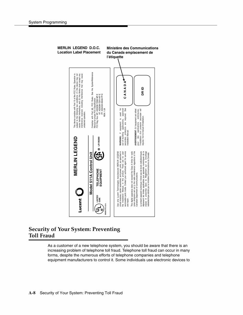
System Programming
A-8 Security of Your System: Preventing Toll Fraud
������$��%���$����& ��'� �� ���������� 4
As a customer of a new telephone system, you should be aware that there is an increasing problem of telephone toll fraud. Telephone toll fraud can occur in many forms, despite the numerous efforts of telephone companies and telephone equipment manufacturers to control it. Some individuals use electronic devices to
ME
RL
IN L
EG
EN
D
Mo
del
511
A C
on
tro
l Un
it
UL
®M
AD
E IN
U.S
.A.
LIS
TE
D53
8ET
EL
EP
HO
NE
EQ
UIP
ME
NT
®L
R56
260
C A
N A
D A
DR
ID
MERLIN LEGEND D.O.C.Location Label Placement
Ministère des Communicationsdu Canada emplacement del’étiquette
This
dev
ice
com
plie
s w
ith P
art 1
5 of
the
FCC
Rul
es. O
pera
tion
is
subj
ect
to t
he f
ollo
win
g tw
o co
nditi
ons:
(1)
thi
s de
vice
may
not
ca
use
harm
ful
inte
rfere
nce,
and
(2)
thi
s de
vice
mus
t ac
cept
any
in
terfe
renc
e re
ceiv
ed,
incl
udin
g in
terfe
renc
e th
at
may
ca
use
unde
sire
d op
erat
ion.
Com
plie
s w
ith P
art
68,
FCC
Rul
es.
See
the
Sys
tem
Ref
eren
ce
Man
ual f
or p
rope
r FC
C C
lass
ifica
tion.
FCC
Reg
. Nos
. MF:
AS5
93M
-726
82-M
F-E
KF:
AS5
93M
-729
14-K
F-E
PF:
AS5
USA
-656
46-P
F-E
REN
: 1.5
A
Use
onl
y Lu
cent
Tec
hnol
ogie
s m
anuf
actu
red
ME
RLI
N L
EG
EN
D
circ
uit m
odul
es, c
arrie
r as
sem
blie
s, a
nd p
ower
uni
ts, a
s sp
ecifi
ed in
th
e In
stal
latio
n M
anua
l, in
th
is
prod
uct.
Ther
e ar
e no
us
er
serv
icea
ble
parts
insi
de.
Con
tact
you
r au
thor
ized
age
nt f
or s
ervi
ce
and
repa
ir.
This
dig
ital a
ppar
atus
doe
s no
t ex
ceed
the
Cla
ss A
lim
its f
or r
adio
no
ise
emis
sion
s se
t ou
t in
the
rad
io in
terfe
renc
e re
guat
ions
of
the
Can
adia
n D
epar
tmen
t of C
omm
unic
atio
ns.
Le p
rése
nt a
ppar
eil n
umér
ique
n’é
met
pas
de
brui
ts ra
dioé
lect
rique
s dé
pass
ant
les
limite
s ap
plic
able
s au
x ap
pare
ils n
umér
ique
s de
la
clas
se
A
pres
crite
s da
ns
le
Règ
lem
ent
sur
le
brou
illag
e ra
dioé
lect
rique
édi
cté
par l
e m
inis
tère
Com
mun
icat
ions
du
Can
ada.
WA
RN
ING
: If
equi
pmen
t is
us
ed
for
out–
of–b
uild
ing
appl
icat
ions
, ap
prov
ed
seco
ndar
y pr
otec
tors
ar
e re
quire
d.
See
In
stal
latio
n M
anua
l.
AVE
RTI
SSEM
ENT:
Si l
’equ
ipm
ent e
st u
tilis
é po
ur
des
appl
icat
ions
ex
térie
ures
, l’i
nsta
llatio
n d’
un
prot
ecto
r se
cond
air
est
requ
ise.
Voi
r le
man
uel d
’Inst
alla
tion.

Customer Support Information
Security of Your System: Preventing Toll Fraud A-9
prevent or falsify records of these calls. Others charge calls to someone else’s number by illegally using lost or stolen calling cards, billing innocent parties, clipping on to someone else’s line, and breaking into someone else’s telephone equipment physically or electronically. In certain instances, unauthorized individuals make connections to the telephone network through the use of the Remote Access features of your system.
The Remote Access features of your system, if you choose to use them, permit off-premises callers to access the system from a remote telephone by using a telephone number with or without a barrier code. The system returns an acknowledgment, signaling the user to key in his or her barrier code, which is selected and administered by the system manager. After the barrier code is accepted, the system returns dial tone to the user. In Release 3.1 and later systems, barrier codes are, by default, restricted from making outside calls. In prior releases, if you do not program specific outward calling restrictions, the user is able to place any call normally dialed from a telephone associated with the system. Such an off-premises network call is originated at, and will be billed from, the system location.
The Remote Access feature, as designed, helps the customer, through proper administration, to minimize the ability of unauthorized persons to gain access to the network. Most commonly, telephone numbers and codes are compromised when overheard in a public location, through theft of a wallet or purse containing access information, or through carelessness (for example, writing codes on a piece of paper and improperly discarding it). Additionally, hackers may use a computer to dial an access code and then publish the information to other hackers. Enormous charges can be run up quickly. It is the customer’s responsibility to take the appropriate steps to properly implement the features, evaluate and administer the various restriction levels, protect access codes, and distribute access codes only to individuals who have been fully advised of the sensitive nature of the access information.
Common carriers are required by law to collect their tariffed charges. While these charges are fraudulent charges made by persons with criminal intent, applicable tariffs state that the customer of record is responsible for payment of all long-distance or other network charges. Lucent Technologies cannot be responsible for such charges and will not make any allowance or give any credit for charges that result from unauthorized access.
To minimize the risk of unauthorized access to your communications system:
� Use an unpublished Remote Access number.
� Assign access codes randomly to users on a need-to-have basis, keeping a log of all authorized users and assigning one code to each person.
� Use random-sequence access codes, which are less likely to be broken.
� Use the longest-length access codes the system will allow.

System Programming
A-10 Toll Fraud Prevention
� Deactivate all unassigned codes promptly.
� Ensure that Remote Access users are aware of their responsibility to keep the telephone number and any access codes secure.
� When possible, restrict the off-network capability of off-premises callers, using calling restrictions, Facility Restriction Levels (Hybrid/PBX mode only), and Disallowed List capabilities. In Release 3.1 and later systems, a prepared Disallowed List (number 7) is provided and is designed to prevent the types of calls that toll-fraud abusers often make.
� When possible, block out-of-hours calling.
� Frequently monitor system call detail reports for quicker detection of any unauthorized or abnormal calling patterns.
� Limit Remote Call Forwarding to persons on a need-to-have basis.
� Change access codes every 90 days.
� Use the longest-length barrier codes possible, following the guidelines for passwords. (See ‘‘Choosing Passwords’’ on page A-19.)
��������� ��'� ��� 4
Toll fraud is the unauthorized use of your telecommunications system by third parties to make long-distance telephone calls. Under the law, you, the customer, are responsible for paying part or all of those unauthorized calls. Thus, the following information is of critical importance.
Unauthorized persons concentrate their activities in two areas with the MERLIN LEGEND Communications System:
� They try to transfer out of the MERLIN LEGEND Communications System to gain access to an outgoing trunk and make long-distance calls.
� They try to locate unused or unprotected mailboxes and use them as drop-off points for their own messages.
The following is a discussion of how toll fraud is often perpetrated and ways to prevent unauthorized access that can lead to toll fraud.
�$�����������$(������ �� ���� �(� �)� ����������$!������� 4
Criminals called hackers may attempt to gain unauthorized access to your communications system and voice messaging system in order to use the system features. Hackers often attempt to trick employees into providing them with access to a network facility (line/trunk) or a network operator. This is referred to as social engineering. Hackers may pose as telephone company employees or employees

Customer Support Information
Toll Fraud Prevention A-11
of Lucent Technologies or your authorized dealer. Hackers will go through a company’s trash to find directories, dialing instructions, and other information that will enable them to break into the system. The more knowledgeable they appear to be about the employee names, departments, telephone numbers, and the internal procedures of your company, the more likely it is that they will be able to trick an employee into helping them.
��'� ��'�!������� 4
Take the following preventive measures to limit the risk of unauthorized access by hackers:
� Provide good physical security for the room containing your telecommunications equipment and the room with administrative tools, records, and system manager information. These areas should be locked when not attended.
� Provide a secure trash disposal for all sensitive information, including telephone directories, call accounting records, or anything that may supply information about your communications system. This trash should be shredded.
� Educate employees that hackers may try to trick them into providing them with dial tone or dialing a number for them. All reports of trouble, requests for moving extensions, or any other administrative details associated with the MERLIN LEGEND Communications System should be handled by one person (the system manager) or within a specified department. Anyone claiming to be a telephone company representative should be referred to this person or department.
� No one outside of Lucent Technologies needs to use the MERLIN LEGEND Communications System to test facilities (lines/trunks). If a caller claims to be a Lucent Technologies employee, the system manager should ask for a telephone number where the caller can be reached. The system manager should be able to recognize the number as a Lucent Technologies telephone number. Before connecting the caller to the administrative port of the MERLIN LEGEND Communications System, the system manager should feel comfortable that a good reason to do so exists. In any event, it is not advisable to give anyone access to network facilities or operators, or to dial a number at the request of the caller.
� Any time a call appears to be suspicious, call the Lucent Technologies BCS Fraud Intervention Center at 1-800-628-2888 (fraud intervention for System 25, PARTNER®
and MERLIN Systems).
� Customers should also take advantage of Lucent Technologies monitoring services and devices, such as the NetPROTECTSM family of fraud-detection services, CAS with HackerTracker®, and CAT Terminal with Watchdog. Call 1-800-638-7233 to get more information on these Lucent Technologies fraud detection services and products.
System Programming
A-12 Toll Fraud Prevention
������$���*�+���������,������ ������ ��������-����!������ �$����� 4
Toll fraud hackers try to dial into a voice mailbox and then execute a transfer by dialing *T. The hacker then dials an access code (either 9 for Automatic Route Selection or a pooled facility code), followed by the appropriate digit string to either direct dial or access a network operator to complete the call.
NOTE:In Release 3.1 and later systems, all extensions are initially, and by default, restricted from dial access to pools. In order for an extension to use a pool to access an outside line/trunk, this restriction must be removed.
��'� ��'�!������� 4
Take the following preventive measures to limit the risk of unauthorized transfers by hackers:
� Outward restrict all MERLIN LEGEND Communications System voice mail port extension numbers. This denies access to facilities (lines/trunks). In Release 3.1 and later systems, voice mail ports are, by default, outward restricted.
� As an additional security step, network dialing for all extensions, including voice mail port extensions, should be processed through ARS using dial access code 9.
! SECURITY ALERT:The MERLIN LEGEND Communications System ships with ARS activated with all extensions set to Facility Restriction Level 3, allowing all international calling. To prevent toll fraud, ARS Facility Restriction Levels (FRLs) should be established using:
� FRL 0 for restriction to internal dialing only.
� FRL 2 for restriction to local network calling only.
� FRL 3 for restriction to domestic long-distance (excluding area code 809 for the Dominican Republic as this is part of the North American Numbering Plan, unless 809 is required).
� FRL 4 for international calling.
! WARNING:In Release 3.1 and later systems, default local and default toll tables are factory-assigned an FRL of 2. This simplifies the task of restricting extensions: the FRL for an extension merely needs to be changed from the default of 3.

Customer Support Information
Toll Fraud Prevention A-13
! WARNING:Each extension should be assigned the appropriate FRL to match its calling requirements. All voice mail port extensions not used for Outcalling should be assigned to FRL 0 (the default setting in Release 3.1 and later).
� Deny access to pooled facility codes by removing pool dial-out codes 70, 890-899, or any others on your system.
� Create a Disallowed List or use the pre-prepared Disallowed List number 7 (Release 3.1 and later systems only) to disallow dialing 0, 11, 10, 1700, 1809, 1900, and 976 or 1 (wildcard) 976. In Release 3.1 and later systems, Disallowed List number 7 does not include 800, 1800, 411, and 1411, but Lucent Technologies recommends that you add them.
NOTE:Assign all voice mail port extensions to this Disallowed List. Lucent Technologies recommends assigning Disallowed List number 7. This is an added layer of security, in case outward restriction is inadvertently removed. (In Release 3.1 and later systems, voice messaging ports are assigned, by default, to Disallowed List number 7.)
If Outcalling is required by voice messaging system extensions:
� Program an ARS Facility Restriction Level (FRL) of 2 on voice mail port extensions used for Outcalling.
� If 800 and 411 numbers are used, remove 1800, 800, 411, and 1411 from Disallowed List number 7.
� If Outcalling is allowed to long-distance numbers, build an Allowed List for the voice mail port extensions used for Outcalling. This list should contain the area code and the first three digits of the local exchange telephone numbers to be allowed.
Additional general security for voice messaging systems:
� Use a secure password for the General Mailboxes.
� The default administration mailbox, 9997, must be reassigned to the system manager’s mailbox/extension number and securely password protected.
� All voice messaging system users must use secure passwords known only to the user.
System Programming
A-14 Toll Fraud Prevention
������$���*�+���������,������+��������+��� �� ����������-����!������ �$����� 4
Two areas of toll fraud risk associated with the Automated Attendant feature of voice messaging systems are:
� Pooled facility (line/trunk) access codes are translated to a menu prompt to allow Remote Access. If a hacker finds this prompt, the hacker has immediate access. (In Release 3.1 and later systems, dial access to pools is initially factory-set to restrict all extensions: to allow pool access, this restriction must be removed by the system manager.)
� If the Automated Attendant prompts callers to use Remote Call Forwarding (RCF) to reach an outside telephone number, the system may be susceptible to toll fraud. An example of this application is a menu or submenu that says, “To reach our answering service, select prompt number 5,” and transfers a caller to an external telephone number.
Remote Call Forwarding can be used securely only when the central office provides “reliable disconnect” (sometimes referred to as forward disconnect or disconnect supervision), which guarantees that the central office does not return a dial tone after the called party hangs up. In most cases, the central office facility is a loop-start line/trunk which does not provide reliable disconnect. When loop-start lines/trunks are used, if the calling party stays on the line, the central office does return a dial tone at the conclusion of the call, enabling the caller to place another call as if it were being placed from your company. Ground-start trunks provide reliable disconnect and should be used whenever possible.
��'� ��'�!������� 4
Take the following preventive measures to limit the risk of unauthorized use of the Automated Attendant feature by hackers:
� Do not use Automated Attendant prompts for Automatic Route Selection (ARS) codes or Pooled Facility codes.
� Assign all unused Automated Attendant selector codes to zero, so that attempts to dial these are routed to the system attendant.
� If Remote Call Forwarding (RCF) is required, MERLIN LEGEND Communications System owners should coordinate with their Lucent Technologies Account Team or authorized dealer to verify the type of central office facility used for RCF. If it is a ground-start line/trunk, or if it is a loop-start line/trunk and central office reliable disconnect can be ensured, then nothing else needs to be done.
NOTE:In most cases, these are loop-start lines/trunks without reliable disconnect. The local telephone company must be involved in order to change the
Customer Support Information
Toll Fraud Prevention A-15
facilities used for RCF to ground-start line/trunks. Usually, a charge applies for this change. Also, hardware and software changes may be necessary in the MERLIN LEGEND Communications System. The MERLIN Mail and MERLIN LEGEND Mail Automated Attendant feature merely accesses the RCF feature in the MERLIN LEGEND Communications System. Without these changes being made, this feature is highly susceptible to toll fraud. These same preventive measures must be taken if the RCF feature is active for MERLIN LEGEND Communications System extensions, whether or not it is accessed by an Automated Attendant menu.
������$���*�+���������,������������+������������ 4
Remote Access allows the MERLIN LEGEND Communications System owner to access the system from a remote telephone and make an outgoing call or perform system administration using the network facilities (lines/trunks) connected to the MERLIN LEGEND Communications System. Hackers, scanning the public switched network by randomly dialing numbers with war dialers (a device that randomly dials telephone numbers, including 800 numbers, until a modem or dial tone is obtained), can find this feature, which will return a dial tone to them. They can even employ war dialers to attempt to discover barrier codes.
��'� ��'�!������� 4
Take the following preventive measures to limit the risk of unauthorized use of the MERLIN LEGEND Communications System Remote Access feature:
� The Remote Access feature can be abused by criminal toll fraud hackers if it is not properly administered. Therefore, this feature should not be used unless there is a strong business need.
� It is strongly recommended that customers invest in security adjuncts, which typically use one-time passcode algorithms. These security adjuncts discourage hackers. Since a secure use of the Remote Access feature generally offers savings over credit-card calling, the break-even period can make the investment in security adjuncts worthwhile.
� If a customer chooses to use the Remote Access feature without a security adjunct, then multiple barrier codes should be employed, with one per user, if the system permits. The MERLIN LEGEND Communications System permits a maximum of 16 barrier codes.
� The maximum length should be used for each barrier code, and should be changed periodically. Barrier codes, like passwords, should consist of a random, hard-to-guess sequence of digits. While MERLIN LEGEND Communications System Release 3.0 permits a barrier code of up to 11 digits, systems prior to Release 3.0 permit barrier codes of up to only four digits.

System Programming
A-16 Other Security Hints
If Remote Access is used, an upgrade to MERLIN LEGEND Communications System Release 3.0 is encouraged to take advantage of the longer barrier code.
�����������$.� �� 4
Make sure that the Automated Attendant selector codes do not permit outside line selection.
Multiple layers of security are always recommended to keep your system secure.
A number of measures and guidelines that can help you ensure the security of your communications system and voice messaging system follows:
������� �/���� 4
Everyone in your company who uses the telephone system is responsible for system security. Users and attendants/operators need to be aware of how to recognize and react to potential hacker activity. Informed people are more likely to cooperate with security measures that often make the system less flexible and more difficult to use.
� Never program passwords or authorization codes onto Auto Dial buttons. Display telephones reveal the programmed numbers and internal abusers can use the Auto Dial buttons to originate unauthorized calls.
� Discourage the practice of writing down barrier codes or passwords. If a barrier code or password needs to be written down, keep it in a secure place and never discard it while it is active.
� Instruct operators and attendants to inform tell their system manager whenever they answer a series of calls where there is silence on the other end or the caller hangs up.
� Advise users who are assigned voice mailboxes to frequently change personal passwords and not to choose obvious passwords.
� Ensure that the system manager advises users with special telephone privileges (such as Remote Access, Outcalling, and Remote Call Forwarding) of the potential risks and responsibilities.
� Be suspicious of any caller who claims to be with the telephone company and wants to check an outside line. Ask for a callback number, hang up, and confirm the caller’s identity.
� Never distribute the office telephone directory to anyone outside the company; be careful when discarding it (shred the directory).
� Never accept collect telephone calls.
Customer Support Information
Other Security Hints A-17
� Never discuss your telephone system’s numbering plan with anyone outside the company.
������� ���������� 4
Operators or attendants need to be especially aware of how to recognize and react to potential hacker activity. To defend against toll fraud, operators should follow the guidelines below:
� Establish procedures to counter social engineering. Social engineering is a con game that hackers frequently use to obtain information that may help them gain access to your communications system or voice messaging system.
� When callers ask for assistance in placing outside or long-distance calls, ask for a callback extension.
� Verify the source. Ask callers claiming to be maintenance or service personnel for a callback number. Never transfer to *10 without this verification. Never transfer to extension 900.
� Remove the headset and/or handset when the console is not in use.
������� ���������� 4
To detect toll fraud, users and operators should look for the following:
� Lost voice mail messages, mailbox lockout, or altered greetings
� Inability to log into voice mail
� Inability to get an outside line
� Foreign language callers
� Frequent hang-ups
� Touch-tone sounds
� Caller or employee complaints that the lines are busy
� Increases in internal requests for assistance in making outbound calls (particularly international calls or requests for dial tone)
� Outsiders trying to obtain sensitive information
� Callers claiming to be the “telephone” company
� Sudden increase in wrong numbers

System Programming
A-18 Other Security Hints
���������� �� ����$ 4
As a safeguard against toll fraud, follow these guidelines for your MERLIN LEGEND Communications System and voice messaging system:
� Change passwords frequently (at least quarterly). Changing passwords routinely on a specific date (such as the first of the month) helps users to remember to do so.
� Always use the longest-length password allowed.
� Establish well-controlled procedures for resetting passwords.
� Limit the number of invalid attempts to access a voice mailbox to five or less.
� Monitor access to the MERLIN LEGEND Communications System dial-up maintenance port. Change the access password regularly and issue it only to authorized personnel. Disconnect the maintenance port when not in use. (This however, eliminates Lucent Technologies’ 24-hour maintenance surveillance capability and may result in additional maintenance costs.)
� Create a communications system management policy concerning employee turnover and include these suggestions:
— Delete all unused voice mailboxes in the voice mail system.
— If a terminated employee had Remote Access calling privileges and a personal authorization code, remove the authorization code immediately.
— If barrier codes and/or authorization codes were shared by the terminated employee, these should be changed immediately.
� Regularly back up your MERLIN LEGEND Communications System files to ensure a timely recovery should it be required. Schedule regular, off-site backups.
� Keep the Remote Maintenance Device turned off when not in use by Lucent Technologies or your authorized dealer.
� Limit transfers to registered subscribers only.
� Use the Security Violations Notification options (Mailbox Lock or Warning Message) to alert you of any mailbox break-in attempts. Investigate all incidents.
� Review security policies and procedures and keep them up to date.
Customer Support Information
Other Security Hints A-19
������ � ���,���� 4
Passwords should be the maximum length allowed by the system. Passwords should be hard to guess and should not contain:
� All the same numbers (for example, 1111, 666666).
� Sequential characters (for example, 123456).
� Numbers that can be associated with you or your business, such as your name, birthday, business name, business address, telephone number, or social security number.
� Words and commonly used names.
Passwords should be changed regularly—at least on a quarterly basis. Recycling old passwords is not recommended. Never program passwords (or authorization codes or barrier codes) onto a speed dial button.
�$�����������$ 4
You should always limit access to the system console (or attendant console) and supporting documentation. The following are some recommendations:
� Keep the system console and supporting documentation in an office that is secured with a changeable combination lock. Provide the combination only to those individuals having a real need to enter the office.
� Keep telephone wiring closets and equipment rooms locked.
� Keep telephone logs and printed reports in locations that only authorized personnel can enter.
� Design distributed reports so they do not reveal password or trunk access code information.
� Keep the voice messaging system Remote Maintenance Device turned off.
0����� ��������� � 4
When Outcalling is used to contact subscribers who are off-site, use the MERLIN LEGEND Communications System Allowed Lists and Disallowed Lists or Automatic Route Selection features to minimize toll fraud.
If the Outcalling feature will not be used, outward restrict all voice messaging system ports. If Outcalling will be used, ports not used for Outcalling should be Outward Restricted (for MERLIN Mail Voice Messaging Systems, port 2 on a 2-port system, port 4 on a 4-port system, ports 5 and 6 on a 6-port system; for MERLIN LEGEND Mail Voice Messaging Systems, port 7 of the system’s
System Programming
A-20 Limited Warranty and Limitation of Liability
module). Use Outward Restriction, Toll Restrictions, Allowed Lists, Disallowed Lists and Facility Restrictions Levels, as appropriate, to minimize the possibility of toll fraud.
0������1���� �$� �0�������� ��0�������$ 4
Lucent Technologies warrants to you, the customer, that your MERLIN LEGEND Communications System will be in good working order on the date Lucent Technologies or its authorized reseller delivers or installs the system, whichever is later (“Warranty Date”). If you notify Lucent Technologies or its authorized reseller within one year of the Warranty Date that your system is not in good working order, Lucent Technologies will, without charge to you, repair or replace, at its option, the system components that are not in good working order. Repair or replacement parts may be new or refurbished and will be provided on an exchange basis. If Lucent Technologies determines that your system cannot be repaired or replaced, Lucent Technologies will remove the system and, at your option, refund the purchase price of your system or apply the purchase price towards the purchase of another Lucent Technologies system.
If you purchased your system directly from Lucent Technologies, Lucent Technologies will perform warranty repair in accordance with the terms and conditions of the specific type of Lucent Technologies maintenance coverage you selected. If you purchased your system from a Lucent Technologies-authorized reseller, contact your reseller for the details of the maintenance plan applicable to your system.
This Lucent Technologies limited warranty covers damage to the system caused by power surges, including power surges due to lightning.
The following will not be deemed to impair the good working order of the system, and Lucent Technologies will not be responsible under the limited warranty for damages resulting from:
� Failure to follow Lucent Technologies’ installation, operation, or maintenance instructions.
� Unauthorized system modification, movement, or alteration.
� Unauthorized use of common carrier communications services accessed through the system.
� Abuse, misuse, or negligent acts or omissions of the customer and persons under the customer’s control.
� Acts of third parties and acts of God.
LUCENT TECHNOLOGIES’ OBLIGATION TO REPAIR, REPLACE, OR REFUND AS SET FORTH ABOVE IS YOUR EXCLUSIVE REMEDY.

Customer Support Information
Remote Administration and Maintenance A-21
EXCEPT AS SPECIFICALLY SET FORTH ABOVE, LUCENT TECHNOLOGIES, ITS AFFILIATES, SUPPLIERS, AND AUTHORIZED RESELLERS MAKE NO WARRANTIES, EXPRESS OR IMPLIED, AND SPECIFICALLY DISCLAIM ANY WARRANTIES OF MERCHANTABILITY OR FITNESS FOR A PARTICULAR PURPOSE.
0�������� ��0�������$ 4
Except as provided below, the liability of Lucent Technologies and its affiliates and suppliers for any claims, losses, damages, or expenses from any cause whatsoever (including acts or omissions of third parties), regardless of the form of action, whether in contract, tort, or otherwise, shall not exceed the lesser of: (1) the direct damages proven; or (2) the repair cost, replacement cost, license fee, annual rental charge, or purchase price, as the case may be, of the equipment that gives rise to the claim. Except as provided below, Lucent Technologies and its affiliates and suppliers shall not be liable for any incidental, special, reliance, consequential, or indirect loss or damage incurred in connection with the equipment. As used in this paragraph, consequential damages include, but are not limited to, the following: lost profits, lost revenues, and losses arising out of unauthorized use (or charges for such use) of common carrier telecommunications services or facilities accessed through or connected to the equipment. For personal injury caused by Lucent Technologies's negligence, Lucent Technologies's liability shall be limited to proven damages to person. No action or proceeding against Lucent Technologies or its affiliates or suppliers may be commenced more than twenty-four (24) months after the cause of action accrues. THIS PARAGRAPH SHALL SURVIVE FAILURE OF AN EXCLUSIVE REMEDY.
������+��� �������� � �!�� �� � �� 4
The Remote Administration and Maintenance feature of your telecommunications system, if you choose to use it, permits users to change the system features and capabilities from a remote location.
The Remote Administration and Maintenance feature, through proper administration, can help you reduce the risk of unauthorized persons gaining access to the network. However, telephone numbers and access codes can be compromised when overheard in a public location, or lost through theft of a wallet or purse containing access information or through carelessness (for example, writing codes on a piece of paper and improperly discarding them). Additionally, hackers may use a computer to dial an access code and then publish the information to other hackers. Substantial charges can accumulate quickly. It is your responsibility to take appropriate steps to implement the features properly, evaluate and administer the various restriction levels, and protect and carefully distribute access codes.

System Programming
A-22 Remote Administration and Maintenance
Under applicable tariffs, you will be responsible for payment of toll charges. Lucent Technologies cannot be responsible for such charges and will not make any allowance or give any credit resulting from unauthorized access.
To reduce the risk of unauthorized access through Remote Administration and Maintenance, please observe the following procedures:
� The System Administration and Maintenance capability of a Hybrid/PBX or Key system is protected by a password.
— Change the default password immediately.
— Continue to change the password regularly.
— Give the password only to people who need it and impress upon them the need to keep it secret.
— If anyone who knows the password leaves the company, change the password immediately.
� If you have a special telephone line connected to your Hybrid/PBX or Key system for Remote Administration and Maintenance, you should do one of the following:
— Unplug the line when it is not being used.
— Install a switch in the line to turn it off when it is not being used.
— Keep the Remote Administration and Maintenance telephone number secret. Give it only to people who need to know it, and impress upon them the need to keep it a secret. Do not write the telephone number on the Hybrid/PBX or Key system, the connecting equipment, or anywhere else in the system room.
If your Remote Administration and Maintenance feature requires that someone in your office transfer the caller to the Remote Administration and Maintenance extension, you should impress upon your employees the importance of transferring only authorized individuals to that extension.

Overview B-1
B������������� B
�������� 4
The system programming menu hierarchy details the sequence of menu screens that appear when you select the system programming options. The choice of an option on the first menu screen leads to either a second menu screen or a data-entry screen. A secondary menu screen may lead to still another menu screen, and so on up to six screens, as shown in the information that follows.
You can use the Inspect feature of system programming to display the telephone or line/trunk numbers that are programmed with a specific feature. Inspect is helpful when you must assign a feature to many lines/trunks or extensions and you do not have a Direct Station Selector (DSS) attached to the system programming console, or when you are programming using a PC with SPM.
Inspect can be used with the menu options in the information that follows that have an asterisk (*) next to them. To use Inspect in system programming, choose an eligible option from the programming menu, and press the Inspct button or
.

System Programming
B-2 Overview
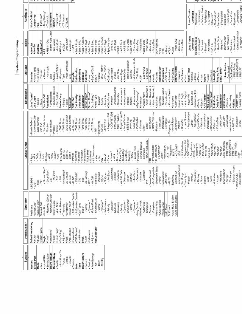
Syste
m P
rog
ram
min
g
Res
tart
SP
rog
Po
rtM
od
e•
Key
• H
ybrid
/PB
X•
Beh
indS
wtc
hB
oar
d R
enu
mM
ain
tain
Bu
sy•
Ena
ble
-
Aut
o B
usy
Tie
T
runk
s
- E
nabl
e
- D
isab
le•
Dis
able
Dat
eT
ime
Bac
k/R
esto
re•
Bac
kup
• R
esto
re•
Aut
o B
acku
p
- O
ff
- D
aily
-
Wee
kly
Def
ault
Num
beri
ng•
2-D
igit
• 3-
Dig
it•
Set
Up
Spa
ceS
ingl
e•
Line
s*•
Ext
ensi
ons*
• P
ools
*•
Gro
up P
age*
• G
rpC
allin
g*•
Adj
unct
s*•
Par
k*•
AR
S D
ialO
ut•
Rem
oteA
ccs
• D
SS
But
tons
*•
List
Dilr
ctN
oB
lock
• Li
nes
• E
xten
sion
s•
Adj
unct
sN
onLo
cal U
DP
Po
siti
on
s•
Dire
ct L
ine*
• Q
ueue
d C
all*
Qu
eued
Cal
l•
Hol
d R
tn
- R
etur
n to
Que
ue
- R
emai
n O
n H
old
• H
oldR
elea
se
- A
uto
Hol
d
- A
uto
Rel
ease
• T
hres
hold
• E
lvat
ePrio
r•
InQ
ue A
lert
*
- In
Que
Ale
rt E
nabl
e
- In
Que
Ale
rt D
isab
le•
Cal
l Typ
es
- D
ial 0
-
Prio
rity
-
Ope
rato
r*
- F
ollo
w/F
rwd
-
Una
ssig
nDID
-
Prio
rity
-
Ope
rato
r*
- Li
sted
Num
br
- P
riorit
y
- O
pera
tor*
-
QC
C E
xt
- R
etur
ning
-
Prio
rity
-
Ope
rato
r*
- G
rpC
over
ge
- P
riorit
y
- O
pera
tor*
• M
sg C
ente
r*•
Ext
ndC
ompl
t
- A
utom
atic
C
ompl
ete
-
Man
ual
C
ompl
ete
• R
etur
n R
ing
• Q
CC
Bac
kup
• V
oice
Ann
cH
old
Tim
erD
LC
Ho
ld•
Aut
o H
old
Ena
ble
• A
uto
Hol
d D
isab
le
LS
GS
/DS
1•
(DS
1)
- T
ype
-
T1
*
- G
roun
dSta
rt*
-
Loop
Sta
rt*
-
TIE
-
TIE
-PB
X*
-
Tol
l*
- S
56
- U
nequ
ippe
d
- A
ll G
roun
d
- A
ll Lo
op
- A
ll T
IE
- T
IE-P
BX
-
Tol
l
- S
56
- A
ll U
nequ
ip
- D
ID*
-
All
DID
-
S56
Dat
a
- D
irect
ion
-
Inty
pe
- O
utty
pe
- A
nsS
upv
-
Dis
conn
ect
-
Inm
ode
-
Out
mod
e
- A
ll S
56 D
ata
-
Dire
ctio
n
- In
type
-
Out
type
-
Ans
Sup
v
- D
isco
nnec
t
- In
mod
e
- O
utm
ode
-
PR
I
- F
ram
eFor
mat
-
D4
Com
patib
le
- E
xten
ded
Sup
er
Fra
me
-
Sup
pres
sion
-
AM
I-Z
CS
-
B8Z
S
- S
igna
ling
-
Rob
bed
Bit
-
Com
mon
Cha
nnel
-
Line
Com
p
- C
lock
Syn
c
- P
riorit
y
- P
rimar
y
- S
econ
dary
-
Ter
tiary
-
Non
e
- S
ourc
e
- Lo
op
- Lo
cal
-
Act
ivat
ion
-
Act
ive
-
Not
Act
ive
-
Cha
nnel
/Uni
t
- F
orei
gn
Exc
hang
e
- S
peci
al A
cces
s•
(4xx
GS
/LS
)
- G
roun
dSta
rt*
LS
*
• In
type
-
Win
k
- D
elay
-
Imm
ed
- A
uto
• O
utty
pe
- W
ink
-
Del
ay
- Im
med
-
Aut
o•
E&
M S
igna
l
- T
ype
1S
- T
ype
1C
- T
ype
5•
Inm
ode†
• O
utm
ode†
• D
ialto
ne†
• A
nsS
upvr
• D
isco
nnec
tT
T/L
S D
isc
• O
utM
ode†
• LS
Dis
conn
ect
-
Yes
-
No
DID
• B
lock
†
• T
ype
-
Imm
ed
- W
ink
• D
isco
nnec
t•
Exp
ectD
igit
• D
elet
eDig
it•
Add
Dig
its•
Sig
nalin
g
- R
otar
y
- T
ouch
Ton
e•
Inva
lDst
n
- S
end
to B
acku
p
Ext
ensi
on
- R
etur
n F
ast B
usy
PR
I•
Pho
neN
umbe
r•
B-C
hann
elG
rp
- B
Cha
nnel
s*
-
Line
s *†
-
Net
wor
kSer
v
- A
T&
T T
oll
-
Meg
acom
W
AT
S
- A
CC
UN
ET
S
DS
-
Sof
t Def
Net
w
- M
egac
om 8
00
- M
ULT
I QU
ES
T
- Lo
ng d
istn
ce
- 5E
SS
Loc
al
- O
UT
WA
TS
-
56/6
4 di
git
-
Virt
Priv
Net
-
INW
AT
S
- M
CI T
oll
-
MC
I PR
ISM
-
MC
I VN
ET
-
MC
I 800
-
MC
I 900
-
DM
S-1
00Lo
cal
-
DM
S-P
rivat
e
- D
MS-
OU
TWAT
S
- D
MS
-FX
-
DM
S-T
ieT
rk
- M
isc
-O
ther
• N
umbr
ToS
end
-
Ext
ensi
on O
nly
-
Bas
e N
umbe
r
with
Ext
-
Line
Tel
epho
ne
Num
ber
• T
est T
elN
um•
Pro
toco
l
- T
imer
s
- T
200
Tim
er
- T
203
Tim
er
- N
200
Cou
nter
-
N20
1 C
ount
er
- K
Cou
nter
-
T30
3 T
imer
-
T30
5 T
imer
-
T30
8 T
imer
-
T30
9 T
imer
-
T31
3 T
imer
-
T31
6 T
imer
-
TE
I•
Dia
lPla
nRtg
-
Ser
vice
-
AT
&T
Tol
l
- M
egac
om 8
00
- A
CC
UN
ET
SD
S
- S
oftD
efN
etw
-
MU
LTI Q
UE
ST
-
Meg
acom
WA
TS
- Lo
ng D
istn
ce
- 5E
SS
Loc
al
- IN
WA
TS
-
56/6
4 D
igtl
-
Virt
Priv
Net
-
Out
wat
s
- M
isc
-
Oth
er
-
Cal
lByC
all
-
DM
S-1
00 L
ocal
-
Pat
tern
s
- T
otal
Dig
its
- D
elet
eDig
its
- A
dd D
igits
• O
utgo
ing
Tbl
-
Net
wkS
elec
t
- S
peci
alS
erv
-
Pat
tern
-
Ope
rato
r
- Lo
cal O
pera
tor
-
Pre
subs
crib
ed
Car
rier
-
No
Ope
rato
r
- Ty
peO
fNum
ber
-
Nat
iona
l
- In
tern
atio
nal
-
Del
eteD
igit
-
CB
C S
ervi
ce
- P
atte
rns
-
Voi
ce/D
ata
-
Voi
ce O
nly
-
Dat
a O
nly
-
Voi
ce/D
ata
-
Net
wor
kSer
v
- A
T&
T T
oll
-
Meg
acom
W
AT
SA
CC
UN
ET
SD
S
Lin
esT
run
ks†
Lin
e C
op
y
• S
ingl
e
• B
lock
Dia
l Ou
tCd
†
Res
tric
tio
n
• U
nres
tric
ted
•
Out
war
d R
estr
ict
•
Tol
l Res
tric
tR
estr
ctC
op
y
• S
ingl
e
• B
lock
Acc
ou
nt*
BIS
/HF
AI*
Cal
l Pic
kUp
*V
oic
eSig
nl*
Ext
Sta
tus*
Gro
up
Pag
e*G
rou
p C
ove
r*G
rp C
allin
g*
• H
unt T
ype
-
Circ
ular
-
Line
ar
- M
ost I
dle
• D
elay
Ann
ce
- P
rimar
y
Ann
ounc
emen
ts
- S
econ
dary
A
nnou
ncem
ent
-
Ann
oucn
emen
t
Inte
rval
-
Rep
eat
A
nnou
ncem
ent
• G
rpC
over
age†
• M
essa
ge•
Que
ue A
larm
-
Ala
rm T
hres
hold
1
- A
larm
Thr
esho
ld 2
-
Ala
rm T
hres
hold
3•
Xtn
l Ale
rt•
Ove
rflo
w
- N
umbe
r B
ased
-
Tim
e B
ased
-
Pro
mpt
Bas
ed•
Mem
bers
*•
Line
/Poo
l*•
Gro
up T
ype
-
Aut
o Lo
gin
-
Aut
o Lo
gout
-
Inte
g V
MI
-
Gen
eric
VM
I•
Que
ue C
ontr
ol•
Prio
rity
• S
uppo
rtA
RS
Res
trct
Mic
Dis
able
*R
emo
te F
rwd
*A
uth
Co
de
Del
ay F
rwd
Trk
Tra
nsf
erC
ove
r D
elay
• P
rimar
y•
Sec
onda
ryH
otL
ine
Dis
pla
yPre
f•
Cal
ling
Nam
eC
lliN
Tra
nsf
er•
Ret
urn
Tim
e•
One
Tou
ch
- T
rans
fer
-
Man
ual
-
Aut
omat
ic
- H
old
• A
udib
le
- M
usic
OnH
old
-
Rin
gbac
k•
Typ
e
- V
oice
Ann
ounc
e
- R
ing
Cam
pO
nC
allP
arkR
tnD
elay
Rin
gC
allb
ack
Ext
Sta
tus
• H
otel
• G
rpC
all/C
MS
SM
DR
• F
orm
at
- B
asic
SM
DR
-
ISD
N S
MD
R•
Cal
l Len
gth
• C
all R
epor
t
- In
/Out
-
Out
Onl
y•
New
Pag
e•
Aut
h C
ode
-
Hom
e E
xten
sion
N
umbe
r
- A
utho
rizat
ion
Cod
e
- T
alk
Tim
e•
UD
P
- Lo
g In
/Out
-
Log
Non
eIn
sid
e D
ial
• In
side
• O
utsi
deR
emin
der
Srv
Un
assi
gn
ed•
QC
C Q
ueue
• E
xten
sion
• G
rp C
allin
gB
ehn
dS
wit
ch•
Tra
nsfe
r•
Con
fere
nce
• D
rop
Rec
allT
imer
• 35
0 m
s•
450m
s•
650
ms
• 1
sec
Ro
tary
• D
elay
• N
o D
elay
Inte
r-D
igit
Rin
gin
g F
req
Sec
DT
Tim
er
Allo
wL
ist
Allo
wT
o†
Dis
allo
wD
isal
low
To†
AR
S•
AR
S1+
7Dia
l
- W
ithin
Are
a C
ode
-
Not
With
in
Are
a C
ode
• A
RS
Inpu
t
- 6-
Dig
it
- A
rea
Cod
e†
-
Exc
hang
e†
-
1+7
†
• S
ub A
Poo
ls•
Sub
A F
RL
• S
ub A
Abs
orb
• S
ub A
Dig
it•
Sub
B S
tart
• S
ub B
Sto
p•
Sub
B P
ool
• S
ub B
FR
L•
Sub
B A
bsor
b•
Sub
B D
igit
• S
pecl
Num
ber
-
AR
S F
RL
-
AR
S D
igit
• D
ial 0
-
AR
S P
ool
-
AR
S F
RL
-
AR
S D
igits
• S
ub A
Dat
a
- V
oice
Onl
y
- D
ata
Onl
y
- V
oice
/Dat
a•
Sub
B D
ata
-
Voi
ce O
nly
-
Dat
a O
nly
-
Voi
ce/D
ata
UD
P R
ou
tin
g•
Poo
l•
FR
L•
Abs
orb
• D
igits
• D
ata
-
Voi
ce O
nly
-
Dat
a O
nly
-
Voi
ce/D
ata
Mu
sicO
nH
old
Ld
spkr
Pg
*F
ax•
Ext
ensi
on*
• M
sg W
aitin
g*•
Thr
esho
ldM
ain
tAla
rms
VM
S/A
A•
Tra
nsfe
rRtn
• T
T D
urat
ion
• T
T In
terv
al
CT
I Lin
k
G • • • • O E E S S T - - C P T H P Q Q L C • • •
L
ines
Tru
nks
Co
nti
nu
ed
- R
estr
ictio
n
- U
nres
tric
ted
-
Out
war
d R
estr
ict
-
Tol
l Res
tric
t
- A
RS
Res
trct
-
Allo
w L
ist*
-
Dis
allo
wLs
t*•
Bar
rierC
ode
-
SP
rog/
Mai
nt
- C
ode
Info
-
Cod
e Le
ngth
-
Cod
e E
ntry
-
Res
tric
tion
-
Unr
estr
icte
d
- O
utw
ard
Res
tric
t
L
ines
Tru
nks
Co
nti
nu
edR
emo
teA
cces
s•
Lin
esT
runk
s*
- D
edic
ated
-
Sha
red
-
No
Rem
ote
• N
on-T
IE
- B
arrie
rCod
e
- B
arrie
rCod
e
Req
uire
d
- B
arrie
rCod
e
Not
Req
uire
d
- R
estr
ictio
n
- U
nres
tric
ted
-
Out
war
d R
estr
ict
-
Tol
l Res
tric
t
L
ines
Tru
nks
C
on
tin
ued
-
DM
S-1
00Lo
cal
-
DM
S-P
rivat
e
- D
MS
-OU
TWA
TS
- D
MS
-FX
Sys
tem
Sys
Ren
um
ber
Op
erat
or
Lin
esT
run
ksE
xten
sio
ns
Op
tio
ns
Tab
les
Au
xEq
uip
Overview C-1
C0��������$� C
�'��'��, 4
Table C-1 defines LED status on the MLX-20L console. LED status is indicated on the LEDs next to the 20 buttons below the display area on the system programming console. LED status is simulated on the computer screen when you use SPM.
Table C-2 defines LED status on the DSS console. LED status is indicated on the red LED next to the 50 extension buttons.
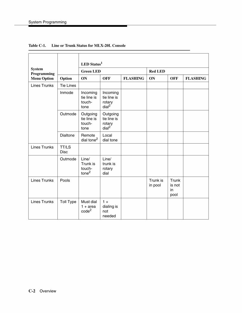
System Programming
C-2 Overview
Table C-1. Line or Trunk Status for MLX-20L Console
System Programming Menu Option
LED Status1
Green LED Red LED
Option ON OFF FLASHING ON OFF FLASHING
Lines Trunks Tie Lines
Inmode Incoming tie line is touch-tone
Incoming tie line is rotary dial2
Outmode Outgoing tie line is touch-tone
Outgoing tie line is rotary dial2
Dialtone Remote dial tone2
Local dial tone
Lines Trunks TT/LSDisc
Outmode Line/Trunk is touch-tone2
Line/trunk is rotary dial
Lines Trunks Pools Trunk is in pool
Trunk is not in pool
Lines Trunks Toll Type Must dial 1 + area code2
1 + dialing is not needed

LED Displays
Overview C-3
System Programming Menu Option
LED Status2
Green LED Red LED
Option ON OFF FLASHING ON OFF FLASHING
Lines Trunks Hold Disconct
Long-450 ms3
Short-50 ms
Lines Trunks LS-IDDelay
LS-ID Delay is on
LS-ID Delay is off2
Extensions Lines Trunks
Line/trunk or pool is assigned to button
Line/trunk or pool is not assigned to button
Trunk is assigned to a pool
1 LED Status is indicated on LEDs next to the 20 buttons below the display area of the system programming console, or simulated on the computer screen when using SPM.
2 LED Status is indicated on LEDs next to the 20 buttons below the display area of the system programming console, or simulated on the computer screen when using SPM.
3 This is the factory setting
Table C-1. Line or Trunk Status for MLX-20L Console—Continued

System Programming
C-4 Overview
Table C-2. Telephone Feature Status for DSS Console Only
System Programming Menu Option
Red LED Status
Option ON OFF FLASHING WINK
Extensions Account (FACE)
Forced Account Code Entry assigned
Forced Account Code Entry not assigned1
Extensions BIS/HFAI Telephone has BIS/HFAI ability (factory setting analog multiline telephones)
Other
Extensions Call Pickup Telephone is assigned to Call Pickup Group
Telephone is not assigned to Call Pickup Group1
Extensions VoiceSignl Voice Announce to Busy assigned
Voice Announce to Busy not assigned1
Extensions Ext Status Extension Status assigned
Extension Status not assigned
Extension Status can be assigned
Extensions Group Page
Telephone is in group
Telephone is not in group1
Extensions Group Cover
Telephone is in coverage group
Telephone is not in coverage group1
Extensions Group Calling Members
Telephone is assigned to group
Telephone is not assigned to group1
Extensions Mic Disable Telephone microphone is disabled
Telephone microphone is enabled
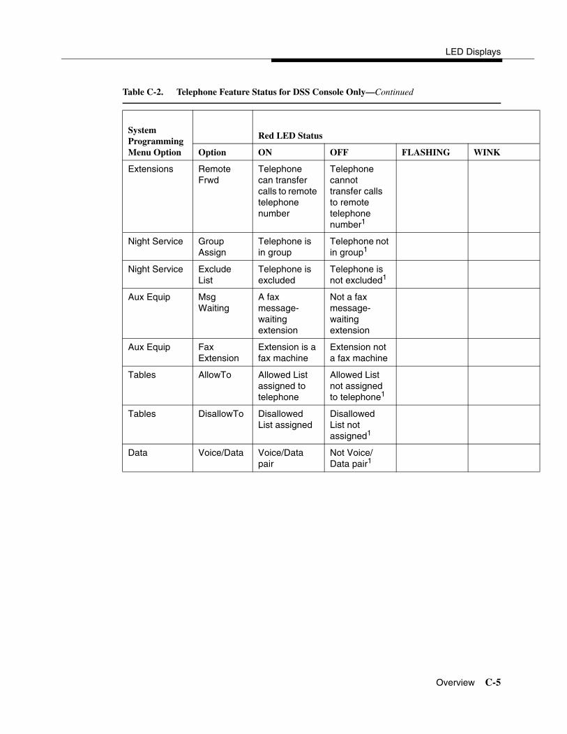
LED Displays
Overview C-5
System Programming Menu Option
Red LED Status
Option ON OFF FLASHING WINK
Extensions Remote Frwd
Telephone can transfer calls to remote telephone number
Telephone cannot transfer calls to remote telephone number1
Night Service Group Assign
Telephone is in group
Telephone not in group1
Night Service Exclude List
Telephone is excluded
Telephone is not excluded1
Aux Equip Msg Waiting
A fax message-waiting extension
Not a fax message-waiting extension
Aux Equip Fax Extension
Extension is a fax machine
Extension not a fax machine
Tables AllowTo Allowed List assigned to telephone
Allowed List not assigned to telephone1
Tables DisallowTo Disallowed List assigned
Disallowed List not assigned1
Data Voice/Data Voice/Data pair
Not Voice/Data pair1
Table C-2. Telephone Feature Status for DSS Console Only—Continued

System Programming
C-6 Overview
System Programming Menu Option
Red LED Status
Option ON OFF FLASHING WINK
Operator Direct Trunk Queued Call
Operator position
Other Can be assigned as operator position
Operator Queued Call Message Center
Message Center position
Other Can be assigned as Message Center
Operator In Queue Alert
Position receives In-Queue Alert for Thresh. 3
Other Position receives In-Queue Alert for Thresh. 1
Position receives In-Queue Alert for Thresh. 2
1 This is the factory setting.
Table C-2. Telephone Feature Status for DSS Console Only—Continued
General Feature Use Information D-1
DGeneral Feature Use and Telephone Programming D
This appendix contains information on the general use of features for the MLX, ETR, MLS, analog multiline, and single-line telephones. It covers telephone and operator features and the acceptable programming codes for each. It also describes how to program these features on MLX, ETR, MLS, and analog multiline telephones.
General Feature Use Information 4
The following sections provide general instructions for feature use on MLX, ETR, MLS, analog multiline, and single-line telephones. Features can be used in the following ways:
� Press a dedicated feature button.
� Press a programmed button.
Fixed Features 4
All multiline telephones have a group of dedicated (or fixed) feature buttons that are programmed and labeled at the factory. The functions of these buttons, which include Conf, Transfer, and Speaker, cannot be changed. Press the button for the feature you want to use.

System Programming
D-2 General Feature Use Information
Programmed Buttons 4
Any unlabeled line button on multiline telephones can be programmed with a feature for one-touch activation. See Tables D-4 through D-8 for additional information about programming features onto line buttons.
Some features, such as Auto Dial, must be programmed onto line buttons in order to function. Other features, such as Privacy, are best used if programmed onto line buttons—the LED next to the line button provides visual indication that the feature is in use. The following features must be programmed onto line buttons:
� Auto Answer All
� Auto Answer Headset
� Auto Dial
� Barge-In
� Coverage
— Group Coverage
— Primary Coverage
— Secondary Coverage
— Coverage Off
— Coverage VMS Off
� Do Not Disturb
� Extension Status-Agent Login/Logout
� Feature Button (analog multiline telephones only)
� Headset/Handset Mute
� Headset Status
� Headset Hang Up
� Notify
� Posted Message (available from display on MLX display telephones)
� Saved Number Dial
� Service Observing
� Signal

General Feature Use and Telephone Programming
Telephone and Operator Features D-3
Feature Codes 4
Feature codes are 1-, 2-, and 3-digit codes that activate features. A feature code is used by first pressing the dedicated Feature button on MLX telephones, pressing a programmed Feature button on analog multiline telephones, or dialing # on single-line telephones. Each of these methods sends a signal to the system that a feature code is about to be dialed. When the code is dialed, the feature is activated.
NOTE:Queued Call Console (QCC) system operators cannot use feature codes.
The following features can be used only by dialing feature codes:
� Pickup
� Forward/Follow Me—Cancel One
� Forward/Follow Me—Cancel All
� Message Cancel
� Personal Speed Dial
� System Speed Dial
NOTE:Pressing the Conf, Transfer, Speaker, or Feature button while activating a feature cancels the process. Pressing any other button, such as the Mute, HFAI, Message Status, DSS Page, More, Message, Clock, analog multiline display keys, or analog multiline disconnect button does not cancel the feature activating process.
Telephone and Operator Features 4
Tables D-1, D-2, and D-3 list the telephone and operator features that can be assigned to telephones or consoles either through centralized telephone programming or by users from their telephones.

System Programming
D-4 Telephone and Operator Features
Tab
le D
-1.
Tel
epho
ne a
nd O
pera
tor
Fea
ture
s fo
r M
LX
Tel
epho
nes
Fea
ture
Pro
g C
ode
Fea
ture
C
ode
2-L
ine
Dis
play
7-L
ine
Dis
play
ML
X-
5D/1
0DM
LX
-28
DM
LX
-20
LM
LX
-5/
10
Acc
ount
Cod
e E
ntry
*82
82
+ c
ode
Acct
AccountCode
K
P B
K P
BK
P B
K P
Ala
rm1
*759
Alarm
Alarm
K
P B
K P
B
Ala
rm C
lock
AlClk
Alarm Clock
K
P B
K P
BK
P B
Aut
horiz
atio
n C
ode
*80
80
Auth
Auth Code
K
P B
K
P B
K
P B
K
P B
Aut
o A
nsw
er A
ll*754
AutoAns All
Aut
o A
nsw
er In
terc
om*753
AutoAnsIcom
Aut
o D
ial
Insi
de (
ext.,
gro
up,
zone
)O
utsi
de
*22
+ ex
t. no
.
*21
+ te
l. no
.
AutoD
In
Out
Auto Dial
Inside
Outside
K P
BK
P B
K P
BK
P B
Aut
omat
ic L
ine
Sel
ectio
nB
egin
Seq
uenc
e E
nd S
eque
nce
*14
**14
K P
BK
P B
K P
BK
P B
Bar
ge-ln
1,2
*58
Bar
ge
Bar
ge In
K
P B
K P
BK
P B
K P
B
Cal
lbac
k A
utom
atic
On
Off
Sel
ectiv
eC
ance
l sel
ectiv
e
*12
**12
*55
55
*55
CbckA
On
Off
CbckS
Cback Auto
On
Off
Cback Sel
K P
BK
P B
K P
BK
P B
Cal
ler
ID N
umbe
r/N
ame
Tog
gle
But
ton
*763
763
C
alle
r’s
num
ber/
nam
eC
alle
r’s n
umbe
r/na
me
K P
BK
P B
K P
BK
P B
Cam
p-O
n*57
57
Camp
Camp On
K
P B
K P
BK
P B
K P
B
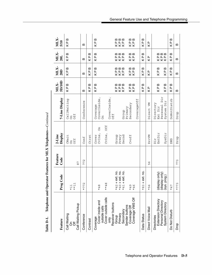
General Feature Use and Telephone Programming
Telephone and Operator Features D-5
Cal
l Wai
ting
On
Off
Cal
l Wai
ting
Pic
kup
*11
**11
87
CWait
On
Off
CallWaiting
On
Off
K P
BK
P B
K P
BK
P B
Con
fere
nce
*772
772
Conf
Conference
B
B B
B
Con
tras
tCtrst
K
P B
K P
BK
P B
Cov
erag
eC
over
insi
de a
nd
outs
ide
calls
Cov
er o
utsi
de c
alls
on
lyR
ecei
ver
butto
nsG
roup
Prim
ary
Sec
onda
ryS
ende
r bu
ttons
Cov
erag
e O
ffC
over
age
VM
S O
ff
*48
**48
*42
+ e
xt. n
o.*40
+ e
xt. n
o.*41
+ e
xt. n
o.
*49
*46
Cover
CvIns, On
CvIns, Off
Group
Prmry
Secnd
Cvoff
Coverage
CoverInside,
On
CoverInside,
Off
Group
Primary
Secondary
CoverageOff
K P
B
K P
BK
P B
K P
B
K P
BK
P B
K P
B
K P
BK
P B
K P
B
K P
BK
P B
K P
B
K P
BK
P B
K P
B
K P
BK
P B
K P
B
K P
BK
P B
K P
B
K P
BK
P B
Dat
a S
tatu
s*83
+ e
xt. n
o.K
P B
K P
BK
P B
K P
B
Dire
ct V
oice
Mai
l*56
56
DrcVM
Direct VM
K
PK
PK
PK
P
Dire
ctor
ies
Ext
ensi
on D
irect
ory
Per
sona
l Dire
ctor
y S
yste
m D
irect
ory
(dis
play
onl
y)(d
ispl
ay o
nly)
(sys
. pro
g.)
Dir
ExtDir
SysDir
Directory
Ext Dir
Personal Dir
System Dir
K P
B
K P
B
K P
B
K P
B
K P
BK
P B
K P
B
Do
Not
Dis
turb
*47
DND
DoNotDistrb
K
P B
K P
BK
P B
K P
B
Dro
p*773
773
Drop
Drop
B
B B
B
Tab
le D
-1.
Tel
epho
ne a
nd O
pera
tor
Fea
ture
s fo
r M
LX
Tel
epho
nes—
Con
tinu
ed
Fea
ture
Pro
g C
ode
Fea
ture
C
ode
2-L
ine
Dis
play
7-L
ine
Dis
play
ML
X-
5D/1
0DM
LX
-28
DM
LX
-20
LM
LX
-5/
10

System Programming
D-6 Telephone and Operator Features
Ext
ensi
on S
tatu
sD
irect
-Lin
e C
onso
le1
Sta
tus
Off
Sta
tus
1
Sta
tus
2
Tel
epho
nes
(roo
ms
or a
gent
s)S
tatu
s O
ffS
tatu
s 1
Sta
tus
2
*760
*761
*762
*45
*44
760
+ D
SS
bu
tton
761
+ D
SS
bu
tton
762
+ D
SS
butto
n
*44
45
44
OPES, ESOff
OPES, ES1
OPES, ES2
ES, ES1
ES, ES2
OperatorES,
ESOff
OperatorES,
ES1
OperatorES,
ES2
ES Status,
ES1
ES Status,
ES2
K P
B
K P
B
K P
B
K P
B
K P
BK
P B
Fea
ture
But
ton
*20
Feature Btn
Tab
le D
-1.
Tel
epho
ne a
nd O
pera
tor
Fea
ture
s fo
r M
LX
Tel
epho
nes—
Con
tinu
ed
Fea
ture
Pro
g C
ode
Fea
ture
C
ode
2-L
ine
Dis
play
7-L
ine
Dis
play
ML
X-
5D/1
0DM
LX
-28
DM
LX
-20
LM
LX
-5/
10

General Feature Use and Telephone Programming
Telephone and Operator Features D-7
For
war
d an
d F
ollo
w M
eA
ctiv
ate
For
war
d (in
side
) R
emot
e C
all F
orw
ard
(out
side
) C
entr
ex T
rans
fer
vi
a R
emot
e C
all
For
war
d
Fol
low
Me
Can
cel
Can
cel s
endi
ng fr
om
your
tele
phon
e C
ance
l sen
ding
from
on
e ex
tens
ion
Can
cel s
endi
ng fr
om
all e
xten
sion
s
*33
*33
*33
+ d
ial-o
ut
code
or *
+
optio
nal
Pau
ses
+ te
l. no
. + #
33
+ e
xt.
no.
33
+ te
l no.
34
+ e
xt.
no.
33
+ y
our
ext.
no.
*34
+ e
xt.
no.
*34*
Forwd
Forwd
FlwMe
Forward
Forward
Follow Me
CanclFollow
(Q
CC
onl
y)
CanclFollow
(Q
CC
onl
y)
K P
BK
P B
K P
BK
P B
Tab
le D
-1.
Tel
epho
ne a
nd O
pera
tor
Fea
ture
s fo
r M
LX
Tel
epho
nes—
Con
tinu
ed
Fea
ture
Pro
g C
ode
Fea
ture
C
ode
2-L
ine
Dis
play
7-L
ine
Dis
play
ML
X-
5D/1
0DM
LX
-28
DM
LX
-20
LM
LX
-5/
10
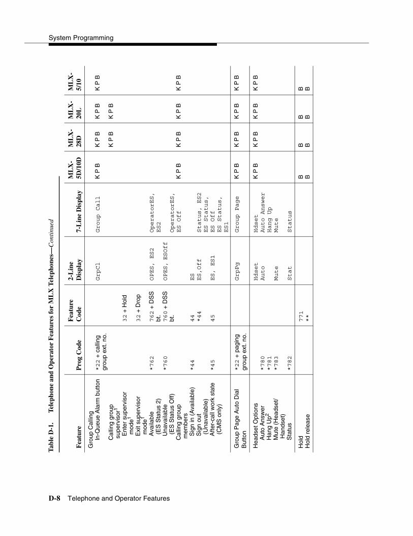
System Programming
D-8 Telephone and Operator Features
Gro
up C
allin
gln
-Que
ue A
larm
but
ton
Cal
ling
grou
p su
perv
isor
1
Ent
er s
uper
viso
r m
ode1
Exi
t sup
ervi
sor
mod
e1
Ava
ilabl
e (E
S S
tatu
s 2)
Una
vaila
ble
(ES
Sta
tus
Off)
Cal
ling
grou
p m
embe
rsS
ign
in (
Ava
ilabl
e)
Sig
n ou
t (U
nava
ilabl
e)A
fter-
call
wor
k st
ate
(CM
S o
nly)
*22
+ c
allin
g gr
oup
ext.
no.
*762
*760
*44
*45
32
+ H
old
32
+ D
rop
762
+ D
SS
bt
.760
+ D
SS
bt
.
44
*44
45
GrpCl
OPES, ES2
OPES, ESOff
ES
ES,Off
ES, ES1
Group Call
OperatorES,
ES2
OperatorES,
ES Off
Status, ES2
ES Status,
ES Off
ES Status,
ES1
K P
B
K P
B
K P
B
K P
B
K P
B
K P
B
K P
B
K P
B
K P
B
K P
B
Gro
up P
age
Aut
o D
ial
But
ton
*22
+ p
agin
g gr
oup
ext.
no.
GrpPg
Group Page
K
P B
K P
BK
P B
K P
B
Hea
dset
Opt
ions
Aut
o A
nsw
er
Han
g U
p2
Mut
e (H
eads
et/
Han
dset
) S
tatu
s
*780
*781
*783
*782
Hdset
Auto
Mute
Stat
Hdset
Auto Answer
Hang Up
Mute
Status
K P
BK
P B
K P
BK
P B
Hol
dH
old
rele
ase
771
**
B B
B BB B
B B
Tab
le D
-1.
Tel
epho
ne a
nd O
pera
tor
Fea
ture
s fo
r M
LX
Tel
epho
nes—
Con
tinu
ed
Fea
ture
Pro
g C
ode
Fea
ture
C
ode
2-L
ine
Dis
play
7-L
ine
Dis
play
ML
X-
5D/1
0DM
LX
-28
DM
LX
-20
LM
LX
-5/
10
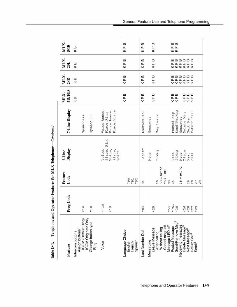
General Feature Use and Telephone Programming
Telephone and Operator Features D-9
Inte
rcom
but
tons
Ass
ign
butto
ns2
ICO
M (
Def
ault
Rin
g)
ICO
M O
rigin
ate
Onl
y C
hang
e bu
tton
type
Rin
g
Voi
ce
*16
*18
**19
*19
Voice,
Place, Ring
Voice,
Place,
Voice
SysAccess
SysAcc-00
Voice Annce,
Place,Ring
Voice Annce,
Place,Voice
K B
K B
K B
K B
Lang
uage
Cho
ice
Eng
lish
Fre
nch
Spa
nish
790
791
792
K P
BK
P B
K P
BK
P B
Last
Num
ber
Dia
l *84
84
Last#*
LastNumDial
K
P B
K P
BK
P B
K P
B
Mes
sagi
ngLe
ave
Mes
sage
Afte
r ca
lling
With
out c
allin
gC
ance
l msg
. lef
tM
essa
ge L
ED
off
Pos
ted
Mes
sage
Sen
d/R
emov
e M
sg1
Rec
eivi
ng m
essa
ges
Del
ete
Mes
sage
3
Nex
t Mes
sage
3
Ret
urn
Cal
l3
Scr
oll3
*25
*54
*751
*38
*26
*28
*27
*29
25
53
+ e
xt n
o.*53
+ e
xt
no.
54
38
+ e
xt n
o.
26
28
27
29
Msgs
LvMsg
Post
SdMsg
Msgs
Dlete
Next
Call
Messages
Msg Leave
Posted Msg
Send/RmvMsg
Messages
Delete Msg
Next Msg
Return Call
K P
B
K P
BK
P B
K P
BK
P B
K P
B
K P
B
K P
BK
P B
K P
BK
P B
K P
BK
P B
K P
B
K P
BK
P B
K P
BK
P B
K P
BK
P B
K P
B
K P
BK
P B
Tab
le D
-1.
Tel
epho
ne a
nd O
pera
tor
Fea
ture
s fo
r M
LX
Tel
epho
nes—
Con
tinu
ed
Fea
ture
Pro
g C
ode
Fea
ture
C
ode
2-L
ine
Dis
play
7-L
ine
Dis
play
ML
X-
5D/1
0DM
LX
-28
DM
LX
-20
LM
LX
-5/
10
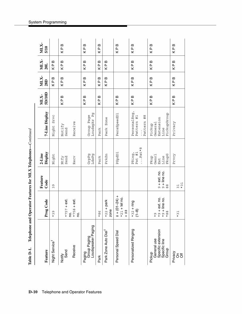
System Programming
D-10 Telephone and Operator Features
Nig
ht S
ervi
ce1
*39
39
Night
Night Srvc
K
P B
K P
B
Not
ify Sen
d
Rec
eive
*757
+ e
xt.
no.
*758
+ e
xt.
no.
Ntfy
Send
Recv
Notify
Send
Receive
K P
BK
P B
K P
BK
P B
Pag
ing
Gro
up P
agin
gLo
udsp
eake
r P
agin
gGrpPg
LdsPg
Group Page
Loudspkr Pg
K P
BK
P B
K P
BK
P B
Par
k*86
Park
Park
K
P B
K P
BK
P B
K P
B
Par
k Z
one
Aut
o D
ial1
*22
+ p
ark
zone
PrkZn
Park Zone
K
P B
K P
B
Per
sona
l Spe
ed D
ial
# +
(01
–24)
+*21
+ te
l no.
+ ##
PSpdDl
PersSpeedDl
K
P B
K P
B
Per
sona
lized
Rin
ging
*32
+ r
ing
(1–8
)PRing,
Pat #1
...Pat*8
PersonalRng,
Pattern #1
...
Pattern #8
K P
BK
P B
K P
BK
P B
Pic
kup
Gen
eral
use
Spe
cific
ext
ensi
onS
peci
fic li
neG
roup
*9
*9
+ e
xt. n
o.*9
+ li
ne n
o.*88
9 +
ext
. no.
9 +
line
no.
88
Pkup
Genrl
Ext
Line
PkupG
Pickup
General
Extension
Line
PickupGroup
K P
BK
P B
K P
BK
P B
Priv
acy
On
Off
*31
31
*31
Prvcy
Privacy
K
P B
K P
BK
P B
K P
B
Tab
le D
-1.
Tel
epho
ne a
nd O
pera
tor
Fea
ture
s fo
r M
LX
Tel
epho
nes—
Con
tinu
ed
Fea
ture
Pro
g C
ode
Fea
ture
C
ode
2-L
ine
Dis
play
7-L
ine
Dis
play
ML
X-
5D/1
0DM
LX
-28
DM
LX
-20
LM
LX
-5/
10

General Feature Use and Telephone Programming
Telephone and Operator Features D-11
Rec
all
*775
775
Recll
Recall
K
P B
K P
BK
P B
K P
B
Rem
inde
r S
ervi
ceS
et4
Ope
rato
r S
et1,
4
Can
cel
Ope
rato
r C
ance
l1
Mis
sed1
*81
**81
*752
81
+ ti
me
+
A o
r P
81
+ e
xt.
no.+
tim
e +
A
or P
§
*81
*81
+ e
xt.
no.
Rmind
Set
Cancl
Missd
Reminder
Set
Cancel
Missed
K P
BK
P B
K P
BK
P B
Rin
ging
/Idle
Lin
e P
refe
renc
eO
n
Off
*343
*344
LnPrf, On
LnPrf, Off
Line
Preference,
On
Line
Preference,
Off
K P
BK
P B
K P
BK
P B
Tab
le D
-1.
Tel
epho
ne a
nd O
pera
tor
Fea
ture
s fo
r M
LX
Tel
epho
nes—
Con
tinu
ed
Fea
ture
Pro
g C
ode
Fea
ture
C
ode
2-L
ine
Dis
play
7-L
ine
Dis
play
ML
X-
5D/1
0DM
LX
-28
DM
LX
-20
LM
LX
-5/
10
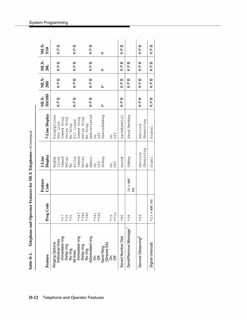
System Programming
D-12 Telephone and Operator Features
Rin
ging
Opt
ions
Indi
vidu
al li
nes
Imm
edia
te r
ing
Del
ay r
ing
No
ring
All
lines
Imm
edia
te r
ing
Del
ay r
ing
No
ring
Abb
revi
ated
rin
gO
nO
ffS
end
Rin
g (S
hare
d S
A)
On
Off
*37
*36
*35
*347
*346
*345
*341
*342
*15
**15
RngOp
1Line
Immed
Delay
No
AllLn
Immed
Delay
No
Abbrv
On
Off
ShRng
On
Off
RingOptions
One Line
Immed Ring
Delay Ring
No Ring
All Lines
Immed Ring
Delay Ring
No Ring
Abbreviated
On
Off
SharedSARng
On
Off
K P
B
K P
B
K P
B
P
K P
B
K P
B
K P
B
P
K P
B
K P
B
K P
B
P
K P
B
K P
B
K P
B
P
Sav
ed N
umbe
r D
ial
*85
Save#
SaveNumDial
K
P B
K P
BK
P B
K P
B
Sen
d/R
emov
e M
essa
ge1
*38
38
+ e
xt.
no.
SdMsg
Send/RmvMsg
K
P B
K P
B
Ser
vice
Obs
ervi
ng2
*59
Service
Observing
Service
Observing
K
P B
K P
BK
P B
K P
B
Sig
nal (
man
ual)
*23
+ e
xt. n
o.Signl
Signal
K
P B
K P
BK
P B
K P
B
Tab
le D
-1.
Tel
epho
ne a
nd O
pera
tor
Fea
ture
s fo
r M
LX
Tel
epho
nes—
Con
tinu
ed
Fea
ture
Pro
g C
ode
Fea
ture
C
ode
2-L
ine
Dis
play
7-L
ine
Dis
play
ML
X-
5D/1
0DM
LX
-28
DM
LX
-20
LM
LX
-5/
10

General Feature Use and Telephone Programming
Telephone and Operator Features D-13
Sys
tem
Acc
ess
butto
nsA
ssig
n bu
ttons
2
SA
(D
efau
lt R
ing)
S
A O
rigin
ate
Onl
yS
hare
d S
A
Cha
nge
type
(S
A o
r S
hare
d S
A)
Rin
g V
oice
*16
*18
*17
+ p
rimar
y ex
t. no
.
**19
*19
SysAccess
SysAcc-00
ShareSysAcc
PP
PP
Sys
tem
Spe
ed D
ial
*24
+ c
ode
( 600-729
)600-729
SpdDl
SysSpeedDl
K
P B
K P
BK
P B
K
P B
Tra
nsfe
r *774
774
Trans
Transfer
B
B B
B
Voi
ce A
nnou
nce
On
Off
VA
on
Idle
Onl
y
*10
**10
*131
Voice
On
Off
Idle
Voice Annce
On
Off
Idle
K P
BK
P B
K P
BK
P B
1S
yste
m o
pera
tor
feat
ure
only
.
2C
entr
aliz
ed te
leph
one
prog
ram
min
g on
ly.
3D
ispl
ay te
leph
ones
onl
y. P
rogr
amm
ing
and
feat
ure
code
s ar
e us
ed w
ith a
nalo
g m
ultil
ine,
ET
R, a
nd M
LS te
leph
ones
.
4E
nglis
h on
ly: t
ime
is 1
2-ho
ur (
0100
–125
9) +
2 (
A)
or 7
(P
). F
renc
h an
d S
pani
sh: t
ime
is 2
4-ho
ur (
0000
–235
9).
Tab
le D
-1.
Tel
epho
ne a
nd O
pera
tor
Fea
ture
s fo
r M
LX
Tel
epho
nes—
Con
tinu
ed
Fea
ture
Pro
g C
ode
Fea
ture
C
ode
2-L
ine
Dis
play
7-L
ine
Dis
play
ML
X-
5D/1
0DM
LX
-28
DM
LX
-20
LM
LX
-5/
10

System Programming
D-14 Telephone and Operator Features
Table D-2. Telephone and Operator Features for Analog Multiline and Single-Line Telephones
Feature Prog CodeFeature Code
2-Line Display
Analog Multiline
Single-Line
Account Code Entry *82 82 + code Acct K P B K P
Alarm1 *759 Alarm
Alarm Clock AlClk K P B
Authorization Code *80 80 Auth K P B K P B
Auto Answer All *754
Auto Answer Intercom *753
Auto Dial Inside (ext., group, zone)Outside
*22 + ext. no.
*21 + tel. no.
AutoD In
Out
K P B K P B
Automatic Line SelectionBegin SequenceEnd Sequence
*14 **14
K P B K P B
Barge-ln1,2 *58 Barge K P B K P B
CallbackAutomatic
OnOff
SelectiveCancel selective
*12 **12 *55 55
*55
CbckA On Off CbckS
K P B K P B
Caller ID Number/Name Toggle Button
*763 763 Caller’s number/name
K P B K P B
Camp-On *57 57 Camp K P B K P B
Call WaitingOnOff
Call Waiting Pickup
*11 **11
87
CWait On Off
K P B K P B
Conference *772 772 Conf B B
Contrast Ctrst K P B

General Feature Use and Telephone Programming
Telephone and Operator Features D-15
CoverageCover inside and outside callsCover outside calls only
Receiver buttonsGroupPrimarySecondary
Sender buttonsCoverage OffCoverage VMS Off
*48
**48
*42 + ext. no.*40 + ext. no.*41 + ext. no.
*49 *46
Cover CvIns, On
CvIns, Off
Group Prmry Secnd
Cvoff
K P B
K P BK P BK P B
K P BK P B
K P B
K P BK P BK P B
K P BK P B
Data Status *83 + ext. no. K P B K P B
Direct Voice Mail *56 56 DrcVM K P K P
Directories Extension Directory Personal Directory System Directory
(display only)(display only)(sys. prog.)
Dir ExtDir
SysDir
K P B
K P B
Do Not Disturb *47 DND K P B K P B
Drop *773 773 Drop B B
Extension StatusDirect-Line Console1
Status Off
Status 1
Status 2
Telephones(rooms or agents)
Status OffStatus 1 Status 2
*760
*761
*762
*45 *44
760 + DSS button761 + DSS button762 + DSSbutton
*44 45 44
OPES, ESOff
OPES, ES1
OPES, ES2
ES, ES1 ES, ES2
K P B K P B
Feature Button *20
Table D-2. Telephone and Operator Features for Analog Multiline and Single-Line Telephones—Continued
Feature Prog CodeFeature Code
2-Line Display
Analog Multiline
Single-Line

System Programming
D-16 Telephone and Operator Features
Forward and Follow MeActivate
Forward (inside) Remote Call Forward (outside) Centrex Transfer
via Remote Call Forward
Follow MeCancel
Cancel sending from your telephone Cancel sending from one extensionCancel sending from all extensions
*33 *33
*33 + dial-out code or * + optional Pauses + tel. no. + #
33 + ext. no.33 + tel no.
34 + ext. no.33 + your ext. no.*34 + ext. no.*34*
Forwd Forwd
FlwMe
K P B K P B
Group Callingln-Queue Alarm button
Calling group supervisor1
Enter supervisor mode1
Exit supervisor mode1
Available (ES Status 2)Unavailable (ES Status Off)
Calling group membersSign in (Available) Sign out (Unavailable)After-call work state (CMS only)
*22 + calling group ext. no.
*762
*760
*44
*45
32 + Hold
32 + Drop
762 + DSS bt.760 + DSS bt.
44 *44
45
GrpCl
OPES, ES2
OPES, ESOff
ES ES,Off
ES, ES1
K P B
K P B
K P B
K P B
Group Page Auto Dial Button
*22 + paging group ext. no.
GrpPg K P B K P B
HoldHold release
771 **
BB
BB
Table D-2. Telephone and Operator Features for Analog Multiline and Single-Line Telephones—Continued
Feature Prog CodeFeature Code
2-Line Display
Analog Multiline
Single-Line

General Feature Use and Telephone Programming
Telephone and Operator Features D-17
Intercom buttonsAssign buttons2
ICOM (Default Ring) ICOM Originate Only
Change button typeRing
Voice
*16 *18
**19
*19
Voice, Place, Ring Voice, Place, Voice
K B K B
Language ChoiceEnglishFrenchSpanish
790 791 792
K P B K P B
Last Number Dial *84 84 Last#* K P B K P B
MessagingLeave Message
After callingWithout calling
Cancel msg. leftMessage LED off (for non-display telephones)Message operation mode (for display telephones)3
Posted MessageSend/Remove Msg1
Receiving messagesDelete Message4
Next Message4
Return Call4
Scroll4
*25
*54
*54
*751 *38
*26 *28 *27 *29
25 53 + ext no.*53 + ext no.
54
54
38 + ext no.
26 28 27 29
Msgs LvMsg
Post SdMsg
Msgs Dlete Next Call
K P B
K P BK P B
K P BK P BK P B
K P B
K P BK P B
Night Service1 *39 39 Night
NotifySend
Receive
*757 + ext. no.*758 + ext. no.
Ntfy Send
Recv
K P B K P B
PagingGroup PagingLoudspeaker Paging
GrpPg LdsPg
K P B K P B
Park *86 Park K P B K P B
Table D-2. Telephone and Operator Features for Analog Multiline and Single-Line Telephones—Continued
Feature Prog CodeFeature Code
2-Line Display
Analog Multiline
Single-Line

System Programming
D-18 Telephone and Operator Features
Park Zone Auto Dial1 *22 + park zone
PrkZn
Personal Speed Dial # + (01–24) +*21 + tel no.+ ##
PSpdDl K P B K P B
Personalized Ringing *32 + ring(1–8)
PRing, Pat #1 ...Pat*8
K P B K P B
PickupGeneral useSpecific extensionSpecific lineGroup
*9 *9 + ext. no.*9 + line no.*88
9 + ext. no.9 + line no.88
Pkup Genrl Ext Line PkupG
K P B K P B
PrivacyOnOff
*31 31 *31
Prvcy K P B K P B
Recall *775 775 Recll K P B K P B
Reminder ServiceSet5
Operator Set1,5
CancelOperator Cancel1
Missed1
*81
**81
*752
81 + time + A or P 81 + ext. no.+ time + A or P *81 *81 + ext. no.
Rmind Set
Cancl
Missd
K P B K P B
Ringing/Idle Line Preference
OnOff
*343 *344
LnPrf, On LnPrf, Off
K P B K P B
Table D-2. Telephone and Operator Features for Analog Multiline and Single-Line Telephones—Continued
Feature Prog CodeFeature Code
2-Line Display
Analog Multiline
Single-Line

General Feature Use and Telephone Programming
Telephone and Operator Features D-19
Ringing OptionsIndividual lines
Immediate ringDelay ringNo ring
All linesImmediate ringDelay ringNo ring
Abbreviated ringOnOff
Send Ring (Shared SA)OnOff
*37 *36 *35
*347 *346 *345
*341 *342
*15 **15
RngOp 1Line Immed Delay No AllLn Immed Delay No Abbrv On Off ShRng
On Off
K P B
K P B
K P B
P
K P B
K P B
K P B
P
Saved Number Dial *85 Save# K P B K P B
Send/Remove Message1 *38 38 + ext. no.
SdMsg
Signal (manual) *23 + ext. no. Signl K P B K P B
System Access buttonsAssign buttons2
SA (Default Ring) SA Originate OnlyShared SA
Change type (SA or Shared SA)Ring Voice
*16 *18 *17 + primary ext. no.
**19 *19
P P
Table D-2. Telephone and Operator Features for Analog Multiline and Single-Line Telephones—Continued
Feature Prog CodeFeature Code
2-Line Display
Analog Multiline
Single-Line

System Programming
D-20 Telephone and Operator Features
System Speed Dial *24 + code(600-729)
600-729 SpdDl K P B K P B
Transfer *774 774 Trans B B
Voice Announce to BusyOn Off
*10 **10
Voice On Off
K P B K P B
1 System operator feature only.
2 Centralized telephone programming only.
3 For analog multiline display telephone users, pressing *54 enters/exits Message operation mode. Analog multiline telephones return to normal call handling after 15 seconds if the user has no messages. If the user has messages, he or she must delete the messages or use the feature code or programmed button to exit Message operation.
4 Display telephones only. Programming and feature codes are used with analog multiline, ETR, and MLS telephones.
5 English only: time is 12-hour (0100–1259) + 2 (A) or 7 (P). French and Spanish: time is 24-hour (0000–2359).
Table D-2. Telephone and Operator Features for Analog Multiline and Single-Line Telephones—Continued
Feature Prog CodeFeature Code
2-Line Display
Analog Multiline
Single-Line

General Feature Use and Telephone Programming
Telephone and Operator Features D-21
Tab
le D
-3.
Tel
epho
ne a
nd O
pera
tor
Fea
ture
s fo
r E
TR
and
ML
S T
elep
hone
s
Fea
ture
Pro
g C
ode
Fea
ture
C
ode
ET
R D
ispl
ayM
LS
Dis
play
ET
RM
LS
Acc
ount
Cod
e E
ntry
*82
82
+ c
ode
Acct:
Acct?
K
P B
K P
B
Aut
horiz
atio
n C
ode
*80
80
Auth:
Auth?
K
P B
K
P B
Aut
o D
ial
Insi
de (
ext.,
gro
up, z
one)
Out
side
*22
+ e
xt. n
o.*21
+ te
l. no
.Inside
Outside
Auto
Dial
Inside
Outside
K P
BK
P B
Aut
omat
ic L
ine
Sel
ectio
nB
egin
Seq
uenc
eE
nd S
eque
nce
*14
**14
K P
BK
P B
Bar
ge-ln
1*5
8 Barge
In
K
P B
K P
B
Cal
lbac
kA
utom
atic
On
Off
Sel
ectiv
e
*12
**12
*55
55
Cbck Auto
On
Off
Cback Sel
AutoCallback
On
AutoCallback
off
Callback
Sel
K P
BK
P B
Cal
ler
ID N
umbe
r/N
ame
Tog
gle
But
ton
*763
763
C
alle
r’s n
umbe
r/na
me
Cal
ler’s
num
ber/
nam
eK
P B
K P
B
Cam
p-O
n*57
57
Camp
On
Camp
On
K
P B
K P
B
Cal
l Wai
ting
On
Off
Cal
l Wai
ting
Pic
kup
*11
**11
87
CallWaiting
On
Off
Call
Waiting
On
Call
Waiting
Off
K P
BK
P B
Con
fere
nce
*772
772
B B
Con
tras
t2
N/A
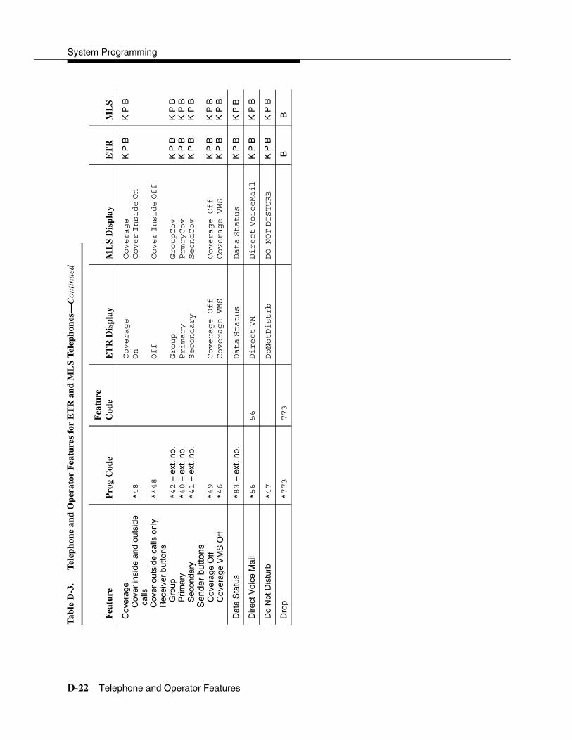
System Programming
D-22 Telephone and Operator Features
Cov
erag
eC
over
insi
de a
nd o
utsi
de
calls
Cov
er o
utsi
de c
alls
onl
yR
ecei
ver
butto
nsG
roup
Prim
ary
Sec
onda
ryS
ende
r bu
ttons
Cov
erag
e O
ffC
over
age
VM
S O
ff
*48
**48
*42
+ e
xt. n
o.*40
+ e
xt. n
o.*41
+ e
xt. n
o.
*49
*46
Coverage
On
Off
Group
Primary
Secondary
Coverage Off
Coverage VMS
Coverage
Cover
Inside
On
Cover
Inside
Off
GroupCov
PrmryCov
SecndCov
Coverage Off
Coverage VMS
K P
B
K P
BK
P B
K P
B
K P
BK
P B
K P
B
K P
BK
P B
K P
B
K P
BK
P B
Dat
a S
tatu
s*83
+ e
xt. n
o.Data
Status
Data
Status
K
P B
K P
B
Dire
ct V
oice
Mai
l*56
56
Direct
VM
Direct
VoiceMail
K
P B
K P
B
Do
Not
Dis
turb
*47
DoNotDistrb
DO NOT
DISTURB
K P
BK
P B
Dro
p*773
773
B B
Tab
le D
-3.
Tel
epho
ne a
nd O
pera
tor
Fea
ture
s fo
r E
TR
and
ML
S T
elep
hone
s—C
onti
nued
Fea
ture
Pro
g C
ode
Fea
ture
C
ode
ET
R D
ispl
ayM
LS
Dis
play
ET
RM
LS

General Feature Use and Telephone Programming
Telephone and Operator Features D-23
For
war
d an
d F
ollo
w M
eA
ctiv
ate
For
war
d (in
side
) R
emot
e C
all F
orw
ard
(out
side
) C
entr
ex T
rans
fer
via
Rem
ote
Cal
l For
war
d
Fol
low
Me
Can
cel
Can
cel s
endi
ng fr
om
your
tele
phon
e C
ance
l sen
ding
from
on
e ex
tens
ion
Can
cel s
endi
ng fr
om a
ll ex
tens
ions
*33
*33
*33
+ d
ial-o
ut
code
or *
+
optio
nal P
ause
s +
te
l. no
. + #
33
+ e
xt. n
o.33
+ te
l no.
34
+ e
xt. n
o.
33
+ y
our
ext.
no.
*34
+ e
xt.
no.
*34*
Forward
Forward
Forward
Forward
K P
BK
P B
Gro
up C
allin
gln
-Que
ue A
larm
but
ton
Cal
ling
grou
p m
embe
rsS
ign
in (
Ava
ilabl
e)
Sig
n ou
t (U
nava
ilabl
e)A
fter-
call
wor
k st
ate
(CM
S o
nly)
*22
+ c
allin
g gr
oup
ext.
no.
*44
*45
44
*44
45
Group
Call
ES2
ES1
Group
Call
ES2
ES1
K P
B
K P
BK
P B
K P
B
K P
B
K P
BK
P B
K P
B
Gro
up P
age
Aut
o D
ial B
utto
n*22
+ p
agin
g gr
oup
ext.
no.
Group
Page
Group
Page
K
P B
K P
B
Hol
dH
old
rele
ase
771
**
B B
B B
Tab
le D
-3.
Tel
epho
ne a
nd O
pera
tor
Fea
ture
s fo
r E
TR
and
ML
S T
elep
hone
s—C
onti
nued
Fea
ture
Pro
g C
ode
Fea
ture
C
ode
ET
R D
ispl
ayM
LS
Dis
play
ET
RM
LS

System Programming
D-24 Telephone and Operator Features
Inte
rcom
but
tons
Ass
ign
butto
ns2
ICO
M (
Def
ault
Rin
g)
ICO
M O
rigin
ate
Onl
y C
hang
e bu
tton
type
Rin
gV
oice
*16
*18
**19
*19
SysAccess
SysAcc-00
Place;
Ring
Place;
Voice
SysAccess
SysAcc-00
Place
Ring
Calls
Place
Voice
Calls
K P
BK
P B
Lang
uage
Cho
ice
Eng
lish
Fre
nch
Spa
nish
790
791
792
K P
BK
P B
Last
Num
ber
Dia
l *84
84
LastNumDial
Last
Number
Dial
K
P B
K P
B
Mes
sagi
ngLe
ave
Mes
sage
Afte
r ca
lling
With
out c
allin
gC
ance
l msg
. lef
tM
essa
ge L
ED
off
(non
-di
spla
y te
leph
ones
)M
essa
ge o
pera
tion
mod
e (d
ispl
ay te
leph
ones
)3
Pos
ted
Mes
sage
Rec
eivi
ng m
essa
ges
Del
ete
Mes
sage
4
Nex
t Mes
sage
4
Ret
urn
Cal
l4
Scr
oll4
*25
*54
*54
*751
*26
*28
*27
*29
25
53
+ e
xt n
o.*53
+ e
xt n
o.54
54
26
28
27
29
Msg
Leave
Msg
Lamp
Posted
Msg
Msg
Delete
Msg
Next
Msg
RtnCall
Msg
Scroll
Leave Message
Msg Leave
Message
Lamp
Posted
Message
Delete
Message
Next
Message
Message Return
call
Scroll Message
K P
BK
P B
K P
BK
P B
K P
B
K P
B
K P
B
K P
BK
P B
K P
B
K P
B
K P
BK
P B
K P
BK
P B
K P
B
K P
B
K P
B
K P
BK
P B
K P
B
K P
B
Tab
le D
-3.
Tel
epho
ne a
nd O
pera
tor
Fea
ture
s fo
r E
TR
and
ML
S T
elep
hone
s—C
onti
nued
Fea
ture
Pro
g C
ode
Fea
ture
C
ode
ET
R D
ispl
ayM
LS
Dis
play
ET
RM
LS
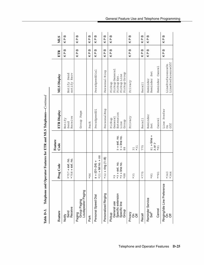
General Feature Use and Telephone Programming
Telephone and Operator Features D-25
Not
ify Sen
dR
ecei
ve*757
+ e
xt. n
o.*758
+ e
xt. n
o.
Notify
Send
Receive
Notify Send
notify Recv
K P
BK
P B
Pag
ing
Gro
up P
agin
gLo
udsp
eake
r P
agin
gGroup Page
K
P B
K P
B
Par
k*86
Park
K
P B
K P
B
Per
sona
l Spe
ed D
ial
# +
(01
–24)
+
*21
+ te
l no.
+ ##
PersSpeedDl
PersSpeedDial
K
P B
K P
B
Per
sona
lized
Rin
ging
*32
+ r
ing
(1–8
)PersonalRng
Personal
Ring
K
P B
K P
B
Pic
kup
Gen
eral
use
Spe
cific
ext
ensi
onS
peci
fic li
neG
roup
*9
*9
+ e
xt. n
o.*9
+ li
ne n
o.*88
9 +
ext
. no.
9 +
line
no.
88
Pickup
General
Extension
Line
Group
Pickup
Pickup
General
Pickup
Ext.
Pickup
Line
Pickup
Group
K P
BK
P B
Priv
acy
On
Off
*31
31
*31
Privacy
Privacy
K
P B
K P
B
Rec
all
*775
775
Recall
Recall
K
P B
K P
B
Rem
inde
r S
ervi
ceS
et5
Can
cel
*81
**81
81
+ ti
me
+
A o
r P
*81
Reminder
Set
Cancel
Reminder
Reminder Set
Reminder Cancel
K P
BK
P B
Rin
ging
/Idle
Lin
e P
refe
renc
eO
nO
ff*343
*344
Line Prefer
On
Off
LinePreferenceOn
LinePreferenceOff
K P
BK
P B
Tab
le D
-3.
Tel
epho
ne a
nd O
pera
tor
Fea
ture
s fo
r E
TR
and
ML
S T
elep
hone
s—C
onti
nued
Fea
ture
Pro
g C
ode
Fea
ture
C
ode
ET
R D
ispl
ayM
LS
Dis
play
ET
RM
LS
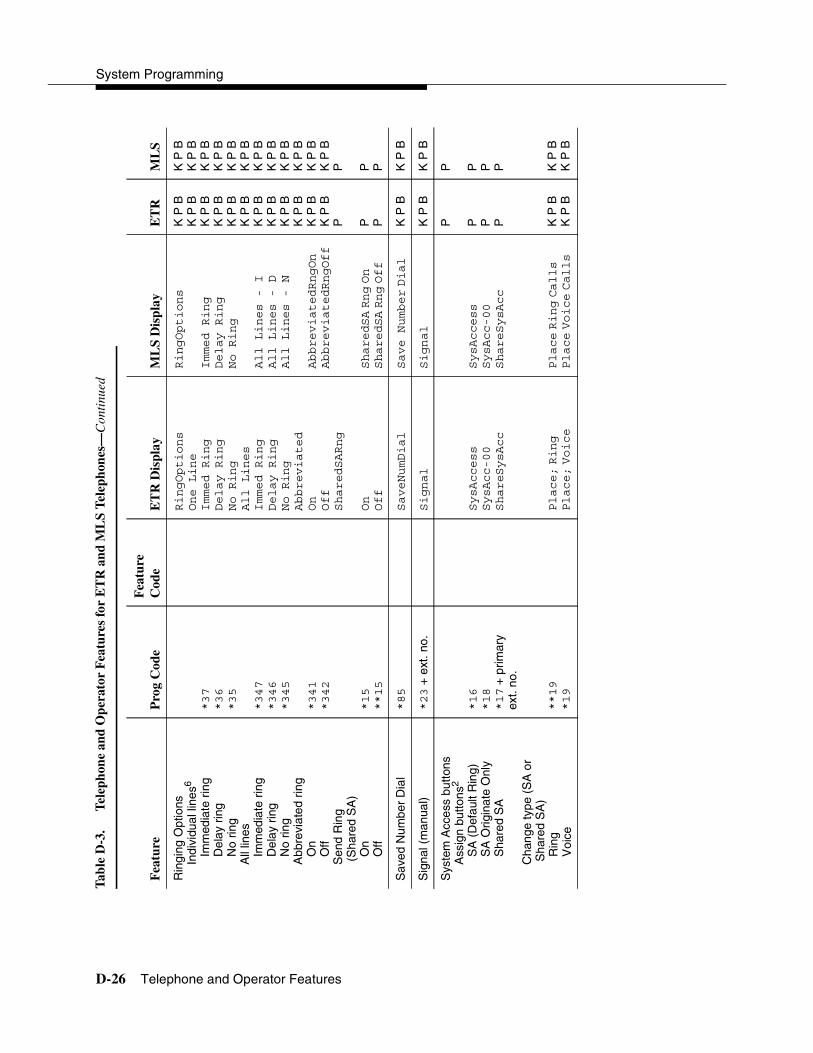
System Programming
D-26 Telephone and Operator Features
Rin
ging
Opt
ions
Indi
vidu
al li
nes6
Imm
edia
te r
ing
Del
ay r
ing
No
ring
All
lines
Imm
edia
te r
ing
Del
ay r
ing
No
ring
Abb
revi
ated
rin
gO
nO
ffS
end
Rin
g (S
hare
d S
A)
On
Off
*37
*36
*35
*347
*346
*345
*341
*342
*15
**15
RingOptions
One Line
Immed Ring
Delay Ring
No Ring
All Lines
Immed Ring
Delay Ring
No Ring
Abbreviated
On
Off
SharedSARng
On
Off
RingOptions
Immed Ring
Delay Ring
No Ring
All Lines - I
All Lines - D
All Lines - N
AbbreviatedRngOn
AbbreviatedRngOff
SharedSA
Rng
On
SharedSA
Rng
Off
K P
BK
P B
K P
BK
P B
K P
BK
P B
K P
BK
P B
K P
BK
P B
K P
BK
P B
P P P
K P
BK
P B
K P
BK
P B
K P
BK
P B
K P
BK
P B
K P
BK
P B
K P
BK
P B
P P P
Sav
ed N
umbe
r D
ial
*85
SaveNumDial
Save Number
Dial
K
P B
K P
B
Sig
nal (
man
ual)
*23
+ e
xt. n
o.Signal
Signal
K
P B
K P
B
Sys
tem
Acc
ess
butto
nsA
ssig
n bu
ttons
2
SA
(D
efau
lt R
ing)
S
A O
rigin
ate
Onl
yS
hare
d S
A
Cha
nge
type
(S
A o
r S
hare
d S
A)
Rin
g V
oice
*16
*18
*17
+ p
rimar
y ex
t. no
.
**19
*19
SysAccess
SysAcc-00
ShareSysAcc
Place;
Ring
Place;
Voice
SysAccess
SysAcc-00
ShareSysAcc
Place
Ring
Calls
Place
Voice
Calls
P P P P K P
BK
P B
P P P P K P
BK
P B
Tab
le D
-3.
Tel
epho
ne a
nd O
pera
tor
Fea
ture
s fo
r E
TR
and
ML
S T
elep
hone
s—C
onti
nued
Fea
ture
Pro
g C
ode
Fea
ture
C
ode
ET
R D
ispl
ayM
LS
Dis
play
ET
RM
LS

General Feature Use and Telephone Programming
Telephone and Operator Features D-27
Sys
tem
Spe
ed D
ial
*24
+ c
ode
( 600-729
)600-729
SysSpeedDl
SysSpeedDial
K
P B
K
P B
Tra
nsfe
r *774
774
Trans
B
B
Voi
ce A
nnou
nce
On
Off
*10
**10
Voice Annce
Receive; On
Receive;
Off
Voice Annce
RecvVoiceAnn On
RecvVoiceAnn Off
K P
BK
P B
1C
entr
aliz
ed te
leph
one
prog
ram
min
g on
ly.
2P
ress
the
* bu
tton
and
use
the
volu
me
up a
nd d
own
key;
for
ET
R te
leph
ones
onl
y.
3F
or M
LS a
nd E
TR
dis
play
tele
phon
e us
ers,
pre
ssin
g *54
ent
ers/
exits
Mes
sage
ope
ratio
n m
ode.
MLS
tele
phon
es r
etur
n to
nor
mal
cal
l han
dlin
g af
ter
15
seco
nds
if th
e us
er h
as n
o m
essa
ges.
If a
n M
LS te
leph
one
user
has
mes
sage
s, h
e or
she
mus
t del
ete
the
mes
sage
s or
use
the
feat
ure
code
or
prog
ram
med
bu
tton
to e
xit M
essa
ge o
pera
tion.
An
ET
R te
leph
one
user
mus
t use
the
feat
ure
code
or
the
prog
ram
med
but
ton
to e
xit M
essa
ge o
pera
tion
whe
ther
or
not h
e or
she
has
mes
sage
s.
4D
ispl
ay te
leph
ones
onl
y. P
rogr
amm
ing
and
feat
ure
code
s ar
e us
ed w
ith a
nalo
g m
ultil
ine,
ET
R, a
nd M
LS te
leph
ones
.
5E
nglis
h on
ly: t
ime
is 1
2-ho
ur (
0100
–125
9) +
2 (
A)
or 7
(P
). F
renc
h an
d S
pani
sh: t
ime
is 2
4-ho
ur (
0000
–235
9).
6W
ith Im
med
iate
Rin
g (s
tead
y re
d LE
D),
inco
min
g ca
lls a
re im
med
iate
ly d
eliv
ered
. With
Del
ay R
ing
(slo
w r
ed L
ED
), in
com
ing
calls
are
del
ayed
(de
faul
t is
2 rin
gs).
With
No
Rin
g (L
ED
off)
, no
calls
are
del
iver
ed.
Tab
le D
-3.
Tel
epho
ne a
nd O
pera
tor
Fea
ture
s fo
r E
TR
and
ML
S T
elep
hone
s—C
onti
nued
Fea
ture
Pro
g C
ode
Fea
ture
C
ode
ET
R D
ispl
ayM
LS
Dis
play
ET
RM
LS

System Programming
D-28 Telephone Programming
Telephone Programming 4
The following describes how to program features on MLX, ETR, MLS, and analog multiline telephones. Because Personal Speed Dial is the only feature that single-line telephone users can program, general programming instructions for single-line telephones are not provided.
NOTE:Features cannot be programmed on QCCs in system operator positions.
Features assigned to these consoles are fixed and cannot be changed.
Programming Methods 4
Telephones can be programmed by dialing programming codes or, on MLX display telephones, by selecting features from the display. Analog multiline, ETR, and MLS telephones cannot be programmed by selecting features from the display.
To program a telephone, first enter programming mode:
� On analog multiline telephones, slide the Test/Program (T/P) switch on the side of the telephone to P, or lift the handset, or press the Spkrphone button and dial #00.
� On ETR and MLS telephones, press the Feature button and dial 00.
� On MLX-10 and MLX-5 nondisplay telephones, press the Feature button and dial 00.
� On MLX display telephones, use the same procedures as for the MLX nondisplay telephones or enter programming mode by selecting Ext Program from the menu screen on the display.
� On TransTalk MDC 9000 and MDW 9000 telephones, press the imprinted Feat button and dial 00.
� On Business Cordles 905, press SHIFT + PROG.
See the appropriate user or operator guide for more information.
NOTE:Features can also be programmed onto individual telephones through centralized telephone programming. The steps for using programming codes vary, depending on the telephone. Tables D-4 through D-8 list the basic steps for programming each telephone type.
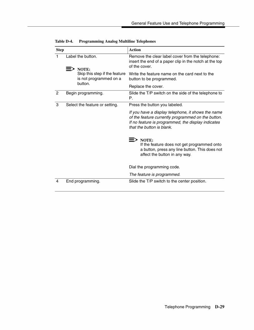
General Feature Use and Telephone Programming
Telephone Programming D-29
Table D-4. Programming Analog Multiline Telephones
Step Action
1 Label the button.
NOTE:Skip this step if the feature is not programmed on a button.
Remove the clear label cover from the telephone: insert the end of a paper clip in the notch at the top of the cover.
Write the feature name on the card next to the button to be programmed.
Replace the cover.
2 Begin programming. Slide the T/P switch on the side of the telephone to P.
3 Select the feature or setting. Press the button you labeled.
If you have a display telephone, it shows the name of the feature currently programmed on the button. If no feature is programmed, the display indicates that the button is blank.
NOTE:If the feature does not get programmed onto a button, press any line button. This does not affect the button in any way.
Dial the programming code.
The feature is programmed.
4 End programming. Slide the T/P switch to the center position.

System Programming
D-30 Telephone Programming
Table D-5. Programming ETR and MLS Telephones
Step Action
1 Label the button.
NOTE:Skip this step if the feature is not programmed on a button.
Remove the clear label cover from the telephone: pull up on the tab that extends from the top of the cover.
Write the feature name on the card next to the button to be programmed.
Replace the cover.
2 Begin programming. Press the Feature button, and then dial 00.
3 Select the feature or setting. Press the button you labeled.
NOTE:If the feature is programmed onto a button, press any line button. This does not affect the button in any way.
Dial the programming code.
The feature is programmed.
4 End programming. Press the Feature button, and dial *00.
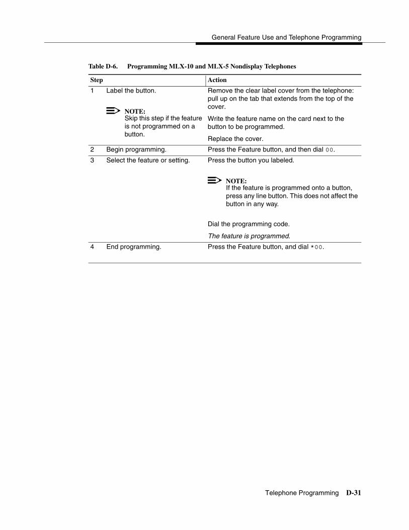
General Feature Use and Telephone Programming
Telephone Programming D-31
Table D-6. Programming MLX-10 and MLX-5 Nondisplay Telephones
Step Action
1 Label the button.
NOTE:Skip this step if the feature is not programmed on a button.
Remove the clear label cover from the telephone: pull up on the tab that extends from the top of the cover.
Write the feature name on the card next to the button to be programmed.
Replace the cover.
2 Begin programming. Press the Feature button, and then dial 00.
3 Select the feature or setting. Press the button you labeled.
NOTE:If the feature is programmed onto a button, press any line button. This does not affect the button in any way.
Dial the programming code.
The feature is programmed.
4 End programming. Press the Feature button, and dial *00.
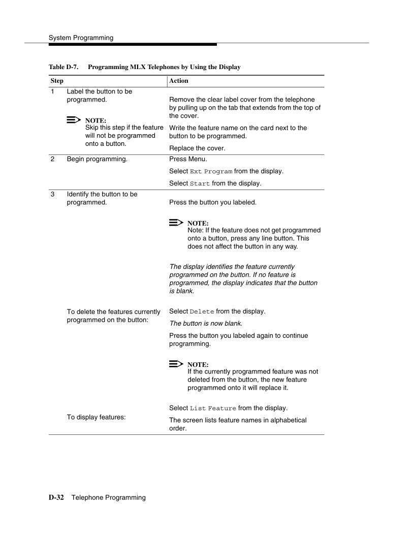
System Programming
D-32 Telephone Programming
Table D-7. Programming MLX Telephones by Using the Display
Step Action
1 Label the button to be programmed.
NOTE:Skip this step if the feature will not be programmed onto a button.
Remove the clear label cover from the telephone by pulling up on the tab that extends from the top of the cover.
Write the feature name on the card next to the button to be programmed.
Replace the cover.
2 Begin programming. Press Menu.
Select Ext Program from the display.
Select Start from the display.
3 Identify the button to be programmed.
To delete the features currently programmed on the button:
To display features:
Press the button you labeled.
NOTE:Note: If the feature does not get programmed onto a button, press any line button. This does not affect the button in any way.
The display identifies the feature currently programmed on the button. If no feature is programmed, the display indicates that the button is blank.
Select Delete from the display.
The button is now blank.
Press the button you labeled again to continue programming.
NOTE:If the currently programmed feature was not deleted from the button, the new feature programmed onto it will replace it.
Select List Feature from the display.
The screen lists feature names in alphabetical order.
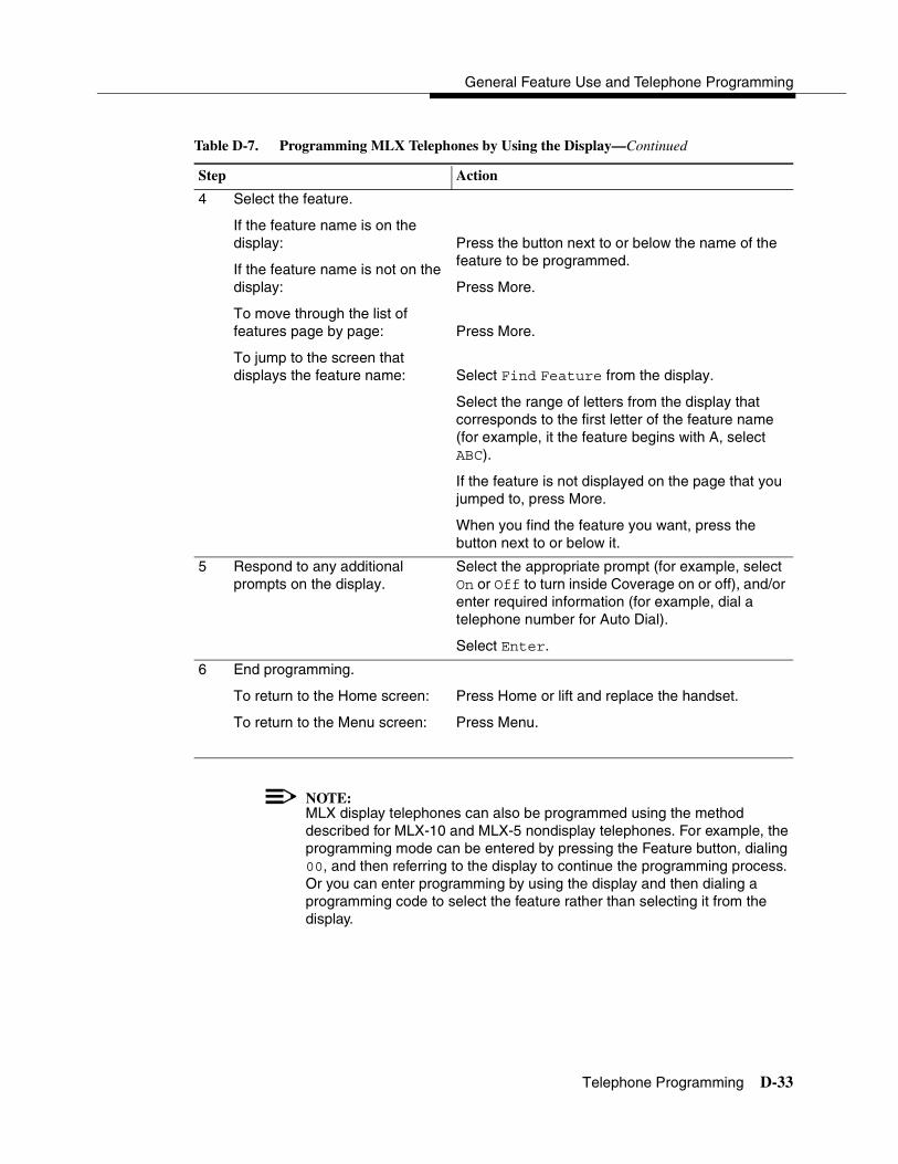
General Feature Use and Telephone Programming
Telephone Programming D-33
NOTE:MLX display telephones can also be programmed using the method described for MLX-10 and MLX-5 nondisplay telephones. For example, the programming mode can be entered by pressing the Feature button, dialing 00, and then referring to the display to continue the programming process. Or you can enter programming by using the display and then dialing a programming code to select the feature rather than selecting it from the display.
4 Select the feature.
If the feature name is on the display:
If the feature name is not on the display:
To move through the list offeatures page by page:
To jump to the screen that displays the feature name:
Press the button next to or below the name of the feature to be programmed.
Press More.
Press More.
Select Find Feature from the display.
Select the range of letters from the display that corresponds to the first letter of the feature name (for example, it the feature begins with A, select ABC).
If the feature is not displayed on the page that you jumped to, press More.
When you find the feature you want, press the button next to or below it.
5 Respond to any additional prompts on the display.
Select the appropriate prompt (for example, select On or Off to turn inside Coverage on or off), and/or enter required information (for example, dial a telephone number for Auto Dial).
Select Enter.
6 End programming.
To return to the Home screen:
To return to the Menu screen:
Press Home or lift and replace the handset.
Press Menu.
Table D-7. Programming MLX Telephones by Using the Display—Continued
Step Action
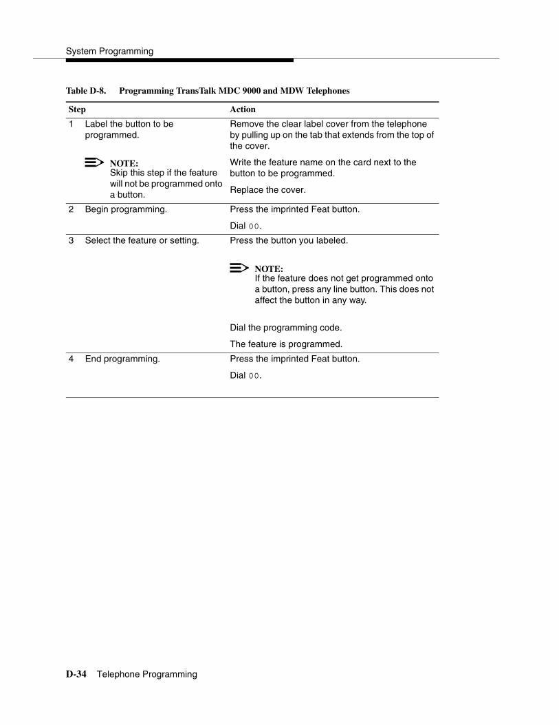
System Programming
D-34 Telephone Programming
Table D-8. Programming TransTalk MDC 9000 and MDW Telephones
Step Action
1 Label the button to beprogrammed.
NOTE:Skip this step if the feature will not be programmed onto a button.
Remove the clear label cover from the telephone by pulling up on the tab that extends from the top of the cover.
Write the feature name on the card next to the button to be programmed.
Replace the cover.
2 Begin programming. Press the imprinted Feat button.
Dial 00.
3 Select the feature or setting. Press the button you labeled.
NOTE:If the feature does not get programmed onto a button, press any line button. This does not affect the button in any way.
Dial the programming code.
The feature is programmed.
4 End programming. Press the imprinted Feat button.
Dial 00.

Overview E-1
E����������� E
�������� 4
This appendix contains the button diagrams for Hybrid/PBX, Key, and Behind Switch systems.
Figure E-1. MLX-20L and MLX-28D Telephone (Hybrid/PBX Mode)
28
20
27
26
25
24
23
22
21
20
19
18
17
16
15
28
10
9
8
7
14
13
12
116
5
4
3
2
1 SA Ring
SA Ring
3 8
2 7
1 6
4
5
13
12
11
10
9
18
17
16
15
14
SA Orig. Only
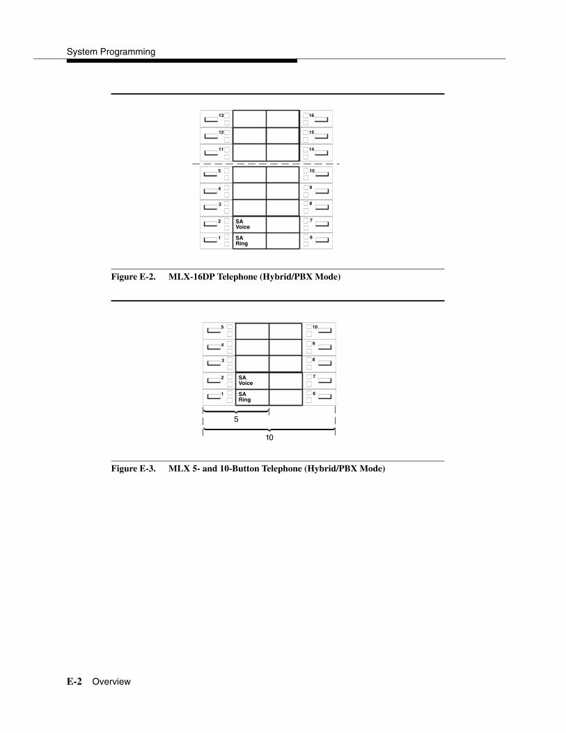
System Programming
E-2 Overview
Figure E-2. MLX-16DP Telephone (Hybrid/PBX Mode)
Figure E-3. MLX 5- and 10-Button Telephone (Hybrid/PBX Mode)
15
14
12
11
SA Voice
SARing
10
9
8
7
6
5
4
3
2
1
1613
SAVoice
SARing
10
9
8
7
6
5
4
3
2
1
5
10

Button Diagrams
Overview E-3
Figure E-4. Analog Multiline Telephone (Hybrid/PBX Mode)
24
23
22
21
19
20
18
17
16
14
15
13
12
11
22 BUTTON
5 BUTTON
10 BUTTON
SARing
SAVoice
SAOrig Only
30
31
32
33
34
1
2
3
4
5
29
25
26
27
28
6
7
8
9
10

System Programming
E-4 Overview
Figure E-5. MLX-20L and MLX-28D Telephone (Key and Behind Switch Modes)
Figure E-6. MLX-16DP Telephone (Key and Behind Switch Modes)
28
20
27
26
25
24
23
22
21
20
19
18
17
16
15
28
Icom Voice
Icom Ring
10
9
8
7
14
13
12
116
5
4
3
2
1
10
Key Mode:Up to 8 personal linebuttons are assignedbeginning at button 3.
Behind Switch Mode:One prime line buttonis assigned to button 3.
15
14
12
11
Icom Voice
IcomRing
10
9
8
7
6
5
4
3
2
1
1613
Key Mode:Up to 8 personal linebuttons are assignedbeginning at button 3.
Behind Switch Mode:One prime line buttonis assigned to button 3.
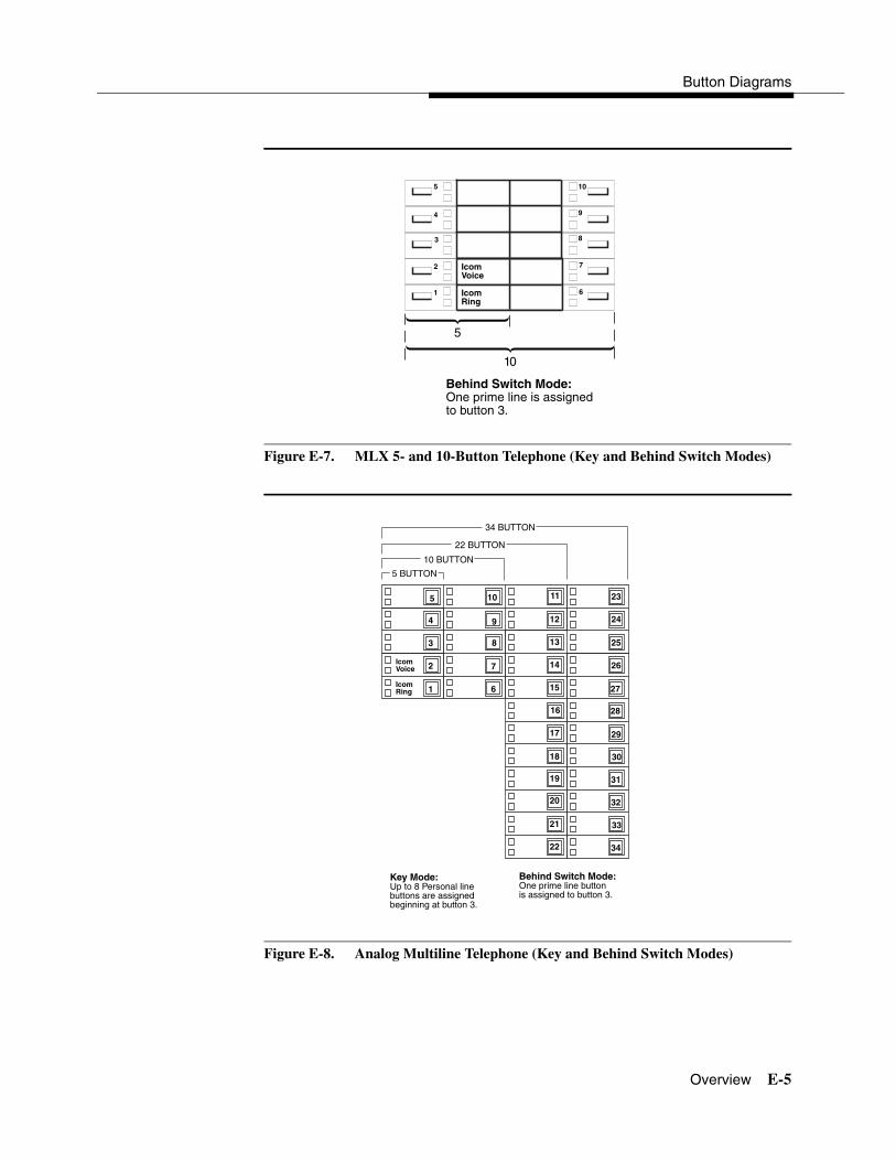
Button Diagrams
Overview E-5
Figure E-7. MLX 5- and 10-Button Telephone (Key and Behind Switch Modes)
Figure E-8. Analog Multiline Telephone (Key and Behind Switch Modes)
IcomVoice
IcomRing
10
9
8
7
6
5
4
3
2
1
5
10
Behind Switch Mode:One prime line is assigned to button 3.
24
23
22
21
19
20
18
17
16
14
15
13
12
11
22 BUTTON
34 BUTTON
5 BUTTON
10 BUTTON
IcomRing
IcomVoice
30
31
32
33
34
1
2
3
4
5
29
25
26
27
28
6
7
8
9
10
Key Mode:Up to 8 Personal linebuttons are assignedbeginning at button 3.
Behind Switch Mode:One prime line buttonis assigned to button 3.
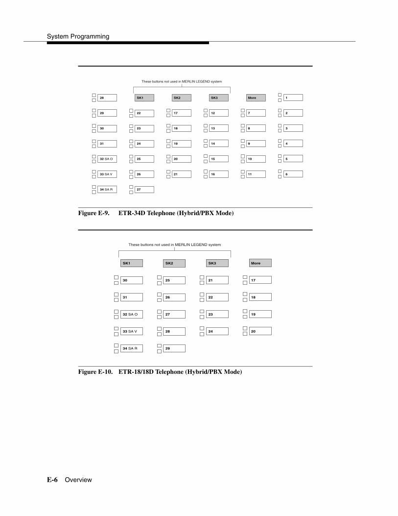
System Programming
E-6 Overview
Figure E-9. ETR-34D Telephone (Hybrid/PBX Mode)
Figure E-10. ETR-18/18D Telephone (Hybrid/PBX Mode)
SK1
22
23
24
25
26
27
28
29
30
31
32 SA O
33 SA V
34 SA R
SK2
17
18
19
20
21
SK3
12
13
14
15
16
More
7
8
9
10
11
1
2
3
4
5
6
These buttons not used in MERLIN LEGEND system
SK1
30
31
32 SA O
33 SA V
34 SA R
SK2
25
26
27
28
29
SK3
21
22
23
24
More
17
18
19
20
These buttons not used in MERLIN LEGEND system

Button Diagrams
Overview E-7
Figure E-11. ETR-6 Telephone (Hybrid/PBX Mode)
Figure E-12. MLS-34D Telephone (Hybrid/PBX Mode)
29
30
31
32 SA O
33 SA V
34 SA R
23
24
25
26
27
28
29
30
31
32 SA O
33 SA V
34 SA R
17
18
19
20
21
22
11
12
13
14
15
16
6
7
8
9
10
1
2
3
4
5
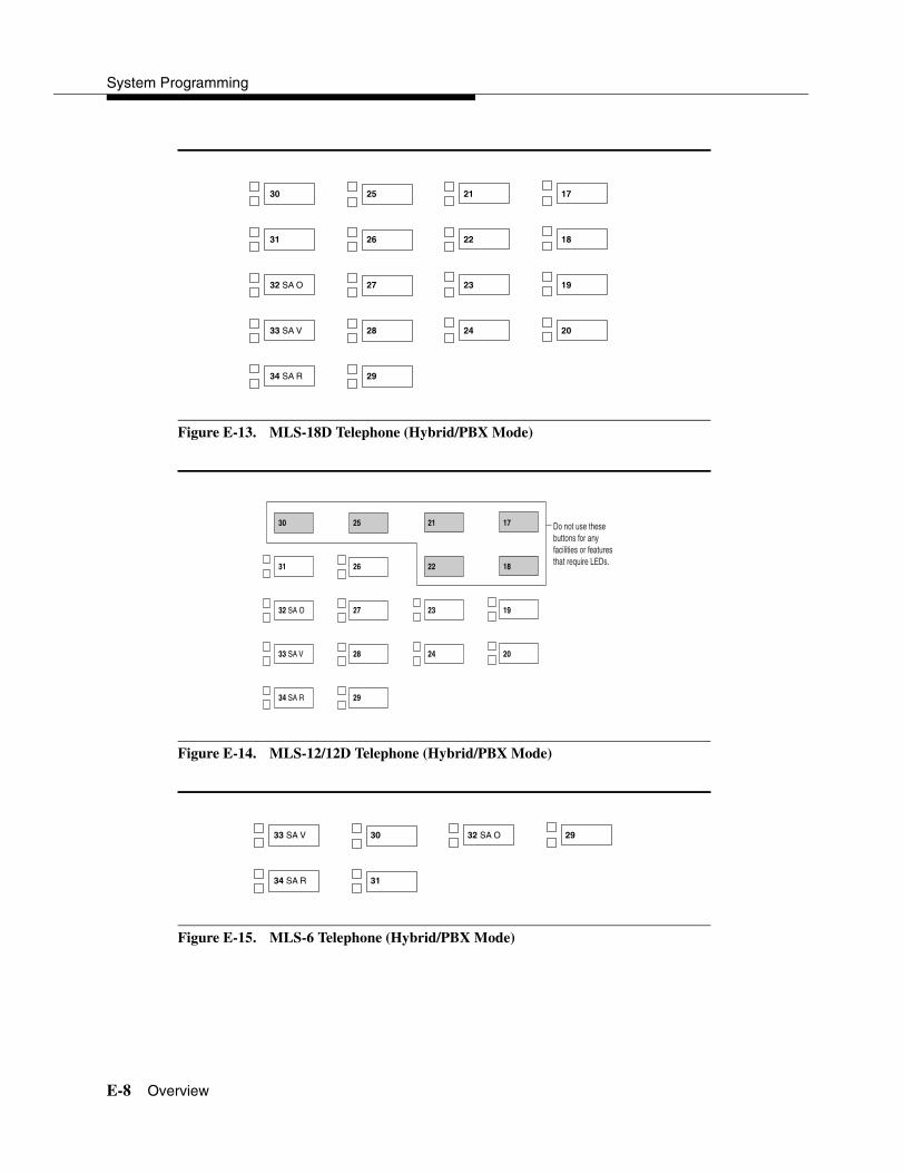
System Programming
E-8 Overview
Figure E-13. MLS-18D Telephone (Hybrid/PBX Mode)
Figure E-14. MLS-12/12D Telephone (Hybrid/PBX Mode)
Figure E-15. MLS-6 Telephone (Hybrid/PBX Mode)
25
26
27
28
29
30
31
32 SA O
33 SA V
34 SA R
21
22
23
24
17
18
19
20
25
26
27
28
29
30
31
32 SA O
33 SA V
34 SA R
21
22
23
24
17
18
19
20
Do not use these buttons for any facilities or features that require LEDs.
30
31
33 SA V
34 SA R
32 SA O 29
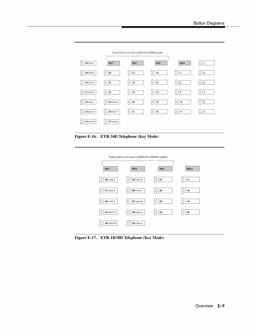
Button Diagrams
Overview E-9
Figure E-16. ETR-34D Telephone (Key Mode)
Figure E-17. ETR-18/18D Telephone (Key Mode)
SK1
22
23
24
25 Line 8
26 Line 7
27 Line 6
28 Line 5
29 Line 4
30 Line 3
31 Line 2
32 Line 1
33 Icom V
34 Icom R
SK2
17
18
19
20
21
SK3
12
13
14
15
16
More
7
8
9
10
11
1
2
3
4
5
6
These buttons not used in MERLIN LEGEND system
SK1
30 Line 3
31 Line 2
32 Line 1
33 Icom V
34 Icom R
SK2
25 Line 8
26 Line 7
27 Line 6
28 Line 5
29 Line 4
SK3
21
22
23
24
More
17
18
19
20
These buttons not used in MERLIN LEGEND system

System Programming
E-10 Overview
Figure E-18. ETR-6 Telephone (Key Mode)
Figure E-19. MLS-34D Telephone (Key Mode)
32 Line 1
33 Icom V
34 Icom R
30 Line 3
31 Line 2
29
23
24
25 Line 8
26 Line 7
27 Line 6
28 Line 5
29 Line 4
30 Line 3
31 Line 2
32 Line 1
33 Icom V
34 Icom R
17
18
19
20
21
22
11
12
13
14
15
16
6
7
8
9
10
1
2
3
4
5
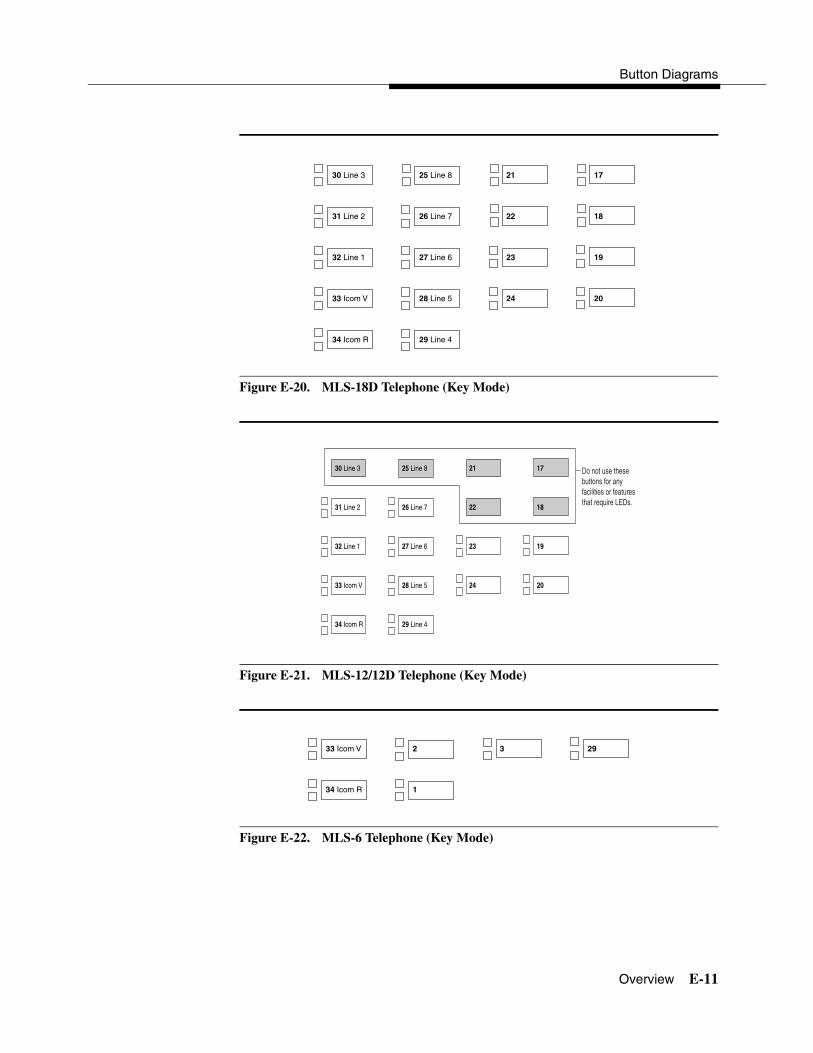
Button Diagrams
Overview E-11
Figure E-20. MLS-18D Telephone (Key Mode)
Figure E-21. MLS-12/12D Telephone (Key Mode)
Figure E-22. MLS-6 Telephone (Key Mode)
25 Line 8
26 Line 7
27 Line 6
28 Line 5
29 Line 4
30 Line 3
31 Line 2
32 Line 1
33 Icom V
34 Icom R
21
22
23
24
17
18
19
20
25 Line 8
26 Line 7
27 Line 6
28 Line 5
29 Line 4
30 Line 3
31 Line 2
32 Line 1
33 Icom V
34 Icom R
21
22
23
24
17
18
19
20
Do not use these buttons for any facilities or features that require LEDs.
2
1
33 Icom V
34 Icom R
3 29

System Programming
E-12 Overview
Figure E-23. ETR-34D Telephone (Behind Switch Mode)
Figure E-24. ETR-18/18D Telephone (Behind Switch Mode)
SK1
22
23
24
25
26
27
28
29
30
31
32 Prime
33 Icom V
34 Icom R
SK2
17
18
19
20
21
SK3
12
13
14
15
16
More
7
8
9
10
11
1
2
3
4
5
6
These buttons not used in MERLIN LEGEND system
SK1
30
31
32 Prime
33 Icom V
34 Icom R
SK2
25
26
27
28
29
SK3
21
22
23
24
More
17
18
19
20
These buttons not used in MERLIN LEGEND system
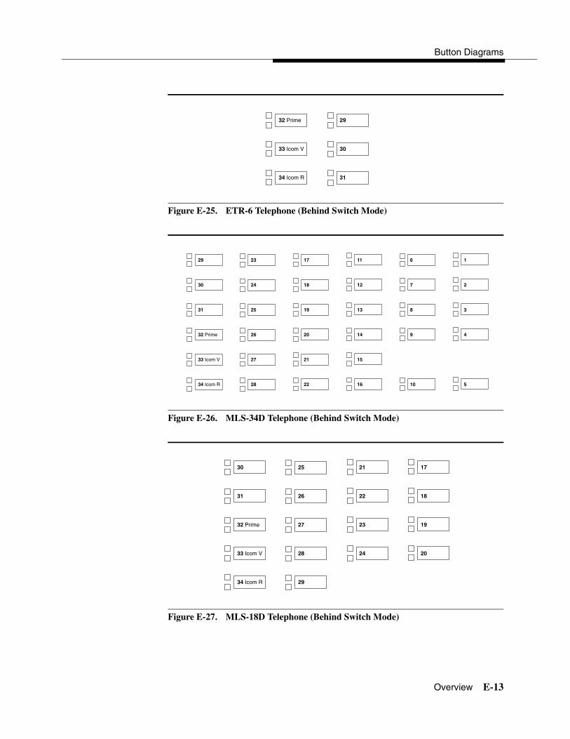
Button Diagrams
Overview E-13
Figure E-25. ETR-6 Telephone (Behind Switch Mode)
Figure E-26. MLS-34D Telephone (Behind Switch Mode)
Figure E-27. MLS-18D Telephone (Behind Switch Mode)
29
30
31
32 Prime
33 Icom V
34 Icom R
23
24
25
26
27
28
29
30
31
32 Prime
33 Icom V
34 Icom R
17
18
19
20
21
22
11
12
13
14
15
16
6
7
8
9
10
1
2
3
4
5
25
26
27
28
29
30
31
32 Prime
33 Icom V
34 Icom R
21
22
23
24
17
18
19
20

System Programming
E-14 Overview
Figure E-28. MLS-12/12D Telephone (Behind Switch Mode)
Figure E-29. MLS-6 Telephone (Behind Switch Mode)
25
26
27
28
29
30
31
32 Prime
33 Icom V
34 Icom R
21
22
23
24
17
18
19
20
Do not use these buttons for any facilities or features that require LEDs.
30
31
33 Icom V
34 Icom R
32 Prime 29

Overview F-1
F������������� F
������ 4
This appendix includes samples of the print reports generated by the communications system. Table F-1 lists the system reports and the pages in this appendix where samples can be found.
NOTE:The system’s Station Message Detail Recording (SMDR) feature reports incoming and outgoing call details.
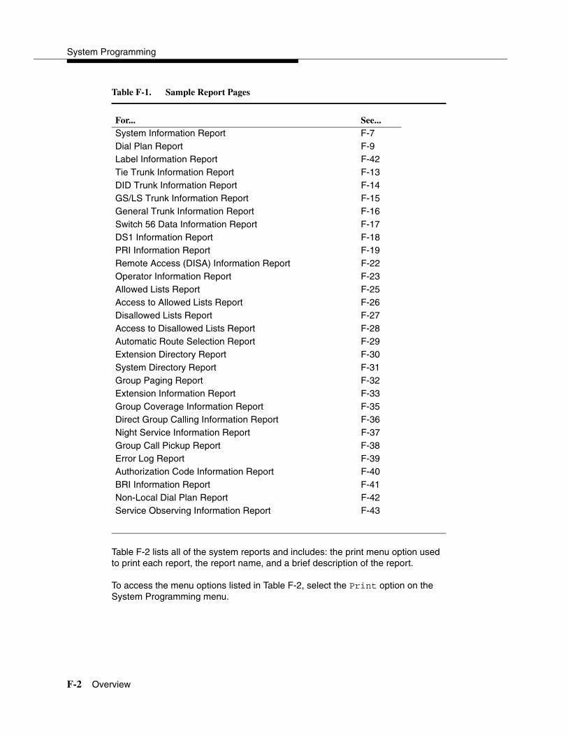
System Programming
F-2 Overview
Table F-1. Sample Report Pages
Table F-2 lists all of the system reports and includes: the print menu option used to print each report, the report name, and a brief description of the report.
To access the menu options listed in Table F-2, select the Print option on the System Programming menu.
For... See...System Information Report F-7Dial Plan Report F-9Label Information Report F-42Tie Trunk Information Report F-13DID Trunk Information Report F-14GS/LS Trunk Information Report F-15General Trunk Information Report F-16Switch 56 Data Information Report F-17DS1 Information Report F-18PRI Information Report F-19Remote Access (DISA) Information Report F-22Operator Information Report F-23Allowed Lists Report F-25Access to Allowed Lists Report F-26Disallowed Lists Report F-27Access to Disallowed Lists Report F-28Automatic Route Selection Report F-29Extension Directory Report F-30System Directory Report F-31Group Paging Report F-32Extension Information Report F-33Group Coverage Information Report F-35Direct Group Calling Information Report F-36Night Service Information Report F-37Group Call Pickup Report F-38Error Log Report F-39Authorization Code Information Report F-40BRI Information Report F-41Non-Local Dial Plan Report F-42Service Observing Information Report F-43

Sample Reports
Overview F-3
Table F-2. System Reports
Menu Option Report Name Description
All Prints each of the reports available on the Print menu, from SysSet-up to Error Log.
NOTE: With All selected, four trunk information reports automatically print. See Trunk Info.
SysSet-up System Information Systemwide information such as return intervals, system mode, system programming port, slot assignments, and so on.
Dial Plan Dial Plan Extensions assigned to pools, paging zones, calling groups, lines or trunks, and stations (in the report); labels for lines/trunks and stations.
Labels Label Information Labels assigned to stations (extensions), Posted Messages, and names and telephone numbers in MLX-20L Personal Directory.
Trunk Info Select to display four trunk options: Tie, DID, Loop/Ground, General.
TIE TIE Trunk Information Extensions assigned to, and signaling attributes associated with, Tie trunks.
DID DID Trunk Information Extensions assigned to, and signaling attributes associated with, DID trunks.
Loop/Ground
GS/LS Trunk Information
Extensions assigned to, and signaling attributes for, ground- and loop-start lines/trunks.
General General Trunk Information
All identified extensions and feature-related attributes of each extension.
S56 Data Switch 56 Data Information Report
Dial Plan Routing information and programmable options.
T1 Info DS1 information Options (line, signal, and so on) assigned to T1 trunks or lines.
PRI Info PRI Information PRI trunks assigned to B-channel groups.
RmoteAccess Remote Access (DISA) Information
Remote access dial code, class of restriction, barrier code information.

System Programming
F-4 Overview
Oper Info Operator Information For each system operator position: logical ID, extension number, label, type (DLC or QCC). All general system operator options, such as backup position; call types and priorities.
AllowList Allowed Lists Telephone numbers included in Allowed Lists. Lists numbered 0–7; entries numbered 0–9.
AllowListTo Access to Allowed Lists Lists numbered 0–7. If the Allowed List is assigned to remote access users and barrier codes are used, barrier codes are numbered 0–16. If no barrier codes are used, 17 means list is assigned to tie-trunk users and 18 means list is assigned to non-tie-trunk users.
DisallowLst Disallowed Lists Telephone numbers included in Disallowed Lists. Lists are numbered 0–7, and entries are numbered 0–9.
DisallowTo Access to Disallowed Lists
Telephones to which Disallowed Lists are assigned. Lists are numbered 0–7. If the Disallowed List is assigned to Remote Access users and barrier codes are used, the barrier codes are numbered 0–16. If no barrier codes are used, 17 means the Disallowed List is assigned to tie-trunk users and 18 means the Disallowed List is assigned to non-tie-trunk users.
ARS Automatic Route Selection
Access code; table types with area codes and exchanges; routes for subpatterns A and B, FRL, absorb digit, delete digit, Dial 0, and N11 tables.
Ext Direct Extension Directory Slot/port addresses, extensions, labels and feature-related attributes. Column headings are printed on the first page only and are not carried over to subsequent pages. Column headings 4 through 11 (and 15 through 22) should be read vertically—that is: FACE (Forced Account Code Entry); HBIS (HFAI/BIS); RCFW (Remote Call Forward); MICD (Microphone Disable); SIG (Voice Signal); RSTR (Calling Restrictions); ARSR (ARS Restriction Level); 2BDT (2B Data Capability).
Table F-2. System Reports—Continued
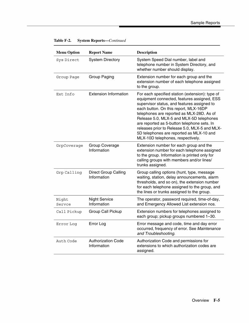
Sample Reports
Overview F-5
Menu Option Report Name Description
Sys Direct System Directory System Speed Dial number, label and telephone number in System Directory, and whether number should display.
Group Page Group Paging Extension number for each group and the extension number of each telephone assigned to the group.
Ext Info Extension Information For each specified station (extension): type of equipment connected, features assigned, ESS supervisor status, and features assigned to each button. On this report, MLX-16DP telephones are reported as MLX-28D. As of Release 5.0, MLX-5 and MLX-5D telephones are reported as 5-button telephone sets. In releases prior to Release 5.0, MLX-5 and MLX-5D telephones are reported as MLX-10 and MLX-10D telephones, respectively.
GrpCoverage Group CoverageInformation
Extension number for each group and the extension number for each telephone assigned to the group. Information is printed only for calling groups with members and/or lines/trunks assigned.
Grp Calling Direct Group Calling Information
Group calling options (hunt, type, message waiting, station, delay announcements, alarm thresholds, and so on), the extension number for each telephone assigned to the group, and the lines or trunks assigned to the group.
Night Servce
Night Service Information
The operator, password required, time-of-day, and Emergency Allowed List extension nos.
Call Pickup Group Call Pickup Extension numbers for telephones assigned to each group; pickup groups numbered 1–30.
Error Log Error Log Error message and code, time and day error occurred, frequency of error. See Maintenance and Troubleshooting.
Auth Code Authorization Code Information
Authorization Code and permissions for extensions to which authorization codes are assigned.
Table F-2. System Reports—Continued

System Programming
F-6 Overview
Menu Option Report Name Description
BRI Info BRI Information Service Profile ID and Directory Number for each BRI line, flexible timers, and fixed timers and counters.
NonLcl UDP Non-Local Dial Plan Ranges of extension numbers for non-local dial plan extensions connected to a networked external switch; pattern number associated with each range. For each pattern, shows Pool number, absorbed and prepended (other) digits, FRL, and call type (voice, data, or both).
ServiceObs Service Observing Information Report
Service Observing group information including: Group number, Observer number, and member information (extension and label).
Table F-2. System Reports—Continued
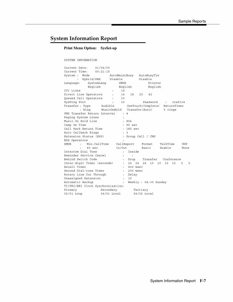
Sample Reports
System Information Report F-7
�������������������� 4
Print Menu Option: SysSet-up
SYSTEM INFORMATION
Current Date: 01/04/00Current Time: 00:21:15System : Mode AutoMaintBusy AutoBusyTie : Hybrid/PBX Disable DisableLanguage: SystemLang SMDR Printer English English EnglishCTI Links : 19 Direct Line Operators : 14 18 22 42Queued Call Operators : 10SysProg Port : 10 Password : craftr4Transfer : Type Audible OneTouch(Complete) ReturnTimer
: Ring MusicOnHold Transfer(Auto) 5 ringsVMS Transfer Return Interval : 4Paging System Lines :Music On Hold Line : 804Camp On Time : 90 secCall Park Return Time : 180 secAuto Callback Rings : 3Extension Status (ESS) : Group Call / CMSESS Operators :SMDR : Min.CallTime CallReport Format TalkTime UDP
: 40 sec In/Out Basic Enable NoneIntercom Dial Tone : InsideReminder Service Cancel : :Behind Switch Code : Drop Transfer ConferenceInter-digit Timer (seconds) : 24 24 24 10 10 10 10 5 5Recall Timer : 450 msecSecond Dial-tone Timer : 200 msecRotary Line Cut Through : DelayUnassigned Extension : 10Automatic Backup : Weekly - 04:30 SundayTI/PRI/BRI Clock Synchronization:Primary Secondary Tertiary02/01 Loop 04/01 Local 04/02 Local

System Programming
F-8 System Information Report
����������������������������� 4
Slot # 1: 008 MLXSlot # 2: 408Slot # 3: 008Slot # 4: 408Slot # 5: 800 GS/LSSlot # 6: 008 GS/LS-MLXSlot # 7: 800 CO-BRISlot # 8: 008Slot # 9: 016 (Ringing Frequency - 25 Hz.)Slot #10: 408 GS/LSSlot #11: 008Slot #12: 800Slot #13: 800 DIDSlot #14: 400 EMSlot #15: 012Slot #16: 008 MLXSlot #17: 408 * Not Present *
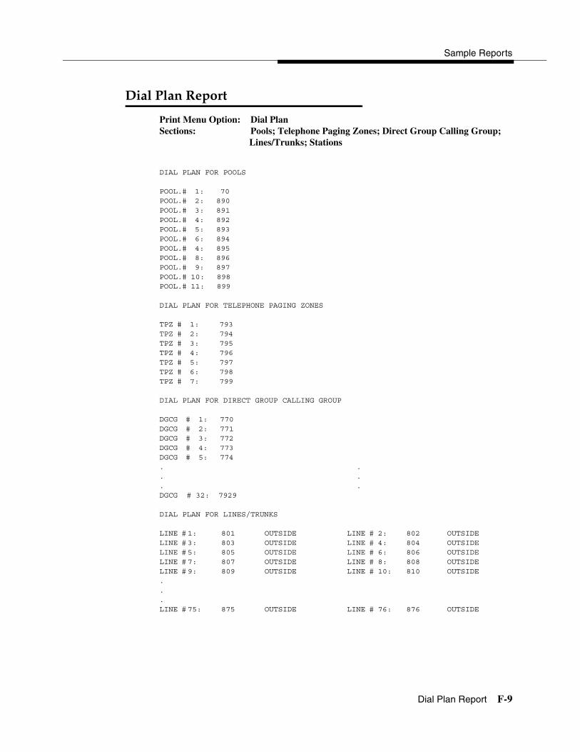
Sample Reports
Dial Plan Report F-9
�������������� 4
Print Menu Option: Dial PlanSections: Pools; Telephone Paging Zones; Direct Group Calling Group;
Lines/Trunks; Stations
DIAL PLAN FOR POOLS
POOL.# 1: 70POOL.# 2: 890POOL.# 3: 891POOL.# 4: 892POOL.# 5: 893POOL.# 6: 894POOL.# 4: 895POOL.# 8: 896POOL.# 9: 897POOL.# 10: 898POOL.# 11: 899
DIAL PLAN FOR TELEPHONE PAGING ZONES
TPZ # 1: 793TPZ # 2: 794TPZ # 3: 795TPZ # 4: 796TPZ # 5: 797TPZ # 6: 798TPZ # 7: 799
DIAL PLAN FOR DIRECT GROUP CALLING GROUP
DGCG # 1: 770DGCG # 2: 771DGCG # 3: 772DGCG # 4: 773DGCG # 5: 774. .. .. .DGCG # 32: 7929
DIAL PLAN FOR LINES/TRUNKS
LINE # 1: 801 OUTSIDE LINE # 2: 802 OUTSIDELINE # 3: 803 OUTSIDE LINE # 4: 804 OUTSIDELINE # 5: 805 OUTSIDE LINE # 6: 806 OUTSIDELINE # 7: 807 OUTSIDE LINE # 8: 808 OUTSIDELINE # 9: 809 OUTSIDE LINE # 10: 810 OUTSIDE...LINE # 75: 875 OUTSIDE LINE # 76: 876 OUTSIDE
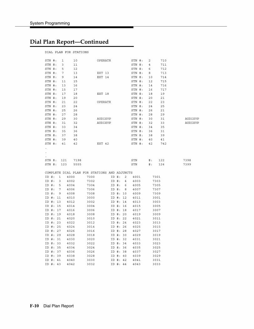
System Programming
F-10 Dial Plan Report
����������������������� 4
DIAL PLAN FOR STATIONS
STN #: 1 10 OPERATR STN #: 2 710STN #: 3 11 STN #: 4 711STN #: 5 12 STN #: 6 712STN #: 7 13 EXT 13 STN #: 8 713STN #: 9 14 EXT 14 STN #: 10 714STN #: 11 15 STN #: 12 715STN #: 13 16 STN #: 14 716STN #: 15 17 STN #: 16 717STN #: 17 18 EXT 18 STN #: 18 19STN #: 19 20 STN #: 20 21STN #: 21 22 OPERATR STN #: 22 23STN #: 23 24 STN #: 24 25STN #: 25 26 STN #: 26 21STN #: 27 28 STN #: 28 29STN #: 29 30 AUDIXVP STN #: 30 31 AUDIXVPSTN #: 31 32 AUDIXVP STN #: 32 33 AUDIXVPSTN #: 33 34 STN #: 34 35STN #: 35 36 STN #: 36 31STN #: 37 38 STN #: 38 39STN #: 39 40 STN #: 40 41STN #: 41 42 EXT 42 STN #: 42 742...STN #: 121 7198 STN #: 122 7398STN #: 123 5555 STN #: 124 7399
COMPLETE DIAL PLAN FOR STATIONS AND ADJUNCTSID #: 1 4000 7300 ID #: 2 4001 7301ID #: 3 4002 7302 ID #: 4 4003 7303ID #: 5 4004 7304 ID #: 6 4005 7305ID #: 7 4006 7306 ID #: 8 4007 7307ID #: 9 4008 7308 ID #: 10 4009 7309ID #: 11 4010 3000 ID #: 12 4011 3001ID #: 13 4012 3002 ID #: 14 4013 3003ID #: 15 4014 3004 ID #: 16 4015 3005ID #: 17 4016 3006 ID #: 18 4017 3007ID #: 19 4018 3008 ID #: 20 4019 3009ID #: 21 4020 3010 ID #: 22 4021 3011ID #: 23 4022 3012 ID #: 24 4023 3013ID #: 25 4024 3014 ID #: 26 4025 3015ID #: 27 4026 3016 ID #: 28 4027 3017ID #: 29 4028 3018 ID #: 30 4029 3019ID #: 31 4030 3020 ID #: 32 4031 3021ID #: 33 4032 3022 ID #: 34 4033 3023ID #: 35 4034 3024 ID #: 36 4035 3025ID #: 37 4036 3026 ID #: 38 4037 3027ID #: 39 4038 3028 ID #: 40 4039 3029ID #: 41 4040 3030 ID #: 42 4041 3031ID #: 43 4042 3032 ID #: 44 4043 3033
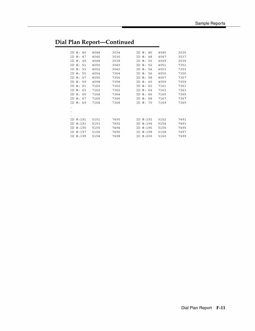
Sample Reports
Dial Plan Report F-11
����������������������� 4
ID #: 45 4044 3034 ID #: 46 4045 3035ID #: 47 4046 3036 ID #: 48 4047 3037ID #: 49 4048 3038 ID #: 50 4049 3039ID #: 51 4050 3040 ID #: 52 4051 7351ID #: 53 4052 3042 ID #: 54 4053 7353ID #: 55 4054 7354 ID #: 56 4055 7355ID #: 57 4056 7356 ID #: 58 4057 7357ID #: 59 4058 7358 ID #: 60 4059 7359ID #: 61 7160 7360 ID #: 62 7161 7361ID #: 63 7162 7362 ID #: 64 7163 7363ID #: 65 7164 7364 ID #: 66 7165 7365ID #: 67 7166 7366 ID #: 68 7167 7367ID #: 69 7168 7368 ID #: 70 7169 7369. . . ID #:191 5151 7490 ID #:192 5152 7491ID #:193 5153 7492 ID #:194 5154 7493ID #:195 5155 7494 ID #:196 5156 7495ID #:197 5156 7496 ID #:198 5158 7497ID #:199 5158 7498 ID #:200 5160 7499

System Programming
F-12 Label Information Report
������������������� 4
Print Menu Option: LabelsSections: Telephone Personal Directory; Posted Messages and Numbers
LABEL INFORMATION
Executive Telephone # 10: Personal Directory
Name Number Display
Executive Telephone # 14: Personal Directory
Name Number Display
Executive Telephone # 15: Personal Directory
Name Number DisplayMSG # POSTED MESSAGE
1 DO NOT DISTURB 2 OUT TO LUNCH 3 AT HOME 4 OUT SICK 5 IN A MEETING 6 IN CONFERENCE 7 WITH A CLIENT 8 WITH A CUSTOMER 9 AWAY FROM DESK 10 OUT ALL DAY 11 CUSTM MSG11 12 CUSTM MSG12 13 CUSTM MSG13 14 CUSTM MSG14 15 CUSTM MSG15 16 CUSTM MSG16 17 CUSTM MSG17 18 CUSTM MSG18 19 CUSTM MSG19 20 CUSTM MSG20

Sample Reports
Tie Trunk Information Report F-13
���������������������� 4
Print Menu Option: Trunk Info and TIE
TIE TRUNK INFORMATION
TRUNK XXX Slot/Port : ss/pp TIE-PBX or TollDirection : 2 Way E&M Signal: Type1S Dialtone : Local
: Outgoing : Type1C : Remote: InComing : Type5
InType : Immed InMode : Rotary AnsSupvr : XXX ms: Wink : Touchtone: Delay: Auto
OutType : Immed Outmode : Rotary Disconnect : XXX ms: Wink : Touchtone: Delay: Delay: Auto

System Programming
F-14 DID Trunk Information Report
���������������������� 4
Print Menu Option: Trunk Info and DID
DID TRUNK INFORMATION
Trk SS/PP Blk DiscTime Type ExpDig DelDig AddDig Signal InvDest841 13/ 1 1 500ms Wink 4 3 1 TouchTone BkupExt842 13/ 2 1 500ms Wink 4 3 1 TouchTone BkupExt843 13/ 3 2 500ms Wink 3 0 Rotary BkupExt844 13/ 4 2 500ms Wink 3 0 Rotary BkupExt845 13/ 5 1 500ms Wink 4 3 1 TouchTone BkupExt846 13/ 6 1 500ms Wink 4 3 1 TouchTone BkupExt847 13/ 7 2 500ms Wink 3 0 Rotary BkupExt848 13/ 8 1 500ms Wink 4 3 1 TouchTone BkupExt

Sample Reports
GS/LS Trunk Information Report F-15
�� ��������������������� 4
Print Menu Option: Trunk Info and Loop/Ground
GS/LS TRUNK INFORMATION
Trk SS/PP Type OutMode RelDisc ChannelUnit LS-ID Delay801 2/ 1 Loop TouchTone Yes N/A N/A802 2/ 2 Loop TouchTone Yes N/A N/A803 2/ 3 Loop TouchTone Yes N/A N/A804 2/ 4 Loop TouchTone Yes N/A N/A805 4/ 1 Loop Rotary Yes N/A N/A806 4/ 2 Loop Rotary Yes N/A N/A807 4/ 3 Loop Rotary Yes N/A N/A808 4/ 4 Loop Rotary Yes N/A N/A809 5/ 1 Ground TouchTone N/A N/A N/A810 5/ 2 Ground TouchTone N/A N/A N/A811 5/ 3 Loop Rotary Yes N/A N/A812 5/ 4 Loop Rotary Yes N/A N/A813 5/ 5 Loop Rotary Yes N/A N/A814 5/ 6 Loop Rotary Yes N/A N/A815 5/ 7 Loop TouchTone Yes N/A N/A816 5/ 8 Loop Rotary Yes N/A N/A817 6/ 1 Ground Rotary N/A N/A N/A..879 15/ 7 LS-ID Rotary Yes N/A Yes880 15/ 8 LS-ID Rotary Yes N/A No

System Programming
F-16 General Trunk Information Report
������������������������� 4
Print Menu Option: Trunk Info and General
805 4/ 1 No Remote Yes Long 4
GENERAL TRUNK INFORMATION
Trk SS/PP RemAccess Pool TlPrfx HldDisc Principal QCC QCC ExternPrty Oper Switch
801 2/ 1 No Remote 70 Yes Long 4802 2/ 2 No Remote 70 Yes Long 4803 2/ 3 No Remote 70 Yes Long 4804 2/ 4 No Remote Yes Long 4805 4/ 1 No Remote Yes Long 4806 4/ 2 No Remote Yes Long 4807 4/ 3 No Remote Yes Long 4808 4/ 4 No Remote Yes Long 4809 5/ 1 No Remote 890 Yes Long 4 10810 5/ 2 No Remote Yes Long 4811 5/ 3 No Remote Yes Long 4812 5/ 4 No Remote Yes Long 4813 5/ 5 No Remote Yes Long 4814 5/ 6 No Remote Yes Long 4815 5/ 7 No Remote Yes Long 4816 5/ 8 No Remote Yes Long 4817 6/ 1 Dedicated Yes Long 4..912 10/1 No Remote Yes Long 4913 10/2 No Remote Yes Long 4

Sample Reports
Switch 56 Data Information Report F-17
����!"�#$������������������� 4
Print Menu Option: Trunk Info and S56 Data
Dial Plan Routing for Network Service
Expected Digits: 3 Digits to Delete: 0 Digits to Add: 0
Trk ss/pp
Dirction InType OutType AnsSup Discnt
Inmode Outmode Service
Trk 02/01
2 Way Wink Wink 120 180 T-Tone T-Tone TIE
Trk 02/02
Outgoing Delay Delay 160 180 Rotary T-Tone S56
Trk 02/03
Incoming Auto Auto 100 140 Rotary Rotary S56
.
.
.808 02/
082 Way Wink Wink 120 180 Rotary Rotary TIE

System Programming
F-18 DS1 Information Report
��%�������������� 4
Print Menu Option: T1 Info
DS1 SLOT ATTRIBUTES
Slot Type Format Supp Signal LineComp ClkSync Src Active 3 T1 D4 ZCS Rob Bit 1 Prim Loop Yes 3 T1 D4 ZCS Rob Bit 1 None Local Yes

Sample Reports
PRI Information Report F-19
����������������� 4
Print Menu Option: PRI InfoSections: Network Selection, Special Service, Call-by-Call and Dial Plan
Routing Tables; PRI Information
NOTE:The B-Channels are printed in the order in which they are searched.
PRI INFORMATION
Slot 5 Switch: DMS-100
Slot 11 Switch: Legend-PBX
Slot 12 Switch: Legend-PBX
System: By line
BchnlGrp #: Slot: TestTelNum: NtwkServ: Incoming Routing:5 5 CallbyCall By Dial PlanChannel ID: 23 22 21 20 19 18 17 16 15 14
13 12 11 10 9 8 7 6 5 43 2 1
Line PhoneNumber NumberToSend801802803...821822823
BchnlGrp #: Slot: TestTelNum: NtwkServ: Incoming Routing:79 12 ElecTandNtwk Route Directly to UDPChannel ID: 1 2 3 4 5 6 7 8 9 10
11 12 13 14 15 16 17 18 19 2021 22 23
Line PhoneNumber NumberToSend849850851...869870871

System Programming
F-20 PRI Information Report
�������������������������� 4
BchnlGrp #: Slot: TestTelNum: NtwkServ: Incoming Routing:80 11 ElecTandNtwk Route Directly to UDPChannel ID: 1 2 3 4 5 6 7 8 9 10
11 12 13 14 15 16 17 18 19 2021 22 23
Line PhoneNumber NumberToSend825826827...845846847
Network Selection TableEntry Number: 0 1 3Pattern to Match: 101**** 10***Special Service TableEntry Number: 0 1 2 3 4 5 6 7Pattern to Match: 011 010 01 00 0 1Operator: none OP OP OP/P none none none noneType of Number: I I I N N N N NDigits to Delete: 3 3 2 2 1 0 0 0
Call-By-Call Service Table 2 3 4Entry Number: 0 1Pattern 0: 957 7Pattern 1: 1Pattern 2: 2Pattern 3: 3Pattern 4: 4Pattern 5: 5Pattern 6: 6Pattern 7: 7Pattern 8: 8Pattern 9: 9Call Type: BOTH BOTH BOTH BOTH BOTHNtwkServ: DMS-Private DMS-PrivateDeleteDigits: 0 0 0 0 0Entry Number: 5 6 7 8 9Call Type: BOTH BOTH BOTH BOTH BOTHNtwkServ:DeleteDigits: 0 0 0 0 0

Sample Reports
PRI Information Report F-21
�������������������������� 4
Dial Plan Routing Table
Entry Number: 0 1 2 3NtwkServ: Any service Any service Any serviceExpected Digits: 4 7 10 0Digits to Delete: 0 7 10 0Digits to Add: 13 13
Entry Number: 4 5 6 7NtwkServ:Expected Digits: 0 0 0 0Pattern to Match:Digits to Delete 0 0 0 0Digits to Add:
Entry Number: 8 9 10 11NtwkServ:Expected Digits: 0 0 0 0Pattern to Match:Digits to Delete: 0 0 0 0Digits to Add:
Entry Number: 12 13 14 15NtwkServ:Expected Digits: 0 0 0 0Pattern to Match:Digits to Delete: 0 0 0 0Digits to Add:

System Programming
F-22 Remote Access (DISA) Information Report
������&!!����'���&(��������� ���� 4
Print Menu Option: RmoteAccessSections: General Options; System Default Class of Restrictions (Non-
TIE); System Default Class of Restrictions (TIE); Barrier Code Administration
GENERAL OPTIONS (ACCESS CODE 889)
Barrier Code required for Non-TIE DISA lines : YesBarrier Code required for TIE DISA lines :NoAutomatic Queuing enabled for DISA lines :YesSystem Wide Barrier Code Length: 07Date And Time of Last Barrier Code Length Change: 09:23:94, 09:45 PM
SYSTEM DEFAULT CLASS OF RESTRICTIONS (NON-TIE)
Restriction : UNRESTRICTEDARS Restriction Level: 3Allowed Lists :Disallowed Lists :
SYSTEM DEFAULT CLASS OF RESTRICTIONS (TIE)
Restriction : UNRESTRICTEDARS Restriction Level: 3Allowed Lists :Disallowed Lists :
BARRIER CODE ADMINISTRATION
Barrier Code number : 1Barrier Digits : 2468345Restriction : OUTWARD RESTRICTEDARS Restriction Level: 3Allowed Lists :Disallowed Lists :
Barrier Code number : 2Barrier Digits : 1234693Restriction : UNRESTRICTEDARS Restriction Level: 3Allowed Lists :Disallowed Lists :..Barrier Code number : 16Barrier Digits : 9876115Restriction : OUTWARD RESTRICTEDARS Restriction Level: 0Allowed Lists :Disallowed Lists :

Sample Reports
Operator Information Report F-23
������������������ 4
Print Menu Option: Oper InfoSections: Operator Positions; General Options; DSS Options; QCC
Operator Options: QCC Call Types
OPERATOR POSITIONS
PORT CALL ALERTADDR. EXT # LABEL TYPE (QCC ONLY)==== ===== ======= ==== ==========1/ 1 10 OPERATR QCC No1/ 5 14 EXT 14 DLC N/A2/ 1 18 EXT 18 DLC N/A2/ 5 22 OPERATR DLC N/A6/ 1 42 EXT 42 DLC N/A
GENERAL OPTIONS
Length of hold reminder timer: 60 secDLC Automatic hold enabled : No
DIRECT STATION SELECTOR (DSS) OPTIONS
BUTTON FIRSTNUMBER DIAL CODE====== =========1 02 503 100
Operator Call Park codes: 881 882 883 884 885 886 884 888
QCC OPERATOR OPTIONS
Listed Directory Number for queue : 800Held calls return to queue : NoAutomatic hold enabled : NoCalls-in-queue alarm threshold : 0Time until priorities are elevated: 0 secMessage Center Operators :One Touch Extend : AUTOMATICRings before extended calls return: 4Backup operator station :Voice Announce on Call 5 button : Disable

System Programming
F-24 Operator Information Report
��������������������������� 4
QCC CALL TYPES: CALL TYPE PRIORITY OPERATORS======================= ======== ===================Dial 0 Operator 4 10Follow Forward 4 N/AUnassigned DID 4 10Listed Directory Number 4 10Operator’s Extension 4 N/AReturning 4 0Group Coverage Group # 1 4
Group # 2 4 Group # 3 4 Group # 4 4 Group # 5 4 Group # 6 4 Group # 7 4 Group # 8 4 Group # 9 4 Group # 10 4 Group # 11 4 Group # 12 4 Group # 13 4 Group # 14 4 Group # 15 4 Group # 16 4 Group # 17 4 Group # 18 4 Group # 19 4 Group # 20 4 Group # 21 4 Group # 22 4 Group # 23 4 Group # 24 4 Group # 25 4 Group # 26 4 Group # 27 4 Group # 28 4 Group # 29 4 Group # 30 4

Sample Reports
Allowed Lists Report F-25
&���������������� 4
Print Menu Option: AllowListSections: Lists 1 through 7
ALLOWED LISTS
List : 0
Entry 0: ------Entry 1: ------Entry 2: ------Entry 3: ------Entry 4: ------Entry 5: ------Entry 6: ------Entry 7: ------Entry 8: ------Entry 9: ------...List : 7
Entry 0: ------Entry 1: ------Entry 2: ------Entry 3: ------Entry 4: ------Entry 5: ------Entry 6: ------Entry 7: ------Entry 8: ------Entry 9: ------

System Programming
F-26 Access to Allowed Lists Report
&!!������&���������������� 4
Print Menu Option: AllowListTo
ACCESS TO ALLOWED LISTS
FOR REMOTE ACCESS 17 & 18 MEAN TIE & NON-TIE RESTRICTIONS
List 1 STNS 10
RACC 1 17 18
List 3 STNS 33
RACC
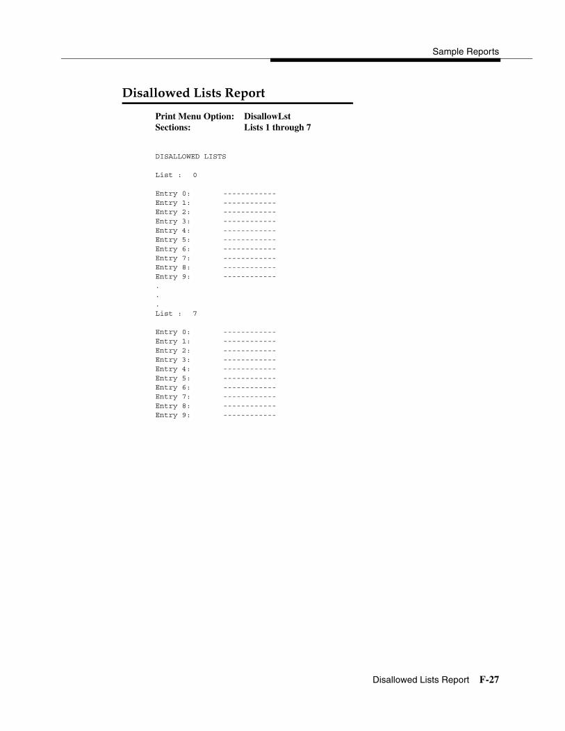
Sample Reports
Disallowed Lists Report F-27
�������������������� 4
Print Menu Option: DisallowLstSections: Lists 1 through 7
DISALLOWED LISTS
List : 0
Entry 0: ------------Entry 1: ------------Entry 2: ------------Entry 3: ------------Entry 4: ------------Entry 5: ------------Entry 6: ------------Entry 7: ------------Entry 8: ------------Entry 9: ------------...List : 7
Entry 0: ------------Entry 1: ------------Entry 2: ------------Entry 3: ------------Entry 4: ------------Entry 5: ------------Entry 6: ------------Entry 7: ------------Entry 8: ------------Entry 9: ------------

System Programming
F-28 Access to Disallowed Lists Report
&!!�������������������������� 4
Print Menu Option: DisallowTo
ACCESS TO DISALLOWED LISTS
FOR REMOTE ACCESS 17 & 18 MEAN TIE & NON-TIE RESTRICTIONS
List 1 STNS 33
RACC 9
List 3 STNS 33
RACC

Sample Reports
Automatic Route Selection Report F-29
&������!����������!�������� 4
Print Menu Option: ARSSections: Tables
AUTOMATIC ROUTE SELECTION
ARS IS: ACTIVE ACCESS CODE: 9
TABLE 17: Default Toll Output Table
Pool Absorb Other Digits FRL Call type Start Pattern1)70-- 00 ------------------- 3 BOTH --:-- A2)---- -- -------------------- ----- --:-- A 3)---- -- -------------------- ----- --:-- A4)---- -- -------------------- ----- --:-- A5)---- -- -------------------- ----- --:-- B6)---- -- -------------------- ----- --:-- B
Pool Absorb Other Digits FRL Call type Start Pattern1)70-- 00 ------------------- 3 BOTH --:-- B2)---- -- -------------------- ----- --:-- B3)---- -- -------------------- ----- --:-- B4)---- -- -------------------- ----- --:-- B5)---- -- -------------------- ----- --:-- B6)---- -- -------------------- ----- --:-- B
TABLE 18: Default Local Output Table
Pool Absorb Other Digits FRL Call type Start Pattern1)70-- 00 ------------------- 3 BOTH --:-- A2)---- -- -------------------- ----- --:-- A 3)---- -- -------------------- ----- --:-- A4)---- -- -------------------- ----- --:-- A5)---- -- -------------------- ----- --:-- B6)---- -- -------------------- ----- --:-- B
Pool Absorb Other Digits FRL Call type Start Pattern1)70-- 00 ------------------- 3 BOTH --:-- B2)---- -- -------------------- ----- --:-- B3)---- -- -------------------- ----- --:-- B4)---- -- -------------------- ----- --:-- B5)---- -- -------------------- ----- --:-- B
TABLE 19: Dial 0 Output Table
Pool Absorb Other Digits FRL Call type Start Pattern1)70-- 00 ------------------- 3 BOTH --:-- A
TABLE 20: N11 Output Table01)411 02)611 03)811 04)911
Pool Absorb Other Digits FRL Call type Start Pattern1)70-- 00 ------------------- 3 BOTH --:-- A1)70-- 00 ------------------- 3 BOTH --:-- A
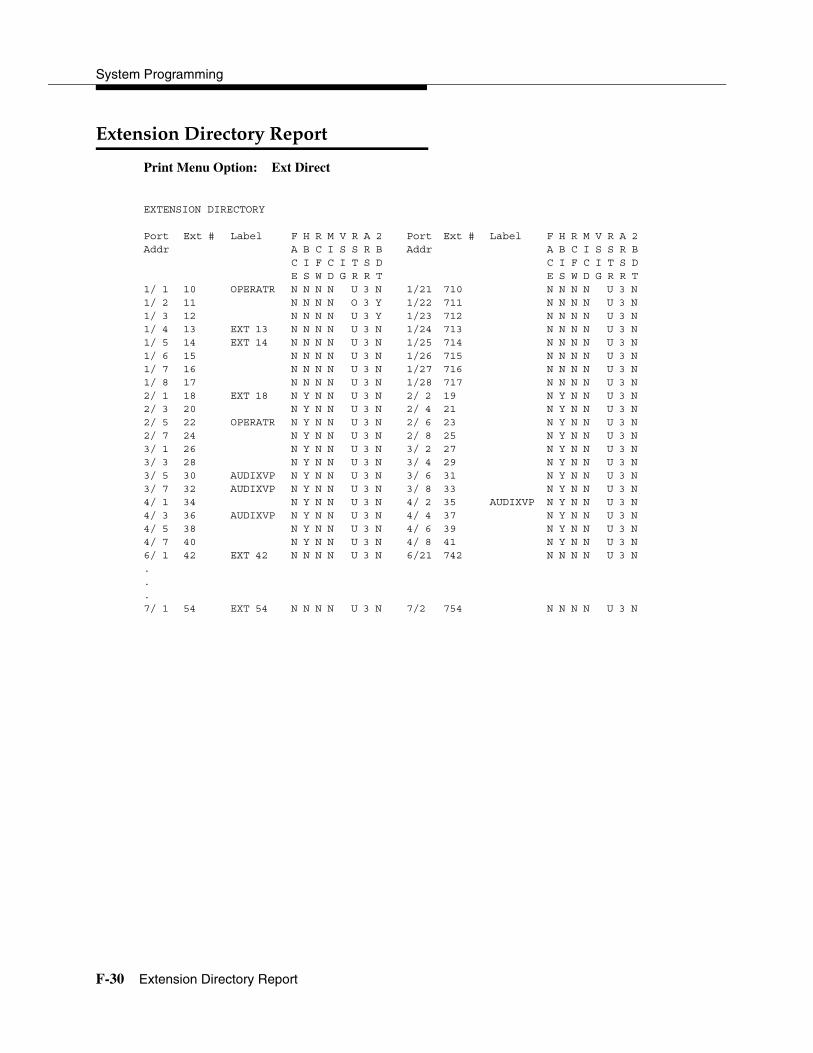
System Programming
F-30 Extension Directory Report
)*����������!������� 4
Print Menu Option: Ext Direct
EXTENSION DIRECTORY
Port Ext # Label F H R M V R A 2 Port Ext # Label F H R M V R A 2Addr A B C I S S R B Addr A B C I S S R B
C I F C I T S D C I F C I T S DE S W D G R R T E S W D G R R T
1/ 1 10 OPERATR N N N N U 3 N 1/21 710 N N N N U 3 N1/ 2 11 N N N N O 3 Y 1/22 711 N N N N U 3 N1/ 3 12 N N N N U 3 Y 1/23 712 N N N N U 3 N1/ 4 13 EXT 13 N N N N U 3 N 1/24 713 N N N N U 3 N1/ 5 14 EXT 14 N N N N U 3 N 1/25 714 N N N N U 3 N1/ 6 15 N N N N U 3 N 1/26 715 N N N N U 3 N1/ 7 16 N N N N U 3 N 1/27 716 N N N N U 3 N1/ 8 17 N N N N U 3 N 1/28 717 N N N N U 3 N2/ 1 18 EXT 18 N Y N N U 3 N 2/ 2 19 N Y N N U 3 N2/ 3 20 N Y N N U 3 N 2/ 4 21 N Y N N U 3 N2/ 5 22 OPERATR N Y N N U 3 N 2/ 6 23 N Y N N U 3 N2/ 7 24 N Y N N U 3 N 2/ 8 25 N Y N N U 3 N3/ 1 26 N Y N N U 3 N 3/ 2 27 N Y N N U 3 N3/ 3 28 N Y N N U 3 N 3/ 4 29 N Y N N U 3 N3/ 5 30 AUDIXVP N Y N N U 3 N 3/ 6 31 N Y N N U 3 N3/ 7 32 AUDIXVP N Y N N U 3 N 3/ 8 33 N Y N N U 3 N4/ 1 34 N Y N N U 3 N 4/ 2 35 AUDIXVP N Y N N U 3 N4/ 3 36 AUDIXVP N Y N N U 3 N 4/ 4 37 N Y N N U 3 N4/ 5 38 N Y N N U 3 N 4/ 6 39 N Y N N U 3 N4/ 7 40 N Y N N U 3 N 4/ 8 41 N Y N N U 3 N6/ 1 42 EXT 42 N N N N U 3 N 6/21 742 N N N N U 3 N. . . 7/ 1 54 EXT 54 N N N N U 3 N 7/2 754 N N N N U 3 N
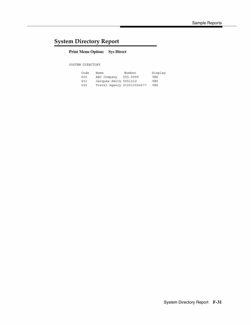
Sample Reports
System Directory Report F-31
����������!������� 4
Print Menu Option: Sys Direct
SYSTEM DIRECTORY
Code Name Number Display600 ABC Company 555-9999 YES601 Jacques Smith 5551212 YES605 Travel Agency 912015556677 YES
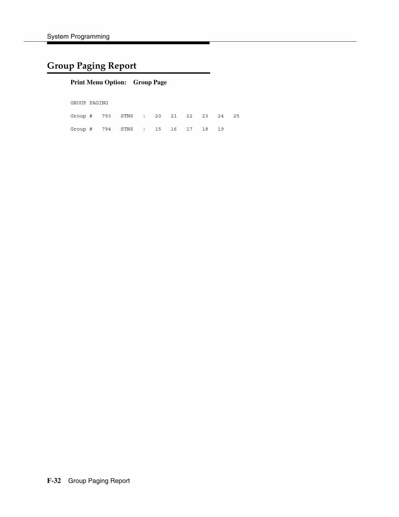
System Programming
F-32 Group Paging Report
������+��+����� 4
Print Menu Option: Group Page
GROUP PAGING
Group # 793 STNS : 20 21 22 23 24 25
Group # 794 STNS : 15 16 17 18 19

Sample Reports
Extension Information Report F-33
)*�������������������� 4
Print Menu Option: Ext Info plus extension number
EXTENSION INFORMATION
Extn SS/PP Type 10 1/ 1 MLX-20L + 1 DSS
CTI Link : NO Alarms: ACTIVE (SUSPENDED)Pool Access : 70 890 891 892 893 894 895 896 897 898 Page Group :Primary Coverage :Secondary Coverage :Coverage Group : 5Group Coverers : 773NS Groups : 10Group Calling Member :Pickup Groups : Allowed Lists : Disallowed Lists : Restrictions : UNRESTRICTEDESS Sup. Status : ACTIVEESS Restrictions : ESS-0 -NO RESTRICTIONAuto Callback : OFFCall Waiting : ONAbbreviated Ring : ONLine Preference : ONShared SA Ring : ONReceive Voice Calls : ONCoverage Inside : OFFForwarding to : Delay Forwarding : 0ARS Restriction : 3Forced Account Code : NoMicrophone Disable : NoRotary Enable : NoRemote Forward Allow : NoTrunk Transfer Allow : NoNS Exclusion : NoVoice Announce Pair : NoVoice/Data Pair : NoBIS/HFAI : NoLanguage : EnglishAuthorization Code : 31342B Data Port : NoPrimary Ring Delay : 2Secondary Ring Delay : 2Group Cover Delay : 3HotLine Extension : NoDisplay Preference : NAME Service Observer : 10Service Observing Group : 6802 6804

System Programming
F-34 Extension Information Report
)*����������������������������� 4
EXTENSION INFORMATION
Extn SS/PP Type 10 1/ 1 MLX-20L + 1 DSS
Button 34 Blank Status NoneButton 33 Blank Status NoneButton 32 Blank Status NoneButton 31 Blank Status NoneButton 30 Blank Status NoneButton 29 Blank Status NoneButton 28 Blank Status NoneButton 27 Blank Status NoneButton 26 Blank Status NoneButton 25 Blank Status NoneButton 24 Blank Status NoneButton 23 Blank Status NoneButton 22 Blank Status NoneButton 21 Blank Status NoneButton 20 Forced Release Status NoneButton 19 Pool Inspect Status NoneButton 18 Headset Auto Answer Status OffButton 17 Join Status NoneButton 16 Cancel Status NoneButton 15 Alarm Status Status OffButton 14 Night Service Status OffButton 13 Headset Status Status OffButton 12 Destination Status NoneButton 11 Release Status NoneButton 10 Position Busy Status OffButton 9 Send/Remove Message Status NoneButton 8 Handset/Headset Mute Status OffButton 7 Source Status NoneButton 6 Start Status NoneButton 5 Call 5 Status NoneButton 4 Call 4 Status NoneButton 3 Call 3 Status NoneButton 2 Call 2 Status NoneButton 1 Call 1 Status None
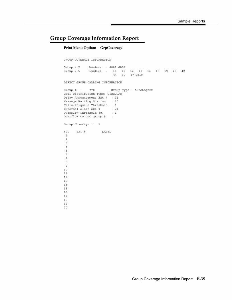
Sample Reports
Group Coverage Information Report F-35
��������+��������������� 4
Print Menu Option: GrpCoverage
GROUP COVERAGE INFORMATION
Group # 2 Senders : 6802 6804Group # 5 Senders : 10 11 12 13 14 18 19 20 42
44 45 47 6810
DIRECT GROUP CALLING INFORMATION
Group # : 770 Group Type : AutoLogoutCall Distribution Type: CIRCULARDelay Announcement Ext # : 11Message Waiting Station : 20Calls-in-queue Threshold : 1External Alert ext # : 21Overflow Threshold (#) : 1Overflow to DGC group # :
Group Coverage : 1
No. EXT # LABEL 1 2 3 4 5 6 7 8 91011121314151617181920

System Programming
F-36 Direct Group Calling Information Report
���!������������+��������� ���� 4
Print Menu Option: Grp CallingSections: Each programmed group
DIRECT GROUP CALLING INFORMATIONGroup # : 782 Group Type : AutoLogoutCall Distribution Type : CIRCULAR
PryAnn No. Ext # LABEL 1 27 ANN1 2 28 ANN2
Secondary Announcement Ext # : 29Time Between Delay Announcements : 0Repeat Secondary Announcement: NO
Message Waiting Station : NONEQueue Control Limit: Calls-in-queue Threshold 1: 1Calls-in-queue Threshold 2: 1Calls-in-queue Threshold 3: 1External Alert ext # : NONEOverflow Threshold (#) : 1Overflow Threshold (Time): 0Prompt Based Overflow Option: NOOverflow to DGC group # : NONE
Group Coverage : 1Member No. EXT # LABEL 1 12 2 13 3 4 5 6 7 8 9 10 11 12 13 14 15 16 17 18 19 20LINES:Group Priority:16Support Group:Home Group(s)/Priority:

Sample Reports
Night Service Information Report F-37
,�+"������!��������������� 4
Print Menu Option: Night Servce
NIGHT SERVICE INFORMATION
OPERATOR 10 DGCG #:STNS : 10LINES : 801
OPERATOR 14 DGCG #:STNS : 14LINES : 804
OPERATOR 18 DGCG #:STNS : 18LINES : 808
OPERATOR 22 DGCG #:STNS : 22LINES : 822
OPERATOR 42 DGCG #:STNS : 42LINES : 842
Password :Current Day : OFF
Turn off at: Turn on at: Sunday : : Monday : : Tuesday : : Wednesday : : Thursday : : Friday : : Saturday : :Emergency Allowed List: 0) 1) 2) 3) 4) 5) 6) 7) 8) 9)NS Excluded STNS: 61 62 63 64 65Coverage Control Enabled: YES

System Programming
F-38 Group Call Pickup Report
�����������!�������� 4
Print Menu Option: Call Pickup
GROUP CALL PICKUP
Group # 1 STNS : 10 11 12 13 I4 15 16Group # 2 STNS : 17 18 19 20Group # 3 STNS : 21 22 23 24 25 26 27 28 29 30Group # 4 STNS : 31Group # 5 STNS : 32Group # 6 STNS : 33Group # 7 STNS : 34Group # 8 STNS : 35Group # 9 STNS : 36Group # 10 STNS : 37

Sample Reports
Error Log Report F-39
)��+����� 4
Print Menu Option: Error Log
ERROR LOG
Last 30 System Errors:
Message ss/pp Cnt First Last CodePRI SVC AUDIT TIMEOUT 00/00 - - 01/08 00:00:53 7001TIMEOUT COLD START 00/00 - - 01/11 00:04:08 0001PRI SVC AUDIT TIMEOUT 00/00 - - 01/11 00:04:14 7001TIMEOUT COLD START 00/00 - - 01/21 00:22:14 0001PRI SVC AUDIT TIMEOUT 00/00 - - 01/03 00:22:14 7001PRI SVC AUDIT TIMEOUT 00/00 - - 01/04 00:22:14 7001SOFTWARE COLD START 00/00 - - 01/04 00:21:14 0003SOFTWARE COLD START 00/00 - - 01/04 00:21:14 0003PRI SVC AUDIT TIMEOUT 00/00 - - 01/04 00:21:14 7001SOFTWARE COLD START 00/00 - - 01/04 00:22:11 0003PRI SVC AUDIT TIMEOUT 00/00 - - 01/08 00:00:53 7001TIMEOUT COLD START 00/00 - - 02/11 00:04:08 0001PRI SVC AUDIT TIMEOUT 00/00 - - 02/11 00:04:14 7001TIMEOUT COLD START 00/00 - - 02/21 00:22:14 0001PRI SVC AUDIT TIMEOUT 00/00 - - 02/03 00:22:14 7001PRI SVC AUDIT TIMEOUT 00/00 - - 02/04 00:22:14 7001SOFTWARE COLD START 00/00 - - 02/04 00:21:14 0003SOFTWARE COLD START 00/00 - - 02/04 00:21:14 0003PRI SVC AUDIT TIMEOUT 00/00 - - 02/04 00:21:14 7001SOFTWARE COLD START 00/00 - - 02/04 00:22:11 0003PRI SVC AUDIT TIMEOUT 00/00 - - 02/08 00:00:53 7001TIMEOUT COLD START 00/00 - - 03/11 00:04:08 0001PRI SVC AUDIT TIMEOUT 00/00 - - 03/11 00:04:14 7001TIMEOUT COLD START 00/00 - - 03/21 00:22:14 0001PRI SVC AUDIT TIMEOUT 00/00 - - 03/03 00:22:14 7001PRI SVC AUDIT TIMEOUT 00/00 - - 03/04 00:22:14 7001SOFTWARE COLD START 00/00 - - 03/04 00:21:14 0003SOFTWARE COLD START 00/00 - - 03/04 00:21:14 0003PRI SVC AUDIT TIMEOUT 00/00 - - 03/04 00:21:14 7001SOFTWARE COLD START 00/00 - - 03/04 00:22:11 0003

System Programming
F-40 Authorization Code Information Report
&��"�-����������������� ���� 4
Print Menu Option: Auth Code
SMDR Option for the Account Code Field is Home Extension
Extension Authorization Code 10 3124 15 1357921 20 6578 23 443796

Sample Reports
BRI Information Report F-41
.���������������� 4
Print Menu Option: BRI Info
BRI INFORMATION
Flexible Timers:T200 = 1000 ms T203 = 33 sec T303 = 4 sec T305 = 30 sec T308 = 4 sec
Fixed Timers and Counters:T202 = 2 sec T309 = 90 sec T310 = 60 sec T313 = 4 secK Cntr = 1 N200 = 3 N201 = 260 N202 = 3
Line Service Profile ID Directory Number 801 908555100001 9085551000 802 908555100101 9085551001 803 908555100201 9085551002 804 908555100301 9085551003 805 908555100401 9085551004 806 908555100501 9085551005 807 908555100601 9085551006 808 908555100701 9085551007

System Programming
F-42 Non-Local Dial Plan Report
,�/�!����������������� 4
Print Menu Option: NonLcl UDP (Release 6.0 and later systems only)Sections: Ranges; Patterns
Range Ptn Dgt Range PtnDgt Range Ptn Dgt01) 2400-2449 01 04 18)5200-5200 11 04 35)7590-7609 07 0402) 2550-2559 02 04 19)5201-5202 12 04 36)7610-7709 08 0403) 2560-2569 03 04 20)5203-5204 13 04 37)7710-7809 09 0404) 2570-2589 04 04 21)5205-5206 14 04 38)7810-7899 10 0405) 2590-2609 04 04 22)5207-5209 15 04 39)8050-8059 15 0406) 2610-2649 05 04 23)5210-5230 03 04 40)8060-8069 03 0407) 2650-2679 06 04 24)5231-5250 17 04 41)8070-8099 04 0408) 3100-3109 07 04 25)5251-5270 18 04 42)8100-8199 05 0409) 3110-3129 07 04 26)6050-6079 14 04 43)8200-8229 06 0410) 3130-3159 02 04 27)7000-7049 12 04 44)8230-8259 16 0411) 3160-3179 06 04 28)7050-7050 20 04 45)8260-8289 17 0412) 3180-3199 08 04 29)7051-7059 01 04 46)8290-8389 18 0413) 4000-4025 08 05 30)7060-7099 02 04 47)8390-8429 19 0414) 5000-5049 09 05 31)7100-7119 03 04 48)8430-8459 20 0415) 5050-5079 10 05 32)7220-7449 04 04 49)8460-8489 03 0416) 5080-5099 01 05 33)7450-7549 05 04 50)8490-8499 02 0417) 5100-5199 02 05 34)7550-7589 06 04 Pattern 01:Pool AbsorbOther DigitsFRLCall type1)387000 0 BOTH2)389200 0 BOTH3)389300 0 BOTH 4)3894 00 0 BOTH
Pattern 02:Pool AbsorbOther DigitsFRLCall type1)459000 2 BOTH2)459200 2 VOICE3)389300 0 BOTH 4)3894 00 0 BOTH. . . .. . . .
Pattern 20:Pool AbsorbOther DigitsFRLCall type1)459100 3 DATA 2)4592 00 3 DATA3)389400 3 BOTH 4)3870 00 4 BOTH
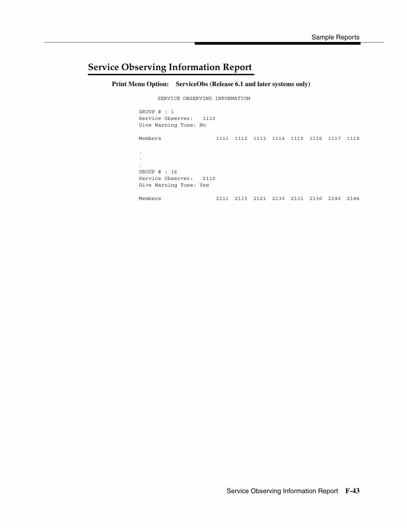
Sample Reports
Service Observing Information Report F-43
����!�� ������+�������������� 4
Print Menu Option: ServiceObs (Release 6.1 and later systems only)
SERVICE OBSERVING INFORMATION
GROUP # : 1 Service Observer: 1110
Give Warning Tone: No
Members 1111 1112 1113 1114 1115 1116 1117 1118
.
.
.GROUP # : 16
Service Observer: 2110Give Warning Tone: Yes
Members 2111 2115 2121 2130 2131 2136 2140 2144

System Programming
F-44 Service Observing Information Report

Basic System Operating Conditions G-1
G)� ����$���� �������� ��2�� �� G
This appendix lists the basic procedures, in the order in which they must be performed, to program a new system. In some instances, you may need to rearrange the system planning forms to match this order.
NOTE:If your MERLIN LEGEND System is part of a private network, contact the Network Engineering Group for assistance. Refer to the Network Reference for additional programming that is required.
3����$����������� ��� ����� � 4
� Select the system programming position:
System→SProg Port
� Select the system language:
More→Language→SystemLang
� Select the system mode:
System→Mode
� Enable Automatic Maintenance Busy:
System→MaintenBusy
� Set the system time:
System→Time

System Programming
G-2 System Renumbering
� Set the system date:
System→Date
� Schedule automatic backups:
System→Backup/Restore→Auto Backup
$������ ������ � 4
� Select the system numbering plan:
SysRenumber→Default Numbering
� Single renumbering:
SysRenumber→Single
� Block renumbering:
SysRenumber→Block
� DSS console page buttons:
SysRenumber→Single→More→DSS buttons
��� ���$$������������ ������ � 4
� Identify QCC system operator positions:
Operator→Positions→Queued Call
� Identify DLC system operator positions:
Operator→Positions→Direct Line
0� ��� ���� *� 4
� Specify type of trunk on 400 or 800 GL/LS module:
LinesTrunks →LS/GS/DS1
� Identify dial signaling for loop-start/ground-start trunks:
LinesTrunks→TT/LS Disc→Outmode
� Classify disconnect signaling reliability for loop-start trunks:
LinesTrunks→TT/LS Disc→LS Disconnect
� Specify toll prefix requirements:
LinesTrunks→Toll Type
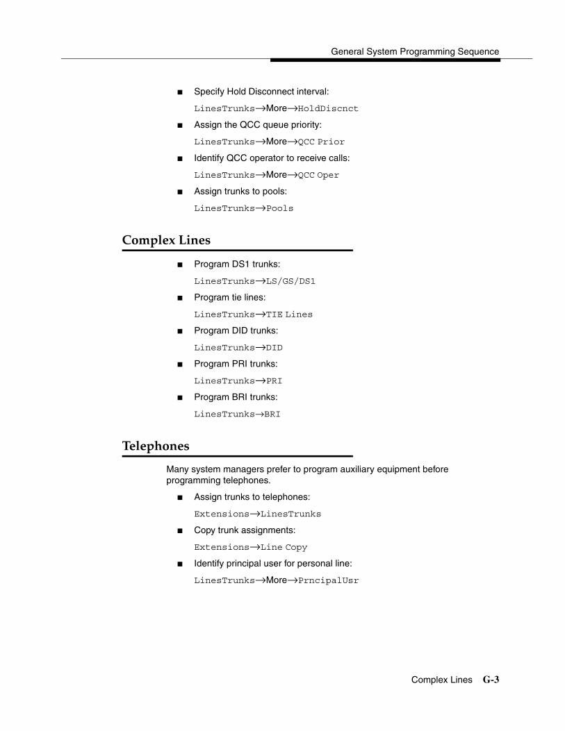
General System Programming Sequence
Complex Lines G-3
� Specify Hold Disconnect interval:
LinesTrunks→More→HoldDiscnct
� Assign the QCC queue priority:
LinesTrunks→More→QCC Prior
� Identify QCC operator to receive calls:
LinesTrunks→More→QCC Oper
� Assign trunks to pools:
LinesTrunks→Pools
������40� �� 4
� Program DS1 trunks:
LinesTrunks→LS/GS/DS1
� Program tie lines:
LinesTrunks→TIE Lines
� Program DID trunks:
LinesTrunks→DID
� Program PRI trunks:
LinesTrunks→PRI
� Program BRI trunks:
LinesTrunks→BRI
������� �� 4
Many system managers prefer to program auxiliary equipment before programming telephones.
� Assign trunks to telephones:
Extensions→LinesTrunks
� Copy trunk assignments:
Extensions→Line Copy
� Identify principal user for personal line:
LinesTrunks→More→PrncipalUsr
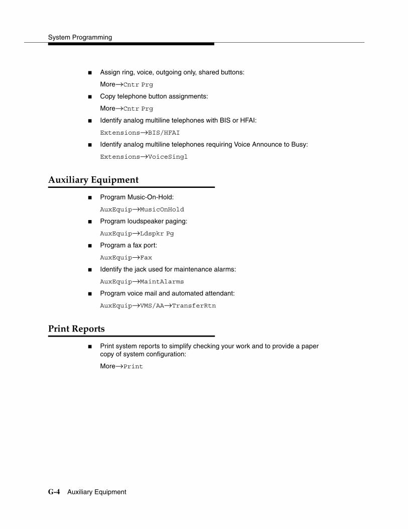
System Programming
G-4 Auxiliary Equipment
� Assign ring, voice, outgoing only, shared buttons:
More→Cntr Prg
� Copy telephone button assignments:
More→Cntr Prg
� Identify analog multiline telephones with BIS or HFAI:
Extensions→BIS/HFAI
� Identify analog multiline telephones requiring Voice Announce to Busy:
Extensions→VoiceSingl
+�4�����$�2����� � 4
� Program Music-On-Hold:
AuxEquip→MusicOnHold
� Program loudspeaker paging:
AuxEquip→Ldspkr Pg
� Program a fax port:
AuxEquip→Fax
� Identify the jack used for maintenance alarms:
AuxEquip→MaintAlarms
� Program voice mail and automated attendant:
AuxEquip→VMS/AA→TransferRtn
�� �������� 4
� Print system reports to simplify checking your work and to provide a paper copy of system configuration:
More→Print
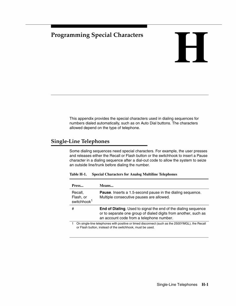
Single-Line Telephones H-1
H �������� ����������������� H
This appendix provides the special characters used in dialing sequences for numbers dialed automatically, such as on Auto Dial buttons. The characters allowed depend on the type of telephone.
� ���50� �������� �� 4
Some dialing sequences need special characters. For example, the user presses and releases either the Recall or Flash button or the switchhook to insert a Pause character in a dialing sequence after a dial-out code to allow the system to seize an outside line/trunk before dialing the number.
Table H-1. Special Characters for Analog Multiline Telephones
Press... Means...
Recall, Flash, or switchhook1
1 On single-line telephones with positive or timed disconnect (such as the 2500YMGL), the Recall or Flash button, instead of the switchhook, must be used.
Pause. Inserts a 1.5-second pause in the dialing sequence. Multiple consecutive pauses are allowed.
# End of Dialing. Used to signal the end of the dialing sequence or to separate one group of dialed digits from another, such as an account code from a telephone number.

System Programming
H-2 Analog Multiline Telephones
+ ����!������ �������� �� 4
Some dialing sequences need special characters. For example, the user presses Hold to insert a Pause character after the dial-out code in a dialing sequence to allow the system to seize an outside line before dialing the number. A Pause character can also be used to separate a telephone number from an extension number.
Table H-2. Special Characters for Analog Multiline Telephones
Press... See1...
1 Display telephones only.
Means...
Drop2 s Stop. Inserts a Stop within a sequence of automatically dialed numbers. For example, an outside Auto Dial button may be programmed with a password, then a Stop, then a telephone number. To use Auto Dial with a Stop in the sequence, the user presses the button to dial the password, listens for the dialing and connection, and presses the button again to dial the number.
Hold p Pause. Inserts a 1.5-second pause in the dialing sequence. Multiple consecutive pauses are allowed.
Conference2
2 Not available on MLC-5, MDC 9000, and MDW 9000 cordless and cordless/wireless telephones.
f Flash. Sends a switchhook flash. Must be the first entry in the dialing sequence.
## # End of Dialing for Auto Dial buttons. Used at the end of a dialing sequence to indicate that the user has finished dialing or to separate one group of dialed digits from another.
# # End of Dialing. Used at the end of a dialing sequence to indicate that the user has finished dialing or to separate one group of dialed digits from another.

Programming Special Characters
MLX-10 and MLX-5 Nondisplay Telephones H-3
!06578� �!0659�� ������$ ������� �� 4
Some dialing sequences need special characters. For example, the user presses Hold to insert a Pause character after the dial-out code in a dialing sequence to allow the system to seize an outside line before dialing the number. A Pause character can also be used to separate a telephone number from an extension number.
Table H-3. Special Characters for MLX-10 and MLX-5 Nondisplay Telephones
Press... Means...
Drop Stop. Halts the dialing sequence to allow for system response.
Hold Pause. Inserts a 1.5-second pause in the dialing sequence. Multiple consecutive pauses are allowed.
Conf Flash. Sends a switchhook flash. Must be the first entry in the dialing sequence.
# End of Dialing for extension programming only. Used at the end of a dialing sequence to indicate that the user has finished dialing or to separate one group of dialed digits from another.
## End of Dialing. Used to signal the end of the dialing sequence or to separate one group of dialed digits from another.
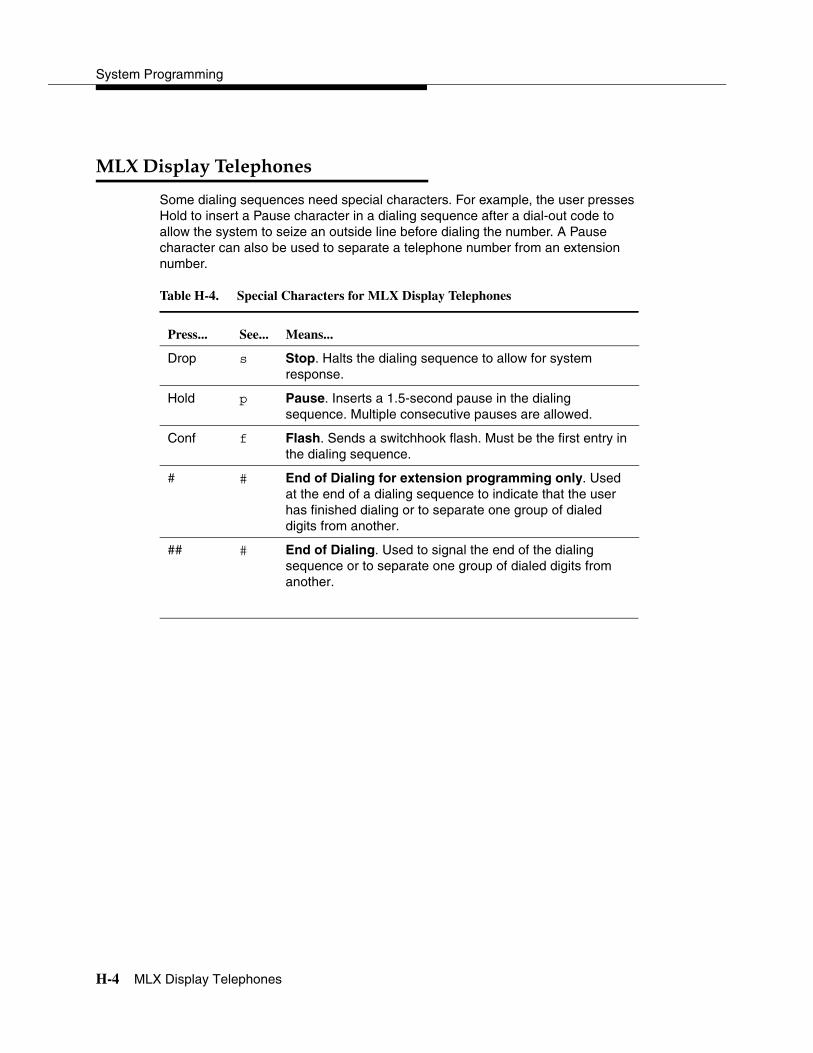
System Programming
H-4 MLX Display Telephones
!06������$������� �� 4
Some dialing sequences need special characters. For example, the user presses Hold to insert a Pause character in a dialing sequence after a dial-out code to allow the system to seize an outside line before dialing the number. A Pause character can also be used to separate a telephone number from an extension number.
Table H-4. Special Characters for MLX Display Telephones
Press... See... Means...
Drop s Stop. Halts the dialing sequence to allow for system response.
Hold p Pause. Inserts a 1.5-second pause in the dialing sequence. Multiple consecutive pauses are allowed.
Conf f Flash. Sends a switchhook flash. Must be the first entry in the dialing sequence.
# # End of Dialing for extension programming only. Used at the end of a dialing sequence to indicate that the user has finished dialing or to separate one group of dialed digits from another.
## # End of Dialing. Used to signal the end of the dialing sequence or to separate one group of dialed digits from another.

GL-1
)������$ GL
NOTE:The use of italics in this glossary denotes a cross-reference to other glossary entries or the expanded name for an acronym.
��������
+
2B Data Digital information carried by two B-channels for better performance and quality; the bit rate is twice that of one B-channel used alone.
7500B Data Module See ISDN 7500B Data Module.
Account Code Code used to associate incoming and outgoing calls with corresponding accounts, employees, projects, and clients.
ACCUNET AT&T’s switched digital service for 56-kbps, 64-kbps restricted, and 64-kbps clear circuit-switched data calls.
Address Coded representation of the destination of data or of the data’s originating terminal, such as the dialed extension number assigned to the data terminal. Multiple terminals on one communications line each must have a unique address.
ADDS Automated Document Delivery System. Computer-based application that stores documents in a database and automatically faxes them on request.
Adjunct Optional equipment used with the communications system, such as an alerting device or modem that connects to a multiline telephone or to an extension jack.
ALS Automatic Line Selection. Programmed order in which the system makes outside lines available to a user.
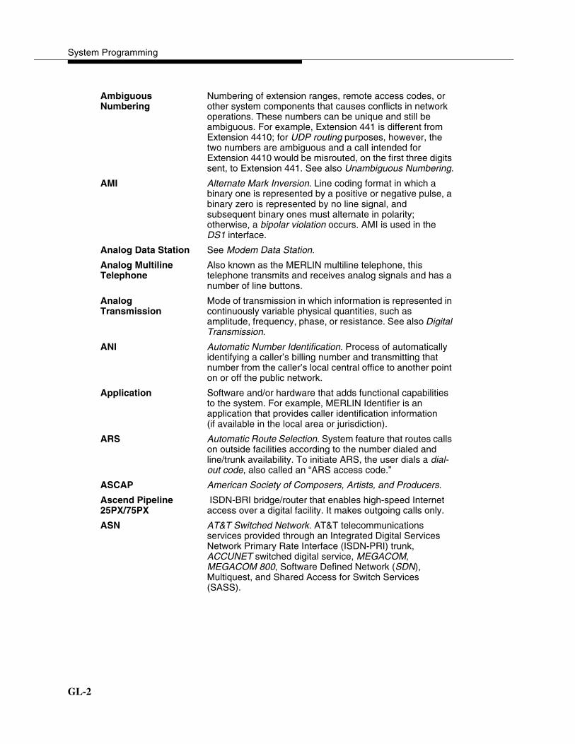
System Programming
GL-2
Ambiguous Numbering
Numbering of extension ranges, remote access codes, or other system components that causes conflicts in network operations. These numbers can be unique and still be ambiguous. For example, Extension 441 is different from Extension 4410; for UDP routing purposes, however, the two numbers are ambiguous and a call intended for Extension 4410 would be misrouted, on the first three digits sent, to Extension 441. See also Unambiguous Numbering.
AMI Alternate Mark Inversion. Line coding format in which a binary one is represented by a positive or negative pulse, a binary zero is represented by no line signal, and subsequent binary ones must alternate in polarity; otherwise, a bipolar violation occurs. AMI is used in the DS1 interface.
Analog Data Station See Modem Data Station.
Analog Multiline Telephone
Also known as the MERLIN multiline telephone, this telephone transmits and receives analog signals and has a number of line buttons.
Analog Transmission
Mode of transmission in which information is represented in continuously variable physical quantities, such as amplitude, frequency, phase, or resistance. See also Digital Transmission.
ANI Automatic Number Identification. Process of automatically identifying a caller’s billing number and transmitting that number from the caller’s local central office to another point on or off the public network.
Application Software and/or hardware that adds functional capabilities to the system. For example, MERLIN Identifier is an application that provides caller identification information (if available in the local area or jurisdiction).
ARS Automatic Route Selection. System feature that routes calls on outside facilities according to the number dialed and line/trunk availability. To initiate ARS, the user dials a dial-out code, also called an “ARS access code.”
ASCAP American Society of Composers, Artists, and Producers.
Ascend Pipeline 25PX/75PX
ISDN-BRI bridge/router that enables high-speed Internet access over a digital facility. It makes outgoing calls only.
ASN AT&T Switched Network. AT&T telecommunications services provided through an Integrated Digital Services Network Primary Rate Interface (ISDN-PRI) trunk, ACCUNET switched digital service, MEGACOM, MEGACOM 800, Software Defined Network (SDN), Multiquest, and Shared Access for Switch Services (SASS).

Glossary
GL-3
Asynchronous Data Transmission
Method of transmitting a short bitstream of digital data, such as printable characters represented by a 7- or 8-bit ASCII code. Each string of data bits is preceded by a start bit and followed by a stop bit, thus permitting data to be transmitted at irregular intervals. See also Synchronous Data Transmission.
AT&T Attendant Application with equipment that connects to one or more tip/ring extension jacks and automatically answers incoming calls with a recorded announcement; directs calls in response to touch tones.
AT&T Switched Network
See ASN.
AUDIX Voice Power Voice-processing application, part of IS II/III, that provides Automated Attendant, Call Answer, Information Service, Message Drop, Voice Mail, and, optionally, Fax Attendant System for use with the system.
Automated Attendant
IS II/III, MERLIN LEGEND Mail, and Lucent Technologies Attendant application that automatically answers incoming calls with a recorded announcement and directs callers to a department, an extension, or the system operator.
Automated Document Delivery System
See ADDS.
Automatic Immediate Cycling
Process that occurs in a private network when all available routes for a call specify systems with matching switch identifiers. The call is routed from the originating system to the destination system and back to the originating system in a continuous loop. Switch identifier labeling systems must be unique across a network.
Automatic Line Selection
See ALS.
Automatic Number Identification
See ANI.
Automatic Ringdown Tie-Trunk
See Automatic-Start Tie Trunk.
Automatic Route Selection
See ARS.
Automatic-Start Tie Trunk
Tie trunk on which incoming calls are routed to an operator or other designated destination without a start signal, as soon as the trunk is seized; the destination is specified during programming. Also called “Automatic Ringdown” or “Auto-In” Tie Trunk.
Auxiliary Power Unit
Device that provides additional power to the system.
System Programming
GL-4
3
B8ZS Bipolar 8 Zero Substitution. Line-coding format that encodes a string of eight zeros in a unique binary sequence to detect bipolar violations.
Backup Procedure for saving a copy of system programming onto a floppy disk or memory card. See also Restore.
Bandwidth Difference, expressed in hertz, between the highest and lowest frequencies in a range that determines channel capacity.
Barrier Code Password used to limit access to the Remote Access feature of the system. In a private network, it is especially important that barrier codes be required for all types of remote access.
Basic Carrier Hardware that holds and connects the processor module, power supply module, and up to five other modules in the system. See also Expansion Carrier.
Baud Rate Strictly speaking, a measurement of transmission speed equal to the number of signal level changes per second. In practice, often used synonymously with bit rate and bps.
B-Channel Bearer-Channel. 64- or 56-kbps channel that carries a variety of digital information streams, such as voice at 64 kbps, data at up to 64 kbps, wideband voice encoded at 64 kbps, and voice at less than 64 kbps, alone or combined.
Basic Rate Interface
See BRI.
Bearer-Channel See B-Channel.
Behind Switch Mode
One of three modes of system operation in which the control unit is connected to (behind) another telephone switching system, such as Centrex or DEFINITY, which provides features and services to telephone users. See also Hybrid/PBX Mode and Key Mode.
Binary Code Electrical representation of quantities or symbols expressed in the base-2 number system, which includes zeros and ones.
Bipolar 8 Zero Substitution
See B8ZS.
Bipolar Signal Digital signal in which pulses (ones) alternate between positive and negative. See also AMI, B8ZS, and Bipolar Violation.
Bipolar Violation Condition occurring when two positive or two negative pulses are received in succession. See also AMI and B8ZS.

Glossary
GL-5
�
BIS Built-In Speakerphone. Part of the model name of some analog multiline telephones.
Bit Binary Digit. One unit of information in binary notation; it can have one of two values—zero or one.
Bit Rate Speed at which bits are transmitted, usually expressed in bps. Also called “data rate.”
Blocking Condition in which end-to-end connections cannot be made on calls because of a full load on all possible services and facilities. See also Glare.
BMI Broadcast Music Incorporated.
Board Module—for example, 100D or 408 MLX GS/LS—that allows you to connect lines/trunks and extensions to the communications system.
Board Assignment System Programming and Maintenance (SPM) procedure for assigning line/trunk and extension modules to slots on the control unit.
Board Renumbering
System programming procedure for renumbering boards that have already been assigned to specific slots on the control unit.
bps Bits per second.
BRI Basic Rate Interface. Standard protocol for accessing Integrated Service Digital Network (ISDN) services.
Broadband Transmission path having a bandwidth greater than a voice-grade channel.
BTMI Basic Telephone Modem Interface.
Bus Multiconductor electrical path used to transfer information over a common connection from any of several sources to any of several destinations.
Button Key on the face of a telephone that is used to access a line, activate a feature, or enter a code on a communications system.
Byte Sequence of bits (usually eight) processed together. Also called “octet.”
Call Accounting System
See CAS.
Call Accounting Terminal
See CAT.

System Programming
GL-6
Caller ID Service provided by some local telephone companies (if local regulations allow) that supplies the calling party telephone number. In Release 3.0 and later, an 800 GS/LS-ID module on the system can capture this information and display it on the screens of MLX telephones. In Release 7.0 and later, an 800 GS/LS-ID, 408 GS/LS-ID-MLX, or 412 LS-ID-ETR module can capture both the number and name of the calling party and display them on the screens of MLX, ETR, and MLS telephones. See also ANI.
Calling Group Team of individuals who answer the same types of calls.
Call Management System
See CMS.
Calling Party Name on Caller ID
This central office service allows a subscriber to view the name of the calling party on an MLX, ETR, or MLS display telephone.
Calling Party Number on Caller ID
This central office service allows a subscriber to view the number of the calling party on an MLX, ETR, or MLS display telephone.
CAS Call Accounting System. DOS- or UNIX System-based application that monitors and manages telecommunications costs.
CAT Call Accounting Terminal. Stand-alone unit with a built-in microprocessor and data buffer that provides simple call accounting at a low cost.
CCITT International Telegraph and Telephone Consultative Committee.
CCS Common-Channel Signaling. Signaling in which one channel of a group of channels carries signaling information for each of the remaining channels, permitting each of the remaining channels to be used to nearly full capacity. In the system’s 100D module, channel 24 can be designated as the signaling channel for channels 1–23.
Centralized Telephone Programming
Programming of features on individual telephones; performed at a central location by the system manager. See also System Programming and Extension Programming.
Centralized Voice Messaging
Sharing of a voice messaging system by two or more directly connected MERLIN LEGEND Systems in a private network. Available beginning in Release 6.1.
Central Office See CO.
Centrex Set of system features to which a user can subscribe on telephone trunks from the local telephone company.
Channel Telecommunications transmission path for voice and/or data.
Glossary
GL-7
Channel Service Unit
See CSU.
Checksum Sum of ones in a sequence of ones and zeros, used to detect or correct errors in data transmission.
Circuit-Switched Data Call
Data call made through an exclusively established and maintained connection between data stations.
Class of Restriction
See COR.
Clear Data Channel
Clear data channels (also called unrestricted data channels) allow the transmission of occurrences of more than seven contiguous zero bits. If a clear data channel is requested and only restricted channels are available, the call will be rejected. See also Restricted Data Channel.
Clock Synchronization
When digital signals are transmitted over a communications link, the receiving end must be synchronized with the transmitting end to receive the digital signals without errors using clock synchronization. A system synchronizes itself by extracting a timing signal from an incoming digital stream. All the digital facilities in a network operate from a single common clock—preferably a port connected to a digital PSTN facility on a hub system or a system that connects two network systems. In this case, all digital facilities specify a loop clock source. One system in a network may be specified as a local clock source when no functioning digital facility in the network is connected to the PSTN. All other digital facilities then use this clock and specify their clock sources as loop. Primary, secondary, and tertiary clock sources are specified to allow backup synchronization in the event that the primary source is out of service.
CMS Call Management System. DOS-based application that simulates the actions of a system operator by answering and distributing calls. Also produces reports for call analysis.
CO Central Office. Location of telephone switching equipment that provides local telephone service and access to toll facilities for long-distance calling.
Coaxial Cable Cable consisting of one conductor, usually a small copper tube or wire within, and insulated from, another conductor of larger diameter—usually copper tubing or copper braid.
Codec Coder-Decoder. Device used to convert analog signals— such as speech, music, or television—to digital form for transmission over a digital medium and back to the original analog form.

System Programming
GL-8
Collected Digits Digits that a caller dials in response to an integrated voice response application’s menus (also called prompted digits); collected digits may be used to initiate a screen pop at a system extension. See also CTI Link.
Combination Configuration
Private network arrangement that combines characteristics of Virtual Private Network (VPN), a series configuration, and a star configuration.
Common Channel Signaling
See CCS.
Communications System
Software-controlled processor complex that interprets dialing pulses, tones, and/or keyboard characters and makes the proper interconnections—both inside and outside. Consists of a computer, software, a storage device, and carriers with special hardware to perform the actual connections. Provides voice and/or data communications services, including access to public and private networks, for telephones and other equipment. Also referred to in this guide as “system,” short for MERLIN LEGEND Communications System.
Control Unit Processor module, power supply module, other modules, carriers, and housing of the system.
Console Telephone and adjuncts (if any) at an operator or system programmer extension.
CONVERSANT Entry-level voice response application that automatically answers and routes calls and executes telephone transactions.
Conversion Resource
See Modem Pool.
Coordinating System Manager
In a private network that includes more than two systems, the system manager who acts as a clearinghouse for any changes made on local systems that affect the network, assuring that all system managers work together and that local system changes do not have undesirable effects on the network as a whole.
COR Class of Restriction. Various types of restrictions that can be assigned to remote access trunks or barrier codes. These restrictions consist of calling restrictions, ARS Facility Restriction Levels (FRLs), Allowed Lists, Disallowed Lists, and Automatic Callback queuing.
Coverage Set of system features that can determine how an extension’s calls are covered when the person at the extension is busy or not available.
CRC Cyclic Redundancy Check. Error-detection code used on DS1 facilities with the extended superframe format (ESF).

Glossary
GL-9
�
CSU Channel Service Unit. Equipment used on customer premises to provide DS1 facility terminations and signaling compatibility.
CTI Link Computer Telephony Integration. Hardware/software feature that is part of the PassageWay Telephony Services application. It allows the use of Lucent Technologies-certified software applications on a LAN running Novell NetWare software in a Hybrid/PBX mode system. These applications may provide special features for client control of such calling activities as power dialing. See also Screen Pop.
Cyclic Redundancy Check
See CRC.
D4 Framing Format
Framing format consisting of a sequence of individual frames of 24 eight-bit slots and one signal bit (193 bits) in a 12-frame superframe. See also ESF.
Data-Channel See D-Channel.
Data Communications Equipment
See DCE.
Data Module Type of ISDN terminal adapter that acts as the DCE at a data workstation that communicates over high-speed digital facilities.
Data Rate See bps.
Data Station Special type of extension where data communications take place; includes DTE and DCE; sometimes a telephone is also part of a data station.
Data Terminal Input/output device (often a personal computer) that can be connected to the control unit via an interface.
Data Terminal Equipment
See DTE and Data Terminal.
Data Workstation Special type of extension where data communications take place; includes DTE and DCE; sometimes a telephone is also part of a data workstation.
DCE Data Communications Equipment. Equipment, such as modems or ISDN terminal adapters, used to establish, maintain, and terminate a connection between the system and data terminal equipment (DTE)—such as printers, personal computers, host computers, or network workstations.

System Programming
GL-10
DCP Digital Communications Protocol. AT&T proprietary protocol to transmit digitized voice and data over the same communications link.
D-Channel Data-Channel. 16- or 64-kbps channel that carries signaling information or data on a PRI or BRI.
Dedicated Feature Buttons
The imprinted feature buttons on a telephone: Conf or Conference, Drop, Feature, HFAI (Hands-Free Answer on Intercom), Hold, Message, Mute or Microphone, Recall, Speakerphone or Spkrphone, and Transfer.
Delay-Start Tie Trunk
Tie trunk or tandem tie trunk on which the originating end of the tie trunk transmits an off-hook signal to the receiving end and waits for the receiving end to send an off-hook signal followed by an on-hook signal. Also called “dial-repeating tie trunk.”
Desktop Videoconferencing System
System application that allows face-to-face, simultaneous video and voice communications between individuals and requires high-speed data transmission facilities. See also Group Videoconferencing System.
DFT Direct Facility Termination. See Personal Line.
DHG Data Hunt Group. Group of analog or digital data stations that share a common access code. Calls are connected in a round-robin fashion to the first available data station in the group.
Dial Access See Feature Code.
Dialed Number Identification Service
See DNIS.
Dial-Out Code Digit (usually a 9) or digits dialed by telephone users to get an outside line.
Dial Plan Numbering scheme for system extensions, lines, and trunks.
Dial-Repeating Tie Trunk
Tie trunk on which the originating end of the tie trunk transmits an off-hook signal to the receiving end and waits for the receiving end to send an off-hook signal followed by an on-hook signal. Also called “dial-repeating tie trunk.”
DID Direct Inward Dial. Service that transmits from the telephone company central office and routes incoming calls directly to the called extension, calling group, or outgoing line/trunk pool, bypassing the system operator.
DID Trunk Incoming trunk that receives dialed digits from the local exchange, allowing the system to connect directly to an extension without assistance from the system operator.
Digital Representation of information in discrete elements—such as off and on or zero and one. See also Analog Transmission.
Glossary
GL-11
Digital Communications Protocol
See DCP.
Digital Data Station
See ISDN Terminal Adapter Data Station.
Digital Signal 0 See DS0.
Digital Signal 1 See DS1.
Digital Subscriber Line
See DSL.
Digital Transmission
Mode of transmission in which the information to be transmitted is first converted to digital form and then transmitted as a serial stream of pulses. See also Analog Transmission.
DIP Switch Dual In-line Package. Switch on a 400EM module used to select the signaling format for tie-line transmission. Also used on other equipment for setting hardware options.
Direct Facility Termination
DFT. See Personal Line.
Direct Inward Dial See DID.
Direct-Line Console
See DLC.
Direct Station Selector
See DSS.
Display Buttons Buttons on an MLX display telephone used to access the telephone’s display.
DLC Direct-Line Console. Telephone used by a system operator to answer outside calls (not directed to an individual or a group) and inside calls, to transfer calls, to make outside calls for users with outward calling restrictions, to set up conference calls, and to monitor system operation.
DNIS Dialed Number Identification Service. Service provided by AT&T and MCI to route incoming 800 or 900 calls according to customer-selected parameters, such as area code, state, or time of call.
Door Answering Unit
Device connected to a tip/ring jack and used at an unattended extension or front desk.
DOS Disk Operating System.

System Programming
GL-12
�
Drop-and-Insert Equipment
Device that can be installed between systems connected by tandem PRI trunks or T1-Emulated tandem tie trunks to allow fractional use of the facility—that is, use of fewer than 23 of the PRI B-channels or fewer than 24 of the T1 channels. In a PRI facility, the equipment must never drop Channel 24, the D-channel. All channels must still be programmed and all count towards the system maximum of 80 lines.
DS0 Digital Signal 0. Single 64-kbps voice or data channel.
DS1 Digital Signal 1. Bit-oriented signaling interface that multiplexes twenty-four 64-kbps channels into a single 1.544-mbps stream.
DSL Digital Subscriber Line. Digital Subscriber Line provides full-duplex service on a single twisted metallic pair (2-wire) at a rate sufficient to support ISDN Basic Rate Access.
DSS Direct Station Selector. 60-button adjunct that enhances the call-handling capabilities of an MLX-20L or MLX-28D telephone used as an operator console.
DTE Data Terminal Equipment. Equipment that makes the endpoints in a connection over a data connection—for example, a data terminal, personal computer, host computer, or printer.
DTMF signaling Dual-Tone Multifrequency Signaling. Touch-tone signaling from telephones using the voice transmission path. DTMF signaling provides 12 distinct signals, each representing a dialed digit or character, and each composed of two voiceband frequencies.
E&M Signaling Trunk supervisory signaling, used between two communications systems, in which signaling information is transferred through two-state voltage conditions (on the Ear and Mouth leads) for analog applications and through two bits for digital applications. See also Tie Trunk.
EIA Electronic Industries Association.
EIA-232-D Physical interface, specified by the EIA, that transmits and receives asynchronous data at speeds of up to 19.2-kbps over cable distances of 50 feet (15 meters).
Electronic Switching System
See ESS.
Endpoint Final destination in the path of an electrical or telecommunications signal.

Glossary
GL-13
�
Enhanced Service Center
Application that sends calls to available agents in a calling group. The Enhanced Service Center places calls in queue, plays announcements, tracks agent activity and availability, and provides real-time reports.
ESF Extended Superframe Format. PRI framing format consisting of individual frames of 24 eight-bit slots and one signal bit (193 bits) in a 24-frame extended superframe.
ESS Electronic Switching System. Class of central office (CO) switching systems developed by Lucent Technologies in which the control functions are performed principally by electronic data processors operating under the direction of a stored program.
ETR Telephone Enhanced tip/ring telephones (Series 4) supported in MERLIN LEGEND Release 7.0 and later.
Expansion Carrier Carrier added to the control unit when the basic carrier cannot house all of the required modules. Houses a power supply module and up to six additional modules.
ExpressRoute 1000
Data communications device that allows connection between an RS-232 DTE device and the control unit, using MLX extension jacks on an MLX module.
Extended Superframe Format
See ESF.
Extension Endpoint on the internal side of the communications system. An extension can be a telephone with or without an adjunct. Also called “station.” See also Data Workstation.
Extension Jack An analog, digital, or tip/ring physical interface on a module in the control unit for connecting a telephone or other device to the system. Also called “station jack.”
Extension Programming
Programming performed at an extension to customize telephones for personal needs; users can program features on buttons, set the telephone ringing pattern, and so on. See also Centralized Telephone Programming and System Programming.
Facility Equipment (often a line/trunk) constituting a telecommunications path between the system and the telephone company central office (CO).
Facility Restriction Level
See FRL.
Factory Setting Default state of a device or feature when an optional setting is not programmed by the user or system manager.

System Programming
GL-14
Fax Facsimile. Scanning and transmission of a graphic image over a telecommunications facility, or the resulting reproduced image, or the machine that does the scanning and transmitting.
Fax Attendant System
Fax-handling and processing application available with AUDIX Voice Power.
FCC Federal Communications Commission.
Feature Function or service provided by the system.
Feature Code Code entered on a dialpad to activate a feature.
Feature Module Prior to Release 3.0, circuit pack inserted into the processor module, used to provide system features and replaced when the system is upgraded.
Feature Screen Display screen on MLX display telephones; provides quick access to commonly used features.
Ferrite Core Attachment to the AC power cord and ground wire of the carrier power supply for compliance with FCC, part 15 requirements.
Flash ROM Beginning with Release 3.0, type of read-only memory provided on the processor module, used to supply system features.
Foil Shield Copper foil sheet (for power units), used to prevent excessive noise on the module.
Forced Idle Condition of the system during certain programming or maintenance procedures; system prevents initiation of new calls.
Foreign Exchange See FX.
Fractional-T1 A digital transmission facility consisting of at least one, and fewer than 24, DS0 channels using robbed-bit signaling, and connecting a PBX and a central office or toll office.
Frame One of several segments of an analog or digital signal that has a repetitive characteristic. For example, a DS1 frame consists of a framing bit and 24 bytes, which equals 193 bits.
Framing Format Pattern of frames used in transmissions.
Frequency Generator
See Ring Generator.
FRL Facility Restriction Level. Calling restriction type that restricts calls to certain specified ARS and UDP routes.
FX Foreign Exchange. Central office other than the one that is providing local access to the public telephone network.

Glossary
GL-15
)
.
General Purpose Adapter
See GPA.
Glare Condition that occurs when a user tries to call out on a loop-start line at the same time that another call arrives on the same line.
GPA General Purpose Adapter. Device that connects an analog multiline telephone to optional equipment, such as an answering machine or a fax machine.
Ground-Start Trunk
Trunk on which the communications system, after verifying that the trunk is idle (no ground on tip lead), transmits a request for service (puts ground on ring lead) to the telephone company central office.
Group IV (G4) Fax Machine
Fax unit, offering 400 by 100 dots per inch (DPI) in fine mode, that can operate at any speed for communication with a Group III (G3) fax machine or another Group IV (G4) fax machine.
Group Videoconferencing System
System application that allows face-to-face, simultaneous video and voice communications between groups and requires high-speed data transmission facilities. See also Desktop Videoconferencing System.
Hands-Free Answer on Intercom
See HFAI.
Hands-Free Unit See HFU.
Headset Lightweight earpiece and microphone used for hands-free telephone operation.
HFAI Hands-Free Answer on Intercom. Feature that allows a user to answer a voice-announced call.
HFU Hands-Free Unit. Unit for analog multiline telephones that allows users to make and receive calls on the speakerphone without using the handset.
Home Screen Display normally shown on an MLX display telephone; shows time, date, and call information, as well as when some features are in use.
Host Telephone company or other switch providing features and services to the system users, usually when the system is operating in Behind Switch mode.
System Programming
GL-16
�
Hub System In a private network that is arranged in a star configuration, the communications system through which all calls across the network pass.
Hybrid/PBX Mode One of three modes of system operation in which the system uses line/trunk pools and ARS in addition to personal lines. Provides a single interface (SA buttons) to users for both internal and external calling. See also Behind Switch Mode and Key Mode.
ICLID Incoming Call Line Identification. See Caller ID.
ICOM Buttons Intercom Buttons. Telephone buttons that provide access to inside system lines for calling other extensions or receiving calls from them.
Immediate-Start Tie Trunk
Tie trunk on which no start signal is necessary; dialing can begin immediately after the trunk is seized.
In-Band Signaling See Robbed-Bit Signaling.
Inside Dial Tone Tone users hear when they are off-hook on an SA or ICOM button.
Inspect Screen Display screen on an MLX display telephone that allows the user to preview incoming calls and view a list of the features programmed on line buttons.
Integrated Administration
Capability of IS III that simplifies the programming of common information for the system, AUDIX Voice Power, and, if it is also installed, Fax Attendant System.
Integrated Services Digital Network
See ISDN.
Integrated Solution II/III
See IS II/III.
Integrated Voice Power Automated Attendant
IS II application that automatically answers incoming calls with a recorded announcement and directs callers to a department, an extension, or the system operator.
Intercom Buttons See ICOM Buttons.
Interface Hardware and/or software that links systems, programs, or devices.
Intersystem Calls In a private network, calls between a local extension and a local or non-local dial plan extension.
Intuity Set of integrated applications that provides voice mail, fax messaging, Automated Attendant, call accounting, and system programming.
Glossary
GL-17
:
;
Intuity CONVERSANT
Voice response application that automatically answers and routes calls and executes telephone transactions.
I/O Device Input/Output Device. Equipment that can be attached to a computer internally or externally for managing a computer system’s input and output of information.
IROB Protector In-Range Out-of-Building protector. Surge-protection device for off-premises telephones at a location within 1000 feet (305 meters) of cable distance from the control unit.
IS II/III Integrated Solution II or Integrated Solution III. Set of UNIX System-based applications that augments and provides additional services using the system. IS II and III are no longer available.
ISDN Integrated Services Digital Network. Public or private network that provides end-to-end digital connectivity for all services to which users have access by a limited set of standard multipurpose user and network interfaces; provides digital circuit-switched or packet-switched connections within the network and to other networks for national and international digital connectivity.
ISDN 7500B Data Module
Data communications device that allows connection between an RS-232 DTE device and the control unit by MLX extension jacks on an MLX module.
ISDN Terminal Adapter
Integrated Services Digital Network Terminal Adapter. A device that connects the communications system with data terminal equipment (DTE).
ISDN Terminal Adapter Data Station
Type of data station that includes an ISDN terminal adapter as its DCE. It may also include an MLX telephone for simultaneous voice and data (ISDN terminal adapter data-only station). These data stations connect to MLX extension jack modules for digital transmission of data over a DS1 facility.
Jack Physical connection point to the system for a telephone, line/trunk, or other device. Also called “port.”
kbps kilobits per second.
Key Mode One of three modes of system operation, in which the system uses personal lines on line buttons for outside calls, with a separate interface (ICOM buttons) for inside calling. See also Behind Switch Mode and Hybrid/PBX Mode.

System Programming
GL-18
0
LAN Local Area Network. Arrangement of interconnected personal computers or terminals, which sometimes access a host computer, and sometimes sharing resources such as files and printers.
LDN Listed Directory Number.
LED Light-Emitting Diode. Semiconductor device that produces light when voltage is applied; light on a telephone.
Line Connection between extensions within the communications system; often, however, used synonymously with trunk.
Line and Trunk Assignment
Assignment of lines and trunks connected to the system control unit to specific buttons on each telephone.
Line Coding Pattern that data assumes as it is transmitted over a communications channel.
Line Compensation
Adjustment for the amount of cable loss in decibels (dB), based on the length of cable between a 100D module and a channel service unit (CSU) or other far-end connection point.
Line/Trunk Refers to inside system lines and outside lines/trunks in general terms. See also Line and Trunk.
Line/Trunk Jack Physical interface on a module in the control unit for connecting an outside line/trunk to the communications system. Also called “trunk jack.”
Line/Trunk and Extension Module
Module on which the jacks for connecting central office lines/trunks and/or the jacks for connecting the extensions are located.
Local Dial Plan In a system that is part of a private network, list of extension ranges that the local system refers to in order to route local intersystem calls via UDP.
Local Extension In a system that is part of a private network, extension that is listed in the system’s local dial plan.
Local Host Computer Access
Method for connecting an extension jack to an on-site computer for data-only calls through a modem or ISDN terminal adapter.
Local Loop The two-way connection between a customer’s premises and the central office.
Local User In a private network, person whose extension is connected to the local control unit.
Logical ID Unique numeric identifier for each extension and line/trunk jack in the system control unit.

Glossary
GL-19
!
Loop-Start Line Line on which a closure between the tip and ring leads is used to originate or answer a call. High-voltage 20-Hz AC ringing current from the central office signals an incoming call.
Lucent Technologies Attendant
Application with equipment that connects to one or more tip/ring (T/R) extension jacks and automatically answers incoming calls with a recorded announcement; directs calls in response to touch tones. This application is no longer available.
Magic On Hold Lucent Technologies Music-On-Hold enhancement that promotes a company’s products or services.
mbps megabits per second.
Megacom AT&T tariffed digital WATS offering for outward calling.
Megacom 800 AT&T tariffed digital 800 offering for inward calling.
Memory Card Storage medium, similar in function to a floppy disk, that allows information to be added to, or obtained from, the communications system through the PCMCIA interface slot on the processor module.
MERLIN Identifier Adjunct that allows users to receive, store, and use information provided by Caller ID.
MERLIN LEGEND Mail
Voice-messaging system that provides Automated Attendant, call answering, and voice-mail services. It is housed in its own module.
MERLIN Mail Voice-messaging system that provides Automated Attendant, call answering, and voice-mail services. No longer available.
Messaging 2000 Voice-messaging system housed in a PC that connects to tip/ring ports on the system’s modules. Messaging 2000 provides voice mail, Automated Attendant, call answering, and fax messaging services.
MFM Multi-Function Module. Adapter that has a tip/ring mode for answering machines, modems, fax machines, andtip/ring alerts, and an SAA mode for -48 VDC alerts. It is installed inside an MLX telephone and is used to connect optional equipment to the telephone. The optional equipment and the telephone operate simultaneously and independently.
MLS Telephone An enhanced tip/ring (Series 3) telephone supported in MERLIN LEGEND Release 7.0 and later. No longer available.
System Programming
GL-20
MLX Telephone Multiline button telephone that transmits and receives digital signals.
Mode Codes Streams of touch-tone codes used by voice messaging applications to communicate with the system’s control unit.
Modem Device that converts digital data signals to analog signals for transmission over a telephone line, and analog signals received on a telephone line to digital signals.
Modem Data Station
Type of data station that includes a modem as its DCE. It may also include an MLX telephone for simultaneous voice and data (MLX voice and modem data station), an analog multiline telephone (analog voice and modem data station), or a single-line telephone for dialing only (modem data-only station). These data stations connect respectively to MLX, analog, or tip/ring extension jack modules. They provide analog transmission of data.
Modem Pool Pair, or group of pairs, of modems and data modules with interconnected RS-232 interfaces that converts digital signals to analog, or analog signals to digital, thereby allowing users with ISDN terminal adapter data stations to communicate with users who have analog modem data stations.
Module Circuit pack in the control unit that provides the physical jacks for connecting telephones and/or outside lines/trunks to the communications system. In the name of a module, the first digit indicates the number of line/trunk jacks it contains; the last digit indicates the number of extension jacks it contains. If no letters appear after the number, a line/trunk module provides loop-start lines or an extension jack module provides analog or tip/ring jacks. For example, a 408 GS/LS-MLX module contains four line/trunk jacks and eight digital (MLX) extension jacks, and provides either loop-start (LS) or ground-start (GS) trunks.
Monitored Extension
Extension for which one or more CTI applications is receiving call information. The CTI application does not have to be directly attached to the equipment at the extension in order to monitor calls. The call information may appear on the PC screen of another extension that has been programmed to receive it. See also CTI Link and Unmonitored Extension.
Multi-Function Module
See MFM.
Multiline Telephone
Analog or digital (MLX) telephone that provides multiple line buttons for making or receiving calls or programming features.
Glossary
GL-21
�
�
Multiplexing Division of a transmission channel into two or more independent channels—either by splitting the frequency band into a number of narrower bands or by dividing the channel into successive time slots.
Music-On-Hold Customer-provided music source or Magic On Hold connected to the system through a loop-start jack.
Network Configuration of communications devices and software connected for information interchange.
Network Interface Hardware, software, or both that links two systems in an interconnected group of systems—for example, between the local telephone company and a PBX.
NI-1 BRI National Integrated Services Digital Network 1 Basic Rate Interface. Type of digital facility that carries the equivalent of three lines. Two are called B-channels and provide voice and data communications services. A third D-channel controls signaling and maintains operations on the B-channels.
Non-Local Dial Plan
In a system that is part of a private network, list of extension ranges that the local system references in order to route non-local intersystem calls via UDP.
Non-Local Extension
In a system that is part of a private network, extension that is in the non-local dial plan.
Non-Local User In a private network, user who is connected to another system in the network and not to the local system.
Non-Satellite System
In a private network, communications system that is directly connected to and located more than 200 miles from the local system.
Off-Hook Telephone is said to be off-hook when the user has lifted the handset, pressed the Speakerphone button to turn on the speakerphone, or used a headset to connect to the communications system or the telephone network.
Off-Premises Telephone
See OPT.
Ones Density Requirement for channelized DS1 service to the public network that prohibits eight consecutive zeros in a digital data stream.

System Programming
GL-22
On-Hook Telephone is said to be on-hook when the handset is hung up, the speakerphone is turned off, and the user is not using a headset to connect to the communications system or the telephone network.
OPT Off-Premises Telephone. Single-line telephone or other tip/ring device connected to the system via a 008 OPT module in the control unit. Appears as an inside extension to the system, but may be physically located away from the system.
OPX Off-Premises Extension.
Out-of-Band Signaling
Signaling that uses the same path as voice-frequency transmission and in which the signaling is outside the band used for voice frequencies.
Parity Addition of a bit to a bit string so that the total number of ones is odd or even; used to detect and correct transmission errors.
PassageWay Direct Connection Solution
Set of software applications that provides an interface between a personal computer and an MLX telephone.
PBX Private Branch Exchange. Local electronic telephone switch that serves local stations (for example, extensions within a business) and provides them with access to the public network.
PC Personal Computer.
PCMCIA Memory Card
Personal Computer Memory Card International Association Memory Card. See Memory Card.
Peripheral System In a private network, system that does not connect to more than one other system, sometimes called an “end node.”
Personal Line Central office line/trunk that terminates directly at one or more extensions. In Hybrid/PBX mode, a personal line cannot be part of a line/trunk pool. Also called “DFT” (Direct Facility Termination).
PFT Power Failure Transfer. Feature that provides continuity of telephone service during a commercial power failure by switching some of the system’s line/trunk connections to telephones connected to specially designated extension jacks.
Phantom Extension
Extension that is not actually plugged into the system, but is used, for example, as a calling group member covered by a voice messaging system.

Glossary
GL-23
Pool In Hybrid/PBX mode, a group of outside lines/trunks that users can access with a Pool button or by dialing an access code on an SA button. Also used by the ARS feature when choosing the least expensive route for a call.
Point-to-Point Facility
In a private network, a line/trunk that passes through the PSTN without using the switching capabilities of the PSTN.
Port See Jack. Also, refers to extension or line/trunk jacks before these are numbered according to the dial plan during programming. The lowest jack on a module is always Port 1.
Power Failure Transfer
See PFT.
Power Supply Module
Device that directs electricity to modules and telephones on the system. One power supply module is needed for each carrier, and an auxiliary power unit is added, if needed.
PRI Primary Rate Interface. Standard interface that specifies the protocol used between two or more communications systems. As used in North America, it provides twenty-three 64-kbps B-channels for voice and/or data and one 16-kbps D-channel, which carries multiplexed signaling information for the other 23 channels.
Primary System Operator Position
First jack on the first MLX or analog multiline extension module in the control unit—that is, the extension jack with the lowest logical ID in the system.
Prime Line Individual extension number assigned to a telephone in a system operating in Behind Switch mode. Each telephone user has his or her own prime line and is automatically connected to that line when he or she lifts the handset.
Priority Call Queuing
System function that prioritizes calling groups, thereby allowing certain incoming calls to be answered before others. Available in Release 7.0 and later systems.
Private Communications Network
See Private Network.
Private Network Interconnected group of communications systems, which may consist of MERLIN LEGEND Communications Systems, DEFINITY Enterprise Communications Servers (ECS), and/or DEFINITY ProLogix Solutions.
Private Network Trunks
Facilities that connect communications systems in a private network. See also Tandem Tie Trunk and Tandem PRI Trunk.
Processor Module Module in the second slot of the control unit (Slot 0, to the right of the power supply module). Includes the software and memory that runs the system.

System Programming
GL-24
<
�
Programming Port Reassignment
Reassignment of the system programming jack position to any of the first five extension jacks on the first MLX module in the control unit.
Protocol Set of conventions governing the format and timing of message exchanges between devices, such as an MLX telephone and the control unit.
PSTN Public Switched Telephone Network. Network that is commonly accessible for local or long-distance calling. Also called “public network” or “public switched network.”
PSTN Trunk In a private network, facility that connects a networked system to the public switched telephone network.
Public switched Telephone Network
See PSTN.
QCC Queued Call Console. MLX-20L telephone used by a system operator in Hybrid/PBX mode only. Used to answer outside calls (directed to a system operator position) and inside calls, to direct inside and outside calls to an extension or to an outside telephone number, to serve as a message center, to make outside calls for users with outward calling restrictions, to set up conference calls, and to monitor system operation.
RAM Random-Access Memory. Computer memory in which an individual byte or range of bytes can be addressed and read or changed without affecting other parts of memory.
Read-Only Memory
See ROM.
Remote Access System feature that allows an outside caller to gain access to the system, almost as if at a system extension. In a private network, remote access settings are used to control calls routed via ARS or UDP routing across the network.
Restore Procedure whereby saved and archived system programming is reinstated on the system, from a floppy disk or memory card. See also Backup.
Restricted Data Channel
Channels that do not allow the transmission of occurrences of more than seven contiguous zero bits. See also Unrestricted Data Channels.
Glossary
GL-25
Ring Generator Circuit pack added to the power supply that generates a high-voltage, 20–30 Hz signal to ring a telephone.
Rotary Dial Enable Through centralized programming, T/R ports (including the T/R ports on the new ETR modules) can be programmed to accept rotary-dial and touch-tone digits or just touch-tone digits. Available in Release 7.0 and later systems.
Riser Cable Cable that runs between floors in a multi-story building and connects wiring closets.
RS-232 Physical interface, specified by the Electronics Industries Association (EIA), that transmits and receives asynchronous data at distances of up to 50 feet (15 meters).
Robbed-Bit Signaling
Signaling in which the least significant bit of every sixth frame per channel is used for signaling in that channel.
ROM Read-Only Memory. Computer memory that can be read, but cannot be changed.
SAA Supplemental Alert Adapter. Device that permits alerting equipment to be connected to an analog multiline telephone jack so that people working in noisy or remote areas of a building can be alerted to incoming calls.
SA buttons Telephone buttons that provide access to both inside and outside calls.
Satellite System In a private network, a communications system that is directly connected to, and located within 200 miles of the local system.
Screen Pop Refers to a computer-telephony software application that takes caller information (for example, the calling party number provided by Caller ID service), queries a database, and displays a screen with information about the caller onto a user’s PC screen. Screen pop requires that an identifying number or code be available to identify the calling party. See also CTI Link.
SDN Software Defined Network. AT&T private networking service created by specialized software within the public network.
Series Configuration
Private network arrangement whereby either two or four or more communications systems are connected in a line, with no particular system acting as the hub system. See also Star Configuration.
Service Observing Feature available in Release 6.1 and later systems that allows one extension to listen in on (observe) calls that arrive at another extension.

System Programming
GL-26
SID Station (Extension) Identification.
Signaling Sending of information between devices to set up, maintain, or cease a connection, such as a telephone call.
Simplex Signaling Transmission of signals in one direction only, across a telecommunications channel.
Single-Line Telephone
Industry-standard touch-tone or rotary dial telephone that handles one call at a time. It is connected to the system via an extension jack on an 012 (T/R), 016 (T/R), or 008 OPT module; or, in Release 7.0 and later systems, via a port on a 412 LS-ID-ETR or 016 ETR module programmed for tip/ring operation.
Slot Position in a carrier for a module; numbered from 0.
SMDR Station Message Detail Recording. Feature that captures usage information on incoming and outgoing calls.
SMDR Printer Printer used to produce SMDR reports. Connected to the system via an RS-232 jack on the processor module.
Software Defined Network
See SDN.
Special Character Pause, Stop, or End-of-Dialing signal in a programmed dialing sequence, such as a speed dial number.
SPM System Programming and Maintenance. DOS-, UNIX-, or Windows-based application for programming the system.
Square Key Configuration in Key mode operation in which all outside lines appear on all telephones.
Star Configuration Private network arrangement whereby either three or more communications systems are connected with one system acting as the hub system. See also Series Configuration.
Station See Extension.
Station Jack See Extension Jack.
Station Message Detail Recording
See SMDR.
Supplemental Alert Adapter
See SAA.
Switch See Communications System.
Switched 56 Service
DS1 Switched 56 service is an end-to-end digital, 56-kbps, full-duplex, synchronous, circuit-switched service offering. The service is offered by network service providers and by some Local Exchange Carriers (LECs) as circuit-switched, 56-kbps service. T1-emulated tandem tie trunks in a private network can be programmed for data.
Glossary
GL-27
�
Switchhook Flash Momentary (320 ms to 1 sec) on-hook signal used as a control; may be directed to the control unit or to a host switch outside the system. Also called “Recall” or “timed flash.”
Switch Identifier Number assigned to a tandem trunk in a private network. It identifies the system connected to the far end of the trunk. A switch identifier is based on the type of system and its distance from the system where the identifier is assigned. See also Satellite System and Non-Satellite System.
Synchronous Data Transmission
Method of transmitting a continuous digital data stream in which the transmission of each binary bit is synchronized with a master clock. See also Asynchronous Data Transmission.
System Acceptance Test
Test of all trunks, telephones, data terminals, and features after installation to ensure that they are working correctly.
System Access Buttons
See SA buttons.
System Date and Time
Date and time that appear on MLX display telephones and SMDR reports.
System Programming
Programming of system functions and features that affect most users, performed from an MLX-20L telephone or a computer using SPM. See also Extension Programming and Centralized Telephone Programming.
System Programming and Maintenance
See SPM.
System Renumbering
Procedure used to change the numbers assigned to telephones, adjuncts, calling groups, paging groups, park zones, Remote Access, and lines/trunks.
T1 Type of digital transmission facility that, in North America, transmits at the DS1 rate of 1.544 mbps.
T1-Emulated Data A T1 tie trunk programmed for S56DATA for use by data calls at speeds up to 56 kbps. These trunks may be used for tandem and non-tandem operation.
T1-Emulated Voice A T1 tie trunk programmed for Tie-PBX or Tie-Toll for use by voice calls.
T1 Switched 56 Service
T1 digital data transmission over the public network or over a private network at 56 kbps. See Switched 56 Service.
System Programming
GL-28
Tandem Switching Capability of private network communications systems that allows them to direct outside calls from one facility to another, rather than just to an extension. Calls may be sent, for example, from a PSTN facility to a tandem trunk, or vice versa.
Tandem Trunk Private outside facility (as opposed to an inside system line) that connects two communications systems in a private network and can carry calls to another outside facility through tandem switching. The trunk is not connected to the PSTN.
Tandem Tie Trunk Tandem trunk that is an analog delay-start tie trunk, providing a single line/trunk per facility and allowing analog transmission of voice and low-speed data; or a T1 facility offering 24 channels on emulated tie trunks and programmed for voice or data.
Tandem PRI Trunk Tandem Primary Rate Interface Trunk. Private network trunk.
TAPI Telephony Application Programming Interface. Application programming interface that allows computer telephony applications to be used. TAPI is not yet supported by the MERLIN LEGEND Communications System. See also TSAPI and CTI Link.
Telephone Power Supply Unit
Equipment that provides power to an individual telephone.
Terminal Adapter See ISDN Terminal Adapter.
Tie Trunk Private trunk directly connecting two telephone switches.
Timed Flash See Switchhook Flash.
Tip/Ring Contacts and associated conductors of a single-line telephone plug or jack.
Touch-Tone Receiver
See TTR.
T/R See Tip/Ring.
Trunk Telecommunications path between the communications system and the telephone company central office or another switch. Often used synonymously with line.
Trunk Jack See Line/Trunk Jack.
Trunk Pool See Pool.
TSAPI Telephony Services Application Programming Interface. Application programming interface that allows computer telephony applications to be used. TSAPI is supported by the MERLIN LEGEND Communications System, Release 5.0 and later. See also TAPI and CTI Link.

Glossary
GL-29
/
-
TTR Touch-Tone Receiver. Device used to decode DTMF touch-tones dialed from single-line or Remote Access telephones.
UDP Uniform Dial Plan. Composed of the local dial plan and non-local dial plan. A dial plan that allows a caller at any extension in a private network to dial the same number of digits to reach any other extension in the private network, even if the originating extension is physically connected to one communications system and the terminating extension is physically connected to a different communications system.
Unambiguous Numbering
Practice of numbering of extension ranges, remote access codes, or other system components to avoid routing conflicts in network or local calling. For example, Extension 441 is unique when compared to Extension 4410; however, this is ambiguous, because the system routes as soon as it matches the digits sent for a call with the digits in a local dial plan or in a non-local dial plan extension range. When a caller dials 4410, therefore, the system routes the call to Extension 441 without considering the last dialed digit.
Uniform Dial Plan See UDP.
Uninterruptible Power Supply
See UPS.
Unit Load Measure of the power load drain of a module, telephone, or adjunct.
Unmonitored Extension
Extension for which no CTI application is receiving call information. See also CTI Link and Monitored Extension.
Unrestricted Data Channels
Also called Clear Data Channels. Allow the transmission of occurrences of more than seven contiguous zero bits. If an unrestricted data channel is requested and only restricted channels are available, the call will be rejected. See also Restricted Data Channel.
UPS Uninterruptible Power Supply. Device that connects to the system to provide 117 VAC to the equipment when the commercial power source fails.
VAC Alternating Current Voltage.
VDC Direct Current Voltage.
VMI Voice Messaging Interface. Enhanced tip/ring port.
System Programming
GL-30
1
VideoconferencingSystem
System application that allows face-to-face meetings, with voice and video, between individuals or groups. This application requires high-speed data transmission facilities. See also Desktop Videoconferencing System and Group Videoconferencing System.
Virtual Private Network
See VPN.
VPN Virtual Private Network. Type of private network that uses the switching capabilities of the PSTN, rather than tandem switching, to direct calls between connected communications systems. A VPN may constitute a part of a private network.
Voice Announce System feature that allows users to receive voice announcements on their telephones. In Release 7.0 and later systems, the VA On Idle Only option (only for MLX telephones) allows voice announcement calls to go through only when the telephone is idle.
Voice-Band Channel
Transmission channel, generally in the 300–3400-Hz frequency band.
Voice Mail Application that allows users to send messages to other system extensions, to forward messages received with comments, and to reply to messages.
Voice Messaging Interface
See VMI.
WATS Wide Area Telecommunications Service. Service that allows calls to certain areas for a flat-rate charge based on expected usage.
Wink-Start Tie Trunk
Tie trunk on which the originating end transmits an off-hook signal and waits for the remote end to send back a signal (a wink) that it is ready for transmission.
IN-1
Index GL
Numerics
008 MLX module, 1-4008 OPT module, lx012 module, lix016 ETR
assign T/R or ETR functionality, 3-104016 T/R module
ringing frequency, 3-281 + 7-digit dialing requirements, 3-199100D module
clock synchronization, 3-37Idle State, 1-48
2B Data option, 3-2302-digit numbering plan, 3-10355A modular adapter, 2-3408 GS/LS-MLX module, lxiii, 1-44ESS, 3-685ESS, lxiii, 3-687 x 24 display, 2-21800 CO-BRI
clock synchronization, 3-37800 LS-ID module, liv
A
Account CodeSMDR format, 3-177
Adapter355A, 2-39-pin to 25-pin, 2-3
Add digits, 3-65Alarms
maintenance, 3-110threshold, 3-157
Allowed Listsassign to telephones, 3-184creating or changing, 3-183
ams.cfg, 2-5, 2-10Analog multiline telephones
at data stations, 3-228with voice announce to busy, 3-102without built-in speakerphone (BIS), 3-92, 3-101without Hands Free Answer
on Intercom (HFAI), 3-92, 3-101ansi.sys file, 2-5Arrow keys, 2-22, 2-24
AssigningAllowed Lists, 3-183Disallowed Lists, 3-185Intercom buttons, 3-97System Access (SA) buttons, 3-97, 3-154trunks or pools, 3-92
AUDIX Voice Power, lxiiAuthorization Codes, lvi, 3-126, 3-177Auto Dial button, lviiiautoexec.bat, 2-4Automated Attendant, 3-110Automatic Backup, 2-63, 3-237Automatic Callback, 3-190Automatic hold or release, 3-136Automatic maintenance busy, 3-6Automatic Route Selection (ARS)
dial 0 table, 3-207digit absorption, 3-204, 3-211extension restriction level, 3-122Facility Restriction Level, 3-203, 3-210, 3-211N11 special numbers table, 3-206other digits, 3-205overview, 3-197Pool routing, 3-201start and stop times for subpatterns, 3-200tables, 3-199voice and/or data routing, 3-208, 3-213
Auxiliary equipmentloudspeaker paging, 3-107maintenance alarms, 3-110Music-On-Hold, 3-106voice messaging systems (VMSs), 3-110
B
Backing up the systemaborted, 2-29description, 2-26directory, 2-26header, 2-27menu option, 2-25to memory card, 3-236
Barrier codes, lvichanging codes, 3-193changing length, 3-193establishing requirements, 3-191, 3-193
Basic Rate Interface (BRI), 3-88clock synchronization, 3-37Directory Number, 3-89Service Profile Identifier, 3-89
B-Channel Groups, 3-70Behind Switch mode
dial codes, 3-181Block assignment, DID trunks, 3-61Block renumbering, 3-10, 3-15

IN-2
System Programming
Board renumbering, 2-30, 3-5Boards, 2-30
inspect, 2-31null, 2-30phantom, 2-30programming in surrogate mode, 2-30types, 2-31
Built-in speakerphone (BIS), 3-92, 3-101
C
Callextended completion, 3-145remote forwarding, 3-127restrictions, 3-120
Call ForwardingDelayed, 3-128
Call Pickup groups, 3-148Call types
queue priority level, 3-143Callback
automatic interval, 3-173Call-by-Call Service Table, 3-86Caller ID, 3-36Calling groups
supportive relationship, 3-154Calls-in-Queue alert, 3-140Camp-On
return time, 3-171Channel service unit (CSU), 3-54Circular Hunting Pattern, 3-155Clock synchronization, 3-37Color monitor, 2-2COM1, 2-4, 2-10COM2, 2-4, 2-10Command
install, 2-5spm, 2-41
Communications port, 2-10, 2-11, 2-17Compressed files, 2-28Computer Telephony Integration (CTI), 3-112
programming errors, 3-115config.sys file, 2-4, 2-5Configuration
attributes, 2-10, 2-41file, 2-5
Connection procedure (PC), 2-13, 2-16Connector
DB-25, 2-3DB-9, 2-3
Connectors, 2-3Console
MLX-20L, 2-21system programming, 2-21
window language, 2-41Control unit
cover, lixConversion
aborted, 2-37overview, 2-35part of upgrade procedure, 2-59procedure, 2-35
Copycall restrictions, 3-122line/trunk assignments, 3-95options for lines/trunks, 3-40
Counters, Primary Rate Interface (PRI), 3-77Coverage, lxii
voice messaging systems (VMSs), 2-62Coverage VMS, lxiiCursor movement keys, 2-22
D
D8W modular cord, 2-3Data
2B Data, 3-230features, 3-228status, 2-62
Date, 3-8DB-25 connector, 2-3DB-9 connector, 2-3DEBUG attribute, 2-10Default
filename, 2-29language, 2-6password, 2-46
Delete digits, 3-64DEX600E, 3-68Dial 0 table, 3-207Dial mode, 3-57Dial plan routing, 3-80Dial-out code, 3-119Dialtone
inside, 3-179outside, 3-179
DID Trunks, 3-61Digit absorption, 3-204, 3-211Digital Announcer Unit, lxDigital Signal 1 (DS1) facilities
channel service unit (CSU), 3-54clock synchronization, 3-37frame format, 3-45, 3-51line compensation, 3-53signaling mode, 3-52zero code suppression, 3-51
Digitsadd, 3-65
IN-3
Index
delete, 3-64expected, 3-63
Direct Inward Dial (DID) trunks, lxiiiadd digits, 3-65block assignment, 3-61delete digits, 3-64disconnect time, 3-63emulation, 2-62expected digits, 3-63invalid destination, 3-66signaling, 3-65type, 3-62
Direct Station Selector (DSS), lviiipage buttons, 3-20
Direct-Line Console (DLC)operator positions, 3-21
Directoryextension, 3-220personal, 3-219System Speed Dial, 3-223
Directory Number (DN), 3-89Disallowed Lists
assign lists to telephones, 3-186creating or changing lists, 3-185
Disconnectinterval, 3-32time (DID), 3-63time (tie trunk), 3-60
DMS-100 services, 3-68DMS-250, 3-68Do Not Disturb, lxii, 2-62DOS-based PC, 2-1
E
E&M Signal, 3-56End key, 2-23Enter key, 2-24Escape to shell, 2-10Expected digits, 3-63Extended call completion, 3-145Extensions
Automatic Route Selection (ARS) restriction level, 3-122copy, 2-62directory, 3-220forced idle, 2-52status, 3-174
F
Facility Restriction Levels (FRLs), 3-203, 3-210
Fax machinesassigning an extension, 3-108
FCC registrationPF registration number, lxv
Featuresdata, 3-228group, 3-61, 3-92, 3-148, 3-167Group Calling, 3-155New, 2-60operator, 3-135Queued Call Console (QCC), 3-137remote access, 3-186system, 3-167telephone, 3-118
Ferrite cores, lxFlash, 2-23Flash ROM, livFollow Me
Delayed Call Forwarding, 3-128Forced Account Code Entry, lix, 3-124Forced idle
extensions, 2-52, 2-54general, 2-53lines/trunks, 2-53reminder tones, 2-54
Frame format, 3-45, 3-51Frigid start, 2-49FTS2000, lxiiiFunction keys, 2-13, 2-17, 2-20
G
Ground-start trunksOutmode signaling, 3-28toll type, 3-31
Group CallingAnnouncement Interval, 3-157Calls-in-Queue Alarm Thresholds, 3-162delay announcement, 3-156external alert for Calls-in-Queue alarm, 3-163features, 3-155labeling, 3-222line/trunk or Pool assignments, 3-153member assignments, 3-152Message-waiting indicator, 3-161number-based overflow, 3-159overflow and thresholds, 3-159Repeatable Announcement, 3-158time-based overflow, 3-159type, 3-163
Group Coveragedelay interval, 3-151member assignments, 3-150receiver, 3-159

IN-4
System Programming
ring delay, 3-132Group paging, 3-149Groups
call pickup, 3-148Night Service, 3-214
H
HackerTracker, lxHands-Free Answer on Intercom (HFAI), 3-101Help, 2-26Help files, 2-5Helpline, Lucent Technologies, lxviiHold
automatic, 3-138automatic, Direct-Line Console (DLC), 3-136disconnect interval, 3-32one-touch, 3-168return, 3-136timer, 3-136
Host system dial codes, 3-181Hunt type, 3-155
I
I/O address, 2-4Idle states, 2-52Incoming Call Line Identification (ICLID), lvi
delay, 2-63Incoming routing, 3-74Initialization procedure, System Programming and
Maintenance (SPM), 2-10Inside dial tone, 3-179Inspect
boards, 2-31key, 2-34
Install commandoptions, 2-5, 2-41overview, 2-5
Installation procedure, 2-4Integrated Solution II (IS II), 2-1Integrated Solution III (IS III), 2-1Intercom buttons
assigning, 3-97, 3-154Inter-digit timers, 3-183Interrupt, 2-4Intuity, 2-1, GL-17Invalid destination, 3-66
K
Keysarrow, 2-24cursor movement, 2-22function, 2-23sequences, 2-23
L
Labeling, 3-219extension directory, 3-220group calling, 3-222lines/trunks, 3-221posted message, 3-221system speed dial directory, 3-223using SPM, 3-219using system programming console, 3-219
LANG attribute, 2-5Language
console window, 2-41default, 2-6menu option, 2-25overview, 2-41PC, 2-41procedure, 2-42report, 3-224selection, lxivStation Message Detail Recording (SMDR) report, 3-174
Leave Message, lxiiLEDs
display simulation, 2-22Legend-NTWK, 3-68Legend-PBX, 3-68Line buttons, 2-22Line Compensation, 3-53Linear Hunting Pattern, 3-155Lines/trunks
assigning to Pools, 3-38assigning to telephones, 3-92copy options, 3-40copying assignments, 3-95forced idle, 2-53group calling assignments, 3-153labeling, 3-221programming, 3-25tie, 3-54type, 3-25
Local connectiondirect, 2-74
Loop-Start trunks
IN-5
Index
disconnect signaling reliability, 3-30hold disconnect interval, 3-32Loop-Start identification (LS-ID) delay, 3-36outmode signaling, 3-27toll type, 3-31
Loudspeaker Paging, lix, 3-107
M
Magic On Hold, lxiMain menu
options, 2-17return to, 2-23
Maintenance, 2-25enhancements, lxiv
Maintenance alarms, 3-110Memory card, 3-231
automatic backup, 3-237backup, 3-236backup error messages, 3-239formatting, 3-234inserting, 3-233restore, 3-241restore error messages, 3-242types, 3-231
MERLIN Identifier, lxiMERLIN II, 2-58Message Center, 3-144Message-waiting indicator, 3-161
fax, 3-108Messaging systems, 3-110Microphone operation, 3-125MLX-10DP telephone, lxMLX-20L console, 2-21Mode of operation, 3-5Modem
processor, livspeed, 2-3, 2-23
Modem connection, local, 2-15Modular adapter
355A, 2-3355AF, 2-3
Modular cord, D8W, 2-3Monitor, 2-25
color, 2-2Most Idle Hunting Pattern, 3-155Music-On-Hold, 3-106
N
N11 special numbers table, 3-206
Network selection tables, 3-83Network service, 3-72Night Service, lxii, 2-62, 2-73, 3-214
Coverage Control, 3-218Emergency Allowed List, 3-216Exclusion List, 3-216Group Assignment, 3-214Outward Restriction, 3-216overview, 3-214setting system time, 3-9time set, 3-217
Novell NetWare, 3-112Null boards, 2-30Numbering, 3-10
2-digit, 3-10set up space, 3-10
O
Off-Premises Range Extender (OPRE), lxiOne-Touch Transfer/One-Touch Hold, 3-168Operation mode, 3-5Operator
assigning Direct-Line Console (DLC) positions, 3-24assigning Queued Call Console (QCC) positions, 3-22features, 3-135hold timer, 3-136optional features, 3-135positions, 3-21primary position, 3-22
Other (extra) digits, 3-205Other digits, 3-212Outgoing tables, 3-83Outmode signaling, 3-27Outside dial tone, 3-179
P
Page buttonsDirect Station Selector (DSS), 3-20
Page Down key, 2-23Page Up key, 2-23PagePac Plus, lxiPaging
group, 3-149loudspeaker, 3-107
Parkreturn time, 3-172
PassageWay Solution, lxiPass-thru
connection, 2-43

IN-6
System Programming
menu option, 2-25overview, 2-43procedure, 2-44
Passwordmenu options, 2-25overview, 2-46procedure, 2-46
PC keys, 2-23PC Keys in SPM
Function of, 2-23PCMCIA Memory Card, livPersonal Directory, lixPersonal line
principal user, 3-33Pools
assigning to telephones, 3-92dial-out code, 3-119Group Calling assignments, 3-153routing, (ARS), 3-201trunk assignment, 3-38
Portcommunications, 2-10, 2-11
Position-Busy Backup, 3-146Posted message, 2-62, 3-221Power supply
ferrite cores, lxPrimary Cover Ring Delay, 3-130Primary Rate Interface (PRI), lxiii
B-channel groups, 3-70Call-by-Call services table, 3-86counters, 3-77DEFINITY and, lxDial Plan routing, 3-80Network Selection tables, 3-83network service, 3-72Outgoing tables, 3-83Special Services table, 3-84switch type, 3-68
4ESS, 3-685ESS, 3-68DEX600E, 3-68DMS-100, 3-68DMS-250, 3-68Legend-NTWK, 3-68Legend-PBX, 3-68
telephone number to send, 3-75terminal equipment identifier, 3-79test telephone number, 3-76timers and counters, 3-77
Principal userpersonal line, 3-33
Printbackground, 2-5options, 2-47report language, 3-224SMDR Call Report format, 3-175
Priorityelevate, 3-140QCC Queue, 3-34
Priority Call Queuing, 3-154Programming
enhancements, lxv
Q
Queue Over Threshold, 3-139Queued Call Console (QCC)
operator positions, 3-21operator to receive calls, 3-35optional features, 3-135queue priority level, 3-34
R
RAM requirements, 2-2Recall timer, 3-182Redirect outside calls to unassigned
extension numbers, 3-180Release 1.0, 2-57Release 1.1, 2-57Release 2.0, 2-57Release 2.1, 2-57Release 3.0, 2-57Release 3.1, 2-57Release 4.0, 2-57Release 4.1, 2-57Release 4.2, 2-57Release 5.0, 2-57Release 6.0, 2-57Release 6.0 and later systems, D-7, D-16, D-23Release, automatic, 3-138Reminder service
cancel, 3-180Remote Access, lv
Automatic Callback, 3-190barrier codes, 2-63, 3-193features, 3-186without barrier codes, 3-191
Remote Call ForwardingDelayed Call Forwarding, 3-128
Remote modem connection, 2-15Renumbering, 3-10
block, 3-10, 3-15single, 3-10, 3-15
Reports, 3-224directory, 2-5, 2-34language, 3-224

IN-7
Index
printing, 2-55Station Message Detail Recording (SMDR) Call, 3-176Station Message Detail Recording (SMDR) format, 3-175Station Message Detail Recording
(SMDR) UDP Call, 3-178Requirements, system, 2-2Reset
communications port, 2-23factory defaults, 2-49
Restart, 3-2cold start, 2-49
Restorefrom memory card, 3-241procedure, 2-50
RestrictionsAutomatic Route Selection (ARS) restriction level for
extensions, 3-122call, 3-120copy call restrictions, 3-122Night Service, 3-216
Return ring, 3-146Ring
delay interval, 3-172return, 3-146
Ringing Frequency (016 module), 3-28Rotary Trunk Digit Transfer, 3-28Routing
voice and data, 3-208, 3-213Routing by dial plan, 3-80
S
Second dial tone, 3-29Secondary Cover Ring Delay, 3-131Security
system, 3-186Select system numbering plan, 3-10Serial port, 2-3Service Observing, 2-72, 3-134, D-12Service Profile Identifier (SPID), 3-89Set system date, 3-8Set system time, 3-9Set up space numbering, 3-10Shared System Access (SSA), lviShell command (DOS), 2-10, 2-24Signaling, 3-65
mode, 3-52, 3-53outmode, 3-28reliability, 3-30
Single renumbering, 3-10, 3-15SMDR
Talk Time, 3-178Speakerphone operation, 3-125Special services table, 3-84
Speed dialdirectory, labeling, 3-223
Star Codessecond dial tone, 3-29
Start and stop times for subpatterns, 3-200Station Message Detail Recording (SMDR)
account code format, 3-177call length, 3-176call report format, 3-175calls recorded, 3-176language, 3-174UDP calls recorded, 3-178
Surrogate mode programming, 2-73Switched 56
data services, 3-46dial plan routing, 3-45, 3-50
Switched 56 Data Services, 3-46Switchhook, lxiiiSwitchhook flash, 2-23System
backing up programming to a memory card, 3-236date, 3-8language, 3-4mode, 3-5numbering, 3-10operating conditions, 3-2operator positions, 3-21renumbering, 3-10reports, 3-224requirements, SPM, 2-2restart, 3-2security, 3-186Speed Dial Directory, 3-223time, 3-9
System Access (SA) buttonsassigning, 3-97, 3-154
System Erase (frigid start), 2-49System features, 3-167System operating conditions
basic, 3-2System programming
console, 2-1, 2-21jack, 2-44menu, 2-52position assignment, 3-3procedure, 2-55
System Programming and Maintenance(SPM) software, lxv
additional functionality, 2-1command, 2-11, 2-21directories, 2-5display screen, 2-21help, 2-23international release, lxMain Menu, 2-25options, 2-10
IN-8
System Programming
System restart, 3-2
T
T1Switched 56 Dial Plan Routing, 3-50
TablesAutomatic Route Selection (ARS), 3-199Call-by-Call service, 3-86dial 0, 3-207N11 special numbers, 3-206network selection, 3-83outgoing, 3-83special services, 3-84
TAPI, GL-28Telephone number to send, 3-75Telephones, 3-92
programming, 3-92single-line, lxi
Terminal emulation type, 2-45Terminal equipment identifier, 3-79Test telephone number, 3-76Tie trunks
answer supervision time, 3-59dial tone, 3-58direction, 3-55Switched 56 Data Services, 3-46type, 3-55
Time, 3-9Time set
Night Service, 3-217Timers
Basic Rate Interface (BRI), 3-90Primary Rate Interface (PRI), 3-77recall, 3-182second dial tone, 3-29
Tip/Ring functionality on 412/016 ETR module, 3-104tmp directory, 2-5Toll
fraud prevention, 3-186type, 3-31
Touch-tone/rotary signaling on tip/ring ports, 3-103Transfer
audible, 3-170One-Touch, 3-168return time, 3-168trunk-to-trunk, 3-129type, 3-171
TSAPI, 3-113, GL-28
U
UDP Routing Patterns, 2-70Uncompressed files, 2-27Uniform Dial Plan (UDP)
digit absorption, 3-211facility restriction level, 3-210other digits, 3-212routing, 3-208voice and/or data routing, 3-213
UNIX system PC, 2-1, 2-28Upgrade
overview, 2-57procedure, 2-59requirements, 2-58
V
Voice and/or data routing, 3-208, 3-213Voice announce
when idle for MLX telephones, 4-42Voice mail
coverage, 2-62Voice messaging systems (VMSs)
programming ports, 3-110
W
Welcome screen, 2-11
Z
Zero code suppression, 3-45, 3-51