meso-scale modelling of shock wave propagation in a sic/al...
TRANSCRIPT

Composite Structures 96 (2013) 601–605
Contents lists available at SciVerse ScienceDirect
Composite Structures
journal homepage: www.elsevier .com/locate /compstruct
Meso-scale modelling of shock wave propagation in a SiC/Alnanocomposite reinforced with WS2-inorganic fullerene nanoparticles
E.I. Volkova a,b, I.A. Jones a,⇑, R. Brooks a, Y. Zhu c, E. Bichoutskaia b
a Division of Materials, Mechanics and Structures, Faculty of Engineering, University of Nottingham, Nottingham NG7 2RD, United Kingdomb School of Chemistry, University of Nottingham, Nottingham NG7 2RD, United Kingdomc College of Engineering, University of Exeter, Exeter EX4 4QF, United Kingdom
a r t i c l e i n f o a b s t r a c t
Article history:Available online 13 September 2012
Keywords:Nanocomposite structuresMeso-scale modellingShock wave propagationFinite element analysis
0263-8223/$ - see front matter � 2012 Elsevier Ltd. Ahttp://dx.doi.org/10.1016/j.compstruct.2012.08.039
⇑ Corresponding author. Tel.: +44 (0) 115 9513784.E-mail address: [email protected] (I.
It has been postulated that nanocomposites incorporating IF-WS2 nanoparticles within a strong matrixmight form the next generation of highly shock-resistant materials. The present work describes initialanalyses into the shock response of such materials via a sequential multi-scale dynamic analysis. Densityfunctional theory is used to calculate the elastic properties of the multilayered WS2 nanoparticles. Theseproperties are then used within an explicit finite element (FE) analysis of wave propagation through anembedded statistical volume element (SVE) of a two-phase nanocomposite consisting of a matrix withIF-WS2 nanoparticles. Some wave front dispersion was noted, particularly where the modulus of thematrix is significantly different from that of the particles. A three-phase nanocomposite consisting ofan aluminium matrix with IF-WS2 and SiC nanoparticles was also considered, and showed more apparentwave front dispersion than for the two-phase nanocomposite. Hugoniot shock propagation data havebeen derived from the simulation outputs. It is concluded that sequential multiscale modelling of thesesystems is appropriate and can provide useful information about shock wave propagation in the elasticregion. The work also provides a foundation for more realistic simulations at higher rate loading, whereit will be necessary to incorporate material failure in the models.
� 2012 Elsevier Ltd. All rights reserved.
1. Introduction
It has been found that ceramic/metal nanocomposites rein-forced with nanomaterials have the potential to withstand staticloading conditions as well as conditions under high rate loads[1]. Nanomaterials such as inorganic fullerene-like (IF) nanomate-rials have already been shown to have high strength and hardness[2–4]. Consequently, it can be postulated that nanocomposites,reinforced with IF-WS2 nanoparticles, have a potential to improveshock-absorbing properties. Understanding the shock propagationand attenuation properties of these systems, and how the behav-iour is controlled by the nano-structure and constituents, is para-mount if optimum systems are to be designed under theseconditions. The aim of this work is therefore to develop a meso-scale modelling approach that accurately represents and simulatesthe real nanocomposite structure, morphology and behaviour of ananocomposite reinforced with IF-WS2 nanoparticles under dy-namic loading. The simulations have been performed with theABAQUS explicit finite element code. The material properties ofIF-WS2 layered bulk material were previously computed using
ll rights reserved.
A. Jones).
density functional theory at the atomistic level [5] and are usedhere to represent the components of the nanoparticle stiffness ma-trix in the finite element model. The influence of volume fraction,constituent properties and loading conditions in the finite elementunit cell on the mechanical response and shock wave propagationthrough the material are investigated.
2. Finite element model
The models of shock wave propagation in an IF-WS2-containingnanocomposite have been performed using a statistical volumeelement (SVE) implemented within the ABAQUS/Explicit finite ele-ment system. The SVE, as shown in Fig. 1, has randomly distributedparticles in a matrix, with the structure having no particular direc-tionality. The IF-WS2 takes the form of multilayered nanoparticles,in some cases approaching a spherical shape with almost no de-fects in curvature [6]. For the present purposes these are idealisedas being hollow and perfectly spherical, with the multilayeredwalls of the nanoparticle being represented as a transversely iso-tropic material, having the elastic properties of layered, bulkWS2, with its local directions defined with reference to a sphericalcoordinate system.
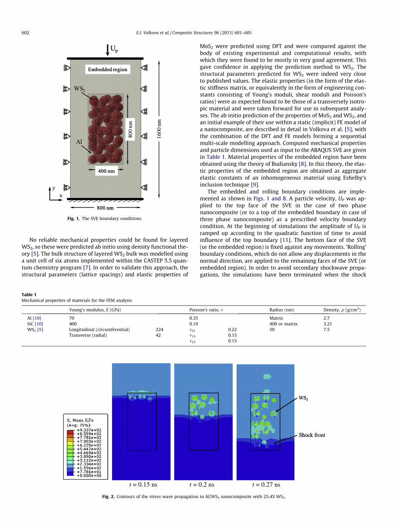
Fig. 1. The SVE boundary conditions.
602 E.I. Volkova et al. / Composite Structures 96 (2013) 601–605
No reliable mechanical properties could be found for layeredWS2, so these were predicted ab initio using density functional the-ory [5]. The bulk structure of layered WS2 bulk was modelled usinga unit cell of six atoms implemented within the CASTEP 5.5 quan-tum chemistry program [7]. In order to validate this approach, thestructural parameters (lattice spacings) and elastic properties of
Table 1Mechanical properties of materials for the FEM analysis.
Young’s modulus, E (GPa) Poiss
Al [10] 70 0.35SiC [10] 400 0.19WS2 [5] Longitudinal (circumferential) 224 m21
Transverse (radial) 42 m13
m23
t = 0.15 ns t =
Fig. 2. Contours of the stress wave propagation
MoS2 were predicted using DFT and were compared against thebody of existing experimental and computational results, withwhich they were found to be mostly in very good agreement. Thisgave confidence in applying the prediction method to WS2. Thestructural parameters predicted for WS2 were indeed very closeto published values. The elastic properties (in the form of the elas-tic stiffness matrix, or equivalently in the form of engineering con-stants consisting of Young’s moduli, shear moduli and Poisson’sratios) were as expected found to be those of a transversely isotro-pic material and were taken forward for use in subsequent analy-ses. The ab initio prediction of the properties of MoS2 and WS2, andan initial example of their use within a static (implicit) FE model ofa nanocomposite, are described in detail in Volkova et al. [5], withthe combination of the DFT and FE models forming a sequentialmulti-scale modelling approach. Computed mechanical propertiesand particle dimensions used as input to the ABAQUS SVE are givenin Table 1. Material properties of the embedded region have beenobtained using the theory of Budiansky [8]. In this theory, the elas-tic properties of the embedded region are obtained as aggregateelastic constants of an inhomogeneous material using Eshelby’sinclusion technique [9].
The embedded and rolling boundary conditions are imple-mented as shown in Figs. 1 and 8. A particle velocity, UP was ap-plied to the top face of the SVE in the case of two phasenanocomposite (or to a top of the embedded boundary in case ofthree phase nanocomposite) as a prescribed velocity boundarycondition. At the beginning of simulations the amplitude of UP isramped up according to the quadratic function of time to avoidinfluence of the top boundary [11]. The bottom face of the SVE(or the embedded region) is fixed against any movements. ‘Rolling’boundary conditions, which do not allow any displacements in thenormal direction, are applied to the remaining faces of the SVE (orembedded region). In order to avoid secondary shockwave propa-gations, the simulations have been terminated when the shock
on’s ratio, m Radius (nm) Density, q (g/cm3)
Matrix 2.7400 or matrix 3.21
0.22 50 7.50.150.15
0.2 ns t = 0.27 ns
in Al/WS2 nanocomposite with 25.4% WS2.

t = 0.14 ns t = 0.2 ns t = 0.27 ns
Fig. 3. Contours of the stress wave propagation in Al/WS2 nanocomposite with 13.2% WS2.
0
50
100
150
200
250
300
350
400
450
0 100 200 300 400 500 600 700 800 900
Stre
ss a
cros
s th
e SV
E, K
Pa
Distance, nm
Stress at 0.159 ns
Stress at 0.238 ns
Stress at 0.317 ns
Fig. 4. Averaged compression stress across the SVE for Al matrix with 25.4% IF-WS2
at time steps of 0.159 ns, 0.238 ns and 0.317 ns.
4700
4900
5100
5300
5500
0 5 10 15 20 25 30
US,
m/s
UP, mm/s
Fig. 5. Hugoniot data obtained from simulations. US–UP relations for the Al/WS2
nanocomposite (25.4% WS2). D is the acoustic wave speed through the equivalentaggregate material.
E.I. Volkova et al. / Composite Structures 96 (2013) 601–605 603
wave front has reached 90–95% of the SVE (embedded region)depth [11].
3. Results and discussion
3.1. Two phase nanocomposite
3.1.1. Shock wave propagation and dispersionThe wave propagation in the two phase nanocomposite
(25.4% WS2 in Al matrix) SVE model, with embedded boundaryconditions, is shown in Fig. 2. The stress in the y direction is shownat different time intervals. The shock wave shows some dispersionand stress variation behind the shock front as stress propagatesthrough the IF-WS2 faster than through the Al matrix resulting instress fingering. At reduced volume fraction (13.2% WS2), as shownin Fig. 3, this stress fingering is lower resulting in a more planarcompaction wave. Thus, the volume fraction of nanoparticle inclu-sions does affect the degree of dispersion.
Fig. 4 shows the average normal compression stress (y-stress)across the SVE at 100 nm intervals down the element at three time
steps for the 25.4% volume fraction case. This clearly shows theprogression of the shock front. It commences with a steep edgebut progressively slopes as dispersion of the wave front takesplace. Fig. 5 is a plot of the shock speed (US) vs. particle speed(UP) Hugoniot, obtained from a range of simulations at differentimpact (particle) speeds. As reported previously for other materialsystems [12], there is a linear relationship between US and UP andextrapolation back to zero UP gives a wave speed approximatelycorresponding to the acoustic wave speed (C0) of the system, indi-cated by the point at 4795 m/s on the axis. The latter has been cal-culated, corresponding to a material laterally restrained withrolling boundary conditions, from the following equation:
C0 ¼
ffiffiffiffiffiffiffiC11
q
s
where C11 is the component of the stiffness matrix of the aggregatematerial and q is the density as calculated for the embedding mate-rial. This agreement with the acoustic wave speed is confirmationthat the simulations are predicting shock propagation correctly.
3.1.2. Effect of mismatch of material properties: SiC/WS2 systemIt is instructive to explore what the effect of having a greater
mismatch between the moduli of the constituents as for the Al/WS2 system there is the close value for modulus of the aluminiummatrix (70 GPa) to the effective isotropic modulus of the WS2

Fig. 8. The SVE model for a 3 phase SiC/Al/WS2 nanocomposite.
Fig. 6. Normal stress wave propagation in nanocomposites: (a) Al/WS2 and (b) SiC/WS2.
1000
2000
3000
4000
5000
6000
7000
8000
9000
10000
0 5 10 15 20 25 30
US,
m/s
UP, mm/sAl/WS2
Acoustic speed for Al/WS2
SiC/WS2
Acoustic speed for SiC/WS2
Linear (Al/WS2)
Linear (SiC/WS2)
Fig. 7. Hugoniot data obtained from simulations. US–UP relations for Al/WS2 andSiC/WS2 nanocomposites and corresponding acoustic wave speeds.
604 E.I. Volkova et al. / Composite Structures 96 (2013) 601–605
inclusions, computed to be 60 GPa. A sensitivity study has there-fore been performed by setting the matrix to Silicon Carbide(SiC), i.e. compared with WS2 (60 GPa), matrix with a high modulus(400 GPa). Note that this system does not represent real materialbut is used purely for illustration purposes within the sensitivitystudy. The result of the simulation, when the shock wave has tra-versed half of the SVE length, is compared with the Al/WS2 systemin Fig. 6. The SiC/WS2 system shows significant stress variationindicative of dispersion, with stresses in this case, as expected, verymuch higher in the stiff SiC matrix than in the inclusions. For thissystem, the mismatch of moduli is 400 GPa/60 GPa � 7. Stress fin-gering at the shock front is more pronounced than the Al/WS2 sys-tem. In general, it can be concluded that a greater mismatch ofmoduli between matrix and inclusions results in a greater degreeof dispersion as evidenced by stress fingering and/or stressvariations.
Fig. 7 shows that both systems exhibit the expected US–UP
Hugoniot linear relationships, extrapolating back to the acoustic
wavespeeds. The SiC/WS2 system exhibits the highest shock speedsdue to its higher effective modulus.
3.2. Three phase nanocomposite
An SVE model for a three-phase system has also been studied.The system comprises SiC/Al composite (26.8% SiC), reinforcedwith 8.75% IF-WS2 nano inclusions as shown in Fig. 8. This is rep-resentative of a typical armour material (SiC/Al) but reinforcedwith hard nano inclusions. The micro scale ceramic particle isembedded in the Al matrix and surrounded with a random distri-bution of the nano scale WS2 inclusions. To simplify the analysis,rolling boundary conditions are applied directly to the compositeregion rather than embedding it in an isotropic buffer zone. A par-ticle velocity has also been applied directly to the SVE cell. As in thecase of two phase nanocomposite the bottom face of the SVE isfixed. Previous analysis of the two-phase systems has shown thatthese boundary conditions give similar results to the embedded

t = 0.10 ns t = 0.14 ns t = 0.16 ns(a) (b) (c)
Fig. 9. Stress wave propagation in a SiC/Al/WS2 nanocomposite.
1000
2000
3000
4000
5000
6000
7000
8000
9000
10000
0 5 10 15 20 25
US,
m/s
UP, mm/s
SiC/Al/WS2
Acoustic speed for SiC/Al/WS2
Linear (SiC/Al/WS2)
Fig. 10. Hugoniot data obtained from simulations. US–UP relations for theSiC/Al/WS2 nanocomposite (26.8% SiC and 8.75% WS2). } is the acoustic wavespeed through the equivalent aggregate material.
E.I. Volkova et al. / Composite Structures 96 (2013) 601–605 605
boundary conditions, in spite of the greater constraint against locallateral displacements.
The wave propagation through the three phase nanocompositeis shown in Fig. 9. The stress in the y direction is shown propagat-ing through the material at three points in time. It is clear that thewave has a high propagation speed through the ceramic particleextending the wave front in this region. This is effectively stressfingering, but on a micro scale rather than a nano scale. In addition,the nano inclusions do have some dispersive effect at the wavefront. As for the two-phase systems, Hugoniot data in for the formof a US vs. UP plot can also be generated from this model by impact-ing at different speeds, as shown in Fig. 10.
4. Conclusion
It has been shown that a statistical volume element (SVE)approach in an elastic FE analysis can model the dynamic responseof a two and three-phase nanocomposite in some detail. The
simulation of shock wave progression through the SVE has shownevidence of stress fingering and dispersion caused by the nanoinclusions and that these effects are influenced by volume fractionof inclusions and mismatch of constituent stiffnesses, i.e. moduli. Agreater mismatch results in greater dispersion of the wave front.Shock speed vs. particle speed Hugoniot data has also been gener-ated from the models. Successful simulation of the shock wavepropagation and comparisons with the value(s) of the acousticwave speed provide the confidence that the numerical techniqueis suitable for more complex and realistic simulations includingimplementation of failure mechanisms. This will be necessary tofully simulate the material response under very high rates of load-ing such as that occurring during blast and ballistic conditions.
Acknowledgements
The authors are grateful to the Engineering and Physical Re-search Council for funding this project under Grant EP/G039879/2 (co-funded by the Ministry of Defence (MoD) under the Joint Aca-demic Research Programme for Defence) and for funding E. Bich-outskaia’s position via a EPSRC Career Acceleration FellowshipEP/G005060/1, and to the University of Nottingham for co-fundingthe studentship of E.I. Volkova. We are also grateful to Professor G.Seifert for fruitful and constructive discussions.
References
[1] Rapoport L, Lvovsky M, Lapsker I, Leshchinsky V, Volovik Yu, Feldman Y, et al.NanoLett 2001;1:137.
[2] Zhu YQ, Sekine T, Li YH, Wang WX, Fay MW, Edwards H, et al. Adv Mater2005;17:1500.
[3] Zhu YQ, Sekine T, Li YH, Fay MW, Zhao YM, Patrick Poa CH, et al. J Am Chem Soc2005;126:16253.
[4] Zhu YQ, Sekine T, Brigatti KS, Firth S, Tenne R, Rosentsveig R, et al. J Am ChemSoc 2003;127:1329.
[5] Volkova EI, Jones IA, Brooks R, Zhu Y, Bichoutskaia E. Phys Rev B, in press.[6] Tenne R, Homyonfer M, Feldman Y. Chem Mater 1998;10:11.[7] Clark SJ, Segall MD, Pickard CJ, Hasnip PJ, Probert MIJ, Refson K, et al. Z
Kristallogr 2005;220:567.[8] Budiansky B. J Mech Phys Solids 1965;13:223.[9] Eshelby JD. Proceed Royal Soc A 1957;241:376.
[10] Callister WD, Rethwisch DG. Material science and engineering: anintroduction. Wiley; 2010.
[11] Austin RA, McDowell DL, Benson DJ. Modelling Simul Mater Sci Eng2006;14:537.
[12] Davison L. Fundamentals of shock wave propagation in solids. Springer; 2008.