mestek outdoor rooftop evaporative cooling units...operate, or service the evaporative cooling unit....
TRANSCRIPT

SSAAFFEETTYY WWAARRNNIINNGGOnly qualified personnel should install and service the equipment. The installation, starting up, and servicing of heating, ventilating, andair-conditioning equipment can be hazardous and requires specific knowledge and training. Improperly installed, adjusted or alteredequipment by an unqualified person could result in death or serious injury. When working on the equipment, observe all precautions in theliterature and on the tags, stickers, and labels that are attached to the equipment.
March 2017 MMUUAA--SSVVXX000022AA--EENN
Outdoor Rooftop Evaporative Cooling UnitsFor Heating, Cooling, and Ventilating Systems
FPO
Installation, Operation,and Maintenance
©2017 Ingersoll Rand All rights reserved MUA-SVX002A-EN
IntroductionRead this manual thoroughly before operating or servicing this unit.
If this unit is to be mated with a makeup air heating unit, be sure to read all applicable manuals,submittal/data sheets and all labels associated with the heating unit before attempting to install,operate, or service the Evaporative Cooling unit.
Warnings, Cautions, and NoticesSafety advisories appear throughout this manual as required. Your personal safety and theproper operation of this machine depend upon the strict observance of these precautions.
The three types of advisories are defined as follows:
Indicates a potentially hazardous situation which, if not avoided, could result indeath or serious injury.
Indicates a potentially hazardous situation which, if not avoided, could result inminor or moderate injury. It could also be used to alert against unsafe practices.
Indicates a situation that could result in equipment or property-damage onlyaccidents.
Important Environmental ConcernsScientific research has shown that certain man-made chemicals can affect the earth’s naturallyoccurring stratospheric ozone layer when released to the atmosphere. In particular, several of theidentified chemicals that may affect the ozone layer are refrigerants that contain Chlorine,Fluorine and Carbon (CFCs) and those containing Hydrogen, Chlorine, Fluorine and Carbon(HCFCs). Not all refrigerants containing these compounds have the same potential impact to theenvironment. Trane advocates the responsible handling of all refrigerants-including industryreplacements for CFCs and HCFCs such as saturated or unsaturated HFCs and HCFCs.
Important Responsible Refrigerant PracticesTrane believes that responsible refrigerant practices are important to the environment, ourcustomers, and the air conditioning industry. All technicians who handle refrigerants must becertified. The Federal Clean Air Act (Section 608) sets forth the requirements for handling,reclaiming, recovering and recycling of certain refrigerants and the equipment that is used inthese service procedures. In addition, some states or municipalities may have additionalrequirements that must also be adhered to for responsible management of refrigerants. Knowthe applicable laws and follow them.
WWAARRNNIINNGGPPrrooppeerr FFiieelldd WWiirriinngg aanndd GGrroouunnddiinngg RReeqquuiirreedd!!FFaaiilluurree ttoo ffoollllooww ccooddee ccoouulldd rreessuulltt iinn ddeeaatthh oorr sseerriioouuss iinnjjuurryy..AAllll ffiieelldd wwiirriinngg MMUUSSTT bbee ppeerrffoorrmmeedd bbyy qquuaalliiffiieedd ppeerrssoonnnneell.. IImmpprrooppeerrllyy iinnssttaalllleedd aannddggrroouunnddeedd ffiieelldd wwiirriinngg ppoosseess FFIIRREE aanndd EELLEECCTTRROOCCUUTTIIOONN hhaazzaarrddss.. TToo aavvooiidd tthheessee hhaazzaarrddss,,yyoouu MMUUSSTT ffoollllooww rreeqquuiirreemmeennttss ffoorr ffiieelldd wwiirriinngg iinnssttaallllaattiioonn aanndd ggrroouunnddiinngg aass ddeessccrriibbeedd iinnNNEECC aanndd yyoouurr llooccaall//ssttaattee//nnaattiioonnaall eelleeccttrriiccaall ccooddeess..
MUA-SVX002A-EN 3
WWAARRNNIINNGGPPeerrssoonnaall PPrrootteeccttiivvee EEqquuiippmmeenntt ((PPPPEE)) RReeqquuiirreedd!!FFaaiilluurree ttoo wweeaarr pprrooppeerr PPPPEE ffoorr tthhee jjoobb bbeeiinngg uunnddeerrttaakkeenn ccoouulldd rreessuulltt iinn ddeeaatthh oorr sseerriioouussiinnjjuurryy..TTeecchhnniicciiaannss,, iinn oorrddeerr ttoo pprrootteecctt tthheemmsseellvveess ffrroomm ppootteennttiiaall eelleeccttrriiccaall,, mmeecchhaanniiccaall,, aannddcchheemmiiccaall hhaazzaarrddss,, MMUUSSTT ffoollllooww pprreeccaauuttiioonnss iinn tthhiiss mmaannuuaall aanndd oonn tthhee ttaaggss,, ssttiicckkeerrss,, aannddllaabbeellss,, aass wweellll aass tthhee iinnssttrruuccttiioonnss bbeellooww::
•• BBeeffoorree iinnssttaalllliinngg//sseerrvviicciinngg tthhiiss uunniitt,, tteecchhnniicciiaannss MMUUSSTT ppuutt oonn aallll PPPPEE rreeqquuiirreedd ffoorrtthhee wwoorrkk bbeeiinngg uunnddeerrttaakkeenn ((EExxaammpplleess;; ccuutt rreessiissttaanntt gglloovveess//sslleeeevveess,, bbuuttyyll gglloovveess,,ssaaffeettyy ggllaasssseess,, hhaarrdd hhaatt//bbuummpp ccaapp,, ffaallll pprrootteeccttiioonn,, eelleeccttrriiccaall PPPPEE aanndd aarrcc ffllaasshhccllootthhiinngg)).. AALLWWAAYYSS rreeffeerr ttoo aapppprroopprriiaattee MMaatteerriiaall SSaaffeettyy DDaattaa SShheeeettss ((MMSSDDSS))//SSaaffeettyyDDaattaa SShheeeettss ((SSDDSS)) aanndd OOSSHHAA gguuiiddeelliinneess ffoorr pprrooppeerr PPPPEE..
•• WWhheenn wwoorrkkiinngg wwiitthh oorr aarroouunndd hhaazzaarrddoouuss cchheemmiiccaallss,, AALLWWAAYYSS rreeffeerr ttoo tthheeaapppprroopprriiaattee MMSSDDSS//SSDDSS aanndd OOSSHHAA//GGHHSS ((GGlloobbaall HHaarrmmoonniizzeedd SSyysstteemm ooffCCllaassssiiffiiccaattiioonn aanndd LLaabbeelllliinngg ooff CChheemmiiccaallss)) gguuiiddeelliinneess ffoorr iinnffoorrmmaattiioonn oonn aalllloowwaabblleeppeerrssoonnaall eexxppoossuurree lleevveellss,, pprrooppeerr rreessppiirraattoorryy pprrootteeccttiioonn aanndd hhaannddlliinngg iinnssttrruuccttiioonnss..
•• IIff tthheerree iiss aa rriisskk ooff eenneerrggiizzeedd eelleeccttrriiccaall ccoonnttaacctt,, aarrcc,, oorr ffllaasshh,, tteecchhnniicciiaannss MMUUSSTT ppuuttoonn aallll PPPPEE iinn aaccccoorrddaannccee wwiitthh OOSSHHAA,, NNFFPPAA 7700EE,, oorr ootthheerr ccoouunnttrryy--ssppeecciiffiiccrreeqquuiirreemmeennttss ffoorr aarrcc ffllaasshh pprrootteeccttiioonn,, PPRRIIOORR ttoo sseerrvviicciinngg tthhee uunniitt.. NNEEVVEERR PPEERRFFOORRMMAANNYY SSWWIITTCCHHIINNGG,, DDIISSCCOONNNNEECCTTIINNGG,, OORR VVOOLLTTAAGGEE TTEESSTTIINNGG WWIITTHHOOUUTT PPRROOPPEERREELLEECCTTRRIICCAALL PPPPEE AANNDD AARRCC FFLLAASSHH CCLLOOTTHHIINNGG.. EENNSSUURREE EELLEECCTTRRIICCAALL MMEETTEERRSS AANNDDEEQQUUIIPPMMEENNTT AARREE PPRROOPPEERRLLYY RRAATTEEDD FFOORR IINNTTEENNDDEEDD VVOOLLTTAAGGEE..
WWAARRNNIINNGGRRiisskk ooff IIllllnneessss!!FFaaiilluurree ttoo ffoollllooww iinnssttrruuccttiioonnss bbeellooww ccoouulldd rreessuulltt iinn sseevveerree iillllnneessss..MMaaiinnttaaiinn wwaatteerr iinn ssuummppss bbyy pprrooppeerr mmiiccrroobbiicciiddaall wwaatteerr ttrreeaattmmeenntt ttoo mmiinniimmiizzee tthhee rriisskkss ooffiillllnneessss ccaauusseedd bbyy LLeeggiioonneellllaa PPnneeuummoopphhiillaa ((tthhee bbaacctteerriiaa tthhaatt ccaauusseess LLeeggiioonnnnaaiirree''ssDDiisseeaassee)) aanndd ootthheerr bbaacctteerriiaa.. RReeffeerr ttoo llooccaall ccooddeess rreeggaarrddiinngg aannyy aaddddiittiioonnaall ttrreeaattmmeenntt oorrrreessttrriiccttiioonnss rreeggaarrddiinngg wwaatteerr ssuupppplliieess aanndd uussaaggee..
CopyrightThis document and the information in it are the property of Trane, and may not be used orreproduced in whole or in part without written permission. Trane reserves the right to revise thispublication at any time, and to make changes to its content without obligation to notify anyperson of such revision or change.
TrademarksAll trademarks referenced in this document are the trademarks of their respective owners.
IInnttrroodduuccttiioonn
4 MUA-SVX002A-EN
Receiving Instructions . . . . . . . . . . . . . . . . . . . . . . . . . . . . . . . . . . . . . . . . . . . . . . . . . . . . . . . . . 5
General Safety Information . . . . . . . . . . . . . . . . . . . . . . . . . . . . . . . . . . . . . . . . . . . . . . . . . . . . 6
Performance and Specification Data . . . . . . . . . . . . . . . . . . . . . . . . . . . . . . . . . . . . . . . . . . . 7
Evaporative Cooler Parts and Identification . . . . . . . . . . . . . . . . . . . . . . . . . . . . . . . . . . . 12
Installation. . . . . . . . . . . . . . . . . . . . . . . . . . . . . . . . . . . . . . . . . . . . . . . . . . . . . . . . . . . . . . . . . . . . 13Mounting to Roof . . . . . . . . . . . . . . . . . . . . . . . . . . . . . . . . . . . . . . . . . . . . . . . . . . . . . . . . . . . 13
Connecting the Water Supply . . . . . . . . . . . . . . . . . . . . . . . . . . . . . . . . . . . . . . . . . . . . . . . . 13
Faucet Use . . . . . . . . . . . . . . . . . . . . . . . . . . . . . . . . . . . . . . . . . . . . . . . . . . . . . . . . . . . . . . . . . 14
Adjusting the Water Level and Float Valve . . . . . . . . . . . . . . . . . . . . . . . . . . . . . . . . . . . . 14
Adjusting the Water Flow. . . . . . . . . . . . . . . . . . . . . . . . . . . . . . . . . . . . . . . . . . . . . . . . . . . . 15
Bleed-Off. . . . . . . . . . . . . . . . . . . . . . . . . . . . . . . . . . . . . . . . . . . . . . . . . . . . . . . . . . . . . . . . . . . 15
Adjusting the Bleed-Off. . . . . . . . . . . . . . . . . . . . . . . . . . . . . . . . . . . . . . . . . . . . . . . . . . . . . . 15
Electrical Connections . . . . . . . . . . . . . . . . . . . . . . . . . . . . . . . . . . . . . . . . . . . . . . . . . . . . . . . . 16Optional Fill and Drain Kit . . . . . . . . . . . . . . . . . . . . . . . . . . . . . . . . . . . . . . . . . . . . . . . . . . . 17
Grounding . . . . . . . . . . . . . . . . . . . . . . . . . . . . . . . . . . . . . . . . . . . . . . . . . . . . . . . . . . . . . . . . . 17
Wiring Diagrams. . . . . . . . . . . . . . . . . . . . . . . . . . . . . . . . . . . . . . . . . . . . . . . . . . . . . . . . . . . . 17
Maintenance. . . . . . . . . . . . . . . . . . . . . . . . . . . . . . . . . . . . . . . . . . . . . . . . . . . . . . . . . . . . . . . . . . 19Maintenance Schedule . . . . . . . . . . . . . . . . . . . . . . . . . . . . . . . . . . . . . . . . . . . . . . . . . . . . . . 20
Changing the Media. . . . . . . . . . . . . . . . . . . . . . . . . . . . . . . . . . . . . . . . . . . . . . . . . . . . . . . . . 20
Cleaning the Water Pump . . . . . . . . . . . . . . . . . . . . . . . . . . . . . . . . . . . . . . . . . . . . . . . . . . . 21
Washing the Media . . . . . . . . . . . . . . . . . . . . . . . . . . . . . . . . . . . . . . . . . . . . . . . . . . . . . . . . . 21
Washing the Inlet Filter . . . . . . . . . . . . . . . . . . . . . . . . . . . . . . . . . . . . . . . . . . . . . . . . . . . . . . 21
Cabinet Cleaning and Touch-Up. . . . . . . . . . . . . . . . . . . . . . . . . . . . . . . . . . . . . . . . . . . . . . 22
Winter Shut Down . . . . . . . . . . . . . . . . . . . . . . . . . . . . . . . . . . . . . . . . . . . . . . . . . . . . . . . . . . 22
Roof Curb Kit — Part Number 0134-0212-01* . . . . . . . . . . . . . . . . . . . . . . . . . . . . . . . . . 23
Table of Contents

MUA-SVX002A-EN 5
Receiving Instructions
Inspect shipment immediately after receiving to determine if any damage has occurred duringshipment If any damage is found, the consignee should sign the bill of lading, indicating suchdamage, and immediately file claim for damage with the transportation company.
NNoottee:: This equipment has been tested and inspected. It has been shipped free from defects fromour factory. However, during shipment and installation, problems such as loose wires,leaks or loose fasteners may occur. It is the installer's responsibility to inspect and correctany problems that may be found.
6 MUA-SVX002A-EN
General Safety Information
WWAARRNNIINNGGHHaazzaarrddoouuss SSeerrvviiccee PPrroocceedduurreess!!FFaaiilluurree ttoo ffoollllooww aallll pprreeccaauuttiioonnss iinn tthhiiss mmaannuuaall aanndd oonn tthhee ttaaggss,, ssttiicckkeerrss,, aanndd llaabbeellss ccoouullddrreessuulltt iinn ddeeaatthh oorr sseerriioouuss iinnjjuurryy..TTeecchhnniicciiaannss,, iinn oorrddeerr ttoo pprrootteecctt tthheemmsseellvveess ffrroomm ppootteennttiiaall eelleeccttrriiccaall,, mmeecchhaanniiccaall,, aannddcchheemmiiccaall hhaazzaarrddss,, MMUUSSTT ffoollllooww pprreeccaauuttiioonnss iinn tthhiiss mmaannuuaall aanndd oonn tthhee ttaaggss,, ssttiicckkeerrss,, aannddllaabbeellss,, aass wweellll aass tthhee ffoolllloowwiinngg iinnssttrruuccttiioonnss:: UUnnlleessss ssppeecciiffiieedd ootthheerrwwiissee,, ddiissccoonnnneecctt aalllleelleeccttrriiccaall ppoowweerr iinncclluuddiinngg rreemmoottee ddiissccoonnnneecctt aanndd ddiisscchhaarrggee aallll eenneerrggyy ssttoorriinngg ddeevviicceessssuucchh aass ccaappaacciittoorrss bbeeffoorree sseerrvviicciinngg.. FFoollllooww pprrooppeerr lloocckkoouutt//ttaaggoouutt pprroocceedduurreess ttoo eennssuurreetthhee ppoowweerr ccaann nnoott bbee iinnaaddvveerrtteennttllyy eenneerrggiizzeedd.. WWhheenn nneecceessssaarryy ttoo wwoorrkk wwiitthh lliivvee eelleeccttrriiccaallccoommppoonneennttss,, hhaavvee aa qquuaalliiffiieedd lliicceennsseedd eelleeccttrriicciiaann oorr ootthheerr iinnddiivviidduuaall wwhhoo hhaass bbeeeennttrraaiinneedd iinn hhaannddlliinngg lliivvee eelleeccttrriiccaall ccoommppoonneennttss ppeerrffoorrmm tthheessee ttaasskkss..
Unless otherwise specified, the following conversions may be used for calculating SI unitmeasurements:
• 1 inch = 25.4 mm
• 1 foot = 0.305 m
• 1 gallon = 3.785 L
• 1 pound = 0.454 kg
• 1 psig = 6.894 kPa
• 1 cubic foot = 0.028 m3
• 1000 Btu/Cu. Ft. = 37.5 MJ/m3
• 1000 Btu per hour = 0.293 kW
• 1 inch water column = 0.249 kPa
• liter/second = CFM x 0.472
• meter/second = FPM ÷ 196.8
MUA-SVX002A-EN 7
Performance and Specification Data
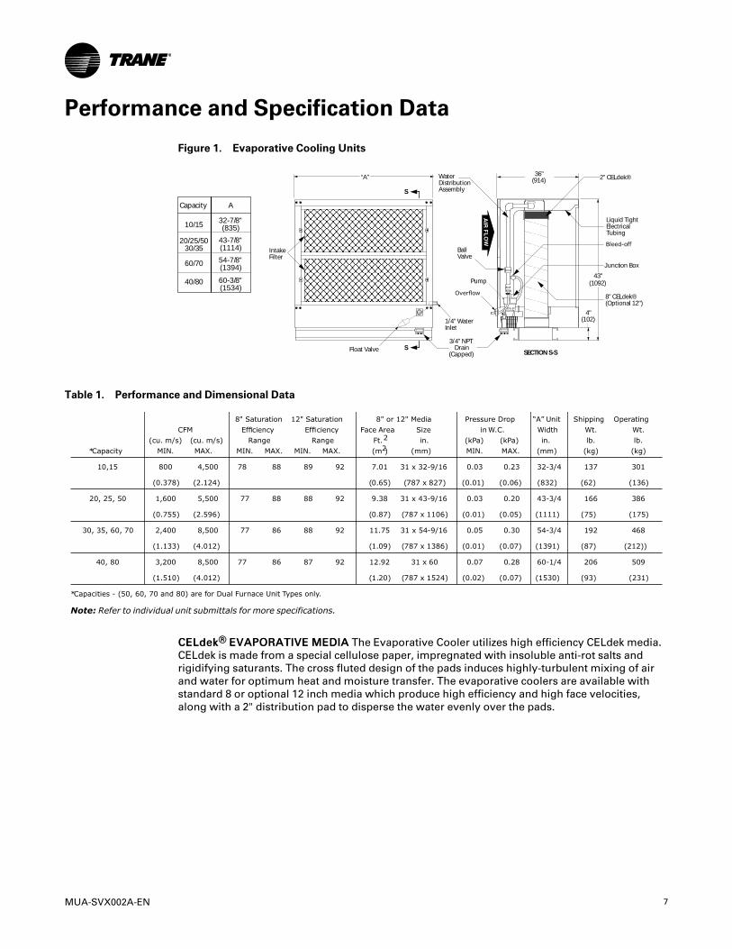
Figure 1. Evaporative Cooling Units
4"(102)
8" CELdek®(Optional 12")
2" CELdek®
Pump
BallValve
1/4" WaterInlet
Float Valve
WaterDistributionAssembly
“A”
IntakeFilter
S
S
SECTION S-S
3/4" NPTDrain
(Capped)
Junction Box
Liquid TightElectricalTubing
43"(1092)
36"(914)
A
32-7/8"(835)
43-7/8"(1114)
54-7/8"(1394)
60-3/8"(1534)
Capacity
10/15
20/25/5030/35
60/70
40/80
Table 1. Performance and Dimensional Data
Note: Refer to individual unit submittals for more specifications.
CCEELLddeekk®® EEVVAAPPOORRAATTIIVVEE MMEEDDIIAA The Evaporative Cooler utilizes high efficiency CELdek media.CELdek is made from a special cellulose paper, impregnated with insoluble anti-rot salts andrigidifying saturants. The cross fluted design of the pads induces highly-turbulent mixing of airand water for optimum heat and moisture transfer. The evaporative coolers are available withstandard 8 or optional 12 inch media which produce high efficiency and high face velocities,along with a 2" distribution pad to disperse the water evenly over the pads.

8 MUA-SVX002A-EN
Figure 2. Pressure Drop and Evaporative Cooling Efficiency
200
0.5100%
90%
80%
70%
60%
0.4
0.3
0.2
0.1
Air Velocity - FPM
ycneiciffE gnil oo
C evit ar opavE
GW - sehcnI por
D er usserP ri
A
300 400 500 600 700 800
12"
8"
8"
12"
Air Pressu
re Drop
Figure 3. Natural Vent Rooftop Unit with Evaporative Cooler (without Supply Plenum)
BDischargeOpening
1-5/16" (33) Typ.Anchor HoleLocation
5"(127)
A
C (Typ. Sq.)
*F
D
39"(991)
GOutside
1" (25)Curb Cap
5/8" (16) Typ.Anchor HoleLocation
6-1/16"(154)
8-3/4(222)
26"(660)
ElectricalConnections
Vent CapsAre ShippedIn SeparateCartons
GasConnection
§ L
EvaporativeCooler
18-7/8" (479)
O.S. Damperx J Typ.
Opening
6-1/2"(165)
CL
1-1/8" (29)Typ. Duct
Flange
1" (25)Typ.
19"(483)
DischargeOpening
10-1/8"(257)
§ U (Capacities 10/40)
§ U (Capacities 50/80)"63 "63)419( )419(
Table 2. Dimensions for Natural Vent Rooftop Unit with Evaporative Cooling (without SupplyPlenum)
PPeerrffoorrmmaannccee aanndd SSppeecciiffiiccaattiioonn DDaattaa
MUA-SVX002A-EN 9
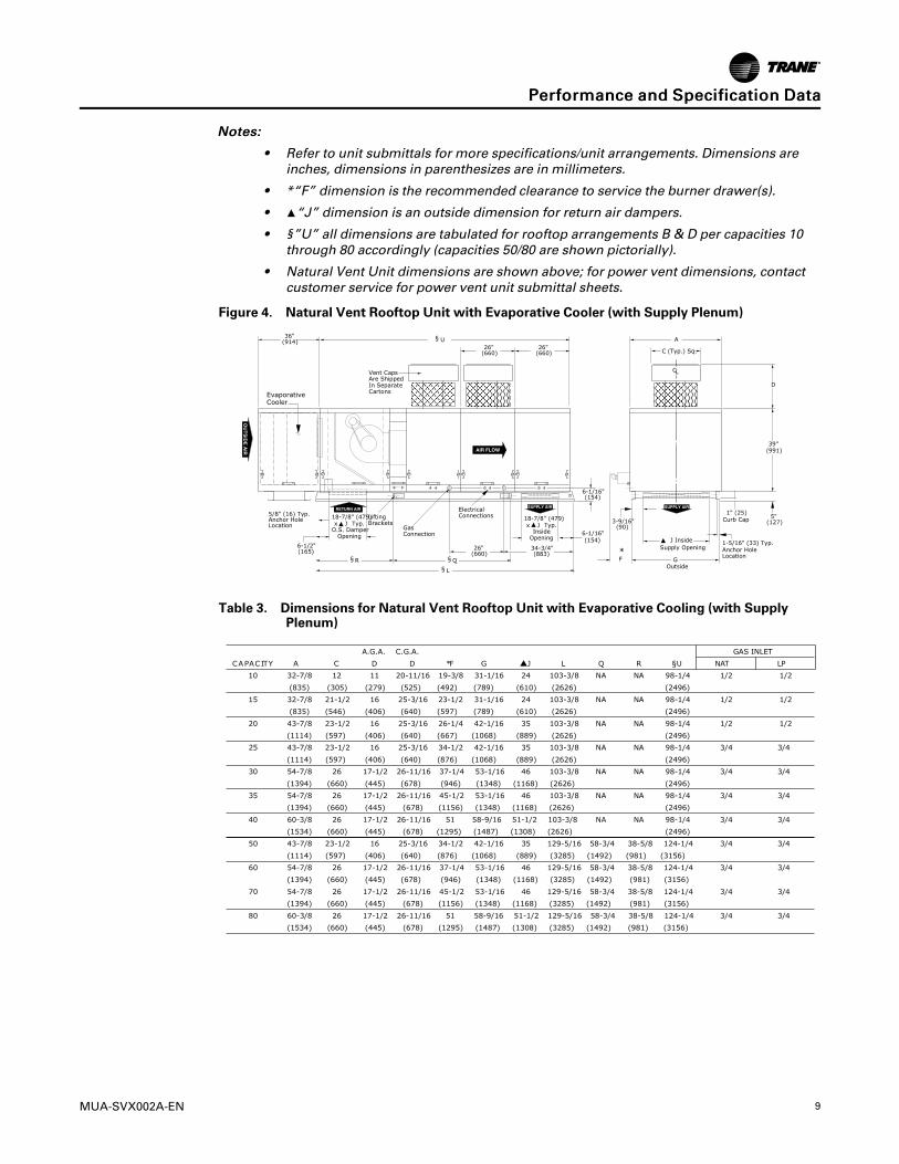
NNootteess::
• Refer to unit submittals for more specifications/unit arrangements. Dimensions areinches, dimensions in parenthesizes are in millimeters.
• *“F” dimension is the recommended clearance to service the burner drawer(s).
• ▲“J” dimension is an outside dimension for return air dampers.
• §”U” all dimensions are tabulated for rooftop arrangements B & D per capacities 10through 80 accordingly (capacities 50/80 are shown pictorially).
• Natural Vent Unit dimensions are shown above; for power vent dimensions, contactcustomer service for power vent unit submittal sheets.
Figure 4. Natural Vent Rooftop Unit with Evaporative Cooler (with Supply Plenum)
Table 3. Dimensions for Natural Vent Rooftop Unit with Evaporative Cooling (with SupplyPlenum)
PPeerrffoorrmmaannccee aanndd SSppeecciiffiiccaattiioonn DDaattaa
10 MUA-SVX002A-EN
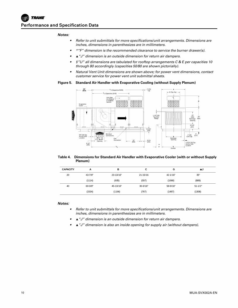
NNootteess::
• Refer to unit submittals for more specifications/unit arrangements. Dimensions areinches, dimensions in parenthesizes are in millimeters.
• *“F” dimension is the recommended clearance to service the burner drawer(s).
• ▲“J” dimension is an outside dimension for return air dampers.
• §”U” all dimensions are tabulated for rooftop arrangements C & E per capacities 10through 80 accordingly (capacities 50/80 are shown pictorially).
• Natural Vent Unit dimensions are shown above; for power vent dimensions, contactcustomer service for power vent unit submittal sheets.
Figure 5. Standard Air Handler with Evaporative Cooling (without Supply Plenum)
BDischargeOpening
1-5/16" (33) Typ.Anchor HoleLocation
5"(127)
A
C (Typ. Sq.)
*F
D
39"(991)
GOutside
1" (25)Curb Cap
5/8" (16) Typ.Anchor HoleLocation
6-1/16"(154)
8-3/4(222)
26"(660)
ElectricalConnections
Vent CapsAre ShippedIn SeparateCartons
GasConnection
§ L
EvaporativeCooler
18-7/8" (479)
O.S. Damperx J Typ.
Opening
6-1/2"(165)
CL
1-1/8" (29)Typ. Duct
Flange
1" (25)Typ.
19"(483)
DischargeOpening
10-1/8"(257)
§ U (Capacities 10/40)
§ U (Capacities 50/80)"63 "63)419( )419(
Table 4. Dimensions for Standard Air Handler with Evaporative Cooler (with or without SupplyPlenum)
G C B A YTICAPAC J
20 43-7/8" 23-13/16" 21-15/16 42-1/16" 35"
(1114) (605) (557) (1068) (889)
40 60-3/8" 45-13/16" 30-3/16" 58-9/16" 51-1/2"
(1534) (1164) (767) (1487) (1308)
NNootteess::
• Refer to unit submittals for more specifications/unit arrangements. Dimensions areinches, dimensions in parenthesizes are in millimeters.
• ▲“J” dimension is an outside dimension for return air dampers.
• ▲“J” dimension is also an inside opening for supply air (without dampers).
PPeerrffoorrmmaannccee aanndd SSppeecciiffiiccaattiioonn DDaattaa
MUA-SVX002A-EN 11
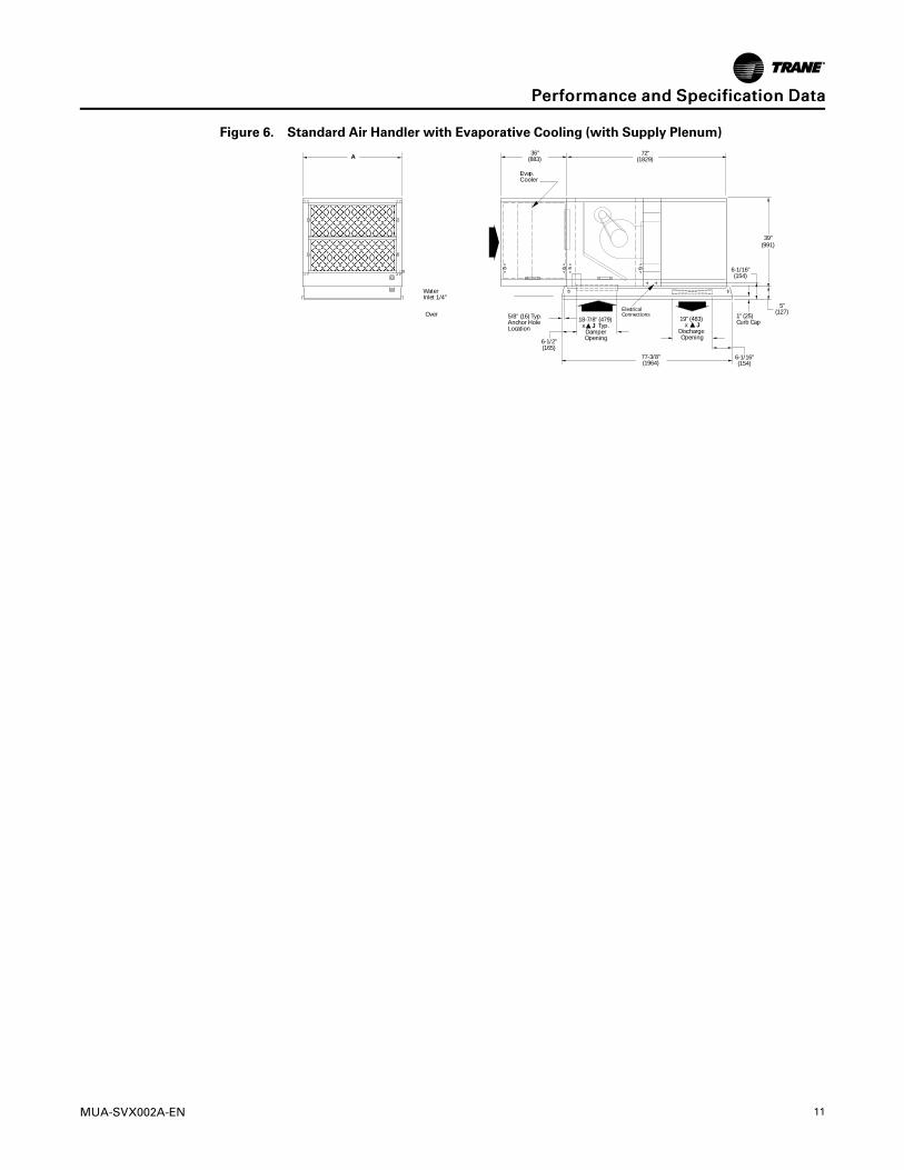
Figure 6. Standard Air Handler with Evaporative Cooling (with Supply Plenum)
18-7/8" (479)x J Typ.DamperOpening
39"(991)
5"(127)
1" (25)Curb Cap
6-1/16"(154)
5/8" (16) Typ.Anchor HoleLocation
72"(1829)
77-3/8"(1964)
6-1/2"(165)
36"(883)
ElectricalConnections
Evap.Cooler
19" (483)x J
DischargeOpening
6-1/16"(154)
A
WaterInlet 1/4"
Over! ow3/4" NPT Drain(Capped)
IntakeFilter
D3667BT3672FR
PPeerrffoorrmmaannccee aanndd SSppeecciiffiiccaattiioonn DDaattaa
12 MUA-SVX002A-EN
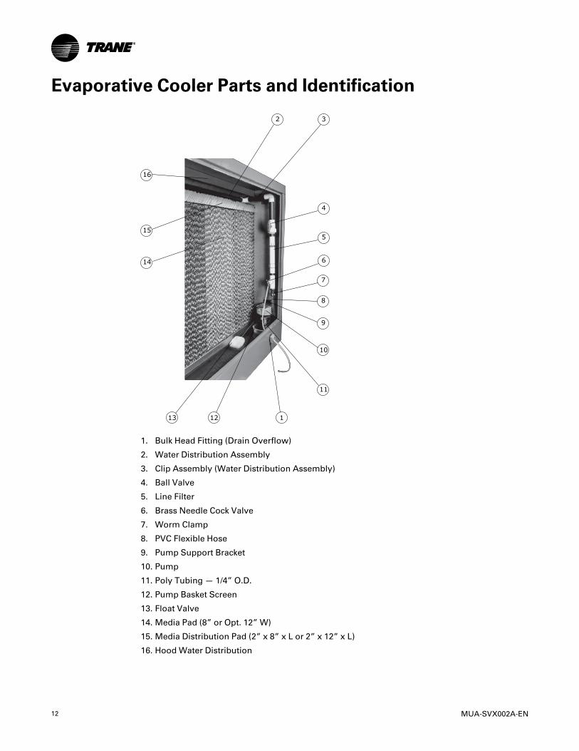
Evaporative Cooler Parts and Identification
1. Bulk Head Fitting (Drain Overflow)
2. Water Distribution Assembly
3. Clip Assembly (Water Distribution Assembly)
4. Ball Valve
5. Line Filter
6. Brass Needle Cock Valve
7. Worm Clamp
8. PVC Flexible Hose
9. Pump Support Bracket
10. Pump
11. Poly Tubing — 1/4” O.D.
12. Pump Basket Screen
13. Float Valve
14. Media Pad (8” or Opt. 12” W)
15. Media Distribution Pad (2” x 8” x L or 2” x 12” x L)
16. Hood Water Distribution

MUA-SVX002A-EN 13
InstallationNNoottee:: This manual is for Evaporative Cooler Module Installations only. Refer to the Installation
and Service Manuals for Rooftop Packaged Units and Outdoor Furnaces for these unitinstallations.
WWAARRNNIINNGGMMoouunnttiinngg IInntteeggrriittyy!!FFaaiilluurree ttoo ffoollllooww iinnssttrruuccttiioonn bbeellooww ccoouulldd rreessuulltt iinn ddeeaatthh oorr sseerriioouuss iinnjjuurryy oorr ppoossssiibblleeeeqquuiippmmeenntt oorr pprrooppeerrttyy--oonnllyy ddaammaaggee..EEnnssuurree tthhee rrooooff ssttrruuccttuurree ssuuppppoorrttss aarree ssttrroonngg eennoouugghh ttoo ssuuppppoorrtt tthhee wweeiigghhtt ooff tthhee uunniittaanndd aannyy aacccceessssoorriieess..
Mounting to Roof1. Before positioning the unit in its permanent location, make certain that the roof is capable of
carrying the load of this equipment. Note that when the cooler is filled with water, the unitwill be much heavier than when dry. See “Performance and Dimension Data” table forappropriate operating weight.
2. If unit is to be mounted on a curb, refer to the curb specifications for installationrequirements.
3. Make certain that the mounting surface is level in all directions.
4. Make certain that you have sufficient means for lifting the unit into place.
5. Installation must conform to local and national building and safety codes.
6. The units are mounted on skid rails and are suitable for use on combustible flooring. It isrecommended that the skids be mounted either on solid planking or on steel channels, butnever on a soft tar roof where the skids could sink and reduce the 4" clearance between thebottom pan and the roof.
7. Inspect all internal parts of the cooler section to determine if any damage has occurred duringshipment. See roof curb specifications at the end of the manual.
Connecting the Water SupplyNNOOTTIICCEE
CCoooolleerr DDaammaaggee!!FFaaiilluurree ttoo ffoollllooww iinnssttrruuccttiioonn bbeellooww ccoouulldd rreessuulltt iinn ccoooolleerr ddaammaaggee ffrroomm ccoorrrroossiioonn..DDoo nnoott aattttaacchh ssoofftt wwaatteerr eeqquuiippmmeenntt ttoo wwaatteerr lliinneess ggooiinngg ttoo tthhee ccoooolleerr..
1. A water valve should be installed at a convenient location to allow water to be turned on andoff. Use 1/4" tubing to supply water to Evaporative Cooler. A water connector kit is availableat your local wholesaler.
2. Place tube nut and ferrule over the end of the tubing.
3. Insert tubing into factory-installed float valve and tighten securely.
14 MUA-SVX002A-EN
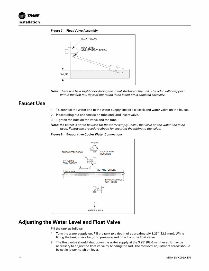
Figure 7. Float Valve Assembly
NNoottee:: There will be a slight odor during the initial start-up of the unit. The odor will disappearwithin the first few days of operation if the bleed-off is adjusted correctly.
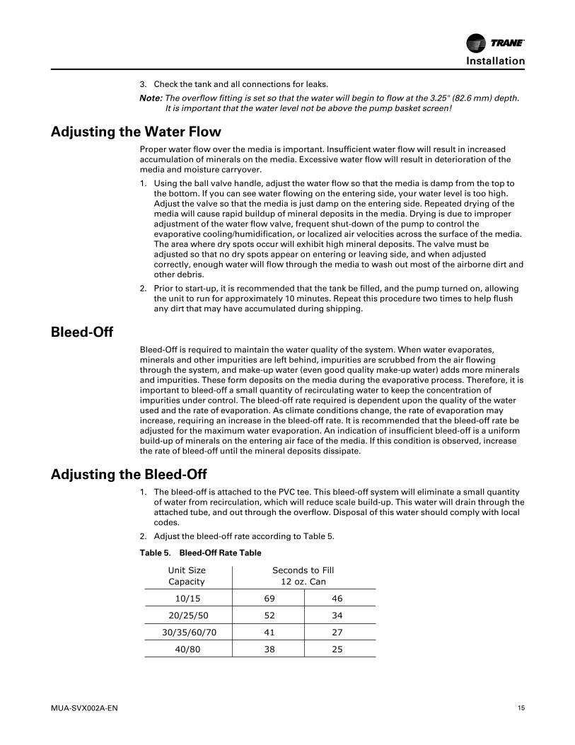
Faucet Use1. To connect the water line to the water supply, install a sillcock and water valve on the faucet.
2. Place tubing nut and ferrule on tube end, and insert valve.
3. Tighten the nuts on the valve and the tube.
NNoottee:: If a faucet is not to be used for the water supply, install the valve on the water line to beused. Follow the procedure above for securing the tubing to the valve.
Figure 8. Evaporative Cooler Water Connections
Adjusting the Water Level and Float ValveFill the tank as follows:
1. Turn the water supply on. Fill the tank to a depth of approximately 3.25" (82.6 mm). Whilefilling the tank, check for good pressure and flow from the float valve.
2. The float valve should shut down the water supply at the 3.25" (82.6 mm) level. It may benecessary to adjust the float valve by bending the rod. The rod level adjustment screw shouldbe set in lower notch on lever.
IInnssttaallllaattiioonn
MUA-SVX002A-EN 15
3. Check the tank and all connections for leaks.
NNoottee:: The overflow fitting is set so that the water will begin to flow at the 3.25" (82.6 mm) depth.It is important that the water level not be above the pump basket screen!
Adjusting the Water FlowProper water flow over the media is important. Insufficient water flow will result in increasedaccumulation of minerals on the media. Excessive water flow will result in deterioration of themedia and moisture carryover.
1. Using the ball valve handle, adjust the water flow so that the media is damp from the top tothe bottom. If you can see water flowing on the entering side, your water level is too high.Adjust the valve so that the media is just damp on the entering side. Repeated drying of themedia will cause rapid buildup of mineral deposits in the media. Drying is due to improperadjustment of the water flow valve, frequent shut-down of the pump to control theevaporative cooling/humidification, or localized air velocities across the surface of the media.The area where dry spots occur will exhibit high mineral deposits. The valve must beadjusted so that no dry spots appear on entering or leaving side, and when adjustedcorrectly, enough water will flow through the media to wash out most of the airborne dirt andother debris.
2. Prior to start-up, it is recommended that the tank be filled, and the pump turned on, allowingthe unit to run for approximately 10 minutes. Repeat this procedure two times to help flushany dirt that may have accumulated during shipping.
Bleed-OffBleed-Off is required to maintain the water quality of the system. When water evaporates,minerals and other impurities are left behind, impurities are scrubbed from the air flowingthrough the system, and make-up water (even good quality make-up water) adds more mineralsand impurities. These form deposits on the media during the evaporative process. Therefore, it isimportant to bleed-off a small quantity of recirculating water to keep the concentration ofimpurities under control. The bleed-off rate required is dependent upon the quality of the waterused and the rate of evaporation. As climate conditions change, the rate of evaporation mayincrease, requiring an increase in the bleed-off rate. It is recommended that the bleed-off rate beadjusted for the maximum water evaporation. An indication of insufficient bleed-off is a uniformbuild-up of minerals on the entering air face of the media. If this condition is observed, increasethe rate of bleed-off until the mineral deposits dissipate.
Adjusting the Bleed-Off1. The bleed-off is attached to the PVC tee. This bleed-off system will eliminate a small quantity
of water from recirculation, which will reduce scale build-up. This water will drain through theattached tube, and out through the overflow. Disposal of this water should comply with localcodes.
2. Adjust the bleed-off rate according to Table 5.
Table 5. Bleed-Off Rate Table
IInnssttaallllaattiioonn
16 MUA-SVX002A-EN
Electrical ConnectionsWWAARRNNIINNGG
HHaazzaarrddoouuss VVoollttaaggee!!FFaaiilluurree ttoo ddiissccoonnnneecctt ppoowweerr bbeeffoorree sseerrvviicciinngg ccoouulldd rreessuulltt iinn ddeeaatthh oorr sseerriioouuss iinnjjuurryy..DDiissccoonnnneecctt aallll eelleeccttrriicc ppoowweerr,, iinncclluuddiinngg rreemmoottee ddiissccoonnnneeccttss bbeeffoorree sseerrvviicciinngg.. FFoolllloowwpprrooppeerr lloocckkoouutt//ttaaggoouutt pprroocceedduurreess ttoo eennssuurree tthhee ppoowweerr ccaann nnoott bbee iinnaaddvveerrtteennttllyyeenneerrggiizzeedd.. VVeerriiffyy tthhaatt nnoo ppoowweerr iiss pprreesseenntt wwiitthh aa vvoollttmmeetteerr..
WWAARRNNIINNGGPPrrooppeerr FFiieelldd WWiirriinngg aanndd GGrroouunnddiinngg RReeqquuiirreedd!!FFaaiilluurree ttoo ffoollllooww ccooddee ccoouulldd rreessuulltt iinn ddeeaatthh oorr sseerriioouuss iinnjjuurryy..AAllll ffiieelldd wwiirriinngg MMUUSSTT bbee ppeerrffoorrmmeedd bbyy qquuaalliiffiieedd ppeerrssoonnnneell.. IImmpprrooppeerrllyy iinnssttaalllleedd aannddggrroouunnddeedd ffiieelldd wwiirriinngg ppoosseess FFIIRREE aanndd EELLEECCTTRROOCCUUTTIIOONN hhaazzaarrddss.. TToo aavvooiidd tthheessee hhaazzaarrddss,,yyoouu MMUUSSTT ffoollllooww rreeqquuiirreemmeennttss ffoorr ffiieelldd wwiirriinngg iinnssttaallllaattiioonn aanndd ggrroouunnddiinngg aass ddeessccrriibbeedd iinnNNEECC aanndd yyoouurr llooccaall//ssttaattee//nnaattiioonnaall eelleeccttrriiccaall ccooddeess..
Refer to the unit data plate to determine the supply voltage.
The motor name-plate and electrical rating on the transformer should be checked beforeenergizing the unit electrical system. All external wiring must conform to ANSI/NFPA No. 70-1996, National Electrical Code (or the latest edition of) and applicable local codes; in Canada, tothe Canadian Electrical Code, Part 1 CSA Standard C22.1
“Dashed” lines represent either field wiring (by others) or optional equipment. Refer to optionalitems (shown on wiring diagram included with unit) - these will be hard wired.
WWAARRNNIINNGGFFiirree HHaazzaarrdd!!FFaaiilluurree ttoo ffoollllooww iinnssttrruuccttiioonnss bbeellooww ccoouulldd ccaauussee aa ffiirree wwhhiicchh ccoouulldd rreessuulltt iinn ddeeaatthh oorrsseerriioouuss iinnjjuurryy,, aanndd pprrooppeerrttyy ddaammaaggee..DDOO NNOOTT jjuummppeerr ffaaccttoorryy wwiirriinngg!! MMiiss--wwiirriinngg ooff ssaaffeettyy cciirrccuuiittss ccoouulldd ccaauussee aa ffiirree.. FFoorr aallllwwiirriinngg ccoonnnneeccttiioonnss,, rreeffeerr ttoo tthhee wwiirriinngg ddiiaaggrraamm sshhiippppeedd wwiitthh tthhee uunniitt.. SShhoouulldd aannyyoorriiggiinnaall wwiirree ssuupppplliieedd wwiitthh tthhee uunniitt hhaavvee ttoo bbee rreeppllaacceedd,, iitt MMUUSSTT bbee rreeppllaacceedd wwiitthh wwiirriinnggmmaatteerriiaall hhaavviinngg aa tteemmppeerraattuurree rraattiinngg ooff aatt lleeaasstt 222211°°FF ((110055°°CC))..
WWAARRNNIINNGGRRiisskk ooff EElleeccttrrooccuuttiioonn!!FFaaiilluurree ttoo ffoollllooww iinnssttrruuccttiioonnss bbeellooww ccoouulldd rreessuulltt iinn ddeeaatthh oorr sseerriioouuss iinnjjuurryy..DDOO NNOOTT uussee aannyy ttoooollss ((ii..ee.. ssccrreewwddrriivveerr,, pplliieerrss,, eettcc..)) aaccrroossss tthhee tteerrmmiinnaallss ttoo cchheecckk ffoorrppoowweerr.. YYoouu MMUUSSTT uussee aa vvoollttmmeetteerr..
NNOOTTIICCEEUUssee CCooppppeerr CCoonndduuccttoorrss OOnnllyy!!FFaaiilluurree ttoo uussee ccooppppeerr ccoonndduuccttoorrss ccoouulldd rreessuulltt iinn eeqquuiippmmeenntt ddaammaaggee aass uunniitt tteerrmmiinnaallss aarreennoott ddeessiiggnneedd ttoo aacccceepptt ootthheerr ttyyppeess ooff ccoonndduuccttoorrss..
IImmppoorrttaanntt:: For all wiring connections, refer to the wiring diagram shipped with the unit (eitheraffixed to the side jacket or enclosed in the unit's installation instruction envelope).Should any original wire supplied with the unit have to be replaced, it must bereplaced with wiring material having a temperature rating of at least 105°C.
It is recommended that the electrical power to each unit be provided by a separate, fused, andpermanently live electrical circuit. A disconnect switch of suitable electrical rating for each unitshould be placed as close to the controls as possible. Each unit must be electrically grounded in
MUA-SVX002A-EN 17
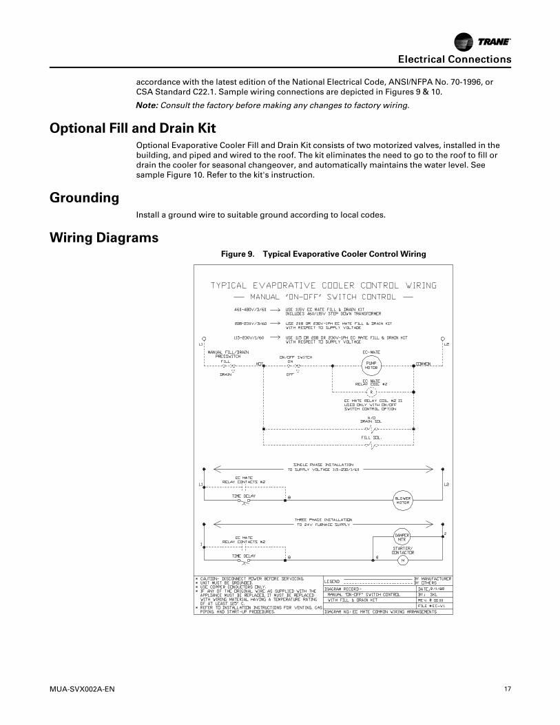
accordance with the latest edition of the National Electrical Code, ANSI/NFPA No. 70-1996, orCSA Standard C22.1. Sample wiring connections are depicted in Figures 9 & 10.
NNoottee:: Consult the factory before making any changes to factory wiring.
Optional Fill and Drain KitOptional Evaporative Cooler Fill and Drain Kit consists of two motorized valves, installed in thebuilding, and piped and wired to the roof. The kit eliminates the need to go to the roof to fill ordrain the cooler for seasonal changeover, and automatically maintains the water level. Seesample Figure 10. Refer to the kit's instruction.
GroundingInstall a ground wire to suitable ground according to local codes.
Wiring DiagramsFigure 9. Typical Evaporative Cooler Control Wiring
EElleeccttrriiccaall CCoonnnneeccttiioonnss

18 MUA-SVX002A-EN
Figure 10. Optional Fill and Drain Kit
EElleeccttrriiccaall CCoonnnneeccttiioonnss
MUA-SVX002A-EN 19
MaintenanceWWAARRNNIINNGG
HHaazzaarrddoouuss VVoollttaaggee!!FFaaiilluurree ttoo ddiissccoonnnneecctt ppoowweerr bbeeffoorree sseerrvviicciinngg ccoouulldd rreessuulltt iinn ddeeaatthh oorr sseerriioouuss iinnjjuurryy..DDiissccoonnnneecctt aallll eelleeccttrriicc ppoowweerr,, iinncclluuddiinngg rreemmoottee ddiissccoonnnneeccttss bbeeffoorree sseerrvviicciinngg.. FFoolllloowwpprrooppeerr lloocckkoouutt//ttaaggoouutt pprroocceedduurreess ttoo eennssuurree tthhee ppoowweerr ccaann nnoott bbee iinnaaddvveerrtteennttllyyeenneerrggiizzeedd.. VVeerriiffyy tthhaatt nnoo ppoowweerr iiss pprreesseenntt wwiitthh aa vvoollttmmeetteerr..
Because of the nature of the evaporative process, algae buildup, biological fouling, scale build-up, and corrosion are distinct possibilities. Proper water treatment and regularly scheduledmaintenance will minimize or eliminate most problems.
1. Cooling Pad Check List:
• Reduce the number of on/off cycles.
• Shade the pads and pump.
• Dry pads out completely once every 24 hours.
• Maintain a suitable water bleed-off rate.
• Drain and disinfect the entire water system quarterly.
• Avoid harmful contaminants, including dust, fumes, harsh cleaners, and water treatmentchemicals.
• Circulate the recommended quantity of water over the pads.
• Avoid dry areas on the pads.
• Clean the filters regularly.
2. Controlling Algae:
• Scale and mineral deposits can form on the cooling pad because the mineral content ofthe water is too high.
• Increase the water flow over the face of the pads.
• Make certain that the flow of water is even from one end of the distribution pipe to theother end.
• Clean and flush the distributor pipe regularly; especially if dry areas appear on the pads.
• Maintain the pH of the recirculating water between 6 and 8.
• Maintain sufficient bleed-off rate.For more details, check MUNTERS® Engineering Bulletin EB-WTM-502.
3. Preventing Algae in the Evaporative Pads:
• Algae needs light, moisture, and nutrients to survive. Eliminating, or reducing, theseelements will help to control algae. For specific details, see MUNTERS® EngineeringBulletin EB-WTM-502.
4. Biological Fouling Control:
• Uncontrolled growth of organic matter can lead to plugged media, metal deterioration,and biological contamination of the airstream. Whenever the possibility of biologicalcontamination of water in an airstream exists, transmittal of Legionnaire’s Disease shouldbe addressed. While there are no reported cases of Legionnaire’s Disease associated withrigid media type evaporative cooling systems, the Legionella Pneumophila bacteria ispresent in almost all water supplies. However, the mere presence of the bacteria does notcreate a hazard: the bacteria must be transmitted as an aerosol in sufficient densities to beinfectious.
NNoottee:: It is highly recommended that the services of a water treatment company be retained toadvise on the proper treatment of the sump water for biological, scale, and corrosioncontrol. For more information, see MUNTERS® Engineering Bulletin EB-WTM-502.
20 MUA-SVX002A-EN
Maintenance ScheduleRegular maintenance is the key to successful service from your Evaporative Cooler. Use thefollowing schedule as a guide to maintain your unit:
Table 6. Maintenance Schedule
Maintenance Requirements Annual Start-Up Annual Shutdown
Changing Media At beginning of 6th year or ifpassages are blocked
Water Pump Cleaning X
Cleaning & Touch-Up X
Adjusting Bleed-Off X
Periodic Inspection During cooling season During cooling season
Washing Down Media with Hose As required during season
Inlet Filter Washing with Hose X X
Drain Unit X
NNoottee:: The procedures in the Maintenance Schedule are explained in the following sections.
Changing the MediaThis should be done every 5 years or if passages become blocked.
1. Remove filter/frame assemblies.
2. Disconnect the water hood panel from the top panel by removing screws.
3. Snap out water distribution system.
4. Remove top media distribution pad.
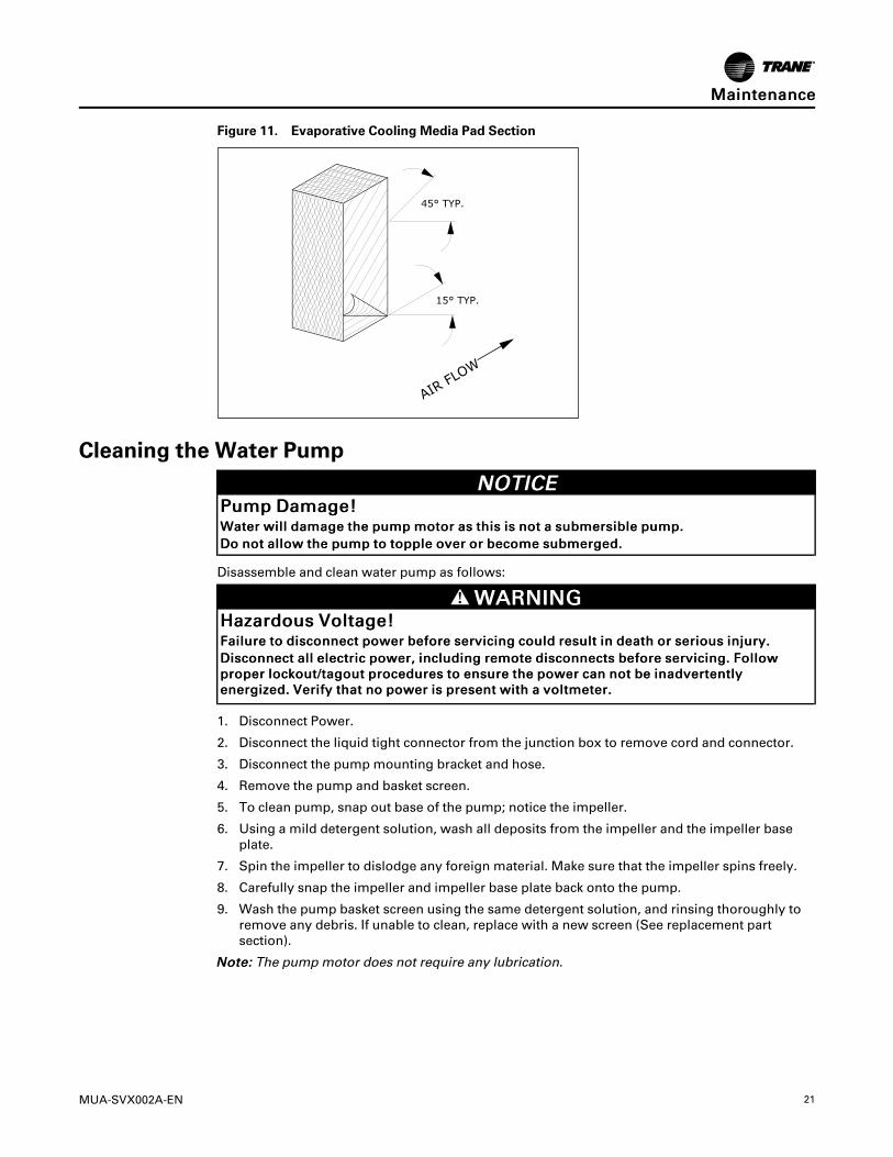
5. Lift out media sections (Note the position of media with respect to airflow. See Figure 11, p.20
6. Replace with new CELdek® media sections. (See “Evaporative Cooler Parts andIdentification,” p. 12). Aspen and other evaporative media will not work.
7. When re-installing media, be sure all media sections are installed in the proper direction. SeeFigure 11, p. 20
8. Replace top media distribution pad, water distribution system, water hood panel, and filter/frame assemblies.
MMaaiinntteennaannccee
MUA-SVX002A-EN 21
Figure 11. Evaporative Cooling Media Pad Section
Cleaning the Water PumpNNOOTTIICCEE
PPuummpp DDaammaaggee!!WWaatteerr wwiillll ddaammaaggee tthhee ppuummpp mmoottoorr aass tthhiiss iiss nnoott aa ssuubbmmeerrssiibbllee ppuummpp..DDoo nnoott aallllooww tthhee ppuummpp ttoo ttooppppllee oovveerr oorr bbeeccoommee ssuubbmmeerrggeedd..
Disassemble and clean water pump as follows:
WWAARRNNIINNGGHHaazzaarrddoouuss VVoollttaaggee!!FFaaiilluurree ttoo ddiissccoonnnneecctt ppoowweerr bbeeffoorree sseerrvviicciinngg ccoouulldd rreessuulltt iinn ddeeaatthh oorr sseerriioouuss iinnjjuurryy..DDiissccoonnnneecctt aallll eelleeccttrriicc ppoowweerr,, iinncclluuddiinngg rreemmoottee ddiissccoonnnneeccttss bbeeffoorree sseerrvviicciinngg.. FFoolllloowwpprrooppeerr lloocckkoouutt//ttaaggoouutt pprroocceedduurreess ttoo eennssuurree tthhee ppoowweerr ccaann nnoott bbee iinnaaddvveerrtteennttllyyeenneerrggiizzeedd.. VVeerriiffyy tthhaatt nnoo ppoowweerr iiss pprreesseenntt wwiitthh aa vvoollttmmeetteerr..
1. Disconnect Power.
2. Disconnect the liquid tight connector from the junction box to remove cord and connector.
3. Disconnect the pump mounting bracket and hose.
4. Remove the pump and basket screen.
5. To clean pump, snap out base of the pump; notice the impeller.
6. Using a mild detergent solution, wash all deposits from the impeller and the impeller baseplate.
7. Spin the impeller to dislodge any foreign material. Make sure that the impeller spins freely.
8. Carefully snap the impeller and impeller base plate back onto the pump.
9. Wash the pump basket screen using the same detergent solution, and rinsing thoroughly toremove any debris. If unable to clean, replace with a new screen (See replacement partsection).
NNoottee:: The pump motor does not require any lubrication.
MMaaiinntteennaannccee
22 MUA-SVX002A-EN
Washing the MediaNNOOTTIICCEE
BBlloowweerr MMoottoorr DDaammaaggee!!DDoo nnoott ssppllaasshh wwaatteerr oonn tthhee bblloowweerr mmoottoorr aass iitt ccoouulldd rreessuulltt iinn eelleeccttrriiccaall sshhoorrttss aanndd bblloowweerrmmoottoorr ddaammaaggee..
1. Scale and dust should be washed off the intake side of the media annually, using a gardenhose and nozzle; this will help to unclog passages.
2. Using a stiff brush, lightly brush the intake edges of the media. This will not harm theopenings, but will remove any hardened scale.
3. Occasionally, there will be a build-up of algae or odors. The best solution for both of theseproblems is to allow the pads to dry thoroughly on a regular basis. If cooling is not needed atnight during the cooling season, allow the blower to run for a few hours after the pump hasbeen shut-down to dry pads daily.
4. During the cooling season, we recommend that the pads be shut down nightly if possiblewith the blower running to dry the pads out for a few hours before the unit is shut down.
Washing the Inlet FilterThe pre-filter should be cleaned periodically as follows:
1. Turn the four latches and remove filter frame assemblies.
2. Carefully remove the aluminum filters. Wash the filters with warm water and a mild soap,rinse thoroughly.
3. Re-install in unit.
4. If the aluminum mesh filters are damaged or cannot be cleaned, replace the mesh filter (Seereplacement parts section).
Cabinet Cleaning and Touch-UpThe cabinet and all internal parts of the Evaporative Cooler should be cleaned annually using asoft cloth, warm water, and a mild cleanser.
NNoottee:: Avoid using steel wool or sandpaper in normal cleaning of the unit.
Winter Shut Down1. Clean and flush out Evaporative Cooler media and sump.
2. Clean water distributor holes.
3. Drain fill pipe and leave open. DO NOT LEAVE ANY WATER IN THE SYSTEM. FREEZING CANCAUSE MAJOR DAMAGE TO THE UNIT.
4. Remove and clean pump if necessary.
5. Check sump tank for leaks and repair if necessary. Sump tank is fabricated from stainlesssteel.
MMaaiinntteennaannccee

MUA-SVX002A-EN 23
Roof Curb Kit — Part Number 0134-0212-01*
For use with:Evaporative Cooler ModuleCapacities — 10/40*Evaporative Cooler Platform Only
NNoottee:: *One Platform Kit fits All Evaporative Cooler Modules/Capacities (CA) - 10/80
Ingersoll Rand (NYSE: IR) advances the quality of life by creating comfortable, sustainable and efficientenvironments. Our people and our family of brands — including Club Car®, Ingersoll Rand®, Thermo King® andTrane® —work together to enhance the quality and comfort of air in homes and buildings; transport and protectfood and perishables; and increase industrial productivity and efficiency. We are a global business committed to aworld of sustainable progress and enduring results.
ingersollrand.com
Ingersoll Rand has a policy of continuous product and product data improvements and reserves the right to change design and specificationswithout notice.We are committed to using environmentally conscious print practices.
MUA-SVX002A — EN 01 Mar 2017
Supersedes (New) ©2017 Ingersoll Rand | all rights reserved