metal enclosures and cabinets - training -...
TRANSCRIPT

METAL ENCLOSURES AND CABINETS
2014CATALOGUE
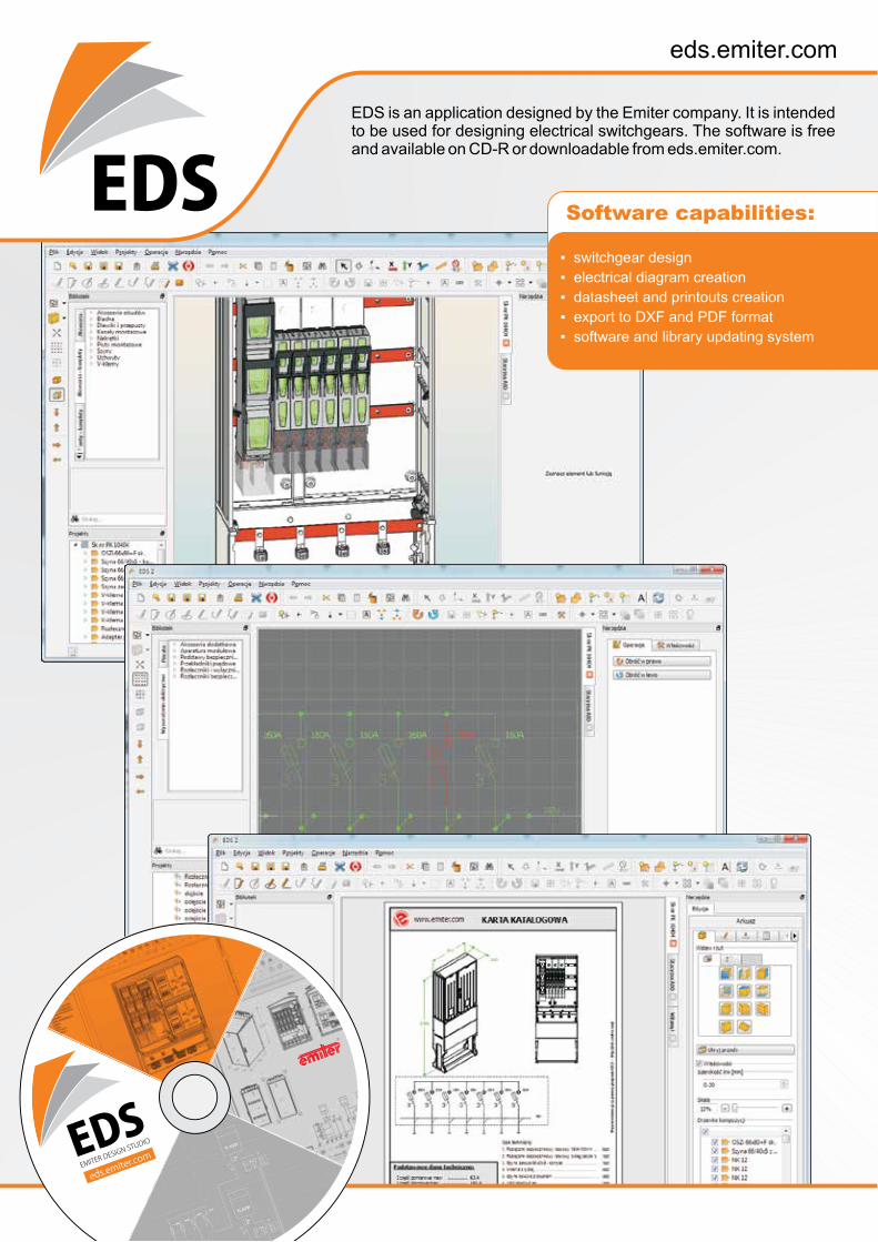
EDS is an application designed by the Emiter company. It is intendedto be used for designing electrical switchgears. The software is freeand available on CD-R or downloadable from eds.emiter.com.
▪ switchgear design
▪ electrical diagram creation
▪ datasheet and printouts creation
▪ export to DXF and PDF format
▪ software and library updating system
Software capabilities:

pages 157-166
pages 131-155
pages 11-129
Technical information
Universal equipment
Metal enclosuresand cabinets
EDS is an application designed by the Emiter company. It is intendedto be used for designing electrical switchgears. The software is freeand available on CD-R or downloadable from eds.emiter.com.
▪ switchgear design
▪ electrical diagram creation
▪ datasheet and printouts creation
▪ export to DXF and PDF format
▪ software and library updating system
Software capabilities:

enclosure type picture indoor - I
outdoor - O material IP degreerange of
dimensionsmin / max
recommended application
mounting place
page number
DEDEK O A IP31 250×250 /
400×500
•newcoverofflushmountedswitch-gears
•wall 12-13
OMUOMK I S IP31 200×300×150 /
1000×1200×300•universal•general purpose
•wall•flush
mounted14-19
OMSI S
IP65IP55
200×300×150 /1000×1400×400
•universal•general purpose
•wall•hardened
surface•buried
20-27O AZ, A, SS
SU O AZ, A, SS IP43 280×880×335 /1200×2000×500
•universal•general purpose
•hardenedsurface
•buried28-33
DSU(DIN
standard)O AZ, A, SS IP43 460×890×320 /
1120×1200×340
•universal•general purpose•DIN - standard
dimensions
•hardenedsurface
•buried34-35
SUW O AZ IP43 500×900×320 /1150×1200×340
•universal•general purpose•reinforced•harbours•railways•mines
•hardenedsurface
•buried42-43
SR I S IP30IP55
400×1600×400 /1200×2000×600
•universal•control•IT•cable TV•switchgears•electricity distribu-
tion and measure- ment
•floor 44-68
SN O AZ IP43 535×880×335 /1000×880×335
•universal•control•IT•cable TV•switchgears•electricity distribu-
tion and measure- ment
•wall 69-70
OWW I S IP43 400×1600×400 /1200×2000×600
•universal•general purpose•control•switchgears•electricity distribu-
tion and measure- ment
•floor 71-76
SSU I S IP43 600×1600×400 /1200×2000×500 •universal •floor 77-79
METAL ENCLOSURES•Main features of metal cabinets and their recommended applications

enclosure type picture indoor - I
outdoor - O material IP degreerange of
dimensionsmin / max
recommended application
mounting place
page number
SSS
I S
IP55 400×1600×400 /1200×2000×600
•universal•general purpose•control•switchgears,•electricity distribu-
tion and measure- ment
•floor 80-86
O AZ, A, SS
PSAPSB I S IP55 600×970×450 /
1500×1350×800 •control •floor 87-90
SKSKP
SKPOO A IP44 400×950×320 /
1250×1750×400
•switchgears•electricity distribu-
tion and measu-rement
• lighting
•hardenedsurface
•buried91-95
SWAPSWAPO O A IP44 1300×850×500 /
1500×1150×500
•switchgears•electricity distribu-
tion and measure- ment
• lighting
• in wall mounted 96-97
ORM I S IP43 350×2000×300 /1150×2000×300
•electricity distribu-tion and measure- ment
•TV•phone
•floor 98-101
ORMUORMK I S IP30 560×600×200 /
560×1050×200
•electric circuit protection using modular devices
•wall•flush
mounted102-103
ORP I S IP30 264×1594×250 /660×1800×250
•electricity distribu-tion and measu-rement
•circuit protection
•floor 104-107
ORW I S IP30 600×1800×250 /1200×2000×400
•electricity distribu-tion and measure- ment
•circuit protection
•floor 108-111
Designation:A- aluminium AlMg3S - carbon steel DC01AZ - aluzinc plated steel AZ 150SS - stainless steel V2A, AISI 304

RSO O AZ IP44 1010×1020×760 /1280×1500×860
•switchgears•electricity distri-
bution•measurement and
protection
•pole 120-122
NTw O AZ IP20 depends onconfiguration
•switchgears•electricity distri-
bution•measurement and
protection
•trans-former station
123-127
ORB O AZ IP43 550×600×300 /550×800×300
•electricity distri-bution
•measurement and protection
•construc-tion site 128-129
enclosure type picture indoor - I
outdoor - O material IP degreerange of
dimensionsmin / max
recommended application
mounting place
page number
ST/A O A IP44 600×1280×600 /1200×1333×600
•switchgears•electricity distri-
bution•measurement and
protection
•pole 112-119
Designation:A- aluminium AlMg3AZ - aluzinc plated steel AZ 150
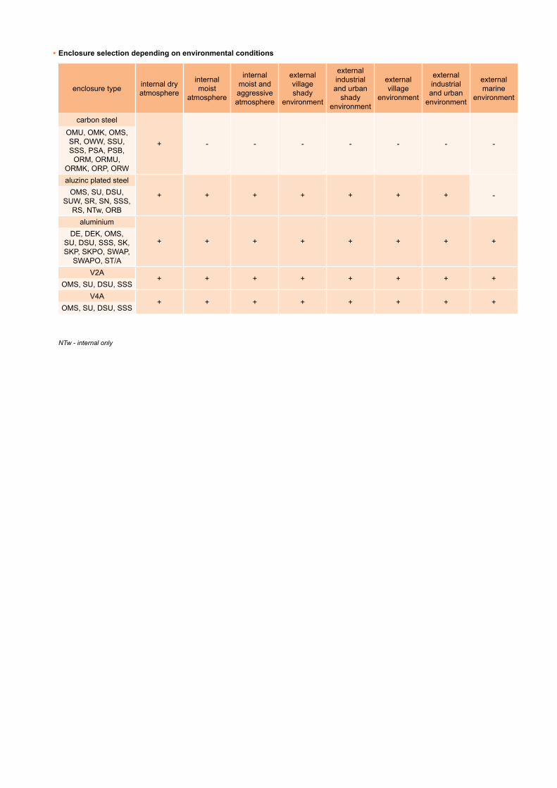
•Enclosure selection depending on environmental conditions
enclosure type internal dry atmosphere
internal moist
atmosphere
internal moist and aggressive atmosphere
external village shady
environment
external industrial and urban shady
environment
external village
environment
external industrial and urban
environment
external marine
environment
carbon steel
+ - - - - - - -OMU, OMK, OMS, SR, OWW, SSU, SSS, PSA, PSB,
ORM, ORMU, ORMK, ORP, ORWaluzinc plated steel
+ + + + + + + -OMS, SU, DSU, SUW, SR, SN, SSS,
RS, NTw, ORBaluminium
+ + + + + + + +DE, DEK, OMS,
SU, DSU, SSS, SK, SKP, SKPO, SWAP,
SWAPO, ST/AV2A
+ + + + + + + +OMS, SU, DSU, SSS
V4A+ + + + + + + +
OMS, SU, DSU, SSS
NTw - internal only

Contents
Metal enclosures and cabinetsFacade doors (DE, DEk) _______________________________________________________________________________________ 12Universal wall mounted enclosures (OMU) _________________________________________________________________________ 14
Accessories for OMU enclosures _______________________________________________________________________________ 16Universalflushmountedenclosure,withcollar(OMK) ________________________________________________________________ 17Universaltightenclosures(OMS) ________________________________________________________________________________ 20
Standard equipment for OMS enclosures _________________________________________________________________________ 22OMS enclosures accessories __________________________________________________________________________________ 23
Free-standing cabinets (SU, SUJ) ________________________________________________________________________________ 28Free-standing DIN style cabinets (DSU) ___________________________________________________________________________ 34Foundations and socles for cabinets type SU, SUJ, DSU (FN, FZ, CW, CZ, FB) ____________________________________________ 36Free-standing reinforced cabinets (SUW) __________________________________________________________________________ 42Frame cabinets (SR) __________________________________________________________________________________________ 44
Accessories for SR cabinets ___________________________________________________________________________________ 47Accessories for SR cabinet - bracket system ______________________________________________________________________ 62
Facade cabinets (SN) _________________________________________________________________________________________ 69Free-standing indoor cabinets (OWW) ____________________________________________________________________________ 71
Accessories for OWW cabinets _________________________________________________________________________________ 74Universal control cabinets (SSU) _________________________________________________________________________________ 77Tightcontrolcabinets(SSS) ____________________________________________________________________________________ 80
Accessories for SSS cabinets __________________________________________________________________________________ 83Control desks (PSA) __________________________________________________________________________________________ 87Control desks (PSB) __________________________________________________________________________________________ 89Switchgearcabinetswithmeasuringandarealightingcompartments(SK,SKP,SKPO) ______________________________________ 91Towerswitchgearcabinets(SWAP,SWAPO) _______________________________________________________________________ 96Enclosuresformodularswitchgears(ORM) ________________________________________________________________________ 98Universalenclosuresformodularswitchgear:wallmounted(ORMU),flushmounted(ORMK) ________________________________ 102Floorswitchgearenclosures(ORP) ______________________________________________________________________________ 104Enclosuresforfree-standingswitchgear(ORW) ____________________________________________________________________ 108Configurationofbaseequipment ______________________________________________________________________________ 110
Enclosureforpoletransformerstationswitchgear(ST/A) _____________________________________________________________ 112Accessories _______________________________________________________________________________________________ 113
Enclosureforpoletransformerstationswitchgear(RSO) _____________________________________________________________ 120Accessories _______________________________________________________________________________________________ 122
Enclosureforinternaltransformerstationswitchgear(NTw) ___________________________________________________________ 123Enclosureforconstructionsiteswitchgears(ORB) __________________________________________________________________ 128
universal equipMentBusbar masking panels (OZB, OZC) _____________________________________________________________________________ 132Distance pins (KL) ___________________________________________________________________________________________ 132Cage nuts (NKK) ____________________________________________________________________________________________ 133Sightglasses(W,WE,WS) ____________________________________________________________________________________ 133LacquerfortherenovationofmetalcabinetsstandardcolourRAL7035(LRS) ____________________________________________ 133Locks (RS, RW, ED, CZ, M, PM, Z) ______________________________________________________________________________ 134Lock inserts (WRS, WRH) _____________________________________________________________________________________ 134Counter plates (T, TLE) _______________________________________________________________________________________ 134Insulators (D, HH) ___________________________________________________________________________________________ 135Pocket for documents (KD) ____________________________________________________________________________________ 135Mounting plates (PMPN, PMV) _________________________________________________________________________________ 136Lifting rings (NZU) ___________________________________________________________________________________________ 137Gripsforattachingcabinetstopoles(UN,UPN,KUN,KUPN) _________________________________________________________ 138Enclosureholder(UMO) ______________________________________________________________________________________ 139Glands (RL) ________________________________________________________________________________________________ 139Busbar support (WT) _________________________________________________________________________________________ 140Busbar support (WTBW) ______________________________________________________________________________________ 146Powerbusbarsupport-horizontal(WTBW45×410M12) _____________________________________________________________ 149Ventilation plugs (SLU) _______________________________________________________________________________________ 153Cableholders(PUK,PUK3,KO4) _______________________________________________________________________________ 153Cabinetlighting(MERA) ______________________________________________________________________________________ 155
technical inforMationProperties and application of paint coatings performed in EMITER _____________________________________________________ 158Type of environments ________________________________________________________________________________________ 158Clasificationofatmosphericcorrosiveenvironmentstemperateclimateacc.toPN-ENISO12500:2000 ________________________ 158Typesoftreatmentsandcoatings,dependingontheoperatingconditionsforthedurabilityofthecoating10yearstofirstmaintenance.NotusedinEmiter. __________________________________________________________________________________________ 159Saltmisttestdurationversuscorrosioncategorytypeforthedurabilityofthecoating10yearstofirstmaintenance _______________ 159Lossofzincandaluzinclayerthicknessdependingonenvironmentconditions ____________________________________________ 160Thicknessofthezincandaluzinclayer ___________________________________________________________________________ 160Durabilityofthecoating _______________________________________________________________________________________ 160Materials versus electrolytic corrosion avoidance ___________________________________________________________________ 160Tighteningmomentsforboltsusedinelectricalconnections___________________________________________________________ 161Current carrying capacity of copper busbars _______________________________________________________________________ 161Current carrying capacity of aluminium busbars ____________________________________________________________________ 162Current carrying capacity of wires and cables ______________________________________________________________________ 163Minimum and maximum Cu cables cross sections, versus current ______________________________________________________ 163Heatingpoweroftheheaterintheenclosure ______________________________________________________________________ 164Dissipated power ____________________________________________________________________________________________ 164Degree of protection, IP codes _________________________________________________________________________________ 164Impact protection, IK codes ____________________________________________________________________________________ 165MetalenclosureswithprotectionclassIIB _________________________________________________________________________ 165RAL scale colour table ________________________________________________________________________________________ 166

Metal enclosures and cabinets
obu-start

The
prod
ucer
rese
rves
the
right
to in
trodu
ce te
chni
cal m
odifi
catio
ns
www.emiter.com
Met
al e
nclo
sure
s &
cab
inet
s
12
Facade doorsDE • DEk
Application
•To be mounted into facade cavity after polystyrene foam insulation, instead of old doors of electricenclosure.
Type of installation
•DoorstobeplacedinthecavityofthenewfacadeandfixedbyfourexpansionboltsdiaØ8tothewall.
Design
•Thedoorandframearemadeofaluminiumsheet;•Polyesterstructuralpowderpainted,colourRAL7035;•ThedoorsareclosedbythecylinderlockZ2106typeinDEversionandadditionallybypadlockinDEkversion;
•Itispossibletoinstallthedoorontherightorleftsideoftheframe.
Technical data
•Protectionclass:I;•Ingressprotectiondegree:IP31;•Impactprotectiondegree:IK10.
Dimensions
A
C
BD
18
26
Reference chart
type dimension A [mm]
dimension B [mm]
dimension C [mm]
dimension D [mm]
Mounting dimensionsof facade cavity [mm]
DE 25 25DEk 25 25 250 250 306 304 260×260
DE 30 30DEk 30 30 300 300 356 354 310×310
DE 30 40DEk 30 40 300 400 356 454 310×410
DE 40 40DEk 40 40 400 400 456 454 410×410
DE 50 40DEk 50 40 500 400 556 454 510×410
DE 45 52DEk 45 52 450 520 506 574 460×530
DE 54 37DEk 54 37 540 370 596 424 550×380
DE 39 49DEk 39 49 390 490 446 444 400×500
DE 40 50DEk 40 50 400 500 456 554 410×510
DE 34 49DEk 34 39 340 390 396 444 350×400
Facade doors (DE, DEk) DEk_start

The
prod
ucer
rese
rves
the
right
to in
trodu
ce te
chni
cal m
odifi
catio
ns
Met
al e
nclo
sure
s &
cab
inet
s
13
DE • DEk
How to order
DE
Facade door
Way of closing
without mark - cylinder lockk - additional lugs for padlock
External dimension number [cm]
width (C)
height (D)
-
Additional requirements description
•Orderingexample: - FacadedoorDE3949.
Scope of delivery
•Facadedoor;•Keyforthelock(number1333).
DEk_end

The
prod
ucer
rese
rves
the
right
to in
trodu
ce te
chni
cal m
odifi
catio
ns
www.emiter.com
Met
al e
nclo
sure
s &
cab
inet
s
14
Universal wall mounted enclosuresOMU
Application
•Indoorenclosuresforswitchgears,controldevicesforprocessesandmachines.
Type of installation
•Indoor;•Wallmounted.
Operating conditions
•Indoor;•Dryenvironment.
Design
•Carbonsteel,thickness1-1,5mm;•Polyesterstructuralpowderpainted,colourRAL7035;•Concealeddoorwithoutgasket,right-leftsidehangingpossible;•Mountingholesonthebackwall;•Mountingplatemadeofaluzincplatedsteel,thickness1-2mm;•Earthingscrews;•Doorclosing:cylinderlockZ-2106;•Doorcanbeequippedwithpolycarbonatewindow(fromdimensions×w=400×400mm).
Technical data
•Protectionclass:I;•Ingressprotectiondegree:IP31;•Impactprotection:
- IK10 - for standard door, - IK07-forwindowdoor.
Dimensions
w
s
A
A
back view
410
×Ø
s-72
w-7
2
s-52
w-5
2
clearance
g-31,5
g
mounting plateA-A
w-1
20
s-120100
option
Universal wall mounted enclosures (OMU) OMU_start
The
prod
ucer
rese
rves
the
right
to in
trodu
ce te
chni
cal m
odifi
catio
ns
Met
al e
nclo
sure
s &
cab
inet
s
15
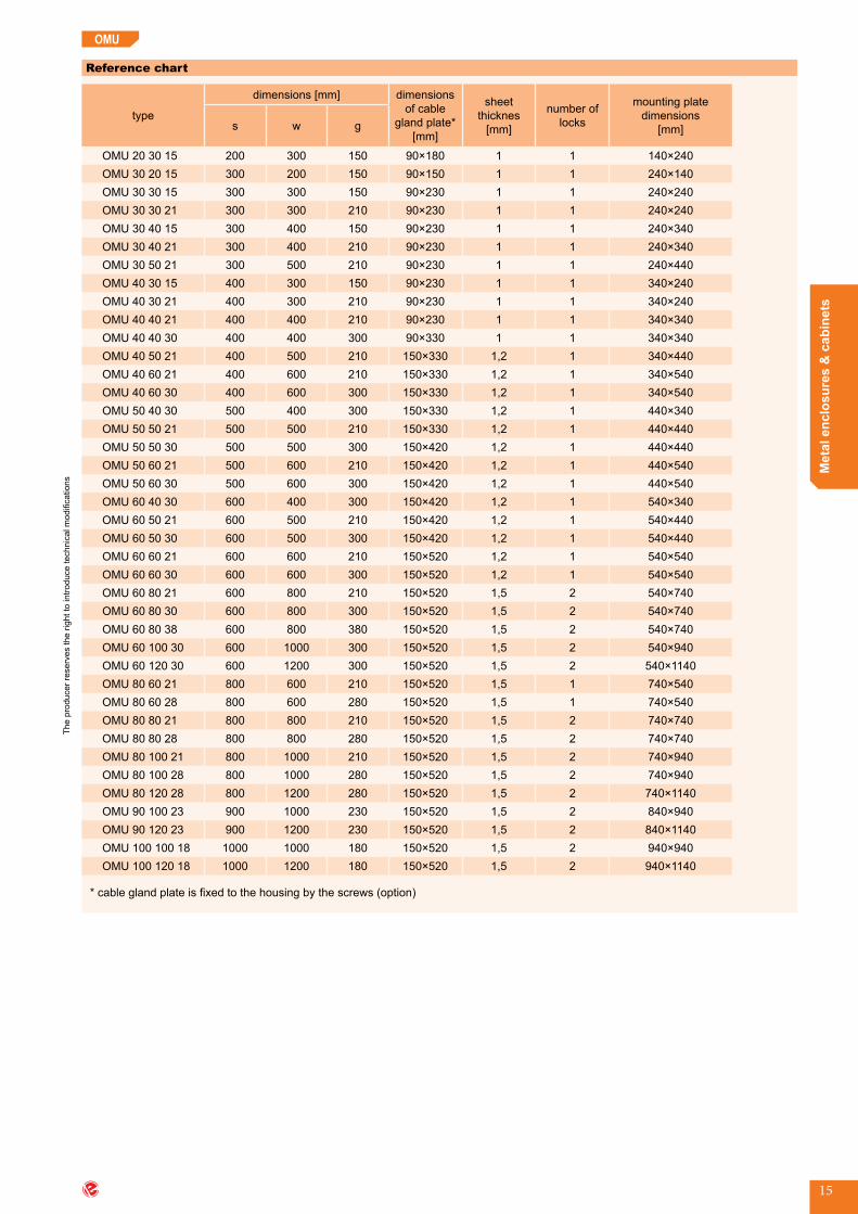
OMU
Reference chart
type
dimensions [mm] dimensions of cable
gland plate* [mm]
sheetthicknes
[mm]
number of locks
mounting plate dimensions
[mm]s w g
OMU 20 30 15 200 300 150 90×180 1 1 140×240OMU 30 20 15 300 200 150 90×150 1 1 240×140OMU 30 30 15 300 300 150 90×230 1 1 240×240OMU 30 30 21 300 300 210 90×230 1 1 240×240OMU 30 40 15 300 400 150 90×230 1 1 240×340OMU 30 40 21 300 400 210 90×230 1 1 240×340OMU 30 50 21 300 500 210 90×230 1 1 240×440OMU 40 30 15 400 300 150 90×230 1 1 340×240OMU 40 30 21 400 300 210 90×230 1 1 340×240OMU 40 40 21 400 400 210 90×230 1 1 340×340OMU 40 40 30 400 400 300 90×330 1 1 340×340OMU 40 50 21 400 500 210 150×330 1,2 1 340×440OMU 40 60 21 400 600 210 150×330 1,2 1 340×540OMU 40 60 30 400 600 300 150×330 1,2 1 340×540OMU 50 40 30 500 400 300 150×330 1,2 1 440×340OMU 50 50 21 500 500 210 150×330 1,2 1 440×440OMU 50 50 30 500 500 300 150×420 1,2 1 440×440OMU 50 60 21 500 600 210 150×420 1,2 1 440×540OMU 50 60 30 500 600 300 150×420 1,2 1 440×540OMU 60 40 30 600 400 300 150×420 1,2 1 540×340OMU 60 50 21 600 500 210 150×420 1,2 1 540×440OMU 60 50 30 600 500 300 150×420 1,2 1 540×440OMU 60 60 21 600 600 210 150×520 1,2 1 540×540OMU 60 60 30 600 600 300 150×520 1,2 1 540×540OMU 60 80 21 600 800 210 150×520 1,5 2 540×740OMU 60 80 30 600 800 300 150×520 1,5 2 540×740OMU 60 80 38 600 800 380 150×520 1,5 2 540×740OMU 60 100 30 600 1000 300 150×520 1,5 2 540×940OMU 60 120 30 600 1200 300 150×520 1,5 2 540×1140OMU 80 60 21 800 600 210 150×520 1,5 1 740×540OMU 80 60 28 800 600 280 150×520 1,5 1 740×540OMU 80 80 21 800 800 210 150×520 1,5 2 740×740OMU 80 80 28 800 800 280 150×520 1,5 2 740×740OMU 80 100 21 800 1000 210 150×520 1,5 2 740×940OMU 80 100 28 800 1000 280 150×520 1,5 2 740×940OMU 80 120 28 800 1200 280 150×520 1,5 2 740×1140OMU 90 100 23 900 1000 230 150×520 1,5 2 840×940OMU 90 120 23 900 1200 230 150×520 1,5 2 840×1140OMU 100 100 18 1000 1000 180 150×520 1,5 2 940×940OMU 100 120 18 1000 1200 180 150×520 1,5 2 940×1140
*cableglandplateisfixedtothehousingbythescrews(option)

The
prod
ucer
rese
rves
the
right
to in
trodu
ce te
chni
cal m
odifi
catio
ns
www.emiter.com
Met
al e
nclo
sure
s &
cab
inet
s
16
OMU
How to order
OMU
Universal enclosure
width (s)
height (w)
External dimension number [cm]
depth (g)
Material of enclosure
without mark - carbon steel
other material - on request
Additional requirements description
-
•Orderingexample: - UniversalenclosurewithmountingplateOMU304050.
Mounting plate for OMU enclosures
w-1
25
w-6
0
s-80
s-60
410
×Ø
8
•Material:aluzincplatedsteel,thicknes1-2mm.
ACCESSORIES FOR OMU ENCLOSURES
Application
•FixingOMUenclosuretothewall.
Design
•Wallholderkitconsistsof: - holder(MZ1719), - M8x10 screw, - nut(M1971).
How to order
•MZ2259wallholderkit.
Wall holder
Accessories for OMU enclosures

The
prod
ucer
rese
rves
the
right
to in
trodu
ce te
chni
cal m
odifi
catio
ns
Met
al e
nclo
sure
s &
cab
inet
s
17
Universal flush mounted enclosure, with collarOMK
Application
•Enclosuresforswitchgears,controldevicesforprocessesandmachines.
Type of installation
•Indoor;•Flushmounted.
Operating conditions
•Indoor;•Dryenvironment.
Design
•Carbonsteel1-1,5mm;•Polyesterstructuralpowderpainted,colourRAL7035;•Concealeddoorwithoutgasket,right-leftsidehangingpossible;•Mountingplatemadeofaluzincplatedsteel,thickness1-2mm;•Earthingscrews;•Doorclosing:cylinderlockZ-2106;•Doorcanbeequippedwithpolycarbonatewindow(fromdimensions×w=400×400mm).
Technical data
•Protectionclass:I;•Ingressprotectiondegree:IP31;•Impactprotection:
- IK10 - for standard door, - IK07-forwindowdoor.
Dimensions
A
A
mounting plateA-A
s+50
s
g-31,5
g
w+
50
w
w-5
2
s-52
clearance
w-1
20
s-120100
option
Universal flush mounted enclosure, with collar (OMK)
The
prod
ucer
rese
rves
the
right
to in
trodu
ce te
chni
cal m
odifi
catio
ns
www.emiter.com
Met
al e
nclo
sure
s &
cab
inet
s
18
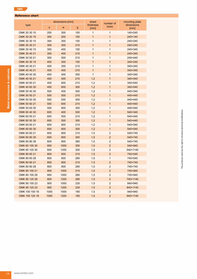
Reference chart
typedimensions [mm] sheet
thickness[mm]
number of locks
mounting plate dimensions
[mm]s w g
OMK 20 30 15 200 300 150 1 1 140×240OMK 30 20 15 300 200 150 1 1 240×140OMK 30 30 15 300 300 150 1 1 240×240OMK 30 30 21 300 300 210 1 1 240×240OMK 30 40 15 300 400 150 1 1 240×340OMK 30 40 21 300 400 210 1 1 240×340OMK 30 50 21 300 500 210 1 1 240×440OMK 40 30 15 400 300 150 1 1 340×240OMK 40 30 21 400 300 210 1 1 340×240OMK 40 40 21 400 400 210 1 1 340×340OMK 40 40 30 400 400 300 1 1 340×340OMK 40 50 21 400 500 210 1,2 1 340×440OMK 40 60 21 400 600 210 1,2 1 340×540OMK 40 60 30 400 600 300 1,2 1 340×540OMK 50 40 30 500 400 300 1,2 1 440×340OMK 50 50 21 500 500 210 1,2 1 440×440OMK 50 50 30 500 500 300 1,2 1 440×440OMK 50 60 21 500 600 210 1,2 1 440×540OMK 50 60 30 500 600 300 1,2 1 440×540OMK 60 40 30 600 400 300 1,2 1 540×340OMK 60 50 21 600 500 210 1,2 1 540×440OMK 60 50 30 600 500 300 1,2 1 540×440OMK 60 60 21 600 600 210 1,2 1 540×540OMK 60 60 30 600 600 300 1,2 1 540×540OMK 60 80 21 600 800 210 1,5 2 540×740OMK 60 80 30 600 800 300 1,5 2 540×740OMK 60 80 38 600 800 380 1,5 2 540×740OMK 60 100 30 600 1000 300 1,5 2 540×940OMK 60 120 30 600 1200 300 1,5 2 540×1140OMK 80 60 21 800 600 210 1,5 2 740×540OMK 80 60 28 800 600 280 1,5 1 740×540OMK 80 80 21 800 800 210 1,5 2 740×740OMK 80 80 28 800 800 280 1,5 2 740×740OMK 80 100 21 800 1000 210 1,5 2 740×940OMK 80 100 28 800 1000 280 1,5 2 740×940OMK 80 120 28 800 1200 280 1,5 2 740×1140OMK 90 100 23 900 1000 230 1,5 2 840×940OMK 90 120 23 900 1200 230 1,5 2 840×1140OMK 100 100 18 1000 1000 180 1,5 2 940×940OMK 100 120 18 1000 1200 180 1,5 2 940×1140
OMK
The
prod
ucer
rese
rves
the
right
to in
trodu
ce te
chni
cal m
odifi
catio
ns
Met
al e
nclo
sure
s &
cab
inet
s
19
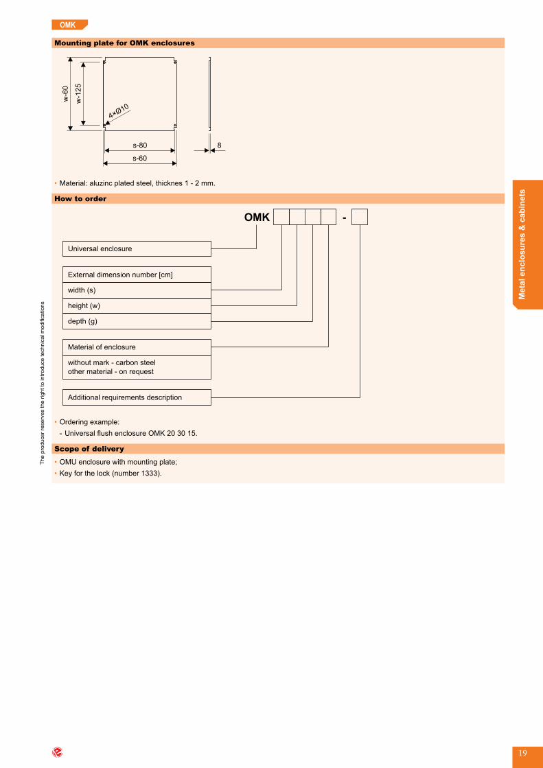
Mounting plate for OMK enclosures
w-1
25
w-6
0
s-80
s-60
410
×Ø
8
•Material:aluzincplatedsteel,thicknes1-2mm.
Scope of delivery
•OMUenclosurewithmountingplate;•Keyforthelock(number1333).
How to order
OMK
Universal enclosure
width (s)
height (w)
External dimension number [cm]
depth (g)
Material of enclosure
without mark - carbon steel
other material - on request
Additional requirements description
-
•Orderingexample: - UniversalflushenclosureOMK203015.
OMK
OMU_end
The
prod
ucer
rese
rves
the
right
to in
trodu
ce te
chni
cal m
odifi
catio
ns
www.emiter.com
Met
al e
nclo
sure
s &
cab
inet
s
20
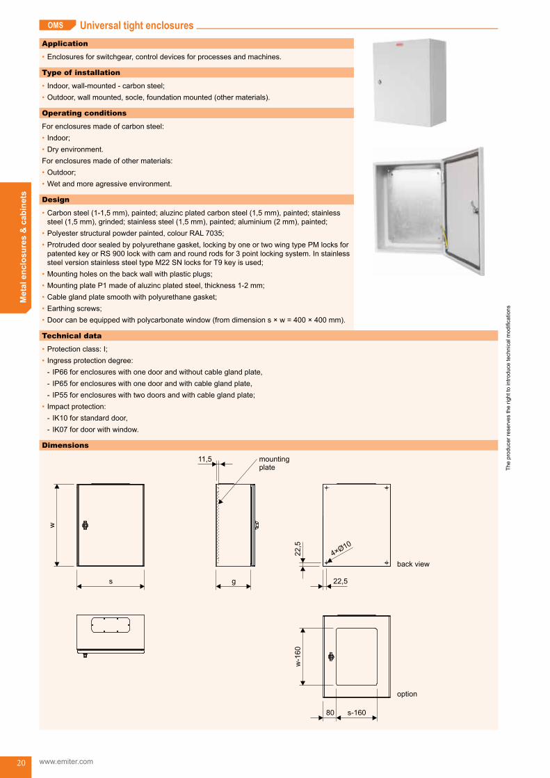
Universal tight enclosuresOMS
Application
•Enclosuresforswitchgear,controldevicesforprocessesandmachines.
Type of installation
•Indoor,wall-mounted-carbonsteel;•Outdoor,wallmounted,socle,foundationmounted(othermaterials).
Operating conditions
Forenclosuresmadeofcarbonsteel:•Indoor;•Dryenvironment.Forenclosuresmadeofothermaterials:•Outdoor;•Wetandmoreagressiveenvironment.
Design
•Carbonsteel(1-1,5mm),painted;aluzincplatedcarbonsteel(1,5mm),painted;stainlesssteel(1,5mm),grinded;stainlesssteel(1,5mm),painted;aluminium(2mm),painted;
•Polyesterstructuralpowderpainted,colourRAL7035;•Protrudeddoorsealedbypolyurethanegasket,lockingbyoneortwowingtypePMlocksforpatentedkeyorRS900lockwithcamandroundrodsfor3pointlockingsystem.InstainlesssteelversionstainlesssteeltypeM22SNlocksforT9keyisused;
•Mountingholesonthebackwallwithplasticplugs;•MountingplateP1madeofaluzincplatedsteel,thickness1-2mm;•Cableglandplatesmoothwithpolyurethanegasket;•Earthingscrews;•Doorcanbeequippedwithpolycarbonatewindow(fromdimensions×w=400×400mm).
Dimensions
back view
22,5
22,5
410
×Ø
11,5
g
mountingplate
w-1
60
s-16080
option
s
w
Technical data
•Protectionclass:I;•Ingressprotectiondegree:
- IP66forenclosureswithonedoorandwithoutcableglandplate, - IP65forenclosureswithonedoorandwithcableglandplate, - IP55forenclosureswithtwodoorsandwithcableglandplate;
•Impactprotection: - IK10 for standard door, - IK07fordoorwithwindow.
Universal tight enclosures (OMS) OMS_start

The
prod
ucer
rese
rves
the
right
to in
trodu
ce te
chni
cal m
odifi
catio
ns
Met
al e
nclo
sure
s &
cab
inet
s
21
OMS
Reference chart
type
dimensions [mm] dimensions of cable gland
plates*[mm]
carbon steelsheetthickness
[mm]
number of locks
mounting plate dimensions
[mm]s w g
OMS 25 25 15 250 250 150 90×180 1 1 190×190OMS 20 30 15 200 300 150 90×180 1 1 140×240OMS 30 20 15 300 200 150 90×150 1 1 240×140OMS 30 30 15 300 300 150 90×230 1 1 240×240OMS 30 30 21 300 300 210 90×230 1 1 240×240OMS 30 40 15 300 400 150 90×230 1 1 240×340OMS 30 40 21 300 400 210 90×230 1 1 240×340OMS 40 50 21 400 500 210 90×230 1 1 340×440OMS 40 30 15 400 300 150 90×230 1 1 340×240OMS 40 40 21 400 400 210 90×330 1 1 340×340OMS 40 40 30 400 400 300 90×230 1 1 340×340OMS 30 50 21 300 500 210 150×330 1,2 1 240×440OMS 40 60 21 400 600 210 150×330 1,2 1 340×540OMS 40 60 30 400 600 300 150×330 1,2 1 340×540OMS 50 40 30 500 400 300 150×330 1,2 1 440×340OMS 50 50 21 500 500 210 150×420 1,2 1 440×340OMS 50 50 30 500 500 300 150×420 1,2 1 440×440OMS 50 60 21 500 600 210 150×420 1,2 1 440×440OMS 50 60 30 500 600 300 150×420 1,2 1 440×540OMS 60 40 21 600 400 210 150×420 1,2 1 440×540OMS 60 40 30 600 400 300 150×420 1,2 1 540×340OMS 60 50 21 600 500 210 150×520 1,2 1 540×340OMS 60 50 30 600 500 300 150×520 1,2 1 540×440OMS 60 60 21 600 600 210 150×520 1,2 1 540×440OMS 60 60 30 600 600 300 150×520 1,2 1 540×540OMS 60 80 21 600 800 210 150×520 1,5 2 540×540OMS 60 80 30 600 800 300 150×520 1,5 2 540×740OMS 60 80 40 600 800 400 150×520 1,5 2 540×740OMS 60 100 30 600 1000 300 150×520 1,5 3p 540×740OMS 60 120 30 600 1200 300 150×520 1,5 3p 540×940OMS 80 60 21 800 600 210 150×520 1,5 1 540×1140OMS 80 60 30 800 600 300 150×520 1,5 1 740×540OMS 80 80 21 800 800 210 150×520 1,5 2 740×540OMS 80 80 30 800 800 300 150×520 1,5 2 740×740OMS 80 100 21 800 1000 210 150×520 1,5 3p 740×940OMS 80 120 30 800 1200 300 150×520 1,5 3p 740×1140OMS 80 100 40 800 1000 400 150×520 1,5 3p 740×940OMS 80 120 30 800 1200 300 150×520 1,5 3p 740×1140OMS 100 120 25 1000 1200 250 150×520 1,5 3p 940×1140OMS 100 140 25 1000 1400 250 150×520 1,5 3p 940×1340
*cableglandplateisfixedtothehousingbythescrews
The
prod
ucer
rese
rves
the
right
to in
trodu
ce te
chni
cal m
odifi
catio
ns
www.emiter.com
Met
al e
nclo
sure
s &
cab
inet
s
22
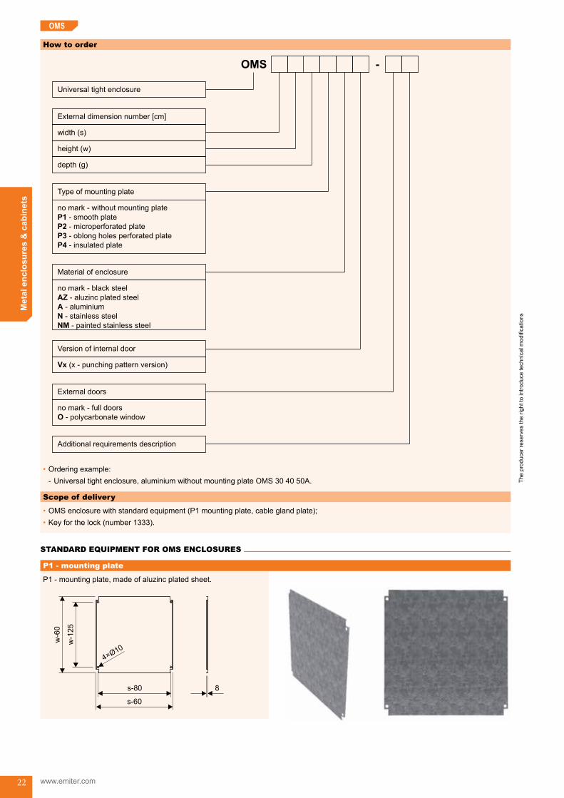
P1-mountingplate,madeofaluzincplatedsheet.
w-1
25
w-6
0
s-80
s-60
410
×Ø
8
OMS
How to order
OMS
Universal tight enclosure
width (s)
height (w)
External dimension number [cm]
depth (g)
Type of mounting plate
no mark - without mounting plate
- smooth plate
- microperforated plate
- oblong holes perforated plate
- insulated plate
P1
P2
P3
P4
External doors
-
Additional requirements description
no mark - full doors
polycarbonate windowO -
Version of internal door
Vx (x - punching pattern version)
Material of enclosure
no mark - black steel
- aluzinc plated steel
- aluminium
- stainless steel
- painted stainless steel
AZ
A
N
NM
•Orderingexample: - Universaltightenclosure,aluminiumwithoutmountingplateOMS304050A.
Scope of delivery
•OMSenclosurewithstandardequipment(P1mountingplate,cableglandplate);•Keyforthelock(number1333).
STANDARD EQUIPMENT FOR OMS ENCLOSURES
P1 - mounting plate
Standard equipment for OMS enclosures
The
prod
ucer
rese
rves
the
right
to in
trodu
ce te
chni
cal m
odifi
catio
ns
Met
al e
nclo
sure
s &
cab
inet
s
23
OMS
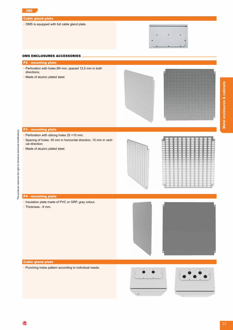
•PerforationwithholesØ4mm,spaced12,5mminbothdirections;
•Madeofaluzincplatedsteel.
•Perforationwithoblongholes25×10mm;•Spacingofholes:35mminhorizontaldirection,15mminverti-caldirection;
•Madeofaluzincplatedsteel.
•InsulationplatemadeofPVCorGRP,graycolour;•Thickness-6mm.
•Punchingholespatternaccordingtoindividualneeds.
OMS ENCLOSURES ACCESSORIES
•OMSisequippedwithfullcableglandplate.
Cable gland plate
P2 - mounting plate
P3 - mounting plate
P4 - mounting plate
Cable gland plate
OMS enclosures accessories

The
prod
ucer
rese
rves
the
right
to in
trodu
ce te
chni
cal m
odifi
catio
ns
www.emiter.com
Met
al e
nclo
sure
s &
cab
inet
s
24
•Theordermustspecify: - throttlingrange(cablediameter), - IP degree, - temperature range, - typeofmaterial.
OMS
Rubber, membrane gland plate (mounted on cable gland plate)Type of membrane gland plate
type IP cable diameter range [mm] temperature range colour picture
MC 3 652×Ø24-541×Ø30-604×Ø8-16
-40 to 100ºC RAL 7035
MC 25 65
1×Ø20-2612×Ø10-144×Ø5-74×Ø14-204×Ø8-12
-40 to 100ºC RAL 7035
MC 35 65
1×Ø17-3216×Ø10-142×Ø6-102×Ø12-1814×Ø8-12
-40 to 100ºC RAL 7035
MC 10-30 65 8×Ø10-302×Ø7-12 -40 to 100ºC RAL 7035
How to order
•Cableglandplate-MC3type.
General information
•RubberglandsBDEaremadeofSBR+NRrubber;•Intendedforsealingthecablepassagethroughthewallofenclosureofelectricaldevices;•Availableinblackcolour(RAL9004);•IPdegree-min.IP30;•Temperaturerange:-40to85ºC.
Dimensions
Ød
ØD
L
A2
Cable glands
Rubber glands - BDE

The
prod
ucer
rese
rves
the
right
to in
trodu
ce te
chni
cal m
odifi
catio
ns
Met
al e
nclo
sure
s &
cab
inet
s
25
OMS
Reference chart
typedimensions [mm] holediameterin
lamina [mm] cable diameter [mm]A D d L
BDE 11 4 24 7 30 16,5 6 - 8BDE 13 6 31 8 23 21 9 - 12BDE 16 6 34 10,5 23 23 11 - 15BDE 21 6 42 13,5 25 29 14 - 18BDE 29 7 50 17 30 38 18 - 25BDE 36 8 62 22 34 48 24 - 34BDE 42 8 63 31 39 55 31 - 44BDE 48 8 72 41 45 65 40 - 54BDE 54 8 85 51 50 78 52 - 66BDE 67 8 97 63 63 90 65 - 78
How to order
•BDE29typerubbergland.
General information
•Internaldoorsarefixedtotherightsideofthecaseandarelockedbywinglock;•Possibilityofpunchingholesfordevicesaccordingtoagreedpattern.
How to order
•Aftertheenclosurecodesymbols,denotingthedimensionsortypeofmaterial,typetheletter„Vx”, eg OMS 40 60 30 Vx.
- letter V means smooth internal doors - letters Vx mean doors punched with x type agreed pattern
Application
•CWsocleforOMStypeenclosuresisdesignedtobefixedtosmooth,hardenedsurfaces.
Type of installation
•OMSenclosuresarefastenedtothesoclebyroundheadsquareneckbolts.
Design
•Socleismadeofthesamematerialastheenclosureandisplatedsteelsheet,paintedwithpowderpolyesterpaint,colourRAL7035(orgrindedforstainlesssteel).Socleelementsareformedfromsheetandfastenedtogetherbyriveting.Frontpartisequippedwithrevisiondoorlockedbywinglock(PM*type).
Technical data
•Ingressprotection-IP44;•Impactprotection-IK10.
* Key for the lock (number 1333).
Internal door
Free-standing socles - CW type
The
prod
ucer
rese
rves
the
right
to in
trodu
ce te
chni
cal m
odifi
catio
ns
www.emiter.com
Met
al e
nclo
sure
s &
cab
inet
s
26
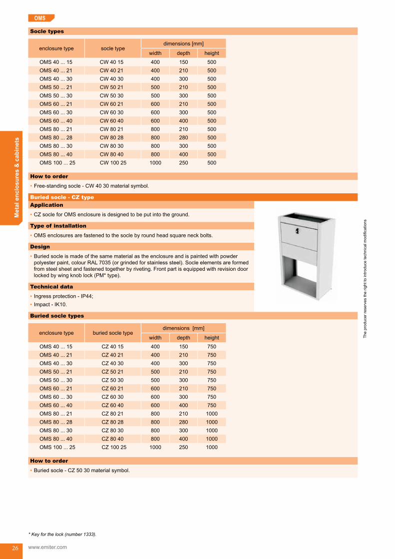
Socle types
enclosure type socle typedimensions [mm]
width depth height
OMS40...15 CW 40 15 400 150 500OMS40...21 CW 40 21 400 210 500OMS40...30 CW 40 30 400 300 500OMS50...21 CW 50 21 500 210 500OMS50...30 CW 50 30 500 300 500OMS60...21 CW 60 21 600 210 500OMS60...30 CW 60 30 600 300 500OMS60...40 CW 60 40 600 400 500OMS80...21 CW 80 21 800 210 500OMS80...28 CW 80 28 800 280 500OMS80...30 CW 80 30 800 300 500OMS80...40 CW 80 40 800 400 500OMS100...25 CW 100 25 1000 250 500
How to order
•Free-standingsocle-CW4030materialsymbol.
Application
•CZsocleforOMSenclosureisdesignedtobeputintotheground.
Type of installation
•OMSenclosuresarefastenedtothesoclebyroundheadsquareneckbolts.
Design
•Buriedsocleismadeofthesamematerialastheenclosureandispaintedwithpowderpolyesterpaint,colourRAL7035(orgrindedforstainlesssteel).Socleelementsareformedfromsteelsheetandfastenedtogetherbyriveting.Frontpartisequippedwithrevisiondoorlockedbywingknoblock(PM*type).
Technical data
•Ingressprotection-IP44;•Impact-IK10.
* Key for the lock (number 1333).
OMS
Buried socle - CZ type
Buried socle types
enclosure type buried socle typedimensions [mm]
width depth height
OMS40...15 CZ 40 15 400 150 750OMS40...21 CZ 40 21 400 210 750OMS40...30 CZ 40 30 400 300 750OMS50...21 CZ 50 21 500 210 750OMS50...30 CZ 50 30 500 300 750OMS60...21 CZ 60 21 600 210 750OMS60...30 CZ 60 30 600 300 750OMS60...40 CZ 60 40 600 400 750OMS80...21 CZ 80 21 800 210 1000OMS80...28 CZ 80 28 800 280 1000OMS80...30 CZ 80 30 800 300 1000OMS80...40 CZ 80 40 800 400 1000OMS100...25 CZ 100 25 1000 250 1000
How to order
•Buriedsocle-CZ5030materialsymbol.

The
prod
ucer
rese
rves
the
right
to in
trodu
ce te
chni
cal m
odifi
catio
ns
Met
al e
nclo
sure
s &
cab
inet
s
27
OMS
Application
•Forfasteningenclosurestothewall.
Design
•Wallmountingkitconsistsof: - bracket (MZ2259), - M8×10 screw, - nut(M1971).
How to order
•WallmountingbracketkitMZ2259.
Application
•FortightenclosuresOMStype,destinedforoutdoorapplication.Mountedontheoriginalflatroofofenclosureandfixedbynuts.
Design
•Madeofthesamematerialasenclosure.
Wall mounting bracket
Single slope roof for OMS enclosures - DMS type
Dimensions
Reference chart
enclosure type roof typedimensions [mm]
width depth height
OMS20...15 DMS 20 15 220 190
80/40
OMS25...15 DMS 25 15 270 190OMS30...15 DMS 30 15 320 190OMS30...21 DMS 30 21 320 250OMS40...15 DMS 40 15 420 190OMS40...21 DMS 40 21 420 250OMS40...30 DMS 40 30 420 340OMS50...21 DMS 50 21 520 250OMS50...30 DMS 50 30 520 340OMS60...21 DMS 60 21 620 250OMS60...30 DMS 60 30 620 340OMS60...40 DMS 60 40 620 440OMS80...21 DMS 80 21 820 250OMS80...28 DMS 80 28 820 320OMS80...30 DMS 80 30 820 340OMS80...40 DMS 80 40 820 440OMS100...25 DMS 100 25 1020 290 NOTE: Roof is factory mounted on the OMS enclosures
on request.
OMS_end
The
prod
ucer
rese
rves
the
right
to in
trodu
ce te
chni
cal m
odifi
catio
ns
www.emiter.com
Met
al e
nclo
sure
s &
cab
inet
s
28
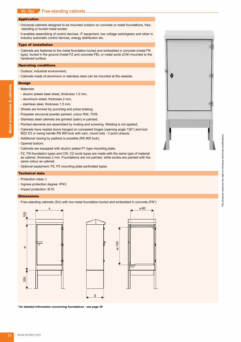
Free-standing cabinetsApplication
•Universal cabinets designed to be mounted outdoor on concrete or metal foundations, free--standingorburiedmetalsocles;
•Itenablesassemblingofcontroldevices,ITequipment,lowvoltageswitchgearsandotherinindustryautomaticcontroldevices,energydistributionetc.
Type of installation
•Cabinetsarefastenedtothemetalfoundationburiedandembeddedinconcrete(metalFNtype),buriedintheground(metalFZandconcreteFB),ormetalsocle(CW)mountedtothehardenedsurface.
Operating conditions
•Outdoor,industrialenvironment;•Cabinetsmadeofaluminiumorstainlesssteelcanbemountedattheseaside.
Design
•Materials: - aluzincplatedsteelsheet,thickness1,5mm, - aluminiumsheet,thickness2mm, - stainlesssteel,thickness1,5mm.
•Sheetsareformedbypunchingandpressbraking;•Polyesterstructuralpowderpainted,colourRAL7035;•Stainlesssteelcabinetsaregrinded(satin)orpainted;•Paintedelementsareassembledbyrivetingandscrewing.Weldingisnotapplied;•Cabinetshavenesteddoorshangedonconcealedhinges(openingangle130°)andlockM22D3orswinghandleRS900lockwithcam,roundrods-3pointclosure;
•Additionalclosingbypadlockispossible(RS900lock);•Openedbottom;•CabinetsareequippedwithaluzincplatedP1typemountingplate;•FZ,FNfoundationtypesandCW,CZsocletypesaremadewiththesametypeofmaterialascabinet,thickness2mm.Foundationsarenotpainted,whilesoclesarepaintedwiththesamecolourascabinet;
•Optionalequipment:P2,P3mountingplateperforatedtypes.
Dimensions
•Free-standingcabinets(SU)withlowmetalfoundationburiedandembeddedinconcrete(FN*)
g
s
w350
100
s-80
w-1
45
* for detailed information concerning foundations - see page 36
SU • SUJ
Technical data
•Protectionclass:I;•Ingressprotectiondegree:IP43;•Impactprotection:IK10.
Free-standing cabinets (SU, SUJ) SU_start
The
prod
ucer
rese
rves
the
right
to in
trodu
ce te
chni
cal m
odifi
catio
ns
Met
al e
nclo
sure
s &
cab
inet
s
29
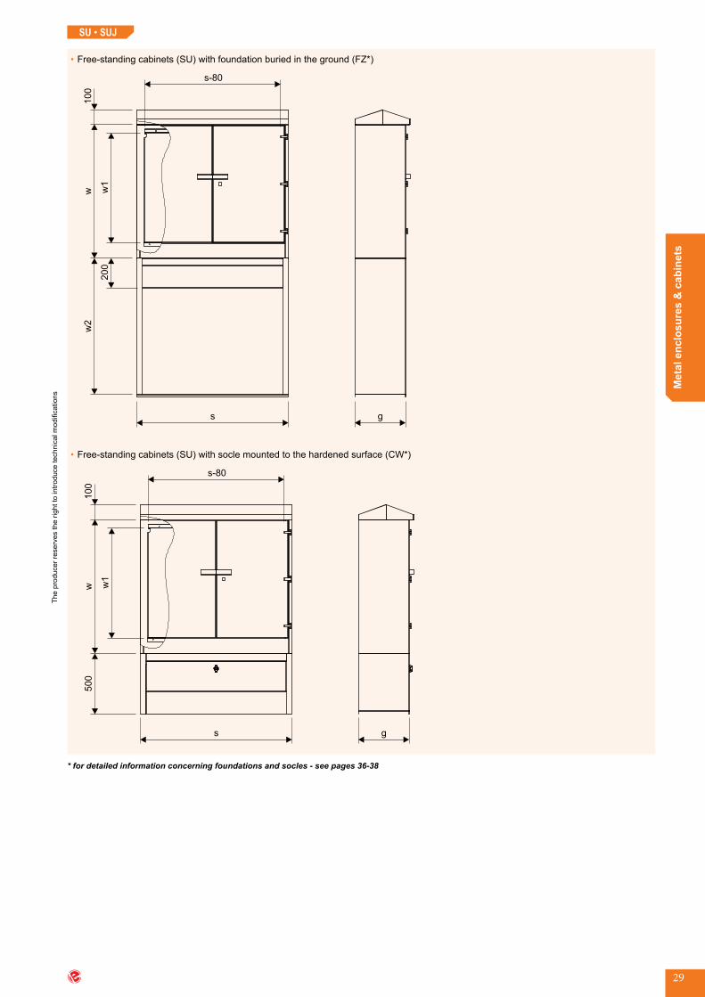
•Free-standingcabinets(SU)withfoundationburiedintheground(FZ*)
s
s-80w
w2
100
w1
g
200
•Free-standingcabinets(SU)withsoclemountedtothehardenedsurface(CW*)
s
s-80
w500
100
w1
g
* for detailed information concerning foundations and socles - see pages 36-38
SU • SUJ

The
prod
ucer
rese
rves
the
right
to in
trodu
ce te
chni
cal m
odifi
catio
ns
www.emiter.com
Met
al e
nclo
sure
s &
cab
inet
s
30
•Free-standingcabinets(SU)withsocleburiedintheground(CZ*)
s
s-80w
w2
100
w1
g
400
•Free-standingcabinets(SU)withconcretefoundation(FB*)
s
w1050
100
w-1
45
s-80
g
* for detailed information concerning foundations and socles - see pages 39-41
SU • SUJ

The
prod
ucer
rese
rves
the
right
to in
trodu
ce te
chni
cal m
odifi
catio
ns
Met
al e
nclo
sure
s &
cab
inet
s
31
Reference chart
cabinet type
dimensions [mm]
type of roofnumber of door wings
type of lock**
foundation / socle type
low founda-
tion FN*
buried founda-
tion FZ*
surface mounted
socle CW*
buried socle
CZ*
concrete founda-
tion FB*
s w g
SU 28 88 33 280 880 335 apex 1 M22 + + + + -SUJ 28 88 33 280 880 335 slope 1 M22 + + + + -SU 53 88 33 530 880 335 apex 1 M22 + + + + -SUJ 53 88 33 530 880 335 slope 1 M22 + + + + -SU 80 88 33 800 880 335 apex 1 M22 + + + + -SUJ 80 88 33 800 880 335 slope 1 M22 + + + + -SU 100 88 33 1000 880 335 apex 2 M22 + + + + -SUJ 100 88 33 1000 880 335 slope 2 M22 + + + + -SU 100 88 43 1000 880 435 apex 2 M22 + + + + -SUJ 100 88 43 1000 880 435 slope 2 M22 + + + + -SU 40 95 32 400 950 320 apex 1 RS 900 - + + + +SU 60 95 32 600 950 320 apex 1 RS 900 - + + + +SU 80 95 32 800 950 320 apex 1 RS 900 - + + + +SU 90 95 32 900 950 320 apex 2 RS 900 - + + + +SU 95 95 32 950 950 320 apex 2 RS 900 - + + + -SU 100 95 32 1000 950 320 apex 2 RS 900 - + + + +SU 105 95 32 1050 950 320 apex 2 RS 900 - + + + +SU 40 115 40 400 1150 400 apex 1 RS 900 - + + + +SU 60 115 40 600 1150 400 apex 1 RS 900 - + + + +SU 70 115 40 700 1150 400 apex 1 RS 900 - + + + -SU 80 115 40 800 1150 400 apex 1 RS 900 - + + + +SU 85 115 40 850 1150 400 apex 1 RS 900 - + + + +SU 90 115 40 900 1150 400 apex 2 RS 900 - + + + -SU 95 115 40 950 1150 400 apex 2 RS 900 - + + + -SU 100 115 40 1000 1150 400 apex 2 RS 900 - + + + +SU 105 115 40 1050 1150 400 apex 2 RS 900 - + + + +SU 120 115 40 1200 1150 400 apex 2 RS 900 - + + + -SU 80 120 50 800 1200 500 apex 1 RS 900 - + + + -SU 110 120 50 1100 1200 500 apex 2 RS 900 - + + + -SU 100 140 60 1000 1400 600 apex 2 RS 900 - + + + -SU 100 200 50 1000 2000 500 apex 2 RS 900 - + + + -SU 120 200 50 1200 2000 500 apex 2 RS 900 - + + + -
** for detailed information concerning foundations and socles - see pages 36-41** for detailed information concerning types of locks and types of keys - see page 134
SU • SUJ

The
prod
ucer
rese
rves
the
right
to in
trodu
ce te
chni
cal m
odifi
catio
ns
www.emiter.com
Met
al e
nclo
sure
s &
cab
inet
s
32
Reference chart
cabinet type
foundation / socle type
low foundation
FN*
buried foundation
FZ*
surface mounted socleCW*
buried socle
CZ*
concrete foundation
FB*SU 28 88 33 FN 28 33 FZ 28 33 90 CW 28 33 CZ 28 33 90 -SUJ 28 88 33 FN 28 33 FZ 28 33 90 CW 28 33 CZ 28 33 90 -SU 53 88 33 FN 53 33 FZ 53 33 90 CW 53 33 CZ 53 33 90 -SUJ 53 88 33 FN 53 33 FZ 53 33 90 CW 53 33 CZ 53 33 90 -SU 80 88 33 FN 80 33 FZ 80 33 90 CW 80 33 CZ 80 33 90 -SUJ 80 88 33 FN 80 33 FZ 80 33 90 CW 80 33 CZ 80 33 90 -SU 100 88 33 FN 100 33 FZ 100 33 90 CW 100 33 CZ 100 33 90 -SUJ 100 88 33 FN 100 33 FZ 100 33 90 CW 100 33 CZ 100 33 90 -SU 100 88 43 FN 100 43 FZ 100 43 90 CW 100 43 CZ 100 43 90 -SUJ 100 88 43 FN 100 43 FZ 100 43 90 CW 100 43 CZ 100 43 90 -SU 40 95 32 - FZ 40 32 90 CW 40 32 CZ 40 32 90 FB 40 32SU 60 95 32 - FZ 60 32 90 CW 60 32 CZ 60 32 90 FB 60 32SU 80 95 32 - FZ 80 32 90 CW 80 32 CZ 80 32 90 FB 80 32SU 90 95 32 - FZ 90 32 90 CW 90 32 CZ 90 32 90 FB 80 32SU 95 95 32 - FZ 95 32 90 CW 95 32 CZ 95 32 90 -SU 100 95 32 - FZ 100 32 90 CW 100 32 CZ 100 32 90 FB 105 32ASU 105 95 32 - FZ 105 32 90 CW 105 32 CZ 105 32 90 FB 105 32SU 40 115 40 - FZ 40 40 90 CW 40 40 CZ 40 40 90 FB 40 40SU 60 115 40 - FZ 60 40 90 CW 60 40 CZ 60 40 90 FB 60 40SU 70 115 40 - FZ 70 40 90 CW 70 40 CZ 70 40 90 -SU 80 115 40 - FZ 80 40 90 CW 80 40 CZ 80 40 90 FB 80 40SU 85 115 40 - FZ 85 40 90 CW 85 40 CZ 85 40 90 FB 85 40SU 90 115 40 - FZ 90 40 90 CW 90 40 CZ 90 40 90 -SU 95 115 40 - FZ 95 40 90 CW 95 40 CZ 95 40 90 -SU 100 115 40 - FZ 100 40 90 CW 100 40 CZ 100 40 90 FB 105 40ASU 105 115 40 - FZ 105 40 90 CW 105 40 CZ 105 40 90 FB 105 40SU 120 115 40 - FZ 120 40 90 CW 120 40 CZ 120 40 90 -SU 80 120 50 - FZ 80 50 90 CW 80 50 CZ 80 50 90 -SU 110 120 50 - FZ 110 50 90 CW 110 50 CZ 110 50 90 -SU 100 140 60 - FZ 100 60 120 CW 100 60 CZ 100 60 120 -SU 100 200 50 - FZ 100 50 120 CW 100 50 CZ 100 50 120 -SU 120 200 50 - FZ 120 50 120 CW 120 50 CZ 120 50 120 -
* for detailed information concerning foundations and socles - see pages 36-41
SU • SUJ
The
prod
ucer
rese
rves
the
right
to in
trodu
ce te
chni
cal m
odifi
catio
ns
Met
al e
nclo
sure
s &
cab
inet
s
33
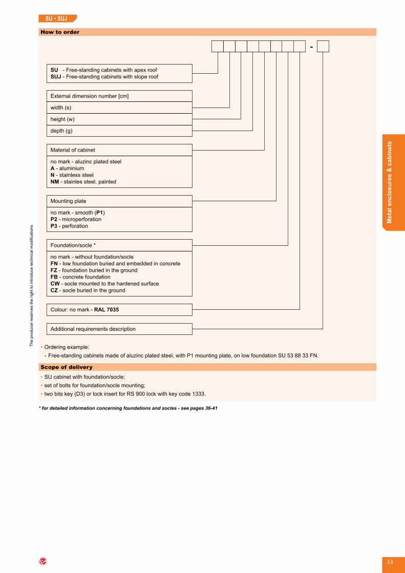
How to order
SU
SUJ
width (s)
height (w)
External dimension number [cm]
depth (g)
Additional requirements description
- Free-standing cabinets with apex roof
- Free-standing cabinets with slope roof
no mark - aluzinc plated steel
- aluminium
- stainless steel
- stainles steel, painted
A
N
NM
Material of cabinet
no mark - smooth ( )
- microperforation
- perforation
P1
P2
P3
Mounting plate
no mark - without foundation/socle
- low foundation buried and embedded in concrete
-
-
FN
FZ
FB
foundation buried in the ground
concrete foundation
- socle mounted to the hardened surface
- socle buried in the ground
CW
CZ
Foundation/socle *
Colour: no mark - RAL 7035
-
•Orderingexample: - Free-standingcabinetsmadeofaluzincplatedsteel,withP1mountingplate,onlowfoundationSU538833FN.
Scope of delivery
•SUcabinetwithfoundation/socle;•setofboltsforfoundation/soclemounting;•twobitskey(D3)orlockinsertforRS900lockwithkeycode1333.
* for detailed information concerning foundations and socles - see pages 36-41
SU • SUJ
SU_end
The
prod
ucer
rese
rves
the
right
to in
trodu
ce te
chni
cal m
odifi
catio
ns
www.emiter.com
Met
al e
nclo
sure
s &
cab
inet
s
34
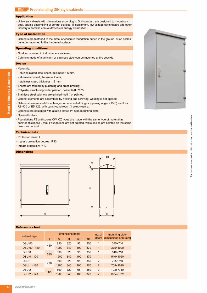
Free-standing DIN style cabinetsDSU
Application
•UniversalcabinetswithdimensionsaccordingtoDINstandardaredesignedtomountout- door,enableassemblingofcontroldevices,ITequipment,lowvoltageswitchgearsandotherindustryautomaticcontroldevicesorenergydistribution.
Type of installation
•Cabinetsarefastenedtothemetalorconcretefoundationburiedintheground,oronsoclesburiedormountedtothehardenedsurface.
Operating conditions
•Outdoormountedinindustrialenvironment;•Cabinetsmadeofaluminiumorstainlesssteelcanbemountedattheseaside.
Design
•Materials: - aluzincplatedsteelsheet,thickness1,5mm, - aluminiumsheet,thickness2mm, - stainlesssteel,thickness1,5mm;
•Sheetsareformedbypunchingandpressbraking;•Polyesterstructuralpowderpainted,colourRAL7035;•Stainlesssteelcabinetsaregrinded(satin)orpainted;•Cabinetelementsareassembledbyrivetingandscreving,weldingisnotapplied;•Cabinetshavenesteddoorshangedonconcealedhinges(openingangle-130º)andlockRS900orED125,withcam,roundrods-3pointclosure;
•CabinetsareequippedwithaluzincplatedP1typemountingplate;•Openedbottom;•FoundationsFZandsoclesCW,CZtypesaremadewiththesametypeofmaterialascabinet,thickness2mm.Foundationsarenotpainted,whilesoclesarepaintedonthesamecolourascabinet.
Technical data
•Protectionclass:I;•Ingressprotectiondegree:IP43;•Impactprotection:IK10.
Dimensions
s g
ww
1
g1
Reference chart
cabinet typedimensions [mm] no.of
doorsmounting plate
dimensions a×b [mm]s w g w1 g1
DSU 00460
890 320 95 350 1 375×710DSU 00 - 120 1200 340 100 370 1 375×1020DSU 0
595890 320 95 350 1 510×710
DSU 0 - 120 1200 340 100 370 1 510×1020DSU 1
790890 320 95 350 2 705×710
DSU 1 - 120 1200 340 100 370 2 705×1020DSU 2
1120890 320 95 350 2 1035×710
DSU 2 - 120 1200 340 100 370 2 1034×1020
Free-standing DIN style cabinets (DSU) DSU_start
The
prod
ucer
rese
rves
the
right
to in
trodu
ce te
chni
cal m
odifi
catio
ns
Met
al e
nclo
sure
s &
cab
inet
s
35
DSU
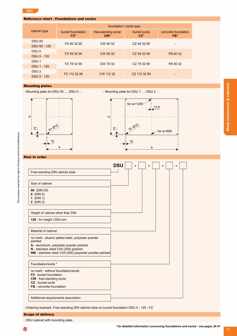
Reference chart - Foundations and socles
cabinet typefoundation / socle type
buried foundationFZ*
free-standing socleCW*
buried socle CZ*
concrete foundation FB*
DSU 00FZ 46 32 90 CW 46 32 CZ 46 32 90 -
DSU 00 - 120DSU 0
FZ 59 32 90 CW 59 32 CZ 59 32 90 FB 60 32DSU 0 - 120DSU 1
FZ 79 32 90 CW 79 32 CZ 79 32 90 FB 80 32DSU 1 - 120DSU 2
FZ 112 32 90 CW 112 32 CZ 112 32 90 -DSU 2 - 120
Mounting plates
•MountingplateforDSU00...,DSU0...
b
15
a
15
410
× Ø
•MountingplateforDSU1...,DSU2...
6×10
Ø
for w=890
a
15
b
15
12,5for w=1200
* for detailed information concerning foundations and socles - see pages 36-41
How to order
DSU - - -
Size of cabinet
00
0
1
2
(DIN 00)
(DIN 0)
(DIN 1)
(DIN 2)
Height of cabinet other than DIN
120 - for height 1200 mm
Material of cabinet
no mark - aluzinc plated steel, polyester powderpainted
Free-standing DIN stylecabinet
-
Additional requirements description
A - aluminium, polyester powder painted
- stainless steel V2A (304) grained
- stainless steel V2A (304) polyester powder painted
N
NM
no mark - without foundation/socle
-FZ buried foundation
- free-standing socle
- buried socle
- concrete foundation
CW
CZ
FB
Foundation/socle *
•Orderingexample:Free-standingDINcabinetstyleonburiedfoundationDSU0-120-FZ.
Scope of delivery
•DSUcabinetwithmountingplate.
DSU_end

The
prod
ucer
rese
rves
the
right
to in
trodu
ce te
chni
cal m
odifi
catio
ns
www.emiter.com
Met
al e
nclo
sure
s &
cab
inet
s
36
Foundations and socles for cabinets type SU, SUJ, DSUFN • FZ • CW • CZ • FB
Application
•FoundationburiedandembeddedinconcreteandformountingSU,SUJ,DSUcabinets.
Type of installation
•CabinetisfixedtothefoundationusingM8bolts.
Design
•Foundationismadeofmetalsheet: - aluzincplated,thickness2mm, - aluminium,thickness2mm, - stainlesssteel,thickness1,5mm;
•Elementsoffoundationarefixedtogetherbyriveting;•Foundationsmadeofaluminiumarepaintedoncabinetcolour.
Application
•FoundationburiedinthegroundformountingSU,SUJ,DSUcabinets.
Type of installation
•CabinetisfixedtothefoundationusingM8bolts.
Design
•Foundationismadeofmetalsheet: - aluzincplated,thickness2mm, - aluminium,thickness2mm, - stainlesssteel,thickness1,5mm;
•Elementsoffoundationsarefixedtogetherbyriveting;•Foundationsmadeofaluminiumarepaintedincabinetcolour.
Reference chart
foundation typedimensions [mm]
materials g
FN 28 33 280 335 no mark - aluzinc plated steel, unpainted;A-aluminium,painted;N-stainlesssteelsheet;NM-stainlesssteelsheet,painted;
FN 53 33 535 335FN 80 33 800 335FN 100 33 1000 335FN 100 43 1000 435
•Orderingexample: - Low steel foundation FN8033.
Steel low foundation FN type
Dimensions
s
350
g
Buried foundations FZ type
Dimensions
s
w1
g
fund/cokFoundations and socles for cabinets type SU, SUJ, DSU (FN, FZ, CW, CZ, FB)
The
prod
ucer
rese
rves
the
right
to in
trodu
ce te
chni
cal m
odifi
catio
ns
Met
al e
nclo
sure
s &
cab
inet
s
37
FN • FZ • CW • CZ • FB
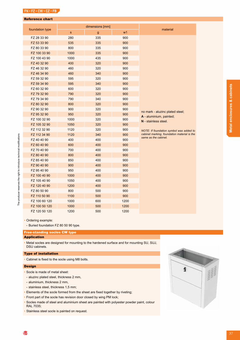
Reference chart
foundation typedimensions [mm]
materials g w1
FZ 28 33 90 280 335 900
nomark-aluzincplatedsteel;A-aluminium,painted;N-stainlesssteel.
NOTE: If foundation symbol was added to cabinet marking, foundation material is the same as the cabinet.
FZ 53 33 90 535 335 900FZ 80 33 90 800 335 900FZ 100 33 90 1000 335 900FZ 100 43 90 1000 435 900FZ 40 32 90 400 320 900FZ 46 32 90 460 320 900FZ 46 34 90 460 340 900FZ 59 32 90 595 320 900FZ 59 34 90 595 340 900FZ 60 32 90 600 320 900FZ 79 32 90 790 320 900FZ 79 34 90 790 340 900FZ 80 32 90 800 320 900FZ 90 32 90 900 320 900FZ 95 32 90 950 320 900FZ 100 32 90 1000 320 900FZ 105 32 90 1050 320 900FZ 112 32 90 1120 320 900FZ 112 34 90 1120 340 900FZ 40 40 90 400 400 900FZ 60 40 90 600 400 900FZ 70 40 90 700 400 900FZ 80 40 90 800 400 900FZ 85 40 90 850 400 900FZ 90 40 90 900 400 900FZ 95 40 90 950 400 900FZ 100 40 90 1000 400 900FZ 105 40 90 1050 400 900FZ 120 40 90 1200 400 900FZ 80 50 90 800 500 900FZ 110 50 90 1100 500 900FZ 100 60 120 1000 600 1200FZ 100 50 120 1000 500 1200FZ 120 50 120 1200 500 1200
•Orderingexample: - BuriedfoundationFZ805090type.
Application
•MetalsoclesaredesignedformountingtothehardenedsurfaceandformountingSU,SUJ,DSUcabinets.
Type of installation
•CabinetisfixedtothesocleusingM8bolts.
Design
•Socleismadeofmetalsheet: - aluzincplatedsteel,thickness2mm, - aluminium,thickness2mm, - stainlesssteel,thickness1,5mm;
•Elementsofthesocleformedfromthesheetarefixedtogetherbyriveting;•FrontpartofthesoclehasrevisiondoorclosedbywingPMlock;•Soclesmadeofsteelandaluminiumsheetarepaintedwithpolyesterpowderpaint,colourRAL7035;
•Stainlesssteelsocleispaintedonrequest.
Free-standing socles CW type
FZ

The
prod
ucer
rese
rves
the
right
to in
trodu
ce te
chni
cal m
odifi
catio
ns
www.emiter.com
Met
al e
nclo
sure
s &
cab
inet
s
38
FN • FZ • CW • CZ • FB
Reference chart
socle typedimensions [mm]
materials g
CW 28 33 280 335
no mark - aluzinc plated steel, painted;A-aluminium,painted;N-stainlesssteel;NM-stainlesssteel,painted.
NOTE: If socle symbol was added to cabi-net marking, socle material is the same as the cabinet.
CW 53 33 535 335CW 80 33 800 335CW 100 33 1000 335CW 100 43 1000 435CW 40 32 400 320CW 46 32 460 320CW 46 34 460 340CW 59 32 595 320CW 59 34 595 340CW 60 32 600 320CW 79 32 790 320CW 79 34 790 340CW 80 32 800 320CW 90 32 900 320CW 95 32 950 320CW 100 32 1000 320CW 105 32 1050 320CW 112 32 1120 320CW 112 34 1120 340CW 40 40 400 400CW 60 40 600 400CW 70 40 700 400CW 80 40 800 400CW 85 40 850 400CW 90 40 900 400CW 95 40 950 400CW 100 40 1000 400CW 105 40 1050 400CW 120 40 1200 400CW 80 50 800 500CW 110 50 1100 500CW 100 60 1000 600CW 100 50 1000 500CW 120 50 1200 500
•Orderingexample: - Free-standingsocleCW10050type.
Dimensions
s
50
0
g
Technical data
•Protectionclass:I;•Ingressprotectiondegree:IP30;•Impactprotection:IK10.
fund/cok-end

The
prod
ucer
rese
rves
the
right
to in
trodu
ce te
chni
cal m
odifi
catio
ns
Met
al e
nclo
sure
s &
cab
inet
s
39
FN • FZ • CW • CZ • FB
Dimensions
s
w1
g
Application
•MetalburiedsoclesforSU,SUJ,DSUcabinetsaredesignedtoburyintheground.
Type of installation
•CabinetisfixedtothesocleusingM8bolts.
Design
•Socleismadeofmetalsheet: - aluzincplatedsteel,thickness2mm, - aluminium,thickness2mm, - stainlesssteel,thickness1,5mm;
•Elementsofthesocleformedfromthesheetarefixedtogetherbyriveting;•FrontpartofthesoclehasrevisiondoorclosedbyrotarywingPMlock;•Soclesmadeofsteelandaluminiumsheetarepaintedwithpolyesterpowderpaint,colourRAL7035;
•Stainlesssteelsocleispaintedonrequest.
Buried socle CZ type
Technical data
•Protectionclass:I;•Ingressprotectiondegree:IP30;•Impactprotection:IK10.
fund/cok-2

The
prod
ucer
rese
rves
the
right
to in
trodu
ce te
chni
cal m
odifi
catio
ns
www.emiter.com
Met
al e
nclo
sure
s &
cab
inet
s
40
FN • FZ • CW • CZ • FB
Reference chart
socle typedimensions [mm]
materials g w1
CZ 28 33 90 280 335 900
no mark - aluzinc plated steel, painted;A-aluminium,painted;N-stainlesssteel;NM-stainlesssteel,painted;
NOTE: If socle symbol was added to cabi-net marking, socle material is the same as the cabinet.
CZ 53 33 90 535 335 900CZ 80 33 90 800 335 900CZ 100 33 90 1000 335 900CZ 100 43 90 1000 435 900CZ 40 32 90 400 320 900CZ 46 32 90 460 320 900CZ 46 34 90 460 340 900CZ 59 32 90 595 320 900CZ 59 34 90 595 340 900CZ 60 32 90 600 320 900CZ 79 32 90 790 320 900CZ 79 34 90 790 340 900CZ 80 32 90 800 320 900CZ 90 32 90 900 320 900CZ 95 32 90 950 320 900CZ 100 32 90 1000 320 900CZ 105 32 90 1050 320 900CZ 112 32 90 1120 320 900CZ 112 34 90 1120 340 900CZ 40 40 90 400 400 900CZ 60 40 90 600 400 900CZ 70 40 90 700 400 900CZ 80 40 90 800 400 900CZ 85 40 90 850 400 900CZ 90 40 90 900 400 900CZ 95 40 90 950 400 900CZ 100 40 90 1000 400 900CZ 105 40 90 1050 400 900CZ 120 50 90 1200 400 900CZ 80 50 90 800 500 900CZ 110 50 90 1100 500 900CZ 100 60 120 1000 600 1200CZ 100 50 120 1000 500 1200CZ 120 50 120 1200 500 1200
•Orderingexample: - BuriedsocleCZ7040100.
Application
•ConcreteburiedfoundationforSU,SUJ,DSU,SK,SKP,SKPOcabinets.
Type of installation
•CabinetisfixedtothefoundationusingM8boltsprotrudingfromfoundation.
Design
•Foundationconsistsof5partsfixedtogetherusingM8bolts.PartsaremadeofvibropressedconcreteB-17,5class.
Concrete foundation FB type
FB

The
prod
ucer
rese
rves
the
right
to in
trodu
ce te
chni
cal m
odifi
catio
ns
Met
al e
nclo
sure
s &
cab
inet
s
41
Dimensions
s
500
1050
g
s-50
g1
g2
M8
500
Reference chart
foundation typedimensions [mm]
s g g1 g2
FB 40 32 400 320 173 -FB 60 32 600 320 173 -FB 80 32 800 320 173 -FB 105 32A* 1050 320 173 -FB 105 32 1050 320 173 -FB 40 40 400 400 265 350FB 60 40 600 400 265 350FB 80 40 800 400 265 350FB 85 40 850 400 265 350FB 105 40A* 1050 400 265 350FB 105 40 1050 400 265 350FB 125 40A** 1250 400 265 350FB 125 40 1250 400 265 350
* foundation with adapter, adjusted for 1000 mm width cabinets;** foundation with adapter, adjusted for 1200 mm width cabinets.
•Orderingexample: - ConcretefoundationFB8032.
FN • FZ • CW • CZ • FB
fund/cok-end_2
The
prod
ucer
rese
rves
the
right
to in
trodu
ce te
chni
cal m
odifi
catio
ns
www.emiter.com
Met
al e
nclo
sure
s &
cab
inet
s
42
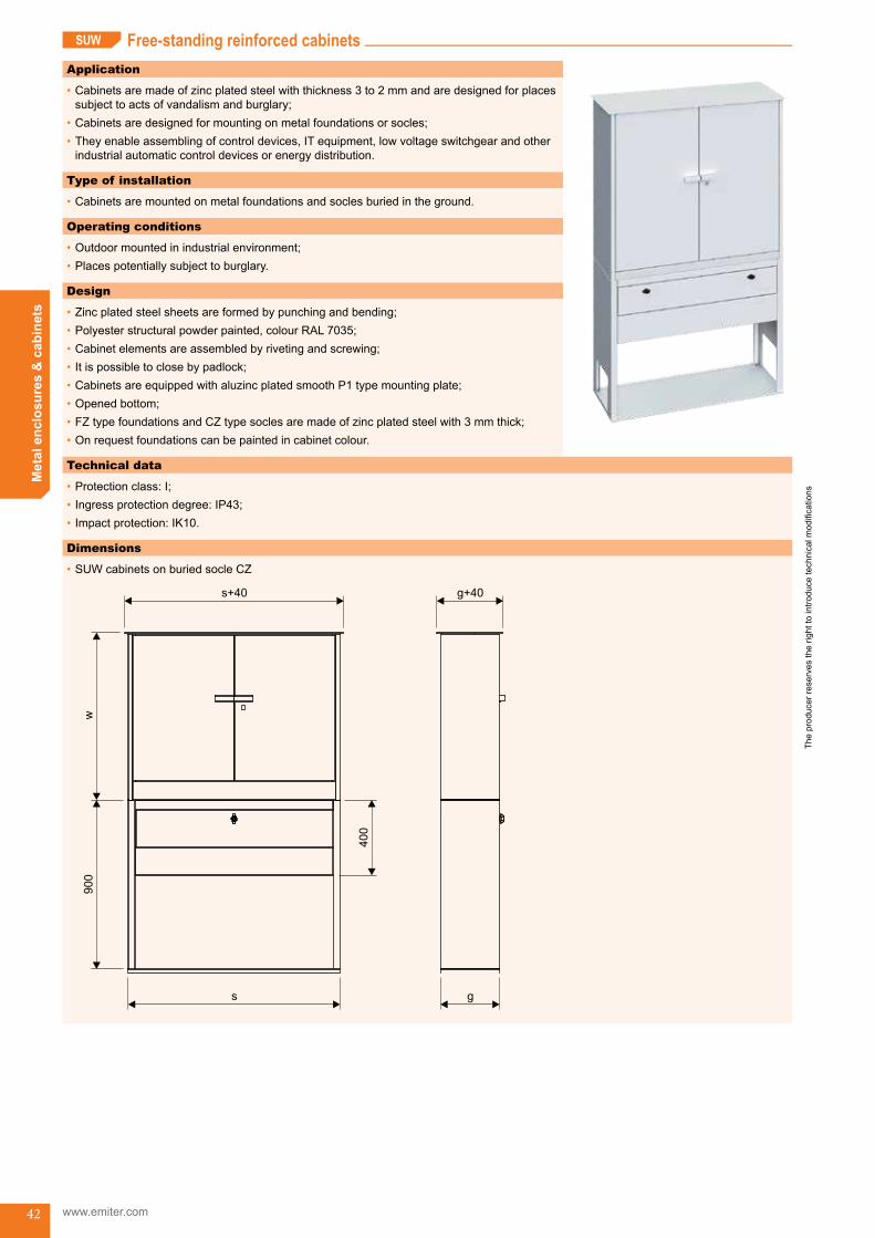
Free-standing reinforced cabinetsSUW
Application
•Cabinetsaremadeofzincplatedsteelwiththickness3to2mmandaredesignedforplacessubjecttoactsofvandalismandburglary;
•Cabinetsaredesignedformountingonmetalfoundationsorsocles;•Theyenableassemblingofcontroldevices,ITequipment,lowvoltageswitchgearandotherindustrialautomaticcontroldevicesorenergydistribution.
Type of installation
•Cabinetsaremountedonmetalfoundationsandsoclesburiedintheground.
Operating conditions
•Outdoormountedinindustrialenvironment;•Placespotentiallysubjecttoburglary.
Design
•Zincplatedsteelsheetsareformedbypunchingandbending;•Polyesterstructuralpowderpainted,colourRAL7035;•Cabinetelementsareassembledbyrivetingandscrewing;•Itispossibletoclosebypadlock;•CabinetsareequippedwithaluzincplatedsmoothP1typemountingplate;•Openedbottom;•FZtypefoundationsandCZtypesoclesaremadeofzincplatedsteelwith3mmthick;•Onrequestfoundationscanbepaintedincabinetcolour.
Technical data
•Protectionclass:I;•Ingressprotectiondegree:IP43;•Impactprotection:IK10.
Dimensions
•SUW cabinets on buried socle CZ
s
s+40
900
w
g
g+40
400
Free-standing reinforced cabinets (SUW) SUW_start

The
prod
ucer
rese
rves
the
right
to in
trodu
ce te
chni
cal m
odifi
catio
ns
Met
al e
nclo
sure
s &
cab
inet
s
43
Scope of delivery
•SUWcabinetwithmountingplate.
SUW
•SUW cabinets on buried foundation FZ
s
s+40900
w
g
g+40
200
Reference chart
cabinet typedimensions [mm] no.of
doorsburied foundation
FZburied socle
CZs w g
SUW 50 90 32 500 900 320 1 FZ 50 32 90 CZ 50 32 90SUW 50 120 34 500 1200 340 1 FZ 50 34 90 CZ 50 34 90SUW 60 90 32 600 900 320 1 FZ 60 32 90 CZ 60 32 90SUW 60 120 34 600 1200 340 1 FZ 60 34 90 CZ 60 34 90SUW 80 90 32 800 900 320 1 FZ 80 32 90 CZ 80 32 90SUW 80 120 34 800 1200 340 1 FZ 80 34 90 CZ 80 34 90SUW 115 90 32 1150 900 320 2 FZ 115 32 90 CZ 115 32 90SUW 115 120 34 1150 1200 340 2 FZ 115 34 90 CZ 115 34 90
How to order
width (s)
height (w)
External dimension number [cm]
depth (g)
Additional requirements description
Free-standing reinforced cabinet
-FZ buried foundation
- buried socleCZ
Foundation/socle
-SUW -
•Orderingexample: - Free-standingreinforcedcabinetwithburiedsocleSUW809032CZ.
SUW_end
The
prod
ucer
rese
rves
the
right
to in
trodu
ce te
chni
cal m
odifi
catio
ns
www.emiter.com
Met
al e
nclo
sure
s &
cab
inet
s
44
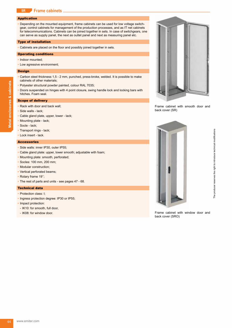
Frame cabinetsSR
Application
•Dependingonthemountedequipment,framecabinetscanbeusedforlowvoltageswitch-gear,controlcabinetsformanagementoftheproductionprocesses,andasITnetcabinetsfortelecommunications.Cabinetscanbejoinedtogetherinsets.Incaseofswitchgears,onecanserveassupplypanel,thenextasoutletpanelandnextasmeasuringpaneletc.
Type of installation
•Cabinetsareplacedonthefloorandpossiblyjoinedtogetherinsets.
Operating conditions
•Indoormounted;•Lowagressiveenvironment;
Design
•Carbonsteelthickness1,5-2mm,punched,press-broke,welded.Itispossibletomakecabinetsofothermaterials;
•Polyesterstructuralpowderpainted,colourRAL7035;•Doorssuspendedonhingeswith4pointclosure,swinghandlelockandlockingbarswithhitches.Foamseal.
Scope of delivery
•Rackwithdoorandbackwall;•Sidewalls-lack;•Cableglandplate,upper,lower-lack;•Mountingplate-lack;•Socle-lack;•Transportrings-lack;•Lockinsert-lack.
Accessories
•Sidewalls:innerIP30,outerIP55;•Cableglandplate:upper,lowersmooth;adjustablewithfoam;•Mountingplate:smooth,perforated;•Socles:100mm,200mm;•Modularconstruction;•Verticalperforatedbeams;•Rotaryframe19’’;•Therestofpartsandunits-seepages47-68.
Technical data
•Protectionclass:I;•Ingressprotectiondegree:IP30orIP55;•Impactprotection:
- IK10:forsmooth,fulldoor, - IK08:forwindowdoor.
Frame cabinet with smooth door andback cover (SR)
Frame cabinet with window door andback cover (SRO)
Frame cabinets (SR) SR_start
The
prod
ucer
rese
rves
the
right
to in
trodu
ce te
chni
cal m
odifi
catio
ns
Met
al e
nclo
sure
s &
cab
inet
s
45
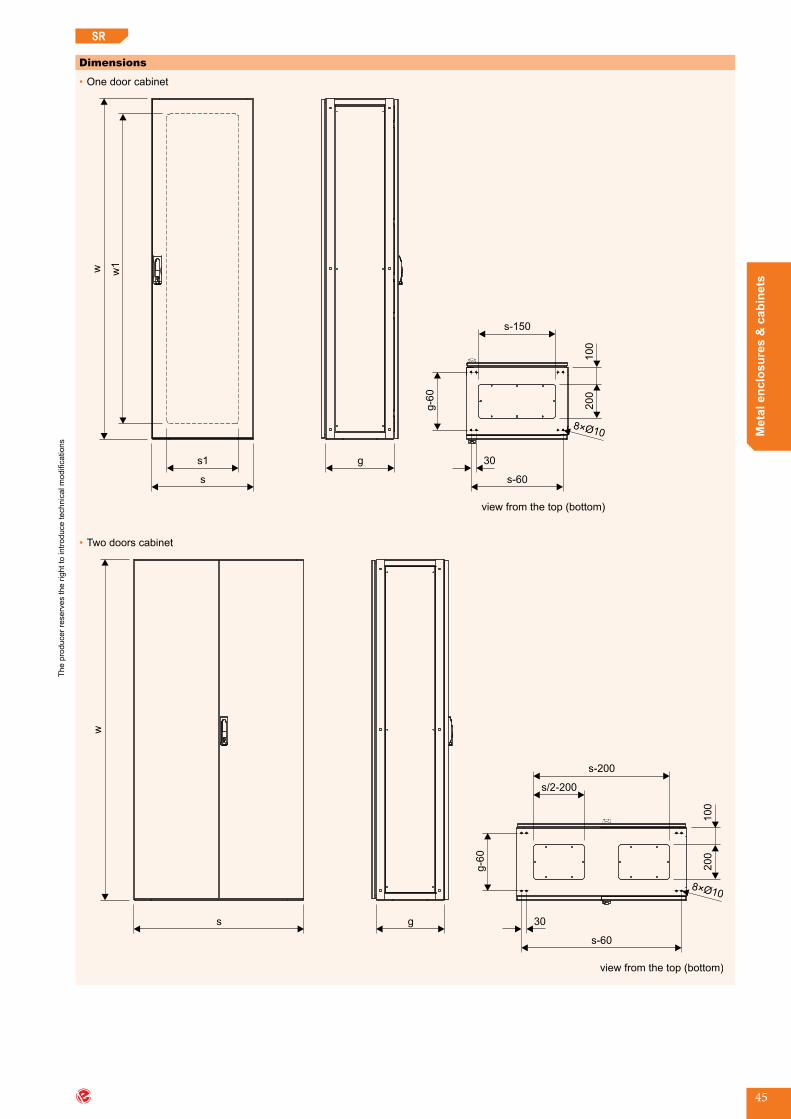
SR
Dimensions
•One door cabinet
g
w1w
s
s1
g-6
0
s-60
30
s-150
200
100
8×Ø10
view from the top (bottom)
•Two doors cabinet
view from the top (bottom)
g
w
s
g-6
0
s-60
30
200
100
8×Ø10
s/2-200
s-200
The
prod
ucer
rese
rves
the
right
to in
trodu
ce te
chni
cal m
odifi
catio
ns
www.emiter.com
Met
al e
nclo
sure
s &
cab
inet
s
46
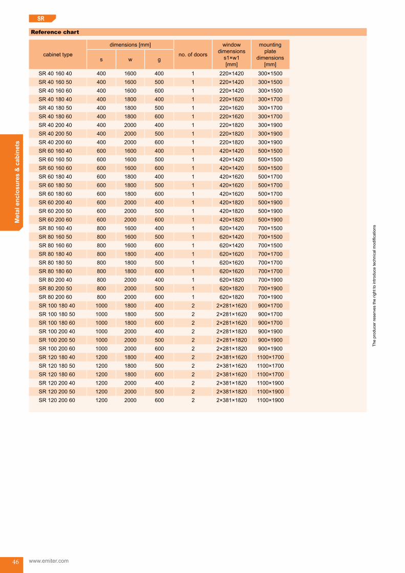
Reference chart
cabinet type
dimensions [mm]
no.ofdoors
window dimensions
s1×w1 [mm]
mounting plate
dimensions[mm]
s w g
SR 40 160 40 400 1600 400 1 220×1420 300×1500SR 40 160 50 400 1600 500 1 220×1420 300×1500SR 40 160 60 400 1600 600 1 220×1420 300×1500SR 40 180 40 400 1800 400 1 220×1620 300×1700SR 40 180 50 400 1800 500 1 220×1620 300×1700SR 40 180 60 400 1800 600 1 220×1620 300×1700SR 40 200 40 400 2000 400 1 220×1820 300×1900SR 40 200 50 400 2000 500 1 220×1820 300×1900SR 40 200 60 400 2000 600 1 220×1820 300×1900SR 60 160 40 600 1600 400 1 420×1420 500×1500SR 60 160 50 600 1600 500 1 420×1420 500×1500SR 60 160 60 600 1600 600 1 420×1420 500×1500SR 60 180 40 600 1800 400 1 420×1620 500×1700SR 60 180 50 600 1800 500 1 420×1620 500×1700SR 60 180 60 600 1800 600 1 420×1620 500×1700SR 60 200 40 600 2000 400 1 420×1820 500×1900SR 60 200 50 600 2000 500 1 420×1820 500×1900SR 60 200 60 600 2000 600 1 420×1820 500×1900SR 80 160 40 800 1600 400 1 620×1420 700×1500SR 80 160 50 800 1600 500 1 620×1420 700×1500SR 80 160 60 800 1600 600 1 620×1420 700×1500SR 80 180 40 800 1800 400 1 620×1620 700×1700SR 80 180 50 800 1800 500 1 620×1620 700×1700SR 80 180 60 800 1800 600 1 620×1620 700×1700SR 80 200 40 800 2000 400 1 620×1820 700×1900SR 80 200 50 800 2000 500 1 620×1820 700×1900SR 80 200 60 800 2000 600 1 620×1820 700×1900SR 100 180 40 1000 1800 400 2 2×281×1620 900×1700SR 100 180 50 1000 1800 500 2 2×281×1620 900×1700SR 100 180 60 1000 1800 600 2 2×281×1620 900×1700SR 100 200 40 1000 2000 400 2 2×281×1820 900×1900SR 100 200 50 1000 2000 500 2 2×281×1820 900×1900SR 100 200 60 1000 2000 600 2 2×281×1820 900×1900SR 120 180 40 1200 1800 400 2 2×381×1620 1100×1700SR 120 180 50 1200 1800 500 2 2×381×1620 1100×1700SR 120 180 60 1200 1800 600 2 2×381×1620 1100×1700SR 120 200 40 1200 2000 400 2 2×381×1820 1100×1900SR 120 200 50 1200 2000 500 2 2×381×1820 1100×1900SR 120 200 60 1200 2000 600 2 2×381×1820 1100×1900
SR

The
prod
ucer
rese
rves
the
right
to in
trodu
ce te
chni
cal m
odifi
catio
ns
Met
al e
nclo
sure
s &
cab
inet
s
47
SR
How to order
SR
Frame cabinet
width (s)
height (w)
External dimension number [cm]
depth (g)
Outer door
no mark - full doors
- door with windowO
-
Additional requirements description
•Orderingofaccessories:specifytypeofaccessoriesandnumberofpieces:•Orderingexample:
- FramecabinetSR10020040.
ACCESSORIES FOR SR CABINETS
Application
•Forclosingthesidesoftheframeorrowofframes.
Variety
•BRW-innertype,fixedbyboltstotheframe.Itismountedtothepocketoftheframe,doesnotincreasewidthoftheframe.Whenframesareconnectedinseriesitservesaspartitionwall.EnsuresIP30.
•BRZ-outertype,fixedbyboltstotheframe.Itismountedoutsideoftheframeandincre-aseswidthoftheframeby25mmperside.EqiuppedwithsealingensuresIP55.
Design
•Madeofsteel,thickness1,5mm;•Paintedwithpowderpaints,colourRAL7035.
Dimensions
•BRW
g
w
A
A
A-A
•BRZ
g
w
A
A
A-A
Side wall - BRW, BRZ
Accessories for SR cabinets
wyp-SR-start

The
prod
ucer
rese
rves
the
right
to in
trodu
ce te
chni
cal m
odifi
catio
ns
www.emiter.com
Met
al e
nclo
sure
s &
cab
inet
s
48
SR
Reference chart
cabinet type
inner side wall BRW outer side wall BRZ
typedimensions
[mm] w×g
typedimensions
[mm] w×g
SR...16040 BRW 160 40 1518×292 BRZ 160 40 1590×390SR...16050 BRW 160 50 1518×392 BRZ 160 50 1590×490SR...16060 BRW 160 60 1518×492 BRZ 160 60 1590×590SR...18040 BRW 180 40 1718×292 BRZ 180 40 1790×390SR...18050 BRW 180 50 1718×392 BRZ 180 50 1790×490SR...18060 BRW 180 60 1718×492 BRZ 180 60 1790×590SR...20040 BRW 200 40 1918×292 BRZ 200 40 1990×390SR...20050 BRW 200 50 1918×392 BRZ 200 50 1990×490SR...20060 BRW 200 60 1918×492 BRZ 200 60 1990×590
How to order
•InnersidewallBRW16080(forSRXX18080);•OutersidewallBRZ18060(forSRXX18060).
Application
•SRcabinetshaveupperandloweropenings,whichtoproviderequiredIPdegreemustbecoveredusingcableglandplates.
Variety
•K:smoothcableglandplate;•KG:adjustablecableglandplatewithfoamsealing.
Design
•Itismadeofaluzincplatedsteel,thickness1,5mm,withsealing.MovableC-profilesareequippedwithfoams;
•Ingressprotection:-K:IP55,-KG:IP20.
Cable gland plates are equippded with bolt kit.
Side walls are delivered with bolt kit.
Cable gland plate (upper, lower) - K, KG
Dimensions
•Smoothcableglandplate-K
5
g =
280
160
270
s
60
•Adjustablecableglandplatewithfoamsealing-KG
t
s1
s
125
g =
280
t = 5min
t = 105max

The
prod
ucer
rese
rves
the
right
to in
trodu
ce te
chni
cal m
odifi
catio
ns
Met
al e
nclo
sure
s &
cab
inet
s
49
SR
Reference chart
cabinet typeK cable gland plate KG cable gland plate
type dimensions s×g [mm] type dimensions
s×g [mm]usefulwidth
s1 [mm]
SR40...40 K 40 250×280 KG 40 250×280 180SR40...50 K 40 250×280 KG 40 250×280 180SR40...60 K 40 250×280 KG 40 250×280 180SR60...40 K 60 450×280 KG 60 450×280 380SR60...50 K 60 450×280 KG 60 450×280 380SR60...60 K 60 450×280 KG 60 450×280 380SR80...40 K 80 650×280 KG 80 650×280 580SR80...50 K 80 650×280 KG 80 650×280 580SR80...60 K 80 650×280 KG 80 650×280 580SR100...40 K 100 2× 350×280 KG 100 2× 350×280 2× 280SR100...50 K 100 2× 350×280 KG 100 2× 350×280 2× 280SR100...60 K 100 2× 350×280 KG 100 2× 350×280 2× 280SR120...40 K 120 2× 450×280 KG 120 2× 450×280 3× 380SR120...50 K 120 2× 450×280 KG 120 2× 450×280 3× 380SR120...60 K 120 2× 450×280 KG 120 2× 450×280 3× 380
Dimensions
•PR1
s-100
w-1
00
12
25
23
•PR2
Ø5,2
25
25
How to order
•Smoothcableglandplate-K80;•Adjustablecableglandplatewithfoamsealing-KG100.
Mounting plates - PR1, PR2Application
•Formountingelectricalandelectronicapparatus.
Variety
•PR1:smoothmountingplate;•PR2:mountingplate,holesØ5,2(underthreadM6)spacing25x25mm.
Design
•PR1,PR2aremadeofaluzincplatedsteel,thickness2,0mm.Mountingplatesaremountedintocabinetsusingbrackets.
The
prod
ucer
rese
rves
the
right
to in
trodu
ce te
chni
cal m
odifi
catio
ns
www.emiter.com
Met
al e
nclo
sure
s &
cab
inet
s
50
SR
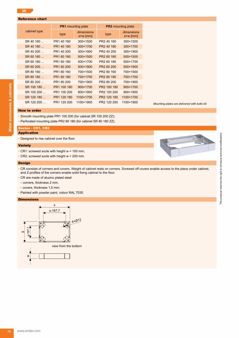
Application
•Designedtorisecabinetoverthefloor.
Variety
•CR1:screwedsoclewithheightw=100mm;•CR2:screwedsoclewithheightw=200mm.
Reference chart
cabinet typePR1 mounting plate PR2 mounting plate
type dimensions s×w [mm] type dimensions
s×w [mm]
SR40160... PR1 40 160 300×1500 PR2 40 160 300×1500SR40180... PR1 40 180 300×1700 PR2 40 180 300×1700SR40200... PR1 40 200 300×1900 PR2 40 200 300×1900SR60160... PR1 60 160 500×1500 PR2 60 160 500×1500SR60180... PR1 60 180 500×1700 PR2 60 180 500×1700SR60200... PR1 60 200 500×1900 PR2 60 200 500×1900SR80160... PR1 80 160 700×1500 PR2 80 160 700×1500SR80180... PR1 80 180 700×1700 PR2 80 180 700×1700SR80200... PR1 80 200 700×1900 PR2 80 200 700×1900SR100180... PR1 100 180 900×1700 PR2 100 180 900×1700SR100200... PR1 100 200 900×1900 PR2 100 200 900×1900SR120180... PR1 120 180 1100×1700 PR2 120 180 1100×1700SR120200... PR1 120 200 1100×1900 PR2 120 200 1100×1900
How to order
•SmoothmountingplatePR1100200(forcabinetSR100200ZZ);•PerforatedmountingplatePR280180(forcabinetSR80180ZZ).
Mounting plates are delivered with bolts kit.
Socles - CR1, CR2
Design
•CRconsistsofcornersandcovers.Weightofcabinetrestsoncorners.Screwedoffcoversenableaccesstotheplaceundercabinet,andZ-profilesofthecornersenablesolidfixingcabinettothefloor.
•CRaremadeofaluzincplatedsteel: - corners,thickness2mm, - covers,thickness1,5mm;
•Paintedwithpowderpaint,colourRAL7035.
Dimensions
g-1
67,7
g
s-167,7
s
4×Ø12
w
view from the bottom

The
prod
ucer
rese
rves
the
right
to in
trodu
ce te
chni
cal m
odifi
catio
ns
Met
al e
nclo
sure
s &
cab
inet
s
51
SR
Reference chart
cabinet type
CR1 socle(w=100mm)
CR2 socle(w=200mm)
type dimensionss×g [mm] type dimensions
s×g [mm]
SR40...40 CR1 40 40 400×400 CR2 40 40 400×400SR40...50 CR1 40 50 400×500 CR2 40 50 400×500SR40...60 CR1 40 60 400×600 CR2 40 60 400×600SR60...40 CR1 60 40 600×400 CR2 60 40 600×400SR60...50 CR1 60 50 600×500 CR2 60 50 600×500SR60...60 CR1 60 60 600×600 CR2 60 60 600×600SR80...40 CR1 80 40 800×400 CR2 80 40 800×400SR80...50 CR1 80 50 800×500 CR2 80 50 800×500SR80...60 CR1 80 60 800×600 CR2 80 60 800×600SR100...40 CR1 100 40 1000×400 CR2 100 40 1000×400SR100...50 CR1 100 50 1000×500 CR2 100 50 1000×500SR100...60 CR1 100 40 1000×600 CR2 100 40 1000×600SR120...40 CR1 120 40 1200×400 CR2 120 40 1200×400SR120...50 CR1 120 50 1200×500 CR2 120 50 1200×500SR120...60 CR1 120 60 1200×600 CR2 120 60 1200×600
How to order
•Socle100mmCR110040(forSR100YYY40);•Socle200mmCR210050(forSR100YYY50).
Socles are delivered with bolts kit.

The
prod
ucer
rese
rves
the
right
to in
trodu
ce te
chni
cal m
odifi
catio
ns
www.emiter.com
Met
al e
nclo
sure
s &
cab
inet
s
52
SR
Swing frame 19’’ - RUR19Application
•Itservestomount19’’devicesintheSRcabinetswith800mmwidth.
Variety
•RUR19 S:swingframe19’’,symmetrical;•RUR19 N:swingframe19’’,asymmetrical.
Design
•Frameismadeofsteelprofileswiththickness2mm,welded.Equippedwithhingeswithpossibilitytochangeopening-left,right-direc-tion.M22typelockclosurewithroundbars.
•Maximumload-160kg;•Maximumdepthofthedevices:
- symmetrical - 360 mm, - asymmetrical-440mm;
•Paintedwithpowderpaint,colourRAL7035.
Dimensions
•RUR19 SA B
C
750
725
655
515
450
465
70 70
•RUR19 N
140
655
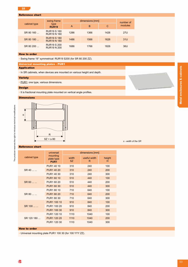
The
prod
ucer
rese
rves
the
right
to in
trodu
ce te
chni
cal m
odifi
catio
ns
Met
al e
nclo
sure
s &
cab
inet
s
53
Reference chart
cabinet typeswing frame
type RUR19
dimensions [mm] number of modulesA B C
SR80160... RUR19 S 160RUR19 N 160 1286 1366 1426 27U
SR80180... RUR19 S 180RUR19 N 180 1486 1566 1626 31U
SR80200... RUR19 S 200RUR19 N 200 1686 1766 1826 36U
How to order
•Swingframe19’’symmetrical:RUR19S200(forSR80200ZZ).
SR
Application
•InSRcabinets,whendevicesaremountedonvariousheightanddepth.
Variety
•PUR1:onetype,variousdimensions.
Design
•Itisfractionalmountingplatemountedonverticalangleprofiles.
Universal mounting plates - PUR1
Dimensions
R
SZ = s-90
H
Reference chart
cabinet type
universal mounting plate type
PUR1
dimensions [mm]
widthSZ
usefulwidthR
heightH
SR40......PUR1 40 10 310 240 100PUR1 40 20 310 240 200PUR1 40 30 310 240 300
SR60......PUR1 60 10 510 440 100PUR1 60 20 510 440 200PUR1 60 30 510 440 300
SR80......PUR1 80 10 710 640 100PUR1 80 20 710 640 200PUR1 80 30 710 640 300
SR100......PUR1 100 10 910 840 100PUR1 100 20 910 840 200PUR1 100 30 910 840 300
SR120180...PUR1 120 10 1110 1040 100PUR1 120 20 1110 1040 200PUR1 120 30 1110 1040 300
How to order
•UniversalmountingplatePUR110030(for100YYYZZ).
s - width of the SR

The
prod
ucer
rese
rves
the
right
to in
trodu
ce te
chni
cal m
odifi
catio
ns
www.emiter.com
Met
al e
nclo
sure
s &
cab
inet
s
54
SR
Application
•Formountingofmountingplates,bracketsonvariousheightsanddepths.
Design
•Anglebarhastheperforationwithsquare10×10mmholeswithraster25mm.ElementsaremountedusingcagenutsM6andscrewswithwashers.Itismadeofaluzincplatedsteel,thickness2mm.
Dimensions
w-5
0
25
40
10 10×
Application
•Formountingofverticalprofile19”inSRcabinet,width800mm.
Design
•Itismadeofaluzincplatedsteel,thickness2mm.
How to order
•Bracketofverticalprofile19’’-WPR(4pieces)*
* It is delivered with mounting kit.
Application
•Formounting19’’devicesonvariousheightsanddepths.
Design
•Perforatedprofilewithholes10×10mm,spacingUpattern.•DevicesaremountedusingcagenutsM6andscrewswithwashers.•Itismadeofaluzincplatedsteel,thickness2mm.
w - height of SR
Vertical angle bar (left, right) metric - KPR
Reference chart
cabinet type angle bar type KPR
angle bar length
(w-50) [mm]
SR...160... KPR 160 1550SR...180... KPR 180 1750SR...200... KPR 200 1950
How to order
•Thepairofverticalanglebars,metricKPR180(forSRcabinetswithheight1800mm).
It is delivered the pair of angle bars with mounting kit.
Vertical profile 19’’ - PR19
Bracket of vertical profile 19” (PR19) - WPR
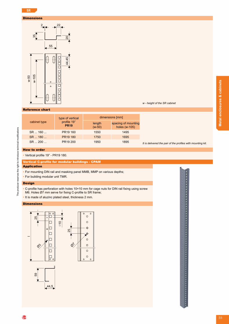
The
prod
ucer
rese
rves
the
right
to in
trodu
ce te
chni
cal m
odifi
catio
ns
Met
al e
nclo
sure
s &
cab
inet
s
55
SR
Application
•FormountingDINrailandmaskingpanelMMB,MMPonvariousdepths;•ForbuildingmodularunitTMR.
Design
•C-profilehasperforationwithholes10×10mmforcagenutsforDINrailfixingusingscrewM6.HolesØ7mmserveforfixingC-profiletoSRframe;
•Itismadeofaluzincplatedsteel,thickness2mm.
Dimensions
35
55
20
222w
-50
w-1
05
44,4
5
Reference chart
cabinet typetype of vertical profile19’’
PR19
dimensions [mm]
length(w-50)
spacing of mounting holes(w-105)
SR...160... PR19 160 1550 1495SR...180... PR19 180 1750 1695SR...200... PR19 200 1950 1895
How to order
•Verticalprofile19”-PR19180.
Dimensions
44,5
59
25
□10
25
l
It is delivered the pair of the profiles with mounting kit.
w - height of the SR cabinet
SR
Vertical C-profile for modular buildings - CPAM
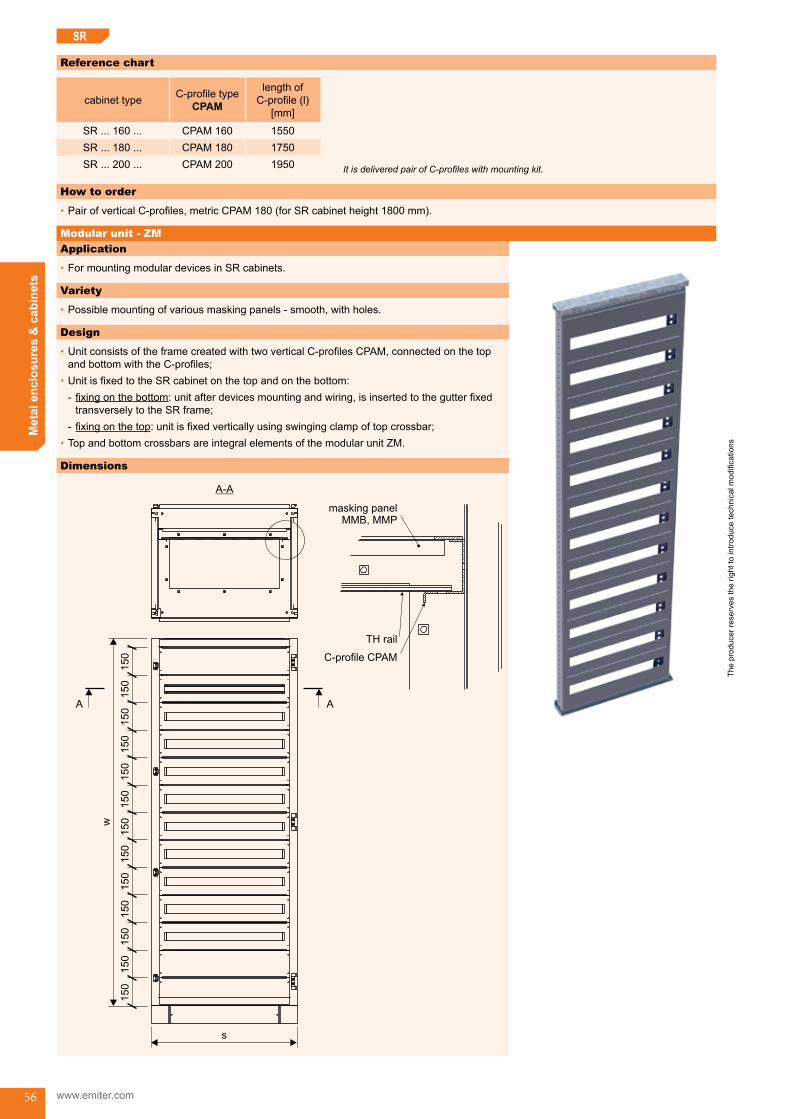
The
prod
ucer
rese
rves
the
right
to in
trodu
ce te
chni
cal m
odifi
catio
ns
www.emiter.com
Met
al e
nclo
sure
s &
cab
inet
s
56
SR
Reference chart
cabinet type C-profiletypeCPAM
lengthofC-profile (l)
[mm]
SR...160... CPAM 160 1550SR...180... CPAM 180 1750SR...200... CPAM 200 1950
How to order
•PairofverticalC-profiles,metricCPAM180(forSRcabinetheight1800mm).
It is delivered pair of C-profiles with mounting kit.
Application
•FormountingmodulardevicesinSRcabinets.
Variety
•Possiblemountingofvariousmaskingpanels-smooth,withholes.
Design
•UnitconsistsoftheframecreatedwithtwoverticalC-profilesCPAM,connectedonthetopandbottomwiththeC-profiles;
•UnitisfixedtotheSRcabinetonthetopandonthebottom: - fixingonthebottom:unitafterdevicesmountingandwiring,isinsertedtothegutterfixedtransverselytotheSRframe;
- fixingonthetop:unitisfixedverticallyusingswingingclampoftopcrossbar;•TopandbottomcrossbarsareintegralelementsofthemodularunitZM.
Dimensions
s
150
150
150
150
150
150
150
150
150
150
150
150
150
w
A A
A-A
C-profile CPAM
TH rail
masking panelMMB, MMP
Modular unit - ZM

The
prod
ucer
rese
rves
the
right
to in
trodu
ce te
chni
cal m
odifi
catio
ns
Met
al e
nclo
sure
s &
cab
inet
s
57
SR
Reference chart
cabinet type modular unit ZM type
no.ofmodulesin masking
panel
no.ofmaskingpanel in
modular unit
sum of modules in
modular unit
external dimension s×w [mm]
SR40160... ZM 40 160 15 10 150 322×1500SR40180... ZM 40 180 15 11 165 322×1650SR40200... ZM 40 200 15 13 195 322×1950SR60160... ZM 60 160 26 10 260 522×1500SR60180... ZM 60 180 26 11 286 522×1650SR60200... ZM 60 200 26 13 338 522×1950SR80160... ZM 80 160 38 10 380 722×1500SR80180... ZM 80 180 38 11 418 722×1650SR80200... ZM 80 200 38 13 494 722×1950SR100180... ZM 100 180 49 11 539 922×1650SR100200... ZM 100 200 49 13 637 922×1950SR120180... ZM 120 180 61 11 671 1122×1650SR120200... ZM 120 200 61 13 793 1122×1950
How to order
•ModularunitZM80200(forcabinetSR80200ZZ).
Modular unit is delivered as mounted.
Application
•FormountingofmodulardevicesinSRcabinets.
Variety
•TMR:oneconstructiontype,thenumberofmaskingpanelsdependsonthesizeofthecabinet.
Design
•UnitconsistsoftwoverticalC-profilesCPAM,maskingpanels,DINrails.Unitisunderstood assetofpartsforTMRbuilding,notasoneseparateelement.ItismountedtothesidebracketsoftheSRframe.
Modular unit - TMR
Reference chart
cabinet type modular unit TMR type
no.ofmodulesin masking
panel
no.ofmaskingpanelsinthemodular unit
sumofthemodulesinthemodular unit
external dimension s×w [mm]
SR40160... TMR 40 160 15 10 150 320×1500SR40180... TMR 40 180 15 11 165 320×1650SR40200... TMR 40 200 15 13 195 320×1950SR60160... TMR 60 160 26 10 260 520×1500SR60180... TMR 60 180 26 11 286 520×1650SR60200... TMR 60 200 26 13 338 520×1950SR80160... TMR 80 160 38 10 380 720×1500SR80180... TMR 80 180 38 11 418 720×1650SR80200... TMR 80 200 38 13 494 720×1950SR100180... TMR 100 180 49 11 539 920×1650SR100200... TMR 100 200 49 13 637 920×1950SR120180... TMR 120 180 61 11 671 1120×1650SR120200... TMR 120 200 61 13 793 1120×1950
How to order
•ModularunitTMR80200(forcabinetSR80200ZZ).
One construction type, the num-ber of masking panels depends on the size of the cabinet.
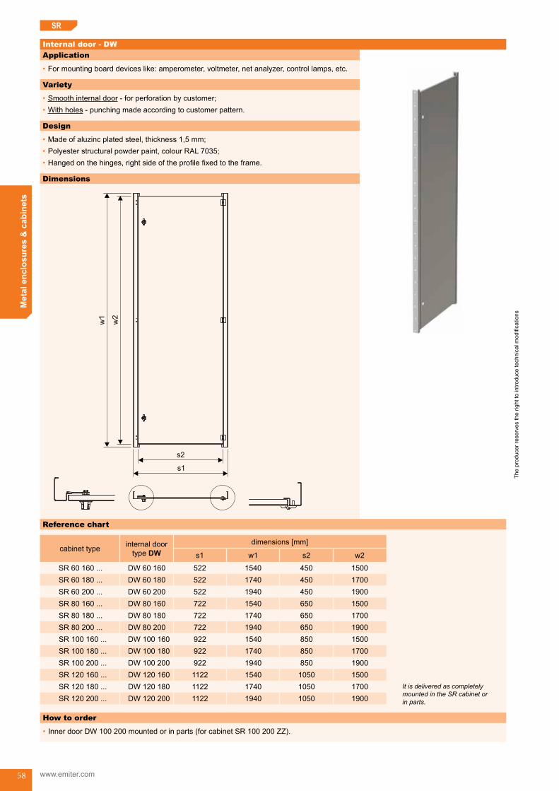
The
prod
ucer
rese
rves
the
right
to in
trodu
ce te
chni
cal m
odifi
catio
ns
www.emiter.com
Met
al e
nclo
sure
s &
cab
inet
s
58
Application
•Formountingboarddeviceslike:amperometer,voltmeter,netanalyzer,controllamps,etc.
Variety
•Smoothinternaldoor-forperforationbycustomer;•Withholes-punchingmadeaccordingtocustomerpattern.
Design
•Madeofaluzincplatedsteel,thickness1,5mm;•Polyesterstructuralpowderpaint,colourRAL7035;•Hangedonthehinges,rightsideoftheprofilefixedtotheframe.
Dimensions
s2
s1
w2
w1
SR
Internal door - DW
Reference chart
cabinet type internal door type DW
dimensions [mm]
s1 w1 s2 w2
SR60160... DW 60 160 522 1540 450 1500SR60180... DW 60 180 522 1740 450 1700SR60200... DW 60 200 522 1940 450 1900SR80160... DW 80 160 722 1540 650 1500SR80180... DW 80 180 722 1740 650 1700SR80200... DW 80 200 722 1940 650 1900SR100160... DW 100 160 922 1540 850 1500SR100180... DW 100 180 922 1740 850 1700SR100200... DW 100 200 922 1940 850 1900SR120160... DW 120 160 1122 1540 1050 1500SR120180... DW 120 180 1122 1740 1050 1700SR120200... DW 120 200 1122 1940 1050 1900
How to order
•InnerdoorDW100200mountedorinparts(forcabinetSR100200ZZ).
It is delivered as completely mounted in the SR cabinet or in parts.

The
prod
ucer
rese
rves
the
right
to in
trodu
ce te
chni
cal m
odifi
catio
ns
Met
al e
nclo
sure
s &
cab
inet
s
59
Reference chart
typedimensions [mm] maximalno.
of modulescabinetwidth l w d g c
MMB 40
400 314
150 1001 8
14
MMP 40 3 15MMB 40
200 1501 8
MMP 40 3 15MMB 40
250 2001 8
MMP 40 3 15MMB 60
600 514
150 4001 8
25
MMP 60 3 15MMB 60
200 5001 8
MMP 60 3 15MMB 60
250 6001 8
MMP 60 3 15MMB 80
800 714
150 1001 8
36
MMP 60 3 15MMB 60
200 1501 8
MMP 60 3 15MMB 60
250 2001 8
MMP 60 3 15MMB 100
1000 914
150 1001 8
47
MMP 100 3 15MMB 100
200 1501 8
MMP 100 3 15MMB 100
250 2001 8
MMP 100 3 15MMB 120
1200 1114
150 1001 8
58
MMP 120 3 15MMB 120
200 1501 8
MMP 120 3 15MMB 120
250 2501 8
MMP 120 3 15
lx=18n;x=18,n-numberofmodules
SR
Application
•ForcoveringmodulardevicesfixedtotheDINrailinSR,OWWcabinets.
Type of installation
•Maskingpanelsaremountedtothesideprofilesusingself-tappingscrews.
Design
•MaskingpanelsMMBaremadeofaluzincplatedsteel;•MaskingpanelsMMParemadeofPVCsheet;•Holesunderdevicesaremadeformaximumwidth.
Masking panels of modular devices - MMB, MMP
Dimensions
20
30 lx
l
w d
c
g
47
9
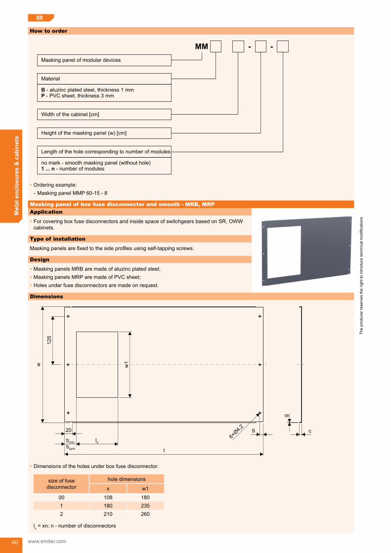
The
prod
ucer
rese
rves
the
right
to in
trodu
ce te
chni
cal m
odifi
catio
ns
www.emiter.com
Met
al e
nclo
sure
s &
cab
inet
s
60
How to order
MM
Masking panel of modular devices
Width of the cabinet [cm]
Length of the hole corresponding to number of modules
Material
B
P
- aluzinc plated steel, thickness 1 mm- PVC sheet, thickness 3 mm
no mark - smooth masking panel (without hole)- number of modules1 ... n
Height of the masking panel (w) [cm]
•Orderingexample: - Masking panel MMP 60-15 - 8
Application
•ForcoveringboxfusedisconnectorsandinsidespaceofswitchgearsbasedonSR,OWWcabinets.
Type of installation
Maskingpanelsarefixedtothesideprofilesusingself-tappingscrews.
Design
•MaskingpanelsMRBaremadeofaluzincplatedsteel;•MaskingpanelsMRParemadeofPVCsheet;•Holesunderfusedisconnectorsaremadeonrequest.
SR
Masking panel of box fuse disconnector and smooth - MRB, MRP
Dimensions
20
bmin lx
lbsym
w
125
w1
c
g
9
•Dimensionsoftheholesunderboxfusedisconnector:
size of fuse disconnector
holedimensions
x w1
00 108 1801 180 2352 210 260
lx=xn;n-numberofdisconnectors
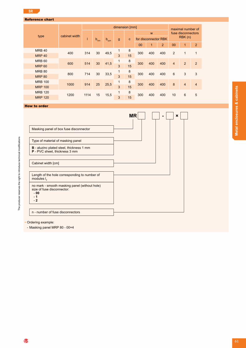
The
prod
ucer
rese
rves
the
right
to in
trodu
ce te
chni
cal m
odifi
catio
ns
Met
al e
nclo
sure
s &
cab
inet
s
61
How to order
MR
Masking panel of box fuse disconnector
Cabinet width [cm]
Length of the hole corresponding to number ofmodules lx
-
Type of material of masking panel
B
P
- aluzinc plated steel, thickness 1 mm- PVC sheet, thickness 3 mm
no mark - smooth masking panel (without hole)size of fuse disconnector:---
00
1
2
n - number of fuse disconnectors
×
•Orderingexample: - Masking panel MRP 80 - 00×4
SR
Reference chart
type cabinetwidth
dimension [mm] maximal number of fuse disconnectors
RBK (n)l bmin bsym g c
w
for disconnector RBK
00 1 2 00 1 2
MRB 40400 314 30 49,5
1 8300 400 400 2 1 1
MRP 40 3 15MRB 60
600 514 30 41,51 8
300 400 400 4 2 2MRP 60 3 15MRB 80
800 714 30 33,51 8
300 400 400 6 3 3MRP 80 3 15MRB 100
1000 914 25 25,51 8
300 400 400 8 4 4MRP 100 3 15MRB 120
1200 1114 15 15,51 8
300 400 400 10 6 5MRP 120 3 15

The
prod
ucer
rese
rves
the
right
to in
trodu
ce te
chni
cal m
odifi
catio
ns
www.emiter.com
Met
al e
nclo
sure
s &
cab
inet
s
62
SR
5
2
3
4
6
1
7
1 - Side cross-bar (WBPR)2 - Vertical side-bar (WBPiR)3 - Internal bar (WWR)4 - Cable cross-bar (WPKR)5 - Angle plate (KR)6-Cableholder(TKR)7-Bracketofcableholder(KTKR)
ACCESSORIES FOR SR CABINET - BRACKET SYSTEM
Accessories for SR cabinet - bracket system
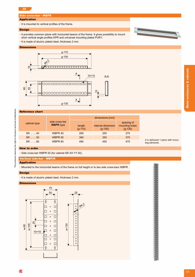
The
prod
ucer
rese
rves
the
right
to in
trodu
ce te
chni
cal m
odifi
catio
ns
Met
al e
nclo
sure
s &
cab
inet
s
63
SR
Application
•Itismountedtoverticalprofilesoftheframe.
Design
•Itprovidescommonplanewithhorizontalbeamsoftheframe.ItgivespossibilitytomountshortverticalangleprofilesKPRanduniversalmountingplatesPUR1;
•Itismadeofaluzincplatedsteel,thickness2mm.
Application
•Mountedtothehorizontalbeamsoftheframeonfullheightortotwosidecross-barsWBPR.
Design
•Itismadeofaluzincplatedsteel,thickness2mm.
Dimensions
w-8
0
w-1
05
75
50
w-1
30
25
25
10 10×
Side cross-bar - WBPR
Dimensions
A
A
16
g-110
g-150
80
50
g-130
10
A-A10×10
Reference chart
cabinet type side cross-bar WBPR type
dimensions [mm]
length(g-110)
internal dimension(g-150)
spacing of mountingholes
(g-130)
SR......40 WBPR 40 290 250 270SR......50 WBPR 50 390 350 370SR......60 WBPR 60 490 450 470
How to order
•Sidecross-barWBPR50(forcabinetSRXXYY50).
It is delivered 1 piece with moun-ting elements.
Vertical side-bar - WBPiR

The
prod
ucer
rese
rves
the
right
to in
trodu
ce te
chni
cal m
odifi
catio
ns
www.emiter.com
Met
al e
nclo
sure
s &
cab
inet
s
64
SR
Reference chart
cabinet type vertical side-bar WBPiR type
dimensions [mm]
length(w-80)
internal dimension(w-130)
spacing of mountingholes
(w-105)
SR...160... WBPiR 160 1520 1470 1495SR...180... WBPiR 180 1720 1670 1695SR...200... WBPiR 200 1920 1870 1895
How to order
•Verticalside-barWBPiR180(forcabinetSRXX180ZZ).
It is delivered 1 piece with fixing elements.
Application
•ItismountedtoverticalsidebarsWBPiR.Itisfittedtothewidthofthecabinet.
Design
•Itismadeofaluzincplatedsteel,thickness2mm.
Application
•Forfixingcablebundles.MountedtotheverticalprofilesoftheSRframeortothedoorreinforcement.
Design
•Itismadeofaluzincplatedsteel,thickness2mm.
Dostawa: 1 sztuka wraz z elementami mocującymi.
Internal bar - WWR
Dimensions
25
12,5
25
25
s-84
75 50
10 10× 12,5
50
15×7
Reference chart
cabinet type internal bar WWR type length(s-84)[mm]
SR40...... WWR 40 316SR60...... WWR 60 516SR80...... WWR 80 716SR100...... WWR 100 916SR120...... WWR 120 1116
How to order
•InternalbarWWR80(forcabinetSR80YYYZZZ).
Cable cross-bar - WPKR
Dimensions
20
10 50
g-160
g-110
1525

The
prod
ucer
rese
rves
the
right
to in
trodu
ce te
chni
cal m
odifi
catio
ns
Met
al e
nclo
sure
s &
cab
inet
s
65
SR
Reference chart
cabinet type cable cross-bar WPKR type
dimensions [mm]
length(g-110)
internal dimension(g-150)
SR......40 WPKR 40 290 240SR......50 WPKR 50 390 340SR......60 WPKR 60 490 440
How to order
•Cablecross-barWPKR50(forcabinetSRXXYYY50).
Angle plate - KRApplication
•Forfixinginternalbars.
Design
•Itismadeofaluzincplatedsteel,thickness2mm.
Application
•Itisappliedinordertoreachuniformplaneoftwomountingplatesincabinetsconnectedinseries.
Design
•Itismadeofaluzincplatedsteel,thickness2mm.
Dimensions
98
w-9
0
Dimensions
75 2
5
45
45
1 72×
10
How to order
•AngleplateKR(forSRcabinet).
It is delivered 1 piece with fixing elements.
It is delivered 1 piece with fixing elements.
Connector of mounting plates - LPR

The
prod
ucer
rese
rves
the
right
to in
trodu
ce te
chni
cal m
odifi
catio
ns
www.emiter.com
Met
al e
nclo
sure
s &
cab
inet
s
66
SR
Reference chart
cabinet typeconnector of
mounting plate LPR type
length(w-90)[mm]
SR...160... LPR 160 1510SR...180... LPR 180 1710SR...200... LPR 200 1910
How to order
•Connectorofmountingplates-LPR180(forcabinetSRXX180ZZ).
It is delivered 1 piece with fixing elements.
Application
•Forfixingincomingandoutgoingcablestothecabinetfromthebottom.Itismountedtotheperforatedprofilesofthecabinetorsoclewithheight200mmusingbracketofcableholder.
Design
•Itismadeofaluzincplatedsteel,thickness2mm.
Application
•Itprovidestofixcableholderinthesoclewithheight200mm.Itismountedtothesidecoverofthesocle.
Design
•Itismadeofaluzincplatedsteel,thickness2mm.
25
g-190
10 10×
63
g-224
25
Cable holder - TKR
Bracket of cable holder - KTKR
Dimensions
40
40
s-130
s-100
s-180
Reference chart
cabinet type cableholderTKR type
dimensions [mm]
length(s-100)
mountingholesspacing (s-130)
SR40...... TKR 40 300 270SR60...... TKR 60 500 470SR80...... TKR 80 700 670SR100...... TKR 100 900 870SR120...... TKR 120 1100 1070
How to order
•CableholderTKR80(forcabinetSR80YYYZZ).
It is delivered 1 piece with mounting elements.
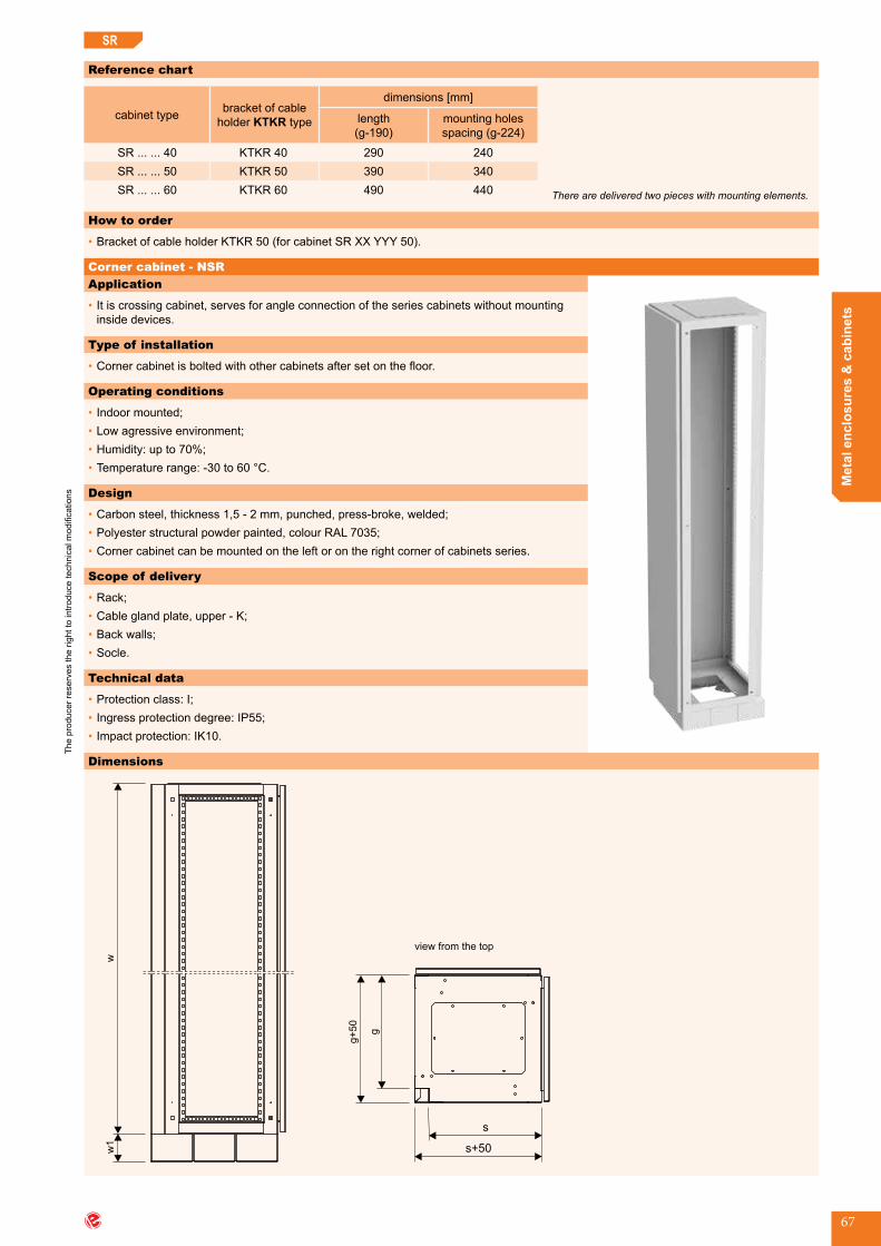
The
prod
ucer
rese
rves
the
right
to in
trodu
ce te
chni
cal m
odifi
catio
ns
Met
al e
nclo
sure
s &
cab
inet
s
67
SR
Reference chart
cabinet type bracket of cable holderKTKR type
dimensions [mm]
length(g-190)
mountingholesspacing (g-224)
SR......40 KTKR 40 290 240SR......50 KTKR 50 390 340SR......60 KTKR 60 490 440
How to order
•BracketofcableholderKTKR50(forcabinetSRXXYYY50).
There are delivered two pieces with mounting elements.
Application
•Itiscrossingcabinet,servesforangleconnectionoftheseriescabinetswithoutmountinginsidedevices.
Type of installation
•Cornercabinetisboltedwithothercabinetsaftersetonthefloor.
Operating conditions
•Indoormounted;•Lowagressiveenvironment;•Humidity:upto70%;•Temperaturerange:-30to60°C.
Design
•Carbonsteel,thickness1,5-2mm,punched,press-broke,welded;•Polyesterstructuralpowderpainted,colourRAL7035;•Cornercabinetcanbemountedontheleftorontherightcornerofcabinetsseries.
Scope of delivery
•Rack;•Cableglandplate,upper-K;•Backwalls;•Socle.
Technical data
•Protectionclass:I;•Ingressprotectiondegree:IP55;•Impactprotection:IK10.
Corner cabinet - NSR
Dimensions
s
s+50
g
g+
50
view from the top
w1
w
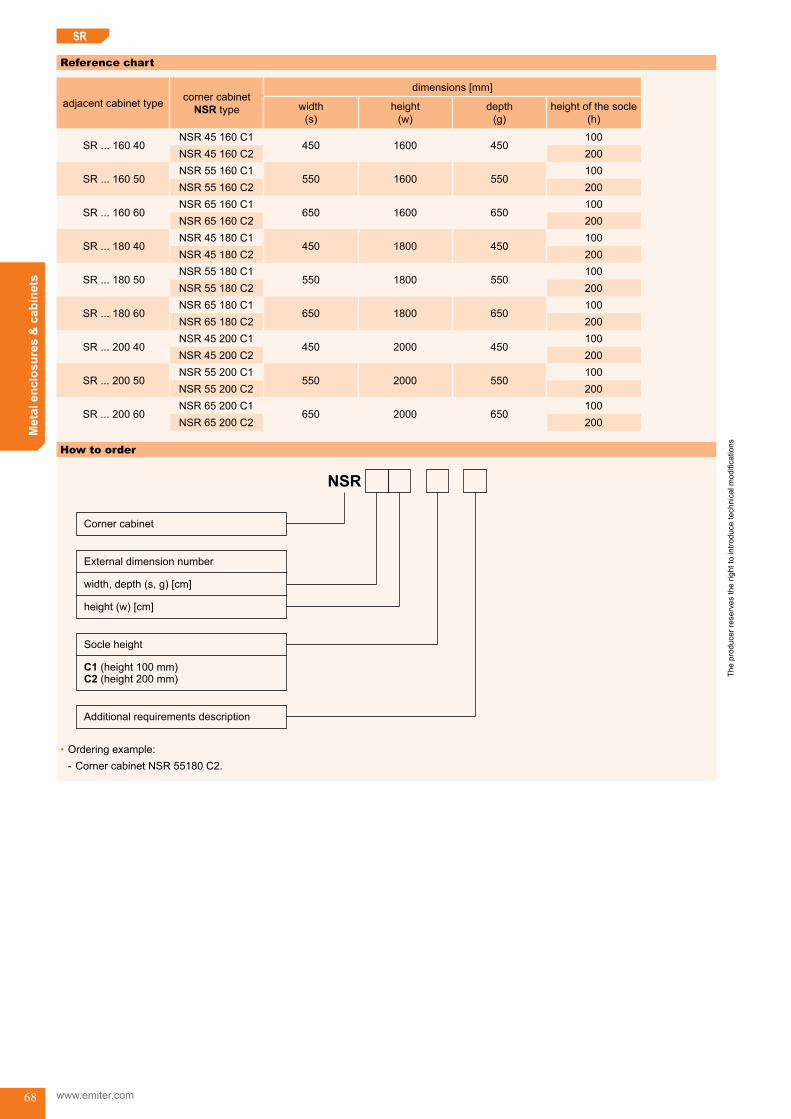
The
prod
ucer
rese
rves
the
right
to in
trodu
ce te
chni
cal m
odifi
catio
ns
www.emiter.com
Met
al e
nclo
sure
s &
cab
inet
s
68
SR
Reference chart
adjacent cabinet type corner cabinet NSR type
dimensions [mm]
width(s)
height(w)
depth(g)
heightofthesocle(h)
SR...16040NSR 45 160 C1
450 1600 450100
NSR 45 160 C2 200
SR...16050NSR 55 160 C1
550 1600 550100
NSR 55 160 C2 200
SR...16060NSR 65 160 C1
650 1600 650100
NSR 65 160 C2 200
SR...18040NSR 45 180 C1
450 1800 450100
NSR 45 180 C2 200
SR...18050NSR 55 180 C1
550 1800 550100
NSR 55 180 C2 200
SR...18060NSR 65 180 C1
650 1800 650100
NSR 65 180 C2 200
SR...20040NSR 45 200 C1
450 2000 450100
NSR 45 200 C2 200
SR...20050NSR 55 200 C1
550 2000 550100
NSR 55 200 C2 200
SR...20060NSR 65 200 C1
650 2000 650100
NSR 65 200 C2 200
How to order
NSR
Corner cabinet
External dimension number
C1 (height 100 mm)C2 (height 200 mm)
width, depth (s, g) [cm]
height (w) [cm]
Socle height
Additional requirements description
•Orderingexample: - CornercabinetNSR55180C2.
SR_endwyp-SR-end
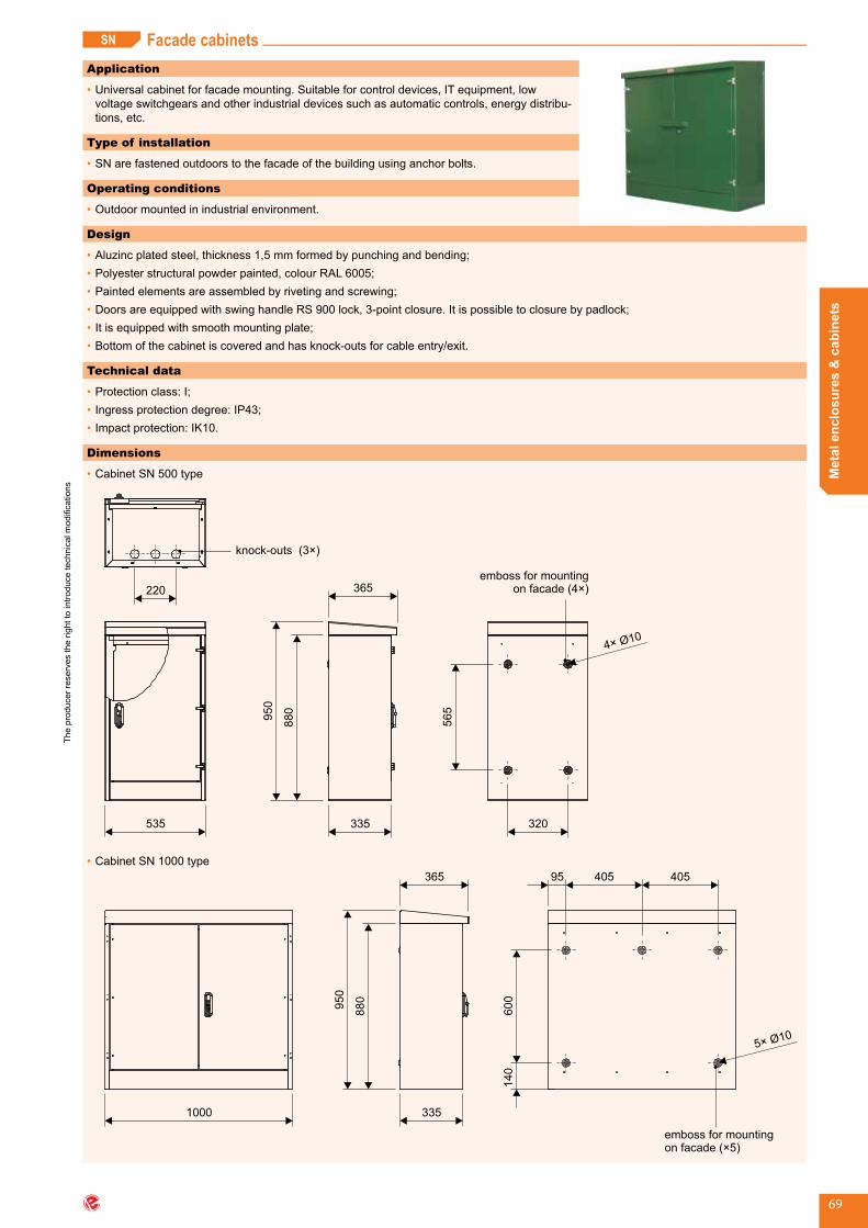
The
prod
ucer
rese
rves
the
right
to in
trodu
ce te
chni
cal m
odifi
catio
ns
Met
al e
nclo
sure
s &
cab
inet
s
69
SN Facade cabinetsApplication
•Universalcabinetforfacademounting.Suitableforcontroldevices,ITequipment,lowvoltageswitchgearsandotherindustrialdevicessuchasautomaticcontrols,energydistribu-tions,etc.
Type of installation
•SNarefastenedoutdoorstothefacadeofthebuildingusinganchorbolts.
Operating conditions
•Outdoormountedinindustrialenvironment.
Design
•Aluzincplatedsteel,thickness1,5mmformedbypunchingandbending;•Polyesterstructuralpowderpainted,colourRAL6005;•Paintedelementsareassembledbyrivetingandscrewing;•DoorsareequippedwithswinghandleRS900lock,3-pointclosure.Itispossibletoclosurebypadlock;•Itisequippedwithsmoothmountingplate;•Bottomofthecabinetiscoveredandhasknock-outsforcableentry/exit.
Technical data
•Protectionclass:I;•Ingressprotectiondegree:IP43;•Impactprotection:IK10.
Dimensions
•Cabinet SN 500 type
335
365
880
950
535
220
knock-outs (3 )×
320
565
emboss for mountingon facade (4 )×
•Cabinet SN 1000 type
335
365
1000
600
140
405 40595
emboss for mountingon facade ( 5)×
880
950
Facade cabinets (SN) SN_start

The
prod
ucer
rese
rves
the
right
to in
trodu
ce te
chni
cal m
odifi
catio
ns
www.emiter.com
Met
al e
nclo
sure
s &
cab
inet
s
70
SN
Reference chart
cabinet typedimensions [mm]
no.ofdoors knockoutsinthebottom knockouts spacing
width height depth
SN 500 535 880 335 1 3×Ø47 110SN 1000 1000 880 335 2 7×Ø47 110
How to order
•FacadecabinetSN500.
Scope of delivery
•Facadecabinet;•LockinsertforlockRS900withkeycode1333.
SN_end

The
prod
ucer
rese
rves
the
right
to in
trodu
ce te
chni
cal m
odifi
catio
ns
Met
al e
nclo
sure
s &
cab
inet
s
71
OWW Free-standing indoor cabinetsApplication
•Free-standing indoor cabinets, depending on mounted equipment, can be used for low voltageswitchgearsbuilding,controlcabinetsforsupervisionoftheproductionprocesses,asnetcabinetsintelecommunication.Cabinetscanbejoinedtogetherinsets.Incaseofswitchgear,onecanserveassupplypanel,thenextasoutletpanel,thenextasmeasuringpanel,etc.
Type of installation
•Cabinetsareplacedonthefloorandcanbejoinedtogetherinsets.
Operating conditions
•Indoor;•Lessextremeenvironment.
Dimension
•OWW cabinet, one door
s s1
w1
g
w
50
•OWW cabinet, two doors
s
w
50
g
Design
•Carbonsteel,thickness1,5mm,punched,bended,riveted,welded.Itispossibletouseothermaterials;•Polyesterstructuralpowderpainted,colourRAL7035;•Doorssuspendedonconcealedhinges,3-pointsclosure,swinghandlelockRS900;•Itisequippedwithsmoothmountingplate,madeofaluzincplatedsteel,thickness2mm.Itisset-upondepth;•AsoptioninsteadofmountingplatecanbeorderedmoduleunitZMoraccessoriesfor19’’devices(forwidth600mm);•Openedbottomforcableentrance/exit;•Cabinetismountedtothesocleusingbolts.Itispossibletoconnectcabinetsinseriesononesocle.
Technical data
•Protectionclass:I;•Ingressprotectiondegree:IP43;•Impactprotection:
- IK10-forsmooth,fulldoor, - IK08-forwindowdoor.
Free-standing indoor cabinets (OWW) OWW_start

The
prod
ucer
rese
rves
the
right
to in
trodu
ce te
chni
cal m
odifi
catio
ns
www.emiter.com
Met
al e
nclo
sure
s &
cab
inet
s
72
OWW
Reference chart
•OWW.........
cabinet type
dimensions [mm]
no.ofdoorswindow
dimensionss1×w1 [mm]
mounting plate
dimensions [mm]
width(s) height(w) depth(g)
OWW 40 160 40 400 1600 400 1 220×1420 300×1500OWW 40 160 50 400 1600 500 1 220×1420 300×1500OWW 40 160 60 400 1600 600 1 220×1420 300×1500OWW 40 180 40 400 1800 400 1 220×1620 300×1700OWW 40 180 50 400 1800 500 1 220×1620 300×1700OWW 40 180 60 400 1800 600 1 220×1620 300×1700OWW 40 200 40 400 2000 400 1 220×1820 300×1900OWW 40 200 50 400 2000 500 1 220×1820 300×1900OWW 40 200 60 400 2000 600 1 220×1820 300×1900OWW 60 160 40 600 1600 400 1 420×1420 500×1500OWW 60 160 50 600 1600 500 1 420×1420 500×1500OWW 60 160 60 600 1600 600 1 420×1420 500×1500OWW 60 180 40 600 1800 400 1 420×1620 500×1700OWW 60 180 50 600 1800 500 1 420×1620 500×1700OWW 60 180 60 600 1800 600 1 420×1620 500×1700OWW 60 200 40 600 2000 400 1 420×1820 500×1900OWW 60 200 50 600 2000 500 1 420×1820 500×1900OWW 60 200 60 600 2000 600 1 420×1820 500×1900OWW 80 160 40 800 1600 400 1 620×1420 700×1500OWW 80 160 50 800 1600 500 1 620×1420 700×1500OWW 80 160 60 800 1600 600 1 620×1420 700×1500OWW 80 180 40 800 1800 400 1 620×1620 700×1700OWW 80 180 50 800 1800 500 1 620×1620 700×1700OWW 80 180 60 800 1800 600 1 620×1620 700×1700OWW 80 200 40 800 2000 400 1 620×1820 700×1900OWW 80 200 50 800 2000 500 1 620×1820 700×1900OWW 80 200 60 800 2000 600 1 620×1820 700×1900OWW 100 180 40 1000 1800 400 2 2×281×1420 900×1700OWW 100 180 50 1000 1800 500 2 2×281×1420 900×1700OWW 100 180 60 1000 1800 600 2 2×281×1420 900×1700OWW 100 200 40 1000 2000 400 2 2×281×1820 900×1900OWW 100 200 50 1000 2000 500 2 2×281×1820 900×1900OWW 100 200 60 1000 2000 600 2 2×281×1820 900×1900OWW 120 180 40 1200 1800 400 2 2×381×1620 1100×1700OWW 120 180 50 1200 1800 500 2 2×381×1620 1100×1700OWW 120 180 60 1200 1800 600 2 2×381×1620 1100×1700OWW 120 200 40 1200 2000 400 2 2×381×1820 1100×1900OWW 120 200 50 1200 2000 500 2 2×381×1820 1100×1900OWW 120 200 60 1200 2000 600 2 2×381×1820 1100×1900

The
prod
ucer
rese
rves
the
right
to in
trodu
ce te
chni
cal m
odifi
catio
ns
Met
al e
nclo
sure
s &
cab
inet
s
73
OWW
•OWW.........ZM
cabinet type
dimensions [mm]
no.ofdoors
window dimensionss1×w1 [mm]
modular unit ZM
width(s) height(w) depth(g)
no.ofmodules
in masking panel
no.ofmasking
panelsinthemodular unit
sum of modules in themodular
unit
OWW 40 160 40 400 1600 400 1 220×1420 15 10 150OWW 40 160 50 400 1600 500 1 220×1420 15 10 150OWW 40 160 60 400 1600 600 1 220×1420 15 10 150OWW 40 180 40 400 1800 400 1 220×1620 15 11 165OWW 40 180 50 400 1800 500 1 220×1620 15 11 165OWW 40 180 60 400 1800 600 1 220×1620 15 11 165OWW 40 200 40 400 2000 400 1 220×1820 15 13 195OWW 40 200 50 400 2000 500 1 220×1820 15 13 195OWW 40 200 60 400 2000 600 1 220×1820 15 13 195OWW 60 160 40 600 1600 400 1 420×1420 26 10 260OWW 60 160 50 600 1600 500 1 420×1420 26 10 260OWW 60 160 60 600 1600 600 1 420×1420 26 10 260OWW 60 180 40 600 1800 400 1 420×1620 26 11 286OWW 60 180 50 600 1800 500 1 420×1620 26 11 286OWW 60 180 60 600 1800 600 1 420×1620 26 11 286OWW 60 200 40 600 2000 400 1 420×1820 26 13 338OWW 60 200 50 600 2000 500 1 420×1820 26 13 338OWW 60 200 60 600 2000 600 1 420×1820 26 13 338OWW 80 160 40 800 1600 400 1 620×1420 38 10 380OWW 80 160 50 800 1600 500 1 620×1420 38 10 380OWW 80 160 60 800 1600 600 1 620×1420 38 10 380OWW 80 180 40 800 1800 400 1 620×1620 38 11 418OWW 80 180 50 800 1800 500 1 620×1620 38 11 418OWW 80 180 60 800 1800 600 1 620×1620 38 11 418OWW 80 200 40 800 2000 400 1 620×1820 38 13 494OWW 80 200 50 800 2000 500 1 620×1820 38 13 494OWW 80 200 60 800 2000 600 1 620×1820 38 13 494OWW 100 180 40 1000 1800 400 2 2×281×1420 49 11 539OWW 100 180 50 1000 1800 500 2 2×281×1420 49 11 539OWW 100 180 60 1000 1800 600 2 2×281×1420 49 11 539OWW 100 200 40 1000 2000 400 2 2×281×1820 49 13 637OWW 100 200 50 1000 2000 500 2 2×281×1820 49 13 637OWW 100 200 60 1000 2000 600 2 2×281×1820 49 13 637OWW 120 180 40 1200 1800 400 2 2×381×1620 61 11 671OWW 120 180 50 1200 1800 500 2 2×381×1620 61 11 671OWW 120 180 60 1200 1800 600 2 2×381×1620 61 11 671OWW 120 200 40 1200 2000 400 2 2×381×1820 61 13 793OWW 120 200 50 1200 2000 500 2 2×381×1820 61 13 793OWW 120 200 60 1200 2000 600 2 2×381×1820 61 13 793
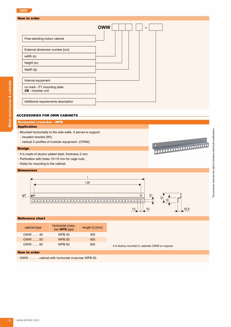
The
prod
ucer
rese
rves
the
right
to in
trodu
ce te
chni
cal m
odifi
catio
ns
www.emiter.com
Met
al e
nclo
sure
s &
cab
inet
s
74
OWW
Application
•Mountedhorizontallytothesidewalls.Itservestosupport: - insulatorbracket(WI); - verticalC-profilesofmodularequipment(CPAM).
Design
•Itismadeofaluzincplatedsteel,thickness2mm;•Perforationwithholes10×10mmforcagenuts;•Holesformountingtothecabinet.
How to order
OWW
width (s)
height (w)
External dimension number [cm]
depth (g)
Free-standing indoor cabinet
Additional requirements description
-
Internal equipment
no mark - P1 mounting plate
- modular unitZM
Horizontal cross-bar - WPB
Dimensions
15,5
l-28
l
22
1013
10
42
Reference chart
cabinet type horizontalcross-bar WPB type length(l)[mm]
OWW......40 WPB 40 300OWW......50 WPB 50 400OWW......60 WPB 60 500
How to order
•OWW.........cabinetwithhorizontalcross-barWPB50.
It is factory mounted in cabinets OWW on request.
ACCESSORIES FOR OWW CABINETS
Accessories for OWW cabinets

The
prod
ucer
rese
rves
the
right
to in
trodu
ce te
chni
cal m
odifi
catio
ns
Met
al e
nclo
sure
s &
cab
inet
s
75
OWW
Application
•Mountedverticallytothecross-barsWPB;•Suitableformountinginsulatorstocurrentbusbars.
Design
•Itismadeofaluzincplatedsteel,thickness2mm;•PerforationwithholesØ12mmforinsulators;•Perforationwithoblongholes6×12mmformountingtohorizontalcross-bars.
Dimensions
l
37
256
6
21
103
0
20
24
Insulators bracket - WI
Reference chart
cabinet type insulators bracket WI type length(l)[mm]
OWW...160... WPB 40 1560OWW...180... WPB 50 1760OWW...200... WPB 60 1960
How to order
•InsulatorsbracketWI200.
Brackets come in pairs.

The
prod
ucer
rese
rves
the
right
to in
trodu
ce te
chni
cal m
odifi
catio
ns
www.emiter.com
Met
al e
nclo
sure
s &
cab
inet
s
76
OWW
Application
•Mountedhorizontallytothesidewallsofthecabinet;•ItservestomountcableholderUKtype.
Design
•Itismadeofaluzincplatedsteel,thickness2mm;•Perforatedwithoblongholes12×24mm,formountingUKcableholder.
Side bracket of cable holder - WUK
Dimensions
35,6
48
88
l-30
l
1227
R6
10
Reference chart
cabinet typeside bracket of
cableholderWUKtype
length(l)[mm]
OWW......40 WPB 40 300OWW......50 WPB 50 400OWW......60 WPB 60 500 It is factory mounted in the OWW cabinets on request.
OWW_end

The
prod
ucer
rese
rves
the
right
to in
trodu
ce te
chni
cal m
odifi
catio
ns
Met
al e
nclo
sure
s &
cab
inet
s
77
Universal control cabinetsSSU
Application
•Universal control cabinets, depending on mounted equipment, can be used for low voltage switchgearsbuilding,controlcabinetsforsupervisionoftheproductionprocesses,asnetcabinetsfortelecommunication.Cabinetscanbejoinedtogetherinsets.
Type of installation
•Cabinetsareplacedonthefloor.
Operating conditions
•Indoor;•Lessextremeenvironment.
Design
•Carbonsteel,thickness1,5mm,punched,bended,riveted,welded;•Polyesterstructuralpowderpainted,colourRAL7035;•Socleismadeofcarbonsteel,thickness2mm,boltedtothecabinet;•Nesteddoors,suspendedonconcealedhinges,openingangle130°;•3-pointclosingsystemofthedoors,RS900lockwithswinghandlecamandroundbars;•Smoothmountingplatemadeofaluzincplatedsteel,thickness2mm;•Openedbottomforcableentrance/exit;•Options:liftingrings,adjustablefeet,ventilationlouvers,cableglandplate,etc.
Dimensions
•SSU cabinet
s
w
100
g
•Mounting plate
a
b
Technical data
•Protectionclass:I;•Ingressprotectiondegree:IP43;•Impactprotection:IK10(full,smoothdoors).
Universal control cabinets (SSU) SSU_start

The
prod
ucer
rese
rves
the
right
to in
trodu
ce te
chni
cal m
odifi
catio
ns
www.emiter.com
Met
al e
nclo
sure
s &
cab
inet
s
78
SSU
Reference chart
cabinet type
dimensions [mm]
no.ofdoors
mounting plate
dimensions [mm]
width(s) height(w) depth(g)
SSU 60 100 40 600 1000 400 1 525×910SSU 60 100 50 600 1000 500 1 525×910SSU 60 120 40 600 1200 400 1 525×1110SSU 60 120 50 600 1200 500 1 525×1110SSU 60 140 40 600 1400 400 1 525×1310SSU 60 140 50 600 1400 500 1 525×1310SSU 60 160 40 600 1600 400 1 525×1510SSU 60 160 50 600 1600 500 1 525×1510SSU 60 180 40 600 1800 400 1 525×1710SSU 60 180 50 600 1800 500 1 525×1710SSU 60 200 40 600 2000 400 1 525×1910SSU 60 200 50 600 2000 500 1 525×1910SSU 80 100 40 800 1000 400 1 725×910SSU 80 100 50 800 1000 500 1 725×910SSU 80 120 40 800 1200 400 1 725×1110SSU 80 120 50 800 1200 500 1 725×1110SSU 80 140 40 800 1400 400 1 725×1310SSU 80 140 50 800 1400 500 1 725×1310SSU 80 160 40 800 1600 400 1 725×1510SSU 80 160 50 800 1600 500 1 725×1510SSU 80 180 40 800 1800 400 1 725×1710SSU 80 180 50 800 1800 500 1 725×1710SSU 80 200 40 800 2000 400 1 725×1910SSU 80 200 50 800 2000 500 1 725×1910SSU 100 100 40 1000 1000 400 2 925×910SSU 100 100 50 1000 1000 500 2 925×910SSU 100 120 40 1000 1200 400 2 925×1110SSU 100 120 50 1000 1200 500 2 925×1110SSU 100 140 40 1000 1400 400 2 925×1310SSU 100 140 50 1000 1400 500 2 925×1310SSU 100 160 40 1000 1600 400 2 925×1510SSU 100 160 50 1000 1600 500 2 925×1510SSU 100 180 40 1000 1800 400 2 925×1710SSU 100 180 50 1000 1800 500 2 925×1710SSU 100 200 40 1000 2000 400 2 925×1910SSU 100 200 50 1000 2000 500 2 925×1910SSU 120 100 40 1200 1000 400 2 1125×910SSU 120 100 50 1200 1000 500 2 1125×910SSU 120 120 40 1200 1200 400 2 1125×1110SSU 120 120 50 1200 1200 500 2 1125×1110SSU 120 140 40 1200 1400 400 2 1125×1310SSU 120 140 50 1200 1400 500 2 1125×1310SSU 120 160 40 1200 1600 400 2 1125×1510SSU 120 160 50 1200 1600 500 2 1125×1510SSU 120 180 40 1200 1800 400 2 1125×1710SSU 120 180 50 1200 1800 500 2 1125×1710SSU 120 200 40 1200 2000 400 2 1125×1910SSU 120 200 50 1200 2000 500 2 1125×1910

The
prod
ucer
rese
rves
the
right
to in
trodu
ce te
chni
cal m
odifi
catio
ns
Met
al e
nclo
sure
s &
cab
inet
s
79
SSU
How to order
SSU
width (s)
height (w)
External domension number [cm]
depth (g)
Universal control cabinet
-
Additional requirements description
•Orderingexample: - UniversalcontrolcabinetSSU12020050.
Scope of delivery
•SSUcabinet;•LockinsertforlockRS900withkey(code1333).
SSU_end
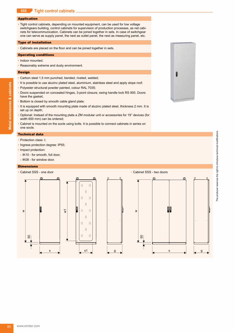
The
prod
ucer
rese
rves
the
right
to in
trodu
ce te
chni
cal m
odifi
catio
ns
www.emiter.com
Met
al e
nclo
sure
s &
cab
inet
s
80
Tight control cabinetsSSS
Application
•Tightcontrolcabinets,dependingonmountedequipment,canbeusedforlowvoltageswitchgearsbuilding,controlcabinetsforsupervisionofproductionprocesses,asnetcabi-netsfortelecommunication.Cabinetscanbejoinedtogetherinsets.Incaseofswitchgearonecanserveassupplypanel,thenextasoutletpanel,thenextasmeasuringpanel,etc.
Type of installation
•Cabinetsareplacedonthefloorandcanbejoinedtogetherinsets.
Operating conditions
•Indoormounted;•Reasonablyextremeanddustyenvironment.
Design
•Carbonsteel1,5mmpunched,bended,riveted,welded;•Itispossibletousealuzincplatedsteel,aluminium,stainlesssteelandapplysloperoof;•Polyesterstructuralpowderpainted,colourRAL7035;•Doorssuspendedonconcealedhinges,3-piontclosure,swinghandlelockRS900.Doorshavethegasket;
•Bottomisclosedbysmoothcableglandplate;•Itisequippedwithsmoothmountingplatemadeofaluzincplatedsteel,thickness2mm.Itissetupondepth;
•Optional:InsteadofthemountingplateaZMmodularunitoraccessoriesfor19’’devices(forwidth600mm)canbeordered;
•Cabinetismountedonthesocleusingbolts.Itispossibletoconnectcabinetsinseriesononesocle.
Technical data
•Protectionclass:I;•Ingressprotectiondegree:IP55;•Impactprotection:
- IK10-forsmooth,fulldoor, - IK08-forwindowdoor.
Dimensions
•Cabinet SSS - one door
s s1
w1
g
w
50
•Cabinet SSS - two doors
s
w
50
g
Tight control cabinets (SSS) SSS_start

The
prod
ucer
rese
rves
the
right
to in
trodu
ce te
chni
cal m
odifi
catio
ns
Met
al e
nclo
sure
s &
cab
inet
s
81
Reference chart
•SSS.........
cabinet type
dimensions [mm]
no.ofdoorswindow
dimensionss1×w1 [mm]
mounting plate
dimensions [mm]
width(s) height(w) depth(g)
SSS 40 160 40 400 1600 400 1 220×1420 300×1500SSS 40 160 50 400 1600 500 1 220×1420 300×1500SSS 40 160 60 400 1600 600 1 220×1420 300×1500SSS 40 180 40 400 1800 400 1 220×1620 300×1700SSS 40 180 50 400 1800 500 1 220×1620 300×1700SSS 40 180 60 400 1800 600 1 220×1620 300×1700SSS 40 200 40 400 2000 400 1 220×1820 300×1900SSS 40 200 50 400 2000 500 1 220×1820 300×1900SSS 40 200 60 400 2000 600 1 220×1820 300×1900SSS 60 160 40 600 1600 400 1 420×1420 500×1500SSS 60 160 50 600 1600 500 1 420×1420 500×1500SSS 60 160 60 600 1600 600 1 420×1420 500×1500SSS 60 180 40 600 1800 400 1 420×1620 500×1700SSS 60 180 50 600 1800 500 1 420×1620 500×1700SSS 60 180 60 600 1800 600 1 420×1620 500×1700SSS 60 200 40 600 2000 400 1 420×1820 500×1900SSS 60 200 50 600 2000 500 1 420×1820 500×1900SSS 60 200 60 600 2000 600 1 420×1820 500×1900SSS 80 160 40 800 1600 400 1 620×1420 700×1500SSS 80 160 50 800 1600 500 1 620×1420 700×1500SSS 80 160 60 800 1600 600 1 620×1420 700×1500SSS 80 180 40 800 1800 400 1 620×1620 700×1700SSS 80 180 50 800 1800 500 1 620×1620 700×1700SSS 80 180 60 800 1800 600 1 620×1620 700×1700SSS 80 200 40 800 2000 400 1 620×1820 700×1900SSS 80 200 50 800 2000 500 1 620×1820 700×1900SSS 80 200 60 800 2000 600 1 620×1820 700×1900SSS 100 180 40 1000 1800 400 2 2×281×1420 900×1700SSS 100 180 50 1000 1800 500 2 2×281×1420 900×1700SSS 100 180 60 1000 1800 600 2 2×281×1420 900×1700SSS 100 200 40 1000 2000 400 2 2×281×1820 900×1900SSS 100 200 50 1000 2000 500 2 2×281×1820 900×1900SSS 100 200 60 1000 2000 600 2 2×281×1820 900×1900SSS 120 180 40 1200 1800 400 2 2×381×1620 1100×1700SSS 120 180 50 1200 1800 500 2 2×381×1620 1100×1700SSS 120 180 60 1200 1800 600 2 2×381×1620 1100×1700SSS 120 200 40 1200 2000 400 2 2×381×1820 1100×1900SSS 120 200 50 1200 2000 500 2 2×381×1820 1100×1900SSS 120 200 60 1200 2000 600 2 2×381×1820 1100×1900
SSS

The
prod
ucer
rese
rves
the
right
to in
trodu
ce te
chni
cal m
odifi
catio
ns
www.emiter.com
Met
al e
nclo
sure
s &
cab
inet
s
82
•SSS.........ZM
cabinet type
dimensions [mm]
no.ofdoors
window dimensionss1×w1 [mm]
modular unit ZM
width(s) height(w) depth(g)
no.ofmodules
in masking panel
no.ofmasking
panelsinthemodular unit
sum of modules in themodular
unit
SSS 40 160 40 400 1600 400 1 220×1420 15 10 150SSS 40 160 50 400 1600 500 1 220×1420 15 10 150SSS 40 160 60 400 1600 600 1 220×1420 15 10 150SSS 40 180 40 400 1800 400 1 220×1620 15 11 165SSS 40 180 50 400 1800 500 1 220×1620 15 11 165SSS 40 180 60 400 1800 600 1 220×1620 15 11 165SSS 40 200 40 400 2000 400 1 220×1820 15 13 195SSS 40 200 50 400 2000 500 1 220×1820 15 13 195SSS 40 200 60 400 2000 600 1 220×1820 15 13 195SSS 60 160 40 600 1600 400 1 420×1420 26 10 260SSS 60 160 50 600 1600 500 1 420×1420 26 10 260SSS 60 160 60 600 1600 600 1 420×1420 26 10 260SSS 60 180 40 600 1800 400 1 420×1620 26 11 286SSS 60 180 50 600 1800 500 1 420×1620 26 11 286SSS 60 180 60 600 1800 600 1 420×1620 26 11 286SSS 60 200 40 600 2000 400 1 420×1820 26 13 338SSS 60 200 50 600 2000 500 1 420×1820 26 13 338SSS 60 200 60 600 2000 600 1 420×1820 26 13 338SSS 80 160 40 800 1600 400 1 620×1420 38 10 380SSS 80 160 50 800 1600 500 1 620×1420 38 10 380SSS 80 160 60 800 1600 600 1 620×1420 38 10 380SSS 80 180 40 800 1800 400 1 620×1620 38 11 418SSS 80 180 50 800 1800 500 1 620×1620 38 11 418SSS 80 180 60 800 1800 600 1 620×1620 38 11 418SSS 80 200 40 800 2000 400 1 620×1820 38 13 494SSS 80 200 50 800 2000 500 1 620×1820 38 13 494SSS 80 200 60 800 2000 600 1 620×1820 38 13 494SSS 100 180 40 1000 1800 400 2 2×281×1420 49 11 539SSS 100 180 50 1000 1800 500 2 2×281×1420 49 11 539SSS 100 180 60 1000 1800 600 2 2×281×1420 49 11 539SSS 100 200 40 1000 2000 400 2 2×281×1820 49 13 637SSS 100 200 50 1000 2000 500 2 2×281×1820 49 13 637SSS 100 200 60 1000 2000 600 2 2×281×1820 49 13 637SSS 120 180 40 1200 1800 400 2 2×381×1620 61 11 671SSS 120 180 50 1200 1800 500 2 2×381×1620 61 11 671SSS 120 180 60 1200 1800 600 2 2×381×1620 61 11 671SSS 120 200 40 1200 2000 400 2 2×381×1820 61 13 793SSS 120 200 50 1200 2000 500 2 2×381×1820 61 13 793SSS 120 200 60 1200 2000 600 2 2×381×1820 61 13 793
SSS

The
prod
ucer
rese
rves
the
right
to in
trodu
ce te
chni
cal m
odifi
catio
ns
Met
al e
nclo
sure
s &
cab
inet
s
83
How to order
SSS
width (s)
height (w)
External dimension number [cm]
depth (g)
Tight control cabinet
Additional requirements description
-
Internal equipment
no mark - P1 mounting plate
- modular unitZM
•Orderingexample: - TightcontrolcabinetSSS6018040.
Scope of delivery
•SSScabinet;•LockinsertforlockRS900withkey(code1333).
SSS
Application
•Mountedhorizontallytothesidewalls.Itservestosupport: - insulatorbracket(WI); - verticalC-profilesofmodularequipment(CPAM).
Design
•Itismadeofaluzincplatedsteel,thickness2mm;•Perforationwithholes10×10mmforcagenuts;•Holesformountingtothecabinet.
Horizontal cross-bar - WPB
Dimensions
15,5
l-28
l
22
1013
10
42
Reference chart
cabinet type horizontalcross- -bar WPB type length(l)[mm]
OWW......40 WPB 40 300OWW......50 WPB 50 400OWW......60 WPB 60 500
How to order
•OWW.........cabinetwithhorizontalcross-barWPB50.
It is factory mounted in cabinets OWW on request.
ACCESSORIES FOR SSS CABINETS Accessories for SSS cabinets

The
prod
ucer
rese
rves
the
right
to in
trodu
ce te
chni
cal m
odifi
catio
ns
www.emiter.com
Met
al e
nclo
sure
s &
cab
inet
s
84
Application
•Mountedverticallytothecross-barsWPB;•Itservestomountinsulatorforcurrentbusbars.
Design
•Itismadeofaluzincplatedsteel,thickness2mm;•PerforationwithholesØ12mmforinsulators;•Perforationwithoblongholes6×12mmformountingtohorizontalcross-bars.
Dimensions
l
37
256
6
21
103
0
20
24
Insulators bracket - WI
Reference chart
cabinet type insulators bracket WI type length(l)[mm]
OWW...160... WPB 40 1560OWW...180... WPB 50 1760OWW...200... WPB 60 1960
How to order
•InsulatorsbracketWI200.
Brackets comes in pairs with mounting elements.
SSS

The
prod
ucer
rese
rves
the
right
to in
trodu
ce te
chni
cal m
odifi
catio
ns
Met
al e
nclo
sure
s &
cab
inet
s
85
Application
•Mountedhorizontallytothesidewallsofthecabinet;•ItservestomountcableholderUKtype.
Design
•Itismadeofaluzincplatedsteel,thickness2mm;•Perforatedwithoblongholes12×24mm,formountingUKcableholder.
Side bracket for cable holder - WUK
Dimensions
35,6
48
88
l-30
l
1227
R6
10
Reference chart
cabinet typeside bracket of
cableholderWUKtype
length(l)[mm]
OWW......40 WPB 40 300OWW......50 WPB 50 400OWW......60 WPB 60 500 It is factory mounted in the OWW cabinets on request.
Application
•ForSSScabinetsdestinedforoutdoormounting.Itisfixedonoriginalflatroofofthecabinetusingbolts.
Design
•Madeofaluzincplatedsteel,thickness1,5mm;•Painting:likethecabinet.
Slope roof - DS
Dimensions
view from the bottom
50
g+
55
s+20 120
cage nuts 6×M8
SSS
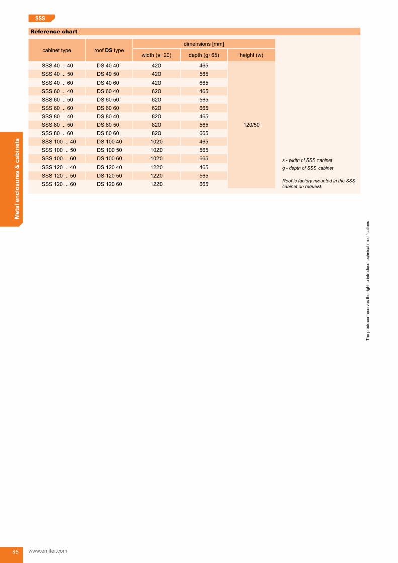
The
prod
ucer
rese
rves
the
right
to in
trodu
ce te
chni
cal m
odifi
catio
ns
www.emiter.com
Met
al e
nclo
sure
s &
cab
inet
s
86
Reference chart
cabinet type roof DS typedimensions [mm]
width(s+20) depth(g+65) height(w)
SSS40...40 DS 40 40 420 465
120/50
SSS40...50 DS 40 50 420 565SSS40...60 DS 40 60 420 665SSS60...40 DS 60 40 620 465SSS60...50 DS 60 50 620 565SSS60...60 DS 60 60 620 665SSS80...40 DS 80 40 820 465SSS80...50 DS 80 50 820 565SSS80...60 DS 80 60 820 665SSS100...40 DS 100 40 1020 465SSS100...50 DS 100 50 1020 565SSS100...60 DS 100 60 1020 665SSS120...40 DS 120 40 1220 465SSS120...50 DS 120 50 1220 565SSS120...60 DS 120 60 1220 665 Roof is factory mounted in the SSS
cabinet on request.
s - width of SSS cabinetg - depth of SSS cabinet
SSS
SSS_end

The
prod
ucer
rese
rves
the
right
to in
trodu
ce te
chni
cal m
odifi
catio
ns
Met
al e
nclo
sure
s &
cab
inet
s
87
PSA Control desksPSA
Application
•Theyaredesignedformountingcontrolapparatus,monitoringsystems,measurement andvisualisationdevicesofproductionprocessing;
•Theyarerecommendedforoperationstations,automatedprocessinglinesormachineryrooms.
Type of installation
•Itisplacedonthefloorandfixedusingdowelbolts.
Operating conditions
•Indoormounted;•Mediumaggressiveanddustyenvironment.
Design
•Carbonsteel1,5mmpunched,bended,welded;•Polyesterstructuralpowderpainted,colourRAL7035;•Facadepanelsanddoorssuspendedonconcealedhinges,enabletomaintenancemountedapparatus.EquippedwithlocksforD3keyandpolyurethaneseals;
•Backcoverswithseals,fixedusingscrews;•Mountingplatesmadeof2mmthickaluzincplatedsteel,depthissetup(inverticalparts);•Twocrossperforatedprofiles(inhorizontalparts);•Socle100mm;•Itispossibleonrequesttomakeperforationunderapparatusoffacadepanel;
Technical data
•Protectionclass:I;•Ingressprotectiondegree:IP55;•Impactprotection:IK10.
Dimensions
g-120
s g 530
500
1350
850
100
Control desks (PSA) PSA_start

The
prod
ucer
rese
rves
the
right
to in
trodu
ce te
chni
cal m
odifi
catio
ns
www.emiter.com
Met
al e
nclo
sure
s &
cab
inet
s
88
PSA
Reference chart
desk typedimensions [mm]
doorswidth(s) depth(g)
PSA 60 45 600 450 1-wingPSA 60 60 600 600 1-wingPSA 60 80 600 800 1-wingPSA 80 45 800 450 1-wingPSA 80 60 800 600 1-wingPSA 80 80 800 800 1-wingPSA 100 45 1000 450 2-wingsPSA 100 60 1000 600 2-wingsPSA 100 80 1000 800 2-wingsPSA 120 45 1200 450 2-wingsPSA 120 60 1200 600 2-wingsPSA 120 80 1200 800 2-wingsPSA 150 45 1500 450 2-wingsPSA 150 60 1500 600 2-wingsPSA 150 80 1500 800 2-wings
How to order
PSA
width (s)
depth (g)
External dimension number [cm]
Control desk A type
Additional requirements description
-
•Orderingexample: - ControldeskPSA10045.
Scope of delivery
•Controldesk;•Doublebitkey.

The
prod
ucer
rese
rves
the
right
to in
trodu
ce te
chni
cal m
odifi
catio
ns
Met
al e
nclo
sure
s &
cab
inet
s
89
PSBPSA Control desksPSB
Application
•Theyaredesignedformountingcontrolapparatus,monitoringsystems,measurement andvisualisationdevicesofproductionprocessing;
•Theyarerecommendedforoperationstations,automatedprocessinglinesormachineryrooms.
Type of installation
•Itisplacedonthefloorandfixedusingdowelbolts.
Operating conditions
•Indoormounted;•Mediumaggressiveanddustyenvironment.
Design
•Carbonsteel1,5mmpunched,bended,welded;•Polyesterstructuralpowderpainted,colourRAL7035;•Facadepanelsanddoorssuspendedonconcealedhinges,enabletomaintenancemountedapparatus.EquippedwithlocksforD3keyandpolyurethaneseals;
•Backcoverswithseals,fixedusingscrews;•Mountingplatesmadeof2mmthickaluzincplatedsteel,depthisset-up(inverticalparts);•Twocrossperforatedprofiles(inhorizontalparts);•Socle100mm;•Itispossibleonrequesttomakeperforationunderapparatusoffacadepanels.
Technical data
•Protectionclass:I;•Ingressprotectiondegree:IP55;•Impactprotection:IK10.
Dimensions
s g
970
600
100
g+530
160
Control desks (PSB)

The
prod
ucer
rese
rves
the
right
to in
trodu
ce te
chni
cal m
odifi
catio
ns
www.emiter.com
Met
al e
nclo
sure
s &
cab
inet
s
90
PSB
Reference chart
desk typedimensions [mm]
doorswidth(s) depth(g)
PSA 60 45 600 450 1-wingPSA 60 60 600 600 1-wingPSA 80 45 800 450 1-wingPSA 80 60 800 600 1-wingPSA 100 45 1000 450 2-wingsPSA 100 60 1000 600 2-wingsPSA 120 45 1200 450 2-wingsPSA 120 60 1200 600 2-wingsPSA 150 45 1500 450 2-wingsPSA 150 60 1500 600 2-wings
How to order
PSB
width (s)
depth (g)
External dimension number [cm]
Control desk B type
Additional requirements description
-
•Orderingexample: - ControldeskPSB15060.
Scope of delivery
•Controldesk;•Doublebitkey.
PSA_end
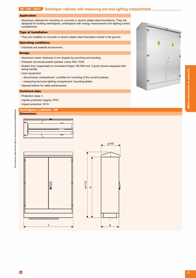
The
prod
ucer
rese
rves
the
right
to in
trodu
ce te
chni
cal m
odifi
catio
ns
Met
al e
nclo
sure
s &
cab
inet
s
91
Switchgear cabinets with measuring and area lighting compartmentsSK • SKP • SKPO
Application
•Aluminiumcabinetsformountingonconcreteoraluzincplatedsteelfoundations.Theyaredesignedforbuildingswitchgears,switchgearswithenergymeasurementandlightingcontrolcompartment.
Type of installation
•Theyareinstalledonconcreteoraluzincplatedsteelfoundationburiedintheground.
Operating conditions
•Industrialandseasideenvironment.
Design
•Aluminiumsheet,thickness2mmshapedbypunchingandbending;•Polyesterstructuralpowderpainted,colourRAL7035;•Nesteddoorsuspendedonconcealedhinges,RS900lock,3-pointclosureequippedwithswinghandle;
•Innerequipment: - disconnectorcompartment:c-profilesformountingofthecurrentbusbars, - measuringandarealightingcompartment:mountingplates;
•Openedbottomforcableentrance/exit.
Technical data
•Protectionclass:I;•Ingressprotectiondegree:IP44;•Impactprotection:IK10.
Dimensions
s
w+
112
w
g+30
g
Switchgears cabinets - SK
Switchgear cabinets with measuring and area lighting compartments (SK, SKP, SKPO) SK_start
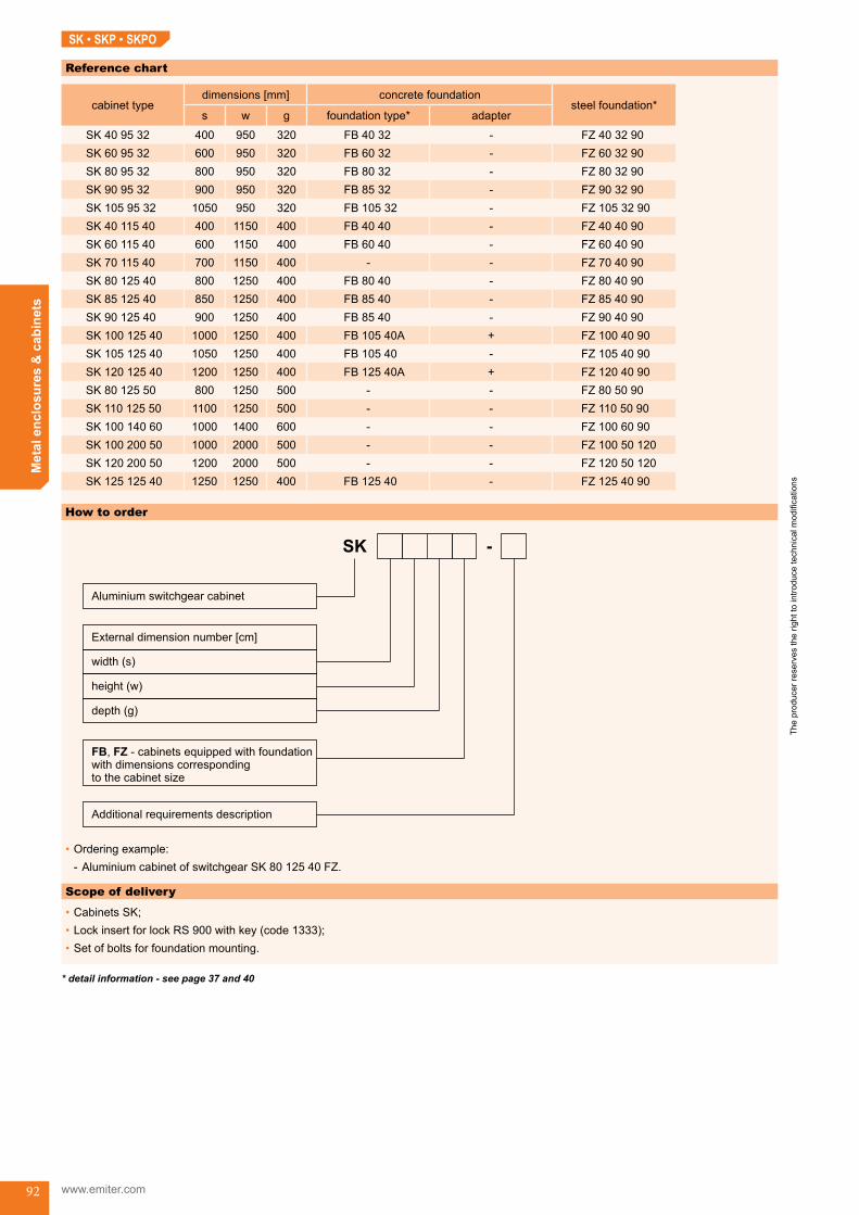
The
prod
ucer
rese
rves
the
right
to in
trodu
ce te
chni
cal m
odifi
catio
ns
www.emiter.com
Met
al e
nclo
sure
s &
cab
inet
s
92
SK • SKP • SKPO
Reference chart
cabinet typedimensions [mm] concrete foundation
steel foundation*s w g foundation type* adapter
SK 40 95 32 400 950 320 FB 40 32 - FZ 40 32 90SK 60 95 32 600 950 320 FB 60 32 - FZ 60 32 90SK 80 95 32 800 950 320 FB 80 32 - FZ 80 32 90SK 90 95 32 900 950 320 FB 85 32 - FZ 90 32 90SK 105 95 32 1050 950 320 FB 105 32 - FZ 105 32 90SK 40 115 40 400 1150 400 FB 40 40 - FZ 40 40 90SK 60 115 40 600 1150 400 FB 60 40 - FZ 60 40 90SK 70 115 40 700 1150 400 - - FZ 70 40 90SK 80 125 40 800 1250 400 FB 80 40 - FZ 80 40 90SK 85 125 40 850 1250 400 FB 85 40 - FZ 85 40 90SK 90 125 40 900 1250 400 FB 85 40 - FZ 90 40 90SK 100 125 40 1000 1250 400 FB 105 40A + FZ 100 40 90SK 105 125 40 1050 1250 400 FB 105 40 - FZ 105 40 90SK 120 125 40 1200 1250 400 FB 125 40A + FZ 120 40 90SK 80 125 50 800 1250 500 - - FZ 80 50 90SK 110 125 50 1100 1250 500 - - FZ 110 50 90SK 100 140 60 1000 1400 600 - - FZ 100 60 90SK 100 200 50 1000 2000 500 - - FZ 100 50 120SK 120 200 50 1200 2000 500 - - FZ 120 50 120SK 125 125 40 1250 1250 400 FB 125 40 - FZ 125 40 90
How to order
•Orderingexample: - AluminiumcabinetofswitchgearSK 80 125 40 FZ.
Scope of delivery
•CabinetsSK;•LockinsertforlockRS900withkey(code1333);•Setofboltsforfoundationmounting.
* detail information - see page 37 and 40

The
prod
ucer
rese
rves
the
right
to in
trodu
ce te
chni
cal m
odifi
catio
ns
Met
al e
nclo
sure
s &
cab
inet
s
93
Switchgear cabinets with measuring compartment - SKPDimensions
w+
112
w
g+30
gs
s1 s2
switchgear (ZK) measuring compartment (P)
Reference chart
cabinet typedimensions [mm]
foundation type*s1 s2 s w g
SKP 40 125 40 400 450 850 1250 400 FB 85 40SKP 60 125 40 600 450 1050 1250 400 FB 105 40SKP 70 125 40 700 450 1150 1250 400 FB 105 40SKP 80 125 40 800 450 1250 1250 400 FB 125 40SKP 85 125 40 850 450 1300 1250 400 FB 125 40SKP 90 125 40 900 450 1350 1250 400 FB 125 40
SKP 95 125 40 950 450 1400 1250 400 FB 80 40 +FB 60 40
SKP 100 125 40 1000 450 1450 1250 400 FB 85 40 +FB 60 40
SKP 105 125 40 1050 450 1500 1250 400 FB 85 40 +FB 60 40
SKP 110 125 40 1100 450 1550 1250 400 FB 85 40 +FB 60 40
SKP 120 125 40 1200 450 1650 1250 400 FB 85 40 +FB 80 40
SK • SKP • SKPO
* detail information - see page 40
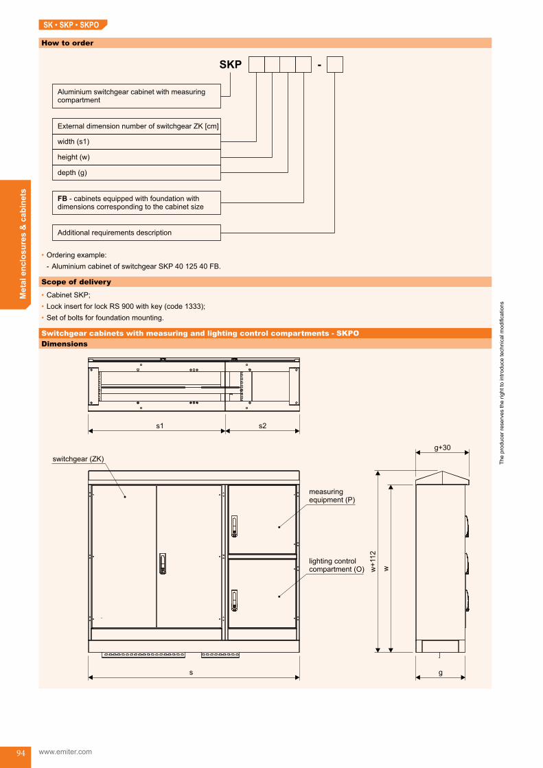
The
prod
ucer
rese
rves
the
right
to in
trodu
ce te
chni
cal m
odifi
catio
ns
www.emiter.com
Met
al e
nclo
sure
s &
cab
inet
s
94
How to order
•Orderingexample: - AluminiumcabinetofswitchgearSKP40 125 40 FB.
Scope of delivery
•CabinetSKP;•LockinsertforlockRS900withkey(code1333);•Setofboltsforfoundationmounting.
Switchgear cabinets with measuring and lighting control compartments - SKPODimensions
s g
w+
112
w
g+30
s1 s2
lighting controlcompartment (O)
measuringequipment (P)
switchgear (ZK)
SK • SKP • SKPO

The
prod
ucer
rese
rves
the
right
to in
trodu
ce te
chni
cal m
odifi
catio
ns
Met
al e
nclo
sure
s &
cab
inet
s
95
SK • SKP • SKPO
Reference chart
cabinet typedimensions [mm]
foundation type*s1 s2 s w g
SKPO 40 125 40 400 550 950 1250 400 FB 85 40SKPO 60 125 40 600 550 1150 1250 400 FB 105 40SKPO 70 125 40 700 550 1250 1250 400 FB 125 40SKPO 80 125 40 800 550 1350 1250 400 FB 125 40
SKPO 85 125 40 850 550 1400 1250 400 FB 80 40 +FB 60 40
SKPO 90 125 40 900 550 1450 1250 400 FB 80 40 +FB 60 40
SKPO 95 125 40 950 550 1500 1250 400 FB 85 40 +FB 60 40
SKPO 100 125 40 1000 550 1550 1250 400 FB 80 40 +FB 80 40
SKPO 105 125 40 1050 550 1600 1250 400 FB 80 40 +FB 80 40
SKPO 110 125 40 1100 550 1650 1250 400 FB 80 40 +FB 80 40
SKPO 120 125 40 1200 550 1750 1250 400 FB 85 40 +FB 85 40
How to order
•Orderingexample: - AluminiumcabinetofswitchgearSKPO 95 125 40 FB
Scope of delivery
•CabinetSKPO;•LockinsertforlockRS900withkey(code1333);•Setofboltsforfoundationmounting.
* detail information - see page 40
SK_end

The
prod
ucer
rese
rves
the
right
to in
trodu
ce te
chni
cal m
odifi
catio
ns
www.emiter.com
Met
al e
nclo
sure
s &
cab
inet
s
96
SWAP • SWAPO Tower switchgear cabinetsApplication
•Aluminiumcabinetsforflushmountinginthewalloftowertransformerstation.Outdooraccess.Indooraccessprotectedbyperforatedremovablecover.
Type of installation
•Inthenestofthetowertransformerstationwall.
Operating conditions
•Industrialandseasideenvironment.
Design
•Aluminiumsheet,thickness2mm,shapedbypunchingandbending;•Polyesterstructuralpowderpainted,colourRAL7035;•Nesteddoorsuspendedonconcealedhinges,RS900lockswithswinghandle,1-and3-pointclosure;•Cabinetcompartments:
- disconnectorcompartment:equippedwithbracketformountingbusbarsupports, - measuringandlightingcompartmentsequippedwithmountingplates.
Technical data
•Protectionclass:I;•Ingressprotectiondegree:IP44;•Impactprotection:IK10.
Dimensions
•SWAP cabinet
g
w
disconnector compartment measuring compartment masking frame
s1 s2
s
s+109
w+
109
SWA... cabinet - rear view
Tower switchgear cabinets (SWAP, SWAPO) SWAP_start
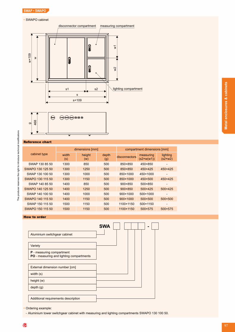
The
prod
ucer
rese
rves
the
right
to in
trodu
ce te
chni
cal m
odifi
catio
ns
Met
al e
nclo
sure
s &
cab
inet
s
97
SWAP • SWAPO
•SWAPO cabinet
w
w+
109
disconnector compartment
lighting compartment
468
gmeasuring compartment
w2
w1
Reference chart
cabinet typedimensions [mm] compartment dimensions [mm]
width(s)
height(w)
depth(g) disconnectors measuring
(s2×w(w1))lighting(s2×w2)
SWAP 130 85 50 1300 850 500 850×850 450×850 -SWAPO 130 125 50 1300 1250 500 850×850 450×425 450×425
SWAP 130 100 50 1300 1000 500 850×1000 450×1000 -SWAPO 130 115 50 1300 1150 500 850×1000 450×500 450×425
SWAP 140 85 50 1400 850 500 900×850 500×850 -SWAPO 140 125 50 1400 1250 500 900×850 500×425 500×425
SWAP 140 100 50 1400 1000 500 900×1000 500×1000 -SWAPO 140 115 50 1400 1150 500 900×1000 500×500 500×500
SWAP 150 115 50 1500 1150 500 1100×1150 500×1150 -SWAPO 150 115 50 1500 1150 500 1100×1150 500×575 500×575
How to order
SWA
Aluminium switchgear cabinet
P
PO
- measuring compartment
- measuring and lighting compartments
Variety
-
Additional requirements description
width (s)
height (w)
External dimension number [cm]
depth (g)
•Orderingexample: - AluminiumtowerswitchgearcabinetwithmeasuringandlightingcompartmentsSWAPO13010050.
SWAP_end

The
prod
ucer
rese
rves
the
right
to in
trodu
ce te
chni
cal m
odifi
catio
ns
www.emiter.com
Met
al e
nclo
sure
s &
cab
inet
s
98
PSBPSA Enclosures for modular switchgearsORM
Application
•Enclosuresformodularswitchgearsaredesignedforbuildingoftheswitchgearfordistribu-tionandmeasuringofelectricenergyintheblockofflats.Theyareequippedwithmountingplate (administration compartments) or bracket for energy meters or modular systems for protectiondevices.Theycanbeforjoinedinseries.
Type of installation
Theyaremountedonthefloorandpossiblyjoinedinseries.Onthetoptheyarefixedtothewall.
Operating conditions
•Lowaggressiveindoorenvironment.
Dimensions
•ORMa 35 200 30 1D
60
2000
350 300•ORMa 35 200 30 3D
60
2000
350 300
•ORMa 35 200 30 4D
60
2000
350 300
Scope of delivery
•Cabinetswithsmoothdoors,withoutbackplate;•Dependingonthetypecabinetscanhave:
- Mountingplate; - Counterplate; - DINrail+maskingpanels; - Socle60mm.
Accessories
•Backplate;•Sight-glasses;•Lockinsert.
Technical data
•Protectionclass:I;•Ingressprotectiondegree:IP43;•Impactprotection:
- IK10:forsmoothdoors, - IK05:fordoorswithsightglass.
Design
•Carbonsteel,thickness1,5mmshapedbypunchingandbending.Cabinetpartsarejoinedbyrivetingandwelding;
•Polyesterstructuralpowderpainted,colourRAL7035;•Doorssuspendedonconcealedhinges.1-or3-pointclosureswinghandle.RS900lockorwingPMlock,camsandbars.Optionallydoorscanbeequippedwithsight-glasses.
Enclosures for modular switchgears (ORM) ORM_start
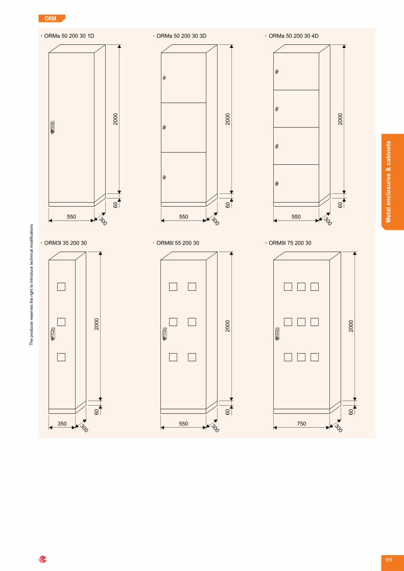
The
prod
ucer
rese
rves
the
right
to in
trodu
ce te
chni
cal m
odifi
catio
ns
Met
al e
nclo
sure
s &
cab
inet
s
99
ORM
•ORMa 50 200 30 1D
60
2000
550 300
•ORM3l 35 200 30
60
2000
350 300
•ORMa 50 200 30 3D
60
2000
550 300
•ORM6l 55 200 30
60
2000
550 300
•ORMa 50 200 30 4D
60
2000
550 300
•ORM9l 75 200 30
60
2000
750 300

The
prod
ucer
rese
rves
the
right
to in
trodu
ce te
chni
cal m
odifi
catio
ns
www.emiter.com
Met
al e
nclo
sure
s &
cab
inet
s
100
ORM
•ORM12l 95 200 30
60
2000
950 300
•ORM15l 115 200 30
60
2000
1150 300
Reference chart
cabinet typedimensions [mm]
no.ofdoors destination
equipment
width(s)
height(w)
depth(g) P1 TM T3f W Pl
ORMa 35 200 30 1D P1 TM 350 2000 300 1 administration x x option option optionORMa 55 200 30 1D P1 TM 550 2000 300 1 administration x x option option optionORMa 35 200 30 3D P1 350 2000 300 3 administration x - - - optionORMa 55 200 30 3D P1 550 2000 300 3 administration x - - - optionORMa 35 200 30 4D P1 350 2000 300 4 administration x - - - optionORMa 55 200 30 4D P1 550 2000 300 4 administration x - - - optionORM3l 35 200 30 T3f TM 350 2000 300 1 counters - x x option optionORM6l 55 200 30 T3f TM 550 2000 300 1 counters - x x option optionORM9l 75 200 30 T3f TM 750 2000 300 1 counters - x x option optionORM12l 95 200 30 T3f TM 950 2000 300 2-wings counters - x x option optionORM15l 115 200 30 T3f TM 1150 2000 300 2-wings counters - x x option option
P1-smoothmountingplateTM-modularkit-DINrail+maskingpanelsmadeofsteelsheetT3f-threephasecounterplateW-sight-glassPl - back plate
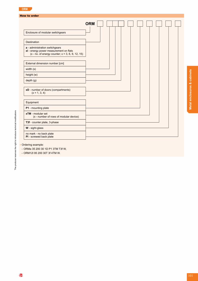
The
prod
ucer
rese
rves
the
right
to in
trodu
ce te
chni
cal m
odifi
catio
ns
Met
al e
nclo
sure
s &
cab
inet
s
101
How to order
ORM
Enclosure of modular switchgears
a
xl
- administration switchgears
- energy power measurement on flats
(x - no. of energy counter; x = 3, 6, 9, 12, 15)
Destination
xD - number of doors (compartments)(x = 1, 3, 4)
width (s)
height (w)
External dimension number [cm]
depth (g)
P1 - mounting plate
xTM - modular set(x - number of rows of modular device)
Equipment
T3f - counter plate, 3-phase
W - sight-glass
no mark - no back plate- screwed back platePl
•Orderingexample: - ORMa 35 200 30 1D P1 3TM T3f W, - ORM12l9520030T3f4TMW.
ORM
ORM_end

The
prod
ucer
rese
rves
the
right
to in
trodu
ce te
chni
cal m
odifi
catio
ns
www.emiter.com
Met
al e
nclo
sure
s &
cab
inet
s
102
Universal enclosures for modular switchgear: wall mounted (ORMU), flush mounted (ORMK)Application
•EnclosuresofmodularswitchgearsaredesignedforbuildingofswitchgearsusingmodulardevicesmountedonDIN-rail.
Type of installation
•ORMUenclosureismountedtothewalldirectlyorusingwallholders;•ORMKenclosureisflushmounted(nestmounted).
Operating conditions
•Lowaggressiveindoorenvironment;•Indoorlocation.
Design
•Carbonsteel,thickness1,5mm,formedbypunchingandbending,joinedbyrivetingandwelding;
•Polyesterstructuralpowderpainted,colourRAL7035;•Nesteddoorssuspendedonconcealedhinges,oneortwolocks,closedbypatentedkey;•Asoptiondoorsequippedwithpolycarbonatewindow;•Cabinetsareequippedwithmodularunit;•ORMUcabinetsareequippedwithsmoothcableglandplate.
Scope of delivery
•Cabinetwithdoorhungonleftorrightedge;•Modularunit;•Smoothcableglandplate.
Accessories
•Doorwithpolycarbonatewindow;•Membraneglandsplate.
Technical data
•Protectionclass:I;•Ingressprotectiondegree:IP30;•Impactprotection:
- IK10:forstandarddoor, - IK05:forwindowdoor.
Dimensions
•ORMU
560 200
w
•ORMK
560 200
w
620
set of modular unit modular unit without masking panels
masking panel
front view (door opened)
DIN rail
ORMU • ORMK
Universal enclosures for modular switchgear: wall mounted (ORMU), flush mounted (ORMK) ORMU_start

The
prod
ucer
rese
rves
the
right
to in
trodu
ce te
chni
cal m
odifi
catio
ns
Met
al e
nclo
sure
s &
cab
inet
s
103
ORMU • ORMK
Reference chart
cabinet type
dimensions [mm] no.ofmodules
in masking panel
no.ofmasking
panelsinthemodular unit
sum of modules in
modular unitwidth(s)
height(w)
depth(g)
ORMU 3 - 72 560 600 200 24 3 72ORMK 3 - 72 560 600 200 24 3 72ORMU 4 - 96 560 750 200 24 4 96ORMK 4 - 96 560 750 200 24 4 96ORMU 5 - 120 560 900 200 24 5 120ORMK 5 - 120 560 900 200 24 5 120ORMU 6 - 144 560 1050 200 24 6 144ORMU 6 - 144 560 1050 200 24 6 144
How to order
ORM
Enclosure of modular switchgear
Number of masking panels in the modular unit
Number of module in masking panels
O - door with window
Membrane gland plate (np.: MC 3, MC 25,MC 35, MC 10-30)
U - wall mountedK - flush mounted
•Orderingexample: - Universalenclosureofmodularswitchgear:ORMU4-96.
ORMU_end

The
prod
ucer
rese
rves
the
right
to in
trodu
ce te
chni
cal m
odifi
catio
ns
www.emiter.com
Met
al e
nclo
sure
s &
cab
inet
s
104
PSBPSA Floor switchgear enclosuresORP
Application
•Indoorenclosureoffloorswitchgearsforenergydistributiontoindividualunitsinablockofflats.
Type of installation
•Free-standingbythewallonthesocle.
Operating conditions
•Indoor;•Dryenvironment.
Design
•Carbonsteel,thickness1,2mm;•Polyesterstructuralpowderpainted,colourRAL7035;•DoorsarelockedbyZ-2106locksorswinghandleRS900lock,theycanbeequippedwithsight-glassesinenergymetercompartments;
•Fieldforterminalstrip;•Twoorfourcounterfieldsenableenergymetermountingwithfuseprotection;•Telecommunicationfields;•Fieldsequippedwithmountingplates.
•Enclosure ORP - 2.3fZ - TWC
264 250100
254
520
520
300
1594
counter fieldwith fuse protection
terminal stripfield
counter fieldwith fuse protection
socle
TV field
•Enclosure ORP - 2.3fZ - TW
264
254
520
520
300
1594
250
Dimension
Floor switchgear enclosures (ORP) ORP_start

The
prod
ucer
rese
rves
the
right
to in
trodu
ce te
chni
cal m
odifi
catio
ns
Met
al e
nclo
sure
s &
cab
inet
s
105
•Enclosure ORP - 2.3fZ - W
264
524
520
300
1344
250
•Enclosure ORP - 3.3f - W
250264
524
520
524
1568
•Enclosure ORP - 2.3fZ - ZITAW
250260300
560
800
400
400
1600
400
400
internetphoneintercom
TV
administra-tion field
fuseprotection
•Enclosure ORP - 3.3f - Z
264
524
520
520
300
1864
250
ORP
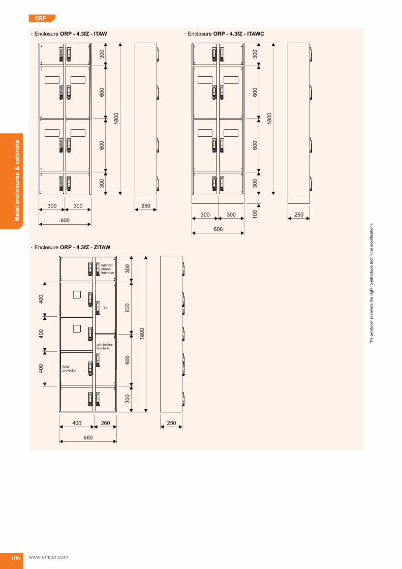
The
prod
ucer
rese
rves
the
right
to in
trodu
ce te
chni
cal m
odifi
catio
ns
www.emiter.com
Met
al e
nclo
sure
s &
cab
inet
s
106
•Enclosure ORP - 4.3fZ - ITAW
300
600
600
300
1800
250300300
600
•Enclosure ORP - 4.3fZ - ZITAW
250260400
660
administra-tion field
fuseprotection
internetphoneintercom
TV
600
600
300
1800
300
400
400
400
•Enclosure ORP - 4.3fZ - ITAWC
250300300
600
300
600
600
300
1800
100
ORP

The
prod
ucer
rese
rves
the
right
to in
trodu
ce te
chni
cal m
odifi
catio
ns
Met
al e
nclo
sure
s &
cab
inet
s
107
ORP
Reference chart
enclosure type
options dimensions [mm]
terminal stripfield
separate fieldofcounter fuses
internet field TVfield administra-
tionfield
sight-glassof counter fields
plinth100 mm
width(s)
height(w)
depth(g)
ORP-2.3fZ-TWORPK-2.3fZ-TW
+ - - T - W C 264 1594 250
ORP-2.3fZ-WORPK-2.3fZ-W
+ - - - - W C 264 1344 250
ORP-2.3f-ZITAWORPK-2.3f-ZITAW
+ Z I T A W C 560 1600 250
ORP-3.3fZ-WORPK-3.3fZ-W
+ - - - - W C 264 1568 250
ORP-3.3f-ZORPK-3.3f-Z
+ - - - - W C 264 1864 250
ORP-4.3fZ-ITAWORPK-4.3fZ-ITAW
+ - I T A W C 520 1640 250
ORP-4.3f-ZITAWORPK-4.3f-ZITAW
+ Z I T A W C 660 1800 250
How to order
ORP
Floor switchgear enclosure
Z - fuse before counter in counter field
Z - separate field of fuse
Number of counter fields x.1f; x.3f, x = 2, 3, 4
- one phase counter plate
-
1f
3f three phase counter plate
I - field of: internet, phone, intercom
-
T - TV field
A - administration field
W - sight-glass of the counter field doors
C - plinth (free standing enclosure)
Additional requirements description
no mark - free standing by the wall- flush mountedK
Design
•Orderingexample: - Floorswitchgearenclosure:ORP-3.3f-Z.
ORP_end
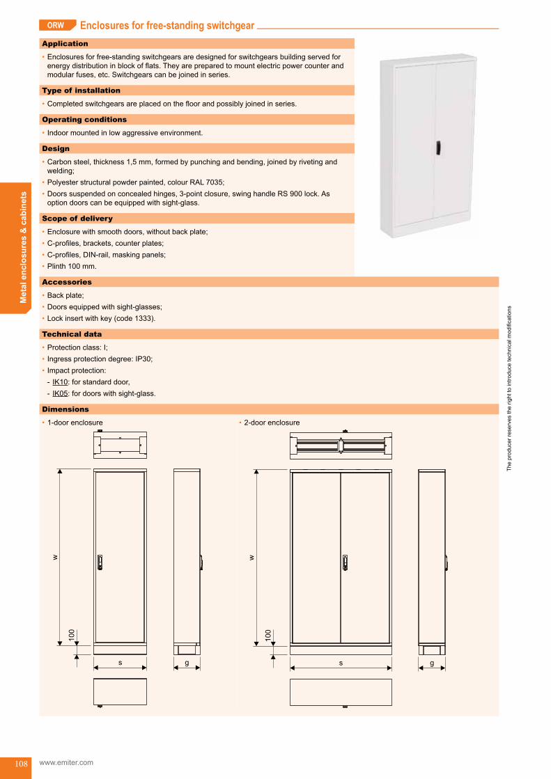
The
prod
ucer
rese
rves
the
right
to in
trodu
ce te
chni
cal m
odifi
catio
ns
www.emiter.com
Met
al e
nclo
sure
s &
cab
inet
s
108
PSBPSA Enclosures for free-standing switchgearORW
Application
•Enclosuresforfree-standingswitchgearsaredesignedforswitchgearsbuildingservedforenergydistributioninblockofflats.Theyarepreparedtomountelectricpowercounterandmodularfuses,etc.Switchgearscanbejoinedinseries.
Type of installation
•Completedswitchgearsareplacedonthefloorandpossiblyjoinedinseries.
Operating conditions
•Indoormountedinlowaggressiveenvironment.
•1-door enclosure
s
100
w
g
•2-door enclosure
s g
100
w
Design
•Carbonsteel,thickness1,5mm,formedbypunchingandbending,joinedbyrivetingandwelding;
•Polyesterstructuralpowderpainted,colourRAL7035;•Doorssuspendedonconcealedhinges,3-pointclosure,swinghandleRS900lock.Asoptiondoorscanbeequippedwithsight-glass.
Scope of delivery
•Enclosurewithsmoothdoors,withoutbackplate;•C-profiles,brackets,counterplates;•C-profiles,DIN-rail,maskingpanels;•Plinth100mm.
Accessories
•Backplate;•Doorsequippedwithsight-glasses;•Lockinsertwithkey(code1333).
Technical data
•Protectionclass:I;•Ingressprotectiondegree:IP30;•Impactprotection:
- IK10:forstandarddoor, - IK05:fordoorswithsight-glass.
Dimensions
Enclosures for free-standing switchgear (ORW) ORW_start
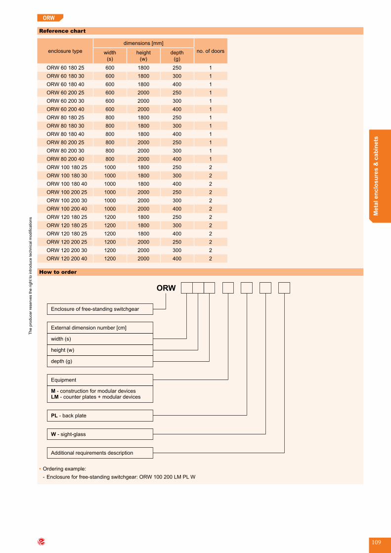
The
prod
ucer
rese
rves
the
right
to in
trodu
ce te
chni
cal m
odifi
catio
ns
Met
al e
nclo
sure
s &
cab
inet
s
109
Reference chart
enclosure typedimensions [mm]
no.ofdoorswidth(s)
height(w)
depth(g)
ORW 60 180 25 600 1800 250 1ORW 60 180 30 600 1800 300 1ORW 60 180 40 600 1800 400 1ORW 60 200 25 600 2000 250 1ORW 60 200 30 600 2000 300 1ORW 60 200 40 600 2000 400 1ORW 80 180 25 800 1800 250 1ORW 80 180 30 800 1800 300 1ORW 80 180 40 800 1800 400 1ORW 80 200 25 800 2000 250 1ORW 80 200 30 800 2000 300 1ORW 80 200 40 800 2000 400 1ORW 100 180 25 1000 1800 250 2ORW 100 180 30 1000 1800 300 2ORW 100 180 40 1000 1800 400 2ORW 100 200 25 1000 2000 250 2ORW 100 200 30 1000 2000 300 2ORW 100 200 40 1000 2000 400 2ORW 120 180 25 1200 1800 250 2ORW 120 180 25 1200 1800 300 2ORW 120 180 25 1200 1800 400 2ORW 120 200 25 1200 2000 250 2ORW 120 200 30 1200 2000 300 2ORW 120 200 40 1200 2000 400 2
How to order
ORW
Enclosure of free-standing switchgear
width (s)
height (w)
External dimension number [cm]
depth (g)
M
LM
- construction for modular devices- counter plates + modular devices
Equipment
PL - back plate
W - sight-glass
Additional requirements description
•Orderingexample: - Enclosureforfree-standingswitchgear:ORW100200LMPLW
ORW

The
prod
ucer
rese
rves
the
right
to in
trodu
ce te
chni
cal m
odifi
catio
ns
www.emiter.com
Met
al e
nclo
sure
s &
cab
inet
s
110
ORW
CONFIGURATION OF BASE EQUIPMENT
Application
•Equipmentformountingelectricenergycounterandbeforeandaftercounterfuseprotection.
Design
•Counterplatesaremountedonhorizontalbrackets.Numberofcounterplatesinenclosurewithcertaindimensionsareshowninthetablebelow.
Reference chart
width[mm]
600 800 1000 1200
height[m
m]
1800
2000
Application
•ItservestocoverbackpartofORWenclosures.
Design
•Carbonsteel,thickness1,2mm;•Polyesterstructuralpowderpainted,colourRAL7035;•Mountingtotheenclosureusingself-tappingscrews.
Counter plates + masking panels - LM
Back plate - PL
Configuration of base equipment

The
prod
ucer
rese
rves
the
right
to in
trodu
ce te
chni
cal m
odifi
catio
ns
Met
al e
nclo
sure
s &
cab
inet
s
111
Reference chart
enclosure type back plate type dimensions [mm]width×height
ORW60180... PL 60 180 600×1800ORW60200... PL 60 200 600×2000ORW80180... PL 80 180 800×1800ORW80200... PL 80 200 800×2000ORW100180... PL 100 180 1000×1800ORW100200... PL 100 200 1000×2000ORW120180... PL 120 100 1200×1800ORW120200... PL 120 200 1200×2000
Application
•Mountedinthedoorsofcounterfields.
Design
•InjectedPC;•Mounting:tothedoorsheetusingsnaplock.
ORW
Sight-glass - WE
Dimensions
102,5
11
8
10
2,5
6
107
Reference chart
type art.no.
WE 107 907 1011
ORW_end

The
prod
ucer
rese
rves
the
right
to in
trodu
ce te
chni
cal m
odifi
catio
ns
www.emiter.com
Met
al e
nclo
sure
s &
cab
inet
s
112
PSBPSA Enclosure for pole transformer station switchgearST/A
Application
•Poletransformerstationswitchgear.
Type of installation
•Enclosureisdesignedformountingtoapoleusingtwoclampingringswithdiameter350and370mm,orontheplatformfixedtothepole.
Operating conditions
•Industrialenvironment.
Design
•Aluminiumsheet,thickness2mm,formedbypunchingandbending;•Partsarejoinedbyrivetingandwelding;•Polyesterstructuralpowderpainted,colourRAL7035;•Theroofisequippedwithinlet/outletpipeswhichenabletoenteroffeedingcablesandexitofoutflowcablestothetop,tooverheadlineandstreetlighting;
•Thebottomofenclosurecanbeequippedwithflatcoverorcoverwithpipeswhichenableexitofoutflowcablestotheearth;
•Theenclosurecanbeequippedwithcablechannel,coveredoutflowcablesgoingtotheearth;
•Doorshave3-pointclosuresystem.Itispossibletoapplypadlock;•Enclosurehasinnerframetowhicharemountedbusbarbrackets,mountingplateofmeasu-ringfieldandotherequipment.
•Mountingplateofmeasuringfieldissuspendedonthehinges;•Thedoorfrommeasuringfieldsidehasfoldingshelfforlaptop.
Technical data
•Protectionclass:I;•Ingressprotectiondegree:IP44;•Impactprotection:IK10.
Dimensions
Technical data of switchgear in ST/A enclosures
rated operational voltage - Un 230 V / 400 Vrated insulation voltage - Ui 500 Vrated frequency 50 Hzratedimpulsewithstandvoltage 8kV(1,2/50μs)rated current - In 1250 Arated current of load circuits up to 630 Aratedshort-timewithstandcurrent-Icw 20kA:1s-mainbusbar/12kA:1s-busbarN,PEratedpeakwithstandcurrent-Ipk 40 kA - main busbar / 25 kA - busbar N, PEcrosssectionofoutflowcables 50 - 240 mm2
ingress protection degree IP44impact protection IK10protection class Iway of installation onthepole
Enclosure for pole transformer station switchgear (ST/A)ST/A_start
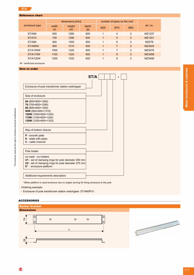
The
prod
ucer
rese
rves
the
right
to in
trodu
ce te
chni
cal m
odifi
catio
ns
Met
al e
nclo
sure
s &
cab
inet
s
113
Reference chart
enclosure typedimensions [mm] numberofpipesontheroof
art.no.width(s)
height(w)
depth(g) Ø25 Ø70 Ø80
ST/A60 600 1280 600 1 4 2 MZ1237ST/A70 700 1290 600 1 5 2 MZ1251ST/A80 800 1300 600 1 6 2 MZ276ST/A90W 900 1310 600 1 7 2 MZ3024ST/A100W 1000 1320 600 1 7 2 MZ3076ST/A110W 1100 1324 600 1 8 2 MZ3488ST/A120W 1200 1333 600 1 9 2 MZ3489
W - reinforced enclosure
How to order
ST/A
Enclosure of pole transformer station switchgear
Size of enclosure
60
70
8
(600 1280)
(700 600 1290)
×600×
× ×
× ×
× ×
× ×
0
90W
100W
110W
120W
(800 600 1300)
(900 600 1310)
(1000 600 1320)
( )
( )
1100 600 1324
1200 600 1333
× ×
× ×
Way of bottom closure
P
K
C
- smooth plate
- plate with pipes
- cable channel
Pole holder
-
Additional requirements description
no mark - no holders
- set of clamping rings for pole diameter
-
U1
U2
350 mm
*
set of clamping rings for pole diameter 73 0 mm
D - enclosure platform
* When platform is used enclosure has no angles serving for fixing enclosure to the pole
•Orderingexample: - Enclosureofpoletransformerstationswitchgear:ST/A60PU1.
ST/A
Dimensions
L
74
28
ACCESSORIES
Busbar bracket
Accessories

The
prod
ucer
rese
rves
the
right
to in
trodu
ce te
chni
cal m
odifi
catio
ns
www.emiter.com
Met
al e
nclo
sure
s &
cab
inet
s
114
Dimensions
L
74
28
74,3
M10
Dimensions
A
100 100 100 100 30
B×M12
2×Ø12,5
Reference chart
name
dimensions [mm]
widthoftheST/Aenclosure
(s)
spacing of mountingholes
(L)
art.no.
busbar bracket
600 552 M1252700 652 M1253800 752 M420900 852 M12541000 952 M12551100 1052 M39851200 1152 M3986
ST/A
Busbar bracket with insulators h = 50
Reference chart
name
dimensions [mm]
widthoftheST/Aenclosure
(s)
spacing of mountingholes
(L)
art.no.
busbarbracketwithinsulatorsh=50
600 552 M1256700 652 M1257800 752 M606900 852 M12581000 952 M12591100 1052 M39871200 1152 M3988 Number of pieces for enclosure: 4
Number of pieces for enclosure: 4
Phase busbars (L1, L2, L3)
Reference chart
name
dimensions [mm]
widthoftheST/Aenclosure
(s)
lengthofthe busbar
(A)
numberofpushin nuts
(B)
art.no.
phasebusbar (L1, L2, L3)
600 460 5 M3565700 560 6 M3566800 660 7 M3567900 760 8 M3568
1000 860 9 M35691100 960 10 M39891200 1060 11 M3990
•cross-section:40×5mm•material:Cu
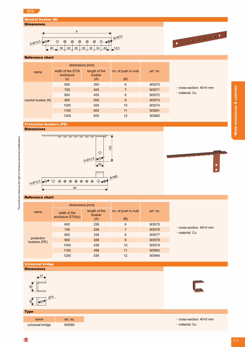
The
prod
ucer
rese
rves
the
right
to in
trodu
ce te
chni
cal m
odifi
catio
ns
Met
al e
nclo
sure
s &
cab
inet
s
115
ST/A
Dimensions
A
40 12,5
3× 12,5Ø
B×M10
34383838383860
Dimensions
3× 12,5Ø
B×M8
2× 12,5Ø
40
60
13
5
Dimensions
Ø10
50
47
40
Neutral busbar (N)
Reference chart
name
dimensions [mm]
widthoftheST/Aenclosure
(s)
lengthofthebusbar
(A)
no.ofpushinnuts
(B)
art.no.
neutral busbar (N)
600 355 6 M3570700 405 7 M3571800 455 8 M3572900 505 9 M3573
1000 555 10 M35741100 605 11 M39911200 655 12 M3992
•cross-section:40×5mm•material:Cu
Protection busbars (PE)
Reference chart
name
dimensions [mm]
widthoftheenclosure ST/A(s)
lengthofthebusbar
(A)
no.ofpushinnuts
(B)
art.no.
protection busbars (PE)
600 238 6 M3575700 288 7 M3576800 338 8 M3577900 388 9 M3578
1000 438 10 M35791100 488 11 M39931200 538 12 M3994
•cross-section:40×5mm•material:Cu
Universal bridge
Type
name art.no.
universal bridge M3580
•cross-section:40×5mm•material:Cu

The
prod
ucer
rese
rves
the
right
to in
trodu
ce te
chni
cal m
odifi
catio
ns
www.emiter.com
Met
al e
nclo
sure
s &
cab
inet
s
116
Dimensions
s
w
hinge
Dimensions
N
PE45
Busbar unit (N+PE)
Reference chart
namewidthoftheST/A
enclosure(s) [mm]
art.no.
busbar unit (N+PE)
600 MZ3580700 MZ3581800 MZ3582900 MZ35831000 MZ35841100 MZ39951200 MZ3996
•crosssection:40×5mm•material:Cu
Tilting mounting plate (upper)
Reference chart
name
dimensions [mm]
art.no.widthoftheST/Aenclosure
(s)
dimensions of mounting plate
(s×w)
tilting mounting plate
600 510×515 MZ2775700 610×515 MZ2776800 710×515 MZ2777900 810×515 MZ2778
1000 910×515 MZ27791100 910×515 MZ27791200 910×515 MZ2779
ST/A

The
prod
ucer
rese
rves
the
right
to in
trodu
ce te
chni
cal m
odifi
catio
ns
Met
al e
nclo
sure
s &
cab
inet
s
117
ST/A
Lower coversReference chart
type description view art.no.
P lowercoverwithoutpipes M596
K1 lowercoverwithonepipe MZ2196
K4 lowercoverwithfourpipes MZ278
K6 lowercoverwithsixpipes MZ937
Dimensions
s
w23
plate frame
Stable mounting plate (lower)
Reference chart
name
dimensions [mm]
art.no.widthoftheST/Aenclosure
(s)
dimensions of mounting plate
(s×w)
mountingplatewithframe
600 560×515 M1260700 660×515 M1261800 760×515 M516900 860×515 M12621000 960×515 M12631100 960×515 M12631200 960×515 M1263 Number of pieces for enclosure: 2
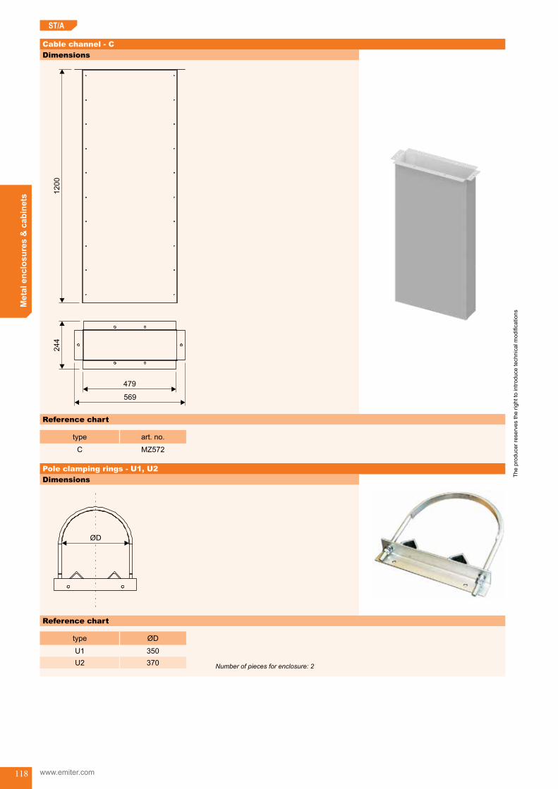
The
prod
ucer
rese
rves
the
right
to in
trodu
ce te
chni
cal m
odifi
catio
ns
www.emiter.com
Met
al e
nclo
sure
s &
cab
inet
s
118
ST/A
Dimensions
Dimensions1200
479
569
244
Reference chart
type art.no.
C MZ572
Cable channel - C
Pole clamping rings - U1, U2
Reference chart
type ØD
U1 350U2 370 Number of pieces for enclosure: 2

The
prod
ucer
rese
rves
the
right
to in
trodu
ce te
chni
cal m
odifi
catio
ns
Met
al e
nclo
sure
s &
cab
inet
s
119
ST/A
ST/A enclosure platform - type PD-STApplication
•DesignedforcarryingofST/Aenclosureincaseofmountingheavydisconnectorswhichcancauseoverloadinganddeformingoftheenclosure.Itisusedasalternativefordirectmountingonthepole.
Type of installation
•Platformismountedusingtwoclampingringstothepoleandenclosureissetupandfixedtotheplatform.
Design
•Platformisweldedfromsteelangleswithdimension40×40×4mmandhot-dipzincplated;•Sideangleswithdimension50×50×5mmhaveholesformountingonpoleclampingrings;•Upperframeofplatformhasholesformountingenclosure(holesinenclosuremustbedrilled).
Reference chart
type destined for enclosure
PD-ST8ST/A60ST/A70ST/A80ST/A90
PD-ST10ST/A100ST/A110ST/A120
How to order
•ST/Aenclosureplatform:PD-ST8.
Scope of delivery
•Platformisdeliveredwithsetofboltsandscrews.(Theboltsformountingplatformtothepolearecompletedinthepoleclampingrings).
Dimensions
•PD-ST8 •PD-ST10
ST/A_end

The
prod
ucer
rese
rves
the
right
to in
trodu
ce te
chni
cal m
odifi
catio
ns
www.emiter.com
Met
al e
nclo
sure
s &
cab
inet
s
120
Enclosure for pole transformer station switchgear RSO
Application
•Switchgearsforpoletransformerstation.
Type of installation
•Enclosureisdesignedtobemountedontheplatform.
Operating conditions
•Outdoormountedinindustrialenvironment.
Design
•Aluzincplatedsteel,thickness1,5mm,formedbypunchingandbending;•Sheetelementsarejoinedusingscrewsandrivets;•IntheroofarepipeswithØ95mmandØ75mm.Theyareclosedwithremovablecovers.Pipesenabletoenterandexitcablesforfeedingandoutflowofcircuitsandstreetlighting;
•OnthebottomthereareholesØ97mm(closedbycovers)forexitdownofoutflowcables;•Enclosureisequippedtwotwo-wingsdoors,with3-pointclosure,lockswithDtypekey;•EnclosureisequippedwithinnermountingC-profiles.
Technical data
•Protectionclass:I;•Ingressprotectiondegree:IP43;•Impactprotection:IK10.
Dimensions
•Enclosurewithflatroof(RSO10110276)
g
995
w1
w
s
3×Ø75
160 150
300
72
250 170 1× 9Ø 5
view from the bottom
5×97
Ø
Enclosure for pole transformer station switchgear (RSO) RSO_start

The
prod
ucer
rese
rves
the
right
to in
trodu
ce te
chni
cal m
odifi
catio
ns
Met
al e
nclo
sure
s &
cab
inet
s
121
RSO
•Enclosurewithapexroof(RSO10112676,RSO10111876)
s
105 160
5×Ø75
100
170
264
264
528
view fromthe bottom
g1100
w1
w
72
1× 9Ø 5 320
8×97
Ø
•Enclosurewithapexroof(RSO12815086)
s g
1330
w1
w
72
view fromthe bottom
200
100
264
160 150
320238 160
2× 9Ø 5
4× 7Ø 5
9×97
Ø
Reference chart
enclosure typedimensions [mm]
roof typewidth(s)
height(w) (w1)
depth(g)
RSO 101 102 76 1010 1020 25 760 flatRSO 101 126 76 1010 1260 160 760 apexRSO 101 11876 1010 1180 80 760 apexRSO 128 150 86 1280 1500 168 860 apex

The
prod
ucer
rese
rves
the
right
to in
trodu
ce te
chni
cal m
odifi
catio
ns
www.emiter.com
Met
al e
nclo
sure
s &
cab
inet
s
122
RSO
How to order
•Enclosureofpoletransformerstationswitchgear:RSO10111876.
ACCESSORIES
Reference chart
type art.no.
coverØ75opened NMZ 1462coverØ95opened NMZ 1463coverØ75blind NMZ 1464coverØ95blind NMZ 1465
Lower cover with one pipe
Accessories
RSO_end

The
prod
ucer
rese
rves
the
right
to in
trodu
ce te
chni
cal m
odifi
catio
ns
Met
al e
nclo
sure
s &
cab
inet
s
123
NTw Enclosure for internal transformer station switchgearDesign
•Enclosureismadeofaluzincplatedsteel;•Sheetelementsarejoinedusingscrewsandrivets.
Design
400
1125 (
1250, 1325 -
options)
(2055)
680
250
n + 60
600foot for foundation
enclosure on channel
CO
supply - outflowpanel CZO
enclosure ofmeasuring
panelOPP10OPP12
630430 (for OPP10)
630 (for OPP12)
312 (for ZG/OD; ZD/OG)
400 (for ZG/OG)
enclosure ofsupply panelOPZp (right),OPZl (left)
busbarcover
Technical data of switchgear in NTw enclosures
rated operational voltage - Un 230 V / 400 Vrated insulation voltage - Ui 690 Vrated frequency 50 Hzratedimpulsewithstandvoltage 8kV(1,2/50μs)rated current - In 1600 Aratedshort-timewithstandcurrent-Icw 25kA:1s-mainbusbar/15kA:1s-busbarN,PEratedpeakwithstandcurrent-Ipk 63 kA - main busbar / 37,5 kA - busbar N, PEcrosssectionofoutflowcables 50 - 240 mm2
ingress protection degree IP20 / IP4Ximpact protection IK10protection class Iway of installation directlyoncablechanneloronfoots
Description of the particular segments of the NTw enclosure
•Supply-outflowpanel-CZOEquipment: - twoorthreeverticalperforatedprofilesforinsulatorsmountingforhorizontalbusbars, - onthebottomdoorsareclosedbylocks.ItcoverstheplaceofcableconnectiontodisconnectorsandPE+Nbusbars, - doorsaresupportedonthetopbyremovablecross-bar.
Dimensions: - width:n+60mm;(n-numberofdisconnector,width100mmn=5,…16), - height:1250mm, - depth:310mmor400mm.
•Enclosure of supply panel - OPZ - rightsideofCZOmounted-OPZp, - leftsideofCZOmounted-OPZl.
Enclosure for internal transformer station switchgear (NTw)NTw_start
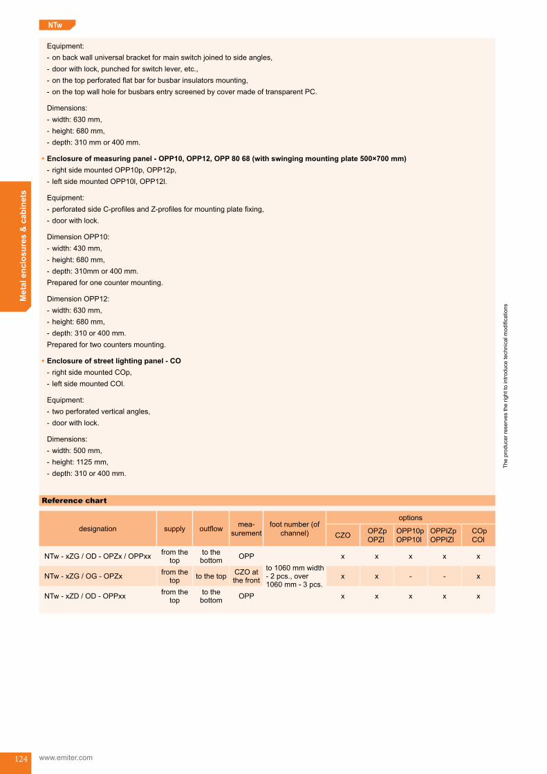
The
prod
ucer
rese
rves
the
right
to in
trodu
ce te
chni
cal m
odifi
catio
ns
www.emiter.com
Met
al e
nclo
sure
s &
cab
inet
s
124
NTw
Equipment: - onbackwalluniversalbracketformainswitchjoinedtosideangles, - doorwithlock,punchedforswitchlever,etc., - onthetopperforatedflatbarforbusbarinsulatorsmounting, - onthetopwallholeforbusbarsentryscreenedbycovermadeoftransparentPC.
Dimensions: - width:630mm, - height:680mm, - depth:310mmor400mm.
•Enclosureofmeasuringpanel-OPP10,OPP12,OPP8068(withswingingmountingplate500×700mm) - rightsidemountedOPP10p,OPP12p, - leftsidemountedOPP10l,OPP12l.
Equipment: - perforatedsideC-profilesandZ-profilesformountingplatefixing, - doorwithlock.
DimensionOPP10: - width:430mm, - height:680mm, - depth:310mmor400mm.Preparedforonecountermounting.
DimensionOPP12: - width:630mm, - height:680mm, - depth:310or400mm.Preparedfortwocountersmounting.
•Enclosure of street lighting panel - CO - rightsidemountedCOp, - leftsidemountedCOl.
Equipment: - two perforated vertical angles, - doorwithlock.
Dimensions: - width:500mm, - height:1125mm, - depth:310or400mm.
Reference chart
designation supply outflow mea-surement
foot number (of channel)
options
CZO OPZpOPZl
OPP10pOPP10l
OPPIZpOPPIZl
COpCOl
NTw - xZG / OD - OPZx / OPPxx fromthetop
tothebottom OPP
to1060mmwidth-2pcs.,over1060mm-3pcs.
x x x x x
NTw - xZG / OG - OPZx fromthetop tothetop CZO at
thefront x x - - x
NTw - xZD / OD - OPPxx fromthetop
tothebottom OPP x x x x x
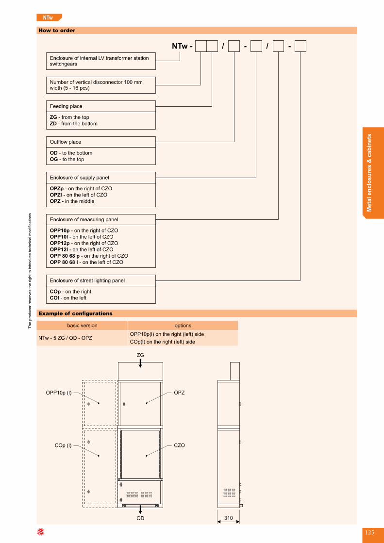
The
prod
ucer
rese
rves
the
right
to in
trodu
ce te
chni
cal m
odifi
catio
ns
Met
al e
nclo
sure
s &
cab
inet
s
125
How to order
NTw -
Enclosure of internal LV transformer stationswitchgears
Feeding place
ZG
ZD
- from the top
- from the bottom
Enclosure of supply panel
OPZp
OPZl
OPZ
- on the right of CZO
-
- in the middle
on the left of CZO
Enclosure of measuring panel
-
OPP10p
OPP10l
OPP12p
OPP12l
- on the right of CZO
-
-
-
on the left of CZO
CZO
CZO
- CZO
- CZO
OPP 80 68 p
OPP 80 68 l
on the right of
on the left of
on the right of
on the left of
-
Number of vertical disconnector 100 mmwidth (5 - 16 pcs)
Outflow place
OD
OG
- to the bottom
- to the top
Enclosure of street lighting panel
COp
COl
- on the right
- on the left
Example of configurations
basic version options
NTw - 5 ZG / OD - OPZOPP10p(l)ontheright(left)sideCOp(l)ontheright(left)side
CZO
310
OPZ
COp (l)
OPP10p (l)
OD
ZG
NTw
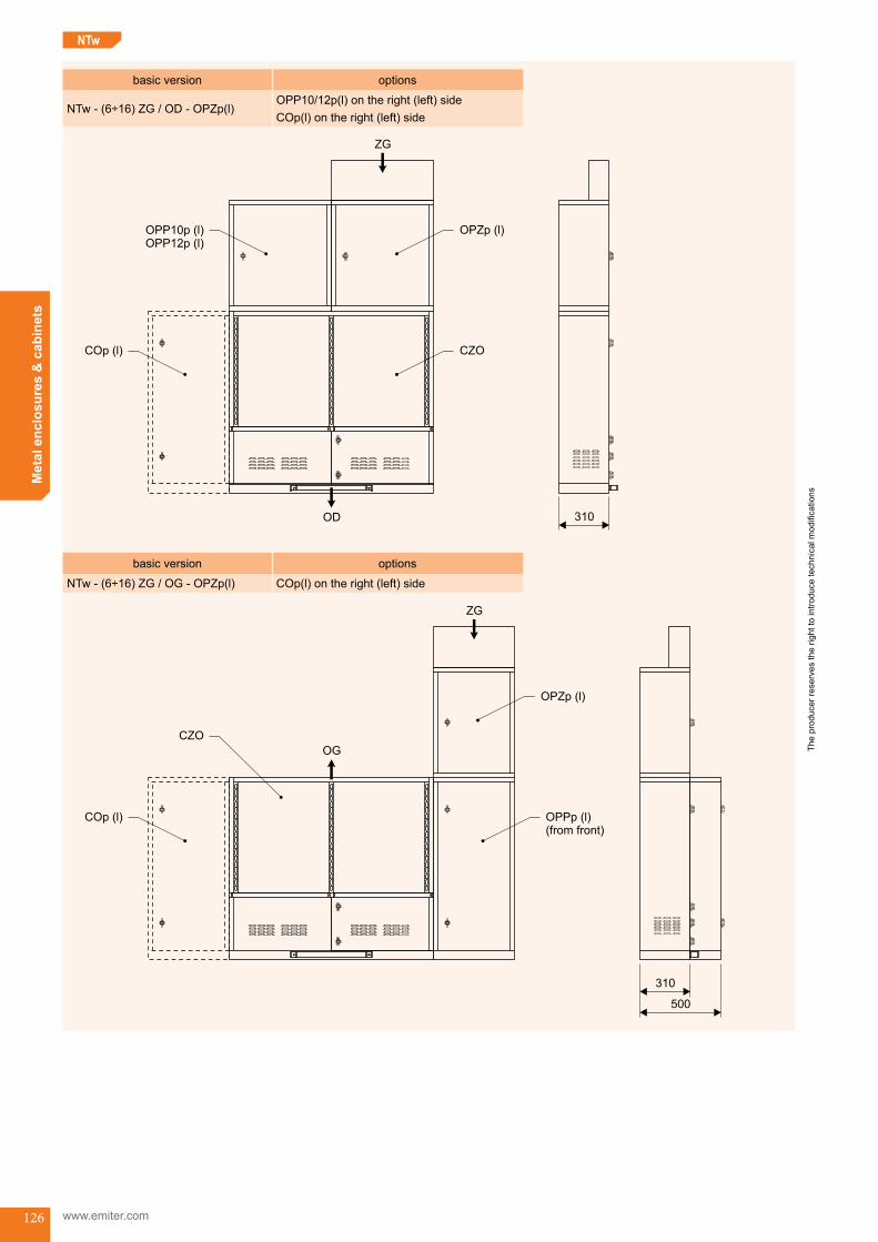
The
prod
ucer
rese
rves
the
right
to in
trodu
ce te
chni
cal m
odifi
catio
ns
www.emiter.com
Met
al e
nclo
sure
s &
cab
inet
s
126
basic version options
NTw - (6÷16) ZG / OD - OPZp(l)OPP10/12p(l)ontheright(left)sideCOp(l)ontheright(left)side
CZO
310
OPZp (l)
COp (l)
OPP10p (l)OPP12p (l)
ZG
OD
basic version options
NTw - (6÷16) ZG / OG - OPZp(l) COp(l)ontheright(left)side
OPPp (l)(from front)
COp (l)
CZO
OPZp (l)
OG
ZG
310
500
NTw

The
prod
ucer
rese
rves
the
right
to in
trodu
ce te
chni
cal m
odifi
catio
ns
Met
al e
nclo
sure
s &
cab
inet
s
127
basic version options
NTw - (6÷16) ZD / OG - OPZp(l)OPPIO/12p(l)ontheright(left)sideCOp(l)ontheright(left)side
OPZp (l)COp (l)
CZO
OPP10p (l)OPP12p (l)OPP 80 68 p (l)
OG
500ZD
NTw
NTw_end

The
prod
ucer
rese
rves
the
right
to in
trodu
ce te
chni
cal m
odifi
catio
ns
www.emiter.com
Met
al e
nclo
sure
s &
cab
inet
s
128
RSOPSBPSA Enclosure for construction site switchgearORB
Application
•Theenclosureissuitableforhousingconstructionsiteswitchgears,aswellasthesupplyoftemporaryelectricinstallationsforentertainment,tourist,tradeeventsandindustry.
Type of installation
•Enclosureisstandingonthegroundofconstructionsite.
Operating conditions
•Atmosphericconditionsinindustrialenvironment.
Design
•Aluzincplatedsteel,thickness1,5mmformedbypunchingandbending;•Polyesterstructuralpowderpainted,colourRAL7035;•Paintedelementsarejoinedusingscrewsandrivets;•Nesteddoorsaresuspendedonconcealedhinges,swinghandleRS900lock,camandroundbars.
Design of the stand
•Aluzincplatedsteel,thickness2mm,formedbypunchingandbending;•Polyesterstructuralpowderpainted,colourRal7035;•Elementsarejoinedusingscrewsandrivets.
Enclosure equipment
•Mountingplate;•Standwithhandlesservestotransferswitchgearfromplacetoplace.
Technical data
•Protectionclass:I;•Ingressprotectiondegree:IP43;•Impactprotection:IK10.
Dimensions
550 600
300
w700
Reference chart
typedimensions [mm]
width(s)
height(w)
depth(g)
ORB 55 60 30 550 600 300ORB 55 80 30 550 800 300
Enclosure for construction site switchgears (ORB) ORB_start
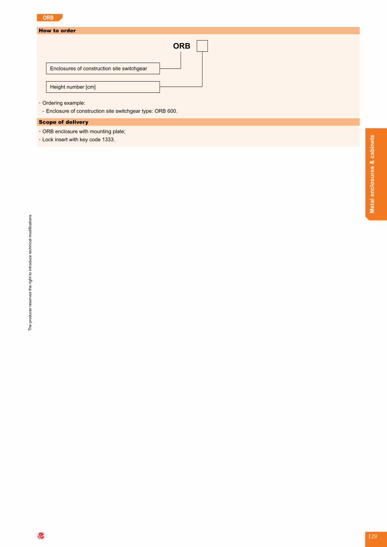
The
prod
ucer
rese
rves
the
right
to in
trodu
ce te
chni
cal m
odifi
catio
ns
Met
al e
nclo
sure
s &
cab
inet
s
129
ORB
How to order
ORB
Height number [cm]
Enclosures of construction site switchgear
•Orderingexample: - Enclosureofconstructionsiteswitchgeartype:ORB600.
Scope of delivery
•ORBenclosurewithmountingplate;•Lockinsertwithkeycode1333.
obu-endORB_end


Universal equipment
wyp-start

132
The
prod
ucer
rese
rves
the
right
to in
trodu
ce te
chni
cal m
odifi
catio
ns
www.emiter.com
Uni
vers
al e
quip
men
t
type art.no.
KL 27 923 2708KL 30 923 3012KL 60 923 6012KL 165 M595
OZB • OZC
KL
Busbar masking panels
Distance pins
KL 60
Ø2
0
50
60
KL 30
Ø2
0
20
30
KL 27
M8
17
27
KL 165
165
150
M1
2
Ø1
5
Ø1
5
M1
2
M1
2
>TP (PC)<
•Side panels •Central panels
type art.no.
OZB 25 920 2570OZB 45 920 4570OZB 85 920 8570OZC 50 920 5070OZB 100 920 9070
Each pin has a screw
>TP (PP 6)<
-Material:transparent polycarbonate
-Thickness:3 mm
-Material:polypropylene
OZB 25
700
25
OZB 45
700
45
OZB 85
700
85
OZC 50
700
50
OZC 100
700
100
Busbar masking panels (OZB, OZC)Distance pins (KL)

133
The
prod
ucer
rese
rves
the
right
to in
trodu
ce te
chni
cal m
odifi
catio
ns
Uni
vers
al e
quip
men
t
V - Volume (ml)
NKK
LRS
Cage nuts
Lacquer for the renovation of metal cabinets standard colour RAL 7035
Sight glasses
D
W 89
WS 95
WS 195
WE 107
Ø2
,5
7
Ø9
3
Ø1
22
Ø1
02
107
11
8
10
2,5
102,5
69
5
195
89
189
95
958
989 3
3
type D art.no.
NKK 6 M6 923 2708NKK 8 M8 923 3012
W • WE • WS
type art.no.
W 89 907 0006WE 107 907 1011WS 95 907 0909WS 195 907 1919
type V art.no.
LRS 400 400 931 0001
>TP (PC)<
-Material:transparent polycarbonate
-Material:steel zinc plated
Cage nuts (NKK)Sight glasses (W, WE, WS)Lacquer for the renovation of metal cabinets standard colour RAL 7035 (LRS)

134
The
prod
ucer
rese
rves
the
right
to in
trodu
ce te
chni
cal m
odifi
catio
ns
www.emiter.com
Uni
vers
al e
quip
men
t
WRS • WRH
RS • RW • ED • CZ • M • PM • Z
Lock inserts
Counter plates
Locks
type art.no.
RS 400 905 0001RS 400U 905 0002RS 420 905 0003RS 420U 905 0004RS 900 905 0008-RAL9005ED 125 905 0006RW 300 905 0005CZ1-E1 905 0007M22 905 0008M22W 905 0009PM 905 0010Z-0233 905 0011Z-2106 905 0012
RS 400
CZ1-E1
RS 400U
M22
RS 420U
PM
RW 300
Z-0233
ED 125RS 900
Z-2106
RS 420
M22W
WRS-K WRS-T6 WRS-T9 WRS-KW8
WRS-S WRS-C9 WRS-D5 WRS-N
WRS-L WRH-T WRH-KW6 WRS-T11
type art.no.
WRS-K 918 0001WRS-T6 918 0002WRS-T9 918 0003WRS-KW8 918 0004WRS-S 918 0005WRS-C9 918 0006WRS-D5 918 0007WRS-N 918 0008WRS-L 918 0009WRH-T 918 0010WRH-KW6 918 0011WRS-T11 918 0012
>TP (PA 6)<
T • TLE
155
24
0
50
110
14
0
T-1F
12
T-3F
35
0
197
94
48
12
01
56
12
T - FLE 3
180
119
31
0
74
13
912
type art.no.
T-3F 929 7001T-1F 929 7002TLE-3F 930 7002
>TP (ABS)<
-Material:ABS
Locks (RS, RW, ED, CZ, M, PM, Z)Lock inserts (WRS, WRH)Counter plates (T, TLE) zamki

135
The
prod
ucer
rese
rves
the
right
to in
trodu
ce te
chni
cal m
odifi
catio
ns
Uni
vers
al e
quip
men
t
Pocket for documents
KD-A6
KD-A4
21
9
230
23
6
262self-adhesive tape
16
1
121
17
0
140
24
32
D
C
E
A
B
D
A
B
E
D HH
type UN (AC/DC) A B C D E art.no.
D625 400 / 500 25 7 16 M6 21 929 7003D630 600 / 750 30 7 25 M6 31 929 7008D830 600 / 750 30 9 26 M8 33 929 7004D835 600 / 750 35 9 28 M8 32 929 7005D1035 600 / 750 35 9 26 M10 32 929 7009D840 1000 / 1200 40 12 31 M8 39 929 7006D1040 1000 / 1200 40 12 31 M10 39 929 7010D1045 1000 / 1200 45 12 32 M10 41 929 7011D1050 1200 / 1500 50 17 36 M10 48 929 7012D1250 1200 / 1500 50 17 36 M12 48 929 7013D851E 1000 / 1200 51 17 27 M8 35 929 7007D1260 1500 / 1800 60 17 38 M12 52 929 7014D1065 1500 / 1800 65 22 41 M10 55 929 7015D1265 1500 / 1800 65 22 41 M12 55 929 701635HH830 600 / 750 30 9 - M8 35 929 7017
KD
D • HH
>TP (PA 6)<
type art.no.
KD-A6 919 1417KD-A4 919 2624
Insulators
>DP (UP+GF)<
Un - rated voltage
-Material:glass-fibrereinforcedpolyester
-Material:polyamide
Insulators (D, HH)Pocket for documents (KD)
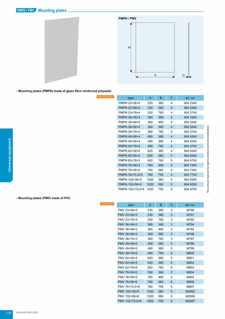
136
The
prod
ucer
rese
rves
the
right
to in
trodu
ce te
chni
cal m
odifi
catio
ns
www.emiter.com
Uni
vers
al e
quip
men
tPMPN • PMV Mounting plates
B
A C
type A B C art.no.
PMPN 23×36×4 230 360 4 904 2340PMPN 23×56×4 230 560 4 904 2540PMPN 23×76×4 230 760 4 904 2740PMPN 36×36×4 360 360 4 904 3340PMPN 36×46×4 360 460 4 904 3440PMPN 36×56×4 360 560 4 904 3540PMPN 36×76×4 360 760 4 904 3740PMPN 49×36×4 490 360 4 904 4340PMPN 49×56×4 490 560 4 904 4540PMPN 49×76×4 490 760 4 904 4740PMPN 62×36×4 620 360 4 904 6340PMPN 62×56×4 620 560 4 904 6540PMPN 62×76×5 620 760 5 904 6750PMPN 76×46×4 760 460 4 904 7440PMPN 76×56×4 760 560 4 904 7540PMPN 76×75,5×5 760 755 5 904 7750PMPN 102×36×5 1020 360 5 904 9350PMPN 102×56×5 1020 560 5 904 9550PMPN 102×75,5×5 1020 755 5 904 9750
type A B C art.no.
PMV 23×36×3 230 360 3 M790PMV 23×56×3 230 560 3 M791PMV 23×76×3 230 760 3 M792PMV 36×36×3 360 360 3 M794PMV 36×46×3 360 460 3 M795PMV 36×56×3 360 560 3 M796PMV 36×76×3 360 760 3 M797PMV 49×36×5 490 360 5 M798PMV 49×56×5 490 560 5 M799PMV 49×76×6 490 760 6 M800PMV 62×36×5 620 360 5 M801PMV 62×56×5 620 560 5 M802PMV 62×76×6 620 760 6 M803PMV 76×36×5 760 360 5 M804PMV 76×46×5 760 460 5 M805PMV 76×56×6 760 560 6 M806PMV 76×75,5×6 760 755 6 M807PMV 102×36×6 1020 360 6 M2855PMV 102×56×6 1020 560 6 M2856PMV 102×75,5×6 1020 755 6 M2857
>DP (UP+GF)<
>TP (PVC)<
•Mountingplates(PMPN)madeofglassfibrereinforcedpolyester
•Mountingplates(PMV)madeofPVC
PMPN / PMV
Mounting plates (PMPN, PMV)

137
The
prod
ucer
rese
rves
the
right
to in
trodu
ce te
chni
cal m
odifi
catio
ns
Uni
vers
al e
quip
men
t
d
c
a
b
f
e
g
type d a b c e f g
NZU-6 M6 20 36 20 8,5 8 36NZU-8 M8 20 36 20 8,5 8 36NZU-10 M10 25 45 25 10 10 45NZU-12 M12 30 54 30 11 12 53NZU-14 M14 30 54 30 11 12 53NZU-16 M16 35 63 35 13 14 62
• Permissible load
•Application
•Howtoorder - Lifting ring NZU-12
NZU
Lifting ringsNZU
F
F F
d[mm]
permissibleload(45°)[kg]
M6 60,0M8 95,0M10 170,0M12 240,0M14 350,0M16 500,0
enclosure type application
OWW NZU-10SR NZU-10
NTw NZU-12
d[mm]
permissibleload(90°)[kg]
M6 90,0M8 140,0M10 230,0M12 340,0M14 500,0M16 700,0
-Material:steel zinc plated
Lifting rings (NZU)

138
The
prod
ucer
rese
rves
the
right
to in
trodu
ce te
chni
cal m
odifi
catio
ns
www.emiter.com
Uni
vers
al e
quip
men
tGrips for attaching cabinets to poles
•Grips(set)
•Grips(body)
UN • UPN • KUN • KUPN
2×M8
80
169
195
Ø200 Ø350-
Ø200 Ø350-
35
169
2×M8
195
2×M8
80
169
195
35
169
2×M8
195
80
275
169
305
Ø200 - Ø350
4×M8
Ø200 Ø350-
169
275
305
35
4×M88
0
275
169
305
4×M8
169
275
305
35
4×M8
UN 20
UPN 20
KUN 20
KUPN 20
UN 30
UPN 30
KUN 30
KUPN 30
type art.no.
UN 20 912 0021UN 30 912 0031UPN 20 912 0020UPN 30 912 0030
type art.no.
UN 20 912 0021UN 30 912 0031UPN 20 912 0020UPN 30 912 0030
NOTE: In order to compose the grip, a band made of steel sheet (see page 139) must also be used.
>DP (UP+GF)<
>DP (UP+GF)<
-Material:grip:glass-fibrereinforcedpolyester,bend:stainlesssteel,angles+bolts:steelzincplated.
-Material:glass-fibrereinforcedpolyester
Grips for attaching cabinets to poles (UN, UPN, KUN, KUPN)

139
The
prod
ucer
rese
rves
the
right
to in
trodu
ce te
chni
cal m
odifi
catio
ns
Uni
vers
al e
quip
men
t•ApplicationHolders type UMO are designed for enclo-sureinstallationonwallorotherflatsurfaces(machinebody,differentobjectselements).
•DesignUMO-theset-consistsoftwocomponents:thebody (1.1) andholeplug (1.2), bothofwhich are made of thermoplastic material(PA), additionallywith two specialwashersM8x30PVC(2).
UN • UPN • KUN • KUPN
steel band (”BAND-IT”)
grip (body)
type art.no.
UMO 935 0099
Ø9Ø9
1563
24
115
47
A A
A-A
2
1.1
1.2
Enclosure holderUMO
UMO
>TP (PA)<
18
,5
66
,5Ø36
Ø43
16
,5
63
,5
Ø28
Ø33
15
,5
62
,5
Ø20
Ø25
GlandsRL
>TP (PS)< RL 28 RL 37 RL 47
-Material:polystyrene
type art.no.
RL 28 911 2800RL 37 911 3700RL 47 911 4700
band-it
Enclosure holder (UMO)Glands (RL)
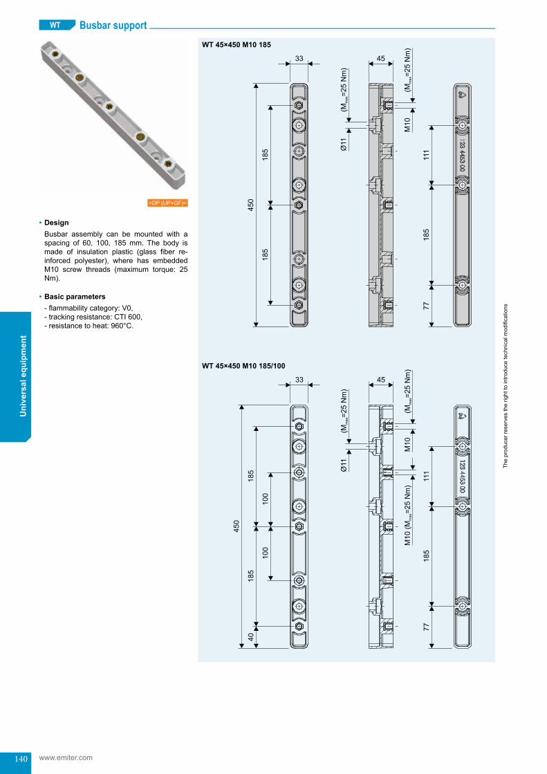
140
The
prod
ucer
rese
rves
the
right
to in
trodu
ce te
chni
cal m
odifi
catio
ns
www.emiter.com
Uni
vers
al e
quip
men
t
>DP (UP+GF)<
Busbar supportWT
WT45×450M10185
WT45×450M10185/100
•DesignBusbar assembly can be mounted with aspacing of 60, 100, 185mm. The body ismade of insulation plastic (glass fiber re-inforced polyester), where has embeddedM10 screw threads (maximum torque: 25Nm).
•Basic parameters-flammabilitycategory:V0, -trackingresistance:CTI600, -resistancetoheat:960°C.
111
185
450
100
185
100
33
M10
40
45
185
77
M10 (
M=
25 N
m)
max
(M=
25 N
m)
max
()
M=
25 N
mm
ax
Busbar support (WT)

141
The
prod
ucer
rese
rves
the
right
to in
trodu
ce te
chni
cal m
odifi
catio
ns
Uni
vers
al e
quip
men
t
6
5
2
4
3
1
4
M =25 Nmmax
WT
WT45×170M1060
type art.no.
WT 45×450 M10 185 123 4453 00WT 45×450 M10 185/100 123 4453 01WT 45×170 M10 60 123 4173 00
•Installation to steel busbar bracket60
185
33
M10
45
60
55
60
()
M=
25 N
mm
ax
()
M=
25 N
mm
ax
INSTALLATION AND USE
1. support WT2. steel busbar bracket
(an equipment item of enclosu-res ST/A type)
3. bolt M10×35 (8,8) – DIN 933, ISO 4017
4. washer M10 – DIN 125A, ISO 7089
5. spring washer – DIN 1276. nut M10 – DIN 934, ISO 4034
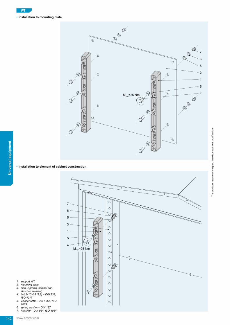
142
The
prod
ucer
rese
rves
the
right
to in
trodu
ce te
chni
cal m
odifi
catio
ns
www.emiter.com
Uni
vers
al e
quip
men
t
7
6
2
5
4
1
5
M =25 Nmmax
M =25 Nmmax
7
6
3
5
4
1
5
•Installation to mounting plate
1. support WT2. mounting plate3. side C-profile (cabinet con-
struction element)4. bolt M10×35 (8,8) – DIN 933,
ISO 40175. washer M10 – DIN 125A, ISO
70896. spring washer – DIN 1277. nut M10 – DIN 934, ISO 4034
•Installation to element of cabinet construction
WT
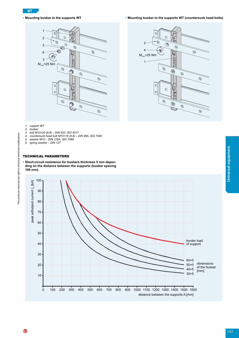
143
The
prod
ucer
rese
rves
the
right
to in
trodu
ce te
chni
cal m
odifi
catio
ns
Uni
vers
al e
quip
men
t
2
4
1
M =25 Nmmax
1
2
5
6
3
M =25 Nmmax
border loadof support
60×5
50×5
40×5
30×5
dimensionsof the busbar[mm]
100
90
80
70
60
50
40
30
20
10
0 100 200 300 400 500 600 700 800 900 1000 1100 1200 1300 1400 1500 1600
peak w
ithsta
nd c
urr
ent
I[k
A]
pk
distance between the supports A [mm]
•Mounting busbar to the supports WT
•Short-circuit resistance for busbars thickness 5 mm depen-dingonthedistancebetweenthesupports(busbarspacing100mm).
1. support WT2. busbar3. bolt M10×20 (8,8) – DIN 933, ISO 40174. countersunk head bolt M10×16 (8,8) – DIN 965, ISO 70465. washer M10 – DIN 125A, ISO 70896. spring washer – DIN 127
•MountingbusbartothesupportsWT(countersunkheadbolts)
WT
TECHNICAL PARAMETERS

144
The
prod
ucer
rese
rves
the
right
to in
trodu
ce te
chni
cal m
odifi
catio
ns
www.emiter.com
Uni
vers
al e
quip
men
t
border loadof support
60×10
50×10
40×10
30×10
dimensionsof the busbar[mm]
peak w
ithsta
nd c
urr
ent
I[k
A]
pk
distance between the supports A [mm]
100
90
80
70
60
50
40
30
20
10
0 100 200 300 400 500 600 700 800 900 1000 1100 1200 1300 1400 1500 1600
60×5
50×5
40×5
30×5
dimensionsof the busbar[mm]
border loadof support
100
90
80
70
60
50
40
30
20
10
0 100 200 300 400 500 600 700 800 900 1000 1100 1200 1300 1400 1500 1600
110
120
peak w
ithsta
nd c
urr
ent
I[k
A]
pk
distance between the supports A [mm]
•Short-circuit resistance for busbars thickness 10 mm depen-dingonthedistancebetweenthesupports(busbarspacing100mm).
•Short-circuit resistance for busbars thickness 5 mm depen-dingonthedistancebetweenthesupports(busbarspacing185mm).
WT
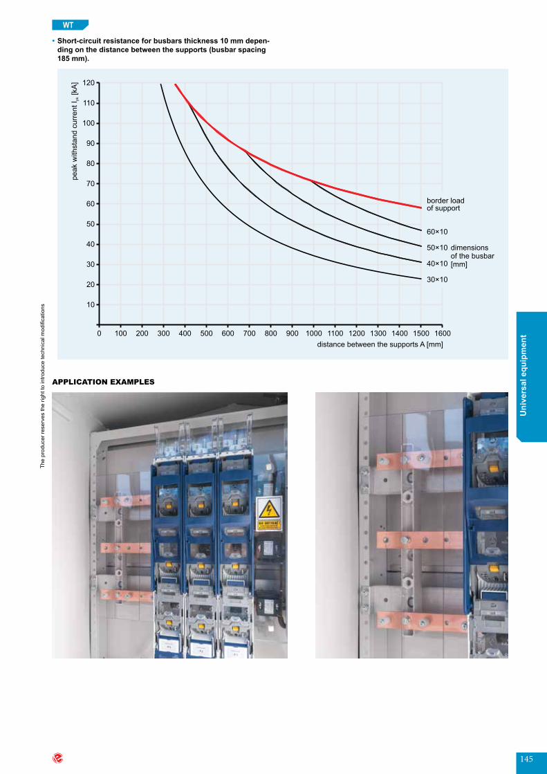
145
The
prod
ucer
rese
rves
the
right
to in
trodu
ce te
chni
cal m
odifi
catio
ns
Uni
vers
al e
quip
men
t
60×10
50×10
40×10
30×10
dimensionsof the busbar[mm]
border loadof support
100
90
80
70
60
50
40
30
20
10
0 100 200 300 400 500 600 700 800 900 1000 1100 1200 1300 1400 1500 1600
110
120
peak w
ithsta
nd c
urr
ent
I[k
A]
pk
distance between the supports A [mm]
•Short-circuit resistance for busbars thickness 10 mm depen-dingonthedistancebetweenthesupports(busbarspacing185mm).
WT
APPLICATION EXAMPLES
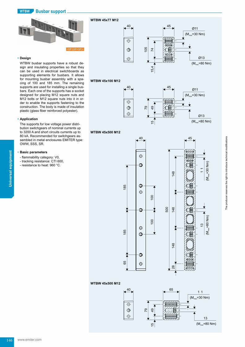
146
The
prod
ucer
rese
rves
the
right
to in
trodu
ce te
chni
cal m
odifi
catio
ns
www.emiter.com
Uni
vers
al e
quip
men
tBusbar supportWTBW
WTBW 45x77 M12
WTBW 45x100 M12
WTBW 45x500 M12
WTBW 45x500 M12
40 45
74
105
15,4
(M =30 Nm)max
(M =80 Nm)max
40 45
49
79
15
(M =30 Nm)max
(M =80 Nm)max
40
185
185
100
100
65
45
500
148
148
148
28
(M=
30 N
m)
max
(M=
80 N
m)
max
11
13
40
49
79
15
65
(M =80 Nm)max
(M =30 Nm)max
13
1 1
>DP (UP+GF)<
•DesignWTBWbusbar supportshavea robust de-sign and insulating properties so that theycan be used in electrical switchboards assupporting elements for busbars. It allowsformounting busbar assembly with a spa-cing of 100 and 185 mm. The remainingsupports are used for installing a single bus-bars.Eachoneofthesupportshasasocketdesigned for placing M12 square nuts and M12 bolts or M12 square nuts into it in or-der toenable thesupports fastening to theconstruction.Thebodyismadeofinsulationplastic(glassfiberreinforcedpolyester).
•ApplicationThesupportsforlowvoltagepowerdistri-butionswitchgearsofnominalcurrentsupto3200Aandshortcircuitscurrentsupto80kA.Recommendedforswitchgearsas-sembledinmetalenclosuresEMITERtype:OWW,SSS,SR.
•Basic parameters-flammabilitycategory:V0, -trackingresistance:CTI600, -resistancetoheat:960°C.
Busbar support (WTBW)
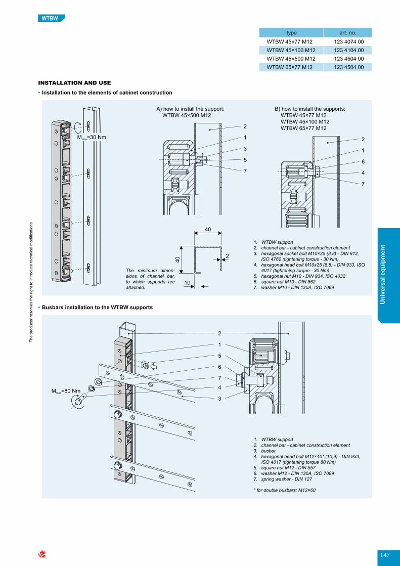
147
The
prod
ucer
rese
rves
the
right
to in
trodu
ce te
chni
cal m
odifi
catio
ns
Uni
vers
al e
quip
men
t
WTBW
type art.no.
WTBW 45×77 M12 123 4074 00WTBW 45×100 M12 123 4104 00WTBW 45×500 M12 123 4504 00WTBW 65×77 M12 123 4504 00
•Installation to the elements of cabinet construction
•Busbars installation to the WTBW supports
A)howtoinstallthesupport: WTBW 45×500 M12
The minimum dimen-sions of channel bar, to which supports are attached.
B)howtoinstallthesupports: WTBW 45×77 M12 WTBW 45×100 M12 WTBW 65×77 M12
INSTALLATION AND USE
1. WTBW support2. channel bar - cabinet construction element3. hexagonal socket bolt M10×25 (8.8) - DIN 912,
ISO 4762 (tightening torque - 30 Nm)4. hexagonal head bolt M10x25 (8.8) - DIN 933, ISO
4017 (tightening torque - 30 Nm)5. hexagonal nut M10 - DIN 934, ISO 40326. square nut M10 - DIN 5627. washer M10 - DIN 125A, ISO 7089
M =30 Nmmax
1. WTBW support2. channel bar - cabinet construction element3. busbar4. hexagonal head bolt M12×40* (10,9) - DIN 933,
ISO 4017 (tightening torque 80 Nm)5. square nut M12 - DIN 5576. washer M12 - DIN 125A, ISO 70897. spring washer - DIN 127
* for double busbars: M12×60

148
The
prod
ucer
rese
rves
the
right
to in
trodu
ce te
chni
cal m
odifi
catio
ns
www.emiter.com
Uni
vers
al e
quip
men
tWTBW
•BusbarsinstallationtotheWTBWsupports(countersunkheadbolts)
•WTBW45×100M12,WTBW45×77M12-maximumloadofthesupport:800[kg]
•WTBW 45×500 M12
•WTBW65×77M12-maximumloadofthesupport:1000[kg]
ATTENTION! The calculation, in addition to the resistance of supports on short--circuit currents, takes into account the strength of the busbar and interference of vibrations, but does not take into account the transverse force acting at the busbar while opening disconnectors.
1. WTBW support2. channel bar - cabinet construction element3. busbar4. countersunk head bolt M12×40* (10,9) - DIN7991
(tightening torque 80 Nm)5. square nut M12 - DIN 557
* for double busbars: M12×60
TECHNICAL PARAMETERS
no.anddimensions of Cu busbars
[mm]
rated current Ir [A] - directconnection
(1:1)
rated transformer
power [kVA] - direct
connection (1:1)
short-timewithstandcurrentIcw [kA]
25 30 40 50 60 65 70 80
peakwithstandcurrentIpk [kA]
53 63 84 105 132 143 154 176
maximum support distance [mm]
1×40×10 840 582 1000 897 505 323 224 191 165 126
2×40×10 1510 1046 1000 1000 1000 610 458 390 336 257
1×50×10 1000 693 1000 1000 782 590 347 296 259 195
2×50×10 1770 1226 1000 1000 1000 500 480 410 350 270
1×60×10 1155 800 1000 1000 1000 590 460 390 340 250
2×60×10 2015 1396 1000 1000 1000 600 470 400 350 260
1×80×10 1450 1005 1000 1000 1000 590 460 390 340 250
2×80×10 2470 1711 1000 1000 1000 600 470 400 340 250
1×100×10 1745 1209 1000 1000 1000 580 460 390 340 250
2×100×10 2900 2009 1000 1000 1000 590 460 390 340 250
1×120×10 2035 1410 1000 1000 1000 570 450 380 330 245
2×120×10 3350 2321 1000 1000 1000 570 450 380 330 245
1×160×10 2700 1871 1000 1000 1000 500 395 335 290 210
2×160×10 4350 3014 1000 1000 1000 500 400 340 290 215

149
The
prod
ucer
rese
rves
the
right
to in
trodu
ce te
chni
cal m
odifi
catio
ns
Uni
vers
al e
quip
men
t
WTBW
APPLICATION EXAMPLES
Power busbar support (horizontal)WTBW 45×410 M12
WTBW 45×410 M12
>DP (UP+GF)<
•DesignWTBW 45×410 M12 power busbar support hasrobustdesignandinsulatingproperties,thatcanbeusedinelectricalswitchgearstosupport power busbars. This allows powerbusbars to be mounted vertically, to supply main switch-disconnector and vertical out-flowbusbarsfrommainswitch-disconnectortohorizontalbusbarsforverticaloutflowfuseoutgoing strips. It can be mounted to thecabinet in a horizontal position using M10boltsandnuts.Thesupporthas4holesand sockets designed for placement of square M12nutstoenablebusbarsmounting.Thespacingoftheholesprovidessupportforthepowerfeedingbusbarsandoutflowsbusbarsfrommainswitch-disconnectorfor4varioustypesofswitch-disconnectorswith1250[A]ratedcurrentproducedby:Telergon,Sirco,JeanMuellerandEFEN.DifferentspacingofthephasebusbarsandPENbusbaroftheswitch-disconnectorsandpowerbusbarsupportarecompensatedbyanoffsetofthefixingholesintheverticalbusbaroftheswitchgear,withaxesofthebusbars.
Power busbar support - horizontal (WTBW 45×410 M12)

150
The
prod
ucer
rese
rves
the
right
to in
trodu
ce te
chni
cal m
odifi
catio
ns
www.emiter.com
Uni
vers
al e
quip
men
tWTBW 45×410 M12
•ApplicationSupportforlowvoltagepowerdistributionswitchgearofratedcurrentupto3200[A]andshortcircuitscurrentupto80[kA].Recommen-dedforswitchgearsassembledinmetalenclosuresEmitertype:NTw,OWW,SSS,SR.
•Basic parameters-flammabilitycategory:V0, -trackingresistance:CTI600, -resistancetoheat:960°C.
INSTALLATION METHOD•Installationwithinthecabinet
•Busbar installation to the WTBW 45×410 M12 support
1. busbar support WTBW 45×410 M122. horizontal reinforcement of the NTw cabinet over
switch-disconnector3. power busbar4. hexagonal head bolt M12×45 (10,9) - DIN 933,
ISO 4017 (tightening torque 80 Nm)5. square nut M12 - DIN 5576. washer M12 - DIN 125A, ISO 70897. spring washer - DIN 127
1. busbar support WTBW 45×410 M122. horizontal reinforcement of the NTw cabinet over
switch-disconnector3. hexagonal socket bolt M10x20 (8.8) - DIN 912,
ISO 4762 (tightening torque 30 Nm)4. hexagonal nut M10 - DIN 934, ISO 40325. washer M10 - DIN 125 A, ISO 7089
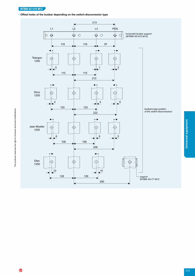
151
The
prod
ucer
rese
rves
the
right
to in
trodu
ce te
chni
cal m
odifi
catio
ns
Uni
vers
al e
quip
men
t
WTBW 45×410 M12
•Offsetholesofthebusbardependingontheswitch-disconnectortype

152
The
prod
ucer
rese
rves
the
right
to in
trodu
ce te
chni
cal m
odifi
catio
ns
www.emiter.com
Uni
vers
al e
quip
men
t
TECHNICAL PARAMETERS
WTBW 45×410 M12
APPLICATION EXAMPLE
no.anddimensions of Cu busbars
[mm]
rated current Ir [A]
transformer power [kVA]
short-timewithstandcurrentIcw [kA]
25 30 40 50 60 65 70 80
peakwithstandcurrentIpk [kA]
53 63 84 105 132 143 154 176
maximumdistancefromtheswitch-disconnector-L[mm]
1×50×10 (I) 1060 693 200 200 200 200 200 200 200 200
2×50×10 (II) 1770 1226 200 200 200 200 200 200 200 200
1×60×10 (I) 1155 800 200 200 200 200 200 200 200 200
2×60×10 (II) 2015 1396 200 200 200 200 200 200 200 200
1×80×10 (I) 1450 1005 200 200 200 200 200 200 200 200
2×80×10 (II) 2470 1711 200 200 200 200 200 200 200 200
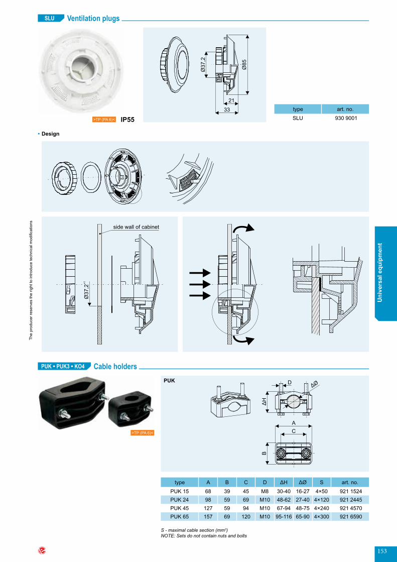
153
The
prod
ucer
rese
rves
the
right
to in
trodu
ce te
chni
cal m
odifi
catio
ns
Uni
vers
al e
quip
men
t
Ventilation plugs
Cable holders
SLU
Ø8
5
Ø3
7,2
21
33
>TP (PA 6)< IP55
•Design
Ø3
7,2
+1
side wall of cabinet
type art.no.
SLU 930 9001
PUK • PUK3 • KO4
CA
B
D
ΔH
ΔØPUK
type A B C D ΔH ΔØ S art.no.
PUK 15 68 39 45 M8 30-40 16-27 4×50 921 1524PUK 24 98 59 69 M10 48-62 27-40 4×120 921 2445PUK 45 127 59 94 M10 67-94 48-75 4×240 921 4570PUK 65 157 69 120 M10 95-116 65-90 4×300 921 6590
S - maximal cable section (mm2)NOTE: Sets do not contain nuts and bolts
>TP (PA 6)<
Ventilation plugs (SLU)Cable holders (PUK, PUK3, KO4)
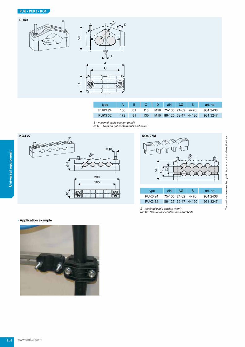
154
The
prod
ucer
rese
rves
the
right
to in
trodu
ce te
chni
cal m
odifi
catio
ns
www.emiter.com
Uni
vers
al e
quip
men
tPUK • PUK3 • KO4
PUK3
type A B C D ΔH ΔØ S art.no.
PUK3 24 150 81 110 M10 75-105 24-32 4×70 931 2436PUK3 32 172 81 130 M10 86-125 32-47 4×120 931 3247
type ΔH ΔØ S art.no.
PUK3 24 75-105 24-32 4×70 931 2436PUK3 32 86-125 32-47 4×120 931 3247
S - maximal cable section (mm2)NOTE: Sets do not contain nuts and bolts
S - maximal cable section (mm2)NOTE: Sets do not contain nuts and bolts
ØΔ
2645ΔH
165200
40ΔH
M10
ΔØ
KO4 27 KO4 27M
•Application example
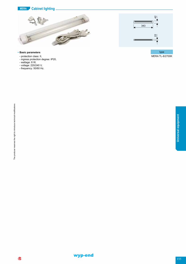
155
The
prod
ucer
rese
rves
the
right
to in
trodu
ce te
chni
cal m
odifi
catio
ns
Uni
vers
al e
quip
men
t
Cabinet lightingMERA
type
MERA TL-8/2700K•Basic parameters-protectionclass:II, -ingressprotectiondegree:IP20, -wattage:8W, -voltage:220/240V, -frequency:50/60Hz.
wyp-end
Cabinet lighting (MERA)


Technical information
inf-start
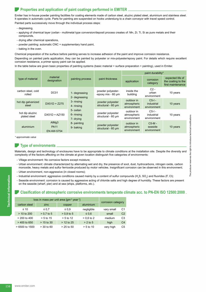
158
The
prod
ucer
rese
rves
the
right
to in
trodu
ce te
chni
cal m
odifi
catio
ns
www.emiter.com
Tech
nica
l inf
orm
atio
n
Materials,designandtechnologyofenclosureshavetobeappropriatetoclimateconditionsattheinstallationsite.Despitethediversityandcomplexityofthefactorsaffectingontheclimateatgivenlocationdistinguishfivecategoriesofenvironments:
- Villageenvironment:Nocorrosivefactorsexceptmoisture; - Urbanenvironment:climatecharacterizedbyalternatingwetanddry,thepresenceofsoot,dust,hydrocarbons,nitrogenoxide,carbonmonoxide,heavymetalsandsulfurferrioxideproducedbymotorvehicles.Insignificantcorrosioncanbeobservedinthisenvironment;
- Urbanenvironment,non-aggressive(inclosedrooms); - Industrialenvironment:aggressiveconditionscausedmainlybyacontentofsulfurcompounds(H2S, SO2)andfluorides(F,Cl); - Seasideenvironment:corrosioniscausedbyaggressiveactingofchloridesaltsandhighdegreeofhumidity.Thesefactorsarepresentontheseaside(wharf,pier)andatsea(ships,platforms,etc.).
Properties and application of paint coatings performed in EMITER
Type of environments
Clasification of atmospheric corrosive environments temperate climate acc. to PN-EN ISO 12500:2000
Emiterhasin-housepowderpaintingfacilitiesforcoatingelementsmadeofcarbonsteel,aluzincplatedsteel,aluminiumandstainlesssteel.Itoperatesinautomaticcycle.Partsforpaintingaresuspendedonhooksunderslungtoachainconveyorwithtravelspeedcontrol.Paintedpartssuccessivelymovethroughtheindividualprocesssteps:
- degreasing, - applyingofchemicallayer(oxilan-multimetaltypeconversion/depositprocesscreatesof:Mn,Zr,Ti,Siaspuremetalsandtheir compounds,
- dryingafterchemicaloperations, - powderpainting:automaticCNC+supplementaryhandpaint, - bakingintheoven.
Chemicalpreparationofthesurfacebeforepaintingservestoincreaseadhesionofthepaintandimprovecorrosionresistance.Dependingonpaintedpartsapplication,theycanbepaintedbypolyesterormix-polyester/epoxypaint.Fordetailswhichrequireexcellentcorrosionresistance,aprimerepoxypaintcanbeapplied.Inthetablebelowaregivenbasicpropertiesofpaintingsystems(basicmaterial+surfacepreparation+painting),usedinEmiter.
type of material material designation painting process paintthickness
paint durability*
application corrosion category
expected life of thecoatingtothefirstmaintenance
carbon steel, cold rolled DC01 1- degreasing
2- degreasing3- rinsing4- rinsing5- oxilan6- rinsing7- drying8- painting9- baking
powder polyester--epoxymix-60μm
insidethebuilding
C2 - urban
environment10 years
hotdipgalvanizedsteel DX51D + Z275 powder polyester
structural-60μm
outdoor in atmosphericenvironment
C5-I - industrial
environment10 years
hotdipaluzincplated steel DX51D + AZ150 powder polyester
structural-60μm
outdoor in atmosphericenvironment
C5-I - industrial
environment10 years
aluminiumAlMg3PA11
EN AW-5754
powder polyester structural-60μm
outdoor in atmosphericenvironment
C5-M - seaside
environment10 years
* approximate value
loss in mass per unit area [gm-2 year-1]corrosion category
carbon steel zinc copper aluminium
≤10 ≤0,7 ≤0,9 negligible vary small C1> 10 to 200 > 0,7 to 5 > 0,9 to 5 ≤0,6 small C2> 200 to 400 > 5 to 15 > 5 to 12 > 0,6 to 2 medium C3> 400 to 650 > 15 to 30 > 12 to 25 > 2 to 5 high C4
> 6500 to 1500 > 30 to 60 > 25 to 50 > 5 to 10 veryhigh C5
Properties and application of paint coatings performed in EMITERType of environmentsClasification of atmospheric corrosive environments temperate climate acc. to PN-EN ISO 12500:2000

159
The
prod
ucer
rese
rves
the
right
to in
trodu
ce te
chni
cal m
odifi
catio
ns
Tech
nica
l inf
orm
atio
n
Types of treatments and coatings, depending on the operating conditions for the durability of the coating 10 years to first maintenance. Not used in Emiter
Salt mist test duration versus corrosion category type for the durability of the coating 10 years to first maintenance
•Primerpaintisapplieddirectlyonmetalchemicalpreparedbyphosphatingoroxilanlayer.•FinishpaintmustbeUVresistant,resistantagainstwater,gas,dust,mechanicaldamages,chemicals,etc.Mustbetightandcontinuousallthetimeduringexpectedlifetimeoftheproduct.
operating environmental
conditions
corrosion category zinccoatingsonsteelsheet zincplatedsteelsheetpaintedwithdifferentpaintingsystems
atmosphericcon-ditionsonthehigh
seasC5-M
•Zn>100μmor•Z 600
•1×zinclayer(50μm)+1×midcoat(primer60μm)+2×finishpaint(150μm)
seasideatmosphe-ric conditions C5-M
•Zn>70μmor•Z 450 or•flZn1500
•1×zinclayer(50μm)+1×midcoat(primer60μm)+2×finish coatings(150μm)
industrial environment C5-I
•Zn25μmor•Z 350 or•flZn1000
•1×zinclayer(30μm)+1×midcoat(primer30μm)+2×finishpaint(120μm)
mixed environment urban-village C4
•Zn 15 or•Z 275 or•flZn500
•1×zinclayer(30μm)+2×finishpaint(120μm)or
•Z140+1×primerpaint(30μm)+2×finishpaint(120μm)
aggressive moist environment C3
•Zn 12 or•Z 200
•Z140+1×primerpaint(30μm)+2×finishpaint(120μm)
moist environment C2•Zn 8 or•Z140(10μm)
•Zn5+2×finishpaint(120μm)or•Z100+1×primerpaint(30μm)+1×finishpaint(50μm)
dry environment C1•Z 100•Zn 5
•Zn5+2×finishpaint(60μm)or•1×primerpaint(20μm)+1×finishpaint(50μm)
Zn xx - electrolytic zinc with a minimum thickness xx in μm (ISO 2081, ISO 4042)Z xxx - hot deep zinc coating with layer weight xxx g/m2 (both side) EN 10292, EN 10326, EN 10327fl Zn xxx - sprinkle zinc, xxx - salt mist resistance ISO 10383
operating conditions corrosion category paint coatings non-paint coatings
environmentonthehighseas C5-M 2000h 2000hseaside environment C5-M 1500h 1500h
industrial environment C5-I 1500h 1000hmixed urban-village environment C4 1000h 500h
aggressive moist internal or village not contaminated environment C3 500h 168hmoist environment C2 250h 500h
dry environment (temporary moist) C2 168h 96hdry environment C1 96h 24h
Types of treatments and coatings, depending on the operating conditions for the durability of the co-ating 10 years to first maintenance. Not used in Emiter.Salt mist test duration versus corrosion category type for the durability of the coating 10 years to first maintenance

160
The
prod
ucer
rese
rves
the
right
to in
trodu
ce te
chni
cal m
odifi
catio
ns
www.emiter.com
Tech
nica
l inf
orm
atio
n
coating codetheoreticalreference
value for coating thicknessperside[µm]
range of coating thicknessperside[µm]
Z 275 20 15 - 27Z 350 25 19 - 33
AZ 150 20 15 - 27AZ 185 25 19 - 33
Loss of zinc and aluzinc layer thickness depending on environment conditions
Materials versus electrolytic corrosion avoidance
Thickness of the zinc and aluzinc layer
Durability of the coating
corrosion category aggressiveness
type of environmentloss of zinc layer loss of aluzinc layer
external internal
C1very small -
Heatedbuildingswithpureatmosphere,e.g.offices,schools,shops,hotels,etc.
≤0,1µm/year ≤0,02µm/year
C2small
Environmentwithsmallrateofcontamination.
Nonheatedbuildings,subject to condensation e.g.warehouses,sportshalls.
>0,1do0,7µm/year >0,02do0,14µm/year
C3medium
Urban and industrial envi-ronments. Medium conta-minated of sulphur oxide(IV);Seasidewithsmallsalinity.
Productionhallswithhighhumidityandcertainaircontaminatione.g.foodplants, breweries, dairies, laundries.
>0,7do2,1µm/year >0,14do0,42µm/year
C4high
Industrial environments andseasidewithmediumrateofsalinity.
Chemicalplants,swim-mingpools,repairyards. >2,1do4,2µm/year >0,42do0,84µm/year
C5-Iveryhigh(industrial)
Industrial environments withhighmoistandag-gressivecontamination.
Buildings and areas withalmostcontinuouscondensationandhighcontamination.
>4,2do8,2µm/year >0,84do1,64µm/year
C5-Mveryhigh(marine)
Seaside and marine envi-ronment.
Buildings and areas withalmostcontinuouscondensationandhighcontamination.
>4,2do8,2µm/year >0,84do1,64µm/year
corrosion category
metalliccoatingswithoutpaintuntilappearanceofredcorrosion*[years]
coatings-polyesterpowderpaint,thickness100μmonmetallicsurfaceuntilappearanceofwhite
corrosion* [years]
Z 275 Z 350 AZ 150 AZ 185 Z 275Z 350
AZ 150AZ 185 AlMg3
C4 3,5 - 12,8 4,5 - 15,7 17,5 - 64 22,5 - 78,5 10+ 10+ 15C5-I 1,8 - 6,4 2,3 - 7,8 9 - 32 11,5 - 39 7 7 10C5-M 1,8 - 6,4 2,3 - 7,8 9 - 32 11,5 - 39 7 7 10
connecting elements (rivet, screw, bolt)
type of material
steelwithoutcoating stainless steel zinc plated steel aluminium copper
steelwithoutcoating ○ × × × ○stainless steel × ● × × ○tin plated steel ● × ○ ○ ○
zinc plated steel ● × ● ○ ×aluminium × × ○ ● ×
copper ○ ○ × × ●brasswithoutcoating ○ ○ × × ●
tin plated brass ○ × ○ ○ ●nickel plated brass ○ ○ ○ × ●
●recommended○possible×notrecommended
* approximate value
Loss of zinc and aluzinc layer thickness depending on environment conditionsThickness of the zinc and aluzinc layerDurability of the coatingMaterials versus electrolytic corrosion avoidance

161
The
prod
ucer
rese
rves
the
right
to in
trodu
ce te
chni
cal m
odifi
catio
ns
Tech
nica
l inf
orm
atio
n
Tightening moments for bolts used in electrical connections
Current carrying capacity of copper busbars
threadsizeminimun tightening
moment [Nm]
strengthgradeofbolts
8,8 10,9 12,9
maximumtighteningmoment[Nm]
M8 18 27 35 40M10 35 47 66 77M12 60 80 113 207M14 95 129 177 282M16 130 173 242 282
•ContinuouscurrentsforCubusbarsforrectangularcross-sectionininternalsystemsat+35°Cairtemperatureand+65°Cbartemperatu-reatverticalbarposition,accordingtoDIN43670.
Note: Do not use bolts with grade lower than 6.8
* specific gravity of Cu - 8,9 g/cm3
width×thickness
[mm]
cross section[mm2]
weight*
[kg/m]
continuous current [A]
AC up to 60 Hz DC/AC up to 16,66 Hz
coated(number of bars)
uncoated(number of bars)
coated(number of bars)
uncoated(number of bars)
I II I II I II I II
12×2 23,5 0,209 123 202 108 182 123 202 108 18215×2 29,5 0,262 148 240 128 212 148 240 128 21215×3 44,5 0,396 187 316 162 282 187 316 162 28220×2 39,5 0,351 189 302 162 264 189 302 162 26620×3 59,5 0,529 237 394 204 348 237 394 204 34820×5 99,1 0,882 319 560 274 500 320 562 274 50220×10 199 1,77 497 924 427 852 499 932 428 83225×3 74,5 0,663 287 470 245 412 287 470 245 41425×5 124 1,11 384 662 327 586 384 664 327 59030×3 89,5 0,796 337 544 285 476 337 546 286 47830×5 149 1,33 447 760 379 672 448 766 380 67630×10 299 2,66 676 1200 573 1060 683 1230 597 108040×3 119 1,06 435 692 366 600 436 696 367 60440×5 199 1,77 573 952 482 836 576 966 484 87840×10 399 3,55 850 1470 715 1290 865 1530 728 135050×5 249 2,22 697 1140 583 994 703 1770 588 102050×10 499 4,44 1020 1720 852 1510 1050 1830 857 161060×5 299 2,66 826 1330 688 1150 836 1370 696 119060×10 599 5,33 1180 1960 985 1720 1230 2130 1020 187080×5 399 3,55 1070 1680 885 1450 1090 1770 902 153080×10 799 7,11 1500 2410 1240 2110 1590 2730 1310 2380100×5 499 4,44 1300 2010 1080 1730 1340 2160 1110 1810100×10 999 8,99 1810 2850 1490 2480 1940 3310 1600 2890120×10 1200 10,7 2110 3280 1740 2860 2300 3900 1890 3390160×10 1600 14,2 2700 4130 2220 3590 3010 5060 2470 4400200×10 2000 17,8 3290 4970 2690 4310 3720 6220 3040 5390
Tightening moments for bolts used in electrical connectionsCurrent carrying capacity of copper busbars
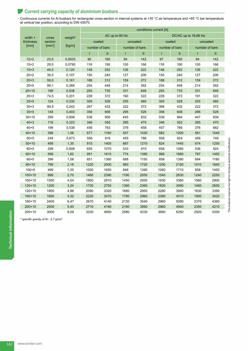
162
The
prod
ucer
rese
rves
the
right
to in
trodu
ce te
chni
cal m
odifi
catio
ns
www.emiter.com
Tech
nica
l inf
orm
atio
nCurrent carrying capacity of aluminium busbars
•ContinuouscurrentsforAlbusbarsforrectangularcross-sectionininternalsystemsat+35°Cairtemperatureand+65°Cbartemperatureatverticalbarposition,accordingtoDIN43670.
width×thickness
[mm]
cross section[mm2]
weight*
[kg/m]
conditions current [A]
AC up to 60 Hz DC/AC up to 16,66 Hz
coated uncoated coated uncoated
number of bars number of bars number of bars number of bars
I II I II I II I II
12×2 23,5 0,0633 90 160 84 142 97 160 84 14215×2 29,5 0,0795 118 190 100 166 118 190 100 16615×3 44,5 0,120 148 252 126 222 148 252 126 22220×2 39,5 0,107 150 240 127 206 150 240 127 20620×3 59,5 0,161 188 312 159 272 188 312 159 27220×5 99,1 0,268 254 446 214 392 254 446 214 39220×10 199 0,538 293 730 331 646 293 733 331 64625×3 74,5 0,201 228 372 190 322 228 372 191 32225×5 124 0,335 305 526 255 460 305 528 255 46030×3 89,5 0,242 267 432 222 372 368 432 222 37230×5 149 0,403 356 606 295 526 356 608 296 52830×10 299 0,808 536 956 445 832 538 964 447 83940×3 119 0,323 346 550 285 470 346 552 285 47040×5 199 0,538 456 763 376 658 457 766 376 66240×10 399 1,08 677 1180 557 1030 682 1200 561 104050×5 249 0,673 556 916 455 786 558 924 456 74950×10 499 1,35 815 1400 667 1210 824 1440 674 125060×5 299 0,808 655 1070 533 910 658 1080 536 92460×10 599 1,62 951 1610 774 1390 966 1680 787 145080×5 399 1,08 851 1360 688 1150 858 1390 694 118080×10 799 2,16 1220 2000 983 1720 1250 2150 1010 1840100×5 499 1,35 1050 1650 846 1390 1060 1710 858 1450100×10 999 2,70 1480 2390 1190 2050 1540 2630 1240 2250100×15 1500 4,04 1800 2910 1450 2500 1930 3380 1560 2900120×10 1200 3,24 1730 2750 1390 2360 1830 3090 1460 2650120×15 1800 4,86 2090 3320 1680 2850 2280 3950 1830 3390160×10 1600 4,32 2220 3470 1780 2960 2380 4010 1900 3420160×15 2400 6,47 2670 4140 2130 3540 2960 5090 2370 4360200×10 2000 5,40 2710 4180 2160 3560 2960 4940 2350 4210200×15 3000 8,09 3230 4950 2580 4230 3660 6250 2920 5350
* specific gravity of Al - 2,7 g/cm3
Current carrying capacity of aluminium busbars
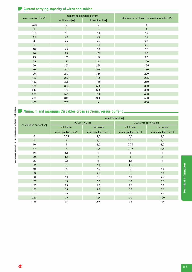
163
The
prod
ucer
rese
rves
the
right
to in
trodu
ce te
chni
cal m
odifi
catio
ns
Tech
nica
l inf
orm
atio
n
continuous current [A]
rated current [A]
AC up to 60 Hz DC/AC up to 16,66 Hz
minimum maximum minimum maximum
cross section [mm2] cross section [mm2] cross section [mm2] cross section [mm2]
6 0,75 1,5 0,5 1,58 1 2,5 0,75 2,510 1 2,5 0,75 2,512 1 2,5 0,75 2,516 1,5 4 1 420 1,5 6 1 425 2,5 6 1,5 432 2,5 10 1,5 640 4 16 2,5 1063 6 25 6 1680 10 35 10 25100 16 50 16 35125 25 70 25 50160 35 95 35 70200 50 120 50 95250 70 150 70 120315 95 240 95 185
Current carrying capacity of wires and cables
Minimum and maximum Cu cables cross sections, versus current
cross section [mm2]maximum allowable current
rated current of fuses for circuit protection [A]continuous [A] intermittent [A]
0,75 9 9 61 11 11 6
1,5 14 14 102,5 20 20 154 25 25 206 31 31 2510 43 60 3516 75 105 6025 100 140 8035 125 175 10050 160 225 12570 200 280 16095 240 335 200120 280 400 225150 325 460 260185 380 530 300240 450 630 350300 525 730 430400 640 900 500500 760 - 600
Current carrying capacity of wires and cablesMinimum and maximum Cu cables cross sections, versus current
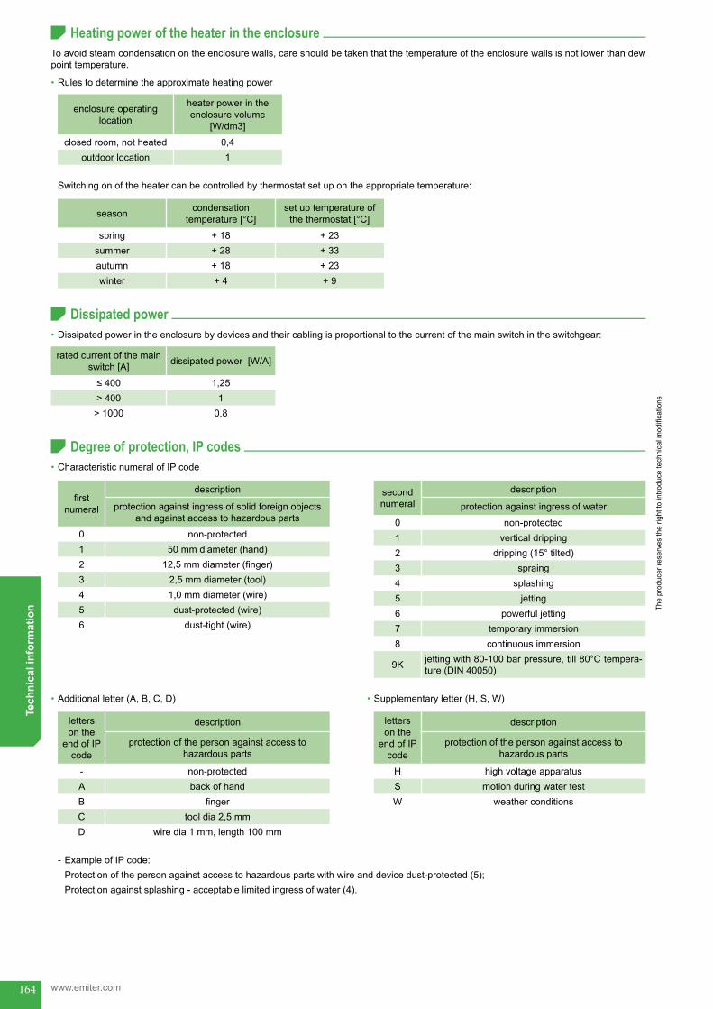
164
The
prod
ucer
rese
rves
the
right
to in
trodu
ce te
chni
cal m
odifi
catio
ns
www.emiter.com
Tech
nica
l inf
orm
atio
n
firstnumeral
description
protection against ingress of solid foreign objects andagainstaccesstohazardousparts
0 non-protected1 50mmdiameter(hand)2 12,5mmdiameter(finger)3 2,5 mm diameter (tool)4 1,0 mm diameter (wire)5 dust-protected (wire)6 dust-tight(wire)
Heating power of the heater in the enclosure
Dissipated power
Degree of protection, IP codes
enclosure operating location
heaterpowerintheenclosure volume
[W/dm3]
closedroom,notheated 0,4outdoor location 1
season condensation temperature[°C]
set up temperature of thethermostat[°C]
spring + 18 + 23summer + 28 + 33autumn + 18 + 23winter + 4 + 9
Toavoidsteamcondensationontheenclosurewalls,careshouldbetakenthatthetemperatureoftheenclosurewallsisnotlowerthandewpointtemperature.
•Rulestodeterminetheapproximateheatingpower
Switchingonoftheheatercanbecontrolledbythermostatsetupontheappropriatetemperature:
•Dissipatedpowerintheenclosurebydevicesandtheircablingisproportionaltothecurrentofthemainswitchintheswitchgear:
•CharacteristicnumeralofIPcode
•Additional letter (A, B, C, D) •Supplementary letter (H, S, W)
- ExampleofIPcode:Protectionofthepersonagainstaccesstohazardouspartswithwireanddevicedust-protected(5);Protection against splashing-acceptablelimitedingressofwater(4).
ratedcurrentofthemainswitch[A] dissipated power [W/A]
≤400 1,25> 400 1
> 1000 0,8
second numeral
description
protection against ingress of water
0 non-protected1 vertical dripping2 dripping(15°tilted)3 spraing4 splashing5 jetting6 powerful jetting7 temporary immersion8 continuous immersion
9K jettingwith80-100barpressure,till80°Ctempera-ture (DIN 40050)
letters onthe
end of IP code
description
protectionofthepersonagainstaccesstohazardousparts
- non-protectedA backofhandB fingerC tool dia 2,5 mmD wiredia1mm,length100mm
letters onthe
end of IP code
description
protectionofthepersonagainstaccesstohazardousparts
H highvoltageapparatusS motion during water testW weatherconditions
Heating power of the heater in the enclosureDissipated powerDegree of protection, IP codes

165
The
prod
ucer
rese
rves
the
right
to in
trodu
ce te
chni
cal m
odifi
catio
ns
Tech
nica
l inf
orm
atio
n
Impact protection, IK codes
Metal enclosures with protection class IIB
IK codecharacterizesabilityoftheequipmenttoresistmechanicalimpactonallsides(EN50102).
IIBprotectionclasscanbeobtainedthrough:
- appropriate design solution, - additionalinsulationofthecircuitsanddevices.
•Example of IK code - IK01withstandenergyofimpact-0,15J
IK code impact energy [J] hammermass
[kg]heightofhammer
elevation [cm]
00 0 - -01 0,15 0,2 7,502 0,20 0,2 1003 0,35 0,2 17,504 0,50 0,2 2505 0,70 0,2 3506 1 0,5 2007 2 0,5 4008 5 1,7 29,509 10 5 2010 20 5 40
featureprotection class IIB obtained by enclosure design protection class IIB obtained by additional insulation
of installation
IIB - K IIB - I
protection idea
•metal enclosure• internal side of enclosure completely covered by
insulation layer•paintedelementmustbecoveredwithpartitions• insulation distance must be maintained between
metal conductive and non-conductive parts and PE connectors
•protectionagainstcontactwithenclosureorothermetal parts torn or burnt wires
•standard enclosure, non-covered by insulation layer, withoutearthterminal
•circuits protected by differential current relays•additional insulation of apparatus by insulation
partitions, or•mounting of II class protection degree apparatus +
additional insulation of wires and cables• ifthewiresandcablesarenotmadeinprotectionclassII,shouldbeleadininsulationsheathorcombchannel
•applicationofadditionalsheathsofcableterminals
PE protective conductors• insulated from metal conductive and non-conductive parts, and enclosure•devicescanbeconnectedtoPEterminals(equipotentialconnection)butnotconnectedtothemainPE
terminals of installation
earthterminalmarkofexternal mass
insulation of PE terminals required, as conductive partsresponsibility for II class protection maintenance
1- enclosure manufacturer2-switchgearassembler
1-switchgearassembler
necessity of enclosure certificationasIIclassprotected
yes no
Impact protection, IK codesMetal enclosures with protection class IIB
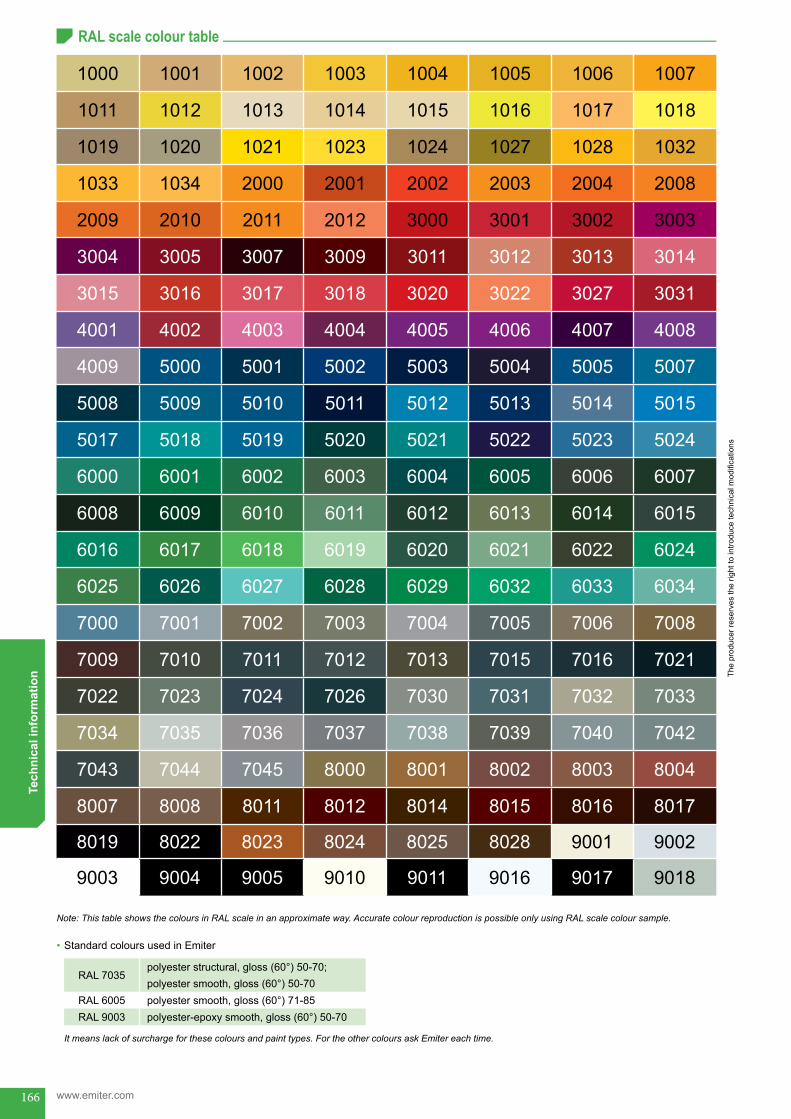
166
The
prod
ucer
rese
rves
the
right
to in
trodu
ce te
chni
cal m
odifi
catio
ns
www.emiter.com
Tech
nica
l inf
orm
atio
n
1000 1001 1002 1003 1004 1005 1006 1007
1011 1012 1013 1014 1015 1016 1017 1018
1019 1020 1021 1023 1024 1027 1028 1032
1033 1034 2000 2001 2002 2003 2004 2008
2009 2010 2011 2012 3000 3001 3002 3003
3004 3005 3007 3009 3011 3012 3013 3014
3015 3016 3017 3018 3020 3022 3027 3031
4001 4002 4003 4004 4005 4006 4007 4008
4009 5000 5001 5002 5003 5004 5005 5007
5008 5009 5010 5011 5012 5013 5014 5015
5017 5018 5019 5020 5021 5022 5023 5024
6000 6001 6002 6003 6004 6005 6006 6007
6008 6009 6010 6011 6012 6013 6014 6015
6016 6017 6018 6019 6020 6021 6022 6024
6025 6026 6027 6028 6029 6032 6033 6034
7000 7001 7002 7003 7004 7005 7006 7008
7009 7010 7011 7012 7013 7015 7016 7021
7022 7023 7024 7026 7030 7031 7032 7033
7034 7035 7036 7037 7038 7039 7040 7042
7043 7044 7045 8000 8001 8002 8003 8004
8007 8008 8011 8012 8014 8015 8016 8017
8019 8022 8023 8024 8025 8028 9001 9002
9003 9004 9005 9010 9011 9016 9017 9018
RAL scale colour table
Note: This table shows the colours in RAL scale in an approximate way. Accurate colour reproduction is possible only using RAL scale colour sample.
•Standard colours used in Emiter
It means lack of surcharge for these colours and paint types. For the other colours ask Emiter each time.
RAL 7035polyesterstructural,gloss(60°)50-70;polyestersmooth,gloss(60°)50-70
RAL 6005 polyestersmooth,gloss(60°)71-85RAL 9003 polyester-epoxysmooth,gloss(60°)50-70
RAL scale colour table
inf-end

ul.Skrudlak3 34-600 Limanowa
Metal Enclosure Departmenttel.: mobile: fax:
e-mail:
Z.U.P. EMITER Sp. J.
www.emiter.com
0048 18 333 76 44 0048 18 333 76 45 0048 513 087 736 0048 18 337 00 91
2014
EN