metal-oxide varistors (movs) radial lead varistors > za...
TRANSCRIPT
© 2018 Littelfuse, Inc.Specifications are subject to change without notice.
Revised: 12/12/18
Metal-Oxide Varistors (MOVs)Radial Lead Varistors > ZA Series
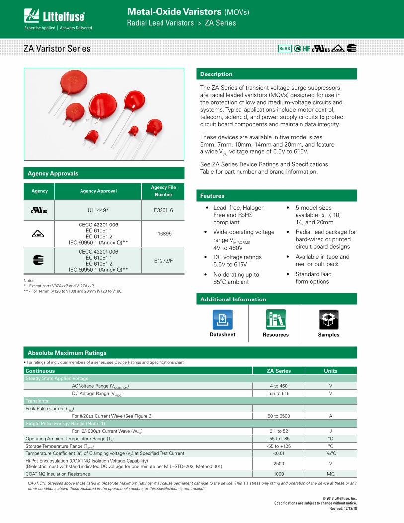
Description
The ZA Series of transient voltage surge suppressors are radial leaded varistors (MOVs) designed for use in the protection of low and medium-voltage circuits and systems. Typical applications include motor control, telecom, solenoid, and power supply circuits to protect circuit board components and maintain data integrity.
These devices are available in five model sizes: 5mm, 7mm, 10mm, 14mm and 20mm, and feature a wide VDC voltage range of 5.5V to 615V.
See ZA Series Device Ratings and Specifications Table for part number and brand information.
Features
• Lead–free, Halogen-Free and RoHS compliant
• Wide operating voltage range VM(AC)RMS 4V to 460V
• DC voltage ratings 5.5V to 615V
• No derating up to 85ºC ambient
• 5 model sizes available: 5, 7, 10, 14, and 20mm
• Radial lead package for hard-wired or printed circuit board designs
• Available in tape and reel or bulk pack
• Standard lead form options
Agency Approvals
Absolute Maximum Ratings• For ratings of individual members of a series, see Device Ratings and Specifications chart
Continuous ZA Series UnitsSteady State Applied Voltage:
AC Voltage Range (VM(AC)RMS) 4 to 460 V
DC Voltage Range (VM(DC)) 5.5 to 615 V
Transients:
Peak Pulse Current (ITM)
For 8/20µs Current Wave (See Figure 2) 50 to 6500 A
Single Pulse Energy Range (Note 1)
For 10/1000µs Current Wave (WTM) 0.1 to 52 J
Operating Ambient Temperature Range (TA) -55 to +85 ºC
Storage Temperature Range (TSTG) -55 to +125 ºC
Temperature Coefficient (aV) of Clamping Voltage (VC) at Specified Test Current <0.01 %/ºC
Hi-Pot Encapsulation (COATING Isolation Voltage Capability)(Dielectric must withstand indicated DC voltage for one minute per MIL–STD–202, Method 301) 2500 V
COATING Insulation Resistance 1000 MΩ
CAUTION: Stresses above those listed in "Absolute Maximum Ratings" may cause permanent damage to the device. This is a stress only rating and operation of the device at these or any other conditions above those indicated in the operational sections of this specification is not implied.
ZA Varistor Series RoHS
Additional Information
Datasheet SamplesResources
Agency Agency ApprovalAgency File
Number
UL1449* E320116
CECC 42201-006IEC 61051-1IEC 61051-2
IEC 60950-1 (Annex Q)**
116895
CECC 42201-006IEC 61051-1IEC 61051-2
IEC 60950-1 (Annex Q)**
E1273/F
Notes:* - Except parts V8ZAxxP and V12ZAxxP.** - For 14mm (V120 to V180) and 20mm (V120 to V180).
© 2018 Littelfuse, Inc.Specifications are subject to change without notice. Revised: 12/12/18
Metal-Oxide Varistors (MOVs)Radial Lead Varistors > ZA Series
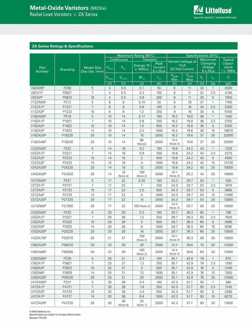
ZA Series Ratings & Specifications
Part Number Branding Model Size
Disc Dia. (mm)
Maximum Rating (85°C) Specifications (25°C)Continuous Transient
Varistor Voltage at 1mA
DC Test Current
Maximum Clamping Voltage 8 x 20µs
Typical Capaci-tance
f = 1MHzVRMS VDC
Energy 10 x 1000µs
Peak Current 8 x 20µs
VM(AC) VM(DC) WTM ITM VNOM Min
VNOM Max
VC IPK C
(V) (V) (J) (A) (V) (V) (V) (A) (pF)V8ZA05P PZ08 5 4 5.5 0.1 50 6 11 30 1 2000V8ZA1P P08Z1 7 4 5.5 0.4 100 6 11 22 2.5 4190V8ZA2P P08Z2 10 4 5.5 0.8 250 6 11 20 5 7000V12ZA05P PZ12 5 6 8 0.14 50 9 16 37 1 1700V12ZA1P P12Z1 7 6 8 0.6 100 9 16 34 2.5 3350V12ZA2P P12Z2 10 6 8 1.2 250 9 16 30 5 6100V18ZA05P PZ18 5 10 14 0.17 100 16.2 19.8 36 1 1400V18ZA1P P18Z1 7 10 14 0.8 250 16.2 19.8 36 2.5 2700V18ZA2P P18Z2 10 10 14 1.5 500 16.2 19.8 36 5 5300V18ZA3P P18Z3 14 10 14 3.5 1000 16.2 19.8 36 10 18870V18ZA20P P18Z20 20 10 14 10 2000 16.2 19.8 37 20 22000
V18ZA40P P18Z40 20 10 14 80 (Note2)
200016.2
(Note 3) 19.8 37 20 22000
V22ZA05P PZ22 5 14 18 0.2 100 19.8 24.2 43 1 1220V22ZA1P P22Z1 7 14 18 0.9 250 19.8 24.2 43 2.5 2375V22ZA2P P22Z2 10 14 18 2 500 19.8 24.2 43 5 4500V22ZA3P P22Z3 14 14 18 4 1000 19.8 24.2 43 10 14730V24ZA20P P24Z20 20 14 18 12 2000 19.8 24.2 43 20 18000
V24ZA50P P24Z50 20 14 18 (Note 4)
100(Note 2)
200020.7
(Note 3) 25.3 43 20 18000
V27ZA05P PZ27 5 17 22 0.25 100 24.3 29.7 53 1 920V27ZA1P P27Z1 7 17 22 1 250 24.3 29.7 53 2.5 1875V27ZA2P P27Z2 10 17 22 2.5 500 24.3 29.7 53 5 3850V27ZA4P P27Z4 14 17 22 5 1000 24.3 29.7 53 10 11480V27ZA20P P27Z20 20 17 22 14 2000 24.3 29.7 53 20 13000
V27ZA60P P27Z60 20 17 22 100 (Note 2) 200024.3
(Note 3) 29.7 50 20 13000
V33ZA05P PZ33 5 20 26 0.3 100 29.7 36.3 65 1 790V33ZA1P P33Z1 7 20 26 1.2 250 29.7 36.3 65 2.5 1620V33ZA2P P33Z2 10 20 26 3 500 29.7 36.3 65 5 3495V33ZA5P P33Z5 14 20 26 6 1000 29.7 36.3 65 10 9290V33ZA20P P33Z20 20 20 26 18 2000 29.7 36.3 65 20 13000
V33ZA70P P33Z70 20 21 27 100 (Note 2)
200029.7
(Note 3) 36.3 58 20 13000
V36ZA20P P36Z20 20 23 28 20 2000 32.4 39.6 70 20 12000
V36ZA80P P36Z80 20 23 28 100 (Note 2)
200032.4
(Note 3) 39.6 63 20 12000
V39ZA05P PZ39 5 25 31 0.3 100 35.1 42.9 79 1 675V39ZA1P P39Z1 7 25 31 1.2 250 35.1 42.9 79 2.5 1350V39ZA3P P39Z3 10 25 31 3 500 35.1 42.9 76 5 3100V39ZA6P P39Z6 14 25 31 7.2 1000 35.1 42.9 76 10 7000V39ZA20P P39Z20 20 25 31 20 2000 35.1 42.9 76 20 12000V47ZA05P PZ47 5 30 38 0.4 100 42.3 51.7 93 1 585V47ZA1P P47Z1 7 30 38 1.8 250 42.3 51.7 93 2.5 1245V47ZA3P P47Z3 10 30 38 4.5 500 42.3 51.7 93 5 2590V47ZA7P P47Z7 14 30 38 8.8 1000 42.3 51.7 93 10 6270
V47ZA20P P47Z20 20 30 38(Note 6)
23(Note 7)
2000 42.3 51.7 93 20 11000
© 2018 Littelfuse, Inc.Specifications are subject to change without notice.
Revised: 12/12/18
Metal-Oxide Varistors (MOVs)Radial Lead Varistors > ZA Series
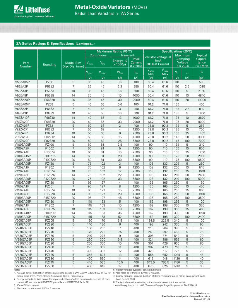
Part Number Branding Model Size
Disc Dia. (mm)
Maximum Rating (85°C) Specifications (25°C)Continuous Transient
Varistor Voltage at 1mA
DC Test Current
Maximum Clamping Voltage 8 x 20µs
Typical Capaci-tance
f = 1MHzVRMS VDC
Energy 10 x 1000µs
Peak Current 8 x 20µs
VM(AC) VM(DC) WTM ITM VNOM Min
VNOM Max
VC IPK C
(V) (V) (J) (A) (V) (V) (V) (A) (pF)V56ZA05P PZ56 5 35 45 0.5 100 50.4 61.6 110 1 500V56ZA2P P56Z2 7 35 45 2.3 250 50.4 61.6 110 2.5 1035V56ZA3P P56Z3 10 35 45 5.5 500 50.4 61.6 110 5 2150V56ZA8P P56Z8 14 35 45 10 1000 50.4 61.6 110 10 4840V56ZA20P P56Z20 20 35 45 30 2000 50.4 61.6 110 20 10000V68ZA05P PZ68 5 40 56 0.6 100 61.2 74.8 135 1 400V68ZA2P P68Z2 7 40 56 3 250 61.2 74.8 135 2.5 910V68ZA3P P68Z3 10 40 56 6.5 500 61.2 74.8 135 5 1850V68ZA10P P68Z10 14 40 56 13 1000 61.2 74.8 135 10 3870V68ZA20P P68Z20 20 40 56 33 2000 61.2 74.8 135 20 9000V82ZA05P PZ82 5 50 68 2 400 73.8 90.2 135 5 355V82ZA2P P82Z2 7 50 68 4 1200 73.8 90.2 135 10 700V82ZA4P P82Z4 10 50 68 8 2500 73.8 90.2 135 25 1485V82ZA12P P82Z12 14 50 68 15 4500 73.8 90.2 145 50 3380V82ZA20P P82Z20 20 50 68 25 6500 73.8 90.2 145 100 7000V100ZA05P PZ100 5 60 81 2.5 400 90 110 165 5 310V100ZA3P P100Z 7 60 81 5 1200 90 110 165 10 600V100ZA4P P100Z4 10 60 81 10 2500 90 110 165 25 1200V100ZA15P P100Z15 14 60 81 20 4500 90 110 175 50 2900V100ZA20P P100Z20 20 60 81 30 6500 90 110 175 100 6500V120ZA05P PZ120 5 75 102 3 400 108 132 205 5 250V120ZA1P P120Z 7 75 102 6 1200 108 132 205 10 515V120ZA4P P120Z4 10 75 102 12 2500 108 132 200 25 1100V120ZA6P P120Z6 14 75 102 22 4500 108 132 210 50 2450V120ZA20P P120Z20 20 75 102 33 6500 108 132 210 100 5000V150ZA05P PZ150 5 92 127 4 400 135 165 250 5 190V150ZA1P PZ051 7 95 127 8 1200 135 165 250 10 460V150ZA4P P150Z4 10 95 127 15 2500 135 165 250 25 860V150ZA8P P150Z8 14 95 127 20 4500 135 165 250 50 1910V150ZA20P P150Z20 20 95 127 45 6500 135 165 250 100 3500V180ZA05P PZ180 5 110 153 5 400 162 198 295 5 100V180ZA1P P180Z 7 115 153 10 1200 162 198 300 10 320V180ZA5P P180Z5 10 115 153 18 2500 162 198 300 25 465V180ZA10P P180Z10 14 115 153 35 4500 162 198 300 50 1190V180ZA20P P180Z20 20 115 153 52 6500 162 198 300 100 2400V205ZA05P PZ205 5 130 170 5.5 400 184.5 225.5 340 5 100V220ZA05P PZ220 5 140 180 6 400 198 242 360 5 95†V240ZA05P PZ240 5 150 200 7 400 216 264 395 5 90†V270ZA05P PZ270 5 175 225 7.5 400 243 297 455 5 75†V330ZA05P PZ330 5 210 275 9 400 306 374 540 5 70†V360ZA05P PZ360 5 230 300 9.5 400 324 396 595 5 60†V390ZA05P PZ390 5 250 330 10 400 351 429 650 5 80†V430ZA05P PZ430 5 275 369 11 400 387 473 710 5 75†V470ZA05P PZ470 5 300 385 12 400 423 517 775 5 70†V620ZA05P PZ620 5 385 505 13 400 558 682 1025 5 45†V680ZA05P PZ680 5 420 560 14 400 612 748 1120 5 40†V715ZA05P PZ715 5 440 585 15.5 400 643.5 786.5 1180 5 35†V750ZA05P PZ750 5 460 615 17 400 675 825 1240 5 30
ZA Series Ratings & Specifications (Continued...)
Note:1. Average power dissipation of transients not to exceed 0.2W, 0.25W, 0.4W, 0.6W or 1W for
model sizes 5mm, 7mm, 10mm, 14mm and 20mm, respectively.2. Energy rating (auto load dump) for impulse duration of 40ms minimum to one half of peak
current, 60 sec interval (ISO7637-2 pulse 5a and ISO16750-2 Table 5A)3. 10mA DC test current.4. Also rated to withstand 24V for 5 minutes.
5. Higher voltages available, contact Littelfuse.6. Also rated to withstand 48V for 5 minutes.7. Energy rating for impulse duration of 30ms minimum to one half of peak current (Auto
Load Dump): 100J8. The typical capacitance rating is the discrete component test result.† Also Recognized to UL 1449, Transient Voltage Surge Suppressors File E320116
© 2018 Littelfuse, Inc.Specifications are subject to change without notice. Revised: 12/12/18
Metal-Oxide Varistors (MOVs)Radial Lead Varistors > ZA Series
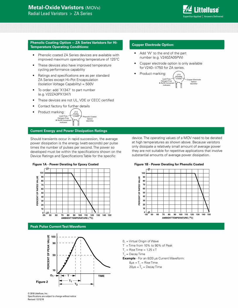
Should transients occur in rapid succession, the average power dissipation is the energy (watt-seconds) per pulse times the number of pulses per second. The power so developed must be within the specifications shown on the Device Ratings and Specifications Table for the specific
Current Energy and Power Dissipation Ratings
Peak Pulse Current Test Waveform
FIGURE 2. PEAK PULSE CURRENT TEST WAVEFORM
100
90
50
10
O1 T
T1T2
TIME
PE
RC
EN
T O
F P
EA
K V
AL
UE
O1 = Virtual Origin of WaveT = Time From 10% to 90% of Peak
T1 = Virtual Front time = 1.25 • tT2 = Virtual Time to Half Value (Impulse Duration)
Example: For an 8/20µs Current Waveform:8 s = T1 = Virtual Front Time
20 s = T2 = Virtual Time to Half Value
01 = Virtual Origin of WaveT = Time from 10% to 90% of PeakT1 = Rise Time = 1.25 x TT2 = Decay TimeExample - For an 8/20 µs Current Waveform:
8µs = T1 = Rise Time20µs = T2 = Decay Time
100
90
80
70
60
50
40
30
20
10
0-55 50 60 70 80 90 100 110 120 130 140 150
AMBIENT TEMPERATURE ( oC)
PE
RC
EN
T O
F R
ATE
D V
AL
UE
FIGURE 1. CURRENT, ENERGY AND POWER DERATING CURVE
Figure 1A - Power Derating for Epoxy Coated
Figure 2
FIGURE 1. CURRENT, ENERGY AND POWER DERATING CURVE
100
90
80
70
60
50
40
30
20
10
0-55 50 60 70 80 90 100 110 120 130 140 150
AMBIENT TEMPERATURE ( oC)
PE
RC
EN
T O
F R
ATE
D V
AL
UEdevice. The operating values of a MOV need to be derated at high temperatures as shown above. Because varistors only dissipate a relatively small amount of average power they are not suitable for repetitive applications that involve substantial amounts of average power dissipation.
Figure 1B - Power Derating for Phenolic Coated
• Phenolic coated ZA Series devices are available with improved maximum operating temperature of 125°C
• These devices also have improved temperature cycling performance capability
• Ratings and specifications are as per standard ZA Series except Hi–Pot Encapsulation (Isolation Voltage Capability) = 500V
• To order: add 'X1347' to part number (e.g. V22ZA3PX1347)
• These devices are not UL, VDE or CECC certified
• Contact factory for further details
• Product marking: LF 9P22P3YYWW Phenolic Coated
OptionIdentifier
Lead-Free,Halogen-Free
& RoHS CompliantIndicator
Phenolic Coating Option -- ZA Series Varistors for Hi-Temperature Operating Conditions:
Copper Electrode Option:
• Add 'W' to the end of the part number (e.g. V240ZA05PW)
• Copper electrode option is only available for V240~V750 for ZA series.
• Product marking: LF 9PZ240WYYWW Copper Electrode
OptionIdentifier
Lead-Free,Halogen-Free
& RoHS CompliantIndicator
© 2018 Littelfuse, Inc.Specifications are subject to change without notice.
Revised: 12/12/18
Metal-Oxide Varistors (MOVs)Radial Lead Varistors > ZA Series
V360ZA05(P) - V750ZA05(P)
FIGURE 5. CLAMPING VOLTAGE FOR V360ZA05(P) - V750ZA05(P) FIGURE 6. CLAMPING VOLTAGE FOR V8ZA1(P) - V68ZA2(P)
FIGURE 7. CLAMPING VOLTAGE FOR V82ZA2(P) - V180ZA1(P) FIGURE 8. CLAMPING VOLTAGE FOR V8ZA2(P) - V68ZA3(P)
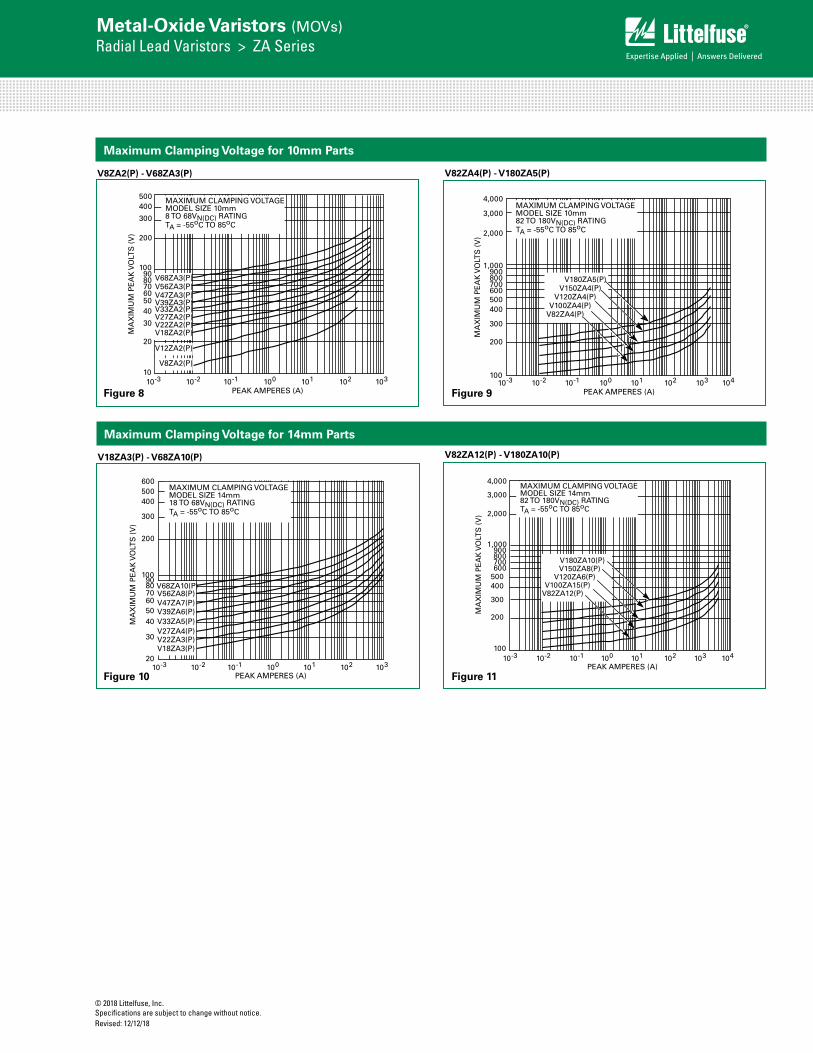
FIGURE 9. CLAMPING VOLTAGE FOR V82ZA4(P) - V180ZA5(P) FIGURE 10. CLAMPING VOLTAGE FOR V18ZA3(P) - V68ZA10(P)
3000
2000
1000
500
MA
XIM
UM
PE
AK
VO
LTS
(V
)
PEAK AMPERES (A)0.01 0.1 1 10 100 10000.0010.0001
V750ZA05(P)V715ZA05(P)V680ZA05(P)V620ZA05(P)V470ZA05(P)V430ZA05(P)V390ZA05(P)V360ZA05(P)
MAX CLAMPING VOLTAGE MODEL SIZE 5mm360 TO 750VN(DC) RATINGTA = -55oC TO 85oC
500400
300
200
100908070605040
30
20
10
MA
XIM
UM
PE
AK
VO
LTS
(V
)
10-3 10-2 10-1 100 101 102 103
MAXIMUM CLAMPING VOLTAGE
8 TO 68VN(DC) RATINGTA = -55oC TO 85oC
PEAK AMPERES (A)
V68ZA2(P)V56ZA2(P)V47ZA1(P)V39ZA1(P)V33ZA1(P)V27ZA1(P)V22ZA1(P)
V12ZA1(P)V18ZA1(P)
V8ZA1(P)
MODEL SIZE 7mm
MA
XIM
UM
PE
AK
VO
LTS
(V
)
PEAK AMPERES (A)10-2 10-1 100 101 102 10310-3
MAXIMUM CLAMPING VOLTAGE MODEL SIZE 7mm82 TO 180VN(DC) RATINGTA = -55oC TO 85oC
4,000
3,000
2,000
1,000900800700600500400
300
200
100104
V180ZA1(P)V150ZA1(P)
V120ZA1(P)V100ZA3(P)
V82ZA2(P)
500400
300
200
100908070605040
30
20
10
MA
XIM
UM
PE
AK
VO
LTS
(V
)
10-3 10-2 10-1 100 101 102 103
PEAK AMPERES (A)
V68ZA3(P)V56ZA3(P)V47ZA3(P)V39ZA3(P)V33ZA2(P)V27ZA2(P)V22ZA2(P)V18ZA2(P)
V8ZA2(P)
V12ZA2(P)
MAXIMUM CLAMPING VOLTAGE MODEL SIZE 10mm8 TO 68VN(DC) RATINGTA = -55oC TO 85oC
MA
XIM
UM
PE
AK
VO
LTS
(V
)
PEAK AMPERES (A)10-2 10-1 100 101 102 10310-3
MAXIMUM CLAMPING VOLTAGE MODEL SIZE 10mm82 TO 180VN(DC) RATINGTA = -55oC TO 85oC
4,000
3,000
2,000
1,000900800700600500400
300
200
100104
V180ZA5(P)V150ZA4(P)
V120ZA4(P)V100ZA4(P)
V82ZA4(P)
600500400
300
200
100908070605040
30
2010-3 10-2 10-1 100 101 102 103
PEAK AMPERES (A)
MA
XIM
UM
PE
AK
VO
LTS
(V
)
V68ZA10(P)V56ZA8(P)V47ZA7(P)V39ZA6(P)V33ZA5(P)V27ZA4(P)V22ZA3(P)V18ZA3(P)
MAXIMUM CLAMPING VOLTAGE
18 TO 68VN(DC) RATINGTA = -55oC TO 85oC
MODEL SIZE 14mm
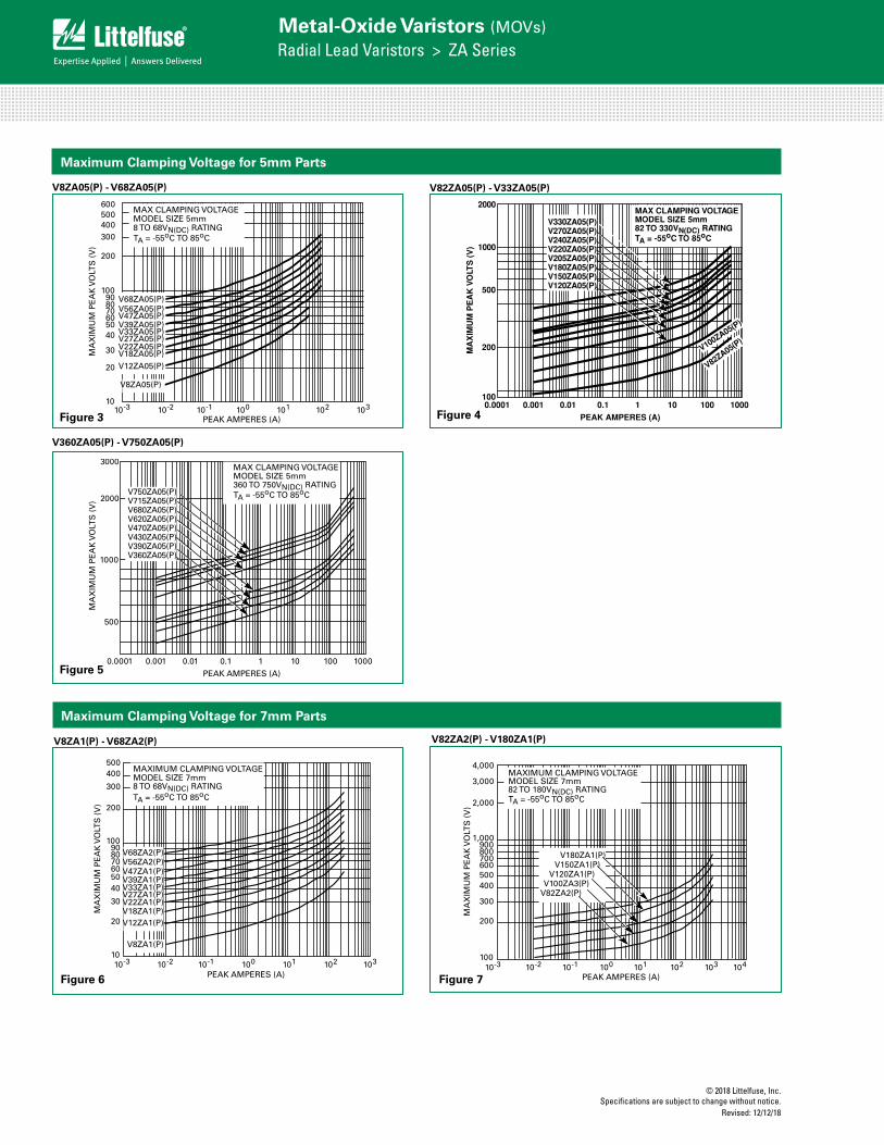
FIGURE 3. CLAMPING VOLTAGE FOR V8ZA05(P) - V68ZA05(P)
600500400300
200
100908070605040
30
20
MA
XIM
UM
PE
AK
VO
LTS
(V
)
PEAK AMPERES (A)10-2 10-1 100 101 102 103
MAX CLAMPING VOLTAGE MODEL SIZE 5mm8 TO 68VN(DC) RATINGTA = -55oC TO 85oC
10
V68ZA05(P)V56ZA05(P)V47ZA05(P)V39ZA05(P)V33ZA05(P)V27ZA05(P)V22ZA05(P)V18ZA05(P)V12ZA05(P)
V8ZA05(P)
10-3
Maximum Clamping Voltage for 5mm Parts
V8ZA05(P) - V68ZA05(P) V82ZA05(P) - V33ZA05(P)
FIGURE 4. CLAMPING VOLTAGE FOR V82ZA05(P) - V33ZA05(P)
2000
1000
500
200MA
XIM
UM
PE
AK
VO
LTS
(V
)
PEAK AMPERES (A)
0.01 0.1 1 10 100 1000100
0.0010.0001
V100ZA05(P)
V82ZA05(P)
MAX CLAMPING VOLTAGEMODEL SIZE 5mm82 TO 330VN(DC) RATINGTA = -55oC TO 85oC
V330ZA05(P)V270ZA05(P)V240ZA05(P)V220ZA05(P)V205ZA05(P)V180ZA05(P)V150ZA05(P)V120ZA05(P)
Figure 3 Figure 4
Figure 5
Maximum Clamping Voltage for 7mm Parts
V8ZA1(P) - V68ZA2(P) V82ZA2(P) - V180ZA1(P)
FIGURE 5. CLAMPING VOLTAGE FOR V360ZA05(P) - V750ZA05(P) FIGURE 6. CLAMPING VOLTAGE FOR V8ZA1(P) - V68ZA2(P)
FIGURE 7. CLAMPING VOLTAGE FOR V82ZA2(P) - V180ZA1(P) FIGURE 8. CLAMPING VOLTAGE FOR V8ZA2(P) - V68ZA3(P)
FIGURE 9. CLAMPING VOLTAGE FOR V82ZA4(P) - V180ZA5(P) FIGURE 10. CLAMPING VOLTAGE FOR V18ZA3(P) - V68ZA10(P)
3000
2000
1000
500
MA
XIM
UM
PE
AK
VO
LTS
(V
)
PEAK AMPERES (A)0.01 0.1 1 10 100 10000.0010.0001
V750ZA05(P)V715ZA05(P)V680ZA05(P)V620ZA05(P)V470ZA05(P)V430ZA05(P)V390ZA05(P)V360ZA05(P)
MAX CLAMPING VOLTAGE MODEL SIZE 5mm360 TO 750VN(DC) RATINGTA = -55oC TO 85oC
500400
300
200
100908070605040
30
20
10
MA
XIM
UM
PE
AK
VO
LTS
(V
)
10-3 10-2 10-1 100 101 102 103
MAXIMUM CLAMPING VOLTAGE
8 TO 68VN(DC) RATINGTA = -55oC TO 85oC
PEAK AMPERES (A)
V68ZA2(P)V56ZA2(P)V47ZA1(P)V39ZA1(P)V33ZA1(P)V27ZA1(P)V22ZA1(P)
V12ZA1(P)V18ZA1(P)
V8ZA1(P)
MODEL SIZE 7mm
MA
XIM
UM
PE
AK
VO
LTS
(V
)
PEAK AMPERES (A)10-2 10-1 100 101 102 10310-3
MAXIMUM CLAMPING VOLTAGE MODEL SIZE 7mm82 TO 180VN(DC) RATINGTA = -55oC TO 85oC
4,000
3,000
2,000
1,000900800700600500400
300
200
100104
V180ZA1(P)V150ZA1(P)
V120ZA1(P)V100ZA3(P)
V82ZA2(P)
500400
300
200
100908070605040
30
20
10
MA
XIM
UM
PE
AK
VO
LTS
(V
)
10-3 10-2 10-1 100 101 102 103
PEAK AMPERES (A)
V68ZA3(P)V56ZA3(P)V47ZA3(P)V39ZA3(P)V33ZA2(P)V27ZA2(P)V22ZA2(P)V18ZA2(P)
V8ZA2(P)
V12ZA2(P)
MAXIMUM CLAMPING VOLTAGE MODEL SIZE 10mm8 TO 68VN(DC) RATINGTA = -55oC TO 85oC
MA
XIM
UM
PE
AK
VO
LTS
(V
)
PEAK AMPERES (A)10-2 10-1 100 101 102 10310-3
MAXIMUM CLAMPING VOLTAGE MODEL SIZE 10mm82 TO 180VN(DC) RATINGTA = -55oC TO 85oC
4,000
3,000
2,000
1,000900800700600500400
300
200
100104
V180ZA5(P)V150ZA4(P)
V120ZA4(P)V100ZA4(P)
V82ZA4(P)
600500400
300
200
100908070605040
30
2010-3 10-2 10-1 100 101 102 103
PEAK AMPERES (A)
MA
XIM
UM
PE
AK
VO
LTS
(V
)
V68ZA10(P)V56ZA8(P)V47ZA7(P)V39ZA6(P)V33ZA5(P)V27ZA4(P)V22ZA3(P)V18ZA3(P)
MAXIMUM CLAMPING VOLTAGE
18 TO 68VN(DC) RATINGTA = -55oC TO 85oC
MODEL SIZE 14mm
Figure 6 Figure 7
© 2018 Littelfuse, Inc.Specifications are subject to change without notice. Revised: 12/12/18
Metal-Oxide Varistors (MOVs)Radial Lead Varistors > ZA Series
Maximum Clamping Voltage for 10mm Parts
V8ZA2(P) - V68ZA3(P)
Maximum Clamping Voltage for 14mm Parts
V82ZA4(P) - V180ZA5(P)
V18ZA3(P) - V68ZA10(P)
FIGURE 5. CLAMPING VOLTAGE FOR V360ZA05(P) - V750ZA05(P) FIGURE 6. CLAMPING VOLTAGE FOR V8ZA1(P) - V68ZA2(P)
FIGURE 7. CLAMPING VOLTAGE FOR V82ZA2(P) - V180ZA1(P) FIGURE 8. CLAMPING VOLTAGE FOR V8ZA2(P) - V68ZA3(P)
FIGURE 9. CLAMPING VOLTAGE FOR V82ZA4(P) - V180ZA5(P) FIGURE 10. CLAMPING VOLTAGE FOR V18ZA3(P) - V68ZA10(P)
3000
2000
1000
500
MA
XIM
UM
PE
AK
VO
LTS
(V
)
PEAK AMPERES (A)0.01 0.1 1 10 100 10000.0010.0001
V750ZA05(P)V715ZA05(P)V680ZA05(P)V620ZA05(P)V470ZA05(P)V430ZA05(P)V390ZA05(P)V360ZA05(P)
MAX CLAMPING VOLTAGE MODEL SIZE 5mm360 TO 750VN(DC) RATINGTA = -55oC TO 85oC
500400
300
200
100908070605040
30
20
10M
AX
IMU
M P
EA
K V
OLT
S (
V)
10-3 10-2 10-1 100 101 102 103
MAXIMUM CLAMPING VOLTAGE
8 TO 68VN(DC) RATINGTA = -55oC TO 85oC
PEAK AMPERES (A)
V68ZA2(P)V56ZA2(P)V47ZA1(P)V39ZA1(P)V33ZA1(P)V27ZA1(P)V22ZA1(P)
V12ZA1(P)V18ZA1(P)
V8ZA1(P)
MODEL SIZE 7mm
MA
XIM
UM
PE
AK
VO
LTS
(V
)
PEAK AMPERES (A)10-2 10-1 100 101 102 10310-3
MAXIMUM CLAMPING VOLTAGE MODEL SIZE 7mm82 TO 180VN(DC) RATINGTA = -55oC TO 85oC
4,000
3,000
2,000
1,000900800700600500400
300
200
100104
V180ZA1(P)V150ZA1(P)
V120ZA1(P)V100ZA3(P)
V82ZA2(P)
500400
300
200
100908070605040
30
20
10
MA
XIM
UM
PE
AK
VO
LTS
(V
)
10-3 10-2 10-1 100 101 102 103
PEAK AMPERES (A)
V68ZA3(P)V56ZA3(P)V47ZA3(P)V39ZA3(P)V33ZA2(P)V27ZA2(P)V22ZA2(P)V18ZA2(P)
V8ZA2(P)
V12ZA2(P)
MAXIMUM CLAMPING VOLTAGE MODEL SIZE 10mm8 TO 68VN(DC) RATINGTA = -55oC TO 85oC
MA
XIM
UM
PE
AK
VO
LTS
(V
)
PEAK AMPERES (A)10-2 10-1 100 101 102 10310-3
MAXIMUM CLAMPING VOLTAGE MODEL SIZE 10mm82 TO 180VN(DC) RATINGTA = -55oC TO 85oC
4,000
3,000
2,000
1,000900800700600500400
300
200
100104
V180ZA5(P)V150ZA4(P)
V120ZA4(P)V100ZA4(P)
V82ZA4(P)
600500400
300
200
100908070605040
30
2010-3 10-2 10-1 100 101 102 103
PEAK AMPERES (A)
MA
XIM
UM
PE
AK
VO
LTS
(V
)
V68ZA10(P)V56ZA8(P)V47ZA7(P)V39ZA6(P)V33ZA5(P)V27ZA4(P)V22ZA3(P)V18ZA3(P)
MAXIMUM CLAMPING VOLTAGE
18 TO 68VN(DC) RATINGTA = -55oC TO 85oC
MODEL SIZE 14mm
FIGURE 5. CLAMPING VOLTAGE FOR V360ZA05(P) - V750ZA05(P) FIGURE 6. CLAMPING VOLTAGE FOR V8ZA1(P) - V68ZA2(P)
FIGURE 7. CLAMPING VOLTAGE FOR V82ZA2(P) - V180ZA1(P) FIGURE 8. CLAMPING VOLTAGE FOR V8ZA2(P) - V68ZA3(P)
FIGURE 9. CLAMPING VOLTAGE FOR V82ZA4(P) - V180ZA5(P) FIGURE 10. CLAMPING VOLTAGE FOR V18ZA3(P) - V68ZA10(P)
3000
2000
1000
500
MA
XIM
UM
PE
AK
VO
LTS
(V
)
PEAK AMPERES (A)0.01 0.1 1 10 100 10000.0010.0001
V750ZA05(P)V715ZA05(P)V680ZA05(P)V620ZA05(P)V470ZA05(P)V430ZA05(P)V390ZA05(P)V360ZA05(P)
MAX CLAMPING VOLTAGE MODEL SIZE 5mm360 TO 750VN(DC) RATINGTA = -55oC TO 85oC
500400
300
200
100908070605040
30
20
10
MA
XIM
UM
PE
AK
VO
LTS
(V
)
10-3 10-2 10-1 100 101 102 103
MAXIMUM CLAMPING VOLTAGE
8 TO 68VN(DC) RATINGTA = -55oC TO 85oC
PEAK AMPERES (A)
V68ZA2(P)V56ZA2(P)V47ZA1(P)V39ZA1(P)V33ZA1(P)V27ZA1(P)V22ZA1(P)
V12ZA1(P)V18ZA1(P)
V8ZA1(P)
MODEL SIZE 7mm
MA
XIM
UM
PE
AK
VO
LTS
(V
)
PEAK AMPERES (A)10-2 10-1 100 101 102 10310-3
MAXIMUM CLAMPING VOLTAGE MODEL SIZE 7mm82 TO 180VN(DC) RATINGTA = -55oC TO 85oC
4,000
3,000
2,000
1,000900800700600500400
300
200
100104
V180ZA1(P)V150ZA1(P)
V120ZA1(P)V100ZA3(P)
V82ZA2(P)
500400
300
200
100908070605040
30
20
10
MA
XIM
UM
PE
AK
VO
LTS
(V
)
10-3 10-2 10-1 100 101 102 103
PEAK AMPERES (A)
V68ZA3(P)V56ZA3(P)V47ZA3(P)V39ZA3(P)V33ZA2(P)V27ZA2(P)V22ZA2(P)V18ZA2(P)
V8ZA2(P)
V12ZA2(P)
MAXIMUM CLAMPING VOLTAGE MODEL SIZE 10mm8 TO 68VN(DC) RATINGTA = -55oC TO 85oC
MA
XIM
UM
PE
AK
VO
LTS
(V
)
PEAK AMPERES (A)10-2 10-1 100 101 102 10310-3
MAXIMUM CLAMPING VOLTAGE MODEL SIZE 10mm82 TO 180VN(DC) RATINGTA = -55oC TO 85oC
4,000
3,000
2,000
1,000900800700600500400
300
200
100104
V180ZA5(P)V150ZA4(P)
V120ZA4(P)V100ZA4(P)
V82ZA4(P)
600500400
300
200
100908070605040
30
2010-3 10-2 10-1 100 101 102 103
PEAK AMPERES (A)
MA
XIM
UM
PE
AK
VO
LTS
(V
)
V68ZA10(P)V56ZA8(P)V47ZA7(P)V39ZA6(P)V33ZA5(P)V27ZA4(P)V22ZA3(P)V18ZA3(P)
MAXIMUM CLAMPING VOLTAGE
18 TO 68VN(DC) RATINGTA = -55oC TO 85oC
MODEL SIZE 14mmFIGURE 5. CLAMPING VOLTAGE FOR V360ZA05(P) - V750ZA05(P) FIGURE 6. CLAMPING VOLTAGE FOR V8ZA1(P) - V68ZA2(P)
FIGURE 7. CLAMPING VOLTAGE FOR V82ZA2(P) - V180ZA1(P) FIGURE 8. CLAMPING VOLTAGE FOR V8ZA2(P) - V68ZA3(P)
FIGURE 9. CLAMPING VOLTAGE FOR V82ZA4(P) - V180ZA5(P) FIGURE 10. CLAMPING VOLTAGE FOR V18ZA3(P) - V68ZA10(P)
3000
2000
1000
500
MA
XIM
UM
PE
AK
VO
LTS
(V
)
PEAK AMPERES (A)0.01 0.1 1 10 100 10000.0010.0001
V750ZA05(P)V715ZA05(P)V680ZA05(P)V620ZA05(P)V470ZA05(P)V430ZA05(P)V390ZA05(P)V360ZA05(P)
MAX CLAMPING VOLTAGE MODEL SIZE 5mm360 TO 750VN(DC) RATINGTA = -55oC TO 85oC
500400
300
200
100908070605040
30
20
10
MA
XIM
UM
PE
AK
VO
LTS
(V
)
10-3 10-2 10-1 100 101 102 103
MAXIMUM CLAMPING VOLTAGE
8 TO 68VN(DC) RATINGTA = -55oC TO 85oC
PEAK AMPERES (A)
V68ZA2(P)V56ZA2(P)V47ZA1(P)V39ZA1(P)V33ZA1(P)V27ZA1(P)V22ZA1(P)
V12ZA1(P)V18ZA1(P)
V8ZA1(P)
MODEL SIZE 7mm
MA
XIM
UM
PE
AK
VO
LTS
(V
)
PEAK AMPERES (A)10-2 10-1 100 101 102 10310-3
MAXIMUM CLAMPING VOLTAGE MODEL SIZE 7mm82 TO 180VN(DC) RATINGTA = -55oC TO 85oC
4,000
3,000
2,000
1,000900800700600500400
300
200
100104
V180ZA1(P)V150ZA1(P)
V120ZA1(P)V100ZA3(P)
V82ZA2(P)
500400
300
200
100908070605040
30
20
10
MA
XIM
UM
PE
AK
VO
LTS
(V
)
10-3 10-2 10-1 100 101 102 103
PEAK AMPERES (A)
V68ZA3(P)V56ZA3(P)V47ZA3(P)V39ZA3(P)V33ZA2(P)V27ZA2(P)V22ZA2(P)V18ZA2(P)
V8ZA2(P)
V12ZA2(P)
MAXIMUM CLAMPING VOLTAGE MODEL SIZE 10mm8 TO 68VN(DC) RATINGTA = -55oC TO 85oC
MA
XIM
UM
PE
AK
VO
LTS
(V
)
PEAK AMPERES (A)10-2 10-1 100 101 102 10310-3
MAXIMUM CLAMPING VOLTAGE MODEL SIZE 10mm82 TO 180VN(DC) RATINGTA = -55oC TO 85oC
4,000
3,000
2,000
1,000900800700600500400
300
200
100104
V180ZA5(P)V150ZA4(P)
V120ZA4(P)V100ZA4(P)
V82ZA4(P)
600500400
300
200
100908070605040
30
2010-3 10-2 10-1 100 101 102 103
PEAK AMPERES (A)
MA
XIM
UM
PE
AK
VO
LTS
(V
)
V68ZA10(P)V56ZA8(P)V47ZA7(P)V39ZA6(P)V33ZA5(P)V27ZA4(P)V22ZA3(P)V18ZA3(P)
MAXIMUM CLAMPING VOLTAGE
18 TO 68VN(DC) RATINGTA = -55oC TO 85oC
MODEL SIZE 14mm
V82ZA12(P) - V180ZA10(P)
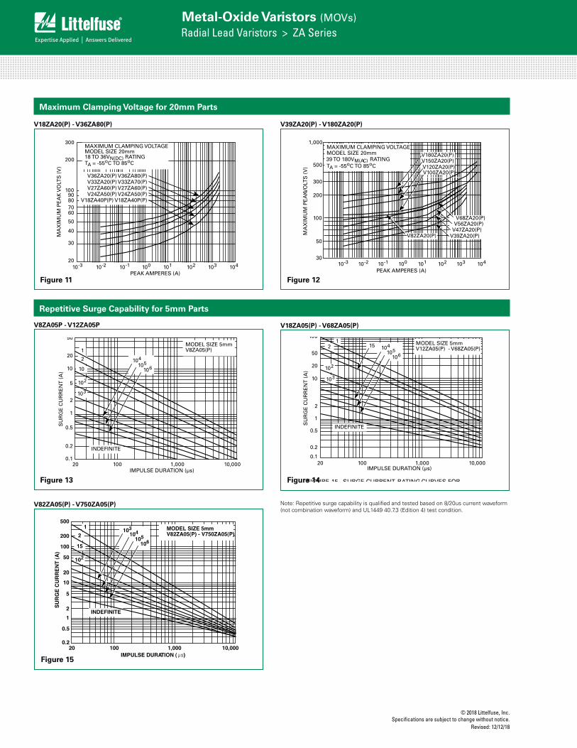
FIGURE 11. CLAMPING VOLTAGE FOR V82ZA12(P) - V180ZA10(P) FIGURE 12. CLAMPING VOLTAGE FOR V18ZA40(P) - V36ZA80(P)
FIGURE 13. CLAMPING VOLTAGE FOR V39ZA20(P) - V180ZA20(P)
Transient V-I Characteristic Curves (Continued)
PEAK AMPERES (A)10-2 10-1 100 101 102 10310-3
MAXIMUM CLAMPING VOLTAGE MODEL SIZE 14mm82 TO 180VN(DC) RATINGTA = -55oC TO 85oC
4,000
3,000
2,000
1,000900800700600
500400
300
200
100104
V180ZA10(P)V150ZA8(P)
V120ZA6(P)V100ZA15(P)
V82ZA12(P)
300
200
10090807060
50
40
30
20
MA
XIM
UM
PE
AK
VO
LTS
(V
)
MA
XIM
UM
PE
AK
VO
LTS
(V
)
PEAK AMPERES (A)10-2 10-1 100 101 102 10310-3 104
MAXIMUM CLAMPING VOLTAGE MODEL SIZE 20mm18 TO 36VN(DC) RATINGTA = -55oC TO 85oC
V36ZA20(P) V36ZA80(P)V33ZA20(P) V33ZA70(P)V27ZA60(P) V27ZA60(P)V24ZA50(P) V24ZA50(P)
V18ZA40P(P) V18ZA40P(P)
10-3 10-2 10-1 100 101 102 104103
1,000
500
300
200
30
PEAK AMPERES (A)
MA
XIM
UM
PE
AK
VO
LTS
(V
)
V56ZA20(P)V47ZA20(P)
V39ZA20(P)
MAXIMUM CLAMPING VOLTAGE MODEL SIZE 20mm
TA = -55oC TO 85oC39 TO 180VM(AC) RATING
V180ZA20(P)V150ZA20(P)V120ZA20(P)
100
50
V68ZA20(P)
Pulse Rating Curves
FIGURE 14. SURGE CURRENT RATING CURVES FOR V8ZA05(P) FIGURE 15. SURGE CURRENT RATING CURVES FOR V12ZA05(P) - V68ZA05(P)
50
20
10
5
2
1
0.5
0.2
0.1
SU
RG
E C
UR
RE
NT
(A
)
20 100 1,000 10,000IMPULSE DURATION (μs)
1
10
102
2
103
INDEFINITE
104105
106
MODEL SIZE 5mmV8ZA05(P)
100
50
20
10
2
1
0.5
0.2
0.1
SU
RG
E C
UR
RE
NT
(A
)
20 100 1,000 10,000
INDEFINITE
104105
106
MODEL SIZE 5mmV12ZA05(P) - V68ZA05(P)
115
102
2
103
IMPULSE DURATION (μs)
V82ZA20(P)
V100ZA20(P)
Figure 8 Figure 9
Figure 10 Figure 11
© 2018 Littelfuse, Inc.Specifications are subject to change without notice.
Revised: 12/12/18
Metal-Oxide Varistors (MOVs)Radial Lead Varistors > ZA Series
Maximum Clamping Voltage for 20mm Parts
V18ZA20(P) - V36ZA80(P)
Repetitive Surge Capability for 5mm Parts
V39ZA20(P) - V180ZA20(P)
V8ZA05P - V12ZA05P V18ZA05(P) - V68ZA05(P)
V82ZA05(P) - V750ZA05(P)
FIGURE 11. CLAMPING VOLTAGE FOR V82ZA12(P) - V180ZA10(P) FIGURE 12. CLAMPING VOLTAGE FOR V18ZA40(P) - V36ZA80(P)
FIGURE 13. CLAMPING VOLTAGE FOR V39ZA20(P) - V180ZA20(P)
Transient V-I Characteristic Curves (Continued)
PEAK AMPERES (A)10-2 10-1 100 101 102 10310-3
MAXIMUM CLAMPING VOLTAGE MODEL SIZE 14mm82 TO 180VN(DC) RATINGTA = -55oC TO 85oC
4,000
3,000
2,000
1,000900800700600
500400
300
200
100104
V180ZA10(P)V150ZA8(P)
V120ZA6(P)V100ZA15(P)
V82ZA12(P)
300
200
10090807060
50
40
30
20
MA
XIM
UM
PE
AK
VO
LTS
(V
)
MA
XIM
UM
PE
AK
VO
LTS
(V
)
PEAK AMPERES (A)10-2 10-1 100 101 102 10310-3 104
MAXIMUM CLAMPING VOLTAGE MODEL SIZE 20mm18 TO 36VN(DC) RATINGTA = -55oC TO 85oC
V36ZA20(P) V36ZA80(P)V33ZA20(P) V33ZA70(P)V27ZA60(P) V27ZA60(P)V24ZA50(P) V24ZA50(P)
V18ZA40P(P) V18ZA40P(P)
10-3 10-2 10-1 100 101 102 104103
1,000
500
300
200
30
PEAK AMPERES (A)
MA
XIM
UM
PE
AK
VO
LTS
(V
)
V56ZA20(P)V47ZA20(P)
V39ZA20(P)
MAXIMUM CLAMPING VOLTAGE MODEL SIZE 20mm
TA = -55oC TO 85oC39 TO 180VM(AC) RATING
V180ZA20(P)V150ZA20(P)V120ZA20(P)
100
50
V68ZA20(P)
Pulse Rating Curves
FIGURE 14. SURGE CURRENT RATING CURVES FOR V8ZA05(P) FIGURE 15. SURGE CURRENT RATING CURVES FOR V12ZA05(P) - V68ZA05(P)
50
20
10
5
2
1
0.5
0.2
0.1
SU
RG
E C
UR
RE
NT
(A
)
20 100 1,000 10,000IMPULSE DURATION (μs)
1
10
102
2
103
INDEFINITE
104105
106
MODEL SIZE 5mmV8ZA05(P)
100
50
20
10
2
1
0.5
0.2
0.1
SU
RG
E C
UR
RE
NT
(A
)
20 100 1,000 10,000
INDEFINITE
104105
106
MODEL SIZE 5mmV12ZA05(P) - V68ZA05(P)
115
102
2
103
IMPULSE DURATION (μs)
V82ZA20(P)
V100ZA20(P)
FIGURE 16. SURGE CURRENT RATING CURVES FOR V82ZA05(P) - V750ZA05(P)
FIGURE 17. SURGE CURRENT RATING CURVES FORV8ZA1(P) - V12ZA1(P)
FIGURE 18. SURGE CURRENT RATING CURVES FOR V18ZA1(P) - V68ZA2(P)
FIGURE 19. SURGE CURRENT RATING CURVES FOR V82ZA2(P) - V180ZA1(P)
FIGURE 20. SURGE CURRENT RATING CURVES FOR V8ZA2(P) - V127ZA2(P)
FIGURE 21. SURGE CURRENT RATING CURVES FOR V18ZA2(P) - V68ZA3(P)
50
20
10
5
2
1
0.5
0.2
SU
RG
E C
UR
RE
NT
(A
)
20 100 1,000 10,000IMPULSE DURATION (µs)
1
15
102
2103
INDEFINITE
104105
106
MODEL SIZE 5mmV82ZA05(P) - V750ZA05(P)
500
200
100
20 100 1,000 10,000IMPULSE DURATION (µs)
SU
RG
E C
UR
RE
NT
(A
)
1
10
102
2
103
INDEFINITE
104105
106
200
100
50
20
10
5
2
1
0.5
0.2
MODEL SIZE 7mmV8ZA1(P) - V12ZA1(P)
20 100 1,000 10,000IMPULSE DURATION (µs)
SU
RG
E C
UR
RE
NT
(A
)
1
10
102
2
103
INDEFINITE
500
200
100
50
20
10
2
1
0.5
0.2
104105
106
5
MODEL SIZE 7mmV18ZA1(P) - V68ZA2(P)
2,000
1,000
200
100
50
20
10
5
1
2
500
20 100 1,000 10,000IMPULSE DURATION (µs)
SU
RG
E C
UR
RE
NT
(A
)
1
2
10
102104
105
106
103
INDEFINITE
MODEL SIZE 7mmV82ZA2(P) - V180ZA1(P)
20 100 1,000 10,000IMPULSE DURATION (µs)
SU
RG
E C
UR
RE
NT
(A
)
1
10
102
2
103
INDEFINITE
500
200
100
50
20
10
2
1
0.5
0.2
104105
106
5
MODEL SIZE 10mmV8ZA2(P) - V12ZA2(P)
1,000
500
100
50
20
10
5
1
2
200
20
SU
RG
E C
UR
RE
NT
(A
)
1
2
105
106
104
INDEFINITE
MODEL SIZE 10mmV18ZA2(P) - V68ZA3(P)
100 1,000 10,000IMPULSE DURATION (µs)
102
103
Figure 11 Figure 12
Figure 13 Figure 14
Figure 15
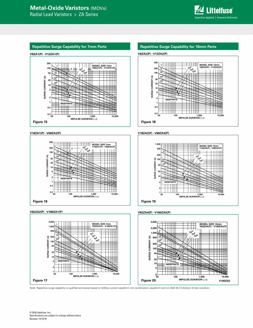
Note: Repetitive surge capability is qualified and tested based on 8/20us current waveform (not combination waveform) and UL1449 40.7.3 (Edition 4) test condition.
© 2018 Littelfuse, Inc.Specifications are subject to change without notice. Revised: 12/12/18
Metal-Oxide Varistors (MOVs)Radial Lead Varistors > ZA Series
Repetitive Surge Capability for 7mm Parts
V8ZA1(P) - V12ZA1(P)
V18ZA1(P) - V68ZA2(P)
FIGURE 16. SURGE CURRENT RATING CURVES FOR V82ZA05(P) - V750ZA05(P)
FIGURE 17. SURGE CURRENT RATING CURVES FORV8ZA1(P) - V12ZA1(P)
FIGURE 18. SURGE CURRENT RATING CURVES FOR V18ZA1(P) - V68ZA2(P)
FIGURE 19. SURGE CURRENT RATING CURVES FOR V82ZA2(P) - V180ZA1(P)
FIGURE 20. SURGE CURRENT RATING CURVES FOR V8ZA2(P) - V127ZA2(P)
FIGURE 21. SURGE CURRENT RATING CURVES FOR V18ZA2(P) - V68ZA3(P)
50
20
10
5
2
1
0.5
0.2
SU
RG
E C
UR
RE
NT
(A
)
20 100 1,000 10,000IMPULSE DURATION (µs)
1
10
102
2103
INDEFINITE
104105
106
MODEL SIZE 5mmV82ZA05(P) - V750ZA05(P)
500
200
100
20 100 1,000 10,000IMPULSE DURATION (µs)
SU
RG
E C
UR
RE
NT
(A
)
1
10
102
2
103
INDEFINITE
104105
106
200
100
50
20
10
5
2
1
0.5
0.2
MODEL SIZE 7mmV8ZA1(P) - V12ZA1(P)
20 100 1,000 10,000IMPULSE DURATION (µs)
SU
RG
E C
UR
RE
NT
(A
)
1
15
102
2
103
INDEFINITE
500
200
100
50
20
10
2
1
0.5
0.2
104105
106
5
MODEL SIZE 7mmV18ZA1(P) - V68ZA2(P)
2,000
1,000
200
100
50
20
10
5
1
2
500
20 100 1,000 10,000IMPULSE DURATION (µs)
SU
RG
E C
UR
RE
NT
(A
)
1
2
15
102104
105
106
103
INDEFINITE
MODEL SIZE 7mmV82ZA2(P) - V180ZA1(P)
20 100 1,000 10,000IMPULSE DURATION (µs)
SU
RG
E C
UR
RE
NT
(A
)
1
10
102
2
103
INDEFINITE
500
200
100
50
20
10
2
1
0.5
0.2
104105
106
5
MODEL SIZE 10mmV8ZA2(P) - V12ZA2(P)
1,000
500
100
50
20
10
5
1
2
200
20
SU
RG
E C
UR
RE
NT
(A
)
1
2
105
106
104
INDEFINITE
MODEL SIZE 10mmV18ZA2(P) - V68ZA3(P)
100 1,000 10,000IMPULSE DURATION (µs)
103
102
Repetitive Surge Capability for 10mm Parts
V82ZA2(P) - V180ZA1(P)
V8ZA2(P) - V12ZA2(P)
V18ZA2(P) - V68ZA3(P)
V82ZA4(P) - V180ZA5(P)FIGURE 16. SURGE CURRENT RATING CURVES FOR
V82ZA05(P) - V750ZA05(P) FIGURE 17. SURGE CURRENT RATING CURVES FOR
V8ZA1(P) - V12ZA1(P)
FIGURE 18. SURGE CURRENT RATING CURVES FOR V18ZA1(P) - V68ZA2(P)
FIGURE 19. SURGE CURRENT RATING CURVES FOR V82ZA2(P) - V180ZA1(P)
FIGURE 20. SURGE CURRENT RATING CURVES FOR V8ZA2(P) - V127ZA2(P)
FIGURE 21. SURGE CURRENT RATING CURVES FOR V18ZA2(P) - V68ZA3(P)
50
20
10
5
2
1
0.5
0.2
SU
RG
E C
UR
RE
NT
(A
)
20 100 1,000 10,000IMPULSE DURATION (µs)
1
10
102
2103
INDEFINITE
104105
106
MODEL SIZE 5mmV82ZA05(P) - V750ZA05(P)
500
200
100
20 100 1,000 10,000IMPULSE DURATION (µs)
SU
RG
E C
UR
RE
NT
(A
)
1
10
102
2
103
INDEFINITE
104105
106
200
100
50
20
10
5
2
1
0.5
0.2
MODEL SIZE 7mmV8ZA1(P) - V12ZA1(P)
20 100 1,000 10,000IMPULSE DURATION (µs)
SU
RG
E C
UR
RE
NT
(A
)
1
15
102
2
103
INDEFINITE
500
200
100
50
20
10
2
1
0.5
0.2
104105
106
5
MODEL SIZE 7mmV18ZA1(P) - V68ZA2(P)
2,000
1,000
200
100
50
20
10
5
1
2
500
20 100 1,000 10,000IMPULSE DURATION (µs)
SU
RG
E C
UR
RE
NT
(A
)
1
2
15
102104
105
106
103
INDEFINITE
MODEL SIZE 7mmV82ZA2(P) - V180ZA1(P)
20 100 1,000 10,000IMPULSE DURATION (µs)
SU
RG
E C
UR
RE
NT
(A
)
1
10
102
2
103
INDEFINITE
500
200
100
50
20
10
2
1
0.5
0.2
104105
106
5
MODEL SIZE 10mmV8ZA2(P) - V12ZA2(P)
1,000
500
100
50
20
10
5
1
2
200
20
SU
RG
E C
UR
RE
NT
(A
)
1
2
105
106
104
INDEFINITE
MODEL SIZE 10mmV18ZA2(P) - V68ZA3(P)
100 1,000 10,000IMPULSE DURATION (µs)
103
102
FIGURE 16. SURGE CURRENT RATING CURVES FOR V82ZA05(P) - V750ZA05(P)
FIGURE 17. SURGE CURRENT RATING CURVES FORV8ZA1(P) - V12ZA1(P)
FIGURE 18. SURGE CURRENT RATING CURVES FOR V18ZA1(P) - V68ZA2(P)
FIGURE 19. SURGE CURRENT RATING CURVES FOR V82ZA2(P) - V180ZA1(P)
FIGURE 20. SURGE CURRENT RATING CURVES FOR V8ZA2(P) - V127ZA2(P)
FIGURE 21. SURGE CURRENT RATING CURVES FOR V18ZA2(P) - V68ZA3(P)
50
20
10
5
2
1
0.5
0.2
SU
RG
E C
UR
RE
NT
(A
)
20 100 1,000 10,000IMPULSE DURATION (µs)
1
10
102
2103
INDEFINITE
104105
106
MODEL SIZE 5mmV82ZA05(P) - V750ZA05(P)
500
200
100
20 100 1,000 10,000IMPULSE DURATION (µs)
SU
RG
E C
UR
RE
NT
(A
)
1
10
102
2
103
INDEFINITE
104105
106
200
100
50
20
10
5
2
1
0.5
0.2
MODEL SIZE 7mmV8ZA1(P) - V12ZA1(P)
20 100 1,000 10,000IMPULSE DURATION (µs)
SU
RG
E C
UR
RE
NT
(A
)
1
15
102
2
103
INDEFINITE
500
200
100
50
20
10
2
1
0.5
0.2
104105
106
5
MODEL SIZE 7mmV18ZA1(P) - V68ZA2(P)
2,000
1,000
200
100
50
20
10
5
1
2
500
20 100 1,000 10,000IMPULSE DURATION (µs)
SU
RG
E C
UR
RE
NT
(A
)
1
2
15
102104
105
106
103
INDEFINITE
MODEL SIZE 7mmV82ZA2(P) - V180ZA1(P)
20 100 1,000 10,000IMPULSE DURATION (µs)
SU
RG
E C
UR
RE
NT
(A
)
1
10
102
2
103
INDEFINITE
500
200
100
50
20
10
2
1
0.5
0.2
104105
106
5
MODEL SIZE 10mmV8ZA2(P) - V12ZA2(P)
1,000
500
100
50
20
10
5
1
2
200
20
SU
RG
E C
UR
RE
NT
(A
)
1
2
105
106
104
INDEFINITE
MODEL SIZE 10mmV18ZA2(P) - V68ZA3(P)
100 1,000 10,000IMPULSE DURATION (µs)
103
102
FIGURE 22. SURGE CURRENT RATING CURVES FOR V82ZA4(P) - V180ZA5(P)
V180ZA5FIGURE 23. SURGE CURRENT RATING CURVES FOR
V18ZA3(P) - V68ZA10(P)
FIGURE 24. SURGE CURRENT RATING CURVES FOR V82ZA12(P) - V180ZA10(P)
FIGURE 25. SURGE CURRENT RATING CURRENT FOR V18ZA40(P) - V68ZA20(P)
FIGURE 26. SURGE CURRENT RATING CURVES FOR V120ZA20(P) - V180ZA20(P)
5,000
2,000
1,000
500
200
100
50
20
10
5
220 100 1,000 10,000
IMPULSE DURATION (µs)
SU
RG
E C
UR
RE
NT
(A
)
1
15
102
2
103
INDEFINITE
104105
106
MODEL SIZE 10mmV82ZA4(P) - V180ZA5(P)
200
100
50
20
10
5
1
2
20 100 1,000 10,000IMPULSE DURATION (µs)
SU
RG
E C
UR
RE
NT
(A
)
12
15
102
104
105
106
103
INDEFINITE
1,000
500MODEL SIZE 14mmV18ZA3(P) - V68ZA10(P)
5,000
2,000
200
100
50
20
10
5
2
500
20 100 1,000 10,000IMPULSE DURATION (µs)
SU
RG
E C
UR
RE
NT
(A
)
12
15
104
105
106
103
INDEFINITE
1,000 102
MODEL SIZE 14mmV82ZA12(P) - V180ZA10(P)
2,000
200
100
50
20
10
5
2
500
20 100 1,000 10,000IMPULSE DURATION (µs)
SU
RG
E C
UR
RE
NT
(A
)
12
101,000
102
103
104
105
106
INDEFINITE
MODEL SIZE 20mmV18ZA40(P) - V68ZA20(P)
10,0001,00010020
IMPULSE DURATION (µs)
SU
RG
E C
UR
RE
NT
(A
)
5,00010,000
2,000
500
100
20
10
2
1,000
200
50
1
5
12
10
102
103
104
105
106
INDEFINITE
MODEL SIZE 20mmV120ZA20(P) - V180ZA20(P)
Figure 15 Figure 18
Figure 16 Figure 19
Figure 17 Figure 20
Note: Repetitive surge capability is qualified and tested based on 8/20us current waveform (not combination waveform) and UL1449 40.7.3 (Edition 4) test condition.
© 2018 Littelfuse, Inc.Specifications are subject to change without notice.
Revised: 12/12/18
Metal-Oxide Varistors (MOVs)Radial Lead Varistors > ZA Series
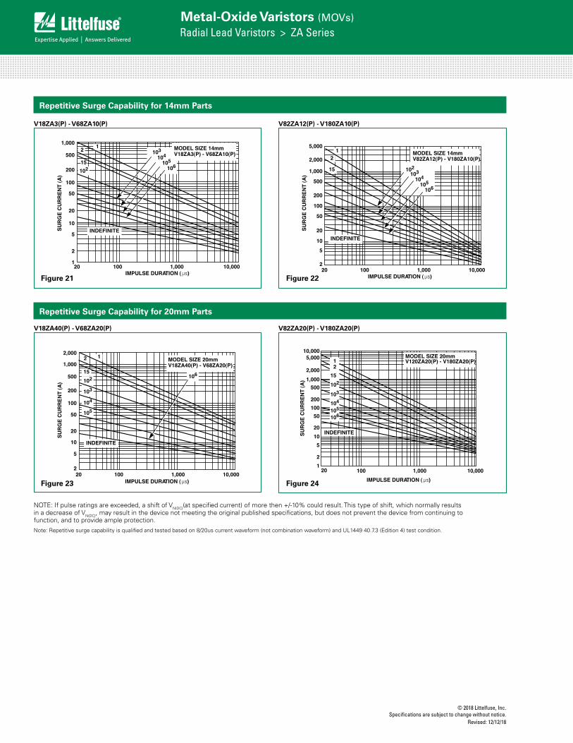
Repetitive Surge Capability for 14mm Parts
V18ZA3(P) - V68ZA10(P) V82ZA12(P) - V180ZA10(P)
FIGURE 22. SURGE CURRENT RATING CURVES FOR V82ZA4(P) - V180ZA5(P)
V180ZA5FIGURE 23. SURGE CURRENT RATING CURVES FOR
V18ZA3(P) - V68ZA10(P)
FIGURE 24. SURGE CURRENT RATING CURVES FOR V82ZA12(P) - V180ZA10(P)
FIGURE 25. SURGE CURRENT RATING CURRENT FOR V18ZA40(P) - V68ZA20(P)
FIGURE 26. SURGE CURRENT RATING CURVES FOR V120ZA20(P) - V180ZA20(P)
5,000
2,000
1,000
500
200
100
50
20
10
5
220 100 1,000 10,000
IMPULSE DURATION (µs)
SU
RG
E C
UR
RE
NT
(A
)
1
15
102
2
103
INDEFINITE
104105
106
MODEL SIZE 10mmV82ZA4(P) - V180ZA5(P)
200
100
50
20
10
5
1
2
20 100 1,000 10,000IMPULSE DURATION (µs)
SU
RG
E C
UR
RE
NT
(A
)
12
15
102
104
105
106
103
INDEFINITE
1,000
500MODEL SIZE 14mmV18ZA3(P) - V68ZA10(P)
5,000
2,000
200
100
50
20
10
5
2
500
20 100 1,000 10,000IMPULSE DURATION (µs)
SU
RG
E C
UR
RE
NT
(A
)
12
15
104
105
106
103
INDEFINITE
1,000 102
MODEL SIZE 14mmV82ZA12(P) - V180ZA10(P)
2,000
200
100
50
20
10
5
2
500
20 100 1,000 10,000IMPULSE DURATION (µs)
SU
RG
E C
UR
RE
NT
(A
)
12
101,000
102
103
104
105
106
INDEFINITE
MODEL SIZE 20mmV18ZA40(P) - V68ZA20(P)
10,0001,00010020
IMPULSE DURATION (µs)
SU
RG
E C
UR
RE
NT
(A
)
5,00010,000
2,000
500
100
20
10
2
1,000
200
50
1
5
12
10
102
103
104
105
106
INDEFINITE
MODEL SIZE 20mmV120ZA20(P) - V180ZA20(P)
FIGURE 24. SURGE CURRENT RATING CURVES FOR V82ZA12(P) - V180ZA10(P)
FIGURE 25. SURGE CURRENT RATING CURRENT FOR V18ZA40(P) - V68ZA20(P)
FIGURE 26. SURGE CURRENT RATING CURVES FOR V120ZA20(P) - V180ZA20(P)
5,000
2,000
200
100
50
20
10
5
2
500
20 100 1,000 10,000IMPULSE DURATION (µs)
SU
RG
E C
UR
RE
NT
(A
)
12
15
104
105
106
103
INDEFINITE
1,000 102
MODEL SIZE 14mmV82ZA12(P) - V180ZA10(P)
2,000
200
100
50
20
10
5
2
500
20 100 1,000 10,000IMPULSE DURATION (µs)
SU
RG
E C
UR
RE
NT
(A
)
12
151,000
102
103
104
105
106
INDEFINITE
MODEL SIZE 20mmV18ZA40(P) - V68ZA20(P)
10,0001,00010020
IMPULSE DURATION (µs)
SU
RG
E C
UR
RE
NT
(A
)
5,00010,000
2,000
500
100
20
10
2
1,000
200
50
1
5
12
15
102
103
104
105
106
INDEFINITE
MODEL SIZE 20mmV120ZA20(P) - V180ZA20(P)
V82ZA20(P) - V180ZA20(P)FIGURE 24. SURGE CURRENT RATING CURVES FOR V82ZA12(P) - V180ZA10(P)
FIGURE 25. SURGE CURRENT RATING CURRENT FOR V18ZA40(P) - V68ZA20(P)
FIGURE 26. SURGE CURRENT RATING CURVES FOR V120ZA20(P) - V180ZA20(P)
5,000
2,000
200
100
50
20
10
5
2
500
20 100 1,000 10,000IMPULSE DURATION (µs)
SU
RG
E C
UR
RE
NT
(A
)1
2
15
104
105
106
103
INDEFINITE
1,000 102
MODEL SIZE 14mmV82ZA12(P) - V180ZA10(P)
2,000
200
100
50
20
10
5
2
500
20 100 1,000 10,000IMPULSE DURATION (µs)
SU
RG
E C
UR
RE
NT
(A
)
12
151,000
102
103
104
105
106
INDEFINITE
MODEL SIZE 20mmV18ZA40(P) - V68ZA20(P)
10,0001,00010020
IMPULSE DURATION (µs)
SU
RG
E C
UR
RE
NT
(A
)
5,00010,000
2,000
500
100
20
10
2
1,000
200
50
1
5
12
15
102
103
104
105
106
INDEFINITE
MODEL SIZE 20mmV120ZA20(P) - V180ZA20(P)
V18ZA40(P) - V68ZA20(P)
FIGURE 24. SURGE CURRENT RATING CURVES FOR V82ZA12(P) - V180ZA10(P)
FIGURE 25. SURGE CURRENT RATING CURRENT FOR V18ZA40(P) - V68ZA20(P)
FIGURE 26. SURGE CURRENT RATING CURVES FOR V120ZA20(P) - V180ZA20(P)
5,000
2,000
200
100
50
20
10
5
2
500
20 100 1,000 10,000IMPULSE DURATION (µs)
SU
RG
E C
UR
RE
NT
(A
)
12
15
104
105
106
103
INDEFINITE
1,000 102
MODEL SIZE 14mmV82ZA12(P) - V180ZA10(P)
2,000
200
100
50
20
10
5
2
500
20 100 1,000 10,000IMPULSE DURATION (µs)
SU
RG
E C
UR
RE
NT
(A
)
12
151,000
102
103
104
105
106
INDEFINITE
MODEL SIZE 20mmV18ZA40(P) - V68ZA20(P)
10,0001,00010020
IMPULSE DURATION (µs)
SU
RG
E C
UR
RE
NT
(A
)
5,00010,000
2,000
500
100
20
10
2
1,000
200
50
1
5
12
15
102
103
104
105
106
INDEFINITE
MODEL SIZE 20mmV120ZA20(P) - V180ZA20(P)
NOTE: If pulse ratings are exceeded, a shift of VN(DC)(at specified current) of more then +/-10% could result. This type of shift, which normally results in a decrease of VN(DC), may result in the device not meeting the original published specifications, but does not prevent the device from continuing to function, and to provide ample protection.
Repetitive Surge Capability for 20mm Parts
Figure 21 Figure 22
Figure 23 Figure 24
Note: Repetitive surge capability is qualified and tested based on 8/20us current waveform (not combination waveform) and UL1449 40.7.3 (Edition 4) test condition.
© 2018 Littelfuse, Inc.Specifications are subject to change without notice. Revised: 12/12/18
Metal-Oxide Varistors (MOVs)Radial Lead Varistors > ZA Series
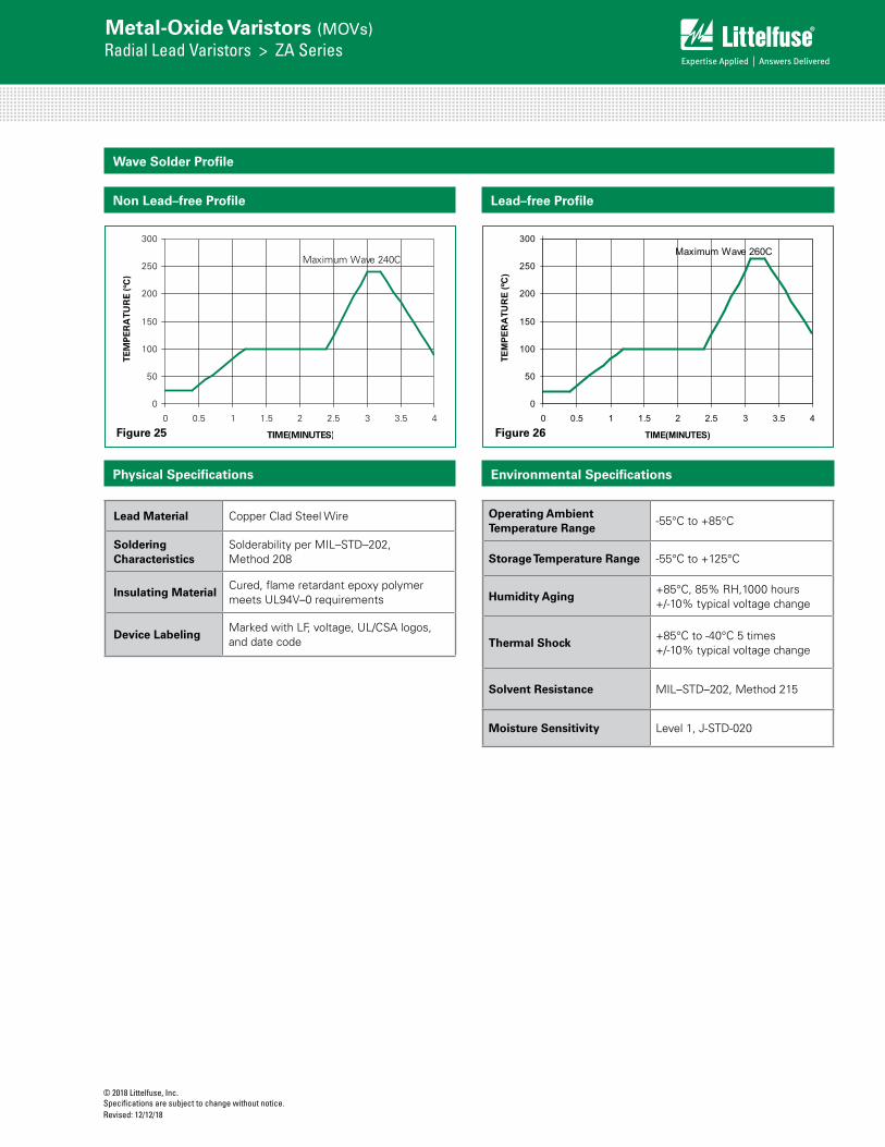
Operating Ambient Temperature Range
-55°C to +85°C
Storage Temperature Range -55°C to +125°C
Humidity Aging+85°C, 85% RH,1000 hours +/-10% typical voltage change
Thermal Shock+85°C to -40°C 5 times +/-10% typical voltage change
Solvent Resistance MIL–STD–202, Method 215
Moisture Sensitivity Level 1, J-STD-020
Lead Material Copper Clad Steel Wire
Soldering Characteristics
Solderability per MIL–STD–202, Method 208
Insulating MaterialCured, flame retardant epoxy polymer meets UL94V–0 requirements
Device LabelingMarked with LF, voltage, UL/CSA logos, and date code
Physical Specifications Environmental Specifications
Wave Solder Profile
0
50
100
150
200
250
300
0 0.5 1 1.5 2 2.5 3 3.5 4
TIME(MINUTES)
TEM
PE
RA
TUR
E (º
C)
Maximum Wave 240C
Lead–free Profile
0
50
100
150
200
250
300
0 0.5 1 1.5 2 2.5 3 3.5 4
TIME(MINUTES)
TEM
PER
ATU
RE
(ºC)
Maximum Wave 260C
Non Lead–free Profile
Figure 25 Figure 26
© 2018 Littelfuse, Inc.Specifications are subject to change without notice.
Revised: 12/12/18
Metal-Oxide Varistors (MOVs)Radial Lead Varistors > ZA Series
Product Dimensions (mm)
Dimen-sion
VRMS VoltageModel
5mm Size 7mm Size 10mm Size 14mm Size 20mm Size
Min. mm (in)
Max.mm (in)
Min. mm (in)
Max.mm (in)
Min.mm (in)
Max.mm (in)
Min.mm (in)
Max.mm (in)
Min.mm (in)
Max.mm (in)
A All - 10 (0.394) - 12 (0.472) - 16 (0.630) - 20 (0.787) - 26.5 (1.043)
ØD All - 7 (0.276) - 9 (0.354) - 12.5 (0.492) - 17 (0.669) - 23 (0.906)
e(see notes
below)All 4 (0.157) 6 (0.236) 4 (0.157) 6 (0.236) 6.5 (0.256) 8.5 (0.335) 6.5 (0.256) 8.5 (0.335) 6.5 (0.256)
(note 1 below) 8.5 (0.335) (note 1 below)
e1
V8ZA-V56ZA 1 (0.039) 3 (0.118) 1 (0.039) 3 (0.118) 1 (0.039) 3 (0.118) 1 (0.039) 3 (0.118) 1 (0.039) 3 (0.118)
V68ZA-V100ZA 1.5 (0.059) 3.5
(0.138) 1.5 (0.059) 3.5 (0.138) 1.5 (0.059) 3.5 (0.138) 1.5 (0.059) 3.5
(0.138) 1.5 (0.059) 3.5 (0.138)
V120ZA-V180ZA 1 (0.039) 3 (0.118) 1 (0.039) 3 (0.118) 1 (0.039) 3 (0.118) 1 (0.038) 3 (0.118) 1 (0.038) 3 (0.118)
V205ZA-V750ZA 1.5 (0.059) 3.5
(0.138) - - - - - - - -
E
V8ZA-V56ZA - 5 (0.197) - 5 (0.197) - 5 (0.197) - 5 (0.197) - 5 (0.197)
V68ZA-V100ZA - 5.6
(0.220) - 5.6 (0.220) - 5.6 (0.220) - 5.6
(0.220) - 5.6 (0.220)
V120ZA-V180ZA - 5 (0.197) - 5 (0.197) - 5 (0.197) - 5 (0.197) - 5 (0.197)
V205ZA-V750ZA - 5.6
(0.220) - - - - - - - -
Øb All 0.585 (0.023)
0.685 (0.027)
0.585 (0.023)
0.685 (0.027)
0.76 (0.030)
0.86 (0.034)
0.76 (0.030)
0.86 (0.034)
0.76 (0.030)
0.86 (0.034)
ATRIM All - 13.0 (0.512) - 15 (0.591) - 19.5 (0.768) - 22.5
(0.886) - 29.0 (1.142)
LTRIM All 2.41 (0.095)
4.69 (0.185)
2.41 (0.095)
4.69 (0.185)
2.41 (0.095)
4.69 (0.185)
2.41 (0.095)
4.69 (0.185)
2.41 (0.095)
4.69 (0.185)
1. For 20mm size devices, a 10mm "e" dimension option is also available. Please refer to "Ordering Notes" section "X10" option code for additional information.2. V24ZA50(P) and V24ZC50(P) only supplied with lead spacing of 6.35mm -/+0.5mm (0.25 -/+0.0196) Dimension e = 5.85 min. Does not apply to Tape and Reel parts.
NOTES: Dimensions in millimeters, inches in parentheses.
To order this crimped and trimmed lead style, standard radial type model numbers are changed by replacing the model letter "ZA" with "ZC." This option is supplied in bulk only.
Standard Model Order As
V18ZA3P V18ZC3P
For crimped leads without trimming and any varitions to the above, contact Littelfuse.
Example:
CRIMPED AND TRIMMED LEADRadial lead types can be supplied with combination preformed crimp and trimmed leads. This option is supplied to the dimensions shown.
*Seating plane interpretation per IEC-717LTRIM
ATRIM
SEATING PLANE
øD
øb25.4(1.00)MIN
A
ee1
E
© 2018 Littelfuse, Inc.Specifications are subject to change without notice. Revised: 12/12/18
Metal-Oxide Varistors (MOVs)Radial Lead Varistors > ZA Series
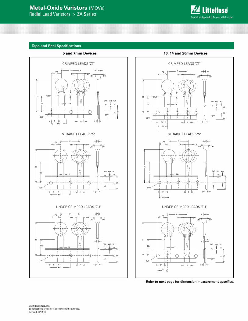
Tape and Reel Specifications
CRIMPED LEADS "ZT" CRIMPED LEADS "ZT"
Crimped Leads "ZT" Crimped Leads "ZT"
Straight Leads "ZS"Straight Leads "ZS"
Under-crimped Leads "ZU"
P1P0
E
DPDH DH
W1
W
F t
W2W0
P
DP
C
DbH0
DD0
H1SEATING PLANE
P2
P1
P0
W0
E
DPDH DH
W1
W
F t
W2
P
DP
C
DbH0
DD0
H1SEATING PLANE
P2
P0
DH
E
DHDP
W1
W
F t
W2
P
DP
DbH
DD0
H1
P1
P2
W0
P1P0
P2
DH
E
DHDP
W1
W
F t
W2W0
P
DP
DbH
DD0
H1
U
P1P0
P2
DH
E
DHDP
W1
W
F t
W2W0
P
DP
DbHo
DD0
H1
Under-crimped Leads "ZU"
P0
U
DH
E
DHDP
W1
W
F t
W2
P
DP
DbHo
DD0
H1
P2
W0
P1
UNDER CRIMPED LEADS "ZU" UNDER CRIMPED LEADS "ZU"
Crimped Leads "ZT" Crimped Leads "ZT"
Straight Leads "ZS"Straight Leads "ZS"
Under-crimped Leads "ZU"
P1P0
E
DPDH DH
W1
W
F t
W2W0
P
DP
C
DbH0
DD0
H1SEATING PLANE
P2
P1
P0
W0
E
DPDH DH
W1
W
F t
W2
P
DP
C
DbH0
DD0
H1SEATING PLANE
P2
P0
DH
E
DHDP
W1
W
F t
W2
P
DP
DbH
DD0
H1
P1
P2
W0
P1P0
P2
DH
E
DHDP
W1
W
F t
W2W0
P
DP
DbH
DD0
H1
U
P1P0
P2
DH
E
DHDP
W1
W
F t
W2W0
P
DP
DbHo
DD0
H1
Under-crimped Leads "ZU"
P0
U
DH
E
DHDP
W1
W
F t
W2
P
DP
DbHo
DD0
H1
P2
W0
P1
5 and 7mm Devices 10, 14 and 20mm Devices
STRAIGHT LEADS "ZS" STRAIGHT LEADS "ZS"
Refer to next page for dimension measurement specifics.
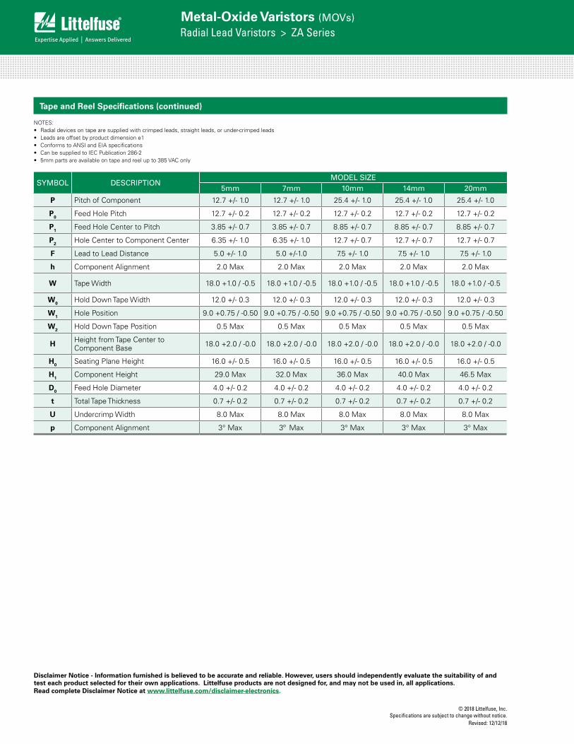
© 2018 Littelfuse, Inc.Specifications are subject to change without notice.
Revised: 12/12/18
Metal-Oxide Varistors (MOVs)Radial Lead Varistors > ZA Series
SYMBOL DESCRIPTION MODEL SIZE
5mm 7mm 10mm 14mm 20mm
P Pitch of Component 12.7 +/- 1.0 12.7 +/- 1.0 25.4 +/- 1.0 25.4 +/- 1.0 25.4 +/- 1.0
P0 Feed Hole Pitch 12.7 +/- 0.2 12.7 +/- 0.2 12.7 +/- 0.2 12.7 +/- 0.2 12.7 +/- 0.2
P1 Feed Hole Center to Pitch 3.85 +/- 0.7 3.85 +/- 0.7 8.85 +/- 0.7 8.85 +/- 0.7 8.85 +/- 0.7
P2 Hole Center to Component Center 6.35 +/- 1.0 6.35 +/- 1.0 12.7 +/- 0.7 12.7 +/- 0.7 12.7 +/- 0.7
F Lead to Lead Distance 5.0 +/- 1.0 5.0 +/-1.0 7.5 +/- 1.0 7.5 +/- 1.0 7.5 +/- 1.0
h Component Alignment 2.0 Max 2.0 Max 2.0 Max 2.0 Max 2.0 Max
W Tape Width 18.0 +1.0 / -0.5 18.0 +1.0 / -0.5 18.0 +1.0 / -0.5 18.0 +1.0 / -0.5 18.0 +1.0 / -0.5
W0 Hold Down Tape Width 12.0 +/- 0.3 12.0 +/- 0.3 12.0 +/- 0.3 12.0 +/- 0.3 12.0 +/- 0.3
W1 Hole Position 9.0 +0.75 / -0.50 9.0 +0.75 / -0.50 9.0 +0.75 / -0.50 9.0 +0.75 / -0.50 9.0 +0.75 / -0.50
W2 Hold Down Tape Position 0.5 Max 0.5 Max 0.5 Max 0.5 Max 0.5 Max
H Height from Tape Center to Component Base 18.0 +2.0 / -0.0 18.0 +2.0 / -0.0 18.0 +2.0 / -0.0 18.0 +2.0 / -0.0 18.0 +2.0 / -0.0
H0 Seating Plane Height 16.0 +/- 0.5 16.0 +/- 0.5 16.0 +/- 0.5 16.0 +/- 0.5 16.0 +/- 0.5
H1 Component Height 29.0 Max 32.0 Max 36.0 Max 40.0 Max 46.5 Max
D0 Feed Hole Diameter 4.0 +/- 0.2 4.0 +/- 0.2 4.0 +/- 0.2 4.0 +/- 0.2 4.0 +/- 0.2
t Total Tape Thickness 0.7 +/- 0.2 0.7 +/- 0.2 0.7 +/- 0.2 0.7 +/- 0.2 0.7 +/- 0.2
U Undercrimp Width 8.0 Max 8.0 Max 8.0 Max 8.0 Max 8.0 Max
p Component Alignment 3° Max 3º Max 3° Max 3° Max 3° Max
Tape and Reel Specifications (continued)
NOTES: • Radial devices on tape are supplied with crimped leads, straight leads, or under-crimped leads• Leads are offset by product dimension e1• Conforms to ANSI and EIA specifications• Can be supplied to IEC Publication 286-2• 5mm parts are available on tape and reel up to 385 VAC only
Disclaimer Notice - Information furnished is believed to be accurate and reliable. However, users should independently evaluate the suitability of and test each product selected for their own applications. Littelfuse products are not designed for, and may not be used in, all applications. Read complete Disclaimer Notice at www.littelfuse.com/disclaimer-electronics.
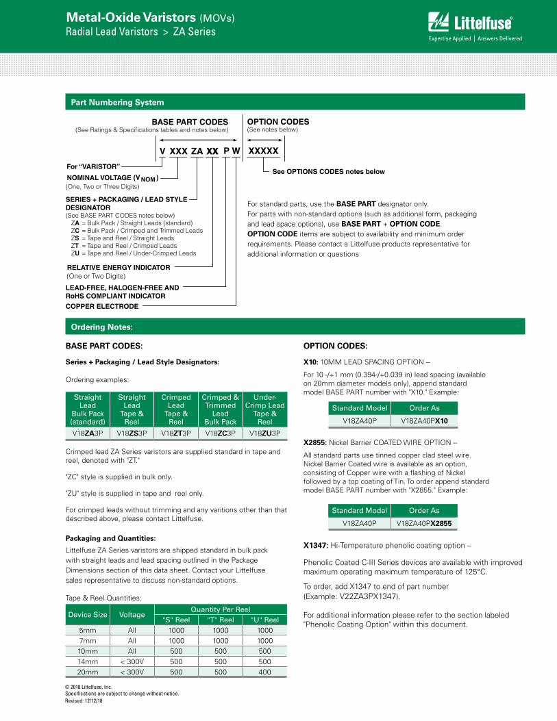
© 2018 Littelfuse, Inc.Specifications are subject to change without notice. Revised: 12/12/18
Metal-Oxide Varistors (MOVs)Radial Lead Varistors > ZA Series
Part Numbering System
For “VARISTOR”
NOMINAL VOLTAGE (VNOM )(One, Two or Three Digits)
V XXX ZA XXXX
RELATIVE ENERGY INDICATOR(One or Two Digits)
LEAD-FREE, HALOGEN-FREE AND RoHS COMPLIANT INDICATOR
P
See OPTIONS CODES notes below
XXXXX
OPTION CODES(See notes below)
BASE PART CODES(See Ratings & Specifications tables and notes below)
SERIES + PACKAGING / LEAD STYLEDESIGNATOR(See BASE PART CODES notes below)
ZA = Bulk Pack / Straight Leads (standard)ZC = Bulk Pack / Crimped and Trimmed Leads ZS = Tape and Reel / Straight Leads ZT = Tape and Reel / Crimped LeadsZU = Tape and Reel / Under-Crimped Leads
COPPER ELECTRODE
W
Ordering Notes:
Series + Packaging / Lead Style Designators:
Ordering examples:
Straight Lead
Bulk Pack(standard)
Straight Lead
Tape & Reel
Crimped Lead
Tape & Reel
Crimped & Trimmed
LeadBulk Pack
Under-Crimp Lead
Tape & Reel
V18ZA3P V18ZS3P V18ZT3P V18ZC3P V18ZU3P
Standard Model Order As
V18ZA40P V18ZA40PX10
Littelfuse ZA Series varistors are shipped standard in bulk pack with straight leads and lead spacing outlined in the Package Dimensions section of this data sheet. Contact your Littelfuse sales representative to discuss non-standard options.
Tape & Reel Quantities:
Crimped lead ZA Series varistors are supplied standard in tape and reel, denoted with "ZT."
"ZC" style is supplied in bulk only.
"ZU" style is supplied in tape and reel only.
For crimped leads without trimming and any varitions other than that described above, please contact Littelfuse.
Packaging and Quantities:
Device Size Voltage Quantity Per Reel
"S" Reel "T" Reel "U" Reel5mm All 1000 1000 10007mm All 1000 1000 100010mm All 500 500 50014mm < 300V 500 500 50020mm < 300V 500 500 400
For standard parts, use the BASE PART designator only. For parts with non-standard options (such as additional form, packaging and lead space options), use BASE PART + OPTION CODE. OPTION CODE items are subject to availability and minimum order requirements. Please contact a Littelfuse products representative for additional information or questions
BASE PART CODES: OPTION CODES:
Standard Model Order As
V18ZA40P V18ZA40PX2855
X10: 10MM LEAD SPACING OPTION --
For 10 -/+1 mm (0.394-/+0.039 in) lead spacing (available on 20mm diameter models only), append standard model BASE PART number with "X10." Example:
X2855: Nickel Barrier COATED WIRE OPTION --
All standard parts use tinned copper clad steel wire. Nickel Barrier Coated wire is available as an option, consisting of Copper wire with a flashing of Nickel followed by a top coating of Tin. To order append standard model BASE PART number with "X2855." Example:
X1347: Hi-Temperature phenolic coating option --
Phenolic Coated C-III Series devices are available with improved maximum operating maximum temperature of 125°C.
To order, add X1347 to end of part number (Example: V22ZA3PX1347).
For additional information please refer to the section labeled "Phenolic Coating Option" within this document.