metasys integrator simplex application application...
TRANSCRIPT
Issue Date April 1, 2005
© 2005 Johnson Controls, Inc. 1 Code No. LIT-6295440 www.johnsoncontrols.com Software Release 9.3
APPLICATION NOTE
Metasys Integrator® Simplex® Application
Introduction 3
Application Details 3 Network Configuration (NDU) 4 Component Requirements 6 Vendor Contact Information 8 Design Considerations 8
Cable Connections 11
Cable Pinouts 11 Connecting the Cable 12
Metasys Integrator Unit Setup 13
Point Mapping Tables 17
Simplex 4100/4100U/ 4120/4020 Master Controller 17 Simplex Network Interface Card 17 Simplex Network Interface Card Slot 18 Simplex Digital Pseudo Card 18 Simplex Four Point Auxiliary Relay Card, Eight Point Auxiliary Relay Card, and Eight Point Multi-function I/O Card 19 Simplex Auxiliary Relay Card and Multi-function Card Point Status Device Points 19 Simplex 4100U Transponder Interface Card (TIC) 20 Simplex 4100U SPS, Expansion Power Supply (XPS), Remote Power Supply (RPS), and the External Battery Charger (XBC) Card 20 Simplex 4100/40120 SPS, Expansion Power Supply (XPS), Remote Power Supply (RPS) and the External Battery Charger (XBC) Devices 21 Simplex 4100U IDnet Card 22 Simplex 4100U IDnet Devices 23
2 Metasys Integrator Simplex Application Application Note
Simplex Remote User Interface Card 24 Simplex Mapnet Interface Card 24 Simplex Mapnet II Device Points 25
Metasys Network Setup 26
Mapping to a CS Object 26
Custom Integration 27
Metasys Integrator Simplex Application Application Note 3
Introduction
This document explains Metasys Integrator® Simplex® 4100/4100U/4120/4020 Computer Port applications. Use this document with the Metasys Integrator unit technical bulletins, which provide information on installing and commissioning the Metasys Integrator unit. For information on Simplex equipment, see Simplex documentation (obtainable from a Simplex representative).
Note: If you use a Universal Packaging Module (UPM) enclosure, you must install the Metasys Integrator unit 300 Series in a two high enclosure (EN-EWC25-0) rather than a one high enclosure (EN-EWC13-0) as shown in the figures in this application note.
The Metasys Integrator unit is not Underwriters Laboratories Inc.® (UL) Listed as a fire alarm control unit (UOJZ). However, the Metasys Integrator unit is UL Listed as a smoke control accessory unit (UUKL) for smoke control applications. The Metasys Integrator unit is designed to provide secondary monitoring for a fire alarm, while the Simplex fire alarm control panels provide notification and control functions.
IMPORTANT: Do not use the Metasys Integrator unit as a primary fire alarm control unit. The Metasys Integrator unit provides secondary monitoring and can be used for smoke control applications. A fire alarm control panel is necessary to provide notification and alarm control functions. Use of the Metasys Integrator unit alone may result in a failure to obtain proper response to a fire with a resulting greater risk of property damage, personal injuries, or deaths.
The Metasys Integrator unit can connect to either a network of Simplex panels via a Simplex Network Display Unit (NDU), or to an individual panel. They cannot be combined on the same Metasys Integrator panel.
Application Details
Each Metasys Integrator vendor port can connect to one 4100/4100U/4120 or 4020 Computer Port.
Both the 4100U and NDU can support more data than one NCM can support. To ensure resonable performance, do not define more than 2,500 objects per NCM. Companion systems do not support more than 800 points.
4 Metasys Integrator Simplex Application Application Note
Be sure to define the card applications as well as the card devices. If not, devices can be offline and you may not receive any notification. This is true especially when the cause of the offline is a card failure. For the 4100U System Power Supply (SPS), define both the card status application for the SPS as well as the IDNet. The IDNet can exist both on the SPS card and as its own card.
IMPORTANT: Metasys Integrator unit supports reading analog values for the 4100U. These are read on a very slow poll and should not be used for fire alarm reporting but can provide warning alarms for preventative maintance.
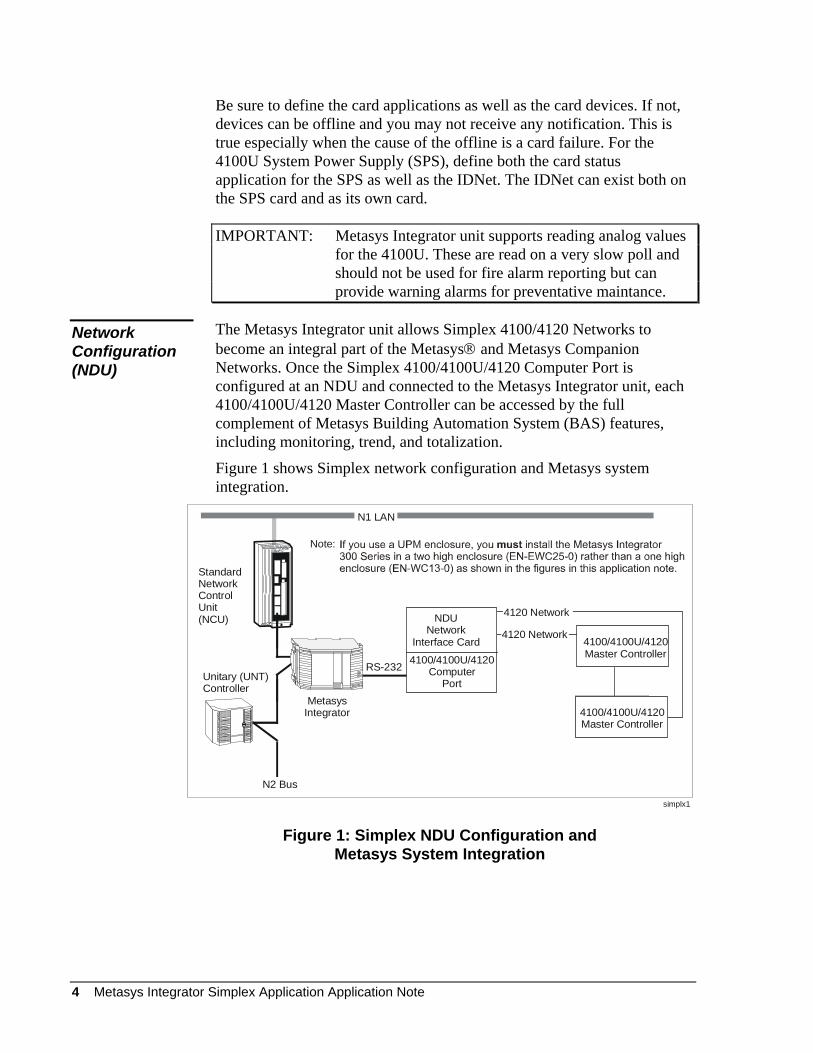
The Metasys Integrator unit allows Simplex 4100/4120 Networks to become an integral part of the Metasys® and Metasys Companion Networks. Once the Simplex 4100/4100U/4120 Computer Port is configured at an NDU and connected to the Metasys Integrator unit, each 4100/4100U/4120 Master Controller can be accessed by the full complement of Metasys Building Automation System (BAS) features, including monitoring, trend, and totalization.
Network Configuration (NDU)
Figure 1 shows Simplex network configuration and Metasys system integration.
N2 Bus
Standard NetworkControlUnit (NCU)
Unitary (UNT)Controller
RS-232
N1 LAN
MetasysIntegrator 4100/4120
Panel
4100/4100U/4120Master Controller
simplx1
NDUNetwork
Interface Card4100/4100U/4120
ComputerPort
4100/4100U/4120Master Controller
4120 Network
4120 Network
Note:
Figure 1: Simplex NDU Configuration and Metasys System Integration
Metasys Integrator Simplex Application Application Note 5
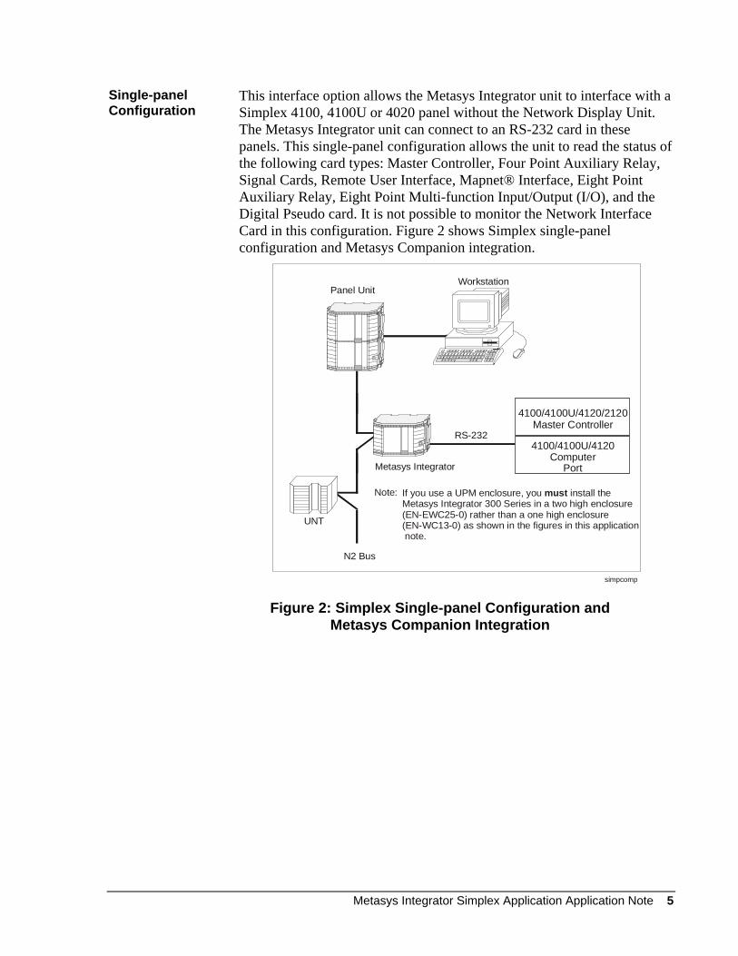
Single-panel Configuration
This interface option allows the Metasys Integrator unit to interface with a Simplex 4100, 4100U or 4020 panel without the Network Display Unit. The Metasys Integrator unit can connect to an RS-232 card in these panels. This single-panel configuration allows the unit to read the status of the following card types: Master Controller, Four Point Auxiliary Relay, Signal Cards, Remote User Interface, Mapnet® Interface, Eight Point Auxiliary Relay, Eight Point Multi-function Input/Output (I/O), and the Digital Pseudo card. It is not possible to monitor the Network Interface Card in this configuration. Figure 2 shows Simplex single-panel configuration and Metasys Companion integration.
N2 Bus
UNT
Metasys Integrator
simpcomp
RS-2324100/4100U/4120
ComputerPort
4100/4100U/4120/2120Master Controller
Panel UnitWorkstation
If you use a UPM enclosure, you install theMetasys Integrator 300 Series in a two high enclosure (EN-EWC25-0) rather than a one high enclosure(EN-WC13-0) as shown in the figures in this application note.
must Note:
Figure 2: Simplex Single-panel Configuration and Metasys Companion Integration
6 Metasys Integrator Simplex Application Application Note
Simplex Direct Connection
The direct connection interface option is used when it is not required to support the Network Interface Card. The statuses of the cards that are integrated to the local Simplex panel can be monitored. Use one or two N2 addresses for each card that is interfaced into the Metasys Integrator unit. Only one panel can be connected to a port on the Metasys Integrator unit.
Component Requirements Network Configuration (NDU)
To integrate Simplex equipment, you need:
• Simplex NDU
• Simplex Network Interface Card
• Simplex 4100/4100U/4120 Computer Port configured by a Simplex technical representative using the 4100 programming unit
• Simplex 4100/4100U/4120 Master Controller
• RS-232 cable for connecting the computer port to the Metasys Integrator unit (a Simplex RS-232 interface card is also required)
• Metasys Integrator unit
• N2 Bus (for connecting Metasys Integrator unit to the Metasys or Companion network)
• portable Personal Computer (PC) for downloading vendor communication tables (.VCT files) and network setup information into the Metasys Integrator unit, drive communication settings, and for running diagnostics
• cable for connecting portable PC to Metasys Integrator unit
• the correct vendor communication table (.VCT file) to download into the Metasys Integrator unit (supplied on the Metasys Integrator unit CD-ROM)
Metasys Integrator Simplex Application Application Note 7
Single-panel Configuration
To integrate Simplex equipment, you need:
• Simplex 4100/4100U/4120/4020 Computer Port configured by a Simplex technical representative using the 4100 programming unit
• Simplex 4100/4100U/4120/4020 Master Controller
• RS-232 cable for connecting the computer port to the Metasys Integrator unit (a Simplex RS-232 interface card is also required)
• Metasys Integrator unit
• N2 Bus (for connecting the Metasys Integrator unit to the Metasys or Companion network)
• portable PC for downloading vendor communication tables (.VCT files) and network setup information into the Metasys Integrator unit, drive communication settings, and for running diagnostics
• cable for connecting portable PC to the Metasys Integrator unit
• the correct vendor communication table (.VCT file) to download into the Metasys Integrator unit (supplied on CD-ROM)
This document describes the RS-232 cable and the vendor communication tables. Simplex documentation describes their equipment. The remaining components are described in the Metasys Integrator unit technical bulletins.
Metasys Network Release Requirements
To integrate Simplex equipment into the Metasys network, you need:
• Metasys Operator Workstation (OWS) software Release 9.01 or later
• Metasys Integrator unit firmware Release 9.01 or later
• Metasys Integrator unit software Release 9.3 or later
Metasys Companion Release Requirements
To integrate Simplex equipment into the Metasys Companion network, you need:
• Metasys Companion Release 6.0 or later
• Metasys Integrator unit firmware Release 9.01 or later
• Metasys Integrator unit software Release 9.3 or later
8 Metasys Integrator Simplex Application Application Note
Vendor Component Requirements
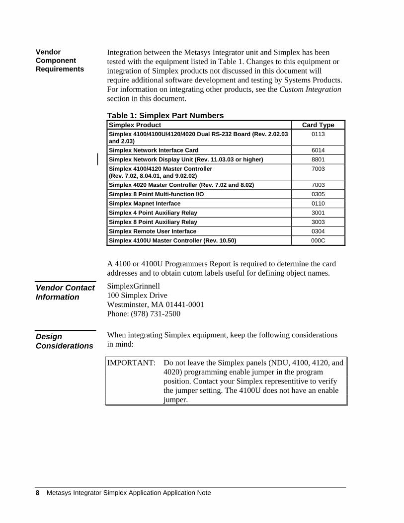
Integration between the Metasys Integrator unit and Simplex has been tested with the equipment listed in Table 1. Changes to this equipment or integration of Simplex products not discussed in this document will require additional software development and testing by Systems Products. For information on integrating other products, see the Custom Integration section in this document.
Table 1: Simplex Part Numbers Simplex Product Card Type Simplex 4100/4100U/4120/4020 Dual RS-232 Board (Rev. 2.02.03 and 2.03)
0113
Simplex Network Interface Card 6014 Simplex Network Display Unit (Rev. 11.03.03 or higher) 8801 Simplex 4100/4120 Master Controller (Rev. 7.02, 8.04.01, and 9.02.02)
7003
Simplex 4020 Master Controller (Rev. 7.02 and 8.02) 7003 Simplex 8 Point Multi-function I/O 0305 Simplex Mapnet Interface 0110 Simplex 4 Point Auxiliary Relay 3001 Simplex 8 Point Auxiliary Relay 3003 Simplex Remote User Interface 0304 Simplex 4100U Master Controller (Rev. 10.50) 000C
A 4100 or 4100U Programmers Report is required to determine the card addresses and to obtain cutom labels useful for defining object names.
SimplexGrinnell 100 Simplex Drive Westminster, MA 01441-0001 Phone: (978) 731-2500
Vendor Contact Information
When integrating Simplex equipment, keep the following considerations in mind:
Design Considerations
IMPORTANT: Do not leave the Simplex panels (NDU, 4100, 4120, and 4020) programming enable jumper in the program position. Contact your Simplex representitive to verify the jumper setting. The 4100U does not have an enable jumper.
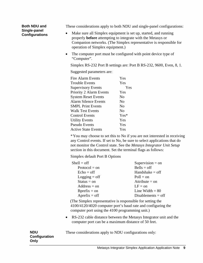
Both NDU and Single-panel Configurations
These considerations apply to both NDU and single-panel configurations:
• Make sure all Simplex equipment is set up, started, and running properly before attempting to integrate with the Metasys or Companion networks. (The Simplex representative is responsible for operation of Simplex equipment.)
• The computer port must be configured with point device type of “Computer”.
Simplex RS-232 Port B settings are: Port B RS-232, 9600, Even, 8, 1.
Suggested parameters are:
Fire Alarm Events Yes Trouble Events Yes Supervisory Events Yes Priority 2 Alarm Events Yes System Reset Events No Alarm Silence Events No SMPL Print Events No Walk Test Events No Control Events Yes* Utility Events Yes Pseudo Events Yes Active State Events Yes
* You may choose to set this to No if you are not interested in receiving any Control events. If set to No, be sure to select applications that do not monitor the Control state. See the Metasys Integrator Unit Setup section in this document. Set the terminal flags as follows:
Simplex default Port B Options
Shell = off Protocol = on Echo = off Logging = off Status = on Address = on Bprefix = on Aprefix = off
Supervision = on Bells = off Handshake = off Poll = on Attribute = on LF = on Line Width = 80 Disablements = off
(The Simplex representative is responsible for setting the 4100/4120/4020 computer port’s baud rate and configuring the computer port using the 4100 programming unit.)
• RS-232 cable distance between the Metasys Integrator unit and the computer port can be a maximum distance of 50 feet.
NDU Configuration Only
These considerations apply to NDU configurations only:
Metasys Integrator Simplex Application Application Note 9
• For optimal performance, make sure the Simplex representative configures the Network Display Unit database so that points are defined sequentially.
• The Simplex technical representative must configure a pseudo point for each node to indicate when a remote node is offline. When a remote node is offline, points mapped to the remote node will remain at their last reported value and status.
The Metasys Integrator unit maps Simplex 4100 System Point IDs to Network Point Addresses (NPAs). To convert a 4100 Network point shown in the 4100 Programming Unit job report to the 4100 System Point ID format (card-slot-point), do the following:
1. Determine the address of the Network Interface Card. This is the 4100 System Point ID card of the Point ID.
2. Calculate the 4100 System Point ID slot using the following calculation:
4100 System Point ID slot = ([4100 Network point* - 1]/256) + 1
3. Calculate the 4100 System Point ID point using the following calculation:
4100 System Point ID point = (4100 Network point* - 1) MOD 256, that is, the remainder of the division operation in Step 2.
4. Calculate the NPA:
NPA = 4100 System Point ID point + 1
*A 4100 Network point is a decimal number from 1-25,000.
Examples:
For the 4100 Network Point 257 on Network Interface Card Address 5, the 4100 System Point ID is 5-2-0. The corresponding Binary Input (BI) and Analog Data Integer (ADI) NPA is 1.
For the 4100 Network Point 1079 at Network Interface Card Address 1, the 4100 System Point ID is 1-5-54. The corresponding BI and ADI NPA is 55.
10 Metasys Integrator Simplex Application Application Note
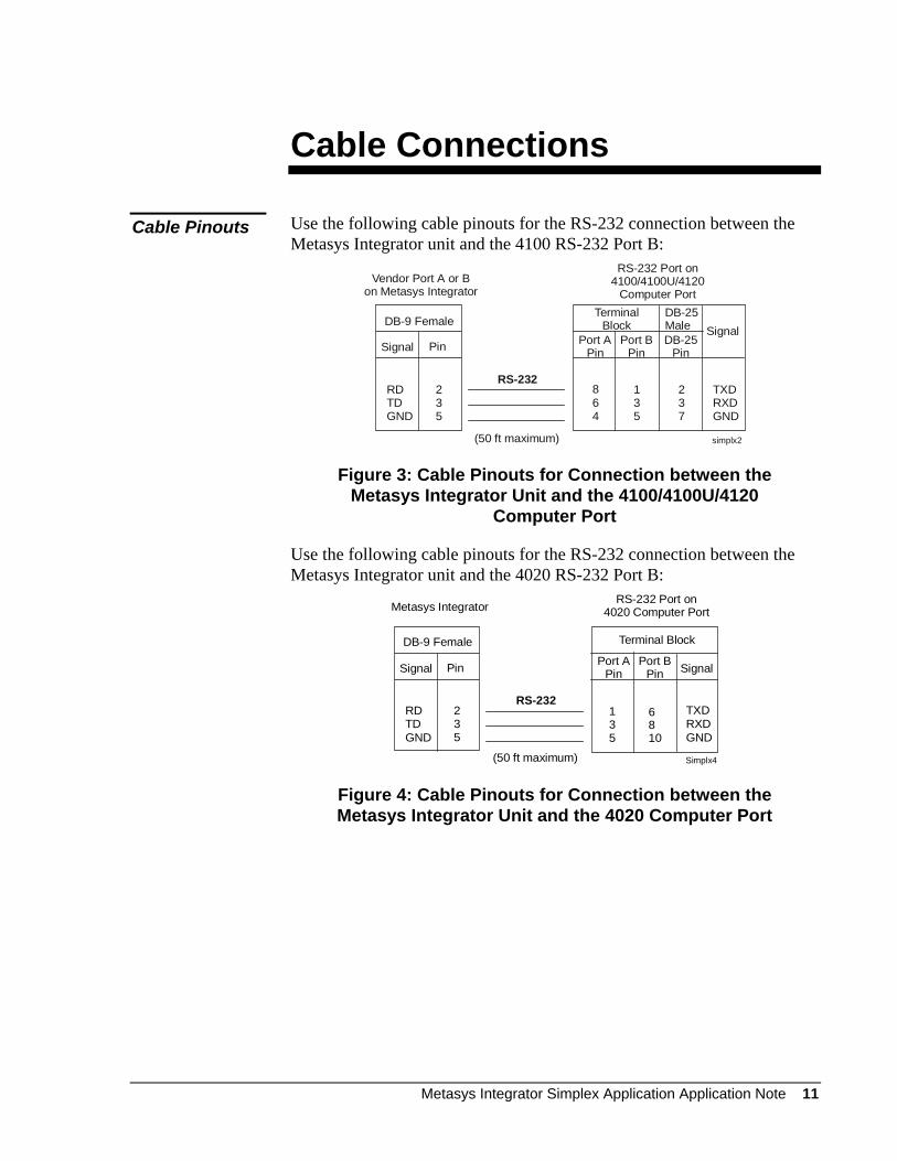
Cable Connections
Use the following cable pinouts for the RS-232 connection between the Metasys Integrator unit and the 4100 RS-232 Port B:
Cable Pinouts
Vendor Port A or Bon Metasys Integrator
simplx2(50 ft maximum)
DB-9 Female
Signal Pin
RDTDGND
235
DB-25Male Signal
Port APin
864
RS-232
RS-232 Port on4100/4100U/4120
Computer Port
TXDRXDGND
Port BPin
DB-25Pin
135
237
Terminal Block
Figure 3: Cable Pinouts for Connection between the Metasys Integrator Unit and the 4100/4100U/4120
Computer Port
Use the following cable pinouts for the RS-232 connection between the Metasys Integrator unit and the 4020 RS-232 Port B:
Metasys Integrator
Simplx4(50 ft maximum)
DB-9 Female
Signal Pin
RDTDGND
235
Terminal Block
SignalPort APin
RS-232
RS-232 Port on4020 Computer Port
TXDRXDGND
Port BPin
135
6810
Figure 4: Cable Pinouts for Connection between the Metasys Integrator Unit and the 4020 Computer Port
Metasys Integrator Simplex Application Application Note 11
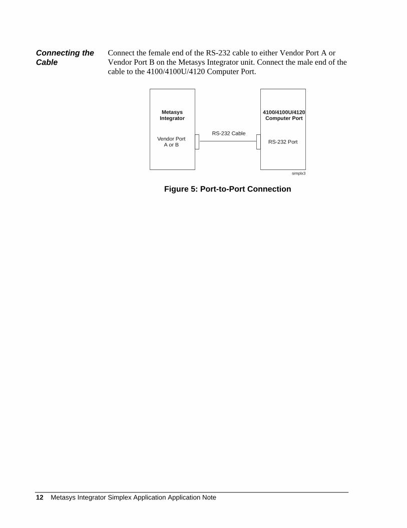
Connecting the Cable
Connect the female end of the RS-232 cable to either Vendor Port A or Vendor Port B on the Metasys Integrator unit. Connect the male end of the cable to the 4100/4100U/4120 Computer Port.
MetasysIntegrator
4100/4100U/4120Computer Port
RS-232 PortVendor PortA or B
RS-232 Cable
simplx3
Figure 5: Port-to-Port Connection
12 Metasys Integrator Simplex Application Application Note
Metasys Integrator Unit Setup
To set up a Metasys Integrator Network, use a portable PC connected to the Metasys Integrator Terminal Port. Metasys Integrator unit setup involves:
• downloading the correct vendor communication table (.VCT file)
• setting up the ports
• assigning network addresses to the controllers
The following table provides setup information specific to Simplex applications.
Metasys Integrator Simplex Application Application Note 13
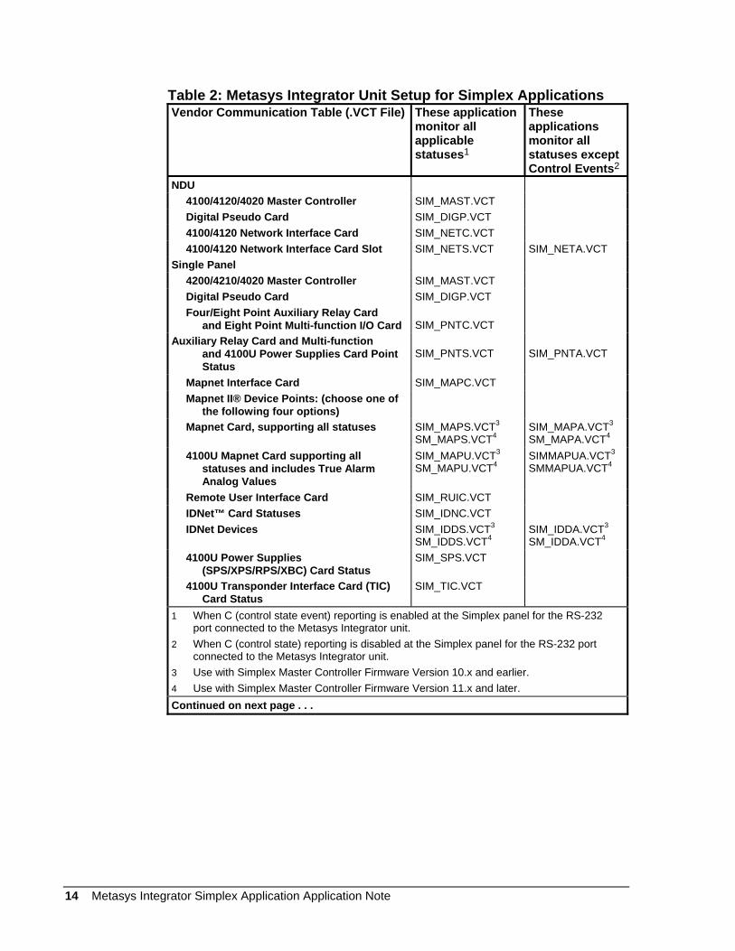
Table 2: Metasys Integrator Unit Setup for Simplex Applications Vendor Communication Table (.VCT File) These application
monitor all applicable statuses1
These applications monitor all statuses except Control Events2
NDU 4100/4120/4020 Master Controller SIM_MAST.VCT Digital Pseudo Card SIM_DIGP.VCT 4100/4120 Network Interface Card SIM_NETC.VCT 4100/4120 Network Interface Card Slot SIM_NETS.VCT SIM_NETA.VCT Single Panel 4200/4210/4020 Master Controller SIM_MAST.VCT Digital Pseudo Card SIM_DIGP.VCT Four/Eight Point Auxiliary Relay Card and Eight Point Multi-function I/O Card
SIM_PNTC.VCT
Auxiliary Relay Card and Multi-function and 4100U Power Supplies Card Point Status
SIM_PNTS.VCT
SIM_PNTA.VCT
Mapnet Interface Card SIM_MAPC.VCT Mapnet II® Device Points: (choose one of the following four options)
Mapnet Card, supporting all statuses SIM_MAPS.VCT3 SM_MAPS.VCT4
SIM_MAPA.VCT3
SM_MAPA.VCT4
4100U Mapnet Card supporting all statuses and includes True Alarm Analog Values
SIM_MAPU.VCT3 SM_MAPU.VCT4
SIMMAPUA.VCT3 SMMAPUA.VCT4
Remote User Interface Card SIM_RUIC.VCT IDNet™ Card Statuses SIM_IDNC.VCT IDNet Devices SIM_IDDS.VCT3
SM_IDDS.VCT4SIM_IDDA.VCT3 SM_IDDA.VCT4
4100U Power Supplies (SPS/XPS/RPS/XBC) Card Status
SIM_SPS.VCT
4100U Transponder Interface Card (TIC) Card Status
SIM_TIC.VCT
1 When C (control state event) reporting is enabled at the Simplex panel for the RS-232 port connected to the Metasys Integrator unit.
2 When C (control state) reporting is disabled at the Simplex panel for the RS-232 port connected to the Metasys Integrator unit.
3 Use with Simplex Master Controller Firmware Version 10.x and earlier. 4 Use with Simplex Master Controller Firmware Version 11.x and later. Continued on next page . . .
14 Metasys Integrator Simplex Application Application Note
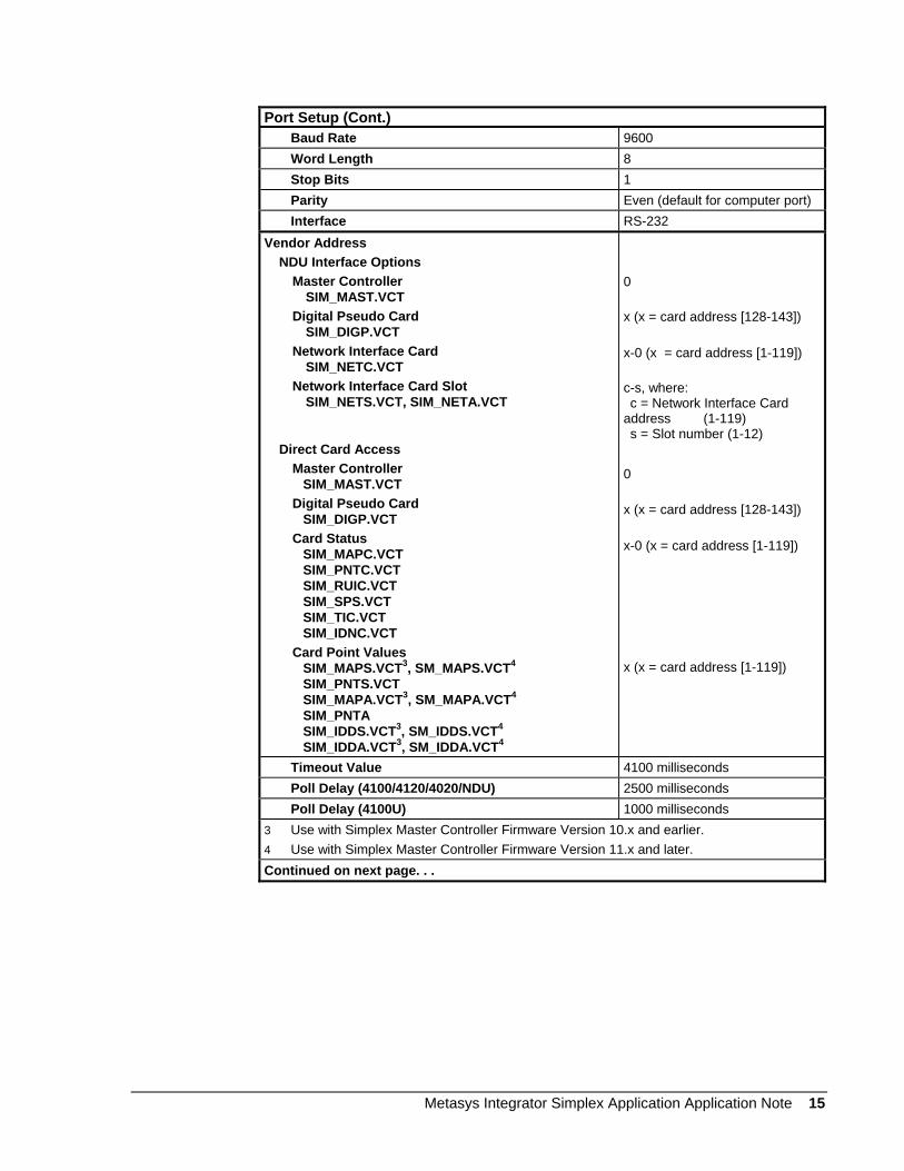
Port Setup (Cont.) Baud Rate 9600 Word Length 8 Stop Bits 1 Parity Even (default for computer port) Interface RS-232 Vendor Address NDU Interface Options Master Controller SIM_MAST.VCT Digital Pseudo Card SIM_DIGP.VCT Network Interface Card SIM_NETC.VCT Network Interface Card Slot SIM_NETS.VCT, SIM_NETA.VCT Direct Card Access Master Controller SIM_MAST.VCT Digital Pseudo Card SIM_DIGP.VCT Card Status SIM_MAPC.VCT SIM_PNTC.VCT SIM_RUIC.VCT SIM_SPS.VCT SIM_TIC.VCT SIM_IDNC.VCT Card Point Values SIM_MAPS.VCT3, SM_MAPS.VCT4 SIM_PNTS.VCT SIM_MAPA.VCT3, SM_MAPA.VCT4 SIM_PNTA SIM_IDDS.VCT3, SM_IDDS.VCT4 SIM_IDDA.VCT3, SM_IDDA.VCT4
0 x (x = card address [128-143]) x-0 (x = card address [1-119]) c-s, where: c = Network Interface Card address (1-119) s = Slot number (1-12) 0 x (x = card address [128-143]) x-0 (x = card address [1-119]) x (x = card address [1-119])
Timeout Value 4100 milliseconds Poll Delay (4100/4120/4020/NDU) 2500 milliseconds Poll Delay (4100U) 1000 milliseconds 3 Use with Simplex Master Controller Firmware Version 10.x and earlier. 4 Use with Simplex Master Controller Firmware Version 11.x and later. Continued on next page. . .
Metasys Integrator Simplex Application Application Note 15
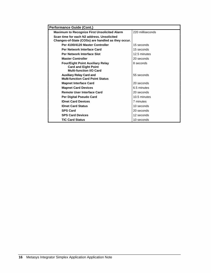
Performance Guide (Cont.) Maximum to Recognize First Unsolicited Alarm 220 milliseconds Scan time for each N2 address. Unsolicited
Changes-of-State (COSs) are handled as they occur.
Per 4100/4120 Master Controller 15 seconds Per Network Interface Card 15 seconds Per Network Interface Slot 12.5 minutes Master Controller 20 seconds Four/Eight Point Auxiliary Relay
Card and Eight Point Multi-function I/O Card
8 seconds
Auxiliary Relay Card and Multi-function Card Point Status
55 seconds
Mapnet Interface Card 20 seconds Mapnet Card Devices 6.5 minutes Remote User Interface Card 20 seconds Per Digital Pseudo Card 10.5 minutes IDnet Card Devices 7 minutes IDnet Card Status 10 seconds SPS Card 20 seconds SPS Card Devices 12 seconds TIC Card Status 10 seconds
16 Metasys Integrator Simplex Application Application Note
Point Mapping Tables
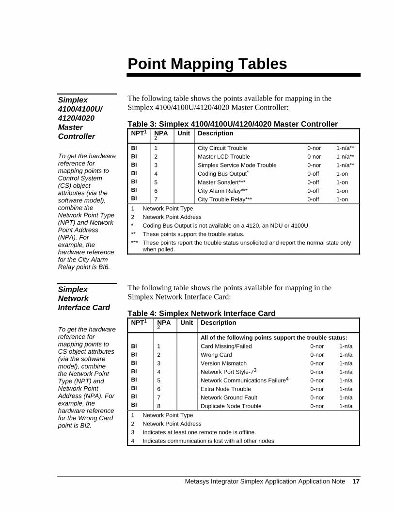
The following table shows the points available for mapping in the Simplex 4100/4100U/4120/4020 Master Controller:
Simplex 4100/4100U/ 4120/4020 Master Controller To get the hardware reference for mapping points to Control System (CS) object attributes (via the software model), combine the Network Point Type (NPT) and Network Point Address (NPA). For example, the hardware reference for the City Alarm Relay point is BI6.
Table 3: Simplex 4100/4100U/4120/4020 Master Controller NPT1 NPA
2 Unit Description
BI BI BI BI BI BI BI
1 2 3 4 5 6 7
City Circuit Trouble 0-nor 1-n/a** Master LCD Trouble 0-nor 1-n/a** Simplex Service Mode Trouble 0-nor 1-n/a** Coding Bus Output* 0-off 1-on Master Sonalert*** 0-off 1-on City Alarm Relay*** 0-off 1-on City Trouble Relay*** 0-off 1-on
1 Network Point Type 2 Network Point Address * Coding Bus Output is not available on a 4120, an NDU or 4100U. ** These points support the trouble status. *** These points report the trouble status unsolicited and report the normal state only
when polled.
The following table shows the points available for mapping in the Simplex Network Interface Card:
Simplex Network Interface Card To get the hardware reference for mapping points to CS object attributes (via the software model), combine the Network Point Type (NPT) and Network Point Address (NPA). For example, the hardware reference for the Wrong Card point is BI2.
Table 4: Simplex Network Interface Card NPT1 NPA
2 Unit Description
All of the following points support the trouble status: BI BI BI BI BI BI BI BI
1 2 3 4 5 6 7 8
Card Missing/Failed 0-nor 1-n/a Wrong Card 0-nor 1-n/a Version Mismatch 0-nor 1-n/a Network Port Style-73 0-nor 1-n/a Network Communications Failure4 0-nor 1-n/a Extra Node Trouble 0-nor 1-n/a Network Ground Fault 0-nor 1-n/a Duplicate Node Trouble 0-nor 1-n/a
1 Network Point Type 2 Network Point Address 3 Indicates at least one remote node is offline. 4 Indicates communication is lost with all other nodes.
Metasys Integrator Simplex Application Application Note 17
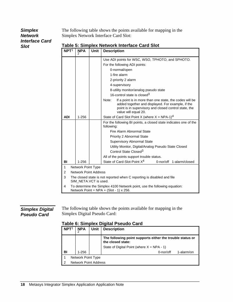
Simplex Network Interface Card Slot
The following table shows the points available for mapping in the Simplex Network Interface Card Slot:
Table 5: Simplex Network Interface Card Slot NPT1 NPA
2 Unit Description
Use ADI points for WSC, WSO, TPHOTO, and SPHOTO. For the following ADI points: 0-normal/open 1-fire alarm 2-priority 2 alarm 4-supervisory 8-utility monitor/analog pseudo state 16-control state is closed3 Note: If a point is in more than one state, the codes will be
added together and displayed. For example, if the point is in supervisory and closed control state, the value will equal 20.
ADI 1-256 State of Card Slot Point X (where X = NPA-1)4 For the following BI points, a closed state indicates one of the
following: Fire Alarm Abnormal State Priority 2 Abnormal State Supervisory Abnormal State Utility Monitor, Digital/Analog Pseudo State Closed Control State Closed3 All of the points support trouble status.
BI 1-256 State of Card-Slot-Point X4 0-nor/off 1-alarm/closed 1 Network Point Type 2 Network Point Address 3 The closed state is not reported when C reporting is disabled and file
SIM_NETA.VCT is used. 4 To determine the Simplex 4100 Network point, use the following equation:
Network Point = NPA + (Slot - 1) x 256.
The following table shows the points available for mapping in the Simplex Digital Pseudo Card:
Simplex Digital Pseudo Card
Table 6: Simplex Digital Pseudo Card NPT1 NPA
2 Unit Description
The following point supports either the trouble status or the closed state:
BI
1-256
State of Digital Point (where X = NPA - 1) 0-nor/off 1-alarm/on
1 Network Point Type 2 Network Point Address
18 Metasys Integrator Simplex Application Application Note
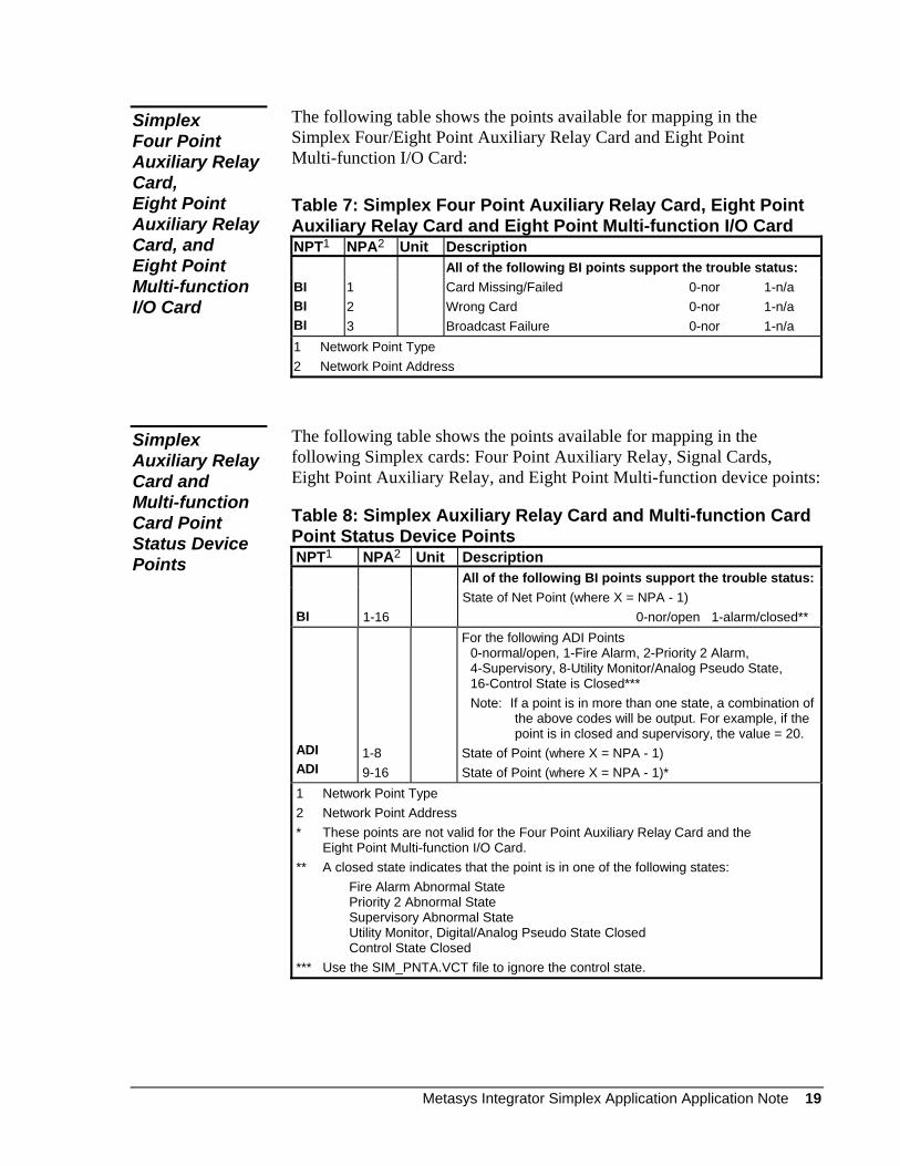
The following table shows the points available for mapping in the Simplex Four/Eight Point Auxiliary Relay Card and Eight Point Multi-function I/O Card:
Simplex Four Point Auxiliary Relay Card, Eight Point Auxiliary Relay Card, and Eight Point Multi-function I/O Card
Table 7: Simplex Four Point Auxiliary Relay Card, Eight Point Auxiliary Relay Card and Eight Point Multi-function I/O Card NPT1 NPA2 Unit Description All of the following BI points support the trouble status: BI BI BI
1 2 3
Card Missing/Failed 0-nor 1-n/a Wrong Card 0-nor 1-n/a Broadcast Failure 0-nor 1-n/a
1 Network Point Type 2 Network Point Address
The following table shows the points available for mapping in the following Simplex cards: Four Point Auxiliary Relay, Signal Cards, Eight Point Auxiliary Relay, and Eight Point Multi-function device points:
Simplex Auxiliary Relay Card and Multi-function Card Point Status Device Points
Table 8: Simplex Auxiliary Relay Card and Multi-function Card Point Status Device Points NPT1 NPA2 Unit Description All of the following BI points support the trouble status: BI
1-16
State of Net Point (where X = NPA - 1) 0-nor/open 1-alarm/closed**
ADI ADI
1-8 9-16
For the following ADI Points 0-normal/open, 1-Fire Alarm, 2-Priority 2 Alarm, 4-Supervisory, 8-Utility Monitor/Analog Pseudo State, 16-Control State is Closed*** Note: If a point is in more than one state, a combination of
the above codes will be output. For example, if the point is in closed and supervisory, the value = 20.
State of Point (where X = NPA - 1) State of Point (where X = NPA - 1)*
1 Network Point Type 2 Network Point Address * These points are not valid for the Four Point Auxiliary Relay Card and the
Eight Point Multi-function I/O Card. ** A closed state indicates that the point is in one of the following states: Fire Alarm Abnormal State
Priority 2 Abnormal State Supervisory Abnormal State Utility Monitor, Digital/Analog Pseudo State Closed Control State Closed
*** Use the SIM_PNTA.VCT file to ignore the control state.
Metasys Integrator Simplex Application Application Note 19
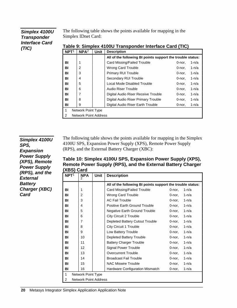
The following table shows the points available for mapping in the Simplex IDnet Card:
Simplex 4100U Transponder Interface Card (TIC) Table 9: Simplex 4100U Transponder Interface Card (TIC)
NPT1 NPA2 Unit Description All of the following BI points support the trouble status: BI 1 Card Missing/Failed Trouble 0-nor, 1-n/a BI 2 Wrong Card Trouble 0-nor, 1-n/a BI 3 Primary RUI Trouble 0-nor, 1-n/a BI 4 Secondary RUI Trouble 0-nor, 1-n/a BI 5 Local Mode Disabled Trouble 0-nor, 1-n/a BI 6 Audio Riser Trouble 0-nor, 1-n/a BI 7 Digital Audio Riser Receive Trouble 0-nor, 1-n/a BI 8 Digital Audio Riser Primary Trouble 0-nor, 1-n/a BI 9 Digital Audio Riser Earth Trouble 0-nor, 1-n/a 1 Network Point Type 2 Network Point Address
The following table shows the points available for mapping in the Simplex 4100U SPS, Expansion Power Supply (XPS), Remote Power Supply (RPS), and the External Battery Charger (XBC):
Simplex 4100U SPS, Expansion Power Supply (XPS), Remote Power Supply (RPS), and the External Battery Charger (XBC) Card
Table 10: Simplex 4100U SPS, Expansion Power Supply (XPS), Remote Power Supply (RPS), and the External Battery Charger (XBS) Card NPT1 NPA
2 Unit Description
All of the following BI points support the trouble status: BI 1 Card Missing/Failed Trouble 0-nor, 1-n/a BI 2 Wrong Card Trouble 0-nor, 1-n/a BI 3 AC Fail Trouble 0-nor, 1-n/a BI 4 Positive Earth Ground Trouble 0-nor, 1-n/a BI 5 Negative Earth Ground Trouble 0-nor, 1-n/a BI 6 City Circuit 2 Trouble 0-nor, 1-n/a BI 7 Depleted Battery Cutout Trouble 0-nor, 1-n/a BI 8 City Circuit 1 Trouble 0-nor, 1-n/a BI 9 Low Battery Trouble 0-nor, 1-n/a BI 10 Depleted Battery Trouble 0-nor, 1-n/a BI 11 Battery Charger Trouble 0-nor, 1-n/a BI 12 Signal Power Trouble 0-nor, 1-n/a BI 13 Overcurrent Trouble 0-nor, 1-n/a BI 14 Broadcast Fail Trouble 0-nor, 1-n/a BI 15 NAC Miswire Trouble 0-nor, 1-n/a BI 16 Hardware Configuration Mismatch 0-nor, 1-n/a 1 Network Point Type 2 Network Point Address
20 Metasys Integrator Simplex Application Application Note
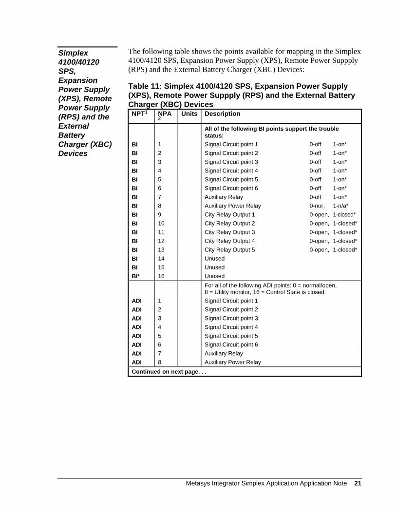
The following table shows the points available for mapping in the Simplex 4100/4120 SPS, Expansion Power Supply (XPS), Remote Power Suppply (RPS) and the External Battery Charger (XBC) Devices:
Simplex 4100/40120 SPS, Expansion Power Supply (XPS), Remote Power Supply (RPS) and the External Battery Charger (XBC) Devices
Table 11: Simplex 4100/4120 SPS, Expansion Power Supply (XPS), Remote Power Suppply (RPS) and the External Battery Charger (XBC) Devices NPT1 NPA
2 Units Description
All of the following BI points support the trouble status:
BI 1 Signal Circuit point 1 0-off 1-on* BI 2 Signal Circuit point 2 0-off 1-on* BI 3 Signal Circuit point 3 0-off 1-on* BI 4 Signal Circuit point 4 0-off 1-on* BI 5 Signal Circuit point 5 0-off 1-on* BI 6 Signal Circuit point 6 0-off 1-on* BI 7 Auxiliary Relay 0-off 1-on* BI 8 Auxiliary Power Relay 0-nor, 1-n/a* BI 9 City Relay Output 1 0-open, 1-closed* BI 10 City Relay Output 2 0-open, 1-closed* BI 11 City Relay Output 3 0-open, 1-closed* BI 12 City Relay Output 4 0-open, 1-closed* BI 13 City Relay Output 5 0-open, 1-closed* BI 14 Unused BI 15 Unused BI* 16 Unused For all of the following ADI points: 0 = normal/open,
8 = Utility monitor, 16 = Control State is closed ADI 1 Signal Circuit point 1 ADI 2 Signal Circuit point 2 ADI 3 Signal Circuit point 3 ADI 4 Signal Circuit point 4 ADI 5 Signal Circuit point 5 ADI 6 Signal Circuit point 6 ADI 7 Auxiliary Relay ADI 8 Auxiliary Power Relay Continued on next page. . .
Metasys Integrator Simplex Application Application Note 21
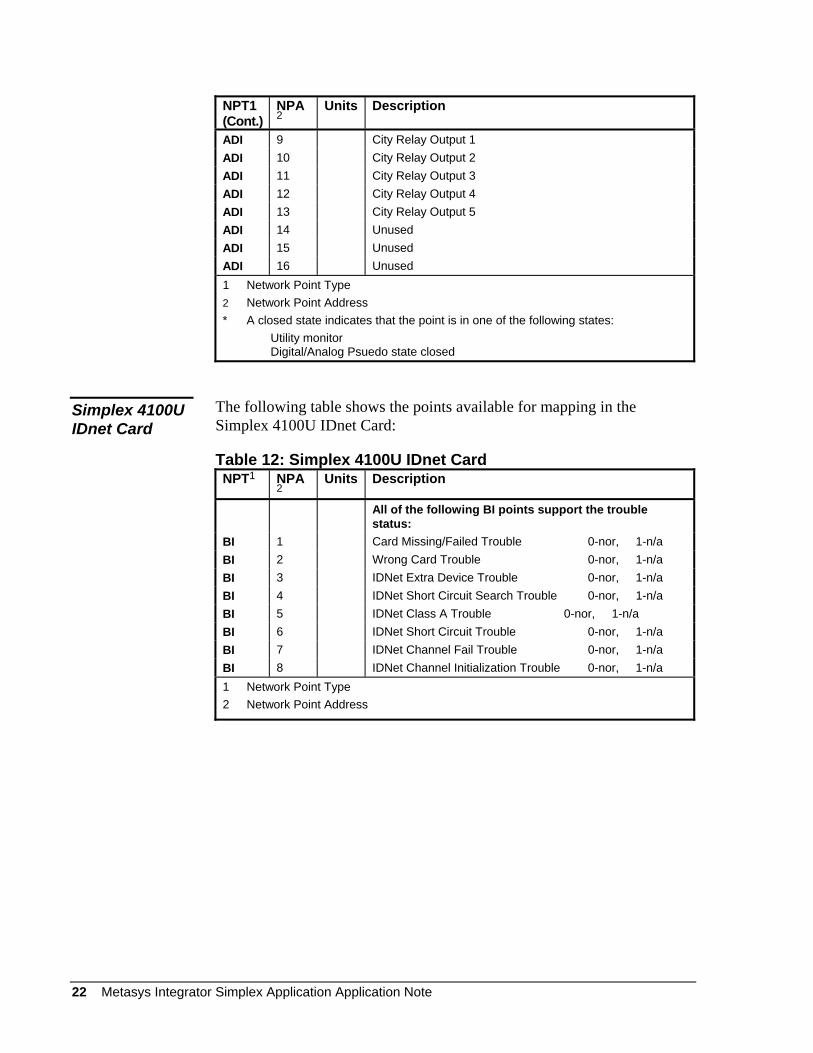
NPT1 (Cont.)
NPA2
Units Description
ADI 9 City Relay Output 1 ADI 10 City Relay Output 2 ADI 11 City Relay Output 3 ADI 12 City Relay Output 4 ADI 13 City Relay Output 5 ADI 14 Unused ADI 15 Unused ADI 16 Unused 1 Network Point Type 2 Network Point Address * A closed state indicates that the point is in one of the following states: Utility monitor
Digital/Analog Psuedo state closed
The following table shows the points available for mapping in the Simplex 4100U IDnet Card:
Simplex 4100U IDnet Card
Table 12: Simplex 4100U IDnet Card NPT1 NPA
2 Units Description
All of the following BI points support the trouble status:
BI 1 Card Missing/Failed Trouble 0-nor, 1-n/a BI 2 Wrong Card Trouble 0-nor, 1-n/a BI 3 IDNet Extra Device Trouble 0-nor, 1-n/a BI 4 IDNet Short Circuit Search Trouble 0-nor, 1-n/a BI 5 IDNet Class A Trouble 0-nor, 1-n/a BI 6 IDNet Short Circuit Trouble 0-nor, 1-n/a BI 7 IDNet Channel Fail Trouble 0-nor, 1-n/a BI 8 IDNet Channel Initialization Trouble 0-nor, 1-n/a 1 Network Point Type 2 Network Point Address
22 Metasys Integrator Simplex Application Application Note
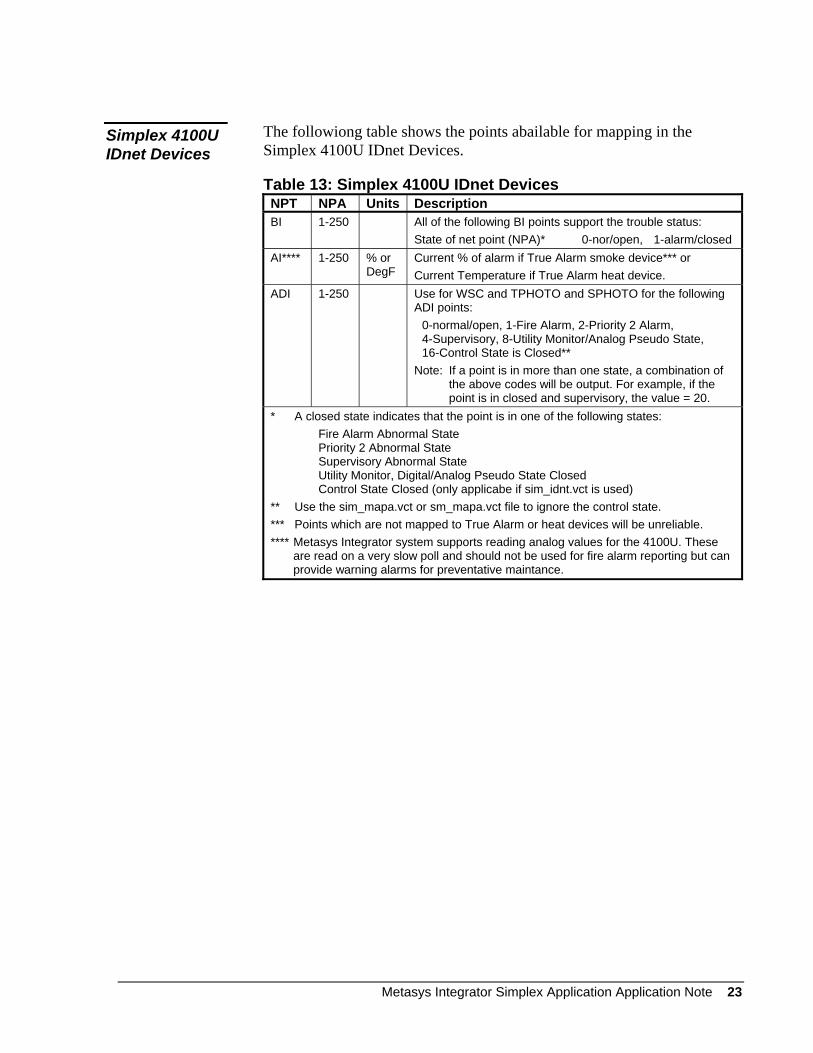
The followiong table shows the points abailable for mapping in the Simplex 4100U IDnet Devices.
Simplex 4100U IDnet Devices
Table 13: Simplex 4100U IDnet Devices NPT NPA Units Description BI 1-250 All of the following BI points support the trouble status:
State of net point (NPA)* 0-nor/open, 1-alarm/closed AI**** 1-250 % or
DegF Current % of alarm if True Alarm smoke device*** or Current Temperature if True Alarm heat device.
ADI 1-250 Use for WSC and TPHOTO and SPHOTO for the following ADI points: 0-normal/open, 1-Fire Alarm, 2-Priority 2 Alarm, 4-Supervisory, 8-Utility Monitor/Analog Pseudo State, 16-Control State is Closed** Note: If a point is in more than one state, a combination of
the above codes will be output. For example, if the point is in closed and supervisory, the value = 20.
* A closed state indicates that the point is in one of the following states: Fire Alarm Abnormal State
Priority 2 Abnormal State Supervisory Abnormal State Utility Monitor, Digital/Analog Pseudo State Closed Control State Closed (only applicabe if sim_idnt.vct is used)
** Use the sim_mapa.vct or sm_mapa.vct file to ignore the control state. *** Points which are not mapped to True Alarm or heat devices will be unreliable. **** Metasys Integrator system supports reading analog values for the 4100U. These
are read on a very slow poll and should not be used for fire alarm reporting but can provide warning alarms for preventative maintance.
Metasys Integrator Simplex Application Application Note 23
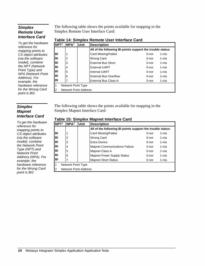
The following table shows the points available for mapping in the Simplex Remote User Interface Card:
Simplex Remote User Interface Card To get the hardware reference for mapping points to CS object attributes (via the software model), combine the NPT (Network Point Type) and NPA (Network Point Address). For example, the hardware reference for the Wrong Card point is BI2.
Table 14: Simplex Remote User Interface Card NPT1 NPA2 Unit Description All of the following BI points support the trouble status: BI BI BI BI BI BI BI
1 2 3 4 5 6 7
Card Missing/Failed 0-nor 1-n/a Wrong Card 0-nor 1-n/a External Bus Short 0-nor 1-n/a External UART 0-nor 1-n/a Internal UART 0-nor 1-n/a External Bus Overflow 0-nor 1-n/a External Bus Class-A 0-nor 1-n/a
1 Network Point Type 2 Network Point Address
The following table shows the points available for mapping in the Simplex Mapnet Interface Card:
Simplex Mapnet Interface Card To get the hardware reference for mapping points to CS object attributes (via the software model), combine the Network Point Type (NPT) and Network Point Address (NPA). For example, the hardware reference for the Wrong Card point is BI2.
Table 15: Simplex Mapnet Interface Card NPT1 NPA2 Unit Description All of the following BI points support the trouble status: BI BI BI BI BI BI BI
1 2 3 4 5 6 7
Card Missing/Failed 0-nor 1-n/a Wrong Card 0-nor 1-n/a Extra Device 0-nor 1-n/a Mapnet Communications Failure 0-nor 1-n/a Mapnet Class A 0-nor 1-n/a Mapnet Power Supply Status 0-nor 1-n/a Mapnet Short Status 0-nor 1-n/a
1 Network Point Type 2 Network Point Address
24 Metasys Integrator Simplex Application Application Note
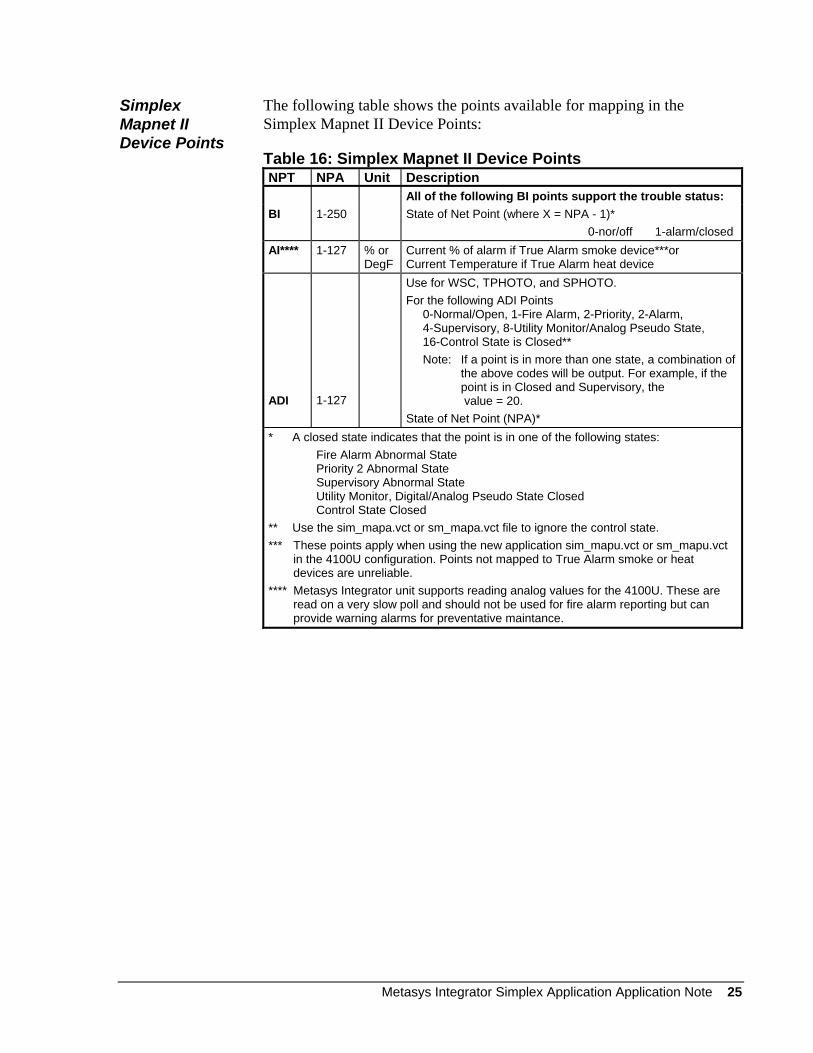
Simplex Mapnet II Device Points
The following table shows the points available for mapping in the Simplex Mapnet II Device Points:
Table 16: Simplex Mapnet II Device Points NPT NPA Unit Description All of the following BI points support the trouble status: BI 1-250 State of Net Point (where X = NPA - 1)*
0-nor/off 1-alarm/closed AI**** 1-127 % or
DegF Current % of alarm if True Alarm smoke device***or Current Temperature if True Alarm heat device
ADI
1-127
Use for WSC, TPHOTO, and SPHOTO. For the following ADI Points 0-Normal/Open, 1-Fire Alarm, 2-Priority, 2-Alarm, 4-Supervisory, 8-Utility Monitor/Analog Pseudo State, 16-Control State is Closed** Note: If a point is in more than one state, a combination of
the above codes will be output. For example, if the point is in Closed and Supervisory, the value = 20.
State of Net Point (NPA)* * A closed state indicates that the point is in one of the following states: Fire Alarm Abnormal State Priority 2 Abnormal State Supervisory Abnormal State Utility Monitor, Digital/Analog Pseudo State Closed Control State Closed ** Use the sim_mapa.vct or sm_mapa.vct file to ignore the control state. *** These points apply when using the new application sim_mapu.vct or sm_mapu.vct
in the 4100U configuration. Points not mapped to True Alarm smoke or heat devices are unreliable.
**** Metasys Integrator unit supports reading analog values for the 4100U. These are read on a very slow poll and should not be used for fire alarm reporting but can provide warning alarms for preventative maintance.
Metasys Integrator Simplex Application Application Note 25
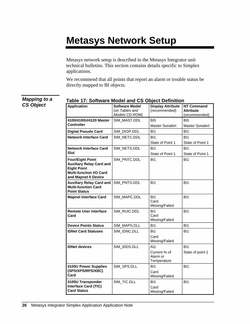
Metasys Network Setup
Metasys network setup is described in the Metasys Integrator unit technical bulletins. This section contains details specific to Simplex applications.
We recommend that all points that report an alarm or trouble status be directly mapped to BI objects.
Mapping to a CS Object
Table 17: Software Model and CS Object Definition Application Software Model
(on Tables and Models CD-ROM)
Display Attribute (recommended)
NT Command Attribute (recommended)
4100/4100U/4120 Master Controller
SIM_MAST.DDL
BI5 Master Sonalert
BI5 Master Sonalert
Digital Pseudo Card SIM_DIGP.DDL BI1 BI1 Network Interface Card SIM_NETC.DDL BI1
State of Point 1 BI1 State of Point 1
Network Interface Card Slot
SIM_NETS.DDL BI1 State of Point 1
BI1 State of Point 1
Four/Eight Point Auxiliary Relay Card and Eight Point Multi-function I/O Card and Mapnet II Device
SIM_PNTC.DDL BI1 BI1
Auxiliary Relay Card and Multi-function Card Point Status
SIM_PNTS.DDL BI1 BI1
Mapnet Interface Card SIM_MAPC.DDL BI1 Card Missing/Failed
BI1
Remote User Interface Card
SIM_RUIC.DDL BI1 Card Missing/Failed
BI1
Device Points Status SIM_MAPS.DLL BI1 BI1 IDNet Card Statuses SIM_IDNC.DLL BI1
Card Missing/Failed
BI1
IDNet devices SIM_IDDS.DLL AI1 Current % of Alarm or Temperature
BI1 State of point 1
4100U Power Supplies (SPS/XPS/RPS/XBC) Card
SIM_SPS.DLL BI1 Card Missing/Failed
BI1
4100U Transponder Interface Card (TIC) Card Status
SIM_TIC.DLL BI1 Card Missing/Failed
BI1
26 Metasys Integrator Simplex Application Application Note
Custom Integration
For information on integrating products that are not discussed in this document, first refer to the Metasys Compatible Products online list of released connectivity products. If this list does not provide the information you require, consider using the Systems Integration Services (SIS) Request Custom Engineered Solutions process to request a custom contract from the System Integration Team.
Access both the Metasys Compatible Products and the Request Custom Engineered Solutions process from The Advisor by performing the following steps:
1. Click on the Products Focus link, located at the top of The Advisor home page.
2. Under Products, click on the Systems Integration Services link.
3. For the searchable database, click on Metasys Compatible Products.
4. Select Metasys Compatible Products Database.
5. Click Online Search Tool.
6. After the search is completed, return to the Systems Integration Services home page as instructed in Steps 1-2.
7. Select Custom Engineered Solutions to view the process used for requesting all types of SIS engineered solutions and services.
8. Select Requesting an Engineered Solution or Service.
9. Click Online Request Page.
If you need further assistance, contact the Johnson Controls® Field Support Center.
Controls Group 507 E. Michigan Street P.O. Box 423 www.johnsoncontrols.com Milwaukee, WI 53201 Published in U.S.A.
Metasys Integrator Simplex Application Application Note 27