metfloor shallow composite floor decks
TRANSCRIPT

32 33
Shallow Composite Floor DecksDesign information
Composite floor decking design is generallydictated by the construction stage condition,the load and span required for service, and thefire resistance required for the slab. Deck designis also influenced by the composite beamdesign.
Design Parameters
• Fire rating – dictates minimum slab depth.• Concrete type – also dictates minimum slab depth and
influences unpropped deck span.• Deck span – (unpropped) usually dictates general beam
spacing.• Slab span – (propped deck) dictates maximum beam spacing.
Two Stage Design
All Composite Floors must be considered in two stages.• Wet Concrete and construction load
– carried by deck alone.• Cured concrete
– carried by composite slab.
General design aimsDesigners generally aim to reduce temporary propping, so thespan and slab depth required governs the deck selection. Firerequirements usually dictate slab depth. For most applications,the imposed load on the slab will not limit the design.
Anti-crack meshFibreDeck can be used to replace anti crack mesh. Where meshis used, BS 5950: Part 4 recommends that it comprises 0.1% ofslab area. Eurocode 4 recommends that anti-crack mesh shouldbe made up from 0.2% of slab area for unpropped spans and0.4% of slab area for propped spans. The mesh shown in thequick reference tables complies with EC4 and the designprogram defaults to these values. You can still use the reducedBS mesh values by overriding this default in the design program.In slabs subject to line loads, the mesh should comprise 0.4% ofthe cross-sectional area of the concrete topping, propped andunpropped. These limits ensure adequate crack control invisually exposed applications (0.5 mm maximum crack width).The mesh reinforcement should be positioned at a maximum of30 mm from the top surface. Elsewhere, 0.1% reinforcementmay be used to distribute local loads on the slab (or 0.2% toEC4). Mesh laps are to be 300mm for A142 mesh and 400mmfor A193, A252 & A393.
Using forklift trucksIf you expect to use a forklift truck - or a similar concentratedloading - then you should use 0.5% minimum percentagereinforcement over the supports and 0.2% elsewhere to controlcracking. See SCI AD150 for further information.
Working on exposed floorsComposite floors are usually covered by finishes, flooring or acomputer floor, and because cracking is not visible, light topreinforcement is adequate - typically 0.1% of the gross crosssectional area. However where the composite slab is leftuncovered - such as for power- trowelled floor finishes -
cracking, particularly over the beams, may not be adequatelycontrolled by the light mesh provided. Although the crackingdoes not have any structural significance, you might see itsappearance - and the possibility of the crack edge breakdownunder traffic - as problems. To address this, refer to ConcreteSociety publication, 'Cracking In Composite Concrete/CorrugatedMetal Decking Floors Slabs' which provides valid mesh sizing anddetailing for specific crack width control.
If you are going to use forklifts you should also refer to SteelConstruction Institute advisory note 'AD 150, Composite Floors- Wheel Loads From Forklifts'.
Reduced mesh
If you are going to use EC4 mesh rules - as recommended bySteel Construction Institute and CMF - the full stipulated meshapplies to the slab 1.2m either side of every support. Elsewhere– such as in the midspan area – you may half the mesh area (to0.2% for propped and 0.1% for unpropped construction), aslong as there are no concentrated loads, openings or similar tobe considered. You must also check the reduced midspan meshfor adequacy under fire, for the rating required.
Bar reinforcementThe axis distance of bar reinforcement defines the distance fromthe bottom of the ribs to the centre of the bar, which has aminimum value of 25 mm, and a maximum value of the profileheight. Where used, bar reinforcement is placed at one bar perprofile trough.
Transverse reinforcementMetFloor® composite floor decks contribute to transversereinforcement of the composite beam, as long as the decking iseither continuous across the top flange of the steel beam or –alternatively - it is welded to the steel beam by stud shearconnectors. To find out more refer to BS5950:Part 3: Section3.1.Clause 5.6.4.
Choosing the concreteLightweight concrete (LWC) uses artificially produced aggregatesuch as expanded pulverised fuel ash pellets. This gives LWCconsiderable advantages in improved fire performance, reducedslab depth, longer unpropped spans and reduced dead load.
However, at the present time, LWC is not readily available insome parts of the country. Normal weight concrete uses anatural aggregate and is widely available. The strength of theconcrete must meet the requirements for strength of thecomposite slab and should not be less than 25N/mm2 for LWCor 30N/mm2 for NWC. Similarly, the maximum value of concretestrength should not be taken as greater than 40 for LWC or 50for NWC.
The modular ratio defines the ratio of the elastic modulus of
steel to concrete, as modified for creep in the concrete. In design to BS5950 and BS8110, the cube strength is used (in N/mm2). In design to EC3, the cylinder strength is used (in N/mm2). The concrete grade (C30/37) defines the (cylinder/cube strength) to EC3.
Concrete density
Without the precise information you should assume that wetdensity is used in the design of the profiled steel sheets and thatdry density in the design of the composite slab.
Fire Design
Fire insulationYou must take the fire insulation requirements of BS 5950: Part8 into account in the tables and design software.
Span/depth ratioSlab span to depth ratio is limited to a maximum of 30 forlightweight concrete and 35 for normal weight concrete.
Shear connectors in fire situationIf shear connectors are provided you can ignore any catenaryforces transferred from the slab to the support beams within thefire resistance periods quoted.
Fire Design Methods
There are two requirements here:• Bending resistance in fire conditions• Minimum slab depth for insulation purposes
You can calculate the capacity of the composite slab in fireusing the simple method or the fire engineering method:
Simple methodThe simple method is most economic and can be used forsimply supported decks or for decks continuous over one ormore internal supports. The capacity assessment in fire isbased on a single or double layer of standard mesh. Any barreinforcement is ignored.Fire engineering methodThe fire engineering method is for general application andshould be used for design to Eurocodes. The capacityassessment in fire is based on a single or double layer ofstandard mesh at the top and one bar in each concrete rib.For the shallow decks, the program assumes the bar ispositioned just below the top of the steel deck. For MetFloor®
60 with a raised dovetail in the crest the bar will be placedbelow the dovetail.
The quick reference tables for shallow composite floorsgenerally use the simplified fire design method, which utilisesthe anticrack mesh as fire reinforcement. You can increase loadspan capability under fire by including bar reinforcement andusing the fire engineering design method.
Deflection limitsYou would normally agree deflection limits with the client. Inthe absence of precise information adopt the following limits:
• Construction stageLe/130 (but not greater than 30mm)
• Imposed load deflectionLe/350 (but not greater than 20mm)
• Total load deflectionLe/250 (but not greater than 30mm)
According to BS5950 Part 4, ponding, resulting from thedeflection of the decking is only taken into account if theconstruction stage deflection exceeds Ds/10. Le is the effectivespan of the deck and Ds is the slab overall depth (excludingnon-structural screeds).
When the ponding of the concrete slab is not taken intoaccount, the deflection under construction load should notexceed the span/180 or 20mm overall – whichever is the lesser.
Where ponding is taken into account the deflection should notexceed the span/130 or 30mm overall. The quick referencetables do take ponding into account, if deflection exceedsDs/10, or Le/180, and thus use span/130 or 30mm as adeflection limit. We recommend that the prop width should notbe less than 100mm otherwise the deck may mark slightly atprop lines.
VibrationCheck the dynamic sensitivity of the composite slab by referringto the Steel Construction Institute publication P076: Designguide on the vibration of floors. Calculate the natural frequencyusing the self-weight of the slab, ceiling and services, screedand 10% imposed loads, representing the permanent loads andthe floor.
Where there is no specific information you should ensure thatthe natural frequency of the composite slab is not greater than5Hz for normal office, industrial or domestic usage. Forapplications such as dance floors or those which supportsensitive machinery you may need to set the limit higher.
For design to the Eurocodes, the loads considered for thevibration check are increased using the psi-factor for imposedloads (typically 0.5). You can reduce the natural frequency limitto 4Hz, because of the higher load used in the calculation. Todetermine the vibration response of sensitive floors with greateraccuracy look at the calculation methods in the SCI / CMFpublication P354 “Design of Floors for Vibration: A NewApproach”. These figures enable designers to compare theresponse with the acceptance levels in BS 6472 and ISO 10137for building designs and in the NHS performance standard forhospitals, HTM 2045.
Shallow Composite Floor DecksDesign information
1.2m 1.2m
SupportBeam
SupportBeam
SupportBeam
1.2m 1.2m
Diagram showing full mesh area over supports
Density kg/m3
Wet Dry Modular Ratio
LWC 1900 1800 15
NWC 2400 2350 10
Metfloor®

Section B-B
Section A-A
34 35
Loads and load arrangementOrdinarily you would agree loading information directly withyour clients. You should also refer to BS 6399 and to EC1.Factored loads are considered at the ultimate limit state andunfactored loads at the serviceability limit state. Unfactoredloads are also considered in fire conditions. Partial factors aretaken from BS5950, EC3 and EC4.
Loads considered at the construction stage consist of the slabself weight and the basic construction load. The basicconstruction load is taken as 1.5 kN/m2 or 4.5/Lp (whichever isgreater), where Lp is the span of the profiled steel sheetsbetween effective supports in metres. For multi-span unproppedconstruction the basic construction load of 1.5 kN/m2 isconsidered over the one span only. On other spans, theconstruction load considered is half this value (i.e. 0.75 kN/m2).Construction loads are considered as imposed loads for thischeck.
Loads considered at the normal service stage consist of the slabself weight, superimposed dead loads and imposed loads.
Openings
You can accommodate openings easily in composite slabs byboxing out before pouring the concrete and cutting out thedeck after the concrete has cured (see the ‘Sitework’ section onpage 39).
The design of openings depends on their size:
• SmallFor openings up to 300 mm square there is normally no needfor any additional reinforcement.
• MediumOpenings between 300 mm and 700 mm square normallyrequire additional reinforcement to be placed in the slab. Thisis also true if the openings are placed close together.
• LargeYou should trim openings greater than 700mm square withadditional permanent steelwork back to the support beams.
Opening rulesWhere W = width of opening across the span of the deck.
1. The distance between the opening and unsupported edgemust be greater than 500mm or W, whichever is the greater.
2. Openings must not be closer together than 1.5W (of thelargest opening) or 300mm, whichever is the greater. If theyare closer they must be considered as one opening.
3. Not more than 1/4 width of any bay is to be removed byopenings.
4. Not more than 1/4 width of deck span is to be removed byopenings.
Where these rules are not met the openings must be fullytrimmed with support steelwork.
If the opening falls within the usual effective breadth ofconcrete flange of any composite beams (typically span/8 eachside of the beam centre line), check the beam resistanceassuming an appropriately reduced effective breadth of slab.
Slab design around openingsYou should assume that an effective system of ‘beam strips’span the perimeter of the opening. Take the effective breadth ofthe beam strips to be do/2 where do is the width of theopening in the direction transverse to the decking ribs. Only theconcrete above the ribs is effective.
The transverse beam strips are assumed to be simply supportedand span a distance of 1.5 do. The longitudinal beam strips are
designed to resist the load from the transverse beam strips inaddition to their own proportion of the loading.
ReinforcementExtra reinforcement is provided within the ‘beam strips’ to suitthe applied loading. This reinforcement often takes the form ofbars placed in the troughs of the decking. You can useadditional transverse or diagonal bars to improve load transferaround the opening.
Shallow Composite Floor DecksDesign information
Shallow Composite Floor DecksDesign information
Centre Lineof Floor Beam
Centre Lineof Floor Beam
Deck Span
Transverse reinforced concrete beam strip
Longitudinal reinforcedconcrete beam strips
Effective span of transverse beam strips = 1.5d o
do /2
do /2
do
do /2 do /2Extra bars in slab (over the deck)
Extra bars in trough
Opening
B
B
A
A
Mesh
Extra bars in trough
Extra bars in over deck
Metfloor®

3736
Shear stud designYou can make up to 50% savings in beam weight if compositeslab is effectively anchored to the steel beam. The slab will thenact as a compression flange to the beam.
The slab and beam are generally connected by through-deckwelding of 19mm diameter shear studs of varying height whichare fixed to the beam after the decking has been laid.
Shear stud specification• 19mm x 95mm studs are used with MetFloor® 55 and
MetFloor® 60
• 19mm x 125mm studs are used with MetFloor® 80
Shallow Composite Floor DecksDesign information
Headed studsWhen deck profile ribs are running perpendicular to the steelbeam – that is compositely connected to the composite slab –you should take the capacity of headed studs as capacity in asolid slab but multiplied by the reduction factor “k”. Thecalculation method for “k” differs between BS5950 Part 3 andEurocode 4.
Deck suitabilityYou cannot place shear studs on profile stiffeners. However,with MetFloor® 60 and MetFloor® 80 the position of thestiffeners and side lap lets you place the studs centrally.
Non-welded shear connectorsYou can use Hilti shear connectors. For further information referto Hilti.
Design notesFor further reference please see The Steel ConstructionInstitute/Metal Cladding and Roofing Manufacturers AssociationP300 “Composite Slabs and Beams using Steel Decking: BestPractice for Design and Construction”.
Shallow Composite Floor DecksDesign information
Force applied to shear stud
Crushing
Top flange of beam Force applied to slab
Crushing
Central Studs*76mm = 4d for 19mm studs
25mm min, edge of stud to edge of beam
76*mm min.
Metfloor®
3938
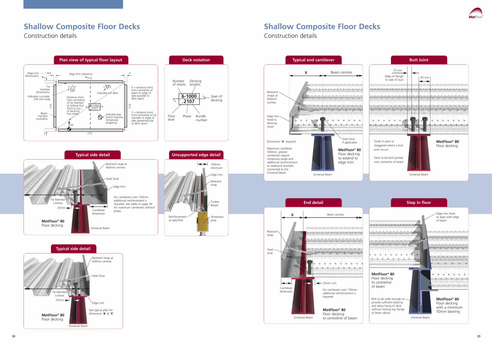
Shallow Composite Floor Decks Construction details
Shallow Composite Floor Decks Construction details
Edge trim reference
Indicates cut plate245 mm wide
Indicates cut deck
Edge trimdimensions
F75
F75
Distance (mm)from centreline of tie member to Setting OutPoint (s.o.p.)of deckingfirst sheet.
X = distance (mm) from centreline ofbeam to edge of slab (parallel to deck span)
Y = distance (mm)from centreline of tie member to edge of slab (perpendicular to deck span)
Indicates baywhich requirestemporarypropping.
94
245C P
F75
F75
X X
Beammember
centreline
Tiemember
dimensions
Y
Y
C D
6-10002107
Plan view of typical floor layout Deck notation
Typical side detail
MetFloor® 80Floor decking
X
Edge trim
See typical plan fordimension ‘X’ & ‘Y’
Universal Beam
Tie MemberCentres
25mm
Restraint strap at600mm centres
Steel Stud
Typical side detail
MetFloor® 80Floor decking
Y
Edge trim
Universal Beam
CantileverDimension
Tie MemberCentres
25mm
Restraint strap at600mm centres
For cantilevers over 150mm,additional reinforcement isrequired. See table on page 39for maximum cantilevers withoutprops.
Steel Stud
Number of sheets
Bundle number
PhaseFloor level
Span of decking
6-10002107
Decking lengths
Unsupported edge detail
100mmminimum
Edge trim
Restraintstrap
TimberBearer
Temporaryprop
Reinforcementas specified
Typical end cantilever Butt Joint
Edge trimfixed todeckingsheet
Universal Beam Universal Beam
Steel Stud if applicable
End detail Step in floor
X Beam centres
Restraintstraps at600mmcentres
Restraintstrap
Steel stud
MetFloor® 80 Floor decking to extend toedge trim
Dimension ‘X’ required
Maximum cantilever500mm, greatercantilevers requiretemporary props andadditional reinforcementor steelwork bracketsconnected to theUniversal Beam
MetFloor® 80 Floor decking
MetFloor® 80 Floor deckingwith a minimum50mm bearing
Edge trim fixed to align with edge of beam
Studs in pairs orstaggered where a buttjoint occurs
Deck to be butt jointedover centreline of beam
50 minEdge of flange to side of stud
25 min
X Beam centres
Cantileverdimension
25mm min
For cantilevers over 150mmadditional reinforcement isrequired.
RSA to be wide enough toprovide sufficient bearingand allow fixing of deckwithout fouling top flangeof beam above
MetFloor® 80 Floor deckingto centrelineof beam
MetFloor® 80 Floor deckingto centreline of beamUniversal Beam Universal Beam
Metfloor®
4140
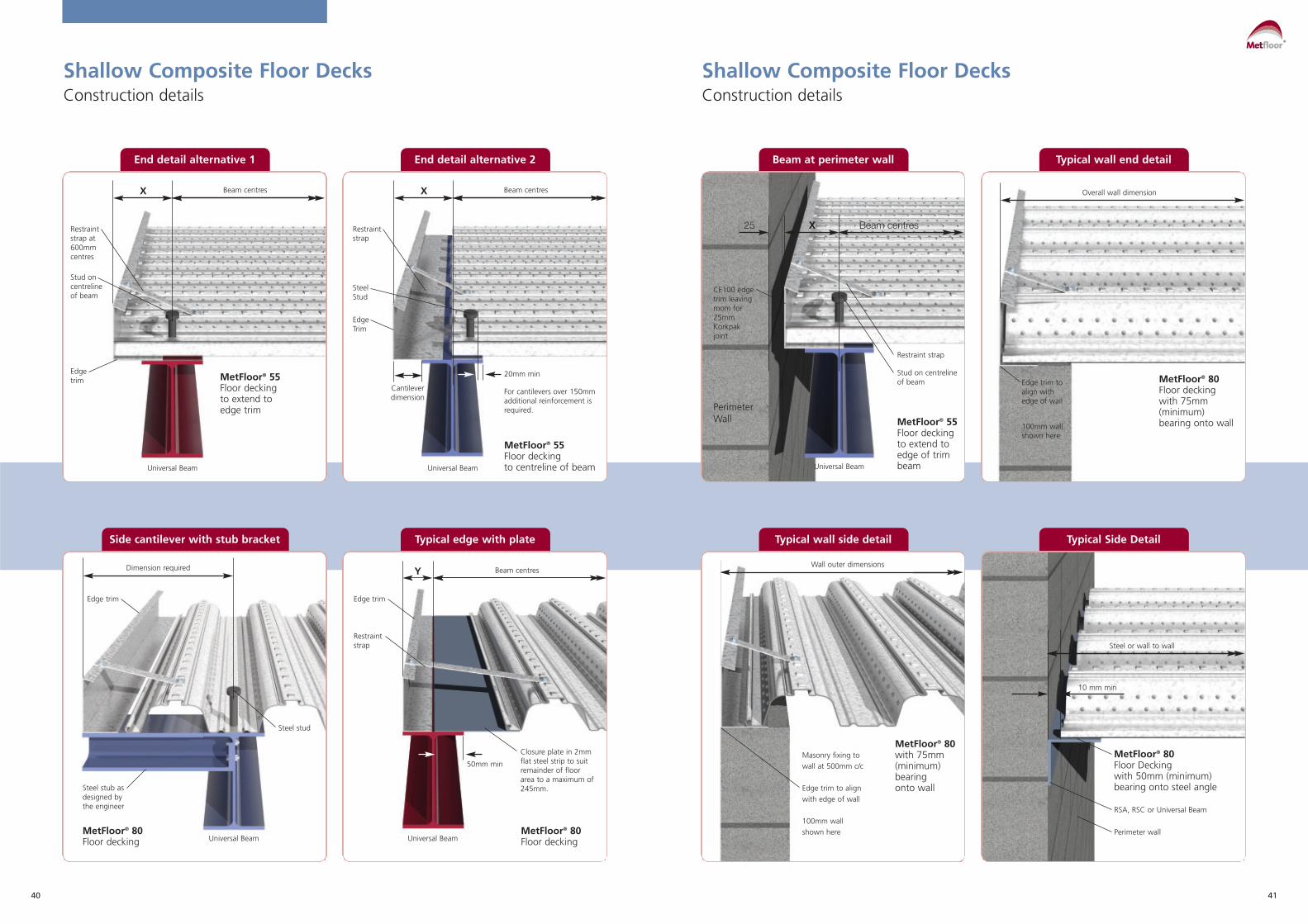
End detail alternative 1 End detail alternative 2
MetFloor® 55Floor decking to extend to edge trim
Universal Beam Universal Beam
Side cantilever with stub bracket Typical edge with plate
Beam at perimeter wall
Universal Beam
PerimeterWall
CE100 edgetrim leavingroom for25mmKorkpakjoint
Typical wall end detail
Typical wall side detail Typical Side Detail
Shallow Composite Floor Decks Construction details
Shallow Composite Floor Decks Construction details
X Beam centres X Beam centres
Restraintstrap at600mmcentres
Stud oncentreline of beam
Restraintstrap
Restraint strap
Stud on centreline of beam
Steel Stud
Edge Trim
Edgetrim
Cantileverdimension
20mm min
50mm min
For cantilevers over 150mmadditional reinforcement isrequired.
Closure plate in 2mmflat steel strip to suitremainder of floorarea to a maximum of245mm.
MetFloor® 55 Floor deckingto centreline of beam
MetFloor® 55 Floor deckingto extend toedge of trimbeam
MetFloor® 80 with 75mm(minimum)bearing onto wall
MetFloor® 80 Floor Decking with 50mm (minimum)bearing onto steel angle
Masonry fixing to wall at 500mm c/c
Edge trim to align with edge of wall
100mm wallshown here
RSA, RSC or Universal Beam
Perimeter wall
MetFloor® 80 Floor deckingwith 75mm(minimum)bearing onto wall
MetFloor® 80 Floor deckingUniversal Beam Universal Beam
Steel stub asdesigned bythe engineer
Steel stud
Edge trim
Dimension required
MetFloor® 80Floor decking
Y Beam centres
Edge trim
Restraintstrap
X25 Beam centres
Edge trim toalign withedge of wall
100mm wallshown here
Overall wall dimension
Wall outer dimensions
Steel or wall to wall
10 mm min
Metfloor®

4342
Shallow Composite Floor Decks Sitework
Shallow Composite Floor Decks Sitework
Deck fixingAs soon as you lay the deck fix it throughits trough to the top of the supportingstructure using powder actuated pins orself-drilling screws. Use side lap fixings at1000mm centres for MetFloor® 60 andMetFloor® 80. Where shear studs arebeing used the deck needs two fixingsper sheet per support at sheet ends andone fixing per sheet at intermediatesupports.
Bearing requirements
Edge trimYou should use edge trim to maintain thewet concrete at the correct level at thedecking perimeters. Fix it to the supportsin the same manner as the deck andrestrain the top by straps at 600mmcentres fixed to the top of the deck profilewith steel pop rivets or self-drilling screws.
Fixing Information for Shallow Decking
To Steel Heavy duty powder actuated fixings - Hilti ENP2 X-ENP-19 L15 nail/Spit SBR14 or equivalent. For temporary fixing (i.e. where weld through shear studs are to be used) - Hilti PINDAK16*
Self-drilling screws. To steel up to 11mm thick - SFS SD14 - 5.5 x 32 / EJOT HS 38 or equivalent. To steel up to 17mm thick SFS TDC-T-6.3 x 38 or equivalent
To Masonry Pre drill hole - use self tapping fixing suitable for masonry/ or Concrete concrete - SFS TB-T range/EJOT 4H32 or equivalent
To side laps Self drilling stitching screw typically SFS SL range / EJOT or closures etc. SF25 or equivalent
2 fixings per sheet
Deck fixing on MetFloor® 80
End bearing and shared bearing (minimum)
Steel section
50mm 50mm
Masonry
70mm 70mm
Masonry
100mm
Continuous bearing (minimum)
Steel section
75mm
Edge Trim Selector
Edge Maximum Cantilever (mm) trim Galv. Steel Edge Trim Thickness (mm) depth 0.9 1.2 1.6 2.0
130 100 125 160 195
150 50 115 150 185
200 x 100 130 160
250 x 50 100 135
300 x x 50 100
350 x x x 50
x - not recommended
Metfloor®

4544
Shear connectorsThe most commonly used shear connectors are 19mm diameterheaded studs which are welded to the support beam throughthe deck by specialist stud welding contractors.
Make sure the site conditions are suitable for welding then carryout bend tests as necessary. The spacing and position of theshear connectors is important and must be defined by thedesign engineer on the deck set-out drawings.
Minimum Spacing: Ensure that the minimum centre-to spacingof stud shear connectors are 5d along the beam and 4dbetween adjacent studs, where d is the nominal shank diameter.Where rows of studs are staggered the minimum transversespacing of longitudinal lines of studs should be 3d. The shearstud should not be closer than 25mm to the edge of the beam.See page 37.
More informationTo find out more about shear studs in The Steel ConstructionInstitution publications: P300 Composite Slabs and Beams UsingSteel Decking: Best Practice for Design and Construction, P055Design of Composite Slabs and Beams with Steel Decking.
Placing the meshYou can utilise FibreFlor in place of anti-crack mesh, whicheliminates all mesh position issues. If you use reinforcing meshensure that you position it towards the top of the slab.
The top cover to the reinforcement mesh must be \a minimumof 15mm and a maximum of 30mm. Support stools are requiredto maintain the correct mesh height.
The mesh must be lapped by 300mm for A142 and A193 mesh,and by 400mm for A252 and A393 mesh.
Casting concreteAs dirt and grease could adversely influence the performance ofthe hardened slab, you should clear the decking before youpour the concrete (the oil left on the decking from the rollforming process may stay). Pour the concrete evenly, working inthe direction of span. Take care to avoid heaping concrete inany area during the casting sequence. Construction and dayjoints should occur over a support beam, preferably also at adeck joint.
Ceilings and services hanger systemsThe dovetail shaped re-entrant rib on MetFloor® 55 and theraised mini-dovetail re-entrant stiffener on MetFloor® 60 andMetFloor® 80 profiles let you suspend the ceiling and servicesquickly and easily.
There are two suspension systems:
(a) Threaded wedge nut fixings
Wedges are dovetail shaped steel blocks threaded to take metricbolts or threaded rods. The wedge nut hanger system isinstalled after the concrete of the composite slab has beenpoured and is hardened.
How to install the systemTo install the system insert the wedge nuts into the raised re-entrants of the profile before being rotating 90 degrees, afterwhich the dovetail shaped wedge nuts will lock into the dovetailre-entrants under vertical loading. Finger-tighten the bolts orthreaded rods up to the roof of the re-entrants and thenmechanically tighten.
(b) GTD-clip hangar fixings
GTD-clip hangar fixings are cold formed thin steel hangers withcircular openings in the soffit to take metric bolts, threaded rodsor further pipe clamp hangers. Install the system after pouringthe composite slab and the concrete is sufficiently hardened.
How to install the GTD-clipsTo install the GTD-clips compress the two dovetail shaped endsby hand and insert into the dovetail re-entrant of the profilebefore rotating by 90 degrees. After releasing the two ends theclip will snap into position – make sure it is tightly connected.Finally connect the bolts, threaded rods or pipe clamps into thesoffit opening of the GTD-clip.
Sitework Openings for Shallow Composite Floor DecksWhere openings are greater than 300mm, the engineer mustdesign them and provide extra reinforcement around theopening. Openings can be accommodated up to 700mm incomposite slabs by boxing out before pouring concrete andcutting out the deck after the concrete has cured. Largeropenings require support trimming steel and these must beinstalled prior to the decking. Cut the decking awayimmediately and treat the opening edges like any otherperimeter with edge trim.
Do not cut the opening in the steel deck before concreting orbefore the concrete has cured.
Temporary supportsThe contractor or designated sub-contractor is responsible forthe safe design and installation of temporary props. Where thedesign calls for temporary supports, these must providecontinuous support to the profiled sheeting. Spreader beams(timbers) should be used and supported by temporary props atone metre centres.
• The timbers and props must be of adequate strength andconstruction
• The temporary supports are placed at midspan or at othersuitable centres if more supports per span are required.
• The spreader beams or timbers should provide a minimumbearing width of l00mm.The spreaders must not deflect more than 10mm and shouldbe placed narrow edge up, see diagram.
• The propping structure is not to be removed until the concretehas reached at least 70% of its characteristic strength. Thehorizontal bearer timbers must be at least 100mm wide andshould be propped at no more than 1m centres. Sometimesthe specification may call for 150mm wide bearers, as
determined by the structural engineer or concretingcontractor.
The props should be stable without relying on friction with thedeck for laterial stability. The end props in a row should be selfsupporting, and braced to the internal props.
Percussive drillingWe do not recommend percussive drilling into compositeconcrete slabs although small-scale rotary hammer drills are fine.
Shallow Composite Floor Decks Sitework
Shallow Composite Floor Decks Sitework
MetFloor® 55 MetFloor® 80 Timber Shutter Dense polystyrene block
Temporary PropsTimber Bearer Guide (shallow decks)
All to be min. 100mm wide Slab depth (mm) Bearer depth(mm)
up to120 150
130 - 160 200
170 - 200 250
Temporary support using an ’Acrow’ type prop
Metfloor®

4746
Transport and Handling MetFloor®
References - Health and Safety MetFloor®
The following instructions are designed to helpcomposite flooring contractors.
Receiving the deckingWhen you receive the composite floor decking it will be packedinto bundles of up to 24 sheets and the sheets secured withmetal banding. A single bundle may be up to 950mm wide(the overall width of a single sheet) by 750 mm deep, and mayweigh up to 2.5 tonnes, depending on sheet length (averageweight is about 1.5 tonnes). The loads will normally delivered byarticulated lorries approximately 16m long with a maximumgross weight of up to 40 tonnes and a turning circle ofapproximately 19m. The main contractor should ensure thatthere is suitable access and appropriate standing and off-loadingareas.
Each bundle has an identification tag. Decking contractoroperatives should check the information on each tag - or, if theyare not on site, the main contractor - as soon as they havearrived. In particular, the stated sheet thickness should bechecked against the requirement specified on the contractdrawings. Operatives should also make a visual inspection toensure there is no damage.
Lifting bundlesLift bundles directly from the lorry. You should never off-load bytipping, dragging, dropping or any other improvised means.
Take special care when lifting the decking bundles - werecommend using protected chain slings, as unprotected chainslings can damage the bundle during lifting. When syntheticslings are used there is also a risk of severing them on the edgesof the decking sheets.
If you use timber packers ensure that they are secured to thebundle before you lift them so that when the slings are releasedthey do not fall to the ground. You must never lift the bundlesusing the metal banding.
Positioning the deckingPrepare the support steelwork to receive the decking before youlife the bundles onto it. Make sure the top surface of theunderlying beams is reasonably clean. When through-deckwelding of shear studs is specified, you should ensure that thetops of the flanges are free of paint or galvanising.
Use the identification tags to ensure that the bundles arepositioned on the frame at the correct floor level and in thenominated bay shown on the deck layout drawing. Position thebundles so that the interlocking side laps are on the same side.This will enable you to lay the decking progressively withouthaving to turn the sheets. The bundles should also bepositioned in the correct span orientation, and not at 90º to it.Take care to ensure that the bundles are not upside down,particularly with trapezoidal profiles. The embossments shouldbe oriented so that they project upwards.
Placing the deckingBreak open bundles and install decking only if all the sheets canbe positioned and secured. You will need adequate time as wellas good weather. Check the decking layout drawing to makesure that any temporary supports that are needed are in placebefore. You will normally get access for installation by usingladders connected to the steel frame. Once they have startedlaying out the sheets, the erectors will build their own workingplatform by securely fixing the decking as they progress. Startlaying out the sheets at the locations indicated on the deckinglayout drawings. These are normally at the corner of thebuilding at each level; to reduce the number of ‘leading edges’(that is, the unprotected edges where the decking is being laid).
When you have properly positioned the bundles there should beno need to turn the sheets manually, and no doubt which wayup the sheet should be fixed. Slide the individual sheets and,where possible, fix to the steelwork before moving onto thenext sheet – this will minimise the risk of an accident as a resultof movement of a sheet when it is being used as a platform.(However, for setting-out purposes, it may be necessary to layout an entire bay using a minimum number of temporary’fixings before fully securing the sheets later). Position the sheetsto provide a minimum bearing of 50 mm on the steel supportbeams. Butt the ends of adjacent sheets together – a gap of upto 5 mm is normally considered effective in not allowingexcessive seepage but, if necessary, you can tape the ends ofthe sheets together. When end gaps are greater than 5 mm, it isnormally fine to seal them with an expanding foam filler. Thelongitudinal edges should be overlapped, to minimise concreteseepage.
Cutting sheetsWhere necessary, you can cut the sheets using a grinder or anibbler. However, you should keep field cutting to a minimum (itis only really necessary where a column or other obstructioninterrupts the decking). Ensure that gaps adjacent to the websof columns are filled in with off-cuts or thin strips of steel.
Decking sheets shown as continuous on the decking layoutdrawing should never be cut into more than one length. Also,sheets should never be severed at the location of a temporarysupport, and the decking should never be fastened to atemporary support.
As you progress, you should dispose of unwanted scraps andoff-cuts in a skip placed at the right level to where you areworking. Position the skip carefully over a support beam toavoid overloading the decking. If you do not have a skip, gatherthe scraps for collection by the main contractor as soon aspossible. Secure partially used bundles to avoid individual sheetsmoving in strong winds.
British Standards compliant
The following instructions are designed to helpcomposite flooring contractors.
Composite Floor Deck1. BS 5950: Part 4 1994. Structural use of steelwork in building:
Code of practice for design of composite slabs with profiledsteel sheeting.
Composite Steel Beams2. BS 5950: Part 3: 1990. Design in composite construction:
Section 3.1: 1990. Code of practice for design of simple andcontinuous composite beams.
Profiled Steel Deck3. BS 5950: Part 6 1995. Structural use of steelwork in building:
Code of practice for design of light gauge profiled steelsheeting.
Fire Resistance4. BS 5950: Part 8 2003. Structural use of steelwork in building:
Code of practice for fire resistant design.
Concrete5. BS 8110: Part 1: 1997 Structural use of concrete:
Code of practice for design and construction.6. BS 8110: Part 2: 1985 Structural use of concrete:
Code of practice for special circumstances.
Reinforcement7. BS 4483: 2005 Specification for steel fabric for the
reinforcement of concrete.8. BS 4449: 2005 Specification for carbon steel bars for the
reinforcement of concrete.9. BS 4482: 2005 Steel wire for the reinforcement of concrete
products specification.
Eurocode 3 and 410. EC3 ENV 1993 - 1 - 3: 2001 Design of steel structures.
Supplementary rules for cold formed thin gauge membersand sheeting.
11. EC4 ENV 1994 - 1 - 1: 1994 Design of Composite steel andconcrete structures. General rules for building.
12. EC4 ENV 1994 - 1 - 2: 2001 Design of composite steel andconcrete structures. Structural fire design.
13. SCI - P - 076 : Design guide on the vibration of floors. SCI inassociation with CIRIA (1989).
Health and Safety
Handling HazardsHandle Zinc coated steel decking with care as it may bedelivered with soluble protective layer of oil which can causecontamination to lacerated skin. You should also wear adequateprotective gloves and clothing when handling decking as it willhave sharp edges and corners.
Eye HazardsAlways wear eye protectors conforming to the specification inBS 2092:1987 when breaking the strapping around bundles asthe sudden release of tension creates can be very hazardous.You should also wear eye protection when cutting steel as flyingparticles of metal can also be very dangerous.
Noise HazardsMake sure you wear adequate ear defenders when handling orcutting decking and shot firing as the noise levels can behazardous.
Respiratory HazardsFumes containing oxides of iron and zinc are produced duringwelding or flame cutting and if inhaled these may cause metalfume fever; this is a short-lasting condition with symptomssimilar to those of influenza. In conditions of exposure to suchhazards, the use of respiratory equipment is recommended.
Explosives and FumesTake extra care when using shot fired fixings as explosives andfumes can create hazards.
Occupational Exposure LimitsLimits for iron and zinc oxides are 5g/m_> (8 hours TWA) and10mg/m_< (10 minutes TWA). (OE recommendation)
Summary of Protective MeasuresMake sure that you wear adequate protective gloves andclothing and safety goggles. Ensure adequate ventilation anduse personal protective equipment. Follow the instructions forsafe handling, use, disposal and control of cartridges issued byequipment supplier. Ensure adequate ventilation and/or usepersonal respiratory protective equipment. Use appropriate eardefenders or earplugs.
General Safety PointsMake sure you follow the good practice outlined here and inSCI publications:
• Always fix deck securely before using as a working platform
• Steel end diaphragms made by CMF are essential for deepdeck systems to ensure the structural integrity of the deck
• Always employ personal safety measures such as hard hatsand protective clothing
• Always employ all site safety measures such as safety lines,edge protection, and properly tied ladders
• Don’t heap concrete or drop from any height
• Don’t leave any unfixed decking sheets
• Don’t cut holes/voids in the deck before concreting
• Don’t place props on uncured concrete
• Don’t put heavy loads on unprotected deck
Metfloor®
48
Whilst Composite Metal Flooring have takenevery care to ensure the accuracy of theinformation, data or advice contained in thisbrochure, no liability in respect of suchinformation or advice whether given negligentlyor not, can be accepted by the company.Composite Metal Flooring retain the right toamend the technical specifications of any rangeof profiles without prior notice.
Copyright 2009 Composite Metal Flooring
Designed by Plum Design & Advertising Ltd.
www.cmf.uk.com
Composite Metal Flooring LtdUnit 3Mamhilad Technology ParkOld Abergavenny RoadMamhiladMonmouthshire NP4 0JJ
T 01495 761080www.cmf.uk.com