methane and dust controls for longwalls: pocahontas no… · bureau of mines report of...
TRANSCRIPT

Bureau of Mines Report of Investigations/ 1974
Methane and Dust Controls for Longwalls: Pocahontas No. 3 Coalbed, Grundy, Va.
UNITED STATES DEPARTMENT OF THE INTERIOR

Report of Investigations 7849
Methane and Dust Controls for Longwalls: Pocahontas No. 3 Coalbed, Grundy, Va.
By Abdurrahman Cetinbas, R. P. Vinson, Joseph Cervik, and M. G. Zabetakis Pittsburgh Mining and Safety Research Center, Pittsburgh, Pa.
UNITED STATES DEPARTMENT OF T H E INTERIOR Rogers C. B. Morton, Secretary
BUREAU OF MINES John D. Morgan, Jr., Acting Director
The work upon which th is report i s based was done under a cooperative agreement between the Bureau of Mines, U.S. Department of the Interior, and Island Creek Coal Co.

T h i s publ icat ion has been cataloged as fol lows :
4
C e t i n b a s , Abdurrahman Methane and dust controls for longwalls: Pocahontas no. 3
coalbed, Grundy , Va., by Abdurrahman Cetinbas [and others. Washington] U.S. Bureau of Mines 119741
16 p, i l l u s , , t a b l e s , (UuS.. Bureau of Mines, Repor t of i n v e s t i g a - t i o n s 7849)
B a s e d on work d o n e in coopera t ion with t h e I s l and C r e e k C o a l Company,
l4 Methane, 2, C o a l mines and mining-Dust con t ro l , 3, Mine d u s t s , 1- U.S.. Bureau of Mines, 11, Indian C r e e k C o a l C o , 111. T i t l e , ( S e r i e s )
TN23.U7 no. 7849 622.06173
U.S. Dep t , of t h e Int , L ib ra ry

CONTENTS Page
A b s t r a c t . . . . . . . . . . . . . . . . . . . . . . . . . . . . . . . . . . . . . . . . . . . . . . . . . . . . . . . . . . . . . . . . . . . . . . . . . . . . . . . . . . . . . . . . . . . . . . . . . . . . . . . . . . . . . . . . . . . . . . . . . . . . I n t r o d u c t i o n
. . . . . . . . . . . . . . . . . . . . . . . . . . . . . . . . . . . . . . . . . . . . . . . . . . . . . . . . . Acknowledgments C h a r a c t e r i s t i c s o f t h e Pocahontas No . 3 coalbed . . . . . . . . . . . . . . . . . . . . . . . . .
. . . . . . . . . . . . . . . . . . . . . . . . . . . . . . . . . . . . . . . . The methane problem i n longwal l s Development o f a h o l e packing and i n f u s i o n t echn ique . . . . . . . . . . . . . . . . . . . .
. . . . . . . . . . . . . . . . . . . . . . . . . . . . . . . . . . . Monitor ing i n s t r u m e n t s and procedures . . . . . . . . . . . . . . . . . . . . . . . . . . . . . . . . . . . . . . . . . . . . . . . . . . . . . . . . . . . . Methane
Dust . . . . . . . . . . . . . . . . . . . . . . . . . . . . . . . . . . . . . . . . . . . . . . . . . . . . . . . . . . . . . . . R e s u l t s and d i s c u s s i o n . . . . . . . . . . . . . . . . . . . . . . . . . . . . . . . . . . . . . . . . . . . . . . . . . .
Methane . . . . . . . . . . . . . . . . . . . . . . . . . . . . . . . . . . . . . . . . . . . . . . . . . . . . . . . . . . . . Dust . . . . . . . . . . . . . . . . . . . . . . . . . . . . . . . . . . . . . . . . . . . . . . . . . . . . . . . . . . . . . . .
. . . . . . . . . . . . . . . . . . . . . . . . . . . . . . . . . . . . . . . . . . . . . . . . . . . . . . . . . . . . . Conclusions
ILLUSTRATIONS
Gas p r e s s u r e i n Pocahontas No . 3 coalbed . . . . . . . . . . . . . . . . . . . . . . . . . . . 3 Adsorbed gas v e r s u s gas p r e s s u r e i n Pocahontas No . 3 coalbed . . . . . . . 3
. . . . . . . . . . . . . . . . . . . . . . . . . . . . . Map of B e a t r i c e mine showing t e s t s i t e 5 . . . . . . . . . . . . . . . . . . . . . . . . . . . . . . . . . . . Loca t ions o f moni to r ing s t a t i o n s 6
Schematic of washer-pipe assembly used f o r wa te r i n f u s i o n o f a longwal l pane l . . . . . . . . . . . . . . . . . . . . . . . . . . . . . . . . . . . . . . . . . . . . . . . . . . . 7
. . . . . . . . . . . . . . . . Combined anemometermethanometer ins t rument package 8 . . . . . . . . . . . . . . . . . . Methane c o n c e n t r a t i o n and a i r v e l o c i t y r e c o r d i n g s 9
Face advance n e a r boreho le A 1 . . . . . . . . . . . . . . . . . . . . . . . . . . . . . . . . . . . . . . 11 T o t a l d u s t h i s tograms; boreho le A 1 . . . . . . . . . . . . . . . . . . . . . . . . . . . . . . . . . 13
. . . . . . . . . . . . . . . . . . . . . . . . . . . . R e s p i r a b l e d u s t h i s t o g r a m s ; borehole A 1 13 . . . . . . . . . . . . . . . . . . . . . . . . Face advance i n a r e a o f boreho les A3 and A4 15
. . . . . . . . . . . . . . . . . . . . . . . . . T o t a l d u s t h i s tograms; boreho les A3 and A4 1 5 . . . . . . . . . . . . . . . . . . . . R e s p i r a b l e d u s t h i s t o g r a m s ; boreho les A3 and A4 15
TABLES
1 . B a s e l i n e d u s t su rvey . . . . . . . . . . . . . . . . . . . . . . . . . . . . . . . . . . . . . . . . . . . . . . . . . . . . . . . . . . . . . . . . . . . . . . . . . . . . . . . . . . . . . . . . . . . . . . . . . . 2 . F i r e nozz le t e s t
. . . . . . . . . . . . . . . . . . . . . . . . . . . . . . . . . . . . . . . . . . . 3 . Dust s u r v e y ; boreho le A 1 . . . . . . . . . . . . . . . . . . . . . . . . . . . . . . . . . . . . . . . . . . . . . . . . 4 . Water i n f u s i o n d a t a
. . . . . . . . . . . . . . . . . . . . . . . . . . . . . 5 . P e r c e n t of d u s t r e d u c t i o n ; borehole A 1 . . . . . . . . . . . . . . . . . . . . . . . . . . . . . . . . . . . . . . . . . . . 6 . Dust s u r v e y ; borehole A2
. . . . . . . . . . . . . . . . . . . . . . . . . . . . . . . . . . . 7 . Dust s u r v e y ; boreho les A3 and A4 . . . . . . . . . . . . . . . . . . . . . 8 . P e r c e n t o f d u s t r e d u c t i o n ; boreho les A3 and A4

M E T H A N E A N D D U S T C O N T R O L S F O R L O N G W A L L S : P O C A H O N T A S NO. 3 C O A L B E D , GRUNDY, V A .
by
Abdurrahman Cetinbas, R. P. Vinson,2 Joseph Cervi k , 3 and M. G. Zabetakis4
ABSTRACT
The p e r i p h e r y o f longwal l pane l s i n t h e Pocahontas No. 3 coalbed i s char - a c t e r i z e d by a zone o f reduced p e r m e a b i l i t y t h a t i n h i b i t s t h e n a t u r a l d r a i n a g e o f methane. A r e s i d u a l gas p r e s s u r e of 105 p s i g was measured a f t e r 1 y e a r i n a n i s o l a t e d block o f c o a l measur ing 340 by 1 ,100 f e e t . The bu i ldup of gas p r e s s u r e w i t h i n such l a r g e b locks causes methane problems d u r i n g plowing o p e r - a t i o n s . However, n a t u r a l d ra inage h o l e s d r i l l e d d u r i n g development have been found t o reduce t h e gas c o n t e n t o f the c o a l i n t h i s coalbed by o v e r 90 p e r c e n t
The e f f e c t of wa te r i n f u s i o n on d u s t d u r i n g plowing o p e r a t i o n s was i n v e s - t i g a t e d u s i n g e x i s t i n g methane d ra inage h o l e s . These h o l e s were c leaned o f d e b r i s and a p ipe was g rou ted i n t o the h o l e f o r water i n f u s i o n o f t h e p a n e l . Both t o t a l and r e s p i r a b l e d u s t l e v e l s were reduced by 40 t o 79 p e r c e n t . Water i n f u s i o n of t h e p a n e l proved more e f f e c t i v e t h a n d i d t h e use of a plow-mounted s p r a y s y s tem.
INTRODUCTION
Water i n f u s i o n of longwal l f a c e s t o suppress d u s t i s a common p r a c t i c e i n European mines . Approximately 13 p e r c e n t of a l l such f a c e s i n Grea t ~ r i t a i n ~ and o v e r 50 p e r c e n t o f those i n Germany6 a r e being i n f u s e d . I n t h e United S t a t e s , t h e longwal l mining method7 accounted f o r a b o u t 1 . 4 p e r c e n t o f the c o a l produced d u r i n g 1971 (3 p e r c e n t o f underground p r o d u c t i o n ) . S e r i o u s d u s t problems were encountered wi th some of the i n s t a l l a t i o n s because o f r a p i d f a c e advance r a t e s , and t h e f r i a b l e n a t u r e o f t h e c o a l , and t h e l a r g e a i r volumes in t roduced t o the conf ined a r e a o f t h e f a c e .
inin in^ e n g i n e e r . " p h y s i c i s t .
s u p e r v i s o r y g e o p h y s i c i s t . 4 ~ u p e r v i s o r y r e s e a r c h chemist . 5 ~ r e g s o n , H. Deep Hole I n f u s i o n i n t h e Kent Coal F i e l d . C o l l i e r y Guard . ,
v . 212, No. 5482, May 1 3 , 1966, pp. 599-609 6 ~ c h l i c k , D . P . R e s p i r a b l e Dust C o n t r o l i n t h e Mines of West Germany.
BuMines I C 8490, 1970, 16 pp. 7 s c h l i c k , D . P . Longwall Mining. Coal Age, v . 77, No. 7 , Ju ly 1972,
pp. 138-141.

ÿ or ton8 found t h e European t echn ique o f d r i l l i n g 30-foo t i n f u s i o n h o l e s spaced 30 f e e t a c r o s s t h e f a c e cou ld n o t be adopted i n wa te r i n f u s i n g longwal l f a c e s i n t h e Eag le coalbed a t Carbon F u e l Co. No. 20 mine a t Carbon, W . Va . , because r a p i d f a c e advance r a t e s o f 30 t o 40 f e e t p e r d a y p rec luded i n c o r p o r - a t i n g t h e d r i l l i n g and i n f u s i o n phases i n t o t h e mining c y c l e . Consequent ly , h o l e s up t o 200 f e e t i n l e n g t h were d r i l l e d from t h e s i d e s o f t h e p a n e l p a r a l l e l t o t h e f a c e . These were used t o i n f u s e 5 t o 15 g a l l o n s o f wa te r p e r minute a t p r e s s u r e s between 200 and 600 p s i . The r e s u l t s o f t h i s work i n d i c a t e d t h i s i s a n e f f e c t i v e and economical means of c o n t r o l l i n g a i r b o r n e d u s t c r e a t e d by mining o p e r a t i o n s o n a longwal l f a c e .g The w a t e r improved t h e v i s i b i l i t y a l o n g t h e f a c e , i n c r e a s e d t h e c u t t i n g r a t e o f t h e plow, and a i d e d g r e a t l y i n c o n t r o l l i n g f l o a t d u s t i n t h e r e t u r n a i rways and a l o n g the b e l t conveyor used t o t r a n s p o r t the c o a l .
The p r e s e n t s t u d y i n t h e Pocahontas No. 3 coalbed was des igned t o y i e l d q u a n t i t a t i v e d a t a on t h e e f f e c t s o f wa te r i n f u s i o n on methane and r e s p i r a b l e and t o t a l d u s t . I n a d d i t i o n , c o n s i d e r a t i o n was g i v e n t o t h e i n c o r p o r a t i o n of t h e i n f u s i o n t echn ique i n t o t h e longwal l o p e r a t i o n .
ACKNOWLEDGMENTS
The c o o p e r a t i o n o f I s l a n d Creek Coal Co. , Cleve land , Ohio, d u r i n g t h e course o f t h i s s t u d y i s g r e a t l y a p p r e c i a t e d . The a u t h o r s thank Lu ther P r e s t o n , s u p e r i n t e n d e n t , and Wil l iam Delomas, mine foreman, B e a t r i c e mine, f o r t h e i r a s s i s t a n c e and c o o p e r a t i o n i n conduc t ing t h e work d e s c r i b e d i n t h i s r e p o r t . We acknowledge t h e a s s i s t a n c e o f W . H . S u t h e r l a n d , Coal Mine Hea l th and S a f e t y D i s t r i c t 5 , i n c o l l e c t i n g d u s t samples and T. C . Ruppel, P i t t s b u r g h Energy Research C e n t e r , f o r supp ly ing t h e s o r p t i o n curves f o r t h e Pocahontas No. 3 c o a l b e d .
CHARACTERISTICS OF THE POCAHONTAS NO. 3 COALBED
The Pocahontas No. 3 coalbed i s a h i g h l y f r a c t u r e d , f r i a b l e , and d u s t y coa lbed . F r a c t u r e s p a c i n g i s o f the o r d e r of 114 i n c h . Depth of cover o f t h e coalbed i n t h e s t u d y a r e a v a r i e d from a b o u t 1 ,300 f e e t a t v a l l e y f l o o r s t o 2 ,500 f e e t i n mountainous a r e a s . The gas p r e s s u r e w i t h i n t h e coalbed i s h i g h ; f i g u r e 1 i s a p l o t o f the p r e s s u r e measured a t v a r i o u s d e p t h s from t h e c o a l f a c e . These measurements were made i n a s e c t i o n deve lop ing i n t o v i r g i n c o a l . The v i r g i n gas o r r e s e r v o i r p r e s s u r e o f the coalbed was found t o be a b o u t 660 p s i g ; t h i s co r responds t o a h y d r o s t a t i c head o f abou t 1 ,550 f e e t .
Normally, d u r i n g development min ing , t h e f a c e i s advanced i n 2 0 - f o o t inc rements . A t t h e end o f each advance, a s t e e p p r e s s u r e g r a d i e n t is e s t a b -
10 l i s h e d which r e s u l t s i n a n i n c r e a s e gas f low. F i g u r e 2 shows t h e q u a n t i t y
8 ~ o r t o n , H . C. Try Water I n f u s i o n . Coal Min. and P r o c e s s i n g , v . 4 , No. 8 August 1967, pp. 48-50, 64-65.
" ~ h i l l i ~ s , Claude E. Water I n f u s i o n o f Longwall and Convent ional F a c e s , Na t . S a f e t y Counc i l Trans . , 57th Cong. , v . 7 , 1969, pp. 23-26.
10 C e r v i k , Joseph . An I n v e s t i g a t i o n o f t h e Behavior and C o n t r o l of Methane Gas. Min. Cong. J . , v . 53, No. 7 , Ju ly 1967, pp. 52-57.

of methane adsorbed i n mois t Pocahontas No. 3 c o a l a s a f u n c t i o n of gas p r e s s u r e ; a t 660 p s i , t h e c o a l c o n t a i n s a b o u t 560 (STP) c u b i c f e e t o f methane p e r t o n of c o a l , I n a d d i t i o n , abou t 2 1 cub ic f e e t o f gas pe r t o n a t s t a n d a r d c o n d i t i o n s i s con- t a i n e d i n t h e f r a c t u r e s , assuming a f r a c t u r e p o r o s i t y o f 2 p e r c e n t . T h e r e f o r e , i n v i r g i n c o a l no more t h a n approx imate ly 3 . 6 p e r c e n t of t h e t o t a l methane c o n t e n t of t h e coalbed e x i s t s i n t h e
I I I I I I I a J f r a c t u r e system a s a corn- 0 20 40 60 80 100 120 I4O pressed g a s ; 96.4 p e r c e n t
DEPTH, f t e x i s t s i n t h e m a t r i x a s
FIGURE 1. - Gas pressure in Pocahontas No. 3 coalbed. adsorbed g a s . A 1 though 3 . 6 p e r c e n t i s a r e l a t i v e l y
600 I I I I 1 I I s m a l l amount o f methane, _ t h i s compressed gas i s t h e
gas t h a t causes v e n t i l a t i o n 500 - - problems i n i t i a l l y d u r i n g
min ing ; f low through f r a c - C t u r e s i s a ve ry r a p i d mode
-
Pocahontas NO. 3 coalbed: of gas t r a n s p o r t a s compared W
moisture content 1.22 to 4.4806, temperature 68°F
w i t h d i f f u s i o n through t h e z
- s o l i d c o a l .
Mine openings i n t h e - Pocahontas No. 3 coalbed a t
d e p t h s rang ing from 1,300 t o 2,500 f e e t a r e c h a r a c t e r i z e d
- by a broken, s t r e s s - r e l i e v e d zone abou t 10 f e e t deep
I fol lowed by a h i g h l y 0
loo 2* 300 400 500 600 700 800 s t r e s s e d zone from about 10 GAS PRESSURE. psi t o 50 f e e t . D r i l l i n g h o r i -
FIGURE 2. - Adsorbed gas versus gas pressure in z o n t a l h o l e s through t h e
Pocahontas No. 3 coalbed. h i g h l y s t r e s s e d zone i s d i f - f i c u l t . The h o l e s may cave because of the f r i a b l e n a t u r e o f t h e coa lbed ; o f t e n
t h e h o l e s s t r e s s r e l i e v e and cause t h e b i t and d r i l l p ipe t o b i n d .

THE METHANE PROBLEM I N WNGWALLS
The h i g h l y s t r e s s e d zones around mine openings i n t h e Pocahontas No. 3 coalbed a l s o e x i s t around l a r g e p i l l a r s and longwal l pane l s . The f low o f gas through such zones i s slowed by t h e reduced pe rmeab i l i t y . A h o r i z o n t a l h o l e d r i l l e d i n t o a n i s o l a t e d b lock o f c o a l measuring 340 by 1,100 f e e t y i e lded a gas p r e s su re measurement of 105 p s i g , d e s p i t e t h e f a c t t h a t t h i s b lock had been i s o l a t e d f o r more t h a n 1 y e a r . A s i m i l a r problem was encountered when t h e longwal l mining method was f i r s t used i n t h i s coalbed. The flow o f methane from a 273- by 3 ,800-foot pane l posed a s eve re problem d u r i n g plowing o p e r a t i o n s , commonly caus ing downtime of 2 t o 4 hours per s h i f t . This problem was solved by d r i l l i n g h o r i z o n t a l ho l e s i n t o t h e pane l from the v e n t i l a t i o n r e t u r n s on 100-foot c e n t e r s . However, cons ide r ab l e d i f f i c u l t y was exper ienced i n d r i l l i n g through t h e h i g h l y s t r e s s e d zone surrounding t h e pane l . For t h i s reason t h e technique was a l t e r e d t o permit t h e d r i l l i n g t o t ake p l a c e du r ing development o f t h e pane l . This procedure i s c u r r e n t l y used i n longwal l mining t h i s coalbed. Hole dep ths vary from about 7 5 t o 220 f e e t and t he ho l e s g e n e r a l l y a r e d r i l l e d from both s i d e s o f t he pane l u s i n g a n auger w i th 2-112-inch b i t .
DEVELOPMENT OF A HOLE PACKING AND INFUSION TECHNIQUE
The p r e sen t s t udy was conducted on a longwal l pane l 450 f e e t wide and approximately 3,400 f e e t long . The panel had been r e t r e a t e d about 900 f e e t . F igu re 3 shows t h e s t udy a r e a ( t e s t s i t e ) i n r e l a t i o n t o t h e development of t h e mine; f i g u r e 4 shows t h i s same a r e a on a l a r g e r s c a l e .

Scale, feet
FIGURE 3. - Map of Beatrice mine showing test si te.

+ lntoke air Return oir
A Dust sampling stotions 0 Methone monitoring stotions
To e f f e c t i v e l y in fuse water i n t o an i s o l a t e d block of coa l such a s a longwall panel r equ i r e s proper pack- ing of the hole along most of i t s l eng th . Best r e s u l t s a r e obtained when water i s infused from the back of the h o l e . This procedure pre- vents premature breakthrough of the water a long the panel r i b . When break- through does occur , t he water t h a t i s pumped i n t o the panel a t the back of the ho le comes o u t a long the r i b and pene t r a t ion i n t o the panel s t o p s .
Water i n fus ion of a pane 1 through holes p a r a l l e l t o the face has s eve ra l advantages over i n fus ion through holes d r i l l e d per- pendicular to the f ace :
1. Horizontal ho le s a r e a l r eady a v a i l a b l e , a s they a r e now d r i l l e d par- a l l e l t o the face during development t o predra in FIGURE 4. - Locations of monitoring stations. me thane.
2 . The mining cyc le i s no t i n t e r rup ted .
3 . A highly s t r e s s e d zone e x i s t s a t the face so t h a t d r i l l i n g holes through t h i s zone and s e t t i n g packers i s d i f f i c u l t .
4 . D r i l l i n g a t the face i s d i f f i c u l t because of space l i m i t a t i o n s
5 . The face i s cha rac t e r i zed by l a rge blocks of loose coa l t h a t c r e a t e unsafe working condi t ions .
6 . Face advance r a t e s on a 450-foot face a r e about 20 f e e t per s h i f t . D r i l l i n g holes 20 t o 30 f e e t deep a t i n t e r v a l s of 30 f e e t ac ros s the face would r e q u i r e a t l e a s t 15 ho le s . Incorpora t ing d r i l l i n g and in fus ion phases i n t o the mining cycle would be d i f f i c u l t , time consuming, and dangerous, and would i n t e r f e r e with mining.
Two procedures can be used t o infuse longwall panels . The holes can be packed with r e t r i e v a b l e inf l a t a b l e packers , o r pipe can be grouted in to the
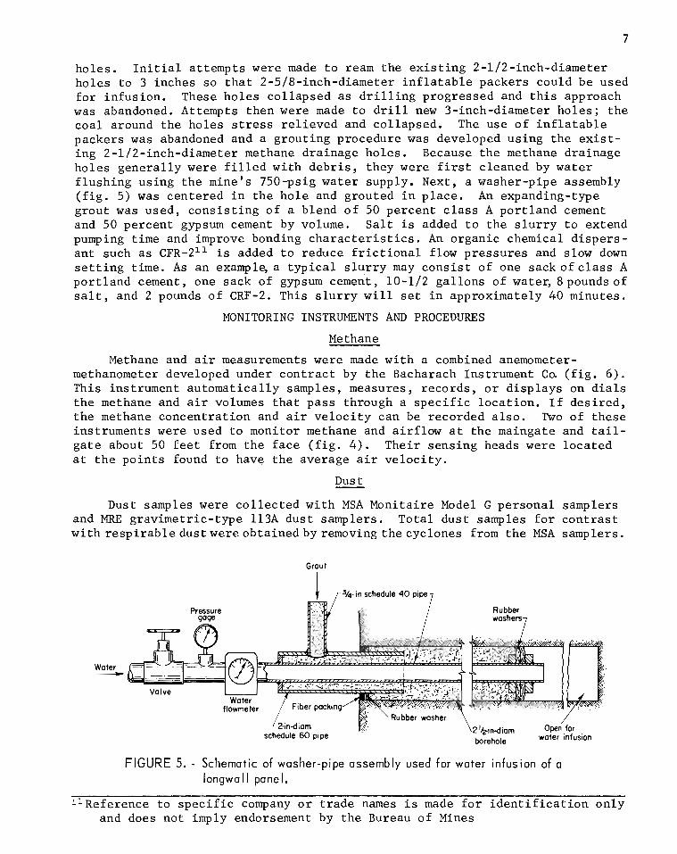
holes. Initial attempts were made to ream the existing 2-112-inch-diameter holes to 3 inches so that 2-518-inch-diameter inflatable packers could be used for infusion. These holes collapsed as drilling progressed and this approach was abandoned. Attempts then were made to drill new 3-inch-diameter holes; the coal around the holes stress relieved and collapsed. The use of inflatable packers was abandoned and a grouting procedure was developed using the exist- ing 2-112-inch-diameter methane drainage holes. Because the methane drainage holes generally were filled with debris, they were first cleaned by water flushing using the mine's 750-psig water supply. Next, a washer-pipe assembly (fig. 5) was centered in the hole and grouted in place. An expanding-type grout was used, consisting of a blend of 50 percent class A portland cement and 50 percent gypsum cement by volume. Salt is added to the slurry to extend pumping time and improve bonding characteristics. An organic chemical dispers- ant such as C F R - ~ ~ ~ is added to reduce frictional flow pressures and slow down setting time. As an example, a typical slurry may consist of one sackofclass A portland cement, one sack of gypsum cement, 10-112 gallons of water, 8pounds of salt, and 2 pounds of CRF-2. This slurry will set in approximately 40 minutes.
MONITORING INSTRUMENTS AND PROCEDURES
Methane
Methane and air measurements were made with a combined anemometer- methanometer developed under contract by the Bacharach Instrument Co. (fig. 6). This instrument automatically samples, measures, records, or displays on dials the methane and air volumes that pass through a specific location. If desired, the methane concentration and air velocity can be recorded also. Two of these instruments were used to monitor methane and airflow at the maingate and tail- gate about 50 feet from the face (fig. 4). Their sensing heads were located at the points found to have the average air velocity.
Dust - Dust samples were collected with MSA Monitaire Model G personal samplers
and MRE gravimetric-type 113A dust samplers. Total dust samples for contrast with r e sp i rab ledus twereob ta inedbyremoving thecyc lones from the MSA samplers.
Grout I
1 r34- in schedule 40 pipe
Woter - schedule 60 pipe
FIGURE 5. - Schematic of washer-pipe assembly used for water infusion of a longwall panel.
ll~eference to specific company or trade names is made for identification only and does not imply endorsement by the Bureau of Mines
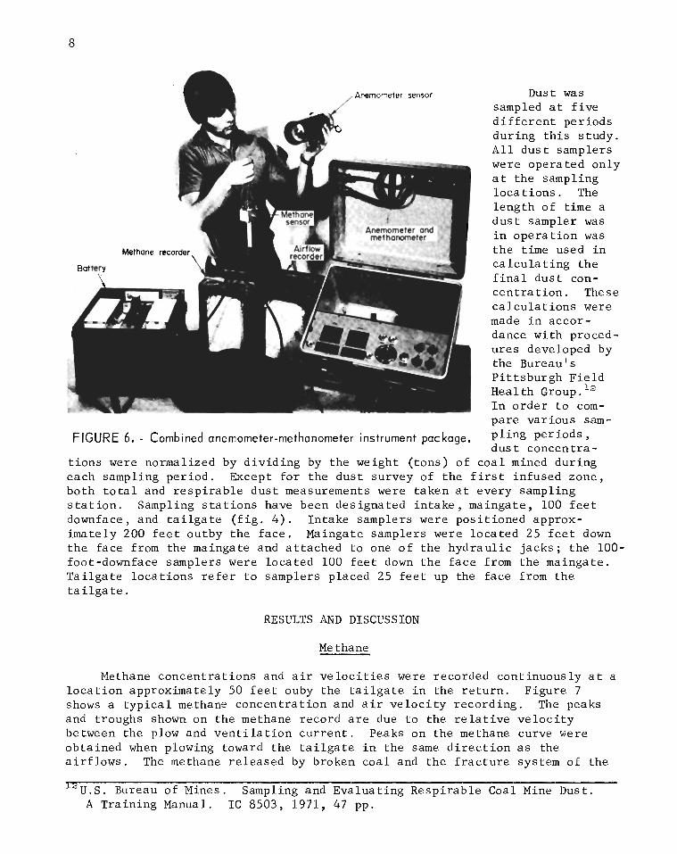
Dust w a s sampled a t f i v e d i f f e r e n t per iods dur ing t h i s s tudy . A l l d u s t samplers were operated on ly a t the sampling loca t ions . The length of t i m e a dus t sampler was i n ope ra t i on was t h e t i m e used i n c a l c u l a t i n g t h e f i n a l d u s t con- c e n t r a t i o n . These c a l c u l a t i o n s were made i n accor - dance with proced- u re s developed by the Bureau's P i t t sbu rgh F i e l d Heal th Group. l2 I n o rde r t o com- pare var ious sam-
FIGURE 6. - Combined anemometer-methanometer instrument package. pling periods dus t concen t r a -
t i ons were normalized by d iv id ing by the weight ( tons) of coa l mined dur ing each sampling per iod . Except fo r the dus t survey of t he f i r s t infused zone, both t o t a l and r e s p i r a b l e d u s t measurements were taken a t every sampling s t a t i o n . Sampling s t a t i o n s have been designated i n t a k e , maingate, 100 f e e t downface, and t a i l g a t e ( f i g . 4 ) . In take samplers were pos i t ioned approx- imately 200 f e e t outby the f ace . Maingate samplers were loca ted 25 f e e t down t h e face from the maingate and a t t ached t o one o f t h e hyd rau l i c jacks ; t he 100- foot-downface samplers were loca ted 100 f e e t down t h e f a c e from the maingate. T a i l g a t e l oca t ions r e f e r t o samplers placed 25 f e e t up the face from the t a i l g a t e .
RESULTS AND DISCUSSION
M e thane
Methane concent ra t ions and a i r v e l o c i t i e s were recorded cont inuously a t a l o c a t i o n approximately 50 f e e t ouby the t a i l g a t e i n the r e t u r n . Figure 7 shows a t y p i c a l methane concent ra t ion and a i r v e l o c i t y record ing . The peaks and troughs shown on the methane record a r e due t o the r e l a t i v e v e l o c i t y between the plow and v e n t i l a t i o n c u r r e n t . Peaks on the methane curve were obtained when plowing toward the t a i l g a t e i n t he same d i r e c t i o n a s the a i r f l o w s . The methane re leased by broken coa l and the f r a c t u r e system of the
n ~ . ~ . Bureau of Mines. Sampling and Evaluat ing Respi rab le Coal Mine Dust. A Tra in ing Manual. I C 8503, 1971, 47 pp.

pane l t r a v e l e d w i t h t h e plow and, consequently, t h e con- c e n t r a t i o n o f methane increased . The average speed o f t h e plow was 100 fpm ( f e e t p e r minute) and themeasured a i r v e l o c i t i e s i n t h e v i c i n i t y of t h e plow ranged from 400 t o 500 fpm. The t roughs on t h e methane curve were ob t a ined when t h e plow t r a v e l e d toward t h e maingate when t h e r e l a t i v e v e l o c i t y was g r e a t e s t s o t h e concen- t r a t i o n s of methane a r e lowest .
Examination of f i g u r e 7 shows t h a t t h e methane measured i n t h e immediate r e t u r n comes from t h e long- w a l l pane l . About 2 t o 3 hours a f t e r plowing ceased, t h e methane concen t r a t i on i n t h e a i r dropped t o about 0.05 pe rcen t methane--the l e v e l of methane i n t h e i n t a k e a i r . There appeared t o be no methane coming from t h e gob i n t h i s a r ea .
Taking an average methane concen t r a t i on of 0.5 pe rcen t dur ing plowing o p e r a t i o n s , an average a i r v e l o c i t y of 200 fpm, and a c r o s s - s e c t i o n ~ l a r e a of 90 square f e e t a t t h e measurement p o i n t , t h e volume flow of methane from t h e pane l would be 90 cfm (cubic f e e t p e r minute) . During a 6-hour plowing time about 2,000 tons of c o a l was mined. For t h i s mining pe r iod , methane was l i b e r a t e d a t a r a t e of 16.2 cubic f e e t pe r t o n of c o a l .
The back-and-for th movement o f t h e plow dur ing mining i n f luences t h e v e n t i l a t i o n c u r r e n t a s shown i n t h e a i r v e l o c i t y record ing i n f i g u r e 7. Note t h e f l u c - t u a t i o n s i n a i r v e l o c i t y dur ing plowing ope ra t i ons com- pared t o t h e v a r i a t i o n s a f t e r t h e plow i s s topped. Also, t h e envelope of t h e a i r v e l o c i t y record ing has peaks and t roughs t h a t c o r r e l a t e w i t h t h e peaks and t roughs o f t h e methane record ing . When t h e plow i s t r a v e l i n g toward t h e t a i l g a t e , a i r v e l o c i t y i n c r e a s e s , and dur ing t h i s time i n t e r v a l t h e methane concent ra - t i o n reaches i t s peak a l s o .
Water i n f u s i o n has no app rec i ab l e e f f e c t on meth- ane emission w h i l e mining t h e pane l . However, on ly a r e l a t i v e l y smal l volume of t h e pane l was i n fu sed nea r t h e maingate. To reduce methane flows f u r t h e r would r e q u i r e t h e emplacement o f a waterbank t h e wid th of t h e pane l . F igure 7 shows t h a t t h e r e i s some methane
~ ' v ~ & ~ T ~ o M E + H 9 \ N ~ ~ bleed-of f from t h e pane l a f t e r plowing s topped. The 100 fpm P c t f a c t t h a t methane concen t r a t i on maximums d i d no t
exceed 0 . 8 pe rcen t dur ing plowing demonstrates t h e e f f e c t i v e n e s s of t h e dra inage ho l e s d r i l l e d i n t o t h e
FIGURE 7, - Methane con- pane l dur ing development a s a methane c o n t r o l measure.
centrat ion and Dust - air ve loc i t y record ings. Before t h e i n f u s i o n t e s t s were conducted va r ious
d u s t c o n t r o l measures were used. During mining, t h e

f a c e was sprayed cont inuous ly a t approximately 90 po in t s , u s ing nozzles mounted on s p i l l p l a t e s . Water sprays a l s o were used a t t h e inby t r a n s f e r po in t ( f ace conveyor t o s t a g e l oade r ) and a t t h e e n t r y and e x i t of t h e coa l breaker . A w e t t i n g agent was metered i n t o t h e mine 's water supply t o i n c r e a s e t h e d u s t - suppress ion a b i l i t y of t h e wa te r . The outby t r a n s f e r p o i n t ( s t a g e l oade r t o conveyor b e l t ) was covered w i t h a hook cons t ruc t ed of angle i r o n and p l a s t i c s h e e t t o con ta in t h e a i r b o r n e dus t a t t h i s l oca t ion . These dus t c o n t r o l s were i n u se dur ing t h e f i r s t f ou r sampling pe r iods . During t h e f i f t h and f i n a l d u s t survey a d d i t i o n a l dus t c o n t r o l s w e r e u s e d a n d these w i l l be d i s c u s s e d i n con tex t .
The f i r s t survey was a base s tudy t o determine the d u s t concent ra t ions a t the va r ious sampling s t a t i o n s p r i o r t o i n fus ion . Dust samples were taken on the day s h i f t f o r 4 consecut ive days ( t a b l e 1 . ) With t h i s in format ion , an average d u s t concen t r a t i on was e s t a b l i s h e d f o r each sampling s t a t i o n .
TABLE 1. - Base l ine d u s t survey
I Dus t concen t r a t i on . /
In t ake : Mar. 8 . . . Mar. 9. . . Mar. 10 . . . Mar. 11 . . .
Average
Loca t ion and d a t e
T o t a l ' a l e n t 1 - tons r e s p i r a b l e
Maingate : Mar. 8 . . . 45.4 Mar. 9 . . . 59 .1 Mar. 10 . . . 60.8
mn /m3 ' c o a l I MRE equiv- production,.
Mar. 11. .. Average
T a i l g a t e : Mar. 8 . . . Mar. 9 . . . Mar. 0 . .
'Rock dus t voided samples.
66 .1 57 .9
(l)
129.8 88.5
Mar. 11 . . . Average
Because Pocahontas No. 3 c o a l i s h igh ly f r i a b l e and not very we t t ab l e , the dus t - suppress ion e f f e c t i v e n e s s of water was ques t i onab le . To answer t h i s ques t i on , a o n e - s h i f t s tudy was made which involved spray ing t h e f i r s t 100 f e e t of face wi th t h r e e equally-spaced f i r e nozz les . These nozzles were manually operated and used only when the plow was w i th in spray range. Thus a high volume of water was concentrated a t the plow where the concen t r a t i on of d u s t was g r e a t e s t . While the face was being sprayed i n t h i s manner, d u s t was being sampled a t t h r e e l o c a t i o n s - - a l l w i th in the f i r s t 100 f e e t of f ace . A s i g n i f i c a n t reduc t ion i n d u s t l e v e l s r e s u l t e d ( t a b l e 2 ) .
10.2 9 .6
.I
119.2 ,112 .5
2,376 2,104
13 .9 12.3
2,376 2,104

TABLE 2 . - F i r e nozzle t e s t
The f i r s t dus t survey of a n infused zone was made a s the face approached infus ion ho le A 1 ( t ab l e 3 ) . This was a 220-foot ho le which had been grouted t o a depth of 85 f e e t ( t a b l e 4 ) . Approximately 4,400 ga l lons of water were forced i n t o the coa l through t h i s ho le . Since the face was 450 f e e t long, only the f i r s t h a l f of the panel was adequately f looded. A schematic of the face a r e a ( f i g . 8 ) shows the l o c a t i o n of t he f a c e with r e spec t t o the in fus ion hole a t the beginning of each sampling s h i f t . The histograms ( f i g s . 9 and 10) show t o t a l and r e s p i r a b l e dus t concent ra t ion per ton a t the maingate and t a i l g a t e sampling s t a t i o n s and a dec l ine i n dus t conten t of the a i r a s t h e face neared the in fus ion h o l e . The unusa l ly low dus t concent ra t ions a t the maingate on March 30 were due i n p a r t to another experiment. On t h i s d a t e , b r a t t i c e c l o t h was placed a long the panl ine f o r 50 f e e t to keep dus t c rea ted by the plow from en te r ing a i r around the jacks.
FIGURE 8. - Face advance near borehole A l .
Maingate. . Downface :
70 f e e t . 75 f e e t .
Reduct ion from base average ,
percent
Dust concen- t r a t i o n , mg/m3
To ta l
3 1
44 3 7
To ta l
40.0
32.2 36.3
MRE equiv- a l e n t
r e s p i r a b l e 27
5 8 5 3
MRE equiv- a l e n t
r e s p i r a b l e 7.0
4 . 0 4 .5

TABLE 3 . - Dust su rvey ; borehole A 1
I Dust c o n c e n t r a t i o n , 1 Loca t ion and d a t e
I n t a k e : Mar. 28 . . . Mar. 30 . . . Mar. 31. . . Apr. 3 . . . Apr. 4 . . .
Mainga t e : Mar. 28 . . . Mar. 30 . . .
. . Mar. 3 1 . Apr. 3 . . . Apr. 4 . . .
Ta i l g a t e : Mar. 28 . . . Mar. 30 . . .
. . Mar. 31. Apr. 3 . . .
- 1 MRE equ iv- p r o d u c t i o n , To t a 1 a l e n t
r e s i r a b l e
Apr. 4 . . . ) 53.9 1 6 . 6 1 1 ,900 'NO samples t a k e n . " p a r t - t i m e work.
Table 4 . - Water i n f u s i o n d a t a
Bore- h o l e
Water ) Amount of
A 1
wa te r Depth, f e e t
220
The normalized c o n c e n t r a t i o n s (mg/m3/ton o f c o a l ) t aken when t h e f a c e was 10 f e e t from t h e i n f u s i o n h o l e compared wi th t h e b a s e l i n e su rvey shows a
Grouted p a r t ,
gpm 18 .2
pronounced r e d u c t i o n i n a i r b o r n e d u s t ( t a b l e 5 . ) This r e d u c t i o n was g r e a t e s t a t t h e maingate l o c a t i o n s t h a t c o l l e c t e d d u s t produced mainly from t h e in fused p o r t i o n o f the f a c e .
4
Water p r e s s u r e , average
f e e t 85
ga 1 lons 4,368
TABLE 5 . - Percen t o f d u s t r e d u c t i o n ; borehole ~ 1 '
ps i g 709
Loca t ion 1 Dust r educed , p e r c e n t
T a i l g a t e . . . . . . . ( 47 1 40 ma ace: 10 f e e t from h o l e A l .
Maingate. . . . . . . T o t a l
69 MRE e q u i v a l e n t r e s p i r a b l e
79

Maingate
March - 1 - April I -
TIME, days
FIGURE 9. - T o t a l dust histograms; borehole A l .
-
-
-
-
-
-
TIME, days
I I I I 1 ' 1
Tailgate
..... ..... ..... ..... ..... .......... ..... ..... ..... ..... .....
0.014
3 n' < .012- rn
J a
8 ,lo- b
March - April T
..... ..... ..... 28 129 1 1 . ~ ' 1 3 1
March -
1 1 1 1 1 1 1
Maingate
The n e x t d u s t s u r v e y took p l a c e a s t h e f a c e approached t h e second i n f u s e d h o l e A2. Th i s h o l e was 220 f e e t d e e p , g rou ted t o 145 f e e t , and i n f u s e d v i t h 5 ,800 g a l l o n s of wa te r ( t a b l e 4 ) . Dust was sampled o n t h r e e s h i f t s . Samplers were p laced a t i n t a k e , main- ga t e , and t a i lga t e sampl ing s t a t i o n s . During sampl ing i n t e r v a l s , hazardous roof c o n d i t i o n s s lowed produc- t i o n t o a b o u t o n e - f o u r t h normal. For t h i s r e a s o n , i t was n o t p o s s i b l e t o a s c e r t a i n whether t h e low d u s t l e v e l s were due e n t i r e l y t o low p r o d u c t i o n o r i n p a r t t o w a t e r i n f u s i o n .
1 i 2 ' 3 I 4
April -
The samples c o l l e c t e d d u r i n g t h i s p e r i o d do show t h a t a t low product i o n r a t e s t h e d u s t c o n c e n t r a t i o n approaches a c o n s t a n t l e v e l a l l a l o n g t h e f a c e ( t a b l e 6 . )
A f i n a l d u s t su rvey ( t a b l e 7 ) was made a s the f a c e receded from a n a r e a i n f u s e d through two h o l e s -- A3 and A4 ( t a b l e 4 ) . The f i r s t h o l e , A3, was 120 f e e t d e e p , g rou ted t o 40 f e e t , and in fused w i t h 1 ,000 g a l - l o n s o f w a t e r . Hole A4 was l o c a t e d 20 f e e t outby A3 and was i n f u s e d wi th 4 ,500 g a l - l o n s . This h o l e was 80 f e e t deep and g rou ted t o 50 f e e t . A schemat ic o f the f a c e a r e a d u r i n g t h e sampl ing c y c l e i s shown i n f i g u r e 11. A s t h e
FIGURE 10 . - Respirable dust histograms; borehole A l . f a c e receded from t h e i n f u s e d zone , t h e h i s tograms ( f i g s . 12-13) show t h a t t h e
d u s t c o n c e n t r a t i o n i n c r e a s e d . T h i s same t r e n d a l s o may be s e e n i n t h e t o t a l d u s t t a i l g a t e samples , w i t h one e x c e p t i o n ( t a b l e 7 ) . On t h e t h i r d day o f Sam- p l i n g , t h e measured t o t a l d u s t a t the t a i l g a t e , when normal ized , was lower t h a n t h a t a t t h e maingate and 100- foo t downface l o c a t i o n s . There was no
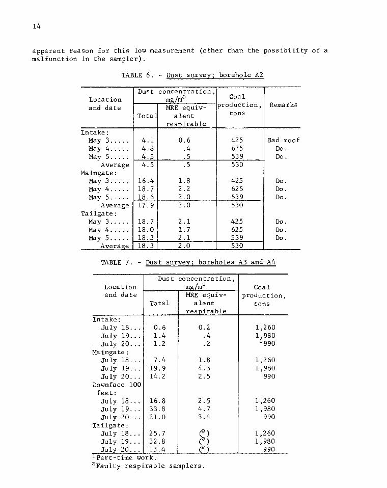
apparen t reason f o r t h i s low measurement (o ther than the p o s s i b i l i t y of a malfunct ion i n t he sampler) .
TABLE 6 . - Dust survey; borehole A2
TABLE 7. - Dust survey; boreholes A3 and A4
I Dust concen t r a t i on ,
Locat ion and d a t e
I n t a k e : May 3 . . . . . May 4 . . . . . May 5 . . . . .
Average Maingate:
May 3 . . . . . May 4 . . . . . May 5 . . . . .
Average Ta i lga t e :
May 3 . . . . . May 4 . . . . . May 5 . . . . .
Average
Locat ion and d a t e
To ta l a l e n t
Coa 1 product ion ,
tons
42 5 625 53 9 530
425 62 5 53 9 530
42 5 625 539 530
Remarks
Bad roof Do. Do.
Do. Do. Do.
Do. Do. Do.
Dus t concen t r a t i on , m /m3
J u l y 18. . . J u l y 19 . . . Ju ly 20 . . .
To t a 1
4 . 1 4 .8 4 .5 4 .5
16 .4 18.7 18 .6 17.9
18 .7 18 .0 18 .3 18 .3
I n t a k e :
Ma inga t e : July 18 . . . July 19. . . July 20 . . .
Downface 100 f e e t : J u l y 18 . . . J u l y 1 9 . . . July 20 . . .
T a i l g a t e : J u l y 18. . . J u l y 1 9 . . . J u l y 20. . .
'par t - t ime w
- zE equiv- a l e n t
r e s p i r a b l e
0 .6 . 4 . 5 . 5
1 .8 2 .2 2 .0 2 . 0
2 . 1 1 .7 2 . 1 2 . 0
r e s p i r a b l e
" ~ a u l t ~ r e s p ) r k . . rab le samplers .
Coa 1 product ion ,
tons

F I G U R E 1 1. - Face advance in area of boreholes A3 and A4.
0.025
Maingate
0.020 i- 0 . 0 0 4
Maingate
0.003
-
I I
100 ft down- face
...... ........... ..... ...... ..... ...... ..... ...... ........... ..*.. ...... ..... ..........
TIME, days TI ME, days
............ .......... -.:.:.:.:.' -. ......... :.:.:.:.:.. - ........... :....-.-... ........:. .......... ........... ........... ............ .......... ........... 55...1-. .........
18 1 19 120
July 4 b
-
-
-
FIGURE 12. - Total dust histograms; bore- FIGURE 13. - Respirable dust histograms; holes A3 and A4. boreholes A3 and A4.
At t h e t ime o f t h i s sampling p e r i o d , a d d i t i o n a l d u s t c o n t r o l s had been i n c o r p o r a t e d i n t o the s e c t i o n . Foam was being a p p l i e d a t t h e inby t r a n s f e r p o i n t and a t the e n t r a n c e of t h e c o a l b reaker . Watersprays had been mounted on t h e plow and were o p e r a t i n g . The s p r a y s were mounted v e r t i c a l l y , n ine on each s i d e of the plow. These d u s t c o n t r o l s r e q u i r e d about 30,000 g a l l o n s of wa te r p e r s h i f t . While t h e d u s t samples were being c o l l e c t e d , t h e f a c e passed through a n a r e a in fused wi th abou t 5,500 g a l l o n s o f w a t e r . The r a t i o o f i n f u s e d t o s p r a y wate r was abou t 1 t o 5 . Even w i t h t h i s h i g h r a t i o t h e e f f e c t
1 8 1 1 9 120 Luly J
I I 100 f t down-
...... m ..... ...... ..... ...... ........... ..... ........... ...... ..... ...... ..... ...... ..... ...... ..... ...... ..... ...... ........... .......... ........... ......... ............ .......... ............ ...........
.......
mm
.....
t ........... ............... .................. ............... .................. ................................. ............... .................. ............... .................. ............... .................. ............... .................. ............... .................. ............... ................................. .................. ............... .................. ............... .................. ............... .................. ............... .................. ............... .................. ............... .................. ............... ................ ................. .................. ............... .................. ............... ............... .................. ................. &...

of i n f u s i o n was measurab le , a s shown by the h i s tograms . A comparison was made between t h e normalized d u s t c o n c e n t r a t i o n s t aken on t h e f i r s t sampl ing day o f t h i s pe r iod and t h e b a s e l i n e normalized c o n c e n t r a t i o n s . The r e s u l t s a r e found i n t a b l e 8 .
TABLE 8 . - P e r c e n t o f d u s t r e d u c t i o n ; boreho les A3 and A4
A comparison o f t a b l e s 8 and 5 shows t h a t d u s t c o n c e n t r a t i o n d e c l i n e a t t h e maingate was approx imate ly t h e same i n bo th s u r v e y s . A t t h e t a i l g a t e , however, t h e comparison shows a s l i g h t l y g r e a t e r d e c l i n e i n a i r b o r n e d u s t d u r i n g t h e l a s t su rvey . A t t h i s l o c a t i o n , t a b l e 8 shows a n a d d i t i o n a l r educ- t i o n o f 15 p e r c e n t f o r r e s p i r a b l e d u s t and a n a d d i t i o n a l 24 p e r c e n t f o r t o t a l d u s t o v e r t h a t i n t a b l e 5 . The most i n t e r e s t i n g f i n d i n g h e r e was t h a t wa te r i n f u s i o n a l o n e was more e f f e c t i v e i n s u p p r e s s i n g d u s t t h a n a l l t h e o t h e r d u s t c o n t r o l s noted above.
- - - - -
~ o c a t ion
Maingate . . . . . . . T a i l g a t e . . . . . . .
The Pocahontas No. 3 coalbed i s h i g h l y f r a c t u r e d and f r i a b l e and a p p a r - e n t l y t h e bu lk of t h e d u s t observed d u r i n g mining i s i n h e r e n t t o t h e coalbed. I f t h e d u s t i n t h e f r a c t u r e system can be wet ted b e f o r e t h e c o a l i s mined d u s t c a n be c o n t r o l l e d to, a c c e p t a b l e l e v e l s . Water i n f u s i o n i s a n e f f e c t i v e d u s t s u p p r e s s a n t i n t h e Pocahontas No. 3 coalbed because o n l y a s m a l l f r a c t i o n of t h e d u s t i s genera ted by b reak ing blocks o f s o l i d c o a l .
CONCLUSIONS
Incons i s t e n t measurement.
- - - -
Dust reduced, p e r c e n t
Water i n f u s i o n of longwal l pane l s i n t h e Pocahontas No. 3 coa lbed i s a n e f f e c t i v e and e f f i c i e n t means of s u p p r e s s i n g t o t a l and r e s p i r a b l e d u s t . Although t h e s p r a y system on the plow does suppress a i r b o r n e d u s t , i t i s n o t a s e f f e c t i v e a s water i n f u s i o n . The b u l k of d u s t observed d u r i n g mining i s i n h e r e n t t o t h e coalbed and w e t t i n g t h i s d u s t b e f o r e mining p reven t s i t from becoming a i r b o r n e . The e f f e c t i v e n e s s o f wa te r i n f u s i o n can be i n c r e a s e d by i n f u s i n g t h e pane l from bo th s i d e s .
T o t a l 78 62
Because l e s s t h a n one-ha l f of t h e pane l n e a r t h e maingate was i n f u s e d , methane l i b e r a t i o n from t h e longwal l f a c e was n o t a f f e c t e d . The d e t e r m i n a t i o n o f t h e e f f e c t of water i n f u s i o n on methane r e q u i r e s t h e whole f a c e t o be i n f u s e d . The l e v e l s o f methane observed d u r i n g plowing o p e r a t i o n s i n d i c a t e t h a t methane d r a i n a g e h o l e s d r i l l e d i n t o t h e pane l on development a r e e f f e c - t i v e i n p redra i n i n g me thane .
MRE e q u i v a l e n t r e s p i r a b l e 68 1