method 0011: sampling for selected aldehyde and ketone
TRANSCRIPT

CD-ROM 0011 - 1 Revision 0December 1996
METHOD 0011
SAMPLING FOR SELECTED ALDEHYDE AND KETONE EMISSIONSFROM STATIONARY SOURCES
1.0 SCOPE AND APPLICATION
1.1 This method is applicable to the determination of Destruction and Removal Efficiency(DRE) of the analytes listed in the following table:
Analyte CAS No.a
Formaldehyde 50-00-0Acetaldehye 75-07-0Acetophenone 98-86-2Isophorone 78-59-1Propionaldehyde 123-38-6
Chemical Abstract Service Registry Number a
This method has been applied specifically to the above analytes. Many laboratories haveextended method application to other aldehydes and ketones. This method is possibly applicableto other aldehydes and ketones from stationary sources as specified in the regulations. However,this method is not applicable to quinone (CAS No. 106-51-4), acrolein (CAS No. 107-02-08), methylethyl ketone (CAS No. 78-93-3), and methyl isobutyl ketone (CAS No. 108-10-1).
1.2 The detection limit for a 30 ft (849 L) sample over a 1 hour sampling period may be as3
low as 10 ppbv for acetophenone and isophorone, 60 ppbv for propionaldehyde, 40 ppbv foracetaldehyde, and 90 ppbv for formaldehyde. Because the derivatization reaction is based on theformation of an equilibrium state between reactants and products, for some compounds quantitativerecoveries may not be achieved until the concentration exceeds 200 ppbv.
1.3 This method is restricted to use by, or under the close supervision of, analystsexperienced in sampling organic compounds in air. Each analyst must demonstrate the ability togenerate acceptable results with this method.
2.0 SUMMARY OF METHOD
Gaseous and particulate pollutants are withdrawn isokinetically from an emission source andare collected in aqueous acidic 2,4-dinitrophenylhydrazine. Formaldehyde present in the emissionsreacts with the 2,4-dinitrophenylhydrazine to form the formaldehyde dinitrophenylhydrazonederivative. The dinitrophenylhydrazone derivative is extracted, solvent-exchanged, concentrated,and then analyzed by high performance liquid chromatography (HPLC) according to Method 8315or other appropriate technique.

CD-ROM 0011 - 2 Revision 0December 1996
3.0 INTERFERENCES
3.1 A decomposition product of 2,4-dinitrophenylhydrazine, 2,4-dinitroaniline, can be ananalytical interferant if concentrations are high. The 2,4-dinitroaniline can coelute with the 2,4-dinitrophenylhydrazone of formaldehyde under the high performance liquid chromatographyconditions used for the analysis. High concentrations of highly oxygenated compounds, especiallyacetone, that have the same retention time or nearly the same retention time as thedinitrophenylhydrazone of formaldehyde, and that also absorb at 360 nm, will interfere with theanalysis.
3.2 Formaldehyde, acetone, and 2,4-dinitroaniline contamination of the aqueous acidic 2,4-dinitrophenylhydrazine (DNPH) reagent is frequently encountered. The reagent must be preparedwithin five days of use in the field and must be stored in an uncontaminated environment both beforeand after sampling, in order to minimize blank problems. Some concentration of acetonecontamination is unavoidable, because acetone is ubiquitous in laboratory and field operations.However, the acetone contamination must be minimized.
3.3 Dimethylolurea creates a slight positive interference; and hexamethylenetetramine andparaformaldehyde significantly interfere with the determination of formaldehyde. These compoundscan decompose in the acidic reagent used to collect the sample to form formaldehyde;
3.4 Tolualdehyde interferes with the determination of acetophenone because they coelutechromatographically;
3.5 High levels of nitrogen dioxide can interfere by consuming all of the reagent.
4.0 APPARATUS AND MATERIALS
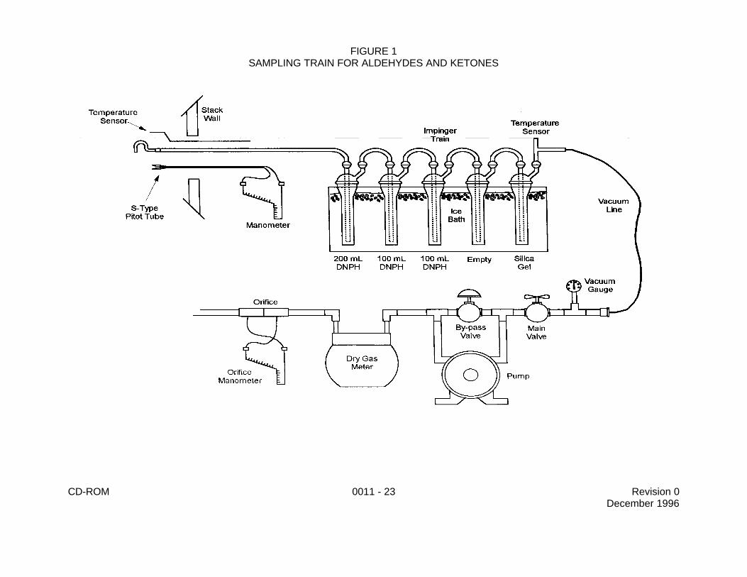
4.1 This sampling train configuration is adapted from Method 5 (see Ref. 1) procedures. Thesampling train consists of the following components: Probe nozzle, pitot tube, differential pressuregauge, metering system, barometer, and gas density determination equipment. A schematic of thesampling train is shown in Figure 1.
4.1.1 Probe Nozzle - The probe nozzle shall be quartz or glass with sharp, tapered(30E angle) leading edge. The taper shall be on the outside to preserve a constant innerdiameter. The nozzle shall be buttonhook or elbow design. A range of nozzle sizes suitablefor isokinetic sampling should be available in increments of 0.16 cm (1/16 in.), e.g., 0.32 to1.27 cm (1/8 to ½ in.), or larger if higher volume sampling trains are used. Each nozzle shallbe calibrated according to the procedures outlined in Sec. 8.1.
4.1.2 Probe Liner - Borosilicate glass or quartz shall be used for the probe liner. Thetester should not allow the temperature in the probe to exceed 120 ±14EC (248 ±25EF).
4.1.3 Pitot Tube - The pitot tube shall be Type S or any other appropriate device. TheType S pitot tube shall be made of metal tubing (e.g., stainless steel). It is recommended thatthe external tubing diameter be between 0.48 and 0.95 cm. There shall be an equal distancefrom the base of each leg to its face-opening plane; it is recommended that this distance bebetween 1.05 and 1.50 times the external tubing diameter. The face openings of the pitot tubeshall, preferably, be aligned but slight misalignments of the openings are permissible. The

CD-ROM 0011 - 3 Revision 0December 1996
Type S pitot tube assembly shall have a known coefficient, determined as outlined in Method2 (see Ref. 1). The pitot tube shall be attached to the probe to allow constant monitoring ofthe stack gas velocity. The impact (high pressure) opening plane of the pitot tube shall beeven with or above the nozzle entry plane (see Method 2) during sampling.
4.1.4 Differential Pressure Gauge - The differential pressure gauge shall be an inclinedmanometer or equivalent device as described in Method 2. One manometer shall be used forvelocity-head readings and the other for orifice differential pressure readings.
4.1.5 Impingers - The sampling train requires a minimum of five impingers, connectedas shown in Figure 1, with ground glass (or equivalent) vacuum-tight fittings. For the first,third, fourth, and fifth impingers, use the Greenburg-Smith design, modified by replacing thetip with a 1.27 cm (½ in) inside diameter glass tube extending to 1.27 cm (½ in.) from thebottom of the flask. For the second impinger, use a Greenburg-Smith impinger with thestandard tip. Place a thermometer capable of measuring temperature to within 1EC (2EF) atthe outlet of the fifth impinger for monitoring purposes.
4.1.6 Metering System - The necessary components of the metering system are avacuum gauge, leak-free pump, thermometers capable of measuring temperature within 3EC(5.4EF), dry-gas meter capable of measuring volume to within 1%, and related equipment asshown in Figure 1. At a minimum, the pump should be capable of 4 cfm free flow, and the drygas meter should have a recording capacity of 0-999.9 cu ft with a resolution of 0.005 cu ft.Other metering systems may be used which are capable of maintaining sample volumes towithin 2%. The metering system may be used in conjunction with a pitot tube to enablechecks of isokinetic sampling rates.
4.1.7 Barometer - The barometer may be mercury, aneroid, or other barometer capableof measuring atmospheric pressure to within 2.5 mm Hg (0.1 in. Hg). In many cases, thebarometric reading may be obtained from a nearby National Weather Service Station, in whichcase the station value (which is the absolute barometric pressure) is requested and anadjustment for elevation differences between the weather station and sampling point is appliedat a rate of minus 2.5 mm Hg (0.1 in. Hg) per 30 m (100 ft) elevation increase (vice versa forelevation decrease).
4.1.8 Gas Density Determination Equipment - The gas density determinationequipment includes a temperature sensor and pressure gauge (as described in Method 2) andgas analyzer, if necessary (an Orsat of Fyrite type combustion gas analyzer, or equivalent.For analyzer maintenance and operation procedures, follow the instructions recommendedby the manufacturer). The temperature sensor ideally should be permanently attached to thepitot tube or sampling probe in a fixed configuration such that the tip of the sensor extendsbeyond the leading edge of the probe sheath and does not touch any metal. Alternatively, thesensor may be attached just prior to use in the field. Note, however, that if the temperaturesensor is attached in the field, the sensor must be placed in an interference-free arrangementwith respect to the Type S pitot tube openings (see Method 2). As a second alternative, if adifference of no more than 1% in the average velocity measurement is to be introduced, thetemperature gauge need not be attached to the probe or pitot tube.
4.2 Sample Recovery
4.2.1 Probe Liner - Probe nozzle and brushes; Teflon® bristle brushes with stainlesssteel wire handles are required. The probe brush shall have extensions of stainless steel,
CD-ROM 0011 - 4 Revision 0December 1996
Teflon®, or inert material at least as long as the probe. The brushes shall be properly sizedand shaped to brush out the probe liner, the probe nozzle, and the impingers.
4.2.2 Wash Bottles - Three wash bottles are required. Teflon® or glass wash bottlesare recommended. Polyethylene wash bottles should not be used because organiccontaminants may be extracted by exposure to the organic solvents used for sample recovery.
4.2.3 Graduated Cylinder and/or Balance - A graduated cylinder or balance is requiredto measure condensed water to the nearest 1 mL or 1 g. Graduated cylinders shall havedivisions not greater than 2 mL. Laboratory balances capable of weighing to ±0.5 g arerequired.
4.2.4 Amber Glass Storage Containers - One-liter wide-mouth amber flint glass bottleswith Teflon®-lined caps are required to store impinger water samples. The bottles must besealed with Teflon® tape.
4.2.5 Rubber Policeman and Funnel - A rubber policeman and funnel are required toaid in the transfer of materials into and out of containers in the field.
4.3 Reagent Preparation
4.3.1 Bottles/Caps - Amber 1 - 4 L bottles with Teflon®-lined caps are required forstoring cleaned DNPH solution. Additional 4-L bottles are required to collect waste organicsolvents.
4.3.2 Large Glass Container - At least one large glass (8 to 16 L) is required for mixingthe aqueous acidic DNPH solution.
4.3.3 Stir Plate/Large Stir Bars/Stir Bar Retriever - A magnetic stir plate and large stirbar are required for the mixing of the aqueous acidic DNPH solution. A stir bar retriever isneeded for removing the stir bar from the large container holding the DNPH solution.
4.3.4 Buchner Filter/Filter Flask/Filter Paper - A large filter flask (2-4 L) with a buchnerfilter, appropriate rubber stopper, filter paper, and connecting tubing are required for filteringthe aqueous acidic DNPH solution prior to cleaning.
4.3.5 Separatory Funnel - At least one large separatory funnel (2 L) is required forcleaning the DNPH prior to use.
4.3.6 Beakers - Beakers (150 mL, 250 mL, and 400 mL) are useful forholding/measuring organic liquids when cleaning the aqueous acidic DNPH solution and forweighing DNPH crystals.
4.3.7 Funnels - At least one large funnel is needed for pouring the aqueous acidicDNPH into the separatory funnel.
4.3.8 Graduated Cylinders - At least one large graduated cylinder (1 to 2 L) is requiredfor measuring organic-free reagent water and acid when preparing the DNPH solution.
4.3.9 Top-loading Balance - A one-place top loading balance is needed for weighingout the DNPH crystals used to prepare the aqueous acidic DNPH solution.

CD-ROM 0011 - 5 Revision 0December 1996
4.3.10 Spatulas - Spatulas are needed for weighing out DNPH when preparing theaqueous DNPH solution.
4.4 Crushed Ice - Quantities of crushed ice ranging from 10-50 lb may be necessary duringa sampling run, depending upon ambient temperature. Samples which have been taken must bestored and shipped cold; sufficient ice for this purpose must be allowed.
5.0 REAGENTS
5.1 Reagent Grade Chemicals - Reagent grade inorganic chemicals shall be used in alltests. Unless otherwise indicated, it is intended that all reagents shall conform to the specificationsof the Committee on Analytical Reagents of the American Chemical Society, where suchspecifications are available. Other grades may be used, provided it is first ascertained that thereagent is of sufficiently high purity to permit its use without lessening the accuracy of thedetermination.
5.2 Organic-free Reagent Water - All references to water in this method refer to organic-freereagent water, as defined in Chapter One.
5.3 Silica Gel - Silica gel shall be indicating type, 6-16 mesh. If the silica gel has been usedpreviously, dry at 175EC (350EF) for 2 hours before using. New silica gel may be used as received.Alternatively, other types of desiccants (equivalent or better) may be used.
5.4 2,4-Dinitrophenylhydrazine (DNPH), [2,4-(0 N) C H ]NHNH - The quantity of water may2 2 6 3 2
vary from 10 to 30%.
5.4.1 The 2,4-dinitrophenylhydrazine reagent must be prepared in the laboratory withinfive days of sampling use in the field. Preparation of DNPH can also be done in the field, withconsideration of appropriate procedures required for safe handling of solvent in the field.When a container of prepared DNPH reagent is opened in the field, the contents of theopened container should be used within 48 hours. All laboratory glassware must be washedwith detergent and water and rinsed with water, methanol, and methylene chloride prior to use.
NOTE: DNPH crystals and DNPH solution are potential carcinogens and should behandled with plastic gloves at all times, with prompt and extensive use ofrunning water in case of skin exposure.
5.4.2 Preparation of Aqueous Acidic DNPH Derivatizing Reagent - Each batch ofDNPH reagent should be prepared and purified within five days of sampling, according to theprocedure described below.
NOTE: Reagent bottles for storage of cleaned DNPH derivatizing solution must berinsed with acetonitrile and dried before use. Baked glassware is notessential for preparation of DNPH reagent. The glassware must not berinsed with acetone or an unacceptable concentration of acetonecontamination will be introduced. If field preparation of DNPH is performed,caution must be exercised in avoiding acetone contamination.
5.4.2.1 Place an 8 L container under a fume hood on a magnetic stirrer. Adda large stir bar and fill the container half full of organic-free reagent water. Save the

CD-ROM 0011 - 6 Revision 0December 1996
empty bottle from the organic-free reagent water. Start the stirring bar and adjust the stirrate to be as fast as possible. Using a graduated cylinder, measure 1.4 L ofconcentrated hydrochloric acid. Slowly pour the acid into the stirring water. Fumes maybe generated and the water may become warm. Weigh the DNPH crystals to ±0.1 g(see Table 1 for approximate amounts) and add to the stirring acid solution. Fill the 8L container to the 8 L mark with organic-free reagent water and stir overnight. If all ofthe DNPH crystals have dissolved overnight, add additional DNPH and stir for two morehours. Continue the process of adding DNPH with additional stirring until a saturatedsolution has been formed, as evidenced by the presence of visible crystals aftercontinued stirring. Filter the DNPH solution using vacuum filtration. Gravity filtration maybe used, but a much longer time is required. Store the filtered solution in an amberbottle at room temperature.
5.4.2.2 Within five days of proposed use, place about 1.6 L of the DNPHreagent in a 2 L separatory funnel. Add approximately 200 mL of methylene chlorideand stopper the funnel. Wrap the stopper of the funnel with paper towels to absorb anyleakage. Invert and vent the funnel. Then shake vigorously for 3 minutes. Initially, thefunnel should be vented frequently (every 10 - 15 seconds). After the layers haveseparated, discard the lower (organic) layer.
5.4.2.3 Extract the DNPH a second time with methylene chloride and finally withcyclohexane. When the cyclohexane layer has separated from the DNPH reagent, thecyclohexane layer will be the top layer in the separatory funnel. Drain the lower layer(the cleaned extracted DNPH reagent solution) into an amber bottle that has been rinsedwith acetonitrile and allowed to dry.
5.4.3 DNPH Reagent Check - Take two aliquots of the extracted DNPH reagent. Thesize of the aliquots is dependent upon the exact sampling procedure used, but 100 mL isreasonably representative. Analyze one aliquot of the reagent according to Sec. 7 of Method8315 as a Quality Control check to ensure that the background in the reagent is acceptablefor field use. Save the other aliquot of aqueous acidic DNPH for use as a method blank whenthe analysis is performed. The reagent is acceptable for use if the background meets the AIC(Acceptable Impurity Concentration) as specified in Sec. 5.4.5.
5.4.4 Shipment to the Field - Tightly cap the bottle containing extracted DNPH reagentusing a Teflon®-lined cap. Seal the bottle with Teflon® tape. After the bottle is labeled, thebottle may be placed in a friction-top can (paint can or equivalent) containing a 1-2 inch layerof granulated charcoal and stored at ambient temperature until use.
5.4.4.1 If the DNPH reagent has passed the Quality Control criteria, the reagentmay be packaged to meet necessary shipping requirements and sent to the samplingarea. If the Quality Control criteria are not met, the reagent solution may be re-extractedor the solution may be re-prepared and the extraction sequence repeated.
5.4.4.2 If the DNPH reagent is not used in the field within five days ofextraction, an aliquot may be taken and analyzed as described in Sec. 7 of Method8315. If the reagent meets the Quality Control requirements, the reagent may be used.If the reagent does not meet the Quality Control requirements, the reagent must bediscarded and new reagent must be prepared and tested.

CD-ROM 0011 - 7 Revision 0December 1996
5.4.5 Calculation of Acceptable Concentrations of Impurities in DNPH Reagent - Theacceptable impurity concentration (AIC, µg/mL) is calculated from the expected analyteconcentration in the sampled gas (EAC, ppbv), the volume of air that will be sampled atstandard conditions (SVOL, L), the formula weight of the analyte (FW, g/mol), and the volumeof DNPH reagent that will be used in the impingers (RVOL, mL):
AIC = 0.1 x [EAC x SVOL x FW/24.4 x (FW + 180)/FW](RVOL/1,000)
where:
0.1 is the acceptable contaminant concentration, 24.4 is a factor relating ppbv to g/L, 180 is a factor relating underivatized to derivatized analyte, and1,000 is a unit conversion factor.
5.4.6 Disposal of Excess DNPH Reagent - Excess DNPH reagent may be returned tothe laboratory and recycled or treated as aqueous waste for disposal purposes. 2,4-Dinitrophenylhydrazine is a flammable solid when dry, so water should not be evaporated fromthe solution of the reagent.
5.5 Field Spike Standard Preparation - To prepare a formaldehyde field spiking standard at4010 mg/L, use a 500 µL syringe to transfer 0.5 mL of 37% by weight of formaldehyde (401 g/L) toa 50 mL volumetric flask containing approximately 40 mL of methanol. Dilute to 50 mL withmethanol.
5.6 Hydrochloric Acid, HCl - Reagent grade hydrochloric acid (approximately 12N) is requiredfor acidifying the aqueous DNPH solution.
5.7 Methylene Chloride, CH Cl - Methylene chloride (suitable for residue and pesticide2 2
analysis, GC/MS, HPLC, GC, Spectrophotometry or equivalent) is required for cleaning the aqueousacidic DNPH solution, rinsing glassware, and recovery of sample trains.
5.8 Cyclohexane, C H - Cyclohexane (HPLC grade) is required for cleaning the aqueous6 12
acidic DNPH solution.
NOTE: Do not use spectroanalyzed grades of cyclohexane if this sampling methodologyis extended to aldehydes and ketones with four or more carbon atoms.
5.9 Methanol, CH OH - Methanol (HPLC grade or equivalent) is necessary for rinsing3
glassware.
5.10 Acetonitrile, CH CN - Acetonitrile (HPLC grade or equivalent) is required for rinsing3
glassware.
5.11 Formaldehyde, HCHO - Formaldehyde (analytical reagent grade, or equivalent) isrequired for preparation of standards. If other aldehydes or ketones are used, analytical reagentgrade, or equivalent, is required.

CD-ROM 0011 - 8 Revision 0December 1996
6.0 SAMPLE COLLECTION, PRESERVATION, AND HANDLING
6.1 Because of the complexity of this method, field personnel should be trained in andexperienced with the test procedures in order to obtain reliable results.
6.2 Laboratory Preparation
6.2.1 All the components shall be maintained and calibrated according to theprocedure described in APTD-0576 (Air Pollution Technical Document, see references),unless otherwise specified.
6.2.2 Weigh several 200 to 300 g portions of silica gel in airtight containers to thenearest 0.5 g. Record on each container the total weight of the silica gel plus containers. Asan alternative to preweighing the silica gel, it may instead be weighed directly in the impingeror sampling holder just prior to train assembly.
6.3 Preliminary Field Determinations
6.3.1 Select the sampling site and the minimum number of sampling points accordingto Method 1 (see Ref. 1) or other relevant criteria. Determine the stack pressure, temperature,and range of velocity heads using Method 2. A leak-check of the pitot lines according toMethod 2 must be performed. Determine the stack gas moisture content using ApproximationMethod 4 (see Ref. 1) or its alternatives to establish estimates of isokinetic sampling-ratesettings. Determine the stack gas dry molecular weight, as described in Method 2. Ifintegrated Method 3 (see Ref. 1) sampling is used for molecular weight determination, theintegrated bag sample shall be taken simultaneously with, and for the same total length of timeas, the sample run.
6.3.2 Select a nozzle size based on the range of velocity heads so that it is notnecessary to change the nozzle size in order to maintain isokinetic sampling rates below 28L/min (1.0 cfm). During the run, do not change the nozzle. Ensure that the proper differentialpressure gauge is chosen for the range of velocity heads encountered (see Sec. 2 of Method2).
6.3.3 Select a suitable probe liner and probe length so that all traverse points can besampled. For large stacks, to reduce the length of the probe, consider sampling from oppositesides of the stack.
6.3.4 A minimum of 45 ft of sample volume is required for the determination of the3
Destruction and Removal Efficiency (DRE) of formaldehyde from incineration systems (45 ft3
is equivalent to one hour of sampling at 0.75 dscf). Additional sample volume shall becollected as necessitated by the capacity of the DNPH reagent and analytical detection limitconstraints. To determine the minimum sample volume required, refer to sample calculationsin Sec. 10.0.
6.3.5 Determine the total length of sampling time needed to obtain the identifiedminimum volume by comparing the anticipated average sampling rate with the volumerequirement. Allocate the same time to all traverse points defined by Method 1. To avoidtimekeeping errors, the length of time sampled at each traverse point should be an integer oran integer plus 0.5 min.

CD-ROM 0011 - 9 Revision 0December 1996
6.3.6 In some circumstances (e.g., batch cycles) it may be necessary to sample forshorter times at the traverse points and to obtain smaller gas-volume samples. In thesecases, careful documentation must be maintained in order to allow accurate calculation ofconcentrations.
6.4 Preparation of Collection Train
6.4.1 During preparation and assembly of the sampling train, keep all openings wherecontamination can occur covered with Teflon® film or aluminum foil until just prior to assemblyor until sampling is about to begin.
NOTE: Appendix A at the end of this procedure contains guidance on the additionof a filter as a check on the survival of particulate material through theimpinger system. This filter can be added to the impinger train either afterthe second impinger or after the third impinger.
6.4.2 Place 200 mL of purified DNPH reagent in the first impinger and 100 mL ofreagent in the second and third impingers, and leave the fourth impinger empty. Transferapproximately 200 to 300 g of preweighed silica gel from its container to the fifth impinger.Care should be taken to ensure that the silica gel is not entrained and carried out from theimpinger during sampling. Place the silica gel container in a clean place for later use in thesample recovery. Alternatively, the weight of the silica gel plus impinger may be determinedto the nearest 0.5 g and recorded.
6.4.3 With a glass or quartz liner, install the selected nozzle using a Viton-A O-ringwhen stack temperatures are less than 260EC (500EF) and a woven glass-fiber gasket whentemperatures are higher. See APTD-0576 (Rom, 1972) for details. Other connecting systemsutilizing either 316 stainless steel or Teflon® ferrules may be used. Mark the probe with heat-resistant tape or by some other method to denote the proper distance into the stack or ductfor each sampling point.
6.4.4 Assemble the train as shown in Figure 1. During assembly, do not use anysilicone grease on ground-glass joints upstream of the impingers. Use Teflon® tape, ifrequired. A very light coating of silicone grease may be used on ground-glass jointsdownstream of the impingers, but the silicone grease should be limited to the outer portion(see APTD-0576) of the ground-glass joints to minimize silicone grease contamination. Ifnecessary, Teflon® tape may be used to seal leaks. Connect all temperature sensors to anappropriate potentiometer/display unit. Check all temperature sensors at ambienttemperature.
6.4.5 Place crushed ice all around the impingers.
6.4.6 Turn on and set the probe heating system at the desired operating temperature.Allow time for the temperature to stabilize.
6.5 Leak-Check Procedures
6.5.1 Pre-test Leak Check
6.5.1.1 After the sampling train has been assembled, turn on and set the probeheating system at the desired operating temperature. Allow time for the temperature to

CD-ROM 0011 - 10 Revision 0December 1996
stabilize. If a Viton-A O-ring or other leak-free connection is used in assembling theprobe nozzle to the probe liner, leak-check the train at the sampling site by plugging thenozzle and pulling a 381 mm Hg (15 in. Hg) vacuum.
NOTE: A lower vacuum may be used, provided that the lower vacuum is notexceeded during the test.
6.5.1.2 If an asbestos string is used, do not connect the probe to the trainduring the leak check. Instead, leak-check the train by first attaching a carbon-filled leakcheck impinger to the inlet and then plugging the inlet and pulling a 381 mm Hg (15 in.Hg) vacuum. (A lower vacuum may be used if this lower vacuum is not exceeded duringthe test.) Then connect the probe to the train and leak-check at about 25 mm Hg (1 in.Hg) vacuum. Alternatively, leak-check the probe with the rest of the sampling train inone step at 381 mm Hg (15 in. Hg) vacuum. Leakage rates no greater than 4% of theaverage sampling rate or less than or equal to 0.00057 m /min (0.02 cfm), whichever is3
less, are acceptable.
6.5.1.3 The following leak check instructions for the sampling train describedin APTD-0576 and APTD-0581 may be helpful. Start the pump with the fine-adjust valvefully open and coarse-adjust valve completely closed. Partially open the coarse-adjustvalve and slowly close the fine-adjust valve until the desired vacuum is reached. Do notreverse direction of the fine-adjust valve, as liquid will back up into the train. If thedesired vacuum is exceeded, either perform the leak check at this higher vacuum or endthe leak check, as shown below, and start over.
6.5.1.4 When the leak check is completed, first slowly remove the plug from theinlet to the probe. When the vacuum drops to 127 mm (5 in.) Hg or less, immediatelyclose the coarse-adjust valve. Switch off the pumping system and reopen the fine-adjustvalve. Do not reopen the fine-adjust valve until the coarse-adjust valve has been closedto prevent the liquid in the impingers from being forced backward into the sampling lineand silica gel from being entrained backward into the third impinger.
6.5.2 Sampling Run Leak Check
6.5.2.1 If, during the sampling run, a component change (i.e., impinger)becomes necessary, a leak check shall be conducted immediately after the interruptionof sampling and before the change is made. The leak check shall be done accordingto the procedure described in Sec. 6.5.1, except that it shall be done at a vacuumgreater than or equal to the maximum value recorded up to that point in the test. If theleakage rate is found to be no greater than 0.00057 m /min (0.02 cfm) or 4% of the3
average sampling rate (whichever is less), the results are acceptable. If a higherleakage rate is obtained, the tester must void the sampling run.
NOTE: Any correction of the sample volume by calculation reduces theintegrity of the pollutant concentration data generated and must beavoided.
6.5.2.2 Immediately after a component change and before sampling isreinitiated, a leak check similar to a pre-test leak check must also be conducted.
CD-ROM 0011 - 11 Revision 0December 1996
6.5.3 Post-test Leak Check - A leak check is mandatory at the conclusion of eachsampling run. The leak check shall be done with the same procedures as the pre-test leakcheck, except that the post-test leak check shall be conducted at a vacuum greater than orequal to the maximum value reached during the sampling run. If the leakage rate is found tobe no greater than 0.00057 m /min (0.02 cfm) or 4% of the average sampling rate (whichever3
is less), the results are acceptable. If, however, a higher leakage rate is obtained, the testershall record the leakage rate and void the sampling run.
6.6 Sampling Train Operation
6.6.1 During the sampling run, maintain an isokinetic sampling rate to within 10% oftrue isokinetic, below 28 L/min (1.0 cfm). Maintain a temperature around the probe of 120EC(248E ±25EF).
6.6.2 For each run, record the data on a data sheet such as the one shown in Figure2. Be sure to record the initial dry-gas meter reading. Record the dry-gas meter readings atthe beginning and end of each sampling time increment, when changes in flow rates aremade, before and after each leak check, and when sampling is halted. Take other readingsrequired by Figure 2 at least once at each sample point during each time increment andadditional readings when significant adjustments (20% variation in velocity head readings)necessitate additional adjustments in flow rate. Level and zero the manometer. Because themanometer level and zero may drift due to vibrations and temperature changes, make periodicchecks during the traverse.
6.6.3 Clean the stack access ports prior to the test run to eliminate the chance ofsampling deposited material. To begin sampling, remove the nozzle cap, verify that the filterand probe heating systems are at the specified temperature, and verify that the pitot tube andprobe are properly positioned. Position the nozzle at the first traverse point, with the tippointing directly into the gas stream. Immediately start the pump and adjust the flow toisokinetic conditions. Nomographs, which aid in the rapid adjustment of the isokineticsampling rate without excessive computations, are available. These nomographs aredesigned for use when the Type S pitot tube coefficient is 0.84 ±0.02 and the stack gasequivalent density (dry molecular weight) is equal to 29 ±4. APTD-0576 details the procedurefor using the nomographs. If the stack gas molecular weight and the pitot tube coefficient areoutside the above ranges, do not use the nomographs unless appropriate steps are taken tocompensate for the deviations.
6.6.4 When the stack is under significant negative pressure (equivalent to the heightof the impinger stem), take care to close the coarse-adjust valve before inserting the probeinto the stack in order to prevent liquid from backing up through the train. If necessary, thepump may be turned on with the coarse-adjust valve closed.
6.6.5 When the probe is in position, block off the openings around the probe and stackaccess port to prevent nonrepresentative dilution of the gas stream.
6.6.6 Traverse the stack cross section, as required by Method 1, being careful not tobump the probe nozzle into the stack walls when sampling near the walls or when removingor inserting the probe through the access port, in order to minimize the chance of extractingdeposited material.

CD-ROM 0011 - 12 Revision 0December 1996
6.6.7 During the test run, make periodic adjustments to keep the temperature aroundthe probe at the proper levels. Add more ice and, if necessary, salt, to maintain a temperatureof less than 20EC (68EF) at the silica gel outlet. Also, periodically check the level and zero ofthe manometer.
6.6.8 A single train shall be used for the entire sampling run, except in cases wheresimultaneous sampling is required in two or more separate ducts or at two or more differentlocations within the same duct, or in cases where equipment failure necessitates a change oftrains. An additional train or additional trains may also be used for sampling when the capacityof a single train is exceeded.
6.6.9 When two or more trains are used, separate analyses of components from eachtrain shall be performed. If multiple trains have been used because the capacity of a singletrain would be exceeded, first impingers from each train may be combined, and secondimpingers from each train may be combined.
6.6.10 At the end of the sampling run, turn off the coarse-adjust valve, remove the probeand nozzle from the stack, turn off the pump, record the final dry gas meter reading, andconduct a post-test leak check. Also, leak check the pitot lines as described in Method 2. Thelines must pass this leak check in order to validate the velocity-head data.
6.6.11 Calculate percent isokinetic variation (see Method 5) to determine whether therun was valid or another test should be made.
7.0 SAMPLE RECOVERY AND PREPARATION FOR ANALYSIS
7.1 Preparation
7.1.1 Proper cleanup procedure begins as soon as the probe is removed from thestack at the end of the sampling period. Allow the probe to cool. When the probe can behandled safely, wipe off all external particulate matter near the tip of the probe nozzle andplace a cap over the tip to prevent losing or gaining particulate matter. Do not cap the probetip tightly while the sampling train is cooling because a vacuum will be created, drawing liquidfrom the impingers back through the sampling train.
7.1.2 Before moving the sampling train to the cleanup site, remove the probe from thesampling train and cap the open outlet, being careful not to lose any condensate that mightbe present. Remove the umbilical cord from the last impinger and cap the impinger. If aflexible line is used, let any condensed water or liquid drain into the impingers. Cap off anyopen impinger inlets and outlets. Ground glass stoppers, Teflon® caps, or caps of other inertmaterials may be used to seal all openings.
7.1.3 Transfer the probe and impinger assembly to an area that is clean and protectedfrom wind so that the chances of contaminating or losing the sample are minimized.
7.1.4 Inspect the train before and during disassembly, and note any abnormalconditions.

CD-ROM 0011 - 13 Revision 0December 1996
7.1.5 Save a portion of all washing solution (methylene chloride, water) used forcleanup as a blank. Transfer 200 mL of each solution directly from the wash bottle being usedand place each in a separate, pre-labeled sample container.
7.2 Sample Containers
7.2.1 Container 1 - Probe and Impinger Catches. Using a graduated cylinder, measureto the nearest mL, and record the volume of the solution in the first three impingers.Alternatively, the solution may be weighed to the nearest 0.5 g. Transfer the impinger solutionfrom the graduated cylinder into the amber flint glass bottle. Taking care that dust on theoutside of the probe or other exterior surfaces does not get into the sample, clean all surfacesto which the sample is exposed (including the probe nozzle, probe fitting, probe liner, firstimpinger, and impinger connector) with methylene chloride. Use less than 500 mL for theentire wash (250 mL would be better, if possible). Add the washings to the sample container.
7.2.1.1 Carefully remove the probe nozzle and rinse the inside surface withmethylene chloride from a wash bottle. Brush with a Teflon® bristle brush, and rinseuntil the rinse shows no visible particles or yellow color, after which make a final rinseof the inside surface. Brush and rinse the inside parts of the Swagelok fitting withmethylene chloride in a similar way.
7.2.1.2 Rinse the probe liner with methylene chloride. While squirting themethylene chloride into the upper end of the probe, tilt and rotate the probe so that allinside surfaces will be wetted with methylene chloride. Let the methylene chloride drainfrom the lower end into the sample container. The tester may use a funnel (glass orpolyethylene) to aid in transferring the liquid washes to the container. Following the rinsewith a Teflon® brush. Hold the probe in an inclined position, and squirt methylenechloride into the upper end as the probe brush is being pushed with a twisting actionthrough the probe. Hold the sample container underneath the lower end of the probe,and catch any methylene chloride, water, and particulate matter that is brushed from theprobe. Run the brush through the probe three times or more. Rinse the brush withmethylene chloride or water, and quantitatively collect these washings in the samplecontainer. After the brushings, make a final rinse of the probe as described above.
NOTE: Between sampling runs, brushes must be kept clean and free fromcontamination.
7.2.1.3 Rinse the inside surface of each of the first three impingers (andconnecting tubing) three separate times. Use a small portion of methylene chloride foreach rinse. Water will be required for the recovery of the impingers in addition to thespecified quantity of methylene chloride. There will be at least two phases in theimpingers. This two-phase mixture does not pour well, and a significant amount of theimpinger catch will be left on the walls. The use of water as a rinse makes the recoveryquantitative. Make a final rinse of each surface, using both methylene chloride andwater.
7.2.1.4 After all methylene chloride and water washings and particulate matterhave been collected in the sample container, tighten the lid so that solvent, water, andDNPH reagent will not leak out when the container is shipped to the laboratory. Markthe height of the fluid level to determine whether leakage occurs during transport. Sealthe container with Teflon® tape. Label the container clearly to identify its contents.

CD-ROM 0011 - 14 Revision 0December 1996
7.2.1.5 If the first two impingers are to be analyzed separately to check forbreakthrough, separate the contents and rinses of the two impingers into individualcontainers. Care must be taken to avoid physical carryover from the first impinger to thesecond. The formaldehyde hydrazone is a solid which floats and froths on top of theimpinger solution. Any physical carryover of collected moisture into the second impingerwill invalidate a breakthrough assessment.
7.2.2 Container 2 - Sample Blank. Prepare a sample blank by using an amber flintglass container and adding a volume of DNPH reagent and methylene chloride equal to thetotal volume in Container 1. Process the blank in the same manner as Container 1.
7.2.3 Container 3 - Silica Gel. Note the color of the indicating silica gel to determinewhether it has been completely spent and make a notation of its condition. The impingercontaining the silica gel may be used as a sample transport container with both ends sealedwith tightly fitting caps or plugs. Ground-glass stoppers or Teflon® caps may be used. Thesilica gel impinger should then be labeled, covered with aluminum foil, and packaged on icefor transport to the laboratory. If the silica gel is removed from the impinger, the tester mayuse a funnel to pour the silica gel and a rubber policeman to remove the silica gel from theimpinger. It is not necessary to remove the small amount of dust particles that may adhereto the impinger wall and are difficult to remove. Since the gain in weight is to be used formoisture calculations, do not use water or other liquids to transfer the silica gel. If a balanceis available in the field, the spent silica gel (or silica gel plus impinger) may be weighed to thenearest 0.5 g.
7.2.4 Sample containers should be placed in a cooler, cooled by although not incontact with ice. Sample containers must be placed vertically and, since they are glass,protected from breakage during shipment. Samples should be cooled during shipment so theywill be received cold at the laboratory.
7.3 The dinitrophenylhydrazone derivative is then analyzed by high performance liquidchromatography (HPLC) (Method 8315) or other appropriate technique.
8.0 CALIBRATION
8.1 Probe Nozzle - Probe nozzles shall be calibrated before their initial use in the field.Using a micrometer, measure the inside diameter of the nozzle to the nearest 0.025 mm (0.001 in.).Make measurements at three separate places across the diameter and obtain the average of themeasurements. The difference between the high and low numbers shall not exceed 0.1 mm (0.004in.). When the nozzles become nicked or corroded, they shall be replaced and calibrated beforeuse. Each nozzle must be permanently and uniquely identified.
8.2 Pitot Tube - The Type S pitot tube assembly shall be calibrated according to theprocedure outlined in Method 2, or assigned a nominal coefficient of 0.84 if it is not visibly nickedor corroded and if it meets design and intercomponent spacing specifications.
8.3 Metering System
8.3.1 Before its initial use in the field, the metering system shall be calibrated accordingto the procedure outlined in APTD-0576. Instead of physically adjusting the dry-gas meter dialreadings to correspond to the wet-test meter readings, calibration factors may be used to
CD-ROM 0011 - 15 Revision 0December 1996
correct the gas meter dial readings mathematically to the proper values. Before calibratingthe metering system, it is suggested that a leak check be conducted. For metering systemhaving diaphragm pumps, the normal leak check procedure will not detect leakages within thepump. For these cases, the following leak check procedure will apply: make a ten-minutecalibration run at 0.00057 m /min (0.02 cfm). At the end of the run, take the difference of the3
measured wet-test and dry-gas meter volumes and divide the difference by 10 to get the leakrate. The leak rate should not exceed 0.00057 m /min (0.02 cfm).3
8.3.2 After each field use, check the calibration of the metering system by performingthree calibration runs at a single intermediate orifice setting (based on the previous field test).Set the vacuum at the maximum value reached during the test series. To adjust the vacuum,insert a valve between the wet-test meter and the inlet of the metering system. Calculate theaverage value of the calibration factor. If the calibration has changed by more than 5%,recalibrate the meter over the full range of orifice settings, as outlined in APTD-0576.
8.3.3 Leak Check of Metering System - The portion of the sampling train from thepump to the orifice meter (see Figure 1) should be leak-checked prior to initial use and aftereach shipment. Leakage after the pump will result in less volume being recorded than isactually sampled. Use the following procedure: Close the main valve on the meter box. Inserta one-hole rubber stopper with rubber tubing attached into the orifice exhaust pipe.Disconnect and vent the low side of the orifice manometer. Close off the low side orifice tap.Pressurize the system to 13 - 18 cm (5 - 7 in.) water column by blowing into the rubber tubing.Pinch off the tubing and observe the manometer for 1 min. A loss of pressure on themanometer indicates a leak in the meter box. Leaks must be corrected.
NOTE: If the dry-gas-meter coefficient values obtained before and after a test seriesdiffer by greater than 5%, either the test series must be voided orcalculations for test series must be performed using whichever metercoefficient value (i.e., before or after) gives the lower value of total samplevolume.
8.4 Probe Heater - The probe heating system must be calibrated before its initial use in thefield according to the procedure outlined in APTD-0576. Probes constructed according to APTD-0581 need not be calibrated if the calibration curves in APTD-0576 are used.
8.5 Temperature Gauges - Each thermocouple must be permanently and uniquely markedon the casting. All mercury-in-glass reference thermometers must conform to ASTM E-1 63C or 63F(American Society for Testing and Materials) specifications. Thermocouples should be calibratedin the laboratory with and without the use of extension leads. If extension leads are used in the field,the thermocouple readings at the ambient air temperatures, with and without the extension lead,must be noted and recorded. Correction is necessary if the use of an extension lead produces achange greater than 1.5%.
8.5.1 Impinger and Dry-gas Meter Thermocouples - For the thermocouples used tomeasure the temperature of the gas leaving the impinger train, a three-point calibration at icewater, room air, and boiling water temperatures is necessary. Accept the thermocouples onlyif the readings at all three temperatures agree to ±2EC (3.6EF) with those of the absolute valueof the reference thermometer.
8.5.2 Probe and Stack Thermocouple - For the thermocouples used to indicate theprobe and stack temperatures, a three-point calibration at ice water, boiling water, and hot oil
CD-ROM 0011 - 16 Revision 0December 1996
bath temperatures must be performed. Use of a point at room air temperature isrecommended. The thermometer and thermocouple must agree to within 1.5% at each of thecalibration points. A calibration curve (equation) may be constructed (calculated) and the dataextrapolated to cover the entire temperature range suggested by the manufacturer.
8.6 Barometer - Adjust the barometer initially and before each test series to agree to within±2.5 mm Hg (0.1 in. Hg) of the mercury barometer or the corrected barometric pressure valuereported by a nearby National Weather Service Station (same altitude above sea level).
8.7 Triple-beam or Electronic Balance - Calibrate the balance before each test series, usingClass S standard weights. The weights must be within ±0.5% of the standards, or the balance mustbe adjusted to meet these limits.
9.0 CALCULATIONS
Perform calculations, retaining at least one extra decimal figure beyond that of the acquireddata. Round off figures after final calculations.
9.1 Total Formaldehyde - Determine the total formaldehyde in mg, using the followingequation:
[g/mole aldehyde]Total mg formaldehyde = C x V x DF x S))))))))))))))))))))))Q x 10 mg/µgd
-3
[g/mole DNPH derivative]
where:
C = measured concentration of DNPH-formaldehyde derivative, µg/mLd
V = organic extract volume, mL DF = dilution factor
9.2 Formaldehyde Concentration In Stack Gas - Determine the formaldehyde concentrationin the stack gas using the following equation:
C = K [total formaldehyde, mg] / Vf m(std)
where:
K = 35.31 ft /m if V is expressed in English units3 3m(std)
= 1.00 m /m if V is expressed in metric units3 3m(std)
V = volume of gas sample as measured by dry gas meter, corrected to standardm(std)
conditions, dscm (dscf)
9.3 Average Dry Gas Meter Temperature and Average Orifice Pressure Drop are obtainedfrom the data sheet.
9.4 Dry Gas Volume - Calculate V and adjust for leakage, if necessary, using them(std)
equation in Sec. 6 of Method 5.

CD-ROM 0011 - 17 Revision 0December 1996
9.5 Volume of Water Vapor and Moisture Content - Calculate the volume of water vapor andmoisture content from Equations 5-2 and 5-3 of Method 5.
10.0 DETERMINATION OF VOLUME TO BE SAMPLED
To determine the minimum sample volume to be collected, use the following sequence ofequations.
10.1 From prior analysis of the waste feed, the concentration of formaldehyde (FORM)introduced into the combustion system can be calculated. The degree of destruction and removalefficiency that is required is used to determine the maximum amount of FORM allowed to be presentin the effluent. This amount may be expressed as:
Max FORM Mass = [(WF)(FORM conc)(100 - %DRE)] / 100i i
where:
WF = mass flow rate of waste feed per h, g/h (lb/h)FORM = concentration of FORM (wt %) introduced into the combustion processi
DRE = percent Destruction and Removal Efficiency requiredMax FORM = mass flow rate (g/h [lb/h]) of FORM emitted from the combustion sources
10.2 The average discharge concentration of the FORM in the effluent gas is determined bycomparing the Max FORM with the volumetric flow rate being exhausted from the source.Volumetric flow rate data are available as a result of preliminary Method 1 - 4 determinations:
Max FORM conc = [Max FORM Mass] / DVi i eff(std)
where:
DV = volumetric flow rate of exhaust gas, dscm (dscf)eff(std)
FORM conc = anticipated concentration of the FORM in the exhaust gas stream, g/dscmi
(lb/dscf)
10.3 In making this calculation, it is recommended that a safety margin of at least ten beincluded.
[LDL x 10] / [FORM conc] = VFORM i tbc
where:
LDL = detectable amount of FORM in entire sampling trainFORM
V = minimum dry standard volume to be collected at dry-gas metertbc
10.4 The following analytical detection limits and DNPH Reagent Capacity (based on a totalvolume of 200 mL in two impingers) must also be considered in determining a volume to besampled.

CD-ROM 0011 - 18 Revision 0December 1996
11.0 QUALITY CONTROL
11.1 Sampling - See EPA Manual 600/4-77-027b for Method 5 quality control.
11.2 Analysis - The quality assurance program required for this method includes the analysisof field and method blanks, procedure validations, analysis of field spikes, and analysis of reagentchecks. The assessment of combustion data and positive identification and quantitation offormaldehyde are dependent on the integrity of the samples received and the precision andaccuracy of the analytical methodology. Quality Assurance procedures for this method are designedto monitor the performance of the analytical methodology and to provide the required informationto take corrective action if problems are observed in laboratory operations or in field samplingactivities.
11.2.1 Field Blanks - Field blanks may be submitted with the samples collected at eachsampling site. The field blanks include the sample bottles containing aliquots of samplerecovery solvents, methylene chloride and water, and unused DNPH reagent. In the case ofresults exceeding regulatory limits, field blank data may be useful for convincing the regulatoryofficial that contamination was the cause. This may result in retesting rather than a violationcharge. Collection of the field blank is optional but recommended.
11.2.2 Method Blanks - A method blank must be prepared for each set of analyticaloperations, to evaluate contamination and artifacts that can be derived from glassware,reagents, and sample handling in the laboratory.
11.2.3 Field Spikes - A field spike is performed by introducing 200 µL of the Field SpikeStandard into an impinger containing 200 mL of DNPH solution. Standard impinger recoveryprocedures are followed and the field spike sample is returned to the laboratory for analysis.The field spike is used as a check on field handling and recovery procedures. An aliquot ofthe field spike standard is retained in the laboratory for derivatization and comparativeanalysis.
11.2.4 Matrix Spike Sample - In addition to those stack samples necessary for basicdata needs, one complete sample (of the same time duration) must be collected for use as amatrix spike sample as described in Sec. 8.0 of Method 8315. This sample must be recoveredand shipped in exactly the same manner as the other stack samples. Every effort should bemade to ensure that this sample represents the average stack matrix of the sample batch. Forexample, the matrix spike sample should be taken the same day as the other samples in thegroup, if at all possible. If it is known or suspected that the stack gas matrix is varying widelyduring the overall sampling run, it is advisable to take more than one matrix spike sample andcomposite them.
11.2.5 DNPH Reagent Checks - An aliquot of the extracted DNPH reagent is preparedand analyzed according to the procedure in Sec. 5.4.3 to ensure that the background in thereagent is acceptable for field use.
12.0 METHOD PERFORMANCE
Method performance evaluation - The expected method performance parameters for precision,accuracy, and detection limits are provided in Table 3.
CD-ROM 0011 - 19 Revision 0December 1996
13.0 REFERENCES
1. 40 CFR Part 60, Appendix A, Test Methods.
2. Martin, R.M., "Construction Details of Isokinetic Source-Sampling Equipment", U.S.Environmental Protection Agency, Research Triangle Park, NC, Air Pollution TechnicalDocument (APTD) 0581, April 1971.
3. Rom, J.J., "Maintenance, Calibration, and Operation of Isokinetic Source SamplingEquipment", U.S. Environmental Protection Agency, Research Triangle Park, NC, Air PollutionTechnical Document (APTD) 0576, March 1972.
4. Annual Book of ASTM Standards. Part 26. Gaseous Fuels; Coal and Coke; AtmosphericAnalysis. American Society for Testing and Materials (ASTM), Philadelphia, PA, 1974, pp.617-622.

CD-ROM 0011 - 20 Revision 0December 1996
TABLE 1
APPROXIMATE AMOUNT OF CRYSTALLINE DNPH USEDTO PREPARE A SATURATED SOLUTION
Amount of Moisture in DNPH Weight Required per 8 L of Solution
10 weight percent 36 g15 weight percent 38 g30 weight percent 46 g

CD-ROM 0011 - 21 Revision 0December 1996
TABLE 2
OPTIMUM STACK DETECTION LIMITS AND REAGENT SAMPLING CAPACITY FORa b
FORMALDEHYDE ANALYSIS
Analyte CAS No. LimitDetection
a
(ppbv)
Reagent Capacity
ppmv mg/m3
Formaldehyde 50-00-0 36 7.5 9
Acetaldehyde 75-07-0 34 7.5 14
Acetone 67-64-1 30 7.5 17
Propionaldehyde 123-38-6 30 7.5 17
Butyraldehyde 123-72-8 30 7.5 21
Valeraldehyde 110-62-3 30 7.5 25
Isovaleraldehyde 590-86-3 28 7.5 25
Hexaldehyde 66-25-1 26 7.5 30
Benzaldehyde 100-52-7 28 7.5 33
Acetophenone 98-86-2 28 7.5 37
o-Tolualdehyde 529-20-4 26 7.5 37
m-Tolualdehyde 620-23-5 26 7.5 37
p-Tolualdehyde 104-87-0 26 7.5 37
2,5-Dimethylbenzaldehyde 5779-94-2 24 7.5 41
Isophorone 78-59-1 24 7.5 42
Detection limits are determined based on 400 mL of reagent and 10 times the instrument detectiona
limit using hydrazones in solvent, and therefore, represent the optimum capability of the method.
Based on 400 mL of reagent, a reagent concentration of 10 mM DNPH, a 1.3 cubic meter sampleb
size and a safety factor of 10.

CD-ROM 0011 - 22 Revision 0December 1996
TABLE 3
EXPECTED METHOD PERFORMANCE BASED ON DUAL TRAINS
Compound Precision (%RPD) Accuracy (%) Detection Limit1 2
(ppbv)3
Formaldehyde +21 +10 +90
Acetaldehyde +17 +21 +40
Propionaldehyde +49 +23 +60
Acetophenone +44 +10 +10
Isophorone +9 +8 +10
Relative percent difference limit for dual trains.1
Limit for field spike recoveries.2
The lower reporting limit having less than 1% probability of false positive detection.3
CD-ROM 0011 - 23 Revision 0December 1996
FIGURE 1SAMPLING TRAIN FOR ALDEHYDES AND KETONES

CD-ROM 0011 - 24 Revision 0December 1996
Schematic of Stack Cross Section
FIGURE 2FIELD SAMPLING DATA FORM
Plant Ambient Temperature
Location Barometric Pressure
Operator Assumed Moisture %
Date Probe Length m (ft)
Run Number Nozzle Ident. No.
Sample Box No. Average Calibrated cm (in)Nozzle Diameter
Meter Box No. Probe Heating Setting
Meter H@ Leak Rate m /min (cfm)3
C Factor Probe Liner Material
Pitot Tube Coefficient C Static Pressure mm Hg (in.Hg)p
Filter No.
Traverse Sampling Vacuum Stack Velocity Pressure Gas Gas Sample Filter Temp. ofPoint Time mm Hg Temperature head ()P) Differential Sample Temp. at Dry Holder GasNumber (Min.) (in. Hg) (T ) mm (in) H 0 Across Orifice Volume Gas Meter Temp. Leavings
EC (EF) Meter m (ft ) EC (EF) Last2
mm (H 0) Impinger2(in. H 0) EC (EF)2
3 3
Inlet Outlet EC (EF) EC (EF)
Total Avg Ave
Average

CD-ROM 0011 - 25 Revision 0December 1996
APPENDIX A
ADDITION OF A FILTER TO THE FORMALDEHYDE SAMPLING TRAIN
As a check on the survival of particulate material through the impinger system, a filter canbe added to the impinger train either after the second impinger or after the third impinger. Since theimpingers are in an ice bath, there is no reason to heat the filter at this point.
Any suitable medium (e.g., paper, organic membrane) may be used for the filter if thematerial conforms to the following specifications:
1) The filter has at least 95% collection efficiency (<5% penetration) for 3 µm dioctyl phthalatesmoke particles. The filter efficiency test shall be conducted in accordance with ASTMstandard method D2986-71. Test data from the supplier's quality control program aresufficient for this purpose.
2) The filter has a low aldehyde blank value (<0.015 mg formaldehyde/cm of filter area).2
Before the test series, determine the average formaldehyde blank value of at least threefilters (from the lot to be used for sampling) using the applicable analytical procedures.
Recover the exposed filter into a separate clean container and return the container over iceto the laboratory for analysis. If the filter is being analyzed for formaldehyde, the filter may berecovered into a container or DNPH reagent for shipment back to the laboratory. If the filter is beingexamined for the presence of particulate material, the filter may be recovered into a clean drycontainer and returned to the laboratory.