method and apparatus for centrifugally separating a heavy fraction
TRANSCRIPT

United States Patent [19] Campbell
[11] ’ 4,279,741
[45] Jul. 21, 1981
[54] METHOD AND APPARATUS FOR CENTRIFUGALLY SEPARATING A HEAVY FRACTION FROM A LIGHT WEIGHT FRACTION WITHIN A PULP MATERIAL
[75] Inventor: Thomas P. Campbell, Spokane, Wash.
Intercontinental Development Corporation, Spokane, Wash.
[21] Appl. No.: 36,517
[73] Assignee:
[22] Filed: May 7,1979 [51] Int. e12 .............................................. .. B03B 5/12 [52] US. Cl. .................................... .. 209/44; 209/427;
209/486; 209/498; 233/27 [58] Field of Search ............... .. 209/44, 423, 425, 427,
209/453, 466, 468, 486, 497, 498, 144, 211; 210/377, 78, 369; 233/40-44, 27
[56] , References Cited ‘
U.S. PATENT DOCUMENTS
9/1893 6/1926 5/1899 6/1939 11/1955 3/1974 10/1974 2/1975
Peck ....................................... .. 233/5 Re. 11,367 1,589,097 1,625,369 2,161,476 2,724,549 3,799,343 3,844,414 3,864,256
4,056,464 11/ 1977 Cross ............................... ,. 209/44 X
FOREIGN PATENT DOCUMENTS
139259 10/1961 U.S.S.R. ................................. .. 209/427
OTHER PUBLICATIONS
Taggart, Handbook of Mineral Dressing, John Wiley & Sons, Inc., N.Y., N.Y., 1945, pp. ll—Ol~ll-55.
Primary Examiner—Ralph J. Hill Attorney, Agent, or Firm—Wells, St. John & Roberts
[57] ABSTRACI‘ A centrifugal jig receives a pulp material within a rotat ing cylindrical jig bed for the purpose of separating the pulp into a selected heavy fraction and a lightweight fraction. The jig bed is cylindrical. It is rotated to pro duce an outward centrifugal force on the pulp material that is substantially greater than the force of gravity. A liquid is pulsed inwardly to produce a ?uidic bed within the rotating jig bed to permit settling and separation of the heavy fraction from the lightweight fraction. The heavy fraction is screened and passed radially outward to be collected outside the bed. The lightweight frac tion or tailings are moved over a discharge edge of the jig bed and are collected at a station remote from the heavy fraction collection area.
20 Claims, 7 Drawing Figures

US. Patent‘ Jul. 21, 1981 Sheet 1 of3 4,279,741
US. Patent Jul. 21, 1981 Sheet 2 of3 4,279,741

US. Patent Jul. 21, 1981 Sheet 3 013 4,279,741

4,279,741 1
METHOD AND APPARATUS FOR CENTRIFUGALLY SEPARATING A HEAVY
FRACTION FROM A LIGHT WEIGHT FRACTION WITHIN A PULP MATERIAL
BACKGROUND OF THE INVENTION
The present invention relates to jigs for separating ore concentrate from pulp material and more particu larly to such jigs utilized to separate a heavy fraction and a lightweight fraction. The mineral jig, as de?ned by Arthur F. Taggert in
his book entitled “Handbook of Mineral Dressing, Ores and Industrial Minerals” published by John Wiley & Sons, Inc. (4th Printing, September, 1950), is a “me chanical concentrator that effects a separation of heavy grains from light by utilizing differences in the abilities of the grains to penetrate a semi-stationary bed”. Essen tially it is a box with a perforate bottom and no top in which a relatively short range separating bed is formed by pulsating water currents. The “separating bed” is expanded when loosened by the water pulsation to form a “fluidic bed”. The material may include, “ragging” comprised of loosely collected particles of a selected size resting on a sieve. V The pulp material is passed over the ragging and
sieve and therefore becomes an integral part of the “jig bed”. Water pulsations are directed upwardly through the sieve and remainder of the jig bed to periodically create a fluidic bed with the pulp material. The light weight fraction of the pulp will be pulsed upward through the ?uidic bed while heavier fractions may move upwardly to a substantially lower elevation. After the pulsation, the lightweight fraction tends to settle slightly while the heavier speci?c gravity fraction set tles more quickly through the intersticies between adja cent pulp material and the ragging (if used). After a series of pulsations, the heavier fraction will settle to the bottom of the bed while the lighter fraction or “tail ings” move to the top and are shifted away from the bed by more incoming pulp material. The mineral jig, as used today, is essentially a combi
nation of two types of gravity separation systems, namely the rising current classi?er and the heavy media separator. In order to understand how the mineral jig operates effectively, both systems must be addressed simultaneously. The passage of ?uid upward, or in opposition to set
tling forces acting upon the feed, acts to hinder or pre vent the settling of particles from the feed. It is a fact that during classi?cation within a rising current classi ?er, particles of varying density will settle at unequal
25
45
rates. In applying this to a mineral pulp, small particles _ of heavy material would settle with larger particles of a lighter material, thus effectively preventing a close concentration of the heavy particles. " I .
In a heavy media or sink-floatsy'stem, separation of particles is achieved due to the differences in. speci?c
V gravities of the particles. Within certain parameters the size of the particles has no‘ effect on‘ theseparation, for a particle of one speci?c gravity or density which is less dense than the media will not settle at allibut will'remain at the surface of the media while the particle-‘which is of greater density will settle through the media.
.In a mineral jig, the upper layers of material represent the settling of particles as in a rising current classi?er while the lower layers (ragging), being sustained in a fluid condition by proper pulsation, represent the action
60
65
2 of a dense media. Thus it will be seen that large, less dense particles of material will settle-through the upper layers of the jig bed to eventually encounter the lower heavier media layers where they will be rejected at that level.
This action cannot be detailed except in theory. How ever, it has been found that if proper layering of the jig bed cannot be attained then the concentration ef?ciency will be reduced or the machine may not operate effec tively. The formation of effective layers of material within the jig bed is therefore of prime importance‘ to successful operation of the jig.
Great effort and ingenuity have been expended to produce jig beds that will maintain the preferred layer~ ing along at least theoretically de?ned planes that are normal to the direction of pulsation. One method to accomplish this is to provide a perfectly horizontal sieve upon which to form the jig bed and providing a continuous, even feed to the bed. Such beds must be held rigidly in the horizontal orientation, otherwise the bed material will shift in one direction or another caus— ing build-up in one area of the bed and decreasing the layer thickness in another area where the fluid pulsa tions will break through. The result is “boiling” in the jig bed which, in turn, upsets the ef?ciency of the entire -' bed for effectively separating the feed as desired.
Horizontal'bed jigs are in current use worldwide. They typically are used with water pulsations which may be pulsed upwardly, downwardly, or both up wardly and downwardly alternately. Alternatively, the bed itself is “jigged” to produce the pulsing effect. The upward pulsation causes the fluidic bed to form and gravity acts to move the high speci?c gravity-particles downwardly in the bed to form a concentration of the selected ore. Theoretically, gravity may be augmented by a reverse suction stroke following a positive pulsa tion. The suction stroke, conceivably, operates against the pulp material to increase the settling rate of the heavier, more dense particles. However, the suction produced by the pulsating water acts not only upon the heavy particles but also on the ragging and lightweight fraction as well. Often, the result is a packing of the jig bed that cannot be loosened by successive positive pul sations. Therefore, jigs that utilize only positive pulsa tions of water often prove more effective than those using both positive and negative (suction) pulsations. The absolute requirement of formation of a uniform
?uidic bed within a jig has dictated the horizontal, ?at ' shape of conventional jigs. Even so, attempts have been made to increase gravityseparation rate by rotating the jig bed to add a radial centrifugal force component greater than the pull of gravity to the settling particles. Attempts at this have been frustrated in the. past mainly because the jig bed would not‘ remain even. At best, suchapparatus function as classi?ers, and are not at all
effective as-concentrators. ' ‘ " V. U.S. Pat. No.'4',056,464 granted to D. JsCross on
Nov. 1, 1977, discloses a “jig? that utilizes a frusto-coni cal rotating bed for receiving pulp 'm'a'te'rialJA slurry is placed on the rotor and is subjected to pulsations about its periphery. It is claimed that heavy material will pass through the screen (comprising the frusto-conical con ?guration) to be concentrated prior to collection while lighter material will move up the “bed” and spill over the edge for separate collection. The dif?culty is that the rotating, frusto-conical screen produces outward centrifugal forces that are unequal along ‘the rotating
4,279,741 3
axis. For example, a particle near the vortex of the frusto-cone will have an outward, centrifugal force of, say, two times the force of gravity or 2 G’s. A particle near the enlarged base of the frusto-cone having the same mass would experience a much heavier centrifugal G loading. Inward pulsations required to create a ?uidic bed must oppose the centrifugal force acting upon the particles, causing them to settle. Therefore, a “?uidiz ing” force acting upon the particle rotating at a greater radius from the axis of rotation would necessarily be greater than that required to ?uidize or lift a particle at a smaller radius from the rotating axis. The bed would therefore become uneven if it weren’t held in place by the disclosed baskets. With the ragging material thus held in place, the device acts as a rotating screen, col lecting some concentrate but primarily classifying the feed material.
Cross discloses in FIG. 7 of his drawings an upper cylindrical portion of the rotating frusto-cone. This area of the “jig”, since it is at the maximum diameter of the frusto-cone, is inundated with pulp material that has been passed at increasing velocity over the conical sides. If the cylindrical area of the bed is to be ?uidized, the force of the pulsation required to lift and open the bed at the maximum radius from the axis of rotation would be substantially greater than that required to
20
25
?uidize the remainder of the “bed” held by the frusto- . conical screen below. Therefore, the ?uidic bed at the cylindrical screen cannot be properly fed due to‘ the ' turbulence of boiling material caused by the pulsations against the feed along the frusto-conical sides.
It therefore remains desirable to obtain some form of apparatus that will effectively and at a relatively high rate of speed, separate ?ne heavy particles from light weight particles in a pulp material. The present invention was conceived to solve the
problem by producing _a cylindrical true “jig bed” that will maintain an even, ‘layered bed while being rotated about a ?xed axis. With such a bed formation, and with .positive pulsation, increased settling rates may be achieved through the increased settling forces applied to the particles by centrifugal force.
BRIEF DESCRIPTION OF THE DRAWINGS
FIG. 1 is a half sectional view of one form of the present centrifugal jig; FIG. 2 is an enlarged fragmentary view of a portion
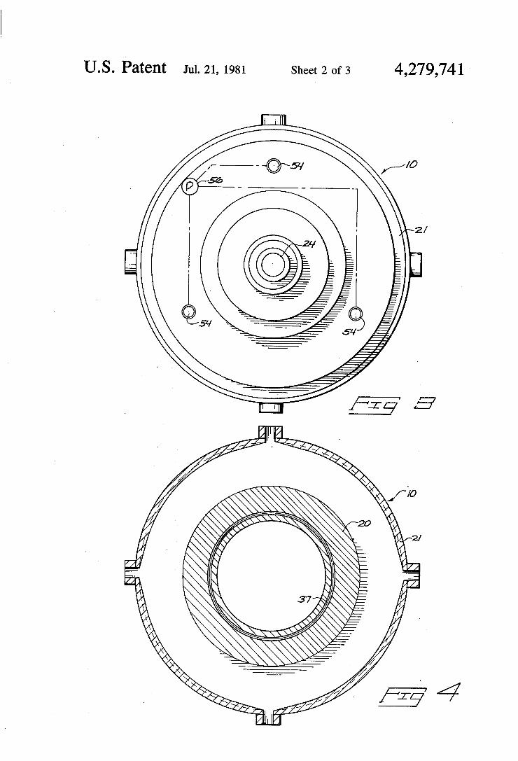
of the jig bed of the FIG. 1 embodiment during opera tion; FIG. 3 is a slightly reduced plan view of the jig as
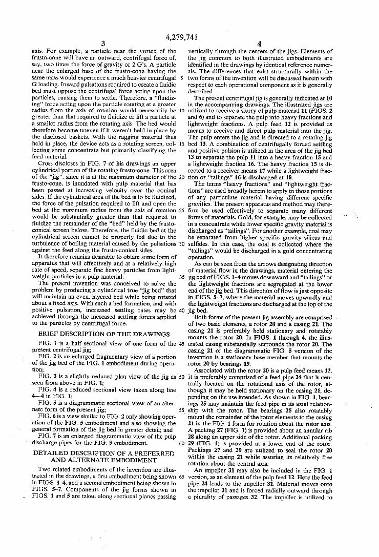
seen from above in FIG. 1; FIG. 4 is a reduced sectional view taken along line
4—-4 in FIG. 1; FIG. 5 is a diagrammatic sectional view of an alter
nate form of the present jig; - FIG. 6 is a view similar to FIG. 2 only showing oper
ation of the FIG. 5 embodiment and also showing the general formation of the jig bed in greater detail; and FIG. 7 is an enlarged diagrammatic view of the pulp
discharge pipes for the FIG. 5 embodiment.
DETAILED DESCRIPTION OF A PREFERRED AND ALTERNATE EMBODIMENT
Two related embodiments of the invention are illus trated in the drawings, a ?rst embodiment being shown in FIGS. 1-4, and a second embodiment being shown in FIGS. 5-7. Components of the jig forms shown in FIGS. 1 and 5 are taken along sectional planes passing
35
40
45
60
4 vertically through the centers of the jigs. Elements of the jig common to both illustrated embodiments are identi?ed in the drawings by identical reference numer als. The differences that exist structurally within the two forms of the invention will be discussed herein with respect to each operational component as it is generally described. The present centrifugal jig is generally indicated at 10
in the accompanying drawings. The illustrated jigs are utilized to receive a slurry of pulp material 11 (FIGS. 2 and 6) and to separate the pulp into heavy fractions and lightweight fractions. A pulp feed 12 is provided as means to receiveand direct pulp material into the jig. The pulp enters the jig and is directed to a rotating jig bed 13. A combination of centrifugally forced settling and positive pulsion is utilized in the area of the jig bed 13 to separate the pulp 11 into a heavy fraction 15 and a lightweight fraction 16. The heavy fraction 15 is di rected to a receiver means 17 while a lightweight frac tion or “tailings” 16 is discharged at 18. The terms “heavy fractions” and “lightweight frac
tions” are used broadly herein to apply to those portions of any particulate material having different speci?c gravities. The present apparatus and method may there fore be used effectively to separate many different forms of materials. Gold, for example, may be collected in a concentrate while lower speci?c gravity material is discharged as “tailings”. For another example, coal may be separated from higher speci?c gravity silicas and sul?des. In this case, the coal is collected where the “tailings” would be discharged in a gold concentrating operation. As can be seen from the arrows designating direction
of material flow in the drawings, material entering the jig bed of FIGS. 1-4 moves downward and “tailings” or the lightweight fractions are segregated at the lower end of the jig bed. This direction‘ of flow is just opposite in FIGS. 5-7, where the material moves upwardly and the lightweight fractions are discharged at the top of the jig bed.
Both forms of the present jig assembly are comprised of two basic elements, a rotor 20 and a casing 21. The casing 21 is preferably held stationary and rotatably mounts the rotor 20. In FIGS. 1 through 4, the illus trated casing substantially surrounds the rotor 20. The casing 21 of the diagrammatic FIG. 5 version of the invention is a stationary base member that mounts the rotor 20 by bearings 19.
Associated with the rotor 20 is a pulp feed means 12. It is preferably comprised of a feed pipe 24 that is cen trally located on the rotational axis of the rotor, al though it may be held stationary on the casing 21, de pending on the use intended. As shown in FIG. 1, bear ings 25 may maintain the feed pipe in its axial relation ship with the rotor. The bearings 25 also rotatably mount the remainder of the’ rotor elements to the casing 21 in the FIG. 1 form for rotation about the rotor axis. ‘ A packing 27 (FIG. 1) is provided about an annular rib 28 along an upper side of the rotor. Additional packing 29 (FIG. 1) is provided at a lower end of the rotor. Packings 27 and 29 are utilized to seal the rotor 20 within the casing 21 while assuring its relatively free rotation about the central axis. An impeller 31 may also be included in the FIG. 1
version, as an element of the pulp feed 12. Here the feed pipe 24 leads to the impeller 31. Material moves onto the impeller 31 and is forced radially outward through a plurality of passages 32. The impeller is utilized to

5 evenly distribute the pulp material about the rotational axis. A relatively uniform annular layer of pulp material can therefore be received by the jig bed 13. The FIG. 5 embodiment does not make use‘ of an
impeller. Instead, it includes a'number of radially ex tending delivery pipe sections 24a that extend from the central feed pipe 24. These pipes 24a are curved at their outward ends in the direction of rotation for the rotor in order to distribute the pulp material tangentially onto a substantially cylindrical batterboard 34. The batterboard 34 is common to both forms of my
jig and is included as a portion of the pulp feed 12. Batterboard 34 is situated adjacent the impeller 31 in the FIG. 1 version and closely adjacent to the outward curved ends of the pipes 24a in the FIG. 5 version. Pulp dischargedfrom the tubes or impeller is received by the annular batterboard 34 which is centered on the rota tional axis of the rotor. Batterboard 34 is also integral with the rotor 20. The batterboard 34 leads to an annular edge 35 of the
jig bed 13. This edge is de?ned by a wall of the jig bed that is substantially perpendicular to the rotor axis. The jig bed has a base at 36 that is de?ned by a cylindrical screen 37 (FIGS. 2 and 6) centered on the rotational axis of the rotor 20. The screen 37 is designed to receive and support “ragging” which may be metallic spheres 38 or appropriate particulate materials such as hematite, which are commonly used for such purposes. The cylin drical screen 37 holds the ragging against outward movement as the rotor is spun about its axis. The screen'37‘ may be provided in the form of three
separate overlapping cylindrical sections preferably woven of wire mesh. The two outer screen sections may be formed of a relatively heavy, wide mesh screen ing material. The center section sandwiched between the outer sections can be considerably lighter in weight and of a selected mesh size. For example, it may be preferable to use a mesh size smaller than 100 mesh for gold concentrates. The two outer screens would then serve as reinforcements to support and protect the more delicate inner screemOther screen sizes and styles may be utilized, depending on the ore to be concentrated and the nature of the pulp. The screen 37 is upright and leads axially from the
surface de?ning edge 35 to a horizontal surface. This surface de?nes a jig bed edge 41 in FIG. 1. In the FIG. 5 embodiment, the edges 41 and 35 are reversed in posi tion due to the reverse operational flow of material through the jig. In either embodiment, however, the edge 41 may extend radially outward beyond the screen 37 into the receiver means 17.
It is preferred that the two edges 35 and 41 be sub stantially radially spaced from the central rotating axis of the rotor by equal distances. However, the distances may be varied to have a corresponding effect on the operational depth of the resulting jig bed, so long as the jig bed itself across screen 37 remains cylindrical.
The‘ lightweight fraction leaves the jig bed 13 through operation of a discharge means that includes ‘the edge 41. The light fractions will move over edge 41 to be receive'd'by an annular discharge wall 43 of the FIG. 1 embodiment. The wall 43 is centered on the rotational axis of rotor 20 and is preferably upright. The wall 43 may be slightly flared downwardly to encour age increased ?ow rate of the lightweight fraction or “tailings” from the rotor. A receiving tank 44 is sup plied directly below the open end of wall 43 for receiv
4,279,741
10
6 ing the lightweight fraction. Tank 44 will collect the lightweight fraction for further handling or disposal.
In the FIG. 5 embodiment, no upright discharge wall is illustrated. Instead, the tailings merely move over the edge 41 to be collected at a position radially adjacent to the edge. The tailings of both forms may be collected, processed, and recirculated through the jig as necessary to assure complete practical concentration of the se lected material. The FIG. 1 version of casing 21 forms the receiver
means 17 and is held stationary relative to the rotating jig bed. In the FIG. 5 version, however, an integral portion of the rotor forms the receiver means 17, rotat ing with the jig bed about the central axis. _ The receiver means of the FIG. 1 version is de?ned
by an upper casing plate 50 that is joined by an upright peripheral casing wall 51 to a lower casing plate 52. The receiver means enclosed within the casing 21 is thus annular and extends radially outward of the jig bed 13. It maintains an open ?uid communication with the inte rior of the jig bed for receiving ?uid and heavy frac tions during rotation of the rotor. Along the lower plate 52 are a plurality of discharge ori?ces 53. The “hutch
' product” or ?uid and heavy fractions are discharged 25
35
40
45
50
60
65
through the ori?ces 53 to an appropriate concentrate collecting device such as a tank or other appropriate container (not shown). The FIG. 5 version of the receiver means 17 rotates
with the rotor. Here the receiver means 17 is de?ned by horizontal rotor walls 500 and 52a and a radially out ward converging collector wall 510. Rotation of the receiver means 17 with the jig eliminates turbulence within the area radially outward of the jig bed and facilitates collection of the concentrate through centrif ugal force acting upon the concentrate to move it radi ally outward through ori?ces 53a and the converging Walls 51. The concentrate may be delivered through the rotating periphery of the rotor to an annular collection housing 53b. The housing 53b as shown in FIG. 5 may be mounted adjacent to the rotor and held stationary by the casing 21. Appropriate vanes 530 may be provided on the exterior surfaces of the rotor adjacent the ori?ces 53a for creating cavitation within the collector housing 53b in order to prevent radial inward escape of fluid and concentrate from the joint between the housing and the rotor. >
The annular area de?ning the receiver means 17 within the'casing of the FIG. 1 embodiment is open to contain slurry of “hutch” ?uid in communication with the jig bed. The hutch ?uid is preferably directed into the receiver means 17 through two or more equally spaced apertures 54. The apertures 54 are formed through the upper plate 50 but may be provided else where along the casing. Apertures 54 are connected to a valved pump 56 for pumping the ?uid under pressure. The pumped ?uid ?lls the entire annular receiver area or hutch and maintains ?uidic communication with the jig bed 13. This area is also where heavy fractions (con centrate) are received and directed toward the ori?ce 53. .
In the FIG. 1 embodiment the ?uid is pumped into the casing in pulsations formed by the valved pump 56’. The ?uid is thus pulsed radially inward to intermittently produce a ?uidic bed inwardly adjacent the rotating screen 37, through which the heavy fractions may settle by the known “hindered settling” process. The settling process is substantially accelerated, how
ever, by centrifugal force acting against the “heavys” or
7 high speci?c gravity particles due to the rotating jig bed. At the termination of each pulsationnthe' ragging and
pulp within the jig bed are allowed to settle radially outward against the screen 37. Alternate positive pulsa tions will therefore serve to eventually “jig” the light weight fractions over edge 41 along with a portion of the “hutch” ?uid carrying the pulp while the heavy fraction remains within the jig bed and settles through the screen into receiver means 17. The centrifugal forces, being much greater than the force of gravity, cause even extremely ?ne particles of heavy fractions to settle through the ragging and screen 37. The heavy fractions then migrate radially outward due to centrifu gal force, to be collected adjacent the discharge ori?ces 53.
It is noted that the pulse produced in the FIG. 1 embodiment is supplied through the valved pump 56. Alternatively, the pulse produced by the FIG. 5 em bodiment is supplied through an integral pulsator 60 that ?ts within the rotor itself. The pulsator 60 includes an upright hollow shaft 61
for receiving fluid from a pressurized source such as a standard commercial water pump. It is preferred that the fluid be delivered under constant pressure to the pulsator 60. The shaft 61 leads upwardly to a pulsator head 62.
The head 62 is hollow and openly communicates with the interior of the shaft 61. The pulsator head includes a peripheral inclined pulsator wall 63 that is centered on the central rotor axis and includes a frusto-conical con ?guration. Preferably two opposed openings 64 are formed through the walls. The rotor receives the pulsator head 62 within a
complementary recess that includes a peripheral rotor wall 70 spaced slightly outwardly of the peripheral pulsator head wall 63 and includes opposed openings 71 formed therethrough. The openings 71 are movable with the rotor in circular paths the intersect the open ings 64. As the rotor spins about its central axis, the openings 71 will therefore periodically come into open communication with the pulsator head openings 64. The pressurized ?uid will be allowed to ?ow in succes sive pulsations through the aligned openings and into the hutch area. The ?uid pulsations are then carried through the ?uid to the jig bed where they function to intermittently create a ?uidic bed of the pulp material. The pulsator head is held stationary by the casing 21
but is adjustable vertically by a bypass means that in cludes an adjusting nut 69 situated at an outward end of the shaft. The nut 69 threadably engages the shaft and the casing 21 in order to axially adjust the position of the pulsator head in relation to the adjacent components of the rotor. The purpose of the bypass means in providing axial
adjustment of the pulsator head is to control seepage from the pulsator head directly into the receiver means 17. The wall surfaces of the pulsator head and rotor wall will normally substantially nest together and there fore very little seepage will be allowed from opening 70 into the hutch area. However, if the adjusting nut is turned to move the shaft and the .af?xed pulsator head axially with respect to the rotor wall, the gap between rotor wall 70 and pulsator wall 63 will increase and additional ?uid will be allowed to enter the hutch and jig bed. The steady seepage applies a continuous posi tive pressure to the ?uid within the hutch and yet al
4,279,741
25
55
65
8 lows the positive pulsations to elevate the pressure in termittently to pulsate the jig bed.
Selective adjustment of seepage volume or rate may be used when the present jig is to be utilized to separate different ores. It is also noted that the pulse produced through either the pump 56 or the pulsator head can be varied in duration, pressure, and frequency, depending upon the type of ore, the ?ow rate of the pulp, and the rotational velocity of the rotor.
It has been found through experimentation that the rotor velocity ‘must be maintained at a rate suf?cient to produce a corresponding outward centrifugal force at the screen of at least ten times that of gravity. If the ratio of centrifugal force to gravitational force does not equal at least ten to one, the resultant angle of repose of the jig bed on the cylindrical screen may become such that boiling will occur. At forces above 10 G’s, the angle of repose gradually approaches an angle perpen dicular to the radial lines of force generated from the central rotational axis. The jig bed will therefore be come substantially cylindrical (as shown by FIG. 6) and retain a uniform radial depth from top to bottom during rotation imparting 10 G loading.
Both the ragging and pulp or feed materials are loosely held by the screen ‘and will naturally drop downwardly out of the jig bed when the rotor is stopped. For this reason ?ow of ?uid is stopped and the rotor is run dry for a period before rotation is stopped. The dried pulp and ragging will then adhere to the screen and stay in place. The present method may now be easily understood in
terms of operation of the above described apparatus. ‘Prior to initiating operation of the present jig, the
rotor is powered by an appropriate drive mechanism 80 (FIG. 5) to rotate about its axis. Preferably, the rotor is driven to rotate about its center axis at a velocity suf? cient to bring the ragging against the screen with a force of ten times that of gravity (1O G’s) or higher. The ?uid supply mechanism may then be‘ac'tuated to start pulsa tions through the screen. A supply of pulp material is directed to the feed pipe 24, by a conventional mecha nism (not shown) selected to deliver the pulp material in a slurry at a rate compatible to the operating rate and size of the jig.
In the FIG. 1 embodiment the pulp slurry will move downwardly and be received by the impeller 31. Mate rial striking the impeller will be guided radially outward through the passages 32 to the batterboard 34. Since the batterboard and impeller rotate simultaneously, there is only a slight shearing effect produced between the r0 tating board and the outwardly moving pulp. The pulp will therefore almost immediately rotate in unison with the batterboard. The rotational rate of the rotor will be such that the
pulp material will be held against the batterboard by >_ centrifugal force. Gravity and reception of additional material along the batterboard act to cause the previ ously received material to move downwardly and over the upper edge 35 of jig bed 13. As indicated above, the step of rotating the jig bed (since it is physically integral with the rotor) is accomplished as the rotor is actuated.
In the FIG. 5 embodiment, the slurry of pulp is deliv ered through the radial tubes 24a directly to the batter board. The incoming slurry displaces previously deliv ered slurry and thus forces it upwardly along the batter board to the jig bed and eventually out over the dis charge edge at 41.

9 It should be noted that either embodiment may be
inverted or turned at ‘substantially any'angle. The jig will still function ef?ciently‘. "Therefore, it’ is irrelevant whether the pulp material enters below or above the jig bed. The pulp can‘ be made'to“ flow both axially and radially when delivered; from above o'r‘below. ' - > The step of “jigging’f the pulp ,within the jig bed-‘is
accomplished by producing ?uid ?ow in a, series of ?uid pulsations directed radially inward through ‘the jig bed. The duration, frequency, and pressure of the pulsations
4,279,741
may be variable depending upon the _ore intended for ‘ collection. Radial inward movement of the ?uid will suspend the pulp material in a ?uidic bed. . The heavy fractions settle through the ragging and
against or through thescreen upon termination of each pulsation. As the positive pulsation‘terminate's, centrifu gal force quickly overcomes the radial inward force of the pulsation andcauses more rapid outward movement of the heavy fractions toward the screen than the same movement of the lightweight fractions. The lightweight fractions or lower speci?c gravity particles will remain at a level withinmthe ji'g bed and} eventually will move gradually toward the discharge edge 41. After several successive pulsations, the lower speci?c .gravity mate rial will have worked its way over the discharge edge 41 and will proceed toward discharge and reception within the receiving tank‘ 44 (in ‘the FIG. l'form). Flow of the lightweight fractions is assisted by steady inward ?ow of the pulsating ?uid, some‘ of which escapes through the jig bed' and is discharged with the tailings.
Collecting the: heavy‘v fraction is accomplished by providing outlet ori?ces 53, 53a radially outward of the jig bed. The heavy ‘ fraction‘ is received through the screen and moves through the hutch area radially out ward to migrate through the discharge ori?ces 53, 53a. Middlings, if ‘any are produced, are retained within the tagging and against the screen. ' ‘
In the FIG. 5 embodiment the pulsations of the'?uid are produced through rotation of the rotor as the wall openings 71 move in their circular paths to periodically communicate with the openings 64 in the ‘ stationary pulsator head. Fluid delivered through the pulsator head under constant'pressure will thus be delivered to the jig bed in positive‘pulsations in response to rotation of the rotor. The present method utilized in conjunction with ei
ther embodiment may also include the step of allowing a select amount of seepage to the jig bed. This may be done, for example, by the adjusting nut and thread ad justment of the bypass means on the pulsator shaft de scribed above in the FIG. 5 embodiment. It may also be done by allowing seepage through the valved pump 56 _of the FIG. 1 form.
The pulating ?uid carries the tailings over the edge 41 of the jig bed. The tailings and expelled ?uid will
5
40
45
readily flow into an associated receptacle. This proce- I dure comprises the ?nal step of discharging the light weight fraction. '
It is to be noted that the present method is continuous and that the steps described above occur simulta neously. Pulp is fed into the apparatus while pulp is being segregated on the jig bed. The pulp material is continuously separated into heavy fractions and light weight fractions with the heavy fractions being dis charged through the ori?ces 53 as the lightweight frac tions are being discharged over edge 41. The above description and attached drawings are
given merely by way of example to set forth a preferred
60
0.
10 and alternate form of the present invention and appara tus.‘ The following claims are given‘to more restrict the scope of the present invention. What I claim is:
' 1. A centrifugal jig for separating atheavy fraction from a lightweight fraction of a pulp material, compris ing: ‘
a a casing; a hollow rotor mounted to the casing about a rotor
axis; a cylindrical jig screen mounted coaxially to the rotor
’ for rotation therewith about the rotor axis for re ceiving pulp material to form a cylindrical jig bed;
‘ means for rotating the rotor and cylindrical jig screen about the rotor axis at suf?cient velocity to cause centrifugal loading on the cylindrical jig screen at least equal ‘to ten times the force of gravity;
feed means for directing pulp material onto the cylin drical jig screen;
means for simultaneously directing positive ?uid pul sations radially inward through the total circumfer ence of the jig screen to form a uniform layered cylindrical pulsating ?uidic bed of the pulp mate rial on the cylindrical jig screen as it is rotated about the rotor axis;
discharge means adjacent the cylindrical jig screen adapted to receive a lightweight fraction of the pulp material; and
receiver means in communication with the exterior of the jig screen for receiving ?uid and the heavy fraction of the pulp material from the jig screen during rotation of the rotor means.
2. The centrifugal jig as de?ned by claim 1 wherein the pulp feed means includes a pulp delivery pipe lead ing into the rotor for directing pulp radially toward the jig bed.
3. The jig as de?ned by claim 1 wherein the receiver means is formed within the casing and extends annularly about the rotor means.
‘ 4. The jig as de?ned by claim 1 wherein the receiver means extends annularly about the rotor and rotates with the rotor.
5. The jig as de?ned by claim 1 wherein the pulp feed means includes a pulp delivery pipe leading into the rotor and wherein the pulp delivery pipe is coaxial with the rotor axis.
6. The jig as de?ned by claim 1 wherein the cylindri cal jig screen is positioned within an inwardly facing annular recess formed in the rotor.
7. The jig as de?ned by claim 1 wherein the means for directing ?uid pulsations further comprises pulsator means operatively connected to the rotor for receiving ?uid under constant positive pressure and for supplying pulsations of the pressurized ?uid through the jig screen in response to rotation of the rotor.
8. The jig as de?ned by claim 7 wherein the pulsation producing means includes ?uid bypass means for allow ing a constant seepage of pressurized ?uid from the pulsation producing means and through the cylindrical ‘ jig screen;
and adjusting means for selectively varying the rate of seepage ?ow.
9. A method for separating a heavy fraction from a lightweight fraction contained in a pulp material, com prising the steps of:
(a) placing the slurry of pulp material in a cylindrical jig bed;

4,279,741 11
(b) rotating the cylindrical jig bed about its central axis at sufficient velocity to cause centrifugal load ing on the cylindrical jig bed at least equal to ten times the force of gravity so as to force the slurry of pulp material radially outward by centrifugal force;
(0) simultaneously jigging the pulp material within the rotating cylindrical jig bed by positively pul sing a ?uid radially inward simultaneously through the total circumference of the rotating cylindrical jig bed to form a uniform, layered cylindrical pul sating ?uidic bed through which the heavy fraction will settle radially outward and the lightweight fraction will migrate toward a discharge;
(d) collecting the heavy fraction; and (e) separately discharging the lightweight fraction. 10. The method as set out by claim 9 wherein the step
of placing the pulp into the cylindrical jig bed is accom plished by:
(a) moving the pulp material axially to an elevation adjacent the jig bed;
(b) moving the pulp material at said elevation radially outward to a rotating annular batterboard; and
(0) moving the slurry of pulp material axially from the rotating batterboard to the rotating jig bed.
11. The method as set out by claim 9 wherein the steps of jigging the pulp and collecting the heavy frac tions therefrom are accomplished by:
(a) providing a cylindrical screen at a base of the jig bed;
(b) providing ragging along the base radially inward of the cylindrical screen to form interstices through which the heavy fraction may settle; and
(c) directing the ?uid pulsations radially inward through the screen and interstices of the ragging to ?uidize the jig bed and allow settling of the heavy fraction through the ragging interstices as assisted by centrifugal force produced through the rotating cylindrical jig bed.
12. The method as set out by claim 9 wherein the step of rotating the jig bed is accomplished about an upright rotational axis.
13. The method as set out by claim 12 wherein the step of jigging the pulp material within the rotating jig
15
25
30
35
45
55
65
12 bed is accomplished by directing a fluid around the exterior of the jig bed and pulsing the ?uid radially inward through the jig bed.
14. The method‘ as set out by claim 9 wherein the step of collecting the heavy fraction is accomplished by providing annular hutch means in ?uid communication with the exterior of the cylindrical jig bed for receiving the heavy fraction during rotation of the jig bed.
15. The method as set out by claim 14 wherein the step of collecting the heavy fraction further comprises the step of rotating the last annular hutch means with the jig bed. ‘ -
16. The method as set out by claim 9 wherein the steps of placing the pulp material into the cylindrical jig bed, rotating the jig bed, and jigging the pulp material are all performed simultaneously.
17. The method as set out by claim 9 wherein the step of rotating the jig bed is accomplished about an upright rotational axis.
18. The method as set out by claim 9 wherein the step of jigging the pulp material is accomplished by:
(a) journalling a pulsator head within the rotor with an annular pulsator wall centered on the rotor axis;
(b) delivering a ?uid under constant pressure to the pulsator head;
(0) positionin'gian annular rotor wall within the rotor adjacent the pulsator head;
(cl) holding the pulsator head against rotation about the rotor axis relative to the rotor wall;
(e) moving an opening through the annular rotor wall - in circular paths past a similar opening in the annu lar pulsator wall intersecting the opening in the rotor wall so ?uid delivered to the pulsator head under constant pressure will be delivered to the jig bed in positive pulsations in response to rotation of the rotor. I
19. The method as set out by claim 18 comprising the further step of allowing seepage of the ?uidv from the pulsator head to the jig bed.
20. The method as set out by claim 19 comprising the further step of selectively controlling the rate of seep age of fluid from the pulsator head.
‘ i it i *