method and apparatus for detecting optical defects in transparent
TRANSCRIPT

United States Patent 1191 [11] 3,989,387 Hategan [45] Nov. 2, 1976
[54] METHOD AND APPARATUS FOR 3,667,846 6/1972 Nater et a1 ........................ .. 356/120 DETECTING OPTICAL DEFECTS IN TRANSPARENT SHEETS Primary Examiner-John K. Corbin
_ Assistant Examiner-Matthew W. Koren [75] Inventor’ 21:32:” Hategan’ Charenton’ Attorney, Agent, or Firm-Pennie & Edmonds
[73] Assignee: Saint-Gobain Industries, Neuilly-sur-Seine, France [57] ABSTRACT
- _ Apparatus for detecting and measuring imperfections [2,2] Flled' Dec’ 11’ 1974 such as wedge, combing and lack of planarity in trans [21] Appl. No.: 531,610 parent sheets such as glass comprises an extended lu
. . minous source, focusing means to form a convergent . Relf‘te‘i U's' Apphcamn Data beam containing an image of the source, a differential
[63] Cmtmuammmpa" °f Se‘ N°' 290'528’ Sept 20’ photoelectric cell positioned to receive that image 1972’ abandoned‘ after passage of that beam through, or re?ection
. . . . . thereof at, the sheet, and circuit means connected [30] Forelgn Application Pnonty Data with the cell for producing a changed output upon
Sept. 24, 1971 France ............................ .. 71.34556 of the image on the cell due to changed fefl-ac
tion or re?ection of the beam at the sheet produced [52] US. Cl. .............................. .. 356/239; 250/562; by a defect The beam of focused light is limited or
2 250/572; 356/200 stopped so that a cross-sectional dimension thereof is [5 III‘. Cl. ........................................ .. of the Same order of magnitude as the of typical [53] Field M Search --------- -- 356/120’ 199’ 200’ 201’ defects in the sheets. According to the method of the
356/209, 237, 239; 250/572, 562, 56-3 invention the sheet is advanced in its own plane rela _ tively to the source, focusing means, cell and stop, in
[56] References Clted a direction parallel to the width dimension of the de UNITED STATES PATENTS fects in the sheet, this direction of motion being paral
3,199,401 8/1965 Sleighter et al ................... .. 356/200 lel t0 the Said cross-sectional dimension of the beam, 3,338,130 8/1967 Gaffard ..................... .. 250/572 X . _ .
3,639,112 2/1972 Poola ......................... .. 356/120 x 13 Claims, 11 Drawmg Flgures

US. Patent‘ Nov. 2, 1976 Sheet 1 of5 3,989,387


US. Patent- Nov. 2; 1976 Sheet 3 of5 3,989,387
6| 4 56 53b
_ , 50
Y” ‘W/ =~ ~ 52%: {I ‘TX 7 5| % 53 7
FIG. 9 54
‘HM, Tm“

Sheet4 of 5 3,989,387 US. atent Nov. 2, 1976
U.S. Patent Nov. 2, 1976 Sheet 5 of5 3,989,387

3,989,387 1
METHOD AND APPARATUS FOR DETECTING OPTICAL DEFECTS IN TRANSPARENT SHEETS This application is a continuation-in-part of my appli
cation Ser. No. 290,528, ?led Sept. 20, 1972, now abandoned. The present invention has for its chief purpose the‘
provision of apparatus and method for detecting and measuring variations in the optical characteristics and properties of a body of regular geometrical form such as a sheet of glass of nominally uniform thickness. The invention can be used for example to measure the an gles of prisms or variations in the refractive index of a thin plate of transparent material having parallel oppo site surfaces, for detecting and measuring optical de fects which may exist in a sheet of glass, and for mea suring its light transmitting properties. An important object is to provide a method and ap
paratus which enable the determination and correction of imperfections in sheet glass during its manufacture. A large percentage of sheet glass of high quality is, at the present time, produced by procedures consisting in melting raw batch ingredients in a furnace, followed by vertically drawing upwardly from the surface of the bath of molten glass in the furnace, or by drawing the incipient molten glass sheet horizontally over and ?oat ing it upon a bath of molten metal such as tin. The main optical defects usually encountered in sheets so manu factured are elongated in the direction in which the glass was drawn, this is in the direction of the draw whether that be vertical of horizontal, as aforesaid. In general the defects are the result of:
a. Local heterogeneities of composition in the glass and, consequently, variations in its index of refraction from one area to the next;
b. Combing, a defect resulting from localized differ ences in temperature or viscosity and which form min- ute striations and like effects;
c. Distortion, a defect similar to combing but of greater intensity, value and importance;
d. Undulations in the surfaces of the glass and which are of yet more importance. Defects such as those above named effect small mag
ni?cations and when straight and narrow may be lik ened to cylindrical lenses of variable powers. The power, and hence the intensity of each defect, may be expressed as a derivative or function of the deviation of a ray of light traversing the glass in a direction perpen dicular to the ?aw, that is, the deviation with respect to that observed in an essentially perfect specimen.
In the prior art, various attempts have been made by empirical or semi-empirical procedures to determine defects in sheet glass by observing changes in the index of refraction or the planarity, by observing deviations of rays of light incident on or traversing the specimen. However, the accuracy of such observations is ham~ pered by diffraction effects so that the degree of preci sion attainable is not suf?cient, particularly in the case of small or minute defects or ?aws in structure.
In accordance with the present invention, the article to be tested is scanned with light coming from an ex tended luminous source or object which has passed through an image-forming objective lens in the vicinity of the article and which is on its way to the formation of a real image of that object. The light from the source may have been stopped down by a diaphragm whose opening has a small dimension parallel to the direction of scan, this diaphragm being in the vicinity of the
15
25
35
40
45
50
55
60
65
second principal plane of the objective lens. The ex tended luminous source lies in a plane parallel to the diaphragm and possesses a similar slitlike shape, of dimensions preferably at least twice those of the dia phragm. _
The rays thus incident on and traversing, or re?ected at the article under test, are incident upon a differential photoelectric cell located in the plane of the image of the luminous object formed by the objective lens. The cell supplies an output signal which varies with the displacements, even minute, of the image which are produced by irregularities in the article under test. In the examination for example of ?at glass, the invention is capable of operating with the luminous object and photocell on opposite sides of the‘ glass sheet under test, and with the light passing either essentially nor mally or obliquely through the sheet. The invention also includes, however, examination of such flat glass with luminous source object and the photocell on the same side of the glass sheet by re?ection either at the near surface or at the far surface of the glass, in the latter case with two traverses through the glass, or, alternatively, upoon re?ection of the light from a mir ror spaced from the test sheet. Thus, where it is desired to detect flaws or blemishes
in a sheet or ribbon of glass being drawn, the optical apparatus may be advantageously oriented so that the longitudinal axes of the luminous source and the slit of the stop are parallel to the direction of the draw. The sweep of the scanning rays will be perpendicular to the direction of the draw and may be effected by move-' ment of the optical apparatus relatively to the sheet, or vice versa. The signal of the photoelectric cell output circuitry can be used directly, or following treatment in one or several ways. In a generally advantageous proce dure, the signal is utilized after high and/or low pass ?ltering, differentiation, recti?cation and recording. Themethod may be carried out by apparatus subse
quently described, it being understood that the means shown and described is set forth in a purely illustrative rather than a limiting sense.
BRIEF DESCRIPTION OF THE DRAWING
FIG. 1 shows schematically one form of apparatus according to the invention; FIG. 2 is a fragmentary view of the source — de?ning
means and beam stop in the apparatus of FIG. 1; FIG. 3 is a detail view of the photoelectric cell of
FIG. 1 shown rotated through 90°; FIG. 4 is similar to FIG. 1 but showing a modi?ed
form of apparatus in accordance with the invention wherein there are two traverses of the sheet by the scanning beam, with an intermediate re?ection by a mirror; FIG. 5 shows another form of apparatus in accor
dance with the invention, also similar to FIG. 1, but in which there occurs one re?ection from the upper or adjacent surface of the glass or, alternatively, a re?ec tion of the beam from the lower or remote surface of the sheet with an intermediate two traverses or the sheet; - 7
FIG. 4 is a block diagram showing the circuitry by which the signal detected by the cell of FIG. 1 is treated; ’
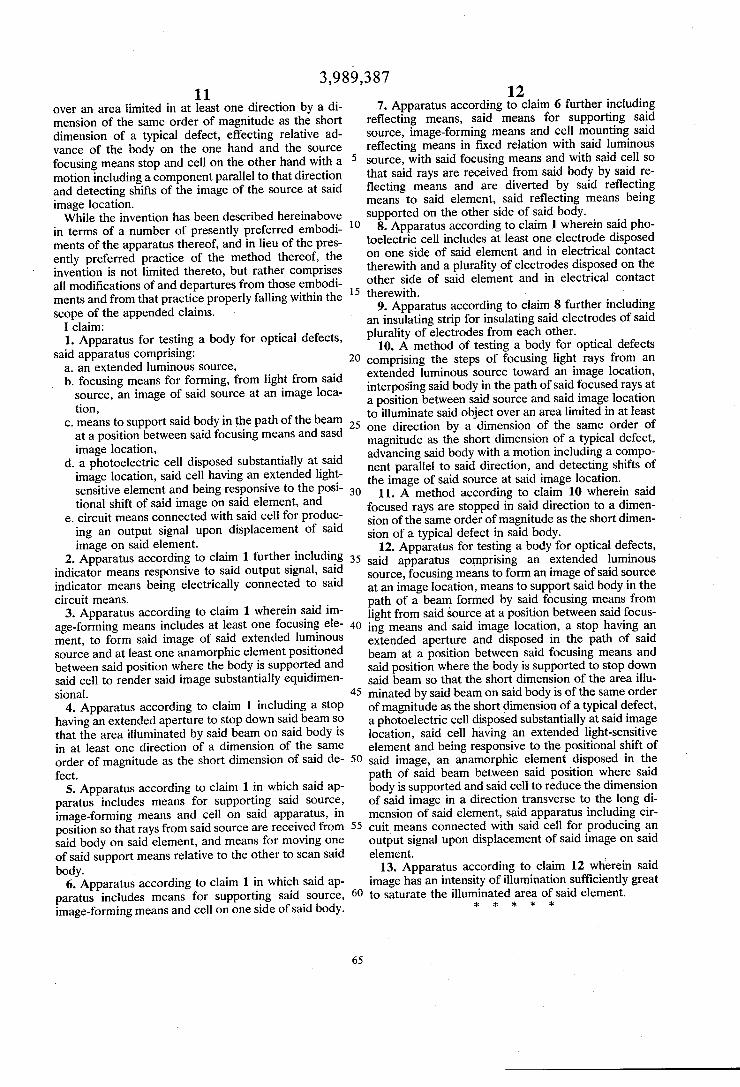
FIGS. 7, 8 and 9 are views in plan, front elevation and side elevation respectively, showing means for mount ing an apparatus according to the invention and capa

3,989,387 3
ble of use in scanning and testing, over its entire area, a sheet of glass supported on those means; FIG. 10 is a vertical sectional view to an enlarged
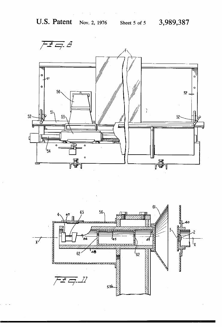
scale, through the central or principal optical axis thereof, of that portion of the apparatus of FIG. 9 dis posed, as seen in FIG. 9, at the right of the sheet to be scanned; and FIG. 11 is a vertical sectional view corresponding to
FIG. 10 but showing that portion of the optical appara tus disposed at the left of the sheet, as viewed in FIG. 9.
DESCRIPTION OF THE PREFERRED EMBODIMENTS
Referring to FIG; 1 which for clarity of illustration is not drawn to scale, reference character 1 denotes an opening in a diaphragm 1 ’, the opening being uniformly illuminated from a source such as a lamp 57 with the help of a condenser lens 58. Reference character 1 thus denotes an extended luminous source, which consti tutes the object of which an image is produced by the lens 2 to be mentioned presently. The source is desir ably of rectangular shape, and may have two long sides A and B and two short sides C and D, these being the sides of the opening in the diaphragm 1'. To the right of the source is disposed an image-form
ing means such as a lens, indicated at 2, which forms, from light emerging from the diaphragm l’, a conver gent beam containing a real image of the source 1. This beam, after passage through a sheet F undergoing test and through an anamorphic lens 63, comes to a focus in an image plane occupied by a differential photocell 4 and there forms a real image of the source 1. Assuming the sheet F to be, in the region thereof instantaneously explored by the beam, a plane parallel plate without defect, the image will have a shape such as that indi cated by the rectangle of crosses identi?ed by refer ence character 16. The image is reduced in height along the Z—Z axis shown in the ?gure by the power, in the meridian of that axis, possessed by the lens 63. Of course, the greater power in that meridian, which con tains the system axis X—X and the axis Z—Z above referred to, will mean a shorter focus for the system in that meridian than in the perpendicular meridian con taining the system axis X—X and the transverse axis Y—Y at the image plane of cell 4. Since however, the instrument is not a visual one, this split in foci is unim portant. Assuming the plate F to have a defect in the portion thereof traversed by the beam, the image will be displaced to a position such as that indicated by the rectangle 16’ of small circles.
If the defect, like the defect 18 shown, is a defect such as a striation extending substantially parallel to the axis Z—Z, which is the direction in which the glass has been drawn (identified by the arrow d in FIG. 1), the image shift will be along the axis Y—Y. The photo cell 4 and associated equipment signal this shift in the image, which occurs as the sheet F is moved relatively to the other elements in the direction h parallel to the axis Y—Y when the defect 18 reaches the location 17 where the beam carrying the image of source 1 passes through the sheet F. A second diaphragm or stop 3’ having an aperture 3
is desirably located parallel to and adjacent the objec tive lens 2. The effect of diaphragm 3 is to stop down, at the axial location of the sheet F, to the dimensions of the rectangle 17, the cross~section of the convergent beam formed by lens 2 from light diverging from the extended luminous object 1. As is seen in FIG. 2, the
5
40
45
55
65
apertures 1 and 3 are in parallel plans, are of rectangu lar form, and have their longitudinal and transverse dimensions respectively parallel. The width of aperture 1 is several times, at least twice, the width of aperture 3. The width, that is the short dimension, of aperture 3, is chosen so that the width of the area 17 illuminated by the beam incident on the article under test is preferably less than one third the width or half period of an elon gated defect, indicated at 18, usually encountered in drawn glass. ' Thus the concentrated rays from the extended lumi nous source, constituted by aperture 1, are focused by objective lens 2 into a convergent beam and then stopped down by aperture 3 so as to illustrate a slit shaped area 17 on the sheet of glass F being tested parallel to the long dimension of defect 18. After pass ing through the sheet F, the beam traverses an anamor phic lens 63, to form an enlarged inverted real image, identi?ed at 16, upon a differential photoelectric cell generally indicated at 4 and further shown in FIG. 3. By operation of the anamorphic lens the long sides A’, and B’, of the image of source 1 formed by objective lens 2 are compressed to form an approximately equidimen sial or nearly square shaped image 16. While the ana morphic lens will produce a split in the foci of the optical system, this does not affect the operation of the invention. The photoelectric cell 4 is further shown in FIG. 3. It
includes a strip 5 of photoconductive material, an elec trode 6 contacting the strip 5 along one of the long sides of the striip, and two electrodes 7 and 7a each contacting the strip 5 along substantially one-half of its other long side. The electrodes 7 and 7a are separated from each other by a neutral strip 8 which may be formed either of photoconductive material or of insu lating material. The cell 4 is oriented with respect to the source 1 of FIGS. 1 and 2 so that the longitudinal axis Y—Y of the strip 5 in FIG. 3 is parallel to the short sides C and D of that source. Z—Z is an axis perpendic ular to axis Y—Y, and like axis Y—Y is in the plane of the image and hence in the plane of the surface of the strip 5, and passes through the neutral strip 8. The halves of the strip above and below axis Z—Z may be called 50 and 5b. The dash line rectangle 16 in FIG. 3, corresponding to the rectangle of crosses 16 in FIG. 1, denotes the rectangular image of the source 1 formed on the photocell by the objective lens 2 and anamor phic lense 63 when the test piece F is without ?aw in the portion thereof traversed by the light which makes up this image and which is passed by the stop 3'. In the event of a ?aw, the image is displaced to a position such as that indicated by the full line rectangle 16', corre sponding to the rectangle of small circles 16' of FIG. 1. The cell is desirably so positioned with respect to the source 1 and lens 2 that the undeviated image 16 in FIG. 3 extends equally above and below the axis Z——Z.
Referring to the circuit diagram of FIG. 6, voltage sources 22 and 23 are connected in series between electrodes 7 and 7a with the junction 21 of those sources being grounded. Resistors 25 and 24 are also connected in series between electrodes 7 and 7a with the junction 26 of those resistors being connected to the electrode 6. The voltage difference between points 21 and 26 is applied across an output impedance 27. The impedance 27 feeds a low pass ?lter 31 described below. ‘
In the absence of a test specimen, or when a speci men, although present, is essentially free from imper

3,989,387 fections over the small area thereof ‘traversed by the light rays from the source which are focused by lens 2 and passed by stop 3', the image 16 of slit 1 is central ized with respect to the axes Y_Y and ZZ of light sensi tive strip 5, and the output signal of terminals 26 and 21 is of a reference value. However, when a sheet F is in position as in FIG. 1
and has at the area 17 traversed by the light rays a defect such as for instance, a lack of 'true planarity or abnormal index of refraction, the image 16 is shifted, as shown exaggeratedly in FIG. 1, to a location 16' in the plane of the face of cell 4. As indicated in FIG. 3, when the image 16 shifts, as a
result of defect in sheet F, to a location 16’, the illumi nated area of half-strip 5a is decreased while the illumi nated area of half-strip 5b is increased. The change in the areas illuminated by the shift of the image results in a voltage between points 26 and 21, of the circuit shown in FIG. 6, which is difficult from the reference voltage present at these terminals when the image is at the location 16. The difference between the reference voltage produced by the shifted image is a function of the shift in the image and hence of the magnitude of the optical defect in the body being tested. The differential voltage thus resulting may be treated in a number of ways. FIG. 6 shows one such way wherein a low pass ?lter 31 and a high pass ?lter 32, or an equivalent band pass ?lter, and a differentiator 33, a recti?er 34, and a register, recorder or indicator 35 are serially connected in the order mentioned. The invention also makes pos sible direct utilization of the output signal from the terminals of resistance 27, to afford a graph of devia tions. When the signal is integrated, a graph can be prepared giving variations in thickness of the sheet or ribbon of glass. The parameters of the optical system are chosen so
that the width, C0 or Do in FIG. 3, of the image 16 is less than longitudinal dimension of strip 5, and the shifted image is at all times completely incident upon the strip 5 up to the maximum magnitude of the defect which the instrument is capable of detecting or sensing. Preferably the intensity of illumination of image 16 is
suf?ciently great so that the illuminated portions of the areas 5a and 5b operate at‘saturation. This has the double advantage that the sensitivity of the instrument is at a maximum, while at the same time, variations in output signals otherwise caused by accidental and un desired variations in the intensity of incident light, are avoided. Thus the instrument is made solely responsive to the difference in the illumination of the areas 5a and 5b. To obtain the desired sweep of the specimen, for
instance a sheet of drawn glass, the apparatus is ori ented so that the longitudinal axes of slits l and 3 and the axis Z-Z of cell 4 are parallel to the direction of the draw, indicated by arrow d in FIG. 1. The apparatus is then displaced or translated transversely of the sheet in a direction perpendicular to the direction of the draw as indicated by arrow h, FIG. 1. Hence, the beam scans the sheet under test transversely of the long di mension of a typical defect encountered in drawn glass. Flaws in the sheet will de?ect the beam resulting in an instantaneous shift of the image and creating a like instantaneous variation in the output signal of the cell. Scanning may thus be effected successively along a multiplicity of closely-spaced parallel linear paths to encompass the entire area of the sheet or ribbon.
35
45
55
65
The apparatus thus described can be used to scan and test for defects distributed over the entire area of a sheet of glass drawn or being drawn. Alternatively, of course, the instrument may be used to scan any particu lar local area of a sheet. Thus the output signal from cells 4 affords reliable indications of the value or im portance of any defects or defective areas in the glass, and can be made to supply numerical values which agree satisfactorily with those obtained by prior art empirical procedures. ‘
If the angle of incidence of the scanning beam is oblique, that is,‘ if its angle of incidence on the sheet is adjusted to make an angle of up to 30° with respect to the normal to the sheet at that point, and the sheet has been found to be essentially free of minor defects and imperfections, the increased. sensitivity enables a very satisfactory detection of accidental and undesired un dulations, by ?ltering out higher frequencies of the output signal. ' .
Under the condition wherein the scanning beam is normal to the area being instantaneously scanned, and provided that the aperture 3 is sufficiently small, the invention also makes possible study of variations in the index of refraction of a transparent object, by use of a thin lamination having parallel faces, immersed in a body of liquid having a similar index of refraction.
Essentially the same principle is involved in the appa ratus schematically shown in FIG. 4, wherein the same reference characters are used to identify the parts cor responding to those in FIG. 1. For simplicity of the drawing, FIGS. 4 and 5 show only two of the rays which make up the scanning beam, namely rays from the side edges A and B (FIG. 1) of the object 1 which pass through the center or nodal point of lens 2. Referring to FIG. 4, the rays emerging through slit 3 pass through the test specimen or glass sheet F, and are then incident upon a re?ector such as mirror 9. The reflected rays again traverse the specimen, than the anamorphic lens 63, and, if the portion of the sheet illuminated thereby is without defect, are incident upon cell 4 at points A0 and Bo as previously described. With a defect present, the rays are shifted to points A’ and B’. To position the source and cell on the same side of the specimen F, it is necessary to incline the rays at an appreciable angle to the central axis X-Y, FIG. 4, normal to the sheet or specimen and either parallel or perpendicular to the direction of analysis determined by the width of the aperture, that is to say, the direction of width C or D of objective aperture 1 and that of slit 3, and by the longi tudinal axis Y-Y of sensitive areas 5a and 5b of the cell. In general the direction of analysis aforesaid may be in the plane of the ?gure as in FIG. 4, or perpendicu lar to that plane, depending upon the nature of the principal defects it is desired to identify. The sheet F may be displaced or translated relatively to the de scribed apparatus, in a direction normal to the axis X-Y, FIG. 4, either in the plane of the ?gure or trans versely to that plane. Except for mirror 9, which is ?rmly ?xed with respect to the apertures l and 3, to the objective 2, to the anamorphic lens 63 and to the pho tocell 4 so as to be free of angular vibrations or play, all parts of the instrument are positioned upon the same side of the sheet. The arrangement of FIG. 4 is of par ticular advantage in industrial applications such as scanning and testing a continuously moving ribbon of glass, as by mounting the apparatus on a bridge en abling it to be translated back and forth parallel with

3,989,387 the ribbon and normal to its translation in the direction Waviness and combing are measured about axes of its length. perpendicular to the general direction of the defects, Referring to FIG. 5 wherein two modes of operation by adjusting low pass ?lter 31, FIG. 6, to eliminate
are shown, the projected rays make an appreciable frequencies above 16 Hz (thus also suppressing basic angle with respect to the principal axis X-Y. As shown, '5 noise and random peaks), and by adjusting high pass the angle is preferably about 30°. Assuming sheet F to ?lter 32 to a frequency which may be between about 1 be essentially free of defects, the incident rays are re- and 4 Hz. The pitch of the defects is to a certain degree ?ected at an equal angle from the near face F1, and related to the half-period of a sinusoidal wave. Distor impinge on a cell 4 shown in full lines. In that particular tion is measured by adjusting low pass ?lter 31 at l to use, indicated in solid lines, rays re?ected from the 10 4 Hz. lower face F2 of the sheet are eliminated by a screen 1 1. When one is to measure undulations, the power of Those spurious rays may also be eliminated by immer- which is small and the half-wave length of which is sion of surface F2 in a liquid having the same index of about 100mm, it may be necessary to employ an ob refraction as the glass. In the particular manner of use lique angle of incidence of about 30° to the vertical and being described, defects in upper surface F1 are de- 15 anincrease in the scanning velocity to about 10 cm/sec. tected separately and apart from internal defects such The low pass ?lter will then be adjusted to about 1 Hz. for example as variations in the index of refraction and As will be clear from the very small dimensions above defects in the remote surface F2. Such a separation is given, it is not possible to study and explain the opera desirable and useful, in particular in laboratory investi- tion of my invention on the basis of pure geometrical gations. It is of interest to note that the direction or 20 analysis or values. Thus, while up to the present I have plane of analysis may be perpendicular to the plane of not been able to advance a positive theoretical explana FIG. 5 to thus increase the signi?cance of the physical tion of the principles of operation underlying the inven output readings, provided that the height of the dia- tion, I have by actual use, obtained satisfactory results phragm as thus located, is not excessive and thus en- in the location and measurement of imperfections in a ables the essential separation as aforesaid. 25 specimen or sheet of glass.
In the second mode of operation of the invention Referring to FIGS. 7, 8 and 9, there is shown in plan, depicted in FIG. 5, with a cell 4’ at the position indi- front, and side elevations, respectively, an apparatus by cated in dashed lines, the screen 11 is eliminated and is which the optical system of the invention can be con replaced with a screen 11'. The cell 4' therefore re- trollably moved over a sheet of glass or like transparent ceives the scanning beam after two traverses of sheet F 30 material mounted thereon, in order to scan its surface and an intermediate re?ection from the lower surface for defects. F2 of the sheet. In this mode of operation the lengths A A rigid base 70 supports parallel uprights 71, 72 and B of aperture 1 as well as that of aperture 3 and which, as shown upon FIG. 8, support at its ends a rigid axis Z—Z of the cell, may advantageously be perpen- straight bar 51. The bar can be ?xed in a selected one dicular to the plane of the ?gure. Thus the kind of 35 of alarge number of positions of vertical adjustment on measurement is the same as visual observation if the and along the uprights, by locking means 52 which may sheet should be used for making a silvered mirror with also engage the sheet F at its comers to support the a silvered face on lower surface F2. The displacement same and to prevent horizontal shifting thereof in its of the scanning rays will be perpendicular to the axis own plane. As seen in FIG. 9 the sheet is supported by X-Y, for instance, in the plane of FIG. 5, or perpendic- 40 the bar at and along its lower edge, and at a slight angle ular to such plane. to the vertical. I As an example the following physical values relate to Base 70 supports a carriage 53 for sliding horizontal
an instrument giving very satisfactory results: translation in a direction normal to the plane of FIG. 9.
Width of objective aperture l (dimension C or D in FIG. 2) L5 mm
Length of objective aperture (dimension A or B in FIG. 2) 7 mm
Distance of objective aperture from objective lens 2 about 10 cm
Focal length of lens 2 about 8 cm Width of slit 3 0.5 mm Length of slit 3 3 mm Image distance of objective aperture I from
objective 2 about 30 cm Width of image 4.5 mm Length of image 21 mm Reduction of length by anamorphorscope to about 4 mm Angular deviations of the image by scanned
defects in the glass between about 10-2 and I0“5 radians
Maximum linear deviation of image perpendicular to axis Z—Z, FIG. 3 about 0.03 mm
Diameter of light-admitting opening in cell 4 about 6.5 mm
Distance of separation between electrodes 7, 7a may vary between
Distance of separation between measuring electrode > 6 and electrodes 7, 7a (width of strip 5,) about l.O mm
0.2 and 0.5 mm
Speed of sweep of scanning may vary between about Translation is effected by a motor, not shown, coupled 20 cm/min and 6 m/min, the most-used speed being through suitable gearing to a drive screw 55 and which about 1.5 m/min=2.5 cm/sec. releasably engages a nut ?xed with the carriage. The

3,989,387 carriage includes two columns 53a and 53b, ?xed with respect to each other, which rise on opposite sides of the position of the piece under test, as indicated in FIGS. 10 and 11. _ v '
Carriage 53 mounts the optical scanning apparatus previously described, its principal axis being indicated at X—X, FIGS. 7 and 9, and which is as shown, normal to the plane of sheet F. AT 50, is identi?ed the illumi nating means shown in greater detail and to an enlarged scale upon FIG. 10, and mounted at the right side of the sheet as the parts are viewed upon FIG. 9. At the other side of the sheet is ?rmly supported the photoelectric cell assembly, shown in greater detail and to an en larged scale upon FIG. 11. It will be understood there fore that the parts located at the right and left sides of the sheet as in FIG. 9, are rigidly interconnected and moved by the screw 55 as a unit, in horizontal transla tion. Thus the sheet may be scanned for defects over its
area, by translating the carriage 53 back and forth along tracks 54, 54a, with a small change in elevation of bar 51 between passes of the carriage. Alternatively, of course, any selected area only of the sheet may be scanned and investigated. Turning to FIG. 10, a column 53a is shown‘, support
ing a tube 42 coaxially of axis X—X, and mounting the diaphragm having aperture 1 therein, as previously described in connection with FIG. 1. Objective 2 and its diaphragm with aperture 3 are shown as mounted in a cover 40 over one end of a tube 41 adjustable axially for a limited distance in and along a main tube 42 of larger diameter. Rearwardly of apertured diaphragm 1, a source of illumination is shown as a ?lament lamp 57 mounted in one end of tube 42. A condensing lens 58 is also mounted in tube 42, as at 58, so that a beam of rays from source 57 is projected to and through aper ture 1. All optical parts such as apertured diaphragms 1 and 3, and lenses 2 and 58 may be mounted for limited adjustment in and along axis X—X, in order to cali brate the instrument. Tube 42 itself may be mounted for a corresponding limited axial adjustment. As shown upon FIG. 10, tube 42 is cut away as at 42a at its right end, to afford access to condenser 58 and to afford circulation of cooling air. A protective cap 50 having louvered apertures for circulation of cooling air, is ?xed to carriage part 53a to enclose the right end of tube 42 and the parts mounted therein. A circular shield 43 has a central aperture forming an inner rim secured to the circular ?ange formed on cover 40. At the left side of sheet F, as viewed in FIG. 9, and
referring in particular to FIG. 11, wherein apertured diaphragm 3 and objective lens 2 are also shown, a member 53b of carriage 53 supports a horizontal tube 48 with central axis coincident with axis X—X. The right end of the tube is covered by a centrally apertured cap 44 equipped with a hood 61 and which in coopera tion with shield 43 screens out parasitic rays, ?ts over the tube and is also centrally apertured. A short tube 45 having closed ends centrally aper
tured as at 62, ?ts within tube 48 for limited axial ad justment therealong. At the left end of tube 48 which is there partially cut away as indicated at 46, is mounted the photoelectric cell 4 previously described, with ana morphoscope 63 interposed between it and apertured tube 45. A protective cap 56 having removable access cover 47 encloses the portion of tube 48 protruding to the left, FIG. 11, and parts mounted therein.
b. 5
25
30
35
40
45
55
60
65
10 OPERATION
Operation of the instrument and apparatus has been in the main, previously set forth and explained, but may be brie?y resumed as follows: A sheet F to be scanned or tested for defects affect
ing its optical characteristics, is mounted with its lower edge on and supported by bar 51, adjusted vertically with respect to uprights 71, 72 so that the area or linear element to be investigated, is at the level of axis X--X. With lamp 57 and the circuitry of FIG. 6 energized, and the carriage 53 positioned at one end of tracks 54, 54a, the motor driving feed screw 55 is energized and the carriage and optical test instrument mounted thereon, move horizontally across the sheet, toward the other end of the tracks. When the minute area of sheet F being thus instantaneously scanned and traversed by the scanning beam is essentially free from defects, the output signal from cell 4 is at its calibrated reference value. When the area instantaneously traversed is im perfect by reason for example, of combing, wedge or lack of parallelism between surfaces, increased or de creased thickness of the area, from normal, etc., the scanning beam is thereby de?ected in one or the oppo site direction, to impinge a greater area of sensitive strip 5b for instance, and a correspondingly smaller area of strip 5a. ' ‘
The balance between voltages applied at terminal 21, FIG. 6, is thereby upset. The current between electrode 7a and measuring electrode 6 is increased, while that between electrodes 6 and 7 is decreased. The differen tial voltage applied between terminals 21 and 26 cre ates an output signal which in the way previously de scribed, is treated and measured as a function of the optical importance of the defect. Tubes 42 and 48 may be rotated through the same angle, 90° for example, about axis X—X, and with respect to supports 53a, 531), when it is desired to investigate defects such as striations or combing extending in the plane of the sheet, normal to, or at other known angle to, the direc tion of translation of carriage 53 over and with respect to the sheet or specimen.
It will thus be seen that the invention provides appa ratus for testing a body for optical defects, such appara tus comprising an extended luminous source such as the diaphragm aperture 1 of FIG. 1, a differential pho tocell such as the cell 4, focusing means such as objec tive lens 2 to form from light diverging from that source a convergent beam carrying an image of the source which comes to focus at the location of the photocell, and means connected to the photocell for producing an output signal upon displacement of the image on that element. Advantageously the apparatus further in cludes means, such as the diaphragm 3, to limit in at least one direction the transverse dimension of the beam at the location of the interposed object being tested to a dimension of the same order of magnitude as the transverse dimension of typical defects being inves tigated.
Similarly, it will be seen that the invention provides a method of testing a body for optical defects comprising focusing light rays from an extended luminous source as the source 1 in FIG. 1 toward an image location in the plane of a photoelectric cell, stopping down the focused ‘rays in at least one direction transverse of the direction of propagation thereof, interposing the body in the path of the focused rays at a position between the source of the image location to illuminate the body