method for procedural 3d printing using a python library
TRANSCRIPT
IPSJ Transaction Programming
Method for Procedural 3D Printing Using aPython Library
Yasusi Kanada1,a)
Abstract: When manufacturing or 3D-printing a product using a computer, a program that procedurallycontrols manufacturing machines or 3D printers is required. G-code is widely used for this purpose. G-code was developed for controlling subtractive manufacturing (cutting work), and designers have historicallywritten programs in G-code, but, in recently developed environments, the designer describes a declarativemodel by using computer-aided design (CAD), and the computer converts it to a G-code program. However,because the process of additive manufacturing, of which FDM-type 3D-printing is a prominent example, ismore intuitive than subtractive manufacturing, it is sometimes advantageous for the designer to describe anabstract procedural program for this purpose. This paper therefore proposes a method for generating G-codeby describing a Python program using a library for procedural 3D design and for printing by a 3D printer,and it presents use cases. Although shapes printable by the method are restricted, this method can eliminatelayers and layer seams as well as support, which is necessary for conventional methods when an overhangexists, and it enables seamless and aesthetic printing.
Keywords: 3D printing, Additive manufacturing, Declarative model, Declarative description, Proceduraldescription, 3D printer, G-code
1. Introduction
When a computer is used to process physical parts by ma-chining, the machining procedure is usually described by alanguage called G-code. 3D printing is a form of additivemanufacturing (AM), which is a type of machine processingthat requires a program for controlling manufacturing. Forthis purpose, an assembly-language-like language called G-code [17] was used. G-code is originally used for describingthe motion of blades of machine tools, so it is procedural.
Originally, programs written in G-code or APT, which is aprocedural language introduced in Section 2, were describedby the designer of physical parts. Today, however, the de-signer describes a declarative model of parts by computer-aided design (CAD). G-code was originally developed forcutting work (or subtractive manufacturing, to use the cur-rent term). A computer converted a model to proceduralG-code.
In cutting work, procedural design has been completelyreplaced by declarative design, but the author suggests that,in additive manufacturing, procedural design methods stillhave advantages. Procedures of cutting work have manyconstraints and are complicated, so a procedural descrip-tion is not suited for describing cutting work. Moreover,languages for describing it such as G-code are very low-level and have no abstraction mechanisms, so it was difficultto program machine work by using such languges. How-ever, because AM, such as 3D printing, is more intuitive
1 Dasyn.com, Nakano, Tokyo 164-0013, Japana) [email protected]
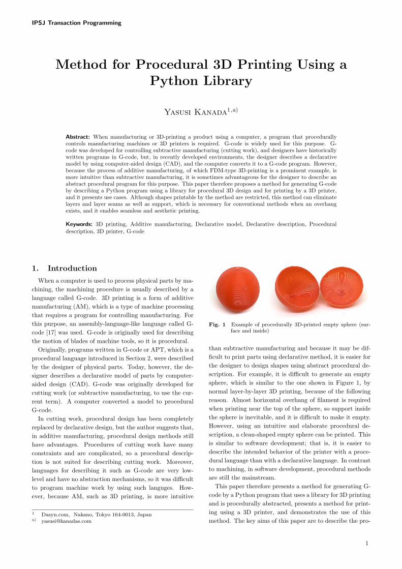
Fig. 1 Example of procedurally 3D-printed empty sphere (sur-face and inside)
than subtractive manufacturing and because it may be dif-ficult to print parts using declarative method, it is easier forthe designer to design shapes using abstract procedural de-scription. For example, it is difficult to generate an emptysphere, which is similar to the one shown in Figure 1, bynormal layer-by-layer 3D printing, because of the followingreason. Almost horizontal overhang of filament is requiredwhen printing near the top of the sphere, so support insidethe sphere is inevitable, and it is difficult to make it empty.However, using an intuitive and elaborate procedural de-scription, a clean-shaped empty sphere can be printed. Thisis similar to software development; that is, it is easier todescribe the intended behavior of the printer with a proce-dural language than with a declarative language. In contrastto machining, in software development, procedural methodsare still the mainstream.
This paper therefore presents a method for generating G-code by a Python program that uses a library for 3D printingand is procedurally abstracted, presents a method for print-ing using a 3D printer, and demonstrates the use of thismethod. The key aims of this paper are to describe the pro-
1

IPSJ Transaction Programming
posed method from the viewpoint of programming and toposition the method in the history of machining and in therange of conventional methods. In Section 2, the history ofprocedural cutting work, the basic method for 3D printing,and the programming method for 3D printing are described.The procedural 3D printing method using a Python library,which was developed by the author, is described in Section 3,and the experimental use of procedural 3D printing is intro-duced in Section 4. Related work is briefly described inSection 5, and Section 6 concludes the paper.
2. Conventional Cutting Work and Ad-
ditive Manufacturing
This section examines the value of procedural descrip-tion in machining and describes practices of 3D printing.First, the history of machining is reexamined, and second,the 3D printing method and programming 3D printers aredescribed.
2.1 History of procedural cutting work
The technologies of cutting work using computerized nu-merial control (CNC) and a programming language calledAPT for CNC were developed from the 1940s to the 1950s.The technology of numerical control was invented by JohnT. Parsons in 1942, and based on this technology, the tech-nology of CNC was developed at the Massachusetts Insti-tute of Technology (MIT) [24]. For the control of cuttingwork, a programming language called APT [1][20][7] wasdeveloped at MIT, and it was used for programming cut-ting work. Like an assembly language, APT is procedual.Parsons used punch cards to record CNC programs, butpaper tapes were used at MIT for this purpose. MIT re-searchers developed various subroutines and primitive pro-cedural abstraction mechanisms such as macros or nesteddefinitions [20]. In the 1970s, the relationships between APTand data abstraction or object-orientedness were discussed[20].
However, after initial CAD technologies were developed,designers of physical parts seldom ran machines using pro-cedural methods. The designers described declarative mod-els, and computers converted them to procedural programs.Declarative methods were used probably because of the com-plex nature of cutting work, which is not amenable to pro-cedural description or the low-level and weak abstractionfunctions of G-code and APT. Despite the various improve-ments to APT, certain limitations, such as compatibility,remained. It was likely difficult for designers to programcutting machines using APT.
2.2 Conventional 3D printing and g-code
When using a 3D printer to shape a 3D object, a modelis typically designed by a 3D CAD tool and horizontallysliced by a program called a slicer; the result is sent to a3D printer, and it is printed. When using a CAD tool, themodel is usually procedurally designed using a graphical userinterface, but the model itself is declarative. For example,
Fig. 2 FDM-type 3D printers (FDM by “Zureks” by Zureks -Wikimedia Commons)
a 3D design tool called OpenSCAD [23], which is a CADtool used for 3D printing, is unique because, in this environ-ment, a model is described using a programming language;however, this description is still declarative. The output fileformats varies among CAD tools, but a standard declara-tive format called STL (Standard Triangulation Languageor Stereo-Lithography) [25] is used to send data to a slicer.STL approximates the surface shape of models by a collec-tion of triangles. It does not express the internal structureof models.
There are many types of 3D printers. The cheapest type,which is widely used (and used in this study), is called fuseddeposition modeling (FDM). This type of printers extrudesmelted filament (plastic) from the nozzle and solidify it (Fig-ure 2).
Conventional 3D printers basially print objects on a layer-by-layer, but G-code itself is not constrained by the conceptof layer. The result of slicing is usually expressed by G-code, and it specifies the behaviour of the print head, theextrusion speed of plastic, and so on. 3D printers typicallyprint horizontally and layer by layer, so they do not usuallymove the print heads vertically, except when transitioningbetween layers. However, because G-code is not restrictedby the concept of layer, they do have the capacity to movethe heads much more freely.
Two examples of G-code commands are shown below.First, a command named G0 specifies a simple tool (head)motion. For example, command “G0 X1 Y2 Z3 F3600” de-scribes a motion at the rate of 3600 mm/min to location(1, 2, 3). Second, a command named G1 specifies cuttingand moving operations for a cutting machine and printingand moving operations for a 3D printer. For example, com-mand “G1 X1 Y2 Z3 F3600 E100” describes printing withthe extrusion amount of filament specified by “E100” whilemoving to location (1, 2, 3). (The amount of filament isspecified by an absolute or relative value.) In both G0 andG1, there are no constraints on direction of motion.
3. Development of Method for Procedu-
ral 3D Printing
A method of procedural 3D printing using Python as thebase language is proposed. In this section, the language andthe method for 3D printing using Python are described.
2

IPSJ Transaction Programming
3.1 Python-based description method
In contrast to cutting work, the machining process in ad-ditive manufacturing is relatively intuitive, so it is usefulfor the designer to describe the model procedurally, as ex-plained in Section 1. Therefore, a Python library (appli-cation programming interface (API)) is proposed for thispurpose. By using a procedural abstraction function (i.e.,functions and methods), which is common in programminglanguages, modular 3D printing, which cannot be describedby G-code, can be achieved.
Python is used for describing the library in stead of a lan-guage conventionally used for machining, such as APT, forthe following reasons. APT was improved and updated tohave some abstraction functions, so it is not impossible to beused for 3D printing. However, instead of extending APT,it is probably better to use a languge such as Python as thebase for procedural 3D printing for two reasons. First, it isconsidered more effective to employ a widely used languagebased on modern syntax and semantics. Second, a modernlanguage such as Python has required language functionssuch as procedural abstraction, so it is not necessary to ex-tend the language but only to add a library. Many otherlanguages satisfy these conditions, but Python is selectedas the base language because it is more widely and inter-nationally used than the alternatives. Because APT cannotbe executed by manufacturing machines, a file with an in-termediate format called Cutter Location (CL) is obtainedwhen executing an APT program. In the same way, in theproposed method, a G-code file is generated by executing aprogram written in Python.
Two libraries for procedural 3D printing were developed.They are draw3dp.py, which is used for 3D model generationby assembling and deforming parts, and turtle.py, whichis used for model generation by 3D turtle graphics. Thelatter (published in http://www.kanadas.com/program-e/2014/08/a python library for 3d turtle.html) is a libraryfor 3D turtle graphics. The method for drawing graphicsby using turtle.py is close to that of LOGO [18], but it isused for 3D printing. The coordinate used for this libraryis turtle centered (i.e., similar to that used for a flight sim-ulator), and the turtle creates the shapes of parts directly.The location of the print head is always the zero point, andits direction of motion is always forward [8][9].
In contrast, draw3dp.py (published inhttp://www.kanadas.com/program-e/2014/10/3d printing library for parts.html) is based on Carte-sian coordinate. This feature is similar to its counterpart inProcessing [19], MetaPost [6], or Asymptote [22]. However,there is an important difference between this library andthese languages. In the former, as described below, shapesare generated by a procedural method, that is, the stackingof directed strings (lines), which is 3D-printing oriented. Inthis library, an object surface is thus generated by stackingstrings. In contrast, in the latter, surfaces are a primitiveand lines have no direction. The programming langugeavailable in OpenSCAD [23] is designed according to the
same principle. In draw3dp.py, a shape can therefore bedirectly mapped to a 3D-prining procedure, but in thelanguages listed above, including OpenSCAD, it cannot bedirectly mapped to a 3D-printing procedure. Therefore, inthe case of OpenSCAD, as in other CAD tools, to enableprinting models, a program called a slicer, which convertsa model to a printable form, is required. Printing failswhen the slicer works in a manner that diverges from theintention of the model designer, as in the case of the emptysphere described in the introduction. In contrast, theprinter works according to the designer’s intention whenusing draw3dp.py.
Figure 3 summarizes the APIs included in draw3dp.py.The APIs for assembling parts (2D and 3D shape genera-tion) [10] are explained in Section 3.3, and the APIs for de-forming parts [12] are explained in Section 3.4. The API formodulating parts (part surfaces) is explained in Section 3.5.
3.2 Part representation and generation
3D printers, including the FDM-type, stack strings of ma-terials (these strings are called “filaments” in FDM). Indraw3dp.py, a part is thus represented by a sequence ofstrings Si, (S1, S2, ..., Sn) [12].
Si = (Pstarti, P endi, ci, vi)
In this expression, Pstarti denotes the start point andPendi denotes the end point of the string. (They are as-sumed to be connected by a straight line.) Moreover, ci
denotes the cross section of the string (which can be re-placed by a parameter of filament density), and vi denotesthe printing speed (mm/sec), that is, the velocity of thehead motion. Although vi is conceptually unnecessary, it ispractically convenient. A sequence of strings represents anobject (model), and it depends on the procedural genera-tion of the object. Each string and a sequence of strings canbe regarded as programs. These programs are converted toG-code before executing them.
In this representation, the direction of the filament in eachlocation inside the part is specified. If the part is thick, notonly the surface shape but also the structure and densityof the filament in each internal location of the part can bespecified. These parameters cannot be described by con-ventional CAD models or STL. The original purpose of thestring-based representation presented above is to utilize thedirection of the filament in 3D prinitng for expressions ofobjects (e.g., for an aesthetic purpose) [10][12].
Parts are treated as objects (in the sense of object-oriented design), and the class name for parts is Trace. Forthis purpose, first, the constructor, draw3dp.Trace, is usedto generate an empty part. (See Figure 3, which also illus-trates the methods described below.)
In the current version, the library contains a limited num-ber of simple parts, such as circle, spiral, and helix; however,shapes that are not combinations of these shapes can alsobe described using low-level methods such as line genera-tion. Programs that represents abstract high-level parts but
3

IPSJ Transaction Programming
• Constructor: part = draw3dp.Trace(crossSection, x, y, z)
Generate an empty part and specify the start point (current
location) and the cross section.
• Low-level functions
– Motion: part.move(x, y, z)
Move linearly from the current location to (x, y, z), which is
the next location to extrude filament.
– Line generation: part.draw(x, y, z)
Generate a string and add it to the part while moving linearly
to (x, y, z).
– String cross section configuration: part.setCrossSection(c)
or part.thickness(c)
Set the cross section of the string used for part to c from now
on.
– Print speed configuration: part.setVelocity(v) or
part.speed(v)
Set the print speed of the part to v from now on.
• Two-dimensional part generation (parts assembly)
– Circle generation: part.circle(r, x, y, z)
Add a circle with center location (x, y, z) and radius r to
the part.
– Spiral generation: part.spiral(r, hpitch, x, y, z)
Add a spiral with center (x, y, z) and radius r to the part.
(hpitch is the horizontal pitch of the string).
• Three-dimensional part generation (parts assembly)
– Helix generation: part.helix(r, h, vpitch, x, y, z)
Add a helix with center (x, y, z), radius r, and height h to
part (vpitch is the vertical pitch of the string).
– Cylinder generation: part.cylinder(r, h, vpitch, hpitch, x, y,
z)
Add a filled cylinder with center (x, y, z), radius r, and
height h to the part (vpitch and hpitch are vertical and hor-
izontal pitch).
• Part deformation
– Deformation by Cartesian coordinates: part.deform xyz(fd,
fc, fv)
Map the Cartesian coordinates of part before and after the
deformation by function fd, and convert the cross section by
function fc and printing speed by function fv.
– Deformation by cylinder coordinates:
part.deform cylinder(fd, fc, fv)
Map the cylinder coordinates of part before and after the
deformation by function fd, and convert the cross section by
function fc and printing speed by function fv.
• Modulation of part (surface)
– Modulation by cylinder coordinates:
part.modulate cylinder(fm)
Modulate part by function fm (generate texture on the part
surface).
• G-code generation: part.draw()
Generate G-code to print part (finalize the part).
Fig. 3 Major APIs of procedural 3D printing
(a) Spiral (b) Helix
Fig. 4 Spiral and helix
that cannot be described by high-level library functions ormethods can be described using low-level library functionsin the same way as conventional procedural programs.
High-level parts were gradually added to the library. Theaddition is intended to extend the library by adding use-ful parts. However, in the current version, because shapessuch as arcs are not supported, the programmer (designer)must describe them using the low-level APIs. Available low-level methods include draw, which draws a straight line tothe specified location (which corresponds to G1), and move,which moves the head to the specified location without ex-truding filament (which corresponds to G0). The cross sec-tion of a string and the printing speed should also be con-trolled by using low-level methods.
The library includes a method called circle, which candraw a circle easily. Because a string is a line, a circle is ap-proximated by lines. Because 3D printers cannot typicallydraw exact arcs, this approximated shape represents botha limitation of string-based expression and a limitation ofcurrent 3D printers. The number of strings that forms acircle can also be given by a parameter. However, if a circleconsists of many and excessively short strings, the printingspeed becomes lower than specified, and the printing workmay stop or become unstable.
The library also includes a method called spiral, accord-ing to which single spiral can be drawn (See Figure 4(a)).A more complicated part generation method, helix, is alsoincluded in the library. This method generates unnested he-lix, that is, an empty cylinder without a bottom. It cangenerate a thin cylinder of any height, with no layers andhence no seams between layers.
In contrast to a single cylider generated by method he-
lix, method cylinder generates a filled cylinder. However,seams cannot be avoided completely when printing a filledcylinder.
All the methods explained above prints objects helicallyor spirally from the bottom to the top. By printing heli-cally, new filament can be supported by the filament below,which can eliminate the inter-layer seams which are oftengenerated by 3D printing [13]. Printing a helix (or a spiral)is, therefore, considered to be the most important functionin procedural 3D printing.
3.3 Parts assembly
When creating a product or a prototype using machineprocessing, the normal process is to generate the parts firstand then to assemble them. In subtractive manufacturing,parts are assembled after the cutting process; however, whenusing AM, multiple parts are often generated at once. In-
4

IPSJ Transaction Programming
Fig. 5 Olympic symbol printed as a collection of splitted andassembled rings
stead of printing part by part, all preassembled parts areprinted concurrently. Such combinations are enabled by con-ventional 3D design and printing methods. The proposedlibrary may also be used for printing assembled parts, al-though there are currently many limitations on the combi-nations.
When using the proposed library, if the parts satisfy thefollowing two conditions, they can be assembled by printingthem sequentially.• The print head is not disturbed by previously printed
filaments.• Printed filaments are supported by the print bed or pre-
viously printed filament.Note that the processes for testing these conditions are notyet automated.
If the above conditions cannot be satisfied even by chang-ing the printing order, the conditions are to be testedwhether they are satisfied or not by dividing a part andthe printing order [10]. For example, a chain of rings cannotbe printed procedurally unless the rings are divided. Thus,in a previous paper [10], a 3D-shaped (chained) Olympicsymbol was attempted by dividing the ring manually (be-cause not yet automated) (Figure 5). However, because anOlympic symbol cannot be represented by a combination ofparts introduced in Section 3.2, specialized parts (generationfunctions) were required. In addition, this Olympic symbolhad to be printed without contact with the print bed, sosupport material was required.
By introducing functions with part-assembly procedures,the functions will become generation functions of complexparts. They represent procedurally abstracted modularstructures (of programs and printed parts).
3.4 Deformation of objects
In the library draw3dp.py, a part generated by 3D- or 2D-generation functions can be deformed before it is printed.Deformation is introduced because only a limited numberof simple shapes are manually registered in this library,and thus it is difficult to generate various shapes throughassembly alone. If a part or a combination of parts canbe freely deformed, especially by applying nonlinear trans-formations, various shapes can be relatively easily created.In conventional CAD tools, linear transformations such astranslation, rotation, enlargement, and reduction, can beapplied to models. The OpenSCAD lauguage, which wasmentioned in Section 3.1, can also apply these transforma-tions. However, they can be applied only to declarativelydefined parts. In contrast, in draw3dp.py, procedurally de-
fined parts, which are defined as a sequence of strings, canbe deformed. Because a part can be regarded as a programas described before, this deformation can be regarded as aprogram transfomation. In computer graphics, a freer defor-mation is important [21][2], but deformations operate onlyon declaratively defined shapes. Deformation operation notonly has the ability to create various shapes, but can alsopreserve 3D-printable [12] parts, and the printability can bepreserved by using these parts.
In draw3dp.py, two methods, deform xyz and de-
form cylinder, are supplied for deformation, and methoddraw is used for fixing the shape of the part (to generate G-code) (see Figure 3). Two of the deformation methods havethe same function; however, both methods are prepared inorder to facilitate the used of Cartesian coordinates in somecases and the use of cylinder coordinates in others [12].
Method part.deform xyz(fd, fc, fv) deforms part based onCartesian coordinates. Function fd(x, y, z) (the first argu-ment) maps a location (x, y, z) before the deformation toa location after the deformation. Function fd, thus, returnsthree values. Function fc(c, x, y, z) (the second argument)maps a cross section c before the deformation to a crosssection after the deformation. Function fv(v, x, y, z) (thethird argument) maps a printing speed (head-motion speed)v to a printing speed after the deformation. Because there iscurrently no way to preserve 3D printability automatically,the part designer must define appropriate functions fc andfv to preserve it.
Method part.deform cylinder(fd, fc, fv) deforms part ac-cording to the cylinder coordinates. The function of thismethod is the same as deform xyz, with the exception thatthe coordinates are different. Most of the currently definedparts are printed helically, so this method, which is basedon cylinder coordinates, is more useful than that based onCartesian coordinates.
These deformation methods transform the coordinates ofthe start and end points of strings. These transformationsmap straight lines, that is, strings, to straight lines, so theerrors of midpoints of the strings vary. To preserve printabi-ity, the transformation function should be continuous, andenlargement and reduction should be suppressed by thesetransformations because enlargement or reduction causes er-rors, which may spoil printability (i.e., disable printing).
Examples of deformation are shown in Figures 6 and 7. A3D-printing tool called Repetier Host was used to visualizethe models in these figures.
Figure 6 shows a cup, which consists of a helix and thincylinder (bottom), and a shape that is a deformation of thecup. The cup in Figure 6(a) becomes the plate shown inFigure 6(b) by applying the following deformation:
deform cylinder(fdd, fcd, fvd),where fdd(r, θ, z) = (r + 1.05z, θ, 0.3z),fcd(c, r, θ, z) = 0.96 c, and fvd(v, r, θ, z) = v.
Note that the size of the deformed bottom must fit theshape, that is, deformed helix.
Figure 7 shows a helix and a sphere; the latter is generated
5

IPSJ Transaction Programming
(a) Cup before deformation
(b) Plate after deformation
Fig. 6 Example of deformation from a cup
(a) Helix before deformation (b) Sphere after deromation
Fig. 7 Example of deformation from helix
by deforming the helix. Figure 7(a) shows the original helix,from which the sphere shown in Figure 7(b) is obtained bydeformation. This deformation is based on the following ex-pression, where the pitch of the filament is preserved (thatis, this transformation does not enlarge or reduce the helixvertically, but it just twist around a sphere).
deform cylinder(fds, fcs, fvs),where fds(r, θ, z) = (Radius * sin(π z/cylinderHeight),
θ, r ― Radius * cos(π z/cylinderHeight)),fcs(c, r, θ, z) = 1.2 c, andfvs(v, r, θ, z) = 1.2 * ((fr(r, θ, z)/Radius)**2 + 0.1) v,
where parameter cylinderHeight denotes the height of thehelix before the deformation, and the length is equal to thehalf of the meridian length after the transformation. Severalother examples were shown in a previous paper [12].
3.5 Texture map by modulation of printing
The proposed 3D-printing method can be relatively eas-ily extended by drawing (mapping) characters, images, ortextures on the surface of objects to be printed by control-ling the printing process. This method generates asperity bychanging the cross section of filament [14]. An application ofthis method is called modulation of printing [14]. Althoughchanging the cross section while printing cannot generate
Fig. 8 Binary-valued bitmapped map
deep asperity, it can generate shallow asperity.There are two ways to change the cross section of filament.• Changing the extrusion speed of filament.• Changing the motion speed of the print head.
The first way is more direct; however, the second way isused in the present study because it has better responsive-ness. Concerning 3D printers, delay of extrusion, that is, thetime from motion change of the extruder, which extrudes thefilament, to the change of filament extrusion, is lengthy. Itmay be several seconds. The first method is thus limitedby slow responsiveness. Although the print head of a 3Dprinter has a high level of inertia, it responds much morequickly to a motion-speed change. The second method isthus suited for generating shallow asperity. The proposedlibrary thus uses this method. Method modulate cylinder isdefined for modulation (See Figure 3).
The example of modulation by a map is described below.If a plain surface is modulated by a map, the map isprinted as is. In contrast, if a sphere is modulated, aglobe can be printed. Figure 8 shows a binary-valuedworld map generated from a world map by equidis-tant cylindrical projection based on data from NASA,which can be obtained from the Celsia Motherload(http://www.celestiamotherlode.net/catalog/earth.php).This site contains various maps with various processingand various bitmap sizes. The size of the map shown inFigure 8 is 300 × 150. Therefore, each dot in a bitmapshould be mapped to an area with 1.2◦ of longitude and1.2◦ of latitude. Each circle of the globe should consist of300 strings; a sphere is generated with 150 circles, and eachdot on the map is mapped to a string on the globe. Thatis, the printing speed of each part of the string is selectedfrom two values.
3.6 Program example
Because it may be difficult to grasp the entire model gen-eration and printing process, the process is explained usingthe program below, which prints a sphere. After this pro-gram configures constants and parameters, it calls methodinit for overall initialization (but especially for initializationof the 3D printer). The program prints a so-called “skirt”.A skirt is extra filament around the printing area, which isgenerated before the part is printed. It is printed for the sakeof stabilizing the state of the print head and filament. The
6

IPSJ Transaction Programming
import draw3dpfrom math import sin, cos## Constant ##PI = 3.14159265359## Printer parameters ##IsABS = False # Using PLA as the materialDefaultVelocity = 40 # mm/sec## Printing parameters ##x0 = 0; y0 = 0; z0 = 0.4## Extrusion parameters ##defaultCrossSection = 0.196 # mm2 (Radius 0.5 mm)FilamentDiameter = 1.75 # mm (Normally 1.75 mm or 3 mm)## Temperature patameters ##if IsABS:
HeadTemperature = 235# ABS requires slightly highter temperature
BedTemperature = 90 # ABS requieres heating printbedelse: # PLA
HeadTemperature = 220BedTemperature = 35
# Close to room temperature for PLA
## Initialize ##draw3dp.init(FilamentDiameter, HeadTemperature,
BedTemperature, DefaultVelocity)## Generate and print skirt ##sk = draw3dp.Trace(defaultCrossSection, 0, 0, 0.4)skirt2(sk) # Definition if skirt2 is omittedsk.draw(0.4)
## Generate object to be printed ##obj = draw3dp.Trace(defaultCrossSection, x0, y0, 0.4)radius = 25.0helixHeight = PI/2 * radiusrmax = 30.0vpitch = 0.2; x0 = 0; y0 = 0; z0 = 0.4obj.setVelocity(36) # Initial printing speed configurationobj.helix(radius, helixHeight, vpitch, x0, y0, 0)
# Generate helixobj.deform cylinder(
lambda r, theta, z:(radius * sin(PI*z/helixHeight), theta,r - radius * cos(PI*z/helixHeight)),
lambda v, r, theta, z: v,lambda c, r, theta, z:
0.35 * ((0.5 * r + radius) / radius) * c) # Deformation 1obj.deform cylinder(
lambda r, theta, z: (r, theta, z + z0),lambda v, r, theta, z: 0.6 * ((r/radius)**1.5 + 0.2) * v,lambda c, r, theta, z: 2.0 * c) # Deformation 2
## Print ##obj.draw()
Fig. 9 Program for printing empty sphere
(a) Four-cycle plate (b) Three-cycle plate
(c) Heart-shaped plate
(d) Vase
Fig. 10 Plates and pods
part to be printed is named “obj”. “Obj” is initially emptybut becomes a helix (by the addition of strings that form ahelix by method helix), and it is deformed to a sphere by ap-plying method deform cyliner twice. The main deformationis performed by the first application, but it is slightly movedto z direction and the printing speed and filament-extrusionspeed are adjusted by the second application. Finally, thestrings are converted to G-code using method draw.
4. Practice of Procedural 3D Printing
By using the method described in the previous sec-tion, small plates, pods, spheres, and globes, whichcan be printed in 10 to 20 minutes, were manufac-tured. Although the products shown in this sec-tion are not intended for real-world use, readers canobtain all of these samples (http://bit.ly/1EZ4SZI orhttp://store.shopping.yahoo.co.jp/dasyn/).
4.1 Plates and pods generated from cup
Plates and pods with various shapes generated using themethod described in Section 3.4 are shown in Figure 10. Fig-ures 10(a) and (b) show plates [3], which are deformed from ahelix as shown in Figure 6(b). Even when winding filamentsmostly horizontally, no support material, which may makethe printed object cloudy, is required. Figures 10(a) shows a
7

IPSJ Transaction Programming
Fig. 11 Sphere and deformed sphere
four-cycle plate (i.e., with four trigonometric-function-basedcyclic motions), and Figures 10(b) shows a three-cycle plate.Both specify a trigonometric function in function fd, whichis an argument of method deform cylinder. Because the an-gle of plate surface and filament density varies from locationto location, the reflection of light also varies [12]. Such reflec-tion or brightness is generated using pure and transparentpolylactic acid (PLA) and by eliminating support material.No such reflection is generated by colored plastics.
Figure 10(c) shows a plate generated by using a transfor-mation from a circular helix to a heart-shaped helix [4]. Thefollowing function, which converts a circle to a heart shape,is used.
fdh(x, y, z) = (x + b z sqrt(abs(y) / radius), y, z)This shape is based on the equation of a heart-shaped
curve [26]. An appropriate range of b is 0−1.2. This trans-formation becomes an identity function if b z = 0 holds,and it generates a sharper heart shape if the value of b − z
becomes large. The helix is deformed using this functionand deform xyz. The shape of the horizontal cross sectionis a circle at the bottom, and it becomes sharper toward thetop because the value of b − z increases monotonically. Bychanging the maximum value of b, the various shapes shownin Figure 10(c) are generated. Moreover, as Figure 10(c)shows, the gradient and reflection of plate parts are variedby adding small verticall oscillations using a trigonomet-ric function. Figure 10(d) shows two types of vases. Theleft vase [14] is generated by radius-direction and vertical-direction deformations using trigonometric functions. Theright vase is generated by twisting the same heart-shapedhelix (that is, the direction of the heart changes accordingto the height).
4.2 Helix-based spheres and other objects
As explained in Section 3.4, a sphere can be generated bydeforming a helix. The left photo in Figure 11 shows a sim-ple sphere generated by this method. Because it is not pos-sible to support it at single point (i.e., the south pole) whenprinting it, a special technique for support is required. How-ever, no support in the conventional meaning is used [12].The right photo in Figure 11 shows an object generated byfurther deforming a sphere using a trigonometric functionin the same way for the objects shown in Figures 10(a) and(b).
Fig. 12 Modulated sphere (globe) and bowl
Fig. 13 Shade for small lamp
Figure 12 shows objects generated with the modulationtechnique that uses a bitmap, which is described in Sec-tion 3.5. The left photo shows a globe [5], which was gener-ated by modulating a sphere by a map. The whole sphere isilluminated by only one LED placed below the sphere [15].The right photo shows a half-sphere-shaped bowl (more pre-cisely, a half sphere and a stand) modulated by alphabets.(This bowl was printed upside down.)
When printing a globe, the printing speed of each stringis selected from two alternative values. The printing mayfail if the ratio of the cross sections of sea and land is toolarge. An appropriate ratio is 1 to 0.6 or 1 to 0.7.
As described above, when using a bitmap of 300 × 150,each string cycle is divided into 300 short strings. However,near the poles, the strings are too short, so the number ofstrings is reduced. It is possible for reducing them whengenerating the globe model, but, because method draw hasa function to reduce the number of connected short strings,the model representation does not to be changed.
Figure 13 shows small shades [11] for LED bulbs gener-ated from a helix. The left photo shows a shape generatedby deforming a partial sphere using trigonometric functions.The right photo shows a shape generated by modulating thesame partial sphere using trigonometric functions. Most ofthe materials for FDM-type 3D printing become weak in thepresense of heat, so they are not suited for filament lamps;however, even PLA can be used for LED shades becauseLEDs generate less heat. These shades are largest of theobjects shown in this section (but their diameter is about100 mm), but the printing time is around 20 minutes. Theprinting time is shorter than in conventional 3D printingbecause the shades are thin (the filament is unnested), buttheir relatively strong intensity protects them from beging
8
IPSJ Transaction Programming
easily broken even if dropped. (This is is the case for otherobjects as well.)
5. Related Work
The proposed method is characterized by modeling ob-jects to be 3D printed using a combination of proceduralparts, which are printed helically or spirally. In the ex-amples shown in the previous section, filament is stackedseamlessly and in an aesthetically pleasing manner. Klein,et al. [16] established a method for the helical 3D printingof transparent glass. The objects printed according to thismethod are seamless and aesthetically pleasing. The pho-tos in their paper shows aesthetic effects of light reflectionand refraction. However, they did not mention the designmethod used for their work.
6. Conclusion
Current design methods for 3D printing are declarative,and procedural description by designers has not been suc-ceeded in cutting work. However, the author suggests thatprocedural description is advantageous in additive manufac-turing. Thus, libraries for procedural 3D printing are de-veloped, as is a method for 3D printing, in which G-codeprograms are generated by this method and procedurallyabstacted Python programs. Although printable shapes arerestricted when using this method, layers and layer seamscan be eliminated, as can the support materials requiredfor conventional methods eliminated, and seamless and aes-thetically pleasing printing is enabled by this method. Theauthor intends to disseminate this method and the librarythrough this paper.
References
[1] Brown, S. A., Drayton, C. E., and Mittman, B.: A Descrip-tion of the APT Language, Communications of the ACM,Vol. 6, No. 11, pp. 649–658 (1963).
[2] Coquillart, S.: Extended free-form deformation: a sculptur-ing tool for 3D geometric modeling, ACM SIGGRAPH Com-puter Graphics, Vol. 24, No. 4, pp. 187–196 (1990).
[3] Dasyn.com: Printing a dish by helical 3D-printing method,http://youtu.be/5P1vaahzW98
[4] Dasyn.com: 3D-printing a dish with various heart shapes,http://youtu.be/G9x14DZYN 8
[5] Dasyn.com: Creating a Globe by Helical 3D-printingMethod, http://youtu.be/YWx1vqig2-o
[6] Hobby, J. D.: METAPOST: A User’s Manual, version 1.999(2014).
[7] ISO: Numerical Control of Machines – NC Processor Input– Basic Part Program Reference Language, ISO 4342:1985(1985).
[8] Kanada, Y.: “Three-dimensional Turtle Graphics” by 3DPrinters, IPSJ Summer Programming Symposium (2014), inJapanese.
[9] Kanada, Y.: “3D Turtle Graphics” by using a 3D Printer,Int. Journal of Engineering Research and Applications, Vol.5, No. 4 (Part-5), pp.70–77 (2015).
[10] Kanada, Y.: Method of Designing, Partitioning, and Printing3D Objects with Specified Printing Direction, 2014 Interna-tional Symposium on Flexible Automation (ISFA) (2014).
[11] Kanada, Y.: Photos of LED lamps with 3D-printed shades,Blog from Kanada, December 13, 2014 (2014), in Japanese.
[12] Kanada, Y.: Support-less Horizontal Filament-stacking byLayer-less FDM, International Solid Free-form FabricationSymposium 2015 (2015).
[13] Kanada, Y.: Making Plates by a 3D Printer without Sup-
port, I/O, April 2015, pp. 15–17 (2015), in Japanese.[14] Kanada, Y.: Creating Thin Objects with Bit-mapped Pic-
tures / Characters by FDM Helical 3D Printing, 8th Int ’lConference on Leading Edge Manufacturing in 21st Century(LEM21) (2015).
[15] Kanada, Y.: Designing 3D-Printable Generative Art by3D Turtle Graphics and Assembly-and-Deformation, XIIIVGenerative Art Conference (GA 2015) (2015).
[16] Klein, J., Michael, S., Giorgia, F., Markus, K., Chikara, I.,Shreya, D., James, C. W., Peter, H., Paolo, C., Yang Maria,and Neri, O., 3D Printing and Additive Manufacturing, Vol.2, No. 3, pp. 92–105 (2015).
[17] Kramer, T. R., Proctor, F. M., and Messina, E.: The NISTRS274NGC Interpreter - Version 3, NISTIR 6556 (2000).
[18] Papert, S. A.: Mindstorms: Children, Computers and Pow-erful Ideas: All About Logo, How It Was Invented and HowIt Works, Basic Books (1993).
[19] Pearson, M.: Generative Art: A Practical Guide Using Pro-cessing, Manning Publishing Co. (2011).
[20] Ross, D. T.: Origins of the APT Language for AutomaticallyProgrammed Tools, ACM SIGPLAN Notices, Vol. 13, No. 8,pp. 61–99 (1978).
[21] Sederberg, T. W. and Parry, S. R.: Free-form deformation ofsolid geometric models, ACM SIGGRAPH Computer Graph-ics, Vol. 20, No. 4, pp. 151–160 (1986).
[22] Staats III, C.: An Asymptote Tutorial,https://math.uchicago.edu/c̃staats/Charles Staats III/Notes and papers files/asymptote tutorial.pdf (2015).
[23] WikiBooks: OpenSCAD User Manual, available athttp://en.wikibooks.org/wiki/OpenSCAD User Manual
[24] Wikipedia: History of Numerical Control,http://en.wikipedia.org/wiki/History of numerical control
[25] Wikipedia: STL (file format),http://en.wikipedia.org/wiki/STL (file format)
[26] Yamamoto, N.: Heart-shaped Curves,http://www.geocities.jp/nyjp07/heart/index heart.html,in Japanese.
m Yasusi Kanada
Yasusi Kanada was born in 1956. He received a B.E. degree inmathematical engineering from University of Tokyo in 1979 and anM.E. degree in information engineering from University of Tokyoin 1981. He has been working for Hitachi, Ltd. (Central ResearchLaboratory, Systems Development Laboratory, and Technology In-novation Center) since 1981. He stayed in Carnegie Mellon Univer-sity from 1988 to 1990, and stayed in Tsukuba Laboratory of RealWorld Computing Partnership (RWCP) from 1992 to 1995. He isa part-time lecturer of Kogakuin University. He received a Ph.D(Engineering) from University of Tokyo in 1992. His work includesdevelopments of Fortran compilers, vectorized symbolic processingand logic language processing, an emergent computation model,information extraction/search/organization, virtual-environment-based communication, policy-based networking, network virtual-ization, and deep-learning-based computer vision. He is a mem-ber of ACM,IEEE (Computer, ComSoc, SMC),Japan Societyfor Software Science and Technology, Japan Society for ArtificialIntelligence, and Japan Society of Mechanical Engineers.
9