method of model numbering 2 for valve type fl 441 sp · pdf fileconstruction type b - bellows...
TRANSCRIPT

CONSTRUCTION TYPE
B - BELLOWS C - CONVENTIONAL O - OTHER, TO SPECIFY
SPRING MATERIAL
0 - OTHER, TO SPECIFY 1 - CS CD. PLATED 2 - HIGH TEMP. ALLOY 4 - STAINLESS STEEL
STANDARD ACCESSORIES
0 - OTHER, TO SPECIFY 2 - CLOSED, SCREWED CAP 4 - PACKED LEVER CAP
ORIFICE LETTERACC. TO API 526
H C C4 1 2 2 4 X3
74 C S6 4 A A 2
D, EFGHJ
K, LM, N, P
QRT
FLOW DIA 'do'ACC. TO TUV
182329374660749298125165
C4 - CS, ASTM A 216 WCB(SS 304 TRIM)
C6 - CS, ASTM A 216 WCB(SS 316 TRIM)
S4 - SS, ASTM A 351 CF 8(SS 304 TRIM)
S5 - SS, ASTM A 351 CF 8(SS 316 TRIM)
S6 - SS, ASTM A 351 CF 8M(SS 316 TRIM)
4L - SS, ASTM A 351 CF 3(SS 304 L TRIM)
6L - SS, ASTM A 351 CF 3M(SS 316 L TRIM)
00 - OTHER, TO SPECIFY HS - ASTM A 217 GR. WC6
(SS 316 TRIM)LS - ASTM A 352 GR. LCB
(SS 316 TRIM)AY - ALLOY - 20
(ALLOY - 20 TRIM)HY - HASTELLOY - 'C'
(HASTELLOY - 'C' TRIM)SP - SPECIALCI - CI TO IS 210
(SS 304 TRIM)
0 - OTHER, TO SPECIFY1 - OPEN BONNET2 - JACKETED TYPE3 - TEST GAG4 - 'O' RING DISC6 - STELLITED NOZZLE & DISC7 - COOLING SPACER8 - DRAIN PLUG
SPECIAL FEATURES/EXTRA ACCESSORIES 'X' FOLLOWED BY THE FOLLOWING NOS.
MATERIAL TYPECONNECTION RATING FOR
INLET & OUTLET
A - ANSI 150 #B - ANSI 300 #C - ANSI 600 #0 - OTHER, TO SPECIFY1 - PN 102 - PN 163 - PN 254 - PN 405 - PN 64
MODEL NO.H/CC41224X3
74/CS64AA2
Prefix ‘B’ is used in the 1st block along with orifice letter/flow dia for IBR (Indian Boiler Regulations) approved valves.
PROCEDURE FOR VALVE SIZING & SELECTION
Method of Model NumberingFor Valve Type FL 441 SP Series
2/01
First refer to Type FL 441, Standard Pressure Series. If the range is insufficient, refer to Type FL 441, High Presure Series...
Valves manufactured by FAINGER LESER based on DIN design are type tested & approved by the International Agency, TUV (the German Type Test approving Authority) and the local statutory bodies like the CCoE (Chief Controller of Explosives), the IBR (Indian Boiler Regulations Act, 1950) etc.
Sizing calculations are according to ASME Sec. VIII Div. 1 / API RP 520 or DIN 3320 / TRD 421, AD-Merkblatt 2000 - A2, ISO 4126, IBR 1950, where applicable. For IBR Valves of FAINGER LESER, the assigned value of constant is: C=38. Relieving capacity of the selected Valve would meet the customer required capacity.
Flange rating and center to face dimensions are according to API 526 / DIN 3320. Valves with special connections and different center to face dimensions can also be provided on request.
FAINGER LESER Valves are tested for seat leakage according to API 527.
FAINGER LESER April 2006
NOTE
API
TUV
2
FL 441
SP Series
Please refer to our new model Numbering
2
2/02
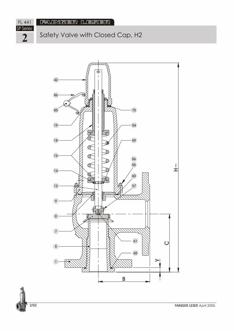
Safety Valve with Closed Cap, H2
H~
5918
B
1
5
8
7
9
14
12
16
61
C
60
Y
57
56
55
86
19
85
42
75
54
60
FAINGER LESER April 2006
FL 441
SP Series

42 Cap H2
Lever Cover H4Lever H4Lifting ForkShaftSpacerO-ringSupport Ring/GlandWasherHex. NutCirclip
41434445757980818283
Part Name
BodySeat/NozzleDiscGuideBonnetSpindleSplit RingSpring PlateAdjusting ScrewLock NutSpindle CapName PlateSpringStud Hex. NutRoll PinSecuring RingGasketBallPinLead SealSeal WireSecuring Ring
15789
121416181946505455565759606174858691
Item
Cap H2, Gastight
Lifting Device H4, Gastight
Assembly of Flanged Spring Loaded Safety Valve
2/03
46
91
74
16
12
54
59
5714
61
7
H2
42
H482
81
8380
4579 41
44
75
18
19
86
85
56
9
8
60
55
1
FAINGER LESER April 2006
2
FL 441
SP Series
5

STANDARD MATERIAL (Also Refer to Method of Model Numbering for Details)
C41 / C61 S44/S54/S64 SPECIAL-1 SPECIAL-2 SPECIAL-3PART NAMETYPE
PARTNo.
C
L O
S
E
D
C
A
P,
H 2
PAC
KED
LEVE
R, H
4
1
5
7
8
9
12
14
16
18
19
42
54
55
56
57
59
60
61
75
85
86
43
44
45
46
74
80
82
BODY
NOZZLE
DISC ASSEMBLY
SPINDLE GUIDE/
GUIDE INSERT
BONNET
SPINDLE
SPLIT RING
SPRING PLATE
ADJUSTING SCREW
LOCK NUT
CAP (41)
SPRING
STUD
HEX. NUT
ROLL PIN
SECURING RING
GASKET
BALL
SPACER
LEAD SEAL
SEAL WIRE
LEVER
LIFTING FORK
LEVER SHAFT
SPINDLE CAP
PIN
GLAND
HEX. NUT
A 216 Gr. WCB
AISI 304/316
AISI 304/316
A 216 Gr. WCB
AISI 304/316
A 216 Gr. WCB
AISI 304/316
AISI 304/316
CS CD. PLATED
AISI 304/316
AISI 304/316
A 216 Gr. WCB
CS CD. PLATED/
ALLOY STEEL
A 193 Gr. B7
A 194 Gr. 2H
SS
SS
C.A.F./Non Asb.
SS
C.A.F./Non Asb.
LEAD
MS
CS
SS
AISI 304/316
AISI 304/316
SS
CS
CS
A 351 CF 8/8M
AISI 304/316
AISI 304/316
A 351 CF 8/8M
AISI 304/316
A 351 CF 8/8M
AISI 304/316
AISI 304/316
AISI 304/316
AISI 304/316
AISI 304/316
A 351 CF 8/8M
SS/
ALLOY STEEL
A 193 B8/B8M
A 194 Gr. 8/8M
SS
SS
C.A.F./Non Asb.
SS
C.A.F./Non Asb.
LEAD
MS
CS
SS
AISI 304/316
AISI 304/316
SS
AISI 304/316
SS
A 217 Gr. WC6
AISI 316
AISI 316
A 216 Gr. WCB
AISI 316
A 217 Gr. WC6
AISI 316
AISI 316
CS CD. PLATED
AISI 316
AISI 316
A 216 Gr. WCB
ALLOY STEEL
A 193 Gr. B7
A 194 Gr. 2H
SS
SS
C.A.F./Non Asb.
SS
C.A.F./Non Asb.
LEAD
MS
CS
SS
AISI 316
AISI 316
SS
C.S.
C.S.
A 352 Gr. LCB
AISI 316
AISI 316
A 351 Gr. CF 8M
AISI 316
A 352 Gr. LCB
AISI 316
AISI 316
AISI 316
AISI 316
AISI 316
A 351 Gr. CF 8M
SS
A 193 Gr. B7
A 194 Gr. 2H
SS
SS
C.A.F./Non Asb.
SS
C.A.F./Non Asb.
LEAD
MS
CS
SS
AISI 316
AISI 316
SS
AISI 316
SS
A 351 Gr. CF 8/8M
Hastelloy-C
Hastelloy-C
A 351 Gr. CF 8/8M
AISI 316
A 351 Gr. CF 8/8M
AISI 316
AISI 316
AISI 316
AISI 316
AISI 316
A 351 Gr. CF 8/8M
SS
A 193 Gr. B8/B8M
A 194 Gr. 8/8M
SS
SS
Non Asb./PTFE
SS
Non Asb./PTFE
LEAD
MS
CS
SS
AISI 316
AISI 316
SS
AISI 316
SS
Standard Materials for Valve Type FL 441(Standard Pressure Series)
2/04
Material of construction will vary according to the service conditions and customer requirement. Other special materials,for example, Monel, Alloy-20, CF 3, CF 3M and accessories such as Balanced Bellows, Cooling Spacer, Test Gag, Heating Jacket,Drain Plug, Soft Seat (O-Ring) Disc etc. can be provided on request.
FAINGER LESER April 2006
NOTE
Note: The above material is for standard construction. Suitable material to be used for corrosion resistant/special application.
-60
-76
-10
14
200
392
300
572
540
1000
DIN 1.4310 (SS)
DIN 1.8159 (ALLOY STEEL)
DIN 1.1200 (CS)
-268
-268
-450
-450
-102
-151
-29
-21
427
800
540
10000F
0F
0C
0C
ASTM A 351 CF 8/8M
ASTM A 352 LCB ASTM A 216 WCB
ASTM A 217 WC6
TEMPERATURE Vs. MATERIAL OF CONSTRUCTION
SPRING
BODY
Standard Materials2
FL 441
SP Series

1
2
3
4
5
6
7
8
9
10
Sl.No.
InletSizemm
OutletSizemm
Max.Set Pr.bar g
25
32
40
50
65
80
100
125
150
200
40
50
65
80
100
125
150
200
250
300
40.0
40.0
40.0
40.0
40.0
40.0
40.0
40.0
25.0
20.0
WeightApprox.
kgs.
Height ‘H’ Approx.
12.0
17.0
22.0
30.0
45.0
70.0
98.0
140.0
165.0
295.0
340
440
480
540
645
760
800
860
985
1335
340
455
500
560
695
810
855
910
985
1335
Closed Cap, H2
mm
Packed LeverCap, H4
mm
114
121
121
124
165
210
229
241
267
279
105
124
124
137
156
197
181
240
240
276
11.0
11.0
11.0
11.0
16.0
18.0
18.0
20.0
20.0
20.0
Outlet"B"
mm
Inlet"C"mm
"Y"mm
domm
23
29
37
46
60
74
92
98
125
165
1
2
3
4
5
6
7
8
9
10
11
12
13
Sl.No.
InletSize
inches
OutletSize
inches
Max.Set Pr.bar g
Letter Area
sq. in.
Orifice Details
Area
sq. mm
Dia, "d"
mm
WeightApprox.
kgs.
Height ‘H’ Approx. Center to face
1
1
1½
1½
1½
2
2
3
3
3
4
4
4
4
6
6
8
2
2
2
3
3
3
3
4
4
4
6
6
6
6
8
10
10
40.0
40.0
40.0
40.0
20.0
40.0
20.0
40.0
40.0
20.0
40.0
40.0
40.0
40.0
40.0
25.0
20.0
D
E
F
G
H
H
J
J
K
L
L
M
N
P
Q
R
T
0.110
0.196
0.307
0.503
0.785
0.785
1.287
1.287
1.838
2.853
2.853
3.600
4.340
6.380
11.050
16.000
26.000
71.0
126.5
198.1
324.5
506.5
506.5
830.3
830.3
1185.8
1840.6
1840.6
2322.6
2800.0
4116.1
7129.0
10322.6
16774
9.50
12.70
15.88
20.33
25.40
25.40
32.51
32.51
38.86
48.41
48.41
54.38
59.70
72.40
95.30
114.60
141.72
12.0
12.0
14.0
16.0
20.0
22.0
24.0
30.0
38.0
48.0
52.0
56.0
75.0
98.0
140.0
165.0
185.0
340
340
360
360
440
445
490
490
550
645
665
665
760
800
860
985
1020
340
340
360
360
460
465
510
510
575
695
715
715
810
855
910
985
1020
114
114
121
121
124
124
124
143
162
165
184
184
210
229
241
267
279
105
105
124
124
130
137
137
137
156
156
178
178
197
181
240
240
276
11.0
11.0
11.0
11.0
11.0
11.0
11.0
13.0
14.0
16.0
16.0
16.0
18.0
18.0
20.0
20.0
20.0
Flange ratings and center to face dimensions are according to API RP 526 as applicable for Full Nozzle Safety Valves of inlet size 1" (25mm) and above. For revised sizes due to higher pressure & Temp., refer to page # 7/06. For smaller sizes, refer to FL 539 & FL 549 series.
Overall Dimensions
Closed Cap, H2
mm
PackedLever, H4
mm
Outlet"B"
mm
Inlet"C"mm
"Y"mm
2/05FAINGER LESER April 2006
NOTE
1. For API 526 (Orifice based) Valves
2. For “do” based Valves
Center to face
2
FL 441
SP Series

2
FL 441
SP Series
2/06
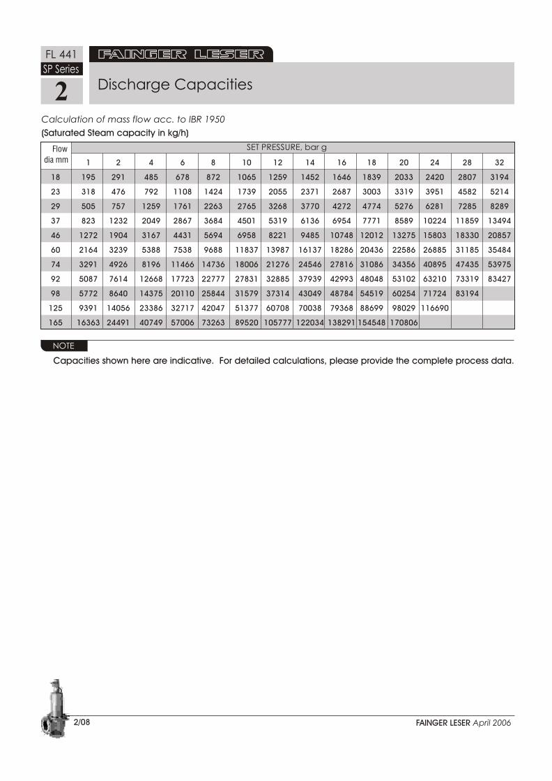
Discharge Capacities
FAINGER LESER April 2006
SET PRESSURE, psigOrifice MediumLetter 15 30 50 75 100 125 150 200 250 300 350 400 450 500 550 575
D Steam 172 263 385 537 689 841 993 1296 1600 1904 2208 2511 2815 3119 3423 3575
Air 65 94 137 192 246 300 354 463 571 680 788 897 1005 1114 1222 1276
Water 11 15 19 24 27 30 33 38 43 47 51 54 58 61 64 65
E Steam 307 469 686 957 1227 1498 1769 2310 2851 3392 3934 4475 5016 5558 6099 6370
Air 115 168 245 342 438 535 632 825 1018 1211 1405 1598 1791 1985 2178 2274
Water 19 27 34 42 48 54 59 69 77 84 91 97 103 108 114 116
F Steam 481 735 1074 1498 1922 2346 2770 3618 4466 5314 6161 7009 7857 8705 9553 9977
Air 180 263 384 535 686 838 989 1292 1595 1897 2200 2503 2806 3108 3411 3563
Water 29 42 54 66 76 85 93 107 120 132 142 152 161 170 178 182
G Steam 788 1205 1760 2455 3150 3844 4539 5928 7317 8706 10095 11484 12873 14263 1565216346
Air 295 430 629 877 1125 1373 1621 2117 2613 3109 3605 4101 4597 5093 5589 5837
Water 48 68 88 108 124 139 152 176 197 215 233 249 264 278 292 298
H Steam 1230 1880 2747 3831 4915 5999 7083 9251 11419 13587 15755 17923 20091 22259 2442725511
Air 460 671 981 1368 1755 2142 2529 3303 4078 4852 5626 6400 7174 7948 8722 9109
Water 75 106 137 168 194 217 238 275 307 336 363 388 412 434 455 466
J Steam 2016 3083 4504 6281 8059 9836 11613 15167 18721 22276 25830 29384 32939 36493 4004741824
Air 754 1101 1608 2243 2878 3512 4147 5416 6685 7954 9223 10493 11762 13031 1430014935
Water 123 174 225 276 318 356 390 450 503 551 595 637 675 712 746 763
K Steam 2879 4402 6433 8971 11509 14047 16585 21661 26737 31813 36889 41965 47041 52116 5719259730
Air 1077 1572 2297 3203 4110 5016 5922 7735 9547 11360 13172 14985 16797 18610 2042221329
Water 176 249 321 394 455 508 557 643 719 787 850 909 964 1016 1066 1090
L Steam 4470 6833 9985 13925 17864 21804 25743 33622 41501 49380 57260 65139 73018 80897 8877692715
Air 1672 2440 3565 4972 6379 7786 9192 12006 14819 17633 20446 23260 26073 28887 3170033107
Water 273 386 499 611 706 789 864 998 1116 1222 1320 1411 1497 1578 1655 1692
M Steam 5640 8622 12599 17570 22541 27512 32483 42426 52368 62310 72252 82194 92136102078112020116991
Air 2109 3079 4499 6274 8049 9824 11599 15149 18700 22250 25800 29350 32900 36450 4000041775
Water 345 488 630 771 890 995 1090 1259 1408 1542 1666 1781 1889 1991 2088 2135
N Steam 6799 10395 15189 21182 27175 33168 39161 51146 63132 75118 87104 99089 111075123061135046141039
Air 2543 3712 5424 7564 9704 11844 13984 18263 22543 26823 31103 35383 39663 43943 4822350363
Water 416 588 759 930 1073 1200 1315 1518 1697 1859 2008 2147 2277 2400 2517 2574
P Steam 9995 15281 22329 31139 39948 48758 57568 75187 92807110427128046145666163285180905198524
Calculation of mass flow acc. to ASME Sec. VIII Div. 1/ API 526
Capacities shown here are indicative. For detailed calculations, please provide the complete process data.
NOTE
Saturated Steam capacity in lb/h Air capacity at 15°C in scfm Water capacity in U.S.gpm

Discharge Capacities
2/07FAINGER LESER April 2006
Calculation of mass flow acc. to DIN 3320 TRD 421, AD-Merkblatt 2000-A2, ISO 4126
NOTE
Capacities shown here are indicative. For detailed calculations, please provide the complete process data.
Saturated Steam capacity in kg/h 3Air capacity at 15°C in Nm /h 3Water capacity in m /h
SET PRESSURE, bar g Flow Mediumdia mm 0.30 0.75 1.5 3.5 5.5 7.5 11.0 13.0 15.0 19.0 23.0 27.0 32.0 39.0
18 Steam 105 164 254 442 626 806 1118 1293 1468 1812 2155 2491 2910
Air 118 191 304 547 790 1033 1458 1701 1944 2430 2916 3402 4010 4860
Water 3 5 7 11 14 16 19 21 23 25 28 30 33 36
23 Steam 171 268 415 721 1022 1316 1825 2111 2397 2959 3518 4068 4752
Air 193 312 496 893 1289 1686 2381 2777 3174 3968 4761 5555 6546 7935
Water 5 8 12 18 22 26 32 34 37 41 46 49 54 59
29 Steam 273 426 660 1146 1624 2092 2902 3356 3811 4705 5594 6467 7554
Air 307 497 788 1419 2050 2681 3785 4415 5046 6308 7569 8831 10407 12615
Water 8 13 19 28 35 41 50 55 59 66 73 79 86 95
37 Steam 444 694 1074 1866 2644 3406 4724 5463 6204 7658 9105 10527 12297
Air 501 809 1283 2310 3337 4364 6161 7187 8214 10268 12321 14375 16941 20535
Water 13 21 30 46 58 67 82 89 95 107 118 128 139 154
46 Steam 686 1072 1659 2884 4087 5265 7301 8445 9589 11837 14074 16271 19007
Air 774 1250 1984 3571 5158 6745 9522 11109 12696 15870 19044 22218 26186 31740
Water 21 33 47 71 89 104 126 137 147 166 183 198 215 238
60 Steam 1167 2027 2823 4906 6953 8957 12422 14367 16314 20138 23944 27682 32336
Air 1316 2363 3375 6075 8775 11475 16200 18900 21600 27000 32400 37800 44550 54000
Water 35 56 79 121 152 177 215 234 251 282 311 337 367 405
74 Steam 1775 3083 4294 7463 10576 13625 18895 21854 24816 30632 36421 42108 49187
Air 2002 3594 5134 9241 13348 17455 24642 28749 32856 41070 49284 57498 67766 82140
Water 54 85 121 184 231 270 327 355 382 430 473 512 557 615
92 Steam 2743 4766 6638 11535 16347 21059 29205 33778 38357 47347 56294 65084 76027
Air 3095 5555 7935 14283 20631 26979 38088 44436 50784 63480 76176 88872 104742
Water 83 132 187 285 357 417 505 549 590 664 731 792 862
98 Steam 3112 5408 7532 13088 18548 23895 33139 38328 43523 53724 63877
Air 3511 6303 9004 16207 23410 30613 43218 50421 57624 72030 86436
Water 95 150 212 323 405 473 573 623 669 753 829
125 Steam 5064 8798 12253 21293 30177 38876 53914 62357 70809 87405 103923
Air 5713 10254 14648 26367 38086 49805 70313 82031 93750 117188 140625
Water 154 244 344 526 659 770 933 1014 1089 1226 1349
165 Steam 8823 15329 21350 37102 52580 67737 93940 108650123378152295
Air 9954 17866 25523 45942 66361 86780 122513 142931163350204188
Water 268 424 600 917 1149 1342 1625 1767 1898 2136
2
FL 441
SP Series
2
FL 441
SP Series
SET PRESSURE, bar g Flow
dia mm 1 2 4 6 8 10 12 14 16 18 20 24 28 32
18 195 291 485 678 872 1065 1259 1452 1646 1839 2033 2420 2807 3194
23 318 476 792 1108 1424 1739 2055 2371 2687 3003 3319 3951 4582 5214
29 505 757 1259 1761 2263 2765 3268 3770 4272 4774 5276 6281 7285 8289
37 823 1232 2049 2867 3684 4501 5319 6136 6954 7771 8589 10224 11859 13494
46 1272 1904 3167 4431 5694 6958 8221 9485 10748 12012 13275 15803 18330 20857
60 2164 3239 5388 7538 9688 11837 13987 16137 18286 20436 22586 26885 31185 35484
74 3291 4926 8196 11466 14736 18006 21276 24546 27816 31086 34356 40895 47435 53975
92 5087 7614 12668 17723 22777 27831 32885 37939 42993 48048 53102 63210 73319 83427
98 5772 8640 14375 20110 25844 31579 37314 43049 48784 54519 60254 71724 83194
125 9391 14056 23386 32717 42047 51377 60708 70038 79368 88699 98029 116690
165 16363 24491 40749 57006 73263 89520 105777 122034 138291 154548 170806
2/08
Discharge Capacities
FAINGER LESER April 2006
Calculation of mass flow acc. to IBR 1950
Capacities shown here are indicative. For detailed calculations, please provide the complete process data.
NOTE
(Saturated Steam capacity in kg/h)

1. Safety Valves with Stainless Steel Bellows
There are two reasons for the use of stainless steel bellows:
a) Bellows reliably seal the bonnet to the outlet chamber, protecting the guides, moving parts and the spring against failure through action of the fluid, such as dirt, corrosion, impurities or temperature.
b) Stainless-steel bellows compensate for the effects of back pressure. They are so designed that the effective area of the bellows is equivalent to that of the seating area.
Stainless-steel bellows must be used when built-up back pressure exceeds 15% of set pressure. Stainless steel bellows can be used for back pressure up to a maximum of 35% of the set pressure.
The stainless-steel balanced bellows’ inherent stiffness affects set and function performance. The min. set pressure is also dependent on the nominal dia. (DN) chosen. Depending on the set pressure, either single or double-walled stainless steel bellows (standard) are used. A shield may also have to be installed if the unit is subjected to a particularly high level of stress, such as abrasive fluids, flow
A ¼” BSP/NPT control thread is fitted into the bonnet to monitor the efficiency of the bellows. A discharge pipe can be attached to the ¼” threaded drain, in the event that provisions have to be made for a safe discharge of fluids in special cases e.g. aggressive or toxic fluids.
The design height of the safety valve is altered if the stainless steel bellows are installed.
Material & Limits of Application
Bellow material : SS 316 LOTemperature limits : Up to 450 C
Set pressure : 3.0 bar min.
Back pressure : Max. 35% of set
Accessories
2/09
FL 441
2
FAINGER LESER April 2006
Special materials and lower set pressures are also possible. Please check availability.
NOTE
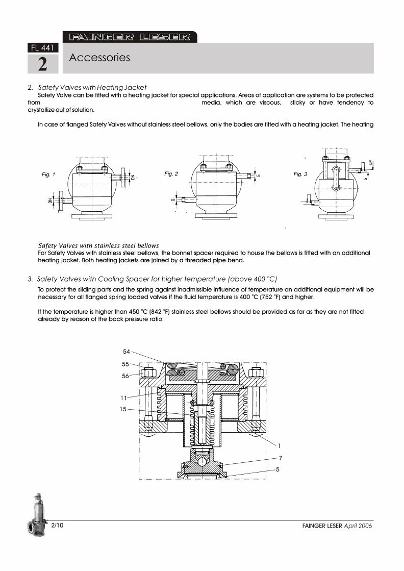
2. Safety Valves with Heating JacketSafety Valve can be fitted with a heating jacket for special applications. Areas of application are systems to be protected
from media, which are viscous, sticky or have tendency to crystallize out of solution.
In case of flanged Safety Valves without stainless steel bellows, only the bodies are fitted with a heating jacket. The heating
Safety Valves with stainless steel bellowsFor Safety Valves with stainless steel bellows, the bonnet spacer required to house the bellows is fitted with an additionalheating jacket. Both heating jackets are joined by a threaded pipe bend.
To protect the sliding parts and the spring against inadmissible influence of temperature an additional equipment will beo onecessary for all flanged spring loaded valves if the fluid temperature is 400 C (752 F) and higher.
o oIf the temperature is higher than 450 C (842 F) stainless steel bellows should be provided as far as they are not fittedalready by reason of the back pressure ratio.
Accessories
o3. Safety Valves with Cooling Spacer for higher temperature (above 400 C)
2/10
FL 441
2
54
55
56
11
15
1
7
5
FAINGER LESER April 2006
Accessories
2/11
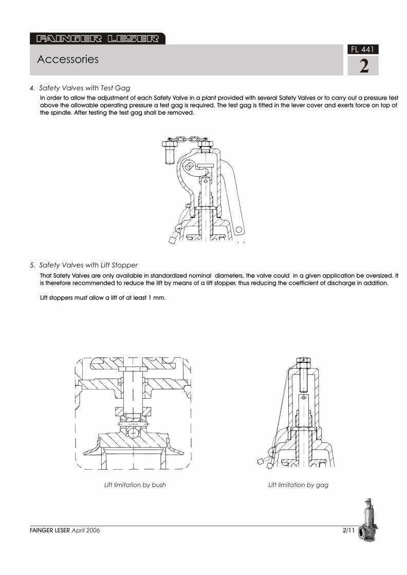
4. Safety Valves with Test Gag
5. Safety Valves with Lift Stopper
In order to allow the adjustment of each Safety Valve in a plant provided with several Safety Valves or to carry out a pressure testabove the allowable operating pressure a test gag is required. The test gag is fitted in the lever cover and exerts force on top ofthe spindle. After testing the test gag shall be removed.
That Safety Valves are only available in standardized nominal diameters, the valve could in a given application be oversized. Itis therefore recommended to reduce the lift by means of a lift stopper, thus reducing the coefficient of discharge in addition.
Lift stoppers must allow a lift of at least 1 mm.
FL 441
2
Lift limitation by bush Lift limitation by gag
FAINGER LESER April 2006

Instructions for the Treatment and Installation ofPressure Relief Valves.
1. General NotesPressure Relief Valves are highly quality instruments which should be handled with great care. To ensure the correct performance of a pressure relief valve all parts are made with exact precision. Only this precision ensures the correct functioning of the pressure relief valves. Careless handling of the finished valve in workshops, stores, during transportation or installation could cause leakage or possibly permanent damage (also refer to API Report Guide for inspection of refinery equipment, Chapt. XVI Pressure Relieving Devices" Para 1603082 and 1603083).
The sealing surfaces have been ground and lapped with high precision to ensure the required tightness. Even though the surfaces are extremely hard, the seal can still be damaged. By all means, one must take care to prevent impurities from entering the valve during transportation, installation and operation.
When installing pressure relief valves with threaded connections, use only metal seal washers. Seal materials such as hemp or PTFE tape should not be used as this type of material can break off and enter the valve causing it to leak.
If valves with open bonnets and/or levers are to be painted after despatch from the factory, care must be taken to protect the sliding parts. Otherwise the correct operation of the pressure relief valve may be affected.
2. Transport ProtectionThe inlet and outlet of the pressure relief safety valves are protected during transportation with plastic caps. These caps should only be removed just before installing the valve.
The lifting lever of spring loaded pressure relief valves is secured with a wire to the bonnet. This wire should be removed only after installation. For testing the set pressure or tightness of the pressure relief valve remove also this wire and take care that the lever is not engaged with the spindle cap.
3. Installation/Assembly
3.1 General NotesSpring loaded pressure relief valves should be
installed with the bonnet VERTICALLY UPWARDS.
Furthermore, pressure relief valves should be mounted in such a way that no inadmissible static, dynamic or thermal loads can be transmitted to the valve due to up and downstream pipe work. If necessary, expansion possibilities should be provided. Stresses by incorrect mounting should be avoided.
3.2 Draining of CondensateTo prevent dirt and all kinds of impurities from the pressure relief valve the drainage of discharge pipe
According to rules a drain hole of sufficient size must be incorporated at the lowest point of pipe work. In all
cases the discharge pipe must first slope in a downwards direction and fitted with a suitable size drain hole before any bends are connected (refer to sketch).
Exception:In special cases, for instance on board of ships an optional drain hole may be recommended in the valve body as it may be that pipe work drainage cannot be guaranteed at a lower point than the valve. The standard drain hole which will then be supplied by the factory is 1/4" BSP. But, by all means, the discharge pipe must be drained too. In extreme cases this hole can be drilled outside of our factory provided that special care is taken to ensure that no damage is done to the sealing surfaces.
All drainage pipes that have been connected must be free of restriction and the ends easily seen. Care must be taken when discharging any drainage to prevent injury to personnel. For example on steam connect a suitable steam trap.
Note!When valves are supplied with a drain hole that is not going to be used the plastic plug fitted in the hole must be removed and replaced by a metal plug.
3.3 Mounting BracketsFor pressure relief valves with mounting brackets a fastening possibility for the brackets should be
provided to withstand the forces of reaction when valve blows off. The bracket holes can be drilled on request.
3.4 InsulationIn case any insulation of the pressure relief valve is provided, the bonnet must be kept free to avoid
unacceptable heating up of the spring.
3.5 Inlet Pipe The inlet pipe for pressure relief valves should be as short as possible and should be so arranged, that
when the valve is in its fully open position the pressure drop must not exceed 3% of set pressure, the edging at the inlet pipe should be rounded off or at least be
chamfered.
If the calculation results in a higher than 3% pressure drop of set pressure then the inlet pipe size must be enlarged.
3.6 Discharge Pipes/Back PressureThe discharge piping on vapours and gases should
be installed in an ascending direction, on liquids in an inclined direction.
2/13
FL 441
2
FAINGER LESER April 2006

The discharge pipework of all pressure relief valves
should be so arranged that the back pressure, which
is built up during blow off, does not exceed a max.
15% of set pressure.
In case of higher back pressure, pressure relief valves
with pressure compensating metal bellows
(balanced type) shall be used. In case the back
pressure is >0.15 times set pressure the capacity of
the pressure relief valves must be recalculated.
3.7 Pressure Relief Valves with bellowsPressure relief valves with elastomer bellows (TRD 721)
as well as metal bellows have a vent hole in the
bonnet.
When fitting pressure relief valve with a vent hole care
must be taken to prevent moisture from entering the
bonnet. However, fluid escaping from the vent hole
indicates that the bellows have failed. Repair is
required.
When pressure relief valves with bellows are used with
toxic or inflammable fluids, care must be taken to fit a
suitable vent pipe to provide safe venting. For this
purpose, the vent can be threaded 1/4" BSP female
on request.
4. Mode of Operation/MaintenanceThe working pressure of the plant should be at least 5% below
the blow down pressure of the valve to enable a correct
reseat. When a slight leakage occurs, due to deposits
between the sealing surfaces, surfaces can be cleaned by
operating the lifting lever causing the valve to blow off.
The valve should be closed by sudden release of the lever. If
this procedure does not stop the leakage, the valve seals are
probably damaged. Repairs should be carried out at our
It is recommended and in Germany required by Rules to lift manually the valve lifting lever from time to time in order to prevent accumulation of deposits that will affect valve operation. For steam generators, the following requirements are established in the German Technical Rules for Steam Boilers TRD 601, edition 6.83, Section 6.
"Testing of pressure relief valves is required for plants operating with demineralized water and for hot water generators at intervals of at least 6 months, with the exception of power plants. For other steam generators, the test interval should not exceed 4 weeks".
It is important to ensure that the lifting lever does not engage the spindle cap after the lift operation. The lever must be deflected towards the center line of the bonnet until the lifting fork is disengaged.
For pressure relief valves with open bonnet, a drain groove is provided in the guide flange. Whilst blowing, condensate escaping through the clearance between guide disc and spindle is drained through this groove.
According to DIN specification 4754, Oct. 74 Edition "Explanations", Para 4.4 pressure relief valves represent the last step in the line of protection for the vessel, and they should be able to prevent excess pressure when all other automatic or pilot operated checking instruments have failed. To guarantee this function pressure relief valves require, like all other technical equipment, regular service. How often a valve must be checked, depends on the actual operating conditions, so that no general indications can be given. Usually pressure relief valves operating in a corrosive atmosphere or on laden fluids require service more often than valves operating clean conditions. This also applies if the pressure relief valve operates frequently causing a higher wear out to the seat and disc.
Special consideration is required if conditions such as vibration (to be avoided, if possible) pressure pulsation and/or
2/14
Instructions for the Treatment and Installation ofPressure Relief Valves.
FL 441
2
Add, drain pipe in case ofprepared drain hole
FAINGER LESER April 2006

1. Loosen the existing lead seal.
2. Press the lever (43) towards the middle until it reaches
the stop so that the lifting fork(44) no longer holds the
spindle cap (46).
3. Loosen and remove the lever cover (41).
4. Loosen the spindle cap (46) from the spindle (12),
remove the securing ring (91) and the pin (74).
5. Loosen the lock nut (19) of the adjusting screw (18).
6. Turn the adjusting screw (18) anticlockwise to remove
the all spring tension.
7. Remove the hex. nuts (56) from the flange of the
bonnet (9).
8. Lift off the bonnet (9).
9. Remove the upper spring plate (16).
10. Lift of the spring (54) and remove lower spring plate
(16) and split rings (14).
11. Remove spindle (12) with guide (8) and disc (7).
12. Carefully clean seat (5) and disc (7), and if required
body internals.
13. Refit spindle (12) with guide (8) and disc (7).
14. Fit the split rings (14) into spindle groove and retain
with the securing ring (59); slip on lower spring plate
(16) to locate on split rings (14).
15. Replace spring (54).
16. Slip on the upper spring plate (16) onto the spindle
(12).
17. Align adjusting screw (18), and bonnet (9), over the
spindle (12) and refit.
18. Fit and tighten the hex. nuts (56).
19. Load the spring (54) to obtain the required set
pressure. Clockwise rotation of adjusting screw (18)
increases pressure. Anticlockwise rotation of adjusting
screw (18) reduces pressure.
20. Tighten the lock nut (19) onto the adjusting screw (18).
21. Refit and secure spindle cap (46) by pin (74) and
securing (91).
22. Screw-on the lever cover (41).
23. Pull the lever (43) towards the middle so that the lifting
fork (44) is pushed under the spindle cap (46).
24. Test spindle will lift correctly by pulling lever.
These instructions are applicable for Relief Valves,
2/15
Dismantling and Assembly InstructionsFor Valve Type FL 441, FL 459 & FL 549 Series
FL 441
2
44
41
43
18
19
FAINGER LESER April 2006
During all work the spindle has to be secured against twisting in order to prevent damage to the sealing surfaces.
CAUTION
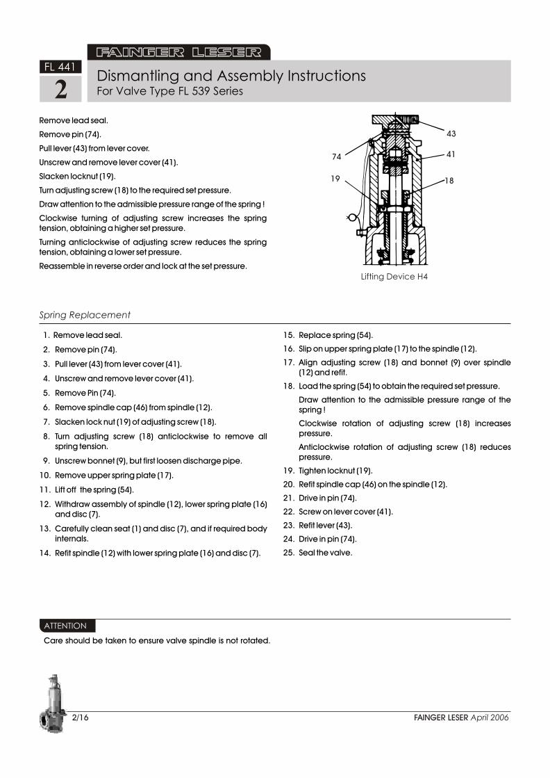
Remove lead seal.
Remove pin (74).
Pull lever (43) from lever cover.
Unscrew and remove lever cover (41).
Slacken locknut (19).
Turn adjusting screw (18) to the required set pressure.
Draw attention to the admissible pressure range of the spring !
Clockwise turning of adjusting screw increases the spring tension, obtaining a higher set pressure.
Turning anticlockwise of adjusting screw reduces the spring tension, obtaining a lower set pressure.
Reassemble in reverse order and lock at the set pressure.
2/16
1. Remove lead seal.
2. Remove pin (74).
3. Pull lever (43) from lever cover (41).
4. Unscrew and remove lever cover (41).
5. Remove Pin (74).
6. Remove spindle cap (46) from spindle (12).
7. Slacken lock nut (19) of adjusting screw (18).
8. Turn adjusting screw (18) anticlockwise to remove all spring tension.
9. Unscrew bonnet (9), but first loosen discharge pipe.
10. Remove upper spring plate (17).
11. Lift off the spring (54).
12. Withdraw assembly of spindle (12), lower spring plate (16) and disc (7).
13. Carefully clean seat (1) and disc (7), and if required body internals.
14. Refit spindle (12) with lower spring plate (16) and disc (7).
Care should be taken to ensure valve spindle is not rotated.
74
19
43
41
18
Lifting Device H4
FAINGER LESER April 2006
ATTENTION
15. Replace spring (54).
16. Slip on upper spring plate (17) to the spindle (12).
17. Align adjusting screw (18) and bonnet (9) over spindle (12) and refit.
18. Load the spring (54) to obtain the required set pressure.
Draw attention to the admissible pressure range of the spring !
Clockwise rotation of adjusting screw (18) increases pressure.
Anticlockwise rotation of adjusting screw (18) reduces pressure.
19. Tighten locknut (19).
20. Refit spindle cap (46) on the spindle (12).
21. Drive in pin (74).
22. Screw on lever cover (41).
23. Refit lever (43).
24. Drive in pin (74).
25. Seal the valve.
Spring Replacement
Dismantling and Assembly InstructionsFor Valve Type FL 539 Series
FL 441
2