method of revolution (rotation)
TRANSCRIPT
7 Method of Revolution (Rotation)
In solving many of our problems previously we have implicitly assumed that the viewer changes position in order to see different possible projections of a geometric figure or element. The geometric figure or element be it a point, line, plane, solid or what have you is fixed in position relative to the frame of reference made up of two orthogonal views, typically top and front projection planes. Problems involving true lengths and point views of lines, edge views and true shapes of planes, angles between two planes and the angle that a line makes with a plane can be solved much quicker and much more easily if we allow the geometric figure to change its position relative to a given pair of orthogonal views.
This change in position is accomplished by revolving, or rotating, the geometric figure around a specific axis in a specific direction. So we need: i) an axis of rotation; ii) a center of rotation; and iii) a path of rotation. That is, we define a circle (or part of a circular plane), of rotation with specific radius.
7.1 BASICS OF REVOLUTION
7.1.1 Revolving a point about a line axis
When a point is revolved about a given line axis the point is located at a specific distance from the axis. In Figure 7-1 we see a point P located at radius R rotated about axis AX creating a circular path of rotation.
There are a couple of things to note:
1) The axis of rotation is perpendicular to the plane of rotation or the viewing plane (Axis is seen in true length in one of the orthogonal views usually in elevation).

198
7-1 Revolving a point about a line
2) The path of rotation is a circle in which the center is seen as a point (Axis of rotation
is seen in point view and plane of rotation seen in edge view in the appropriate projection planes).
The above is true of any geometric figure as every figure consists of points. Figure 7-2 illustrates the construction.
Construction 7-1 Revolving a point about a line
We assume that we given the axis in true length. We are required to revolve a given point P through a given angle.
7-2
Revolving a point about a line
R
Observers line of sight
path taken by P
circle (plane) of rotation
axis of rotation
Pnew
P
center of rotation
circular path of rotation
c1
radius
TL of axis of rotation
EV of plane of rotation
P
Pnew
PV of axis
Pnew
P

199
There are three main steps.
1. We note that in plan, the axis of rotation is in point view and that the center of rotation coincides with the axis. We draw a circular arc with radius equal to the distance between the center and the point P, in plan, through the given angle to its new position, Pnew.
2. In elevation, we draw a line perpendicular to the axis passing through the point P. This line represents the edge view of the plane of rotation.
Project down from Pnew to the elevation onto the edge view of the plane of rotation.
In many descriptive geometry problems, the axis may not be given in true length in which case a new view must be drawn in which the axis is seen in true length. This is illustrated in Figure 7-3.
7-3 Revolving a point about an oblique line
7.1.2 Revolving a line about a line axis
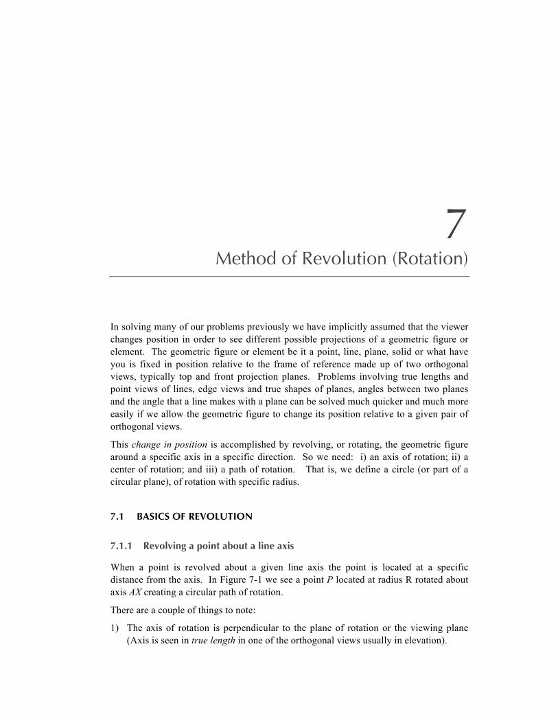
When revolving a line about an axis, if one end of the line is on the axis and the rotation goes through 360°, a cone of revolution is generated. See Figure 7-4.
l
l
TL of l
121
T
F
T
Pnew
P
P
P
P
Pnew
Pnew
Pnew
200
7-4 Revolving a line about a line
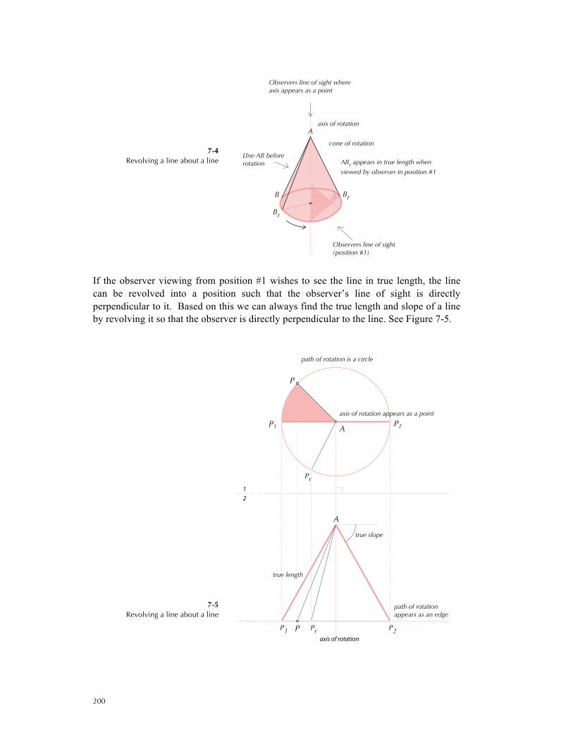
If the observer viewing from position #1 wishes to see the line in true length, the line can be revolved into a position such that the observer’s line of sight is directly perpendicular to it. Based on this we can always find the true length and slope of a line by revolving it so that the observer is directly perpendicular to the line. See Figure 7-5.
7-5
Revolving a line about a line
LIne AB beforerotation
cone of rotation
axis of rotation
ABr appears in true length when
viewed by observer in position #1
Observers line of sight(position #1)
Observers line of sight whereaxis appears as a point
Br
Br
B
A
true length
axis of rotation appears as a point
axis of rotation
path of rotationappears as an edge
path of rotation is a circle
21
true slope
PrPP1
P1
P2
P2A
A
P
Pr

201
Figure 7-5 illustrates a construction to determine the true length and slope of a line by revolving the line. For any line, choose in a view, say 1, an axis of rotation that passes through an end-point of the line. Then:
1. Rotate the other end-point point till the radius is parallel to the folding line.
2. Project the new point to the other view, 2. In this view, the line is seen in true length and, if the view is an elevation, the slope to the horizontal is its true slope.
Four variations are shown in Figure 7-6. However,
True slope can only be found if true length is seen in elevation
7-6 Finding the true length and slope by revolution
Other variations exist when the axis of rotation is on the line (see Figure 7-7) or off the line (Figure 7-8).
TL
plane of rotation
axis of rotation
PV of axis
true slope
TL axis of rotation
plane of rotation
true slope
PV of axis
TL
plane of rotation
axis of rotation
PV of axis
TL
axis of rotation
plane of rotation
PV of axis
202
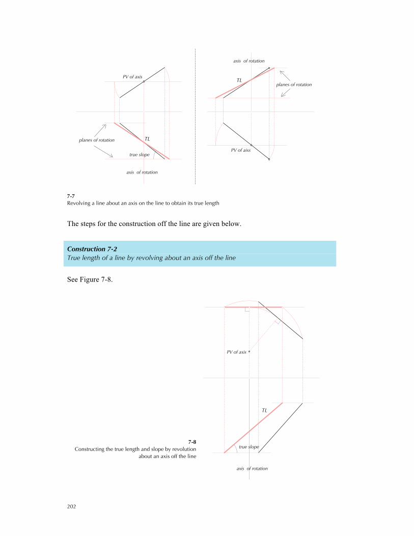
7-7 Revolving a line about an axis on the line to obtain its true length
The steps for the construction off the line are given below.
Construction 7-2 True length of a line by revolving about an axis off the line
See Figure 7-8.
7-8 Constructing the true length and slope by revolution
about an axis off the line
TLplanes of rotation
axis of rotation
PV of axis
true slope
TL
axis of rotation
planes of rotation
PV of aixs
TL
axis of rotation
PV of axis
true slope

203
The steps are:
1. In top view, rotate the foot of the perpendicular to the line from the point view of the axis until the radius is perpendicular to the folding line.
2. In this view construct a parallel to the folding line passing through the rotated point.
3. Rotate the end points of the line to this parallel line
4. Project the rotated points into the other view to intersect lines drawn parallel to the folding line passing through the end points of the line. These lines represent an edge view of the plane of rotations.
5. The line joining the intersection points gives the true length of the original line
7.1.3 Revolving a plane about a line axis
One can apply the method of revolution to planes to solve certain descriptive geometry problems. For example, a plane can be revolved about a line so that it is perpendicular to the viewer’s line of sight showing the plane in true shape. Figure 7-9 illustrates this with the axis of rotation lying on the plane.
7-9 Revolving a plane about a line
lying in the plane
This figure gives rise to the following construction.
Construction 7-3 True shape of a plane using the method of revolution
There are five steps assuming that we are given the top and front view of a plane.
1. In the front view, draw a horizontal line. This line will be used as the axis of rotation.
2. In top view, this line will be seen in true length, and can be used to construct the edge view of the plane with the line seen in point view.
3. In view #3, rotate the edge view about the axis so that the rotated line is parallel to the folding line.
4. Project the rotated points to the top view to intersect the path of rotations, which are perpendicular to the true length of the axis.
5. Connect the project points to give the true shape of the plane.
Observer'sline of sight
Plane ABCbefore rotation
True shape of ABC seenby observer after rotation
Cr
B
Br (revolved)
C
A

204
See Figure 7-10. Note that both A and C are revolved through the same angular rotation about the axis through B.
7-10 Determining the true shape of a plane by method of rotation
The axis of rotation could also lie outside the plane. See Figure 7-11.
7-11 Rotating a plane about a line outside the plane
Edge view of ABC
True shape of ABC
Axis in TL
Edge view of paths of rotation
PV of axis
Horizontalline as axis
1 3
2
1
Anew
Cnew
Cnew
Anew
C
B
A
A
B
C
C
A B
Initial positionof plane ABC
Plane ABC revolved
Observers line of sight in whichthe true shape of ABC is seen
TL axis of rotation
Br
A
B
C
Ar
Cr

205
The construction follows steps similar to Construction 7-3 using Construction 7-2. It is illustrated below in Figure 7-12. Again it is important to note that A, B and C are revolved through the same angular rotation.
7-12 Determining the true shape of a plane by the method of revolution based on a rotation about an axis outside the plane
7.1.4 Counter-revolution – A worked example
Consider the quadrilateral ABCD shown in Figure 7-13. We are required to remove a square from it with sides, say 1.5", with center located 1" below B, 13/8" away from A with two sides of the square horizontal. We want to construct the top and front views of the resulting shape.
There are two parts to this problem.
The first part is to construct the square in the same plane as ABCD (How do we know that ABCD is planar?).
The second part requires removing the square from the ABCD to give us the required shape and views.
The first part requires determining ABCD in true shape. We construct the edge view of ABCD using a horizontal line in elevation. As the center of the square O is located 1" below B we use a horizontal line 1” below B to construct the edge view. This will enable us to locate O. See Figure 7-13.
Axis in TLTrue shape of ABC
HL in TL
Axis seen as a pointoutside the plane ABC
Horizontal line HL
1 3
2
1
Bnew
Anew
Cnew
C
A
B
A
B
C
C
AB
206
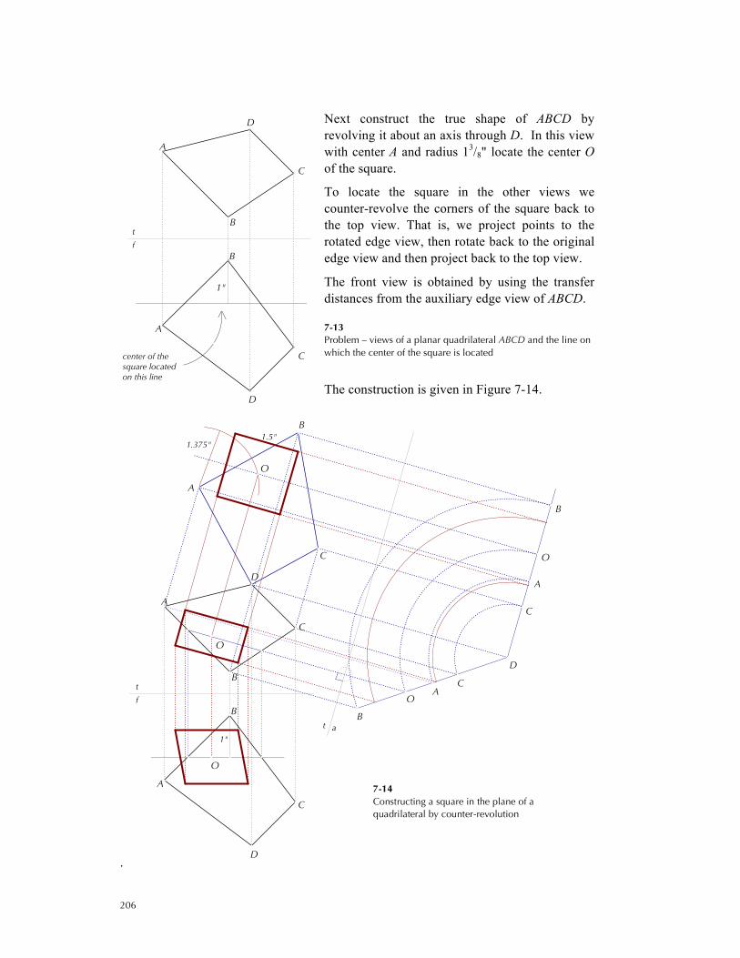
Next construct the true shape of ABCD by revolving it about an axis through D. In this view with center A and radius 13/8" locate the center O of the square.
To locate the square in the other views we counter-revolve the corners of the square back to the top view. That is, we project points to the rotated edge view, then rotate back to the original edge view and then project back to the top view.
The front view is obtained by using the transfer distances from the auxiliary edge view of ABCD.
7-13 Problem – views of a planar quadrilateral ABCD and the line on which the center of the square is located
The construction is given in Figure 7-14.
.
1"
center of thesquare locatedon this line
f
t
C
B
A
D
B
A
D
C
1"
1.5"1.375"
at
f
t
O
O
O
B
C
A
B
O
A
C
O
CA
B
DB
A
C
D
A
D
C
B
7-14 Constructing a square in the plane of a quadrilateral by counter-revolution
207
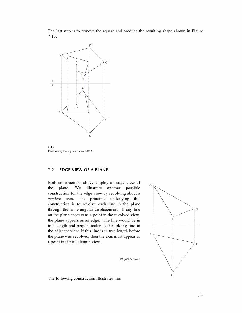
The last step is to remove the square and produce the resulting shape shown in Figure 7-15.
7-15 Removing the square from ABCD
7.2 EDGE VIEW OF A PLANE
Both constructions above employ an edge view of the plane. We illustrate another possible construction for the edge view by revolving about a vertical axis. The principle underlying this construction is to revolve each line in the plane through the same angular displacement. If any line on the plane appears as a point in the revolved view, the plane appears as an edge. The line would be in true length and perpendicular to the folding line in the adjacent view. If this line is in true length before the plane was revolved, then the axis must appear as a point in the true length view.
(Right) A plane
The following construction illustrates this.
f
t
O
O
B
A
C
D
A
D
C
B
f
t
A
B
C
A
B
C
208
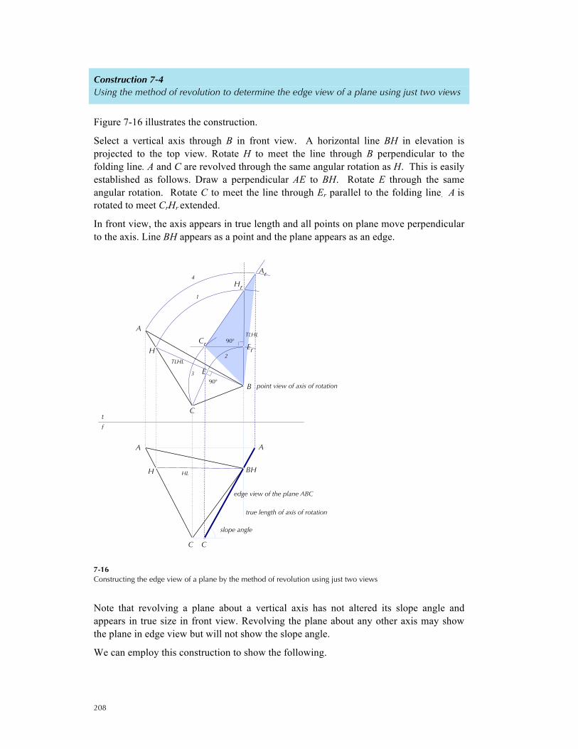
Construction 7-4 Using the method of revolution to determine the edge view of a plane using just two views
Figure 7-16 illustrates the construction.
Select a vertical axis through B in front view. A horizontal line BH in elevation is projected to the top view. Rotate H to meet the line through B perpendicular to the folding line. A and C are revolved through the same angular rotation as H. This is easily established as follows. Draw a perpendicular AE to BH. Rotate E through the same angular rotation. Rotate C to meet the line through Er parallel to the folding line. A is rotated to meet CrHr extended.
In front view, the axis appears in true length and all points on plane move perpendicular to the axis. Line BH appears as a point and the plane appears as an edge.
7-16 Constructing the edge view of a plane by the method of revolution using just two views
Note that revolving a plane about a vertical axis has not altered its slope angle and appears in true size in front view. Revolving the plane about any other axis may show the plane in edge view but will not show the slope angle.
We can employ this construction to show the following.
1
4
2
3
TLHL
TLHL
HL
slope angle
90°
90°
f
t
edge view of the plane ABC
point view of axis of rotation
true length of axis of rotation
Er
E
A
C
Ar
Cr
Hr
H
H
A
B
C
A
BH
C

209
Construction 7-5 Using the method of revolution to determine the true shape of a plane using just two views
The construction is shown in Figure 7-17 for the same plane shown in Figure 7-16. There are two parts to the construction.
The first part employs the method of revolution in Figure 7-16 to construct an edge view of the plane.
For the second part, from the edge view, we again use the method of revolution to produce the true shape. Here CI in front view is the point view of the axis of rotation. AI and B are rotated to points AIr and BIr in the front view and projected onto the top view as shown in Figure 7-17 to get the true shape of ABC.
7-17 True shape of a plane by the method of rotation using just two views
7.3 DIHEDRAL ANGLE BY REVOLUTION
To determine the dihedral angle between two planes we need a cutting plane, which is perpendicular to the line of intersection between the two planes. This cutting plane cuts a plane section between the planes, the true shape of which contains the dihedral angle.
1
4
2
3
TLHL
TLHL
HL
true shape of ABC90°
90°
f
t
point view of second axis of rotation
true length of the second axis of rotation
B2
A2
A1rB1r
Er
E
A1
C1
Ar
Cr
Hr
H
H
A
B
C
A
BH
C

210
By revolving the plane section so that it is perpendicular to the viewer’s line of sight one sees the true dihedral angle. The construction is described below.
7-18 Obtaining the dihedral angle between two planes
Construction 7-6 Dihedral angle between planes by the method of revolution
1. Obtain the true length of the line of intersection by constructing an auxiliary view a.
2. In this auxiliary view construct the edge view of any cutting perpendicular to the line of intersection and project the points back to the top view.
3. Choose for an axis a point at which the edge view of the cutting appears in view a, say P3. Rotate the plane section so that it is parallel to the folding line t | a. This determines the points P1r and P2r.
4. Project P1r and P2r to the top view to locate P1n
and P2n, which lie on paths path perpendicular to the true length of the axis of revolution.
5. The dihedral angle is measured between the two lines joining P3, P1n and P2n.
The construction is given Figure 7-19. Figure 7-20 illustrates a different point view for the axis of rotation while still giving the same result.
Line of intersection
Line of intersection
f
t
B
D
A
C
B
C
D
A

211
7-19 Dihedral angle between planes by the method of revolution
7-20 Alternate choice for the axis of rotation in 7-19
PV axis of rotation
TL axis of rotation
Edge view of cutting plane
t
a
TL Line of intersection
True dihedral angle between planes
Line of intersection
f
t
P2
P1r
P2r
P1
P3
P3
C
D
A
B
B
D
A
C
B
C
D
A
P1
True dihedral angle between planes
Line of intersection (TL)
Line of intersectiona
t
f
t
TL of axis of rotation
PV of axis of rotation
Edge view of cutting plane
P3n
P2n
P3r
P2r
P2
P2
P1
P1
P3
P3
A
B
C
D
B
D
A
C
B
C
D
A
212
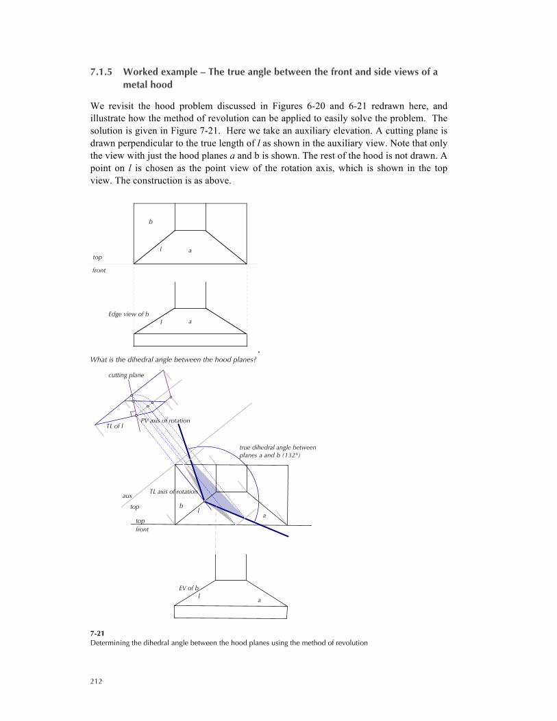
7.1.5 Worked example – The true angle between the front and side views of a metal hood
We revisit the hood problem discussed in Figures 6-20 and 6-21 redrawn here, and illustrate how the method of revolution can be applied to easily solve the problem. The solution is given in Figure 7-21. Here we take an auxiliary elevation. A cutting plane is drawn perpendicular to the true length of l as shown in the auxiliary view. Note that only the view with just the hood planes a and b is shown. The rest of the hood is not drawn. A point on l is chosen as the point view of the rotation axis, which is shown in the top view. The construction is as above.
. What is the dihedral angle between the hood planes?
7-21 Determining the dihedral angle between the hood planes using the method of revolution
l
l
front
top
Edge view of ba
a
b
l
l
TL of l
aux
top
PV axis of rotation
TL axis of rotation
true dihedral angle betweenplanes a and b (132°)
cutting plane
front
top
EV of b
a
a
b
213
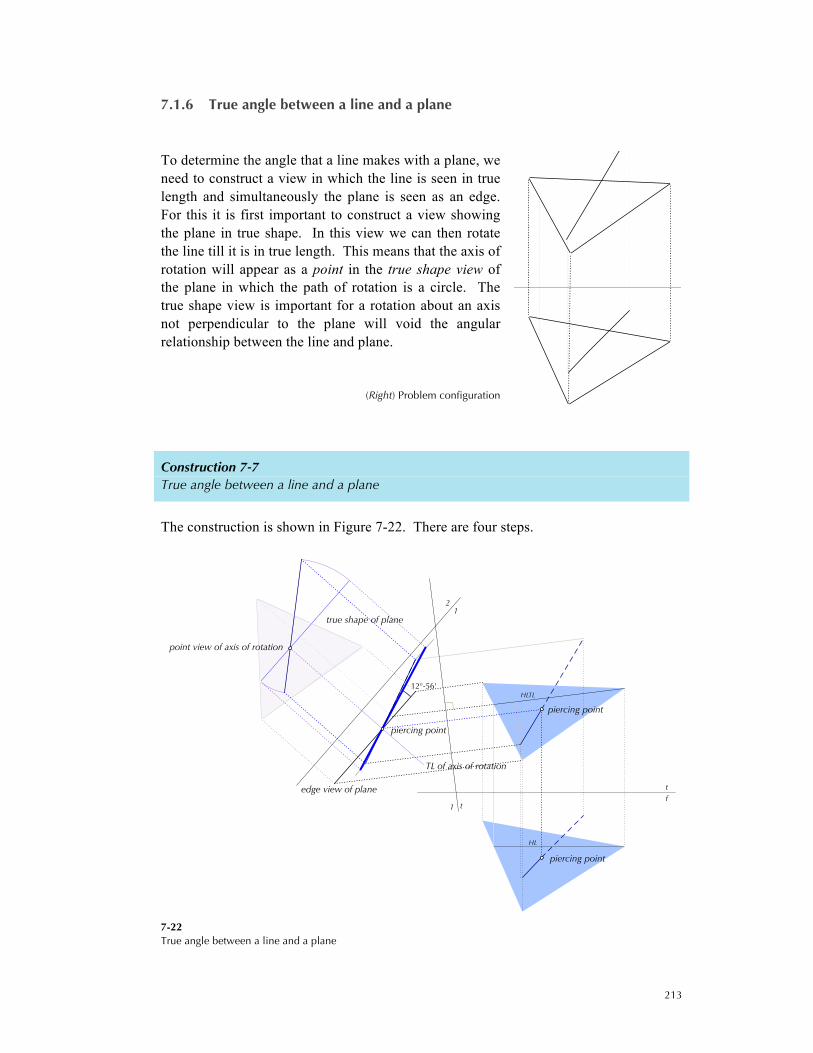
7.1.6 True angle between a line and a plane
To determine the angle that a line makes with a plane, we need to construct a view in which the line is seen in true length and simultaneously the plane is seen as an edge. For this it is first important to construct a view showing the plane in true shape. In this view we can then rotate the line till it is in true length. This means that the axis of rotation will appear as a point in the true shape view of the plane in which the path of rotation is a circle. The true shape view is important for a rotation about an axis not perpendicular to the plane will void the angular relationship between the line and plane.
(Right) Problem configuration
Construction 7-7 True angle between a line and a plane
The construction is shown in Figure 7-22. There are four steps.
7-22 True angle between a line and a plane
tf
HL
HLTL
edge view of plane
TL of axis of rotation
true shape of plane
piercing point
point view of axis of rotation
12°-56'
21
t
1 tf
piercing point
piercing point

214
1. As before construct an edge view of the plane using an auxiliary view. In this view, the line intersects the edge view at the piercing point.
2. Project the edge view to produce the true shape of the plane in view #2. Project the line and the piercing point in this view.
3. Using the piercing point as the point view of the axis of rotation, rotate one or both end points of the line.
4. Project back to view #1 from which the angle made by the TL of the line with the edge view gives the true angle.
We can do the entire construction in two views using just rotations. See Figure 7-23.
7-23 True angle between a line and a plane in two views using the method of revolution
HL
HLTL
edge view of planetrue length of line
true shape of planeshown in outline
piercing point
12°-56'
tf
piercing point
piercing point
215
7.4 CONE-LOCUS (HARDER MATERIAL)
7.1.7 Locating a line making a constant angle with an intersecting line
There are a number of problems in descriptive geometry that are related to this problem. To solve problems of this kind we introduce a concept known as the cone-locus of a line. A locus is a path of a moving point that satisfies some stipulated condition. For example, the locus of a moving point equidistant to two points is the plane that bisects and is perpendicular to the line joining the two points. The locus of a point equidistant to three non-collinear points is a straight line. It is the common line of intersection of three planes each bisecting and is perpendicular to the line joining two of the points.) The locus of a point equidistant to four non-coplanar points is a single point. And so on. Here we are interested in the locus of a line that intersects and makes a constant angle with a given line.
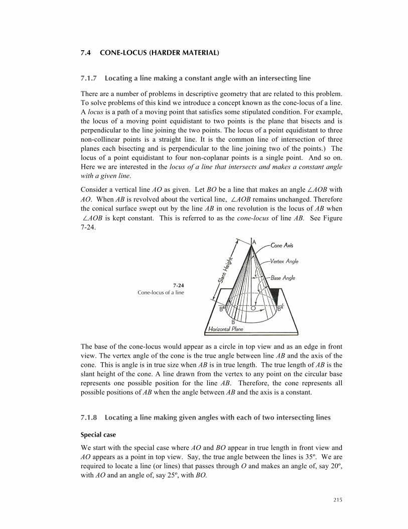
Consider a vertical line AO as given. Let BO be a line that makes an angle ∠AOB with AO. When AB is revolved about the vertical line, ∠AOB remains unchanged. Therefore the conical surface swept out by the line AB in one revolution is the locus of AB when ∠AOB is kept constant. This is referred to as the cone-locus of line AB. See Figure 7-24.
7-24 Cone-locus of a line
The base of the cone-locus would appear as a circle in top view and as an edge in front view. The vertex angle of the cone is the true angle between line AB and the axis of the cone. This is angle is in true size when AB is in true length. The true length of AB is the slant height of the cone. A line drawn from the vertex to any point on the circular base represents one possible position for the line AB. Therefore, the cone represents all possible positions of AB when the angle between AB and the axis is a constant.
7.1.8 Locating a line making given angles with each of two intersecting lines
Special case
We start with the special case where AO and BO appear in true length in front view and AO appears as a point in top view. Say, the true angle between the lines is 35º. We are required to locate a line (or lines) that passes through O and makes an angle of, say 20º, with AO and an angle of, say 25º, with BO.
216
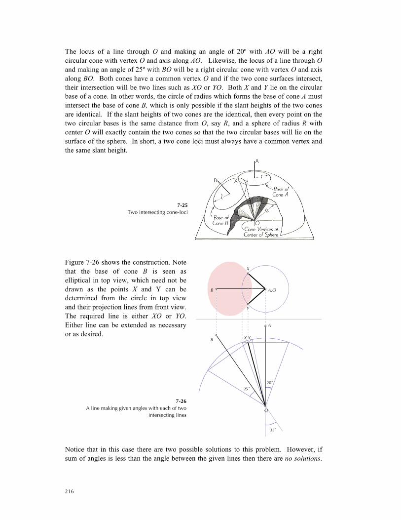
The locus of a line through O and making an angle of 20º with AO will be a right circular cone with vertex O and axis along AO. Likewise, the locus of a line through O and making an angle of 25º with BO will be a right circular cone with vertex O and axis along BO. Both cones have a common vertex O and if the two cone surfaces intersect, their intersection will be two lines such as XO or YO. Both X and Y lie on the circular base of a cone. In other words, the circle of radius which forms the base of cone A must intersect the base of cone B, which is only possible if the slant heights of the two cones are identical. If the slant heights of two cones are the identical, then every point on the two circular bases is the same distance from O, say R, and a sphere of radius R with center O will exactly contain the two cones so that the two circular bases will lie on the surface of the sphere. In short, a two cone loci must always have a common vertex and the same slant height.
7-25 Two intersecting cone-loci
Figure 7-26 shows the construction. Note that the base of cone B is seen as elliptical in top view, which need not be drawn as the points X and Y can be determined from the circle in top view and their projection lines from front view. The required line is either XO or YO. Either line can be extended as necessary or as desired.
7-26 A line making given angles with each of two
intersecting lines
Notice that in this case there are two possible solutions to this problem. However, if sum of angles is less than the angle between the given lines then there are no solutions.
35°
25 °20°
Y
X
X,Y
B A,O
A
O
B
217
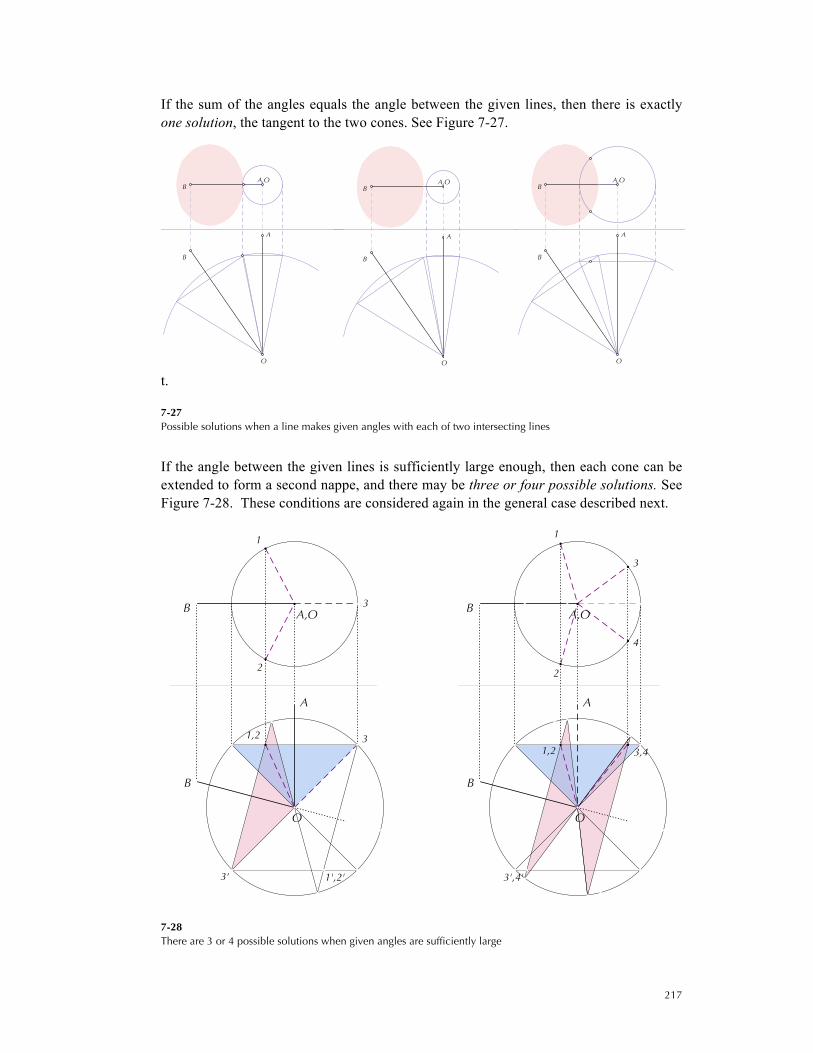
If the sum of the angles equals the angle between the given lines, then there is exactly one solution, the tangent to the two cones. See Figure 7-27.
t.
7-27 Possible solutions when a line makes given angles with each of two intersecting lines
If the angle between the given lines is sufficiently large enough, then each cone can be extended to form a second nappe, and there may be three or four possible solutions. See Figure 7-28. These conditions are considered again in the general case described next.
7-28 There are 3 or 4 possible solutions when given angles are sufficiently large
BA,O A,O
BA,O
B
A
O
B
A
O
B
A
O
B
4
3
2
1
3',4'
1,2 3,4
B
2
1
3
B
1',2'
1,2
3'
3
B A,O A,OB
A
O
A
O
218
General case
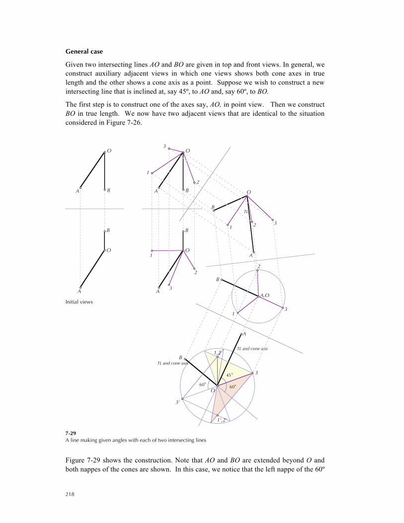
Given two intersecting lines AO and BO are given in top and front views. In general, we construct auxiliary adjacent views in which one views shows both cone axes in true length and the other shows a cone axis as a point. Suppose we wish to construct a new intersecting line that is inclined at, say 45º, to AO and, say 60º, to BO.
The first step is to construct one of the axes say, AO, in point view. Then we construct BO in true length. We now have two adjacent views that are identical to the situation considered in Figure 7-26.
Initial views
7-29 A line making given angles with each of two intersecting lines
Figure 7-29 shows the construction. Note that AO and BO are extended beyond O and both nappes of the cones are shown. In this case, we notice that the left nappe of the 60º
O
BA
O
A
B
TL
TL and cone axis
TL and cone axis
60°60°
45°
3'
3
2
1
1
3
2
213
2
13
3
1',2'
1,2B
O
A
A,O
B
O
B
A
O
BA
O
A
B

219
cone intersects the upper nappe of the 45º cone providing two solutions 1O and 2O. The right nappe of the 60º cone is tangent to the upper nappe of the 45º cone providing the third solution 3O. The lines 1'O, 2'O and 3'O are not additional solutions, but, simply, alternative solutions, extensions of 1O, 2O and 3O respectively.
Figure 7-30 illustrates a situation where four possible solutions exist. Here we locate a line that makes angle of 45º and 75º to each of the two intersecting lines AO and BO.
7-30 A line making given angles with each of two intersecting lines (Four solutions)
Note that, in general, there may be zero up to four possible solutions of locating a line making given angle with each of two intersecting lines.
TL
TL and cone axis
TL and cone axis
75°45°
1
3
4
2
3
4
2
1
3 2 41
2
1
4
3
1,2
1',2'
3',4'
3,4
B
O
A
A,O
B
O
B
A
O
BA
O
A
B

220
7.1.9 Locating a line making given angles with each of two skew lines
Such problems occur in construction work where it is necessary to connect two skew pipes with a third pipe that are available only at certain stock angles. Two skew lines do not intersect; there share no common point. However, the solution for skew lines and the solution for intersecting lines parallel to the skew lines produce parallel results. That is, we can obtain the direction of the solution if we can obtain the solution for the two intersecting lines each parallel to a skew line.
Let the skew lines be AB and CD. Let the line be located so that it intersects AB at 45° and CD at 60°.
The construction is shown in Figure 7-31.
As before we construct two views of the skew lines one showing a line (AB) in point view and the other showing both lines in true length.
We make a copy of the last two views so constructed. That is, a new folding line, all the skew lines drawn parallel to the original but with C'D' is coincident with the point view of A'B'. We now have intersecting lines each of which parallel to the original.
By following the previous construction shown in Figure 7-29, it is clear that 1'O', 2'O' and 3'O' make the required angles with the intersecting lines A'B' and C'D'.
These lines establish the direction for the required lines. By drawing lines parallel to lines 1'O' and 2'O' view we locate lines 1X and 2Y in the original views. There is no third solution as the line parallel to 3'O' will never meet CD. Note that we need to locate points 1 and 2 in the second auxiliary view before locating X and Y in the third auxiliary view.
7-31 A line making given angles with each of two skew lines (Two solutions)
TL
TL
TL
TL
TL
parallel lines
parallel lines
45°60°
O
2
1
XY
1
2
X
Y
X
Y1
2
X
Y
2 1
12
3'2'
1'
C'
D'
1',2'3'
C'D'
B'
A'
A',B'
CD
A
B
D
C
A,B
C
D
A
B
C
D
A
B
C
D
A
B
221
In general, for any pair of skew lines, there may be zero, two or four solutions, depending on the stipulated angles that a line has to make with each of the skew lines.
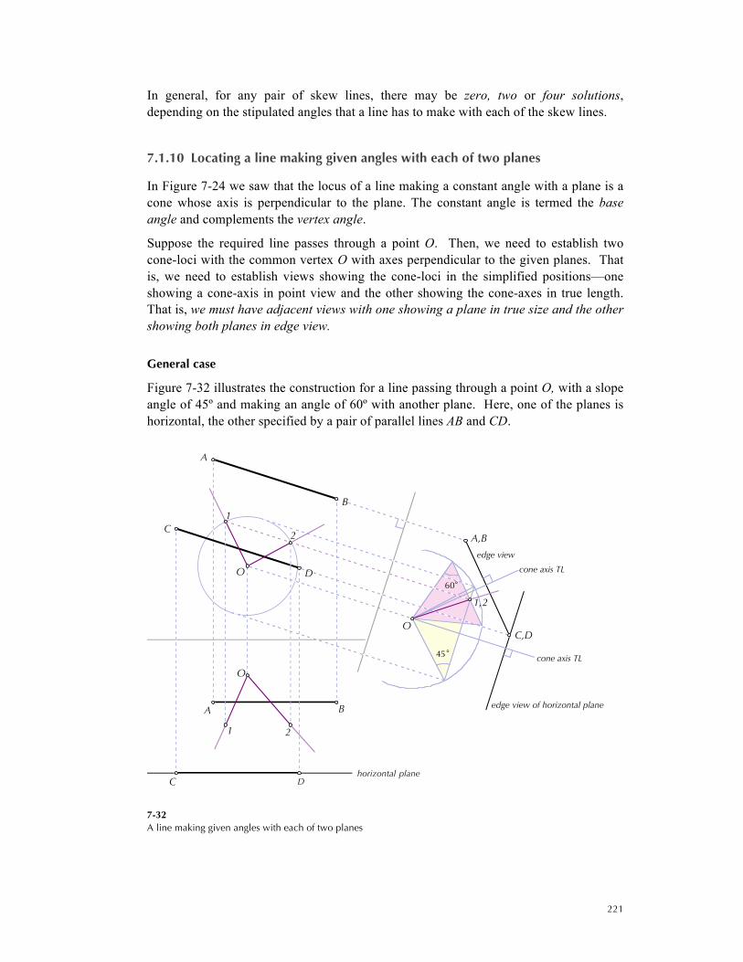
7.1.10 Locating a line making given angles with each of two planes
In Figure 7-24 we saw that the locus of a line making a constant angle with a plane is a cone whose axis is perpendicular to the plane. The constant angle is termed the base angle and complements the vertex angle.
Suppose the required line passes through a point O. Then, we need to establish two cone-loci with the common vertex O with axes perpendicular to the given planes. That is, we need to establish views showing the cone-loci in the simplified positions—one showing a cone-axis in point view and the other showing the cone-axes in true length. That is, we must have adjacent views with one showing a plane in true size and the other showing both planes in edge view.
General case
Figure 7-32 illustrates the construction for a line passing through a point O, with a slope angle of 45º and making an angle of 60º with another plane. Here, one of the planes is horizontal, the other specified by a pair of parallel lines AB and CD.
7-32 A line making given angles with each of two planes
horizontal plane
edge view of horizontal plane
edge view
cone axis TL
cone axis TL
60°
45°
1 2
2
1
1,2
OC,D
A,B
B
D
A
O
A
C
C
B
DO
222
Since in top view the horizontal plane is seen in true size we can locate the point view of a cone axis through O. An auxiliary view shows both planes in edge view. A sphere of an appropriate radius is constructed; the radius corresponds to the slant height of the two cone-loci. In this problem situation, the given angles are base angles not vertex angles and the cones must appropriately constructed. In the example shown, a second nappe is not constructed, as it would yield no additional solutions. In general, such problems may have up to four solutions.
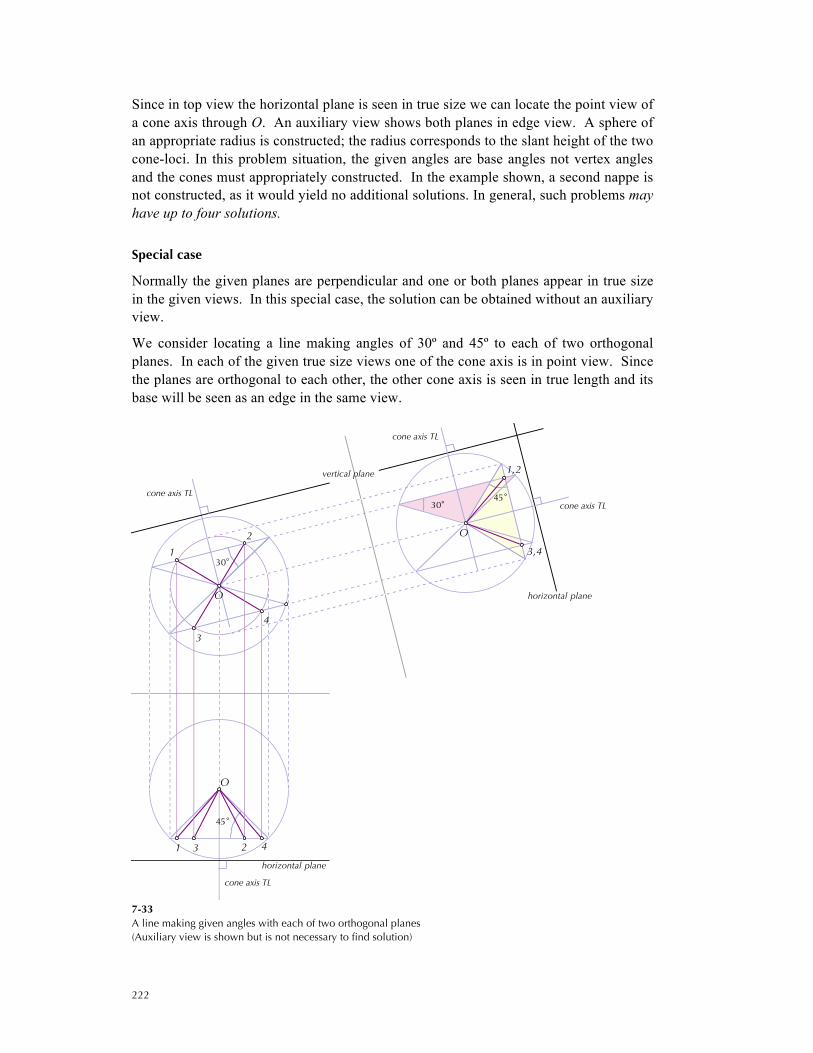
Special case
Normally the given planes are perpendicular and one or both planes appear in true size in the given views. In this special case, the solution can be obtained without an auxiliary view.
We consider locating a line making angles of 30º and 45º to each of two orthogonal planes. In each of the given true size views one of the cone axis is in point view. Since the planes are orthogonal to each other, the other cone axis is seen in true length and its base will be seen as an edge in the same view.
7-33 A line making given angles with each of two orthogonal planes (Auxiliary view is shown but is not necessary to find solution)
cone axis TL
cone axis TL
horizontal plane
cone axis TL
vertical plane
horizontal plane
cone axis TL
30° 45°
30°
45°
3,4
1,2
O
1 3 2 4
4
3
1
2
O
O
223
It is possible to solve the problem by constructing an auxiliary view in which both planes are seen in edge view. However, this additional view is not necessary. See Figure 7-33.
In front view the axis of the 45º cone will appear vertical and in true length. Consequently, we may assume a sphere of an appropriate radius and establish the cone within this sphere. In top view the base of the cone will appear as a circle. In top view the base of the cone is perpendicular to the given vertical plane and in true length. We construct a view of the sphere, and establish the 30º cone within this sphere. In this view the two cones intersect at four points, which correspond to points on the bases of the two cone-loci with the same slant height. The four points are then located in front view on the base of the 45º cone. These are the four solutions.
7.1.11 Other locus problems
This technique can be employed for a number of line location problems. For example, in locating a line that makes given angles to a given line and a given plane, the required line and given line have a common of point of intersection, which is the vertex of the cone-loci. One of the cones has the given line as its axis; the other cone axis is perpendicular to the plane. That is, construct views showing the plane in true size and in an adjacent view show the line in true length. This is left as an exercise to the reader.
