method statement - formtechinc.com · concrete support systems method statement 2 the importance of...
TRANSCRIPT

Met
hod
Stat
emen
t

p: 239.330.7614 f: 239.330.7958 www.concretesupportusa.com1
IntroductionConcrete Support Systems is renowned as one of the leading manufacturers and suppliers of equipment
to the construction and civil engineering industries. Our commitment to safety and site efficiency is evident
in the design performance and quality of our products, which offer safe access and secure working
platforms for an enormous variety of applications.
The enclosed method statement underlines our devotion to site safety by providing recommendations,
based on tried and trusted methods, for the proper use and application of Concrete Support Systems
shoring and formwork systems. Please take time to read and understand the information presented
before using the products covered. If you need further advice or assistance consult a suitably qualified
person within your own company or contact Concrete Support Systems.
Disclaimer The methods presented in this document are solely for the use of Concrete Support Systems
equipment and are intended for guidance only. When familiarity has been gained with the equipment
preferred methods may be adopted, provided they do not contravene health and safety regulations
or accepted safe working practices. The information is correct at time of publication, but Concrete
Support Systems reserves the right to change, without prior notice, the specifications and methods
mentioned. No responsibility whatsoever can be accepted for any errors or omissions in, or
misrepresentation of, the contents. For specific information refer to Concrete Support Systems, LLC.
Method Statement Concrete Support Systems
p: 800.876.4857 formtechinc.com

Concrete Support Systems Method Statement 2
The importance of site safety cannot be over-emphasized. You have a responsibility to yourself, your
work colleagues, site visitors, family, friends and others to ensure you do not injure yourself or take
actions which put the lives and health of other people at risk. Site safety rules will form part of every
site’s health and safety plan. You should familiarize yourself with these rules and make sure that you
and fellow workers do not contravene their requirements. A prominent notice will identify personnel with
overal responsibility for site safety.
You will have a contractual and legal obligation to follow these rules and to adhere to relevant legislation,
such as the OSHA regulations, which places specific responsibilities on you and your employer to prevent
accidents. Site safety is the responsibility of everyone on site. If you have reason to believe that safety is
being compromised, you should report it to the appropriate personnel.
Your ResponsibilitiesFollowing are a few suggestions to help you work safely and contribute to safety on your site:
• Make sure you fully understand the safe and proper way to do any job.
• If in doubt ask your supervisor - DO NOT guess.
• Always conduct yourself in a responsible and safe manner.
• Do not expose others to danger through your actions.
• Always use the correct tools and equipment for the job.
• Always use appropriate safety equipment and protective clothing.
• Report all defects in plant and equipment.
• Observe and comply with warning and hazard notices.
• Advise newcomers of safe working practices.
• Make sure you know where to go for first aid treatment.
• Report any injury and ensure it is entered in the accident book.
• Never indulge in horseplay or practical jokes at work.
• Never attempt to work whilst under the influence of alcohol or drugs.
• Make sure you have read and understood the site’s health and safety requirements.
• Report any situation which might compromise site safety to the site’s safety officer
Site Safety is YOUR Responsibility...

p: 239.330.7614 f: 239.330.7958 www.concretesupportusa.com3
Safe Working Practice •Consider health and safety first. If you are not sure of procedures, ask.
•Do not take short cuts - use the access provided.
•Do not remove ladders or handrails from scaffolds unless instructed to do so and replace them as soon as possible.
•Play your part in keeping the site tidy and safe.
•Look out for hazard warning notices and obey them.
•Never attempt to operate a machine unless you have been trained and authorized to do so.
•Attempting to lift heavy objects or materials can cause injury - obtain assistance where necessary.
•Study your company’s safety policy.
•Remember you have a legal duty to take reasonable care of your own health and safety and to avoid placing other people at risk, such as those who work with you and members of the public.
•If in doubt about your job, ask your immediate supervisor for guidance.
•Your co-operation in discouraging children from entering the site will help to reduce the risk of accidents to them and others.
•Remember that entering an unsafe area, using scaffolding or any equipment not up to the required standards could render you liable to prosecution. If it looks or feels unsafe, report it. If you are unsure, ask site supervision for advice.
Personal Protective EquipmentFor your protection, always use the safety helmets, ear protectors, face masks, goggles, screens, gloves,
safety harnesses and other items of personal protective equipment appropriate to the tasks you are
undertaking. When protective clothing and/or equipment is issued to you:
•Wear or use the equipment when required and when there is any possibility of personal injury in the course of your work.
•Look after the equipment.
•If the equipment is on personal issue, store it carefully and ensure that it is available for use when needed.
•Make sure that the equipment is properly maintained.
•Replace defective equipment immediately.
If you have any doubts about the correct use, adjustment
or maintenance of the equipment, ask your supervisor.
Site Safety is YOUR Responsibility...
p: 800.876.4857 formtechinc.com

Concrete Support Systems Method Statement 4
Brief DescriptionThe Megashore shoring system is recognised as the
leading product in its field by many professionals in
the construction and civil engineering industries.
Comprising two main components; legs and
frames, together with a comprehensive range of
accessories, the Megashore system offers one of
the quickest, most effective and versatile means of
providing rapid support and access solutions in an
enormous variety of situations.
The system can be used in both ‘flying table’
and erect and dismantle applications and is ideal
for multi-story structures, water reservoirs and
soffit situations where mobility and ease of
handling are required.
With the majority of components being
manufactured from high grade aluminium
to patented designs, the Megashore system
possesses an exceptionally high strength to weight
ratio which facilitates rapid erection, whilst its
excellent corrosion resistance and robust build
quality assure long term durability.
The Megashore system is designed to reduce labor
costs, increase site efficiency, improve safety and
meet the demands of today’s construction and civil
engineering techniques.
Technical specifications• Lightweight components can be
easily handled by one man
• Megashore can be loaded
up to 22.5 Kips per leg
• 7’ - 10” of jack adjustment
with jacks top and bottom
• Two components for fast, efficient
erection and dismantling
• No loose fittings
• Rigid connection between Megashore
legs and frames self-aligns the system
• Continuous vertical slots on the Megashore
legs allow ledger frames to be positioned at
convenient working heights
• One system suitable for erect and dismantle
shoring and large, rigid flying tables for
versatility and economy
• Modular components easily adapt
to height and width variations
• Accessories include rocking headplates, guard
post brackets, access platforms, cantilever
frames and a full range of safety components.
Megashore Support Systems
p: 239.330.7614 f: 239.330.7958 www.concretesupportusa.com5
MegaShore Support Systems
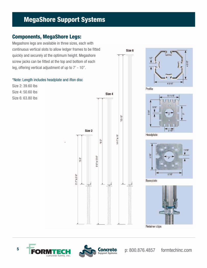
Components, MegaShore Legs:Megashore legs are available in three sizes, each with
continuous vertical slots to allow ledger frames to be fitted
quickly and securely at the optimum height. Megashore
screw jacks can be fitted at the top and bottom of each
leg, offering vertical adjustment of up to 7’ - 10”.
*Note: Length includes headplate and iflon disc
Size 2: 39.60 lbs
Size 4: 50.60 lbs
Size 6: 63.80 lbs
p: 800.876.4857 formtechinc.com

Concrete Support Systems Method Statement 6
The allowable leg load is determined by the floor to soffit height,
the number of ledger frames in height or jack extension
Notes: • It is assumed the formwork is restrained from horizontal movement at the formwork level.
• Ledger frames to be fixed in the optimum position.
• Maximum distance between ledger frames not to exceed 6’-6” between top and bottom
chords of ledger frames. This rule also applies on floor to soffit heights greater than 36’.
• On propping heights over 36’ refer to Concrete Support Systems’ Design Services for advice.
On the higher propping heights an additional level of frames may be required for
ease of erection and stability. Minimum height to base ratio = 4:1.
MegaShore Support Systems

p: 239.330.7614 f: 239.330.7958 www.concretesupportusa.com7
MegaShore Support System Load Charts
MegaShore Frame Loads
MegaShore Frame Loads
p: 800.876.4857 formtechinc.com

Concrete Support Systems Method Statement 8
MegaShore Support System Load Charts
MegaShore Frame Loads
Megashore Screw Jack Extension

p: 239.330.7614 f: 239.330.7958 www.concretesupportusa.com9
Brief DescriptionThe HV Support System shoring system is
recognised as the leading product in its field by
many professionals in the construction and civil
engineering industries.
Comprising two main components; legs and
frames, together with a comprehensive range of
accessories, the HV Support System offers one of
the quickest, most effective and versatile means of
providing rapid support and access solutions in an
enormous variety of situations.
The system can be used in both ‘flying table’
and erect and dismantle applications and is ideal
for multi-story structures, water reservoirs and
soffit situations where mobility and ease of
handling are required.
With the majority of components being
manufactured from high grade aluminium
to patented designs, the HV Support System
possesses an exceptionally high strength to weight
ratio which facilitates rapid erection, whilst its
excellent corrosion resistance and robust build
quality assure long term durability.
The HV Support System is designed to reduce labor
costs, increase site efficiency, improve safety and
meet the demands of today’s construction and civil
engineering techniques.
Technical specifications• Lightweight components can be
easily handled by one man
• Megashore can be loaded
up to 18.0 Kips per leg
• 7’ - 10” of jack adjustment
with jacks top and bottom
• Two components for fast, efficient
erection and dismantling
• No loose fittings
• Rigid connection between HV Legs and
frames self-aligns the system
• Continuous vertical slots on the HV legs
allow ledger frames to be positioned at
convenient working heights
• One system suitable for erect and dismantle
shoring and large, rigid flying tables for
versatility and economy
• Modular components easily adapt
to height and width variations
• Accessories include rocking headplates, guard
post brackets, access platforms, cantilever
frames and a full range of safety components.
HV Support System
p: 800.876.4857 formtechinc.com

Concrete Support Systems Method Statement 10
HV Support System4’ 5’
-9”
up to
10’
7’-9
” up
to 1
2’ 9’-6
” up
to 1
3’-1
0”
217.
1 cm
/ 7’
1.5
”
172.
2 cm
/ 5’
7.8
”
127.
2 cm
/ 4’
2.1
”
4’ ext.
Standard
Midi
Maxi

p: 239.330.7614 f: 239.330.7958 www.concretesupportusa.com11
HV Leg EndplateThe HV Leg is made out of
Aluminum and the Endplate
is made out of Aluminum
with a thickness of 3/8”.
Screw Jack EndplateThe HV Screw Jack is made
out of high strength Steel
and the Endplate is also Steel
with a thickness of 5/16”.
The Hole Pattern on all Endplates is the same
101.5
125
80
51
44
150
30.5 17
13
150
HV Support System
7.3”
18.5cm
6.3c
m
62.5
”
169.
0 cm
/ 5’
6.5
”
136.
0 cm
/ 4’
5.5
”32
cm
/ 1’
.625
”
Collar Nut for Jack
Screw Jack Endplate
Lite Jack 130 cmHV Screw Jack 130 cm
p: 800.876.4857 formtechinc.com

Concrete Support Systems Method Statement 12
HV Support System

p: 239.330.7614 f: 239.330.7958 www.concretesupportusa.com13
HV Support System Load Charts
p: 800.876.4857 formtechinc.com

Concrete Support Systems Method Statement 14
Components for Ledger Frame
A range of six ledger frames is available. Note: Frame lengths shown are in feet and center to center of Legs.

p: 239.330.7614 f: 239.330.7958 www.concretesupportusa.com15
Alu Beam
Component BeamsManufactured from extruded aluminium section, Alu Beams offer a lightweight, easy to handle solution for decking/soffit applications.
p: 800.876.4857 formtechinc.com

Concrete Support Systems Method Statement 16
Twin Beam
Twin and Insert Beam

p: 239.330.7614 f: 239.330.7958 www.concretesupportusa.com17
Twin Beam Load Charts
p: 800.876.4857 formtechinc.com

Concrete Support Systems Method Statement 18
Secondary Beams

p: 239.330.7614 f: 239.330.7958 www.concretesupportusa.com19
Method of ErectionThe method of erection/dismantling detailed below is not mandatory. It is intended to be used as an initial
guide. When familiarity has been gained with the equipment, a preferred method of erection may develop.
1. Set the jack collar nuts in the approximate position to give the correct jack extension. Then insert
the jack into the ends of the prop so that the collar nut engages with the retainer clip.
2. Place the prop, complete with jacks, at approximately the required leg centers on the
ground, mark the prop 15” from the Iflon washer or leg end plate to get the location of the
Mega Frame, introduce the Mega Frame of the correct length between them and secure this in
position. It will be found that the operation of tightening the ‘T’ bolts will be facilitated if the middle
‘T’ bolt is left until last. It will be necessary to completely unscrew wing nuts before attempting to
engage the T bolt. When the line on the end of the T bolt is in line with the slot in the outer leg, the
‘T’ bolt has been positioned correctly. The T bolt can be hand tied but with a torque of 440 Lbsin.
3. A further pair of props may now be assembled in the same fashion and
an additional pair of Mega Frames fitted vertically to them.
4. The two assemblies may now be raised until the props are vertical and the exposed ends of
the Mega Frames connected to the other pair of props to form a four legged tower.
5. Mega Frames can be hung off any face of this tower and the erection
continued until the desired shoring area has been achieved.
6. If the shoring requires more than one lift of Mega Frames and prop, this can be achieved by
working off a temporary platform resting on the previously erected Mega Frames. The next lift of
legs is inverted and connected to the first lift by using Mega Connection Brackets, followed by
assembly of the Mega Frames. If scaffold boards are used, transom units or tubular intermediate
transoms would be required to limit the board span to 4’-0”. Temporary tubular handrails can, if
required, be connected to the props by means of the Mega Half Coupler. It is also possible
to connect tubular guard posts to the ledger frames using standard scaffold fittings.
Site Safety is YOUR Responsibility...
p: 800.876.4857 formtechinc.com

Concrete Support Systems Method Statement 20
7. An alternative to #6 above is to assemble a tower as #1 to #4 above, crane handle the
tower onto the first tower and connect the end plates with Mega Connection Brackets.
8. Lacing and bracing, when required, may be added when the structure
is standing, but must be in place before the working load is applied.
9. Mega Alum Beams can now be placed on top of the jack or
prop and must be secured with at least one Mega Clamp R12x50.
10. Secondary beams (i.e. AH20, H20) are then placed on top of the Mega Alum Beam at
predetermined centers and fixed by the Mega Clamp R12x100 at each intersection with
the Mega Alum Beam.
11. All narrow width structures should be stabilized against overturning from
either wind forces or horizontal loading due to construction loads.
Site Safety is YOUR Responsibility...

p: 239.330.7614 f: 239.330.7958 www.concretesupportusa.com21
Stage 1
Note A: Min. dimension from work platform to
underside of primary beam must be 3’-9”
Note B: Fully boarded platform moved
in direction of Shoring
Note C:Initial secondary’s taken from ground / slab
and manhandled onto Mega Alum Beams.
Once sufficient ply deck is laid then secondary
bundles can be landed on the ply decking.
Erection Guide
p: 800.876.4857 formtechinc.com

Concrete Support Systems Method Statement 22
Erection Guide
Stage 2
IMPORTANT NOTE:All Shoring erection to be carried out from intermediate work/crash platform

p: 239.330.7614 f: 239.330.7958 www.concretesupportusa.com23
Stage 3
Erection Guide
p: 800.876.4857 formtechinc.com

Concrete Support Systems Method Statement 24
1. Begin dismantling operation by lowering the jacks with spanner.
2. Release secondary beams by undoing the Mega Clamp R12x100 and passing each beam to the
ground from an intermediate working platform.
3. Release Mega Alum Beams by undoing the Mega Clamp R12x50 and passing each beam to the
ground from an intermediate working platform.
4. Stripping of shoring should begin by releasing one end of one Mega Frame at all three locations
and repeat this procedure for the adjacent Mega Frame which runs off at right angles.
5. The above procedure will then release a leg, leaving two Mega Frames “hanging” from other props.
6. The Mega Frames should now be removed by following process
7. Continue repeating processes 4 and 5 until all shoring is removed.
8. On shoring structures greater than one leg in height, all works as previously described should be
carried out from safe, temporary working platforms as previously recommended.
Method of Dismantling

p: 239.330.7614 f: 239.330.7958 www.concretesupportusa.com25
The following checklist should be adhered to prior to the placement of concrete:
1. Ensure plumbness of props.
2. Ensure that all spring loaded wing nuts are tight with a torque of 440 Lbsin on Mega Frames
(over-exposed thread on ‘T’ bolt indicates otherwise).
3. Ensure that jack extensions are within design parameters.
4. Ensure that jack collar nut is properly located in prop (retainer clip securely fixed).
5. Ensure that the jack base plate/head plate maintains positive friction against floor slab.
6. Ensure that the size, number and location of Mega Frames are as per design drawings.
7. If props are extended (2 props or extension legs) make sure each connection uses
2 Mega Connection Brackets and wing nuts are tightened to the required torque of 440 Lbsin.
8. If using jacks at the top of the shoring, ensure items 3 and 4 above are followed and that
2 Mega Clamps R12x50 are used to locate jacks securely to underside of Mega Alum Beams.
9. Ensure that Mega Alum Beam spans are no greater than those shown in design drawings.
10. Ensure spacing and span of secondary beams are no greater than those shown in design drawings.
11. Ensure all/any damaged parts are removed and replaced immediately.
12. Ensure the proper safety procedures are adopted to facilitate the above items in compliance with
construction and health and safety working regulations.
Safety Checklist
p: 800.876.4857 formtechinc.com
Concrete Support Systems Method Statement 26
Method of ErectionThe method of erection/dismantling detailed below is not mandatory. It is intended to be used as an initial
guide. When familiarity has been gained with the equipment, a preferred method of erection may develop.
For the Twin and Insert Beam system different kind of support legs can be used. These are Mega Props
or HV Props. For easier understanding in the description below, all supports will be called Legs.
1. Set the leg jack collar nuts in the approximate position to give the correct leg jack extension.
Then insert the jack into the ends of the leg so that the collar nut engages with the retainer clip.
2. Place the legs, complete with jacks, at approximately the required leg centers on the ground, mark
the Leg 15” from the Iflon washer or leg end plate to get the location of the Mega Frame, introduce
the Mega Frame of the correct length between them and secure this in position. It will be found that
the operation of tightening the ‘T’ bolts will be facilitated if the middle ‘T’ bolt is left until last. It will
be necessary to completely unscrew wing nuts before attempting to engage the T bolt. When the
line on the end of the T bolt is in line with the slot in the outer leg, the ‘T’ bolt has been positioned
correctly. The T bolt can be hand tied but with a torque of 440 Lbsin.
3. A further pair of legs may now be assembled in the same fashion and an
additional pair of Mega Frames fitted vertically to them.
4. The two assemblies may now be raised until the legs are vertical and the exposed ends of the
Mega Frames connected to the other pair of legs to form a four legged tower. Ensure that the 15”
distance from the Iflon washer or leg end plate, to the Mega Frame appears on all 4 legs.
5. Place Twin Beams on top of the legs and secure them with Mega Clamp R12x50.
6. Introduce the Insert Beam to the Twin Beam and add support Leg. Secure support leg to insert
beam with Mega Clamp R12x50.
Twin Beam Support System

p: 239.330.7614 f: 239.330.7958 www.concretesupportusa.com27
7. Adjust the extended width of the insert beam according to proved drawings.
If insert beam is used on both sides of twin beam, repeat above steps.
8. Secondary beams (i.e. AH20, H20) are then placed on top of the twin and insert beam at
predetermined centers and fixed by the Mega Clamp R12x100 at each intersection with the
twin and insert beam.
9. All narrow width structures should be stabilized against overturning from either wind forces
or horizontal loading due to construction loads.
Erection Guide, Stage 1
Twin Beam Support System
p: 800.876.4857 formtechinc.com

Concrete Support Systems Method Statement 28
Twin Beam Support System
Stage 2
Stage 3

p: 239.330.7614 f: 239.330.7958 www.concretesupportusa.com29
Stage 4
Twin Beam Support System
Method of Dismantling 1. Begin dismantling operation by lowering the jacks.
2. Release secondary beams by undoing the Mega Clamp R12x100 and passing each beam to the
ground from an intermediate working platform i.e. a ladder.
3. Release insert beams by undoing the Mega Clamp R12x50 and lowering the leg. Passing each
beam and Leg to the ground from an intermediate working platform i.e. ladder.
4. Release twin beam by undoing the Mega Clamp R12x50 and passing each beam to the ground
from an intermediate working platform i.e. ladder.
5. Release one Mega Frame by undoing the wing nuts and put them to the ground.
6. Lower the jacks to have enough space to flip the tower 90 degrees.
7. Take apart the Mega Frames from the legs.
8. On shoring structures greater than one leg in height, all works as previously described should
be carried out from safe, temporary working platforms as previously recommended.
p: 800.876.4857 formtechinc.com

Concrete Support Systems Method Statement 30
Safety ChecklistThe following checklist should be adhered to prior to the placement of concrete:
1. Ensure plumbness of legs.
2. Ensure that all spring loaded wing nuts are tight with a torque of 440 Lbsin. on Mega Frames
(over-exposed thread on ‘T’ bolt indicates otherwise).
3. Ensure that jack extensions are within design parameters.
4. Ensure that jack collar nut is properly located in leg (retainer clip securely fixed).
5. Ensure that the jack base plate/head plate maintains positive friction against floor slab.
6. Ensure that the size, number and location of Mega Frames are as per design drawings.
7. If legs are extended (2 legs or outer ext) make sure each connection uses 2 connection brackets
and wing nuts are tightened to the required torque of 440 Lbsin.
8. If using jacks at the top of the shoring, ensure items 3 and 4 above are followed and that 2 Mega
Clamps R12x50 are used to locate jacks securely to underside of twin and insert beams.
9. Ensure that insert beam spans are no greater than those shown in design drawings.
10. Ensure spacing and span of secondary beams are no greater than those shown
in design drawings.
11. Ensure all/any damaged parts are removed and replaced immediately.
12. Ensure the proper safety procedures are adopted to facilitate the above items in compliance
with construction and health and safety working regulations.
Twin Beam Support System

p: 239.330.7614 f: 239.330.7958 www.concretesupportusa.com31
IntroductionThe following identifies the components required and their proper use with a step by step procedure
for stripping, flying and landing a MegaShore Table. Instructions are provided for standard tables.
GeneralIt is essential that these procedures are fully understood before the equipment is used. It is, therefore,
recommended that all personnel using the equipment on the first occasion should be supervised by a
competent and this discipline trained person.
There may be occasions when it is necessary for operatives to work adjacent to unguarded slab edges.
In all such cases operatives should wear suitable anchored safety harnesses. In addition, all other site
personnel should be made aware of such short duration hazards.
Particular attention should be paid by site management to ensure that crane signaling systems comply
with ruling regulations and that laid down procedures are fully understood and complied with.
Loose materials or equipment must not be transported on tables during moving and flying operations. At
no time during the operations is it necessary or desirable to exert undue force, either manually or through
the equipment.
Flying and Stripping EquipmentMega Trolleys are used in the stripping and flying procedure of a Megashore Table. A minimum of 2
trolleys/castors are used for the movement of the table. 2 trolleys are used adjacent to the second row
of legs in from the front of the table. These positions may vary depending on size and weight of table.
MegaShore Tables
p: 800.876.4857 formtechinc.com

Concrete Support Systems Method Statement 32
Stripping and Flying ProcedureBefore any stripping takes place, all obstructions to the safe movement of the table must be removed!
1. Break bond between slab and decking by lowering the collar nuts on the jack thus creating
the first stripping action. Mega Spanner must be used for this action.
2. Place the Mega Trolleys as instructed in the drawing. Basic position of Mega Trolleys is in the
second bay from edge and last bay on opposite side (see drawing above). Raise the Mega Trolley
till props come free.
MegaShore Tables

p: 239.330.7614 f: 239.330.7958 www.concretesupportusa.com33
3. With weight of table now being carried by the Mega Trolleys, retract the
remaining jacks to provide sufficient clearance for moving.
The table is now in the lowered position
MegaShore Tables
p: 800.876.4857 formtechinc.com

Concrete Support Systems Method Statement 34
MovingTo enable tables to be removed horizontally it is recommended that electric chain hoists are used to allow
compensation of lifting chains. Make a stop to the slab end.
4. After removing slab edge protection, the table should be pushed until the first row of props is
clear of the slab. Now the crane ropes can be attached to the table. Attach crane rope around
the props for safe connection.
5. Continue pushing table (helped now by pulling action of crane) until Mega Trolley is close to
the edge of building. Level the table by using the chain hoist. After table is leveled, release
and take out trolley.
MegaShore Tables

p: 239.330.7614 f: 239.330.7958 www.concretesupportusa.com35
6. The table is now ready to be
completely cleared from the slab
and lifted to the next bay or floor
above. If necessary, Mega Trolleys
can be used again to move table to
final position.
7. When table stays in final position,
site engineers can start leveling
table to final pour heights.
8. It is suggested at this stage, if
required, the props for reshoring
are installed at the necessary
positions.
MegaShore Tables
p: 800.876.4857 formtechinc.com

Concrete Support Systems Method Statement 36
Safety Checklist • Allnarrowwidthtablesshouldbestabilizedagainstoverturningfrom
either wind forces or horizontal loading due to construction loads.
• Whereoperativesarerequiredtoleanoveredgesoftheslab,
a suitable harness must be worn and appropriately fixed.
• Beforemovingtable,makesure,themovementareaisfreeofdebrisorotherdisturbingmaterial
• Makesure,thereisenoughclearancebetweenthefloorandthejacks.
• Makesure,thereisenoughclearancebetweenslabandtopoftable.
• CheckallconnectionsoftheMegaFramesandMegaClampstoensure,
all wing nuts are tighten to the required strength of 440 Lbsin torque.
• The225AlumStringerBeamshavetobefullyconnectedwithspliceplatesatallboltholes.
• Ensurethatallretainerclipsareinworkingordertoholdthejackinplace.
If not, replace retainer clips immediately. Do not fly table with broken retainer clips
• Ifusingjacksatthetopoftheshoringensurethatthescrewjackisconnectedtotheleg
with retainer claws and that 2 Mega Clamps R12x50 are used to locate jacks securely to
underside of Mega Alum Beams.
• Ensuretableweightdoesnotexceedcranecapacity
• Checklandingareafordebrisorotherdisturbingmaterial.
• Movetableswithcare.Alwayswatchyourcoworkersandcommunicatewiththem.
• Makeacommunicationplanwiththecraneoperatorsoboth
of you are on the same page and understand each other.
• Onlyonepersonshouldcommunicatewiththecraneoperatortoavoidconfusionandmistakes.
• Checkforsecureattachmentofthecraneropes.Theropes
should always go around the props and Alum Beams.
• Makesure,the“flyingarea”isfreeoftrafficandcoworkers.Prepareasignal
when the flying process starts so your coworkers can pay attention.
MegaShore Tables

p: 239.330.7614 f: 239.330.7958 www.concretesupportusa.com37
Method of ErectionThe method of erection/dismantling detailed below is not mandatory. It is intended to be used as an initial
guide. When familiarity has been gained with the equipment, a preferred method of erection may develop.For
the twin and insert beam system different kind of support legs can be used. These are Mega Props, HV Props
and HV MAXI Props. For easier understanding in the description below, all supports will be called legs.
1. Set the leg jack collar nuts in the approximate position to give the correct leg jack extension.
Then insert the jack into the ends of the leg so that the collar nut engages with the retainer clip.
2. Place the legs, complete with jacks, at approximately the required leg centers on the ground, mark
the leg 15” from the Iflon washer to get the location of the Mega Frame, introduce the Mega Frame
of the correct length between them and secure this in position. It will be found that the operation of
tightening the ‘T’ bolts will be facilitated if the middle ‘T’ bolt is left until last. It will be necessary to
completely unscrew wing nuts before attempting to engage the T bolt. When the line on the end of
the T bolt is in line with the slot in the outer leg, the ‘T’ bolt has been positioned correctly. The T bolt
can be hand tied but with a torque of 440 Lbsin.
3. A further pair of legs may now be assembled in the same fashion
and an additional pair of Mega Frames fitted vertically to them.
4. The two assemblies may now be raised until the legs are vertical and the exposed ends of the
Mega Frames connected to the other pair of legs to form a four legged tower. Ensure that the 15”
distance from the Iflon washer to the Mega Frame appears on all 4 legs.
5. Additional Mega Frames are now introduced to the tower,
followed by attaching the legs to build a 8 leg tower.
6. The twin beam is now attached to the on the middle
pair of legs and secured with Mega Clamp R12x50.
Twin Beam Tables
p: 800.876.4857 formtechinc.com

Concrete Support Systems Method Statement 38
7. Insert beam is now inserted into the twin beam and extended to the appropriate
length according to the drawing. Secure insert beam to leg with R12x50.
8. Secondary beams (i.e. AH20, H20) are now placed on top of the twin and insert beam
in correct span according to drawing. Secondary beams must be secured on twin and
insert beam with R12x100/
9. Decking is now placed on top of secondary beams and secured with nails.
Twin Beam Tables
Stage 1
Build 8 leg tower according to drawing

p: 239.330.7614 f: 239.330.7958 www.concretesupportusa.com39
Stage 2
Attach twin and insert beams to tower.
Stage 3
Finish table by attaching secondary beams with R12x100 and decking.
For detailed assembly instructions see page 13-17
Twin Beam Tables
p: 800.876.4857 formtechinc.com

Concrete Support Systems Method Statement 40
Twin Beam Tables
Stripping and Flying ProcedureBefore any stripping takes place, all obstructions to the safe movement of the table must be removed
1. Break bond between slab and decking by turning the collar nuts thus creating first stripping action.
2. Place the Mega Trolleys to the Mega Frames as instructed in the drawing. Basic position of Mega
Trolleys is in the second bay from edge and last bay on opposite side (see drawing above). Raise
Mega Trolleys by turning the handle clockwise until legs come free.

p: 239.330.7614 f: 239.330.7958 www.concretesupportusa.com41
Twin Beam Tables
3. With the weight of the table now being carried by the Mega Trolleys,
retract the remaining jacks to provide sufficient clearance for moving.
The table is now in the lowered position and ready to move
p: 800.876.4857 formtechinc.com

Concrete Support Systems Method Statement 42
Twin Beam Tables
MovingTo enable tables to be removed horizontally it is recommended that
electric chain hoists are used to allow compensation of lifting chains.
4. After removing slab edge protection, the table should be pushed until the first row of
legs is clear of the slab. Now the crane ropes can be attached to the table. Attach crane
ropes around leg and beam for safe connection.
Continue pushing table (helped now by pulling action of crane) until Mega Trolley is close to edge of the
building. Level the table by using the chain hoist. After table is leveled, release and take out trolley.

p: 239.330.7614 f: 239.330.7958 www.concretesupportusa.com43
Twin Beam Tables
6. The table is now ready to be
completely cleared from the slab
and lifted to the next bay or floor
above. If necessary, Mega Trolleys
can be used again to move table
to final position.
7. When table stays in final position,
site engineers can start leveling
table to final pour heights.
8. It is suggested at this stage, if
required, the props for reshoring
are installed at the necessary
positions.
p: 800.876.4857 formtechinc.com

Concrete Support Systems Method Statement 44
Safety Checklist
• Allnarrowwidthtablesshouldbestabilizedagainstoverturningfromeitherwindforcesor
horizontal loading due to construction loads.
• Whereoperativesarerequiredtoleanoveredgesoftheslab,asuitableharnessmustbe
worn and appropriately fixed.
• Beforemovingtable,makesure,themovementareaisfreeofdebrisorotherdisturbingmaterial
• Makesure,thereisenoughclearancebetweenthefloorandthejacks.
• Makesure,thereisenoughclearancebetweenslabandtopoftable.
• CheckallconnectionsoftheMegaFramesandMegaClampstoensure,allwingnutsaretighten
to the required strength of 440 Lbsin torque.
• Ensurethatallretainerclipsareinworkingordertoholdthejackinplace.Ifnot,replace
retainer clips immediately. Do not fly table with broken retainer clips.
• Ifusingadditionaljacksatthetopoftheshoringensurethatthescrewjackisconnectedtothe
leg with retainer claws and that 2 Mega Clamps R12x50 are used to locate jacks securely
to underside of Mega Alum Beams.
• Ensuretableweightdoesnotexceedcranecapacity
• Checklandingareafordebrisorotherdisturbingmaterial.
• Movetableswithcare.Alwayswatchyourcoworkersandcommunicatewiththem.
• Makeacommunicationplanwiththecraneoperatorsobothofyouareonthesame
page and understand each other.
• Onlyonepersonshouldcommunicatewiththecraneoperatortoavoidconfusionandmistakes.
• Checkforsecureattachmentofthecraneropes.Theropesshouldalways
go around the props and Alum Beams.
• Makesure,the“flyingarea”isfreeoftrafficandcoworkers.Prepareasignalwhentheflying
process starts so your coworkers can pay attention.
Twin Beam Tables
p: 239.330.7614 f: 239.330.7958 www.concretesupportusa.com45
Typical Infill Methods15” maximum width infill areas between tables
Erection a. Cut plywood to suitable width.
b. Place plywood in gap between tables (plywood supported by existing secondary beams).
If plywood is positioned from above, operatives have to wear a suitable safety harness.
Dismantling c. Lower tables
d. Remove plywood infill. If height is above 7 ft, a temporary access platform will be required.
e. Reposition tables and then follow erection sequence above.
15” to 36” wide infill areas between table erection
Typical Infill MethodsErection
a. Cut plywood to suitable width.
b. Place plywood in gap between tables (plywood supported by existing secondary beams).
If plywood is positioned from above, operatives have to wear a suitable safety harness.
c. Support plywood at mid span by means of temporary stringer beam and suitable props.
Infill widths shall not exceed what has been indicated on the project-specific drawings.
Typical Infill MethodsDismantling
d. Remove temporary props and stringer beams.
e. Lower tables.
f. Remove plywood infill. If height is above 7 ft, a temporary access platform will be required.
g. Reposition tables and then follow erection sequence above.
Concrete Support Systems Infill Methods
p: 800.876.4857 formtechinc.com

Concrete Support Systems Method Statement 46
Notes

HV S
uppo
rt S
yste
m
p: 239.330.7614 f: 239.330.7958info@concretesupportusa.comwww.concretesupportusa.com
48575 Downing StreetWixom, MI 48393 800.876.4857 [email protected]
formtechinc.com
48575 Downing StreetWixom, MI 48393 800.876.4857 [email protected]
formtechinc.com