method statement sample
TRANSCRIPT

Appendix D Construction Method Statement

EVELEIGH HERITAGE WALK CONSTRUCTION METHOD STATEMENT
1 SCOPE OF METHOD STATEMENT This method statement relates to the construction of foundations and superstructures for a pedestrian overbridge across the rail corridor at the western end of the Redfern Station platforms. The scope of work comprises the construction of the footbridge and associated pedestrian ramps and stairs on North Eveleigh Plaza and the Australian Technology Park, on the north and south sides of the corridor respectively.
2 REFERENCE DRAWINGS SK 112 Rev C: Option 7- Bridge alignment around existing buildings. SK 113 Rev B: Option 7- Landing- Australian Technology Park. SK 114 Rev B: Option 7- Landing- North Eveleigh. SK 117 Rev : Option 7- Bridge over rail corridor with structural net. SK 126 Rev B: Option 7- Schematic Elevation- North Eveleigh Plaza towards Wilson Street. SK 127 Rev : Structural bridge sections. SK 129 Rev: Option 7- Schematic Elevation- North Eveleigh Plaza towards rail corridor. SK C32: North Eveleigh Ramp Option 1, 31 March 2008. SK C36: ATP Ramp and Stairs Option 1, 2 April 2008. SKA 190: Bridge Construction – Stage 1. SKA 191: Bridge Construction – Stage 2A. SKA 192: Bridge Construction – Stage 2B. SKA 193: Bridge Construction – Stage 2C. SKA 194: Bridge Construction – Stage 3A. SKA 195: Bridge Construction – Stage 3B.
Appendix D Construction Method Statement Page 1 of 26 Revision 4 10/07/2008
EVELEIGH HERITAGE WALK CONSTRUCTION METHOD STATEMENT
3 GENERAL APPROACH TO CONSTRUCTION AND CONSTRUCTION TIME
3.1 General Approach The construction staging of the project will involve activities on the sites of the North Eveleigh Plaza and the Australian Technology Park, with sporadic works during night possessions and specific weekend possessions of some of the tracks of the rail corridor. In parallel with the site construction activities, prefabrication of the bridge and ramp structures will proceed off-site. The work will culminate with the erection of the pedestrian bridge over the rail corridor, to be carried out during a special weekend possession of most of the tracks in the rail corridor, followed by completion of the bridge internal finishes and completion of construction of the access ramps on the North Eveleigh Plaza and the Australian Technology Park sites. Construction activities on the North Eveleigh Plaza and Australian Technology Park sites will include:
• Site establishment, including offices, services and amenities. • Piling for the support columns of the pedestrian bridge. The northern column is
located in the northern section of the rail corridor, whilst the south column is well outside the rail corridor.
• Piling for the support columns of the ramps and access stairs.
• Construction of footings and columns for the bridge, stairs and ramps.
• Construction of temporary fences and access gates and if required, temporary
noise and dust abatement facilities around the site compounds.
• Construction of temporary environmental protection works, including stormwater management, and truck wheel washing facilities.
• Construction of temporary structures and footings required for the launch of the
bridge from the North Eveleigh Plaza site. Work will include preparation of hardstand areas for crane access and a long steel structure for the assembly and launching of the bridge.
• Erection and assembly of the bridge sections on the temporary launch structure
erected on the north site compound. The assembled bridge should include the protection mesh, precast concrete slab shells for the floor and temporary timber sides to prevent objects falling to the track during and after the launch.
• Installation and testing of the launching equipment.
• Placement and erection of the 400-t crane in the south side of the corridor, within
the Australian Technology Park. The crane will need to be erected the day before the launch.
• Works on the corridor to be carried out in night and/or weekend possessions well
in advance of to the launch include:
Appendix D Construction Method Statement Page 2 of 26 Revision 4 10/07/2008
EVELEIGH HERITAGE WALK CONSTRUCTION METHOD STATEMENT
o Installation of NJ-barriers or other type of safety fences where required to separate the construction sites from the live rail zones (danger zones).
o Site survey of the area intended for the transit and location of the cranes to be involved in the launch of the bridge.
o Relocation or construction of protection works of existing services likely to be affected by the launching operations.
Construction activities on the weekend possession for the launching of the bridge include:
• Coordination with Rail Corporation staff regarding power outage and other safety procedures.
• Confirmation that the tracks are closed for the weekend and the first night.
• Installation of floodlights and other contingency measures determined by the risk
analysis.
• Launching operation.
• Installation of the bridge on its permanent bearings. Based on the preliminary design estimate of the erection mass of the bridge, the current erection procedure is based on the use of a 400-t crane placed in the Australian Technology Park, outside the rail corridor.
3.2 Construction Time The duration of the project depends on the availability of a track possession to carry out the erection of the bridge. Construction of the foundations, columns and ramps can be carried out in normal times. However, completion of the ramps will be constrained by the erection of the bridge and therefore by the availability of a suitable track possession. It is estimated that stage 1 of the project, comprising construction of the footings for bridge and ramps, bridge columns, temporary structures and prefabrication of the bridge and precast elements for the ramps can be completed over a period of six to seven months after award. Stage 2 of the project is the launching of the bridge, which will be completed in one weekend possession. Stage 3 of the project, comprising construction of the access ramps and bridge finishes, can be completed over a period of four months.
Appendix D Construction Method Statement Page 3 of 26 Revision 4 10/07/2008
EVELEIGH HERITAGE WALK CONSTRUCTION METHOD STATEMENT
4 CONSTRUCTION SITES AND ACCESS As mentioned above, there will be construction compounds at the North Eveleigh Plaza and the Australian Technology Park sites, as well as in the rail corridor during approved rail possessions. Vehicular access to the Australian Technology Park site could be obtained from Cornwallis Street. The largest construction plant required to access this site will be the 400-tonne crane, which is self-propelled and of approximately 20-m long by 3-m wide with nine axles with pneumatic tyres. An auxiliary 90-tonne crane will be required to assemble the larger 400-tonne crane. The auxiliary crane is approximately 10-m long by 3-m wide. Additional plant required on the site includes 60 to 90-tonne cranes to erect the precast concrete shells of the main south column for the bridge and the structural precast concrete elements of the access ramps and stairs; smaller cranes to erect reinforcement cages, falsework and formwork elements; small excavators and spoil trucks; soil compaction equipment; and concrete mixers and pump trucks for placement of the concrete. At the present time, without a site-specific geotechnical investigation it is not expected that the excavation will involve rock. Vehicular access to the North Eveleigh Plaza site could be gained from Wilson Street. Plant required to access the site includes, excavators, small earth moving equipment to prepare the hard stand areas, spoil trucks, concrete mixers and concrete pumps, small cranes to handle reinforcement cages and formwork elements, and 60 to 90-tonne cranes to erect the precast concrete shells for the main north support column of the bridge, the temporary launching structure, the launching equipment, the structural precast elements for the ramps and stairs and to lift and assemble the bridge sections. It is expected that the bridge structure will be pre-fabricated off site in short sections of approximately 12-m, which will be lifted onto the temporary launching platform and joined together into the full-length bridge ready for launching. . At the present time, without a site-specific geotechnical investigation it is not expected that the excavation will involve rock. Major plant access to the rail corridor air space will be required on the south side only. The 400-tonne crane will need to be positioned approximately 3 metres from the proposed ramp and space will be required for the auxiliary crane needed to erect the 400-t crane.
Appendix D Construction Method Statement Page 4 of 26 Revision 4 10/07/2008
EVELEIGH HERITAGE WALK CONSTRUCTION METHOD STATEMENT
5 CONSTRUCTION OF THE PEDESTRIAN OVERBRIDGE
5.1 General The project includes construction of the two main bridge columns and foundations, and launching of a 70-m span prefabricated pedestrian overbridge. The bridge structure would have been prefabricated off site, brought to site in short lengths and pre-assembled on a launching platform constructed on the North Eveleigh Plaza site, on the same alignment as the bridge. The main support columns will be located adjacent to the north and south sides of the rail corridor and at least 4.3-m clear of the nearest tracks. The nearest tracks are the Up Main on the north side and the Down Illawarra on the south side. The columns will be constructed of reinforced concrete on piled foundations. It is envisaged that temporary safety fences or fenced NJ-barriers would be erected at a clear distance of 3.0-m from the centre line of the outer tracks mentioned above. The fences would be erected during the available appropriate possessions (configuration 1 and configuration 3). With the safety fences in place, construction of the bridge columns will proceed during normal working hours, outside rail possessions. The launching operation will be carried out in a weekend possession of the tracks on the southern side of the corridor, supplemented by a one-night possession of the northern tracks. It is envisaged that the launch operation will require the assistance of a 400-t crane placed on the site of the Australian Technology Park. The launched bridge will incorporate in addition to the full steel structure, the permanent protective mesh, precast floor slab shells to serve as permanent formwork for the final cast-in-situ floor, temporary timber sides, all electrical wiring and pipes required, and the overhead wiring protection awnings required by Rail Corporation. The capacity of the 400-t crane placed in the Australian Technology Park limits the total weight of the bridge during launching to 133.5 tonnes, comprised of: Structural steel: 85.0 t Mesh and protection: 10.0 t Concrete deck forms: 38.5 t Total erection weight: 133.5 t Work to be carried out after completion of the launch will include completion of the internal building work and services inside the bridge.
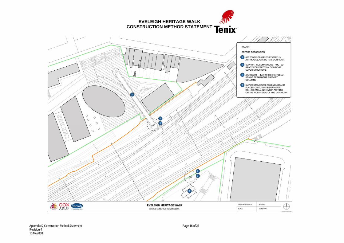
5.2 Staging Stage 1- Work Before the Launch Possession (Refer to Drawing SKA 190, Appendix A). The work will be carried out in the North Eveleigh Plaza and Australian Technology Park sites during normal working hours, from 7.00 am to 5.00 pm on week days and from 7.00 to 2.00 pm on Saturdays. Activities include:
• Site establishment.
Appendix D Construction Method Statement Page 5 of 26 Revision 4 10/07/2008
EVELEIGH HERITAGE WALK CONSTRUCTION METHOD STATEMENT
• Piling and construction of pile caps.
• Construction of bridge support columns. • Construction of footings and steel structures for the temporary launch structure
on the North Eveleigh Plaza site. The temporary launch structure should consist of an elevated platform supported on temporary columns and some of the permanent columns, constructed on the same alignment as the permanent bridge and of sufficient length to erect and assemble the bridge and appendages prior to launch.
• Construction of temporary jack platforms adjacent to the permanent columns.
The northern platform will also include a roller or sliding support that will carry a significant proportion of the weight of the bridge during the launch.
• Installation, testing and commissioning of the launching equipment. • Constructions of a flat, hard stand area for positioning of the 400-t crane on the
Australian Technology Park site.
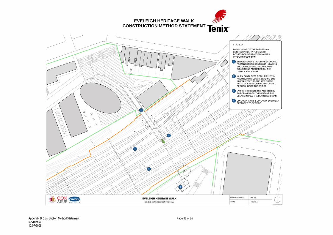
• Placing and erection of the 400-t crane the day before the launch. Stage 2- Launching Operation (Refer to Drawings SKA 191, SKA 192 and SKA 193, Appendix B, C and D). The work will be carried out during a weekend possession, and includes the following activities:
• Preliminary activities associated with rail safety. • Confirm power outage and track closures. • Implementation of safety contingency measures. • Start of launching operation, with bridge pushed southwards over the rail
corridor. Bridge to be supported on a temporary steel structure attached to and straddling the permanent north column. Bridge to be pushed over the corridor until the leading end cantilevers 21.875 m from the north column (approximately between the up and down Suburban tracks).
• At this stage the crane hooks and rigging are connected to the end of the bridge.
All activities related to the connection of the crane to the leading end of the bridge will be carried out from inside the bridge.
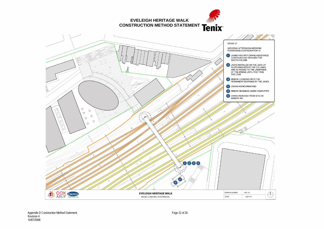
• Launching re-starts with the leading end supported by the crane. The crane
slews and luffs to follow the leading end of the bridge. • The process continues until the bridge reaches a position above the permanent
bearings atop the columns. • Jacks, previously installed on the sides of the columns, are extended to the
underside of the bridge to take over the load. The jacks are lowered until the bridge rests on its permanent bearings.
Appendix D Construction Method Statement Page 6 of 26 Revision 4 10/07/2008

EVELEIGH HERITAGE WALK CONSTRUCTION METHOD STATEMENT
• The jacks are removed. Completion of the connections of the bridge to the
bearings is carried out working on the platforms that support the jacks.
• Removal of all equipment or materials used for the launch from the rail corridor and hand over of the corridor to Rail Corporation.
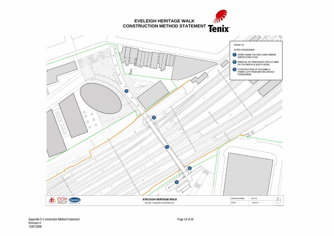
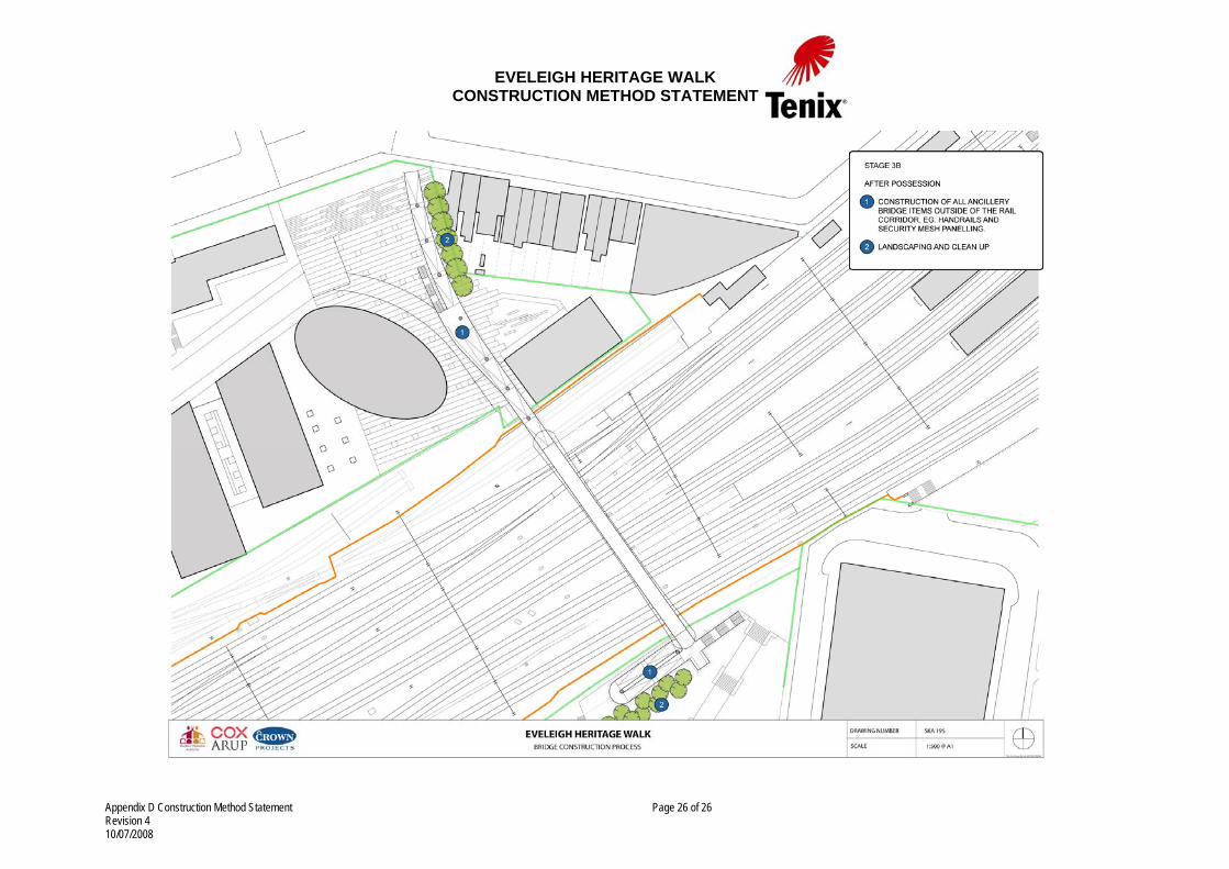
The launch operation is estimated to take approximately 15-hrs, including approximately 7 hours required for the leading end to cross the Suburban and Main lines. Stage 3- Work after Bridge Erection (Refer to Drawings SKA 194 and SKA 195, Appendix E and F). The work required after the erection of the bridge will be carried out outside rail possessions, during normal working hours, between 7.00 am and 5.00 pm on weekdays and from 7.00 am to 2.00 pm on Saturdays. The work required for the bridge will be carried out entirely within the bridge and will consist of construction of finishes, completion of services and construction of the structural connections to the access ramps. Adequate measures will be designed and implemented to avoid and prevent any possible effect on the operating rail tracks beneath. Access to the work site will be available from the north and south ends via the permanent ramps or any other temporary structure. Work to be completed post erection of the main structure of the bridge includes:
• Completion of the reinforced concrete in-situ floor. The concrete will be placed on precast concrete planks installed in the bridge before launching. The planks will become composite with the in-situ concrete to form the permanent floor and play any other structural role as designed.
• Installation of handrails and other safety structures.
• Installation of any services required, within conduits built in the structure of the
bridge.
• Completion of internal finishes.
• Connection to the access ramps.
5.3 Resources The following resources will be needed for construction of the bridge over the rail corridor: Materials
• Reinforced and prestressed concrete, precast and cast-in-situ.
• Structural steel.
Appendix D Construction Method Statement Page 7 of 26 Revision 4 10/07/2008
EVELEIGH HERITAGE WALK CONSTRUCTION METHOD STATEMENT
• Stainless steel wire mesh
• Pipes, conduits, electrical cables, telephones, CCTV.
Equipment
• Earth moving equipment for site preparation (eg. D7, D8 dozers, graders, excavators)
• Pile boring rigs.
• Excavators and spoil removal trucks.
• Scaffolding and formwork.
• Concrete construction plant (mixers, pumps).
• Plate compactors, vibratory roller compactors.
• Cranes for erection of falsework, structural steel and precast concrete.
• Flood lights for night work during track possessions.
• New Jersey barriers for demarcation of danger and safe zones.
• Bridge launching equipment, including high-tensile bars and hydraulic jacks.
• Hydraulic jacks for the final lowering of the bridge to its permanent bearings.
Human Resources Special staff qualified as PO4 (Rail Corporation) will be needed to supervise all operations near the live railway tracks.
5.4 Ancillary Construction Facilities The launching method of erection will require the following temporary ancillary facilities:
• Jacking platforms beside the permanent bridge columns. The jacks will temporarily support the bridge whilst lowering it to the permanent bearings.
• The launching platform. The launching platform should be constructed on the site
of the North Eveleigh Plaza, on the same alignment of the bridge. The bridge, which will be delivered to the site in segments, will be placed and assembled on the platform. Also, all of the bridge external appendages, such as the protection mesh, overhead wiring awnings and others, will be erected while the bridge rests on the launching platform. Also, internal finishes, conduits and other services may be installed prior to the launch, as permitted by the maximum erection weight limitation.
• Temporary support pad for the 400-t crane. An area in the Australian Technology
Park should be prepared flat and well compacted for the positioning of the crane during the launching operation.
Appendix D Construction Method Statement Page 8 of 26 Revision 4 10/07/2008
EVELEIGH HERITAGE WALK CONSTRUCTION METHOD STATEMENT
5.5 Potential Construction Impacts The potential construction impacts resulting from construction of the bridge include:
• Runoff.
• Noise.
• Dust Emissions. 5.5.1 Stormwater Management The main construction compound will be on the north side of the corridor, between the rail corridor and Little Eveleigh Street. The compound will include the work site for the construction of the piled foundations and bridge pier of the northern bridge support, as well as the site for the temporary structures and equipment required for the assembly and launch of the bridge. The temporary site drainage will need to be designed to collect the runoff, remove the silt and prevent it from flowing into the rail corridor. Where possible the collected runoff should be directed to an existing drain after the silt has been removed or to the street if acceptable by the relevant authorities. The other construction area is the site of the southern bridge pier. Similar precautions to prevent runoff flow to the corridor and the street should be taken. After construction the work compounds will be restored to their initial condition. The bridge will be designed to minimise any concentration of rainfall to the rail corridor.
5.5.2 Noise Most of the work before and after the erection of the bridge will be carried out on the North Eveleigh Plaza site. The site is near some residences, particularly in Little Eveleigh Street and Wilson Street. On the south side, the Australian Technology Park site, construction activities will involve construction of the bridge’s south column and the access ramp. The site is also near residential areas, particularly on Cornwallis Street. The construction activities prior and post the launching operation will take place during normal working hours and on Saturdays up to 2 pm. No night work should be necessary other than work within the rail corridor, which should occur during possessions and for this project, it is envisaged that only survey works may be required. During the launching operation, both the north and south sites will continually generate low levels of noise for the 48 hours of the weekend. Potential sources of noise include the piling rigs, crane operation, excavator operation, and operation of plate and vibratory roller compactors. If required, the noise impact may be mitigated by the use of temporary noise walls along the affected boundaries.
Appendix D Construction Method Statement Page 9 of 26 Revision 4 10/07/2008
EVELEIGH HERITAGE WALK CONSTRUCTION METHOD STATEMENT
5.5.3 Dust Emissions Dust is likely to be emitted during dry and windy days and affect the nearby residences and offices. Dust should be controlled by water spraying of the site when necessary.
5.6 Rail Safety Considerations.
5.6.1 Erection and dismantling of formwork Erection and dismantling of any formwork or falsework, required for construction of the main bridge columns, will be carried out outside the rail corridor. Crane operations will be under the supervision of a PO4 qualified staff and carried out under an agreed safety procedure. There will be no requirement to erect or dismantle any formwork or falsework over the rail corridor or over live rails. As stated below, all operations subsequent to the launch of the bridge will take place inside the bridge, which will be designed to ensure there is no risk of any object falling onto the tracks. Concrete placement for the columns and for the in-situ floor slab inside the bridge will utilise pumps. In the case of the north column, which is 4.3-m from the live track, a PO4 qualified officer will supervise the movement of the pump boom to ensure that it does not approach the Jersey barrier defining the safe and danger zones.
5.6.2 Cranage and other aerial movements The aerial movements required for the construction of the bridge and related ramps and stairs, involve bored piling, concrete works and crane operations. Piling will take place in non-possession periods, as it will be on places outside the rail corridor. The piling rigs will operate outside the corridor under the supervision of a PO4 qualified staff and subject to an appropriate operating procedure, implemented to ensure the booms never project beyond the fences into the corridor. The piling for the northern column will be designed so that all piles are within the safe working zone. For the construction of the pile-caps and bridge columns, any crane or concrete pump booms will need to operate clear of the safety fences, under supervision and following agreed operating procedures. The 70-m span bridge will be launched from the North Eveleigh Plaza site towards the south across the corridor. All the crane operations related to the erection and assembly of the pre-fabricated bridge structure will take place during non-possession periods on the area between the north boundary of the corridor and Little Eveleigh Street and will keep well clear of the Up Main track. An operating procedure will be developed to ensure the safety of the rail infrastructure during construction of any temporary structures and assembly of the bridge structure. The launch operation will be supplemented by the use of a 400-t crane standing on the Australian Technology Park site at approximately 30 to 32-m of the nearest track, clear of the rail corridor. The crane will be erected the day before the launching operation with the assistance of an auxiliary crane. The erection of the crane will be supervised by a PO4
Appendix D Construction Method Statement Page 10 of 26 Revision 4 10/07/2008
EVELEIGH HERITAGE WALK CONSTRUCTION METHOD STATEMENT
qualified staff and subject to an appropriate working procedure, to ensure the booms do not encroach into the rail corridor. The bridge will be at least 9.4 -m above the rail tracks and it will be well clear of the traction wires of the local, suburban and Main lines, which will remain in place as required for operation. Only the overhead wiring of the tracks shut down by the weekend possession chosen for the launch will need to be de-energised to ensure the safety of the staff and crane operation above it. The bridge’s in-situ floor and internal fit-out is envisaged to take place outside possessions. The bridge will be designed so that there is no risk of any object falling onto the live tracks beneath.
5.6.3 Physical Access to the Corridor It is not envisaged that crane or other plant access to the rail corridor will be required during the bridge launching operation. Access of personnel and minor equipment may be required, to install floodlights and carry out other precautionary works as determined by the risk analysis. Also, although at this stage it is envisaged that the crane hooks and rigging gear will be connected to the leading end of the bridge by staff working from the inside of the bridge, it is also possible that in the final analysis of the operation, a hi-rail cherry picker may be required to lift the staff to connect the hooks.
5.6.4 Track possessions and power outages The following track possessions and power outages are required to complete the project:
• One possession each of configurations 1 and 3: During possessions of configurations 1 and 3 NJ-barriers or safety fences are to be erected to separate the respective live tracks from the construction sites on the north and south sides of the corridor. The work in these possessions is expected to be added to any other maintenance activity already planned by RailCorp and will not require power outage. The extent of the fences is to be determined in conjunction with RailCorp.
• Night possessions: Work site survey of the area beneath the air space needed for
operation of the crane boom. This activity will not require power outage and may be carried out during consecutive night possessions.
• One weekend possession: A special weekend possession of configuration 15 or a
standard configuration 1A possession, supplemented by a Friday night long possession of the remaining operating tracks in the corridor is required to carry out the launch of the bridge. Power outage will be required for all the shut down lines, including the lines shut down for the night. The preferred weekend possession is configuration 1A. During a configuration 1A possession the Illawarra Line, the Illawarra Local Line and the Local Line are normally shutdown. On the Friday night of the launch, it would be also be required to shut down the Main and the Suburban lines for that night.
If a weekend configuration 15 was adopted for the launch, the normally shutdown lines (Local Line, the Suburban Line, the Main Line and the Illawarra Local Line from Redfern to the CBD) would need to be supplemented by shut down of the
Appendix D Construction Method Statement Page 11 of 26 Revision 4 10/07/2008
EVELEIGH HERITAGE WALK CONSTRUCTION METHOD STATEMENT
Illawarra Local Line and the Illawarra Line between Redfern and Erskineville Stations for the weekend.
Appendix D Construction Method Statement Page 12 of 26 Revision 4 10/07/2008
EVELEIGH HERITAGE WALK CONSTRUCTION METHOD STATEMENT
6 CONSTRUCTION OF THE PEDESTRIAN RAMPS AND STAIRS Construction of the pedestrian ramps and stairs will follow conventional methods of structural precast concrete erection and in-situ concrete construction. The timing of construction of some of the support columns and parts of the ramps will be affected by the activities associated with the launching operation. On the Australian Technology Park site, a large 400-tonne crane and the auxiliary crane will need to access the site and be erected in a position that conflicts with the ramp. Therefore, the construction of the ramp superstructure will need to be delayed until after completion of the launching of the bridge. On the North Eveleigh Plaza site, the launching structure, required to be on the same alignment of the bridge, will intersect the three southern spans of the ramp. In addition, depending on the location of the site access point from the street, construction of the remainder of the ramp and the stair may need to be delayed until after erection of the bridge.
Appendix D Construction Method Statement Page 13 of 26 Revision 4 10/07/2008

EVELEIGH HERITAGE WALK CONSTRUCTION METHOD STATEMENT
Appendix D Construction Method Statement Page 14 of 26 Revision 4 10/07/2008
EVELEIGH HERITAGE WALK CONSTRUCTION METHOD STATEMENT
APPENDIX A: SKA 190
Appendix D Construction Method Statement Page 15 of 26 Revision 4 10/07/2008
EVELEIGH HERITAGE WALK CONSTRUCTION METHOD STATEMENT
Appendix D Construction Method Statement Page 16 of 26 Revision 4 10/07/2008

EVELEIGH HERITAGE WALK CONSTRUCTION METHOD STATEMENT
APPENDIX B: SKA 191
Appendix D Construction Method Statement Page 17 of 26 Revision 4 10/07/2008
EVELEIGH HERITAGE WALK CONSTRUCTION METHOD STATEMENT
Appendix D Construction Method Statement Page 18 of 26 Revision 4 10/07/2008

EVELEIGH HERITAGE WALK CONSTRUCTION METHOD STATEMENT
APPENDIX C: SKA 192
Appendix D Construction Method Statement Page 19 of 26 Revision 4 10/07/2008

EVELEIGH HERITAGE WALK CONSTRUCTION METHOD STATEMENT
Appendix D Construction Method Statement Page 20 of 26 Revision 4 10/07/2008

EVELEIGH HERITAGE WALK CONSTRUCTION METHOD STATEMENT
APPENDIX D: SKA 193
Appendix D Construction Method Statement Page 21 of 26 Revision 4 10/07/2008
EVELEIGH HERITAGE WALK CONSTRUCTION METHOD STATEMENT
Appendix D Construction Method Statement Page 22 of 26 Revision 4 10/07/2008

EVELEIGH HERITAGE WALK CONSTRUCTION METHOD STATEMENT
APPENDIX E: SKA 194
Appendix D Construction Method Statement Page 23 of 26 Revision 4 10/07/2008
EVELEIGH HERITAGE WALK CONSTRUCTION METHOD STATEMENT
Appendix D Construction Method Statement Page 24 of 26 Revision 4 10/07/2008

EVELEIGH HERITAGE WALK CONSTRUCTION METHOD STATEMENT
APPENDIX F: SKA 195
Appendix D Construction Method Statement Page 25 of 26 Revision 4 10/07/2008
EVELEIGH HERITAGE WALK CONSTRUCTION METHOD STATEMENT
Appendix D Construction Method Statement Page 26 of 26 Revision 4 10/07/2008