methods and equipment for onshore geotechnical … geotechnical__ltd_eng.pdf · geotechnical...
TRANSCRIPT

Group of Service Companies “MORINZHGEOLOGIA”
Member of the Russian Oil & Gas Builders Union http://www.morinzhgeologia.ru/
METHODS AND EQUIPMENT FOR ONSHORE GEOTECHNICAL INVESTIGATIONS

2
The Group of Service Companies “Morinzhgeologia” is a Member of the Russian Oil & Gas Builders Union and is a partner of Non-Commercial Partnership “Central Association of Organisations Executing Engineering Surveys for Construction” (NP “Centrizyskaniya”) and has a Certificate of clearance for engineering-geological and geotechnical surveys. It has been certified by the European Agency Lloyds̀ Register Quality Assurance for the compliance with the requirements of the international standard ISO9001:2008 “QUALITY MANAGEMENT SYSTEMS” and ISO14001:2004 “ENV IRONMENTAL MANAGEMENT SYSTEMS”.

3
The activities of “Morinzhgeologia” are predominantly associated with the execution of geotechnical investigations in the Caspian Sea and onshore geotechnical investigations for the construction of structures. We have carried out investigations for the construction of objects, including the production facility of “LUKOIL-Nizhne volzhskneft’” in Ilyinka Township.
More detailed information about “Morinzhgeologia” i s contained in the Federal Reference Book of the Fuel and Energy Complex of Russia for 2009.

4
Onshore geotechnical investigations are carried out in accordance with the regulations and technical requirements of the set of regulations SP 11-105-97 – “Geotechnical Surveys for construction” of the State Committee of the Russian Federation for Construction, incorporating both geotechnical and geophysical methods of investigations. The following geotechnical methods are usually incorporated in the practice of geotechnical surveys:
• Geodetic support of geotechnical operations.
• Drilling of geotechnical boreholes.
• Cone penetration testing of soils with measurements of pore pressure СРТu (Cone penetration test with pore pressure-u);
• Cone penetration testing of soils with measurements of pore pressure and seismic acoustic channel SСРТu (Seismic CPTu);
• Standard penetration testing of soils (SPT).
• Vane testing of soils FVT (Field vane testing).
• Determination of physical and mechanical properties of soils in situ using Pocket Vane (PVane).
• Determination of physical and mechanical properties of soils in situ using micro- penetrometer (Pocket Penetrometer).
• Laboratory investigations of soils aimed at the determination of their physical and mechanical properties.
In complex geological conditions and for objects of the highest responsibility category, geophysical methods are used, such as seismic acoustic surveys, electrometry etc.
Based on the clients’ demands, geotechnical investigations could incorporate any other methods.

5
METHODS AND EQUIPMENT FOR ONSHORE GEOTECHNICAL INVESTIGATIONS
Geodetic support of geotechnical operations
The positioning of the locations of geotechnical operations is executed by a highly accurate satellite system with the reception of differential corrections from a geostationary satellite. The accuracy of positioning is within 1 cm.
High-performance GPS receiver ProMark2
ProMark2 combines the properties of a geodetic receiver, executing measurements in the post-processing mode, and those of a receiver used for the reconnaissance or autonomous navigation using signals from geostationary satellite systems WAAS (Wide Area Augmentation System) and EGNOS (European Geostationary Navigation Overlay Service). ProMark2 is an excellent instrument for the execution of geodetic operations by one operator.
The operator may choose either the mode of geodetic operations or the navigation mode. In the latter case, ProMark2 ensures the accuracy of 3-5 metres in the autonomous mode, which is achieved by the utilisation of the latest technologies and reception of the WAAS and EGNOS corrections. The navigation mode ensures the performance of two important tasks: reaching the location of operations and reconnaissance of geodetic reference points. The operator enters the co-ordinates, and ProMark2 leads him to the planned location of operations or the necessary reference point. . Using an external aerial and the Ashtech Solution post-processing software, ProMark2 allows to determine or redetermine geodetic reference points with the accuracy 5 mm + 1 ppm and high efficiency. The execution of topographic surveys using ProMark2 in the kinematic mode improves the efficiency of the data acquisition and work performance. It is possible to use ProMark2 during the work together with two or more receivers. It is also possible to use ProMark2 together with traditional geodetic instruments. ProMark2 is equipped with stakes, tripods, stands with an optical plummet and level, reducing bushings for using with different types of stands and stakes, as well as with a user’s manual in Russian and software in Russian. The ProMark 2 is packed in impact-proof and waterproof cases.

6
. Technical parameters of ProMark2 GPS satellite tracking: 10 parallel channels Measurement of C/A code and full wavelength carrier L1 Tracking of WAAS and EGNOS satellites 2 independent channels Accuracy of co-ordinate measurements Static Horizontal: 5 mm + 1 ppm Vertical: 10 mm + 2 ppm Azimuth: < 1" The observation time ranges from 20 to 60 minutes depending on the distance Measured distance: from 5 m to 20 km Ashtech Solutions software The Ashtech Solutions software allows to process data easily with high degree of reliability. Main modules: Planning of measurements Automatic processing of vectors Adjustment Data analysis Transformation of co-ordinates Reporting Data export
Drilling of geotechnical boreholes
Drilling of geotechnical boreholes is executed using mobile drilling rigs, which ensure the performance of investigations in the complex conditions of rugged terrain. The drilling rigs are equipped with various samplers for obtaining undisturbed samples (cores) and disturbed samples, and sets of equipment for soil investigations in situ.
Hydraulic drilling rig GBU-5 (manufactured in the R ussian Federation) on wheels with an original movable hydraulic rotary table.
Its purpose is the drilling of core holes, water wells, exploration of deposits of hard minerals and geotechnical investigations. The bottom-hole cleaning is executed by flushing, scavenging or transportation of crushed rocks to the surface by augers. The rig provides soil testing using the cone penetration method (CPT) in accordance with the State Standard (GOST) 19912-2001.

7
The drilling rig GBU-5 ensures drilling using drill pipes with the diameter Ø63.5 mm; it is equipped with a winch with the load-carrying capacity of 3.2 ton, with free running, for cable tool and roundtrip operations. The availability of a working winch and a movable hydraulic rotary table allow carrying out cable tool drilling, repair of production wells, operations associated with the transportation of auxiliary equipment and other operations. The rig mechanisms are mounted on a frame of their own, are installed on the automobile chassis and are powered by the motor. The control of the rig, including the hoisting (lowering) of the mast, is fully hydraulic-based; it is concentrated in the control unit of the drilling foreman.
The technical parameters of the drilling rig GBU-5 are as follows: The automobile chassis of heightened cross-country capability – KAMAZ-43114, URAL-4320. The drive of the rig – hydraulic, from the automobile motor. Load-carrying capacity of the mechanism of upward feed – 100 kN. Load-carrying capacity of the drilling winch – 32 kN. Push-in force of the penetration string with the probe during CPT – 100 kN. Drilling depth, m (using pipes/auger) – 150/40. Diameter of rotary drilling with flushing/auger drill – 250/up to 650, mm. Torque of folding hydraulic rotary head – 400 kg*m. Drilling pump – NB-50.

8
Vibratory drilling rig AVB-2M (manufactured in the Russian Federation). The purpose of the AVB-2M vibratory drilling rig is the drilling of vertical boreholes during engineering-construction surveys using the vibratory method in the rocks with the categories of the drillability indices I-IV and for cable tool drilling in the rocks with the category of the drillability index of up to VII. The rig is equipped with a vibratory hammer for lowering and extraction of casing and samplers. The rig also ensures the drilling of boreholes and soil sampling using the cable tool method. The technical parameters of the drilling rig AVB-2M are as follows:
Parameters Parameter values Borehole depth, m: using vibratory drilling using cable tool drilling
15-20
40 Borehole diameter, mm: initial, using vibratory drilling initial, using cable tool drilling final
168 219 108
Load-carrying capacity of the winch, kN 40 Vibratory hammer: Type perturbing force, kN unbalance weight moment, N · m weight, kg
VB-7
35 20
340 Mast: load-carrying capacity, kN operational height, mm
120 7500
Dimensions in the transportation mode, mm 7400x2300x3280 Weight, kg 2327

9
Various samplers are used in conjunction with the rig of our own manufacture, including push-in, percussion samplers and corers. Various samplers are used in conjunction with the rig of our own manufacture, including push-in, percussion samplers and corers.
The mobile drilling rig Georig 707, manufactured by Geotech (Sweden), is utilised for geotechnical operations in the rugged and boggy terrain. The rig is crawler-mounted, is hydraulically-driven and

10
is capable of drilling in different modes: from percussion to diamond-core drilling, as well as of soil investigations in situ using various types of equipment. Dimensions Length with folded/risen mast: 5.06 m Height with folded/risen mast: 2.41/3.4 m Width: 2.14 m Clearance: 0.315 m Drive Motor: Perkins diesel (6 cylinders) 159 kW/2200 rev./min. Movement speed: 0÷5 km/hr Drilling rig Rotary head stroke: 2.45 m Pull-up force: ≅ up to 13 tf Pull-down: ≅ up to 7 tf Rotary head (with single/double spindle) Diameter: Ø85 mm Moment at spindle: ≅ up to 250 kg*m Spindle velocity: 0÷85 rev./min. Drilling depth: up to 150 m.
It is possible to use the THIN WALL ST:1 sampler with the Georig 707 rig. THIN WALL ST:1 sampler or thin-walled tube with piston ST:1 has been designed by the Swedish Geotechnical Institute (SGI); its purpose is to obtain high-quality undisturbed soil samples from clay, silt, sandy loam or pure sand. During the sampling, soil enters into 3 (epoxy-covered) liners with the internal diameter Ø50 or Ø75 mm, preventing the internal walls of the tube from damage. The length of each liner is 3 x 170 mm and 1 x 510 mm. The sampling is executed using extension rods only, and no internal rods are used, because the mechanism, which catches the piston, is surface-controlled using a special new mechanism. The sampler is lowered into the borehole by extension rods used for Standard penetration tests with Ø42 mm to the sampling depth using the roundtrip mechanisms of the drilling rig. The sampler is closed by the piston is kept empty until the sampling depth is reached. This piston fills tightly the cylinder opening at the cutting edge. At the desired depth, a conical tap attached to a chain is lowered through the inner diameter of the extension rods, until the cone is gripped by a claw. The chain is pulled, whereby a ball lock releases the piston rod. The chain is then firmly attached to a fixed point, whereby the piston is locked at the given depth. The extension rods are further pushed, pressing the sampling cylinder into the layer to sample. The piston follows the sample up into the cylinder and keeps it. When the cylinder has been filled, a claw opener releases the cone from the claw and the chain retrieved from the extension rods. The sampler is then pulled up and the cylinder ends are covered and protected with plastic and steel caps.

11
Cone penetration testing of soils with measurements of pore pressure CPTu Cone penetration testing (CPT) of soils is used for: • The identification of geotechnical elements and boundaries of occurrence of soils of different
types and varieties. • The evaluation of the spatial variability of the composition and properties of soils. • The determination of the depth of occurrence of the top of rocks and clastic soils. • The quantitative evaluation of parameters of physical and mechanical properties of soils
(density, deformation module, internal friction angle, undrained shear resistance of clayey soils, specific cohesion etc.). It is possible to use the CPT equipment in any above-mentioned mobile drilling rig. CPT is carried out in accordance with the International Reference Test Procedure (IRTP) recommended by the International Society for Soil Mechanics and Geotechnical Engineering for soil testing using CPT and in accordance with GOST (State Standard) 19912-2001 by a probe using a pore pressure sensor. The cone penetration testing is carried out using the equipment manufactured by GEOTECH (Sweden). If the planned depth of CPT exceeds 20 m, and dense soils are present within the geotechnical section, CPT is executed using a drillstring consisting of plain drill pipes with the diameter 73/56 mm with a cutter head on end. The drillstring is used for ensuring the mechanical stability of the string of penetration rods, as well as for drilling through intervals represented by rocks or dense soils, where failures of CPT are observed. The following parameters are measured during the testing: qc – specific tip resistance under the cone of the probe; fs - specific soil resistance on the friction sleeve; u - pore pressure; TA – tilt angle of the probe; T°C - temperature (if there is a temperature sensor in the probe). The recording of the measurement data is executed on a PC using signals from the depth sensor with the sampling rate 2 cm and more. The testing results are presented as tables and graphs - as soil columns and sounding graphs. The soils are classified based on the calculated SCN values – the classification index of the soil number according to Olsen’s diagram. The above-mentioned data are presented in the field report. During in-office operations, calculations of the deformation and strength parameters of soils are made: Su, φ, C, E, in situ and average values by layer. Based on the СРТ, calculations of the bearing capacity of soil foundations and piles are made.
CPT equipment NOVA RW This is a cordless system of cone penetration testing, in which data transmission by radio waves is used. Following many years of studies and improvements, NOVA RW is a system with quite high

12
efficiency. The utilisation of a cordless CPT system excludes the necessity of operations aimed at the cable pulling and connecting, thus ensuring higher productivity.
The utilised format: 17 Bit transformation in real time. The rods are jointed during the testing.
The testing method and equipment comply with the requirements of the international standard ISO22476-1, the US standard ASTM D-5778, with the following parameters: RW transmitter block Length: 430 mm Diameter: 36 mm Energy supply: 4 lithium batteries LR14 Endurance: 12 hours RW receiver block Length: 210 mm Diameter: 60 mm Protection: IP 67 Temperature range: from -20 to +50 °C Energy supply: 12 V DC СРТ cone Cone resistance (qc): Cone section: 10cm2 Angle at cone apex: 60 deg. Area factor: 0.82 Measurement limits: 20, 50 and 100 MPa Accuracy: < 0.2% of measurement limit Resolution: < 0.0025% of measurement limit Sleeve friction, (fs) Area of the friction sleeve: 150 cm2
Area factor:0.0 Friction measurement limits: 0.5 and 1 MPa Accuracy: < 0.2% of measurement limit Resolution: < 0.0025% of measurement limit Dynamic pore pressure, (U) Measurement limits: 1, 2.5 and 5 MPa Accuracy: < 0.4% of measurement limit. Resolution: < 0.0025% of measurement limit Tilt sensor with dual-axis accelerometer Range: 0-40 deg. Accuracy: 0.5 deg. Resolution: 0.1 deg. All sensors are temperature-compensated. 1 - CPT probe; 2 - RW transmitter; 3 - RW
receiver; 4 - depth sensor; 5 - interface block; 6 - PC.
Cone penetration testing of soils with measurements of pore pressure and seismic acoustic channel SCPTu (SEISMIC CPTu) This is CPT equipment with the transmission of measurement data from the probe to the interface block of the PC by cable. The equipment ensures the execution of seismic investigations using a built-in adaptor.

13
The seismic sounding using the SCPTu method is carried out by pushing in of a single-axis or triple-axis adaptor to the necessary depth and recording of the time of propagation of the shear and elastic waves from the surface to the SCPTu adaptor in the probe, during the generation of seismic signals, using, for example, a sliding hammer. The time of arrival of acoustic waves is measured using the software of the acquisition of the SCPTu data - SCPTLog. Seismic SCPTu sounding is carried out alongside with the measurements of pore pressure. When the sounding is interrupted, dissipation testing is possible as well. In order to simplify the acquisition of data, the equipment and software have been developed to be PC-based, incorporating the system of agreement with uniaxial and triaxial signals, instead of a traditional seismograph. In order to ensure the qualitative evaluation and proper analysis of data, frequency filtering of data is carried out after their acquisition, rather than during the recording process. In order to determine the frequency of the spectrum of the recorded signal, i.e. in order to avoid distortion, the cone adaptor is equipped with an accelerometer (1 Hz - 10 kHz), rather than geophones (typically 1 - 300 Hz).
Set of SCPT equipment
Format of output of results of measurements and processing using software of data acquisition and analysis (SCPT Analysis).
The system of agreement using the uniaxial and triaxial adaptor consists of two main components: the signal agreement unit and the PCMCIA card.

14
The unit consists of a differential pre-amplifier, amplifier with programmable gain, programmable low-pass filter and the trigger unit with programmable gain. The data analysis is executed using the software of Geotech (SCPT Analysis) or any other software using similar format. The velocities of elastic and shear waves between the measured levels along the section depth are obtained as a result. That is possible to do in the field during the testing; besides, the possibilities of qualitative evaluation are improved. TECHNICAL PARAMETERS: Seismic adaptor: for all Geotech probes, uniaxial or triaxial. Sensors: one shear wave accelerometer per axis. Frequency range: 1 Hz - 10 kHz. The signal agreement system: the signal agreement unit (uniaxial or triaxial) and the PCMCIA card. Acquisition and analysis software: SCPT-log. SCPT-Analysis. Seismic source: falling hammer. Standard penetration testing
Standard penetration testing (SPT) is carried out using a special unit, which ensures the penetration of a mechanical probe (without built-in measuring sensors) into the soil by percussion. During SPT, the depth of the probe penetration h from a certain number of hammer blows is measured. Based on the measurement data, the conditional soil resistance to the penetration of the probe Pd is calculated.
SPT equipment Geotech-manufactured unit is used for SPT. The SPT unit manufactured by Geotech has been developed for use together with all multi-purpose drilling rigs manufactured by Geotech (604D and 605D, see the advertising booklet) and the 22004 penetrometer; it is simply mounted on any rig suitable for the execution of geotechnical operations. CPT is used predominantly for the determination of properties of unconsolidated soils. Based on the results of SPT, the lithological structure of the soil section and soil resistance to sounding are determined. The hammer falls from the predetermined height and hits the string with the mechanical SPT probe to which new rods are added. In accordance with the standard for SPT (Standard Penetration Testing-SPT), a standard steel sampler could be added to the rod string to carry out a combination of SPT and soil sampling.
15
The weight of the hammer and the height of the fall comply with the users’ specifications, depending on the requirements of different international standards DPH, DPSH-A (HfA), DPSH-B (SPT). During SPT, a continuous profile of soil resistance to penetration is recorded, which reflects the mechanical parameters of soils measured as the number of blows to a certain depth.
The selection of dynamic methods is presented in the table below.
Field vane testing (FVT)
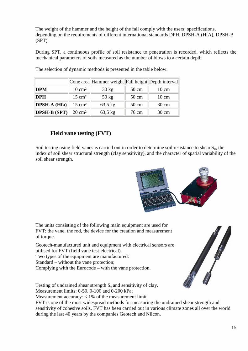
Soil testing using field vanes is carried out in order to determine soil resistance to shear Su, the index of soil shear structural strength (clay sensitivity), and the character of spatial variability of the soil shear strength.
The units consisting of the following main equipment are used for FVT: the vane, the rod, the device for the creation and measurement of torque.
Geotech-manufactured unit and equipment with electrical sensors are utilised for FVT (field vane test-electrical). Two types of the equipment are manufactured: Standard – without the vane protection; Complying with the Eurocode – with the vane protection.
Testing of undrained shear strength Su and sensitivity of clay. Measurement limits: 0-50, 0-100 and 0-200 kPa; Measurement accuracy: < 1% of the measurement limit. FVT is one of the most widespread methods for measuring the undrained shear strength and sensitivity of cohesive soils. FVT has been carried out in various climate zones all over the world during the last 40 years by the companies Geotech and Nilcon.
Cone area Hammer weight Fall height Depth interval
DPM 10 cm² 30 kg 50 cm 10 cm
DPH 15 cm² 50 kg 50 cm 10 cm
DPSH-A (Hfa) 15 cm² 63,5 kg 50 cm 30 cm
DPSH-B (SPT) 20 cm² 63,5 kg 76 cm 30 cm

16
There are two versions of the equipment: with the vane protection in accordance with the Eurocode and without protection. Both versions of the equipment are electrical; its purpose is the measurement and recording of torque and cohesion. The vane is introduced in soil using an instrument mounted on the push-in (penetration) unit. In the standard version, the string to which new rods are added goes through the recording device, i.e. the instrumented head need not be detached to carry out each measurement. In the model complying with the Eurocode, everything depends on the testing interval and the stroke length, where the instrument must not be remounted. Both the vane in the protection case and rods of the penetration string could be introduced in soil with the device complying with the Eurocode. The electrical vane complying with the Eurocode is supplied together with the protection case, the purpose of which is to remove most of the friction on the side surface and the protection of the vane during the penetration into the soil. The disconnector is mounted between the rod string and the vane to measure the friction between the rod string and the protection case. The standard field vane equipment does not have a protection case. A disconnector similar to the Eurocode model is used to measure friction on the side surface of the rod string. The applied torque, measured by a load sensor, and the angle of rotation are recorded after each 0.5 degrees in the PC. The configuration of the recorded dependence ensures the control of the correctness of the execution of the test and the nature of the soil. The torque for the rotation of the rod column must be recorded first of all, and, subsequently, the full torque for the rotation of the rod column and the vane until the moment of the soil destruction. The difference between those values is utilised for the calculation of the soil shear strength. The dependences are stored in individual files for each test. Using the Geotech’s software (Vane-Log) for the data acquisition, the soil shear strength is determined; there is also the possibility of the calculation of the rod friction and the determination of the dependence of the change of torque on the vane turning angle.
The vane is manufactured from high-quality chrome-nickel steel and has been designed specifically for pushing into soils with as little disturbance as possible. The standard vane model has a wedge-shaped cusp in the lower part to improve the penetration. Technical parameters of the model complying with the Eurocode: The vane (Ø x h, range): 65 x 130 mm, 200 kPa; The blade type: rectangular on two sides; The protective shell of the vane: external Ø75, length 820 mm; The protection case: external Ø42 mm; The string rods: Ø22 x 1000 mm; The disconnector: 15° clockwise. Technical parameters of the standard model: The vane (Ø x h, range: 50 x 110 mm, 200 kPa;

17
65 x 130 mm,100 kPa; 80 x 172 mm, 50 kPa; The blade type: rectangular on two sides; The string rods: Ø22 x 1000 mm; The disconnector: 15° clockwise. The recording instrument: Dimensions LxWxH: 360 x 210 x 110 + connector, 140 mm Measurement limit: 100 N x m Measurement accuracy: < 1 % of the measurement limit The clamp: distributed along the axis length, 125 and 85 mm on each side.
Determination of physical and mechanical properties of soils in situ using
Pocket Vane (P-vane)
The pocket vane is used for the preliminary evaluation of the undrained shear strength Su and the consistency of the clayey soils. Clayey water-saturated soils with the undisturbed structure from soft to stiff are the sphere of the use of the device. The device - Model 16-T0175/A is a device equipped with a spring, with a blade tip and the scale calibrated in N/cm2. Besides the main tip, the device also has two extra removable ones. The selection of the tip type depends on the soil consistency. The dial of the Pocket Vane is marked for the normal tip, from 0 to 10 N/cm2, which is equivalent to the determination of Su within the range from 0 to 100 kPa. In order to test a sample with the undisturbed structure, a smooth clean surface is prepared, with the diameter of at least 2.5 cm. Then the Pocket Vane is carefully pushed into the soil to the depth of the tip blade. By the effort of fingers, constant vertical pressure is provided, and a slow turning of the head is executed during 5-10 seconds until the failure of the soil occurs. The readings of the indicator at the moment of the failure of the soil provide the value of shear strength SU, which corresponds to undrained testing in the triaxial testing equipment. The readings are read out. The indicator returns to zero, and the device is ready for work once again. The average measured reading (out of 3) of the device in N/cm2 is transformed into kilo Pascals (kPa) using the conversion factor for the relevant tip.
Based on the obtained evaluated values of the undrained shear strength, preliminary evaluation of the soil consistency is made within the framework of the classification of GOST 25100-95, ASTM or BS5930.

18
The measurement results are accumulated in the form of tables and are produced in accordance with the approved requirements for the preparation of the field report documentationии.
Determination of physical and mechanical properties of soils in situ using Pocket Penetrometer (P-penetrometer)
The Pocket Penetrometer 16-T0171 manufactured by “Controls” is used for the preliminary evaluation of the physical and mechanical properties of soils, including the consistency of the clayey soils and undrained shear strength Su. It ensures quick determination of the above-mentioned physical and mechanical properties right after the extraction of the sample from the sampler.
The Pocket Penetrometer 16-T0171, Controls
The utilised device - Model 16-Т0171 represents two telescopically connected cylinders with an internal compression spring. The tip of the internal cylinder (marked by cut) is for pushing into the soil sample. The force of the resistance to penetration is read from the indicator scale of the device, calibrated in kg/cm2. That model can be used both in the laboratory and field conditions for working with soils with the undrained shear strength from 0 to 4.5 kg/cm2. In order to execute the testing of a sample with the undisturbed structure, a smooth clean horizontal surface is prepared. Subsequently the tip of the device is carefully pushed into the soil until the cut on the tip is reached; during that process, by the effort of fingers, constant vertical pressure and vertical position of the device are provided. Based on the obtained evaluated values of the undrained shear strength, preliminary evaluation of the soil consistency is made within the framework of the classification of GOST 25100-95, ASTM or BS5930
Laboratory testing of soils for the determination of their physical and mechanical properties
The laboratory investigations envisage the determination of the composition and physical and mechanical properties of soils using the nomenclature, which ensures the execution of the necessary geotechnical and engineering calculations. Descriptions of the received soil samples are prepared before the initiation of the tests.
The laboratory testing is carried out in accordance with BS 1377. The existing laboratory equipment and devices ensure the determination of all indices of the soil propertied, which are mentioned in the “Specification for geotechnical investigations”.
The following equipment and devices are available for the testing and analysis of the
parameters of the obtained soil samples in the onshore laboratory

19
Type of test Equipment Device model
Soil density, moisture content
Scale - Oven 225 (40-200°C) Scale with balance beam - Top Pan Balance ADP-3100 g, resolution 0.01g
WF-61020 WF-60046
Density of soil particles
Scale -Top Pan Balance ADP-360g, resolution 0.01g Vacuum pump 45 l/min., 240 V/50 Hz Refrigerated Circular 240V/50 Hz Vacuum dessicator Ø 250 mm with lid Pycnometer 100 ml with thermometer (0-30)°C
WF-60044 WF-33312 Julabo F34 WF-32926
Atterberg limits Motorised device for the determination of yield strength in accordance with BS-1377
WF-21520
Grain size composition (sieve, hydrometer)
Fabric wire net (BS-410) Ø 200 mm, set of sieves (63 micrometres – 75 mm) Sieving machine Hydrometer for soils, calibrated from 0.995 to 1,030 q/ml in accordance with BS-1377 Calibrated glass measuring cylinder with the volume 1000 ml Steam bath with temperature controller
WF-62020 WF-23860
Carbonate content
Calcimeter, burette for calcimeter (volume 250 ml) Fijkelkamp 0853: 085301
Shear testing Direct shear apparatus WF
Triaxial testing (HH)
Compression testing apparatus „TRISTAR” - 5000 kg The working chamber, max. pressure 1700 kPa; Force in the chamber 5 kN Pressure sensor 1000 kPa; burette 50 ml; pressure gauge 12 bar; digital indicator (50 ml); Nold de-airing system; Air compressor; Vacuum pump
WF

20
Engineering-geophysical operations
Engineering-geophysical operations are an integral part of geotechnical surveys during all stages of their execution (the project, working documentation). The engineering-geophysical surveys supplement the net of geotechnical drilling, improving the information content of geotechnical investigations. The main methods of engineering-geophysical surveys are as follows: seismic, electrical surveys and georadar. Seismic reflection method – Mini-CDP The seismic reflection method in its modification – common depth point (CDP) ensures the maximum depth out of all methods utilised in shallow seismic. The system of observations envisages rather high density of shotpoints of elastic waves and signal reception points per line unit with the purpose of ensuring multiple coverage during the tracking of the reflector boundaries. The technology of the operations is quite labour-consuming, but it ensures the acquisition of most reliable information about the geometry of boundaries of the subdivision of physical properties in the investigated space, which are associated not only with layering, but also with possible discontinuities of rocks due to tectonic movements.
In many cases, the use of most simple and environment-friendly surface sources of elastic waves of the falling weight type (Fig. 2) allows to obtain quite strong reflections from boundaries at the depth of 500-600 m. The usual task during engineering surveys is to investigate the properties of the soil massif and the bedrock to the depth 40-50 m. Sometimes there are specific tasks, which require the increase of the depth to 150-200 m.
Fig.1 Time section for the line Rost.3.03. The Verhne-Kamskoe deposit of potassium salt, July 2003. The line was shot using a 40-kg falling weight with accumulation of 4 impacts. The height of hoisting the weight – 3 m. The shotpoint interval along the line – 8 m, the interval of the receiver channels – 8 m, central spread, 48 channels, the length of the receiver base – 384 m. Receiver groups – 5 geophones manufactured by OYO per channel, group base – 16 m. The recording equipment –the seismic station IS-128-01 (Interseis, Latvia), the sampling rate – 0.5 ms. Filtering at reception – 14/500 Hz.
Elevation mark of a relief, m
Statistical correction for source position, ms
Time cross section of CDP
terrigenous-carbonate formation salino-marlaceous formation transitive geological unit Pokrovsk stone salt top of carnallite zone bottom of productive formation bottom of all salt formation

21
Fig.2 Excitation of elastic oscillations using the surface source of the “falling weight” type (the weight - 36 kg).
SEISMIC ACOUSTIC INVESTIGATIONS IN BOREHOLES During seismic acoustic investigations in water-filled geotechnical boreholes, the reception of oscillations is executed using a hydrophone probe, which is lowered into the borehole. The excitation of oscillations is carried out either on the surface or in an adjacent working – mine or well. In order to obtain a spatial image of the distribution of physical properties of the investigated massif, several lines are used, which form an areal grid of shotpoints on the surface of the massif (Fig. 3). That allowed to carry out the survey using the so-called “semi-topographic” scheme with the investigation of a pyramid volume around the borehole under investigation.
Fig.3 Scheme of line positions with initiation points on the surface

22
Fig.4 Scheme of positions of initiation points in a shaft and the ray scheme during the observations using the method of interwell sounding (seismic tomography)
The records, obtained using the method of seismic tomography, allow to obtain the most detailed and reliable images of the distribution of physical properties of the investigated massif in the plane of the ray propagation between two workings due to the highest and uniform density of seismic rays (Fig. 4).. EQUIPMENT
SEISMIC ACOUSTIC RECORDERS IS128-02, IS128-03
Seismic acoustic recorder IS128-02 Seismic acoustic recorder IS128-03
The purpose
• seismic acoustic investigations with the frequency range from 2 Hz up to 8 kHz, • profiling at the ground surface and in shallow boreholes, • investigations of the upper part of geological section using refracted, reflected and surface
wave techniques, • geotechnical investigations,

23
• control of the technical condition and geological and geophysical monitoring of onshore and offshore structures,
• acoustic investigations of the road pavement, substructures and foundations, • offshore shallow seismic acoustic surveys and continuous subbottom profiling in single-
channel and multi-channel modes.
During operations with relatively weak power sources of the initiation of seismic pulses, the recorder provides the stacking of weak signals. The stacking of seismic acoustic signals using hardware is carried out before the record transmission to the long duration memory on a hard disk. Remote 16- channel distributed modules with low power consumption can be connected to the central module via two-wire high-speed USB-RS485 interface or WiFi radio interface. Configuration System of synchronisation of initiation and reception: • by forming the initiation pulse and its transmission to the seismic source, • reception of the synchronisation pulse from an external source. The recorder is capable of simple programme interactive diagnostics, including the device, which forms test signals with analogue output and which facilitates the control of the workability of the equipment, search and elimination of failures in the field conditions. The design of the recorder allows its use in the conditions of high dust content and humidity. The equipment retains its performance capacity at the temperature of the surrounding air from 0 to +400C, relative humidity of up to 98% at +250C and relative pressure (750 +/-30) mmHg. The service programme ensures the stacking of signals, storage in the file and imaging of data on the monitor screen. The programme is also capable of simple record pre-processing procedures immediately after the acquisition, as well as the spectral analysis of the records. The set of procedures also incorporates an analysis of amplitude-frequency characteristics of seismic signals in different recording modes based on test records. During the offshore operations, for the geodetic positioning of data, the GPS receiver is connected to the COM port of the master computer, and continuous recording of co-ordinates in the seismic line label is executed. The recorder has been designed for the utilisation, primarily, in hardly accessible terrain, in geotechnical boreholes, inside industrial facilities and underground workings, as a distributed system for the acquisition of seismic acoustic data. It has been designed based on the latest electronic components, and has quite high indicators as regards energy consumption, weight, dimensions and simplicity of communication lines.
The existence of several autonomous remote modules in the recorder system allows to use sufficiently flexible linear, areal and spatial observation systems. As an option, two or more remote modules can be placed within the case of the central module; in that case, the recorder represents a usual geotechnical seismic station with the number of channels from 16 to 64.

24
Record obtained using a percussion source 8 kHz using Placement of a remote module in a shock- four modules, sampling rate 200 mcs, proof and waterproof case OtterBox CQ5000 channel step 2 m. The power supply of the central module is from a DC source 9-18 V, usually from an external lead-acid battery 12-17 A/hr. The remote modules have built-in lithium batteries, 7.4 V, 2A/hr. The current consumed by a remote module in the operational mode (with the buffer disabled) does not exceed 250 mA, comprising 350 mA with the operational buffer. The activation of the buffer increases the input resistivity, which allows to increase the sensitivity of the seismic channel many-fold. When the cable of the interface RS485 is disabled, the module enters the “sleep” mode with the consumption of maximum 30 mcA. When the minimum permissible voltage in the accumulator is reached, the module is switched-off automatically. Main technical parameters 1) Number of utilised modules (is set by the user) 1-16 2) Number of channels of the remote module 16 3) Input resistivity (is set by the user) 0.001-100 MOhm 4) Frequency range at -3 dB 2-8000 Hz 5) Dynamic range at dt=1ms 130 dB 6) Bit depth conversion, delta/stigma 24 Bit 7) Amplitude sampling period 0.03 - 4.0 ms 8) Stacking, 32 bit output code 256 9) Initial amplifier gain 6, 12, 18, 24, 30, 36 dB 10) Frequency of initiation pulses up to 2 per sec. 11) Anti-alias filter bandwidth 125 - 8000 Hz 12) Low-cut filter 36 dB/octave 13) Rejection filter 50, 100, 150 Hz, 48 dB 14) Counts per channel (optional) 192/16384 15) Noise level at input at 1 ms 1.3 mcV
Ок
Сервисна
Flowchart of data collection and processing
Starting geophone
Synchronization pulse
Central module
Geophones Geophones Remote module

25
16) Input signal range +/- 5 V 17) Crosstalk ratio at 100 Hz < -100 dB 18) Suppression of equiphase noise >110 dB 19) The format of output code integers 32 digits 20) Primary power source 12 V 21) Host processor PCM-5820 22) Data transmission USB, RS485 23) Random access memory 256 MB 24) HDD 30 GB 25) Display LCD TFT 12,3”, SVGA 800x600 26) The keyboard: membrane, protected 56 keys, IBM AT 27) Degree of environmental protection b IP65 28) GPS Protocol NMEA-183 29) Dimensions of the host module 378х330х178 mm 30) Weight of the host module 8.0 kg 31) Dimensions of the remote module 171х121х55 mm 32) Weight of the remote module 1.1 kg 33) Ambient temperature: host module 0°С -+40°С remote module -20°С -+50°С
Connection оf geophone sections to the remote Interface and synchronisation module
module on the line The connection of remote modules to a usual laptop PC is the most convenient as regards the technology of field operations and noise suppression in the recorded signals; it is executed via a USB port, using a specialised high-frequency convertor USB-RS485 and block of synchronisation of records. In that case, separate geophone cables are connected directly to the remote modules on a seismic line, which are joined to each other and connected to the interface module via a two-wire digital line. Due to that, the impact of the electromagnetic noise level on the signal and extension cables is greatly reduced. The data transmission from the interface module to the PC is executed either via the two-wire line or by radio, via a WiFi interface, if the communication distance does not exceed 100-120 m. Software of data acquisition and processing

26
The service programme works in the environment of the operation system Windows98/XP. The test module of the programme allows to check up the main technical parameters of seismic recording channels, to provide examination channel-by-channel and calculation of statistical parameters of the records, and to carry out the spectral analysis of the records.
The set of window menus makes it possible for the operator to set the parameters of recording and receiver geometry easily and graphically.
Windows of settings of recording and receiver geometry
A synthetic seismogram, obtained after the transmission of data from several remote modules is shown in a working window of the acquisition programme, as well as the level of charge in the built-in batteries of the remote modules, the number of the current initiation in the stacking series, the current record number and the process of the signal transmission. Using the scroll line, long records with the selected degree of detail could be seen.

27
GEORADAR SURVEYS
It is possible to use georadar for simpler geotechnical investigations, for example, during surveys for the road construction, determination of the condition of pavement, when it is necessary to investigate the properties of the soil massif to the depth of maximum 20-30 m. The georadar is a geophysical instrument for fast soil profiling. The principle of the georadar action is based on the emission of very wide band pulses of the metre and decimetre range of the electromagnetic waves and the reception of signals reflected from objects or inhomogeneities, which have dielectric permeability or conductivity that is different from that of the environment. The reflected signal is transformed into the digital format and is imaged on the display. The PC allows to see the obtained results and to execute the necessary processing procedures. In order to obtain data from different depth, aerial blocks are used, working using different frequencies. The general rule is as follows: the lower is the working frequency of the aerial, the greater is the depth of the signal penetration, but the resolution decreases and vice versa. The following problems could be solved using the georadar. During the stage and design of highways Investigations of the geotechnical conditions at sites subjected to deformations:
• determination of the depth of groundwater and occurrence of vadose water; • mapping of the top of the rock foundation; • identification of zones of occurrence of specific soils (peat, silt, salted soils etc.; • determination of the position of the top of permafrost; • investigation of taliks and cryopegs; • determination of dynamics of cryological phenomena (zones of seasonally frozen soils); • mapping of underground communications.
Investigations of hazardous geotechnical processes: • landslides; • quicksand; • karst phenomena.
During the stage of exploitation and reconstruction of road pavements
Control of the compliance of the pavement with the design documentation. Investigation of the condition of the construction layers of the pavement. • determination of the thickness of the construction layers of the pavement;
identification of subsidence; • identification of failed and flooded areas.

28
Composition of equipment and scheme of utilisation of georadar:
Examples of investigations of roads and runways
Georadar “OKO”
The "OKO-2" georadars are the recognised leaders among similar Russian products. The instruments are certified and patented. Based on their technical parameters, the "ОКО-2" georadars are on the level of georadars manufactured by the leading world manufacturers, exceeding some parameters of similar foreign equipment. The set of the "ОКО-2" georadar incorporates the basic set and the aerial blocks, which are selected depending on the task. The aerial blocks are exchangeable. Using an aerial block with a lower
Hanger with laptop
Power supplay unit 9/12
Control unit
Electrical cable
Mono ski
Aerial block
Path meter
Optical transformer
Optical cable
Handle
distance along a profile, m
distance along a profile, m
r
efle
ctio
n ar
rival
tim
e, n
s
Dep
th, m
Clay
Sand Peat
Sand-Silt variation

29
frequency, it is possible to increase the depth of investigations, but, if it is necessary to achieve a high degree of detail in the investigations of the top part of the section, high-frequency aerial blocks should be used. A combination of the aerial blocks with different frequencies is optimal. Both shielded and unshielded aerial blocks are used in the "ОКО-2" georadars. The "OKO-2" georadar has full optical decoupling as regards the signal and information chains, which improves the performance of the instrument under complex conditions. The "OKO-2" georadar has intelligent shielded aerial blocks for different frequencies, equipped with a microprocessor for pre-processing the acquired information. All the aerial blocks of the "OKO-2" georadar can operate with three types of motion sensors (wheel, coil, automobile sensor). The software of the georadar supports the operation of the georadar in conjunction with GPS receivers. The processed data are output in different formats, such as SEG-Y, CSV, HTML, EXCEL, supported by standard software packages (MATLAB, AUTOCAD etc.). There is a specialised microprocessor processing block for the operation in adverse weather conditions (rain, frost, bright sun etc.); it allows to operate at the temperature from - 20° to + 50°C; the ABDL aerial block “Triton” (flexible aerial) allows to carry out surveys in the tundra, forest, on water and underwater. The control block provides the control of all operating modes of the georadar, executes pre-processing of the acquired data and transforms the signal received from the aerial block into standard signals for the laptop (Ethernet, USB). The aerial blocks are used of the "ОКО-2" georadar consist of the receiver and the transmitter blocks. The aerial blocks are subdivided into two categories – those with the optical decoupling as regards the signal and information chains and those without it. In the aerial blocks with the optical decoupling, the receiver and the transmitter blocks are powered by separate power sources, and an optical cable is used for the transmission of the signal from the path meter from the receiver block to the transmitter block. In the aerial blocks without the optical decoupling, the power is provided through an interface cable from the control block. All the aerial blocks are dust- and waterproof. The power consumption is approximately 7-8 W.
ELECTROMETRY
The data of multichannel electrical profiling using the resistivity sounding (electrical tomography) allow to evaluate, predominantly, the character and degree of the saturation of the soil massif by fluid. It is possible to provide a more complete evaluation of the condition of the soil massif as a foundation for the structure under design in conjunction with the data of seismic using different types of waves.
REPORTS
Field reports are presented after the completion of field operations. They contain information about the technology and volume of the completed operations. Initial data are submitted for consideration (sections, diagrams, columns etc.). Preliminary reports are submitted after the completion of field operations. They contain preliminary results of data processing and conclusions about the geotechnical conditions at the investigated site.

30
The Technical Report is submitted after the completion of geotechnical investigations. It contains final results of investigations, results of calculations, necessary for the development of the project aimed at the construction of an object.