methods of measuring the mechanical behavior of … · methods of measuring the mechanical behavior...
TRANSCRIPT

NRL Memorandum Report 2459
Methods of Measuringthe Mechanical Behavior of Wire Rope
D. A. MILBURN AND N..J. RENDLER
Ocean Engineering BratnchSOc.an Techntology Division
July 1972
7 of
NATIONAL TECHNICALINFORMATION SERVICE
NAVAL RESEARCH LABORATORYWashington, D.C.
Approved for public release: distribution unlimited.
UNCLASSIFIEDSet'clrtly C|lassfedtion
DOCUMENT CONTROL DATA - R & DISt'.trlty CIA%.s•tI( ofteoton of ttlek, blud)," t o 1hf /ract .,1and trldexit ,.nnotartion nott ,4'zI eti't'-d when the i overall rptyprt s% (. h h sif<t )
I OII1GINA TItNG ACTIoVITY (Corpllolte altdl't) IZo. nCPOlI ýCCUIII TV CLASSI FI C. IION
Naval Research Laboratory UNCLASSIFIED
Washington, D.C. 20390 Sb GROuP
oI :pORT TITLE.
MI&THODS OF MEASURING THE MECHANICAL BEHAVIOR OF WIRE ROPE
4 0.SCFtII ' ýlIV -OTES (7•ypO of rcptrt .od inclu..#,e d.ates;
A final report on one phase of the problem; work is continuing on other phases."5 AU T#1O• $SI (1',r. I tI nuo , middle initil, ln.• il.onie,)
D.A. Milburn, and N.J. Rendler
SRF-PORr DA re li. TOTAL NO OF r"ACES lb. NO O 1 " FrS
July 1972 28 6Sit CC0N TRACT OR Llt/'1 IhO 1n'. OrIGINA TOn'S fnL ORT ,.UMOLPIS)
NRL Problem F02-23.S. ,,,oj•, NO NRL Memorandum Report 2459
RR023-03-45-5806V .h OT0ER i-L-PORT NOIS) Atlltyh'ritnnibe•, thatn.wt S. I,, :n,,i
(tII, rep ",t)
IT T)ISTRIOUTION STATEMENT
Approved for public release; distributi3n unlimited.
II SUP I'CM i( NtAiiY NOrES 1.' 5TO #'I';Oi1I IG Y' L' I ,I.y A' * Vr ,
Department of the Navy
Office of Naval Research
Arlington, Virginia 22217I AE]STRACT
Techniques were developed for the accurate measurement of load, elongationand torque generated in a wire rope during an axial static mode of tensile loading.Se'.ction of parameter measurement systems was based upon the unique response ofwire rope to axial loads. A tension-torque transducer was designed for thesimultaneous but independent measurement of applied load and induced torque. Anelectro-optical tracking system was adapted for use as a rope extensometer.Measurement of elongction is performed continuously and directly upon a section ofthe rope. Furthermore, expendable electro-optical-targets permit extension %,easure-ments up to and including specimen rupture. Both measurement systems are capableof an accuracy of 1%.
Laboratory investigations revealed a correlation between rope specimen prepara-tion techniques and final accuracy of the measured rope parameters. Methods weredeveloped for alignment and termination of rope specimens to insure a normal sharingof the test load by wire and strand components of the rope.
An illustration of specimen preparation and a demonstration of the instrumen-tation is provided through measurement of the load-strain and torque-load behaviorof a 3/4-inch-diameter, type 304 stainless steul wire rope of 6 X 19 (7 X 7 IWRC)
Warrington construction.
4/ ; .. -- " __ _ _ __ _ _ _
FORM-95- UNCIASSIFIED
Z,]" 0102.014.-6600

UNCLASSIFIEDSecurity Classification
14. LINK A LINK 8 LINK CKEY WORDS I
Wire rope
ROLE WT ROLE WT ROLE WT
Electri-mechanical cableSynthetic ropeTesting of wire ropeElectro-optical tracking techniques
DD ,'°:,",.1473 (BACK) 26 UNCLASSIFIED(PAGE 2) Security Classification

CONTENTS
Abstract iiProblem StatusAuthorization
ii
INI .ODUCTION 1
WIRE ROPEI
TEST SPECIMEN PREPARATION 2
PRELIMINARY ROPE TEST 3
INSTRUMENTATION 4
Load-Torque Measuring System 5
Electro-Optical Extensometer 5
MECHANICAL BEHAVIOR OF A WIRE ROPE 6
CONCLUDING REMARKS 7
AC KNOWLEDGEMENT 8
REFERENCES 9
I-/.

ABSTRACT
Techniques were developed for the accurate measurement of load,elongation and torque generated in a wire rope during an axial staticmode of tensile loading. Selection of parameter measurement systemswas based upon the unique response of wire rope to axial loads, Atension-torque transducer was designed for the simultaneous bu:independent measurement of applied load and induced torque. Arelectro-optical tracking system was adapted for use as a rope etenso-meter. Measurement of elongation is performed continuously anddirectly upon a section of the rope. Furthermore, expendable electro-optical-targets permit extension measurements up to and includingspecimen rupture. Both measurement systems are capable of an accuracyof 1%.
Laboratory investigations revealed a currelation between ropespecimen preparation techniques and final accuracy of the measuredrope parameters. Methods were developed for alignment and terminationof rope specimens to insure a normal sharing of the test load by wireand strand components of the rope.
An illustration of specimen preparation and a demonstration ofthe instrumentation is provided through measurement of the load-strainand torque-load behavior of a 3/4-inch-diameter, type 304 stainlesssteel wire rope of 6 X 19 (7 X 7 IWRC) Warrington construction,
PROBLEM STATUS
This is a final report on this phase of the problem; work iscontinuing in other phases.
AUTHORIZATION
NRL Problem 84F02-23
Project RR023-03-45-5806
ii

METHODS OF MEASURING THE MECHANICALBEHAVIOR OF WIRE ROPE
INTRODUCTION
Recent oceanographic research utilizing marine structures hasimposed a close dimensional tolerance upon its wire rope components.For example, the specifications being written for marine experimentsupport platforms, in water depths of four to five miles, requires anoperational position accuracy of less than 1. of cable length. Exist-ing wire rope data is inadequate for this design trend. The currentstudy is concerned with the precise measurement of basic wire ropecharacteristics needed in marine technology.
Most frequently a marine cable must endure an axial tensile forceupon which is superimposed a variable amplitude, low frequency load.Response of this intricate construction of wires and strands to anexternal load is unlike that of any other structural member. Forexample, the construction of most wire ropes is such that torque isgenerated when the rope is loaded. Elastic behavior of wire rope isalso unique in that it consists of both structural stretch and elonga-tion of individual wires. "On-the-shelf" measurement techniquesavailable for testing materials do not directly -ply to the accuratemeasurement of these rope parameters.
The following report describes the test procedures and instrumen-tation developed for an accurate laboratory measure of rope behaviorunder static and dynamic axial modes of loading.
WIRE ROPE
An understanding of rope constructional form and the manner inwhich this form relates to the rope's behavjior when axially loaded,was a necessary prerequisite to this study. The wires in a wire ropeare arranged in a centric symmetry. They are woven together intostrands, and several strands into ropes according to specific laypatterns. Liteyally hundreds of rope constructions are available tothe user. Certain general constructional features, however, arecommon to a number of rope types and it is possible to describe theseas they appear in a specific construction. A 3/4-inch-diameter wirerope frequently employed as a support cable in NOMAD moored Luoysystems (I) was selected for this discussion. The rope is shown inFig. 1. Caption nomenclature, Fig. 1, indicates a rope having six

outer strands of 19 wires per strand. Note that the six outer strandsare helically wound about an independent wire rope core (IWRC) whichitself has seven strands of seven wires per strand. The cross-sectional view .f the rope depicts the Warrington construction, i.e.wire of a different diameter is present in the outer wire layer ofrope strands.
This 3/4-inch-diameter rope has two salient constructionalfeatures that are important. First, outer strands of the rope andIWRC are formed in a right regular lay. In this pattern wires olthe strand wind to the left while strands themselves twist to theright in forming the rope. Finally, the rope is preformed; individualwires and strands were pre-shaped prior to assembly. Both of these
features contribute to a mechanical stabilization of the rope. Inregular lay construction, wires are tucked securely under the strands
and the rope is less likely to kink and antwist during service. Thissame behavior is further impeded by the preform process.
Mechanical response of wire rope to axial load depends upon itsconstruction and the material properties of the wires. An axial loadimposed on the rope generates three types of force. There is atensile force on each wire (2), a radial force which presses wiresand strands against their respective cores (3) and tangential forces(4). The tangential forces produce torque, which tries to unlay thehelically wrapped strands. Wire rope elongation is particularlycomplex. It consists of both structural stretch and elongation ofindividual wires and strands. Structural stretch is a consequence oflengthening of the rope lay, compression of the strands and IWRC, andan adjustment of wires and strands to the load.
TEST SPECIMEN PREPARATION
In preparing for an accurate measurement of wire rope behavior,
certain precautions regarding experimental procedures must be observed.Procedures that permit the full transfer of test load to the rope,without the introduction of abnormal wire stresses, are essential. Afew precautions tbat will asnist in meeting this ideal conditioninclude:
1. The normal position of wires and strands during cutting,terminating and testing of the rope must be preserved.
2. The pre-test configuration of the rope should be rela-tively straight and the rope in near-perfect axialalignment with its terminators.
3. The free-length of the test section must be sufficientlygreat so as to render any small constructional distor-tions, introduced during termination, ineffective.
2'i

Commercial open-end spelter sockets were selected for terminatingwire ropes because they'permit t0E full rope strength to be developed.A schematic cross-sectional view of a terminated wire rope is shownin Fig. 2. The molten zinc should completely fill the socket basketand provide optimum penetration into the wire interstices. Penetra-tion of zinc into the wire transition zone, wherein the "broomed-out"wires resume the normal rope configuration, is desirable. Incompletezinc penetration in this area can result in abnormal wire stressesand pull-out of the wires. As a consequence, in a rope rupture test,wires will prematurely fail at or in the rope socket. Furthermore,rotational displacement of wires within the sockets would produceerrors in torque measurements when, in later tests, a torque trans-ducer would be placed in series with the rope.
The procedures given in Ref. 5 were followed in regard to seizingand "brooming-out" of the wires, however, cleaning procedures werechanged. Broomed rope ends were ultrasonically cleaned in freshsolutions of trichloroethylene. After air drying, the broomed endswere immersed in a bath of solder flux to insure wetting and a goodbond between the zinc and wires of the rope. The cleaned, "broomed-out" wires were drawn together with a special clamp so that the socketcould be forced down over them. Next, the assembled rope and socketwas mounted in the alignment fixture, Fig. 3. This device wasdesigned to hold the rope and socket in near-perfect axial alignment.The socket was preheated to 160OF to expel moisture and prevent themolten zinc from solidifying before completely filling the Lower endof the basket. An alloy of 10% tin and 90% high purity zinc heated to950°F was then poured into the large end of the socket.
The foregoing procedures enhanced the flow of zinc. For purposesof inspection, terminators were disassembled by cutting the rope atthe socket ends and pressing-out the remaining core from the socketbaskets. An actual rope-socket-core is shown in Fig. 4. The extentof metal flow was sufficient to engulf the rope throughout the wiretransition zone. Top view of the core, Fig. 4, presents a near-perfect cross-sectional view of the noimal rope constructioin. Forpurposes of comparison, Fig. 5 depicts two poorly terminatcd socket-coves.
PRELIMINARY ROPE TEST
In order to establish criteria for the wire rope instrumentation,it was necessary to conduct a rope tensile test. The methods andtechniques employed during this effort were only preliminary in nature.
The primary purpose of this investigation was to compare twodifferent methods of measuring strain in a rope. A first method,commonly employed, involved the measurement of machine cruss-headdisplacement while the other technique utilized an instrument formanually measuring extension over a marked length of rope. Figure 6
3

illustrates the experimental set-up. The 3/4-inch-diameter wire ropemounted in the 60,000 lb capacity test machine is of the type pre-viously described L ' used for all tests in thio report. A 30-inchlength of this rope w-. .eized and terminated 4n accordance with theprocedures mentioned earlier. After the specimen was asp.mbled in thetest machine, two gage marks were scribed on the rope circumferencein a plane normal to its axis. The distance between gage marks wasapproximately 24 inches. During the test, rope elongation wasmonitored by means of alignment stand indices and rope gage marks. Ameasur.e of the index spacing was accomplished with the vernier calipersshown on the indexing stand, Fig. 6. Rope extension measurements werecoordinated with load indicator readings in order to provide data fora load-strain plot. A continuous graph of load-strain behavior wassimultaneously obtained from the t2st machine's load-displacementrecorder. Initial rope length for the latter strain measurement wasbased upon the length of rope between terminators.
The two representations of the rope's load-s.zain behavior aregiven in Fig. 7. Curve A more accurately depicts the actual behaviorof the rope under tensile loading since strain readings were derivedfrom manual elongation measurements over a gage length on the rope.Curve B illustrates the extent to which error in machine head displace-rnent readings can contribute to an erroneous load-strain response. Forexample, the strain error at 40,000 lb of load is about0 50% of actualrope strain.
Strain readings for Curbs B contain error from a number ofsources. Because strain was based upon displacement of the machinecrosshead, it must therefore include the effect of elastic deformationsin machine columns, crossheads, rope sockets and socket adaptors aswell as extension in the rope. Deformation of the foregoing load traincomponents during the test was small, however; with the exception ofzinc-pull-out from the sockets. Localized irregularities in curve Bare evidence of this creep effect. These irregularities were intro-duced when loading was interrupted to allow time for manual measurementof rope extension. As a safety precaution manually derived strainreadings for curve A are aot given for test loads near specimen rupture.A comparison of the two test results indicates that an extensometerthat can achieve continuous readings of extensions, over a rope gagelength, up to and including specimen rupture would be advantageous.
INSTRUMENTATION
Transducers that can accurately measure load, elongation andtorque induced in a wire rope were the primary objective of thisstudy. The tension and torque instrumentation was combined into asingle unit by utilizing the strain gage techniques described inRef. 6. An electro-optical tracking system was adapted for use as arope extensometer. Measurement of elongation is performed continuously
4

and directly upon a section of the rope. Furthermore, expendableoptical-targets permit extension measurements up to and includingspecimen rupture. Principles of operation and implementation of thesemeasuring systems are described in the following paragraphs.
Load-Torque Measuring System
The tension-torque transducer shown in Fig. 8 is designed for thesimultaneous but independent measurement of applied load and torquegenerated in a wire rope. Machined from high strength maraging steel,the transducer is designed for maximum combined working loads of50,00) lb tension and 500 ft-lb of torque. In terms of rope specimensize, it will accomodate most 1/4- to 7/8-inch-diameter wire ropesloaded to failure. The unit is instrumented with two separate sets of
L four strain gages. Each set of gages is utilized in a four-armWheatstone bridge circuit for the independent measurement of tensile"and torque loads.
Mechanical calibratioy of the transducer was accomplished with theCalibrator, also shown in Fig. 8. The device was mounted in a60,000 lb capacity universal test machine for application of knownaxial loads. Torque calibration was performed by disengaging theCalibrator's lower threaded adaptor from the test machine and utilizingthe two bolts as force ;ransducers. Each bolt was previously instru-mented with strain gages and separately calibrated for the measurementof bolt load. Bolt forces were applied in a plane perpendicular to theaxis of the transducer and at a known distance from its axial center-line to produce the required torsional moments. Transducer calibrationdata revealed that the axial load and torque bridge circuits hadnegligible response to torque and axial load respectively. Furthermore,the accuracy of this dual measuring system was determined to be 1%.
Electro-Optical Extensometer
The electro-optical tracking system in Fig. 9 consists of twooptical heads with control units, a differential amplifier, and twotargets which are rigidly attached to the rope. Mounted on eachoptical heal is a lens system that must be focused on the opticaldiscontinuity created by the back-lighted lucite panel and the upperedge of the target. A special photomultiplier tube within the opticalhead converts this optical image into an identical electron 'mage.Electrical signals from the optical head control unit causes thephotomultiplier tube to examine this electron image. Any displacementof a rope target is evidenced by a sharp change in photomultipliertube voltage output and is directly proportional to target displace-ment. A differential amplifier subtracts the two optical head voltagesignals and thus tepreeents elongation of the rope between targets.
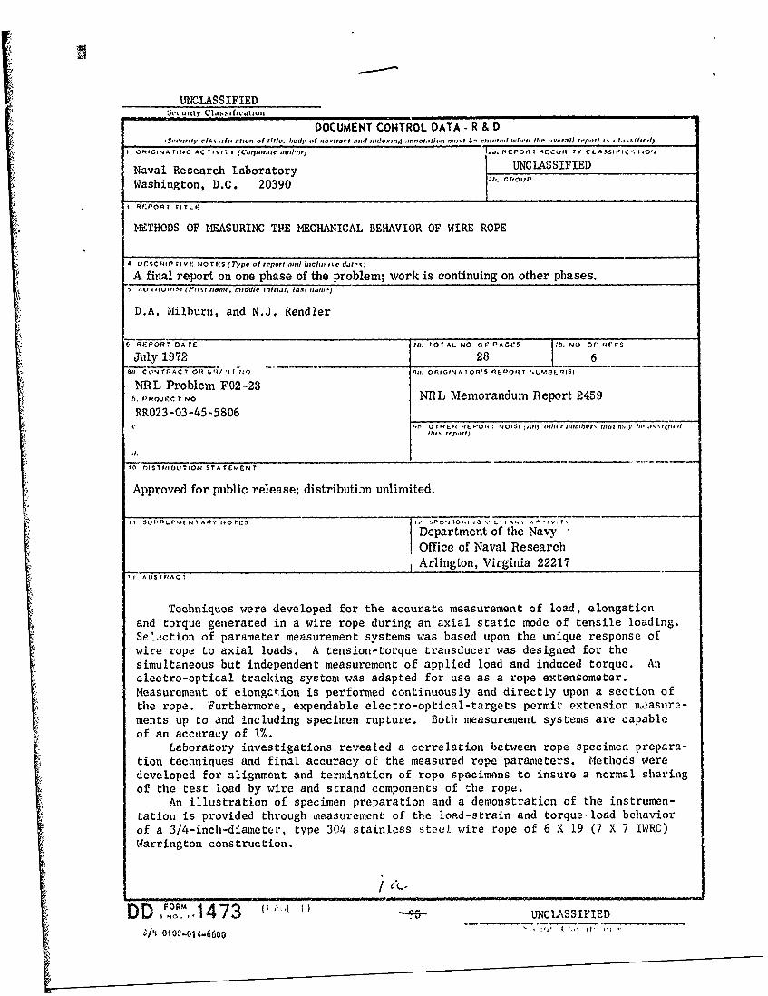
Figure 10 Is a phot-ograph of the actual measurement sstemarranged for a wire rope test. The two optical heads in the pholo-
5

graph are shown mounted on adjustable platfo-ms chat are attached tothe seismic stand on the right side of the rope. This stand is capableof being positioned away from the targets to insure a large enoughoptical field of view. For testing purposes, a field of view equal to125% of estimated target displacement determines the optical head totarget working distance. Accuracy of the tracking system is 0.1% ofthe field of view.
The procedure ior extensometer calibration ie illustrated inFig. 11. A specially designed mcchanical micrometer slide is shownclamped to the pre-loaded rope. The device had its own targets whichare situated parallel to and flush against the rope targets. Byrotation of the micrometer slide screw its targets are displaced inkncwn increments.
Targetir' techniques are important. They are the only items inthe complete measuring system that can be considered expendable becausewire rope break strength tests frequently destroy them. The targetsshown in Fig. 12 were designed specifically for the 3/4-inch-diameterwire rope. Prior to a rope test, the targets are clipped to the ropeand .Insitioned so that each weld point is at least one rope lay lengthaway from the nearest terminator. Next, the targets are rigidlyattached to a single wire of the rope by means of a spot-weld. Thespot-weld is sufficiently small so as not to effect the gross behaviorof the rope.
MECHANICAL BEHAVIOR fi A WIRE ROPE
With the specimen preparation techniques perfected and the instru-mentation mai!" ol-rational it was possible to accurately measure theload-strain ard torque-load behavior of the 3/4-inch-diameter wire ropeshown in Fig. 1.
A three million pound capacity testing machine was selected forthis work. The test machine is shown in Fig. 10. It has a single-screw drive and applies load to the rope at a constant rate of machinehead displacement. Maximum crosshead clearance is 11 feet, threeinches, which permitted a rope free length of seven feet, four inchesafter allowance for test fixtures, load-torque transducer and opera-tional clearance. The test machine was to be used to only 1.7% of itsioad capacity since during the test axial load would not exceed50,000 lb. The machine load frame is extremely massive. This featureaffurded an advantage in that the torsional lo.•s in transducer output,due to rotational displacement of the upper crosshead, would benegligible. Excessive capacity, however, provided a disadvantagebecavse the machine weigh system had insufficient load sensitivity forrope tension measurements. T s was remedied with the addition ofaxial luad capability to the transducer described earlier.
6

When conducting wire rope tests, a small pre-load is oftennecessary to eliminate initial measurement error. In this instance,a 150 lb load was utilized to straighten the initially loose 3/4-inch-diameter rope and provide it with sufficient rigidity to permitcalibration of the electro-optical system. The test machine wasoperated at a head displacement rate of 0.0745 in./min. Test procedurewas simply to give the rope a single load cycle and then load it torupture. The specimen was loaded from 150 lb to 31,000 lb, 33,000 lbto 4000 lb, and 4000 lb to rupture. Load was contimously appliedduring the test.
Load-elongation and torque-load data were simultaneously recordedon X-Y recorders. The load-strain behavior is given in Fig. 13. Arope break strength of 47,350 Ib, with 4.0% elongation at rupture, wasachieved in this test. The effect of construcuional stretch is clearlyevidenced by the contrast in load-strain behavior of the initial andfirst cycle load curves. From Fig, 13, the constructional and firstcycle elastic moduli were calculated to be 8.88 x 10⁶ psi and 14.48 x10⁶ psi respectively. Note that the initial load-strain curve isnever reached again in the subsequent loading. Under the cycled load,the rope yields a hysteresis loop between the loading and unloadingcurves A and B. This behavior directs attention to the internalfrictional forces present in the rope.
In order to measure the torsional response of the rope it wasnecessary to impede rotation of the rope ends. Torque-load behaviorof the rope is illustrated in Fig. 14. For all practical purposes, theinitial torque-load curve (0 to 33,000 1b) is linear. Slope of theinitial curve is 0.0574 in.-lb per lb of rope load. Upon load cyclingthe rope, a small difference in torque-load behavior was evident.Torsional response during the second loading was also linear at0.0552 in.-lb per lb of load, a decrease of 3.8% over the initialloading.
Figures 13 and 14 represent tile mechanical response of this ropeto a given single load cycle. Parameters that include load, inducedtorque and elongation were measured to an accuracy of 1%. Three factsare available for corroboration of this statement. First, all measure-ment systems were calibrated to an accuracy of at least 1%. Second,post test examination of terminator cores indicated that they both metthe standards outlined earlier. Finally at rupture, Fig. 15, wiresand strands broke near the center of the test lenigth.
CONCLUDING REMARKS
Efforts during the current study had largely been directedtowards a perfection of technique and development of instrumentationnecessary for an accurate measurement of rope parameters. Even thoughinstrumentation capability was demonstrated for static loading, it
7

does have the capability to measure rope parameters under dynamicloading. Furthermorb, the instrumentation can be extended to accomo-date fiber ropes and electromechanical cables.
The peculiarities of wire rope constructional form requiresspecial precautions with regard to specimen preparation. Because ofthis, procedures have been developed for mounting rope specimens witha minimum amount of relative displacement of wires and strands duringcutting and terminating. A special alignment fixture was also designedto insure near-perfect axial alignment between the terminators andrope. Speltering techniques were modified to obtain a more completeflow of zinc-spelter. All of the above served to guarantee that thetest machine would transfer load to the rope without the introductionof abnormal wire stresses.
Currently these methods are being utilized for the test andevaluation of a newly developed titanium rope and also to analyze theeffect of marine service damage upon the mechanical behavior of moor-ing lines. A precise knowledge of their performance characteristicsis required and can be obtained through use of these techniques. Itis intended that this report will serve as e eference to these andfuture NRL rope studies.
ACKNOWLEDGEMENT
The authors wish to acknowledge the assistance of Mr. John Bachmanduring the experimental development of termination and targetingtechniques.
8

°'1
REFERENCES
1. Rendler, N. J., "Damage Analysis of Wire Rope from a 34-MonthOcean Mooring," NRL Memorandum Report 2196, October 1970.
2. Hruska, F. H., "Calculation of Stresses in Wire Rope," Wire andWire Products, Vol. 26, September 1951, pp. 766-767, 799-801.
3. 1iruska, F. H., "Radial Forces in Wire Ropes," Wire and WireProducts, Vol. 27, May 1952, pp. 459-463.
4. 11ruska, F. H., "Tangential Forces in Wire Rope," Wire and WireProducts, Vol. 28, May 1953, pp. 455-460.
5. United States Steel, "Wire Rope Engineering Handbook," Reprinted
October 1968, pp. 100-101.
6. Fisher, F. E., "Instrumentation for Mechanical Analysis,"University of Michigan, 1966.
9

Fig. I -A 3 /4-inch -diameter, type 304 stainlesssteel wire rope of 6 x 19 (7 x 7 IWRC) Warringtonconstruction,
10

ZINC POUR OPEN- ENDSPELTER
SOCKET BASKET
ZINC-ROPE CORE
TRANSITION ZONE
WIRE ROPE----o-
Fig. 2 - Penetration of zinc throughout the wiretransition zone is desirable
I 11

C)
0)
- 0 0
4 .
.- 0
10
*0 0
bfl

Fig. 4 -Zinc has penetrate(] tile full length
of the socket basket to grip the rope in near-
perfect configuration.

XI
Fig. 5 -Early congealing of the zinc pre-vented a complete metal flow throughoutthe length of socket basket.
14

AI %rs,.. n - -r
C)
14 cn c
Cd
1.50

M0 - 0
I': If)
zr0 0
< 0)
0 I0w 0f)
0~
W (
z l 0f
Z 0
><0 Ca
01
-0 C a
0 1L
a) C
C/) 0 C
(9 0U
z -0 0
U) D> 0W
w -0
o 0
00 0 0 0 00. 0 0 0 0n
tr)16

, T
j"
Fig. 8 - Tension-torque transducer is shown assembledin the calibrator on the right
17

z
0I-Z
ZW W ZW
LLO -o 0
0 1--0,-W
W < 4 w
ccrwFN wwT .LL0
W:) w5
O z0 w0
4-)
~~U) P~U
0 4-4
-Jo[ ~0 -J,
I8
Fig. I( I~nK 1p (t t in 1) thie mill ion pound capacity
19I a ilt

IL'',
- Im
illi tree mlill ioj1 jpottl I (bMW I nil it;
oi'

lice
'~e COj
Fig. 12 - Electro-optical target design
21

0
Cl) 0
< -J <
<: 0w 40 W
(7) 1: Cl)WL (Q . U)(r- w U')w o 0
CC. 0Cr (-) 0
0) U. 0t
l'F LL X :iW W0 0z j I--.
w wiWw a(9 ~ xa: LdwwC
3: 0
,l) I < fn)
D OD
d -00 0 wW0
WrW0.0
C)d
coi
K) U)
0 c
(Di*10
0 00 0 0 0 0 C)0o 0 0o 0 0(~ 0N~ to) d \7U) to 0o 0 o
(qi) oVO-1
22

000,a
010AL00
j• -0 :0
0 CC02
,,O 0 *-- -
S° _oM ro
0
UJ .0 .-
. 0_o P0 0
I , I , I II °~0 >
CCJ
0
a 1 0o 1000
< 0
• I • •-- J --
z00
Cro
a I I I I2--') 3 OO
W ,'}
(i
It