metrics for evaluating distributed manufacturing control systems
TRANSCRIPT

Metrics for evaluating distributed manufacturingcontrol systems
Robert W. Brennan*, Douglas H. NorrieDepartment of Mechanical and Manufacturing Engineering, University of Calgary,
2500 University Dr. N.W., Calgary, Alberta, Canada T2N 1N4
Abstract
In this paper, two classes of metrics are proposed that can be used to evaluate alternative manufacturing control architectures:
those dealing with the controlled system (i.e. the manufacturing system) and those dealing with the control system. In order to
illustrate the use of these metrics, the problem of scheduling a simple manufacturing cell is tackled using two test control
architectures and the performance of these alternative approaches is evaluated using a modular discrete-event simulation model.
The results of the paper suggest that it is worthwhile to use both manufacturing and control system performance measure to
evaluate alternative control architectures, especially when considering dynamic architectures such as a Holonic Manufacturing
System (HMS; i.e. architectures that adapt to changes in the manufacturing environment).
# 2003 Elsevier Science B.V. All rights reserved.
Keywords: Distributed control systems; Performance metrics
1. Introduction
To meet the requirements of agile manufacturing,
research in the area of manufacturing systems control
has moved away from traditional centralised appro-
aches and has focused on the development of a spectrum
of distributed control architectures that range from
hierarchical structures to non-hierarchical (NH) or
heterarchical structures [1].
The motivation for this work is based on the
requirement for manufacturing systems that are cap-
able of adapting to internal (e.g. machine breakdown)
as well as external (e.g. changes in demands or product
specifications) disturbances. In these systems, the
removal and introduction of new manufacturing equip-
ment and the introduction of new products should be
easily achievable, whereby the manufacturing system
and their control should be easily re-configurable.
Since the environment the manufacturing systems will
be operating in is continually changing they must as
well posses the ability to change dynamically. This
concerns the control architecture, the physical system
and the tuning of certain control parameters, thus
making the systems self-adapting and self-tuning.
Even though some of the suggested architectures
seem promising, none has been fully capable of
coping with the demands that influence the manufac-
turing system and its performance. In order for the
manufacturing systems to fully cope with these
demands current research is heading towards manu-
facturing control architectures that are hybrids of the
Computers in Industry 51 (2003) 225–235
* Corresponding author. Tel.: þ1-403-220-5798;
fax: þ1-403-282-8406.
E-mail addresses: [email protected] (R.W. Brennan),
[email protected] (D.H. Norrie).
0166-3615/03/$ – see front matter # 2003 Elsevier Science B.V. All rights reserved.
doi:10.1016/S0166-3615(03)00038-1

hierarchical and heterarchical architectures. The
purpose is to combine the predictability of the cen-
tralised and hierarchical control architectures with the
agility and robustness against disturbances and high
degree of adaptability of the heterarchical control
architectures.
Holonic Manufacturing Systems (HMS) has been
suggested as a concept for these future manufacturing
systems [2]. The concepts of HMS originate from the
Hungarian philosopher Arthur Koestler, who (based
on his study on living organisms and social organisa-
tions) stated that wholes and parts in the absolute sense
do not exists anywhere [3]. Instead, everything is
made up of dynamical hierarchies. Koestler coined
the term holon as the basic element of these systems.
The holon posses the basic characteristics of auton-
omy and co-operation, whereby it is capable of plan-
ning and executing for itself. Furthermore, the co-
operation capability enables it to co-operate with
other holons in order to achieve a common goal or
objective. Holons are aggregated in to holarchies. A
holarchy is a holon within itself. The holarchies
describe the dynamic hierarchies of a Holonic System
and throughout the life cycle of a Holonic System
these dynamical hierarchies will be created and
deleted on a regular basis as a response to the current
situation.
Multi-Agent Systems (MAS), a technology which
has emerged through research within Distributed Arti-
ficial Intelligence (DAI), is a promising enabler for
HMS [4,5]. Since the holon encompasses in most
cases both a software part and a physical part, software
agents play an important role in implementing Holo-
nic Systems.
An important question that follows from research in
this area is, given that Holonic Systems are dynamic in
nature, what is the most appropriate architecture at any
given time? This decision (i.e. should the Holonic/
Multi-Agent System should be run as a hierarchy,
heterarchy or a hybrid?) corresponds to defining the
degree of autonomy of the holons/agent within the
manufacturing system. This paper raises these ques-
tions and suggests a number of metrics that can be
used to evaluate manufacturing control architectures.
In order to provide an objective comparison of
alternative control architectures, two test control archi-
tectures are identified: a non-hierarchical or ‘‘heter-
archical’’ control architecture, and a unconstrained
hierarchical (UH) architecture. These two architec-
tures, as well as a simple emulated test environment
are described in Section 2.
In Section 3, two classes of metric will be defined,
the first dealing with the performance of the manu-
facturing system being controlled and the second
dealing with the performance of the control architec-
tures themselves. Next, we evaluate the relative per-
formance of these architectures using these measures
in Section 4. Finally, we provide our conclusions
based on our experimental work with the two test
control architectures in Section 5.
2. The test environment
2.1. The test control architectures
Fig. 1 provides a top-level view of the two control
architectures investigated in this paper. The key rela-
tionship that is being investigated in the experiments
that follow is how increases in planning horizon affect
the performance of an initially reactive control archi-
tecture. With this in mind, the unconstrained hierarch-
ical architecture can be viewed as a hybrid of the
characteristically reactive non-hierarchical architec-
ture: i.e. the UH architecture combines the planning
capabilities of hierarchical architectures with the reac-
tiveness of heterarchical architectures.
The NH architecture consists of two physical
agents: Part Agents and Machine Agents that are
associated with individual parts and workstations,
respectively, in the emulated manufacturing system.
Part Agents encapsulate the information necessary to
manage the processing of individual parts such as the
part’s process plan, machining requirements, proces-
sing status, and due date; Machine Agents are con-
cerned with managing the individual workstations in
the manufacturing system and contain information
concerning the workstations’ machining capabilities
and status.
The two types of agents in the NH architecture co-
ordinate their actions using the contract net approach
[6]: in this case, the Part Agents serve as managers
and the Machine Agents serve as contractors. A part-
oriented bidding-based approach is used to allocate
part processing to machines where Part Agents
broadcast requests to have available part operations
226 R.W. Brennan, D.H. Norrie / Computers in Industry 51 (2003) 225–235

processed on workstations, while Machine Agents
respond with an estimate of how many operations
they can process and the time it will take to complete
this processing. Part Agents then collect proposals
and choose the best one based on how likely the
proposal is to help them satisfy their due date com-
mitments. Each Part Agent repeats this process until
all of its operations are completed. More details of
the Part Agent and Machine Agent interactions can
be found in [7].
Various researchers have used this same approach to
resource allocation. Most notably, Duffie and Piper [8]
showed on a similar test-bed to the one used here that
this approach leads to natural load balancing, a reli-
able mechanism for failure recovery, and allows
agents to be introduced and removed dynamically.
As noted previously, when Part Agents broadcast
their call-for-proposals they request bids for all avail-
able operations. Since there are typically precedence
relationships between operations, not all operations
can be assigned to machines in one bidding cycle. For
the parts that are processed in our emulated system,
the experimental results have shown that Part Agents
award an average of 1.88 operations (out of a total of
eight operations) per bidding cycle, or in other words,
the NH architecture plans approximately two opera-
tions ahead. The UH architecture has been designed to
allow this horizon to be varied.
Like the NH architecture, the UH architecture Part
Agents broadcast a call-for-proposals for processing,
but unlike the NH architecture they specify the max-
imum number of operations (N) that they would like to
see completed per bidding cycle (i.e. the planning
horizon). This message is broadcasted to a middle agent
called a Bargainer Agent that serves as a facilitator to a
partial hierarchy of related agents as is illustrated in
Fig. 1 (in this case, each Bargainer Agent is assigned to
a manufacturing cell consisting of a milling station
Machine Agent and a turning station Machine Agent).
Like the NH architecture, the UH architecture uses
the contract net for resource assignment. Part Agents
request bids from Bargainer Agents and Bargainer
Agents request bids from Machine Agents. As noted
previously, the UH architecture can be viewed as a
hybrid version of the NH architecture that allows Part
Agents to plan ahead. The Bargainer Agents are
responsible for managing these plans in the form of
a schedule. A more detailed description of the Part
Agent, Bargainer Agent and Machine Agent interac-
tions can be found in [7].
Fig. 1. The test control architectures.
R.W. Brennan, D.H. Norrie / Computers in Industry 51 (2003) 225–235 227
2.2. The experimental test-bed
For the experiments conducted for this research the
two test control architectures are evaluated using a
modular experimental test-bed developed for this
research [9]. This test-bed allows various control
architectures to be developed in an object-oriented
environment (Cþþ) and linked to a discrete-event
simulation model (Arena) of the test manufacturing
system.
Since the majority of the control architecture work
described in the literature is concerned with part
scheduling in flexible manufacturing systems (FMS)
[10,11] and cellular manufacturing systems [12,13],
the system that is investigated for this research is
concerned with the scheduling of parts through a
simple manufacturing cell. For the experiments
reported in this paper, a simulation model of a simple
manufacturing cell was used that is similar in structure
to the manufacturing cells investigated by others in
this area [8,14]. This model consists of four automatic
machines connected by a material-handling robot.
Each of the machines in the system is capable of
performing various operations depending upon its tool
set-up, which is limited by the number of tools that can
be held at the machine’s local tool storage area. As
well, each machine in the investigated system is prone
to failure. Details of this test environment can be found
in [9].
3. Metrics used to evaluate the test controlarchitectures
The main purpose of this section is to introduce the
metrics that are used to evaluate the test control
architectures described in the previous section. Two
classes of metric will be defined, the first dealing with
the performance of the manufacturing system being
controlled and the second dealing with the perfor-
mance of the control architectures themselves. A
second purpose is to further characterise these control
architectures using a number of structural parameters
that are defined later in this section.
Although the primary focus of the research pre-
sented in this paper is concerned with gaining insights
into alternative manufacturing control architectures, it
is important to note at this point that the main purpose
of any research of this nature is improved manufactur-
ing system performance. With this in mind, this sec-
tion will start by introducing the manufacturing
system performance measures in Section 3.1. Next,
in Section 3.2, metrics will be described that relate
directly to the test control architectures. First, we
discuss the notion of control system performances
measures. To illustrate this concept, a specific mea-
sure, inter-agent coupling, is described that is later
evaluated for both test control architectures in Section
4. Next, the notion of control system structural para-
meters that are intended to describe the characteristics
or features of different types of control architectures,
is described. Again, a single metric is developed to
illustrate this concept: decision-making flexibility.
3.1. Manufacturing system performance measures
Ultimately, control system design is concerned with
the efficient operation of the manufacturing system. In
order to evaluate the performance of the manufactur-
ing system for various control architectures it is
important to define a number of manufacturing system
performance measures that will be evaluated by
experimentation.
Examples of the types of performance criteria [15]
that can be investigated follow:
(i) criteria based on job completion times (e.g.
average job flowtime),
(ii) criteria based on due date performance (e.g.
average lateness, average tardiness, proportion
of tardy jobs),
(iii) criteria based on inventory costs or resource
utilisations (e.g. number of parts waiting,
number of finished goods, number of parts in
process, machine idle time).
The three sets of criteria described above relate to
the primary objectives that apply to scheduling pro-
blems [16]. First, we are concerned with minimising
the amount of time that jobs spend in the manufactur-
ing system (criteria based on completion time and
criteria based on inventory levels). Next, a typical goal
is to reduce late job completion (criteria based on due
dates). Finally, an important consideration for manu-
facturing systems, consisting of expensive equipment
and personnel, is to fully utilise their limited capacity
(criteria based on utilisation).
228 R.W. Brennan, D.H. Norrie / Computers in Industry 51 (2003) 225–235
Unfortunately, these three scheduling objectives are
in conflict with each other in typical manufacturing
systems. For example, as Vollmann et al. [16] point
out, due date performance can be improved if more
resource capacity is provided but this will cause
resources to be less intensively utilised. Similarly,
flow time performance can be improved (i.e. jobs
can be processed in less time due to reduced conges-
tion) under the same conditions.
The relative performance of the test control archi-
tectures have been evaluated using the three basic
scheduling objectives described above. In the experi-
ments that are reported in [9], the following manu-
facturing system performance criteria were evaluated:
average flow time, average tardiness, and average
work-in-process. In Section 4, we evaluate the NH
and UH control architectures’ average flow time per-
formance relative to the control system metrics
described in the next section.
3.2. Control system metrics
As noted previously, we have found it convenient to
evaluate alternative control architectures in terms of
two classes of control system metrics: control system
performance measures and control system structural
parameters. In this subsection, we look at each of these
metrics.
3.2.1. Control system performance measures
The control system performance measure described
in this paper is one of several measures investigated in
[17] that are primarily based on message traffic in the
control architecture (coupling, listening coefficient)
and how likely individual agents are to change during
operation (volatility). In this paper, the focus will be
on inter-agent coupling.
Coupling is a term that is often used in the literature
to describe the strength or weakness of the relation-
ships between agents in a control system. In order to
achieve overall control system objectives, agents must
somehow co-ordinate their behaviour through their
interactions with each other. These interactions may
lead to a system that can be described as either
‘‘tightly’’ or ‘‘loosely’’ coupled, or somewhere in
between. For example, Davis and Smith [18] define
a distributed problem solving system as a system that
achieves the ‘‘co-operative solution of problems by a
decentralised, loosely coupled collection of problem
solvers’’. In this case, the definition of a loosely
coupled system is one where agents spend most of
their time in computation rather than in communica-
tion [18]. Although it is stated in the literature that the
degree of coupling between agents plays an important
role in distributed systems, definitions such as Davis
and Smith do not lead to a relative measure of coupling
between alternative control architectures.
In the experiments presented in Section 4, the
coupling, cij, from agent i to agent j is defined as:
cij ¼number of messages sent from i to j
number of messages sent from i to all others(1)
In other words, coupling between agent i and agent j is
a measure of the proportion of agent i’s transmitted
messages that are sent to agent j. Clearly, with this
definition, cij can be different from cji so the coupling
between them needs to be considered from the per-
spective of each of the agents. From this definition, cij
can be thought of as the transmit coupling between
agent i and agent j. Similarly, an equation can be used
to determine the receive coupling, cij0, between agent i
and agent j (i.e. the proportion of the messages
received from agent j to those received by all other
agents).
An example of the use of the inter-agent coupling
metric is to provide insights into the relationships
between the various agents involved in the tasks
carried out by the architecture. Since holonic archi-
tectures are intended to by dynamic and metamorphic
in nature, it is conceivable that an outside observer
may not be able to clearly describe the relationships
between holons at any given time. Inter-agent cou-
pling could be used by a meta-controller to evaluate
the performance of the control system and advise
when and where changes should be made [19]. Deci-
sions of this type will require the meta-controller to be
capable of characterising the relationships between
agents (e.g. whether a given group of holons are
characteristically ‘‘hierarchical’’ or ‘‘heterarchical’’).
3.2.2. Control system structural parameters
Unlike performance measures, control system struc-
tural parameters are intended to help define each
individual architecture with greater precision and to
provide a basis for comparison between each of the
approaches. It is through the analysis of these para-
R.W. Brennan, D.H. Norrie / Computers in Industry 51 (2003) 225–235 229
meters that the inherent characteristics of various
decision-making architectures can be evaluated. One
structural parameter that is commonly used in the
literature is planning horizon [20,21]: i.e. the full time
span that an agent considers. Parunak [22] also pro-
posed using decision-maker specialisation to charac-
terise the different capabilities of agents in a control
architecture. In this paper, we define a parameter that
allows control architectures to be compared on the
basis of how much decision-making flexibility each
architecture offers that is based on the computer
science theory of formal languages [23].
The flexibility referred to here is related to the
number of possible ways that agents in the control
system can generate a solution to the control problem.
In a very flexible system, a variety of agents will co-
operate to generate a solution (e.g. complete a part
process plan) that reflects the current state of the system.
Decision-making flexibility is necessary to handle dis-
ruptions such as machine failures and fluctuations in
demand; this will require agents with the capability of
altering their behaviour subject to these disruptions.
In order to quantify the decision-making flexibility
of alternative control architectures, a method is
required that can be used to describe the different
types of decisions that are available to agents. The
method that has been chosen involves describing the
structure of the messages (i.e. the rules for construct-
ing messages) that are passed between agents in a
control architecture using formal language techniques.
Since the motivation for formal language techniques is
to provide a precise characterisation of the structure of
languages, these techniques seem appropriate for the
type of analysis that is required for the control archi-
tecture message structures. The approach used in this
paper involves two main steps:
(i) defining the types of messages that are passed
between agents, and
(ii) defining the structure that message strings can
take given the decision-making options available
to agents in the control architecture.
The formal language technique provides informa-
tion concerning the number of possible alternatives
that agents in a given test control architecture have
when making a decision. When there is more than one
option for an agent, a method is required that gives a
relative indication of this decision-making flexibility.
In order to quantify decision-making flexibility a
flexibility function is developed that is an extension
of the routing flexibility function defined by Upton [24].
This, in combination with a formal language descrip-
tion of inter-agent coupling is used to obtain a measure
of the relative decision-making flexibility for each of
the test control architectures. For example, when an NH
architecture Part Agent requests bids from the Machine
Agents the following set of messages is generated by the
control system: [rqb][1m_sb][2m_sb][3m_sb][4m_sb].
In other words, a bid request from the Part Agent [rqb],
results in each of the four machines responding with
specific bids [m_sb].
At this point, the Part Agent can respond with one of
four different messages, depending upon which
machine it selects for processing. For example, if
the Part Agent decides to award the part’s processing
to machine #1, the following string will occur:
[award_1m][1m_er]. In other words, the Part Agent
awards the processing to machine #1, [award_1m],
then the Machine Agent evaluates the Part Agent’s
request for processing [1m_er]. The full phrase gram-
mar for the NH control architecture is shown in Fig. 2.
Using this phrase grammar, we can explicitly define
decision-making options that are available to the NH
control architecture. This same process is performed
for the UH control architecture. The phrase grammar
for this architecture is shown in Fig. 3.
This formal language analysis can be further devel-
oped to show how Upton’s [24] measure of routing
flexibility in an FMS can be extended to an entropic
measure of ‘‘decision-making flexibility’’ for a given
control architecture. Upton [24] defines ‘‘routing flex-
ibility’’, pi, in an FMS where, pij, is the cost advantage
of routing a part from machine j to machine i.
xi ¼ �Xn
j¼1
pij logðpijÞ (2)
This ‘‘cost advantage’’ is directly related to processing
time in this definition. It is proposed that the same
measure of flexibility be used here with ‘‘cost advan-
tage’’ in this definition relating to the ‘‘advantage’’ or
probability of a given decision being made. This will
require the grammars for the control structures to be
written as stochastic grammars. The productions will
be of the following form:
v)p
w
230 R.W. Brennan, D.H. Norrie / Computers in Industry 51 (2003) 225–235

where p represents the probability of the production
(v;w) occurring.
The representation of the control system in terms of
a stochastic grammar follows logically from the per-
vious definitions. For example, for the NH control
architecture, the productions resulting from the non-
terminal symbol ‘‘R’’ (i.e. response to bids) each have
an equal probability of occurring:
R)0:25
½award 1m½1m erE
R)0:25
½award 2m½2m erE
R)0:25½award 3m½3m erE
R)0:25
½award 4m½4m erE
i.e. the part may select any of the four machines for its
processing.
In order to extend the definition of decision-making
flexibility to the control language, the entropy for the
stochastic productions resulting from a non-terminal
symbol w 2 VN can be determined [24]. First, the
decision-making flexibility resulting from each of
the productions can be calculated using a modified
form of Eq. (2):
x ¼ �Xn
i¼1
pi log2ðpiÞ (3)
where i ¼ 1; 2; . . . ; n represents the number of alter-
native decisions that the production allows. For
example, we can calculate the decision-making flex-
ibility for the NH architecture example discussed
above:
x ¼ �Xn
i¼1
pi log2ðpiÞ ¼ �4 log2ð0:25Þ ¼ 2
To determine the overall decision-making flexibility
for a control architecture, all of the productions for the
control architecture must be considered. The technique
Fig. 2. Phrase grammar for the NH control architecture.
R.W. Brennan, D.H. Norrie / Computers in Industry 51 (2003) 225–235 231
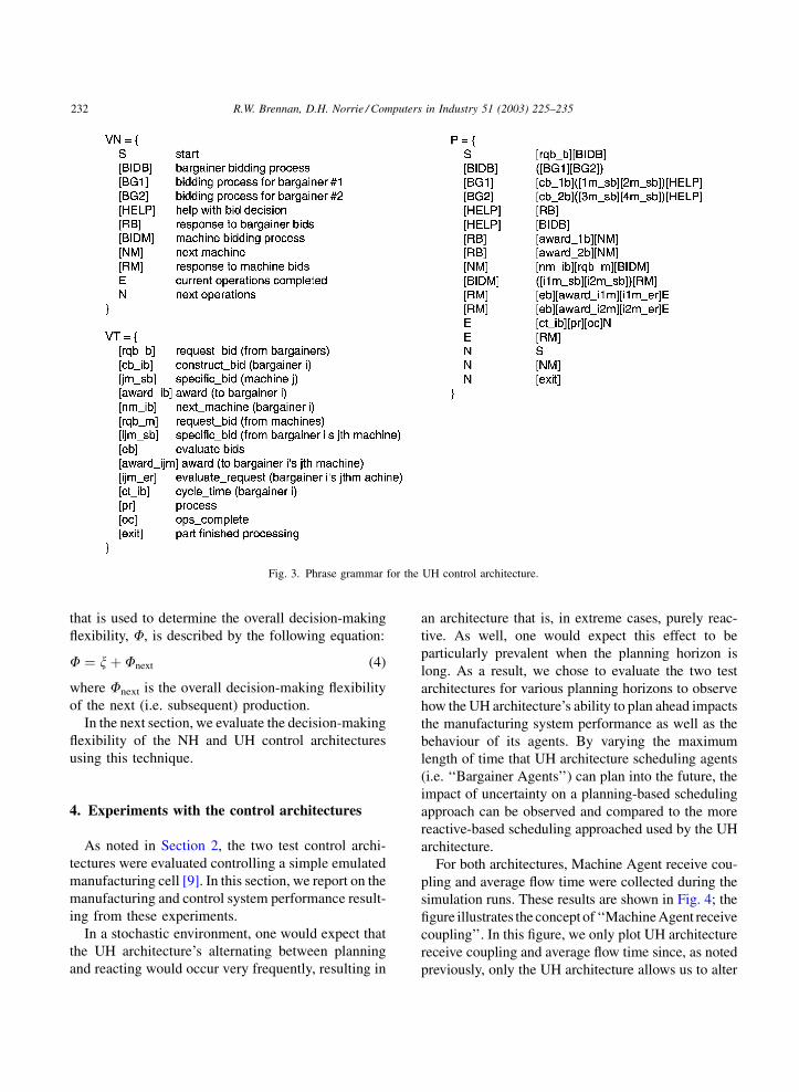
that is used to determine the overall decision-making
flexibility, F, is described by the following equation:
F ¼ xþ Fnext (4)
where Fnext is the overall decision-making flexibility
of the next (i.e. subsequent) production.
In the next section, we evaluate the decision-making
flexibility of the NH and UH control architectures
using this technique.
4. Experiments with the control architectures
As noted in Section 2, the two test control archi-
tectures were evaluated controlling a simple emulated
manufacturing cell [9]. In this section, we report on the
manufacturing and control system performance result-
ing from these experiments.
In a stochastic environment, one would expect that
the UH architecture’s alternating between planning
and reacting would occur very frequently, resulting in
an architecture that is, in extreme cases, purely reac-
tive. As well, one would expect this effect to be
particularly prevalent when the planning horizon is
long. As a result, we chose to evaluate the two test
architectures for various planning horizons to observe
how the UH architecture’s ability to plan ahead impacts
the manufacturing system performance as well as the
behaviour of its agents. By varying the maximum
length of time that UH architecture scheduling agents
(i.e. ‘‘Bargainer Agents’’) can plan into the future, the
impact of uncertainty on a planning-based scheduling
approach can be observed and compared to the more
reactive-based scheduling approached used by the UH
architecture.
For both architectures, Machine Agent receive cou-
pling and average flow time were collected during the
simulation runs. These results are shown in Fig. 4; the
figure illustrates the concept of ‘‘Machine Agent receive
coupling’’. In this figure, we only plot UH architecture
receive coupling and average flow time since, as noted
previously, only the UH architecture allows us to alter
Fig. 3. Phrase grammar for the UH control architecture.
232 R.W. Brennan, D.H. Norrie / Computers in Industry 51 (2003) 225–235

its planning horizon. The NH architecture receive cou-
pling and average flow time results are indicated by
arrows on the left and right of Fig. 4, respectively.
Rather thanplottingMachineAgentcouplingdirectly
in this figure, a ratio of supremal agent (i.e. Part or
Bargainer Agent) over peer agent (i.e. Machine Agent)
coupling is used. By presenting inter-agent coupling in
this way, the relative coupling between the agents con-
cerned with the task of part scheduling in each archi-
tecture can be evaluated: i.e. ‘‘loosely’’ coupled agents
would have a supremal/peer ratio close to 1 while
‘‘tightly’’ coupled agents would have a supremal/peer
coupling that diverges from 1 (greater than 1 would
indicate a supremal/infimal or a ‘‘master/slave’’ rela-
tionship characteristic of hierarchical architectures).
Given that the UH architecture has the ability to
plan or react, one would expect that, as a result of
disturbances such as machine failures and processing
delays, the UH architecture would start to behave like
the NH architecture. As one can see in Fig. 4, the
simulation results show a trend in this direction: i.e. an
increase in UH architecture Machine Agent coupling
agrees with the prediction that the combination of
uncertainty and long planning horizons would result in
frequent re-planning.
These results indicate that as the UH architecture
planning horizon increases, its Bargainer and Machine
Agents start to behave more reactively as a result of re-
scheduling (i.e. as planning horizon is increased,
Bargainer and Machine Agents coupling is higher
or ‘‘tighter’’ than the Machine Agent peer-to-peer
coupling). This relatively tighter coupling between
these agents results in a clear supremal/infimal rela-
tionship characteristic of hierarchical architectures.
Fig. 4. Machine Agent receive coupling.
R.W. Brennan, D.H. Norrie / Computers in Industry 51 (2003) 225–235 233
As well, the receive coupling results also indicate
that there is a degree of hierarchy that exists in non-
hierarchical or heterarchical control architectures: i.e.
Machine Agent receive coupling for the NH architec-
ture is greater than 1, indicating a supremal/infimal or
‘‘master/slave’’ relationship characteristic of hierarch-
ical architectures.
When we evaluate the overall decision-making
flexibility of the two architectures we see that the
UH control architecture displays a higher decision-
making flexibility than the NH control architecture:
FNH ¼ 2:5
FUH ¼ 3:5
This is a result of the UH architecture’s Bargainer
Agents’ ability to choose to either use their own
machines for part processing or request help from
another Bargainer Agent. If this option is not available
to the UH control architecture’s Bargainer Agents, the
UH control architecture’s decision-making flexibility
reduces to that of the NH architecture (i.e. FUH ¼2:5). The relative decision-making flexibility results
between the UH and NH control architectures seem to
indicate that the UH control architecture’s use of a
schedule does not inhibit the flexibility of its agents. In
fact, the average flow time results shown in Fig. 4
indicate that this increased flexibility results in better
overall manufacturing system performance (i.e. aver-
age flow time performance).
5. Conclusions
In this paper, we have looked at two basic classes of
performance metrics (manufacturing system and con-
trol system) that can be used to evaluate the relative
performance of alternative control architectures for
manufacturing and have provided examples of each.
These metrics were then used to compare two basic
control architectures, a non-hierarchical or ‘‘heter-
archical’’ control architecture (NH) and a hybrid
control architecture (UH) on the same experimental
test-bed.
As a result of this work, we feel that benefits can be
gained from going beyond traditional manufacturing
system performance measures such as average flow
time, to the definition and use of control system
performance measures and structural parameters.
For example, quantitative results using measures such
as inter-agent coupling can be used to gauge the
interactions between agents in a dynamic control
architecture such as a Holonic Manufacturing System.
When these metrics are combined with other metrics,
they can potentially be used by system designers (or
high-level meta-agents) to learn the characteristic
interactions between agents for given performance
requirements. In other words, the control system
can use performance feedback (i.e. control and man-
ufacturing system performance measures) based on its
current and past configurations (i.e. its current and past
structural parameter values) to tune itself to meet the
system’s performance objectives. These performance
objectives are typically stated in terms of manufactur-
ing system performance measures.
For example, the experiments reported in this paper
have shown that, although the UH architecture agents
start to behave in a similar fashion to the NH architec-
ture agents as planning horizon is increased (i.e. the two
architectures’ inter-agent coupling start to converge),
the added flexibility of the agents in the UH architecture
give it an added advantage over purely reactive
approaches: i.e. because of the highly structured nature
of shop floor control, some degree of planning is useful,
even in an unpredictable environment.
Acknowledgements
The authors wish to thank Natural Sciences and
Engineering Research Council for their generous sup-
port of this research under grant OGP-019-7339.
References
[1] D. Dilts, N. Boyd, H. Worms, The evolution of control
architectures for automated manufacturing systems, Journal
of Manufacturing Systems 10 (1) (1991) 79–93.
[2] Holonic Manufacturing Systems Consortium, HMS Overview,
http://hms.ifw.uni-hannover.de/public/overview.html, 2001.
[3] A. Koestler, The Ghost in the Machine, Arkana, The Penguin
Group, London, 1967.
[4] S. Bussmann, An agent-oriented architecture for holonic
manufacturing control, in: First Open Workshop on Intelligent
Manufacturing Systems, Europe, 1998, pp. 1–12.
[5] W. Shen, D.H. Norrie, Agent-based systems for intelligent
manufacturing: a state-of-the-art survey, Knowledge and
Information Systems 1 (1999) 129–156.
234 R.W. Brennan, D.H. Norrie / Computers in Industry 51 (2003) 225–235

[6] R. Smith, The contract net protocol: high-level communica-
tion and control in a distributed problem solver, IEEE
Transactions on Computers 29 (2) (1980) 1104–1113.
[7] R.W. Brennan, D.H. Norrie, Evaluating the performance
of reactive control architectures for manufacturing pro-
duction control, Computers in Industry 46 (3) (2001)
235–245.
[8] N. Duffie, R. Piper, Nonhierarchical control of manufactur-
ing systems, Journal of Manufacturing Systems 5 (2) (1986)
137–139.
[9] R.W. Brennan, Performance comparison and analysis of
reactive and planning-based control architectures for manu-
facturing, Robotics and Computer Integrated Manufacturing 6
(2–3) (2000) 191–200.
[10] S. Gershwin, Hierarchical flow control: a framework for
scheduling and planning discrete events in manufacturing
systems, Proceedings of the IEEE 77 (1) (1989) 195–209.
[11] J. Kimemia, S. Gershwin, An algorithm for the computer
control of a flexible manufacturing system, IIE Transactions
15 (4) (1983) 353–362.
[12] A. Jones, A. Saleh, A multi-level/multi-layer architecture for
intelligent shopfloor control, International Journal of Com-
puter Integrated Manufacturing 3 (1) (1990) 60–70.
[13] N. Duffie, V. Prabhu, Real-time distributed scheduling of
heterarchical manufacturing systems, Journal of Manufactur-
ing Systems 13 (2) (1994) 94–107.
[14] P. Valckenaers, H. Van Brussel, L. Bongaerts, J. Wyns,
Holonic manufacturing systems, Integrated Computer-Aided
Engineering 4 (1997) 91–201.
[15] S. French, Sequencing and Scheduling: An Introduction to
the Mathematics of the Job-Shop, Ellis Horwood, Chichester,
UK, 1982.
[16] T.E. Vollmann, W.L. Berry, D.C. Whybark, Manufacturing
Planning and Control Systems, third ed., Irwin, Homewood,
IL, 1992.
[17] R.W. Brennan, Appropriate control architectures for auto-
mated manufacturing systems, Ph.D. Thesis, University of
Calgary, 1996.
[18] R. Davis, R.G. Smith, Negotiation as a metaphor for
distributed problem solving, Artificial Intelligence 20 (1983)
63–109.
[19] R.W. Brennan, C. Sorensen, Evaluating machine agent
coupling of reactive and planning-based control architec-
tures for manufacturing, in: Proceedings of the IEEE
International Conference on Systems, Man and Cybernetics
2000, SMC2000, Tucson, Arizon, USA, pp. 1673–1678.
[20] W. Davis, S.D. Thompson, Production planning and control
hierarchy using a generic controller, IIE Transactions 25
(1993) 26–45.
[21] A. Villa, Hybrid Control Systems in Manufacturing, Gordon
and Breach, London, 1991.
[22] H.V.D. Parunak, Manufacturing experience with the contract
net, in: M. Huhns (Ed.), Distributed Artificial Intelligence,
vol. 1, Pitman, London, 1987, pp. 285–310.
[23] J.E. Hopcroft, J.D. Ullman, Introduction to Automata Theory,
Languages, and Computation, Addison-Wesley, Reading,
MA, 1979.
[24] D.M. Upton, The operation of large computer controlled
manufacturing systems, Ph.D. Thesis, Purdue University, 1988.
Robert W. Brennan is an associate
professor of mechanical and manufac-
turing engineering and director of the
manufacturing program at the Univer-
sity of Calgary, Alberta, Canada. His
research interests include distributed
real-time control of manufacturing sys-
tems, modelling and analysis of manu-
facturing systems, and manufacturing
control architectures. He holds BSc and
PhD degrees from the University of
Calgary. He has over 7 years of industrial experience in project
management and control systems and is a professional engineer and
a member of SME, IIE, IEEE, and INFORMS.
Douglas H. Norrie is adjunct professor
of mechanical and manufacturing en-
gineering at the University of Calgary,
Alberta, Canada. Formerly, he was head
of the Department of Mechanical En-
gineering at the University of Calgary,
and more recently head of the division
of manufacturing engineering. He is also
formerly an adjunct professor of com-
puter science at the same institution. He
has been involved in two major interna-
tional Research Consortia in Intelligent Manufacturing Systems,
being a founder member in the Holonic Manufacturing Systems
and the Gnosis Knowledge systematisation consortia. He is author
or co-author of numerous publications, including seven books. His
research interests are in Intelligent Systems and, in particular, in
Multi-Agent Systems.
R.W. Brennan, D.H. Norrie / Computers in Industry 51 (2003) 225–235 235