metrology measurement capabilities federal manufacturing & technologies...
TRANSCRIPT
Metrology Measurement Capabilities
Federal Manufacturing & Technologies
Leon M. Barnes
KCP-613-6317
Published March 2000
Approved for public release; distribution is unlimited.
Prepared Under Contract Number DE-ACO4-76-DP00613 for the
United States Department of Energy
1 of 60
DISCLAIMER
This report was prepared as an account of work sponsored by an agency of the United StatesGovernment. Neither the United States Government nor any agency thereof, nor any of their employees,makes any warranty, express or implied, or assumes any legal liability or responsibility for the accuracy,completeness, or usefulness of any information, apparatus, product, or process disclosed, or representsthat its use would not infringe privately owned rights. Reference herein to any specific commercialproduct, process, or service by trade names, trademark, manufacturer, or otherwise, does not necessarilyconstitute or imply its endorsement, recommendation, or favoring by the United States Government orany agency thereof. The views and opinions of authors expressed herein do not necessarily state orreflect those of the United States Government or any agency thereof.
All data prepared, analyzed and presented has been developed in a specific context of work and wasprepared for internal evaluation and use pursuant to that work authorized under the referenced contract.Reference herein to any specific commercial product, process or service by trade name, trademark,manufacturer, or otherwise, does not necessarily constitute or imply its endorsement, recommendation,or favoring by the United States Government, any agency thereof or Honeywell International Inc.
Printed in the United States of America.
This report has been reproduced from the best available copy.
Available to DOE and DOE contractors from the Office of Scientific and Technical Information, P. O. Box 62, Oak Ridge, Tennessee 37831; prices available from (865) 576-8401, FTS 626-8401.
Available to the public from the National Technical Information Service, U. S. Department ofCommerce, 5285 Port Royal Rd., Springfield, Virginia 22161, (703) 487-4650.
A prime contractor with the United States
Department of Energy under Contract Number
DE-ACO4-76-DP00613.
Honeywell
Federal Manufacturing & Technologies
P. O. Box 419159
Kansas City, Missouri
64141-6159
2 of 60
KCP-613-6317
Distribution Category UC-706
Approved for public release; distribution is unlimited.
METROLOGY MEASUREMENT CAPABILITIES
Leon M. Barnes
Published March 2000
Table of Contents
INTRODUCTION
MECHANICAL
Length and Coordinate Measurement
Gage Block Measurement
Roundness Measurement
Flatness Measurement
Angle Measurement
Surface Finish Measurement
Vibration
Mechanical Shock
Sound Level
Mass Measurement
3 of 60
Force Measurement
Torque Measurement
Laboratory Glassware Volume
ENVIRONMENTAL, GAS, LIQUID
Temperature
Humidity
Pressure
Gas Flow
Vacuum
Gas Leaks
Viscosity
ELECTRICAL
DC Electrical Measurement
DC Voltage
DC Current
DC Resistance
AC Electrical Measurement
AC Voltage
AC Current
AC Ratio
Capacitance and Inductance
Frequency and Time
RF/Microwave Measurements
Air Lines
Attenuators and Terminations
4 of 60
Network Analyzers and Attenuation Systems
Noise Source
Thermistor Mounts
Probe Station
Power System
OPTICAL AND RADIATION
Optical Radiometric Measurement
Optical Photometric Measurement
Radiation Measurement
Measurement Capability Tables
Dimensional Measurement Capability
Angle, Roughness, and Flatness Measurement Capability
Mass, Force, Torque, Specific Gravity, and Laboratory Glassware Volumetric Measurement Capability
Vibration, Acceleration, Shock, Sound Level Measurement Capability
Environmental Measurement Capability (Temperature, Humidity)
Gas, Liquid Measurement Capability
Electrical Direct Current Measurement Capability
Electrical Alternating Current Measurement Capability
Electrical Radio Frequency/Microwave Measurement Capability
Optical Radiometric Measurement Capability
Optical Photometric Measurement Capability
Measurement Standards Tables
Dimensional Standards
5 of 60
Angle, Roughness, and Flatness Standards
Mass, Force, Torque, and Specific Gravity Standards
Vibration, Acceleration, and Shock Standards
Environmental Standards
Gas Leak and Flow Rates, Viscosity Standards
Pressure Standards
DC Current and Voltage Standards
DC Resistance and Ratio Standards
AC Current, Voltage, and Ratio Standards
Inductance, Capacitance, and AC Resistance Standards
Frequency and Time Standards
Radio Frequency and Microwave Standards
Optical Radiometric Measurement Standards
Optical Photometric Measurement Standards
Honeywell Federal Manufacturing & Technologies Metrology Calibration Capabilities
INTRODUCTION
This document contains descriptions of Federal Manufacturing & Technologies (FM&T) Metrologycapabilities, traceability flow charts, and the measurement uncertainty of each measurement capability.
Metrology provides NIST traceable precision measurements or equipment calibration for a wide varietyof parameters, ranges, and state-of-the-art uncertainties in laboratories that conform to the requirementsof the Department of Energy Development and Production Manual Chapter 8.4, and ANSI/NCSL Z540-1(equivalent to ISO Guide 25).
FM&T Metrology laboratories are accredited by NVLAP for the parameters, ranges, and uncertaintieslisted in the specific scope of accreditation under NVLAP Lab code 200108-0. See the Internet athttp://ts.nist.gov/ts/htdocs/210/214/scopes/2001080.pdf. These parameters are summarized inthe table at the bottom of this introduction.
6 of 60
The Honeywell Federal Manufacturing & Technologies (FM&T) Metrology Department has developedmeasurement technology and calibration capability in four major areas of measurement:
Mechanical;
Environmental, Gas, Liquid;
Electrical (D.C., A.C., RF/Microwave); and
Optical and Radiation.
Metrology Engineering provides the expertise to develop measurement capabilities for virtually any typeof measurement which falls into the broad areas listed above. The engineering staff currently averagesalmost 16 years of measurement experience.
A strong audit function has been developed to provide a means to evaluate the calibration programs ofour suppliers and internal calibration organizations. This evaluation includes measurement audits andtechnical surveys.
Measurement and Calibration Capabilities
*NVLAP Accredited in these parameters
**Applied for NVLAP Accreditation in these parameters
7 of 60
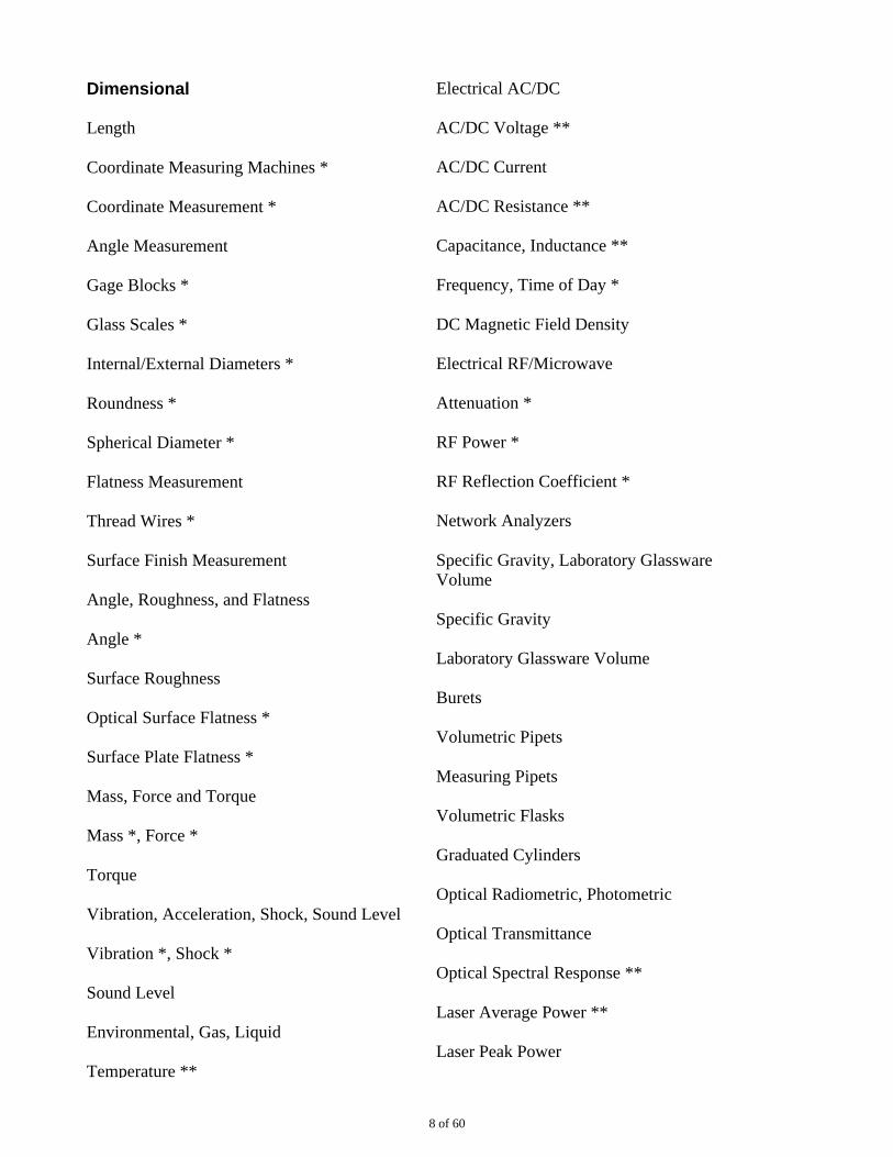
Dimensional
Length
Coordinate Measuring Machines *
Coordinate Measurement *
Angle Measurement
Gage Blocks *
Glass Scales *
Internal/External Diameters *
Roundness *
Spherical Diameter *
Flatness Measurement
Thread Wires *
Surface Finish Measurement
Angle, Roughness, and Flatness
Angle *
Surface Roughness
Optical Surface Flatness *
Surface Plate Flatness *
Mass, Force and Torque
Mass *, Force *
Torque
Vibration, Acceleration, Shock, Sound Level
Vibration *, Shock *
Sound Level
Environmental, Gas, Liquid
Temperature **
Electrical AC/DC
AC/DC Voltage **
AC/DC Current
AC/DC Resistance **
Capacitance, Inductance **
Frequency, Time of Day *
DC Magnetic Field Density
Electrical RF/Microwave
Attenuation *
RF Power *
RF Reflection Coefficient *
Network Analyzers
Specific Gravity, Laboratory GlasswareVolume
Specific Gravity
Laboratory Glassware Volume
Burets
Volumetric Pipets
Measuring Pipets
Volumetric Flasks
Graduated Cylinders
Optical Radiometric, Photometric
Optical Transmittance
Optical Spectral Response **
Laser Average Power **
Laser Peak Power
8 of 60
Temperature **
Fixed Point Temperature **
Humidity **
Pressure
Gas Flow **
Leak Rate **
Viscosity
LED Power
Ultraviolet Irradiance **
Illuminance **
Monochrometers **
X-Ray Film Density
Luminous Intensity **
HeNe Laser Frequency, Wavelength *
Mechanical
Length and Coordinate Measurement
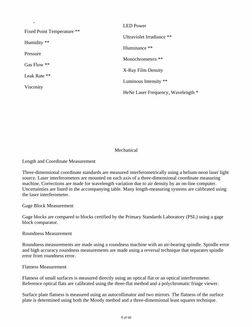
Three-dimensional coordinate standards are measured interferometrically using a helium-neon laser lightsource. Laser interferometers are mounted on each axis of a three-dimensional coordinate measuringmachine. Corrections are made for wavelength variation due to air density by an on-line computer.Uncertainties are listed in the accompanying table. Many length-measuring systems are calibrated usingthe laser interferometer.
Gage Block Measurement
Gage blocks are compared to blocks certified by the Primary Standards Laboratory (PSL) using a gageblock comparator.
Roundness Measurement
Roundness measurements are made using a roundness machine with an air-bearing spindle. Spindle errorand high accuracy roundness measurements are made using a reversal technique that separates spindleerror from roundness error.
Flatness Measurement
Flatness of small surfaces is measured directly using an optical flat or an optical interferometer.Reference optical flats are calibrated using the three-flat method and a polychromatic fringe viewer.
Surface plate flatness is measured using an autocollimator and two mirrors. The flatness of the surfaceplate is determined using both the Moody method and a three-dimensional least squares technique.
9 of 60
Angle Measurement
Small angles are measured using an autocollimator. The autocollimator is calibrated using a small-anglegenerator consisting of a pivot arm of known length and a set of certified gage blocks.
Large angles are measured using an autocollimator, a rotary table, an optical polygon, and angle gageblocks.
Surface Finish Measurement
Surface finish standards are measured using a profile-type surface finish analyzer. The surface finishanalyzer is calibrated using a lever arm calibrator and roughness standards calibrated by NIST.
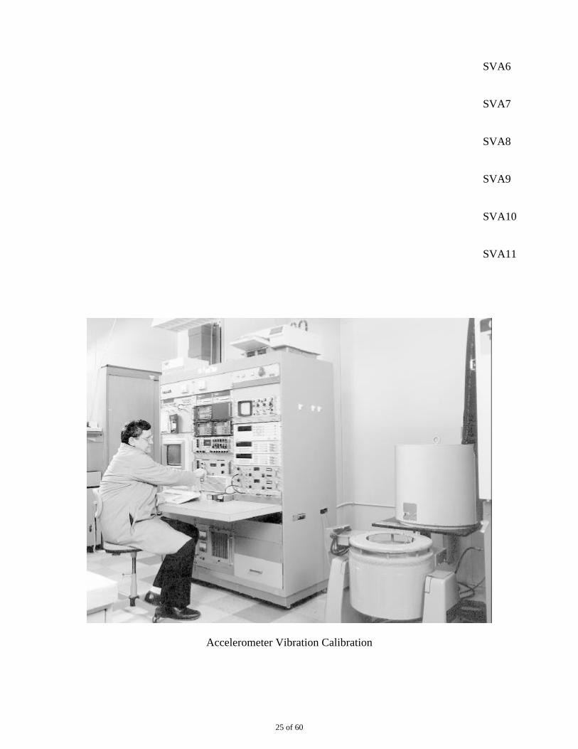
Vibration
Standard accelerometers are calibrated at NIST and certified for the transfer of its sensitivity to theVibration Systems transfer standard accelerometer. The vibration system transfers the sensitivity to otheraccelerometers. A control standard is measured on the vibration system to verify that the system isfunctioning properly.
Mechanical Shock
The shock standard accelerometer and accelerometers calibrated for shock levels above 10,000 g’s arecalibrated using a velocity change shock pulse generator. The shock pulses area and the time through aknown distance are captured to calculate the sensitivity using the velocity change method.Accelerometers calibrated for shock less than 10,000 g’s are calibrated in a back-to-back configurationon a hammer-activated shock pulse generator by comparison to the shock standard accelerometer.
Sound Level
Calibration of sound level is made by comparison of a sound level meter to a standard pistonphone thatis calibrated at NIST.
Mass Measurement
Mass measurements are made by comparison to master weights using seven precision balances. Themaster weights are calibrated through the NIST Mass Measurement Assurance Program.
Metrology also has the capability to perform extremely precise weighing on 1-2-3-5 decade progressionsover the range from 1 mg to 5 kg.
Force Measurement
Force transducers up to 2400-lbf capacity are measured using weight sets or dead weight testers whichare certified in force units in our Mass lab. Larger force devices are measured by comparison toNIST-calibrated proving rings using a universal force tester.
Torque Measurement
10 of 60
Torque transducers are measured using weights which are certified in force units in our Mass lab andlever arms of known length. The lever arms are calibrated on a coordinate measuring machine using ahelium-neon laser as a standard.
Laboratory Glassware Volume
Laboratory glassware volume is measured by the gravimetric method using precision balances anddistilled water.
Shelton CMM With Two-Dimensional CMM Calibration Artifact
11 of 60
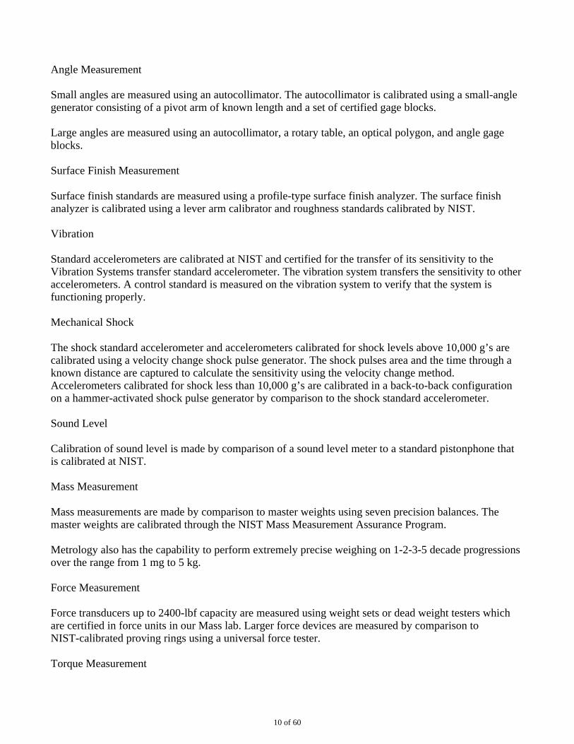
CMM With Video Edge Detection System
Dimensional Measurement Capability
12 of 60
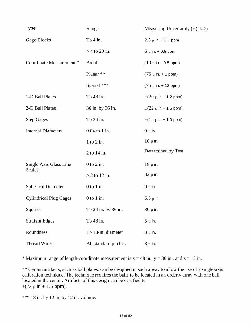
Type Range Measuring Uncertainty (± ) (k=2)
Gage Blocks To 4 in. 2.5 µ in. + 0.7 ppm
> 4 to 20 in. 6 µ in. + 0.5 ppm
Coordinate Measurement * Axial (10 µ in + 0.5 ppm)
Planar ** (75 µ in. + 1 ppm)
Spatial *** (75 µ in. + 12 ppm)
1-D Ball Plates To 48 in. ±(20 µ in + 1.2 ppm).
2-D Ball Plates 36 in. by 36 in. ±(22 µ in + 1.5 ppm).
Step Gages To 24 in. ±(15 µ in + 1.0 ppm).
Internal Diameters 0.04 to 1 in.
1 to 2 in.
2 to 14 in.
9 µ in.
10 µ in.
Determined by Test.
Single Axis Glass LineScales
0 to 2 in.
> 2 to 12 in.
18 µ in.
32 µ in.
Spherical Diameter 0 to 1 in. 9 µ in.
Cylindrical Plug Gages 0 to 1 in. 6.5 µ in.
Squares To 24 in. by 36 in. 30 µ in.
Straight Edges To 48 in. 5 µ in.
Roundness To 18-in. diameter 3 µ in.
Thread Wires All standard pitches 8 µ in.
* Maximum range of length-coordinate measurement is x = 48 in., y = 36 in., and z = 12 in.
** Certain artifacts, such as ball plates, can be designed in such a way to allow the use of a single-axiscalibration technique. The technique requires the balls to be located in an orderly array with one balllocated in the center. Artifacts of this design can be certified to ±(22 µ in + 1.5 ppm).
*** 18 in. by 12 in. by 12 in. volume.
13 of 60
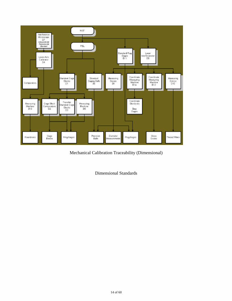
Mechanical Calibration Traceability (Dimensional)
Dimensional Standards
14 of 60
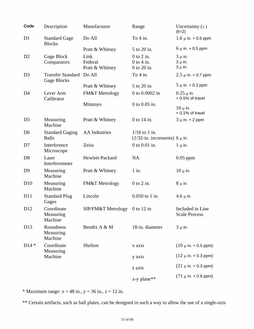
Code Description Manufacturer Range Uncertainty (± )(k=2)
D1 Standard GageBlocks
Do All
Pratt & Whitney
To 4 in.
5 to 20 in.
1.6 µ in. + 0.6 ppm
6 µ in. + 0.5 ppm
D2 Gage BlockComparators
Link Federal Pratt & Whitney
0 to 2 in. 0 to 4 in. 0 to 20 in.
3 µ in. 3 µ in. 3 µ in.
D3 Transfer StandardGage Blocks
Do All
Pratt & Whitney
To 4 in.
5 to 20 in.
2.5 µ in. + 0.7 ppm
5 µ in. + 0.3 ppm
D4 Lever ArmCalibrator
FM&T Metrology
Mitutoyo
0 to 0.0002 in
0 to 0.05 in.
0.25 µ in. + 0.5% of travel
10 µ in. + 0.1% of travel
D5 MeasuringMachine
Pratt & Whitney 0 to 14 in. 3 µ in. + 2 ppm
D6 Standard GagingBalls
AA Industries 1/16 to 1 in. (1/32-in. increments) 6 µ in.
D7 InterferenceMicroscope
Zeiss 0 to 0.01 in. 1 µ in.
D8 LaserInterferometer
Hewlett-Packard NA 0.05 ppm
D9 MeasuringMachine
Pratt & Whitney 1 in. 10 µ in.
D10 MeasuringMachine
FM&T Metrology 0 to 2 in. 8 µ in.
D11 Standard PlugGages
Lincoln 0.050 to 1 in. 4.6 µ in.
D12 CoordinateMeasuringMachine
SIP/FM&T Metrology 0 to 12 in Included in LineScale Process
D13 RoundnessMeasuringMachine
Bendix A & M 18-in. diameter 3 µ in.
D14 * CoordinateMeasuringMachine
Shelton x axis
y axis
z axis
x-y plane**
(10 µ in. + 0.5 ppm)
(12 µ in. + 0.3 ppm)
(21 µ in. + 0.3 ppm)
(71 µ in. + 0.6 ppm)
* Maximum range: x = 48 in., y = 36 in., z = 12 in.
** Certain artifacts, such as ball plates, can be designed in such a way to allow the use of a single-axis
15 of 60
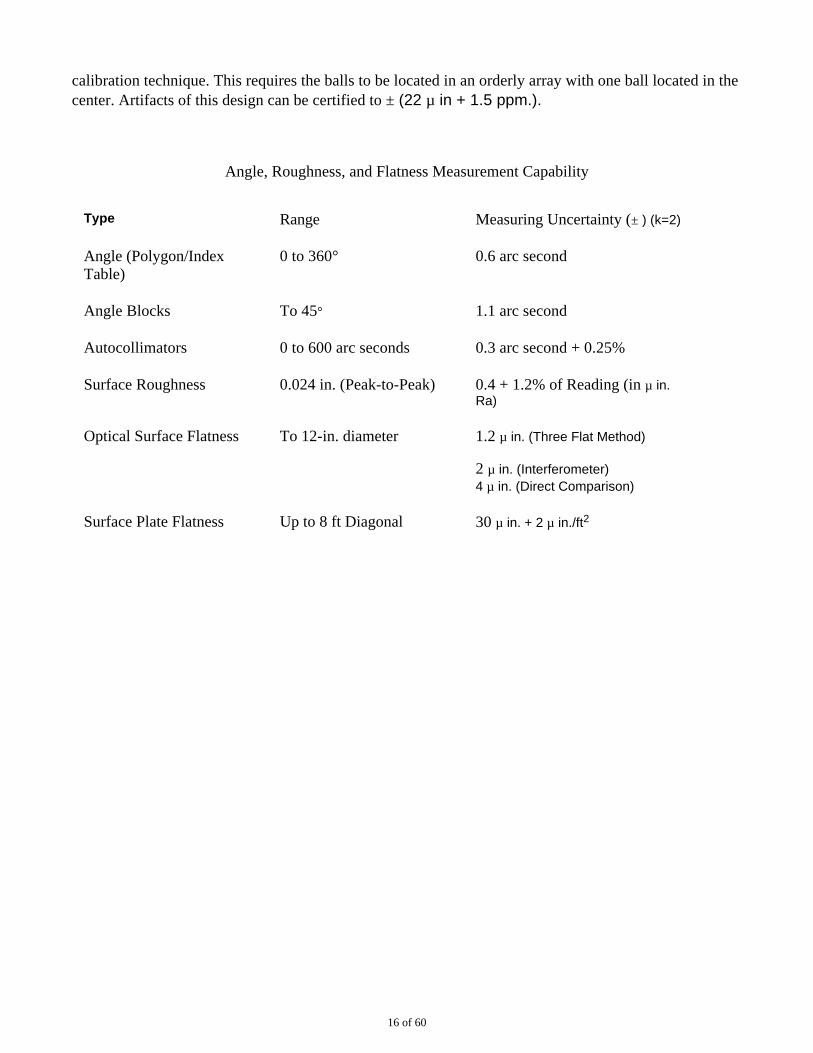
calibration technique. This requires the balls to be located in an orderly array with one ball located in thecenter. Artifacts of this design can be certified to ± (22 µ in + 1.5 ppm.).
Angle, Roughness, and Flatness Measurement Capability
Type Range Measuring Uncertainty (± ) (k=2)
Angle (Polygon/IndexTable)
0 to 360° 0.6 arc second
Angle Blocks To 45° 1.1 arc second
Autocollimators 0 to 600 arc seconds 0.3 arc second + 0.25%
Surface Roughness 0.024 in. (Peak-to-Peak) 0.4 + 1.2% of Reading (in µ in.Ra)
Optical Surface Flatness To 12-in. diameter 1.2 µ in. (Three Flat Method)
2 µ in. (Interferometer) 4 µ in. (Direct Comparison)
Surface Plate Flatness Up to 8 ft Diagonal 30 µ in. + 2 µ in./ft2
16 of 60
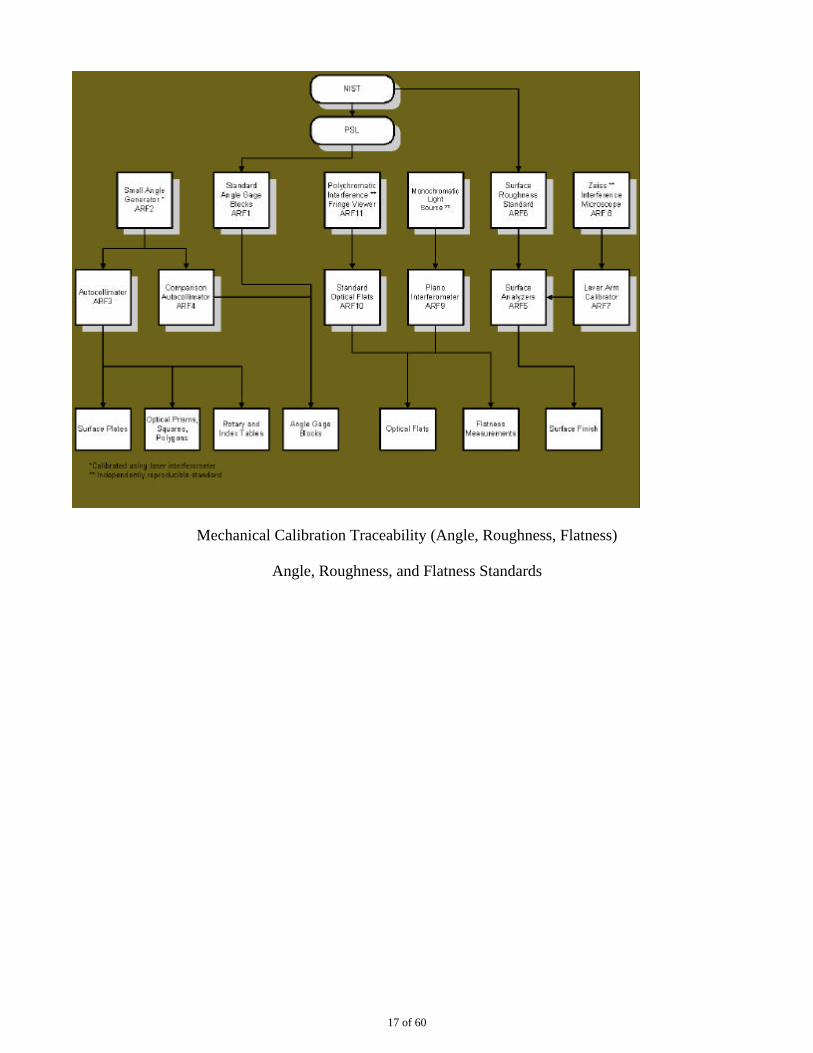
Mechanical Calibration Traceability (Angle, Roughness, Flatness)
Angle, Roughness, and Flatness Standards
17 of 60
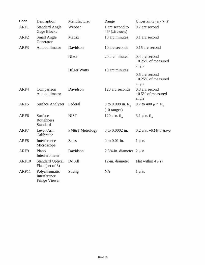
Code Description Manufacturer Range Uncertainty (± ) (k=2)
ARF1 Standard AngleGage Blocks
Webber 1 arc second to45° (16 blocks)
0.7 arc second
ARF2 Small AngleGenerator
Matrix 10 arc minutes 0.1 arc second
ARF3 Autocollimator Davidson
Nikon
Hilger Watts
10 arc seconds
20 arc minutes
10 arc minutes
0.15 arc second
0.4 arc second +0.25% of measuredangle
0.5 arc second +0.25% of measuredangle
ARF4 ComparisonAutocollimator
Davidson 120 arc seconds 0.3 arc second +0.5% of measuredangle
ARF5 Surface Analyzer Federal 0 to 0.008 in. Ra
(10 ranges)
0.7 to 400 µ in. Ra
ARF6 SurfaceRoughnessStandard
NIST 120 µ in. Ra 3.1 µ in. Ra
ARF7 Lever-ArmCalibrator
FM&T Metrology 0 to 0.0002 in. 0.2 µ in. +0.5% of travel
ARF8 InterferenceMicroscope
Zeiss 0 to 0.01 in. 1 µ in.
ARF9 PlanoInterferometer
Davidson 2 3/4-in. diameter 2 µ in.
ARF10 Standard OpticalFlats (set of 3)
Do All 12-in. diameter Flat within 4 µ in.
ARF11 PolychromaticInterferenceFringe Viewer
Strang NA 1 µ in.
18 of 60
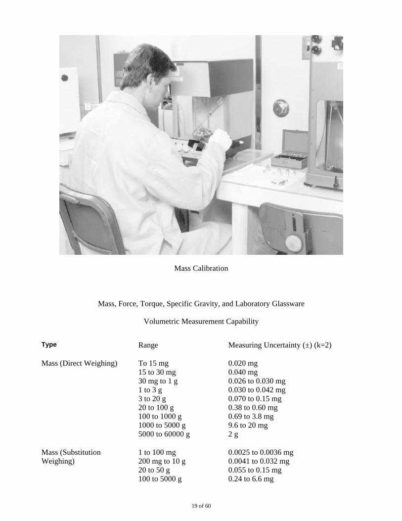
Mass Calibration
Mass, Force, Torque, Specific Gravity, and Laboratory Glassware
Volumetric Measurement Capability
Type Range Measuring Uncertainty (±) (k=2)
Mass (Direct Weighing) To 15 mg 15 to 30 mg 30 mg to 1 g 1 to 3 g 3 to 20 g 20 to 100 g 100 to 1000 g 1000 to 5000 g 5000 to 60000 g
0.020 mg 0.040 mg 0.026 to 0.030 mg 0.030 to 0.042 mg 0.070 to 0.15 mg 0.38 to 0.60 mg 0.69 to 3.8 mg 9.6 to 20 mg 2 g
Mass (SubstitutionWeighing)
1 to 100 mg 200 mg to 10 g 20 to 50 g 100 to 5000 g
0.0025 to 0.0036 mg 0.0041 to 0.032 mg 0.055 to 0.15 mg 0.24 to 6.6 mg
19 of 60
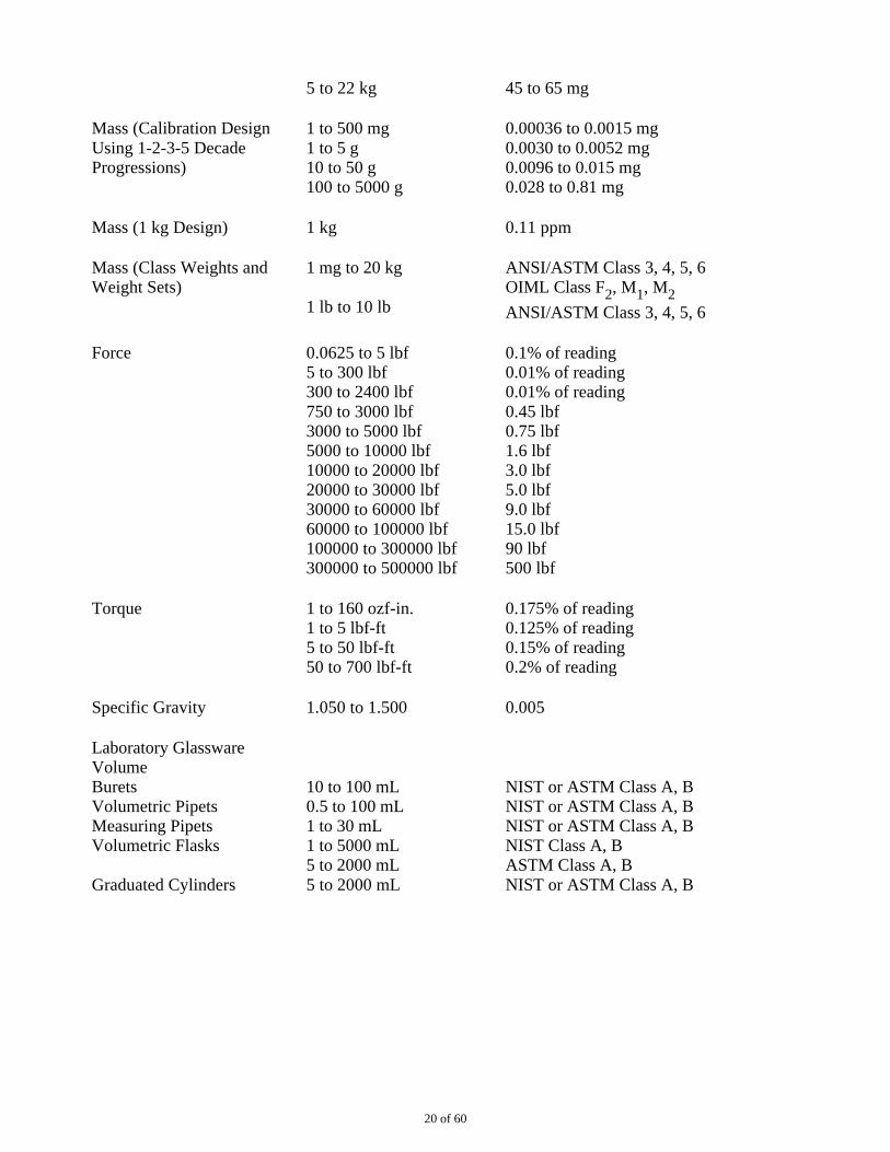
5 to 22 kg 45 to 65 mg
Mass (Calibration Design Using 1-2-3-5 DecadeProgressions)
1 to 500 mg 1 to 5 g 10 to 50 g 100 to 5000 g
0.00036 to 0.0015 mg 0.0030 to 0.0052 mg 0.0096 to 0.015 mg 0.028 to 0.81 mg
Mass (1 kg Design) 1 kg 0.11 ppm
Mass (Class Weights andWeight Sets)
1 mg to 20 kg
1 lb to 10 lb
ANSI/ASTM Class 3, 4, 5, 6 OIML Class F2, M1, M2
ANSI/ASTM Class 3, 4, 5, 6
Force 0.0625 to 5 lbf 5 to 300 lbf 300 to 2400 lbf 750 to 3000 lbf 3000 to 5000 lbf 5000 to 10000 lbf 10000 to 20000 lbf 20000 to 30000 lbf 30000 to 60000 lbf 60000 to 100000 lbf 100000 to 300000 lbf 300000 to 500000 lbf
0.1% of reading 0.01% of reading 0.01% of reading 0.45 lbf 0.75 lbf 1.6 lbf 3.0 lbf 5.0 lbf 9.0 lbf 15.0 lbf 90 lbf 500 lbf
Torque 1 to 160 ozf-in. 1 to 5 lbf-ft 5 to 50 lbf-ft 50 to 700 lbf-ft
0.175% of reading 0.125% of reading 0.15% of reading 0.2% of reading
Specific Gravity 1.050 to 1.500 0.005
Laboratory GlasswareVolume Burets Volumetric Pipets Measuring Pipets Volumetric Flasks
Graduated Cylinders
10 to 100 mL 0.5 to 100 mL 1 to 30 mL 1 to 5000 mL 5 to 2000 mL 5 to 2000 mL
NIST or ASTM Class A, B NIST or ASTM Class A, B NIST or ASTM Class A, B NIST Class A, B ASTM Class A, B NIST or ASTM Class A, B
20 of 60
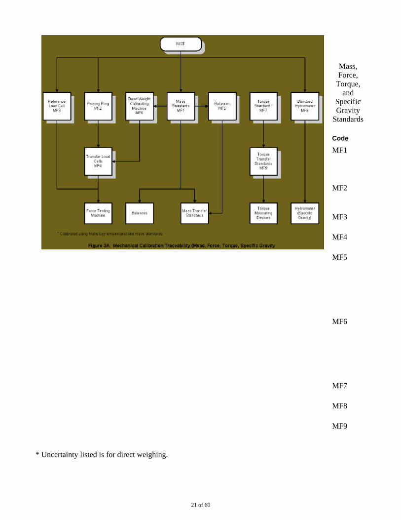
Mass,Force,
Torque,and
SpecificGravity
Standards
Code
MF1
MF2
MF3
MF4
MF5
MF6
MF7
MF8
MF9
* Uncertainty listed is for direct weighing.
21 of 60
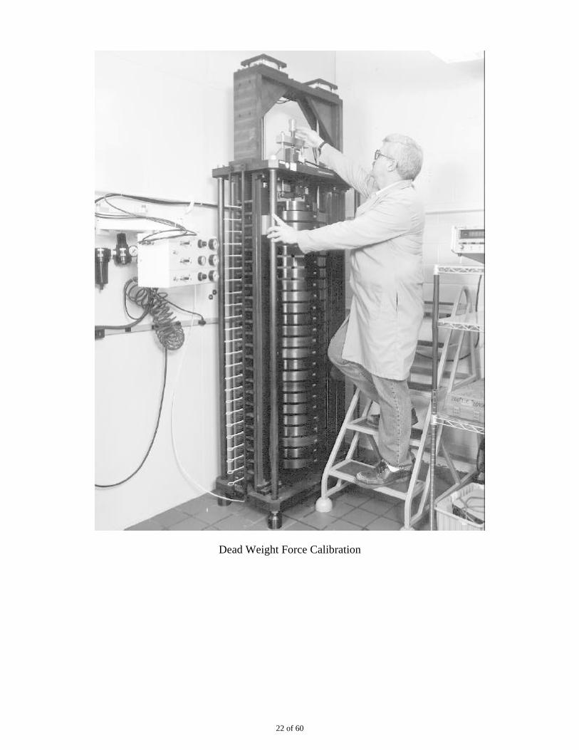
Dead Weight Force Calibration
22 of 60
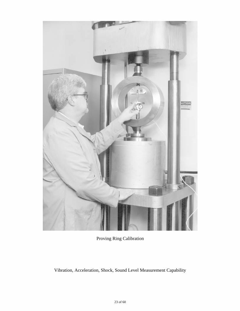
Proving Ring Calibration
Vibration, Acceleration, Shock, Sound Level Measurement Capability
23 of 60
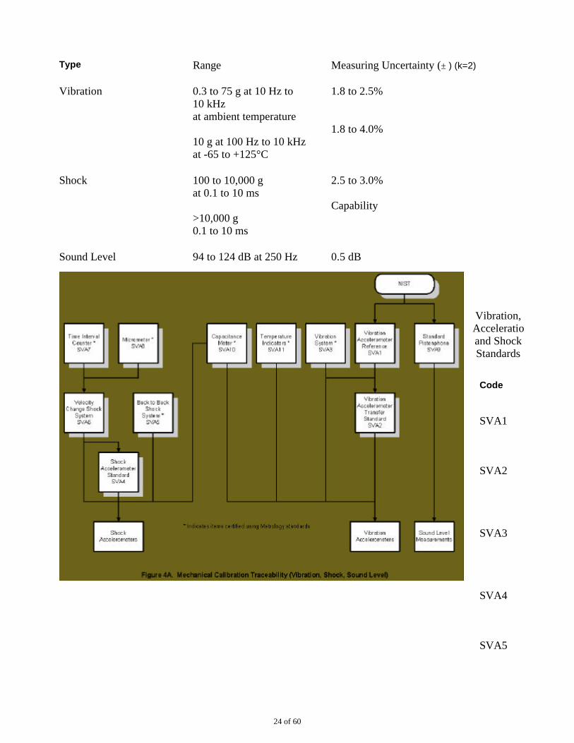
Type Range Measuring Uncertainty (± ) (k=2)
Vibration 0.3 to 75 g at 10 Hz to10 kHz at ambient temperature
10 g at 100 Hz to 10 kHz at -65 to +125°C
1.8 to 2.5%
1.8 to 4.0%
Shock 100 to 10,000 g at 0.1 to 10 ms
>10,000 g 0.1 to 10 ms
2.5 to 3.0%
Capability
Sound Level 94 to 124 dB at 250 Hz 0.5 dB
Vibration,Acceleration,and ShockStandards
Code
SVA1
SVA2
SVA3
SVA4
SVA5
24 of 60
SVA6
SVA7
SVA8
SVA9
SVA10
SVA11
Accelerometer Vibration Calibration
25 of 60
ENVIRONMENTAL, GAS, LIQUID
Temperature
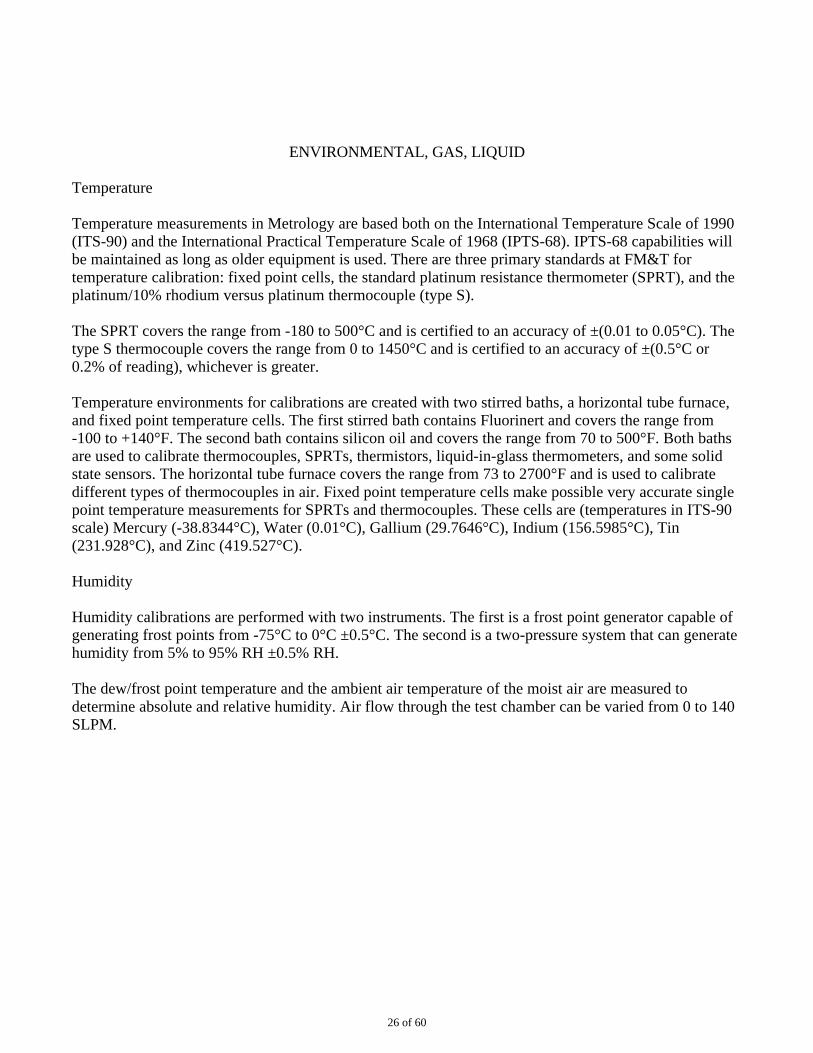
Temperature measurements in Metrology are based both on the International Temperature Scale of 1990(ITS-90) and the International Practical Temperature Scale of 1968 (IPTS-68). IPTS-68 capabilities willbe maintained as long as older equipment is used. There are three primary standards at FM&T fortemperature calibration: fixed point cells, the standard platinum resistance thermometer (SPRT), and theplatinum/10% rhodium versus platinum thermocouple (type S).
The SPRT covers the range from -180 to 500°C and is certified to an accuracy of ±(0.01 to 0.05°C). Thetype S thermocouple covers the range from 0 to 1450°C and is certified to an accuracy of ±(0.5°C or0.2% of reading), whichever is greater.
Temperature environments for calibrations are created with two stirred baths, a horizontal tube furnace,and fixed point temperature cells. The first stirred bath contains Fluorinert and covers the range from-100 to +140°F. The second bath contains silicon oil and covers the range from 70 to 500°F. Both bathsare used to calibrate thermocouples, SPRTs, thermistors, liquid-in-glass thermometers, and some solidstate sensors. The horizontal tube furnace covers the range from 73 to 2700°F and is used to calibratedifferent types of thermocouples in air. Fixed point temperature cells make possible very accurate singlepoint temperature measurements for SPRTs and thermocouples. These cells are (temperatures in ITS-90scale) Mercury (-38.8344°C), Water (0.01°C), Gallium (29.7646°C), Indium (156.5985°C), Tin(231.928°C), and Zinc (419.527°C).
Humidity
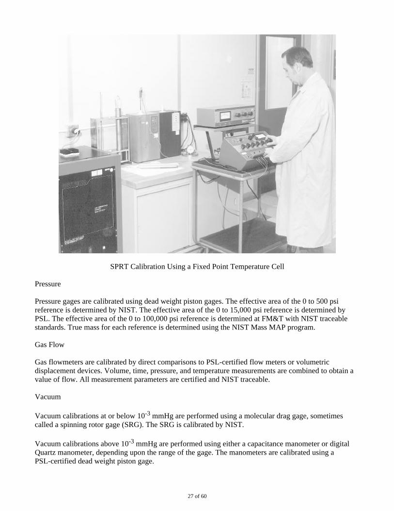
Humidity calibrations are performed with two instruments. The first is a frost point generator capable ofgenerating frost points from -75°C to 0°C ±0.5°C. The second is a two-pressure system that can generatehumidity from 5% to 95% RH ±0.5% RH.
The dew/frost point temperature and the ambient air temperature of the moist air are measured todetermine absolute and relative humidity. Air flow through the test chamber can be varied from 0 to 140SLPM.
26 of 60
SPRT Calibration Using a Fixed Point Temperature Cell
Pressure
Pressure gages are calibrated using dead weight piston gages. The effective area of the 0 to 500 psireference is determined by NIST. The effective area of the 0 to 15,000 psi reference is determined byPSL. The effective area of the 0 to 100,000 psi reference is determined at FM&T with NIST traceablestandards. True mass for each reference is determined using the NIST Mass MAP program.
Gas Flow
Gas flowmeters are calibrated by direct comparisons to PSL-certified flow meters or volumetricdisplacement devices. Volume, time, pressure, and temperature measurements are combined to obtain avalue of flow. All measurement parameters are certified and NIST traceable.
Vacuum
Vacuum calibrations at or below 10-3 mmHg are performed using a molecular drag gage, sometimescalled a spinning rotor gage (SRG). The SRG is calibrated by NIST.
Vacuum calibrations above 10-3 mmHg are performed using either a capacitance manometer or digitalQuartz manometer, depending upon the range of the gage. The manometers are calibrated using aPSL-certified dead weight piston gage.
27 of 60
Gas Leaks
Gas leak devices are calibrated by making direct comparisons to PSL-certified leaks on a massspectrometer or using the pressure, volume, temperature (PVT) technique. All measurement parametersof the PVT technique are certified and NIST traceable. A precision gas analyzer is used to evaluate thecomposition of the leak gas.
Viscosity
Viscometers are calibrated using standard viscosity oils obtained from the Cannon Instrument Company,an approved CCL source.
Humidity Calibration Using the Two-Pressure Method
Environmental Measurement Capability (Temperature, Humidity)
28 of 60
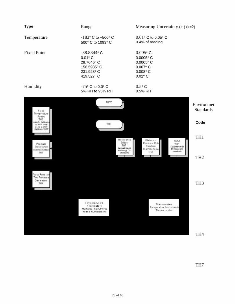
Type Range Measuring Uncertainty (± ) (k=2)
Temperature -183° C to +500° C 500° C to 1093° C
0.01° C to 0.05° C 0.4% of reading
Fixed Point -38.8344° C 0.01° C 29.7646° C 156.5985° C 231.928° C 419.527° C
0.005° C 0.0005° C 0.0005° C 0.007° C 0.008° C 0.01° C
Humidity -75° C to 0.0° C 5% RH to 95% RH
0.5° C 0.5% RH
EnvironmentalStandards
Code
TH1
TH2
TH3
TH4
TH7
29 of 60
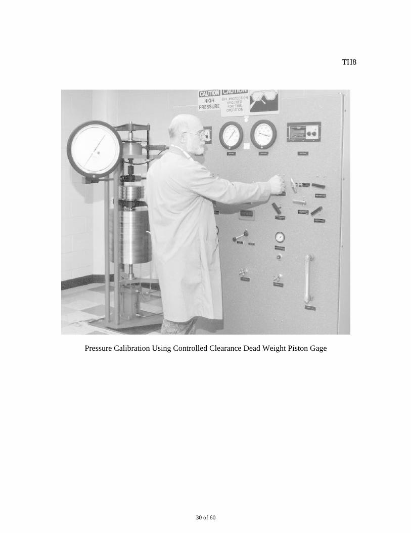
TH8
Pressure Calibration Using Controlled Clearance Dead Weight Piston Gage
30 of 60
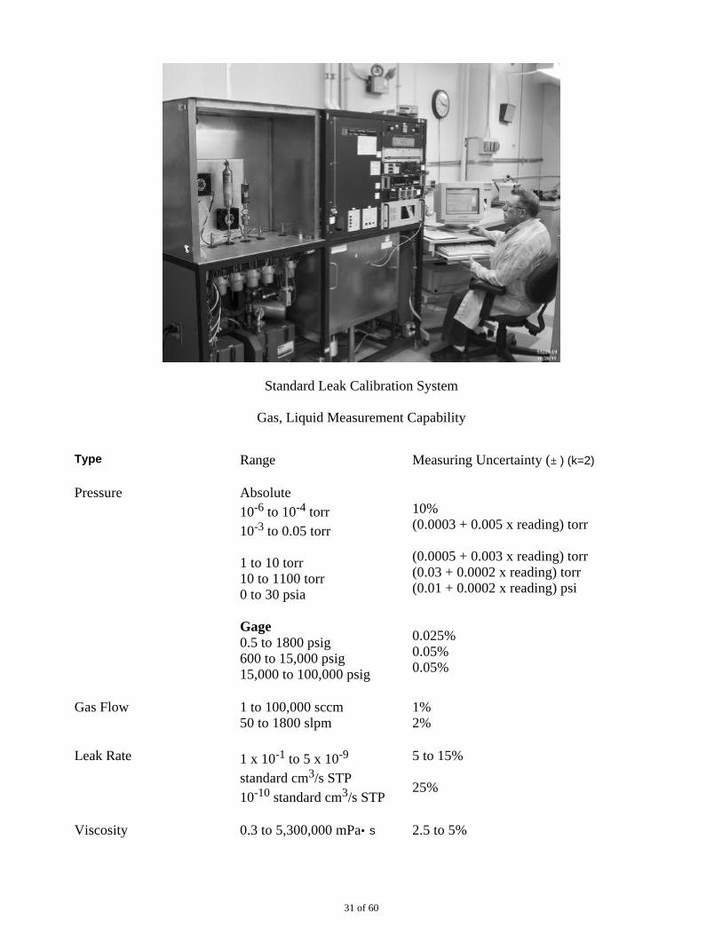
Standard Leak Calibration System
Gas, Liquid Measurement Capability
Type Range Measuring Uncertainty (± ) (k=2)
Pressure Absolute 10-6 to 10-4 torr 10-3 to 0.05 torr
1 to 10 torr 10 to 1100 torr 0 to 30 psia
Gage 0.5 to 1800 psig 600 to 15,000 psig 15,000 to 100,000 psig
10% (0.0003 + 0.005 x reading) torr
(0.0005 + 0.003 x reading) torr (0.03 + 0.0002 x reading) torr (0.01 + 0.0002 x reading) psi
0.025% 0.05% 0.05%
Gas Flow 1 to 100,000 sccm 50 to 1800 slpm
1% 2%
Leak Rate 1 x 10⁻¹ to 5 x 10⁻⁹ standard cm3/s STP 10-10 standard cm3/s STP
5 to 15%
25%
Viscosity 0.3 to 5,300,000 mPa• s 2.5 to 5%
31 of 60
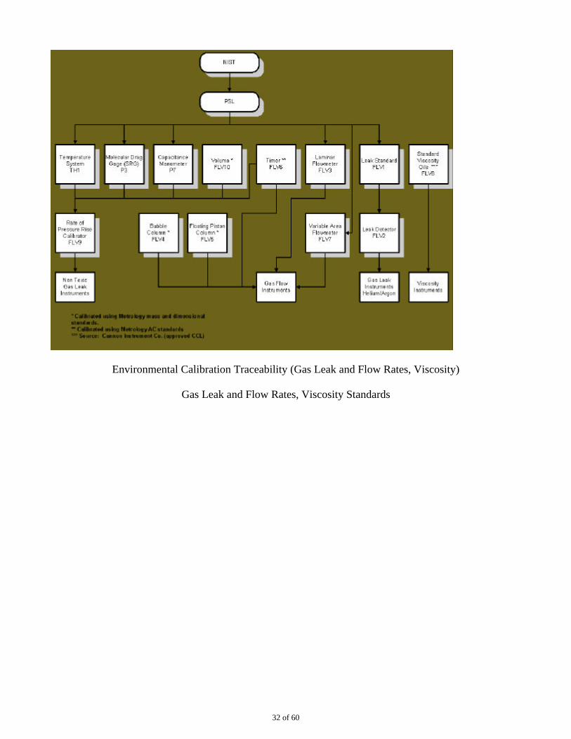
Environmental Calibration Traceability (Gas Leak and Flow Rates, Viscosity)
Gas Leak and Flow Rates, Viscosity Standards
32 of 60
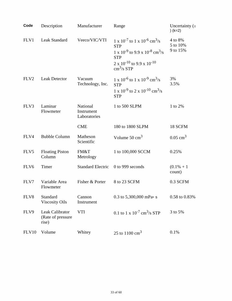
Code Description Manufacturer Range Uncertainty (±) (k=2)
FLV1 Leak Standard Veeco/VIC/VTI 1 x 10⁻⁷ to 1 x 10⁻⁶ cm3/sSTP 1 x 10⁻⁹ to 9.9 x 10⁻⁸ cm3/sSTP 2 x 10⁻¹⁰ to 9.9 x 10⁻¹⁰
cm3/s STP
4 to 8% 5 to 10% 9 to 15%
FLV2 Leak Detector VacuumTechnology, Inc.
1 x 10⁻⁶ to 1 x 10⁻⁹ cm3/sSTP 1 x 10⁻⁹ to 2 x 10⁻¹⁰ cm3/sSTP
3% 3.5%
FLV3 LaminarFlowmeter
NationalInstrumentLaboratories
CME
1 to 500 SLPM
180 to 1800 SLPM
1 to 2%
18 SCFM
FLV4 Bubble Column MathesonScientific
Volume 50 cm3 0.05 cm3
FLV5 Floating PistonColumn
FM&TMetrology
1 to 100,000 SCCM 0.25%
FLV6 Timer Standard Electric 0 to 999 seconds (0.1% + 1count)
FLV7 Variable AreaFlowmeter
Fisher & Porter 8 to 23 SCFM 0.3 SCFM
FLV8 StandardViscosity Oils
CannonInstrument
0.3 to 5,300,000 mPa• s 0.58 to 0.83%
FLV9 Leak Calibrator(Rate of pressurerise)
VTI 0.1 to 1 x 10⁻⁷ cm3/s STP 3 to 5%
FLV10 Volume Whitey 25 to 1100 cm3 0.1%
33 of 60
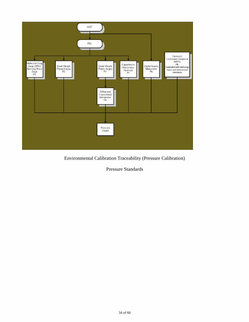
Environmental Calibration Traceability (Pressure Calibration)
Pressure Standards
34 of 60
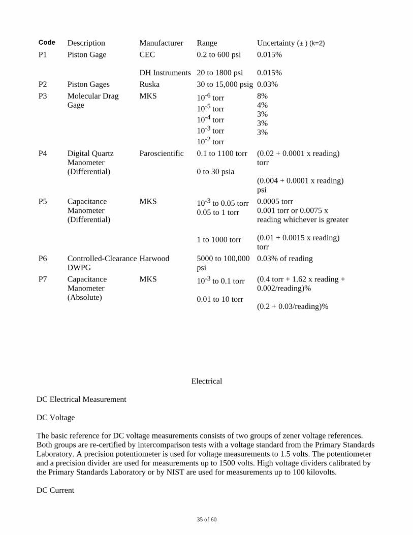
Code Description Manufacturer Range Uncertainty (± ) (k=2)
P1 Piston Gage CEC
DH Instruments
0.2 to 600 psi
20 to 1800 psi
0.015%
0.015%
P2 Piston Gages Ruska 30 to 15,000 psig 0.03%
P3 Molecular DragGage
MKS 10-6 torr 10-5 torr 10-4 torr 10-3 torr 10-2 torr
8% 4% 3% 3% 3%
P4 Digital QuartzManometer(Differential)
Paroscientific 0.1 to 1100 torr
0 to 30 psia
(0.02 + 0.0001 x reading)torr
(0.004 + 0.0001 x reading)psi
P5 CapacitanceManometer(Differential)
MKS 10-3 to 0.05 torr 0.05 to 1 torr
1 to 1000 torr
0.0005 torr 0.001 torr or 0.0075 xreading whichever is greater
(0.01 + 0.0015 x reading)torr
P6 Controlled-ClearanceDWPG
Harwood 5000 to 100,000psi
0.03% of reading
P7 CapacitanceManometer(Absolute)
MKS 10-3 to 0.1 torr
0.01 to 10 torr
(0.4 torr + 1.62 x reading +0.002/reading)%
(0.2 + 0.03/reading)%
Electrical
DC Electrical Measurement
DC Voltage
The basic reference for DC voltage measurements consists of two groups of zener voltage references.Both groups are re-certified by intercomparison tests with a voltage standard from the Primary StandardsLaboratory. A precision potentiometer is used for voltage measurements to 1.5 volts. The potentiometerand a precision divider are used for measurements up to 1500 volts. High voltage dividers calibrated bythe Primary Standards Laboratory or by NIST are used for measurements up to 100 kilovolts.
DC Current
35 of 60
Measurements of current up to 2 amperes are made using resistance and voltage standards. Shuntscalibrated by the Primary Standards Laboratory are used for current measurements from 2 amperes to 300amperes.
DC Resistance
The reference for resistance measurements is two groups of standard resistors, ranging from 0.001 ohmto 100 megohms, which are certified by the Primary Standards Laboratory. These resistors, a double ratioset and a precision bridge, are used for resistance measurements to 100 megohms. Above 100 megohmsand up to 10 teraohms, resistance measurements are accomplished using either a wheatstone bridge or ateraohmmeter.
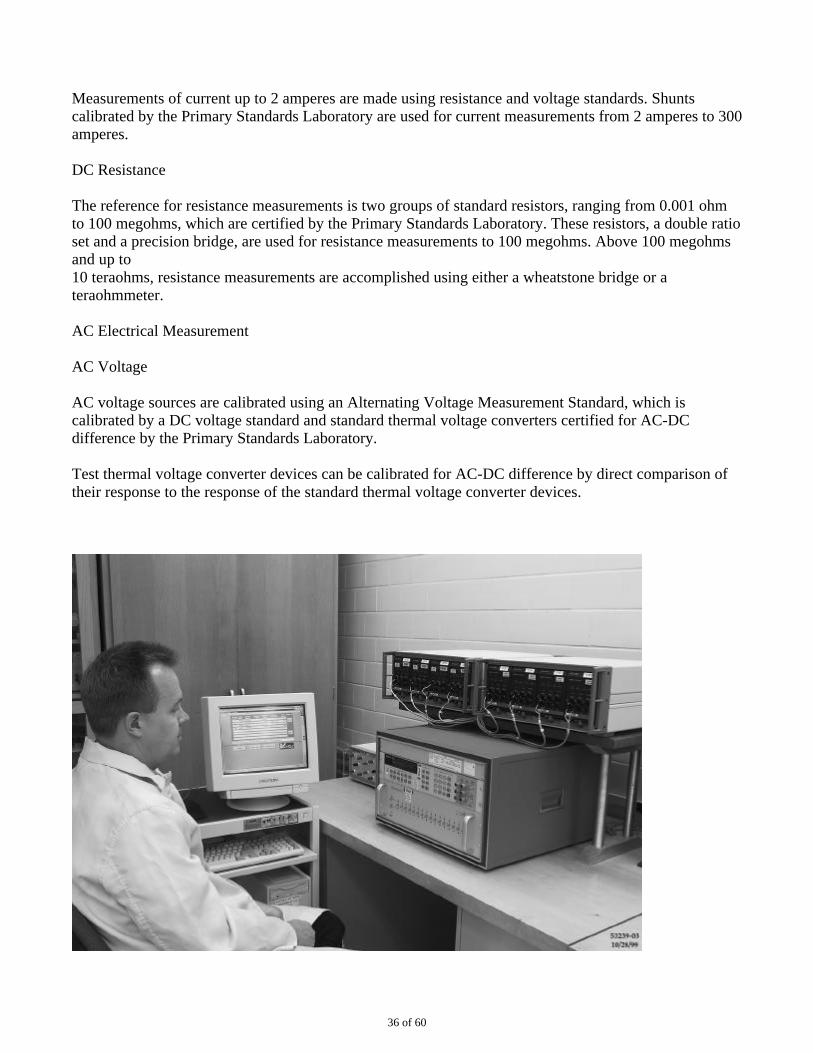
AC Electrical Measurement
AC Voltage
AC voltage sources are calibrated using an Alternating Voltage Measurement Standard, which iscalibrated by a DC voltage standard and standard thermal voltage converters certified for AC-DCdifference by the Primary Standards Laboratory.
Test thermal voltage converter devices can be calibrated for AC-DC difference by direct comparison oftheir response to the response of the standard thermal voltage converter devices.
36 of 60
DC Voltage Inter-comparison
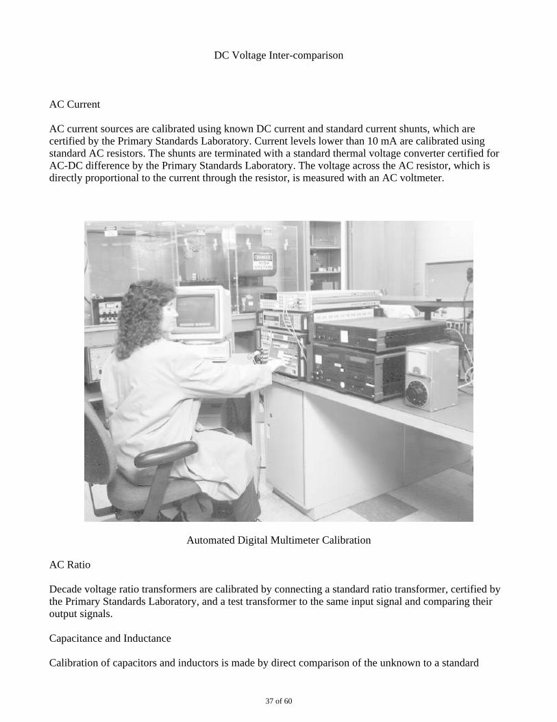
AC Current
AC current sources are calibrated using known DC current and standard current shunts, which arecertified by the Primary Standards Laboratory. Current levels lower than 10 mA are calibrated usingstandard AC resistors. The shunts are terminated with a standard thermal voltage converter certified forAC-DC difference by the Primary Standards Laboratory. The voltage across the AC resistor, which isdirectly proportional to the current through the resistor, is measured with an AC voltmeter.
Automated Digital Multimeter Calibration
AC Ratio
Decade voltage ratio transformers are calibrated by connecting a standard ratio transformer, certified bythe Primary Standards Laboratory, and a test transformer to the same input signal and comparing theiroutput signals.
Capacitance and Inductance
Calibration of capacitors and inductors is made by direct comparison of the unknown to a standard
37 of 60
capacitor or standard inductor calibrated by the Primary Standards Laboratory. Depending on accuracyand frequency, the comparison is made on a transformer ratio arm bridge (for capacitance only) or on oneof three different LCR meters.
The measurement uncertainties vary with value and frequency. Capacitance uncertainties range upwardfrom ±0.02%. Inductance uncertainties range upward from ±0.03%.
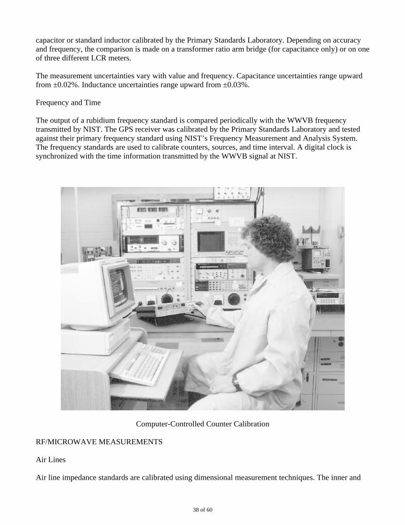
Frequency and Time
The output of a rubidium frequency standard is compared periodically with the WWVB frequencytransmitted by NIST. The GPS receiver was calibrated by the Primary Standards Laboratory and testedagainst their primary frequency standard using NIST’s Frequency Measurement and Analysis System.The frequency standards are used to calibrate counters, sources, and time interval. A digital clock issynchronized with the time information transmitted by the WWVB signal at NIST.
Computer-Controlled Counter Calibration
RF/MICROWAVE MEASUREMENTS
Air Lines
Air line impedance standards are calibrated using dimensional measurement techniques. The inner and
38 of 60
outer conductor’s diameters are measured using air gages and the lengths are measured using a lengthmeasurement system by comparison to gage blocks of similar lengths. The dimensional measurementsare used to calculate the impedance and electrical length.
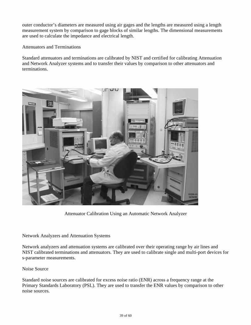
Attenuators and Terminations
Standard attenuators and terminations are calibrated by NIST and certified for calibrating Attenuationand Network Analyzer systems and to transfer their values by comparison to other attenuators andterminations.
Attenuator Calibration Using an Automatic Network Analyzer
Network Analyzers and Attenuation Systems
Network analyzers and attenuation systems are calibrated over their operating range by air lines andNIST calibrated terminations and attenuators. They are used to calibrate single and multi-port devices fors-parameter measurements.
Noise Source
Standard noise sources are calibrated for excess noise ratio (ENR) across a frequency range at thePrimary Standards Laboratory (PSL). They are used to transfer the ENR values by comparison to othernoise sources.
39 of 60
Thermistor Mounts
Standard thermistor mounts are calibrated by NIST and certified for calibrating a Power Meter/SensorCalibration system and transferring the calibration factor values by comparison to other thermistormounts.
Probe Station
The probe station is used to measure chip devices and wafer components. NIST reference materials areavailable for comparisons. The probes are 100 µm to 3000 µm widths, GS, SG, and Ground SignalGround with cal substrates.
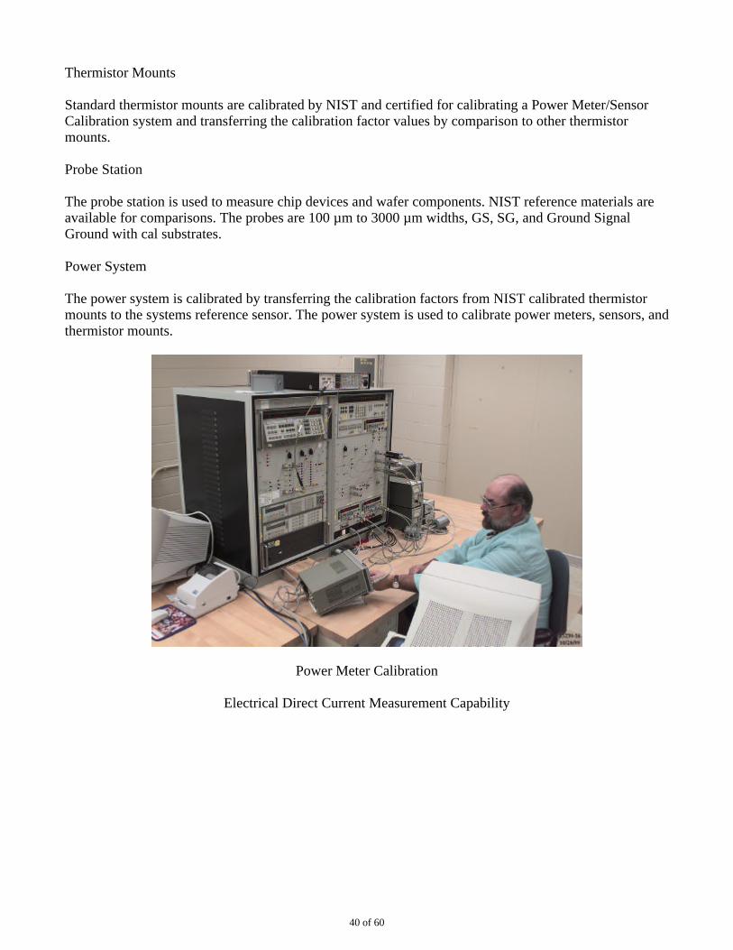
Power System
The power system is calibrated by transferring the calibration factors from NIST calibrated thermistormounts to the systems reference sensor. The power system is used to calibrate power meters, sensors, andthermistor mounts.
Power Meter Calibration
Electrical Direct Current Measurement Capability
40 of 60
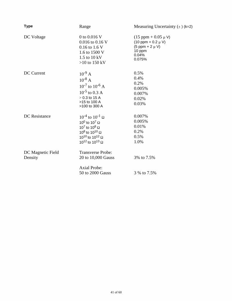
Type Range Measuring Uncertainty (± ) (k=2)
DC Voltage 0 to 0.016 V 0.016 to 0.16 V 0.16 to 1.6 V 1.6 to 1500 V 1.5 to 10 kV >10 to 150 kV
(15 ppm + 0.05 µ V) (10 ppm + 0.2 µ V) (5 ppm + 2 µ V) 10 ppm 0.04% 0.075%
DC Current 10-9 A 10-8 A 10-7 to 10-6 A 10-5 to 0.3 A > 0.3 to 15 A >15 to 100 A >100 to 300 A
0.5% 0.4% 0.2% 0.005% 0.007% 0.02% 0.03%
DC Resistance 10-4 to 10-1 Ω 100 to 107 Ω 107 to 108 Ω 108 to 1010 Ω 1010 to 1012 Ω 1012 to 1013 Ω
0.007% 0.005% 0.01% 0.2% 0.5% 1.0%
DC Magnetic FieldDensity
Transverse Probe: 20 to 10,000 Gauss
Axial Probe: 50 to 2000 Gauss
3% to 7.5%
3 % to 7.5%
41 of 60
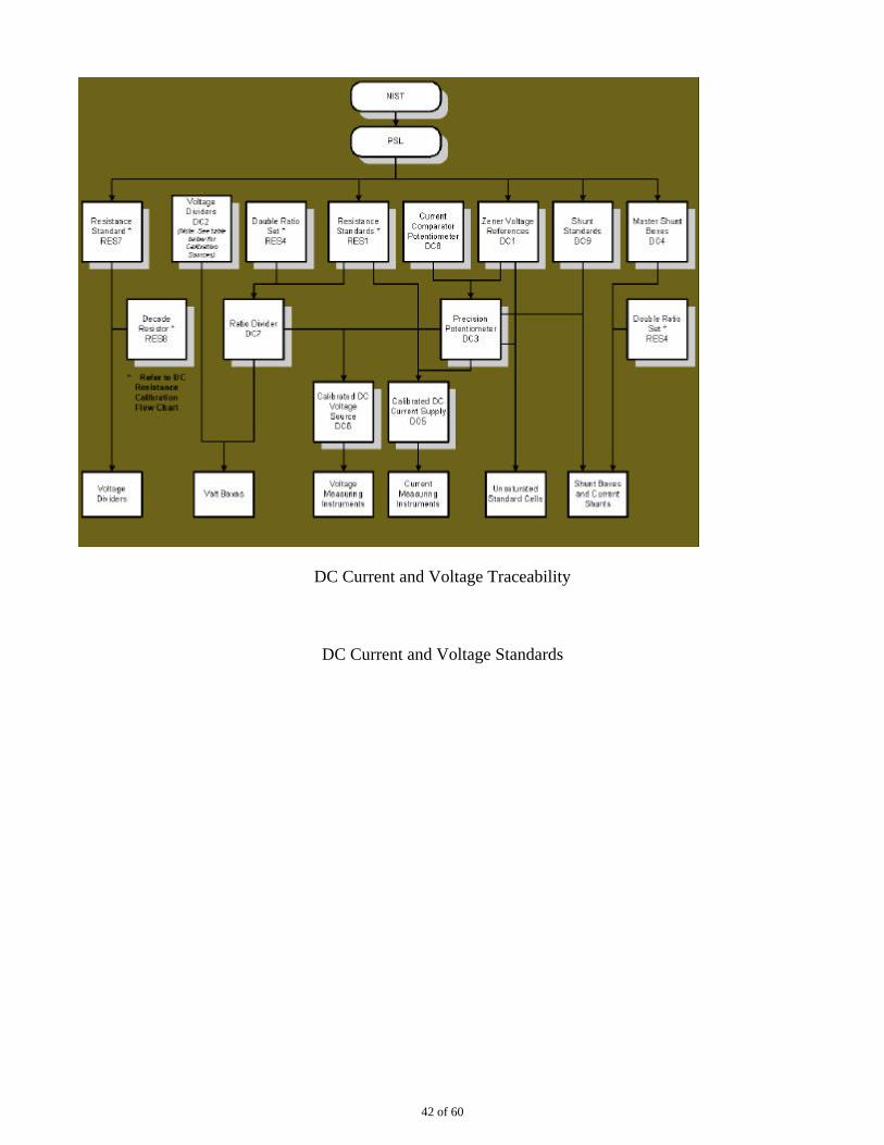
DC Current and Voltage Traceability
DC Current and Voltage Standards
42 of 60
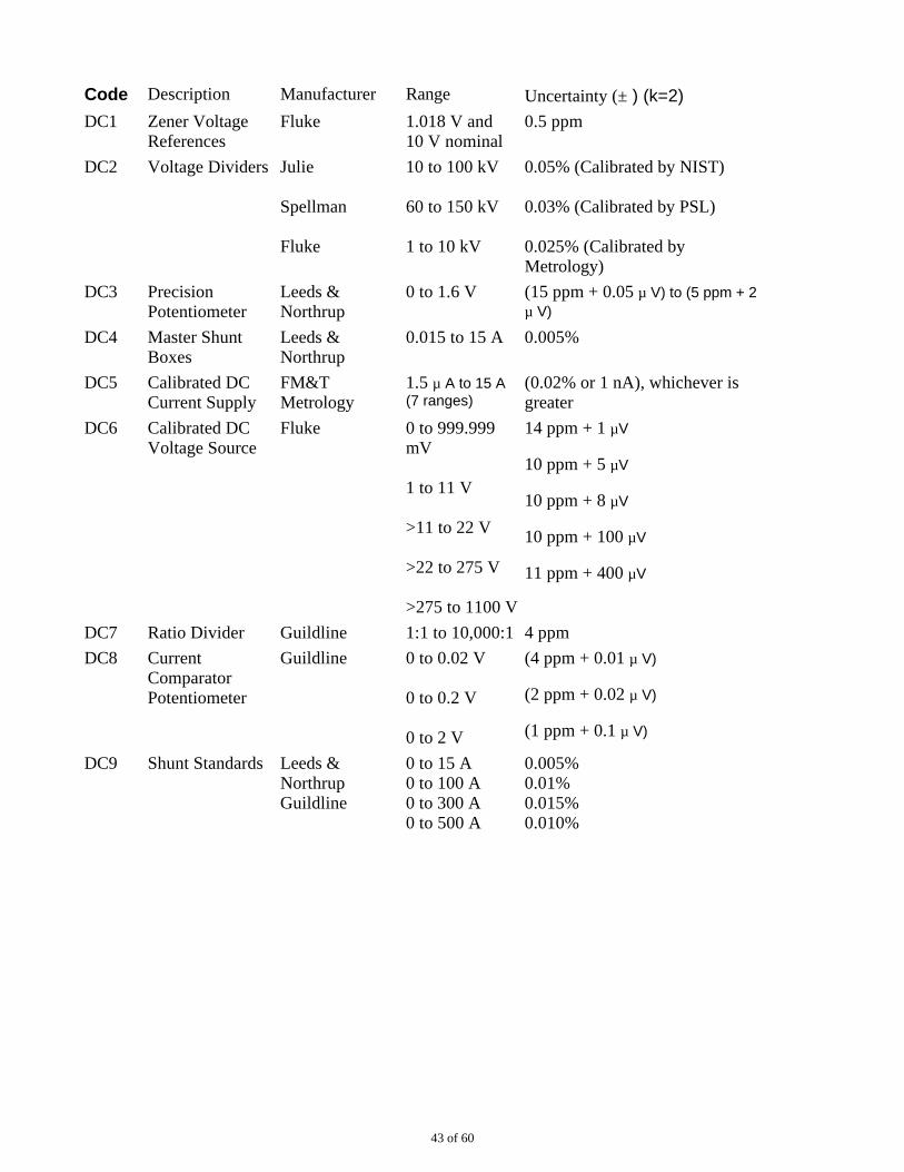
Code Description Manufacturer Range Uncertainty (± ) (k=2)
DC1 Zener VoltageReferences
Fluke 1.018 V and 10 V nominal
0.5 ppm
DC2 Voltage Dividers Julie
Spellman
Fluke
10 to 100 kV
60 to 150 kV
1 to 10 kV
0.05% (Calibrated by NIST)
0.03% (Calibrated by PSL)
0.025% (Calibrated byMetrology)
DC3 PrecisionPotentiometer
Leeds &Northrup
0 to 1.6 V (15 ppm + 0.05 µ V) to (5 ppm + 2µ V)
DC4 Master ShuntBoxes
Leeds &Northrup
0.015 to 15 A 0.005%
DC5 Calibrated DCCurrent Supply
FM&TMetrology
1.5 µ A to 15 A (7 ranges)
(0.02% or 1 nA), whichever isgreater
DC6 Calibrated DCVoltage Source
Fluke 0 to 999.999mV
1 to 11 V
>11 to 22 V
>22 to 275 V
>275 to 1100 V
14 ppm + 1 µV
10 ppm + 5 µV
10 ppm + 8 µV
10 ppm + 100 µV
11 ppm + 400 µV
DC7 Ratio Divider Guildline 1:1 to 10,000:1 4 ppm
DC8 CurrentComparatorPotentiometer
Guildline 0 to 0.02 V
0 to 0.2 V
0 to 2 V
(4 ppm + 0.01 µ V)
(2 ppm + 0.02 µ V)
(1 ppm + 0.1 µ V)
DC9 Shunt Standards Leeds &Northrup Guildline
0 to 15 A 0 to 100 A 0 to 300 A 0 to 500 A
0.005% 0.01% 0.015% 0.010%
43 of 60
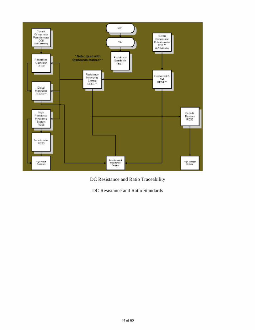
DC Resistance and Ratio Traceability
DC Resistance and Ratio Standards
44 of 60
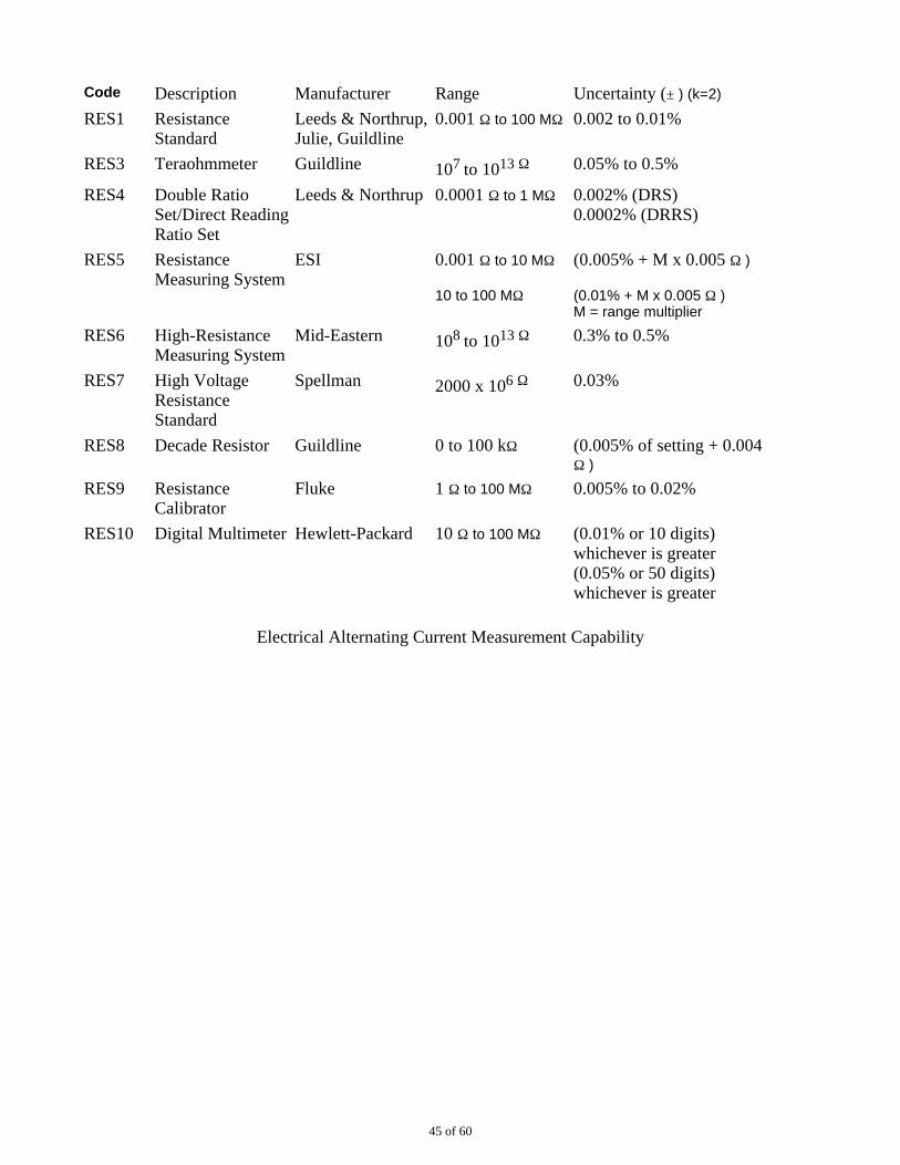
Code Description Manufacturer Range Uncertainty (± ) (k=2)
RES1 ResistanceStandard
Leeds & Northrup,Julie, Guildline
0.001 Ω to 100 MΩ 0.002 to 0.01%
RES3 Teraohmmeter Guildline 107 to 1013 Ω 0.05% to 0.5%
RES4 Double RatioSet/Direct ReadingRatio Set
Leeds & Northrup 0.0001 Ω to 1 MΩ 0.002% (DRS) 0.0002% (DRRS)
RES5 ResistanceMeasuring System
ESI 0.001 Ω to 10 MΩ
10 to 100 MΩ
(0.005% + M x 0.005 Ω )
(0.01% + M x 0.005 Ω ) M = range multiplier
RES6 High-ResistanceMeasuring System
Mid-Eastern 108 to 1013 Ω 0.3% to 0.5%
RES7 High VoltageResistanceStandard
Spellman 2000 x 106 Ω 0.03%
RES8 Decade Resistor Guildline 0 to 100 kΩ (0.005% of setting + 0.004Ω )
RES9 ResistanceCalibrator
Fluke 1 Ω to 100 MΩ 0.005% to 0.02%
RES10 Digital Multimeter Hewlett-Packard 10 Ω to 100 MΩ (0.01% or 10 digits)whichever is greater (0.05% or 50 digits)whichever is greater
Electrical Alternating Current Measurement Capability
45 of 60
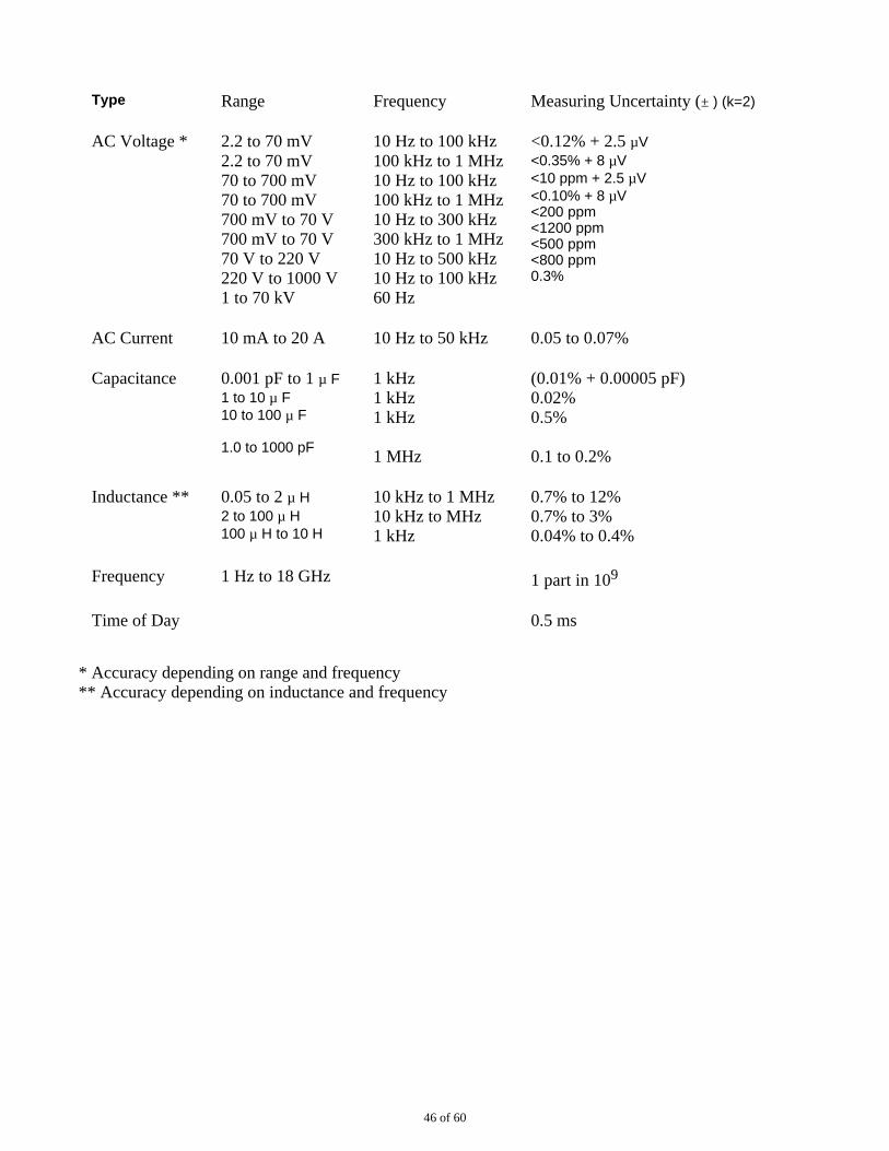
Type Range Frequency Measuring Uncertainty (± ) (k=2)
AC Voltage * 2.2 to 70 mV 2.2 to 70 mV 70 to 700 mV 70 to 700 mV 700 mV to 70 V 700 mV to 70 V 70 V to 220 V 220 V to 1000 V 1 to 70 kV
10 Hz to 100 kHz 100 kHz to 1 MHz 10 Hz to 100 kHz 100 kHz to 1 MHz 10 Hz to 300 kHz 300 kHz to 1 MHz 10 Hz to 500 kHz 10 Hz to 100 kHz 60 Hz
<0.12% + 2.5 µV <0.35% + 8 µV <10 ppm + 2.5 µV <0.10% + 8 µV <200 ppm <1200 ppm <500 ppm <800 ppm 0.3%
AC Current 10 mA to 20 A 10 Hz to 50 kHz 0.05 to 0.07%
Capacitance 0.001 pF to 1 µ F 1 to 10 µ F 10 to 100 µ F
1.0 to 1000 pF
1 kHz 1 kHz 1 kHz
1 MHz
(0.01% + 0.00005 pF) 0.02% 0.5%
0.1 to 0.2%
Inductance ** 0.05 to 2 µ H 2 to 100 µ H 100 µ H to 10 H
10 kHz to 1 MHz 10 kHz to MHz 1 kHz
0.7% to 12% 0.7% to 3% 0.04% to 0.4%
Frequency 1 Hz to 18 GHz 1 part in 109
Time of Day 0.5 ms
* Accuracy depending on range and frequency ** Accuracy depending on inductance and frequency
46 of 60
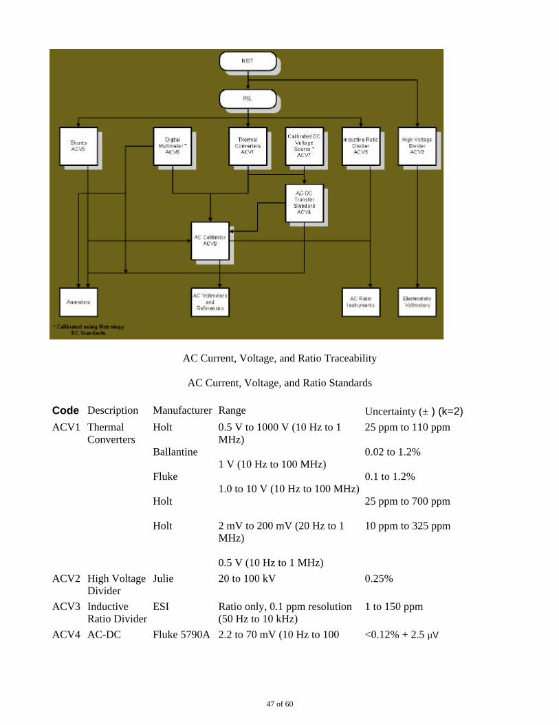
AC Current, Voltage, and Ratio Traceability
AC Current, Voltage, and Ratio Standards
Code Description Manufacturer Range Uncertainty (± ) (k=2)
ACV1 ThermalConverters
Holt
Ballantine
Fluke
Holt
Holt
0.5 V to 1000 V (10 Hz to 1MHz)
1 V (10 Hz to 100 MHz)
1.0 to 10 V (10 Hz to 100 MHz)
2 mV to 200 mV (20 Hz to 1MHz)
0.5 V (10 Hz to 1 MHz)
25 ppm to 110 ppm
0.02 to 1.2%
0.1 to 1.2%
25 ppm to 700 ppm
10 ppm to 325 ppm
ACV2 High VoltageDivider
Julie 20 to 100 kV 0.25%
ACV3 Inductive Ratio Divider
ESI Ratio only, 0.1 ppm resolution (50 Hz to 10 kHz)
1 to 150 ppm
ACV4 AC-DC Fluke 5790A 2.2 to 70 mV (10 Hz to 100 <0.12% + 2.5 µV
47 of 60
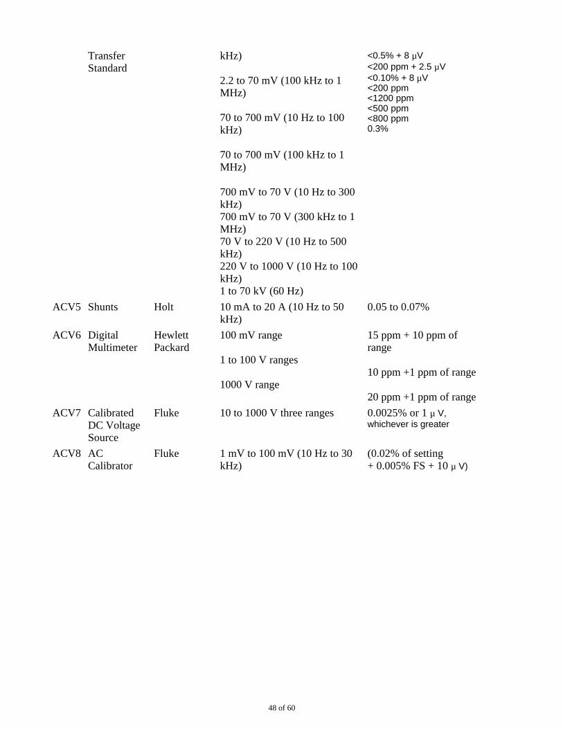
TransferStandard
kHz)
2.2 to 70 mV (100 kHz to 1MHz)
70 to 700 mV (10 Hz to 100kHz)
70 to 700 mV (100 kHz to 1MHz)
700 mV to 70 V (10 Hz to 300kHz) 700 mV to 70 V (300 kHz to 1MHz) 70 V to 220 V (10 Hz to 500kHz) 220 V to 1000 V (10 Hz to 100kHz) 1 to 70 kV (60 Hz)
<0.5% + 8 µV <200 ppm + 2.5 µV <0.10% + 8 µV <200 ppm <1200 ppm <500 ppm <800 ppm 0.3%
ACV5 Shunts Holt 10 mA to 20 A (10 Hz to 50kHz)
0.05 to 0.07%
ACV6 DigitalMultimeter
HewlettPackard
100 mV range
1 to 100 V ranges
1000 V range
15 ppm + 10 ppm ofrange
10 ppm +1 ppm of range
20 ppm +1 ppm of range
ACV7 Calibrated DC VoltageSource
Fluke 10 to 1000 V three ranges 0.0025% or 1 µ V,whichever is greater
ACV8 ACCalibrator
Fluke 1 mV to 100 mV (10 Hz to 30kHz)
(0.02% of setting + 0.005% FS + 10 µ V)
48 of 60
1 V to 100 V (10 Hz to 50 kHz)
1 mV to 100 mV (30 kHz to 100kHz)
1 V to 10 V (50 kHz to 100kHz)
1000 V range (50 Hz to 1 kHz)
1 mV to 100 mV (100 kHz to 1MHz)
1 V to 10 V (100 kHz to 1MHz)
100 V range (50 kHz to 100kHz)
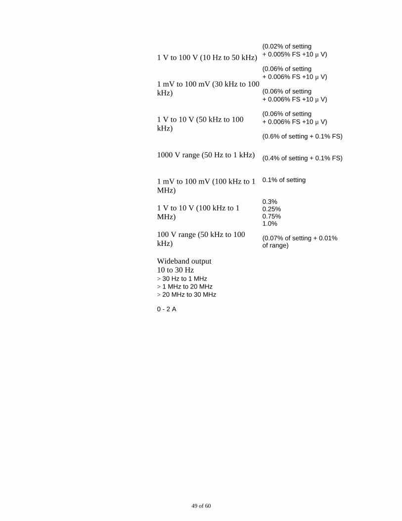
Wideband output 10 to 30 Hz > 30 Hz to 1 MHz > 1 MHz to 20 MHz > 20 MHz to 30 MHz
0 - 2 A
(0.02% of setting + 0.005% FS +10 µ V)
(0.06% of setting + 0.006% FS +10 µ V)
(0.06% of setting + 0.006% FS +10 µ V)
(0.06% of setting + 0.006% FS +10 µ V)
(0.6% of setting + 0.1% FS)
(0.4% of setting + 0.1% FS)
0.1% of setting
0.3% 0.25% 0.75% 1.0%
(0.07% of setting + 0.01%of range)
49 of 60
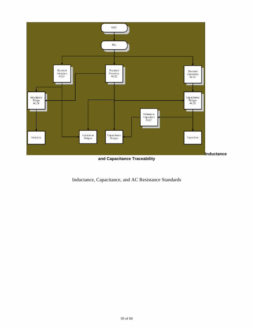
Inductanceand Capacitance Traceability
Inductance, Capacitance, and AC Resistance Standards
50 of 60
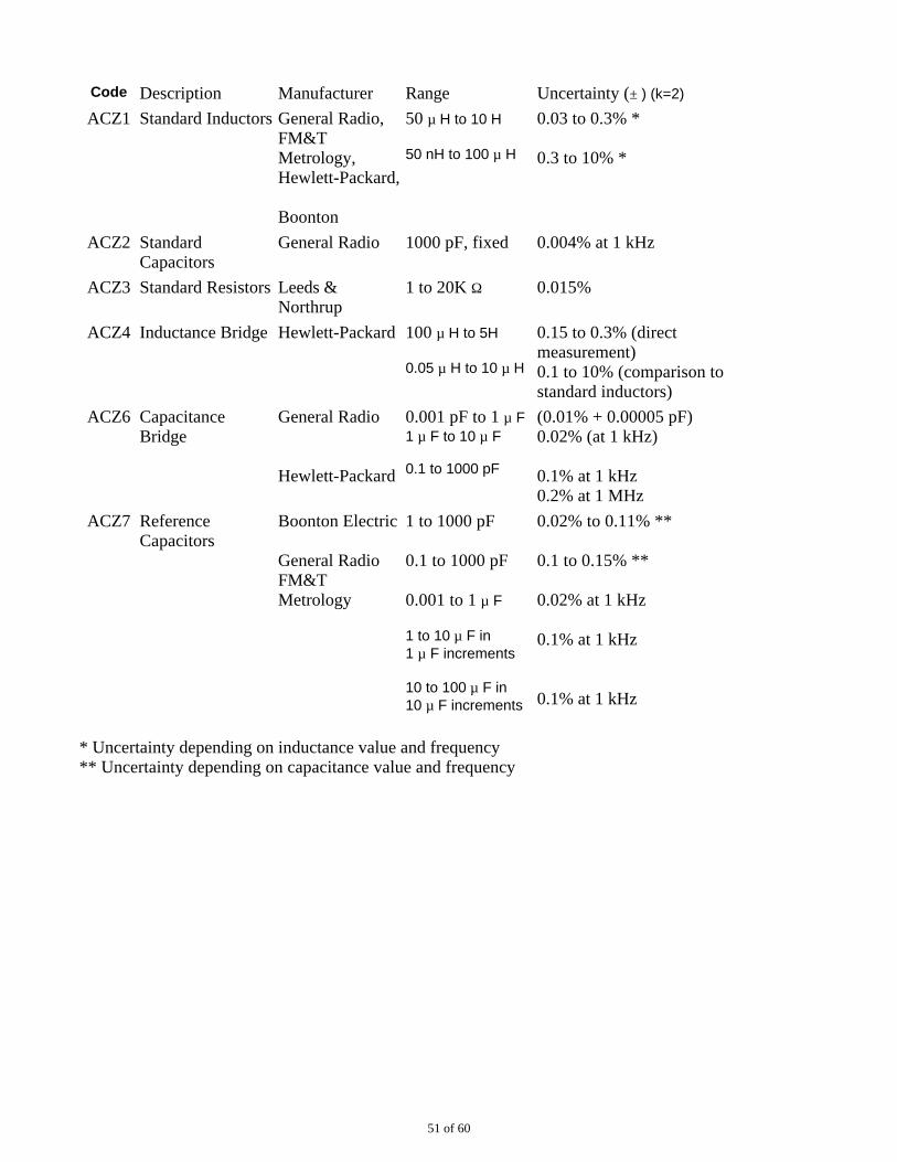
Code Description Manufacturer Range Uncertainty (± ) (k=2)
ACZ1 Standard Inductors General Radio, FM&TMetrology, Hewlett-Packard,
Boonton
50 µ H to 10 H
50 nH to 100 µ H
0.03 to 0.3% *
0.3 to 10% *
ACZ2 StandardCapacitors
General Radio 1000 pF, fixed 0.004% at 1 kHz
ACZ3 Standard Resistors Leeds &Northrup
1 to 20K Ω 0.015%
ACZ4 Inductance Bridge Hewlett-Packard 100 µ H to 5H
0.05 µ H to 10 µ H
0.15 to 0.3% (directmeasurement) 0.1 to 10% (comparison tostandard inductors)
ACZ6 CapacitanceBridge
General Radio
Hewlett-Packard
0.001 pF to 1 µ F 1 µ F to 10 µ F
0.1 to 1000 pF
(0.01% + 0.00005 pF) 0.02% (at 1 kHz)
0.1% at 1 kHz 0.2% at 1 MHz
ACZ7 ReferenceCapacitors
Boonton Electric
General Radio FM&TMetrology
1 to 1000 pF
0.1 to 1000 pF
0.001 to 1 µ F
1 to 10 µ F in 1 µ F increments
10 to 100 µ F in 10 µ F increments
0.02% to 0.11% **
0.1 to 0.15% **
0.02% at 1 kHz
0.1% at 1 kHz
0.1% at 1 kHz
* Uncertainty depending on inductance value and frequency ** Uncertainty depending on capacitance value and frequency
51 of 60
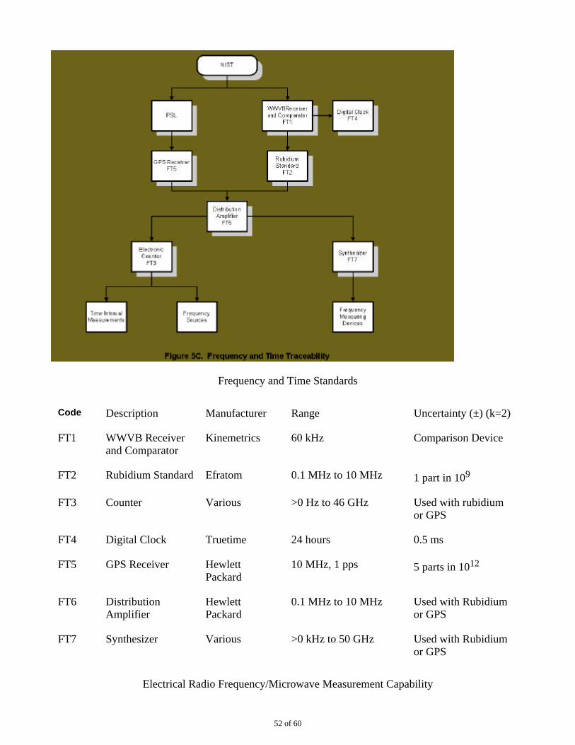
Frequency and Time Standards
Code Description Manufacturer Range Uncertainty (±) (k=2)
FT1 WWVB Receiverand Comparator
Kinemetrics 60 kHz Comparison Device
FT2 Rubidium Standard Efratom 0.1 MHz to 10 MHz 1 part in 109
FT3 Counter Various >0 Hz to 46 GHz Used with rubidiumor GPS
FT4 Digital Clock Truetime 24 hours 0.5 ms
FT5 GPS Receiver HewlettPackard
10 MHz, 1 pps 5 parts in 1012
FT6 DistributionAmplifier
HewlettPackard
0.1 MHz to 10 MHz Used with Rubidiumor GPS
FT7 Synthesizer Various >0 kHz to 50 GHz Used with Rubidiumor GPS
Electrical Radio Frequency/Microwave Measurement Capability
52 of 60
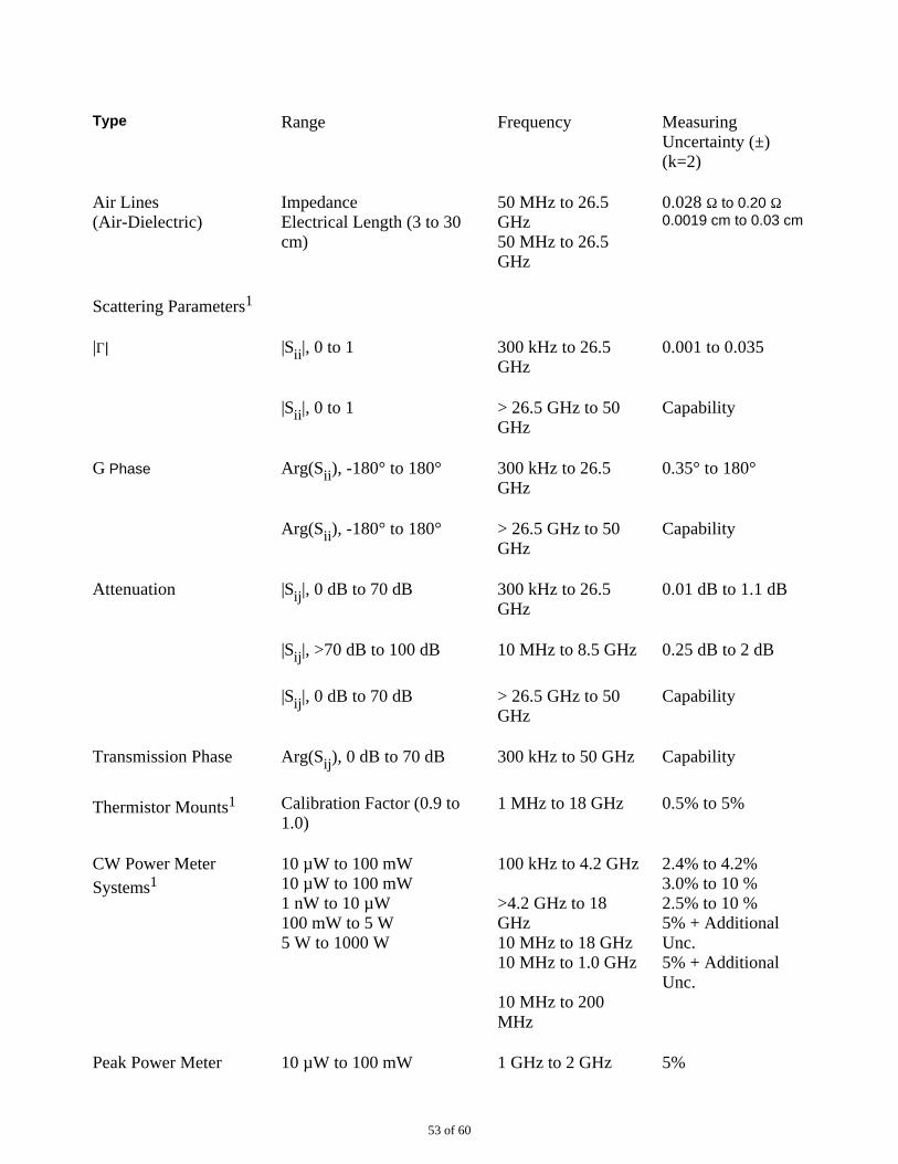
Type Range Frequency MeasuringUncertainty (±)(k=2)
Air Lines(Air-Dielectric)
Impedance Electrical Length (3 to 30cm)
50 MHz to 26.5GHz 50 MHz to 26.5GHz
0.028 Ω to 0.20 Ω 0.0019 cm to 0.03 cm
Scattering Parameters1
|Γ| |Sii|, 0 to 1 300 kHz to 26.5GHz
0.001 to 0.035
|Sii|, 0 to 1 > 26.5 GHz to 50GHz
Capability
G Phase Arg(Sii), -180° to 180° 300 kHz to 26.5GHz
0.35° to 180°
Arg(Sii), -180° to 180° > 26.5 GHz to 50GHz
Capability
Attenuation |Sij|, 0 dB to 70 dB 300 kHz to 26.5GHz
0.01 dB to 1.1 dB
|Sij|, >70 dB to 100 dB 10 MHz to 8.5 GHz 0.25 dB to 2 dB
|Sij|, 0 dB to 70 dB > 26.5 GHz to 50GHz
Capability
Transmission Phase Arg(Sij), 0 dB to 70 dB 300 kHz to 50 GHz Capability
Thermistor Mounts1 Calibration Factor (0.9 to1.0)
1 MHz to 18 GHz 0.5% to 5%
CW Power MeterSystems1
10 µW to 100 mW 10 µW to 100 mW 1 nW to 10 µW 100 mW to 5 W 5 W to 1000 W
100 kHz to 4.2 GHz
>4.2 GHz to 18GHz 10 MHz to 18 GHz 10 MHz to 1.0 GHz
10 MHz to 200MHz
2.4% to 4.2% 3.0% to 10 % 2.5% to 10 % 5% + AdditionalUnc. 5% + AdditionalUnc.
Peak Power Meter 10 µW to 100 mW 1 GHz to 2 GHz 5%
53 of 60
Systems1
Group Delay1 1 ns to 1200 ns 50 MHz to 2.0 GHz 0.005 ns to 0.5 ns
Noise Sources1 ENR ~ 15 dB 60 MHz to 3.55GHz
0.1 dB to 0.35
Chip Devices/WaferComponents
Various Measurements dc to 50 GHz Capability
1Referenced to 50Ω + j0Ω.
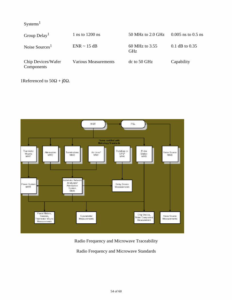
Radio Frequency and Microwave Traceability
Radio Frequency and Microwave Standards
54 of 60
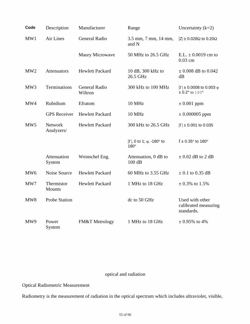
Code Description Manufacturer Range Uncertainty (k=2)
MW1 Air Lines General Radio 3.5 mm, 7 mm, 14 mm,and N
|Z| ± 0.028Ω to 0.20Ω
Maury Microwave 50 MHz to 26.5 GHz E.L. ± 0.0019 cm to0.03 cm
MW2 Attenuators Hewlett Packard 10 dB, 300 kHz to 26.5 GHz
± 0.008 dB to 0.042dB
MW3 Terminations General RadioWiltron
300 kHz to 100 MHz |Γ| ± 0.0008 to 0.003 φ ± 0.2° to 180°
MW4 Rubidium Efratom 10 MHz ± 0.001 ppm
GPS Receiver Hewlett Packard 10 MHz ± 0.000005 ppm
MW5 NetworkAnalyzers/
Hewlett Packard 300 kHz to 26.5 GHz |Γ| ± 0.001 to 0.035
|Γ|, 0 to 1; φ, -180° to180°
f ± 0.35° to 180°
AttenuationSystem
Weinschel Eng. Attenuation, 0 dB to 100 dB
± 0.02 dB to 2 dB
MW6 Noise Source Hewlett Packard 60 MHz to 3.55 GHz ± 0.1 to 0.35 dB
MW7 ThermistorMounts
Hewlett Packard 1 MHz to 18 GHz ± 0.3% to 1.5%
MW8 Probe Station dc to 50 GHz Used with othercalibrated measuringstandards.
MW9 PowerSystem
FM&T Metrology 1 MHz to 18 GHz ± 0.95% to 4%
optical and radiation
Optical Radiometric Measurement
Radiometry is the measurement of radiation in the optical spectrum which includes ultraviolet, visible,
55 of 60
and infrared light. The main radiometric reference standards at FM&T are heat-flow calorimeters andwavelength standards which include Helium-Neon (HeNe) lasers and Mercury spectral lamps. The heatflow calorimeters are calibrated by the Primary Standards Laboratory. The HeNe laser wavelengthstandard is calibrated by NIST because of its low uncertainty. The mercury spectral lamps do not requirecalibration because of their physical characteristics. Measurements performed include noncoherentmeasurement in the ultraviolet and visible regions of the optical spectrum and coherent measurementswhich consist of HeNe, Nd:YAG, and CO2 lasers. Power levels of these measurements range from
fractions of a microwatt to levels in excess of 1000 watts over wavelengths of 365 nm to 10.6 µm. Mostof the radiometric calibration activity at FM&T is calibrating Nd:YAG and CO2 laser power
sensors and meters in CW mode.
Optical Photometric Measurement
Photometry is the measurement of visible light intensity and energy as it affects the human eye. The mainphotometric reference standards at FM&T are standard photometers, calibrated by NIST. Standardphotometers output current and are used with a digital picoammeter to measure illuminance in units offootcandles or lux. When used in conjunction with an optical bench, luminous intensity, in units ofcandela, can be measured.
Radiation Measurement
Radiation measurements are made using standards of alpha-particle emission rate from plutonium 239and lead-probe neutron detectors. Alpha sources and lead probes are calibrated by the PSL. Accuracy ofthese standards ranges from ±3% to ±10%.
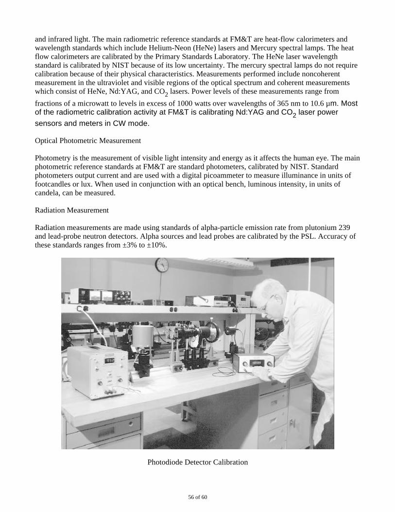
Photodiode Detector Calibration
56 of 60
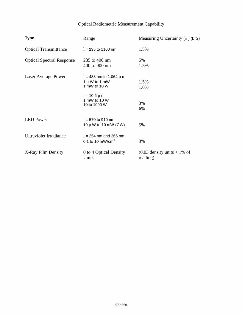
Optical Radiometric Measurement Capability
Type Range Measuring Uncertainty (± ) (k=2)
Optical Transmittance l = 235 to 1100 nm 1.5%
Optical Spectral Response 235 to 400 nm 400 to 900 nm
5% 1.5%
Laser Average Power l = 488 nm to 1.064 µ m 1 µ W to 1 mW 1 mW to 10 W
l = 10.6 µ m 1 mW to 10 W 10 to 1000 W
1.5% 1.0%
3% 6%
LED Power l = 570 to 910 nm 10 µ W to 10 mW (CW) 5%
Ultraviolet Irradiance l = 254 nm and 365 nm 0.1 to 10 mW/cm2 3%
X-Ray Film Density 0 to 4 Optical DensityUnits
(0.03 density units + 1% ofreading)
57 of 60
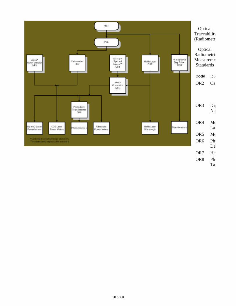
OpticalTraceability(Radiometric)
OpticalRadiometricMeasurementStandards
Code Description
OR2 Calorimeter
OR3 Digital Nanovoltmeter
OR4 Mercury SpectralLamp
OR5 Monochromator
OR6 Photodiode TrapDetector
OR7 HeNe Laser
OR8 Photographic StepTablet
58 of 60
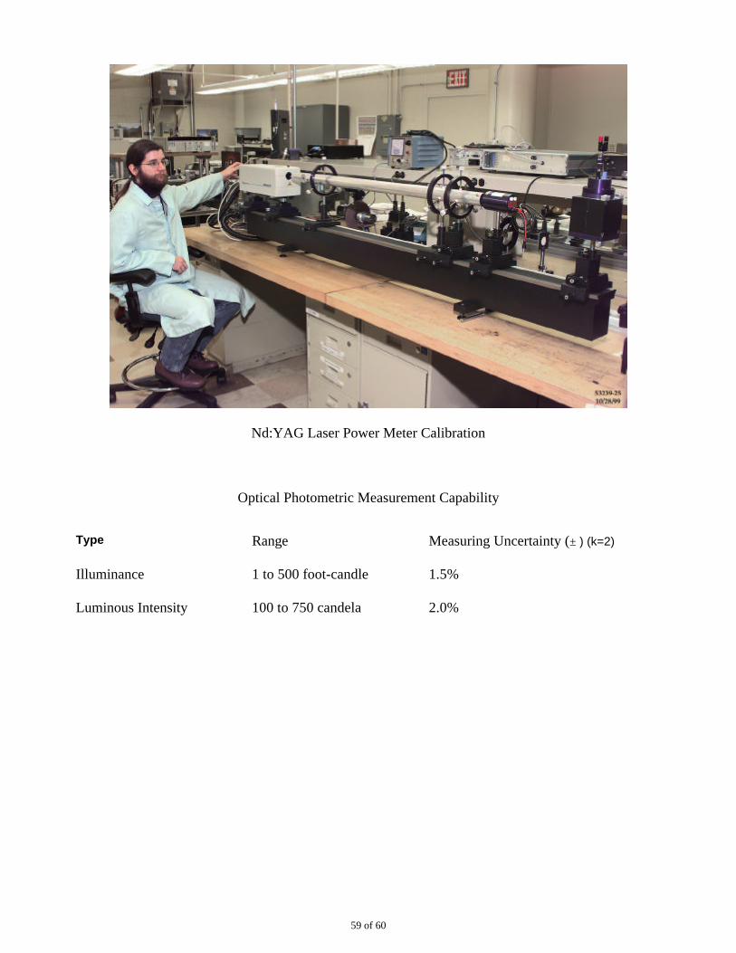
Nd:YAG Laser Power Meter Calibration
Optical Photometric Measurement Capability
Type Range Measuring Uncertainty (± ) (k=2)
Illuminance 1 to 500 foot-candle 1.5%
Luminous Intensity 100 to 750 candela 2.0%
59 of 60
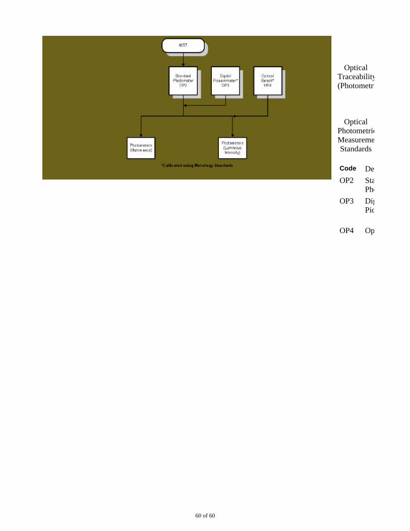
OpticalTraceability(Photometric)
OpticalPhotometricMeasurementStandards
Code Description
OP2 Standard Photometer
OP3 Digital Picoammeter
OP4 Optical Bench
60 of 60