mev proportional directional control valve series mev.. · 6 operation functioning of the...
TRANSCRIPT
Publ. MEV...A-E-06/07
FEATURES
* Load independent flow control corresponds to thespool-position proportional to the electrical inputsignal.
* The pump pressure always corresponds to the userpressure, +3,6,8 or 12 bar (43, 86, 114 or 172 psi)∆p compensator.
* The built-in pump-unloading valve results in:- very low power turned into heat;- minimum loading of the prime mover.
* User speed is precisely controlled under all loadconditions.
* Progressive regulating curve; no pressure peakswhen switching; sensitive control even foralternating pressures.
* Constant working speed of differential cylinders atthe different regulating flow to the valve by grindingangle.
* Constant recirculation pressure independent of thenumber of units.
* Any limiting of flow for every user port.
* Load independent switching adjustment, constantacceleration and deceleration.
* Proportional solenoids with longer life for thearmature in the oil (explosion proof solenoids “II 2 EExmII T4 or T5”, available).
* Proportional directional control valves alsoavailable as:- Manual proportional series MHV and- Hydraulic proportional series MOV.
Any combination of these control options ispossible.
* The sub plate system allows a construction up to8 control valves.
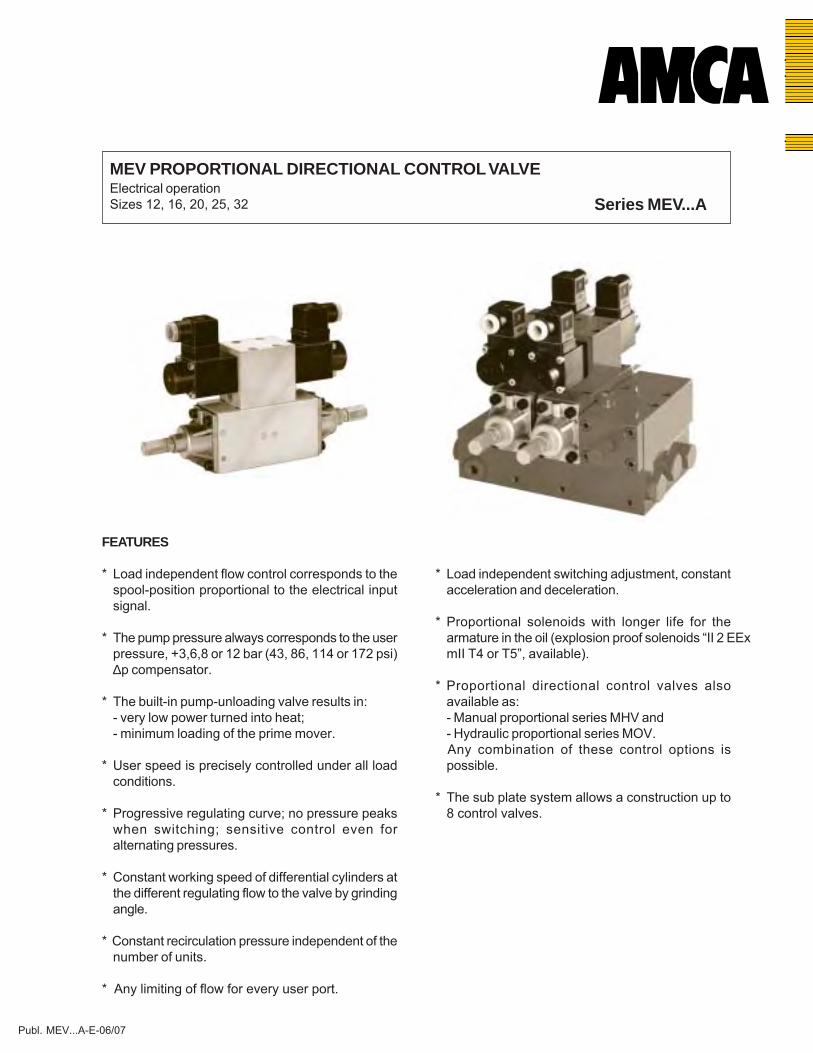
MEV PROPORTIONAL DIRECTIONAL CONTROL VALVEElectrical operationSizes 12, 16, 20, 25, 32 Series MEV...A
2
TECHNICAL DATA
Operating pressure (P,A,B) ...350 bar (5000 psi)Maximum return pressure (T): - aluminium springcaps 15 bar (214 psi) - cast iron springcaps 30 bar (428 psi)∆p compensator 3; 6; 8 or 12 bar (43; 86; 114 or 172 psi)Pressure setting range 5...350 bar (72...5000 psi)Flow range ...800 l/min (...211 USgpm) - with 32 cSt at 40oCFluid Mineral oil according to DIN 51524/51525Fluid temperature range -35...+80°C (-31°...+176°F)Viscosity range 2,8...380 cSt, optimal 30 cStContamination level max. according to NAS 1638 Class 9 or ISO 18/15Nominal voltage 12 V, 24 VNominal current 12 V DC = 1.400 mA ; 24 V DC = 700 mAHysteresis 3...8% (50...800 l/min (13...211 USgpm))Continuous operating 100%Type of protection IP 65, optional IP67/II 2 EEx m II T4Recommended dither frequency 100HzMounting position optional
Size working ports: MEV12 : 1/2" BSP (SAE optional)(in subplate) MEV16 : 3/4" BSP (SAE optional)
MEV20 : 1" BSP (SAE optional)MEV25 : 1 1/4" BSP (SAE optional)MEV32 : 1 1/2" BSP (SAE optional)
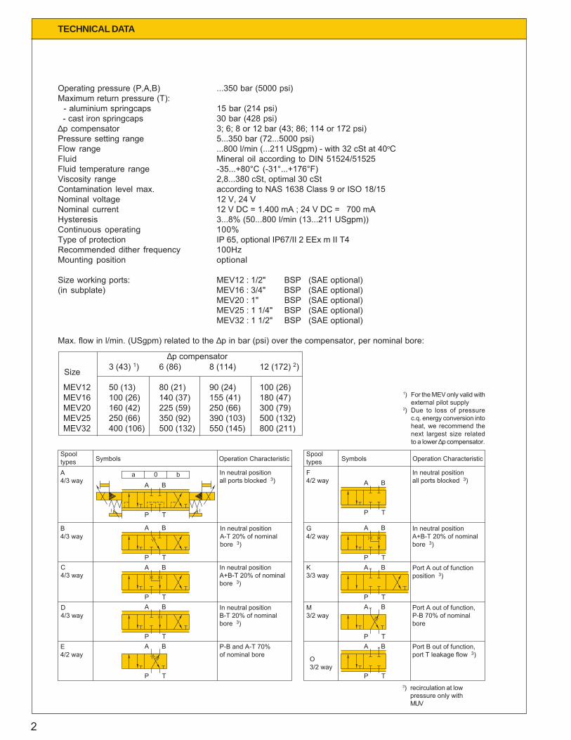
Max. flow in l/min. (USgpm) related to the ∆p in bar (psi) over the compensator, per nominal bore:
1) For the MEV only valid withexternal pilot supply
2) Due to loss of pressurec.q. energy conversion intoheat, we recommend thenext largest size relatedto a lower ∆p compensator.
3) recirculation at lowpressure only withMUV
3 (43) 1) 6 (86) 8 (114) 12 (172) 2) MEV12 50 (13) 80 (21) 90 (24) 100 (26) MEV16 100 (26) 140 (37) 155 (41) 180 (47) MEV20 160 (42) 225 (59) 250 (66) 300 (79) MEV25 250 (66) 350 (92) 390 (103) 500 (132) MEV32 400 (106) 500 (132) 550 (145) 800 (211)
Size
∆p compensator
X
XX
Spool types Symbols Operation Characteristic
Spool types Symbols Operation Characteristic
A4/3 way
a 0 bA B
P T
A B
P TA B
P TA B
P TA B
P T
A B
P T
A B
P TA B
P TA B
P TA B
P T
In neutral position all ports blocked 3)
B4/3 way
In neutral position A-T 20% of nominal bore 3)
C4/3 way
In neutral position B-T 20% of nominal bore 3)
D 4/3 way
In neutral position A+B-T 20% of nominal bore 3)
E4/2 way
P-B and A-T 70% of nominal bore
F4/2 way
In neutral position all ports blocked 3)
G4/2 way
In neutral position A+B-T 20% of nominal bore 3)
K3/3 way
Port A out of function position 3)
M3/2 way
Port A out of function, P-B 70% of nominal bore
O3/2 way
Port B out of function, port T leakage flow 3)
3
DESCRIPTION
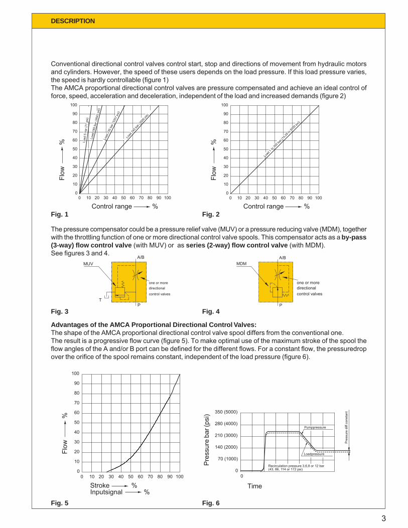
Conventional directional control valves control start, stop and directions of movement from hydraulic motorsand cylinders. However, the speed of these users depends on the load pressure. If this load pressure varies,the speed is hardly controllable (figure 1)The AMCA proportional directional control valves are pressure compensated and achieve an ideal control offorce, speed, acceleration and deceleration, independent of the load and increased demands (figure 2)
The pressure compensator could be a pressure relief valve (MUV) or a pressure reducing valve (MDM), togetherwith the throttling function of one or more directional control valve spools. This compensator acts as a by-pass(3-way) flow control valve (with MUV) or as series (2-way) flow control valve (with MDM).See figures 3 and 4.
100
90
80
70
60
50
40
30
20
10
1000
20 4030 50 7060 80 10090
Load
235
bar
(335
7 ps
i)
Load
185
bar
(264
3 ps
i)
Load
5 b
ar (7
1 ps
i)
Load
245 b
ar (35
00 ps
i)
Load
1 to
350 b
ar (14
,29 to
5000
psi)
0
20
10
40
30
50
60
70
80
90
100
0 10 3020 40 8050 60 70 90 100
Advantages of the AMCA Proportional Directional Control Valves:The shape of the AMCA proportional directional control valve spool differs from the conventional one.The result is a progressive flow curve (figure 5). To make optimal use of the maximum stroke of the spool theflow angles of the A and/or B port can be defined for the different flows. For a constant flow, the pressuredropover the orifice of the spool remains constant, independent of the load pressure (figure 6).
MUV
Tcontrol valvesdirectionalone or more
A/B
P
one or moredirectionalcontrol valves
P
A/BMDM
Pre
ssur
e di
ff.co
nsta
nt350 (5000)
280 (4000)
210 (3000)
140 (2000)
(43, 86, 114 or 172 psi)Recirculation pressure 3,6,8 or 12 bar
70 (1000)
00
Loadpressure
Pumppressure
100 20 4030 50 7060 80 90 1000
10
20
30
40
50
60
70
80
100
90
Stroke %Inputsignal %
Flow
%
Time
Pres
sure
bar
(psi
)Fig. 1
Control range %
Flow
%
Control range %Fl
ow
%Fig. 2
Fig. 3 Fig. 4
Fig. 5 Fig. 6
4
Functioning of the by-pass (3-way) flow controlvalve (with MUV)
(this type is used in combination with fixeddisplacement pumps) (fig. 7 and 8)
The AMCA-MUV has three functions:
1. Energy savingIf the directional control spools are in neutral position(spool 1 in fig.7), and the pump is running, thepressure relief valve 1 (MUV) opens at low pressure(depending on the spring 3, 6, 8 or 12 bar (43, 86,114 or 172 psi)).P and T are connected. The power (pxqv) turned intoheat is very low.The spring chamber is connected, via the “load-pressure check back system”, to T (tank).(example fig. 21)
2. Load independent flow control(acting as a 3-way flow control valve)If one directional control spool is actuated (spool 2in fig. 7, where P is connected to B2), the load-pressure is connected to the spring chamber of theMUV. The left part of the “load pressure check backsystem” is closed by spool 2. The load-pressureadded to the spring-equivalent pressure is in balancewith the pressure at P. Therefore the ∆p over thedirectional control valve remains constant (3, 6, 8 or12 bar (43, 86, 114 or 172 psi)).As qv = k. ∆p, the flow remains constant, at a givenopening of port B2, independent of the load-pressure.The output (flow) is proportional to the input signal(displacement of spool).The unnecessary pumpflow returns to tank.
3. Adjustable maximum load pressureThe maximum load-pressure can be restricted by theadjustable relief valve 2.
Functioning of the series (2-way) flow controlvalve (with MDM)
(this type is used in combination with variabledisplacement/pressure compensated pumps(example fig. 9 and 10) or accumulator circuits.
The AMCA-MDM has three functions:
1. Energy savingIf the directional control spools are in neutral position(spool 1 in fig. 9) and the pump is running, thepressure reducing valve MDM (normally open) tends
OPERATION
to close (is balancing).The pressure controls the pump-capacity to aminimum. Again the power (p x qv) turned into heatis very low.The spring chamber is connected, via the “load-pressure check back system” to T (tank).
2. Load independent flow control(acting as a 2-way flow control valve)If one directional control spool is actuated (spool 2in fig. 9) MDM-orifice throttles the flow and reducesthe pressure. This reduced pressure is connected toB2.The left part of the “load pressure check back system”is closed by spool 2. The load pressure added to thespring-equivalent pressure (3, 6, 8 or 12 bar (43, 86,114 or 172 psi)) is in balance with the reducedpressure.Therefore the ∆p at flow angle 2 remains constant(3, 6, 8 or 12 bar (42, 86, 114 or 172 psi)). As qv =k. ∆p, the flow remains constant at a given openingof port B2, independent of the load pressure.The output (flow) is proportional to the input signal(displacement of spool).There is no unnecessary pumpflow (pump capacityis controlled by pressure).
3. Adjustable maximum load pressureThe maximum load pressure can be restricted bythe adjustable relief valve 2.
Functioning of the by-pass (3-way) flow controlvalve (with MUV/R)
(this type is used if there is a need to use the MUVas a sequence valve)(fig. 11 and 12)The function is the same as described in clause 1(fig. 7). The return bore is blocked (as in fig. 9). Thereis an additional possibility of directing the pumpflowfrom P to R (fig. 12) to feed another circuit up to 350bar, or to control the adjusting mechanism on avariable displacement pump (fig. 11).(example fig. 24)
Note: (1) If the systempump is of the load sensing type,no compensator is required. (example fig.25)
(2) For simultanious operation of the proportionaldirectional control valve, independent ofloadpressure, we advice a pressurecompensator for each control valve.For flows < 201 l/min. (53 USgpm) per controlsection, the MFC stacked valves are a goodalternative in this case. (see Publ. F12/18K)

5
OPERATION
another circuit
Spool 2
B2
End plate
A2
MD
M o
rific
e
Pressure relief valve 1 (MUV)
Pressure relief valve 1 (MUV/R)
0
Reducing valve (MDM)
0
M
Inlet plate
Spring chamber
B1
T
P
A1
spool orifice
T1
End plate
Load-pressure check back system
Adjustable relief valve 2Spool 1 Damping-screw
B1B2
A1A2
spool orifice
R
P
M
Spring chamber
Inlet plate
Damping-screwLoad-pressure check back system
Spool 1Spool 2Adjustable relief valve 2
Adjustable relief valve 2
Load-pressure check back system
T1
B2 B1
End plate
A2 A1
P
Spring chamber
Inlet plate
Spool 1Spool 2 Damping-screw
P
A1 B1
P
T
T
A1 B1
A2 B2
A2 B2
A1
R TP
B1 A2 B2
Fig. 9 Series flow control valve Fig. 10 With MDM
Fig.7 By-pass control valve Fig. 8 With MUV
Fig. 11 By-pass flow control valve Fig. 12 With MUV/R

6
OPERATION
Functioning of the proportional directional control valve with electrically controlled pilot stage. (MEV)
(Fig. 13, 14 and 15)
When solenoid a is actuated it pushes the pilot spool towards solenoid b and opens throttle position 1.This allows pilot pressure to the springchamber 1 (speed controlled by the adjustable restriction 5) and alsothrough bore 3 to the end of the pilot spool opposite to solenoid a.The balance force on the pilot spool is the force of the solenoid which is proportional to the electric input.The balance force equates the pilot pressure in solenoid b and also in springchamber 1.This pressure pushes the main spool against the spring in springchamber 2 and thus takes up a positionproportional to the electric input signal.
With the screws on the springchambers the maximum flow can be adjust by turning in the screw and block themain spool in his stroke.
Solenoid b
Springchamber 1
Throttle position 1
3
T A TP BSpringchamber 2
Throttle position 2
5 6
Solenoid a
4
b
P
A B
T
a
a
P
A
T
B
b
Fig. 13 MEV
Fig. 14 (detailed) Fig. 15 (simplified)
7
24V
12V
0
0
300 400
600 800
600
1200
500
1000
650
1300
8 bar (114 psi)
3 bar (43 psi)
6 bar (86 psi)
12 bar (172 psi)100
90
80
70
60
50
40
30
20
10
050200 10 30 40 8060 70 90 100
min.
max.100
90
80
70
60
50
40
30
20
10
050200 10 30 40 8060 70 90 100
0
012V
24V 300
600 1200
600400
800
500
1000
650
1300
3000
16
12
25
20
32
15010050 250200 350 400
DIAGRAMS
Stroke %
Flow
%
Inputsignal mA.
Stroke %
Flow
%
Inputsignal mA.
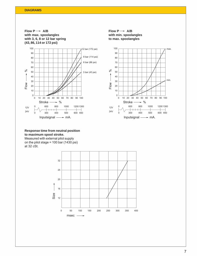
Response time from neutral positionto maximum spool stroke.Measured with external pilot supplyon the pilot stage = 100 bar (1430 psi)at 32 cSt.
msec
Siz
e
Flow P A/Bwith max. spoolangleswith 3, 6, 8 or 12 bar spring(43, 86, 114 or 172 psi)
Flow P A/Bwith min. spoolanglesto max. spoolangles

8
DIAGRAMS
0
0
50 100 150 200
3 (43)
6 (86)
9 (129)
12 (172)
3 bar (43 psi)
6 bar (86 psi)
8 bar (114 psi)
12 bar (172 psi)
MUV-12
(13.2) (26.4) (39.6) (52.8)
MUV-1612 bar (172 psi)
8 bar (114 psi)
6 bar (86 psi)
3 bar (43 psi)
9 (129)
3 (43)
0
6 (86)
12 (172)
(26.4)0
(13.2)50 100
(39.6)150
(52.8)200
400300
MUV-20
(79.2) (105.6)
12 bar (172 psi)
8 bar (114 psi)
6 bar (86 psi)
3 bar (43 psi)
9 (129)
3 (43)
0
6 (86)
12 (172)
0(26.4)100
(52.8)200 400 600
MUV-25
(52.8)200
(105.6) (158.5)
12 bar (172 psi)
8 bar (114 psi)
6 bar (86 psi)
3 bar (43 psi)
9 (129)
6 (86)
3 (43)
0
12 (172)
0
3 bar (43 psi)
6 bar (86 psi)
12 bar (172 psi)
8 bar (114 psi)
800
15 (214)
18 (257)
21 (300)
24 (343)
MUV-32
(211.4)
3 (43)
6 (86)
9 (129)
12 (172)
0
0(52.8)
200(105.6)
400(158.5)
600
Flow l/min. (USgpm)
∆p
bar
(psi
)
Flow l/min. (USgpm)∆p
b
ar (p
si)
Flow l/min. (USgpm)
∆p
bar
(psi
)
Flow l/min. (USgpm)
∆p
bar
(psi
)
Flow l/min. (USgpm)
∆p
bar
(psi
)
Free recirculation pressure P TMUV with 3, 6, 8 or 12 bar spring (43, 86, 114 or 172 psi).

9
0
0
50 80 100
10 (143)
15 (214)
20 (286)
A1-T
A6-T
B6-T
B1-T5 (72)
MEV-12
(13.2) (21.1) (26.4)
Flow l/min. (USgpm)
∆p
bar
(psi
)
0 160 300225
B1-T
B6-T
A6-T
A1-TMEV-20
(42.3) (59.4) (79.3)
5 (72)
10 (143)
0
15 (214)
20 (286)
250 500
B1-T
B6-T
MEV-25
A6-T
A1-T
(66.1) (132.1)
10 (143)
5 (72)
0
20 (286)
15 (214)
0(92.5)
350
400 800
B1-T
B6-T
A6-T
A1-T
MEV-32
(105.7) (211.4)
10 (143)
5 (72)
0
20 (286)
15 (214)
0(132.1)
500
A1 A2 A4A3 A5 A6
T B1 B2 B4B3 B5 B6
Flow l/min. (USgpm)
∆p
bar
(psi
)MEV-16
B6-T
B1-T
A6-T
A1-T
0
5 (72)
10 (143)
15 (214)
20 (286)
0(26.4)
100 140(37)
180(47.6)
Flow l/min. (USgpm)
Flow l/min. (USgpm)
∆p
bar
(psi
)
Pressure drop A/B T
DIAGRAMS
Flow l/min. (USgpm)
∆p
bar
(psi
)
measured with C-spool andmax. spoolopening A/B TViscosity 32 cSt.Including subplates and couplings.
∆p
bar
(psi
)
10
APA..DM
P
MDM..A
A
A..EV
T2
MEV..A
b
B
a
aBA
P T
b
A..UV
T P
MUV..A
A..EV
A B
AP
A
P
MEV..A
b
a
a
T
Bb
3
1
2
CONFIGURATION
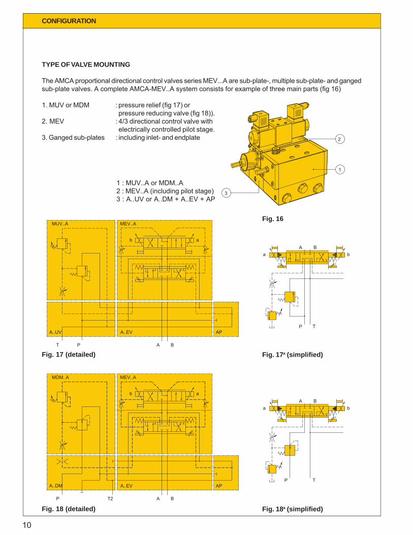
TYPE OF VALVE MOUNTING
The AMCA proportional directional control valves series MEV...A are sub-plate-, multiple sub-plate- and gangedsub-plate valves. A complete AMCA-MEV..A system consists for example of three main parts (fig 16)
1. MUV or MDM : pressure relief (fig 17) orpressure reducing valve (fig 18)).
2. MEV : 4/3 directional control valve withelectrically controlled pilot stage.
3. Ganged sub-plates : including inlet- and endplate
Fig. 17 (detailed) Fig. 17a (simplified)
Fig. 18 (detailed) Fig. 18a (simplified)
Fig. 16
1 : MUV..A or MDM..A2 : MEV..A (including pilot stage)3 : A..UV or A..DM + A..EV + AP
11
OPTIONS
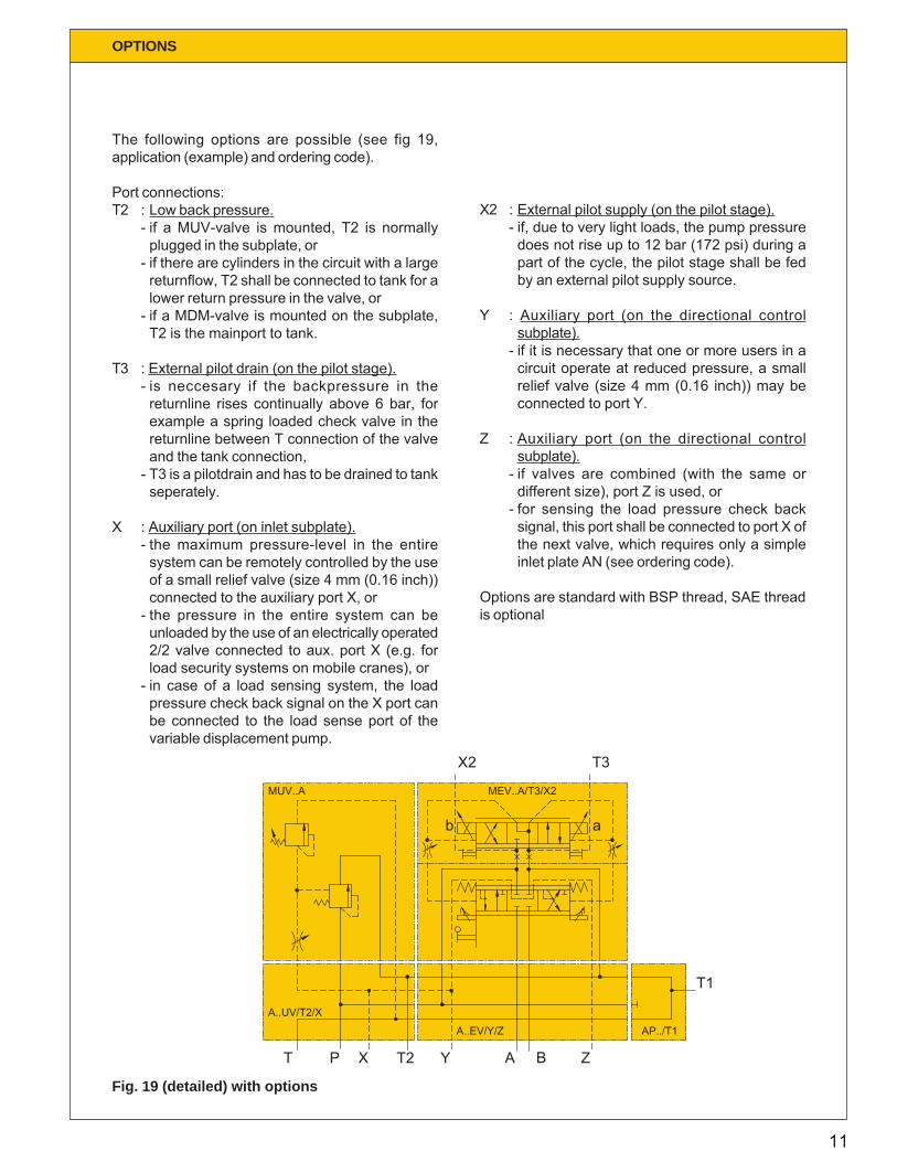
The following options are possible (see fig 19,application (example) and ordering code).
Port connections:T2 : Low back pressure.
- if a MUV-valve is mounted, T2 is normallyplugged in the subplate, or
- if there are cylinders in the circuit with a largereturnflow, T2 shall be connected to tank for alower return pressure in the valve, or
- if a MDM-valve is mounted on the subplate,T2 is the mainport to tank.
T3 : External pilot drain (on the pilot stage).- is neccesary if the backpressure in the
returnline rises continually above 6 bar, forexample a spring loaded check valve in thereturnline between T connection of the valveand the tank connection,
- T3 is a pilotdrain and has to be drained to tankseperately.
X : Auxiliary port (on inlet subplate).- the maximum pressure-level in the entire
system can be remotely controlled by the useof a small relief valve (size 4 mm (0.16 inch))connected to the auxiliary port X, or
- the pressure in the entire system can beunloaded by the use of an electrically operated2/2 valve connected to aux. port X (e.g. forload security systems on mobile cranes), or
- in case of a load sensing system, the loadpressure check back signal on the X port canbe connected to the load sense port of thevariable displacement pump.
X2 : External pilot supply (on the pilot stage).- if, due to very light loads, the pump pressure
does not rise up to 12 bar (172 psi) during apart of the cycle, the pilot stage shall be fedby an external pilot supply source.
Y : Auxiliary port (on the directional controlsubplate).
- if it is necessary that one or more users in acircuit operate at reduced pressure, a smallrelief valve (size 4 mm (0.16 inch)) may beconnected to port Y.
Z : Auxiliary port (on the directional controlsubplate).
- if valves are combined (with the same ordifferent size), port Z is used, or
- for sensing the load pressure check backsignal, this port shall be connected to port X ofthe next valve, which requires only a simpleinlet plate AN (see ordering code).
Options are standard with BSP thread, SAE threadis optional
A..UV/T2/X
T P X T2
MUV..A
T1
A..EV/Y/Z
Y A B Z
AP../T1
MEV..A/T3/X2
b
X2
a
T3
Fig. 19 (detailed) with options
12
VARIANTS/OPTIONS
The following variants/options are possible (seeordering code, page 26 and 28).
Compensator (MUV/MDM) variants:Recirculation pressure:
V : Adjustment 6...12 bar (86...172 psi). Thespring in the spring chamber is adjustablebetween 6 and 12 bar (86 and 172 psi) forexact control of the max. flow on users Aand B of the proportional directional controlvalve. (see page 26)
Max. pressure adjustments variants:H : With handwheel (Ø 30mm, Ø 1.18inch) for
manual adjustment without using toolsE2 : Electrical remote control up to 350 bar (5000
psi)W : Without pressure adjustment, no relief valve.
Options:Q : Normally, MUV spools have no connection
between the P bore and the spring chamber.In certain cases, a small orifice (0,6 mm) toprovide a “positive feed in” is desirable. Asan example: for multi-section blocks.
P : Normally, MDM spools are mounted with asmall orifice, to connect the reduced pressureto the spring chamber for quick response. Ifone or more MDM valves are connected to aload sensing pump, option P (plugged MDM-spool) is recommended.
Electrical control system:N : No proportional control, on/offF : Proportional control
Spool types:A,B,C,D,E,F,G,K,M,O : See page 2
Flow:.../... : Flow port A/port B in litres/minute, the choice
has to be made in combination with the ∆p ofthe compensator (MUV or MDM). For themaximum flow per ∆p compensator see page2.Note: the control valve is standard equipedwith stroke limitation screws in the springcaps, if the flow of a port is adjusted with thisscrew, the electrical input signal has a shorterbandwidth.
Options:ACS : Adjustable Centering Springs on the main
spool, if the users A and B should haveexactly the same flow in combination with thesame current on solenoids a and b.
G : Cast iron spring caps. If the standardaluminium caps are not suitable for theenvironment conditions. (for instance sea-water resistance)
JS : Additional connection for hydraulical control,with shuttle valves and restriction for externalpilot control e.g., through pilot pressuredevices.
M : Additional manual control, a second controlpossibility in addition to the electrical control.(manual override)
MSW : As option M, suitable for special environmentconditions like seawater. (the springcap is alsoin cast iron)
N : Neutral spool position signal, through inductiveswitch.
Solenoid types:A : 12 VDC IP65 with emergency control by pinB : 24 VDC IP65 with emergency control by pin
(standard)E : 12 VDC IP65 with emergency control by
buttonF : 24 VDC IP65 with emergency control by
buttonH : 24 VDC IP67 with explosion proof, II 2 G EEx
m II T4, IP 57, including connector and 5 metres(16.4 ft) cable
J : 24 VDC Military, IP 67, without femaleconnector
Control valve (MEV) variants:
13
APPLICATIONS
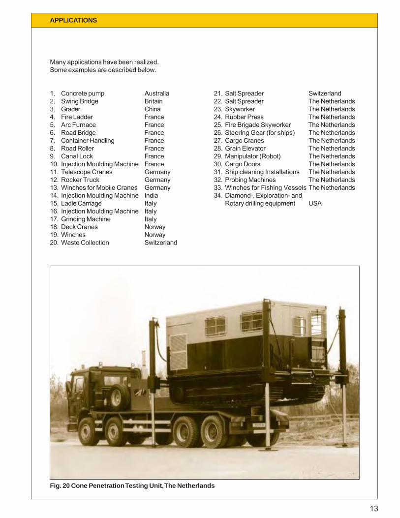
Many applications have been realized.Some examples are described below.
1. Concrete pump Australia2. Swing Bridge Britain3. Grader China4. Fire Ladder France5. Arc Furnace France6. Road Bridge France7. Container Handling France8. Road Roller France9. Canal Lock France10. Injection Moulding Machine France11. Telescope Cranes Germany12. Rocker Truck Germany13. Winches for Mobile Cranes Germany14. Injection Moulding Machine India15. Ladle Carriage Italy16. Injection Moulding Machine Italy17. Grinding Machine Italy18. Deck Cranes Norway19. Winches Norway20. Waste Collection Switzerland
21. Salt Spreader Switzerland22. Salt Spreader The Netherlands23. Skyworker The Netherlands24. Rubber Press The Netherlands25. Fire Brigade Skyworker The Netherlands26. Steering Gear (for ships) The Netherlands27. Cargo Cranes The Netherlands28. Grain Elevator The Netherlands29. Manipulator (Robot) The Netherlands30. Cargo Doors The Netherlands31. Ship cleaning Installations The Netherlands32. Probing Machines The Netherlands33. Winches for Fishing Vessels The Netherlands34. Diamond-, Exploration- and
Rotary drilling equipment USA
Fig. 20 Cone Penetration Testing Unit, The Netherlands
14
APPLICATIONS
48l/min.
M
7l/min.
M
4 bar
120 bar60 bar
MUV..A
A..UV
MEV-12-ASFFC-50
T P
A..EV
A B
b
MEV..A
AP
a
AP-12-AA-12-EV
A-12-UVMUV-12-AS6S
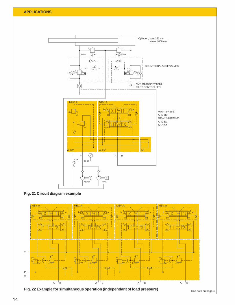
COUNTERBALANCE VALVES
PILOT CONTROLLEDNON-RETURN VALVES
stroke 1800 mmCylinder , bore 250 mm
A
XLP
B
T
b
MEV..A
a b
MEV..A
A B A B A B
a b
MEV..A
a b
MEV..A
a
Fig. 21 Circuit diagram example
Fig. 22 Example for simultaneous operation (independant of load pressure) See note on page 4.
15
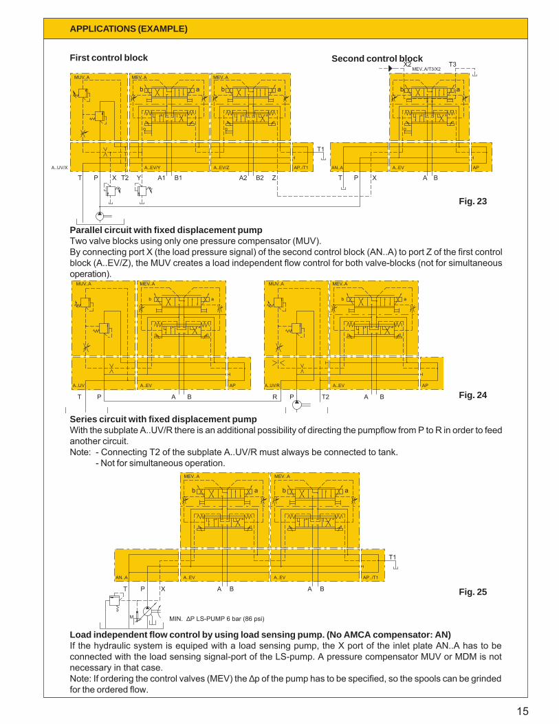
Parallel circuit with fixed displacement pumpTwo valve blocks using only one pressure compensator (MUV).By connecting port X (the load pressure signal) of the second control block (AN..A) to port Z of the first controlblock (A..EV/Z), the MUV creates a load independent flow control for both valve-blocks (not for simultaneousoperation).
Series circuit with fixed displacement pumpWith the subplate A..UV/R there is an additional possibility of directing the pumpflow from P to R in order to feedanother circuit.Note: - Connecting T2 of the subplate A..UV/R must always be connected to tank.
- Not for simultaneous operation.
APPLICATIONS (EXAMPLE)
B2
A..EV/YA..UV/X
T P X T2 Y
MUV..A
b
MEV..A
A1 B1
A..EV/Z
A2
a b
MEV..A
T3MEV..A/T3/X2
Z
AP../T1
T1
T
AN..A
a
A..EV
P X A B
b
X2
AP
a
A..UV
T P
A..EV
A B
AP
b
MUV..A MEV..A
a
A..UV/R
R P T2
A..EV
A B
AP
MUV..A
ab
MEV..A
AP../T1
T1
A
A..EV
B
b a
MEV..A
a
A..EV
A B
MEV..A
b
T P
AN..A
X
M MIN. ∆P LS-PUMP 6 bar (86 psi)
Load independent flow control by using load sensing pump. (No AMCA compensator: AN)If the hydraulic system is equiped with a load sensing pump, the X port of the inlet plate AN..A has to beconnected with the load sensing signal-port of the LS-pump. A pressure compensator MUV or MDM is notnecessary in that case.Note: If ordering the control valves (MEV) the ∆p of the pump has to be specified, so the spools can be grindedfor the ordered flow.
Fig. 23
Fig. 24
Fig. 25
First control block Second control block
16
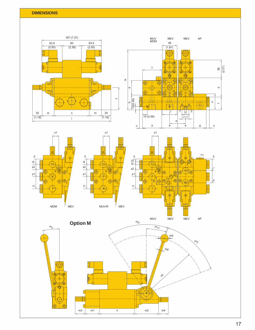
DIMENSIONS
Nominal bore
X2,T3T1
XA,B,P,T,T2
Y,Z
12 16 20 25 32
1/2" (8)
1/8" (4)
3/8" (6)1/8" (4)
1/8" (4)1/4" (6)
3/8" (6)1/8" (4)
1/8" (4)3/4" (12)
1/4" (6)1/8" (4)1/2" (8)
1" (16)1/4" (6)
3/4" (12)
1/4" (6)
1/8" (4)1/4" (6)
1 1/4" (20)
1" (16)
1 1/2" (24)
1/4" (6)1/8" (4)
1/4" (6)
f
a
de
bc
kl
j
gh
w
x2y1
x1
t2
v
st1
p1r
mn
y2z
u
60 (2.36)
40 (1.58)50 (1.97)46 (1.81)
46 (1.81)60 (2.36)
60 (2.36)246 (9.69)
40 (1.58)50 (1.97)46 (1.81)
188 (7.41)20 (0.79)
11 (0.43)33 (1.30)
74 (2.92)
M6x8
17 (0.67)93 (3.66)
38 (1.50)110 (4.33)
36 (1.42)55 (2.17)
70 (2.76)8 (0.32)
10 (0.39)
145 (5.71)
M8x10
25 (0.99)
15 (0.59)
98 (3.86)11 (0.43)
55 (2.17)
229 (9.02)
25 (0.99)
115 (4.53)55 (2.17)85 (3.35)
170 (6.70)
86 (3.39)
54 (2.13)338 (13.32)
68 (2.68)
70 (2.76)
46 (1.81)60 (2.36)
55 (2.17)
86 (3.39)68 (2.68)55 (2.17)70 (2.76)
14 (0.55)
170 (6.70)
118 (4.65)
18,5 (0.73)65 (2.56)27 (1.06)
256 (10.09)M8x10
30 (1.18)
11 (0.43)
135 (5.32)65 (2.56)
100 (3.94)200 (7.88)
58 (2.29)376 (14.81)
100 (3.94)76 (2.99)70 (2.76)55 (2.17)68 (2.68)86 (3.38)
100 (3.94)76 (2.99)68 (2.68)86 (3.39)
16 (0.63)
201,5 (7.94)
M8x10
31 (1.22)
21 (0.83)
136 (5.36)11 (0.43)
75,5 (2.97)
284 (11.19)
33,5 (1.32)
159,5 (6.28)75,5 (2.97)
117,5 (4.63)235 (9.26)
120 (4.73)
66 (2.60)425 (16.75)
90 (3.55)
100 (3.94)
68 (2.68)86 (2.39)
76 (2.99)
120 (4.73)90 (3.55)76 (2.99)
100 (3.94)
17 (0.67)
AP
A-EVMEV
A-UVMDMMUV
13,73 (3.09)
17,65 (3.97)44,13 (9.92)
17,65 (3.97)26,48 (5.95)26,48 (5.95)
16,67 (3.75)
23,54 (5.29)58,84 (13.23)
41,19 (9.26)41,19 (9.26)
23,54 (5.29)
29,42 (6.61)
78,45 (17.64)78,45 (17.64)34,32 (7.72)
93,16 (20.94)34,32 (7.72)
58,84 (13.23)
78,45 (17.64)
125,53 (28.22)125,53 (28.22)
132,39 (29.76)
78,45 (17.64)
93,16 (20.94)
88,26 (19.84)
205,94 (46.30)93,16 (20.94)
181,42 (40.78)
205,94 (46.30)
Control spool stroke in mm. (inch)
Connecting threads in BSP (SAE thraight thread 'O'ring BOSS) (Other thread on request)
Dimensions in mm. (inch)
Weight in N (lbs)
Dimensions option M in mm. (inch)
182,5 (7.19)180
100510
Ø8 (Ø0.32)
30 (1.18)30 (1.18)
Ø25 (Ø0.99)
110 (4.33)45 (1.77)75 (2.96)
234 (9.22)180
-660
234 (9.22)
580
50
180
30 (1.18)
Ø10 (Ø0.39)Ø32 (Ø1.26)
30 (1.18)
79 (3.11)58 (2.29)
140 (5.52)
30 (1.18)
Ø32 (Ø1.26)Ø10 (Ø0.39)
30 (1.18)
170 (6.70)70 (2.76)90 (3.55)
270 (10.64)120
710
-
30 (1.18)25 (0.99)
Ø40 (Ø1.58)Ø12 (Ø0.47)
200 (7.88)80 (3.15)
164 (6.46)
270 (10.64)120
-820
30 (1.18)
Ø40 (Ø1.58)Ø12 (Ø0.47)
23 (0.91)
235 (9.26)88 (3.47)
171 (6.74)
mrm
m
m6
m4m3
m5
m2m1n
m
2 x 8 2 x 10 2 x 12 2 x 14 2 x 16(2 x 0.32) (2 x 0.39) (2 x 0.47) (2 x 3.15) (2 x 0.63)
118 (4.65)
19 (0.75)46 (1.81)
81 (3.19)
11 (0.43)11 (0.43)
M6x8
22 (0.87)
204 (8.04)
140 (5.52)70 (2.76)46 (1.81)94 (3.70)
55 (2.17)
296 (11.66)48 (1.89)
70 (2.76)
60 (2.36)46 (1.81)
50 (1.97)40 (1.58)
55 (2.17)70 (2.76)
12 (0.47)
46 (1.81)60 (2.36)
17
DIMENSIONS
n
w
t1
p1p1
t1
m
m1m3
l
n
187 (7.37)
63,5
x2
0
t2
x1
m30
x2
zm
t2
0
x1
30
63,560
s
t1
p1
m
mr
m2 m4
m6
19
m5
r
0
e
c
y2
x1
au
x2
t2
0
db
10(0
.39)
15 (0.59)
ee
j v
46
k
ug
fh
56m
m
55
y1y1
(2.50) (2.50)(2.36)
(1.18) (1.18)
(1.81)
(2.2
1)
MUVMDM
MEV MEV AP
T1
T
P
T2
B2
A2
X2T3
X
Y Z
MUV MEV MEV AP
MDM MEV
P
T2
X
MEVMUV/R
R
T2
X
P
Y Z
Option M
18
DIMENSIONS
D1
PT
PL2
PL4
PL
PL1
PL3
PL2
PL4
Ø7,8 (Ø0.31)
Ø4 (Ø0.16)
PL
PL1
PL3
B
1,2
(0.0
47)
X
D1
PX
PM1 PM2
D1
D2
M
M2 M1
Ø4 (Ø0.16)
M2
Ø7,8 (Ø0.31)
PX
B
X1,
2 (0
.047
)
M3
PT
PM1 PM2
D1
M
M1
D1
1,9
(0.0
75)
D1
D2
M3
1,9
(0.0
75)
0,01/100
==
+0,3 (+0.012)
==
0,8
+0,1
(
+0.0
04)
0,8
+0,15 (+0.006)
==
0,01/100
==
0,8
+d2
+0,1
(+
0.00
4)
(32)
(0.0004/3.94)
(32)(32)
+0,1
(+
0.00
4)
(32)0,8
+0,15 (+0.006)
+0,1
(
+0.0
04)
0,8 (32)
(0.0004/3.94)
L
X
P
X P T L
L
X
P T
70 (2.76)M3 60 (2.36)
T
125 (4.93)155 (6.11)100 (3.94)100 (3.94)
XPL4
27 (1.06)
PL2PL3
PL1
31 (1.22)147,5 (5.81)
117,5 (4.63)177,5 (6.99)
117,5 (4.63)
PX 76 (2.99)PTPL
70 (2.76)89 (3.51)
PM1PM2
40 (1.58)15 (0.59)
84,5 (3.33)84 (3.31)105,5 (4.16)
46 (1.81)19 (0.75)
MUV90 (3.55)B 76 (2.99)
Ø31,25 (Ø1.23)Ø25 (Ø0.99)
M8M
M2M1
14 (0.55)10 (0.39)
D2D1
M10
15 (0.59)12 (0.47)
Ø37,5 (Ø1.48)Ø32 (Ø1.26)
25 32
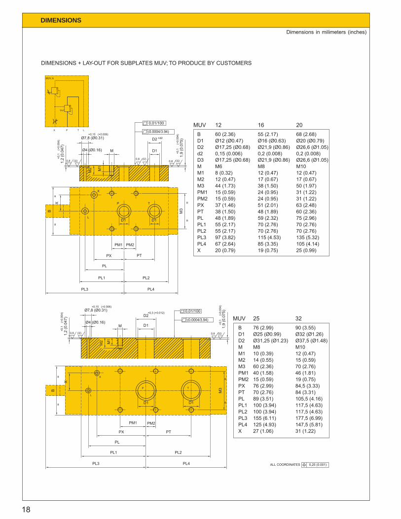
DIMENSIONS + LAY-OUT FOR SUBPLATES MUV; TO PRODUCE BY CUSTOMERS
MUV..A
135 (5.32)97 (3.82) 115 (4.53)PL3
XPL4 85 (3.35)
19 (0.75)20 (0.79)67 (2.64)
25 (0.99)105 (4.14)
PL
PL2PL1
PTPX
PM1PM2
M3
M1M2
M
70 (2.76)70 (2.76)
48 (1.89)59 (2.32)
51 (2.01)
48 (1.89)
55 (2.17)55 (2.17)
38 (1.50)37 (1.46)
75 (2.96)
70 (2.76)70 (2.76)
60 (2.36)63 (2.48)
M8
17 (0.67)12 (0.47)
38 (1.50)24 (0.95)24 (0.95)
15 (0.59)15 (0.59)
44 (1.73)
8 (0.32)12 (0.47)
M6
31 (1.22)31 (1.22)
50 (1.97)
12 (0.47)17 (0.67)
M10
Ø26,6 (Ø1.05)
Ø26,6 (Ø1.05)d2D3
D2
BD1
MUV
0,2 (0.008)
55 (2.17)Ø16 (Ø0.63)Ø21,9 (Ø0.86)
Ø21,9 (Ø0.86)0,15 (0.006)Ø17,25 (Ø0.68)
Ø17,25 (Ø0.68)
Ø12 (Ø0.47)60 (2.36)
0,2 (0.008)
68 (2.68)Ø20 (Ø0.79)
1612 20
ALL COORDINATES 0,25 (0.001)
Dimensions in milimeters (inches)

19
DIMENSIONS
D1
PT
PL2
PL4
PL
PL1
PL3
PL2
PL4
Ø7,8 (Ø0.31)
Ø4 (Ø0.16)
PL
PL1
PL3
B
1,2
(0.0
47)
X
D1
PX
PM1 PM2
D1
D2
M
M2 M1
Ø4 (Ø0.16)
M2
Ø7,8 (Ø0.31)
PX
B
X1,
2 (0
.047
)
M3
PT
PM1 PM2
D1
M
M1
D1
1,9
(0.0
75)
D1
D2
M3
1,9
(0.0
75)
0,01/100
==
+0,3 (+0.012)
==
0,8
+0,1
(
+0.0
04)
0,8
+0,15 (+0.006)
==
0,01/100
==
0,8
+d2
+0,1
(+
0.00
4)
(32)
(0.0004/3.94)
(32) (32)
+0,1
(+
0.00
4)
(32)0,8
+0,15 (+0.006)
+0,1
(
+0.0
04)
0,8 (32)
(0.0004/3.94)
L
X
L
X
70 (2.76)M3 60 (2.36)
125 (4.93)155 (6.11)100 (3.94)100 (3.94)
XPL4
27 (1.06)
PL2PL3
PL1
31 (1.22)147,5 (5.81)
117,5 (4.63)177,5 (6.99)
117,5 (4.63)
PX 76 (2.99)PTPL
70 (2.76)89 (3.51)
PM1PM2
40 (1.58)15 (0.59)
84,5 (3.33)84 (3.31)105,5 (4.16)
46 (1.81)19 (0.75)
MDM90 (3.55)B 76 (2.99)
Ø31,25 (Ø1.23)Ø25 (Ø0.99)
M8M
M2M1
14 (0.55)10 (0.39)
D2D1
M10
15 (0.59)12 (0.47)
Ø37,5 (Ø1.48)Ø32 (Ø1.26)
25 32
DIMENSIONS + LAY-OUT FOR SUBPLATES MDM; TO PRODUCE BY CUSTOMERS
X P LH PR
MDM..A
PR HP
PR PH
135 (5.32)97 (3.82) 115 (4.53)PL3
XPL4 85 (3.35)
19 (0.75)20 (0.79)67 (2.64)
25 (0.99)105 (4.14)
PL
PL2PL1
PTPX
PM1PM2
M3
M1M2
M
70 (2.76)70 (2.76)
48 (1.89)59 (2.32)
51 (2.01)
48 (1.89)
55 (2.17)55 (2.17)
38 (1.50)37 (1.46)
75 (2.96)
70 (2.76)70 (2.76)
60 (2.36)63 (2.48)
M8
17 (0.67)12 (0.47)
38 (1.50)24 (0.95)24 (0.95)
15 (0.59)15 (0.59)
44 (1.73)
8 (0.32)12 (0.47)
M6
31 (1.22)31 (1.22)
50 (1.97)
12 (0.47)17 (0.67)
M10
Ø26,6 (Ø1.05)
Ø26,6 (Ø1.05)d2D3
D2
BD1
MDM
0,2 (0.008)
55 (2.17)Ø16 (Ø0.63)Ø21,9 (Ø0.86)
Ø21,9 (Ø0.86)0,15 (0.006)Ø17,25 (Ø0.68)
Ø17,25 (Ø0.68)
Ø12 (Ø0.47)60 (2.36)
0,2 (0.008)
68 (2.68)Ø20 (Ø0.79)
1612 20
ALL COORDINATES 0,25 (0.001)
Dimensions in milimeters (inches)
20
DIMENSIONS
PL4
PXZ
PL2
PAB
PAB
D4
PL4
D4
D4
M3
PT1
PL1
PL3
D3
B
D2D2 PM1
PB PA
PT2
PM2
PM4PM3
D1
D1
D3
M1
M2
M D2
D5 1,9
(0.0
75)
M1
M2
M3
D1
PL1
PL3
B
1,2
(0.0
47)
1,9
(0.0
75)
Ø4 (Ø0,16)
D3 Ø7,8 (Ø0,31)
M D4
D3
D2
PT2
PXZ
PL2
PM1
PB PA
PM2
PT1
D2 D4
XZ
D1
ZX
==
==
+d3 +d3 +d5
= ==
=
+d3
+0,1
(+0.
004)
+0,15 (+0.006)+d3
(0.0004/3.94)
0,01/100
D2
+0,1
(+0.
004)
0,8 (32) (32)0,8(32)0,8
+0,1
(+0.
004)
(32)0,8(32)0,8
(0.0004/3.94)
0,01/100
(32)0,8
T1
B
B
P T2
A
AX
Z
T1 B P
Z
XA T2
85 (3.35)70 (2.76)55 (2.17)PL1
9 (0.35)Z
PL4PL3
PXZ
PL2
X
123 (4.85)
9 (0.35)49 (1.93)
123 (4.85)55 (2.17)
15 (0.59)10 (0.39)
148 (5.83)
10 (0.39)64 (2.52)
148 (5.83)70 (2.76)
169 (6.66)
15 (0.59)77 (3.03)
169 (6.66)85 (3.35)
19 (0.75)PA
PT2PT1PM2PM1PB
26,6 (1.05)
38 (1.05)38 (1.50)
26,6 (1.05)19 (0.75)
D4
M3M2M1M
33 (1.30)14 (0.55)
M69 (0.35)
Ø12 (Ø0.47)
30 (1.18)24 (0.95)
30 (1.18)
48 (1.89)48 (1.89)
30 (1.18)24 (0.95)
43 (1.69)
60 (2.36)60 (2.36)
43 (1.69)30 (1.18)
40 (1.58)15 (0.59)
Ø14 (Ø0.55)M8
12 (0.47)
50 (1.97)17 (0.67)
M1012 (0.47)
Ø18 (0.008)
Ø17,25 (Ø0.68)d3D3D2D1B
0,15 (0.006)
Ø11 (Ø0.43)
46 (1.81)Ø12 (Ø0.47)
MEV 12
0,2 (0.008)Ø21,9 (Ø0.86)Ø14 (Ø0.55)Ø16 (Ø0.63)55 (2.17)
Ø26,6 (Ø1.05)0,2 (0.008)
Ø17 (Ø0.67)
68 (2.68)Ø20 (Ø0.79)
16 20
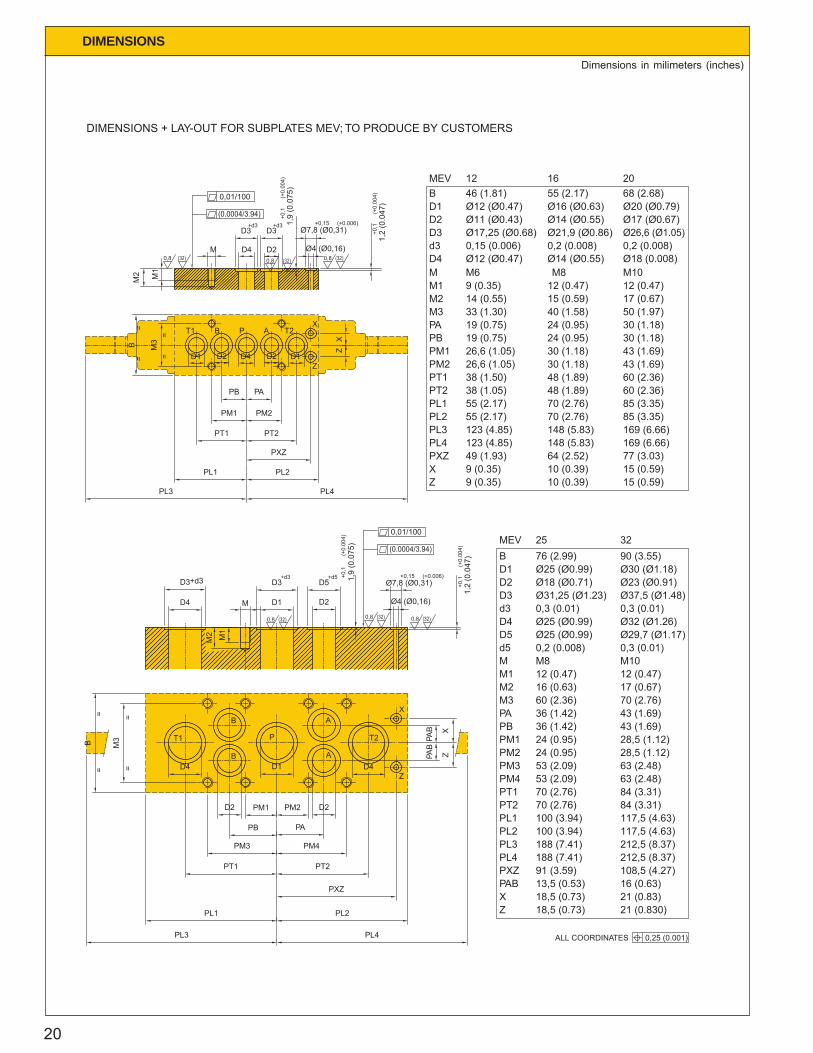
DIMENSIONS + LAY-OUT FOR SUBPLATES MEV; TO PRODUCE BY CUSTOMERS
PL4
XZ
PABPXZ
PL3PL2
PT2PL1
PT1
212,5 (8.37)188 (7.41)
18,5 (0.73)18,5 (0.73)
13,5 (0.53)91 (3.59)
21 (0.83)21 (0.830)
16 (0.63)108,5 (4.27)
188 (7.41)100 (3.94)100 (3.94)70 (2.76)70 (2.76)
117,5 (4.63)
212,5 (8.37)117,5 (4.63)
84 (3.31)84 (3.31)
Ø29,7 (Ø1.17)Ø25 (Ø0.99)D5
PM3PM4
PM2
PBPM1
PA
M1M2M3
d5M
53 (2.09)53 (2.09)
24 (0.95)
36 (1.42)24 (0.95)
36 (1.42)
63 (2.48)63 (2.48)
28,5 (1.12)
43 (1.69)28,5 (1.12)
43 (1.69)
12 (0.47)16 (0.63)60 (2.36)
0,2 (0.008)M8
12 (0.47)17 (0.67)70 (2.76)
0,3 (0.01)M10
B
D3
D4d3
D2D1
MEV90 (3.55)76 (2.99)
Ø31,25 (Ø1.23)0,3 (0.01)Ø25 (Ø0.99)
Ø25 (Ø0.99)Ø18 (Ø0.71)
Ø37,5 (Ø1.48)0,3 (0.01)Ø32 (Ø1.26)
Ø23 (Ø0.91)Ø30 (Ø1.18)
25 32
ALL COORDINATES 0,25 (0.001)
1,2
(0.0
47)
Ø4 (Ø0,16)
Ø7,8 (Ø0,31)+0,15 (+0.006)
+0,1
(+0.
004)
Dimensions in milimeters (inches)
21
MAINTENANCE DATA
Mounting procedure
- AMCA-valves shall not be mounted byovertightening of mounting bolts, causingmechanical distortion and thus spool lock. (seetightening torques).
- Mounting on flat surface, flatness 0,01/100 mm(0.0004/3.9 inch).
- Don’t use conical thread for port-fittings.- For sealing purposes, use O-rings.- At the port-connections at the sub-plates, the B-
port shall be connected to the line with the largestreturn-flow (e.g. piston-side of differential cylinder),because in the valve the distance B-T is shorterthan A-T.
- Check the voltage and current of the solenoids,before operation.
- Avoid ingression of contaminants during mounting.
Start-up procedure
- Start the system-flushing procedure with theadjustment-screw of relief valve (see fig. 29-31,(1) on page 22) fully released to achieve theminimum pressure.
- Turning the adjustment-screw clockwise (360 turn= ca. 100 bar (143 psi)), the maximum load-pressurerises up to the desired level. (max. 350 bar (5000psi)). During this adjustment the end-users (cylinderand/or motor) should be blocked.
- Check the valve-function and the tightness offittings etc.
- Use the stroke limiting screws to bleed the end-caps, during system bleeding.
Adjustment procedure
MDM/MUV
To avoid instability of the MDM- or MUV-spool, thedamping-screw (see fig. 32, (2) on page 22) is factory-setted. Adjustment on location is possible as follows:
- Remove the cover-screw (width 5 mm (0.2 inch))- Adjust the damping with the damping-screw (width
5 mm (0.2 inch)), turning clockwise or anti-clockwise for more or less throttling.
Note: Don’t throttle too much especially in the caseof MDM otherwise the load signal can be disturbed.
Valve response time
The valve response time is adjustable from 0,24 -10 seconds. Adjustment screws are on the pilot stagebelow the solenoids.
- Turn the adjustment screws clockwise to enlargevalve response time.
- Turn the adjustment screws anti-clockwise toshorten valve response time.
Flow-adjustment
Factory-setting of flows, as ordered in ordering code.If, after long life-cycle, re-adjustment should benecessary, two possibilities are available, dependingon the configuration:
1. Stroke limiter (see fig. 33, (5) on page 22)- Remove cover-screw of stroke limiter- Loosen the lock-nut (width 13 mm (0.51 inch))- Turn the stroke limiting screw (width 4 mm (0.16
inch)) clockwise to reduce flow and anti-clockwiseto enlarge flow.
2. ∆p adjustment (see page 26)- Loosen the lock-nut (width 13 mm (0.51 inch))- Turn the adjustment screw (width 4 mm (0.16 inch))
clockwise to enlarge the preset spring-force, toachieve more flow. (anti-clockwise to reduce flow)
- Tighten lock-nut.
Note: If the flow through A-port is sufficient andthe flow through B-port should be enlarged, adjustfirst the B-flow by ∆p-adjustment and reduce afterthat the A-flow by stroke limitation.
Fluid maintenance
Due to the construction, these AMCA-valves, arenot highly susceptible to particulate (silt type) lock,nor to contaminant wear. Therefore the contaminantsensitivity is very low.
- Use mineral oil (recommended ISO/VG-32). Otherfluids on request.
- Keep the contamination level better or equal NAS1638 class 9 or ISO 18/15.

22
Fig. 33Fig. 33Fig. 32Fig. 32
Fig. 29,30 and 31Fig. 29,30 and 31
2
MUV..A
A..UVA..DMA..UV/R
MDM..A1
TP
3 4
MUV..A
A..UV
P RT
A..UV/R
1 3
MUV..A
4
PT
A..DM
1
MDM..A
3A 4
8
5
6
T
b
8
5
9
6
PT
7
a
A B
A..EV
MEV..A
TROUBLE SHOOTING
A. System pressure too low or set pressurecannot be reached
1. Relief valve cartridge fouledDirt particles jammed between cone and seat ofrelief valve (1) and prevent pressure being builtup.Turn adjustment anti-clock wise, switch adirectional valve several times. If necessary,dismantle (a M4 bolt assists in removing thespringcup). If damaged, replace cone and seat.Examine the system filter.
2. Damping throttle (2) blocked (dir t ormaladjustment).If necessary, remove, clean and replace.Adjust to 1 1/2 - 2 1/2 turns from fully closedposition. Find the right damping position. Turn thethrottle only by unloaded pump.
3. MUV-spool (3) or MDM-spool (3A) jammed openWhen removing lower end-cover (4) the springshould push out of the spool. Remove andexamine the spool and bore for damage. Deburrwith care. Flush the spool to remove dirt.
4. Faults in other components of the systemDamaged pump, motor, seals etc.
Note: The set pressure can only be reached if acylinder is at the end of its stroke or a motoris stalled.
B. User moves erratically1. Air in system
Bleed both end-caps with stroke limiting screws(5).Slacken bolts (6) fixing the solenoids to body andretighten after repeated operation.
2. Pilot valve faultyFit a pressure gauge in place of the stroke limitingscrews to observe pilot pressure.If persistent, swap pilot stage (7) to anothersection to detect faulty unit.
3. Excessive friction of directional spoolRemove both end-caps (8) and examine spool(9) and bore from dirt or damage. Deburr with care.Examine system filter.
Also spool lock, when mounting faces are notflat.
4. Excessive dampingSee B2.
5. Excessive friction in other components of thesystem
C. User does not move or moves at slow speed1. Damping throttle blocked or dirty
See A2.
2. Relief valve setting too lowSee A1.
3. Directional spool does not shiftSee B3.
4. MUV or MDM-spool jammed openSee A3.
5. There is insufficient user load.
6. Filter in returnline is contaminated.
D. Pump does not unload1. MUV-spool jammed (see A3)
2. Directional spool not centringExcessive friction (see B3).Electrical fault. Check the electrical circuit.
Fig.29 Fig.30 Fig.31 Fig.32
Fig.31
23
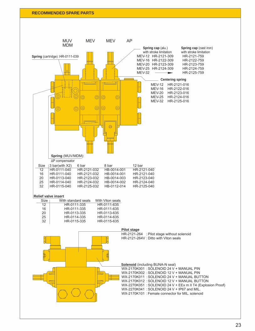
RECOMMENDED SPARE PARTS
HB-0014-003HB-0014-002HB-0112-014
HB-0014-001HB-0014-001
8 bar
Relief valve insert Size
HR-0115-335
HR-0111-335HR-0111-335
HR-0114-335HR-0113-33520
3225
1216
MEVMDMMUV MEV AP
Size
Spring (MUV/MDM):∆P compensator
2532
1620 HR-0113-040
HR-0115-040HR-0114-040
HR-0111-04012
3 bar(with X2)HR-0111-040
HR-2123-032HR-2124-032HR-2125-032
HR-2121-032HR-2121-0326 bar
SOLENOID 24 V + EEx m II T4 (Explosion Proof)
SOLENOID 24 V + MANUAL BUTTONSOLENOID 12 V + MANUAL PINSOLENOID 24 V + MANUAL PIN
SOLENOID 24 V + IP67 and MIL.
SOLENOID 12 V + MANUAL BUTTONWX-2270K051 :WX-2270K041 :
Female connector for MIL. solenoidWX-2170K101 :
WX-2170K012 :WX-2170K011 :WX-2170K002 :WX-2170K001 :Solenoid (including BUNA-N seal)
Spring cap (cast iron)Spring cap (alu.)
HR-2121-309HR-2122-309HR-2123-309HR-2124-309
MEV-20MEV-25MEV-32
MEV-12MEV-16
HR-2124-759HR-2123-759HR-2122-759HR-2121-759
HR-2125-759
HR-2121-040HR-2123-040
HR-2125-040HR-2124-040
HR-2121-04012 bar
Centering spring
MEV-32MEV-25MEV-20MEV-16MEV-12 HR-2121-016
HR-2123-016HR-2124-016HR-2125-016
HR-2122-016
Spring (cartridge) :HR-0111-039
HR-2121-264 : Pilot stage without solenoidHR-2121-264V : Ditto with Viton seals
Pilot stage
With standard sealsHR-0111-635
HR-0115-635
HR-0111-635
HR-0114-635HR-0113-635
With Viton seals
with stroke limitation with stroke limitation
24
RECOMMENDED SPARE PARTS
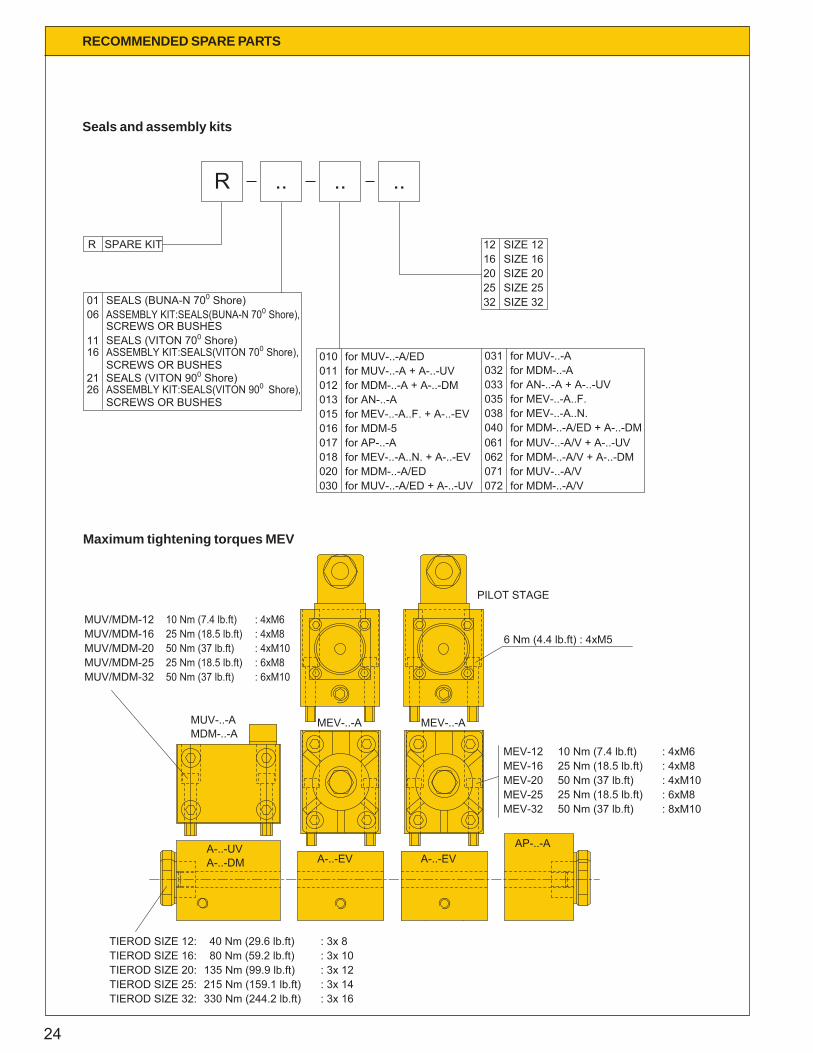
6 Nm (4.4 lb.ft) : 4xM5
40 Nm (29.6 lb.ft)
330 Nm (244.2 lb.ft)215 Nm (159.1 lb.ft)135 Nm (99.9 lb.ft)80 Nm (59.2 lb.ft)TIEROD SIZE 16:
TIEROD SIZE 25:TIEROD SIZE 32:
TIEROD SIZE 20:
TIEROD SIZE 12:
MUV/MDM-12MUV/MDM-16
MUV/MDM-25MUV/MDM-20
MUV/MDM-32
10 Nm (7.4 lb.ft)
25 Nm (18.5 lb.ft)
25 Nm (18.5 lb.ft)50 Nm (37 lb.ft)
50 Nm (37 lb.ft)
MEV-12MEV-16MEV-20MEV-25MEV-32
10 Nm (7.4 lb.ft)25 Nm (18.5 lb.ft)50 Nm (37 lb.ft)25 Nm (18.5 lb.ft)50 Nm (37 lb.ft)
A-..-DMA-..-UV
MDM-..-AMUV-..-A
A-..-EVA-..-EVAP-..-A
PILOT STAGE
for MDM-..-A/EDfor MUV-..-A/ED + A-..-UV
for MUV-..-A/ED
for MEV-..-A..F. + A-..-EV
for MDM-..-A + A-..-DM
for MEV-..-A..N. + A-..-EV
for MUV-..-A + A-..-UV
for MDM-5016for AP-..-A
020030
018017
for AN-..-A015013
011012
010
SEALS (BUNA-N 700 Shore)ASSEMBLY KIT:SEALS(BUNA-N 700 Shore),
SEALS (VITON 700 Shore)
SEALS (VITON 900 Shore)
ASSEMBLY KIT:SEALS(VITON 700 Shore),SCREWS OR BUSHES
ASSEMBLY KIT:SEALS(VITON 900 Shore),SCREWS OR BUSHES
SCREWS OR BUSHES
2126
1611
0601
for MUV-..-A/V + A-..-UVfor MDM-..-A/V + A-..-DMfor MUV-..-A/Vfor MDM-..-A/V
for MUV-..-Afor MDM-..-Afor AN-..-A + A-..-UV
for MEV-..-A..N.for MEV-..-A..F.
for MDM-..-A/ED + A-..-DM040
072071062061
038035
032033
031
: 3x 16: 3x 14
: 3x 10: 3x 12
: 3x 8
: 6xM10: 6xM8: 4xM10: 4xM8: 4xM6
: 4xM10: 4xM8
: 8xM10: 6xM8
: 4xM6
MEV-..-A MEV-..-A
SPARE KITR
SIZE 3232
SIZE 12SIZE 16SIZE 20SIZE 25
2025
1216
R .. .. ..
Seals and assembly kits
Maximum tightening torques MEV

25
7: AP 16 A
5: MEV 16 ASFFA 50/1006: A 16 EV
3: MEV 16 ASFFA 100/1004: A 16 EV
2: A 16 UV/X1: MUV 16 AS6S
4
7
6
2
1
3
5
Example for Ordering
One electrically controlled directional control valve assembly, nominal bore 16, mounting type; sub-plate, consistsof:
1. MUV Pressure relief valve, ∆p compensator 6 bar (86 psi)
2. A..UV/X Inlet plate for ganged sub-plate and pressure relief valve with X connection for remote control
3. MEV 4/3 way controlvalve, spool type A, flow range 100 l/min (26 USgpm) (at ports A + B , with springreturn to neutral position and adjustable flow limiter
4. A..EV Sub-plate for 4/3 way valve, standard
5. MEV 4/3 way controlvalve, spool type A, flow range at port A = 50 l/min (13 USgpm) port B = 100 l/min(26 USgpm) with spring return to neutral position and adjustable flow limiter
6. A..EV Sub-plate for 4/3 way control valve, standard
7. AP..A AP endplate, standard
(Ordering codes see page 26, 27, 28 and 29)
ORDER EXAMPLE
26
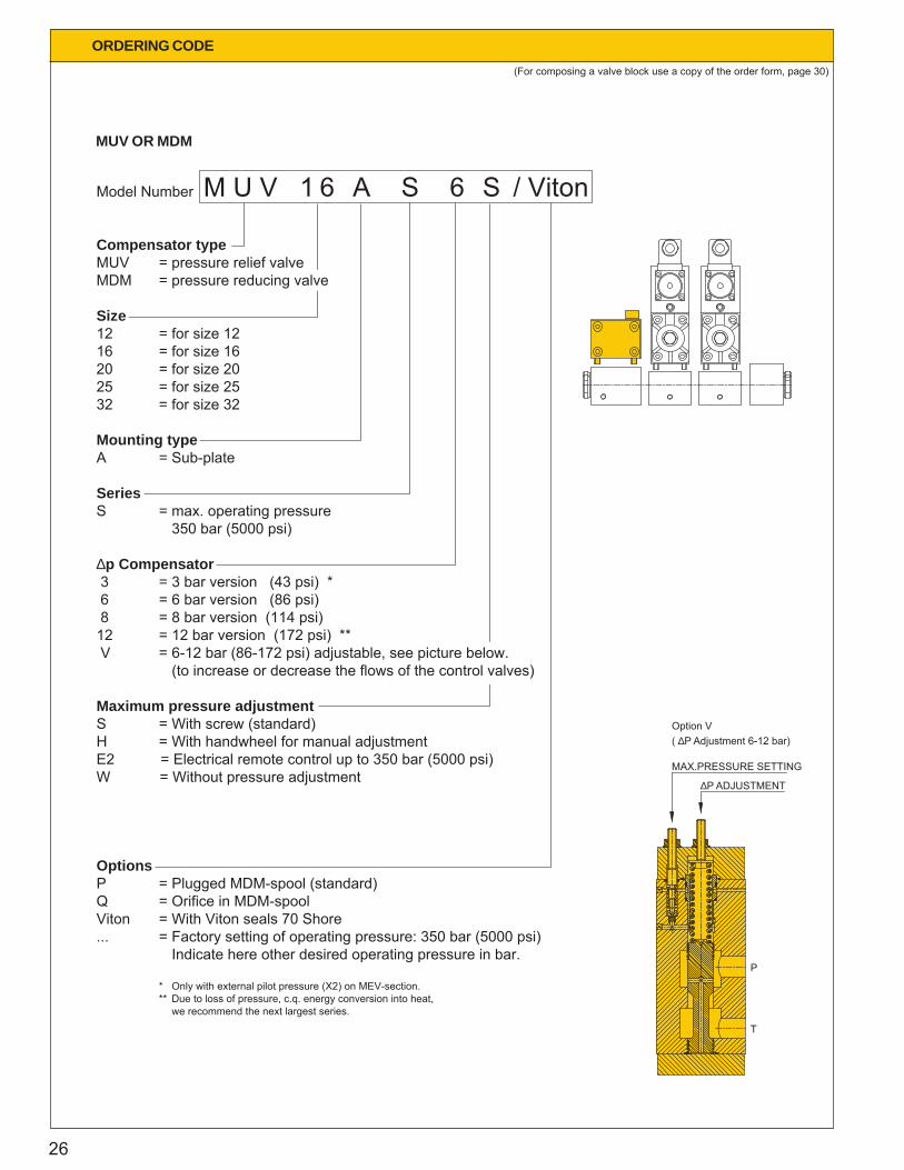
M U V 1 6 A S 6 S / VitonModel Number
Compensator typeMUV = pressure relief valveMDM = pressure reducing valve
Size12 = for size 1216 = for size 1620 = for size 2025 = for size 2532 = for size 32
Mounting typeA = Sub-plate
SeriesS = max. operating pressure 350 bar (5000 psi)
∆p Compensator 3 = 3 bar version (43 psi) * 6 = 6 bar version (86 psi) 8 = 8 bar version (114 psi)12 = 12 bar version (172 psi) ** V = 6-12 bar (86-172 psi) adjustable, see picture below. (to increase or decrease the flows of the control valves)
Maximum pressure adjustmentS = With screw (standard)H = With handwheel for manual adjustmentE2 = Electrical remote control up to 350 bar (5000 psi)W = Without pressure adjustment
OptionsP = Plugged MDM-spool (standard)Q = Orifice in MDM-spoolViton = With Viton seals 70 Shore... = Factory setting of operating pressure: 350 bar (5000 psi) Indicate here other desired operating pressure in bar.
* Only with external pilot pressure (X2) on MEV-section.** Due to loss of pressure, c.q. energy conversion into heat,
we recommend the next largest series.
ORDERING CODE
(For composing a valve block use a copy of the order form, page 30)
MUV OR MDM
T
P
MAX.PRESSURE SETTING
∆P ADJUSTMENT
Option V( ∆P Adjustment 6-12 bar)

27
AN 1 6 A / T 2Model Number
SeriesAN = Inlet plate*
Size12 = for size 1216 = for size 1620 = for size 2025 = for size 2532 = for size 32
Mounting typeA = Sub-plate
OptionsSAE = S.A.E. straight thread ‘O’RING BOSST2 = 2nd tankportViton = With Viton seals
* AN = Inlet plate for use with variable displacement pump (L.S. pump) or two valve systems in parallel use, with one MUV. Standard with X-port in sub-plate
A 1 6 U V / T 2Model Number
SeriesA = Sub-plate
Size12 = for size 1216 = for size 1620 = for size 2025 = for size 2532 = for size 32
Sub-plateUV = for MUVDM = for MDM
OptionsR = allows serial connection with 2nd MUV (only for sub-plate UV)SAE = S.A.E. straight thread O RING BOSST2 = 2nd tankport (only for sub-plate UV)Viton = With Viton sealsX = Remote Control Connection
(For composing a valve block use a copy of the order form, page 30)
INLETPLATE FOR GANGED SUB-PLATES
ORDERING CODE
INLETPLATE FOR GANGED SUB-PLATES (WITHOUT MOUNTED MUV OR MDM)

28
ORDERING CODE
MEV 16 A S F F A 50/50 / T3 / X2 / A Model Number
Series MEV = Directional control valve, electrically controlled
Size12 = for size 1216 = for size 1620 = for size 2025 = for size 2532 = for size 32
Mounting typeA = Sub-plate
SeriesS = Max. operating pressure
350 bar (5000 psi)
Position lockF = Spring return (spring ctr)
Control systemN = on/offF = proportional
Spool typeA, B, C, D, E, F, G, K, M or O. See page 2
Maximum Flow (l/min).../... = choose the flow for port A and port B (see for max. flows page 2 , choose the flow in combination with the ∆p compensator)
In case of differing flow ranges for ports A + B, the range for port A is given first,followed by the range for B, eg. 50/100.
OptionsACS = Adjustable Centering SpringsG = Cast iron spring capsJS = Additional connection for hydraulical controlM = Additional manual controlMSW = Additional manual control Seawater ResistantN = Neutral spool position signal, through inductive switchSAE = S.A.E. straight thread ‘O’RING BOSS (Option T3 and/or X2)T3 = External pilot drainViton = With Viton sealsX2 = External pilot pressure
Solenoid typesA = 12V DC IP65 with emergency control by pinB = 24V DC IP65 with emergency control by pin (standard)E = 12V DC IP65 with emergency control by button F = 24V DC IP65 with emergency control by button H = 24V DC IP57 EEx m II T4 (Explosion Proof)J = 24V DC IP67 Military, without female connector
(For composing a valve block use a copy of the order form, page 30)
CONTROL VALVE (MEV)
29
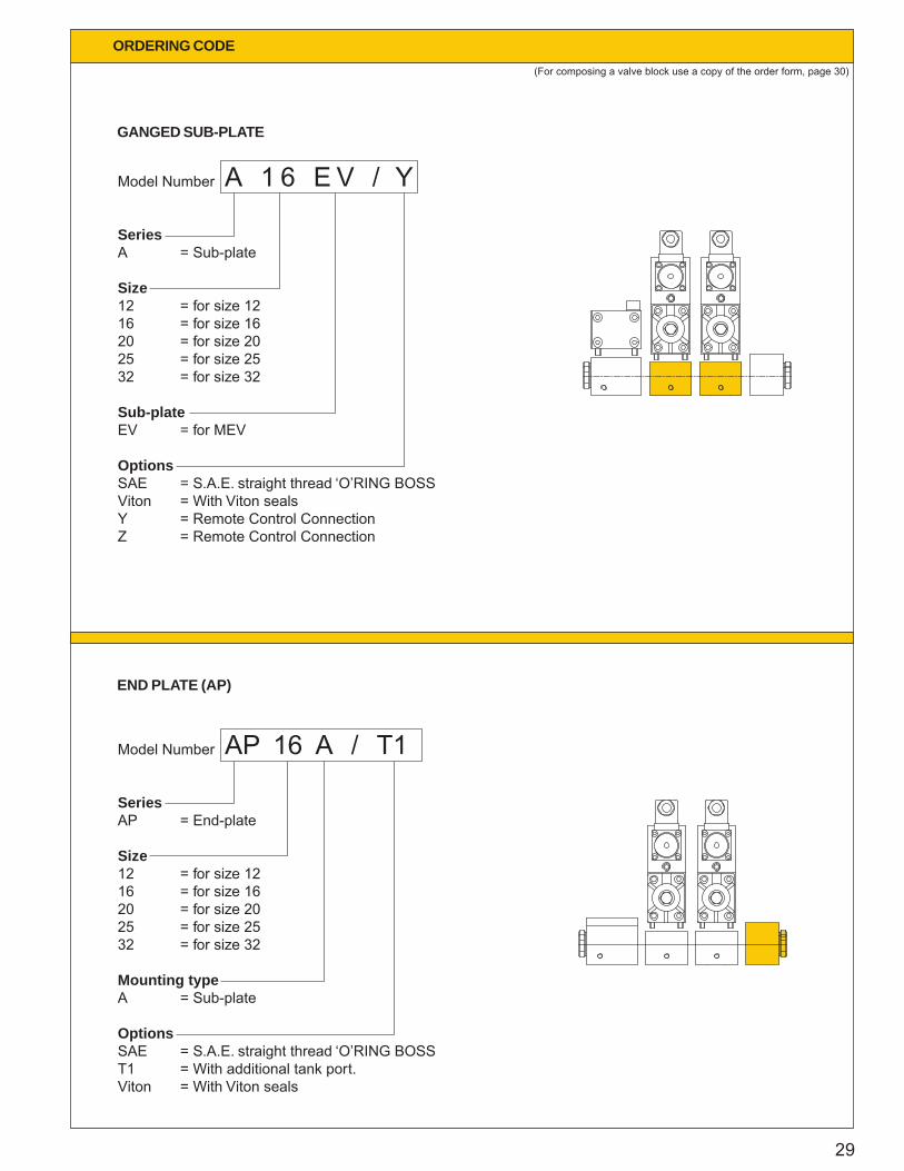
AP 16 A / T1Model Number
SeriesAP = End-plate
Size12 = for size 1216 = for size 1620 = for size 2025 = for size 2532 = for size 32
Mounting typeA = Sub-plate
OptionsSAE = S.A.E. straight thread ‘O’RING BOSS T1 = With additional tank port.Viton = With Viton seals
A 1 6 E V / YModel Number
SeriesA = Sub-plate
Size12 = for size 1216 = for size 1620 = for size 2025 = for size 2532 = for size 32
Sub-plateEV = for MEV
OptionsSAE = S.A.E. straight thread ‘O’RING BOSS Viton = With Viton sealsY = Remote Control ConnectionZ = Remote Control Connection
(For composing a valve block use a copy of the order form, page 30)
GANGED SUB-PLATE
ORDERING CODE
END PLATE (AP)
30
Company
Name
Order No.
Quantity(complete system)
Date :
:
:
:
:
(stamp)
MUV or MDM
INLET PLATE
INLET PLATE
M
A
AN
A
MEV1
2MEV
A
3MEV
A
4MEV
A
5MEV
A
6MEV
A
7MEV
A
8MEV
A
END PLATE AP
AS
EV
EV
EV
EV
EV
EV
EV
EV
A
AS
AS
AS
AS
AS
AS
AS
AS
F
F
F
F
F
F
F
F
SUBPLATE
GANGED
MEV +
Size
Spool type
Flow
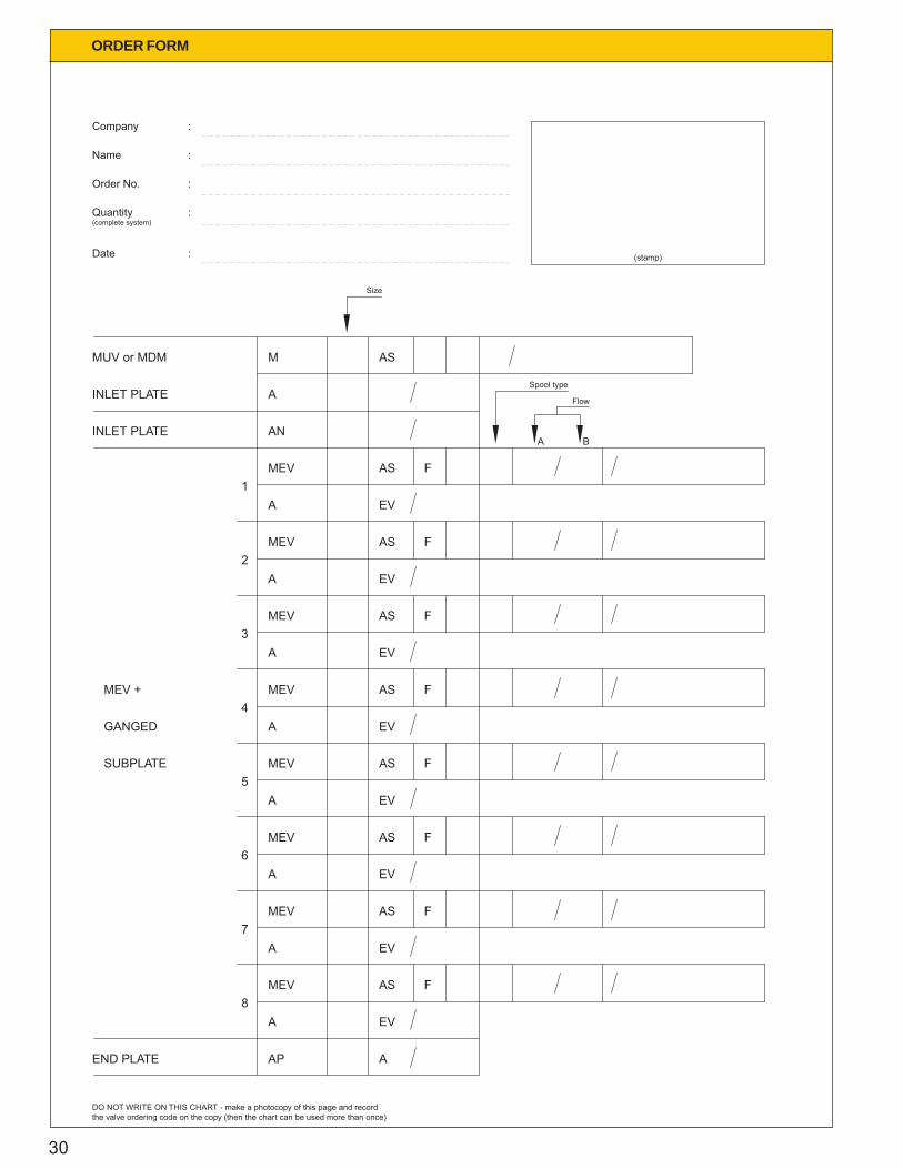
DO NOT WRITE ON THIS CHART - make a photocopy of this page and recordthe valve ordering code on the copy (then the chart can be used more than once)
A B
ORDER FORM

31
NOTES

Your local representative