mh 1 profile plus - martin professional 6 rush™ mh 1 profile plus user manual do not connect...
TRANSCRIPT
MH 1 Profile Plus
User Manual

© 2013-2015 Martin Professional ApS. Information subject to change without notice. Martin Professional and all affiliated companies disclaim liability for any injury, damage, direct or indirect loss, consequential or economic loss or any other loss occasioned by the use of, inability to use or reliance on the information contained in this manual. The Martin logo, the RUSH logo, the RUSH name, the Martin name and all other trademarks in this document pertaining to services or products by Martin Professional or its affiliates and subsidiaries are trademarks owned or licensed by Martin Professional or its affiliates or subsidiaries.
Martin Professional • Olof Palmes Allé 18 • 8200 Aarhus N • Denmark • www.martin.com
Manual: Revision D
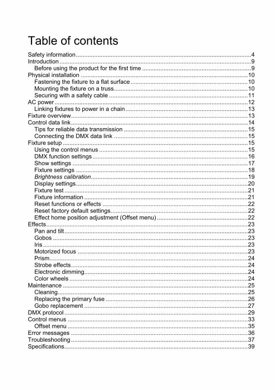
Table of contents Safety information .......................................................................................................... 4 Introduction .................................................................................................................... 9
Before using the product for the first time .................................................................. 9 Physical installation ..................................................................................................... 10
Fastening the fixture to a flat surface ....................................................................... 10 Mounting the fixture on a truss ................................................................................. 10 Securing with a safety cable .................................................................................... 11
AC power ..................................................................................................................... 12 Linking fixtures to power in a chain .......................................................................... 13
Fixture overview ........................................................................................................... 13 Control data link ........................................................................................................... 14
Tips for reliable data transmission ........................................................................... 15 Connecting the DMX data link ................................................................................. 15
Fixture setup ................................................................................................................ 15 Using the control menus .......................................................................................... 15 DMX function settings .............................................................................................. 16 Show settings .......................................................................................................... 17 Fixture settings ........................................................................................................ 18 Brightness calibration ............................................................................................... 19 Display settings ........................................................................................................ 20 Fixture test ............................................................................................................... 21 Fixture information ................................................................................................... 21 Reset functions or effects ........................................................................................ 22 Reset factory default settings ................................................................................... 22 Effect home position adjustment (Offset menu) ....................................................... 22
Effects .......................................................................................................................... 23 Pan and tilt ............................................................................................................... 23 Gobos ...................................................................................................................... 23 Iris ............................................................................................................................ 23 Motorized focus ....................................................................................................... 23 Prism ........................................................................................................................ 24 Strobe effects ........................................................................................................... 24 Electronic dimming ................................................................................................... 24 Color wheels ............................................................................................................ 24
Maintenance ................................................................................................................ 25 Cleaning ................................................................................................................... 25 Replacing the primary fuse ...................................................................................... 26 Gobo replacement ................................................................................................... 27
DMX protocol ............................................................................................................... 29 Control menus ............................................................................................................. 33
Offset menu ............................................................................................................. 35 Error messages ........................................................................................................... 36 Troubleshooting ........................................................................................................... 37 Specifications ............................................................................................................... 39

4 RUSH™ MH 1 Profile Plus user manual
Safety information
WARNING!
Read the safety precautions in this manual before installing, operating or servicing this product.
The following symbols are used to identify important safety information on the product and in this manual:
Warning!
Safety hazard. Risk of severe
injury or death.
Warning!
Powerful light emission. Risk of eye injury.
Warning!
See user manual for important
safety information.
Warning!
Hazardous voltage. Risk of lethal or
severe electric shock.
Warning!
Hot surfaces and fire hazard.
Warning! Risk Group 2 product according to EN 62471. Do not stare directly into the beam. Do not view the light output with optical instruments or any device that may concentrate the beam.
This lighting fixture is for professional use only and must be installed by a qualified technician. It is not for household use. It presents risks of severe injury or death due to fire hazards, electric shock and falls. It produces a powerful, concentrated beam of light that can create a fire hazard or a risk of eye injury if the safety precautions below are not followed.
Install, operate and service RUSH by Martin™ products only as directed in their user manuals, or you may create a safety hazard or cause damage that is not covered by product warranties.
Follow the safety precautions listed below and observe all warnings in this manual and printed on the product. Keep this user manual for future use.

RUSH™ MH 1 Profile Plus user manual 5
For the latest user documentation and other information for this and all Martin™ products, please visit the Martin website at http://www.martin.com
If you have any questions about how to install, operate or service the fixture safely, please contact your Martin™ distributor (see www.martin.com/distributors for details) or call the Martin™ 24-hour service hotline on +45 8740 0000, or in the USA on 1-888-tech-180.
Respect all locally applicable laws, codes and regulations when installing, operating or servicing the fixture.
Protection from electric shock
Do not expose the fixture to rain or moisture.
Disconnect the fixture from AC power before carrying out any installation or maintenance work and when the fixture is not in use.
Ensure that the fixture is electrically connected to ground (earth).
Use only a source of AC power that complies with local building and electrical codes and has both overload and ground-fault (earth-fault) protection.
Socket outlets or external power switches used to supply the fixture with power must be located near the fixture and easily accessible so that the fixture can easily be disconnected from power.
Replace defective fuses with ones of the specified type and rating only.
Isolate the fixture from power immediately if the power plug or any seal, cover, cable, or other component is damaged, defective, deformed, wet or showing signs of overheating. Do not reapply power until repairs have been completed
Before using the fixture, check that all power distribution equipment and cables are in perfect condition and rated for the electrical requirements of all connected devices.
Use only Neutrik PowerCon cable connectors to connect to power sockets.

6 RUSH™ MH 1 Profile Plus user manual
Do not connect devices to power in a chain that will exceed the electrical ratings of any cable or connector used in the chain.
The supplied power input cable is rated 6 A and can safely supply only one fixture with mains power. Do not connect any device to the fixture’s MAINS OUT connector when using this cable. If you replace this cable and also use the replacement cable to supply only one fixture with mains power, the replacement cable must also be rated 6 A minimum, have three conductors 18 AWG or 0.75 mm² minimum conductor size, have an outer cable diameter of 6 - 15 mm (0.2 - 0.6 in.) and be temperature-rated to suit the application. In the USA and Canada the cable must be UL listed, type SJT or equivalent. In the EU the cable must be type H05VV-F or equivalent.
To connect fixtures to mains power in a chain, you must first obtain 14 AWG or 1.5 mm2 power input and throughput cables that are 16 A rated and temperature-rated to suit the application. In the USA and Canada the cables must be UL-listed, type SJT or equivalent. In the EU the cables must be type H05VV-F or equivalent. Suitable cables with Neutrik PowerCon connectors are available from Martin™ (see Accessories on page 41). If you use these cables, you can connect fixtures to power in a linked chain, MAINS OUT throughput socket to MAINS IN input socket, but do not link more than:
• four (4) RUSH MH 1 fixtures in total at 100-120 V, or
• eight (8) RUSH MH 1 fixtures in total at 200-240 V.
The voltage and frequency at the MAINS OUT socket are the same as the voltage and frequency applied to the MAINS IN socket. Only connect devices to the MAINS OUT socket that accept this voltage and frequency.
Protection from burns and fire
Do not operate the fixture if the ambient temperature (Ta) exceeds 40° C (104° F).
The surface of the product casing can reach up to 55° C (131° F) during operation. Avoid contact by persons and materials. Allow the fixture to cool for at least 10 minutes before handling.

RUSH™ MH 1 Profile Plus user manual 7
Keep flammable materials well away from the fixture. Keep all combustible materials (e.g. fabric, wood, paper) at least 100 mm (4 in.) away from the fixture head.
Ensure that there is free and unobstructed airflow around the fixture. Provide a minimum clearance of 100 mm (4 in.) around fans and air vents.
Do not illuminate surfaces within 700 mm (27.6 in.) of the fixture.
Do not attempt to bypass thermostatic switches or fuses.
Do not stick filters, masks or other materials onto any optical component.
The fixture’s optical components can focus the sun’s rays, creating a risk of fire and damage. Do not expose the front of the fixture to sunlight or any other intense light source.
Protection from eye injury
Do not stare directly into the product’s light output.
Do not look at the light output with magnifiers, telescopes, binoculars or similar optical instruments that may concentrate the light output.
Ensure that persons are not looking directly into the LEDs when the product lights up suddenly. This can happen when power is applied, when the product receives a DMX signal, or when certain control menu items are selected.
To minimize the risk of eye irritation or injury, disconnect the fixture from power at all times when the fixture is not in use, and provide well-lit conditions to reduce the pupil diameter of anyone working on or near the fixture.
Protection from injury
Fasten the fixture securely to a fixed surface or structure when in use. The fixture is not portable when installed.
Ensure that any supporting structure and/or hardware used can hold at least 10 times the weight of all the devices they support.
If suspending from a rigging structure, fasten the fixture to a rigging clamp. Do not use safety cables as the primary means of support.
8 RUSH™ MH 1 Profile Plus user manual
If the fixture is installed in a location where it may cause injury or damage if it falls, install as directed in this manual a secondary attachment such as a safety cable that will hold the fixture if a primary attachment fails. The secondary attachment must be approved by an official body such as TÜV as a safety attachment for the weight that it secures, must comply with EN 60598-2-17 Section 17.6.6 and must be capable of bearing a static suspended load that is ten times the weight of the fixture and all installed accessories.
Allow enough clearance around the head to ensure that it cannot collide with an object or another fixture when it moves.
Check that all external covers and rigging hardware are securely fastened.
Block access below the work area and work from a stable platform whenever installing, servicing or moving the fixture.
Do not operate the fixture with missing or damaged covers, shields or any optical component.
Do not lift or carry the fixture by its head. Support the fixture by its base only.
In the event of an operating problem, stop using the fixture immediately and disconnect it from power. Do not attempt to use a fixture that is obviously damaged.
Do not modify the fixture in any way not described in this manual or install other than genuine RUSH by Martin™ parts.
Refer any service operation not described in this manual to a qualified technician.

RUSH™ MH 1 Profile Plus user manual 9
Introduction The MH 1 Profile Plus is a small, powerful profile fixture incorporating a 180 W long-life LED engine. It provides two gobo wheels, the first with seven rotating gobos and the second with eight fixed gobos. The fixture has two color wheels, each with eight colors (including white), smooth electronic dimming, rotating prism effects, a mechanical focus and iris, as well as strobe effects. The device is rugged, lightweight and compact, and is ideal for touring applications or small fixed installations.
The fixture can be controlled using any DMX-compliant controller. It can also function without DMX control as a standalone device running one of four pre-programmed shows, with the option of sound-activated scene triggering.
The fixture is supplied with this user manual, a 1.5 m (5 ft.) power cable (local power plug not included) and two omega brackets for rigging clamp attachment.
Before using the product for the first time
1. Read ’Safety information’ on page 4 before installing, operating or servicing the fixture.
2. Unpack and ensure that there is no transportation damage before using the fixture. Never attempt to operate a damaged fixture.
3. If the fixture is not going to be hard-wired to a mains supply, attach a local power plug (not supplied) to the end of the supplied power cable.
4. Before operating, ensure that the voltage and frequency of the power supply match the power requirements of the fixture.
5. Check the RUSH support pages on the Martin Professional website at www.martin.com for the most recent user documentation and technical information about the fixture. RUSH by Martin™ user manual revisions are identified by the revision letter at the bottom of the inside cover.
Note that whenever AC power is applied to the fixture, it will reset all effects and functions to their home positions. The fixture head will move. This process usually takes around 20 seconds.
10 RUSH™ MH 1 Profile Plus user manual
Physical installation
Warning! Read ‘Safety information’ on page 4 before installing the fixture.
The fixture is designed for indoor use only and must be used in a dry location with adequate ventilation. Ensure that none of the fixture’s ventilation slots are blocked and ensure that the fixture is fastened to a secure structure or surface.
Fastening the fixture to a flat surface
The fixture can be fastened to a hard, fixed, flat surface. Ensure that the surface can support at least 10 times the weight of all fixtures and equipment to be installed on it.
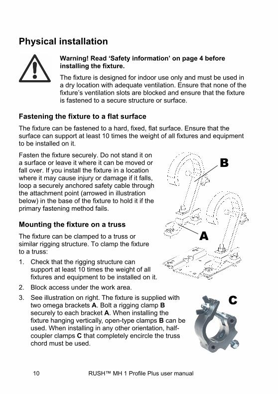
Fasten the fixture securely. Do not stand it on a surface or leave it where it can be moved or fall over. If you install the fixture in a location where it may cause injury or damage if it falls, loop a securely anchored safety cable through the attachment point (arrowed in illustration below) in the base of the fixture to hold it if the primary fastening method fails.
Mounting the fixture on a truss
The fixture can be clamped to a truss or similar rigging structure. To clamp the fixture to a truss:
1. Check that the rigging structure can support at least 10 times the weight of all fixtures and equipment to be installed on it.
2. Block access under the work area.
3. See illustration on right. The fixture is supplied with two omega brackets A. Bolt a rigging clamp B securely to each bracket A. When installing the fixture hanging vertically, open-type clamps B can be used. When installing in any other orientation, half-coupler clamps C that completely encircle the truss chord must be used.
C
A
B
RUSH™ MH 1 Profile Plus user manual 11
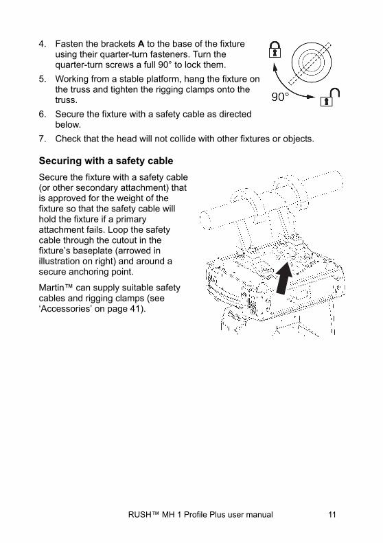
4. Fasten the brackets A to the base of the fixture using their quarter-turn fasteners. Turn the quarter-turn screws a full 90° to lock them.
5. Working from a stable platform, hang the fixture on the truss and tighten the rigging clamps onto the truss.
6. Secure the fixture with a safety cable as directed below.
7. Check that the head will not collide with other fixtures or objects.
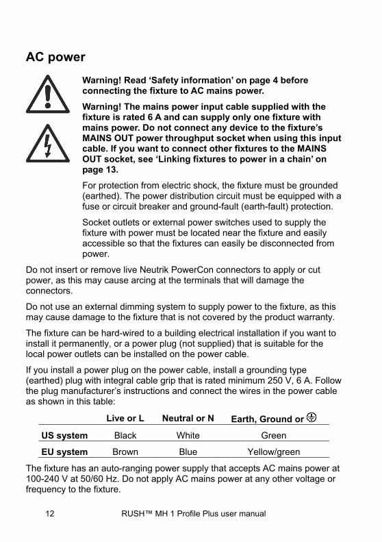
Securing with a safety cable
Secure the fixture with a safety cable (or other secondary attachment) that is approved for the weight of the fixture so that the safety cable will hold the fixture if a primary attachment fails. Loop the safety cable through the cutout in the fixture’s baseplate (arrowed in illustration on right) and around a secure anchoring point.
Martin™ can supply suitable safety cables and rigging clamps (see ‘Accessories’ on page 41).
12 RUSH™ MH 1 Profile Plus user manual
AC power
Warning! Read ‘Safety information’ on page 4 before connecting the fixture to AC mains power.
Warning! The mains power input cable supplied with the fixture is rated 6 A and can supply only one fixture with mains power. Do not connect any device to the fixture’s MAINS OUT power throughput socket when using this input cable. If you want to connect other fixtures to the MAINS OUT socket, see ‘Linking fixtures to power in a chain’ on page 13.
For protection from electric shock, the fixture must be grounded (earthed). The power distribution circuit must be equipped with a fuse or circuit breaker and ground-fault (earth-fault) protection.
Socket outlets or external power switches used to supply the fixture with power must be located near the fixture and easily accessible so that the fixtures can easily be disconnected from power.
Do not insert or remove live Neutrik PowerCon connectors to apply or cut power, as this may cause arcing at the terminals that will damage the connectors.
Do not use an external dimming system to supply power to the fixture, as this may cause damage to the fixture that is not covered by the product warranty.
The fixture can be hard-wired to a building electrical installation if you want to install it permanently, or a power plug (not supplied) that is suitable for the local power outlets can be installed on the power cable.
If you install a power plug on the power cable, install a grounding type (earthed) plug with integral cable grip that is rated minimum 250 V, 6 A. Follow the plug manufacturer’s instructions and connect the wires in the power cable as shown in this table:
Live or L Neutral or N Earth, Ground or
US system Black White Green
EU system Brown Blue Yellow/green
The fixture has an auto-ranging power supply that accepts AC mains power at 100-240 V at 50/60 Hz. Do not apply AC mains power at any other voltage or frequency to the fixture.

RUSH™ MH 1 Profile Plus user manual 13
Linking fixtures to power in a chain
If you obtain a 14 AWG / 1.5 mm2 power input cable and 14 AWG / 1.5 mm2 throughput cables from Martin™ (see ‘Accessories’ on page 41), you can relay mains power from one fixture to another by connecting fixtures to power in a linked daisy-chain, MAINS OUT throughput socket to MAINS IN input socket. Using 14 AWG or 1.5 mm2 cables from Martin™, you can link:
• Maximum four (4) RUSH MH 1 fixtures in total at 100-120 V, or
• Maximum eight (8) RUSH MH 1 fixtures in total at 200-240 V.
If you install a power plug on the 14 AWG / 1.5 mm2 power cable, install a grounding type (earthed) plug with integral cable grip that is rated minimum 250 V, 16 A.
Fixture overview
1 - Display
2 - LEDs
The fixture has two LEDs on the front of the base with the following functions:
DMX On DMX input present SOUND Flashing Sound activation
3 - Buttons
MENU
• Activate the menu mode functions, or
• Return to the previous level of the menu structure, or
• Hold to exit the menus DOWN Go down a menu branch
UP Go up a menu branch
ENTER Confirm the selected function
Press and hold the MENU button to exit the menu mode.
14 RUSH™ MH 1 Profile Plus user manual
4 - DMX XLR input/output sockets
3-pin and 5-pin XLR sockets are provided for DMX input and output (throughput).
5 - Fuse
The T 6.3 A fixture fuse is located in a fuseholder next to the power input/output connectors.
6 - Mains power input
A blue Neutrik PowerCon socket is provided to connect the fixture to AC mains power.
7 - Mains power throughput
See ‘Safety information’ on page 4. The light-grey Neutrik PowerCon socket can be used to supply power to other fixtures only if the power input cable is replaced as directed in this manual and safety limits are respected.
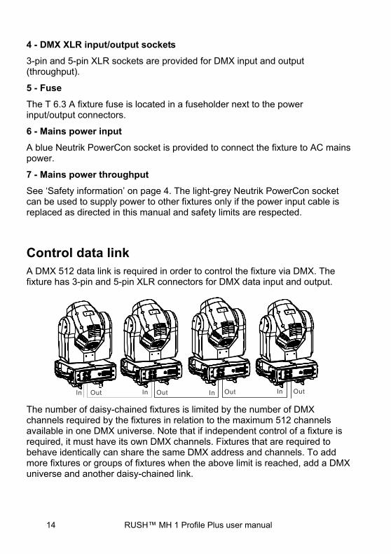
Control data link A DMX 512 data link is required in order to control the fixture via DMX. The fixture has 3-pin and 5-pin XLR connectors for DMX data input and output.
The number of daisy-chained fixtures is limited by the number of DMX channels required by the fixtures in relation to the maximum 512 channels available in one DMX universe. Note that if independent control of a fixture is required, it must have its own DMX channels. Fixtures that are required to behave identically can share the same DMX address and channels. To add more fixtures or groups of fixtures when the above limit is reached, add a DMX universe and another daisy-chained link.
RUSH™ MH 1 Profile Plus user manual 15
Tips for reliable data transmission
Use shielded twisted-pair cable designed for RS-485 devices: standard microphone cable cannot transmit control data reliably over long runs. 24 AWG cable is suitable for runs up to 300 meters (1000 ft.). Heavier gauge cable and/or an amplifier is recommended for longer runs. The pin-out on all connectors is pin 1 = shield, pin 2 = cold (-), and pin 3 = hot (+). Pins 4 and 5 in the 5-pin XLR connectors are not used in the fixture but are available for possible additional data signals as required by the DMX512-A standard. Standard pin-out is pin 4 = data 2 cold (-) and pin 5 = data 2 hot (+).
To split the link into branches, use a splitter such as the Martin 4-Channel Opto-Isolated RS-485 Splitter/Amplifier. Terminate the link by installing a DMX termination plug in the output socket of the last fixture. The termination plug, which is a male XLR plug with a 120 Ohm, 0.25 W resistor soldered between pins 2 and 3, “soaks up” the control signal so it does not reflect and cause interference. If a splitter is used, terminate each branch of the link.
Connecting the DMX data link
To connect the fixture to data:
1. Connect the DMX data output from the controller to the first fixture’s male XLR DMX input connector.
2. Connect the first fixture’s DMX output to the DMX input of the next fixture and continue connecting fixtures output to input. Terminate the last fixture on the link with a DMX termination plug.
Fixture setup This section explains the fixture settings and utilities that the user has access to via the control panel.
A complete map of the control menu structure can be found in ‘Control menus’ on page 33.
Settings are retained when the fixture is powered off.
Using the control menus
To access the control menus, press the MENU button. Navigate the menu structure using the ENTER, DOWN and UP buttons. Select any required menu option using the ENTER button. To return to the previous level in the menu structure without making a change, press the MENU button.
To exit the menus, press and hold the MENU button.
16 RUSH™ MH 1 Profile Plus user manual
DMX function settings
DMX function settings include the DMX address and a DMX value viewer.
DMX addressing The DMX address, also known as the start channel, is the first channel used to receive instructions from a DMX controller. The fixture can be controlled using signals sent by a DMX controller over 17 channels. Each DMX controlled fixture must have a DMX address set. For example, if a fixture has a DMX address of 10, then it uses channels 10, 11, 12, 13, 14, 15, 16, 17, 18, 19, 20, 21, 22, 23, 24, 25 and 26. The following fixture in the DMX chain could then be set to a DMX address of 27.
For independent control, each fixture must be assigned its own control channels. Two fixtures of the same type may share the same address, if identical behavior is desired. Address sharing can be useful for diagnostic purposes and symmetric control, particularly when combined with the inverse pan and tilt options.
The DMX address is configured using the DMX FUNCTIONS menu in the control panel.
To set the fixture’s DMX address:
1. Select DMX FUNCTIONS and press ENTER.
2. Use the UP and DOWN buttons to select DMX ADDRESS and press ENTER to confirm. The present address will blink on the display.
3. Use the UP and DOWN buttons to select a new address.
4. Once the address has been selected, press ENTER to set it (or press MENU to exit without saving any changes).
DMX viewer The DMX viewer lets you see the DMX values that the fixture is receiving on each channel. This lets you check for a correct DMX signal and correct operation.
To see the DMX values:
1. Select DMX FUNCTIONS and press ENTER.
2. Use the UP and DOWN buttons to select DMX VALUE and press ENTER.
3. Use the UP and DOWN buttons to scroll through the DMX channels and press ENTER to select a channel. The fixture will display the DMX value it is receiving on that channel.
4. Press MENU to exit the viewer.

RUSH™ MH 1 Profile Plus user manual 17
Show settings
Show settings determine the behavior of the fixture when it is disconnected from DMX and if, and how, it will run one of the onboard shows.
Offline mode Offline mode defines what the fixture will do if it loses or is not connected to a DMX signal. There are three options: M/S (enter standalone Show Mode), HOLD (do nothing), or BLACKOUT.
To set a fixture’s offline mode:
1. Select SHOW SETTINGS and press ENTER to confirm.
2. Use the DOWN and UP buttons to select OFFLINE MODE and press ENTER to confirm.
3. Use the DOWN and UP buttons to select M/S, HOLD, or BLACKOUT.
4. Once the offline mode has been selected, press ENTER to set (or press MENU to exit without saving any changes).
Show settings Show mode provides four preprogrammed shows. These are not accessible via DMX. Show mode can be combined with music trig sound activation to provide a synchronized light show.
To set a fixture’s show mode:
1. Select SHOW SETTINGS and press ENTER to confirm.
2. Use the DOWN and UP buttons to select SHOW MODE and press ENTER to confirm.
3. Use the DOWN and UP buttons to select SHOW 1, SHOW 2, SHOW 3 or SHOW 4.
4. Once the show has been selected, press ENTER to set (or press MENU to exit without saving any changes).
Setting focus for gobo wheels 1 and 2 For the shows, you can set focus for each of the two gobo wheels: 1 (rotating gobos) and 2 (fixed gobos).
To set the focus for a gobo wheel:
1. Select SHOW SETTINGS and press ENTER to confirm.
2. Use the DOWN and UP buttons to select FOCUS 1 or FOCUS 2 (corresponding to wheel 1 (rotating) or wheel 2 (fixed)) and press ENTER to confirm.
3. Use the DOWN and UP buttons to change the focus point from 0…255.

18 RUSH™ MH 1 Profile Plus user manual
4. Once the level has been selected, press ENTER to set it (or press MENU to exit without saving any changes).
Music trig sound activation The fixture has a built-in microphone that can be used to synchronize its behavior to the beat of music. When the fixture is not connected to a DMX controller, and is running one of the preprogrammed shows, it can be set to trigger scene changes (effects, color changes and movement) in synch with music.
To turn on sound activation:
1. Select SHOW SETTINGS and press ENTER to confirm.
2. Use the DOWN and UP buttons to select SOUND TRIGGER and press ENTER to confirm.
3. Use the DOWN and UP buttons to select ON (sound activation on) or OFF (sound activation off).
4. Press ENTER to set it (or press MENU to exit without saving any changes).
To adjust the sensitivity of the sound-activation microphone:
1. Select SHOW SETTINGS and press ENTER to confirm.
2. Select SOUND SENSIVITY and press ENTER to confirm.
3. Use the DOWN and UP buttons to change the microphone sensitivity from 0 …100 (low-high).
4. Once the level has been selected, press ENTER to set it (or press MENU to exit without saving any changes).
Fixture settings
Pan and/or tilt inversion The FIXTURE SETTINGS→PAN INVERSE and TILT INVERSE menus can be used to reverse the direction of pan and/or tilt. These settings are useful for symmetrical effects with multiple fixtures, or when coordinating the movement of fixtures that are floor mounted and rigged upside down.
To adjust the pan inversion settings:
1. Select FIXTURE SETTINGS and press ENTER to confirm.
2. Use the DOWN and UP buttons to select PAN INVERSE or TILT INVERSE and press ENTER to confirm.
3. Use the DOWN and UP buttons to select YES (inversion) or NO (normal).

RUSH™ MH 1 Profile Plus user manual 19
4. Press ENTER to confirm (or press MENU to exit without saving any changes).
Pan/tilt feedback By default, pan/tilt feedback is enabled. This means that if a pan or tilt position error is detected, the fixture will correct the pan/tilt position.
To deactivate, or activate this function use the FIXTURE SETTINGS→P/T FEEDBACK menu.
Iris inversion To invert the iris settings:
1. Select FIXTURE SETTINGS and press ENTER to confirm.
2. Use the DOWN and UP buttons to select IRIS INVERSE and press ENTER to confirm.
3. Use the DOWN and UP buttons to select YES (inversion) or NO (normal).
4. Press ENTER to confirm (or press MENU to exit without saving any changes).
Blackout during change or movement The fixture can be set to black out during gobo changes, color changes and/or pan and tilt movement. This feature is disabled by default.
To adjust the blackout during show playback settings:
1. Select FIXTURE SETTINGS and press ENTER to confirm.
2. Use the DOWN and UP buttons to select BL. O. P/T MOVING, BL. O. COLOR CHANGE, or BL. O: GOBO CHANGE and press ENTER to confirm.
3. Use the DOWN and UP buttons to select YES (blackout during movement or change) or NO (normal).
4. Press ENTER to confirm (or press MENU to exit without saving any changes).
Brightness calibration
You can use the brightness calibration feature to set the maximum light output level during standalone operation or to match output levels across multiple fixtures.
To set brightness calibration:
1. Power the fixture on. If matching multiple fixtures, aim them so that their projections are side-by-side.
20 RUSH™ MH 1 Profile Plus user manual
2. Select BRIGHTNESS CALI. and press ENTER.
3. Using the DOWN and UP buttons, change the value from 50 …100 to adjust the maximum light level.
4. Press ENTER to confirm (or press MENU to exit without saving any changes).
Display settings
Invert display Inverting the display is useful if the fixture is hung from a truss or from elevation. To invert the display:
1. Select DISPLAY SETTINGS and press ENTER to confirm.
2. Use the DOWN and UP buttons to select DISPLAY INVERSE and press ENTER to confirm.
3. Use the DOWN and UP buttons to select YES (invert) or NO (normal).
4. Press ENTER to confirm (or press MENU to exit without saving any changes).
Automatically turn off display backlight By default the display is lit when the power is applied to the fixture. It can be set to automatically dim if the buttons and menus have not been used for a period:
1. Select DISPLAY SETTINGS and press ENTER to confirm.
2. Use the DOWN and UP buttons to select BACKLIGHT AUTO OFF and press ENTER to confirm.
3. Use the DOWN and UP buttons to select YES (auto off) or NO (constant backlight).
4. Press ENTER to confirm (or press MENU to exit without saving any changes).
Adjust backlight brightness The brightness of the control panel display can be adjusted:
1. Select DISPLAY SETTINGS and press ENTER to confirm.
2. Use the DOWN and UP buttons to select BACKLIGHT BRIGHTNESS and press ENTER to confirm.
3. Use the DOWN and UP buttons to select a level from 1 to 10.
4. Press ENTER to confirm (or press MENU to exit without saving any changes).

RUSH™ MH 1 Profile Plus user manual 21
Hide error messages You can set whether error messages (see p. 36) are hidden or displayed:
1. Select DISPLAY SETTINGS and press ENTER to confirm.
2. Use the DOWN and UP buttons to select DISPLAY WARNING and press ENTER to confirm.
3. Use the DOWN and UP buttons to select YES (display) or NO (hide).
4. Press ENTER to confirm (or press MENU to exit without saving any changes).
Fixture test
Automatic tests of all functions or manual test of individual functions can be run from the control menus.
Auto test To perform a complete test of all of the fixture functions:
1. Select FIXTURE TEST and press ENTER to confirm.
2. Use the DOWN and UP buttons to select AUTO TEST and press ENTER to confirm. The automatic test will run.
3. Press MENU to exit.
Manual test Fixture functions can be tested or controlled manually:
1. Select FIXTURE TEST and press ENTER to confirm.
2. Use the DOWN and UP buttons to select MANUAL TEST and press ENTER to confirm.
3. Press MENU to exit.
Fixture information
Fixture operating hours counter To see how many hours the fixture has been used:
1. Select FIXTURE INFORMATION and press ENTER to confirm.
2. Use the DOWN and UP buttons to select FIXTURE USE HOUR and press ENTER to confirm. The number of hours will be shown.

22 RUSH™ MH 1 Profile Plus user manual
Service countdown counter This counter is resettable and can be used to monitor service intervals. The counter is available under the FIXTURE INFORMATION→LIGHT USE HOUR menu.
Firmware version To see what software version is installed in the fixture:
1. Select FIXTURE INFORMATION and press ENTER to confirm.
2. Use the DOWN and UP buttons to select FIRMWARE VERSION and press ENTER to confirm. The firmware version will be shown.
Reset functions or effects
The various effects—pan, tilt color, gobos, iris, focus, prism—or all effects, can be manually reset to their home positions:
1. Select RESET FUNCTIONS and press ENTER to confirm.
2. Use the DOWN and UP buttons to select the function or effect that is to be reset. Press ENTER.
3. Use the DOWN and UP buttons to select YES and press ENTER to confirm (or press MENU to exit without saving any changes).
Reset factory default settings
The fixture’s default settings can be restored using SPECIAL FUNCTIONS→FACTORY SETTINGS.
Effect home position adjustment (Offset menu)
The various effects—pan, tilt color wheels, gobo wheels, gobos, iris, focus, and prism—can lose or move out of their indexed home position. To reset any of these:
1. In the menu structure, hold the ENTER button down for approx. 3 seconds to enter the OFFSET MENU.
2. Use the DOWN and UP buttons to choose the function that needs to be adjusted. Press ENTER to select it.
3. The present indexed home position will appear blinking in the display. Use the DOWN and UP buttons to adjust the home position of the function or effect.
4. Once the correct position has been reached, press ENTER to set this (or press MENU to exit without saving any changes).

RUSH™ MH 1 Profile Plus user manual 23
Effects This section describes DMX-controllable effects that require particular explanation. See DMX protocol on page 29 for a full list of the DMX channels and values required to control the different effects.
Pan and tilt
The fixture’s moving head can be panned through 540° and tilted through 270° using coarse and fine control channels. The fixture can be set to automatically blackout during pan and tilt movement.
The fixture incorporates pan and tilt feedback, so that if a pan or tilt position error is detected, the shutter closes and the fixture resets to the correct pan & tilt position. This can be disabled if not required (see ‘Control menus’ on page 33).
Gobos
The fixture contains two gobo wheels:
Any gobo can be projected statically, or the wheels can be rotated, both clockwise and counter-clockwise. Individual gobos on wheel 1 can be rotated both clockwise and counter-clockwise, and a gobo shake function is available. The fixture can be set to automatically blackout during gobo changes.
Iris
The fixture provides an adjustable iris, allowing the diameter of the projected beam to be adjusted.
Motorized focus
The focus of gobos projected onto a surface can be adjusted.

24 RUSH™ MH 1 Profile Plus user manual
Prism
The fixture incorporates a prism than can be inserted into the beam, providing split effects. The prism can be set to an indexed position or rotated clockwise or counter-clockwise.
Strobe effects
The strobe effects provide instant open and blackout, variable speed regular and random strobe.
Electronic dimming
Overall intensity can be adjusted 0-100%.
Color wheels
The fixture incorporates two color wheels, each with seven colors plus open/white. These can be individually selected, or the wheels can be rotated at varying speeds, both clockwise and counter-clockwise. The fixture can be set to automatically blackout during color changes.

RUSH™ MH 1 Profile Plus user manual 25
Maintenance
Warning! Read ‘Safety information’ on page 4 before servicing the fixture.
Refer any service operation not described in this user manual to a qualified service technician.
Disconnect mains power before cleaning or servicing the fixture.
Service fixtures in an area where there is no risk of injury from failing parts, tools, etc.
The user may carry out the service operations described in this manual. All other service operations must be carried out by an authorized Martin™ service technician. Do not try to repair the fixture yourself, as you may create a safety risk or cause damage that is not covered by the product warranty.
Installation, on-site service and maintenance can be provided worldwide by the Martin Professional™ Global Service organization and its approved agents, giving owners access to Martin’s expertise and product knowledge in a partnership that will ensure the highest level of performance throughout the product’s lifetime. Please contact Martin™ for details.
Cleaning
Excessive dust, smoke fluid, and particle buildup degrades performance, causes overheating and will damage the fixture. Damage caused by inadequate cleaning or maintenance is not covered by the product warranty.
The cleaning of external optical lenses must be carried out periodically to optimize light output. Cleaning schedules for lighting fixtures vary greatly depending on the operating environment. It is therefore impossible to specify precise cleaning intervals for the fixture. Environmental factors that may result in a need for frequent cleaning include:
• Use of smoke or fog machines.
• High airflow rates (near air conditioning vents, for example).
• Presence of cigarette smoke.
• Airborne dust (from stage effects, building structures and fittings or the natural environment at outdoor events, for example).
If one or more of these factors is present, inspect fixtures within their first 100 hours of operation to see whether cleaning is necessary. Check again at frequent intervals. This procedure will allow you to assess cleaning
26 RUSH™ MH 1 Profile Plus user manual
requirements in your particular situation. If in doubt, consult your RUSH by Martin dealer about a suitable maintenance schedule.
Use gentle pressure only when cleaning, and work in a clean, well-lit area. Do not use any product that contains solvents or abrasives, as these can cause surface damage.
To clean the fixture:
1. Disconnect the fixture from power and allow it to cool for at least 10 minutes.
2. Vacuum or gently blow away dust and loose particles from the outside of the fixture and the air vents at the back and sides of the head and in the base with low-pressure compressed air.
3. Clean the surfaces by wiping gently with a soft, clean lint-free cloth moistened with a weak detergent solution. Do not rub glass surfaces hard: lift particles off with a soft repeated press. Dry with a soft, clean, lint-free cloth or low-pressure compressed air. Remove stuck particles with an unscented tissue or cotton swab moistened with glass cleaner or distilled water.
4. Check that the fixture is dry before reapplying power.
Replacing the primary fuse
If the fixture is completely dead, the fixture’s primary fuse F1 may have blown and it may be necessary to install a new fuse. This fuse is located in a fuseholder next to the Mains OUT socket on the connections panel. See ‘Fixture overview’ on page 13.
If you need to replace a fuse:
1. Disconnect the fixture from power and allow it to cool for at least 10 minutes.
2. Unscrew the cap of the fuseholder and remove the fuse. Replace with a fuse of the same size and rating only.
3. Reinstall the fuseholder cap before reapplying power.

RUSH™ MH 1 Profile Plus user manual 27
Gobo replacement
It is possible to replace the rotating gobos with custom gobos that match the quality and specifications of the gobos supplied with the fixture (see Gobos on page 40).
Gobo replacement must be carried out by a qualified professional technician only.
Optical components are fragile and are exposed to high temperatures. Wear cotton gloves while handling them and keep them perfectly clean to reduce the risk of heat damage. Do not contaminate them with grease or oil (from your fingers for example). Handle and store them with care.
To replace a gobo:
1. Disconnect the fixture from power and allow it to cool for at least 10 minutes.
2. See below. Remove the fixture head covers using a Phillips screwdriver and find the side of the head that gives access to the gobo wheel.
3. The rotating gobos sit in goboholders that slot into clips in the rotating gobo wheel. Find the gobo you want to replace. See below. Pull its goboholder away from the gobo wheel slightly, then lift the goboholder out of its clip in the wheel.
28 RUSH™ MH 1 Profile Plus user manual
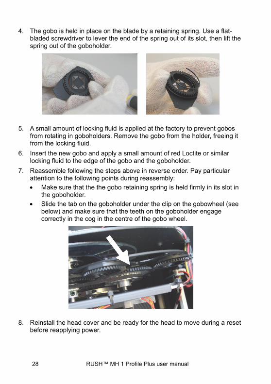
4. The gobo is held in place on the blade by a retaining spring. Use a flat-bladed screwdriver to lever the end of the spring out of its slot, then lift the spring out of the goboholder.
5. A small amount of locking fluid is applied at the factory to prevent gobos from rotating in goboholders. Remove the gobo from the holder, freeing it from the locking fluid.
6. Insert the new gobo and apply a small amount of red Loctite or similar locking fluid to the edge of the gobo and the goboholder.
7. Reassemble following the steps above in reverse order. Pay particular attention to the following points during reassembly:
• Make sure that the the gobo retaining spring is held firmly in its slot in the goboholder.
• Slide the tab on the goboholder under the clip on the gobowheel (see below) and make sure that the teeth on the goboholder engage correctly in the cog in the centre of the gobo wheel.
8. Reinstall the head cover and be ready for the head to move during a reset before reapplying power.

RUSH™ MH 1 Profile Plus user manual 29
DMX protocol
Chan. Value Function
1 0-255 Pan 0°-540° 2 0-255 Pan (fine control) 3 0-255 Tilt 0°-270° 4 0-255 Tilt (fine control) 5 0-254 Pan/tilt speed, fast- slow
255 Pan/tilt speed, fast 6 0-255 Dimmer 0-100% 7 Strobe
0-7 Off 8-15 Open
16-131 Strobe, slow-fast 132-139 Open 140-181 Fast close, slow open 182-189 Open 190-231 Slow close, fast open 232-239 Open 240-247 Random strobe 248-255 Open
8 Color wheel 1 0-7 Color 1 – Open 8-15 Color 2 – Light Blue 16-23 Color 3 – Green 24-31 Color 4 – Orange 32-39 Color 5 – Yellow 40-47 Color 6 – Magenta 48-55 Color 7 – Dark blue 56-63 Color 8 – Red
64-127 Indexing 128-189 Clockwise, fast-slow 190-193 Stop 194-255 Counter-clockwise, slow-fast
9 Color wheel 2 0-7 Color 1 – Open 8-15 Color 2 – Pink 16-23 Color 3 – CTO 3200 K 24-31 Color 4 – Purple 32-39 Color 5 – Yellow

30 RUSH™ MH 1 Profile Plus user manual
Chan. Value Function
40-47 Color 6 – Green 48-55 Color 7 – CTO 5600 K 56-63 Color 8 – Blue
64-127 Indexing 128-189 Clockwise, fast-slow 190-193 Stop 194-255 Counter-clockwise, slow-fast
10 Gobo wheel 1 (rotating gobos)
0-7 Open 8-15 Gobo 1 16-23 Gobo 2 24-31 Gobo 3 32-39 Gobo 4 40-47 Gobo 5 48-55 Gobo 6 56-63 Gobo 7 64-73 Gobo 1 shake 74-82 Gobo 2 shake 83-91 Gobo 3 shake
92-100 Gobo 4 shake 101-109 Gobo 5 shake 110-118 Gobo 6 shake 119-127 Gobo 7 shake 128-189 Wheel rotation, clockwise, fast-slow 190-193 Stop 194-255 Wheel rotation, counter clockwise, slow-fast
11 Gobo rotation (wheel 1) 0-127 Indexed position, 0°-360°
128-189 Clockwise rotation, fast-slow 190-193 Stop 194-255 Counter-clockwise rotation, slow-fast

RUSH™ MH 1 Profile Plus user manual 31
Chan. Value Function
12 Gobo wheel 2 (fixed gobos)
0-7 Open 8-14 Gobo 1 15-21 Gobo 2 22-28 Gobo 3 29-35 Gobo 4 36-42 Gobo 5 43-49 Gobo 6 50-56 Gobo 7 57-63 Gobo 8 64-71 Gobo 1 shake 72-79 Gobo 2 shake 80-87 Gobo 3 shake 88-95 Gobo 4 shake
96-103 Gobo 5 shake 104-111 Gobo 6 shake 112-119 Gobo 7 shake 120-127 Gobo 8 shake 128-189 Wheel rotation, counter clockwise, fast-slow 190-193 Stop 194-255 Wheel rotation, clockwise, slow-fast
13 Prism 0-127 No effect
128-255 Prism effect 14 Prism rotation
0-127 Indexed position 0°-360° 128-189 Clockwise rotation, fast-slow 190-193 Stop 194-255 Counter-clockwise rotation, slow-fast
15 0-255 Iris, maximum-minimum 16 0-255 Focus, close-distant 17 Settings and fixture control
0-69 No function 70-79 Blackout during pan & tilt
32 RUSH™ MH 1 Profile Plus user manual
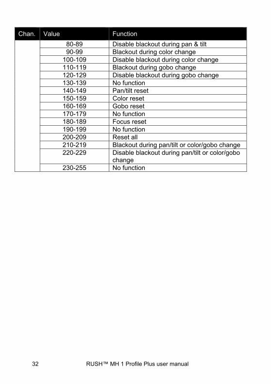
Chan. Value Function
80-89 Disable blackout during pan & tilt 90-99 Blackout during color change
100-109 Disable blackout during color change 110-119 Blackout during gobo change 120-129 Disable blackout during gobo change 130-139 No function 140-149 Pan/tilt reset 150-159 Color reset 160-169 Gobo reset 170-179 No function 180-189 Focus reset 190-199 No function 200-209 Reset all 210-219 Blackout during pan/tilt or color/gobo change 220-229 Disable blackout during pan/tilt or color/gobo
change 230-255 No function

RUSH™ MH 1 Profile Plus user manual 33
Control menus To access the control menus, press the MENU button. Use the UP and DOWN buttons to navigate the menus. Select any required menu option using the ENTER button. For more information, see ‘Fixture setup’ on page 15.
Default fixture settings are shown in bold.
Menu Sub-menu Setting/value Explanation
DMX Functions
DMX Address 1–512 Fixture DMX address setting
Mode 17 channel
View DMX Value View values received on DMX channels
Show settings
Offline Mode
M/S When no DMX signal, go to Show Mode
Hold When no DMX signal, hold current effect
Blackout When no DMX signal, black out
Show Mode
Show 1 Pre-programmed show 1
Show 2 Pre-programmed show 2
Show 3 Pre-programmed show 3
Show 4 Pre-programmed show 4
Focus 1 0-255 Focus setting for gobo wheel 1 (rotating gobos)
Focus 2 0-255 Focus setting for gobo wheel 2 (fixed gobos)
Sound Trigger Off Sound activation off On Sound activation on
Sound Sensitivity 0-100 Sound activation microphone sensitivity (low-high)
34 RUSH™ MH 1 Profile Plus user manual
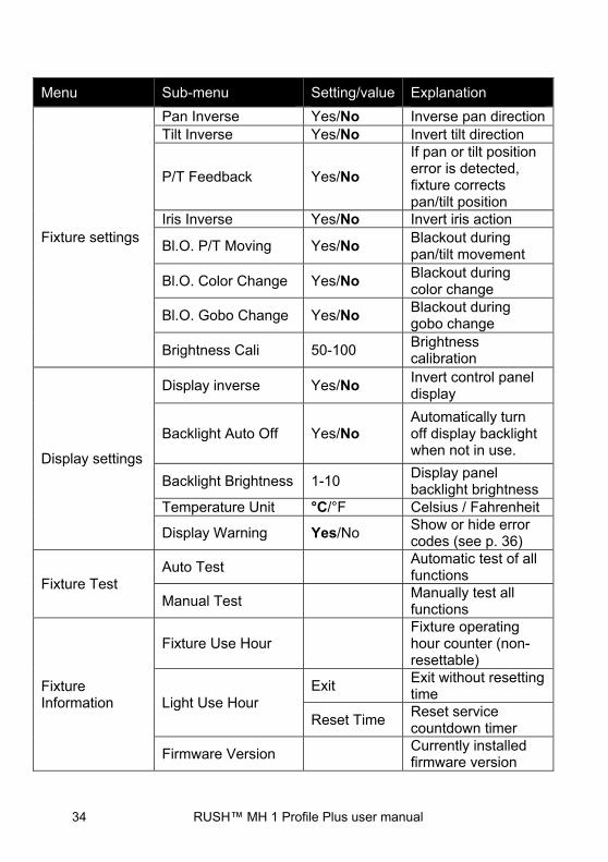
Menu Sub-menu Setting/value Explanation
Fixture settings
Pan Inverse Yes/No Inverse pan direction Tilt Inverse Yes/No Invert tilt direction
P/T Feedback Yes/No
If pan or tilt position error is detected, fixture corrects pan/tilt position
Iris Inverse Yes/No Invert iris action
Bl.O. P/T Moving Yes/No Blackout during pan/tilt movement
Bl.O. Color Change Yes/No Blackout during color change
Bl.O. Gobo Change Yes/No Blackout during gobo change
Brightness Cali 50-100 Brightness calibration
Display settings
Display inverse Yes/No Invert control panel display
Backlight Auto Off Yes/No Automatically turn off display backlight when not in use.
Backlight Brightness 1-10 Display panel backlight brightness
Temperature Unit °C/°F Celsius / Fahrenheit
Display Warning Yes/No Show or hide error codes (see p. 36)
Fixture Test Auto Test
Automatic test of all functions
Manual Test Manually test all functions
Fixture Information
Fixture Use Hour Fixture operating hour counter (non-resettable)
Light Use Hour Exit
Exit without resetting time
Reset Time Reset service countdown timer
Firmware Version Currently installed firmware version

RUSH™ MH 1 Profile Plus user manual 35
Menu Sub-menu Setting/value Explanation
Reset Functions
Pan & Tilt Yes/No
Reset effects to home position
Color Yes/No Gobo Yes/No Prism Yes/No Iris Yes/No Focus Yes/No All Yes/No
Special Functions
Factory Settings Yes/No Return all settings to factory defaults
Offset menu
The Offset menu is used to adjust the home position of the various effects.
To access the Offset menu, press the MENU button to enter the menu structure and then press and hold the ENTER button for three seconds.
Menu Sub-menu Setting Explanation
Offset
Pan -128...127 Tilt -128...127
Color 1 -128...127
Color 2 -128...127
Gobo 1 -128...127 Wheel with rotating gobos
R Gobo 1 -128...127 Rotating gobos
Gobo 2 -128...127 Wheel with fixed gobos
Iris 0-255
Prism 0-255
R prism -128...127
Focus 0-255
36 RUSH™ MH 1 Profile Plus user manual
Error messages
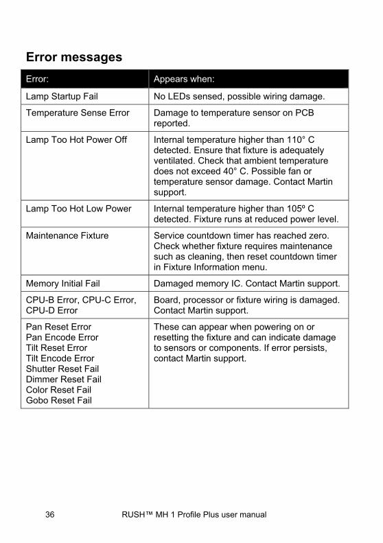
Error: Appears when:
Lamp Startup Fail No LEDs sensed, possible wiring damage.
Temperature Sense Error Damage to temperature sensor on PCB reported.
Lamp Too Hot Power Off Internal temperature higher than 110° C detected. Ensure that fixture is adequately ventilated. Check that ambient temperature does not exceed 40° C. Possible fan or temperature sensor damage. Contact Martin support.
Lamp Too Hot Low Power Internal temperature higher than 105º C detected. Fixture runs at reduced power level.
Maintenance Fixture Service countdown timer has reached zero. Check whether fixture requires maintenance such as cleaning, then reset countdown timer in Fixture Information menu.
Memory Initial Fail Damaged memory IC. Contact Martin support.
CPU-B Error, CPU-C Error, CPU-D Error
Board, processor or fixture wiring is damaged. Contact Martin support.
Pan Reset Error Pan Encode Error Tilt Reset Error Tilt Encode Error Shutter Reset Fail Dimmer Reset Fail Color Reset Fail Gobo Reset Fail
These can appear when powering on or resetting the fixture and can indicate damage to sensors or components. If error persists, contact Martin support.
RUSH™ MH 1 Profile Plus user manual 37
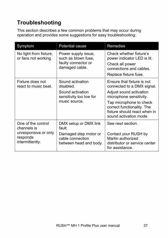
Troubleshooting This section describes a few common problems that may occur during operation and provides some suggestions for easy troubleshooting:
Symptom Potential cause Remedies
No light from fixture, or fans not working.
Power supply issue, such as blown fuse, faulty connector or damaged cable.
Check whether fixture’s power indicator LED is lit.
Check all power connections and cables.
Replace fixture fuse.
Fixture does not react to music beat.
Sound activation disabled.
Sound activation sensitivity too low for music source.
Ensure that fixture is not connected to a DMX signal.
Adjust sound activation microphone sensitivity.
Tap microphone to check correct functionality. The fixture should react when in sound activation mode.
One of the control channels is unresponsive or only responds intermittently.
DMX setup or DMX link fault.
Damaged step motor or cable connection between head and body.
See next section.
Contact your RUSH by Martin authorized distributor or service center for assistance.
38 RUSH™ MH 1 Profile Plus user manual
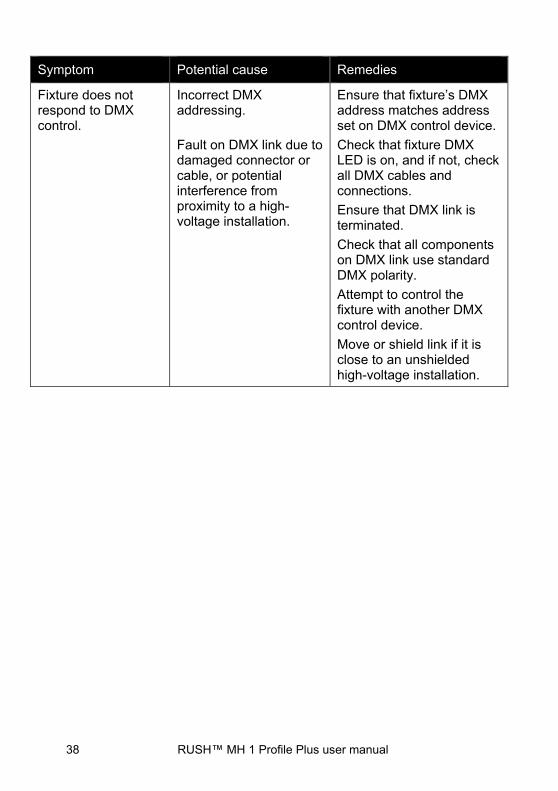
Symptom Potential cause Remedies
Fixture does not respond to DMX control.
Incorrect DMX addressing.
Fault on DMX link due to damaged connector or cable, or potential interference from proximity to a high-voltage installation.
Ensure that fixture’s DMX address matches address set on DMX control device.
Check that fixture DMX LED is on, and if not, check all DMX cables and connections.
Ensure that DMX link is terminated.
Check that all components on DMX link use standard DMX polarity.
Attempt to control the fixture with another DMX control device.
Move or shield link if it is close to an unshielded high-voltage installation.

RUSH™ MH 1 Profile Plus user manual 39
Specifications Physical
Dimensions (LxWxH).............. 418 x 328 x 588 mm (16.5 x 12.9 x 23.1 in.) Weight ................................................................................ 18 kg (39.7 lbs.)
Dynamic Effects Color wheel 1 ............................................ 7 colors plus open, rotation with variable direction and speed Color wheel 2 ........................... 7 colors (incl. 1 x UV, 2 x CTC) plus open, rotation with variable direction and speed Rotating gobo wheel............................. 7 gobos plus open, wheel rotation, gobo indexing, rotation and shake Static gobo wheel ................. 8 gobos plus open, wheel rotation and shake Electronic 'shutter' effect ............. Strobe effect, pulse effects, instant open and blackout Prism .................... Indexing and rotation with variable direction and speed Iris ................................................................................................. Motorized Focus ............................................................................................ Motorized Electronic dimming ........................... 0 - 100%, four dimming curve options Pan .................................................. 540°, coarse & fine control and speed Tilt .................................................... 270°, coarse & fine control and speed
40 RUSH™ MH 1 Profile Plus user manual
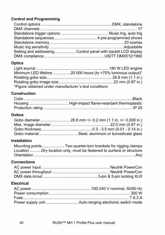
Control and Programming Control options ................................................................. DMX, standalone DMX channels ......................................................................................... 17 Standalone trigger options ............................................ Music trig, auto trig Standalone sequences ....................................... 4 pre-programmed shows Standalone memory .................................................................... 20 scenes Music trig sensitivity .................................................................... Adjustable Setting and addressing .................... Control panel with backlit LCD display DMX compliance ....................................................... USITT DMX512/1990
Optics Light source ................................................................... 180 W LED engine Minimum LED lifetime ................20 000 hours (to >70% luminous output)* Rotating gobo size ............................................................ 26.8 mm (1.1 in.) Rotating gobo image size .................................................. 22 mm (0.87 in.) *Figure obtained under manufacturer´s test conditions
Construction Color .................................................................................................... Black Housing .................................... High-impact flame-retardant thermoplastic Protection rating .................................................................................. IP 20
Gobos Gobo diameter ........................... 26.8 mm +/- 0.2 mm (1.1 in. +/- 0.008 in.) Max. image diameter ...................................................... 22.0 mm (0.87 in.) Gobo thickness ............................................... 0.3 - 3.5 mm (0.01 - 0.14 in.) Gobo material ....................................Steel, aluminum or borosilicate glass
Installation Mounting points .................... Two quarter-turn brackets for rigging clamps Location ........... Dry location only, must be fastened to surface or structure Orientation ............................................................................................. Any
Connections AC power input ............................................................... Neutrik PowerCon AC power throughput ..................................................... Neutrik PowerCon DMX data in/out ................................................... 3-pin & 5-pin locking XLR
Electrical AC power ....................................................... 100-240 V nominal, 50/60 Hz Power consumption ........................................................................... 300 W Fuse .................................................................................................. T 6.3 A Power supply unit .............................. Auto-ranging electronic switch mode

RUSH™ MH 1 Profile Plus user manual 41
Typical Power and Current 110 V, 60 Hz ......................................................... 2.63 A, 274 W, PF 0.942 230 V, 50 Hz ......................................................... 1.34 A, 268 W, PF 0.870 Measurements made at nominal voltage with all LEDs at full intensity. Allow for a deviation of +/- 10%.
Thermal Cooling .................................................. Forced air, temperature-controlled Maximum ambient temperature (Ta max.) ............................ 40° C (104° F) Minimum ambient temperature (Ta min) .................................... 0°C (32° F) Total heat dissipation* ............................................................ 1010 BTU/hr. *Calculated, +/- 10%, at full intensity, full white
Approvals
EU safety .................. EN 60598-2-17 (EN 60598-1), EN 62471, EN 62493 EU EMC ........................................... EN 55015, EN 55103-1, EN 55103-2, .................................................... EN 61000-3-2, EN 61000-3-3, EN 61547 US Safety ....................................................................................... UL 1573 US EMC ..................................................................... FCC Part 15 Class A Australia/NZ .......................................................................... C-TICK N4241
Included Items Power cable, 6 A, 18 AWG, 0.75 mm2, UL- listed, H05VV-F, 1.5 m, without mains plug Two omega-type clamp attachment brackets with quarter-turn fasteners
Accessories
Cables, 16 A, for connection to power in chains Power input cable, 14 AWG, SJT, 1.5 mm2, H05VV-F, with PowerCon input connector, 3 m (9.8 ft.) ....................... P/N 11541508 Power relay cable, 14 AWG, SJT, 1.5 mm2, H05VV-F, with PowerCon connectors, 1.4 m (4.6 ft.) ........................... P/N 11541509 Power relay cable, 14 AWG, SJT, 1.5 mm2, H05VV-F, with PowerCon connectors, 2.25 m (7.4 ft.) ......................... P/N 11541510 Power relay cable, 14 AWG, SJT, 1.5 mm2, H05VV-F, with PowerCon connectors, 3.25 m (10.7 ft.) ....................... P/N 11541511
Power connectors Neutrik PowerCon NAC3FCA power input connector, cable mount, blue ........................... P/N 05342804

42 RUSH™ MH 1 Profile Plus user manual
Neutrik PowerCon NAC3FCB power output connector, cable mount, light grey ................. P/N 05342805
Installation hardware Half-coupler clamp ............................................................... P/N 91602005 G-clamp (vertical hanging suspension only) ........................ P/N 91602003 Quick-trigger clamp (vertical hanging suspension only) ...... P/N 91602007 Safety wire, safe working load 50 kg .................................... P/N 91604003
Related Items RUSH Software Uploader 1™ .............................................. P/N 91611399
Ordering Information RUSH MH 1 Profile Plus™ in cardboard box ....................... P/N 90280050
Specifications are subject to change without notice. For the latest product specifications, see www.martin.com
Disposing of this product RUSH by Martin™ products are supplied in compliance with Directive 2012/19/EC of the European Parliament and of the Council of the European Union on WEEE (Waste Electrical and Electronic Equipment), where applicable. Help preserve the environment! Ensure that this product is recycled at the end of its life. Your supplier can give details of local arrangements for the disposal of RUSH by Martin products.
Photobiological Safety Warning
The label shown below is displayed on this product. If it becomes difficult or impossible to read, it must be replaced using the illustration below to reproduce a new label sized 45 x 18 mm, in black on a yellow background.
RISK GROUP 2
CAUTION. Possibly hazardous optical radiation emitted from this product.
Do not stare at operating lamp. May be harmful to the eyes.