mh case study application pack - solar … case study application pack 3 accreditation application...
TRANSCRIPT


MH CASE STUDY APPLICATION PACK 2
Introduction ____________________________________________________________
A case study is a representation of your best work, so please pay particular attention to the quality of your installation:
Are you using best practice methods?
Have you included the right photographs, and are they clear?
Please follow these 10 steps to provide the required information: 1. Fill out the application form 2. Attach a copy of your electrical license (not contractor’s license) if required 3. Attach a copy of your current public liability insurance certificate 4. Attach a photo for your ID card 5. Attach a fully completed wiring diagram showing the installation date 6. Attach the system performance estimate and energy resource assessment 7. Attach the installation and commissioning report 8. Attach plans for the MH turbine and hydraulic system 9. Attach system photographs (see examples below) 10. Complete the final application checklist
Note: failure to provide any of the above information will result in long processing delays as we away the missing details.

MH CASE STUDY APPLICATION PACK 3
Accreditation Application (Please ensure all entries are legible)
___________________________________________________________
Name: .............................................................................................................................................
Business Name: ..............................................................................................................................
Address: ..........................................................................................................................................
State: ................... Postcode: ...................
Work phone: ................................. Work fax: ................................. Mobile: .................................
Email: ..............................................................................................................................
1. Accreditation Upgrade I hereby apply for Upgrade of Full Accreditation. Accreditation type (please tick at least one):
□ Design and Install of MH system
Licensed Electrician No: ………………………………… (legible photocopy attached)
Note: Upgrade to full accreditation is required within three months of provisional award date. Extensions up to a maximum of three months may be available on application. 2. Payment (refer to attached Clean Energy Council Accreditation fees and charges)
□ My cheque is attached (payable to Clean Energy Council) Amount $ ...................
□ Payment by credit card (surcharges will apply): □ Amex □ MasterCard □ Visa
Card number: ............../............./............../.............. Expiry Date: ................ Amount $ ............. Name on card: ......................................................... Signature: .................................................... The accreditation fee will be refunded (less a processing charge) if the application is unsuccessful. If your accreditation expires prior to this application, you must apply for an extension in advance. 3. Insurance (please attach copy of your Certificate of Currency)

MH CASE STUDY APPLICATION PACK 4
Current public liability insurance is held with:................................................................................... Policy number: ……………………………………....... Policy value: $ …………………….. 4. Declaration (Confirm each item by ticking the checkbox, then complete and sign the declaration) I represent and warrant that:
□ All information contained in and attached to this form is correct and not misleading by
inclusion or omission.
□ I have read the Clean Energy Council Terms and Conditions (attached) and the Clean Energy
Council Code of Conduct (attached) and agree to be bound by those Terms and Conditions and the Code of Conduct upon signature of this form.
□ I understand that acceptance of my application is at the discretion of the Clean Energy
Council and I agree to abide by any rule the Clean Energy Council may make with respect to Accreditation. Application signed: ........................................................................................ Date: ............................... Please return application to: Clean Energy Council Level 15, 222 Exhibition Street Melbourne VIC 3000 Phone: 03 9929 4141 Email: [email protected] Your name, address and contact details will be published by the Clean Energy Council on its website and sent to the state agencies for the purpose of identifying you as an Accredited Installer of renewable energy systems. For further information about our use of your personal information and your right of access to it, please contact [email protected].
MH CASE STUDY APPLICATION PACK 5
Instructions The case study submission can only be made from a provisionally accredited person or fully accredited person seeking points as part of the CPD program.
If you are applying for micro hydro accreditation you must be the person who undertook the installation (you cannot sub-contract to others). Therefore your name shall be the one appearing on all relevant documentation including testing and commissioning Sheets.
The installation must have taken place during your period of accreditation. Work that was carried out prior to accreditation being granted will not be accepted.
Important:
Any electrical work involving components of up to 48VAC and 120VDC must be carried out by a competent practitioner.
All other electrical work must be carried out by a licensed electrician.
The applicant must be the commissioning installer for all MHT related components and all ELV- related components and aspects of the system.
All photographs, design information, testing and commissioning sheets and any other evidence must be from the same installation. Multiple installation pictures will render the case study void and a new case study will be required.
Please note: The Clean Energy Council has a 5 MB limit on incoming emails. You may need to resize your images if you are submitting them via email.
Case study assessment ratings
Competent: An applicant will be deemed competent when the assessor is satisfied that there is sufficient evidence that the installation has been conducted to all current and relevant standards and guidelines and that supporting evidence has been sighted as evidence of this compliance.
Not yet Competent: An applicant will be deemed not yet competent when the assessor is not satisfied that there is sufficient evidence that the installation has been conducted to all current and relevant standards and guidelines and that insufficient supporting evidence has been sighted as evidence of this compliance.
Failed: An applicant will be deemed failed/rejected in the following circumstances:
The applicant has repeatedly failed to submit the required information to the Clean
MH CASE STUDY APPLICATION PACK 6
Energy Council’s accreditation administration department.
The applicant has not submitted the correct information to the technical assessor within the allocated time. The assessor will only request this information once, and failure to provide the correct technical information will result in the application being rejected. A fail result will require the applicant to make a new submission and additional charges will apply.
The Assessor deems that the evidence provided shows an MHT installation that may be mechanically or electrically unsafe and may cause physical harm to people or property.
The applicant has submitted a false electrical license or is not licensed to carry out the work.
The applicant has not met the minimal training standard / completed the necessary training units as required to make the application.
The assessor deems that the MHT installation is in clear breach of AS/NZS 3000 wiring rules.
A fail result will require the applicant to make a new submission and additional charges will apply.
MH CASE STUDY APPLICATION PACK 7
Supporting documents ____________________________________________________________ D-02 Electrical License
Please submit a clear copy (both front & back sides) of your current electrical workers license.
D-03 Insurance Certificate
Please submit a clear copy of your current Public Liability Insurance certificate (minimum $5 million insurance cover).
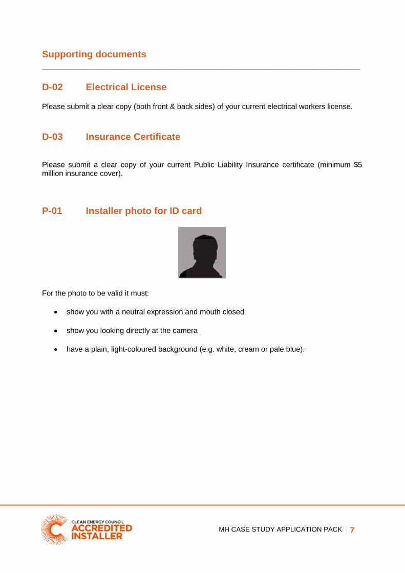
P-01 Installer photo for ID card
For the photo to be valid it must:
show you with a neutral expression and mouth closed
show you looking directly at the camera
have a plain, light-coloured background (e.g. white, cream or pale blue).

MH CASE STUDY APPLICATION PACK 8
D-01 Wiring diagram
Please provide a wiring diagram showing all electrical and electronic components of the MH system and associated standalone power supply, including:
1. MHT: make, model and capacity
2. Battery charge controller: make and model
3. Inverter: make, model, type and capacity
4. Battery: configuration, number, Ah and type of cells
5. Any other generation/charging sources: brief description, capacity
6. All isolators/fuses/circuit breakers: make, model and V and I ratings
7. All earthing and protection components, including earth-stake
8. Cables: AC or DC, length, size and type
9. For DC circuits: maximum design operating voltage drop (as V and %)
10. Dump loads: type, capacity
11. Any ELV load circuits and DC switchboard
12. Any other key elements of the system
13. Designer and installer name and signature
14. Electrician name and signature
15. Installation date and commissioning date
You may use the template line diagram provided on the next page.

Cable Length: ______ Size: ________________
Type: _______________
DC Max ____ %
Voltage Drop: ____ Volts
Cable Length: ______ Size: ________________
Type: _______________
DC Max ____ %
Voltage Drop: ____ Volts
Cable AC or DC: ______
Length: ________________
Size: __________________
Type: _________________
DC Max ____ %
Voltage Drop: ____ Volts
Other Cable Length: ____ To: _________ From: _________
Size: _______________________
Type: ______________________
DC Max _______ %
Voltage Drop: _______ Volts
Cable Length: ______ Size: ________________
Type: _______________
DC Max ____ %
Voltage Drop: ____ Volts
Customer Name: Installation Address:
Designer Name: Accred No:
Installer Name: Accred No: Signature:
Electrician Name: License No: Signature:
Installation
Date*:
LOGO
Micro hydro turbine Make: ______________________
Model: _____________________
Capacity: ____________________
Battery Charge Controller Make: ______________________
Model: _____________________
Capacity: ____________________
Inverter Make: ______________________
Model: ______________________
Type: _______________________
Capacity: ____________________
Battery Configuration: _____________
# of Cells: _________________
Ah of Cells: _______________
Type: ____________________
Other Charging Source Description: ___________
_________________________
Capacity: _________________
ELV Load Circuits
and DC Switchboard Ratings of switches and
components: ____________
________________________
________________________
________________________
________________________
Commissioning
Date:
Earthing/Protection Earth stake details: ________
________________________
Protection components: ____
________________________
________________________
________________________
Dump Load AC or DC: __ Type: __________ ________
Capacity: ________________
Isolators/Fuses/Circuit breakers Make: ____________ Model: _______________
Voltage Rating: ______ Current rating: ________
Make: ____________ Model: _______________
Voltage Rating: ______ Current rating: ________
Make: ____________ Model: _______________
Voltage Rating: ______ Current rating: ________
Make: ____________ Model: _______________
Voltage Rating: ______ Current rating: ________
Make: ____________ Model: _______________
Voltage Rating: ______ Current rating: ________

GC CASE STUDY APPLICATION PACK 10
D-02 Installation and commissioning report For items requiring description, referring to specific pages of the supplied manufacturer’s documentation is acceptable.
Installation details
Address of installation:
Customer name:
Micro hydro turbine (MHT) details
Make and model:
MHT type (e.g. Francis): Rated flow rate (range): m2/s
Rated output: W Rated head (range): m
Rated voltage: V
Generator monitoring/protection:
Turbine monitoring/protection:
Controller system:
Governing system:
Cooling system:
Lubrication system:
Micro hydro system hydraulic design
Static head: MHT to intake (min): m Penstock length: m
Static head: MHT to high water level (max):
m Tailrace length (note if enclosed or open):
m
Static head: MHT to outlet (min): m Reservoir capacity: m2
Range of total static head: m Max volumetric flow rate: m2/s
Range of net operating head: m
Pipe type/ID (e.g. high-pressure black poly/XX mm):
Water level or flow regulation:
Inlet valve type and position:
Max. closure rate for inlet valve at max. flow rate (full turns per sec):
Pressure release valve:
Battery
Battery type: Number and voltage of cells:
Ah capacity at max discharge: Redundancy/back up (days):
Max. discharge rate: Other charge sources?
Max. charge rate:
Commissioning tests
Watering up test Low speed test
Phase and continuity checks Rated speed test
Controller tests Emergency shutdown tests
Normal operation observed? Follow-up tests
Compliance with relevant standards

GC CASE STUDY APPLICATION PACK 11
Complies with AS/NZS 4509.2: Design Guidelines
Complies with AS/NZS 3000: Wiring Rules
Complies with AS/NZS 4509.1: SPS Safety and Installation
Complies with AS 4086: Secondary batteries for use with SPS installation and
maintenance
Complies with AS/NZS 5033: Installation of photovoltaic (PV) arrays
Complies with AS 2676: Guide to installation and maintenance of secondary batteries in
buildings
Complies with AS 3011: Electrical installations – secondary batteries installed in buildings
(LV batteries)
Complies with AS/NZS 3010: Electrical installations – generating sets
Information provided to the customer. The installer has:
Informed the customer of permissions or approvals required prior to installation
Provided the customer with details of the energy resource assessment and informed the
customer that MHT output is impossible to predict with certainty at most locations due to variability of rainfall
Provided the customer with a detailed inspection and maintenance schedule
Provided the customer with all supporting manufacturer’s documentation
Provided the customer with a stock of spare parts and consumables
Provided the customer with engineering certificates (where required)
Warranty details
Installation warranty:
Component warranties (complete for turbine and other major components)
Component Warranty Importer (if not locally manufactured)
Turbine
Installer details
Installer name:
Contact details:
Commissioning date:
Other commissioning reports/case study packs (for CEC purposes only)

GC CASE STUDY APPLICATION PACK 12
Installer declaration The installer confirms that any relevant building, civil and other engineering standards and all environmental, planning-related and other provisions and permissions have been met.
The installer declares that all installed support structures, mounting frames and fixing equipment have been installed in compliance with applicable building codes, regulations and standards.
In addition, all fittings and equipment are ‘fit for purpose’ and rated for use within the environment in which they are installed.
Details of the warranties on all equipment has been provided to the customer
Signed ................................................................ (Installer) Date......................
Customer Declaration I, _______________________________ have received all relevant warranties and documentation pertaining to the safe operation and performance of this system.
Signed ................................................................ (Customer) Date........................

GC CASE STUDY APPLICATION PACK 13
D-03 System Performance Estimate and Energy Resource Assessment
Under CEC design guidelines, the designer must be able to:
Estimate the gross energy available to the standalone MHT system
Estimate the net energy yield provided by the system (after any system, battery or other losses)
Estimate any seasonal variation in energy resource
Identify what portion of local energy demand will be met by the MHT system
Identify the most suitable source(s) for local energy demand not met by the MHT system These calculations should be made using methods consistent with best practice and relevant standards. There may be commercial tools available to assist in calculating energy yield. At a minimum, you must provide:
1. Evidence that the MHT voltage, current and other specifications are matched to the battery, charger and inverter specifications, and other components where relevant
2. Expected net annual energy yield (in kWh) for this system, with workings
3. Average daily performance estimate (in kWh) for the best month of MH generation, noting possible annual variance.
4. Average daily performance estimate (in kWh) for the worst month of MH generation, noting possible annual variance.
5. Estimated number of months per year at or near full capacity of MH generation, noting possible annual variance.
6. Estimated number of months per year at or near zero MH generation, noting possible annual variance.
7. Estimated number of months per year at partial MH generation, noting possible annual variance.
8. The source of estimated flow data, and/or appropriate workings.
9. Description of other energy sources where the MH is not expected to provide all local energy needs.
The number of days of redundancy built into the battery system
Manufacturer’s graphs or tables indicating rated output under different levels of head and flow.

GC CASE STUDY APPLICATION PACK 14
Notes:

GC CASE STUDY APPLICATION PACK 15
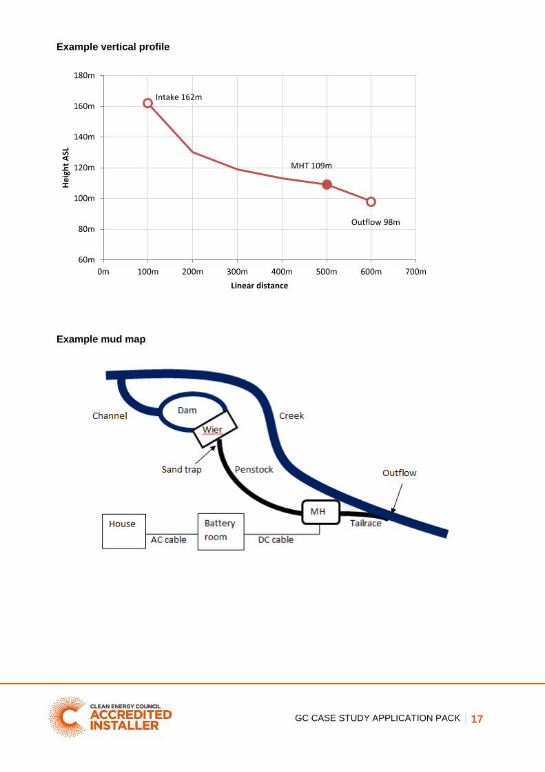
D-04 Topographic or Cadastral Maps D-05 Vertical & Horizontal Cartesian diagram D-06 A Mud- Map of the MH Layout MHT and hydraulic system plans This case study must include:
1. Topographic or cadastral map/s of the MH system and environs
2. An accurate vertical and horizontal (Cartesian) layout diagram of system
3. A mud map of the MHT and other components
Plans/diagrams should indicate:
a. Elevation ASL contours (at 10 m resolution or better)
b. Waterways (natural and constructed)
c. Location and spot height (to nearest metre ASL) of all hydraulic system components, including turbine, channel, reservoir, fish pass, weir, intake, penstock and tailrace.
d. Electrical and electronic components including cable runs
e. SPS/battery/generator room housing
f. Buildings and other loads supplied by the SPS
The example plans/diagrams on the following pages show the minimum details required.

GC CASE STUDY APPLICATION PACK 16
Example topographical map
GC CASE STUDY APPLICATION PACK 17
Example vertical profile
Example mud map
Intake 162m
MHT 109m
Outflow 98m
60m
80m
100m
120m
140m
160m
180m
0m 100m 200m 300m 400m 500m 600m 700m
He
igh
t A
SL
Linear distance

GC CASE STUDY APPLICATION PACK 18
Checklist of photographs required Please supply photographs of the following parts of your installation. We recommend supplying three photos of each element listed to ensure proper assessment.
Note: the Clean Energy Council has a 5 MB limit on incoming emails. You may need to resize your images if you are submitting them via email.
Pic # Description Supplied?
P-01 Hydro turbine in immediate environment
P-02 Hydro turbine close up
P-03 Turbine mounting pad/footings
P-04 Turbine hydraulic connections
P-05 Dam and weir (from all sides)
P-06 All penstock and tailrace fittings and valves
P-07 Inlet and filtration system
P-08 Turbine shutdown switch
P-09 Wall penetration – turbine cable entry point
P-10 DC cable ID / protection and reticulation
P-11 Turbine wiring, including all terminals
P-12 Lightning/earthing protection
P-13 Inverter and isolators – broad view
P-14 Main battery isolator
P-15 Battery bank
P-16 DC switchboard
P-17 Shutdown procedure label in place
P-18 Battery warning labels 1 (please check standard)
P-19 Battery warning label 2 (please check standard)
P-20 MH open circuit voltage & short circuit current
GC CASE STUDY APPLICATION PACK 19
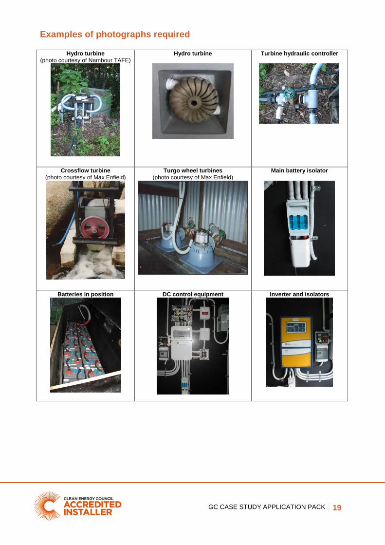
Examples of photographs required
Hydro turbine
(photo courtesy of Nambour TAFE)
Hydro turbine
Turbine hydraulic controller
Crossflow turbine
(photo courtesy of Max Enfield)
Turgo wheel turbines
(photo courtesy of Max Enfield)
Main battery isolator
Batteries in position DC control equipment Inverter and isolators

GC CASE STUDY APPLICATION PACK 20
Examples of photographs required (continued)
Cabling and reticulation Battery room Current shunts installed
Dam and weir
(photo courtesy of Max Enfield)
Control fittings
(photo courtesy of Max Enfield)
Pipework/reticulation
(photo courtesy of Max Enfield)
Labelled battery box AC and DC switchboards with main battery isolator
Shutdown procedure

GC CASE STUDY APPLICATION PACK 21
Final checklist
Please check your application against this checklist before submitting.
Completed application form attached
Copy of electrical licence attached (if required)
Evidence of public liability insurance provided
Completed wiring diagram attached
Installation and commissioning report completed and signed by customer
System performance estimate and energy resource assessment completed
System plans/diagrams completed and attached
All photographs attached and photograph checklist completed