mhi fm 11-21 manuals/1961 us army vietnam war... · mhi copy 3 department 0 fm 11-21 f the army...
TRANSCRIPT

MHICopy 3
DEPARTMENT 0
FM 11-21F THE ARMY FIELD MANUAL
TACTICALSIGNAL COMMUNICATIONSYSTEMS, ARMY, CORPS,
AND DIVISION
HEADQUARTERS, DEPARTMENT OF THE ARMY
NOVEMBERAGO 2522B
1961
WWW.SURVIVALEBOOKS.COM

FM 11-21
]AELt MANUAL) HEADQUARTERS,DEPARTMENT OF THE ARMY
No. 11-21 J WASHINGTON 25, D. C., 21 November 1961
TACTICAL SIGNAL COMMUNICATION SYSTEMS,ARMY, CORPS, AND DIVISION
Paragraph PageCHAPTER 1. INTRODUCTION
Purpose -..... .1 3Scope -........ 2 3References .-..------ 3 3
2. SIGNAL COMMUNICATION SYSTEMSSection I. General
Basic considerations ------------------------ 4 4Signal communication requirements - ............ 5 4Signal centers ---------------- 6 5Signal communication .-..- 7 5Transmission media .-....- 8 7
II. Field army area communication systemGeneral ------- ---------------------- 9 8Field army area signal communication troop units__ 10 9Radio nets -...... .11 9Messenger service- .. ................ 12 10
III. Corps signal communication systemGeneral ---------------------------------- 13 10Trunking systems ...-.............. 14 11Signal centers ---. IS.-- ---------- 15 11Utilization of field army area communication system 16 11Radio nets -............. 17 13Messenger service -...... 18 13
IV. D)ivision area communication systemGeneral -..------------ 19 13Signal centers ------------------------------- 20 13Lateral communication ...- . - 21 14Infantry division -. ..--- 22 14Armored and mechanized division -. .......- 23 16Airborne division .................------- 24 20
CHAPTER 3. SIGNAL COMIMUNICATION PLANNINGGeneral ------------ 25 22Basic considerations- ...--.---. .....-------- 26 22
Planning procedures - .- --- ------- 27 23Planning guidance - . . ------ 28 23Analysis of communication requirements .- . .... 29 26General plan .---------------------------- 30 28Assignments of tasks .-..------- 31 28I)etailed system design -.-.-.- ------ 32 31Orders and records --------------------------- 33 33
TAGO 2522B--November I
WWW.SURVIVALEBOOKS.COM

Paragraph Page
CHAPTER 4. APPLIED SYSTEMS ENGINEERINGGeneral ---------------- 34 34Systems and circuit engineering ------------------ 35 34Telephone traffic engineering ..-.. ............... 36 36Teletypewriter traffic engineering ..-.. .......... 37 37Manually switched teletypewriter system- ... .38 37Tape relay system ---------------------------- 39 38Sole-user teletypewriter service ----------------- 40 40Reserve facilities -.... 41 40
5. SIGNAL COMMUNICATION CONTROLGeneral -. ..-------- 42 41Field army organization for signal communication
control -... ............................ 43 41Applications of control .-....................... 44 43Signal center and unit communication designators_ 45 44System designation -............. 46 47Circuit numbering system- .. . ... .47 48Signal locator and routing service- -.. - -- 48 49Records and reports ----. .........--- 49 52Electronic accounting machine applications ..- 50 59Telephone directory service -.. ...... 51 59
6. SIGNAL CENTER DISPLACEMENTDisplacement of field army signal centers --------- 52 63Displacement of corps signal centers ------------ 53 64I)isplacement of division signal centers ---------- 54 64
APPENDIX I. REFERENCES .---- --------------- --. 68II. GUIDE FOR PLANNING TACTICAL SIGNAL
COMMUNICATION SYSTEMS ------------- 70
AGO 2522B2
WWW.SURVIVALEBOOKS.COM

CHAPTER 1
INTRODUCTION
1. PurposeThis manual is prepared as a guide for personnel who must
plan, engineer, control, and supervise the installation, operation,and maintenance of field army, corps, or division signal communi-cation systems.
2. Scopea. This manual contains information on signal communication
systems, requirement planning, applied system engineering, signalcommunication control, and signal center displacement for fieldarmy, corps, and division.
b. The material contained herein is applicable without modifica-tion to both nuclear and nonnuclear warfare.
c. The diagrams included in this manual are sample illustrationsonly.
d. Users of this manual are encouraged to submit recommendedchanges or comments to improve the manual. Comments shouldbe keyed to the specific page, paragraph, and line of the text inwhich change is recommended. Reasons should be provided foreach comment to insure understanding and complete evaluation.Comments should be forwarded direct to Commandant, USASignal School, Fort Monmouth, N.J.
3. ReferencesThe publications listed in appendix I provide additional infor-
mation on subjects related to the material contained in this manual.Their use will assist the reader to better understand and employthe material presented herein.
AGO 2522B 3
WWW.SURVIVALEBOOKS.COM

CHAPTER 2
SIGNAL COMMUNICATION SYSTEMS
Section I. GENERAL
4. Basic Considerationsa. Tactical commanders continually stress dispersion, mobility,
and flexibility in the employment of tactical units. However,dispersion, mobility, and flexibility can be realized only if signalcommunication systems are designed to support these operationalconcepts and provide the commander with the necessary capa-bility for control. The signal communication system must be ableto absorb damage from nuclear attack without complete disrup-tion of signal communications. It must be flexible and capable ofquick reaction to changes in operational plans and task organiza-tion. It must be able to support all command requirements, as wellas certain sole-user circuit requirements of higher headquarters.It must provide, as an integral feature, communication securityto the maximum extent possible, consistent with operational con-siderations.
b. The communication system, of a field army, is composed ofthe field army area communication system, the communicationsystem organic to subordinate corps, the area communicationsystem of the divisions, and other communication facilities ofunits integral to the field army.
5. Signal Communication RequirementsThe tactical communication system is designed to:a. Provide continuous communication service to widely dis-
persed units and installations utilizing security equipment whererequired.
b. Meet changes in task organization and, at the same time,facilitate relocation of units, command posts (CP's) and installa-tions.
c. Provide patching facilities to permit the electrical reroutingand physical relocation of circuits with a minimum of systemchanges.
d. Be able to operate at extended distances; have a high ca-pacity potential to meet demands placed upon it, and be composedof building-block type units so that changing requirements can bemet by adding or removing unit elements.
e. Provide continuity of communication service during non-nuclear or nuclear warfare.
AGO 2522B4
WWW.SURVIVALEBOOKS.COM

-f. Provide a common-user system over which sole-user circuitscan be provided on the basis of precedence or volume of traffic asapproved by the commander.
g. Be sufficiently mobile to support the elements of a rapidlymoving tactical force.
6. Signal CentersA signal center is a grouping of signal communication facilities
that are installed, operated, and maintained by U.S. Army SignalCorps units. Each signal center normally provides a communica-tions center and messenger service, telephone and teletypewriterswitching, circuit testing and rerouting facility, radio/wire inte-gration stations, radio, radio relay and carrier transmission andreceipt media. Additional facilities, such as facsimile and auto-matic data processing, may be provided when authorized. Thetwo types of signal centers are command signal centers and areasignal centers.
a. Command Signal Centers. Command signal centers providesignal facilities for specific command headquarters and to desig-nated units located in their immediate vicinity.
b. Area Signal Centers. Area signal centers provide signalfacilities within designated geographical areas, and serve all unitswithin the area requiring such support. Area signal centers re-main under the operational control of the signal officer of the com-mand providing the area center. Internal communication of sup-ported units remains the responsibility of those units.
7. Signal Communicationa. Telephone. The telephone system for tactical units is de-
signed primarily as a common-user system. Telephone require-ments are largely dictated by the density of military populationand missions of the units or activities. A great number of callsoriginating in the division area will go directly to activities andunits outside of the division area. Calls from division to armyunits are likely to cover great distances and, to avoid delays andtransmission losses, they must be routed through the minimumnumber of switching points.
b. Teletypewriter. Teletypewriter is the principal electricalfacility used to transmit message traffic between signal centers.In addition, many units and activities have organic teletypewritersets operated by their own personnel. Examples of teletypewriteruse are-
(1) Normally, teletypewriter sets are connected to teletype-writer switchboards, in a teletypewriter system similarto the telephone system. Some teletypewriter circuits
5AGO 2522B
WWW.SURVIVALEBOOKS.COM

may be patched around the switching centers to providedirect communication.
(2) Signal centers utilize multichannel teletypewriter car-rier systems and teletypewriter switchboards to providethe circuit needs for teletypewriter service.
(3) Teletypewriter is also used with single-channel mobileradio sets. This type of facility retains the advantages ofteletypewriter and provides the additional advantages ofmobility and flexibility of service. Radio teletypewriter(RATT) equipment is used in command and administra-tive radio nets, emergency communication nets, specialpurpose nets such as those used for the coordination ofair-ground operations, weather information, flight plans,and aircraft identification.
c. Communications Center. Communications centers, providedat all signal centers, are established by the signal unit that installsand operates the signal center. Each communications centernormally includes a message center section, a cryptographic sec-tion, and transmitting and receiving section.
d. Facsimile. Facsimile is a very effective method for thetransmission of graphic data, such as charts, maps, diagrams,and photographs. The signal officer provides facsimile servicebetween installations as required. For example, facsimile servicemay be required between the echelons of army headquarters, be-tween army headquarters and corps headquarters, and betweenaviation installations. Circuits for facsimile service should beprovided on a sole-user basis when the volume or precedence oftraffic justifies such action.
e. Data Processing. Automatic data processing (ADP) (com-mand control information systems) may be used for many func-tions; for example, fire control, target analysis, intelligence, per-sonnel, supply, and similar operations. ADP facilities and equip-ment are to be managed to the maximum extent practical as anintegral part of the signal communication system. Use of ADPin the field army requires signal communication channels for thetransmission of data. Data may be transferred by data trans-ceivers operating at teletypewriter speed, or data may be trans-ferred directly between computers at high speeds over wide bandcommunication circuits. In the former case, teletypewriter qualitycircuits are sufficient. In the case of data transfer between com-puters, high quality wide band circuits equivalent to many voicecircuits are required. Data cards or tape may be transmittedby messenger.
f. Cryptographic. Cryptographic equipment is used to providea degree of communication security. The ultimate objective is the
6 AGO 2522B
WWW.SURVIVALEBOOKS.COM

transmission of all message traffic, whether classified or unclassi-fied, over circuits protected by on line encryption equipment.
(1) Crypto-equipment and associated material is used toprovide security of communications. Information per-taining to communications security is contained in FM32-5.
(2) Cryptographic equipment can be used either off or online depending upon the particular needs of the user and.the type of equipment provided.
(a) Off line equipment is normally not associated withcommunication equipment.
(b) On line equipment is associated with specific com-munications means and provides encryption/decryp-tion simultaneously with transmission/reception. Online equipment should be used to the maximum extentpossible to insure speed of service consistent withsecurity requirements.
(3) Cryptologistic support in any given theater of opera-tions is provided by Command Issuing Offices, Field ArmyIssuing Offices, and Distribution Authorities. WithinCONUS, cryptologistic support is provided by COMSECRegional Issuing Offices and Distribution Authorities.
8. Transmission MediaSignal communication facilities are interconnected by a trans-
mission medium to form a communication system. The transmis-sion medium is provided by one or a combination of the following:
a. Wire. Wire is a major medium of communications because ofits reliability and relative security and freedom from interferenceas compared with radio. Its employment is limited in rapidlymoving tactical situations because of the installation time required.Field cable used with carrier equipment is the principal type ofwire system used in the field army.
b. Radio. Radio is a major medium of communications.(1) High frequency (HF) and very high frequency (VHF)
radio sets can be installed in vehicles to provide mobility.(2) High-power radio sets are used for long range com-
munication, emergency communication, communicationin air-ground operations, and to establish command andadministrative radio nets.
(3) Low-power short range radio sets are used at the lowercommand levels.
(4) Radio/wire integration stations, provided at designatedsignal centers, give considerable flexibility to the use ofradio in the field army area.
AGO 2622B 7
WWW.SURVIVALEBOOKS.COM

c. Radio Relay. Radio relay is a major medium of transmissionbecause of its great mobility, flexibility, and relative ease of in-stallation. Although radio relay uses frequencies in the very highfrequency (VHF), ultra high frequency (UHF) or super highfrequency (SHF) range with transmission characteristics whichmay limit the range to line-of sight, intermediate repeaters canextend the range to several hundred miles. Radio repeaters maybe eliminated in certain applicable cases through use of tropo-spheric scatter equipment. Radio relay is always used in conjunc-tion with carrier or multiplexing equipment providing manychannels of communication and achieving more efficient use ofthe radio frequency spectrum available.
d. Messenger Service. A properly organized messenger serviceis one of the most effective means of communications for trans-mitting bulk materials, such as orders, requisitions, packages,data cards, and maps. Signal messenger service can be used todeliver documents classified up to and including secret.
Section II. FIELD ARMY AREA COMMUNICATION SYSTEM
9. Generala. The field army area communication system is composed of
signal centers interconnected by trunk circuits under centralizedcontrol. Each signal center provides all signal facilities requiredto support the units and activities within its assigned area of re-sponsibility. Each signal center of the field army area communica-tion system is interconnected with at least two others to providedivided and alternate routing and permit distribution of the trafficload. Command signal centers may be directly interconnectedwhen availability of facilities, distance, and other factors permit.
b. The field army area communication system varies in con-figuration, size, and composition according to the following fac-tors:
(1) Mission, composition, and organization of the field army.(2) Location and disposition of the supported forces, units,
and installations.(3) Characteristics of the area of operation.(4) Enemy capabilities.(5) Availability of indigenous facilities.(6) Number of signal centers comprising the system.(7) Communication-electronics requirements of the sup-
ported forces, units, and installations.c. The field army area communication system is interconnected
through its area and command signal centers with the head-quarters of corps, the area communication system of the divisions,
8 AGO 2522B
WWW.SURVIVALEBOOKS.COM

and other major subordinate commands comprising the field army.Army area signal centers may be physically located within thedivision area. In the rear of the field army area, signal facilitiesoperated by the Signal Long Lines Command are located to inter-connect with field army signal centers and to provide the fieldarmy access to the theater army communication system. Figure 1illustrates the interconnection of various signal centers by multi-channel communication systems.
d. The field army area communication system is designedprimarily as a common-user system. When communication re-quirements cannot be satisfied by the use of common-user facili-ties because of the need for immediate reaction, or when the volumeof justifiable traffic from one given point to another is great,sole-user circuits may be provided. The requirement for sole-userfacilities must be properly justified in terms of urgency or volumeof traffic and carry the approval of the field army commander.This approval should be indicated in the signal portion of the fieldarmy SOP for recurring and established requirements. Authorityto approve sole-user circuits should be delegated to the ArmySignal Officer for temporary or unforeseen requirements.
10. Field Army Area Signal Communication Troop UnitsThe field army area communication system is installed, oper-
ated, and maintained by the combat area signal group (with itssignal combat area battalions and a signal cable constructionbattalion), an army signal battalion, a signal communicationscenter operations company, and such other units as required.The number and types of battalions may be tailored to meet thetactical communications requirements of the field army. Thesignal combat area battalions install, operate, and maintain thearmy signal centers and the interconnecting trunks (FM 11-86).The signal cable construction battalion installs field cable fortrunk circuits and field cable for extension purposes as required(FM 11-15). The army signal battalion provides the commandsignal centers which serve the echelons of field army headquarters.It also provides the personnel and equipment to install and main-tain a main and alternate. field army tactical operations center(FATOC) (FM 11-95). The signal communications center oper-ations company provides internal communications for operationalheadquarters within the field army as required.
11. Radio NetsFrequency modulation (FM) and amplitude modulation (AM)
radio nets form an integral part of the field area communicationsystem. Details on the composition of field army radio nets andtheir use are covered in FM 11-95.
AGO 2522B 9
WWW.SURVIVALEBOOKS.COM
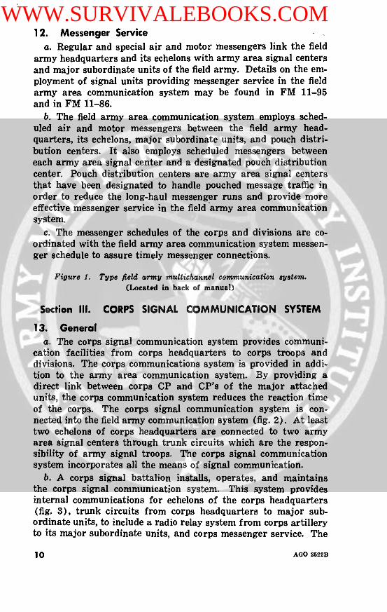
12. Messenger Servicea. Regular and special air and motor messengers link the field
army headquarters and its echelons with army area signal centersand major subordinate units of the field army. Details on the em-ployment of signal units providing messenger service in the fieldarmy area communication system may be found in FM 11-95and in FM 11-86.
b. The field army area communication system employs sched-uled air and motor messengers between the field army head-quarters, its echelons, major subordinate units, and pouch distri-bution centers. It also employs scheduled messengers betweeneach army area signal center and a designated pouch distributioncenter. Pouch distribution centers are army area signal centersthat have been designated to handle pouched message traffic inorder to reduce the long-haul messenger runs and provide moreeffective messenger service in the field army area communicationsystem.
c. The messenger schedules of the corps and divisions are co-ordinated with the field army area communication system messen-ger schedule to assure timely messenger connections.
Figure 1. Type field army multichannel communication system.(Located in back of manual)
Section III. CORPS SIGNAL COMMUNICATION SYSTEM
13. Generala. The corps signal communication system provides communi-
cation facilities from corps headquarters to corps troops anddivisions. The corps communications system is provided in addi-tion to the army area communication system. By providing adirect link between corps CP and CP's of the major attachedunits, the corps communication system reduces the reaction timeof the corps. The corps signal communication system is con-nected into the field army communication system (fig. 2). At leasttwo echelons of corps headquarters are connected to two armyarea signal centers through trunk circuits which are the respon-sibility of army signal troops. The corps signal communicationsystem incorporates all the means of signal communication.
b. A corps signal battalion installs, operates, and maintainsthe corps signal communication system. This system providesinternal communications for echelons of the corps headquarters(fig. 3), trunk circuits from corps headquarters to major sub-ordinate units, to include a radio relay system from corps artilleryto its major subordinate units, and corps messenger service. The
10 AGO 2622B
WWW.SURVIVALEBOOKS.COM

corps signal officer is normally delegated operational control of thecorps signal battalion by the corps commander.
c. The corps signal battalion consists of a headquarters andheadquarters company, a command operations company, and afield operations company. For details on the organization andemployment of the corps signal battalion, refer to FM 11-92.
14. Trunking Systemsa. Multichannel communication trunks of the corps signal com-
munication system extend between echelons of corps headquarters,and from corps headquarters direct to major subordinate head-quarters, attached divisions, and other combat and special units(fig. 3). When corps rear is established, the corps communicationtrunks are extended to that echelon. However, this may beaccomplished through the field army area communication system.Priority is placed upon use of radio relay for corps trunks; how-ever, field cable is installed when practicable.
b. Multichannel communication facilities of the corps signalbattalion are provided to establish trunks between corps artilleryheadquarters and attached field artillery groups. Trunks alsoare established between corps artillery and each division artillery(fig. 3).
Figure 2. Corps communication system integrated with the field army com-munication system, schematic diagram.
(Located in back of manual)
15. Signal CentersSignal communication is provided for corps headquarters
through signal centers established at each echelon of the command.The principal command signal centers in the corps communicationsystem are at corps main, corps advance, and corps rear. Trunksconnecting with the field army area communication system are theresponsibility of army signal troops.
16. Utilization of Field Army Area Communication SystemCorps headquarters and field army headquarters are connected
by circuits routed through multichannel systems interconnectingarmy area signal centers and by point-to-point facilities. Thelatter may be high-frequency radio circuits, radio relay systems,and/or field cable. Divisions use the field army system for com-munication direct to field army units and installations on admin-istrative and logistical matters in which corps headquarters is notinvolved. The corps signal communication system, integrated withthe field army area communication system, provides the degree of
AGO 2522B 11
WWW.SURVIVALEBOOKS.COM

I
V
90
.2
0
v
L
AGO 25221s12
WWW.SURVIVALEBOOKS.COM

flexibility required of signal communication on the nuclear battle-field.
17. Radio NetsCorps radio communication facilities are provided at each
echelon of corps headquarters, and at subordinate corps unit head-quarters as required. Stations are operated in both the field armyand corps nets. In general, corps organizations provide their ownradio station for operation in corps and army nets. Corps pro-vides radio teletypewriter stations for entry by corps artilleryand special units into certain corps nets. The nets establishedand those in which corps stations operate are discussed in detailin FM 11-92. The radio nets of the corps form an integral partof the corps communication system.
18. Messenger ServiceCorps operates a signal messenger service providing scheduled
and special air and motor messenger runs. Scheduled messengerruns are established to provide the most frequent and economicalservice practicable. Corps signal messenger service also preparesand handles pouched message distribution through the field armyarea messenger system.
Section IV. DIVISION AREA COMMUNICATION SYSTEM
19. Generala. The division area communication system is installed, oper-
ated, maintained, and controlled by personnel of the divisionsignal battalion. The system is composed of forward area signalcenters and command signal centers interconnected through multi-and single-channel circuits, radio/wire integration stations, andsignal messenger service.
b. The division signal officer (DSO), assisted by his staff, plansand directs the installation and operation of the division area com-munication system. The battalion S3, under the direction of theDSO, establishes and operates a division systems control and signalinformation center which supervises circuit routing, circuit as-signment, emergency rerouting, and designation of control termi-nals for the system.
20. Signal Centersa. General. Signal centers are interconnected by multichannel
radio relay and, when the situation permits, by field cable. Com-mand signal centers are located at each echelon of division head-quarters and at the division support command CP. The system is
AGO 2522B 13
WWW.SURVIVALEBOOKS.COM

extended to other users by field cable, field wire, or by FM radio/wire integration links.
b. Trunks. Trunks of the division area communication systemprovide a means of communication from the echelons of divisionheadquarters to immediate subordinate elements, and betweensubordinate elements. They provide circuits for other division ele-ments as required, to supplement the organic communications ofthese elements.
c. Circuits. The division area communication system is com-prised mainly of common-user circuits. To meet special require-ments, sole-user circuits may be allocated to an organizationfor full-time use to provide point-to-point communication.
d. Signal Center Interconnections.(1) Command and forward area signal centers are .inter-
connected by trunk circuits. Each center is linked to atleast two other centers; this provides alternate routingbetween centers to cope with emergencies, to facilitatetraffic handling, to distribute the traffic load, and to re-duce telephone switching.
(2) The division area communication system is integratedwith the corps and the field army communication systems.Corps signal troops provide an interconnecting link be-tween the corps and the division area communicationsystems, usually terminating at the division main signalcenter. The field army provides an interconnecting linkbetween the field army and division area communicationsystems, usually terminating at the division support com-mand signal center.
21. Lateral CommunicationNormally, lateral communications are provided between divi-
sions. It is the responsibility of the division on the left to providecommunication to the division on the right unless directed other-wise by a common commander. Lateral circuits between divisionsmay be provided through the field army area communication sys-tem to augment or supplement facilities provided by the divisions.
22. Infantry Divisiona. General. A type division area communication system is
illustrated in figure 4. Type multichannel networks are shown infigures 5, 6, and 7. Radio nets form an integral part of the divisionarea communication system.
(1) FM and AM radio normally are used as an initial meansof communications, particularly when other means,such as wire or radio relay, are unavailable or unsuit-
14 AGO 2522B
WWW.SURVIVALEBOOKS.COM

able. As other means become available, the use of radiomay be curtailed and, when practicable, radio stationsare placed on standby or listening silence as dictatedby the situation.
(2) Although radio nets are designated functionally (com-mand, intelligence, warning), traffic and other considera-tions will frequently dictate that the nets be combinedand used for more than one type of traffic.
b. Signal Centers. The infantry division signal battalion hasthe capability to install, operate, and maintain the followingsignal centers:
(1) Division main.(2) Division alternate.(3) Division support command.(4) Division rear.(5) Three forward signal centers.
c. Additional Installations. If required, additional installationswill be established, such as-
(1) Switching facilities.(2) Own terminals on radio relay systems to adjacent di-
visions.(3) Facilities for a division fire support coordination center
(FSCC).d. Messenger Service.
(1) Scheduled and special air messenger runs are the normalmethod of the messenger support provided the division.Air messengers are supplemented by ground motor mes-sengers. The aviation battalion is responsible for pro-viding aircraft and aviators for both scheduled andspecial air messenger service. Messenger service isnormally provided from higher unit headquarters tolower headquarters. However, special messengers maybe dispatched from lower to higher unit headquarterswhen the situation warrants.
(2) Messengers operating in the division messenger servicemake deliveries directly to the signal centers and toheadquarters message centers of the brigades and toother major divisional elements. The forward areasignal centers serve only as messenger pickup and de-livery points for the divisional unit elements in theirrespective areas. The division area ground messengerservice is normally provided by messengers operatingin pairs for optimum security. If increased messengerservice is required, messengers may have to operate
AGO 2522B 15
WWW.SURVIVALEBOOKS.COM

separately. In this case, an additional person should be,assigned to each messenger as a security guard.
23. Armored and Mechanical DivisionsThe armored and mechanized divisions employ an area com-
munication system similar to that employed by the infantry di-
SUPPLEMENTED BY:lIGH FREQUENCY AM RADIO.
FM RADIO MESSENGER SERVICE, AND RAOiO/WIREINTEGRATION,
TO A 1ARMY AREA LEGENDSIENAL LEGEN 8D
CEGNT' 2 12-C.ANNEL RADIO $ SPIRAL FOUR CABLERELAY SYSTEMS CARRIER SYSTEM
2T CHANN.EL RADIORELAY SYSTEM FIELD WIRECIRCUITS
FM 11-50-5
Figure 4. Type division area Communication system.
AGO 2522B
WWW.SURVIVALEBOOKS.COM

vision. The armored and mechanized divisions depend to a greaterdegree on internal radio communication than does the infantrydivision.
TO AJA DIVIF REQUIRED
TO CORPS
s - .TO AJA DIVIF REQUIRED
XX
RE.A
TTO ARMY AREASIGNAL CENTER
LEGEND:t 2-2 CHANNEL RADIORELAY SYSTEMS
¶ 12 CHANNEL RAOIORELAY SYSTEM
f SPIRAL FOUR CABLE
TO ARMY AREASIGNAL CENTER
UTILIZATION OF RA
UNIT
COMO OP CODIV MAINOIV ALTNDIV SPTMFO COMM COtWO COMO SIG PLATFWO AREA SIGCEN PLAT
0DI RELAY SETS AN/MRC-69
COMMITTED RESERVE
022
5
$
5
4
6
NOTE:2 EA AN/MRC-54 AND AN/MRC-69NO a HO COUNCOMMITTED.
FMII-50-C
Figure 5. Type multichannel communication network for the offense.
AGO 2522B 17
WWW.SURVIVALEBOOKS.COM
SIG
TO AJA DIV
IF REQUIRED
TO CORPS
/ AN/MRC-54
IN
TOAJA DIV
iF REQUIRED
LEGEND:12 CHANNELRADIDO RELAYSYSTEM
REAR
SS ICEN
rITO ARMYAREA SIG CEN
TO ARMYAREA 51E CEN
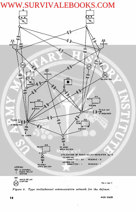
UTILIZATION OF RADIOAN/MRC-69
COMMITTED- 25AN/MRC-54
COMMITTED- I
RELAY/REPEATER SETS
RESERVE - 8
RESERVE- I
RADIO RELAYSTATION
FM 11-50
Figure 6. Type multichannel communication network for the defense.
AGO 2522B18
WWW.SURVIVALEBOOKS.COM

xx
TO BE INSTALLEODBY USE OF ACFTOR MTR VEH E
I
I
I
I
NOTE
?
AN/MRC-69:COMMITTEO-15
AN/MRC-54:COMMtTTED-O
DIRECTIONOF
MOVEMENT
RESERVE -18
RESERVE - 2
LEGEND:12 CHANNEL RADIORELAY SYSTEM.
--- PROPOSED INSTALLATION,
NOTE:SIGNAL CENTERS CONSIST OF RADIO RELAYTERMINAL AND PATCHING FACILITIES. OTHERFACILITIES ARE CARRIED IN COLUMN FORCOMMITMENT AS REQUIREO. FMII-5O-D
Figure 7. Type multichannel communication network for the advance tocontact.
AGO 2622B
XX
I
I
I
I
I
I
I
�� IIIIIIIII
�Lr ,
19
WWW.SURVIVALEBOOKS.COM

24. Airborne Divisiona. General. The airborne division employs a division area com-
munication system. Tactical radio nets established in the air-borne division augment the communication facilities of the divi-sion multichannel communication system. The nets provide flexiblecommunication for the initial assault phase of an airborne opera-tion, for rapid displacement of major command posts, and forperiods during which personal voice communication between com-manders is desired. Radio sets within division headquarters anddivision units are primarily for internal organizational commu-nication and for communication between major division units.Radio equipment is also provided for communication between divi-sion and higher headquarters. A type airborne division multi-channel communication system is illustrated in figure 8.
b. Signal Centers. The airborne signal battalion has thecapability to install, operate, and maintain the following signalcenters:
(1) Division headquarters.(2) Three area signal centers.(3) Division alternate signal center.(4) Division support command signal center.
c. Additional Installations. If required, additional installationswill be established, such as-facilities for an FSCC.
d. Radio Nets. Detailed information concerning the internaland external radio nets in which the airborne division operates iscontained in FM 11-57. The radio nets of the airborne division,as do those of the infantry and armored divisions, form an integralpart of the airborne division area communication system.
e. Messenger Service Division Headquarters. Messenger serv-ice in the signal battalion is limited to two 2-man messengerteams with vehicles. The division aviation battalion is responsiblefor providing aircraft and aviators for both scheduled and specialair messenger service.
AGO 2522B20
WWW.SURVIVALEBOOKS.COM

LEGEND'
4 CHANNELT RADtO RELAY
SPIRAL-FOURCABLE
INTEGRATION IFMI
> FIELD WIRE
FM I 1-57-2
Figure 8. Type airborne division multichannel communication network.
AGO 2522B 21
WWW.SURVIVALEBOOKS.COM

CHAPTER 3
SIGNAL COMMUNICATION PLANNING
25. GeneralSignal communication plans are developed for each tactical
plan. The planning cycle for the signal planner follows the sametested sequence used by the tactical planner. This chapter pro-vides broad guidance for the signal planner at army, corps, anddivision level. It applies, regardless of the nature of the situa-tion. In general, two types of situations are considered; first,situations involving the installation of complete initial systems;and second, situations requiring the modification or expansion ofexisting systems.
26. Basic ConsiderationsThe process of communication planning consists primarily of
determining how capabilities can best be utilized to meet require-ments. Selection of a course of action is based on analysis andcomparison of possible solutions in the light of certain basic con-siderations. These considerations are mission, time, troops, enemycapabilities, logistics, and characteristics of the area of opera-tions.
a. Mission. The signal mission can be determined only throughan analysis of the mission of the command. Fulfillment of thesignal mission thus determined then becomes the overriding con-sideration.
b. Time. Under time, the communication planner considers howlong he has for planning, the length of time available for installa-tion, and the probable duration of.the operation.
c. Troops. All aspects of the troop structure of the commandmust be considered. The number, type, mission, dispositions,and organic communication capability of all units must be knownif requirements are to be accurately determined. Knowledge ofthe status of signal troops is essential to the understanding ofcapabilities.
d. Enemy Capabilities. The signal communication planner con-siders primarily the ability of the enemy to interfere with or dis-rupt communications and the vulnerability of his radio communi-cations to intercept and subsequent intelligence exploitation. Inthis respect, the planner must consider the requirement for com-munications security.
e. Logistics. The elements of logistics which most affect com-munication planning are supply, maintenance, and transportation.
22 AGO 2522B
WWW.SURVIVALEBOOKS.COM

f. Characteristics of the Area of Operation. These character-istics include weather, terrain, size, and shape of the area andexisting signal communication facilities.
27. Planning ProceduresSuccessful signal communication planning depends upon the
accomplishment of a series of specific procedures. These includethe issuance of planning guidance, analysis of communication re-quirements, design of general plan to meet requirements, assign-ment of tasks, detailed system design, publication of orders, andmaintenance of records.
a. Planning Guidance. This includes criteria for circuit alloca-tions, priorities, transmission, and traffic engineering data; pro-vision for reserve facilities for expansion or replacement pur-poses; and limitations on use of organic means or indigenousfacilities. Much of the detail of this guidance is placed in thestanding operating procedure (SOP) of the command and thusrequires only review and updating for application to a specificoperation.
b. Analysis of Communication Requirements. The degree towhich requirements are analyzed will depend on the time availablefor planning and the information known to the planner. Re-quirements must be converted to allocations during the planningprocess.
c. Design of General Plan. After the analysis of requirements,as many courses of action are developed as time and the situationpermit. All courses of action must be capable of meeting the re-quirements, if adopted. Selection of the best of the proposedcourses of action results in a general plan to meet the signal com-munication requirements. This must then be translated into de-tailed system design and task assignments.
d. Detailed System Design. Once the planner has determinedwhich elements will be interconnected, what means will be utilized,and how circuits will be routed, he makes his detailed system de-sign.
e. Assignment of Tasks. Signal units are assigned tasks interms of units to be supported or areas of responsibility. When-ever possible, mission type orders are utiliied.
f. Orders and Records. The culmination of the planning cycleis the issuance of orders. The signal communication planner isinterested in records primarily for their effect on future plans.
28. Planning Guidancea. Allocations. The command SOP should contain a tabulation
of common-user and sole-user circuit allocations. These should
AGO 2522B 23
WWW.SURVIVALEBOOKS.COM

further specify the type service, such as telephone, teletypewriter,data, or facsimile. This tabulation is particularly important atfield army level. An example is given in table I. Only those sole-user circuits considered necessary for all operations should becontained in the SOP. Criteria for establishment of additionalsole-user circuits should be stated in terms of traffic volume orprecedence of traffic.
Table I. Example of Common and Sole-User Circuit Allocations, Field Army
Telephone Teletype-Circuits circuits writer
circuits
1. Common-user tributary trunk circuit.a. From nearest army area signal center to all division sup-
port commands .. .............-- - -4 7 4b. From each corps main and each corps advance Cl to the
two nearest army area signal centers . -.- -- -7...-. ---- - 4c. From army main to the two nearest army area signal
centers --....---.... 11 . 6d. From army alternate to the two nearest army area signal
centers ........---.-- II 6e. From the nearest army area signal center to-
(I) Each brigade or similar sized unit -.... .. 6 2(2) Each group or similar sized unit -_4... ..........(3) Each sepltrate Iattaliont or similar sized unit . . .... .3(4) Each mobile army surgical or evacnation hospital . . . .4(5) Each surface-to-air missile (SAiM) battalion .. 2(6) Each surface-to-air missile (SSM) unit (medium and
heavy) ..-. 4 I1(7) Each supply point -…------.-.-.-3------ - 3 1(8) Each general depot head q( uarters - 2(9) Each technical service depot …....... 4
2. Common user direct trunks.From armv mlil, to-
EaL:h corps main .l-- 4Armv rear -................ 4TI'heater arllr or army grolup…-)-.....---- - (iAimi'v :lternIate 6......-- ----
3. Local loop.a. From nearest army area signal center to each separate
compLLan, selpar:ate platoon, or similar-sized unit …....... ...b. In additionll to the above, add a requirement of 25 local
lines for ealch signal center to provide service for activities,Isuhl as the count:erintelligence corps (CIC), (criminal investiga-
tin dletachin It (CII)), rail transplortattion office (1T( T)), trafficcontrol poi ts ('ICI' ), shower points, and the Ried Cross, etc.,Itha:t are nornmally on troop lists .---- 25·1. Sole-user.
a. Ai, DIeferse Artillery (DI)A).(I) Front armi air defense command post (AAI)CI') at
I)rigade t o-(a) Army murain -- - - - - - - -- - - - 2
24
AGO 2~~~~~~~~~~~~~~~~~~~~~522
AGO 2522sB24
WWW.SURVIVALEBOOKS.COM

Table I. Example of Common and Sole-User Circuit Allocations, Field Army-Continued
Telephone Teletype-Circuits circuits writer
circuits
(b) Air defense element (AI)E), FATOC, I fill-duplex(FD)X) secure teletypewriter (TT) circuit .. 1..
(c) Each ADA group .... ..........--..... 2(d) Army alternate -----------------.- 2(e) Army air defense command post (AAI)CP) at each
corps .---------------------------- 2(2) Each ADA group attached to corps to the CTOC 2(3) From each of the army AI)A groups to-
(a) Army flight operations center (FOC) ---------. 2(b) Tactical air force control reporting center (AFCRC) _ _ 2(c) Subordinate firing battalions excluding automatic
weapons selfpropelled battalions 2b. Field Artillery.
(1) From army fire support element (FSE), FATOC, to-(a) Army artillery fire direction center (FI)C) 1l I(b) Each corps fire support element (FSE) at corps
tactical operations center (CT()C) ..-.. . ..... .I(2) From army artillery FI)C to each missile unit retained
under army artillery control .. …l.------------- II(3) From fire support element (FSE) at CTOC to fire sup-
port coordination center (FSCC) at division -.--- - Ic. Army Aviation. From army aviation element (AAE) at
tactical operations center to FOC l-half-duplex (HI)X) TTweather circuit, and 1-full-duplex (FDX) TT circuit ------ 1 2
d. Field Army Tactical Operation Center (FATOC).(I) From G2-G3 operations, FATOC, at army main to
to each subordinate corps G2-G3 operations I FDXsecure 11'TT circuit -I I
(2) From G2-G3 operations, FATOC, to the army mainswitchboard 3 (HD)X) secure TT circuits ...............- - 3
(3) From tactical air support element (TASE), for the airrequest nets-i HDX secure RATT circuit for eachnet. These are to operate by remote control from theTASE van at FATOC ................--.. 3
(4) From tactical air support element (TASE), FATOC forinformation and ground liaison nets, three FD)Xsecure teletypewriter RATl' circuits. These are tooperate by remote control from the TASE van atFATOC ----.-.-.-.-.-.--------------- --. 3
e. Army Alternate and Alternate FATOC. Duplicate facili-ties must be established for army alternate and the alternateFATOC.
AGO 2522B 25
WWW.SURVIVALEBOOKS.COM
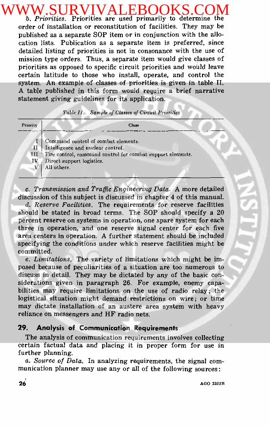
b. Priorities. Priorities are used primarily to determine theorder of installation or reconstitution of facilities. They may bepublished as a separate SOP item or in conjunction with the allo-cation lists. Publication as a separate item is preferred, sincedetailed listing of priorities is not in consonance with the use ofmission type orders. Thus, a separate item would give classes ofpriorities as opposed to specific circuit priorities and would leavecertain latitude to those who install, operate, and control thesystem. An example of classes of priorities is given in table II.A table published in this form would require a brief narrativestatement giving guidelines for its application.
Table 11I. Sample of Classes of Circuit Priorities
Priority Clan
I Command control of combat elements.II Intelligence and nuclear control.
III Fire control, command control for combat support elements.IV i)irect support logistics.V All others.
c. Transmission and Traffic Engineering Data. A more detaileddiscussion of this subject is discussed in chapter 4 of this manual.
d. Reserve Facilities. The requirements for reserve facilitiesshould be stated in broad terms. The SOP should specify a 20percent reserve on systems in operation, one spare system for eachthree in operation, and one reserve signal center for each fivearea centers in operation. A further statement should be includedspecifying the conditions under which reserve facilities might becommitted.
e. Limitations. The variety of limitations which might be im-posed because of peculiarities of a situation are too numerous todiscuss in detail. They may be dictated by any of the basic con-siderations given in paragraph 26. For example, enemy capa-bilities may require limitations on the use of radio relay; thelogistical situation might demand restrictions on wire; or timemay dictate installation of an austere area system with heavyreliance on messengers and HF radio nets.
29. Analysis of Communication RequirementsThe analysis of communication requirements involves collecting
certain factual data and placing it in proper form for use infurther planning.
a. Source of Data. In analyzing requirements, the signal com-munication planner may use any or all of the following sources:
26 AGO 2522B
WWW.SURVIVALEBOOKS.COM

(1) Troop and station list. These are particularly importantat field army level when installation of a complete initialsystem is indicated. Possible use of the electrical ac-counting machine (EAM) cards prepared by The Ad-jutant General (AG) greatly enhances the value of theselists in detailed planning.
(2) Administrative and operations overlays. For broadplanning where time is of the essence, these become theprimary source of information on distribution of re-quirements.
(3) Circuit allocation list. Refer to paragraph 28a andtable I.
(4) Equipment lists. These show the major items of signalcommunication equipment authorized to assigned andattached units (table III).
(5) Traffic studies. The primary use of traffic studies is therefinement of detailed design of the system.
(6) Past experience. Each signal communication plannerdraws on his own past experience as well as previousresults recorded in permanent records of the command.
b. Form. Where time is of the essence, the above data may beconsidered in broad planning without conversion to other forms.
(1) Division and corps. The nature of the system, the rela-tive stability of the troop list, and the time normallyavailable for planning dictate the use of requirementsdata without conversion at these levels. Broad plans canusually be developed from a study of operation and ad-ministrative overlays in conjunction with SOP circuitallocations.
(2) Field army. Where planning time is limited or whenplanning objectives involve only the expansion or modi-fication of existing systems, it is normally possible forthe planner at field army level to follow the same pro-cedures used at division and corps. If installation of acomplete system is anticipated and sufficient time andinformation are available, it is desirable to place the datain more useable form.
(a) Circuit requirement listings. These listings may beprepared manually as shown in table IV, using thetroop and station lists in conjunction with SOP circuitallocations. A faster method would be to obtain EAMcards from the AG and use them to print out units andlocations as desired. If further use of the data isanticipated in future planning, control, routing, or
AGO 2522B 27
WWW.SURVIVALEBOOKS.COM

information service, a duplicate set of cards should bemade with additional information as required. To gainaccurate totals in the preparation of the above listing,it will be noted that certain tentative decisions as toprovision of circuits must be made at this time. Forexample, according to the SOP circuit allocations, aNIKE battalion is authorized two common-user trunksfrom an area center to its unit switchboard, and anordnance company is authorized one loop from an areacenter. However, in preparing circuit requirementlistings, the planner must tentatively decide whetheran ordnance company supporting a NIKE battalionwarrants a separate circuit or should gain area accessthrough the NIKE battalion. His decision would bebased primarily on the relative location of the twounits.
(b) Requirements density overlay. This overlay has appli-cation in the planning of a complete initial installation.It is particularly effective in preparation for field exer-cises and maneuvers or occupation of planned posi-tions. It is prepared simply by transferring the totalcircuit requirements for each 10,000 meter grid squareonto a gridded overlay. This gives the planner a com-plete graphic picture of the requirements densities. Itassists in the selection of general locations of signalcenters and the division of the army area into areas ofresponsibility for signal units. Figure 9 shows a typeemployment of field army signal units based on planssuch as above.
30. General PlanThe preparation of the general plan involves the developing of
courses of action, analysis and comparison of these, and reachingof a decision. This decision is expanded into a concept to includethe following:
a. Number and type of signal installations that will comprisethe system.
b. General plan for division of responsibilities.c. Provisions for reserve.d. Broad plan for interconnections.
31. Assignment of TasksUsing the general plan as a guide, tasks are assigned to all
signal units to insure the meeting of known or anticipated require-ments.
28 AGO 2622B
WWW.SURVIVALEBOOKS.COM

l
C
'S
eq eq
i I,
I I
I I I
1<0~ m
I~~~~~~~~~~~ *1~
lHI E
l I I I l I
I v6' :l1 H I
2 I ~ IflIfl 1
"~ S.
I: -@~: 9-q~-I o- to
@ Bs ~~~dt3~~~~~~~~
0: E'
0 I~ii~Q - - -
AGO 2522B
w
I
.z
.-
0
I.-
-ZI
WWW.SURVIVALEBOOKS.COM

Table 11. Sample Circuit Requirements List Format
MAP 1:250,000 Southern France100,000 Meter Grid Square: LMi10,000 Meter (Grid Square: 2040
Circuit leluirements
Unit Coordi- Common-user Sole-urer Remarksnates
Tel TT Tel TT
14 AI)A Gp 2247 6 trunks 2 locals 8 2514 Eng Bn 2342 2 trunks 0 0 0872 QM Co 2241 2 locals 0 0 0
Note: The data contained in this list can be converted to punch card form for use with eletricalaccounting machines. The card may also contain other data useful for unit location, routingservice, and sim ilar inforation. Threse data may also be fed into automatic data proessingsystems (A l)PS).
a. Division and Corps. Tasks for signal elements at'divisionand corps level are assigned on a basis of units or installations tobe supported. Missions may include direct support missions withsecondary missions of general support to other units in the area.
b. Field Army. Signal units of the field army are assigned taskseither in terms of units to be supported or areas of responsibility.
(1) Army signal group. Communications elements of thearmy signal group normally are given missions to pro-vide direct support to command posts, operations centers,or logistical centers. These direct support missions mayor may not include provision of access systems to areacenters.
(2) Combat area signal group. Units of the combat areasignal group are given mission-type orders for the sup-port of all units in a given area of responsibility. Wher-ever possible, the planning of extension facilities is leftto the unit concerned. The area-type mission includes theprovision of access systems to major units. For example,an area signal center may be assigned a specific geo-graphical area and, in addition, be required to provideone 12-channel system to an echelon of corps which islocated in another signal center area. This is necessaryin all cases where a unit or activity is allocated access tomore than one signal center. Selection of areas of re-sponsibility is based primarily on geographical consider-ations and anticipated requirements.
(a) Complete system. The first step in assignment of tasksfor installation of a complete system is selection of
30 AGO 2522B
WWW.SURVIVALEBOOKS.COM

general locations for signal centers. These generallocations must be selected based on a study of the areaof operations, planned dispositions of major combatelements, and anticipated deployment of other ele-ments. Exact areas of responsibility can be assignedafter receipt of the troop and station list. Publicationof these lists makes available more accurate data onthe distribution of communication requirements. Finaltask assignments can thus be based on considerationboth of a unit's capability to cover an area and itscapacity for handling a communication load. Onceareas are assigned, units select exact locations con-forming as closely as possible to general locations pre-viously selected.
(b) Expansion of existing system. This normally involveseither extending the area of responsibility of a unit orcommitment of reserve signal units. Circumstancesnormally dictate extension of an area of responsibilityfirst, since all planning for expansion is based onanticipated needs. This area will normally show onlylateral and rear boundaries, with forward boundariesbeing designated later based on actual developments.When commitment of a reserve unit is necessary, thetime and general location are given and the unit isrequired to report specific locations through channels.As reserve elements are committed, every effort ismade to reconstitute this reserve by releasing unitsserving sparsely populated areas and adjusting bound-aries accordingly.
c. Construction Elements. The assignment of missions toconstruction units at all levels may be done on an areabasis, a unit-to-be-supported basis, or a combinationthereof.
32. Detailed System DesignOnce the general plan has been developed and tasks have been
assigned, the planner must go back to the original planningguidance and proceed with detailed planning. During this phase,plans are prepared to meet each specific requirement and tasks arerefined to insure meeting these requirements.
a. Extension Facilities. The plan for local distribution at eachinstallation is developed by the unit providing communicationssupport. Approval of these plans is required only in cases in-volving frequency utilization or the use of critical equipment.Completed plans are forwarded to higher headquarters for inclu-
AGO 2522B 31
WWW.SURVIVALEBOOKS.COM

sion in the overall plan, use in future planning, and provision ofinformation service.
b. Interconnections. The detailed mechanics of planning inter-connections are covered in other field manuals and in chapters 4and 5 and appendix II of this manual. This paragraph outlines anorderly procedure for the accomplishment of this planning.
(1) Planning a complete system. Essentially, the planningof a complete system is accomplished through the prep-aration of a series of charts and diagrams based on thegeneral plan, tasks assigned to units, and planning guid-ance. A logical sequence for this planning is as follows:
(a) Traffic diagrams. These are prepared for sole-userand common-user circuits and include telephone, tele-typewriter, fascimile, data, and tape-relay circuits.They show only the terminals and do not reflect therouting of circuits. The actual number of circuits arebased on SOP circuit allocations (table I) and trafficand transmission engineering data (ch. 4 and app. II).
(b) Fundamental trunking plan. This plan is a worksheetshowing only which center will have direct systems.It does not show the number of systems or the meansto be employed.
(c) Routing worksheets. Using the traffic diagrams andthe fundamental trunking plan, worksheets are pre-pared showing the routing of each circuit. Systems,channels, or means are of no concern at this point. Theprimary purpose of these worksheets is to determinethe number of systems required and the adequacy ofthe fundamental trunking plan. In the process ofpreparing the worksheets, the fundamental trunkingplan may be modified as required.
(d) Systems diagram. The preparation of a systems dia-gram involves totalling the circuits of all types be-tween centers, adding a reserve factor, and deter-mining the number of systems required. The inclusionof media to be utilized is optional on this diagram.
(e) Selection of media. If not included in the above dia-gram, selection of media is the next logical step. Thesemust be based on planning guidance. Basic consider-ations influencing the selection of media are time,characteristics of the area, enemy capabilities, logis-tics, and capabilities of troops providing support. Atthis time, the use of existing facilities must be con-sidered.
AGO 2522B32
WWW.SURVIVALEBOOKS.COM

(f) Issuance of orders. At this point, plans are formalizedand orders issued. Each subordinate element in turnissues implementing orders in greater detail.
(2) Modification of an existing system. Minor modificationsof an existing system are brought about by movement ofunits or changes in traffic flow. These normally do notinvolve command decisions and may be accomplished asa function of systems control as outlined in chapter 5.
(3) Extension of an existing system. The extension of anexisting system normally involves changes in unit mis-sions and/or commitment of additional signal communi-cation troops. These require command decisions andmust be directed through command channels. Extensionof a system must be planned based on anticipated re-quirements generated by changes in the tactical situa-tion. Sufficient latitude must be given in plans for ex-tension to provide for adjustments without furthercommand action. Procedures for planning the extensionof a system are generally the same as shown in (1)above.
33. Orders and RecordsDetailed guidance as to form and content of signal orders and
records is contained in FM 11-16. In addition, examples of ordersand records which might be used by systems control are containedin chapter 5 of this manual.
Figure 9. Type signal unit employed, field army eormmunieation system.(Located in back of manual)
AGO 2522B 33
WWW.SURVIVALEBOOKS.COM

CHAPTER 4
APPLIED SYSTEMS ENGINEERING
34. GeneralSignal communication engineering in the field army is generally
limited to consideration of single or multichannel systems. Theequipment comes in preengineered packages that are to be inte-grated in building block fashion. A need always exists for anorderly and logical method of organizing the signal communicationsystem.
35. Systems and Circuit Engineeringa. Signal communication equipment for the army communica-
tion system is listed in the tables of organization and equipment(TOE's) of the army signal units. This equipment is authorizedin standardized component groupings. Each equipment is de-scribed in its respective technical manual that covers the installa-tion, operation, and maintenance of the equipment.
b. Overall detailed guidance for systems engineering is pro-vided in the TM 11-486-series of manuals. TM 11-486-3 and TM11-486-6 are particularly applicable to the army signal system.These manuals emphasize the standard methods of using U.S.Army Signal Corps equipment. Applicable guidelines and stand-ards are to be adhered to as much as possible.
c. Communication control circuits are required to effectivelyengineer, maintain, and operate the signal communication systemsof field army, corps, and the divisions. Normally, one voice circuitwill be required from the field army, corps, or division systemscontrol center to each subordinate signal center. Where possiblethese circuits should be on a conference network. In the case ofthe field army, one teletypewriter circuit in addition to the voicecircuit will be required. Communication control circuits are some-times referred to as system(s) control circuits, engineering cir-cuits, or facilities control circuits. For the purpose of this manual,communication control circuits are those circuits established andutilized exclusively by the field army, corps, or division signalofficer in the engineering, installation, operation, and maintenanceof the signal communication system for which he has staff re-sponsibility.
d. Some of the major problems encountered in communicationsystems engineering for the field army are the selection, allocation,utilization, and administration of radio frequencies. These prob-lems are the responsibility of the frequency allocation branch,
34 AGO 2522B
WWW.SURVIVALEBOOKS.COM

communication division, army signal section. The field army is thelowest command level that has personnel specifically authorizedto handle this function. The fact that frequencies are assigned tothe field army, as an item of the signal operation instructions(SOI) of a higher headquarters, does not give the field armyexclusive rights to those frequencies. Successful communicationsystems engineering requires coordination and liaison with otherfrequency users (such as civil authorities, higher headquarters,other services, and adjacent armies). Coordination and liaisonmust be thorough and continuing to prevent interference withother essential services, such as navigational aids, traffic controlsystems, operational channels for tactical aircraft, forward air-controllers, missile guidance systems, civilian facilities, and otherexisting communication systems. Further limitations may beimposed due to political, atmospheric, and terrain problems wherethe operation is taking place.
e. To achieve maximum flexibility and to meet unforeseen dif-ficulties, as well as to provide adequate information for engi-neering purposes, a complete up-to-date record of all frequencyassignments for the field army systems and systems of otherfrequency users operating in the field army area must be main-tained. The frequency allocation branch must establish proce-dures whereby subordinate units may quickly receive frequencyassignments for new systems being established and be prepared toprovide immediate frequency changes when required. As a generalpractice, alternate frequencies cannot be provided in reserve fora unit, because of the shortage of frequencies and the basic re-quirement for spot engineering of each frequency used. Fre-quency assignment plans, as outlined in applicable technicalmanuals, are excellent when the field army is assigned an exclusiveblock of frequencies, for its own use, by higher headquarters. Inactual practice, the field army is not the only user, and frequencyassignment procedures have to be based on close coordination,available frequencies, frequency sharing, terrain, and experiencegained.
f. A standard transmission plan has been adopted by the armyto assure a system of communication with technical characteristicsthat will meet the army's need for rapid, reliable, secure, andhigh-quality service. It is based primarily on the amount of trans-mission loss which can be tolerated in a circuit between two ter-minal instruments. When the distances between units in the armyarea becomes excessive, exceptions to the army standard trans-mission plan may be justified. This may be accomplished byreducing the loss in the long-distance trunk circuit (i.e., terminalgrade to via grade trunks) and allowing more loss to occur in thelocal network.
35AGO 2522B
WWW.SURVIVALEBOOKS.COM

g. Military systems are engineered so as not to exceed a maxi-mum loss of 36 decibels (db) between terminal instruments. Whenthe loss reaches 36 db, speech may become unintelligible.
h. To meet special problems encountered under tactical condi-tions, it may be necessary to modify the standard transmissionplan. The goal is to modify the plan only as necessary to solvethese problems and without destroying its universal applicationthroughout the theater.
36. Telephone Traffic Engineeringa. The objectives of traffic engineering, as compiled in TM 11-
486-2, must be amended so that they can be adapted to a tacticalcommunication system. These objectives are-
(1) To determine the expected traffic load of the communica-tion system, and to provide this information in time topermit delivery of personnel and equipment at the propertime and place.
(2) To determine whether the trunking system meets thetraffic requirements of all switching centers.
(3) To assure that policies and practices of operating per-sonnel properly meet the needs of the commands.
(4) To coordinate with signal officers, their staffs, and oper-ating personnel of subordinate, adjacent, and highercommands, to assure that efficient use is made of allsignal equipment and personnel throughout the commu-nication system.
b. Detailed traffic engineering, in accordance with TM 11-486-2 and TM 11-486-3, is performed at field army level for the in-stallation of the field army communication system. It is a functionof the traffic branch, communication division, army signal section.The field army is the lowest command level that has personneldesignated by TOE to perform traffic engineering; however, trafficstudies should be made at all echelons as part of communicationssystem planning.
c. The design and layout of a communication system is prima-rily dictated by the signal mission. Due to the requirement forpersonal contact between commanders and staff officers and for theprocessing of large volumes of record traffic, specific engineeringof the communication system will be based on telephone and tele-typewriter requirements. In correlating these data, considerationsshould also be given to facsimile and data transmission require-ments.
d. After the field army communication system has been estab-lished, valuable traffic engineering data, such as the party called,the calling party, and the frequency and length of the calls, are
36 AGO 2522B
WWW.SURVIVALEBOOKS.COM

available. This information is collected and analyzed; then,through-trunks, direct circuits, and specially engineered local cir-cuits may be installed to improve the system. A general guide forplanning tactical signal systems, when no actual experience datais available, is provided in appendix II.
e. Operators of local switchboards, and subscribers connecteddirectly to the switchboard at signal centers, depend on the signalcenters for routing information. Routing information is furnishedthe signal centers in form of route bulletins, prepared by the fieldarmy systems control center.
37. Teletypewriter Traffic EngineeringTeletypewriter service falls into three general categories-
manually switched, tape relay, and sole user. Machines used forteletypewriter service are of two general types-page printingand tape. Tape-handling machines are not limited to use on a tape-relay system. Such machines may be used on any teletypewritersystem to provide increased speed of service through the use ofautomatic transmission; however, a page printer must be associ-ated with each tape machine used in terminal service. This isnecessary in order to produce page copy for delivery, as tape copyshould not be delivered to staff personnel. In the initial planningphases, when actual operating data does not exist, teletypewritercircuits are based entirely upon the number of teletypewritersavailable, and their capabilities. It is assumed that the existenceof teletypewriters on the TOE's of the various units, includingthe signal combat area companies, has been adequately justified.When determining circuit requirements, where data does not exist,procedures such as those outlined in appendix II may be used.When operating experience data are available, standard engi-neering procedures are used to determine the circuit requirements.
38. Manually Switched Teletypewriter SystemThe manually switched teletypewriter system includes tele-
typewriters used by signal centers, communications centers, andother subscribers, such as staff sections, units, and activities.Essentially, this system provides a teletypewriter switchboard towhich all subscribers are connected. The teletypewriter switch-board is then connected by suitable trunk circuits to other tele-typewriter switchboards. These interconnections form a networkthat provides service to all subscribers in the system. The numberof circuits for such a system is initially determined by the numberof machines in a given area and the probable traffic to be handledby each machine.
AGO 25228 37
WWW.SURVIVALEBOOKS.COM

39. Tape Relay System
a. General. The tape relay system in the field army is a net-work of point-to-point teletypewriter facilities established for thetransmission of message traffic by the torn tape method. Taperelay stations of the field army usually operate as part of thetheater tape-relay system to integrate efficiently the transmissionof traffic throughout the theater (fig. 10). To achieve a measure ofreliability within the tape relay system in the field army, taperelay stations (major and minor relays) have been dispersedthroughout the field army area. These tape relay stations areestablished at designated signal centers. While all installed armysignal centers will qualify as major tape relay stations in the taperelay system as defined by ACP 121 ( ), only specifically desig-nated army area signal centers (AASC's) will be assigned respon-sibilities as major relay stations. In the same light, the tape-relaystations of major headquarters also qualify as major tape-relaystations due to the alternate routes provided. However, the tape-relay stations of major command headquarters should be con-sidered as a minor relay station with terminal facilities andalternate routes provided for the receipt and transmission of taperelay traffic at the prerogative of the commander. This is neces-sary to avoid channelizing great amounts of relay traffic at thesignal centers of major headquarters. A tape relay system incor-porating these concepts is shown in Figure 11. In this system, alltributaries (subscribers) would be assigned a fixed three lettersuffix which would remain the same wherever they were locatedthroughout the field army. Specially designated army area signalcenters would be selected and assigned routing designators of5 letters, (i.e., UUTFM UUTFL UUTFX and UUTFG). In figure10, UUTFM is further designated as the control and informationrelay center for the field army. The remaining major tape relaystations act as control and information relay centers in their re-spective zones.
b. Routing Indicator Plan. The routing indicator plan outlinedin ACP 121 ( ) is adaptable to the tape-relay operation of thefield army. The system is based on a principle that permits quickrouting without detailed reference to a routing directory. When aunit moves from one tape-relay area to another, changes in therouting indicator and the routing directory are required.
c. Field Army Tape-Relay System. The number of tape-relaystations established for a field army is determined by the numberand location of the users and the volume of their traffic. As ageneral rule, tape-relay stations are established in the corps zoneto provide tape-relay service for the corps and divisions. Two or
38 AGO 2522B
WWW.SURVIVALEBOOKS.COM

IWR-5 DYN-0 | | AMB-50 |AY-50II| rGK IAULTFGPAI IUUTGN A UUTGNX I
x
I MON-TQ \
O TERMINA CRL-251 L \STTO 1 S LC
L DGATO S IN UUTFGIED AM A UUTFXOA O TNI UU7FL ,( UUTFG ,7 UUTFX
ARE \REEOEOBY T FO INUUTFFF I R EI UUTFAT
IF\M\ / //UU7FMDC\
L----eX_ X _ .Tptct-a-p -- xxxx -s--
OO-GO -- .... O9 LOO
-e oo -- 0 0
(NAVY)
ARE PRECEED BYUUTFFOR INTER UTHEATE R
FMII-- 21-100
GN DC) S)~~~601< NOTES: LEGEND(NWI
AGO 2522B 39
WWW.SURVIVALEBOOKS.COM

more tape-relay stations are required in the army service area toprovide normal tape-relay functions for echelons of field armyheadquarters and other units and activities.
40. Sole-User Teletypewriter .ServiceSole-user teletypewriter service is provided on point-to-point
circuits by the field army area communication system, the corpscommunication system, and the division area communication sys-tems. Sole-user circuits may be authorized when the volume orprecedence of traffic between two specific points is sufficientlyhigh to warrant them.
41. Reserve Facilitiesa. A reserve signal communication capacity should be main-
tained at each signal center to provide communications duringcritical situations. During such periods, when traffic requirementsmay temporarily exceed system capacity, service to low prioritysubscribers is curtailed. The order of precedence is recommendedby the command signal officer in accordance with the tactical sit-uation, coordinated with the general staff, and approved by thecommanding general.
b. A communication system must provide for operating sparesto replace equipment that becomes inoperative. Upon the repairof inoperative equipments they become operating spares. Theoperating spares provide a method of minimizing delays due toequipment failure. Operating spares should not be considered asa reserve facility for use in establishing additional facilities.
c. Flexibility of the field army area communication system canbe maintained by holding signal combat area companies in reserve.The reserve companies will provide the troops and equipment toestablish signal centers as required.
AGO 2522B40
WWW.SURVIVALEBOOKS.COM

CHAPTER 5
SIGNAL COMMUNICATION CONTROL
42. GeneralThe field army is a mobile and extremely flexible organization,
tailored for specific combat missions. The field army area com-munication system meets the army requirements for flexibility andreliability by circuit routing through multichannel communicationsystems. In order to achieve the necessary degree of flexibilityand reliability, the communication system must be engineered tothe known and prospective needs arising from the army's mission,and control of multichannel systems and individual circuits mustbe carefully exercised. Effective control is achieved by centralizedplanning and decentralized execution. This philosophy requiresthat systems and circuit control be effected at the lowest possiblelevel. The three types of control are-
a. Communications Control. This is the process by which com-munications resources are matched with communication require-ments generated by the overall mission of the command. Commu-nication control is a responsibility of the signal officer, it involvesplanning and operations and is normally executed through hissignal staff.
b. Systems Control. This is the detailed engineering and opera-tion of multichannel systems at each applicable level of signalcommand. Systems control sections operate within the limits ofpolicies, plans, resources, and SOP's furnished by the next higherechelon. Systems control at local facilities may be referred to asfacilities control.
c. Circuit Control. This is the engineering of individual circuitsbetween one or more signal centers or subscribers to meet therequirements of the army signal plan.
43. Field Army Organization for Signal CommunicationControl
a. At the field army level, communication control is provided bythe communications division, army signal staff. This section pre-pares broad plans for the communication network to meet bothcurrent and future communications requirements. The armysignal staff prepares the signal plan and makes recommendationsfor circuit allocations, priority of installation and rerouting, andfrequency allocation within the field army. Upon approval of theplan, mission-type orders are prepared and issued to army signaltroops. To achieve close and continuous coordination of the com-
AGO 2522B 41
WWW.SURVIVALEBOOKS.COM

munication system with the operations of the command, all or anypart of these functions may be performed by a signal elementlocated at the tactical operations center.
b. Systems control at field army level is accomplished by estab-lishing a systems control center. Because the center must haveimmediate access to both the army signal section and the areasignal centers in order to exercise its technical control over thenetwork, it is normally located near the army main command post.An alternate center is always established. The systems control.center is manned by the systems control and information sectionof the combat area signal group. The center normally operatesunder the control of the combat area signal group. Relations withunits of the field army signal battalion are governed by policiesand SOP's provided by the army signal officer. The systems con-trol center may be placed under the operational control of thefield army signal officer. The field army systems control center-
(1) Prepares and issues detailed systems and circuit ordersto implement the orders and directives of the field armysignal officer.
(2) Coordinates the operation of the network to facilitateintegration of the field army area system with systemsinstalled by subordinate (corps and division) and coequalcommands (air force and navy).
(3) Analyzes traffic to determine the current efficiency of thenetwork, and compiles experience data for future ref-erences.
(4) Prepares and issues rerouting directives and plans basedupon circuit priorities furnished by the army signalofficer.
(5) Establishes and operates a signal information servicewhich collects, records, and disseminates signal directoryservice and communication-routing information to allcomponents of the field army communication system.
(6) Coordinates the field army area messenger service.(7) Advises commanders of signal units on the location and
displacement of individual army area signal centers.(8) Maintains detailed records reflecting the current com-
munications situation.(9) Establishes standard control procedures for all subord-
inate control centers and exercises control of the fieldarmy area communication system through these sub-ordinate control centers.
c. Each signal combat area battalion establishes a systems con-trol center at or adjacent to one of the signal centers operatingin its area of responsibility. Battalion control centers are under
42 AGO 2522B
WWW.SURVIVALEBOOKS.COM
the technical control of the field army systems control center, andperform in essentially the same manner as the field army controlcenter within their geographical area. An alternate control centeris always established.
d. Each signal combat area company establishes a facilitiescontrol center at its signal center to plan and supervise internaloperation of the center and provide extension facilities to sub-scribers in its area. The facilities control center issues circuit andsystems orders to provide for local distribution within its area ofresponsibility. The facilities control center at each companyoperates under the technical control of the battalion control center.
e. The army signal battalion establishes a systems control cen-ter at the army main signal center and facilities control centersat each of the other command signal centers. The systems controlcenter of the army signal battalion is under the technical controlof the field army systems control center.
f. The corps establishes its own internal command communica-tion system, but depends on the field army area communicationsnetwork for area communication. The corps signal battalion estab-lishes a central systems control center under the supervision of thebattalion S3. Facilities control centers are established at othersignal centers serving echelons of the corps command. Facilitiescontrol centers within the corps are under the technical control ofthe corps systems control center. Circuits that enter both the armyand the corps communication systems are controlled by the higherheadquarters. In all other respects, the corps systems controlcenter performs functions for the corps communication systemsimilar to those listed for the field army systems control center.
g. The division establishes and controls its own area communi-cation system. A systems control and information center is estab-lished at or adjacent to the main signal center. Facilities controlcenters are established at each signal center. Where circuits usethe division area system and the systems of higher headquarters,circuit control is under the direction of the higher headquarters.The division system control center fulfills functions similar tothose listed for the field army systems control center. An alternatesystems control center is designated.
44. Applications of Controla. The following are some examples of how control might be
applied to typical field army problems. In all cases a sole-usercircuit is selected to simplify the explanation.
(1) A request is received at army signal center MON 711from an engineer battalion for installation of a sole-usercircuit previously allocated to it. Both terminals of this
AGO 2522B 43
WWW.SURVIVALEBOOKS.COM

circuit are now being served by MON 711. The facilitiescontrol center at MON 711 prepares plans and issues cir-cuit orders for the installation. When the circuit order iscompleted, facilities control at MON 711 informs thesystems control center of its parent battalion, which inturn informs the field army systems control center.
(2) A request is received at army signal center MON 712from a quartermaster group for a previously allocatedsole-user circuit to one of its battalions now being servedby MON 714 (a unit served by the same area signalbattalion). The request is forwarded from MON 712 tothe battalion systems control center, with all availableinformation. Since both subscribers are located withinthe area signal battalion's area of responsibility, ,hebattalion systems control center prepares plans and is-sues the circuit installation order. Upon completion ofthe installation, the field army systems control center isnotified.
(3) A request is received at army signal center MON 730from an ordnance battalion for a previously allocatedsole-user circuit to the army ordnance officer. Since thiscircuit must be routed out of the signal battalion area,the request will be forwarded to the field army systemscontrol center, where the circuit will be engineered andthe circuit installation order issued.
b. In the three cases illustrated above, the lowest unit capableof controlling the entire circuit prepared the plans and issued thecircuit installation order. It should be noted that all circuits citedwere preallocated by action of the army signal staff. This preallo-cation is a portion of signal staff planning. Requests for communi-cations not previously allocated must be referred to the armysignal staff for action.
45. Signal Center and Unit Communication Designatorsa. Basically, the signal center and unit communication desig-
nator consists of two parts, the unit telephone directory name andan exchange number. For signal communication purposes, thecommunication designator identifies command signal centers, areasignal centers, and the organizational elements and activities ofthe field army.
b. Telephone directory names are assigned to each unit equippedwith a switchboard. These names are assigned by theater head-quarters and subordinate headquarters and are published as a partof an item in the SOI or standing signal instructions (SSI).
44 AGO 2522B
WWW.SURVIVALEBOOKS.COM

c. The telephone directory name should be a simple two-syllableword that is easily understood when spoken over the telephone.
d. Field army, corps, and divisions are assigned blocks of ex-change numbers for their use. Separate companies, battalions,and other subordinate units that have switchboards are assignedseparate telephone directory names and exchange numbers. Anexample of this is the assignment of telephone directory namesand exchange numbers to engineer units. Engineer companiesoften operate away from their parent battalions; thus, they shouldbe assigned a separate exchange number for each company. Arecommended exchange number assignment follows:
(1) Exchange numbers for divisions-Element or signal center Exchange No.
Command signal centers .---------______________-___50-59Area signal centers . . ...... ................. 60-69Subordinate elements . . ................__. .. 70-249
(2) Exchange numbers for corps:Element or signal center Exchange No.
Command signal centers . ....................- 250-259Subordinate elements ...-.._____.____________ 260-699
(3) Exchange numbers for field army:Element or signal center Exchange No.
Command signal centers _____ . ____.__________.700-709Area signal centers __.-.._____ _________-.-__ __ 710-745Subordinate elements .--_______ ______________..746-2500
e. An explanation of the assignment of telephone directorynames and exchange numbers is shown below-
(1) Assume that the 10th U.S. Army is composed of the1st Corps, 2d Corps, and 3d Corps, and that the followingtelephone directory names have been assigned in thetheater army SOI:10th Army . .-. . .......................MONARCH1st Corps -______.. . ............... CRYSTAL2d Corps .-........................... DANGER3d Corps ......__......_......... AMBER
(2) Using the telephone directory names and exchangenumbers as explained above, a sample of directory list-ings would appear as follows:
Elemenmt or signal center Communication designator
10th Army main .--_________ ___________.MONARCH 700Army area signal center . .............MONARCH 71042d Missile Battalion (AJAX) Artillery .---- MOHAWK 752
Element or signal center Communication designator
1st Corps Main _____.-....___ __________. CRYSTAL 2502d Corps Main _____- _.___.____ __._____ DANGER 2503d Corps Main . .-...................AMBER 2501st Corps Artillery __.-._.____ ______.__.CRYSTAL 368
AGO 2522B 45
WWW.SURVIVALEBOOKS.COM

(3) Local extensions of each large exchange are numberedconsecutively from 200 up to the maximum number per-mitted by the size of the exchange. The two-digit num-bers 00 to 99 are not used, except for small tacticalmanual switchboards such as the SB-22 and SB-86, andthe numbers from 100 to 199 are reserved for specialpurposes. The uniform series of tactical telephone num-bers described in FM 24-20, which is directly applicableto small switchboards using two-digit numbering, mustbe modified for application to larger switchboards. Forexample, in an infantry brigade using an SB-86 switch-board, the use of a two-digit number series will permitthe assignment of number 3 to the S-3 in accordancewith FM 24-20. In a corps headquarters, using an AN/TTC-7 switchboard with 200 line capacity numbered200-399, the numbers 203 and 303 can be assigned to theG-3 section. If additional lines are required by thatsection, numbers ending in digits other than 03 must beassigned. In this event, a possible solution would be toassign 253 and 353 to the G-3 section. On the other hand,in the Army headquarters where a 600 line capacityswitchboard is used, the G-3 may be assigned all 03numbers from 203 to 703 if desired.
(4) During the displacement of any headquarters or activity,the designator used at the new location is the same asthat used at the old, except that the suffix JUMP is added.After the old location is closed out, the suffix is dropped.
(5) In certain situations, the signal combat area companiesmay be required to operate one or more satellite switch-boards from the area center switchboard. To maintainthe integrity of the area center designation, the satelliteswitchboards use the same designation as that of the areacenter, followed by word suffixes as required. Wordsuffixes, such as RED, WHITE, or BLUE, are suggestedfor this purpose. For example, a satellite switchboard ofMONARCH 710 would be MONARCH 710 RED.
(6) Telephone directory names and exchange numbers shouldnot be regarded as a code. They have no security value,but are intended only as a convenience in system opera-tion. However, telephone directories often include com-plete troop listings which might afford valuable order-of-battle information to an enemy. Therefore, it may benecessary to apply a security classification to the direc-tory, or to add the identification marking FOR OF-FICIAL USE ONLY, as determined by command policy.
46 AGO 2522B
WWW.SURVIVALEBOOKS.COM

46. System Designationa. To identify the telephone or teletypewriter multichannel
communication system between any two signal centers, it is neces-sary to use the communication designator of the two connectedsignal centers (figure 11). The same numbering method is usedfor both telephone and teletypewriter systems; however, the suffixTG is added to a teletypewriter designator. The absence of thissuffix indicates that it is a telephone system. When one or moresystems are required between two signal centers, the letters A, B,C, etc., are used immediately after the exchange number of thesignal center having responsibility for the system. Examples ofsystems designation are shown below.
(1) One voice system between 10th Army (MONARCH)signal centers 710 and 711 would be designated MON710A-711.
(2) One voice system between 10th Army signal center 710and 1st Corps main signal center (CRYSTAL 250)would be designated MON 71OA-CRY 250.
(3) Three voice systems between 10th Army signal center710 and 1st Corps main signal center (CRYSTAL 250)would be designated as follows:
MON 710A-CRY 250MON 710B-CRY 250MON 710C-CRY 250
(4) Two teletypewriter systems between 10th Army Signalcenters 723 and 717 would be designated as follows:
MON 72SA-717 TG.MON 723B-717 TG
(5) One teletypewriter system between 10th Army signalcenter (MONARCH 723) and 2d Corps main signal cen-ter (DANGER 250) would be designated MON 723A-DAN 250 TG.
b. A system may be further identified by adding suffixes to thedesignator to identify the medium of transmission, number oftelephone channels, and number of telegraph channels. Forexample, by adding the suffix V or S the transmission medium canbe shown. V would indicate VHF radio relay, and S would indi-cate spiral-four cable. By adding further numerical suffixes, thenumber of telephone and teletypewriter channels, respectively,can be indicated. Thus, system designators showing all of thisinformation would appear as follows:
MON 710A-711/V/11/4MON 710B-711/S/11/8
MON 722A-DAN 250/V/11/8
47AGO 2522B
WWW.SURVIVALEBOOKS.COM

c. The extent and manner of using these suffixes are deter-mined by the command signal officer.
Figure 11. Type army (two-corps) systems diagram.
(Located in back of manual)
47. Circuit Numbering Systema. Circuits are designated by numbers that identify the echelon
of command that initiates and establishes them. Blocks of circuitnumbers are assigned to various major command echelons through-out the theater for assignment to their circuits. These blocks ofcircuit numbers are as follows:
Circuits for circuit number block
Division ….____ ___.______ ____ _________ 1000-1999Corps ................. 2000-2999Field army .-..___.________..__________ 83000-7999Army group .-......._____ _ ___________ 8000-11999ADLOG ________________.___________ 12000-15999BALOG _____ __.._____________________ 16000-21999TALOG ____- ___________ ______________ 22000-24000Theater Army .--------------------____-____2400 0 -any limit
b. The command echelon that initiates the requirement for acircuit provides the circuit number for control and identification.This circuit number remains unchanged, even though the circuitpasses through the facilities of the systems belonging to one ormore subordinate or adjacent commands. Within the block allo-cation of circuit numbers for various command levels, prioritiesfor the installation and rerouting of circuits may be indicatedby use of especially designated sub-blocks. For example at fieldarmy (circuit numbers 3000-7999) a sub-block 3000-3500 mayindicate all priority I circuits.
c. The first three letters of the unit telephone directory nameand the circuit number are used to identify a given circuit. Forexample, MON 3001 indicates that this is circuit 3001 of the 10thArmy communication system. A circuit number with the suffixTG indicates a teletypewriter circuit; a circuit number without asuffix indicates a voice circuit.
d. To keep an accurate record of a circuit, it is necessary tomaintain the circuit order and record card. On the reverse sideof this card a trouble record may be kept. The sample circuitorder and record card format shown in table V indicates the pointof origin and termination of the circuit, the systems throughwhich the circuit passes, and the channel of the system used.
AGO 2522B48
WWW.SURVIVALEBOOKS.COM

T'able 1'. Sample Circuit Order and Record Card Formnal
3000- Circuit Order and Record Card (make entries in pencil)
(Circuit Number)From MONA RCII 700 Circuit Order Number 258To CRYSTAIL 250 )nate 28 January 1960Circuit, Contiol--MON 700
From To Channel System
MONARCH 700 MONARCH 720 1 MON 700B-720MONARCH 720 MONARCH 718 2 MON 720C-718M(ONARCH 718 MONARCH 714- 4 MON 714A-718MONARCHI 714 MONARCH 716 II MON 714B-716MONARClH 716 CRYSTAL 250 5 M()ON 716A-CRY 250
Table 17. Sample Circuit Order and Rlecord Card Formnat-Continued
(Reverse Side of Circuit Order and Record Card Format)
TR()UBLE RIECORI)
Reported Trouble found
I)ate Time By Trouble Date Time By
5/3/(;1/ 0400Z RW ower Power Failure at 5/3/01 0350Z RItWFailure MON 720.
48. Signal Locator and Routing Servicea. General. In any signal system an efficient and practical
locator and routing service is essential. Locator service providesinformation on the location and directory designation of unitsserved by the communication system. Routing service providesinformation to assist the switchboard operators in routing trafficbetween signal centers. The information necessary to providethis service is compiled and disseminated by the field army systemscontrol center and by subordinate control centers. A distinction ismade between locator and routing service for a signal system andfor unit telephone directories.
b. Responsibility.(1) In the field army area communication system, locator
and routing information is compiled and disseminated bythe field army systems control center. Personnel andfacilities for this control center are provided by the sys-
AGO 2522B 49
WWW.SURVIVALEBOOKS.COM

tems control and signal information section of the head-quarters and headquarters detachment, combat areasignal group. Personnel and facilities for subordinatecontrol centers are provided .by the battalion operationand intelligence section, headquarters and headquarterscompany, signal combat area battalions. Personnel andfacilities for facilities control are provided by the platoonheadquarters, signal center platoon, signal combat areacompanies.
(2) Locator and routing service for the corps signal systemis the responsibility of the telephone operation section,wire operations platoon, command signal operationscompany, corps signal battalion. The corps systemscontrol center establishes collection and disseminationprocedures.
(3) Locator and routing service for the division area com-munication system is provided by the division systemscontrol center, established by the division signal battalionS3. The S3 establishes collection and dissemination pro-cedures.
(4) Locator and routing records maintained at each level ofcontrol must be easily adaptable to a changing situation.Changes to the locator records are made from informa-tion transmitted between levels of control. This data istransmitted over circuits of the signal communicationfacilities provided for control purposes. The first con-trol center receiving information that a unit is leavingor entering the system is responsible for initiating thechanges on the locator and routing records.
c. Unit Locator Service.(1) Unit locator service provides geographical location
of users and the points of entry of their communicationfacilities into the field army area communication system.
(2) The unit locator service is used by signal communicationpersonnel in traffic routing, messenger service, and sys-tems engineering. Unit locator service provides, to chiefoperators and other individuals responsible for determin-ing routing, the destination in the communication systemof calls to specific units. This information, used in con-junction with routing information to that destination,allows the calls to progress in accordance with an estab-lished traffic pattern.
(3) The field army systems control center prepares a unitlocator register that shows all organic and attachedunits, their location, their unit directory designations,
50 AGO 2522B
WWW.SURVIVALEBOOKS.COM

and the signal center serving them. Units not part of, butserved by, the signal system are also shown. The locatorregister is issued, initially, to- all signal centers. Onceissued, the register is maintained by the signal center.This is done by posting information received throughcontrol channels. A type format for a locator register isshown in table VI.
d. Routing Service.(1) Routing information is furnished the signal centers to
assist the switchboard operators in routing trafficthrough the communication system. This information isfurnished to the switchboard operators in the form oftraffic diagrams and route bulletins.
(2) Routing information, used principally at signal centers,is compiled and disseminated by the control centers ofthe communication system. Local switchboard operatorsdepend on signal centers for routing information.
(3) Each switchboard operator requires routing informationto be able to contact all units served by the communicationsystem and to gain entrance into higher, lower, andadjacent communication systems. The telephone routebulletin and the telephone traffic diagram serve as themajor routing guides. Additional assistance can be ob-tained from the information and directory operator.Telephone routing service is compiled and used as fol-lows:
(a) The field army systems control center prepares amaster telephone traffic diagram which is issued tosubordinate signal centers. This diagram shows com-mon-user trunks of the communication system. Eachsignal center indicates on its copy of the traffic dia-gram all trunks to local exchanges within its area ofresponsibility.
(b) The field army systems control center maintains atraffic diagram of the field army area communicationsystem to show trunks to the theater communicationsystem and to adjacent communication systems.
(c) Telephone route bulletins are maintained at all signalcenters. A route bulletin is a list of all units served bythe communication system showing the signal centerthrough which each may be reached. Additions ordeletions are transmitted immediately, by the signalcenter initiating the change, over a communicationcontrol circuit to all other signal centers in the bat-talion area and, in the case of the field army area com-
AGO 2522B 51
WWW.SURVIVALEBOOKS.COM

munication system, to the battalion systems controlcenter. The battalion systems control center transmitsthe change to the field army systems control centerwhere it is simultaneously transmitted to all otherbattalion systems control centers.
(4) At least once a day, or as often as necessary, the fieldarmy systems control center sends a complete new routebulletin to each area and command signal center overcontrol circuits.
(5) The field army systems control center has at least oneinformation and directory operator to provide routinginformation to the signal center chief operators fortrunking to higher, lower, and adjacent communicationsystems, or to assist in routing calls within the communi-cation system. A type format for a route bulletin isshown in table VII.
(6) Routing service is provided by the first signal centerswitchboard operator. The local operator extends thecall to the first signal center switchboard operator.The first signal center switchboard operator then routesthe call to its destination and remains on the connectionuntil the final operator has received and understood thefinal connection order.
49. Records and ReportsAt field army, corps, and division level, the systems control
centers keep the signal sections informed as to the current opera-tional status of the signal communication system and the avail-ability of personnel and equipment to meet additional operationaldemands. To accomplish this and to assure effective, accuratecontrol and operation of the signal system at each level, the appli-cable control centers must maintain and have available certainessential records. These may include, but will not be limited to,the following:
a. Line Route Map. A line route map is a map overlay that in-dicates the exact route and number of wire lines. Guidance as toformat is contained in FM 24-20.
b. Radio Relay Systems Map. A radio relay systems map (fig.12) is a map overlay that indicates locations of radio relayterminals and intermediate relay stations, operating radio fre-quencies, magnetic azimuth of antenna orientation, and locationof signal centers being served by the radio relay terminal sites.At division and corps level it is prepared and disseminated as anappendix to the signal battalion operations order; at field army itis prepared and issued by the field army systems control center.
52 AGO 2522B
WWW.SURVIVALEBOOKS.COM

.OC C
'3
o0
xI-
CC
se.
-tz'
C)
c
3.4
-S
53
Cv,
C,,
o
K?.-
Al
cV.
40
CCBE.Q
u
C)
0
4.
C),
C)
0
u
stel
eq
u
zc
AGO 2522B
m by, C +.4
1
WWW.SURVIVALEBOOKS.COM

Table VII. Sample l10th Army Telephone Rote BlHilelin Format
Effective: 010500 I)eC. 1960
Unit collmmunication Communication designator ofdesignator signal center providing ervicee
CRYSTAL. 250 MONARCH 715/716JOKER 50 MO()NARCH 718MONARCH 700 MONARCH 720/726/701/710MONARCH 701 MONARCH 723/729/700MONARCH 927 MONARCH 715
c. Radio Net Diagram. A radio net diagram is a graphic dis-play of the employment of AM and FM radio sets within a desig-nated area. It shows number and type of sets, arrangements andparticipants of the various radio nets, assigned frequencies andcall signs, and other related data as required. At division levelit is prepared and disseminated by the systems control center ofthe signal section; at army, it is prepared and disseminated by thefield army signal section.
d. Communication Systems Diagram. A communications sys-tems diagram is a working document which shows the multi-channel systems available for use. It is used in systems controlcenters as an aid to circuit routing. Each control center pre-pares a communication systems diagram showing its own areaof responsibility (fig. 11).
e. Telephone Traffic Diagram. A telephone traffic diagram is agraphic display of the common-user telephone trunk circuits be-tween signal centers.
(1) At division level, the diagram (fig. 13) is preparedand disseminated by the division systems control centeror the signal section and shows the number of common-user telephone trunk circuits in the division area com-munication systems. It also shows the number of com-mon-user trunk circuits between the division system andhigher adjacent commands.
(2) At army level, the diagram (fig. 14) is prepared anddisseminated by the army signal section. It shows accesspoints to the telephone switching centers of higher,lower, and adjacent commands and is used by the tele-phone operators for routing calls.
f. Teletypewriter Traffic Diagram. A teletypewriter trafficdiagram shows the number of common-user teletypewriter trunkcircuits between signal centers.
(1) At division level, it shows the number of common-user
54 AGO 2522B
WWW.SURVIVALEBOOKS.COM

teletypewriter trunk circuits within the division areacommunication systems. It also shows the number ofcommon-user teletypewriter circuits between the di-vision system and higher and adjacent commands (fig.15).
(2) At army level, it shows access points to teletypewriterswitching centers of higher, lower, and adjacent com-mands (fig. 16). It is used by the teletypewriter switch-board operator for routing teletypewriter calls.
g. Division Sole-User Trafic Diagram. A division sole-usertraffic diagram contains the origin, number, destination, androuting of all sole-user telephone and teletypewriter circuits in thedivision area communication system. In addition, it shows soleuser circuits established by higher or adjacent commands thatoccupy channels of any of the division multichannel systems. Thediagram is prepared by the division systems control center.
h. Army Sole-User Traffic Diagram. An army sole-user trafficdiagram (fig. 17) shows the origin, number, and designation ofall sole-user telephone and teletypewriter circuits approved forinstallation within the field army. It is prepared by the armysignal section and is included in the signal portion of the ArmySOP. It is used by subscribers as a record of their allocation ofsole-user service, and by systems control centers in the preparationof detailed circuit orders.
i. Unit Locator Register. A unit locator register gives theexact geographical location of units, unit designations, and theirpoints of access to the particular communication system. Thisinformation is used by signal communication personnel in rout-ing of telephone calls, teletypewriter messages, and messengers.Units not part of but served by the communication system are alsolisted. The unit register, which is issued to all signal centersupon initiation of operations, is maintained by the individual signalcenters. This is done by posting the changes as they occur. Arecommended format is shown in table VI.
(1) At division level, the register is prepared by the divisionsystems control center.
(2) At army level, the register is prepared by the field armysystems control center.
j. Telephone Route Bulletin. The telephone route bulletin is analphabetical listing of all units by telephone directory name orcommunication designator. It lists the signal centers throughwhich each of these units can be reached. It is used by the signalcenter telephone switchboard operator routing trunk calls. Thebulletin is prepared and maintained by all command and areasignal centers. A consolidated route bulletin is distributed peri-
AGO 2522B 55
WWW.SURVIVALEBOOKS.COM

odically by the field army systems control center. Table VIIshows a type telephone route bulletin.
k. Circuit Register. A circuit register format (table VIII)is a numerical listing of the block of circuit numbers assigned tothe particular unit. Columns in the register indicate the circuitnumber, the type of circuit, the point of origin, and the destination.The register is used by control centers to identify circuits thatoriginate within the particular communication system. As eachcircuit is assigned a number, the register is posted and a circuitorder and record card is prepared. As each circuit is cancelled,the information is posted on the register and the circuit recordcard is retired.
Table VIII. Sample Circuit Register Formal
Circoit number Tylpe ircuit Origin Destinati)n
3000 Tel IMON-700 CRYSTAL.--2503001 Tel MON-700 CRYSTA L--2503002 Tel MON-700 M( )N--7023003 Tel M()ON-700 MON-7023004 Tel MON-700 MON--7023005 Tel MON 700 MON--7023006 Tel MON-700 10N--7023007 Tel M()N-700 MON--7203008 'Iel MON-700 MON-7203010 T MON-700 M()N--72
I. Circuit Order and Record Card. A circuit order and recordcard contains information pertaining to the facilities used on eachcircuit (channel number, system number, or facility used). It alsoindicates the circuit order number and the effective date. The con-tents of this card are transmitted in abbreviated format and con-stitute a circuit installation order to the signal center involved.The circuit order and record card is prepared and maintained atcontrol centers. A type circuit order and record card format isshown in table V.
m. Carrier System Record Card. A carrier system record cardindicates the facility used, the channels available for use, thespare channels, the origin and destination of each channel in use,and the circuit number for each circuit occupying a channel in thesystem. The card is prepared and maintained at control centers.A card is prepared and maintained for each carrier system oper-ated. The reverse side of the card is used to indicate trouble onthe system or trouble on individual channels. One method of useis to remove the card from the operational file and place it in an
56 AGo 2s522B
WWW.SURVIVALEBOOKS.COM

outage file during periods that the system is out because of trouble.A record of the time in and time out maintained on the reverse ofthe card will be the basis of a history of the system that can beused for many purposes. A type format is shown in table IX.
Table IX. Sample Carrier System Record Card Format
M(ON 700A-270 Carrier System Record Card
(System Number)Facility used: Radio relay Terminal Equipment AN/TCC-7
Channel From To Circuit No.
I ~ IMON 700 MON 701 37012 C:3 MON 700 G3 CRY 250 37043 MON 700 CRY 250 37694 MON 700 CRY 250 37705 MON 700 MON 701 37900 MON 710 MON 711 38107 MON 710 MON 711 38118 Spare9 MON 710 MON 711 SI() 43'
MON 710-711 TG10 SpareII Spare12 Spare
see reverse sidesystem installation order
Table IX. Sample Carrier System Record Card Format-Continued
(reverse side)
Carrier System Record Card Format
Time ,late out Time date in Remarks
140012Z 140112Z System out. Generator trouble, relay No. I190012Z 191504Z Channel 12 out. Bad ringer, terminal "B".
n. Carrier System Record Chart. A carrier system record chartillustrates the individual systems that terminate at a particularsignal center and shows the use made of each channel. Thechart is prepared by and maintained at the individual signal cen-ters. In some cases, it may be necessary to prepare two charts toseparate the telephone carrier systems and the teletypewritercarrier systems. If this chart is covered with clean acetate, systemchanges may be made with a grease pencil. A type format isshown in table X.
57AGO 26522B
WWW.SURVIVALEBOOKS.COM

C
i
C
AGO 2622B
WWW.SURVIVALEBOOKS.COM

50. Electronic Accounting Machine ApplicationsBy using the systems, units, and circuit designators as dis-
cussed above, the problem of systems control and circuit controlbecomes semi-mechanical in nature, and hence is amenable to EAMand ADP applications. Figure 18 represents a possible machinecard layout format, applied to the problem of unit designation,location, communication requirements, signal center providingservice, etc. Such a card, by either machine sorting or ADPapplication, could be used to provide telephone directories, unitlocator files, signal center communications loads, etc. Similarly,a circuit order and installation card may be punched (fig. 19)showing the maximum center and system routing (seven signalcenters), and could be used as both a circuit order and a circuitrecord. Such a card, by machine sorting, could be used to indicatecircuit routing, circuit and system utilization at each signal cen-ter, systems record cards, etc. Through ADP application, thesame input card could indicate system and channel availability,system and channel usage, etc.
51. Telephone Directory ServiceAt division level, a telephone directory is prepared by the divi-
sion signal section and distributed as an SOI item. At army level,it is prepared by the field army signal section. The directory listsall assigned and attached units and their associated directorycommunication designator names. It also lists those units thatare not a part of, but which are served by, the particular signalsystem. The control center notifies all'signal centers of changesto the telephone directory. Signal centers and units prepare tele-phone directories in accordance with local requirements.
a. Subordinate control centers notify the higher control centeras soon as possible when circuits to units, located within their areaof responsibility, have been installed. The information to be pro-vided to the higher control center normally includes, but is notlimited to-
(1) Unit designation.(2) Communication designator name of unit, if not listed
in directory.(3) Coordinates of unit.(4) Type of circuit provided.
b. When units served by a signal center move, they notifythe signal center concerned- before disrupting their communica-tion.
Figure 12. Type field army (two-corps) radio-relay system map.
(Located in back of manual)
AGO 2522B 59
WWW.SURVIVALEBOOKS.COM

Figure 13. Type infantry division telephone traffic diagram.(Located in back of manual)
Figure 14. Type field army telephone traffic diagram.(Located in back of manual)
AGO 2522B60
WWW.SURVIVALEBOOKS.COM

AGO 2522B
WWW.SURVIVALEBOOKS.COM

Figure 16. Type field army teletypewriter traffic diagram.
(Located in back of manual)
Figure 17. Type army sole-user telephone and teletypewriter traffic diagram.
(Located in back of manual)
Figure 18. Format for type machine card layout for unit designator card.
(Located in back of manual)
Figure 19. Format for type machine card layout for circuit order andrecord card.
(Located in back of manual)
62 AGO 2522B
WWW.SURVIVALEBOOKS.COM

CHAPTER 6
SIGNAL CENTER DISPLACEMENT
52. Displacement of Field Army Signal Centersa. There are several methods of displacing the field army main
and the field army alternate signal centers. Based on existingcircumstances, the field army signal officer decides the method tobe used. Two methods are discussed below:
(1) Signal facilities that are not absolutely necessary at theold command post are moved and established at the newcommand post. This permits the headquarters to beginoperations at the new command post. Signal facilitiesare moved to the new location as quickly as the situationpermits. The old command post is finally closed out.
(2) Operations are closed out completely at the old commandpost, and the headquarters and signal facilities are movedto the new command post. With this method, armyalternate headquarters must exercise control until thenew CP is ready to resume control. Army alternate isthen closed and moved to its new location.
b. The nature and size of the system requires displacementof the field army area signal centers by establishing new centersin the forward areas and closing out those in the rear areas.
(1) As corps and divisions move forward, the field armyarea signal centers in reserve are committed to forwardareas to continue area support.
(2) Field army area signal centers in the army servicearea are phased out to provide reserve or immediate dis-placement units. Two methods used to close out area sig-nal centers are:
(a) The signal center is phased out by rerouting its trunkcircuits and by connecting the units left within thearea to another area signal center.
(b) Signal combat area companies are relieved by thesignal operations platoon of the headquarters andheadquarters company, signal combat area battalion.This platoon may be used under the following condi-tions:
1. When the units requiring support in an area servedby an area signal center are reduced in number tothe extent that a full signal combat area company isno longer required.
AGO 2622B 63
WWW.SURVIVALEBOOKS.COM

2. In an area where switching and trunking facilitiesare required, but where no units are located.
c. When the army rear boundary is to be moved forward, thesignal section of field army headquarters coordinates with thesignal section of the theater army to assure that signal communi-cation is provided to units that remain in the area.
d. Signal combat area companies held in reserve remain underthe control of their parent battalions, unless operational con-siderations make this impossible. These reserve companies arekept in a ready status and should be located to facilitate futureemployment.
53. Displacement of Corps Signal CentersFrequent movement of echelons of corps headquarters causes
signal communication displacement operations to be carried oncontinuously. Proposed future locations of command posts areselected and surveyed, plans are developed for physical rearrange-ment and electrical rerouting of communication circuits, and alleffected elements are advised of the action to be taken to effect thedisplacement. Physical movement of personnel and equipment isthen initiated. This movement is conducted in phases that permitestablishment of signal communications prior to the time opera-tions are scheduled to begin at the new command post. The phasesalso must permit communication to continue at the old commandpost until communication is established at the new command post.As a result, personnel and equipment must be available for dis-placement operations.
54. Displacement of Division Signal Centersa. General. Signal centers of the division area communication
system must be able to displace without interrupting the con-tinuity of service to users of the system. The task of providinguninterrupted communication is made easier by intelligent, de-tailed advanced planning on the part of the division signal officerand his close coordination with the division staff, particularlyG3. Certain basic principles to be considered in any displace-ment plan are to:
(1) Provide continuous communication service.(2) Establish a complete and comprehensive procedure for
any contingency. This procedure must be followed bypersonnel who install and operate the system, particularlyradio relay and circuit control personnel.
(3) Establish and follow a standardized method of circuitcontrol.
64 AGO 26522B
WWW.SURVIVALEBOOKS.COM

(4) Maintain displacement equipment in a ready state andlocate the equipment where it may be rapidly committed.
(5) Make maximum use of the alternate routing capabilitiesprovided by the division area communication system.
(6) Make provision for continuous service to subscriberssubsequent to displacement of a signal center.
b. Divisibn Main Signal Center. Methods of displacing com-mand signal centers vary with tactical requirements. Accordingly,it is impractical to explain every imaginable situation. The dis-placement procedures listed below are based on division main'sdisplacement to the division advance signal center; however, theidentical basic principles apply for displacement of all commandsignal centers.
(1) Radio relay facilities. Radio relay equipment from thereserve pool is moved to and installed at the new location.Existing divisicr., main radio relay circuits are thenmonitored and taken over by the advance group whenthe command post moves forward. Old division maincloses down and its radio relay equipment reverts to thereserve pool at the new location.
(2) Patching and Switching Facilities. Since patching andswitching facilities are already established at divisionadvance, the division main circuits need only be patchedinto or through them. After the old division main signalcenter is closed out, the patching and switching equip-ment can either be displaced to the next location ofdivision advance or reverted to the reserve pool.
(3) Radio facilities. It may be necessary to combine certainradio nets to make a displacement. When this is required,the division signal officer determines which nets are tobe combined. The radio/wire integration service oper-ated at division advance provides integration facilitiesfor elements of division main as they move into theirnew location. Full radio facilities are reestablished asrapidly as personnel and equipment arrive at the newlocation.
(4) Communications center facilities. These facilities arealready provided at division advance. When divisionmain closes out the old signal center, the communicationscenter equipment is moved to the new location of divi-sion main or to a new division advance location.
c. Division Advance Signal Center. The division advance signalcenter affords close control of the forward elements of the divi-sion, provides alternate routing, and may serve as a location for
AGO 2522B 65
WWW.SURVIVALEBOOKS.COM

the displacement of the division main. The division advance signalcenter generally displaces more frequently than division main.
(1) Radio relay facilities. Radio relay facilities are dig-placed by moving the reserve equipment to the new divi-sion advance location, monitoring the present radio relaysystem, and taking over at a predetermined time. Afterthe radio relay system has been taken over at the newlocation, the released radio relay terminals at the olddivision advance represent a reserve pool of equipmentfor use during future displacements.
(2) Patching and switching facilities. The telephone sectionof the command signal center platoon, command opera-tions company, is not authorized patching and switchingfacilities for displacement purposes. However, there aresufficient switching facilities available in the other tele-phone sections of the signal battalion that may be usedto support a displacement of division advance.
(3) Radio facilities. It may be necessary to combine certainAM radio nets to facilitate a displacement. Upon com-pletion of the displacement, these facilities are restoredat the new location to their full capabilities as rapidlyas possible. The FM facilities can be displaced withoutany appreciable reduction of service.
(4) Communications center facilities.. No displacement facili-ties are provided. To displace communications centerfacilities at division advance, facilities are closed down,moved to the new location, and then reestablished.
d. Forward Signal Centers.(1) General. Forward signal centers normally can displace
by employing only their authorized personnel and equip-ment. However, the division signal officer may augmentany signal center with personnel and equipment avail-able elsewhere in the signal battalion.
(2) Radio relay facilities. Radio relay facilities at a for-ward signal center may consist of three radio terminals(two in operation and one in reserve). Figure 20 indi-cates that one terminal is used as a single terminal insystem TAN 51A-61 and another terminal is used as adouble terminal in a systems TAN 60A-61 and TAN61A-62. Methods of displacing radio relay facilities ata particular forward signal center (in this case, center61) are described in (a) through (d) below.
(a) The reserve terminal moves forward to establish anew area signal center (TAN 61 JUMP).
66 AGO 2522B
WWW.SURVIVALEBOOKS.COM

(b) System TAN 51A-61 JUMP is established by usingone-half the reserve terminal that displaced to 61JUMP.
(c) System TAN 51A-61 is closed out, and that terminalis displaced to 61 JUMP, where it establishes systemsTAN 60A-61 JUMP and TAN 61A-62 JUMP.
(d) Systems TAN 60A-61 and TAN 61A-62 are closedout when the command closes, and this equipment isdisplaced to forward signal center TAN 61, (formerly61 JUMP) and is held in reserve for the next dis-placement.
(3) Patching and switching facilities. Each forward sig-nal center is authorized two patching panels (one inoperation and one in reserve). When an area signalcenter displaces, the reserve patch panel moves forwardto the new location, where it is installed to handle theswitching and patching operations at the new signal cen-ter.
(4) Radio facilities. Radio facilities provided by a forwardsignal center are a radio/wire integration station and anFM radio set operated in the signal battalion command.
(5) Communications center facilities. No displacement facili-ties are provided. In order to displace the communica-tions center facilities at an area signal center, the facili-ties must be closed down, moved to the next location,and then reestablished.
Figure 20. Type diagram for displacement of forward signal center radiorelay facilities (worksheet).(Located in back of manual)
AGO 2522B 67
WWW.SURVIVALEBOOKS.COM
APPENDIX I
REFERENCES
1. Army RegulationsAR 105-15 Army Field CommandsAR 320-5 Dictionary of United States Army TermsAR 320-50 Military Abbreviation and Symbols
(Authorized Abbreviations and BrevityCodes).
AR 380-40AR 380-41
Safeguarding CryptomatterControl of Cryptomaterial
2. Field ManualsFM 11-8FM 11-14
FMFMFMFMFMFMFMFMFMFMFMFMFMFMFMFMFM
11-1511-1611-5711-8611-9211-9521-521-621-3024-1724-1824-2032-5100-5100-10100-11101-5
FM 101-10
3. DepartmentDA Pam 108-1
DA Pam 310-1
Field Radio Relay TechniquesArmy Signal Supply and Maintenance Bat-
talion.Signal Cable Construction BattalionSignal Orders, Records, and ReportsSignal Battalion, Airborne DivisionCombat Area Signal Battalion, ArmyCorps Signal BattalionArmy Signal BattalionMilitary TrainingTechniques of Military InstructionMilitary SymbolsTactical Communications Center OperationField Radio TechniquesField Wire and Field Cable TechniquesCommunications Security (U)Field Service Regulations; OperationsField Service Regulations; AdministrationSignal Communications DoctrineStaff Officers' Field Manual; Staff Organiza-
tion and Procedure.Staff Officers' Field Manual: Organization,
Technical and Logistical Data.
of the Army PamphletsIndex of Army Motion Pictures, Film Strips,
Slides, and Phono-Recordings.Military Publications: Index of Administra-
tive Publications (Army Regulations, Spe-cial Regulations, Circulars, Pamphlets,
AGO 2522B68
WWW.SURVIVALEBOOKS.COM

DA Pam 310-2DA Pam 310-3
DA Pam 310-4
DA Pam 310-7
Commercial Traffic Bulletins, MilitaryTraffic Management Bulletins, (JointChiefs of Staff Publications, General Orders,and Bulletins).
Military Publications: Index of Blank FormsMilitary Publications: Index of Training Pub-
lications (Field Manuals, Reserve OfficersTraining Corps Manuals, Training Cir-culars, Army Training Tests, War Depart-ment and Department of the Army Posters,and Firing Tables and Trajectory Charts).
Military Publications: Index of TechnicalManuals, Technical Bulletins, Supply Bul-letins, Lubrication Orders, and Modifica-tion Work Orders.
Military Publications: Index of Tables ofOrganization and Equipment, Type Tablesof Distribution, and Tables of Allowances.
4. Technical ManualsTM 11-486-1
TM 11-486-2
TM 11-486-3
TM 11-486-6
TM 11-486-7
TM 11-486-10
TM 11-486-11
Electrical Communications Systems Engineer-ing: Military Communications Systems.
Electrical Communication Systems Engineer-ing: Traffic.
Electrical Communications Systems Engineer-ing: Transmission and Circuit Layout.
Electrical Communication Systems Engineer-ing: Radio.
Electrical Communications Systems Engineer-ing: Power.
Electrical Communications Systems Engineer-ing: Handbook.
Electrical Communications Systems Engineer-ing: Definitions and Abbreviations.
5. Allied Communication PublicationsACP 121ACP 194A
Communication Instructions-General (U)BAFCOM-US Army Communication Fre-
quency Plan (U).
6. Training CircularDA Training Cir- Tactical Operations Center
cular 101-2
AGO 2522B 69
WWW.SURVIVALEBOOKS.COM
APPENDIX II
GUIDE FOR PLANNING TACTICAL SIGNALCOMMUNICATION SYSTEMS
1. GeneralTo assure the greatest possible reliability, traffic engineering
factors should be developed from actual operating experience.Where such factors do not exist, standard factors must be used.This appendix gives some general guidance in planning tacticalcommunication systems.
a. Communication equipment necessary for operating com-munication systems at various levels is authorized in the form ofstandardized component groupings. Each of the components usedis described in a technical manual which covers the installation,operation, and maintenance of the equipment.
b. Engineering of field army communications is relativelysimple, because of the inherent capability of the type of equip-ment authorized. A major problem is the selection, allocation,and utilization of radio frequencies. Various frequency assign-ment plans are described in applicable equipment and engineeringmanuals and in ACP 194A. Another problem is the selection,allocation, and distribution of cryptosystems to insure compatiblecryptonetting.
c. Overall guidance for systems engineering is provided inthe TM 11-486-series of manuals. These guidelines and standardsshould be adhered to as far as practicable.
2. TelephoneTo determine the number of long-distance trunks required for
an army area signal center, it is necessary to first determine howmany local trunks and loops will be connected to the switchboardof the area signal center. The following steps may be used toestimate the number of long-distance trunks required to supportthe subscribers of a given area signal center.
a. Total the local trunks and loops terminated at the signalcenter. This total may be obtained by totaling the number oftelephone trunks and loops on the requirements density overlaypertaining to the area of responsibility of this signal center.See table IV.
b. Add to the number of loops calculated a general planningfactor of 25 loops for use within the immediate vicinity of thearea signal center.
70 AGO 252211
WWW.SURVIVALEBOOKS.COM

c. Apply the following formula to determine long-distancetrunks required for this center.
Loops served x CR + local trunks x CR*Average calls per hour
(1) CR represents the long distance calling rate for sub-scribers connected to the area center, by means of tele-phone loops. CR may be assumed to be 0.5 call perhour for each loop.
(2) CR* represents the long-distance calling rate for eachlocal trunk connected to the area center switchboard.CR* may be assumed to be 1.5 calls per hour for eachlocal trunk.
(3) The average calls per hour represents the average num-ber of calls that may be handled at the area centerswitchboard on one long distance trunk. This constantmay be assumed to be 7.5 calls per hour for each longdistance trunk.Example:An area center anticipated that it will provide 80 localtrunks to subscribers in its area. It anticipates installinga total of 60 loops in its area of responsibility. Applyingthe formula above to these anticipated requirements wehave:
loops served x CR + local trunks x 1.57.5
= 60 x 0.5 + 80 x 1.57.5
30 + 120 = 20 long distance trunks required to satisfy the antici-7.5
pated subscriber load.d. After the area signal center is installed, it is imperative
that actual traffic data be obtained and analyzed to accuratelymodify the common user telephone system to meet requirementsin a realistic manner.
3. TeletypewriterWhen actual operating data are not available, use maximum
machine capacity to determine teletypewriter circuit require-ments. Use TOE's to determine the number of teletypewritermachines available; use the procedures below to determinethe number of circuits required for their operation.
a. Tape Equipment. To determine the maximum busy-hourgroup count, multiply the number of tape machines in the signal
AGO 2G22B 71
WWW.SURVIVALEBOOKS.COM

center by 20,000. (Tactical tape machines are capable of handlingapproximately 20,000 groups per day). Use this group countfigure and refer to the tables in the TM 11-486-series to arrive atthe approximate number of trunks required.
b. Manual Switched Service. Switched service, in this in-stance, means the use of keyboard-operated machines connectedto a switchboard. To determine the maximum busy-hour groupcount, multiply the total number of keyboard operated machinesby 10,000. Use this figure and refer to the appropriate tables inTM 11-486-series of manuals to determine the number of trunksrequired.
4. Sole-User CircuitsMessage precedence and traffic volume are the two considera-
tions in justifying allocation of circuits on a sole-user basis. Re-quirements must be verified by coordination with appropriate staffsections and with the units that generate traffic requirementsbased on operational needs.
AGO 2522B72
WWW.SURVIVALEBOOKS.COM

BY ORDER OF THE SECRETARY OF THE ARMY:
Official:J. C. LAMBERT,
Major General, United States AiThe Adjutant General.
Distribution:Active Army:
CNGB (50Tech Stf, DA (2) ex
CSigO (15)Tech Stf Bd (1)USCONARC (5)OS Maj Comd (10)MDW (1)Armies (10) except
Seventh USA (30)EUSA (25)
Corps (5)Div (10)Bde (2)Bg (1)Bn (1) except
TOE 11-5 (25)TOE 11-15 (25)TOE 11-25 (25)TOE 11-45 (25)TOE 11-55 (25)TOE 11-85 (25)TOE 11-95 (25)TOE 11-155 (10)TOE 11-555 (25)
cept
G. H. DECKER,General, United States Army,
Chief of Staff.
'my,
Svc Colleges (2) exceptUSACGSC (150)
Br Svc Sch (5) exceptUSASCS (1500)PMGS (100)US ARADSCH (10)USAAVNS (30)AMSS (25)USAIS (20)USASESCS (100)
USMA (5)PMS Sr Div Units (4)PMS Jr Div Units (4)PMS Mil Sch Div Units (4)ACS (5)USASRDL (5)USAEPG (10)MAAG (2)Mil Msn (2)Units organized under fol-
lowing TOE:11-22 (10)1132 (10)11-66 (5)11-137 (10)
NG: State AG (3); Units-same as Active Army except allowance is onecopy to each unit.
USAR: Same as Active Army except allowance is one copy to each unit.For explanation of abbreviations used, see AR 320-50.
*U.S. GOVERNMENT PRINTING OrFFICE: 1961-610517
AGO 2522B 73
WWW.SURVIVALEBOOKS.COM

6XXXX
NOTES:I WHEN SPIRAL-FOUR CABLE S /XXXX SIG I co SPT
INSTALLED TO PROVIDE THESE SIG CENSYSTEMS, THE CABLE IS INSTALLED10 XX CENBY THE CABLE CONSTRUCTIONBATTALION. XXXX 16 XXX XXX-_-
2. THE EXTENSION SYSTEMS TO THE 14 SIDIVISIONS NORMALLY TERMINATE LTNAT DIVISION SUPPORT COMMIAND /xxx f
l 717 \ / \ _ CO~~~ICEN \IG CEN X/G7171- X||XX8-XA
MON 02X:h XX X -0LEGEND: ALTN-4ULTNHANNEL GYGTEMSIy THEATER \C;7V GIC CEN ___-- \ > /XXXX / \ /XXXXX 2 e_ <-- _# '
MULTICHANNEL SYSTEMS CPROVIDED BY COMBAT AREA THETERMON XXXSIGNAL COMPANIES Ax718[XOX
x P.OIN T1 ' 'S L P MO---- MULTICHANNEL SYSTEMS IF
ALPROVIDED BY FIELD (NOTEXOPERATIONS COMPANY, MIARMY SIGNAL BATTALION.
----- MULTICHANNEL EXTENSIONSYSTEMS PROVIDEDO BYCOMBAT AREA SIGNAL --xxCOMPANIES. N
S EN SIG I CN
X)XX X X XXXX
MON PO EN "MD X JPX
MON X SGCEo -
REARII~ ~ ~ ~ ~ ~ ~ ~ ~ ~ ~ ~~M- TO AL AC D DX
BI SlO CEN~~~~ ~T AA AMIG N
~ -XXX
POXXXXX \YOVD
79FMIP-21-1 TO ALL ATTACHED INF NV2. BATT SRCUITS NOT SHOWN,ITO ADJACENT ARMY AREASIGNAL CENTERS FMII-21--.
gigure 1. I ype feld army multichannel communication system. Figure 1Figusre 2. Corps cominIiication system integrated with the field army Figure 2
conmmnluIIication system, schematic diagram.
WWW.SURVIVALEBOOKS.COM

LEGEND:------ DESIGNATES AREA SIGNAL BATTALION'S
AREA OF COMMUNICATION RESPONSIBILITY.
)
-° IY! r./FM11-21-33
Figure 9. Type signal unit employment, field army communication system. Figure 9
WWW.SURVIVALEBOOKS.COM

IIL-G001y
NON
11 =VO11 NON
HH
a
ah
Figure 11. Type army (two-corps) systems diagram.
O
0.ho0.
C,
0
N0
0C,'r\
* -n .cm
::N i
a o
I5ci-
- 9Z-8LZL NOn
-921 -VtZI NON
-9ZZ-VSZ NOn
6ZL-¥SZ£ NOW
Iwe
;iue
o
Figure I ]
WWW.SURVIVALEBOOKS.COM

xxxxMoW 713
aje ceE
ELEV563
/~~D
2~~~~~~
4 ALTN /
~~ (~~NOTE 1
ON 711 ELEV·c,
NOTES: 4 61.SYSTEM DESIGNATED AS RESERVE; TO BE PLACEOD IN OPERATION xx
ON ORDER WHEN SPIRAL-4 SYSTEM BECOMES INOPERATIVE. O 12. BROKEN LINE ( ---- INDICATES AZIMUTHS ~COMPUTED FOR SIGCNxxSx
EMERGENCY U SE, SYS TEB S NOT ALWNAy S PRO VIDEO. M.ON 7153. AZIMUTHS ARE GRID AZIMUATHS.E V E41 ELEVATIONS (ELEV) GIVEN IN METERS.A 48S. MAP: (NOT DESIGNATED I.44
(NOTE 1) ELEV/
MAIN x x x 529~~~~~MON71
10 CEN ~ ~ ~ ~ ~ ~ SG E
(NOTE I IT(NOTE I)
MON 758~~~~~~~~~~~~N72
40~~~~~~~~~~~~~~~~~~~~~~~~~~~~~~~~~~~~~~~~~~~~~~~~~~~~~~~~~~~~~~~~~~~~~~~~~~~~~~~~~~~~~~~~~~~~~~~5 0
ELEVS: Y""711 ELE1
377~~~~~~~~~~~~~~~~~~~~~~~~~~~~~~~~~~~~~~~~1
05~~~~~~~~~~~~~~~~~~~~~~~~~~~~~~~~~~~~~~~~~~~~~~~~~~~~
MON 727R ~HEN SPIRIL-) SISTEY BECOYES INOPERITIVE. MON 717
34 30. B WE L0 (--- IDI ON 71 IIIIPVLDFO S
0. 310. ELEV N 719~~~~~~~~~~~~~~~~~~~~~~~~EE
ELEV +~~~LE467 350.5 -3 520 ELEVV
xxxx~~~xx 2
(NOTE 1) TAC~~~~~~~~~~~~~~~~~~(0T I
S ON7 9 NO E1)SG EN2(N T
a t ·s~~~~~~~~~~~~~~~~~~~~~Lxxxx MO 728 41 E LE
~~ t 1 S9 B 4
36.~ ~ ~ ~ ~ ~ ~ ~ ~ ~ ~ ~ ~ ~ ~~~~~\ELEV 726 MON V 24
o *~~~~~~~~~~~~~~~~~~~~~~~~~s
ELEV o A 320.~~~~~~~~ 360. B ~ ~ ~ ~ ~ le CENEL
ELEV 322.5- 361. S~~~~~ELE317 ~~~~~~~~~~~~~~2740
Figure 12. Type field army (two-corps) radio-relay system map.
CMI-I
S[I-
V iL7L
14
lit
0a,%A
55
MON 722
LEV52 4
FM II-2
XXx
·I
Figure
WWW.SURVIVALEBOOKS.COM

I I20 ALTN MAIN 2 SPT 2 0 REARa20I D 20'1> J2ALTN7><20COM[ 20
TELEPHONE TRAFFIC DIAGRAM20TH INFANTRY DIVISION
20
30
FM 11-21-19
Figure 13. Type infantry division telephone traffic diagram.
ri
u\
o
u4
00
XI\Figure 13
WWW.SURVIVALEBOOKS.COM

.4
_rH
a.
M I-I- 24 2*
Figure 14. Type field army telephone traffic diagram. Figure 14 Figure 16. Type field army teletypewriter traffic diagram.FMi¥121-2
Figure 16
WWW.SURVIVALEBOOKS.COM

22
0
NH
IST CORPS
T
XXXXALTN 4 lE
4
4
r 2-ki 6 ~ 602
2
2HDX
NOTE:ALL CIRCUITS TO ARMY MAIN HEADQUARTERSAND ARMY MAIN FATOC ARE BRIDGED TO ARMYALTERNATE HEADQUARTERS AND ARMY ALTERNATEFATOC IN ORDER FOR THEM TO FUNCTION WHENREQUIRED.
6
-..F.... -FD --
2D CORPS 3D CORPS
AADCP AADcp
62/63 62/63
1_1F CT 0 I CTO-C1 FC T 07I2~t~ L-~~ Lc~
FSE~~ F SE jFS*E
2 XXXX
2 0t 3 0 I I
3 '--- -2-- .. .......SDC FOG FOGC /C Z F
SSM 2 2 2I/I /2 Ia
-I -I
LEGEND:TELEPHONE
… - __ TELETYPEWRITER
FMII1-21-14
Figure 17. Type army sole8user telephone and teletypewriter traffic diagram.
I.-
z
0
1I
0N
0C,X'
2C12-
Lci 2
IsoIII
- - -- -1
Figure 17
WWW.SURVIVALEBOOKS.COM

CIRCUIT ORDER AND RECORD CARD
UNIT DESIGNATOR CARD
AVCO I CORPS MPON197?6 MON I:, O O' 0 O 0130 MP 859
,\, ou0,-,~,L.iL O.............o..L,..L.o.,...........| I ' I L i
901 00 00 0 000 0 O 0 109 O 010 9 9 00 7 00 000
771771 17 17171t I71 1t7171 17 l l 1 1 71t1 I I 1il 7 7 II7
3 31 3 13 31 33331 3 3 33 3 3 3 13 3313 231333 333 3 1323 31333 A NT1 r RgS3 3 T
1CO.
'"°O
11(1 F 1(111II
6616 ..i 6 I 616 66
I aI l
I19' 9 I91995 9Ili7104617,itoiooo
CARO1 .n1
BIlb 66616
a 9 sI8 111. o"
Car
LX
" I " I' 1o0IWOI.IT¶ I
ALDEN
'T
LOA
1t .4 41:4 T1 4 4 44¶¶4144444 I 444444
I I I I7 11111711117 7 11111171177 17177777711111111117 7711 177
isls' 8s aaaa asR 881a 8 $ 88i88is8 8 8s8sasas8as 8 8 8 8I I II9 i999 999IsI 9 9 991S9999 9 9 9 999999999 9 * I 9 9 9a FMUZ 32
. 9!9w.. .. I. .. ' . . . . ',I
Colunms:
26
6661661661661 6163
72117727T77 77771lB77
s Is, ii9799 c 99 1 999 119 95
I1 olo DAI Sil h K 72 dI DOIJ OR
rd Code:
Unit Title
Unit Designator
Signal Center supporting
\Telephone loop requirement
Sole-User circuit allocation
Teletype loop requirement
Julian date
Unit grid location
"A004 M00968 M014A09 22A06 20B12 18Co8 28A05 26C10 31X00
gII * I 2 3 4 5 6 7 7
ollooooooooooooouolbooohooloBOOooo ofal ooolooaoo lsoolllffoooooooooooaooooooloo
1'11111111111111111 ti! 11i1iEIii IIii 1 111 111 1111 111111111111111111111112
2222222222222222222221122221212122222221222221222222222222222222222222222222122
133333 33333333333 33333333333333 3 3 3331 3 3333333 33 3333333333333323333333133
444I44I444444I44344444444444444444444444444444444444444444444444444444344444444
66666 6 6166 IB6666886668 66666666666666$66866666 6B 666666 666666$666G68666 66 666
7777 7777777 77 7777 7777 7 77777 1 7 77777i7777 77 7 7 7777 7 ; 1 1 777I 7 7772 177 1 77187777372113318 1138881188811111111771)177 I7B171791g
sass99l9ss 99sssss 999essasssess snsea3sale s9999sse s s99~9~999s 5 0e99996 9saSI aaIaIaaaaaaS Iaaa1S aSaOBISISSSinIa SsagaIIaaaa sg gIa eaa ga
22459 711171i17271* 10511 """21 SffllSI Ifl ll9 fhI flb flS 9 iA7BSBAGI*4O a no9 0O05Auss7M9ls iI9g9 s bO9SSIOT,12 i ' SIIfg;SWI
M01932 i
Card Code: Columns:-Li'
TANGO
61 JUMP
II A
I
0?
6,e04
Identification
1. Circuit Number
2. Unit Designator, originator
3. Originating Signal Center, outgoing systemand Channel
4. Next signal center designator, outgoingsystem and channel
28-34
37-425. Third signal center designator, outgoing
system and channel
6 Fourth signal center designator, outgoingsystem and channel
54-56 7. Fifth signal center designator, outgoingsystem and channel66-69
71-76FMI 1-21-101
8. Sixth signal center designator, outgoingsystem and channel
9. Terminal signal' center
10. Unit designator, terminal
Fignre 18. Fornmat for type machine card layout for unit designator card.
I'1Figure 18
1-4
6-12
14-20
22 - 26
29 - 33
35 - 39
41-46 FMII-21-32
47-51
53- 47
74-79
Figure 19. Format for type machine card layout for circuit order andrecord card.
FMII- 21-102
Figure 19[
IlFigure 20. Type diagram for displacement of forward signal center radiI relay facilities (worksheet).
Figure 20
0to
4
eiK
'3
Go
M
1
It-
C0.
CCM
KXX0u1\01UN'
I _I;-.
WWW.SURVIVALEBOOKS.COM