mhi improved technology of steam turbine
TRANSCRIPT
5/9/2018 MHI Improved Technology of Steam Turbine - slidepdf.com
http://slidepdf.com/reader/full/mhi-improved-technology-of-steam-turbine 1/5
Mitsubishi Heavy Industr ies, Ltd.Technical Review Vol. 41 No. 3 (Ju n. 2004)
1
Improved Technologies of
Steam Turbine for Long Term
Continuous Operation
There a re increased dem an ds in recent years for improved reliability and su sta inable efficiency of th e mechanical
d r ive s team tu rb ines for long- te rm con t in uous opera t ion o f ma ch ines u sed in pe t rochemica l p lan ts for e thy lene ,
am monia , e tc. from th e s tan dpoin t o f energy sav ing and m ain ten ance cos t reduc t ion . Th is paper in t roduces : (1 )
high-rel iabil ity t hr ust bearin gs for h igh speed an d high load condit ion, (2) the t echnology for prevent ing th e solid
par ticle erosion of speed-cont rol sta ge nozzle caused by scales from boiler, (3) the technology for prevent ing t he dra in
e ros ion o f low-pressur e s ta ge b lade caus ed by co ll i s ion wi th t he wa te rdr ops con ta ined in wet s t eam, a nd (4 ) the
technology for impr oving reliability th rough a pplicat ion of fouling removal techn ology to th e actu al m achine in order
to impr ove th e deter iorat ion of efficiency durin g long-ter m opera tion.
1. Int roduction1. Int roduction1. Int roduction1. Int roduction1. Int roduction
In recent year th ere are increasing demand s for im-
p r oved r e l i ab i l it y a nd sus t a i nab l e e f fi ci ency of t he
mechanical drive steam turbines for long-term continu-
ous operation of ma chines (Fig. 1Fig. 1Fig. 1Fig. 1Fig. 1) used in pet rochemical
plants for ethylene, ammonia, etc. from th e sta ndpoint
of energy saving an d ma intena nce cost reduct ion. This
pap er in tr oduces th e techn ologies given below, developed
and applied to actual machine for improving reliabil i ty
for long-ter m continu ous operat ion.(1) Improved th rust bear ing ( thrust bear ing)
(2) Coatin g techn ology (speed-cont rol sta ge nozzle and
last s ta ge blade)
(3) Foul ing r emoval t echnology ( in t ermedia te- s t age
nozzle an d blade)
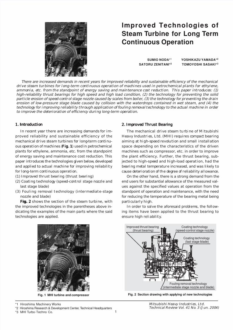
Fig. 2Fig. 2Fig. 2Fig. 2Fig. 2 shows the sect ion of th e stea m tu rbine, wi th
the improved technologies in t he pa rent heses a bove in-
dicat ing th e examples of the main pa r ts wh ere the sa id
technologies ar e applied.
2. Improved Thrus t Bear ing2. Improved Thru s t Bear ing2. Improved Thrus t Bear ing2. Improved Thru s t Bear ing2. Improved Thru s t Bear ing
The mechan ica l dr ive s t eam tu rb ine of Mi t subi sh i
Heavy Industries, Ltd. (MHI) requires compact bearing
aiming at high-speed revolut ion and sma l l insta l lat ion
space depending on the charac ter i s t i cs of the dr iven
ma chines su ch as compr essor, etc. in order to improve
the p lant e ffi ci ency. Fur ther , t he t hru s t bea r ing , sub-
jected t o high-speed a nd h igh- load operat ion, ha d th e
bear ing metal tempera tur e increased, and wa s l ikely to
cause d eter iora tion of th e degree of reliability allowance.On the other ha nd, there i s a st rong demand from the
end user s for substa ntia l al lowan ce of the m easu red val-
ues against the speci f ied values at operat ion f rom the
stan dpoint of operat ion and maintena nce, wi th t he n eed
for redu cing the tem pera tu re of th e bearing meta l being
par t icular ly high.
In order to solve th e aforesaid p roblems, th e follow-
i ng it em s ha ve been app l i ed t o t he t h r u s t bea r i ng t o
ensu re high r eliabili ty.
Fig. 1 MHI turbine and compressor Fig. 2 Section drawing with applying of new technologies
Improved thrust bearing
(thrust bearing)
Coating technology
(speed-control stage nozzle)
Coating technology(last stage blade)
Fouling removal technology
(intermediate stage nozzle and blade)
SUMIO NODA*1
SATORU ZENITANI*2
YOSHIKAZU YAMADA*2
TOMOYOSHI SASAKI*3
*1 Hiroshima Machinery Works
*2 Hiroshima Research & Development Center, Technical Headquarters
*3 MHI Turbo-Techno Co.
5/9/2018 MHI Improved Technology of Steam Turbine - slidepdf.com
http://slidepdf.com/reader/full/mhi-improved-technology-of-steam-turbine 2/5
2
Mitsubishi Heavy Industr ies, Ltd.Technical Review Vol. 41 No. 3 (Ju n. 2004)
(1) Direct lubricatin g system
(2) Imp roved leveler
(3) Pa d ba ck meta l: Chr omium-copper
(4) Offset pivot
2.1 Direct lubr icat ing type2.1 Direct lubr icat ing type2.1 Direct lubr icat ing type2.1 Direct lubr icat ing type2.1 Direct lubr icat ing type
The bearing was conventionally f i l led with lubricat-
ing oi l in order to ma inta in h igh rel iabi l i ty. However,
the weakn ess such as t he problem of t empera tu re r i se
in bearing meta l due to high-tempera tur e lubricatin g oil
of th e upper side pad, th e increas e in bearing loss due to
resistan ce of lubr icat ing oil by st i r r ing at the outer pe-
ripher y of thru st collar , etc. have come to the su rface as
the speed increases.
As a solution to this problem impr ovemen ts were ma de
in th e bear ing chara cter ist ics by adopt ing di rect lubr i -
cating syst em, aimin g at non-flood.
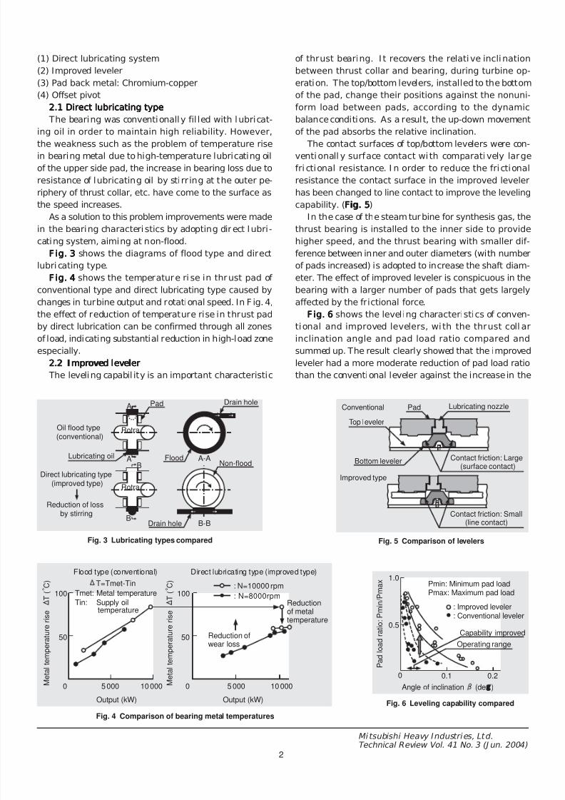
Fig. 3Fig. 3Fig. 3Fig. 3Fig. 3 shows the diagrams of f lood type and di rect
lubricating type.
Fig. 4Fig. 4Fig. 4Fig. 4Fig . 4 shows the t em pera t ure r i se in thru s t pad of convent iona l type and direct lubricating type caused by
changes in turbine output a nd rotat iona l speed. In Fig. 4,
th e effect of redu ction of temp era tu re r ise in th ru st pa d
by direct lubrication can be confirmed th rough a ll zones
of load, indicating su bsta nt ial redu ction in h igh-load zone
especially.
2.2 Impr oved leveler2.2 Impr oved leveler2.2 Impr oved leveler2.2 Impr oved leveler2.2 Impr oved leveler
The leveling capa bility is an importa nt cha ra cterist ic
of th ru st bear in g. I t recovers the relat ive incl inat ion
between thru s t col la r and bear ing , dur ing turb ine op-
erat ion. The top/bottom levelers, inst alled to the bottom
of the pa d , chan ge the i r pos it ions a gains t t h e nonun i -
f o r m l oad be t w een pads , a cco r d i ng t o t he dynam i c
balan ce conditions. As a resu lt , the up-down movement
of the pad absorbs the relative inclination.
The conta ct su rfaces of top/bott om levelers were con-
vent ional ly sur f ace contac t wi th compa ra t ive ly l a rge
fr ict ional resistance. In order to reduce the f r ict ional
resist an ce the cont act su rface in th e improved leveler
ha s been cha nged to l ine cont act to improve the leveling
capa bility. (Fig. 5Fig. 5Fig. 5Fig. 5Fig. 5)
In th e case of th e steam t ur bine for synthesis gas, the
th ru st bear ing is insta l led to the inner side to provide
higher speed , and the t hru s t bear ing wi th smal l er d i f-
ference between inner a nd outer diameter s (with nu mber
of pads increa sed) is adopted to increase th e sha ft diam -
eter. The e ffect of impr oved leveler is conspicuous in t hebear ing wi th a larger nu mber of pads th at gets largely
affected by the frictional force.
Fig. 6Fig. 6Fig. 6Fig. 6Fig. 6 sh ows the leveling char acter ist ics of conven-
t i ona l and i m pr oved l eve le r s , w i t h t he t h r u s t col la r
i nc l i na t i on ang l e and pad l oad r a t i o com par ed and
summ ed up. The result clearly showed tha t th e improved
leveler ha d a more modera te redu ction of pad load ra tio
th an t he conventional leveler against th e increase in the
A
A A-A
B
B
B-B
Fig. 3 Lubricating types compared
Oil flood type(conventional)
Lubricating oil
Direct lubricating type(improved type)
Reduction of lossby stirring
Pad
Drain hole
Drain hole
Flood
Rotra
Rotra
Non-flood
100
50
0 5000 10000
100
50
0 5000 10000
Tmet: Metal temperature
Tin: Supply oiltemperature
T=Tmet-Tin : N=10000 rpm
: N=8000rpm
Fig. 4 Comparison of bearing metal temperatures
M e t a l t e m p e r a t u r e r i s e
T ( o C )
M e t a l t e m p e r a t u r e r i s e
T ( o C )
Flood type (conventional) Direct lubricating type (improved type)
Output (kW) Output (kW)
Reductionof metaltemperature
Reduction ofwear loss
Fig. 5 Comparison of levelers
Conventional
Improved type
Top leveler
Bottom leveler
Pad Lubricating nozzle
Contact friction: Large(surface contact)
Contact friction: Small(line contact)
Fig. 6 Leveling capability compared
0 0.1 0.2
1.0
0.5
P a d l o a d r a t i o : P m i n / P m a x Pmin: Minimum pad load
Pmax: Maximum pad load
: Improved leveler: Conventional leveler
Capability improved
Operating range
Angle of inclination (de )

5/9/2018 MHI Improved Technology of Steam Turbine - slidepdf.com
http://slidepdf.com/reader/full/mhi-improved-technology-of-steam-turbine 3/5
Mitsubishi Heavy Industr ies, Ltd.Technical Review Vol. 41 No. 3 (J un . 2004)
3
angle of inclinat ion, ensu ring dra stic improvement in th e
leveling capability.
2.3 Pad back m etal : Chromium-copper2.3 Pad back met al : Chromium-copper2.3 Pad back m etal : Chromium-copper2.3 Pad back met al : Chromium-copper2.3 Pad back met al : Chromium-copper
Convent ional ly steel is adopted a s th e back meta l of
bear ing pad. However , the impr ovement of the th erma l
conductivity of bearing pa d can be considered a s a mean s
to reduce the bear ing temperatu re.
The adoption of chromium-copper with high thermal
condu ct ivity i s expected to reduce the t emper at ur e by
10 to 15oC as compar ed wi th th e steel bear ing (Fig. 7Fig. 7Fig. 7Fig. 7Fig. 7).
2.4 Offset pivot2.4 Offset pivot2.4 Offset pivot2.4 Offset pivot2.4 Offset pivot
The bear ing temper at ure can be redu ced by improv-
ing the load capaci ty of the bear ing. The offset pivot
ma kin g positive use of th e wedge effect of oil film can be
a good mean s to this regard.
The effect is shown in Fig. 8Fig. 8Fig. 8Fig. 8Fig. 8
3. Coat ing Techn ology3. Coat ing Techn ology3. Coat ing Techn ology3. Coat ing Techn ology3. Coat ing Techn ology
The following two can be considered a s th e ma in ageddeter iorat ions of steam turbine dur ing long- term con-
t inuous operat ion.
(1) Solid par ticle erosion of speed -contr ol sta ge nozzle
cau sed by sca les from th e boiler (iron oxide, silica, et c.)
(2) Dra in erosion of low-press ur e sta ge blade caus ed by
collision with wa ter drops un der high-speed revolution
in wet steam including waterdr ops
Accordingly, prevention of the aforesaid erosions is
vital to achievement of long-term cont inuous operation,
an d is extrem ely importan t for prevent ing deterioration
of the t urbine. Fig. 9Fig. 9Fig. 9Fig. 9Fig. 9 shows an e xam ple of erosion pre-
ventin g technology adopted by MHI.
Here, s tel l i te cladding by plasma t ra nsfer ar c weld-
i n g i s i n t r o d u c e d a s a n e x a m p l e o f d r a i n e r o s i o n
p r even t i ng t echno logy fo r t he l a s t s t age b l ade , and
boronize t r ea t ment as a n exam ple of par t i c le e ros ion
prevent ing t echnology for speed-control st age n ozzle.
The st el l ite cladding by plasm a a rc welding wi l l be
called herea fter as PTA stell i te cladding.
3.1 PTA stell i te cladd ing3.1 PTA stell i te claddin g3.1 PTA stell i te cladd ing3.1 PTA stell i te claddin g3.1 PTA stell i te claddin g
In th i s method the s t e l li t e powder i s suppl i ed in to
t h e p l a s m a a r c ge n e r a t e d b e t w e en p l a s m a w e l d i n g
torch a nd ba se meta l (b l ade) to be mel t ed an d welded,
an d opt imiza t ion of weld ing condi t ions together wi th
robot ic welding en sur es st eady h igh-qua l i ty clad- layer
wi th less mel t in g of th e bas e met al ( i .e . wi th low dilu-
t i on r a t e ) e v e n a t t h e t h i n a n d e a s y - t o-m e l t e d g e
sect ion of th e blade end. Fur t her , this meth od ha s lessw e l d ing de f or m a t i on an d does no t need w e l d d i s t o r -
t ion rem oving, etc.
Fig. 10Fig. 10Fig. 10Fig. 10Fig. 10 shows th e appear an ce of th e blade applying
PTA stel l ite cladding compa red wi th the appea ran ce of
the blade applying the conventional stell i te plate st ick-
ing by s i lver a l loy braz ing . Unl ike the s t e l l i t e p l a t e
st icking by si lver a l loy bra zing, the PTA stel l i te clad-
d ing provides smooth , cont inuous an d in t egra l shape
almost undist inguishable from the blade base m etal .
120
100
80
60
40
20
02 000 4 000 6 000 8 000 10 000
10-15oC
: STEEL: Chromium-copper
P=20 k f/cm2
P=20k f/cm2
Fig. 7 Back metal material compared
C a l c u l a t e d v a l u e o f
m e t a l t e m p e r a t u r e ( o C ) Temperature reducing effect
Rotational speed (rpm)
120
110
100
90
80
70
600 2 4 6 8 10 12
SPEED: N=11300 rpmLOAD: W=4800 k f
OFF SET: e=100 XL
L/2 L/2
Fig. 8 Offset ratio compared
M e t a l t e m p e r a t u r e
( c a l c u l a t e d v a l u e ) ( o C )
: Maximum metal temperature
Temperaturereduced
Offset ratio e (%)
Calculating conditions
Pad Pivot
Silver brazing(conventional technique)
After welding Completed product Completed product
Stellite sectiontellite se ction
Stellite section
Stellite platetellite p late
Stellite plate
Silver brazingSilver brazingilver brazing
Silver brazing
Fig. 10 Stellite appearance compared
PTA stellite cladding
Fig. 9 Erosion prevention
ItemSolid particle
erosionDrain erosion
Temperaturecondition
High Low
Coatingtechnology
.Boronizing
.Plasma spraying
.Plasma spraying
.Stellite plate stickingby silver alloy brazing
.PTA stellite cladding
Applied section Nozzle Blade

5/9/2018 MHI Improved Technology of Steam Turbine - slidepdf.com
http://slidepdf.com/reader/full/mhi-improved-technology-of-steam-turbine 4/5
Mitsubishi Heavy Industr ies, Ltd.Technical Review Vol. 41 No. 3 (Ju n. 2004)
4
Fig. 1Fig. 1Fig. 1Fig. 1Fig. 111111 shows th e erosion r esistan ce of PTA meas ured
from th e cavita tion an d erosion tes ts condu cted accord-
ing t o ASTM G32-77 (environm ent : ion-excha nge wat er,
t emper a tu re : room tempera tur e , t es t fr equen cy: 18 .3
kHz, t es t -p iece end ampl i tude: 25 u m) and compa red
with si lver brazing, indicating th at t he PTA ha s th e ero-
sion resistance equivalent to that of si lver brazing.
F igF igF igF igF ig ..... 1212121212 shows the fat igue st rength of PTA evaluat ed
by using Ono-type rotat ing bending fat igue test (envi-
ronment : atmosphere, temperatu re: room tempera tur e,
frequency: 60 Hz) and compa red with si lver br azing, in-
d i ca t i n g t h a t P TA h a s e x ce l le n t fa t i g u e s t r e n g t h
cha r a c t e r i s t i cs w h i l e s il ver b r a z i ng has t he f a t i gue
stren gth r educed approximately to half of the base m etal .
In v i ew of th e aforesa id poin t s , t h e pro tec ted area
(stell ite section) in conven tional met hod was l imited t o
th e blade t ip. In th e case of PTA, however, since the fa-
t igue st rength equivalent to that of the base m etal can
be obta ined , th e weld ing i s poss ible up to th e cent r a lpor t ion of the blade. Thu s, with t he protected ar ea ex-
pan ded, app licat ion of PTA is expected to get expa nded
to str ict erosive environmen t. Fur th er, th e stell ite plate
ha d problems such a s di f ficul ty in m olding an d neces-
s i ty of manu al work , whereas in the case of PTA, the
welding is car ried out mechan ically, bringing a bout con-
siderable improvement in qua l ity a nd yield.
3.2 Boronizing3.2 Boronizing3.2 Boronizing3.2 Boronizing3.2 Boronizing
The boronize trea tmen t applied to the a ctual machine
as a t echnology to prevent pa rt icle erosion on speed-con-
t r ol stage nozzle cau sed by scales f rom th e boiler , i s a
sur face hardening technology and has th e treat ing meth-
ods and cha ra cterist ics as given below.
(1) Treatin g meth ods.Forma tion of high-har dness boron a lloy layer (Fe2B).Penetr ated di ffusion t reatm ent
(2) Cha ra cterist ics
.En sur es boron a lloy layer of ha rdn ess Hv 1200
-
1800
.H i gh ha r dness a t h i gh t em per a t u r e and exce l l en t
hardwear ing proper t ies at high temperature.High break a way resistance because of penetra tion int o
the base meta l.Thin layer (appr oximat ely 80 u m) of boron a lloy
Fig. 13Fig. 13Fig. 13Fig. 13Fig. 13 shows the m echanism of nozzle wear da ma ge.
The scale is generat ed and grows into the inner sur-
f ace o f t he bo i l e r t ube due t o s t eam ox i da t i on ; t he
enlarged scale then gets break away because of the weak-
ening of i t s adh erence to the base met al of th e tube at
th e t ime of sta rt /stop of th e plant before finding i ts wayinto the turbine.
Since the f low direct ion whi le passing through the
nozzle profile gets sh ar ply cha nged, the scale with lar ger
specific gra vity fails to catch up with t he s tea m flow be-
caus e of th e effect of iner tia a nd get s coll ided with th e
nozzle prof i le , causing wear damage. This i s what we
call solid par ticle er osion. Pa rticularly t he speed-control
sta ge nozzles insta l led at t he inlet of th e tur bine have
larger damage.
Fig. 14Fig. 14Fig. 14Fig. 14Fig. 14 shows the t est r esul ts of resista nce to sol id
Fig. 13 Mechanism of nozzle wear damage
Damage
Nozzle profile
: Steam flow
: Scale
0
-0.5
-1
-1.50 10 20 30
Fig. 14 Solid particle erosion test compared
D i m e n s i o n l e s s
w e i g h t l o s s
Reduction ofthickness loss
Boronizetreatment
Base metal only
Test time (Hr)
0
-0.5
-1
-1.5
-2
-2.5
-30 1 2 3 4 5 6 7 8 9 10
Fig. 11 Erosion resistance
W e i g h t l o s s ( m
) : Base metal only: Stellite plate sticking by silver alloy brazing: PTA stellite cladding
Test time (Hr)
1.2
1.0
0.8
0.6
0.4
0.2
0105 106 107
Number of cycles
Fig. 12 Fatigue strength
D i m e n s i o n l e s s
s t r e s s a m p l i t u d e
: Base metal: Stellite plate sticking by silver alloy brazing: PTA stellite cladding
Fatigue limit of base metal
Silver brazing(conventional technique)
Improved

5/9/2018 MHI Improved Technology of Steam Turbine - slidepdf.com
http://slidepdf.com/reader/full/mhi-improved-technology-of-steam-turbine 5/5
Mitsubishi Heavy Industr ies, Ltd.Technical Review Vol. 41 No. 3 (Ju n. 2004)
5
par ticle erosion with or without boronize trea tmen t, in-
d ica t ing tha t t he wear loss of the nozzle subjected t o
boronizing is extremely less th an th at of the nozzle with-
out boronize t rea tm ent . For exam ple, th e wear loss of
the nozzle subjected to boronizing a fter a 10-hour test is
appr oximat ely one-tent h of the nozzle with out boronize
t r ea tment .
Fig. 15Fig. 15Fig. 15Fig. 15Fig. 15 shows the a ppeara nce of the a ctual speed-con-
trol sta ge nozzle su bjected to boronizing compa red with
the a ppeara nce of the nozzle without boronize trea tment .
The dam age i s c lear ly v i s ib l e a t t he out l e t en d of the
nozzle without boronize treat men t, which is not seen in
the nozzle with boronize treat ment , indicat ing th e effec-
t iveness of surface harden ing t reatm ent .
4. Fouling Rem oval Technology4. Fouling Rem oval Technology4. Fouling Rem oval Technology4. Fouling Rem oval Technology4. Fouling Rem oval Technology
Stea m tu rb ines su bjec ted to long-t erm cont inuous
operat ion ha ve the du st (di r t ) accumulated in t he blade
an d nozzle, cau sing fouling problems such a s deter iora -tion of performa nce an d efficiency, etc. Pat ent ha s a lready
been appl i ed for a n onl ine washing met hod as a so lu-
t ion, where water i s fed into the va lve cha mber of the
extract ion contr ol valve dur ing n ormal operat ion to re-
duce the steam temperatu re and t o increase the wetness
of stea m without h aving to reduce the plant load or to
stop the tu rbine. The method has a lready been confirmed
appl i cable to actua l machine through t es t s us ing ma -
chines equivalent to the a ctual ones, wi th th e ef fect on
actual m achine being un der conf irma t ion.
5. Conclusion5. Conclusion5. Conclusion5. Conclusion5. Conclusion
With t he recent t rend of energy-saving and redu ction
of maintenance cost , the sustainable ef f iciency of the
machines for long- term cont inuous operat ion through
improved reliabili ty a nd achievement of fouling r emovaltechnology is an impor ta nt problem for t he futur e.
MHI i s ma king a l l e ffor t s t o develop t echnologies
t o r e spond t o such needs a nd t o app l y t hem t o act ua l
machines .
In order t o react an d respond positively to the n eeds of
end us ers rega rding long-term cont inuous operat ion, it is
indispensable to carry out research and development of
high-reliability techn ologies. MHI is d eter mined to coop-
era t e wi th other r e l a t ed r esearch ins t i tu t es for t imely
application of such technologies to actual machines.
Fig. 15 Appearance of speed-control stage nozzle compared
W e a r d e g r e e Wear pattern image
: Base metal only
: Boronize treatment
ErosionOperating time
Base metal only (without treatment) Boronize treatment
Sumio Noda Yoshikazu Yamada Satoru Zenitani Tomoyoshi Sasaki