mice tracker readout status vlpc – cryo – front end electronics a.bross berkeley, february 2005
TRANSCRIPT

MICE Tracker Readout Status
VLPC – Cryo – Front End ElectronicsA. Bross
Berkeley, February 2005

Analog Front End Board for VLPC Readout
9o KVLPC
(x512)
AFE
DISCR ADCDiscriminator output every 396 nsec for L1
Amplitude signal readout for L3 and offline
8 photons
50 fC
Central Fiber Tracker cylinder

First AFEII prototype is now on the cryostat and taking data.
Next 4 slides show the AFEI problems that AFEII is designed to solve:
SVX saturation. SVX tick to tick ped variation. DISCR to SVX data cross talk.
AFEII prototypes
AFEII proto: Results
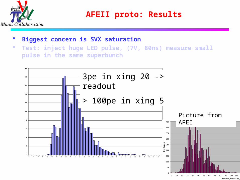
Biggest concern is SVX saturation Test: inject huge LED pulse, (7V, 80ns) measure small pulse
in the same superbunch
3pe in xing 20 -> readout
> 100pe in xing 5
0
50
100
150
200
250
300
350
400
450
1 10 19 28 37 46 55 64 73 82 91 100 109 118 127 136 145 154 163 172 181 190 199 208 217 226 235 244 253
Bond=1, Ave=44.33, StdDev=15.58, Discriminator Counts=0
Bin
Co
un
ts
Picture from AFEI

AFEII proto: Results
Tick to tick variation in pedestals. Reset is identical every xing, so there is none.
The sum of data from xing 5, 8, 11 , 14 , 17 , 20 all 64ch from module 1
PMR: I included the individual xing plots in spare slides section, if you wish to check in more detail.

AFEII proto: Results
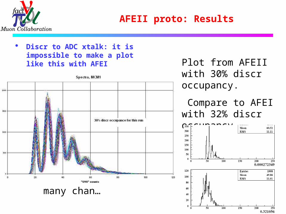
Discr to ADC xtalk: it is impossible to make a plot like this with AFEI
Plot from AFEII with 30% discr occupancy.
Compare to AFEI with 32% discr occupancy
one chan…
AFEII proto: Results
Discr to ADC xtalk: it is impossible to make a plot like this with AFEI Plot from AFEII with
30% discr occupancy.
Compare to AFEI with 32% discr occupancy
many chan…

4) AFEII-t design
Was on hold until AFEII prototype was up– now starting integrate lessons from AFEII prototypes.
Stefano Rapisarda is joining this effort.

AFE II/AFEIIt Status
Recently concluded Dzero internal review awaiting report/recommendations of the committee
Progress on a number of fronts:
1. AFEII on the cryostat and taking data. (same cass. as used for AFEI studies by Juan and Peter)
2. Better understanding of TriP-t, studies in progress, needed manpower now on board.
3. AFEII-t engineering help identified and on board.

Trigger Pipeline Chip with Time Stamp
Tript

Currents to opamps, switch settings, feedback settings set with on-chip DACsTo date, parameters are based on what worked on the TRIP chipAdjustment of these parameters could improve performance further
200f
1.5p
4.0p

Digital (DISC) out

Saturation occurs ~130fC; expected at ~90fC
Residual seems related to DC level of ~40mV which also appears on T_OUT. Suspicion rests upon output drivers to analog pipeline
Chip designer has recently suggested a “parameter” change that he believes will help
Might make identification of individual p.e. peaks harder (?)
Noise is ~3mV Gaussian, shown as error bars on plot and is the same for the T_OUT line
16 Channel Average
0
20
40
60
80
100
120
0 20 40 60 80 100 120 140
fC
mV
/ 1
0
8 p.e. @ 40k gain 16 p.e.
Residual
-3
-2
-1
0
1
2
3
0 20 40 60 80 100 120 140
fC
mV
/ 1
0
1 p.e.
A-pulse

Does t affect A?
100fC at “Sweet spot”
30fC, 60nsec later

Does t affect A?
Existence of analog time-info pulse lowers the analog amplitude-info pulse by 3 1/2 ~ 4 % of the size of the time-info pulse
Same if time-info pulse lowered by changing the actual time or by changingthe current integrated to measure the time
Ratio of pulses from adjacent fibers with similar time data sees smaller effect than individual pulses will

Pulse Time (T_OUT)Channel 13
0
250
500
750
1000
1250
-50 0 50 100 150ns
Time Measured vs Generated 9.7 mV/nsec
Adjustment of currentthrough integrating circuitpermits gains ranging from~2 to ~20 mV/ns
t-pulse
mV

Time Walk
t / Q 0.40 mV/fC, corresponding to 44 ps/fC
• T_OUT has large pulse-to-pulse fluctuations below ~20fC 2 p.e. @40k gain over threshold
• Digital discriminator set to fire ~4f in this test
• Only been able to look carefully at 2 channels so far, but they are similar
Channel 13
600
650
700
750
800
0.0 20.0 40.0 60.0 80.0fC Injected
mV
0.0%
25.0%
50.0%
75.0%
100.0%
T_OUT (mV)
Trigger (%)
Noisy Data
A MIP at 90 corresponds to about 50fC(8 photoelectrons collected)

What Happens Next
Impact of A-pulse nonlinearity should be quantitatively assessed, should test with “parameter” change not solve the problem
Chip order in early March will probably be submitted with multiple versions, so it would be prudent to have older pipeline output driver, or other redesign, as one of them - should not impact schedule
Further probing of parameter space will provide info re. optimal running conditions
Documentation needed

TriPt - Conclusions
TriP-t is fully fuctional and basically performs as expected
Answers to specific questions: t-info pulse lowers A-info pulse 3 ½ ~ 4% of t-pulse;
effect on A ratio in adjacent fibers ought to be even smaller
Time pulse gain setable from 2 ~20 mV/ns Time output walk ~44 ps/fC for pulses with ~2 or
more p.e.
Further work is warranted for: A-pulse nonlinearity Optimization of parameter space Documentation

LVSB Board
VME LVDS SERDES Buffer(Serializer-Deserializer)
VME LVDS SERDES Buffer (VLSB)
The D0/MICE VME64 LVDS SERDES Buffer (D0 VLSB) is a VME64 single wide 6U module SERDES (SERializer-DESerializer)
It can be used for Read out and testing the AFEII boards. The module is a custom LVDS
SERDES Buffer with 4 LVDS inputs channels and can be operated stand-alone with minimal additional hardware.
The design allows system expansion to multiple modules. A D0 VLSB module can receive/generate trigger signals
over two Lemo connectors on the module front panel. A normal test system configuration consist of a VME 64
subrack where slot 1 is occupied by a VME subrack controller and the D0 VLSB cards will occupy one or more of the remaining slots.

VME LVDS SERDES Buffer (VLSB)
The Boards (6) are now complete and ready for test and integration into the MICE DAQ system (KEK and final system if we choose to do so)


VLSB System Architecture
The VLSB standalone system can be expanded to a set of several cards hosted by 6U VME64Xsubrack.
In this case, the cards can be individually accessed though their RS-232 interfaces. A set of four module can be synchronized through the use of the front panel board-to-board connectors.
All cards in the system can be accessed through a VME subrack controller that can be hosted in the subrack slot 1. This controller can provide the VLSB cards with additional interfaces to the outside world (Ethernet, MIL-STD 1553, ...).

Board Block Diagram

VLSB – AFEIIt Interface

Data Rate Capabilities
Roughly 200 MB/sec per LSVB board VME64X standard transfer speed - to 160 Mbytes/sec. With chosen FPGA, for MICE this system should
accommodate muon rates up to 1000 per RF flat top.

VLPC Cryo Status
Cryo-Cooler Version

Preliminary fit up - good

Status Summary
Real assembly should start this week. Many miscellaneous parts ordered and most
here. (o-rings, bolts, cryo grease, fittings, copper strips)
Compressor for Cryo cooler wired up. Extending control cables.
Run Cryo cooler only – week of 2/21? Cool cassettes – week of 2/28 or later? Ship in March

Pictures – Assembly stand
Issues still to address
Control system details Sensors, controllers, heater, feed thru’s
Safety Documents & approval “Pressure vessel” is special Need to size & obtain relief valves
Thermal link fabrication unknowns Temperature & pressure stability
small gas volume part of commissioning/test

Schedule details
Step Status Date
Shipment of parts arrive from Japan Done - Arrived at FNAL Jan. 3
Uncrate, inspect, and inventory parts Done Week of 1/17
Make parts, o-rings, modifications to parts as necessary Making 4 needed parts now Week of 1/17Still need to unsolder copper parts
Fabrication of invar envelopes at FNAL Done Week of 1/17
Write req, send out drgs, fabricate backplane structure Need to do Week of 1/17
Smooth o-ring surfaces on underside of top lid Done Week of 1/17
Order missing/auxilliary items (heaters?,sensors?,o-rings?, reliefs?) Most parts here or on order Week of 1/24thin 0.005" OFHC Copper rolls & solder on order for thermal clamps Need to buy lid heater & temp sensorsSilicon O-rings for envelope due week of 2/7.
Assemble invar envelope and structure to lid Waiting for silicon o-rings: due this week Week of 2/7
Make safety document & request approval to operate Week of 2/7
Pull vacuum on cryostat vacuum jacket - Leak check envelopes 2 weeks behind initial shedule Week of 2/14
Assemble cryocooler into lid, instrument cold end, re-close Week of 2/14
Assemble controllers, and operating control system(s) Week of 2/14
Run cryo cooler, input heat at stages, measure temps Week of 2/21
Open up, load cassettes into envelopes, make thermal links, re-close Week of 2/21
Receive approval to operate cryostat with cassette space > atm
Run cryo cooler cryostat with cassettes, operate cassettes. Week of 2/28
Crate up and ship Mid March