michi: mid-infrared camera high-disperser, & ifu spectrograph
TRANSCRIPT
MICHI:Mid-Infrared Camera
High-disperser,& IFU spectrograph
M. Honda (Kanagawa U),
Y.K. Okamoto (Ibaraki U),
A. Tokunaga (UH), C. Packham (UF)
MICHI team
TMT Science and Instrument WS 2011
March 30, 2011, Victoria BC
MICHI:Mid-Infrared Camera
High-disperser,& IFU spectrograph
TMT Science and Instrument WS 2011
March 30, 2011, Victoria BC
未知 (みち) = “Unknown Things”Instrument for challenge to the unknowns
Outline
A brief history and collaborators
IFU Science cases of TMT/MICHI
Required instrument parameters & uniqueness
Overall current Instrument design & key tech.
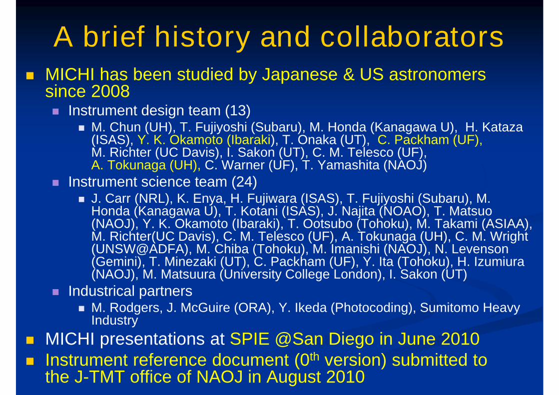
A brief history and collaborators MICHI has been studied by Japanese & US astronomers
since 2008 Instrument design team (13)
M. Chun (UH), T. Fujiyoshi (Subaru), M. Honda (Kanagawa U), H. Kataza(ISAS), Y. K. Okamoto (Ibaraki), T. Onaka (UT), C. Packham (UF),M. Richter (UC Davis), I. Sakon (UT), C. M. Telesco (UF),A. Tokunaga (UH), C. Warner (UF), T. Yamashita (NAOJ)
Instrument science team (24) J. Carr (NRL), K. Enya, H. Fujiwara (ISAS), T. Fujiyoshi (Subaru), M.
Honda (Kanagawa U), T. Kotani (ISAS), J. Najita (NOAO), T. Matsuo(NAOJ), Y. K. Okamoto (Ibaraki), T. Ootsubo (Tohoku), M. Takami (ASIAA),M. Richter(UC Davis), C. M. Telesco (UF), A. Tokunaga (UH), C. M. Wright(UNSW@ADFA), M. Chiba (Tohoku), M. Imanishi (NAOJ), N. Levenson(Gemini), T. Minezaki (UT), C. Packham (UF), Y. Ita (Tohoku), H. Izumiura(NAOJ), M. Matsuura (University College London), I. Sakon (UT)
Industrical partners M. Rodgers, J. McGuire (ORA), Y. Ikeda (Photocoding), Sumitomo Heavy
Industry
MICHI presentations at SPIE @San Diego in June 2010 Instrument reference document (0th version) submitted to
the J-TMT office of NAOJ in August 2010
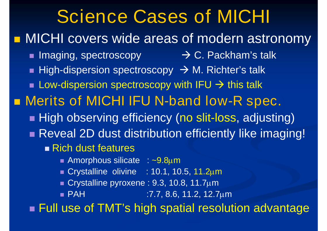
Science Cases of MICHI MICHI covers wide areas of modern astronomy
Imaging, spectroscopy C. Packham’s talk
High-dispersion spectroscopy M. Richter’s talk
Low-dispersion spectroscopy with IFU this talk
Merits of MICHI IFU N-band low-R spec. High observing efficiency (no slit-loss, adjusting)
Reveal 2D dust distribution efficiently like imaging! Rich dust features
Amorphous silicate : ~9.8mm
Crystalline olivine : 10.1, 10.5, 11.2mm
Crystalline pyroxene : 9.3, 10.8, 11.7mm
PAH :7.7, 8.6, 11.2, 12.7mm
Full use of TMT’s high spatial resolution advantage
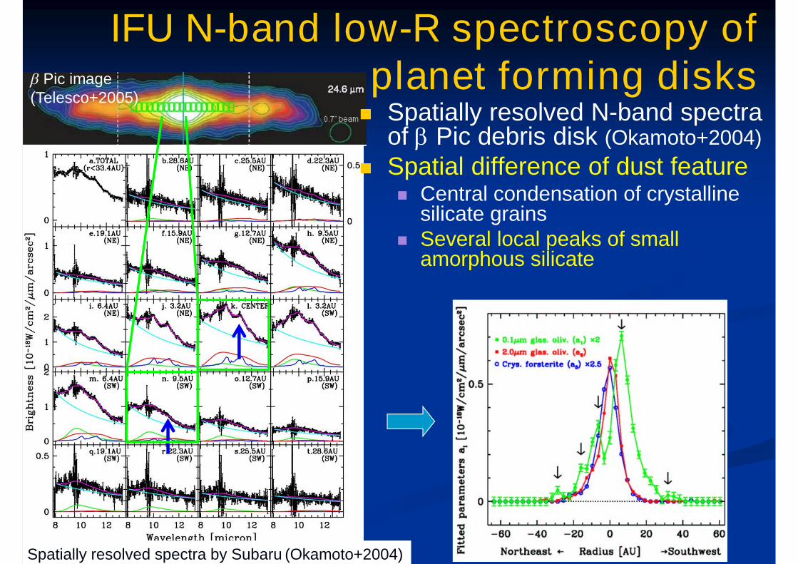
Spatially resolved spectra by Subaru (Okamoto+2004)
IFU N-band low-R spectroscopy ofplanet forming disks Spatially resolved N-band spectra
of b Pic debris disk (Okamoto+2004)
Spatial difference of dust feature Central condensation of crystalline
silicate grains Several local peaks of small
amorphous silicate
b Pic image(Telesco+2005)
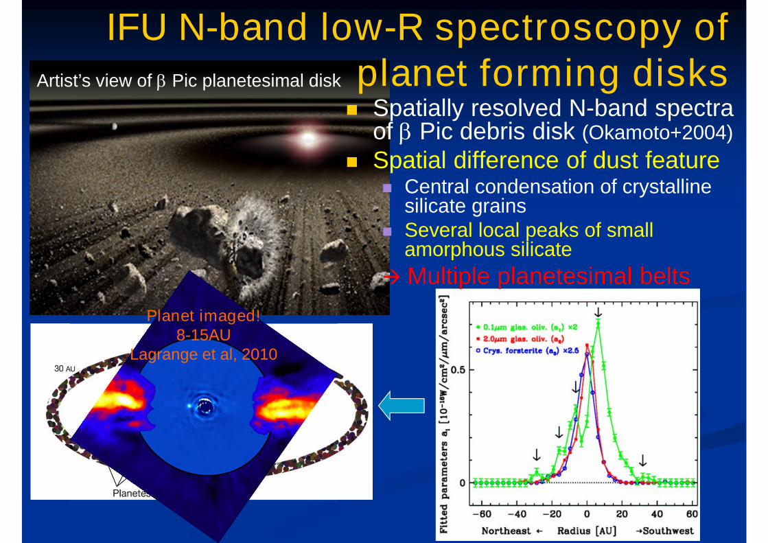
IFU N-band low-R spectroscopy ofplanet forming disks Spatially resolved N-band spectra
of b Pic debris disk (Okamoto+2004)
Spatial difference of dust feature Central condensation of crystalline
silicate grains Several local peaks of small
amorphous silicate
Multiple planetesimal belts
Artist’s view of b Pic planetesimal disk
Planet imaged!8-15AU
Lagrange et al, 2010
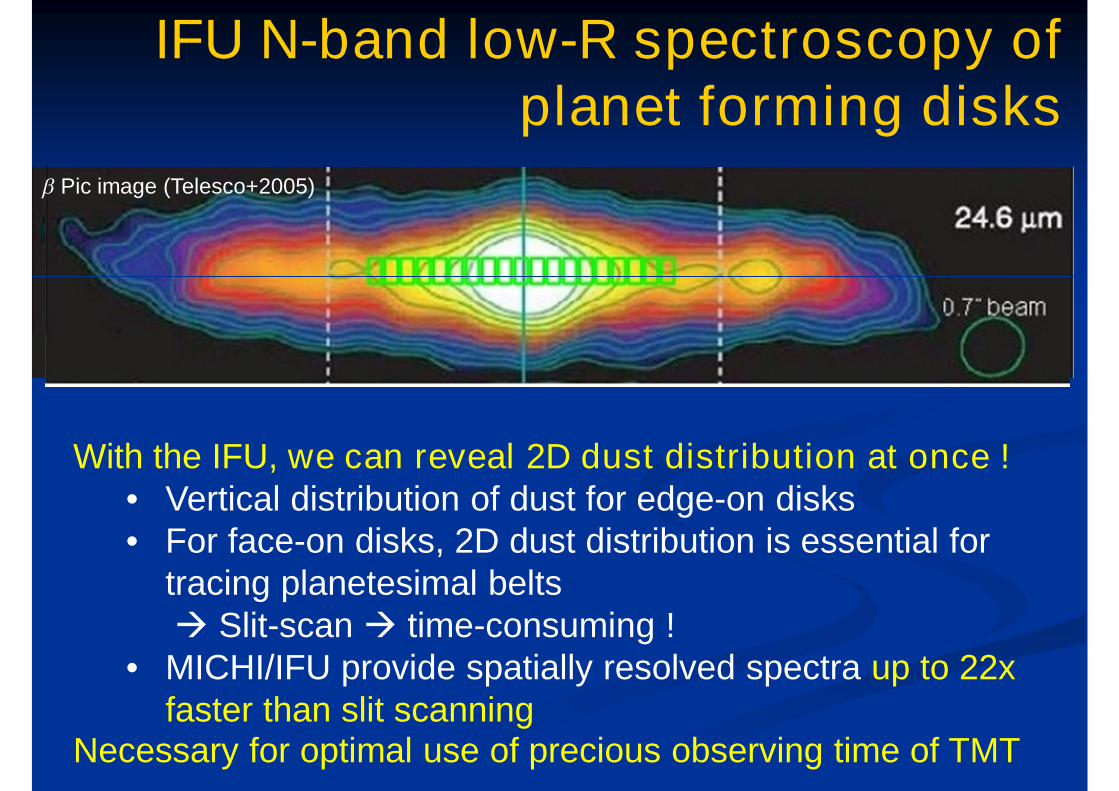
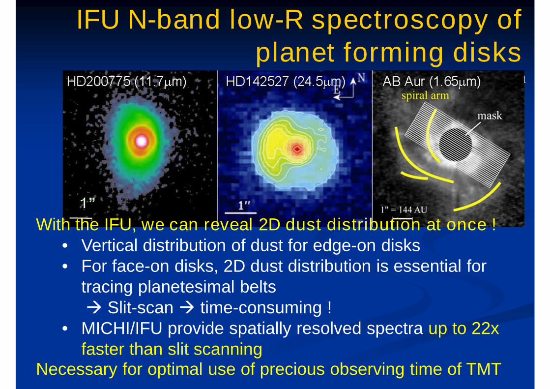
IFU N-band low-R spectroscopy ofplanet forming disks
With the IFU, we can reveal 2D dust distribution at once !• Vertical distribution of dust for edge-on disks• For face-on disks, 2D dust distribution is essential for
tracing planetesimal belts Slit-scan time-consuming !
• MICHI/IFU provide spatially resolved spectra up to 22xfaster than slit scanning
Necessary for optimal use of precious observing time of TMT
b Pic image (Telesco+2005)
IFU N-band low-R spectroscopy ofplanet forming disks Spatially resolved N-band spectra
of b Pic debris disk (Okamoto+2004)
Spatial difference of dust feature Central condensation of crystalline
silicate grains Several local peaks of small
amorphous silicate
Multiple planetesimal belts
With the IFU, we can reveal 2D dust distribution at once !• Vertical distribution of dust for edge-on disks• For face-on disks, 2D dust distribution is essential for
tracing planetesimal belts Slit-scan time-consuming !
• MICHI/IFU provide spatially resolved spectra up to 22xfaster than slit scanning
Necessary for optimal use of precious observing time of TMT
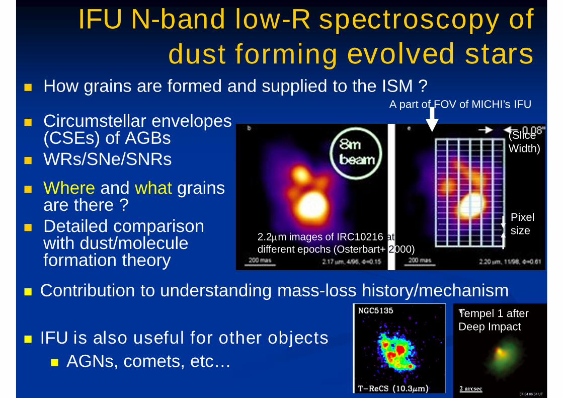
Circumstellar envelopes(CSEs) of AGBs
WRs/SNe/SNRs
2.2mm images of IRC10216 atdifferent epochs (Osterbart+ 2000)
A part of FOV of MICHI’s IFU
Pixelsize
(SliceWidth)
IFU N-band low-R spectroscopy of
dust forming evolved stars How grains are formed and supplied to the ISM ?
Where and what grainsare there ?
Detailed comparisonwith dust/moleculeformation theory
IFU is also useful for other objects
AGNs, comets, etc…
Tempel 1 afterDeep Impact
Contribution to understanding mass-loss history/mechanism
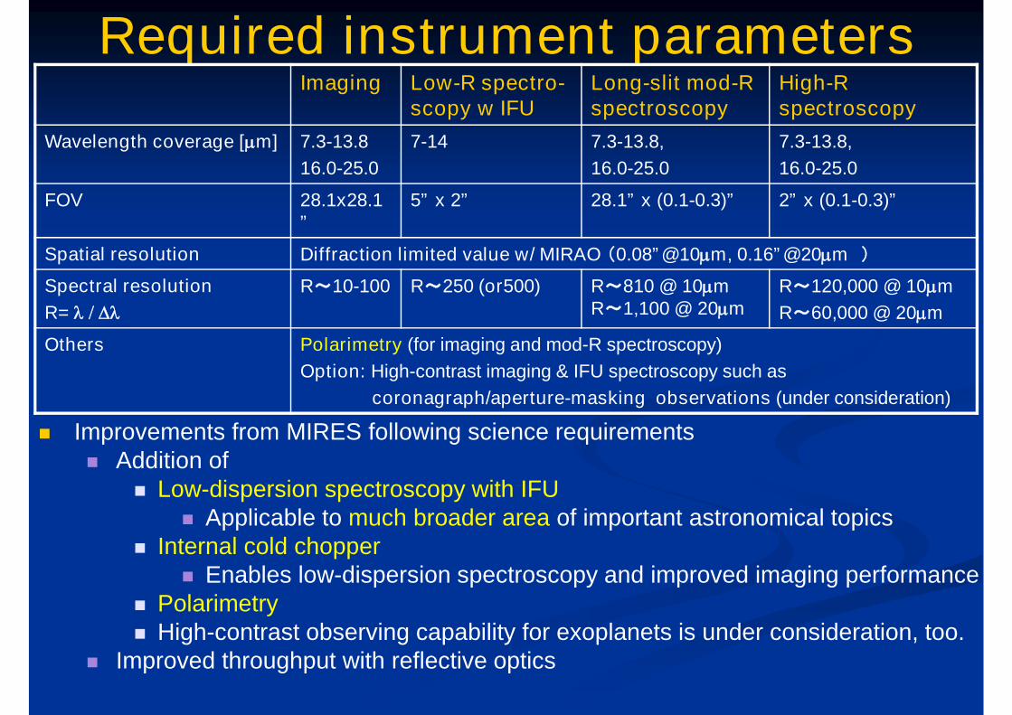
Required instrument parametersImaging Low-R spectro-
scopy w IFULong-slit mod-Rspectroscopy
High-Rspectroscopy
Wavelength coverage [mm] 7.3-13.8
16.0-25.0
7-14 7.3-13.8,
16.0-25.0
7.3-13.8,
16.0-25.0
FOV 28.1x28.1”
5” x 2” 28.1” x (0.1-0.3)” 2” x (0.1-0.3)”
Spatial resolution Diffraction limited value w/ MIRAO (0.08”@10mm, 0.16”@20mm )
Spectral resolution
R= l / Dl
R~10-100 R~250 (or500) R~810 @ 10mmR~1,100 @ 20mm
R~120,000 @ 10mm
R~60,000 @ 20mm
Others Polarimetry (for imaging and mod-R spectroscopy)
Option: High-contrast imaging & IFU spectroscopy such as
coronagraph/aperture-masking observations (under consideration)
Improvements from MIRES following science requirements Addition of
Low-dispersion spectroscopy with IFU Applicable to much broader area of important astronomical topics
Internal cold chopper Enables low-dispersion spectroscopy and improved imaging performance
Polarimetry High-contrast observing capability for exoplanets is under consideration, too.
Improved throughput with reflective optics
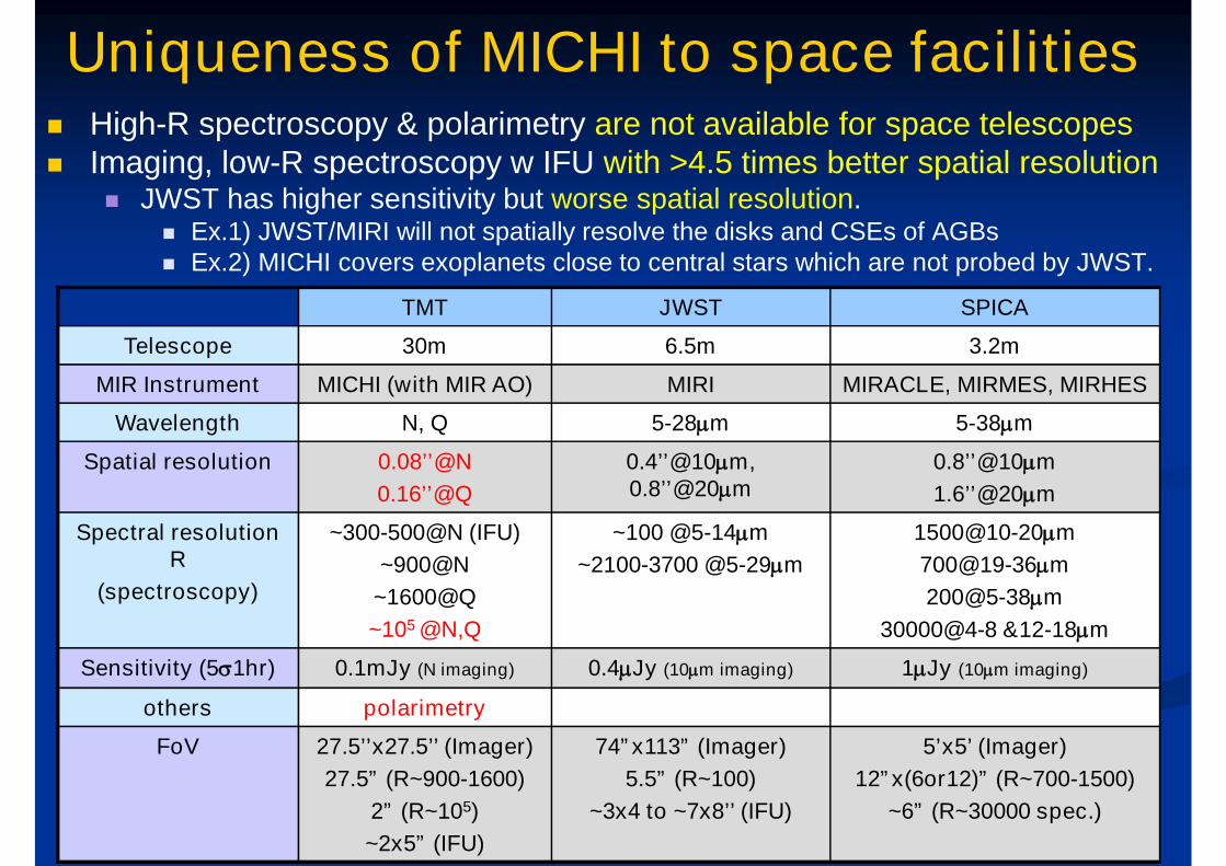
Uniqueness of MICHI to space facilities High-R spectroscopy & polarimetry are not available for space telescopes Imaging, low-R spectroscopy w IFU with >4.5 times better spatial resolution
JWST has higher sensitivity but worse spatial resolution. Ex.1) JWST/MIRI will not spatially resolve the disks and CSEs of AGBs Ex.2) MICHI covers exoplanets close to central stars which are not probed by JWST.
TMT JWST SPICA
Telescope 30m 6.5m 3.2m
MIR Instrument MICHI (with MIR AO) MIRI MIRACLE, MIRMES, MIRHES
Wavelength N, Q 5-28mm 5-38mm
Spatial resolution 0.08’’@N
0.16’’@Q
0.4’’@10mm,0.8’’@20mm
0.8’’@10mm
1.6’’@20mm
Spectral resolutionR
(spectroscopy)
~300-500@N (IFU)
~900@N
~1600@Q
~105 @N,Q
~100 @5-14mm
~2100-3700 @5-29mm
1500@10-20mm
700@19-36mm
200@5-38mm
30000@4-8 &12-18mm
Sensitivity (5s1hr) 0.1mJy (N imaging) 0.4mJy (10mm imaging) 1mJy (10mm imaging)
others polarimetry
FoV 27.5’’x27.5’’ (Imager)
27.5” (R~900-1600)
2” (R~105)
~2x5” (IFU)
74”x113” (Imager)
5.5” (R~100)
~3x4 to ~7x8’’ (IFU)
5’x5’ (Imager)
12”x(6or12)” (R~700-1500)
~6” (R~30000 spec.)
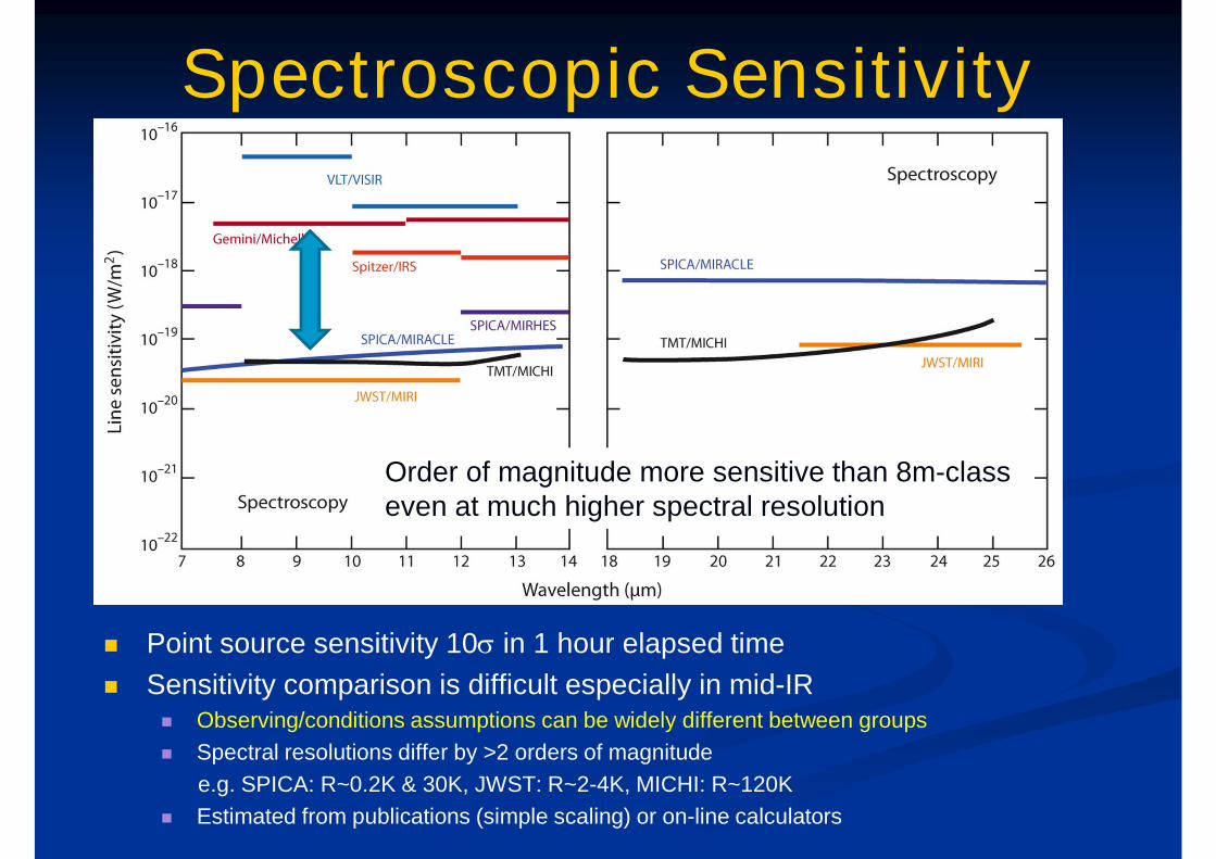
Spectroscopic Sensitivity
Point source sensitivity 10s in 1 hour elapsed time
Sensitivity comparison is difficult especially in mid-IR Observing/conditions assumptions can be widely different between groups
Spectral resolutions differ by >2 orders of magnitude
e.g. SPICA: R~0.2K & 30K, JWST: R~2-4K, MICHI: R~120K
Estimated from publications (simple scaling) or on-line calculators
Order of magnitude more sensitive than 8m-classeven at much higher spectral resolution
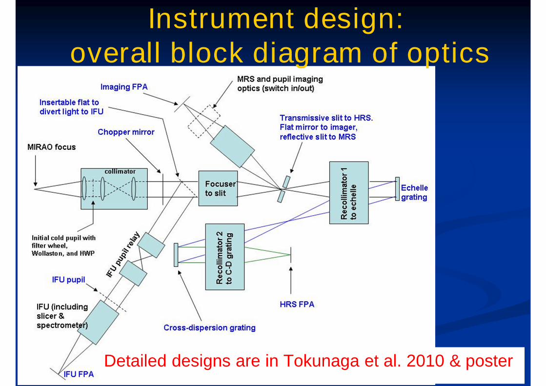
Instrument design:overall block diagram of optics
Detailed designs are in Tokunaga et al. 2010 & poster

Instrument design:overall block diagram of optics
Modular design tomake alignment easier
Fore optics
Imager & mid-dispersionspectrograph
high-dispersionspectrograph
low-dispersionspectrographwith IFU
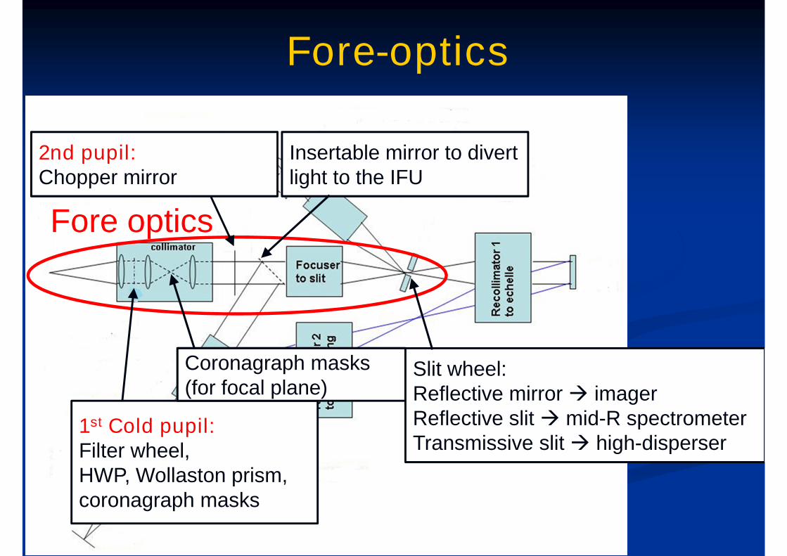
Fore-optics
Fore optics
1st Cold pupil:Filter wheel,HWP, Wollaston prism,coronagraph masks
Coronagraph masks(for focal plane)
2nd pupil:Chopper mirror
Insertable mirror to divertlight to the IFU
Slit wheel:Reflective mirror imagerReflective slit mid-R spectrometerTransmissive slit high-disperser
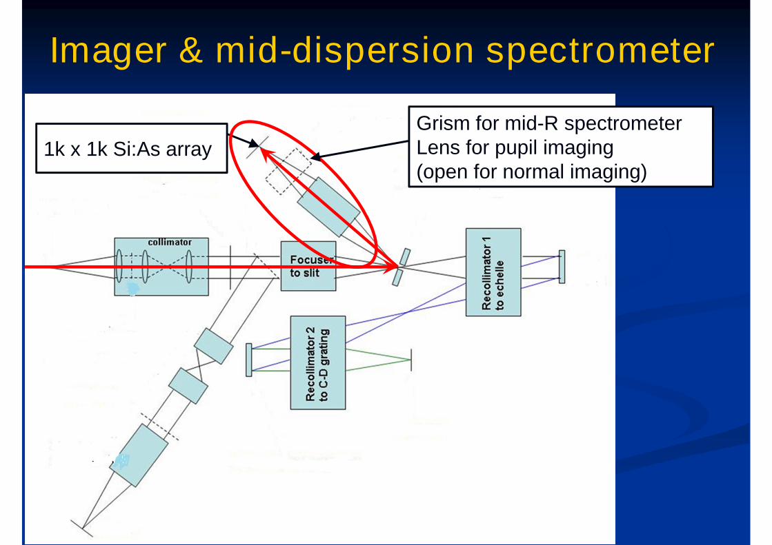
Imager & mid-dispersion spectrometer
1k x 1k Si:As array
Grism for mid-R spectrometerLens for pupil imaging(open for normal imaging)
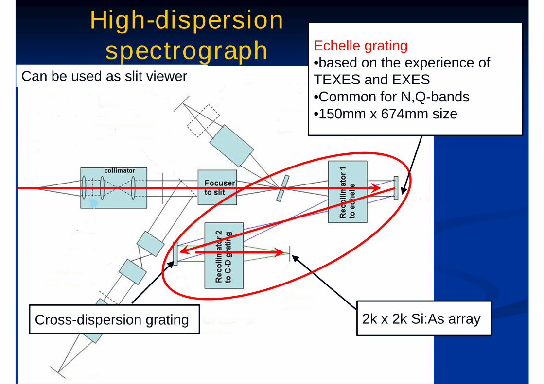
High-dispersionspectrograph
2k x 2k Si:As arrayCross-dispersion grating
Echelle grating•based on the experience ofTEXES and EXES•Common for N,Q-bands•150mm x 674mm size
Can be used as slit viewer
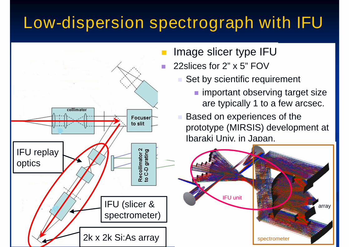
Low-dispersion spectrograph with IFU
2k x 2k Si:As array
IFU replayoptics
IFU (slicer &spectrometer)
Image slicer type IFU 22slices for 2” x 5” FOV
Set by scientific requirement
important observing target sizeare typically 1 to a few arcsec.
Based on experiences of theprototype (MIRSIS) development atIbaraki Univ. in Japan.
array
spectrometer
IFU unit
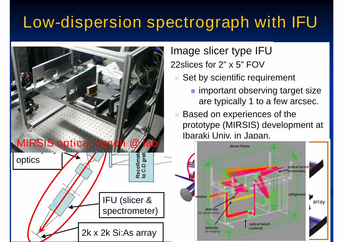
MIRSIS optical bench @ lab
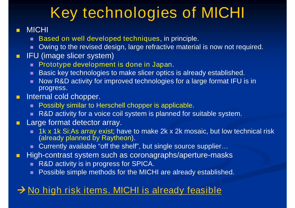
Key technologies of MICHI MICHI
Based on well developed techniques, in principle. Owing to the revised design, large refractive material is now not required.
IFU (image slicer system) Prototype development is done in Japan. Basic key technologies to make slicer optics is already established. Now R&D activity for improved technologies for a large format IFU is in
progress.
Internal cold chopper. Possibly similar to Herschell chopper is applicable. R&D activity for a voice coil system is planned for suitable system.
Large format detector array. 1k x 1k Si:As array exist; have to make 2k x 2k mosaic, but low technical risk
(already planned by Raytheon). Currently available “off the shelf”, but single source supplier…
High-contrast system such as coronagraphs/aperture-masks R&D activity is in progress for SPICA. Possible simple methods for the MICHI are already established.
No high risk items. MICHI is already feasible
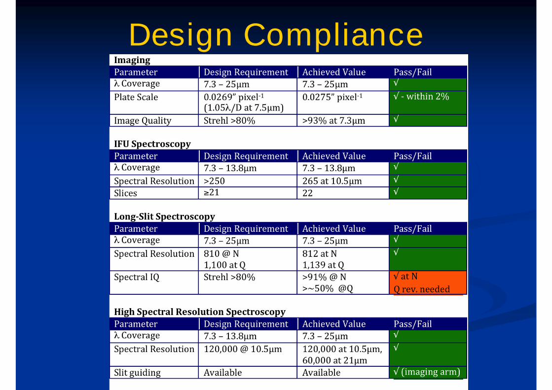
Design Compliance
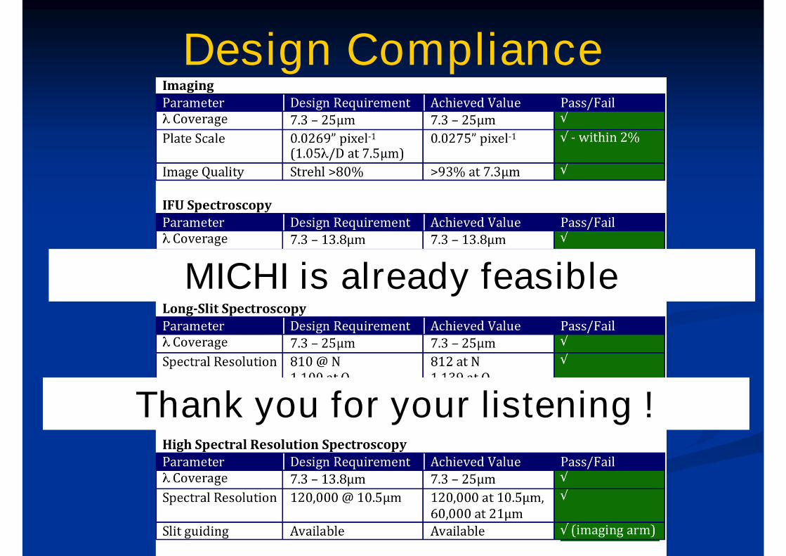
Design Compliance
MICHI is already feasible
Thank you for your listening !