michigan abandoned water well plugging …€¦ · mechanical perforators ... rotary fishing jars...
TRANSCRIPT

MICHIGAN ABANDONED WATER WELL
PLUGGING MANUAL
METHODS
MATERIALS
EQUIPMENT
REQUIREMENTS
Michigan Department of Environmental Quality
Resource Management Division Drinking Water and Environmental Health Section
Environmental Health Programs Unit
APRIL 2012
MICHIGAN ABANDONED WATER WELL PLUGGING MANUAL
by
James S. McEwan, R.S., M.S., Coordinator Abandoned Well Management Program
Environmental Health Programs Unit
April 2012
prepared under Authority of Part 127, 1978 PA 368, as amended, and rules
and published by
Michigan Department of Environmental Quality Resource Management Division
Drinking Water and Environmental Health Section Environmental Health Programs Unit 525 West Allegan, Constitution Hall
P.O. Box 30241 Lansing, Michigan 48909-7741
Additional information on water well construction and the abandoned water well management program may be obtained from the department’s website at
www.michigan.gov/deq.
or you may call 517-241-1377 or fax 517-241-1328
RMD 1001 4/2012

ACKNOWLEDGEMENTS
The author wishes to express sincere thanks to the staff from the Michigan Department of Environmental Quality (DEQ), Resource Management Division, Drinking Water and Environmental Health Section, Mr. Michael S. Gaber, formerly Chief of the DEQ Well Construction Unit and Mr. Brant O. Fisher, DEQ, Environmental Engineer, who provided technical review and guidance during development of the manual. Special thanks to Ms. Anita Ladouceur, Mr. Joseph Crigier, and Ms. Ronda Page, for their editorial critique of the manual; and Ms. Constance Pettis for her clerical review and assistance with formatting. The author wishes to express sincere gratitude to the Michigan Ground Water Association (MGWA) and all the individuals from the water well drilling and service industry that provided photos for, and have contributed to, the development or technical components of this manual. Special thanks to: A & B Webb Enterprises, Inc. - Bob Webb Big Foot Manufacturing - R. Lyle Matteson Central Wells & Pumps, LLC - Bryan Brewer Dyer Well Drilling and Service, Inc. - Mike Dyer Mike Katz Well Drilling - Mike Katz Mike LaLone Well Drilling - Mike LaLone Maurer & Parks Well Drilling, Inc. - Jack and Scott Peru Mid State Oil Tools - Craig Machuta Lee Rich Well Drilling - Lee Rich Terry’s Well Service, Inc. - Terry Cords

i
TABLE OF CONTENTS Acknowledgements ..................................................................................................... ii Table of Contents ........................................................................................................ iii Introduction…………………………………………………………………. ....................... 1 Level of Hazard…………………………………………………………….. ....................... 2 Expected Performance……………………………………………………. ....................... 3 Abandoned Water Well Contamination Examples and Plugging Incidents…… .......... 4 Cooperation Between Water Well Drilling Contractors, Local Health Departments, Communities, and State Agencies……………………… ........................ 8 Preparing an Abandoned Water Well for Proper Plugging ……………………. .......... 10 Plugging an Open Annulus ............................................................................. 10 Perforating Water Well Casings ………………………………………….. ......... 10 Mechanical Perforators ................................................................................... 10 Casing Perforation Using Directed Explosive Charges ................................... 11 Addressing Water Well Casing Damage ........................................................ 12 Fishing Tool String Alignment ......................................................................... 12 Abandoned Water Well Depth. ....................................................................... 13 Procedures for Plugging Water Wells Under Normal Conditions .............................. 14 Plugging Material Volume Calculations .......................................................... 14 Procedures for Plugging Water Wells Terminated in Fractured Rock ....................... 15 Plugging Procedures Near Active Water Wells ............................................... 16 Plugging Procedures for Flowing Water Wells and Break-outs ................................. 18 Pumping Cement at High Pressure ................................................................ 18 Equalizing the Head Pressure ........................................................................ 18 Packers and Plugs .......................................................................................... 19 Plugging Inaccessible Abandoned Water Wells ........................................................ 21 Reverse Flow Sealing ..................................................................................... 21 Plugging Small Diameter Abandoned Water Wells ................................................... 23 Plugging Large Diameter Abandoned Water Wells ................................................... 24 Water Line Extension Sites ....................................................................................... 26 The Importance of Removing Obstructions ............................................................... 27 Water Wells Terminated in Bedrock ............................................................... 27 Screened Water Wells .................................................................................... 28
ii
Selecting an Obstruction Removal Method ............................................................... 29 Obstruction Identification Aids. .................................................................................. 30 Down Hole Video Camera .............................................................................. 30 Impression Blocks. ......................................................................................... 31 Equipment Used for Obstruction Removal ................................................................ 32 Rotary Rigs ..................................................................................................... 32 Hollow-Stem Auger Rigs ................................................................................ 32 Cable Tool Rigs .............................................................................................. 32 Hoists ............................................................................................................. 33 Dual-Tube Rotary Rigs ................................................................................... 33 Backhoes and Excavators .............................................................................. 34 Vacuum Trucks ............................................................................................... 34 Jetting Using Compressors and Air or Water ................................................. 35 Removing Drop Pipes, Pumping Components, and Well Casing .............................. 37 Maintaining Control of Drop Pipes and Submersible Pumps .......................... 37 Drop Pipe Materials ........................................................................................ 37 Drawdown Seals ............................................................................................. 38 Hydraulic Jacks .............................................................................................. 38 Mobile Pipe Pulling Devices ........................................................................... 40 Submersible Pumps ....................................................................................... 40 2-Wire Submersible Pumps ............................................................................ 41 Deep Well Packer-Jet Assemblies .................................................................. 42 Installations with Pump Rods.......................................................................... 43 Two-Pipe Deep Well Jet Assemblies .............................................................. 44 Shallow Well Jet Pump Installations (with Foot Valves) ................................. 44 Rotary Rig Fishing Tool String Components ............................................................. 45 Safety Joints ................................................................................................... 45 Bumper Sub Design and Use ......................................................................... 45 Rotary Fishing Jars ......................................................................................... 47 Hoist Truck-Mounted Bumping Tools ........................................................................ 48 Cable Tool Rig Fishing Tool Strings .......................................................................... 49 Long Stroke Fishing Jars …………………………………………… .................. 50 Fishing Tools ............................................................................................................. 51 Magnets .......................................................................................................... 51 Taper Taps ..................................................................................................... 51 Die Collars ...................................................................................................... 52 Box Taps ........................................................................................................ 53 Overshots ....................................................................................................... 53 Releasing/Circulating Overshots .................................................................... 54 Pump Rod Extraction Tool .............................................................................. 55 Modified/Recycled Drill Bits ............................................................................ 56 Latch Jacks and Valve Grabs ......................................................................... 57 Junk Mills ........................................................................................................ 58

iii
Rotary Wash Over Shoes ............................................................................... 59 Casing Cutters ................................................................................................ 60 Water Well Plugging Recordkeeping Requirements.................................................. 61 References ................................................................................................................ 62 Appendix A (Regulation of Abandoned Well Plugging Activities) ............................ A-1 Appendix B (Hole Volume Table) ............................................................................ B-1 Appendix C (Example Calculations for Determining Grout Volume Necessary to Plug Abandoned Water Wells and Dry Holes) ........................ C-1 Appendix D (Additions to the Manual Added After February 2012) ......................... D-1 Addendum to Appendix D - Water Well Casing Removal ........................................ D-2

1
INTRODUCTION
Unplugged abandoned water wells pose a direct and immediate hazard to Michigan’s fresh water aquifers. They can act as direct conduits for contaminant entry from the surface into deeper drinking water aquifers. In addition, old abandoned unplugged steel well casings can deteriorate over time, eventually corroding away due to water chemistry or the presence of oxidizing conditions (Smith, 1994). Holes that develop along the length of old steel well casings provide an entry point for contaminants transported in the upper ground water to drain down into the aquifer where the well is terminated. Bacteriologic and chemical contamination of drinking water aquifers can be facilitated by unplugged, partially plugged, or improperly plugged abandoned wells. The presence of an open annulus around an abandoned water well casing poses additional deep aquifer contamination concerns. Wells installed using rotary drilling rigs, prior to the adoption of effective grouting standards, may have an open or partially open annulus present along some sections of the well casing. This annulus provides a route for contaminant movement and can facilitate the mixing of previously distinct aquifers. Gass, Lehr, and Heiss, (1977) report that in Michigan, due to past practices involving ineffective plugging of water wells, geotechnical wells, and oil and gas wells, water with highly mineralized solutions has moved from deeper, historical depths into upper aquifers that were previously fresh, higher quality water resulting in ”widespread problems.” In Manistee, Michigan, a corrosive, near-surface groundwater contamination plume of “black liquor” from paper pulp processing migrated off-site, encountered and corroded metal well casings, passed through the upper naturally-protective clay formations (through the holes created by the corroded away well casings), and contaminated the drinking water aquifer. A municipal water line had to be installed that passed under Manistee Lake to provide drinking water to the area (MI D980794747 NPL Fact Sheet). To provide protection for Michigan’s fresh water aquifers and to help assure that these aquifers are suitable for future drinking water source usability, unplugged abandoned water well casings and any open annulus that is present around them must be properly plugged. This is equally true for all types of abandoned wells, be they old drinking water wells, mineral wells, monitoring wells, geotechnical wells, or oil and gas wells. Contractors and well owners are advised to properly plug any unused abandoned well that they encounter, after first contacting the state agency that administers their installation, operation or maintenance. Where no plugging guidelines are in place, the DEQ recommends following the plugging procedures outlined in this manual or in ASTM Standard D-5299 -92.

2
LEVEL OF HAZARD Various factors influence the level of environmental hazard posed by abandoned wells. The location of an abandoned well, the condition of the well casing, the number of aquifers penetrated, an abandoned well’s depth, and its proximity to contaminant sources, all contribute to the level of hazard. In Michigan, it is not uncommon for contractors to drill through a series of water bearing strata or distinct aquifers when installing a drinking water well. The upper portion of a deep bed rock bore hole may be contributing to the well’s overall production, while an adjoining shallow bed rock well may obtain its entire production from this same upper aquifer. As the number of aquifers penetrated by an abandoned well casing or open bore hole increases, the level of environmental hazard posed by that abandoned well also increases. Shallow, small diameter abandoned wells typically have less potential to contaminate drinking water aquifers. Small diameter, shallow, driven wells (like 1¼ inch “point” wells) pose a lesser threat to the environment and to drinking water aquifers in comparison to drilled wells that typically have larger diameter casings, involve multiple aquifers, and are terminated at greater depth. The proximity of an abandoned well to potential sources of contamination can affect the level of health or environmental hazard involved. While it is important to properly plug any identified abandoned well, it is critical to plug the ones that are located near major sources of contamination like large capacity fuel, chemical, or waste storage facilities. Unplugged abandoned wells located near large capacity contaminant storage areas like these have the potential to cause extensive groundwater contamination. Water wells, including abandoned water wells, located in low-lying areas can cause serious groundwater quality degradation and can be an immediate public health threat. For this reason, in Michigan, “Regulations for Certain Water Supplies,” 1919 PA 146, and 1964 mandated that water wells shall not be located in areas subject to flooding. If abandoned wellheads are submerged by springtime snow melt, intensive rainfall, or due to alteration of the drainage area around the wellhead, they can provide a pathway for surface contaminants to get directly into drinking water aquifers. Abandoned water wells (especially those with metal well casings) that are located in areas where brine or highly mineralized water is present, either at depth or near the surface due to historical spills or pipeline leaks, pose a significant threat to Michigan’s drinking water resources. When ungrouted or unplugged metal well casings are exposed to high concentrations of corrosive water, they can deteriorate at an accelerated rate. Holes that develop in well casings provide an entry point for more corrosive water to get into the well casing and corrode it along its entire length. As the casing deteriorates, it becomes possible for corrosive waters to interchange freely with and degrade previously separate aquifers. The Manistee, Michigan case previously described is an example.

3
EXPECTED PERFORMANCE
Homeowners* and Michigan registered water well drilling contractors, and their supervised employees, are the only individuals that can legally perform obstruction removal and plugging work on abandoned wells in Michigan. Homeowners* are restricted to working on wells serving their primary residence. Registered water well drilling contractors may legally work on any abandoned water well. When performing work on abandoned wells, homeowners and registered water well drilling contractors alike must meet all the materials, methods, and reporting provisions of the Michigan Groundwater Quality Control Rules R 325.1601 et seq. adopted under Part 127, Water Supply and Sewer Systems, of the Public Health Code, 1978 PA 368, as amended (Well Code). See Appendix A. All individuals working on abandoned wells must perform their work in a manner that meets the provisions of the well code and procedures that have been authorized by the DEQ, Well Construction Program. Contractors and homeowners should demonstrate due diligence in performing the technical aspects of the work involved with proper plugging of abandoned wells. Due diligence involves properly locating, clearing obstructions from, plugging, and documenting work performed on abandoned wells. Homeowners generally do not have the equipment, training, or ability to properly deal with all the aspects of plugging their abandoned well. In such cases it is their responsibility to contract with a Michigan registered water well drilling contractor to perform the work for them. Because Michigan registered water well drilling contractors are the only individuals with the legal and practical qualifications to properly plug many types of abandoned wells, it is incumbent upon the water well drilling industry and individual registered water well drillers to assure that they have the necessary technical training, appropriate equipment, and knowledge of the groundwater resource to get the job done. Proper plugging of abandoned wells protects the groundwater resource, protects public health, and protects the interests of the water well drilling industry. Where water well drilling contractors fail to meet this due diligence standard, they threaten all three of these pretexts. Conversely, registered water well drilling contractors who strive to perform to the highest standard, assure that there will be a resource to use in the future and directly protect the health of Michigan’s citizens. *Within some local health department (LHD) jurisdictions, homeowners are prohibited from abandoning water wells under the provisions of their county environmental health code. Homeowners should contact their LHD prior to working on or plugging abandoned water wells to determine if there are any special requirements or limitations before proceeding.

4
Unsealed abandoned water well that became flooded in Jackson County, Michigan.
DEQ Photo
Surging sediment and debris out of an abandoned water well
in Jackson County, Michigan.
DEQ Photo
ABANDONED WATER WELL CONTAMINATION EXAMPLES AND PLUGGING ACCIDENTS
Case #1. In 2001, in North West Jackson County, a series of seven (7) residential drinking water wells became contaminated when the deteriorated casing of an old abandoned 6 inch water well, located across the road from them, became submerged due to utility repairs backing up flow along a road ditch. Surface water containing sediment, vegetation, and bacteria drained down the water well. The regional geology of this part of Jackson County is characterized by fractured Marshall Sandstone bedrock with minimal overlying drift (R.W. Kelley, 1977). Drinking water wells in the area are typically terminated in this shallow fractured bedrock. Contaminated surface water gained entry to the drinking water aquifer through the old water well and impacted the nearby residential drinking water supply wells. Water from these wells was turbid (brown) and tested positive for coliform bacteria.
During the time period it took to identify the owner of the abandoned water well and to have the old water well plugged, affected residents used bottled water. During the ensuing obstruction removal procedure the water well drilling contractor removed over 40 feet of soil, algae, duckweed, and decomposing organic material from the abandoned water well. After the debris was removed, the old water well was surged with clean water to wash out the fractures immediately adjoining the bore hole, then 2,000 gallons of chlorinated water was placed down the well for disinfection purposes. Final plugging was completed with a combination of neat cement and aggregate. Within a few weeks after the abandoned water well was plugged, the adjoining water wells began to clear and eventually tested safe for coliform bacteria.

5
Unplugged, damaged, buried
well casing
DEQ Photo
Case # 2. In Ingham County, a demolition site adjoining Lake Lansing illustrated the importance of plugging old water wells. There was an old cottage on the property that had been served by an on site water well. The structure was demolished before the old water well was properly plugged. The demolition contractor claimed he could not locate the old water well when questioned by the water well drilling contractor. A new, 78 feet deep water well was installed in the yard between the house and the lake. The property owner’s daughter, who was a microbiologist at a nearby college, told the homeowner that she would not drink the water at the new house until the old water well was found and plugged. Ingham County Health Department and DEQ officials searched the property using a metal detector and located the old water well buried 4 feet below grade. The top of the water well had been sheared off leaving an open casing. When the water well drilling contractor measured the depth of the old water well, it was found to be 78 feet deep, the exact depth of the new water well. It was also less than 50 feet away and upgradient from the new water well. After removing all debris and obstructions from the old water well, the water well drilling contractor disinfected, then properly plugged, the old water well. Had the old water well not been plugged, it likely would have contaminated the new water well. There have been many similar cases reported in Michigan involving new water wells, that when sampled, could not produce a safe coliform bacteria sample result until after an abandoned water well in the vicinity was located and plugged. The above example illustrates the necessity of locating and plugging abandoned water wells on sites where replacement water wells are going to be drilled and on demolition sites. It is much more difficult to locate old water wells once the former structure and site have been razed. The consequence of just ignoring the plugging of old water wells is groundwater and drinking water degradation and a direct health threat to occupants of the home or future landowners. Case #3 At a northwest Michigan Superfund site, industrial waste liquids (called black liquor) from a series of waste holding lagoons seeped through the bottom of the lagoons and mixed with shallow groundwater forming a corrosive contaminant plume. This plume migrated towards a neighboring company’s industrial complex where it encountered a series of active and inactive steel cased water wells and former brine wells.
DEQ Photo
Well Casing hit by excavator and buried on site.
DEQ Photo

6
The geology of the area consists of sand overlying intermittent clay lenses that occur at various depths. The clay lenses had historically provided some natural protection for the deeper regional aquifer. Moving along the upper surfaces of the clay, the plume encountered the steel well casings. Over time, the casings corroded allowing the contaminant to drain down into deeper formations, ultimately contaminating the aquifers used for drinking water. The problem was detected when an employee from the industrial complex noticed a change in the color of their drinking water and advised a Michigan Department of Public Health water program inspector who was conducting a sanitary survey of their Type II noncommunity public drinking water supply. Sampling revealed the presence of black liquor traces in the drinking water wells. As part of the Superfund clean-up proceedings and a law suit filed by the impacted company, a municipal water service line had to be run from the closest municipality, under a lake, out to the impacted company and it’s industrial complex. The on-site water wells were ordered to be plugged by the Michigan Department of Public Health, along with some unplugged brine wells that were also in the vicinity. Investigators implicated unplugged abandoned drinking water and brine wells with compromised casings as the most probable mechanism for movement of the plume into the deeper aquifer. Case #4 In 1993, at the State Prison of Southern Michigan, in Jackson County, Michigan, while plugging a 6 inch test well, an operational 12 inch diameter, 300 foot deep Type I public water supply well was inadvertently sealed with neat cement. The regional geology is characterized by drift over fractured bedrock. The test well that was being plugged was located approximately 11 feet from the active well. The amount of material necessary to plug the 6 inch test well was calculated to be 55 sacks of neat cement. A lack of communication between the project manager, the subcontracted plugging contractor, and the water well drilling company site manager resulted in 250 sacks of cement, in four separate batches, being pumped into the water well. Failure to investigate why there was no return after placing the first 55 sacks of cement, or subsequent batches, or to measure the depth to the top of the grout between batches, resulted in an excessive amount of cement grout being pumped. Cement moved through the fractures in the bedrock, effectively cementing off the lower 215 feet of the adjoining 12 inch water well and sealing its submersible pump in place. This case demonstrates the importance of having an appropriate plugging plan in place based upon the geology that is present and having good communication established between consultants or administration and the members of the plugging crew before starting any abandoned water well plugging operation. Case #5 From an article in the Midland County News in 1998 and an interview with the newspaper reporter: In a rural part of Midland County, Michigan, a family had just returned home from Sunday Church services. Two young daughters, Jennifer age four and Emily age two, didn’t go into the house but instead began chasing a stray cat that was in their back yard. Unfortunately there was an old, large diameter, unplugged abandoned dug water well in the backyard. As is often the case with old dug water wells, the cover was made of wood and the wood had deteriorated.

7
The article indicated that Jennifer ran over near the water well and apparently decided to get up on top of it. When she did, the deteriorated wood lid collapsed and she fell, screaming, into the water well. There was 8 feet of water in the bottom of the water well. Her two year old sister Emily saw what happened, ran to the back door of the house, kicked the door and called out “Jennifer, water.” The girl’s mother heard Emily, ran outside, and found Jennifer down in the water well in water up to her chest holding on to a pipe. Hearing his wife and daughter’s cries for help, the father came to assist. He had his wife and young son lower him down into the water well. With his wife and son hanging on to his legs, suspended down into the water well, the father was able to rescue Jennifer. The headline in the newspaper simply read “A miracle.” This case had a happy ending. However, it demonstrates the critical importance of plugging large diameter abandoned dug water wells. The safety issues that they pose can be life-threatening and deserve immediate attention. Depending upon their depth, they can also pose a serious groundwater contamination threat. The DEQ continues to receive calls concerning children falling into abandoned dug water wells. The most recent call came in 2010 from a volunteer fire department crew leader that had just extracted a young child from an abandoned crock well in Sanilac County, Michigan. He was questioning why this water well had not been properly abandoned considering how dangerous it was. The DEQ and local health departments can address situations like this if they receive complaints or location information about them. DEQ refers complains of this nature to local health departments for follow up. It is our recommendation that if water well drilling contractors find unplugged abandoned water wells, they should report the location and property owner (if known) to the local health department. The DEQ or the local health department can order abandoned water wells that are a threat to health, safety, or the environment to be plugged. The owner of the property where the subject abandoned water well is located is the party responsible for assuring that the abandoned water well is properly plugged.

8
COOPERATION BETWEEN WATER WELL DRILLING CONTRACTORS, LOCAL HEALTH DEPARTMENTS, COMMUNITIES, AND STATE AGENCIES
Beginning in 1998, the DEQ, Well Construction Unit, initiated abandoned water well management (AWM) training for LHD sanitarians and registered water well drilling contractors. Since the beginning of the AWM Program, the emphasis has been on fostering cooperation between contractors that plug abandoned water wells and LHDs. Early training efforts focused on the importance of plugging abandoned water wells to protect drinking water aquifers, thereby serving the best interests of the water well drilling industry while at the same time proactively protecting public health. Presently in Michigan when a permit is issued to install a replacement drinking water well LHDs require the property owner to have the old water well properly abandoned if the old water well is no longer operational or if the owner has not identified a specific beneficial use for the old water well. Water well drilling contractors should advise property owners that they recommend plugging the old water well immediately after the new water well is brought into service. Completing the abandoned water well plugging work immediately after the new water well is installed typically provides a significant cost savings to the property owner because the water well driller, his drill rig, and the grouting equipment are already at the site. Both the water well drillers and the LHDs explain to property owners that as the old water well’s casing deteriorates over time, it can become a conduit for contaminant migration from near the surface of the ground into the drinking water aquifer. This coordinated effort between the water well drilling contractors and the LHDs to express the importance of plugging old water wells has resulted in a plugging rate approaching 90 percent at residential replacement water well sites. Since the AWM Program’s inception, over 120,000 abandoned water wells have been plugged in Michigan through this cooperative effort. The Michigan Department of Agriculture and Rural Development (MDARD) conducted a program through Michigan’s county Conservation District Offices that helped pay for the plugging costs (up to 90 percent state share) for decommissioning abandoned water wells on farmsteads. The “Farm*A*Syst Program” cost-shared plugging of abandoned water wells that were identified on farms during on-farm environmental verification activities. Since the inception of the program, MDARD has cost-shared the plugging of over 7,000 abandoned water wells. From 2000 through 2007, the Clean Michigan Initiative (CMI) (an environmental bond fund) provided 75 percent state cost-share grants to Michigan communities to help locate and plug abandoned water wells identified inside wellhead protection areas. Sixty-five Michigan communities participated in the CMI-AWM Grants Program. During the grant period, over 1,800 abandoned water wells were identified and plugged. Many of these water wells had been taken out of service back at the time the municipal water was extended into areas of the communities previously served only by on-site water wells.

9
Table 1. Abandoned Water Wells Plugged in Michigan
Year # Abandoned Water wells Plugged
1998 3,000
1999 10,659
2000 11,394
2001 9,618
2002 10,601
2003 11,305
2004 9,593
2005 9,257
2006 9,227
2007 8,604
2008 6,869
2009 6,164
2010 6,636
CMI Grants 1,876
MDA Farm*A*Syst 7,761
Total 122,564

10
PREPARING AN ABANDONED WATER WELL FOR PROPER PLUGGING Most water well drilling contractors plug abandoned water wells at the time they install replacement water wells. Once the new water well produces water and the pump has been installed, they proceed to plug the old water well. The plugging operation should not proceed until the following four important, steps have been taken: (1) remove all obstructions from the water well, (2) measure the depth of the water well, (3) determine if there is an open annulus around the well casing, and (4) flush any remaining debris from the water well that may interfere with the uniform placement of slurry grout. These steps are necessary in order for the contractor to know that the entire length of the abandoned water well, from the bottom to the surface, can be properly plugged. If an unsealed annulus is present between an abandoned water well’s bore hole and casing, contaminants can travel along the unsealed portion and contaminate deeper aquifers. Some rotary-drilled water wells that were installed before Michigan’s grouting requirements were strengthened in 1994 may not have been effectively grouted for their full length. An open or partially filled annulus may be present between the well casing and the borehole for all or some portion of the water well’s depth. Where an ungrouted annulus is observed around an abandoned water well casing, prior to proceeding to plug the water well, a decision must be made to either (1) plug the annulus or (2) remove the entire water well casing. Plugging an Open Annulus In cases where an annulus is visible from the surface and it is largely unobstructed or bridged, plugging may be accomplished by placing or jetting a tremie pipe (or pipes) along the outside of the water well casing to the bottom of the annulus and then pumping a grout slurry from the bottom up to the surface. The tremie pipe should be slowly extracted as the grout slurry is placed. This annulus sealing method is similar to how a water well drilling contractor would initially grout a rotary drilled water well. Perforating Water Well Casings If a casing cannot be pulled, the next best option may be to perforate the casing and then pressure grout the annulus. Perforation can be accomplished using mechanical perforating tools or through the use of directed explosive charges. Mechanical Perforators Mechanical casing perforators can be operated using air, water, or hydraulic fluid pressure to actuate their perforation mechanisms. The perforation tool can be suspended from a hoist cable or a drill rig, and employ a stand alone air compressor, a drill rig compressor, or hydraulic system, depending upon the requirements of the tool being used. All perforators use metal cutting knives or wheels that are initially retracted inside the perforation tool body before they are lowered into the water well casing on a cable or drill stem. Once the tool is lowered to the point where the perforations are to be made, the knives or cutter wheels are deployed using air pressure (at least 20 pounds per square inch [psi] above the head pressure in the water well) that is applied through the center of the drill stem or from an air line from the compressor. When using a rotary rig, the drill stem is slowly lowered without rotation to make the perforations.

11
Photo courtesy of America West Drilling Supply,
Sparks, NV
Casing Perforators
Additional drill stem sections are added to perforate lower sections of the water well casing. Perforations are made every few inches based upon the cutter wheel or knife configuration being used. To make a second row of perforations, the tool is depressurized, brought back up to the starting point, rotated 90 degrees, repressurized,
and run down the water well again. Some perforation tools have multiple cutter wheels and can make multiple rows of perforations with one trip (M. LaLone, 2010). When running a perforation tool off a cable and air line, the tool is lowered to the lowest point in the water well casing to be perforated, the cutter wheel is actuated (deployed) with air pressure, (about 90 psi) then the tool is pulled upward making the perforations. No matter which type of tool or pressurizing system is being used, the minimum perforation hole size should be at least .3 inch diameter to allow neat cement to move through the perforations easily during the grouting procedure. The viscosity of the grout material and the size of the perforations will affect the pressure necessary to force the grout out into the annulus. (Brant Fisher, 2011). Smaller perforations or a more viscous grout slurry will require a higher pressure. The Minnesota Department of Health has published guidelines for perforating and sealing water well casings that indicate that grout pressure
should be 50 psi over the head pressure in the water well. (Minnesota Department of Health, 1997). Rotary drill rigs are equipped with pumps that can easily develop pressures in excess of 50-100 psi. Before initiating the pressure grouting procedure, contractors should determine the pressure their pump is generating and verify that all piping, fittings, and connections are capable of handling that pressure. Casing Perforation Using Directed Explosive Charges Wire line service companies can provide casing perforation equipment or direct services that involve the use of explosive charges. The controlled use of directed explosive charges allows drilling contractors to cut off or perforate abandoned water well casings so that they can either be removed or pressure grouted in place. Modern directed explosive charges can perforate steel casing without destroying the surrounding formation or the entire water well casing. The charges, normally actuated in strings or groups, are conveyed in carrier “guns” or “strips” that are lowered into the water well casing on wire lines, then detonated. Different types of charge carriers are available that are either expendable or reusable for multiple shots. The individual charges produce relatively defined holes in the water well casing with their diameter based upon the specific charge being used (Halliburton Energy Services, 2010). Where explosive charges are to be used, all local, state, and federal permitting, transportation, safety, and use requirements must be followed. When conducting any type of casing perforation procedure, consideration should be given to verifying the effectiveness of the perforation procedure using a down hole video camera, before proceeding to grout the abandoned water well.

12
Cutting Off a Damaged Section of Well Casing
Addressing Water Well Casing Damage Once any open annulus considerations have been addressed and the decision has been made to proceed to plug an abandoned water well, an evaluation of the upper section of the water well casing must be made. In situations where the water well casing has been buried, damaged, bent, or otherwise deformed due to on-site demolition or construction activities, it is difficult, if not impossible, to run obstruction removal tools down into the water well until a straight (vertical) casing path has been established. This may be accomplished by excavating down around the damaged
water well casing until a straight casing section is located, then either unthreading and removing the upper damaged section or cutting off the damaged section. This effort to eliminate the damaged section of water well casing often results in creation of a large excavation around the wellhead. Once the damaged section of water well casing is removed, a straight, horizontal length of pipe is typically added onto the existing water well casing
to allow for efficient fishing tool string access. This access pipe is terminated 12 to18 inches above grade. The access pipe and the point of connection between the existing water well casing and the access pipe are not required to meet the water well casing or joint requirements designated in the water well construction code for permanent water well casings. The access pipe also serves to prevent soil from falling into the water well during the obstruction removal process. It is prudent to make sure the joint is structurally sound so that when raising and lowering tools into the water well, the joint remains intact and the added length of pipe remains properly aligned. The area around the water well casing and the access pipe is typically backfilled and compacted to provide safe access in the immediate vicinity of the water well for drill rigs or pump hoists. Great care must be taken when backfilling to maintain the vertical alignment of the access pipe. Fishing Tool String Alignment On most sites, the water well casing has been installed fairly close to vertical, allowing obstruction removal tools to be lowered straight down into the water well. It is important to properly level and align the drill rig or pump hoist over top of the water well casing before beginning the obstruction removal attempt. Failure to properly align the tools will result in having to overcome additional friction between the inside surface of the casing and the tool string. This will result in differential pulling pressure on one side of the obstruction, creating a jamming effect against the opposite side of the water well casing. It can also dampen the jarring effect of bumping tools.
DEQ Photo

13
Abandoned Water Well Depth Knowing the actual depth of an abandoned water well is critical before a contractor can design the proper plugging procedure. Therefore the contractor must measure the depth of the abandoned water well before starting any plugging work. This can be accomplished by using a tape measure with a weight attached to the end. Some contractors measure the amount of tremie pipe they lower into the water well, recording the length when it hits bottom. After measuring the depth, the contractor should determine if that measurement is representative of other water well depths in the area.
Contractors should not assume that the measured depth is automatically the actual total depth of the water well because an obstruction may be present. Reconciling the measured depth with the actual water well depth is made much more difficult by the presence of obstructions and by lack of good water well drilling records. Unfortunately, both are common problems. Where there is no drilling record for the abandoned water well that you intend to plug, a contractor can make use of drilling records from nearby water wells to get an idea about what approximate depth should be expected. As a general rule, if the measured depth is significantly shallower than the typical water well depth for the area, the possibility that an obstruction is present should be considered and further investigation conducted. When there is a
drilling record for the water well and the measured depth is less that what the record indicates, an obstruction is obviously present (S.A. Smith, 1994). In Michigan, water well drilling records are available from four sources: (1) the contractor who drilled the well, (2) local health department files, (3) the Wellogic data base, and (4) scanned water well logs at www.deq.state.mi.us/well-logs (Michigan Water Well Viewer). The scanned water well log records are for water wells drilled before 2000.
Measuring Abandoned Well Depth
DEQ Photo

14
PROCEDURES FOR PLUGGING WATER WELLS UNDER NORMAL CONDITIONS On most abandoned water well sites, the water well is still in reasonable repair and does not pose significant pumping equipment removal problems. On these sites it is the contractor’s responsibility to remove the pumping equipment or other obstructions, then measure the depth of the water well. Based upon the depth measurement, review of area Water Well and Pump Records (well logs) and the depth to bedrock in the area, an appropriate grout material is selected. Once this is accomplished, the amount of plugging material necessary to complete the job can be calculated. Plugging Material Volume Calculations The amount of plugging material necessary for the job may be calculated by using the table in Appendix IV Hole Volume (For Plugging Abandoned Water Wells and Boreholes) on page 54 of the Michigan Well Code and in Appendix B of this manual. Also, example calculations are provided in Appendix C of this manual that show how to determine the amount of plugging material required for plugging abandoned water wells in most commonly encountered geological settings in Michigan. It is good practice to have one and one-half times the calculated amount of plugging material necessary for the job on the site before starting the plugging operation.

15
Simultaneous Placement of
Neat Cement and Aggregate
DEQ Photo
PROCEDURES FOR PLUGGING WATER WELLS TERMINATED IN FRACTURED ROCK
Where regional geology is characterized by weathered and/or fractured bedrock, boreholes drilled in the area will usually intersect the fractures at some point along the length of the borehole. These fractures typically yield a significant portion of the water produced by the well. During the original water well drilling process, water well drilling contractors recognize that the fractures will take water as well as yield it. Similarly, their occurrence in the open borehole portion of an abandoned water well may result in loss of plugging material/grout into the fractures. To seal an abandoned bedrock water well that has an open borehole intersecting fractures, the fractures need to be bridged or partially sealed to prevent excessive loss of grout. There are various lost circulation prevention products on the market. These products are typically mixtures of cement and pieces of inorganic materials like polyethylene flakes, filaments of various types, and some component of bentonite. The intent is to make the grouting slurry very viscous, allowing the suspended particles to bridge off small formation cracks or porous areas, thereby keeping the grout from flowing out away from the immediate vicinity of the borehole. Any material used for this purpose that is added to a cement or bentonite slurry must be inert or nontoxic. Where large fractures are encountered in abandoned water wells terminated in fractured bedrock, plugging success has been achieved by using pea stone in combination with neat cement to bridge-off and seal the fractures. This specialized plugging process begins by first calculating the volume of the open borehole that is to
be plugged and separately calculating the volume of the well casing to be plugged. Because the well casing will retain any type of grout material placed in it, it is not necessary to calculate or add any additional percentage of grout volume to account for loss. Conversely, filling the fractured borehole interval of the abandoned water well will require a special calculation taking into account both grout (cement) loss into the formation and a grout volume reduction to
account for the space taken up by inclusion of aggregate. Example calculations are provided in Appendix C. The plugging procedure begins with placement of a tremie pipe (1½ inch or larger) to the bottom of the borehole and starting the pumping of neat cement. Simultaneously, pea stone is poured into the well casing from the surface, allowing it to distribute and settle in the cement slurry. As the pea stone and cement is being placed, the tremie pipe must be slowly raised so that it does not become lodged in the borehole due to the
16
weight of the cement and the friction of the aggregate. This simultaneous material placement process continues until the contractor determines that the mixture has reached the level of the bottom of the water well casing and he has filled the open borehole portion of the abandoned water well. Having filled the open borehole interval, no additional pea stone is needed. It is acceptable to pause at this point and allow the mixture to achieve a partial “set” before resuming pumping of the cement-only component that will fill the well casing interval. Pausing at this point in the process can help prevent unnecessary amounts of cement from being forced out into the formation or fractures. Using this method, a seal that is the consistency and compressive strength of concrete can be achieved. Normally, the cement and aggregate volumes needed to effectively complete the job are not in excess of the calculations explained above and in Appendix C. Plugging Procedures Near Active Water Wells On sites where an abandoned water well is going to be plugged in the immediate vicinity of an existing, operational water well, precautions must be taken to keep from plugging the operational water well during the abandonment procedure. It is critical that the operational water well’s pump NOT BE RUNNING while the abandoned water well is being plugged and before the grout has had a chance to set. In some fractured rock or coarse unconsolidated formations, running the pump in any adjoining water well can draw grout from the area around the abandoned water well, towards the operational water well, resulting in cementing in the pump and grouting off the formation in the vicinity of the operational water well. Whenever there is an active water well present in the near vicinity of an abandoned water well that is going to be plugged, arrangements should be made with that active water well’s owner to avoid using the water well during the time period that the abandoned water well is being plugged. This is really critical when neat cement is going to be used as the plugging material and fractured or porous rock is present in the area. In these conditions, once the damage is done, there is no fixing it later. When plugging an abandoned water well with bentonite slurry grout, in the immediate vicinity of the replacement water well, when both water wells are terminated in the same unconsolidated formation, some contractors have reported loss of grout through the old water well screen during abandonment procedures. To avoid this, some contractors prefer to first place bentonite chips in the screen of the abandoned water well, then immediately plug the rest of the water well casing with bentonite slurry grout. On replacement water well sites, where the replacement water well has already been installed and it is in the immediate vicinity of the abandoned water well and both water wells are terminated in the same bedrock aquifer, precautions must be taken to avoid sealing the replacement water well’s borehole. In cases like this, the procedure for plugging fractured rock wells should be followed closely, with the exception that the interval below the well casing must be plugged and allowed to completely set-up hard before proceeding to plug the cased interval. The weight of an unset column of cement slurry in the cased interval of an abandoned water well can create significant downward and horizontal pressure along the abandoned water well’s open bore hole, potentially resulting in excessive loss of cement into any fractures or porous rock and possibly even filling and sealing the replacement water well’s bore hole. By utilizing aggregate in

17
combination with cement placed with a tremie pipe only in the portion of the abandoned water well below the well casing, the contractor will reduce downward pressure from being exerted on the grout. Once this grout hardens, it effectively seals the bottom of the well casing and the contractor can place any amount of neat cement in the cased interval without concern for it migrating into the replacement water well’s open borehole or sealing off the water producing formation.

18
PLUGGING PROCEDURES FOR FLOWING WATER WELLS AND BREAK-OUTS Abandoned flowing water wells must be plugged with neat cement. The challenges involved with sealing an abandoned flowing water well are (1) to keep the plugging material from being forced out of the water well as it is being pumped down, and (2) how to deal with the discharge water at the site. The hydrostatic head pressure of the water
well and the flow rate of the discharge influence the plugging method needed. To accomplish proper plugging of an abandoned flowing water well, the contractor can approach the task in three basic ways. The first way is to overcome the hydrostatic head utilizing pressurized connections to the water well casing and pumping grout at a pressure that will overcome the water well’s hydrostatic head. The second way is to equalize the hydrostatic head of the water well by adding a section of plastic water well casing onto the existing abandoned water well casing up to an elevation that is higher than the water well’s potentiometric level to stop the flow. The third way is to install an inflatable packer device in the bottom of the water well to stop the flow. Pumping Cement at High Pressure Oil field service companies can work with registered water well drilling contractors to seal flowing water wells using special high capacity, high pressure pumping equipment to seal water well casings using various mixtures of quick-setting cement that can be placed using a surface casing
connection. When dealing with large diameter or deep abandoned water wells with high hydrostatic head conditions, this is often the best option. Equalizing the Head Pressure Water well drilling contractors can effectively seal flowing water wells if the abandoned flowing water well’s discharge is first stopped by installing a casing riser pipe that extends upwards enough so as to be above the water well’s hydrostatic head elevation. Once this is accomplished, a tremie pipe can be run from the grouter, up to the top of the riser, and then down to the bottom of the water well. With the tremie in place, neat cement grout is pumped to plug the water well, from the bottom to the top of the casing riser. The casing riser must be left in place until the cement grout cures, then it is cut off at the desired level.
Flowing Abandoned Well
DEQ Photo

19
Packers and Plugs Water well drilling contractors can stop the flow from flowing abandoned water wells using permanently installed inflatable packers or solid plugs that are positioned inside the water well casing, near the water well screen. The casing can then be filled from the level of the packer to the surface with neat cement. This would be adequate for water wells terminated in unconsolidated formations, however, it would not be suitable for plugging water wells terminated in bedrock because the bore hole below the casing would not be sealed. One of the toughest challenges in abandoned water well plugging is being able to seal an abandoned flowing water well where the discharge has broken out around
the outside of the water well casing. Water well drilling contractors who work on water wells of this nature should have an insurance policy that specifically covers them and their business for liabilities associated with the unfortunate circumstance where a flowing water well plugging job goes bad. This is critical when dealing with water wells that have high volume flows coupled with high hydrostatic pressure heads. If a catastrophic break out occurs during the plugging project, it can be very expensive to remedy the damages. The keys to controlling and then sealing off a flowing abandoned water well discharge are: (1) to know as much as possible about the initial construction of the water well; (2) to be prepared in advance to perform any obstruction removal tasks; (3) to have the proper plugging materials and equipment on-site; (4) to know the procedures that you will employ to plug the water well and any break-out; (5) and to have determined how to handle the volume of discharge water during the plugging process.
In the Michigan publication, Flowing Well Handbook, (Gaber 2005), discusses the procedures for stopping annular flows from around new water well casings. The same plugging procedures may be used to address annular flows that have broken out around
Photo courtesy of Mid State Oil Tools, Mt. Pleasant, MI
Cementing Service Rig
Installing a Casing Riser
DEQ Photo
20
abandoned water well casings. The Handbook discusses three options: (1) placing tremie pipes into the annular space and pumping neat cement grout to fill the annulus, (2) driving a larger diameter casing (around the initial water well casing) into a confining layer, evacuating the space between the two casings, then sealing that space with neat cement, and (3) pressure grouting with neat cement through the abandoned water well casing itself using a pressurized connection at the top of the water well casing connected to a high pressure grout pump and pushing grout up the annulus. No matter which procedure is used, it is recommended that enough grout material to fill the expected void spaces and the water well casing be calculated and at least double that amount be onsite before initiating the plugging procedure. It is not uncommon for plugging projects involving abandoned flowing water wells to take more material than would be calculated for a “gauge” borehole or casing. If an abandoned flowing water well has been discharging alongside the casing for many years, significant amounts of erosion along the borehole can be expected if the water well was installed in an unconsolidated formation. These washout areas can take a lot of plugging material to fill. A turbid discharge is indicative of ongoing erosion of the borehole. Depending upon if the water discharging from the water well itself is turbid or the water discharging around the outside of the casing is turbid, a contractor can determine where erosion may be taking place. Where the discharge from the water well is clear and the discharge from around the casing is turbid, the contractor can assume that the erosion is mainly from along side the water well casing and can estimate the amount of plugging material accordingly. When sealing flowing abandoned water wells with an existing discharge outside the water well casing, the discharge outside the casing should be sealed before sealing the inside of the casing. This allows for placement of additional plugging material into the abandoned water well with minimal disturbance of any established structural support along the outside of the water well casing. Disposal of the water discharging from abandoned flowing water wells during the plugging process must be planned prior to beginning work on the water well. The existing water well seal (like a drawdown seal or a spool-type pitless adapter) may be restricting a significant amount of flow. Provision for collecting and properly routing the discharge water to a receiving ditch, stream, or location must be provided until the plugging operation actually begins. If the discharging water is turbid, it cannot be directly routed into a stream, lake, or other surface water body unless a discharge permit or approval is obtained. Timing of the start of the plugging operation should coincide with removal of any flow containment devices to limit the duration of increased turbidity discharge. Contractors that anticipate working routinely with active or abandoned flowing water wells should obtain a copy of the Flowing Well Handbook, (Gaber, 2005), and become familiar with the methods for calculating hydrostatic head pressure, downward grout pressure, and the special precautions and procedural recommendations described in the manual. The manual may be found online at www.michigan.gov/waterwellconstruction.

21
PLUGGING INACCESSIBLE ABANDONED WATER WELLS
At some abandoned water well sites, the wellhead may be buried under a foundation wall, hidden in a wall, directly under a building, under a garage, or located where the wellhead cannot be accessed without demolishing all or part of a structure. In cases where this condition occurs but the structure is scheduled for demolition in the near term, the demolition contractor should be advised to watch for and avoid damaging the abandoned water well casing. The abandoned water well plugging contractor should coordinate activities with the demolition contractor and try to be present when the area immediately around the water well is being excavated. In this way, the plugging contractor can identify the wellhead and help the excavator operator avoid damaging the water well casing. An undamaged water well casing is much easier to deal with concerning obstruction removal, in comparison to one that has been bent, twisted, or otherwise structurally damaged. In cases where the structure is not going to be demolished and the wellhead is located close to a foundation wall, care must be exercised when approaching the wall with heavy equipment to keep from cracking or collapsing the wall. If, in the judgment of the plugging contractor, there is danger of causing foundation damage, a method of obstruction removal without using a drill rig that has to be centered over top of the water well casing should be considered. If it is not possible to remove obstructions present in abandoned water wells of this nature, at a minimum, the upper, open portion of the water well casing should be sealed to prevent the direct entry of contaminants. Reverse Flow Sealing On some sites where an abandoned water well casing is located under a structure, it can still be plugged. Based upon observing the old water service line piping in the basement and knowledge of the equipment installation practices in the area, the
plugging contractor can determine if the abandoned water well was equipped with a deep well jet, packer jet assembly. Where this is the case, it is possible to plug the upper portion of the abandoned water well from a location remote from the wellhead using a reverse flow sealing technique. Because this method does not seal the entire length of the abandoned water well casing and only the casing interval down as far as the jet assembly is plugged, special approval from the local health
department is needed before using this method. In Michigan, this method is authorized only when the water well casing cannot be accessed and other more complete plugging methods cannot be used.
Pipes from an Abandoned Deep Well Jet System
Photo courtesy of Central Wells & Pump, Muskegon, MI

22
The procedure involves connecting a pressure line from a grouter to the old suction pipe and connecting a second discharge line to the drive water pipe, then initially establishing water flow backwards through this piping system. Once flow has been established, a grout slurry (usually bentonite) is pumped backwards through the piping
system. This forces grout out through the jet assembly and into the water well casing, filling the void space between the suction pipe and the water well casing. This method is most effective for sealing screened water wells because normally the jet is located relatively close to the bottom of the water well.
Using the reverse flow method, when the water well is in a basement, requires effective communication with the person operating the grouter. Constant communication from the person at the discharge end of the piping is necessary to direct the actions of the grouter operator. The contractor at the discharge end must advise the grouter operator when flow through the pipes and water well casing has been established, when the grout material has effectively filled the casing, and when the grout pump should be stopped, so as to avoid filling the basement with grout, (B. Brewer, 2010).
Photo courtesy of Central Wells and Pump, Muskegon, MI
Reverse Flow Piping Connections

23
PLUGGING SMALL DIAMETER ABANDONED WATER WELLS
To abandon small diameter water wells (e.g., 1½- to 2-inch diameter), after removing the drop pipe, individual bentonite chips can be dropped into the casing until the water well is filled. This is the most common method for plugging small diameter water wells. An alternative method is to first remove or knock holes in the well screen, fill the water
well casing with neat cement, then slowly pull the water well casing leaving the cement in the bore hole. Where water well casings are pulled, the portion of the bore hole below the static water table usually will collapse as the casing is pulled. If neat cement is placed in the casing and can flow out the bottom as it is pulled, the remaining bore hole will be sealed. The portion above the static water table will often stay open,
and will also fill with the cement as the water well casing is pulled. Any remaining open bore hole can be filled with bentonite chips. In groundwater contamination areas, shallow, small diameter water wells of this type may be required to be overdrilled with a hollow stem auger rig and the resulting bore hole filled with neat cement.
Photo courtesy of Dyer Well Drilling, Lansing, MI
Placing Bentonite Chips by hand into a
small diameter water well casing

24
PLUGGING LARGE DIAMETER ABANDONED WATER WELLS
Historically, large diameter dug water wells were installed in areas of Michigan where potable groundwater was difficult to obtain. In these locations, the only drinking water aquifer that was present was usually less than 25 feet deep. In these areas, large diameter casing, concrete pipe (crock), brick, stone, or ceramic curbing was used to hold back unconsolidated formation materials and to provide a large reservoir into which near-surface water could collect/seep. The older water wells of this type were typically hand dug. Most of the newer ones were installed using common excavating equipment. In some cases, a large diameter water well’s casing may be surrounded by an envelope
of aggregate that is intended to facilitate groundwater seepage into the water well. Plugging relatively shallow, large diameter dug water wells is relatively simple. The process involves placement of alternating layers of grout and clean fill and removal of the uppermost 3-4 feet of casing or curbing. The most commonly used plugging procedure for sealing an abandoned dug water well
consists of the following sequence:
Place a 6--inch layer of bentonite chips in the bottom of the water well.
Place a layer of sand or other clean fill material above the bentonite, not more than 10 feet in thickness.
Place another 6-inch layer of bentonite chips.
This layering sequence is continued until reaching a point 5 feet below finish grade.
Place a 6-inch layer of bentonite chips 4 feet below grade.
Remove the curbing or casing from 4 feet below grade to the surface.
Fill the remaining hole with topsoil fill and crown it to direct surface water away from the water well site.
Note that granular bentonite may only be used in the dry portion of an abandoned dug water well.
DEQ Photo
Pouring bentonite chips into
an abandoned dug well
DEQ Photo
Placing clean fill on top of a bentonite seal in a dug well

25
To calculate the amount of bentonite chips necessary to fill various large diameter water well casings, crocks, or curbed water wells, see Appendix B. The volume of clean fill necessary to make up the 10-foot thick layers can also be determined using the volume values from the table in Appendix B. Example calculations: 1) Fill a 36-inch (inside) diameter crock with 10 feet of clean fill:
10 ft x 7.07 ft3/ft (from table) x 1 yard3/27 ft3 = 2.6 yards3 of fill needed.
2) Fill a 36-inch (inside) diameter crock with 6 inches (.5 feet) of bentonite chips:
.5 ft x one 50-lb sack/.1 feet of well filled (from table) = five 50 lb sacks of chips needed.

26
WATER LINE EXTENSION SITES
Where public water lines have been extended into areas formerly served by on-site water wells, many of these water wells are no longer used and become abandoned. In areas where connection to the community system is not mandatory, active water wells remain, along side abandoned wells. In this situation, the unused abandoned water wells often fall into disrepair, deteriorate, and become a threat to the aquifer.
Very few of the water wells that are associated with structures now served by the public water system are maintained in working condition. Because they are no longer needed to supply the structure’s water needs, the owners do not pay attention to basic construction and maintenance items. This inattention can result in well caps becoming loose or removed altogether, casings being damaged and not repaired,
stagnation of water in the casing, and an increased rate of rusting or corrosion of well components. All these negative developments that occur after taking the water well out of service can lead to the water well becoming a potential source of bacteriological or chemical contamination for neighboring, still active, drinking water wells. Unfortunately, they also may become a receptacle for illegal disposal of liquid chemical waste materials.
Under the Michigan Safe Drinking Water Act, 1976 PA 399, as amended (Act 399), it is illegal to cross connect these wells to the public water supply. On site wells must be physically disconnected from the water piping now serving the structure. Additionally, under the provisions of the Well Code, water well owners are responsible for assuring that unused water wells, abandoned at the time of connection to public water service, are properly plugged. It is not a violation of the Well Code for a homeowner to retain an operational water well at the time the structure is connected to the community water system. However, where water well use is authorized, the water well system piping must be installed in a manner that allows the water well to be fully operational, but also completely separates its piping from any community water system piping. In some municipalities it may be against local code to utilize an on site water well, even for irrigation. Where contractors have questions concerning use of water wells where a public water system service connection has been made, they should consult the local water utility authority and the local health department to obtain information about any local restrictions, limitations, or requirements.
DEQ Photo
Unplugged abandoned water well in an area served by public water

27
THE IMPORTANCE OF REMOVING OBSTRUCTIONS An obstruction in an abandoned water well is anything that occupies any portion of the inside area of the water well casing or borehole that prevents placement of grout materials between the bottom of the water well and the surface. The importance of plugging the full depth of an abandoned water well relates to protecting drinking water aquifers for future use. In Michigan, most abandoned water wells and water wells presently being taken out of service were installed 40 or more years ago when steel water well casings were commonly used. These steel casings have reached their life expectancy or are close to failure. Corrosion of the casings at depth can result in mixing of formerly separate aquifers, potentially lowering the quality of drinking water aquifers (H. F. Eggington, 1981). Failing to properly plug the lower portions of an abandoned water well by leaving an obstruction in place, leaves the lower drinking water aquifer exposed to contaminants from above and threatens the aquifer’s long-term usability as a drinking water source. When an abandoned water well is partly or completely obstructed, it may not be possible to properly seal it for its full depth with approved plugging materials. Obstructions lodged in the water well casing or the bore hole can cause bridging of plugging material at the point of obstruction, effectively stopping any significant downward movement of plugging material below that point. This condition can result in the portion of the water well casing or bore hole below the obstruction being left open as a channel for contaminant migration or the exchange of water between aquifers (Gass, Lehr, and Heiss, 1977). On all sites where an obstruction is present in an abandoned water well, contractors are expected to remove the obstruction before proceeding with the rest of the plugging job. Failure to verify typical water well depth for an area and improperly plugging an obstructed abandoned water well is a violation of Michigan’s Well Code. Drilling out and redoing a plugging job is far more difficult and costly than plugging an abandoned water well correctly in the first place. Water Wells Terminated in Bedrock Unless there is a historical water well drilling record for an obstructed abandoned water well there is no simple way to determine the actual depth of the water well. This poses a problem for the water well driller working in areas that have water wells terminated in both unconsolidated formations and bedrock. Under Michigan’s Well Code, the type of plugging material necessary to achieve proper plugging in a water well terminated in bedrock (neat cement) is different than that allowable for a water well terminated in an unconsolidated formation (bentonite). Often a driller may be using water well depth as the basis for determining if the water well is to be plugged with a cement-based or bentonite-based grout and may be misled if the water well has an obstruction. For this reason it is critically important for water well drillers and LHD inspectors to know the approximate depth where bedrock is known to occur in an area. It is also critical to know if some water wells in the area are terminated in the unconsolidated material just above the bedrock. When working in an area where the vast majority of water wells are terminated in bedrock, if the initial depth measurement is significantly shallower than expected and would indicate the water well terminates above the bedrock, the driller or inspector should proceed with the premise that there is an obstruction in the water well.

28
Screened Water Wells When a water well drilling contractor knows the actual depth of an abandoned, screened water well, but his depth measurement would indicate the presence of an obstruction, it is important to know where along the length of the casing the obstruction occurs. If the obstruction is located just above the screen, it is less critical that it be extracted. In this situation only the screened section of the aquifer would not end up being plugged during the grouting procedure. Conversely, if the obstruction is located in the upper part the abandoned water well it is critical that the obstruction be removed. If it is left in place, the interval of casing below the obstruction cannot be properly plugged and if in the future the casing deteriorates, it will provide an open channel for contaminant movement.

29
SELECTING AN OBSTRUCTION REMOVAL METHOD
The method employed for clearing an obstruction from an abandoned water well is initially dependant upon if the contractor is dealing with a soft or hard obstruction, how far down in the water well the obstruction is located, if it is off-center in the borehole, and the shape of the obstruction’s upward-facing surface. Soft obstructions, like soil, gravel, or other loose debris, can be removed from the water well using an air or water jetting/surging line and a compressor. Bentonite chips and some bentonite slurries can also be removed using this method. However, where these materials have become solidified in the water well casing, it may be more efficient to use a rotary drill bit to “drill out” such nonmetallic obstructions. Once the water well has been cleared of loose debris, the contractor must determine what remains to be removed. At this point, the depth to the remaining obstruction should be measured. Comparison of the measured depth to known total water well depth records will help determine the next course of action. If the obstruction is already close to the bottom of the water well, it may be most efficient to simply drive it the rest of the way to the bottom. This condition is most often encountered with screened water wells terminated in unconsolidated formations. Conversely, where water wells are terminated in bedrock, there could be a fairly substantial length of open hole below the end of the water well casing. The open hole is smaller in diameter than the inside diameter of the water well casing. The presence of a smaller diameter bore hole makes it less practical to try to drive a hard obstruction to the bottom of the water well. Knowledge of the age of the water well and the type of pumping equipment typically used in the area will help the contractor understand what he may be up against. Lacking such knowledge, a down hole video camera or an impression block, or a call to the LHD may be necessary to make this determination.

30
OBSTRUCTION IDENTIFICATION AIDS One of the problems a water well drilling contractor can have when conducting obstruction removal (i.e., fishing) operations is loss of the terminal fishing tool or the entire fishing tool string. If fishing tools become stuck in the water well and the attached cable or drill rods break or become disconnected down hole, the tools themselves become “new fish” that must also be extracted. Though a contractor never intends this to happen, sometimes it occurs. It is good standard practice to take precautions to allow simple reconnection or capture of lost fishing tools and tool string components. The most important aid to facilitate recapture of these components is knowledge of their critical measurements. The precise diameter, length, and configuration of the tool string’s drill rod joints, drill rods, subs, cables, and fishing tool should be recorded before ever inserting them into the abandoned water well (A. G. Fiedler, 1931 and H. F. Eggington, 1981). In the event that a component of the fishing string is lost down hole, the record can be checked to determine the diameter or shape of its upward-facing surface and an appropriate tool selected to capture it. Down Hole Video Cameras Knowing what you are up against down hole is a critical piece of information that will largely dictate what approach a contractor should take and what tools to use when dealing with an obstruction. Use of submersible down hole video cameras has become common practice for many water well drilling contractors to help them determine the type, position, approximate dimensions, and condition of the obstructions they have to contend with. Being able to actually see the upper surface of the obstruction allows the contractor to determine which fishing tool to use.
Down hole video cameras can be a great aid in determining the configuration of the obstruction to be extracted from an abandoned water well; however, there are some technical issues to resolve. In order to use a down hole video camera, two basic items are needed. The first is a power source to run the camera. Be sure to verify that a power source is going to be available at the wellhead before going to the site. If not, a generator is going to be needed. The second is a small diameter
submersible pump, a coil of flexible drop pipe, and appropriate submersible pump wiring, which can be lowered into the abandoned water well, behind the video camera.
Photo courtesy of Dyer Well Drilling, Lansing, MI
Using a Down Hole Video Camera

31
When working with any obstruction removal tools inside an abandoned water well casing, the water in the casing will become very turbid, usually due to dislodging biofilm, iron, or encrustation from the sides of the casing or borehole wall. It can cloud the water so much that the video camera becomes ineffective. Placing a temporary submersible pump in the casing and slowly pumping the water well will usually improve the visibility enough to allow the contractor to see the obstruction, the condition of the water well casing, how the obstruction is positioned in relation to the casing, and any other issues that must be addressed. Pumping the water well in this manner brings clear water into the water well and discharges the turbid water. The submersible pump must be small enough to allow the camera cable to pass freely past it without risking damage to the camera cable or jamming/lodging the camera in the water well. Care must be exercised when using this method in the open rock portion of an abandoned water well. It is possible to get the camera lodged in a fracture if it cannot be lowered in the center of the borehole. To help prevent getting the camera stuck in the water well, a centering device should be mounted just above the camera body. Impression Blocks Another option for determining the configuration of the upward-facing surface of an obstruction is to use an impression block. An impression block consists of a short conveying body of steel pipe (12-18 inches long), sized to closely fit the inside diameter
of the water well casing, with an attachment thread or bail at the upper end and an open cavity at the bottom end into which may be fitted various types of impressionable materials. Typical impression materials are: wax, soap, clay, or other similar, moldable materials. This tool is lowered into the abandoned water well on a cable or tool string, then dropped or pressed onto the top facing surface of the obstruction. A negative image of the upward facing surface is created in the
impression material. The tool is then brought back to the surface and visually examined. Knowing the configuration of the facing surface or the angle of lodging of the obstruction can help the contractor determine what type of obstruction is in the water well and what extraction tool might be most effective in solidly attaching to it. The impression material must be firmly retained in the cavity end of the impression block for it to perform its function. Inside the cavity, rearward-facing teeth or retaining pins are typically employed to hold the impression material in place. This is intended to prevent the impression material from pulling out when the contractor attempts to separate the tool from the obstruction and bring it back to the surface (E. Huntoon, 1995).
Impression Blocks
Pictures courtesy of Logan Oil Tools,
Houston, TX
Impression Blocks

32
EQUIPMENT USED FOR OBSTRUCTION REMOVAL Rotary drill rigs are the most common type of water well drilling rig used today for installing new water wells. In Michigan, about 70 percent of the drilling rigs registered are of a rotary design. Rotary drilling rigs are also commonly used to remove obstructions from abandoned water wells. There are a variety of ways that a rotary drill rig can be used to remove obstructions. Some examples are: drilling obstructions out with specialized bits, cutting off and removing obstructed sections of water well casing, forcing obstructions downward in the water well with a heavy tool string, surging with air or water, extracting obstructions using specialized fishing tools attached to the drill rods, or pulling obstructions out with the rig’s casing hoist line or sand line. The most commonly used specialized rotary fishing tools are described later in this manual. Hollow-stem auger rigs are commonly used to remove small diameter abandoned water well casings that were formerly used as monitoring wells or 2-inch diameter drinking water wells. The size of the hollow stem auger that is used is selected based upon the size of the water well casing to be removed, specifically that the inside diameter of the auger flights fit around the outside diameter of the water well casing being removed. In most situations where hollow stem augers are being required for water well abandonment by a LHD or the DEQ, the water well being abandoned was installed without proper grouting or the water well is located on a groundwater contamination site. On sites like these, the casing must often be removed in order to provide a proper seal of the bore hole. Hollow stem auger rigs are not just used to remove small diameter water well casings. There are larger hollow stem auger rigs available that can be used to remove large water well casings in the 4 to 12 inch diameter range. The main limitation of hollow stem auger rigs for removing abandoned water well casings is water well depth. With this drilling/abandonment method, there is no fluid circulation to aid in keeping the native formation from collapsing against the auger flights. On sites where the formation is largely clay, the new bore hole cut around the abandoned water well casing may stay open for a significant depth. However, where excessive formation collapse occurs it may become impossible to extract the augers from the bore hole. As a result, in some geological conditions the use of auger rigs may be limited to dealing only with the portion of the abandoned water well casing that is above and within a short distance below the static water table. Cable tool rigs are less commonly used for drilling water wells than they once were. However, cable tool rigs are very
A Cable Tool Rig Fishing String
Photo courtesy of Rich Well Drilling, Sandusky, MI
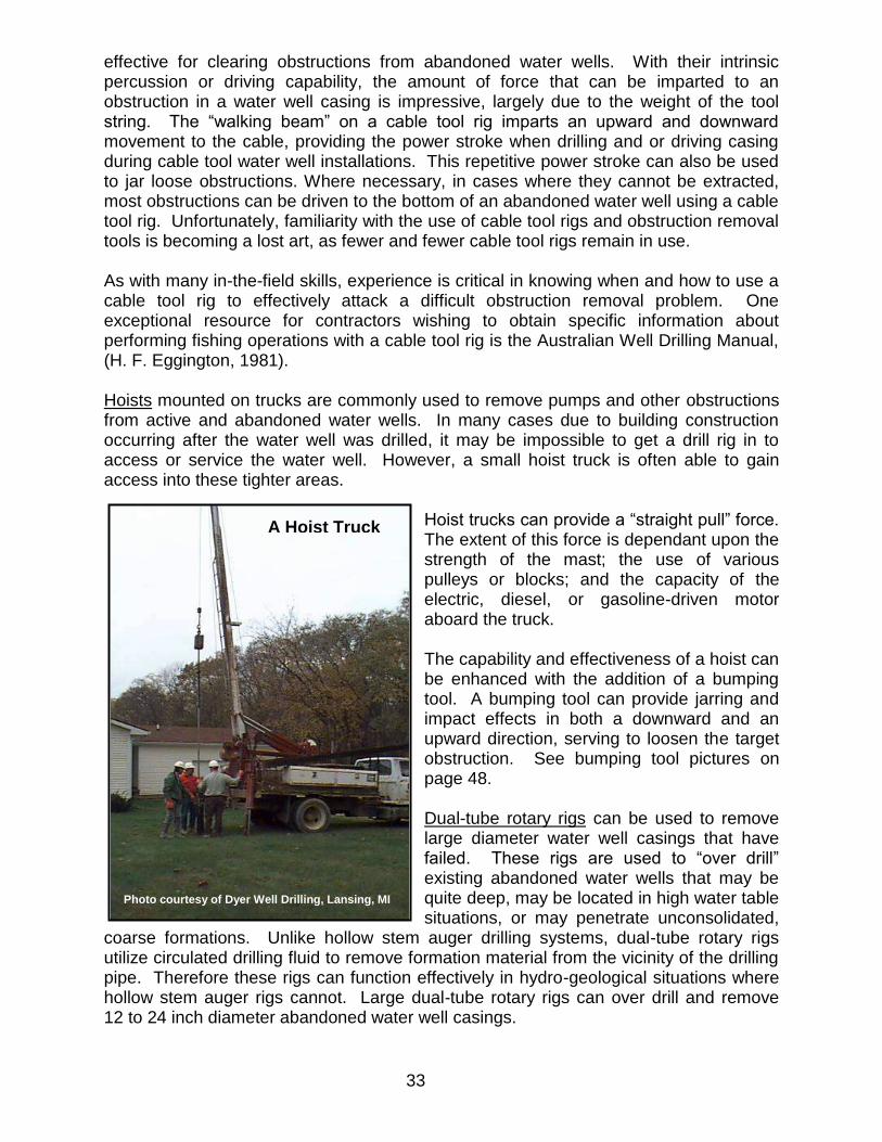
33
effective for clearing obstructions from abandoned water wells. With their intrinsic percussion or driving capability, the amount of force that can be imparted to an obstruction in a water well casing is impressive, largely due to the weight of the tool string. The “walking beam” on a cable tool rig imparts an upward and downward movement to the cable, providing the power stroke when drilling and or driving casing during cable tool water well installations. This repetitive power stroke can also be used to jar loose obstructions. Where necessary, in cases where they cannot be extracted, most obstructions can be driven to the bottom of an abandoned water well using a cable tool rig. Unfortunately, familiarity with the use of cable tool rigs and obstruction removal tools is becoming a lost art, as fewer and fewer cable tool rigs remain in use. As with many in-the-field skills, experience is critical in knowing when and how to use a cable tool rig to effectively attack a difficult obstruction removal problem. One exceptional resource for contractors wishing to obtain specific information about performing fishing operations with a cable tool rig is the Australian Well Drilling Manual, (H. F. Eggington, 1981). Hoists mounted on trucks are commonly used to remove pumps and other obstructions from active and abandoned water wells. In many cases due to building construction occurring after the water well was drilled, it may be impossible to get a drill rig in to access or service the water well. However, a small hoist truck is often able to gain access into these tighter areas.
Hoist trucks can provide a “straight pull” force. The extent of this force is dependant upon the strength of the mast; the use of various pulleys or blocks; and the capacity of the electric, diesel, or gasoline-driven motor aboard the truck. The capability and effectiveness of a hoist can be enhanced with the addition of a bumping tool. A bumping tool can provide jarring and impact effects in both a downward and an upward direction, serving to loosen the target obstruction. See bumping tool pictures on page 48. Dual-tube rotary rigs can be used to remove large diameter water well casings that have failed. These rigs are used to “over drill” existing abandoned water wells that may be quite deep, may be located in high water table situations, or may penetrate unconsolidated,
coarse formations. Unlike hollow stem auger drilling systems, dual-tube rotary rigs utilize circulated drilling fluid to remove formation material from the vicinity of the drilling pipe. Therefore these rigs can function effectively in hydro-geological situations where hollow stem auger rigs cannot. Large dual-tube rotary rigs can over drill and remove 12 to 24 inch diameter abandoned water well casings.
Photo courtesy of Dyer Well Drilling, Lansing, MI
A Hoist Truck

34
Backhoes or Excavators are often used for extracting pumps and drop pipes from abandoned water wells because they are readily available to contractors and they seem expedient to use. Unfortunately, they can be misused in situations where pumps or jet
assemblies (and associated drop pipes) are stuck in water wells. Often the water well casing, pump, or jet assembly parts have become fused together and may be stuck solidly in the water well casing. Trying to use a backhoe in this situation can result in breaking off the drop pipe down in the water well and exacerbating the obstruction removal effort. Generally, this method of removing obstructions from abandoned water wells should be avoided. In cases where the pump and drop pipe are not stuck in the water well, a chain or cable can be attached between the drop pipe or pitless adapter body and the backhoe’s hydraulic excavator arm. A lift of the hydraulic arm by the backhoe operator is typically used to loosen the drop pipe and pump. Once loosened, these parts can be manually pulled out by a helper.
Vacuum trucks have been used to uncover buried wellheads during well location and plugging activities. They are useful when dealing with abandoned water wells that have been buried in gravel, glacial drift material, or other debris. Vacuum trucks have also been used to evacuate material from large diameter abandoned “crock” or dug water wells. In West Branch, Michigan, as part of a Clean Michigan Initiative (CMI) Abandoned Well Grant project, a vacuum truck owned by the city and operated by the Department of Public Works (DPW) was used to remove soil from over a buried abandoned flowing water well and then to keep the area around the water well dewatered while the drilling contractor removed a difficult obstruction from the water
Hydraulic Excavator with Chain
DEQ Photo
Vacuum Truck
Photo courtesy of Tasco Vacuum Trucks, Inc., Martinsville, IN

35
well casing. The vacuum truck was used because the abandoned well was located in a part of the city where there was no place to dispose of the discharge water during the obstruction removal and plugging procedure. Their truck had the capability to lift rocks as large as 12 inches in circumference from depths approaching 20 feet. The West Branch DPW crew mentioned that the vacuum truck suction was so intense that, even run at idle, larger rocks often jam at the first restriction in the suction piping (the upper elbow) and that, in some cases, care must be taken to avoid overly restricting the thin-walled suction pipe lead due to the potential for the suction pressure to collapse the pipe. Jetting using compressors and air or water can remove soil, small stones, brick fragments, wood, and other debris that may be found in improperly abandoned water wells. Where demolition activities have taken place and water well casings have been sheared off below grade, all kinds of things can fall into the water well. Where old abandoned water wells fall into disrepair and the well caps are removed (leaving the water well open at the surface) they become attractive disposal sites for all sorts of objects. In areas that seasonally flood, abandoned water wells can act like a drain, transporting soil and surface water contaminants into deep water bearing aquifers. Each of these mechanisms can result in an abandoned water well that is full of extraneous materials that must be removed before effective abandoned water well sealing can be accomplished.
To remove soft or unconsolidated debris from abandoned water wells, jetting or surging with water or air can be employed. The common jetting arrangement involves using a 10 foot section of steel pipe connected to a coil of flexible 1 inch or 2 inch diameter polyethylene pipe that is connected to either an air compressor or to a water pump and bulk tank. The contractor uses the air or water in a surging action to “blow” the soil and/or debris out the top of the water well casing. Aggregate, wood, soil, or bentonite can be removed from fairly deep
down in an abandoned water well using this method. To help reduce clogging of the jetting pipe as it is pushed into the debris or soil, its terminal end should be cut at a 45 to 60 degree angle. Also, some contractors use small, hollow, pointed nozzles for jetting. It is not unusual for debris to settle above a hard obstruction in an abandoned water well. Removing the debris or soil from above the hard obstruction is necessary to make the extraction process go more smoothly by eliminating “sand-locking” and other similar
Photo courtesy of Tasco Vacuum Trucks, Inc., Martinsville, In
Vacuum Truck
Jetting Nozzle
DEQ Photo

36
jamming effects. In addition, removal of debris and soil allows the contractor to expose the top surface of a hard obstruction so that fishing tools can be attached. A compressor capable of developing a minimum pressure of 60 pounds per square inch (PSI) and moving 100 cubic feet per minute (CFM) of air is recommended for air jetting 2-inch water well casings. For larger water well casings (4 or 5 inch), 185-225 CFM is necessary to effectively lift the debris up and out the top of the casing. For water jetting, a pump pressure of between 60 and 100 PSI that will deliver 25-30 gallons per minute (GPM) is recommended. The intent is to induce a high friction loss so as to scour the inside of the water well casing. Pump or compressor pressure levels must be monitored to avoid exceeding the maximum pressure rating of the polyethylene pipe or associated fittings (R. Webb, 2010).

37
REMOVING DROP PIPES, PUMPING COMPONENTS, AND WELL CASINGS Maintaining Control of Drop Pipes and Submersible Pumps On most abandoned water well sites, when the contractor arrives at the site, the well seal and drop pipe or the well cap and the pitless adapter assembly are still present in their original configuration. If the well cap or seal is still in place, the contractor should carefully remove the cap or loosen the well seal in a manner that will not result in any attached components dropping down into the water well. The approach should be the same as if he were going to repair the existing pumping equipment. Contractors must refrain from just cutting off the casing and pitless adapter retaining pipe or the drop pipes. Such an action can result in the entire pumping component string falling down into the water well and becoming lodged, making it much more difficult to deal with.
Removal of the drop pipe and pump components from deeper water wells will normally involve use of a hoist truck or the casing line on a drill rig. After loosening the well seal or pitless adapter fitting, a pipe vise or retaining clamp should be attached to the drop pipe as soon as possible and used between sections of drop pipe as they are
sequentially removed. In situations where the pumping equipment is stuck in the water well, but the drop pipe is visible, a threaded connection should be made between the drop pipe and a bumping tool suspended from the hoist or drill rig cable. When drop pipe is in good condition, you have a better chance of removing all of it (along with the pump) without incident. Use a quality metal coupling of an appropriately threaded length to join the bumping tool to the drop
pipe. It may take a significant amount of time using the bumping tool to jar loose the pumping assembly. Most contractors indicate that persistence and patience pays off and that impatience results in additional problems (like broken off drop pipes). Drop Pipe Materials Drop pipes may be polyvinyl chloride (PVC), polyethylene (PE) pipe, galvanized steel, or black steel pipe. Each material has characteristics that make it either a problem or an asset at the time it must be removed. Steel pipe grade will often determine how well it holds up over time. Galvanized pipe is often in better condition and can reliably be expected to withstand substantial jarring with a bumping tool. Some grades of black steel pipe used for drop pipe may be rusted to the point where it is not structurally sound. It is not unusual for it to break off during removal attempts. Similarly, PVC drop pipe can accept a very limited amount of jarring or bumping but may remain intact long enough to allow the contractor to free up the pumping equipment. However, it is common for PVC drop pipe to break off during extraction efforts at the point of connection to the bumping tool due to the intrinsic weakness of the coupled or threaded portion of the pipe. It is also common for PVC pipe to break off down hole many times during the extraction
A Pipe Vise or Retaining Clamp
Photo courtesy of Central Well & Pump, Muskegon, MI

38
process. Often, PVC and black metal drop pipes must be broken off or otherwise removed in sections down to the level of the pump, before the pump itself can be effectively attached to an extraction tool. Where PE drop pipe is encountered, it is possible to try to put upward “pulling” or upward “bumping” pressure on it, but it cannot be “driven” downward with any effect. It is difficult to reconnect to both PE and PVC drop pipe that breaks off down hole. Overshots with a terminal configuration that redirects the drop pipe into the center of the tool are helpful in reestablishing connection. Tools with a “cut lip” or a “collar” configuration are often effective in this situation. Drawdown Seals Drawdown seals must be removed from abandoned water wells before the abandoned water wells are plugged. If they are not removed, plugging material cannot get past the seal resulting in the portion of the water well below the seal remaining unplugged.
Drawdown seals typically come out when the drop pipe is removed. The flexible nature of the outer seal makes drawdown seals relatively simple to extract. However, in cases where a submersible pump is stuck in the well below a draw down seal, it is not possible to attach a fishing tool to the pump without first eliminating the drop pipe and the draw down seal. This may require breaking off the section of drop pipe that includes the drawdown seal. Once this section is removed, a firm connection can be made to the pump and a bumping tool can be used to jar the pump free. Hydraulic jacks During water well abandonment activities being conducted at groundwater contamination sites, water well code enforcement sites, or sites where an annulus is present around an abandoned water well casing, it is possible to remove the water well casing using a hydraulic jack.
Often these casings have been in place for many years and may not be removable using straight pull methods. Employing hydraulic jacks to pull the water well casing is less expensive than milling the casing out with a rotary rig or over-drilling with a hollow stem auger or dual-tube rotary drill rig. Where a hydraulic jack is used, a solid, noncompressible base must be provided under it, on the ground near the water well casing, to prevent the jack from pushing itself down into the ground. Heavy wood timbers are often employed to achieve this solid base of support. In some cases, where large diameter steel casing is involved, steel tabs are welded onto the abandoned water well casing to provide an anchor point for using hydraulic jacks. Alternatively, holes may be cut in a water well casing with a torch and steel rods are placed into the holes to provide a structural point against which the jack may apply upward pressure.
A Drawdown Seal
DEQ Photo

39
Small hydraulic jacks can also be used for extracting drop pipes, packer jet assemblies, drawdown seals, and submersible pumps from abandoned water wells. They consist of
a pair of short 18 to 24 inch long, 1½ inch diameter hydraulic cylinders mounted parallel to one another, connected at the top and the bottom. The jack is actuated using a small electric pump. In order to use a hydraulic jack to pull the drop pipe out of an abandoned water well, the contractor threads a section of pipe onto the top end of the drop pipe, thereby extending it up above the water well casing. The hydraulic jack is placed over the top of the drop pipe. A set of slips attached to the jack are set tightly around the drop pipe (tapped into place with a hammer). Some small hydraulic jacks are compact enough to fit into crawl spaces, beneath decks, and into basement areas with limited vertical clearance. They enable contractors to remove obstructions from otherwise inaccessible abandoned water wells. Using
a small hydraulic jack, the drop pipe can be lifted in short increments and cut off in pieces if the water well is located in an area with limited overhead clearance. Care must be exercised when using hydraulic jacks for removing obstructions from some 2 inch water well installations where the water well casing is not effectively grouted or is relatively loose in the bore hole. If the obstruction is lodged tightly in the water well, the well casing itself may inadvertently be lifted. This can result in partial borehole collapse below the well casing as it is pulled, making it impossible to properly plug the lower portion of the borehole. In this situation, attempting to drive the obstruction to the bottom of the water well may be the preferred method of abandonment. On groundwater contamination sites, over drilling the entire water well casing using a method described in ASTM Standard D 5299-92 may be the best way to proceed. Mobile Pipe Pulling Devices Long drop pipes with pitless adapter connections, drawdown seals, jet assemblies, and submersible pumps can be removed from water wells that are located in areas inaccessible to vehicle-mounted hoists or drill rigs using small mechanical devices.
A small Hydraulic Jack
Photo courtesy of Central Wells & Pump, Muskegon, MI
A “Pump Out”
Photo courtesy of Central Wells & Pump, Muskegon, MI

40
Commonly called “pump outs,” they consist of a pair of rotating, opposing rubber tracks driven by electrical motors, mounted on a small wheeled cart. The drop pipe is sandwiched between the tracks and as the tracks rotate, the drop pipe is lifted and extracted by friction grip. These devices allow one operator to remove the entire drop pipe and pumping equipment assembly without assistance. These devices are much less effective when the pump, drawdown seal, packer, or jet assembly is solidly lodged in the water well casing. Submersible Pumps Steel water well casings that have been in service for many years eventually can become corroded and their inner surface encrusted with mineral deposits. Submersible
pumps also can become encrusted with scale and iron deposits over the years resulting in the pump becoming fused to the water well casing. Additionally, the inner surface of the water well casing often becomes encrusted with scale and mineral deposits above the pump, especially in the area of the air-water interface. The clearance between the pump and the inside surface of a 4 inch steel water well casing is minimal when they are new, so it is not difficult to understand why scale and corrosion can increase the difficulty in removing an old pump. On problem water wells, it is helpful to remove the scale deposits on the inside surface of the water well casing above the pump first, before trying to extract the pump itself. If not, the pump will continually
become stuck as the contractor attempts to pull it. This can be accomplished in a number of ways. For limited amounts of scale, the simplest way is to run a coarse bristle brush or a surge block device down the water well on a tool string and physically scrape the sides of the casing. The debris resulting from this swabbing action must be surged out of the well with water or air before trying to pull the pump. On more intensively encrusted casings, effective cleaning can require the use of a rotary drill rig and various drill bits (like the recycled drag bit previously mentioned in this manual).
Submersible Pump in a 4 inch Steel Well Casing
Photo courtesy of Rich Well Drilling, Sandusky, MI

41
In an attempt to dissolve encrustations, it is not uncommon for contractors to utilize chemical treatments (like muriatic acid) to try to break down the encrustation build up, before attempting to pull the submersible pump. Care must be exercised to utilize only approved chemicals for this purpose. Attaching the extraction tool to a submersible pump that is locked in the water well
casing due to encrustation from minerals in the water can be accomplished after the drop pipe has been eliminated and the top of the pump is exposed. If a threaded connection is possible, it will be the firmest grip possible and should be attempted. Many extraction tool options are available, each with its own set of advantages and disadvantages. Some useful combinations are:
Exposed Surface of Pump Tool Options Barb Fitting Die Collar, Box Tap, Recycled Drag Bit Threaded Pump Connection Standard Thread or Taper Tap Drop Pipe Section Overshot or Box Tap Damaged Pump Surface Taper Tap or Rotary Wash over Shoe with Carbide Pump in any configuration Drive Stainless Steel Overshot Once the connection is made between the fishing tool string and the pump, the pump can normally be jarred loose using a bumping tool or fishing jars. This jarring/bumping process can take time but is normally successful with patience and perseverance. Two-Wire Submersible Pumps It is not uncommon for old submersible pumps that are solidly lodged or fused in a steel water well casing to be pulled apart during intensive pounding and jarring during the extraction attempt. Sometimes they come out in pieces. When this happens, the oil reservoir associated with the pump’s start capacitor can be damaged, releasing the oil into the water well and surrounding aquifer. Some older 2-wire submersible pumps were equipped with a capacitor that contained PCB oil.
Photo courtesy of Dyer Well Drilling, Lansing, MI
Submersible Pump and Drop Pipes
DEQ Photo

42
When a contractor encounters a 2-wire submersible pump that is firmly stuck in the water well and no information is available concerning the make and model number of the
pump, the DEQ advises that no actions be taken that could damage the pump and release the PCBs. The contractor should contact the LHD and advise them of the situation, the pump should be entombed in place with neat cement, and appropriate notes put on the Abandoned Well Plugging Record describing why the pump was not removed. See the DEQ document “Advisory on PCBs in Older Submersible Water Well Pumps,” August 24, 2005. This document also
contains the recommended procedures and precautions to take when cleaning a water well contaminated with PCB oil. Recommended procedures for PCB cleanups are also located on the DEQ website: www.michigan.gov/waterwellconstruction. Deep Well Packer-Jet Assemblies Removing deep well packer-jet assemblies from abandoned water wells poses similar problems to those encountered when dealing with submersible pumps. There is a center water-conveying line (like the drop pipe on a submersible installation) that is the key to removing the jet assembly. Depending upon the material type and condition of the suction line, it can be used to pull the jet. Where the jet is stuck in the water well casing, extraction methods involve attaching a fishing tool string, which includes a bumping tool, to the suction line and jarring the jet loose. A threaded connection is used whenever possible. In cases where the suction line breaks off or is not a metal pipe, the suction line may have to be removed all the way down to the jet before firm attachment with an obstruction removal tool can be made to the jet assembly. Where the contractor is not successful in establishing a standard threaded connection into the jet using a die collar or a small tapering overshot, a taper tap may be used to thread into the jet assembly body. Once firmly attached to the fishing tool string, jets can normally be jarred loose and extracted from the water well.
DEQ Photo
Brass packer-jet assemblies
Two-Wire Submersible Pumps
DEQ Photo

43
Packer jets are most typically encountered in 2-inch diameter water wells with steel water well casings. It is not uncommon for the casings and jets to be corrosion-fused together. Depending upon what material the jets are made out of, some are more difficult to remove than others. Jets made out of brass are less difficult to remove. Tools can be threaded into them and their surfaces are malleable. Jets made out of cast iron are much more challenging due to their tendency to fuse more tightly to the steel water well casing and no “give” to their surfaces. Contractors report that while jarring or pounding on them during extraction efforts, it is not unusual for cast iron jets to be driven through the side of the water well casing, especially if the casing itself has deteriorated. Where a jet is driven through the side of the water well casing, the contractor should remove the fishing tool string and immediately plug the water well. A tremie pipe should be placed as far into the water well as possible and grout pumped from that point upward to the surface. The contractor must describe the unsuccessful removal attempt and the resulting plugging procedure on the Abandoned Well Plugging Record in the comments section. See page 84 for more details on record filing. Installations with Pump Rods Pump rods are commonly observed in older water wells at windmill and hand pump sites. The rods come in various lengths, are typically either wood or metal, and extend down into the water well casing. Most pump rods are joined together with couplings that are larger in diameter than the rods. There are some flush joint rods, but they are far less common. There are two basic types of pumping systems that employ pump rods, those with a cylinder down in the water well and that have an associated drop pipe that conveys the water to the surface, and those that use the casing itself as the cylinder and the water conveying pipe. In the first case there is a drop pipe that runs from the surface down to the cylinder. The plunger and check valve are an integral part of the cylinder and the rods extend up to the surface inside the drop pipe. In the second case, there is a Bremer check valve at the bottom of the water well casing and a Bremer plunger with a set of leathers on the bottom end of the last pump rod. Where a cylinder is being used, the drop pipe will be around the pump rod and if the rod is broken off or damaged, it may not be visible. Where a cylinder is not used, the uppermost pump rod may be visible just below the top of the water well casing or it may be located at some unknown depth down in the water well.
Photo courtesy of Mauer & Parks Well Drilling, Lansing, MI
Pump rod being extracted

44
Depending upon the system involved, different extraction methods will be necessary. For the installations that include a drop pipe and a cylinder, methods used for removal of submersible pumps on rigid drop pipes can be employed. For the more common installations that do not have a separate drop pipe and just have the pump rod attached to a plunger, the following methods can be used to extract them. Where the upper rod is visible and accessible, a threaded connection should be made to the fishing tool string that includes a bumping tool. Normally, it takes just a few bumps to free up the pump rod and plunger assembly and it can be easily removed. However, if the rod and plunger assembly has fallen down into the water well, the pump rod extraction tool described on page 40 may be used. This tool is threaded onto the downward-facing end of a bumping tool. It works by bumping it down over the pump rod, past the first few metal couplings. The tool can be bumped past the couplings because the gripping edges are aligned in the proper direction, however when the tool is pulled upward, these gripping edges catch on the couplings. Once the gripping edge is pushed past the lower edge of the coupling, a series of upward bumps usually frees up the plunger and rod assembly allowing the contractor to bring the rod up to the surface where it can be disassembled section by section. Two-Pipe Deep Well Jet Assemblies Two-pipe deep well jet assemblies were commonly used in 4-inch steel water well casings. One pipe is a suction line and conveys the water upward, the other is a return or drive water line in where the water flow is downward. Both are suspended inside the water well casing from the point of connection to the pitless adapter or from the sanitary well seal. Normally, two-pipe deep well jet assemblies do not pose an extraction problem. With these installations, there is no seal between the inside surface of the casing and the jet assembly like with a packer jet, so it is less common for them to be encrusted on to the water well casing. Components are usually removed using a pump hoist or by hand. In cases where metal drop pipes are used, the contractor simply attaches the larger diameter drop pipe to the tool string using a threaded connection and proceeds to lift the assembly. Where nonmetallic drop pipes are used and the water well casing is heavily encrusted or debris has fallen into the water well above the jet, it may be more difficult to pull the jet assembly and the contractor may have to use a bumping tool or to work his way down, breaking off sections of each pipe as he proceeds. Once a firm connection can be made to the jet assembly, it normally can be extracted without great effort. The difficult part is removing deteriorated or nonmetallic pipes above the jet so the contractor can get a firm hold on something solid enough to bump or drive. Shallow Well Jet Pump Installations (with Foot Valves) In most cases, the drop pipe from a surface mounted shallow well jet pump is simply suspended from the well seal and is not attached to anything inside the water well casing. The drop pipe and foot valve are typically a significantly smaller diameter than the water well casing, so they do not normally become encrusted in place. The exception is on small, 1¼ inch diameter driven water wells with 1-inch drop pipes. Some of these installations may become heavily encrusted with mineral deposits; and, therefore, present obstruction removal issues. These installations are typically on very shallow water wells in areas where the static water level is relatively near the ground surface.

45
ROTARY RIG FISHING TOOL STRING COMPONENTS Engaging a fishing tool onto an obstruction like a submersible pump, a drop pipe with a packer or a drawdown seal, a deep well jet assembly, or a check valve is often only part of the task of attempting to remove the obstruction from the abandoned well. Pumping system components in older wells often bond to the well casing over time due to corrosion of metal parts and encrustation associated with water chemistry. Most of the time, it is necessary to impart a jarring, pulling, or driving force to the obstruction to get it to move. Bumping tools are designed to accomplish this task. Bumping tools are either attached to a rotary drill string (when using a bumper sub), to a casing line on a rotary drill rig, to the cable or the casing line on a cable tool rig, or are suspended on a cable from a hoist truck. It is recognized that many of the fishing tool string components discussed in the following sections can be very costly to own. It is not uncommon for water well drilling companies to rent the more complex fishing tool string components from oil field service and supply companies. Depending upon the complexity of the fishing operation, the size of the abandoned well casing, the type of obstructions present, and the public health or environmental considerations involved, use of the following fishing tool options may be considered. Safety Joints A safety joint is used above fishing tools on rotary fishing tool strings to allow the contractor to disengage from the fishing tool in the event that it becomes lodged in the
well. They can prevent the loss of an entire fishing tool string if the obstruction will not move and the tool will not disengage from the obstruction. Where bumper subs or fishing jars are also used as part of the fishing tool string, they should be located above the safety joint. Bumper Sub Design and Use On the terminal end of a rotary drill rig fishing tool string, a component called a “bumper sub” can be used to deliver both upward and downward impacts on downhole obstructions. A rudimentary bumper sub consists of two working parts, a hardened metal sliding spline, the lower end of which is configured to form a shouldered hammer, and a hardened metal hollow body which is configured to just fit the spline diameter. The spline travels a set distance before striking the lower end of the metal body (on the down stroke) or the upper end of the body (on the up stroke). Bumper subs are “flush-joint” tools that are made in various sizes to match the inside diameter (ID) of a given size well casing. The lower end of the bumper sub has a threaded joint for attachment of drill pipe or a fishing tool. The weight of the rotary drill rods or fishing tool string that is run
above the bumper sub is employed to provide the force necessary to deliver a blow that is transmitted through the sub to the obstruction. The tool string is raised, then dropped to deliver the downward blow, hopefully dislodging the obstruction from the well casing. To deliver an upward blow, the rotary drill string is first lowered, then quickly raised to
Picture courtesy of Gotco International, Tomball, TX

46
deliver an upward blow against the top of the tool body, which imparts an upward pulling action on the extraction tool and the attached obstruction. Alternating between upward and downward blows is intended to loosen the obstruction, allowing it to be either extracted from the well or driven to the bottom of the well if extraction is not possible. Some bumper subs have a hex-shaped spline that allows the contractor to rotate the
lower portion of the sub and the attached fishing tool. More complex rotary bumper subs utilize an internal piston mechanism to increase the bumping effect and are operated in a manner that utilizes sudden release of tool string tension (downward) or recoiling action (upward) to impart intensive impacts on the obstruction (Gotco International, 2010). Table drive rotary rigs can provide effective driving and pulling action using a bumper sub due to the configuration of their hydraulics and
the operator’s ability to quickly lift and lower the fishing string with sudden, substantial force. Bumper subs are commonly used on table drive rotary rigs in oil field applications, but are less common in the water well drilling industry. Basic bumper subs are not as useful on top head drive rotary rigs. Typically, top head drive rotary rigs have only limited capability to impart much bumping force because the fishing tool string is not normally “slammed” downward. Upward pounding force is also very limited because not only the fishing tool string, but also the entire drilling assembly must be raised by the hydraulic system during an upward-directed blow, greatly limiting the upward impact force. The more complex, piston-type bumper subs would be more useful to top head drive rotary operators. Bumper subs are effective tools, but they are very expensive. Water well drilling contractors may prefer to rent bumper subs from supply companies.
Picture courtesy of Gotco International, Tomball, TX
Rotary bumper sub
Photo courtesy of Mid-State Oil Tools, Mt. Pleasant, MI

47
Rotary Fishing Jars When conducting fishing operations using a rotary drill rig, rotary fishing jars are used to jar loose obstructions and to help prevent the fishing tool string from becoming accidentally stuck down in the well. Rotary fishing jars are fairly complex tools that operate using an internal hydraulic piston.
Once an obstruction has been solidly engaged to the fishing tool, the rig operator applies upward hydraulic force to the fishing tool string, causing it to stretch. As the jar begins to open, the piston measures the hydraulic fluid in the jar. Once the jar has opened to about half its stroke length, the internal piston will release and the jar will suddenly open to its full stroke length, releasing the force of the stretched tool string, resulting in delivery of an upward blow. The jar is reset by lowering the tool
string, which recloses and resets the hydraulic piston in the jar (Gotco International, 2010). Rotary drilling jars can be rented from oil field service companies.
Picture courtesy of Gotco International, Tomball, TX

48
HOIST TRUCK-MOUNTED BUMPING TOOLS A bumping tool or slide hammer is the most commonly observed device used by water well drilling contractors to loosen obstructions in abandoned water wells. They are internally similar in design to bumper subs, having a spline or shaft with a shouldered hammer at the terminal end that travels a specified distance inside a hollow metal body. A bumping tool can deliver an impact to an obstruction either bumping upward or
downward. A bumping tool differs from a bumper sub in that a bumping tool is larger in diameter than the well casing, they are used above ground level and they are attached to a cable, not threaded onto a rotary fishing tool string. When using a bumping tool, a small diameter (usually 1½ inch) 10 foot section of pipe is threaded into the bottom of the bumping tool, then additional sections of pipe are
joined (threaded and coupled) down to the approximate level of the obstruction. The fishing tool itself is attached to the bottom of the last pipe section. Bumping tools may be suspended from a cable on a truck-mounted hoist, from a cable tool rig, or from a drill rig’s casing hoist line. The rig operator alternates short, upward lifting, and then downward (free fall) driving actions on the bumping tool to deliver the jarring force to the obstruction. Depending upon the type of fishing tool being used and the integrity of the attachment point to the obstruction, it is common for rig operators to have to reattach the fishing tool to the obstruction a number of times during the extraction process. Bumping tools of different weights are used based upon the obstruction removal task to be completed (B. Brewer, 2010).
Photo courtesy of Central Wells & Pump, Muskegon, MI
Bumping Tool
Photo courtesy of Dyer Well Drilling, Lansing, MI
Bumping Tool

49
CABLE TOOL RIG FISHING TOOL STRINGS Due to their ability to deliver intensive percussion forces down hole, cable tool rigs are ideally suited for clearing obstructions from abandoned water wells. A cable tool rig fishing string can deliver an intensive blow or an intensive pulling force to an obstruction. The rig’s cable is routed from a rotating cable drum, horizontally to a sheave at the moving end of a “walking beam.” The walking beam is anchored near the cable drum and pivots up and down from that point. The cable passes over a sheave at the end of
the walking beam on its way up to the top of the mast, where it passes over a crown sheave, and downward to the suspended fishing tool string. Raising and lowering the walking beam arm results in raising and lowering the tool string. As the walking beam lowers, it takes up a length of cable. After the walking beam completes its downward travel, it then elevates suddenly. The cable is allowed to basically free-fall in a short downward stroke that utilizes the weight of the tools to deliver a substantial downward blow to the obstruction. The downward travel of the walking
beam applies a strong pulling action on the cable. This action provides alternating pounding and pulling Effects on the obstruction (L. Rich, 2010). A typical cable tool “fishing” string used for removing obstructions from an abandoned well consists of the drilling rig cable, a rope socket, a set of long-stroke fishing jars, a short sub or section of drill pipe, and a drill bit or a specialized obstruction removal tool. Many fishing tools have been developed over the years to extract damaged or disconnected cable tool drilling string components from wells installed with this method. Some of the same tools can be used to remove obstructions from abandoned water wells. Other fishing tools are highly specialized and are designed to accomplish specific, limited tasks.
Short Stroke Drilling Jars
Photo courtesy of Rich Well Drilling, Sandusky, MI

50
Long Stroke Fishing Jars A long stroke fishing jar (LSFJ) assembly is a fishing tool string component used on a cable tool drill rig. Long stroke fishing jars typically have an 18 to 30-inch stroke or travel distance and look like a pair of two tined forks that are aligned at 90 degrees to one another and slide together in opposing directions. It is considered normal practice to include a set of LSFJs on any fishing tool string to allow the drilling contractor to “jar” loose the fishing tool from the obstruction and prevent loss of the entire tool string if the fishing tool becomes stuck down hole. The contractor can impart either an upward or a downward blow to an obstruction when using a set of LSFJs.
Photo courtesy of Rich Well Drilling, Sandusky, MI
Long Stroke Fishing Jars on a Cable Tool Fishing String

51
FISHING TOOLS Fishing tools are devices that are intended to capture, attach to, and ultimately facilitate the removal of obstructions from water wells. Contractors use these tools in many ingenious ways and in some cases, develop new fishing tools to suit specific obstruction challenges. Fishing tool complexity ranges from those that are exceedingly simple to some that are technically and operationally advanced. There are specialty companies in the oil and gas exploration service industry that design, build, rent, and operate the most complex fishing tools. Some of these specialty companies can provide obstruction removal consultation services, specialty tool use assistance, and other field services to water well drilling contractors. The following fishing tools range from basic to complex. Each has its own advantages, disadvantages, and intended application. Contractors who conduct obstruction removal activities should become familiar with these tools, their appropriate applications, and their limitations. Magnets Magnets are useful for clearing steel objects from wells that are not tightly lodged in the
well casing or bore hole. Water well drillers using various types of obstruction grinding or cutting tools may employ magnets to remove the resulting metal fragments or pieces. Magnets are also useful for cases where metal tools or other metal objects have been accidentally dropped into a water well. Magnets used for obstruction removal purposes are rated for specific maximum lifting capacities expressed in “pounds pull.” This capacity is based upon the diameter and size of the magnet. Taper Tap A taper tap is the most
commonly used obstruction extraction tool used by water well plugging contractors. Every water well drilling contractor who works on clearing and plugging abandoned water wells should have a taper tap on hand. Taper taps are normally about 10 to16 inches long and 1.5 to 2.5 inches in diameter, taper to a point at their terminal end, and have helical threads or similar friction teeth arranged along the tapered portion of the tool.
Photo courtesy of Mid State Oil Tools, Mt. Pleasant, MI
Fishing Magnets

52
Taper taps may be attached to the terminal end of a rotary or cable tool fishing string by being threaded on to a sub or section of drill rod below a set of jars, or they can be attached to a section of steel pipe on a truck mounted hoist that is equipped with a bumping tool. They can be used to remove drop pipes, submersible pumps, check valves, and other hard obstructions that are stuck in abandoned water wells. Because most taper taps have helically-arranged friction threads or teeth, they are usually screwed or
“tapped” into the target obstruction by the water well contractor. This is accomplished using pipe wrenches rather than through use of the rotary capabilities of a drill rig. A challenge often encountered when using taper taps is getting the end of the tap aligned properly with the obstruction. A modification can be made to allow it to be more easily aligned down in the water well with the obstruction by “skirting” it with a metal or PVC sleeve that extends a few inches beyond the tip of the taper tap. By having the downward-facing leading edge of the “skirt” configured with “cut lips” the obstruction, which may be leaning against one side of the well casing, can be manually repositioned in relation to the taper tap so the tap can be threaded more easily into the obstruction.
Die Collar A die collar has the upper pipe-like end threaded to allow attachment to the fishing tool string or sub, and the lower end sequentially enlarged into a conical configuration that is sized to surround the obstruction. The tool is hollow at the enlarged conical end with helical teeth or threads on the inside surface. A die collar is used by rotating the tool over or onto the obstruction. As the die collar is rotated, the helically-arranged inner surface threads or teeth bite into the surface of the obstruction. The threaded opening gets incrementally smaller the further the obstruction is threaded inside, resulting in a friction grip. Die collars are used to remove obstructions in abandoned water wells where clearance is present on the sides of the obstruction but the exact diameter of the upper end of the obstruction may not be known.
DEQ Photo
Taper tap
A Die Collar
Picture courtesy of Logan
Oil Tools, Houston, TX
Photo courtesy of Mid-State Oil Tools, Mt. Pleasant, MI
Taper tap
DEQ Photo
Taper tap

53
Box Taps Box taps are internally similar in design to die collars and are used in a similar manner. They are attached to a sub on a rotary rig or to the terminal end of a string of pipe sections attached to a bumping tool. They look like a short section of pipe that has the
inside surface finished with an aggressively tapering thread. The steepness of the taper is greater than that of a die collar, that allows them to catch obstructions of a wider size range. The thread is tapered so that when the drill string or lead pipe is rotated to the right, the tap gets tighter around the obstruction. Once attached to an obstruction down in the water well, the intent is to have the tool remain attached until both the obstruction and tool are brought to the surface where the obstruction is removed from the tool manually by the rig crew. Box taps are not mechanically “releasable.” Depending upon the type and position of the obstruction that is present, the outside diameter of a box tap may be sized to just fit the inside diameter of the well casing, thereby allowing it to catch larger diameter obstructions, or it may be downsized to
allow the rig operator to manually align it with an obstruction positioned off center inside the well casing. This box tap has a “cut lips” guide configuration that allows it to more easily capture and direct an obstruction into the center of the tool. Overshots Overshots are similar to box taps and die collars in that they are intended to go over the outside of an obstruction. An overshot may or may not be threaded or may have a series of slots or grooves on the inside surface to facilitate solid, more durable capture of the target. They are typically driven over top of the obstruction (encircling it) using a heavy tool string or a bumping tool. Once an overshot is solidly attached to an obstruction, it may lodge the entire tool string in the water well.
Box Tap
Photo courtesy of Mid-State Oil Tools, Mt. Pleasant, MI
Photo courtesy of Mid-State Oil Tools, Mt. Pleasant, MI

54
Therefore, it is important to utilize additional tool string components that have appropriate jarring, bumping, or disengagement capability to allow disengagement if it becomes necessary, to avoid loosing the entire tool string in the water well. Standard overshots are generally attached to a sub with a safety thread when used on rotary fishing tool strings. One unique type of overshot is designed to be sequentially “used up” as it is employed for removing stuck submersible pumps. This type of overshot is made from a 10 foot length of stainless steel pipe with the downward facing end beveled inward. It is driven over the stuck pump. The stainless steel pipe is strong enough to not be distorted during the driving activity and therefore does not become locked against the inside wall of the well casing. Once the pump has been captured, the overshot and pump are extracted from the water well and the section of stainless steel pipe containing the pump is cut off with a torch, then the downward facing end is re-beveled for the next use. A tool of this type can be used to remove a dozen or more submersible pumps, depending upon how much of the tool length is used up during each pump extraction job. Releasing/Circulating Overshots At times during the obstruction removal process it may become necessary to temporarily release an obstruction from an extraction tool. This capability can prevent the loss of an expensive tool or the loss of an entire tool string in the water well. This may be the case when the rig’s rotational torque or its upward pulling capability is inadequate to dislodge the obstruction. To address this problem, releasing/circulating overshots are available. These overshots consist of two main parts, an outer conveying tube attached to the fishing tool string and an inner grapple assembly that does the “gripping” work.
Releasing/circulating overshots are very complex tools. They come in a variety of configurations to serve many different applications downhole. The main advantage of a releasing overshot is the ability of the operator to initially attach it to an obstruction, then release it again if the obstruction is solidly stuck in the water well. Circulating overshots are valuable when formation materials or debris have accumulated above or around an obstruction and must be washed out before the obstruction can be properly engaged. Water is circulated through the drill string and out through openings in the overshot, similar to how drilling fluid flows through a rotary drill bit. A basic releasing overshot looks like a short pipe section configured with a tapered thread at the top and hollow at the bottom. The lower, hollow end’s inner surface is milled or surfaced with wide, spiral flanges. Matching helical
grapples are threaded onto the flanges and are held inside the tool with a retaining collar, the terminal end of which is either beveled to guide the obstruction into the
2 inch releasing overshot
Photo courtesy of Mid-State Oil Tools, Mt. Pleasant, MI

55
overshot or has a cut-lip configuration. Individual grapples are designed and sized to be used to remove obstructions that fall within a certain range of diameters. The shape and diameter of the obstruction must be compatible with the grapple size that is selected. Releasing overshots attach by being lowered over the top of an obstruction. The grapple in the overshot grips the obstruction when upward pressure is applied to the tool string causing the grapple threads and the inner spiral flanges to interact. A grip on the obstruction can be accomplished along the full length of the grapple. To release the obstruction, downward pressure is applied and the tool string is rotated. Releasing/circulating overshots are expensive and the grapples individually have a limited effective size range capability. It would be impractical for a water well drilling company to stock all the possible grapples needed to deal with the many potential sizes and shapes of
obstructions they typically encounter. When used, these tools are typically rented from oil and gas service and tool supply companies. In some cases, personnel from the service company will provide on-the-rig technical assistance when a water well drilling contractor rents their specialized tools.
Pump Rod Extraction Tool A simple tool using a 10-foot long piece of galvanized pipe may be made by the well plugging contractor to remove pump rods from abandoned wells. The piece of galvanized pipe is threaded at the top end, and a coupler is installed to allow the tool to be attached to a hoist cable or bumping tool. At 6- to 12-inch intervals along the pipe, saw cuts are made about 1/3 of the way through the pipe, alternating 90 to 180 degrees on each side of the pipe. The pipe is then hammered to “indent” the pipe below each saw cut. The indentation should be about ½ inch deep at the saw cut and taper downward, evenly to about 1 to 2 inches below the saw cut. This configuration results in a tool that can
Pump Rod Extraction Tool
Photo courtesy of Mauer & Parks Well Drilling, Lansing, MI
Photo courtesy of Mid-State Oil Tools, Mt. Pleasant, MI
Releasing overshot and grapple

56
be pushed or driven over pump rods such that the rod goes into the center of the tool where it is firmly gripped by the indentions or “barbs” made in the pipe. If the pump rod’s upper-facing end is down in the well, a funnel-shaped fitting may be added to the bottom of the tool for easier capture. The end of the galvanized pipe may then be flared outward or the end of the pipe maybe cut at a 45- to 60-degree angle. This will help the tool first center and then capture the pump rod if the contractor cannot see the pump rod and it is leaning against one side of the well casing. Once the tool has gripped the pump rod, the hoist is used to free the rod and plunger assembly using a straight pull or with the aid of a bumping tool. Once freed-up, the assembly can usually be lifted by hand, uncoupling each section of rod as necessary. Modified/Recycled Drill Bits Drilling contractors who are innovative often recycle used drill bits or drill string components to create special obstruction removal tools. Skill and experience with metal working and with the use of machine tools, along with knowledge about the specific configuration of the specific obstruction they are after, are all necessary to be able to fabricate an effective tool. Having an extensive, working knowledge of the potential problems that can be encountered during extraction jobs is also extremely valuable when designing an extraction tool. The following picture shows an example of a recycled, refabricated combination tool that both hones the inside surface of the well casing and also attaches to the obstruction. It is an old, used 3 7/8 inch drag bit that has been modified. This tool is used for reaming out 4-inch steel well casing and pulling out stuck submersible pumps. The outside diameter of the bit is machined to just fit inside standard 4-inch steel well casing. The inside, upper surfaces of the drag bit are machined to catch standard size drop pipe or barb fittings typically used with submersible pumps. This is a rotary rig tool used with water or drilling fluid to first “mill” the inside surface of the well casing, removing encrustation that may cause the pump to lodge as it is being pulled. After the bit has been used to clean up the inside of the casing, the milled debris are surged out of the water well, then the end of the bit is carefully rotated around the drop pipe, barb fitting, collar, or coupling on the pump. Limited bumping to initially break the pump loose may be necessary, but once loosened, it will normally come up without further trouble (L. Rich, 2010).
Photo courtesy of Rich Well Drilling, Sandusky, MI
Recycled Drag Bit
Photo courtesy of Rich Well Drilling, Sandusky, MI

57
Latch Jacks and Valve Grabs Many 2-inch wells in Michigan have a Bremer check valve installed above the telescoped well screen. These check valves have a brass bail on their upward end that is cast as part of the valve body. The bail is intended to facilitate easy extraction of the valve from the well when necessary. Because they are normally installed just above the
well screen in water wells terminated in unconsolidated formations, check valves do not normally have to be removed at the time a screened well is being abandoned. Only the screened interval below the check valve will remain unplugged in this situation and this does not pose a significant threat to the aquifer. However, if a water well is terminated in bedrock, with the well casing seated just into the rock, a check valve located at the end of the well
casing will prevent proper plugging of the open bedrock portion of the water well below the check valve because grout cannot be pumped past the check valve. To properly seal an abandoned “rock well” that has a Bremer check valve in the well casing, the check valve must be removed. There are tools specifically designed for this job, a latch jack and a spring steel grab. These tools are both used in a similar manner. Each type is lowered to a point just above the check valve then dropped onto the valve. A spring steel grab has two long, spring steel arms tipped with pointed “teeth” facing inward. Once the grab arms are pushed (sprung) past the check valve’s brass bail, the arms spring back into their original position and the teeth prevent the tool from disengaging from the check valve. The tool and the valve can then be pulled out of the well. See picture on previous page. A latch jack works in a similar manner but employs a swinging latch on one of its two arms to retain the check valve’s bail. Due to encrustations on the well casing and on the check valve itself, a contractor may have to use a bumping tool to assist with loosening stuck check valves. It is not uncommon to have valves break into pieces during extraction efforts.
Spring Steel Grab & Bremer Check Valve
DEQ Photo

58
Junk mill A junk mill is a bit that can be used on a rotary well drilling rig to mill or drill out hard metal obstructions in abandoned water wells that are not otherwise removable using
conventional fishing tools. Their use is normally reserved for situations where an obstruction is solidly lodged partway down in a water well and other extraction options have failed. Some are designed to mill away the casing itself, others are designed to just fit the inside diameter of the well casing and mill away anything inside the casing, such as drop pipe, pumps, or pump components. Junk mills are made out of thick-walled steel pipe with carbide-dressed surfaces either on the outside, the inside, on the end, or a combination of these. Some are configured with carbide-dressed blade-like abrasive surfaces. Some are configured with a “guide” or a carbide–dressed point. Junk mills can be used like other rotary drill bits, utilizing drilling fluid or water to flush cuttings away from the bit. When rotated, they grind away or “mill” the well casing, the obstruction, or both. Depending upon the intention of
the contractor, this milling action can grind up the obstruction eliminating it altogether, loosen it enough to extract it, or allow it to be driven to the bottom of the well. Entire well casings can be drilled out using junk mills. Normally, if this is the contractor’s intention, the tool is fabricated with a pilot point or guide sized to match the inside diameter of the well casing and carbide buttons or abrasives configured to mill the upward-facing end of the casing. The abrasive surfaces on junk mills wear out as the tool is used but can be refurbished with new carbide buttons or carbide pieces to allow for multiple uses. Junk mills are fabricated in various sizes and configurations, often for specific jobs or for specific applications. They are available for purchase or may be rented from oil field service and supply companies.
Photo courtesy of Mid State Oil Tools
A Selection of Typical Junk Mills
Junk Mill with a Pilot Point
Photo courtesy of Mid State Oil Tools
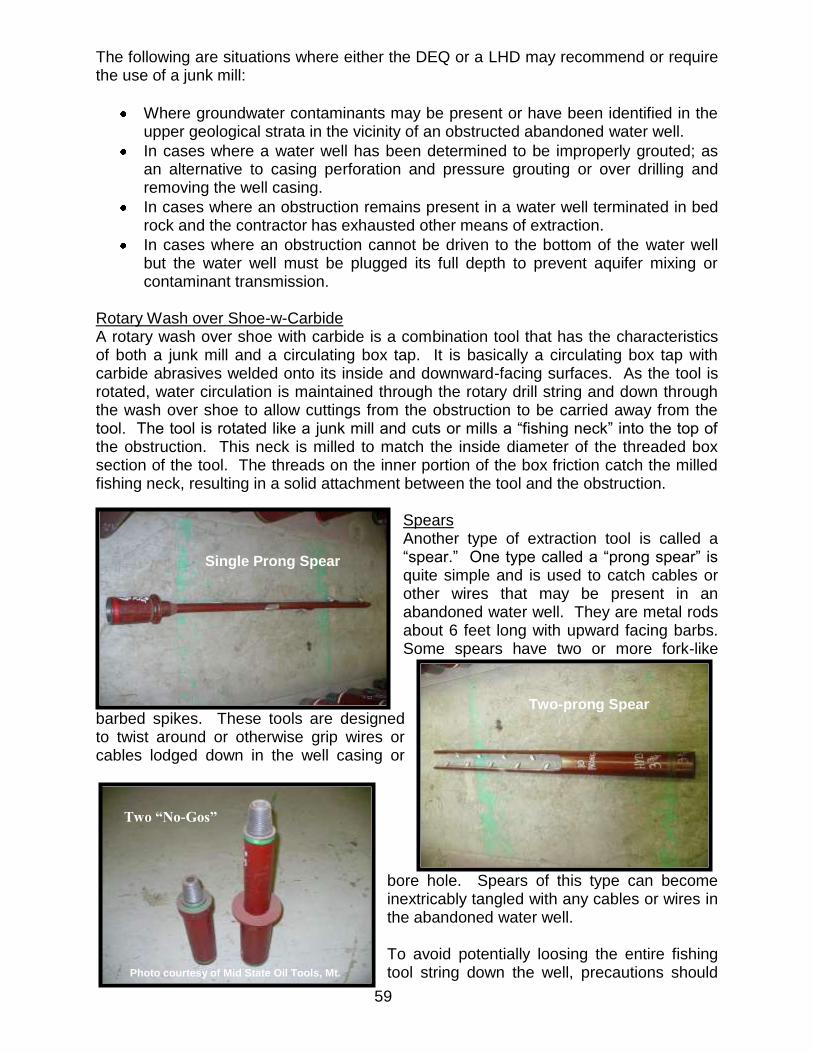
59
The following are situations where either the DEQ or a LHD may recommend or require the use of a junk mill:
Where groundwater contaminants may be present or have been identified in the upper geological strata in the vicinity of an obstructed abandoned water well.
In cases where a water well has been determined to be improperly grouted; as an alternative to casing perforation and pressure grouting or over drilling and removing the well casing.
In cases where an obstruction remains present in a water well terminated in bed rock and the contractor has exhausted other means of extraction.
In cases where an obstruction cannot be driven to the bottom of the water well but the water well must be plugged its full depth to prevent aquifer mixing or contaminant transmission.
Rotary Wash over Shoe-w-Carbide A rotary wash over shoe with carbide is a combination tool that has the characteristics of both a junk mill and a circulating box tap. It is basically a circulating box tap with carbide abrasives welded onto its inside and downward-facing surfaces. As the tool is rotated, water circulation is maintained through the rotary drill string and down through the wash over shoe to allow cuttings from the obstruction to be carried away from the tool. The tool is rotated like a junk mill and cuts or mills a “fishing neck” into the top of the obstruction. This neck is milled to match the inside diameter of the threaded box section of the tool. The threads on the inner portion of the box friction catch the milled fishing neck, resulting in a solid attachment between the tool and the obstruction.
Spears Another type of extraction tool is called a “spear.” One type called a “prong spear” is quite simple and is used to catch cables or other wires that may be present in an abandoned water well. They are metal rods about 6 feet long with upward facing barbs. Some spears have two or more fork-like
barbed spikes. These tools are designed to twist around or otherwise grip wires or cables lodged down in the well casing or
bore hole. Spears of this type can become inextricably tangled with any cables or wires in the abandoned water well. To avoid potentially loosing the entire fishing tool string down the well, precautions should
Single Prong Spear
Two-prong Spear
Photo courtesy of Mid State Oil Tools, Mt. Pleasant, MI
Two “No-Gos”

60
be taken to incorporate a stop, called a “no-go” or a “stop ring” at the point of attachment of the spear to the rotary tool string. A safety thread or other back-off mechanism should be provided above the stop. A second type of tool called a “casing spear” is used to remove sections of liner pipe or larger diameter drop pipe. These tools are used on rotary drill rigs and employ a grapple that is sized based upon the inside diameter of the liner pipe or casing section being fished. Casing Cutters An internal casing cutter is used to sequentially cut off and remove sections of well casing. They employ a set of slips and a set of retractable/deployable knives. Initially, the slips and knives are retracted inside the tool as it is lowered into the target casing or liner pipe. Once inside, the slips are deployed, gripping the casing or liner pipe from the inside, then the knives are hydraulically activated and, with rotation, cut through the casing wall from the inside out.
Inside Casing Cutter
Photo courtesy of Mid State Oil Tools, Mt. Pleasant, MI
Two “No-Gos”
Photo courtesy of Mid-State Oil Tools, Mt. Pleasant, MI
Casing Spear

61
WATER WELL PLUGGING RECORDKEEPING Michigan registered water well drilling contractors and homeowners who plug abandoned water wells must submit an abandoned well plugging record within 60 days from the date the water well was plugged. The properly completed record must be submitted either electronically using the Wellogic statewide groundwater database or on paper using the state approved hard copy form EQP 2044, Abandoned Well Plugging Record. Wellogic and the approved state forms both function the same way. If a replacement water well is drilled, the plugging information for the abandoned water well can be entered on the replacement well drilling record. If an abandoned well is plugged without a replacement well being drilled, a separate plugging record can be submitted. Contractors are strongly encouraged to use Wellogic to submit their abandoned well plugging records. To learn more about submitting well construction and abandonment records electronically using Wellogic, please visit the website www.deq.state.mi.us/wellogic. When completing the abandoned well plugging record, it is important that all required information about the plugging project be reported, specifically:
The location and owner of the abandoned water well.
The depth of the abandoned water well.
The diameter of the well casing and/or borehole.
The type and amount of plugging material used.
Whether obstructions were removed or whether they remain in the water well and the depth at which they are stuck.
Any comments on issues that impacted the outcome of the plugging job.
Name of the person who completed the plugging of the abandoned water well.
If a deviation has been issued by a LHD, indicate so in the comments section.
Reason for not removing an obstruction (include tools used during attempt and length of time expended).
Abandoned Well Plugging Records are state of Michigan legal documents. Fraudulent completion of plugging records is punishable as a criminal offense. Contractors who fail to meet the abandoned well plugging record reporting requirements are subject to administrative action by the DEQ. Data from these records is used for many purposes by state and local agencies; therefore, accuracy is critical. Contractors and homeowners should take the time necessary to properly complete Abandoned Well Plugging Records to help assure that the submitted information accurately represents site conditions.

62
REFERENCES 1. America West Drilling Supply, Atlas Copco Products
www.americawestdrillingsupply.com/products2/Air perforators (accessed September 20, 2010).
2. ASTM D-5299-92, Standard Guide for Decommissioning of Ground Water
Wells, Vadose Zone Monitoring Devices, Boreholes, and Other Devices for Environmental Activities, Second Edition 1999, American Society for Testing Materials, West Conshohocken, Pennsylvania.
3. Brewer, Bryan D., Central Wells & Pumps, Muskegon, MI, May, 2020, personal
communication. 4 Eggington, F. H., The Australian Drillers Guide, First Edition, 1981, National
Library of Australia. 5. Fiedler, A. G., Fishing Jobs and the Use of Fishing Tools, The Johnson National Driller’s Journal, July 1931, Vol. 3-No. 7, St. Paul, Minnesota. 6. Fisher, Brant O., Michigan Department of Environmental Quality, January 2011,
personal communication. 7. Gaber, Michael S., Flowing Well Handbook, 2005, Michigan Department of
Environmental Quality, Lansing, MI. 8. Gaber, M. and Fisher, B., Michigan Water Well Grouting Manual, 1988,
Michigan Department of Public Health, Lansing, MI. 9. Gass, Lehr, and Heiss, Impact of Abandoned Wells on Ground Water, 1977,
USEPA, Ada, Oklahoma. 10. Gotco Tool Company www.gotco-usa.com/accessory-tools/safety_joint and
BumperSub3D and HydraulicFishingJar3D (accessed September 20, 2010). 11. Halliburton Cementing Tables, 1981, Haliburton Services, Duncan, Oklahoma. 12. Halliburton Energy Services www.halliburton.com Directed Explosive Charges
(accessed September 20, 2010). 13. Huntoon, Edwin, Fishing Tools for Water Wells, Circa 1995. 14. Kelley, R. W., Bedrock of Michigan, Small Scale Map 2, 1977, State of
Michigan, Department of Natural Resources, Geology Division.
15. Lalone, Mike, Lalone Well Drilling, September, 2010, personal communication. 16. Logan Oil Tools www.loganoiltools.com/Product-
PDFs/FishingToolsExternalCatch/Lead-Impression-Blocks and Die-Collar (accessed September 20, 2010).

63
17. Machuta, Craig, Mid State Oil Tools, June 2010, personal communication. 18. Minnesota Department of Health, A Well Sealing Primer, March 1997. 19. Smith, S., Well and Borehole Sealing, S.A. Smith Consulting Services, Ada,
Ohio, 1994. 20. Tasco Vacuum Trucks http://vacuumtrucks.com (accessed September 20, 2010). 21. USEPA, Region 5 Superfund NPL Factsheet MI D980794747. Available online:
www.epa.gov/region5superfund/npl/michigan/MID980794747. 22. Wade, Cheryl, “A miracle” 4-year-old falls into well, is rescued by dad,
December 15, 1998, Midland Daily News. 23. Webb, Robert R., A & B Webb Enterprises, Inc., September 2010, personal
communication.
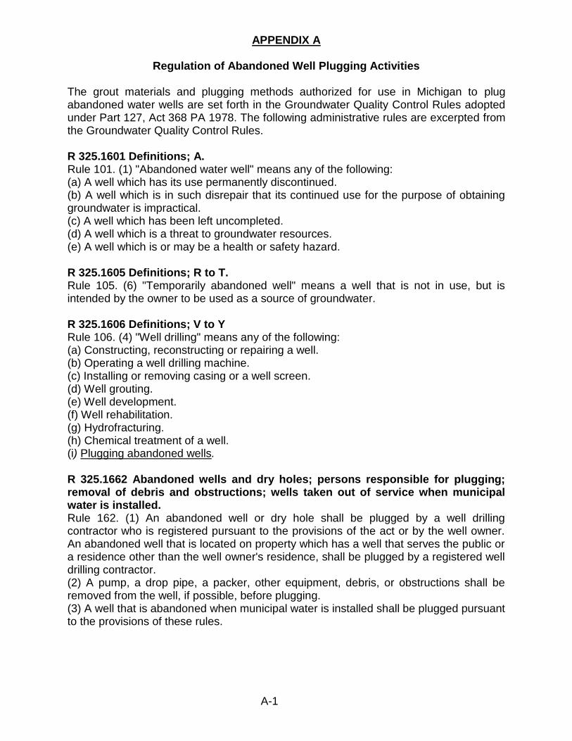
A-1
APPENDIX A
Regulation of Abandoned Well Plugging Activities
The grout materials and plugging methods authorized for use in Michigan to plug abandoned water wells are set forth in the Groundwater Quality Control Rules adopted under Part 127, Act 368 PA 1978. The following administrative rules are excerpted from the Groundwater Quality Control Rules. R 325.1601 Definitions; A. Rule 101. (1) "Abandoned water well" means any of the following: (a) A well which has its use permanently discontinued. (b) A well which is in such disrepair that its continued use for the purpose of obtaining groundwater is impractical. (c) A well which has been left uncompleted. (d) A well which is a threat to groundwater resources. (e) A well which is or may be a health or safety hazard. R 325.1605 Definitions; R to T. Rule 105. (6) "Temporarily abandoned well" means a well that is not in use, but is intended by the owner to be used as a source of groundwater. R 325.1606 Definitions; V to Y Rule 106. (4) "Well drilling" means any of the following: (a) Constructing, reconstructing or repairing a well. (b) Operating a well drilling machine. (c) Installing or removing casing or a well screen. (d) Well grouting. (e) Well development. (f) Well rehabilitation. (g) Hydrofracturing. (h) Chemical treatment of a well. (i) Plugging abandoned wells. R 325.1662 Abandoned wells and dry holes; persons responsible for plugging; removal of debris and obstructions; wells taken out of service when municipal water is installed. Rule 162. (1) An abandoned well or dry hole shall be plugged by a well drilling contractor who is registered pursuant to the provisions of the act or by the well owner. An abandoned well that is located on property which has a well that serves the public or a residence other than the well owner's residence, shall be plugged by a registered well drilling contractor. (2) A pump, a drop pipe, a packer, other equipment, debris, or obstructions shall be removed from the well, if possible, before plugging. (3) A well that is abandoned when municipal water is installed shall be plugged pursuant to the provisions of these rules.
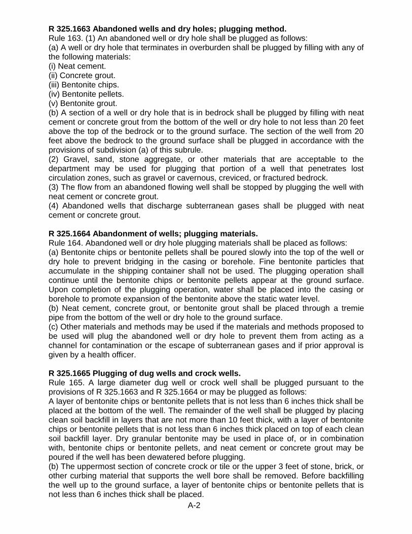
A-2
R 325.1663 Abandoned wells and dry holes; plugging method. Rule 163. (1) An abandoned well or dry hole shall be plugged as follows: (a) A well or dry hole that terminates in overburden shall be plugged by filling with any of the following materials: (i) Neat cement. (ii) Concrete grout. (iii) Bentonite chips. (iv) Bentonite pellets. (v) Bentonite grout. (b) A section of a well or dry hole that is in bedrock shall be plugged by filling with neat cement or concrete grout from the bottom of the well or dry hole to not less than 20 feet above the top of the bedrock or to the ground surface. The section of the well from 20 feet above the bedrock to the ground surface shall be plugged in accordance with the provisions of subdivision (a) of this subrule. (2) Gravel, sand, stone aggregate, or other materials that are acceptable to the department may be used for plugging that portion of a well that penetrates lost circulation zones, such as gravel or cavernous, creviced, or fractured bedrock. (3) The flow from an abandoned flowing well shall be stopped by plugging the well with neat cement or concrete grout. (4) Abandoned wells that discharge subterranean gases shall be plugged with neat cement or concrete grout. R 325.1664 Abandonment of wells; plugging materials. Rule 164. Abandoned well or dry hole plugging materials shall be placed as follows: (a) Bentonite chips or bentonite pellets shall be poured slowly into the top of the well or dry hole to prevent bridging in the casing or borehole. Fine bentonite particles that accumulate in the shipping container shall not be used. The plugging operation shall continue until the bentonite chips or bentonite pellets appear at the ground surface. Upon completion of the plugging operation, water shall be placed into the casing or borehole to promote expansion of the bentonite above the static water level. (b) Neat cement, concrete grout, or bentonite grout shall be placed through a tremie pipe from the bottom of the well or dry hole to the ground surface. (c) Other materials and methods may be used if the materials and methods proposed to be used will plug the abandoned well or dry hole to prevent them from acting as a channel for contamination or the escape of subterranean gases and if prior approval is given by a health officer. R 325.1665 Plugging of dug wells and crock wells. Rule 165. A large diameter dug well or crock well shall be plugged pursuant to the provisions of R 325.1663 and R 325.1664 or may be plugged as follows: A layer of bentonite chips or bentonite pellets that is not less than 6 inches thick shall be placed at the bottom of the well. The remainder of the well shall be plugged by placing clean soil backfill in layers that are not more than 10 feet thick, with a layer of bentonite chips or bentonite pellets that is not less than 6 inches thick placed on top of each clean soil backfill layer. Dry granular bentonite may be used in place of, or in combination with, bentonite chips or bentonite pellets, and neat cement or concrete grout may be poured if the well has been dewatered before plugging. (b) The uppermost section of concrete crock or tile or the upper 3 feet of stone, brick, or other curbing material that supports the well bore shall be removed. Before backfilling the well up to the ground surface, a layer of bentonite chips or bentonite pellets that is not less than 6 inches thick shall be placed.

A-3
R 325.1667 Plugging wells drilled by person other than property owner or registered well drilling contractor. Rule 167. A well that was drilled by a person other than the property owner or by a person other than a well drilling contractor who is registered pursuant to the provisions of the act shall be abandoned and plugged pursuant to the provisions of these rules. R 325.1668 Order to plug abandoned well or dry hole. Rule 168. The department or a health officer may order a well owner or a registered well drilling contractor to plug an abandoned well or a dry hole. R 325.1669 Owner and contractor responsibility for plugging abandoned wells. Rule 169. (1) A well owner shall be responsible for the plugging of an abandoned well, except as provided in a written contract between the owner and a registered well drilling contractor. (2) If a health officer or the department determines that a registered well drilling contractor has improperly located or constructed a well, the well drilling contractor shall be responsible for plugging the well. R 325.1670 Temporarily abandoned wells. Rule 170. (1) A temporarily abandoned well shall be in compliance with the minimum construction and isolation distance requirements of these rules. (2) A temporarily abandoned well shall be disconnected from any water distribution piping and shall have the top of the casing securely capped to prevent the entrance of surface water or foreign materials into the well and to prevent access to the well. R 325.1675 Well records. Rule 175. (3) Within 60 days after plugging an abandoned well or dry hole, the person who performed the plugging operation shall provide the department or local health department with 2 copies of a report that sets forth all of the following information: (a) The well owner's name. (b) The location of the well. (c) The well depth. (d) The well diameter. (e) The plugging procedure. (f) The plugging material. (g) The amount of plugging material used. Standard forms for the report shall be provided by the department. When an abandoned well is plugged where a replacement well will be or has been constructed, the plugging information may be recorded on the well log that is submitted for the replacement well. Information on several abandoned wells or dry holes within a single parcel may be submitted on a single well log form if the geologic materials and plugging methods are similar. (4) A well log shall be signed by a registered well drilling contractor.
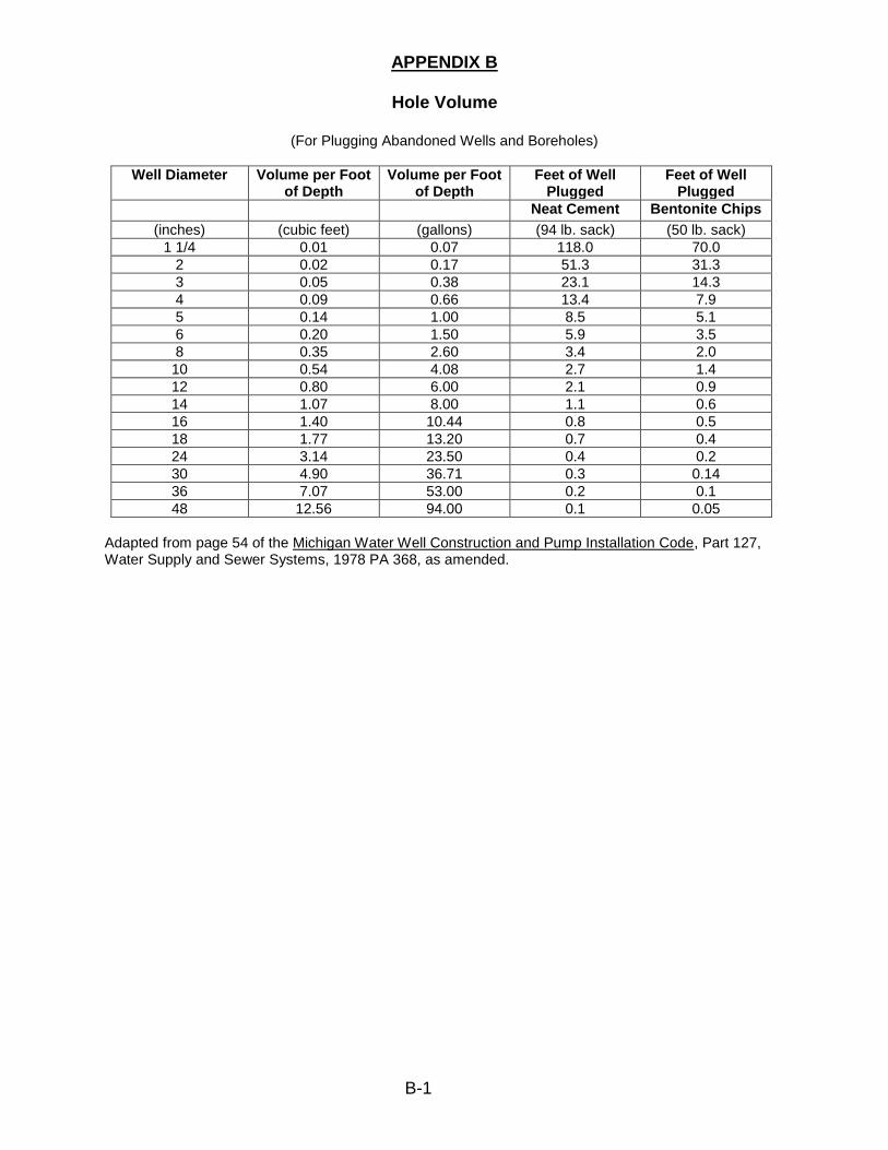
B-1
APPENDIX B
Hole Volume
(For Plugging Abandoned Wells and Boreholes)
Well Diameter Volume per Foot of Depth
Volume per Foot of Depth
Feet of Well Plugged
Feet of Well Plugged
Neat Cement Bentonite Chips
(inches) (cubic feet) (gallons) (94 lb. sack) (50 lb. sack)
1 1/4 0.01 0.07 118.0 70.0
2 0.02 0.17 51.3 31.3
3 0.05 0.38 23.1 14.3
4 0.09 0.66 13.4 7.9
5 0.14 1.00 8.5 5.1
6 0.20 1.50 5.9 3.5
8 0.35 2.60 3.4 2.0
10 0.54 4.08 2.7 1.4
12 0.80 6.00 2.1 0.9
14 1.07 8.00 1.1 0.6
16 1.40 10.44 0.8 0.5
18 1.77 13.20 0.7 0.4
24 3.14 23.50 0.4 0.2
30 4.90 36.71 0.3 0.14
36 7.07 53.00 0.2 0.1
48 12.56 94.00 0.1 0.05
Adapted from page 54 of the Michigan Water Well Construction and Pump Installation Code, Part 127, Water Supply and Sewer Systems, 1978 PA 368, as amended.

C-1
APPENDIX C
Example Calculations for Determining Grout Volumes Necessary to Plug Abandoned Water Wells and Dry Holes
Example: An unplugged 4-inch dry hole terminated in bedrock, sealed with neat cement. 1. Determine the depth and diameter of the borehole to be plugged. a. Example: 4-inch borehole, 150 feet deep, terminated in bedrock. 2. Select the type of plugging material to be used. a. Example: Neat cement is required to plug a well terminated in bedrock. 3. From the Table, for a 4-inch hole, determine the number of feet (# feet) plugged per
bag of plugging material. a. Example: 4-inch hole = 13.4 feet per (94 pound [pd]) bag.
4. Divide the depth of the well to be plugged by the # feet plugged per bag to
determine the number of bags of plugging material needed to complete the sealing of the borehole. a. Example: 150 feet/13.4 feet per bag = 11.2 bags of cement.
5. Because this example is a bedrock borehole, there may be some loss of plugging
material into the formation, so we need to add about 15 percent to the figure in step #4 above. To do this, perform the following calculation: a. 11.2 bags x .15 = 1.68 bags. b. Now add the two values together: 11.2 bags + 1.68 bags = 12.88 bags. c. Then round it up to 13 bags.
6. Answer: Thirteen (13) 94-lb bags of cement are required to plug this 150 foot deep
4 inch diameter borehole. Example: An abandoned 2-inch well terminated in an unconsolidated formation, sealed with bentonite chips 1. Determine the depth and diameter of the well casing and/or borehole to be plugged. a. Example: a 2- inch casing, 75 feet deep, screened in a sand formation. 2. Select the type of plugging material to be used, either neat cement or bentonite
chips. a. Example: Bentonite chips may be used to plug a water well with a screen
terminated in an unconsolidated formation. 3. From the Table for a 2- inch casing, determine the # feet plugged per bag of
plugging material. a. Example: a 2-inch casing = 31.3 feet per (50 lb) bag.

C-2
4. Divide the depth of the well to be plugged by the # feet plugged per bag to determine the number of bags of plugging material needed to complete the sealing of the water well.
a. Example: 75 feet/31.3 feet per bag = 2.4. b. Round to 2.5.
5. Answer: Two and one half (2.5) 50-lb bags of bentonite chips are necessary to plug
this 75 feet deep, 2-inch diameter abandoned water well. Example: An abandoned 5-inch water well terminated in an unconsolidated formation, sealed with bentonite slurry. 1. Determine the depth and diameter of the well casing and/or borehole to be plugged. a. Example: 5-inch casing, 175 feet deep, screened in a sand formation. 2. Select the type of plugging material to be used. In this case we decide to use a
bentonite slurry grout. 3. From the Table, determine the Volume per foot of depth based upon the size of the
well casing being plugged. a. Example: The volume of a 1-foot length of five (5)-inch well casing is 14 cubic
feet, or 1 gallon. 4. To determine the total volume contained inside a 5-inch well casing that is 175 feet
deep, multiply the casing length by the number of gallons or cubic feet in one foot of well casing.
a. Example: 175 feet x .14 cubic feet per foot (from Table) = 24.5 cubic feet, or 175 feet x 1 gallon per foot = 175 gallons.
5. Determine the yield of one bag of bentonite grout (from the manufacturer’s
specification, usually on the bag). a. Example: One (1) 50 lb bag of Brand X bentonite grout yields 4 cubic feet, or
29 gallons of grout. 6. To determine the number of bags of Brand X grout required in cubic feet:
a. divide 24.5 cubic feet (well casing volume) by 4 (# cubic feet yield per 50 lb bag of Brand X grout) = 6.1, round it down to 6 bags.
7. To determine the number of bags of Brand X grout required, in gallons:
a. divide 175 gallons (well casing volume) by 29 (# gallons yield per 50 lb bag of Brand X grout).
8) Answer: 175 gallons/29 gallons per bag = 6 bags. Example: An abandoned 6-inch water well terminated in fractured bedrock with a total depth of 275 feet, which is cased down to 125 feet. The open borehole below the well casing is 5-inch.

C-3
1. Calculate the number of bags of cement needed to plug the cased section of the well.
a. 125 feet of 6 inch casing/5.9 feet of casing plugged per 94 lb bag of cement (from Appendix B Table) = 21.2 bags.
2. Calculate the volume of aggregate (pea stone) needed to fill the open borehole.
a. 150 feet x .14 cubic feet per foot of 5-inch borehole (from Appendix B Table) = 21 cubic feet of aggregate.
b. Some additional aggregate may be needed to fill any large fractures that are present.
c. Round up to one cubic yard, (27 cubic feet). NOTE: If blasting has been performed on the well’s borehole to increase production, then this calculation
would need to take borehole enlargement into account. If a caliper log is available, the calculation is more accurate. It is not unusual for the blast zone to be substantially greater in volume than the initial borehole. This example does not include a calculation for presence of a blast zone.
3. Calculate the amount of cement needed to fill the open borehole interval of the
abandoned water well. a. 150 feet of 5-inch borehole/8.5 feet of borehole plugged per 94 lb bag of
cement (from Appendix B Table) = 17.6 bags of cement. 4. Calculate the standard 15 percent loss into the formation.
a. 17.6 bags x .15 = 2.64 bags. 5. Determine the subtotal for cement in the borehole.
a. 17.6 + 2.64 = 20.24 bags. 6. Because the pea stone aggregate (from #2 above) will be poured into the
abandoned water well from the surface at the same time that the cement is being pumped through the tremie pipe, a cement volume reduction factor may be applied for the open borehole section of the abandoned water well. For this example:
a. a reduction factor of 50 percent will be used. 20.24 bags x .5 = 10.14 bags of cement.
NOTE: The concept is that the pea stone occupies a calculated portion of the open borehole and the
cement will occupy the void space between the pea stone particles. In the field, a factor of 50 percent has been used successfully to calculate the amount of cement required. This estimated percentage may vary from job to job depending upon how tightly the pea stone is packed and depending on the viscosity of the cement.
7. Add the amount of cement needed to plug the cased and uncased well intervals.
a. 20.24 bags + 10.14 bags = 30.38 bags. b. Round it up to 31 bags of cement needed for the job.
8. Answer: Total materials necessary would be:
a. 31 bags of cement. b. 161 gallons of water (5.2 gallons of water per 94 lb sack of Portland cement). c. 1 cubic yard of aggregate (clean pea stone).

D-1
APPENDIX D
Additions to the Abandoned Water Well Plugging Manual added after February 2012
This appendix is intended to allow DEQ to periodically add information to the Michigan Abandoned Water Well Plugging Manual. As new or additional tools, equipment, methods, or materials are developed, the information will be made available to water well drilling contractors and LHDs in a format that allows it to be added here.

D-2
MICHIGAN DEPARTMENT OF ENVIRONMENTAL QUALITY – RESOURCE MANAGEMENT DIVISION Drinking Water and Environmental Health Section
Environmental Health Programs Unit March 2012
ADDENDUM TO APPENDIX D
WATER WELL CASING REMOVAL
In some locations where groundwater contamination is present and unplugged abandoned water wells are identified, in order to positively seal the abandoned water wells, it may be necessary to remove the abandoned water well casings. Due to less stringent grouting requirements in effect at the time, older rotary-drilled wells installed in Michigan prior to the mid-1970’s may have an unsealed or partially sealed annulus between the borehole and the well casing. Also, where DEQ or LHDs have identified grout failure or improper grouting associated with a newer well, they may require the well casing and the improper grout to be removed before final plugging of the abandoned water well can commence. Wash over bit One method used to accomplish grout and casing removal is to use a wash over bit to drill out and remove the grout material from around the well casing. Heavy drilling mud is used to convey the cuttings (the drilled-out grout) to the surface. After the grout is removed, the well casing can be pulled. It is important to avoid formation collapse during the wash over process, while pulling the wash over tool string, and while removing the well casing from the borehole. Depending upon the grout material to be removed, different bit configurations may be used. Wash over bits are used in conjunction with steel drill pipe (well casing sections) that are either welded or threaded and coupled together. Heavy drilling mud is conveyed down hole inside the steel drill pipe and out the end of the wash over bit. The following example shows 6-inch steel drill pipe and a driller-fabricated roller cone wash over bit. It was used to remove cement grout from around a 4-inch steel well casing from a 260 feet deep well. Lost circulation zones and unstable geological formations, if present, can cause problems with keeping the bore hole open during the abandonment process. The ability to maintain effective drilling mud circulation and good drilling mud viscosity is critical to avoid formation collapse as the wash over and casing removal activities proceed.
DEQ Photo
11 inch (O.D.) x 4.5 inch (I.D.) Roller Cone Wash Over Bit
6 Inch Drill Pipe